
Flame Stabilization Enhancement and NOx Production using Ultra
13
Flame Stabilization Enhancement and NOx Production using Ultra Short Repetitively Pulsed Plasma Discharges W. Kim * , H. Do † , M.G. Mungal ‡ and M.A. Cappelli § Stanford University, Stanford, CA, 94305-3032 This paper examines the use of plasma discharges in flame stabilization. Three different types of plasma discharges are applied to a lifted jet diffusion flame in a coflow configuration, and evaluated for their abilities to enhance flame stabilization. A single electrode corona discharge (SECD) between a platinum electrode and the flame base is found to maintain the flame at a 20% higher coflow speed than that without the discharge. An asymmetric dielectric barrier discharge (DBD) results in flame stabilization at up to 50% higher coflow speed. The nonequilibrium properties of the DBD are characterized by a spectral line analysis and simulation of the nitrogen 2 nd positive system. Finally, an ultra short repetitively-pulsed discharge (USRD, pulse width of ~10ns) is used in an opposed platinum electrode configuration and found to increase in the stability limit by nearly ten- fold. The degree of nonequilibrium of this pulsed discharge is found to be higher than that of the DBD. The stabilization process is sensitive to the positioning of the discharge in the flame flow field, and the optimal position of the discharge is mapped into mixture fraction space by comparing the emission spectra from the plasma-stabilized flame to that in a fully premixed reference flame. The result shows that the local mixture fraction at the optimal position is much leaner than that of a conventional lifted jet flame. In a second part of this study, the USRD is used to stabilize lean premixed methane flames. Nitric Oxide (NO) production is measured using probe sampling and chemiluminescence analysis. While the discharge is a potential source of NO, it is found that the flame partially consumes NO in a reburn mode. The NO production is modeled by use of PLASMAREACTOR followed by the standard PREMIX code. The modeling results show some promise in its ability to predict NO concentration. The flame structure of plasma assisted premixed combustion is also discussed. Under certain conditions, we observe a cold inner flame that has an abundance of OH radicals which have an unusually high vibrational temperature with low rotational temperature when compared to the OH found in a conventional lean premixed flame. While the role of the OH in this inner flame is not fully understood, we believe it may be important in igniting the surrounding combustible mixture. I. Introduction HE issue of flame stability is receiving renewed attention in the burning of gaseous hydrocarbons because of increased demand for high power/low emission combustion and the trend towards the utilization of low grade fuels. Techniques which seek to improve flame stability should not lead to increased emission. Hence, in this study, we investigate both flame stability and NOx production in flames subjected to plasma enhancement. T Several major methods have been used to achieve stabilization in combustion flames. These include the use of pilot flames, bluff bodies and swirl amongst others. Pilot flames have been implemented in laboratory scale, non- premixed flames 1-2 and premixed flames. 3-5 A pure oxygen coflow surrounding a jet flame was demonstrated in laboratory-scale diffusion flames. 6 Bluff bodies or swirl stabilization mechanisms have been used in premixed and partially premixed flames to generate a recirculation zone which preheats the reactants, resulting in increased flame stability. 7-10 However, increasing entrainment of high temperature burned gas into the fresh reacting jet can also lead to a significant increase in the formation of NOx. As in the case of a pilot flame, these two methods have an intrinsic * Graduate Research Assistant, Mechanical Engineering, AIAA Student Member. † Graduate Research Assistant, Mechanical Engineering, AIAA Student Member. ‡ Professor, Mechanical Engineering, AIAA Associate Fellow. § Professor, Mechanical Engineering, AIAA Member. American Institute of Aeronautics and Astronautics 1 44th AIAA Aerospace Sciences Meeting and Exhibit 9 - 12 January 2006, Reno, Nevada AIAA 2006-560 Copyright © 2006 by the American Institute of Aeronautics and Astronautics, Inc. All rights reserved.
Transcript of Flame Stabilization Enhancement and NOx Production using Ultra

Flame Stabilization Enhancement and NOx Production using Ultra Short Repetitively Pulsed Plasma Discharges
W. Kim*, H. Do†, M.G. Mungal‡ and M.A. Cappelli§
Stanford University, Stanford, CA, 94305-3032
This paper examines the use of plasma discharges in flame stabilization. Three different types of plasma discharges are applied to a lifted jet diffusion flame in a coflow configuration, and evaluated for their abilities to enhance flame stabilization. A single electrode corona discharge (SECD) between a platinum electrode and the flame base is found to maintain the flame at a 20% higher coflow speed than that without the discharge. An asymmetric dielectric barrier discharge (DBD) results in flame stabilization at up to 50% higher coflow speed. The nonequilibrium properties of the DBD are characterized by a spectral line analysis and simulation of the nitrogen 2nd positive system. Finally, an ultra short repetitively-pulsed discharge (USRD, pulse width of ~10ns) is used in an opposed platinum electrode configuration and found to increase in the stability limit by nearly ten-fold. The degree of nonequilibrium of this pulsed discharge is found to be higher than that of the DBD. The stabilization process is sensitive to the positioning of the discharge in the flame flow field, and the optimal position of the discharge is mapped into mixture fraction space by comparing the emission spectra from the plasma-stabilized flame to that in a fully premixed reference flame. The result shows that the local mixture fraction at the optimal position is much leaner than that of a conventional lifted jet flame. In a second part of this study, the USRD is used to stabilize lean premixed methane flames. Nitric Oxide (NO) production is measured using probe sampling and chemiluminescence analysis. While the discharge is a potential source of NO, it is found that the flame partially consumes NO in a reburn mode. The NO production is modeled by use of PLASMAREACTOR followed by the standard PREMIX code. The modeling results show some promise in its ability to predict NO concentration. The flame structure of plasma assisted premixed combustion is also discussed. Under certain conditions, we observe a cold inner flame that has an abundance of OH radicals which have an unusually high vibrational temperature with low rotational temperature when compared to the OH found in a conventional lean premixed flame. While the role of the OH in this inner flame is not fully understood, we believe it may be important in igniting the surrounding combustible mixture.
I. Introduction HE issue of flame stability is receiving renewed attention in the burning of gaseous hydrocarbons because of increased demand for high power/low emission combustion and the trend towards the utilization of low grade
fuels. Techniques which seek to improve flame stability should not lead to increased emission. Hence, in this study, we investigate both flame stability and NOx production in flames subjected to plasma enhancement.
T Several major methods have been used to achieve stabilization in combustion flames. These include the use of
pilot flames, bluff bodies and swirl amongst others. Pilot flames have been implemented in laboratory scale, non-premixed flames1-2 and premixed flames.3-5 A pure oxygen coflow surrounding a jet flame was demonstrated in laboratory-scale diffusion flames.6 Bluff bodies or swirl stabilization mechanisms have been used in premixed and partially premixed flames to generate a recirculation zone which preheats the reactants, resulting in increased flame stability.7-10 However, increasing entrainment of high temperature burned gas into the fresh reacting jet can also lead to a significant increase in the formation of NOx. As in the case of a pilot flame, these two methods have an intrinsic * Graduate Research Assistant, Mechanical Engineering, AIAA Student Member. † Graduate Research Assistant, Mechanical Engineering, AIAA Student Member. ‡ Professor, Mechanical Engineering, AIAA Associate Fellow. § Professor, Mechanical Engineering, AIAA Member.
American Institute of Aeronautics and Astronautics
1
44th AIAA Aerospace Sciences Meeting and Exhibit9 - 12 January 2006, Reno, Nevada
AIAA 2006-560
Copyright © 2006 by the American Institute of Aeronautics and Astronautics, Inc. All rights reserved.

limit in that the main energy transfer occurs predominantly in the form of thermal energy, which implies that a portion of it is lost while local thermal equilibrium is established.11
Here, we describe the use of a plasma discharge to enhance the stability of a lifted methane jet flame. This method is different from those mentioned above in that it creates cold radicals in a combustible mixture. Although the translational temperature of the radicals is close to room temperature, the more important temperatures in reaction kinetics – i.e. electronic and vibrational temperatures – can be much higher, giving rise to faster rates of branching reactions. This nonequilibrium plasma assisted energy mode targeting can be achieved by decreasing the discharge time scale (e.g., short pulse discharges). When the discharge time is less than the energy transfer time between electronic and translational modes, one can promote nonequilibrium in that most of the energy added by the discharge is used for accelerating chemical reactions rather than increasing the local gas temperature.
Various methods of achieving ultra short-pulsed (~10ns) discharges have been reported for applications to flame stabilization. Among these are the dielectric barrier discharges (DBD), which are known to achieve highly nonequilibrium conditions.12-18 Nonequilibrium corona discharges have also been implemented with a fair degree of success.19 These types of discharges have the advantages of being relatively simple to integrate into a combustion experiment, are of relatively low cost, and introduce minimal electromagnetic interference. However, in practice, DBD and corona discharges in air or air-fuel mixtures at high pressure tend to be filamentary, giving rise to bursts of micro discharges, of peak current and frequency that are not directly controllable. In contrast, one of the plasma used in this study is generated by an ultra short-pulse repetitive discharge (USRD). The single repetitive pulses of frequency as high as 100 kHz can lead to a peak discharge current that is much higher than those generated by the filamentary bursts in these other discharges.20-22 A comparison of the ability of these discharges, i.e., the single electrode corona discharge (SECD), DBD, and USRD to extend flame stability will be one of the main focuses of our current study.
The current understanding of the stabilization mechanism of a natural lifted jet flame is that of a leading edge flame of triplet character for both laminar and turbulent jets, which implies that the flame base is anchored instantaneously on a triple point of three branches where a competition occurs between the flame propagation speed and the local flow velocity.23,24 This perspective matches well to our previous observations in which the lifted flame base is located in a flow field whose local flow velocity is two to three times that of the laminar flame speed (SL).25 Therefore, the natural lifted jet flame is considerably more difficult to stabilize at velocities exceeding 2~3SL of coflow speed regardless of velocity of the jet.26 Thus, in the first part of current study, we use coflow speed as one of the main criteria to evaluate the degree of improvement of discharge-assisted diffusion flame stabilization along with the commonly used jet velocity. Furthermore, the electrode placement which provides maximum stability to a lifted jet flame will be investigated in comparison to a conventional flame system.
In the later part of this paper, we describe preliminary results of a study of nitric oxide (NO) production and flame structure of a USRD assisted lean premixed methane flame. While stability improvements in plasma assisted premixed flames have been reported previously, few of these studies investigate the associated impact of the plasma on NO production. Also, the alteration of premixed flame structure due to an applied plasma discharge has not been fully examined.
NO production in conventional combustion systems can be categorized into four mechanisms: thermal, prompt, nitrous oxide and NO production due to nitrogen in the fuel.27,28 Among these mechanisms, the thermal NO mechanism is the most sensitive to temperature change, becoming less dominant at very lean mixture conditions. However, when a plasma discharge is added to the system, the thermal mechanism becomes more complex since the combined system departs from thermal equilibrium and vibrational and electronic temperatures can be considerably different than the gas temperature. For example, the discharge generates electronically excited species such as N2, OH, CN, CH and H while the translational temperature of the system is only ~400K. These excited molecules or radicals can alter the critical NO production mechanisms. For example, excited N2 will increase the forward reaction coefficient of the thermal NO rate controlling reaction (1), or can lead to faster NNH production resulting in higher NO concentrations (Reactions (2) and (3)).
O + N2 ↔ NO + N (1) N2 + H ↔ NNH (2) NNH + O ↔ NO + NH (3)
Also, super-equilibrium concentrations of OH can accelerate another important thermal NO production mechanism (Reaction (4)),
American Institute of Aeronautics and Astronautics
2

c) b)a)
Figure 1. Schematic of the experimental setup. a) Setup overview b) Meso-scale array burner (c) Conventional premixed nozzle used.
N + OH ↔ NO + H (4)
Furthermore, CN produced in the discharge may lead to similar NO formation as that of fuel-bound-nitrogen NO formation in a conventional flame system. The abundance of CH can produce additional NO through a process similar to the generation of prompt NO. Finally, the NO production due to collisions with hot electrons should also be considered (Reactions (5), (6) and (7)).29
e + N2 ↔ N + N + e (5) e + O2 ↔ O + O + e (6) N + O ↔ NO (7)
Therefore, the above discussion implies that the altered NO production of plasma stabilized combustion systems should also be factored in when considering the benefits of plasma stabilization, even though plasmas can extend a combustion system into the very lean regime.
II. Experimental Setup A schematic diagram of the experimental setup is provided in Fig. 1a. A lifted methane jet diffusion flame and
for some studies, premixed flames are formed in a vertical wind tunnel that is 30×30cm in its cross section. For the diffusion flame, a nozzle with inner diameter of 4.6mm is oriented parallel to the flow direction to produce a jet in coflow. Figures 1b and 1c shows premixed burners used. The burner shown in Fig. 1c is a conventional nozzle stabilized premixed burner whose inner diameter is 45mm while Fig. 1b is a swirl stabilized meso-scale 6×6 array burner. The diameter of individual elements for the array burner is 4.5mm and the overall burner diameter is 44mm. A more detailed description of the burner is given in ref. 30. The quantitative measurements, including NO concentration measurements, are conducted using the array burner while spectrum analysis of the plasma/flame system is performed using the conventional burner.
Coflow speed is measured by a PIV system while jet velocity is determined by measuring pressure and volume flow rate upstream using flowmeters. The PIV system consists of a 15 Hz, double exposure interlaced CCD camera (Kodak ES 1.0), 15 Hz double pulse 2nd harmonic Nd:YAG laser (Spectraphysics PIV-400) and an alumina particle seeding system. Also, an ICCD camera (Princeton instrument PI-MAX) which has 50 kHz maximum gating frequency and 1.5nm minimum gating width is used to visualize the plasma discharge in a time resolved manner. The voltage and current at the electrode is recorded with a 1000:1 high voltage probe (Tektronics P6015A) and Rogowski coil (Pearson Electronics, model 2877) respectively. In addition, we also record spectrally-resolved
American Institute of Aeronautics and Astronautics
3
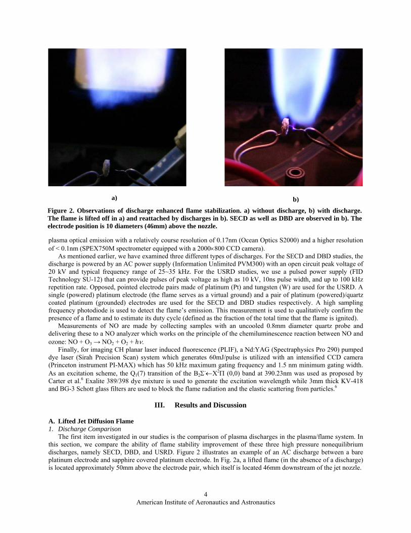
Figure 2. Observations of discharge enhanced flame stabilization. a) without discharge, b) with discharge. The flame is lifted off in a) and reattached by discharges in b). SECD as well as DBD are observed in b). The electrode position is 10 diameters (46mm) above the nozzle.
b) a)
plasma optical emission with a relatively course resolution of 0.17nm (Ocean Optics S2000) and a higher resolution of < 0.1nm (SPEX750M spectrometer equipped with a 2000×800 CCD camera).
As mentioned earlier, we have examined three different types of discharges. For the SECD and DBD studies, the discharge is powered by an AC power supply (Information Unlimited PVM300) with an open circuit peak voltage of 20 kV and typical frequency range of 25~35 kHz. For the USRD studies, we use a pulsed power supply (FID Technology SU-12) that can provide pulses of peak voltage as high as 10 kV, 10ns pulse width, and up to 100 kHz repetition rate. Opposed, pointed electrode pairs made of platinum (Pt) and tungsten (W) are used for the USRD. A single (powered) platinum electrode (the flame serves as a virtual ground) and a pair of platinum (powered)/quartz coated platinum (grounded) electrodes are used for the SECD and DBD studies respectively. A high sampling frequency photodiode is used to detect the flame’s emission. This measurement is used to qualitatively confirm the presence of a flame and to estimate its duty cycle (defined as the fraction of the total time that the flame is ignited).
Measurements of NO are made by collecting samples with an uncooled 0.8mm diameter quartz probe and delivering these to a NO analyzer which works on the principle of the chemiluminescence reaction between NO and ozone: NO + O3 → NO2 + O2 + hν.
Finally, for imaging CH planar laser induced fluorescence (PLIF), a Nd:YAG (Spectraphysics Pro 290) pumped dye laser (Sirah Precision Scan) system which generates 60mJ/pulse is utilized with an intensified CCD camera (Princeton instrument PI-MAX) which has 50 kHz maximum gating frequency and 1.5 nm minimum gating width. As an excitation scheme, the Q1(7) transition of the B2Σ-←X2Π (0,0) band at 390.23nm was used as proposed by Carter et al.6 Exalite 389/398 dye mixture is used to generate the excitation wavelength while 3mm thick KV-418 and BG-3 Schott glass filters are used to block the flame radiation and the elastic scattering from particles.6
III. Results and Discussion
A. Lifted Jet Diffusion Flame 1. Discharge Comparison
The first item investigated in our studies is the comparison of plasma discharges in the plasma/flame system. In this section, we compare the ability of flame stability improvement of these three high pressure nonequilibrium discharges, namely SECD, DBD, and USRD. Figure 2 illustrates an example of an AC discharge between a bare platinum electrode and sapphire covered platinum electrode. In Fig. 2a, a lifted flame (in the absence of a discharge) is located approximately 50mm above the electrode pair, which itself is located 46mm downstream of the jet nozzle.
American Institute of Aeronautics and Astronautics
4
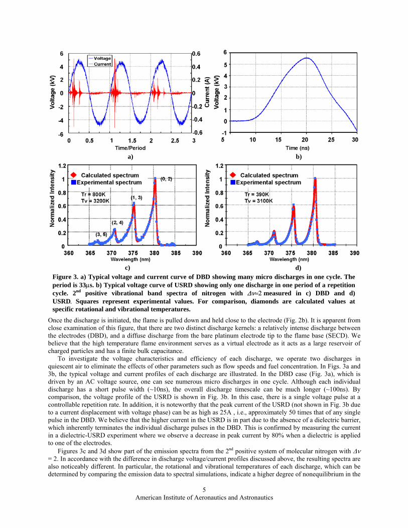
Figure 3. a) Typical voltage and current curve of DBD showing many micro discharges in one cycle. The period is 33µs. b) Typical voltage curve of USRD showing only one discharge in one period of a repetition cycle. 2nd positive vibrational band spectra of nitrogen with ∆ν=2 measured in c) DBD and d) USRD. Squares represent experimental values. For comparison, diamonds are calculated values at specific rotational and vibrational temperatures.
a) b)
c) d)
Once the discharge is initiated, the flame is pulled down and held close to the electrode (Fig. 2b). It is apparent from close examination of this figure, that there are two distinct discharge kernels: a relatively intense discharge between the electrodes (DBD), and a diffuse discharge from the bare platinum electrode tip to the flame base (SECD). We believe that the high temperature flame environment serves as a virtual electrode as it acts as a large reservoir of charged particles and has a finite bulk capacitance.
To investigate the voltage characteristics and efficiency of each discharge, we operate two discharges in quiescent air to eliminate the effects of other parameters such as flow speeds and fuel concentration. In Figs. 3a and 3b, the typical voltage and current profiles of each discharge are illustrated. In the DBD case (Fig. 3a), which is driven by an AC voltage source, one can see numerous micro discharges in one cycle. Although each individual discharge has a short pulse width (~10ns), the overall discharge timescale can be much longer (~100ns). By comparison, the voltage profile of the USRD is shown in Fig. 3b. In this case, there is a single voltage pulse at a controllable repetition rate. In addition, it is noteworthy that the peak current of the USRD (not shown in Fig. 3b due to a current displacement with voltage phase) can be as high as 25A , i.e., approximately 50 times that of any single pulse in the DBD. We believe that the higher current in the USRD is in part due to the absence of a dielectric barrier, which inherently terminates the individual discharge pulses in the DBD. This is confirmed by measuring the current in a dielectric-USRD experiment where we observe a decrease in peak current by 80% when a dielectric is applied to one of the electrodes.
Figures 3c and 3d show part of the emission spectra from the 2nd positive system of molecular nitrogen with ∆ν = 2. In accordance with the difference in discharge voltage/current profiles discussed above, the resulting spectra are also noticeably different. In particular, the rotational and vibrational temperatures of each discharge, which can be determined by comparing the emission data to spectral simulations, indicate a higher degree of nonequilibrium in the
American Institute of Aeronautics and Astronautics
5

T able 1. Observed properties of three discharges investigated. Sign ‘-’ represents uninvestigated properties. tigated. Sign ‘-’ represents uninvestigated properties.
SECD SECD DBD DBD USRD USRD
Power source AC AC DC
Typical peak voltage 1kV 5kV 5kV
Typical peak current - 0.5A 25A
Typical frequency - 25~40kHz 15~50kHz
Typical pulse width - 10 ns (multiple) 10 ns (single)
EM noise Negligible Moderate Very high
Electrode Metal-flame Metal-dielectric Metal-metal
Pulse controllability Impossible Difficult Easy
Degree of noneq. - Good Better
Power Consumption ~0.1W ~1W ~10W
Cost Low Low High
USRD. The higher nonequilibrium temperatures in the USRD has important consequences, particularly in terms of discharge efficiency since the rotational temperature rapidly reaches equilibrium with the translational temperature USRD. The higher nonequilibrium temperatures in the USRD has important consequences, particularly in terms of discharge efficiency since the rotational temperature rapidly reaches equilibrium with the translational temperature (which determines the gas heating) while the vibrational temperature is an important parameter that reflects the chemical reactivity of molecules. Thus we find that the USRD affords not only a higher current density but also potentially higher performance in affecting the flame behavior, largely because of the higher vibrational temperatures and lower rotational temperatures generated in the discharge. In Table 1, a comparison of the three discharges is summarized. We believe it is important to note that the typical power consumptions of all three discharges are less than or equal to 0.1% of the chemical power of our system.
(which determines the gas heating) while the vibrational temperature is an important parameter that reflects the chemical reactivity of molecules. Thus we find that the USRD affords not only a higher current density but also potentially higher performance in affecting the flame behavior, largely because of the higher vibrational temperatures and lower rotational temperatures generated in the discharge. In Table 1, a comparison of the three discharges is summarized. We believe it is important to note that the typical power consumptions of all three discharges are less than or equal to 0.1% of the chemical power of our system. a) b) Figure 4. a) The improvement of liftoff jet velocity as a function of normalized coflow speed. Stability
limits are extended to 2.5SL, 3SL and 20SL with SECD, DBD and USRD, respectively. The input P-P voltage is 9.35 kV and the frequency is 30 kHz in SECD and DBD, while USRD uses 6 kV and 15 kHz of frequency. The electrode position is fixed at 10 diameters downstream. b) A sample picture of a marginally stable lifted methane jet flame via USRD.
American Institute of Aeronautics and Astronautics
6

a) b) Figure 5. a) Emission spectra of various jet mixtures. b) Emission intensity as a function of discharge position along the radial direction obtained at x/d=8.5.
The dramatic enhancement in flame stabilization due to the applied discharges is summarized by the data in Fig.
4a. Here the coflow speed is used as a variable against which the critical jet velocity for liftoff is compared. SECD increases the stability by 20-30% compared to the natural flame while DBD shows 50% stability enhancement. For the AC discharges, it appears that the DBD mode shows much promise in enhancing flame stability compared to SECD, most likely due to its ability to support a higher discharge current density. A further advantage of the DBD mode is that it can be sustained in the absence of the flame, in contrast to the SECD mode, where the flame serves as a virtual ground electrode. It is noteworthy that the maximum coflow speed in which the flame is stably anchored to the electrode can be extended to around 3SL even with just a modest discharge power of 0.5W – only approximately 0.005% of the rate of energy released by the flame itself. However, the most significant improvement is observed in the USRD mode. This approach enhances the flame stability limit by nearly ten-fold. We believe this is due to its higher current density than those of AC discharges mentioned above. The power consumption of USRD in this graph is around 15W, i.e., considerably greater than the other two discharges. This higher dissipated power is clearly advantageous and makes a direct comparison difficult at this time. The black squares in Fig. 4a represent USRD results from a 20% nitrogen/ 80% methane mixture to simulate a low grade fuel. It is apparent that the USRD still results in a significant enhancement of flame stability even in such low purity environment. The photograph shown in Fig. 4b is an example of a flame marginally stabilized by the USRD. The flamebase is unusually stretched due to the high strain rate caused by a high coflow speed (~20SL). 2. Determination of optimal discharge positioning
It is well known that the location where a lifted jet flame is naturally stabilized is closely related to the distribution of a specific fuel/air mixture fraction. For example, Joedicke et al. showed that the average position of a naturally stabilized lifted flame base is located on the region of approximately stoichiometric mixture fraction (Z/Zst=1.14).24 To investigate the optimal discharge position in physical space and map it to mixture fraction space, we used two approaches: (i) physical scanning of the electrode in the jet in coflow configuration, and (ii) comparing the results with those from a fully premixed environment of known equivalence ratio. Since the direct measurement of mixture fraction in a turbulent diffusion flame is not straightforward, we exploit an advantage of the discharge emission spectra change when local mixture fraction varies. Figure 5a shows the typical discharge emission spectra in a pure air jet and a methane/nitrogen jet in a coflow of air. For the methane/nitrogen jet, while most of the emission spectra are caused by excited molecular nitrogen as in the pure air jet (blue), one can observe strong CN bands near 388nm along with CH and C2 bands (red).
In Figure 5b, the emission intensity of CN near 388nm plotted along with that of N2 near 337nm as a function of jet radial position for various voltages. This graph suggests two important points. First, the emission intensities of CN and N2 are monotonic functions of radial position which suggests their ratio can be utilized as an indicator of mixture fraction. While CN could be used by itself, N2 provides a robust reference intensity thus minimizing errors due to possible solid angle difference in each emission spectrum measurement, while the ratio of CN to N2 increases the overall sensitivity. Second, the intensities are also functions of discharge peak voltage which requires that voltage and frequency must be preset to use the CN/N2 ratio as an absolute mixture fraction indicator.
American Institute of Aeronautics and Astronautics
7

)
Figure 6. a) Flame duty cycle co-plotted with CN/N2 ratio. The optimal position of the discharge corresponds to CN/N2 = 0.25. b) Emission spectra in fully premixed environment. CN/N2 = 0.25 corresponds to 0.65 equivalence ratio under premixed conditions.
Figure 6a illustrates a typical result of the measured flame duty cycle used to find the optimal physical placement
of the discharge to maximize flame stability. Also shown is the CN/N2 emission intensity ratio as a function of discharge position at a specific height (x=8.5d), voltage (6 kV) and repetition frequency (15 kHz). As shown, the optimal electrode position which corresponds to maximum duty cycle is 1.6d outward from the center of the jet at these conditions. Since the mixture fraction of a diffusion flame is a function of downstream position as well as radial position, the corresponding optimal position of a discharge will vary with the downstream electrode location. However, it is noteworthy that the CN/N2 intensity ratio corresponding to any optimal discharge position is unaffected and remains at 0.25.
As a final step to determine the absolute mixture fraction value which corresponds to a value of 0.25 in the CN/N2 intensity ratio, Fig. 6b shows the result from the fully premixed flame where the CN/N2 ratio is measured as a function of equivalence ratio for various voltages. For our voltage and frequency condition as shown in the black solid line, the optimal positioning of the discharge is towards much leaner conditions (Z/Zst~0.65) than that of a conventional lifted jet flame. We believe this difference is caused by a convolution of the effects of the difference of the electron energy distribution function and the species’ cross sections near the discharge, causing a resulting variation of the net discharge power and radical concentrations. These conjectures would, however, require further investigations.
B. Lean Premixed Flame 1. Measurement of nitric oxide production
We begin our investigation by carrying out single point measurements of NO production by a plasma discharge in pure ambient air. As expected, the presence of the discharge leads to a significant level of NO, typically 80-
100ppm measured 10mm above the discharge. This amount of NO production seems very large when compared to that generated by conventional combustion in this burner (~10ppm).31 However, the difference must be put into prospective by factoring in that the discharge is a localized source while the flame is distributed over the nozzle area. For example, if the production of NO by the discharge is uniformly distributed over the entire burner area, then it will have an effective concentration of 5ppm. This will be discussed in more detail later.
Figure 7 illustrates the spatial distribution of NO concentration along the electrode for three different equivalence ratios: φ= 0, 0.33 and 0.49, at a position 10mm above the electrode. The first noticeable feature is that the distribution of NO is highly biased towards the cathode side of the discharge (centered at a position of 0 mm in the figure). We attribute this to an asymmetric production of radicals by
Figure 7. NO concentration distribution alongelectrode direction at 10mm above the electrode. NO emission is strongly biased to the cathodeside. Also, the existence of the inner flameconsumes NO.
a
American Institute of Aeronautics and Astronautics
8
b)

the discharge, biased towards the cathode due to collisions between accelerated electrons and neutral molecules in the cathode fall. For a discharge in pure air, the NO concentration level is below detectable limits beyond a position of -5mm from center (where the minus sign implies the anode side). It rapidly increases and levels off by +15mm to a value of 120ppm. When methane is added to the air, the tendency is largely the same but the height of the plateau increases slightly. We believe this slight increase in the NO level is due to a slight increase in the discharge power. Increased power dissipation can lead to an increase in reactive species responsible for NO formation, such as excited N2, O, OH, etc. However, when the equivalence ratio is further increased (e.g., to φ= 0.49), a visible flame appears (ignition) coincident with a drop in the NO concentration by 20% near the plateau region. Since the region of the plateau is well matched with the location of the visible flame, less NO in the plateau can be partial evidence for the consumption of NO by the flame which was produced from the discharge. In essence, it appears that in a plasma/flame system, the plasma discharge may be a major source of NO and
the flame consumes it (partially), similar to a reburn process.
Figure 8. Normalized NO concentration as afunction of equivalence ratio. Sampling is doneat two different locations. NO consumption ofinner flame is clearly seen. In addition, beforethe flame ignition, the intensity of N2 C-B(0,0) emission is well correlated with NO production. Red dotted line represents the start of visibleflame.
In Fig. 8, the normalized NO concentration is shown as a function of equivalence ratio at two different spatial points: the electrode center and the visible flame center. This graph shows that the NO concentration slowly increases with increasing equivalence ratio up to a value of φ = 0.3. This gradual increase is believed to be due to improved power coupling to the gas, mentioned earlier. However, a further increase in equivalence ratio beyond 0.3 reverses the trend. We believe that this drop in NO concentration is also due to the change in the power dissipation, as the increase in methane mole fraction gives rise to reduced plasma conductivity. The overall behavior suggests that there is an optimum equivalence ratio for Ohmic dissipation, established by a balance between the introduction of more easily ionizeable species at low equivalence ratio, and a reduction in electron mobility at too high of an equivalence ratio. This conjecture is supported by the trend seen in the emission intensity of the 2nd positive system of N2 (0,0), shown as red squares in the figure. The intensity of the emission should be a reflection of the power coupling to the plasma, and agrees well with the trend seen in NO concentration before flame ignition, represented by the vertical dashed line in Fig. 8. At equivalence ratios just beyond flame ignition, there is a notable decrease of NO level consistent with the earlier result represented by Fig. 7 especially at the flame center (blue diamonds). This phenomenon is also apparent in the data taken from the electrode center region (green triangles). It is noteworthy that there is no corresponding drop in the emission intensity, suggesting that the change in NO signal is not due to a change in discharge power coupling. Just beyond an equivalence ratio of φ = 0.52, the trend abruptly reverses again, and there is an increase in NO
concentration. We attribute this increase to the introduction of another NO formation mechanism related perhaps to the thermal NO production often seen in low equivalence ratio flames, but affected here by the presence of the discharge. To better understand this rise in NO concentration, we have carried out a preliminary modeling of the plasma-affected kinetics using a PREMIX flame calculation that incorporates the GRI Mech 3.0 chemical database. To simulate the role that the initial plasma formation may have on the flame ignition, we use the PLASMAREACTOR calculator,32 which is a 0-D perfectly stirred reactor calculation that incorporates three additional electron impact dissociation reactions (along with the GRI-Mech reactions) to estimate the initial mole fractions of radicals generated by the pulsed discharge.33-34 These reactions account for the electron impact dissociation of molecular nitrogen, oxygen and methane. PLASMAREACTOR requires as input, an estimate of the reaction rates. To estimate these reaction rate coefficients, we
Figure 9. Calculated NO (blue) and OH (red)concentration of plasma/flame system. Flamereaction zone is located near 0.1cm.
American Institute of Aeronautics and Astronautics
9

used published dissociation cross sections integrated over a non-Maxwellian electron energy distribution function computed using a commercially-available Boltzmann equation solver BOLSIG.35 In solving the electron Boltzmann equation, we neglect the effect of the dissociation products, N, O, H, and CHx. A typical calculation of the corresponding spatial variation in the NO concentration as determined by the PREMIX code is shown in Fig 9. For the energy distribution calculation, we assume an initial reduced electric field (ratio of electric field E, to number density n) of E/n = 1500 Td, representative of our experiment. In the PLASMAREACTOR stage, the peak power (of 150 kW) is assumed to be present for a duration of ~10ns and the simulation predicts that such conditions can generate initial mole fractions of approximately 0.001 for reactive radicals such as methyl (CH3), atomic oxygen, hydrogen and nitrogen, for an equivalence ratio φ= 0.55. By introducing this mixture (with initial translational temperature of 400K) into the 1D PREMIX flame calculation, we observed that the NO concentration, which is initially approximately 1ppm at the entrance of the flame simulator, abruptly changes to ~130ppm at a downstream position of ~ 0.1mm. Note that the location of the flame as predicted by PREMIX is at a location of ~1mm. In the first 0.1 mm, the dominant reactions which influence the NO production are identical to the thermal NO production mechanism, N + O2 → NO + O and O + N2 → NO + O as expected. However, another thermal NO reaction due to super-equilibrium OH (N + OH → NO + H) also becomes important. The OH concentration is also shown in Fig. 9 and a discussion of its significance is presented below. These preliminary approximate results agree with the measured NO concentrations within an order of magnitude, as it is found that the post-flame NO concentration predicted by the calculation is ~65 ppm. Further computational studies are needed to improve our predictive capability, and such calculations will be the subject of future work. 2. Flame structure of plasma assisted combustion
Figure 10 shows a picture of a premixed flame stabilized by a USRD operated at 50 kHz and 6 kV. Two main observations can be made. First, the discharge aided flame exhibits a highly asymmetric flow stream tendency. Even though it is not provided here, a particle image velocimetry (PIV) image confirms that our discharge forms a highly skewed reacting flow. As mentioned earlier, we believe this is partly due to the influence of the applied electric field on ion radicals produced by the discharge. Second, there is an unusual white emission, which we refer to as the ‘inner flame’, at the center region of the flame surrounded by the usual blue colored flame referred to here as the ‘main flame’.
To understand the origin of this white emission, we examined the spectra of this inner flame, an example of which is shown in Fig.11. The blue curve represents spectral emission originating from the discharge while the red curve is the spectral emission from 3mm above the discharge, within the inner flame. The emission originating from the discharge is dominated by molecular nitrogen, whereas that from the inner flame is dominated by the OH radical. The results of the simulations described in the previous section indicate that the OH concentration increases to 10 times the initial OH concentration used at the base of the PREMIX calculation, while the other species such as H, CH3, N, and O drop in value by over 90% of their initial values at the burner entrance. We find that the rate of production of the OH is controlled by reactions with hydrogen atoms (H + HO2 → OH + OH). We believe this discrepancy can be resolved by conducting a more detailed spectroscopic study on the H atom, and/or further refinement of the simulations.
Figure 12 compares two of the measured OH spectra. The blue curve is the OH emission spectra obtained from the main flame while the red curve is obtained from the inner flame. Compared to that of the main flame, the inner flame spectrum has a relatively lower peak near 307nm, implying a low rotational
Figure 10. Marginally stabilized methane jetin a premixed flame. White coloredemissions are detected in the inner flame. A visible boundary between inner and mainflame is represented by red dotted lines.
Figure 11. Emission spectra at discharge (blue) and at inner flame located 3mm above the discharge (red). OH radical rapidly becomes the most abundant species in the inner flame.
American Institute of Aeronautics and Astronautics
10

temperature, and is relatively broader, implying a higher vibrational temperature. The existence of two apparently different OH populations, in the center and the outer regions, suggests the presence of a layered structure to this flame. This is supported in part by the simulations in Fig. 9. While the OH concentration is high just downstream of the discharge and subsequently decays as it recombines, another peak appears at the flame boundary, once flame ignition occurs. The differences in the temperatures reflected in the spectra is attributed to the possibility that the emission from the flame is expected to be rotationally (translationally) hot, whereas the emission from the near-plasma region is expected to be vibrationally hot, consistent with our experimental observation. Finally, it is noteworthy that we observed the inner flame to be very long lived. It appears that the high vibrational/low rotational temperature persists to great distances, in some cases to as much as 9cm above the burner.
To further understand the nature of the inner flame and the associated OH, we collected and averaged the two-dimensional image of OH (A-X) emission as shown in Fig. 13a. In this figure, the flow direction is from bottom to top and the electrodes are located just below the red circle. From this image the distinction of the inner and outer flame is apparent. Perhaps the most interesting region is highlighted by the red circle. It appears that the main flame (distinguished by the outer emission) seems to start from the middle of the inner flame and then propagates both upstream and downstream of this inner flame. We believe this is an important feature, to be studied further, as it may suggest that the flame ignition may be due to the inner flame OH, rather than resulting directly from the discharge.
Finally, a representative CH PLIF image of a lifted jet flamebase is shown in Fig. 13b. Even though the flame configuration is a partially premixed lifted flamebase rather than a fully premixed case, the image is consistent with the above conjecture that the flame front does not originate at the discharge, but rather, at some distance from the discharge, anchored perhaps by the presence of the inner flame. In this image, the discharge region is the bright spot, and the flame base location is the randomly shaped CH line to the right of the discharge. An examination of numerous similar images confirms that the two CH regions are usually separated, presumably by the region (rich in OH) described as the “inner flame”. Further investigations will be aimed at understanding the role of this inner flame on the stabilization process, and its relationship to the plasma discharge.
Figure 12. Detailed OH emission spectra inmain flame (blue) and in inner flame (red).OH in inner flame has lower rotationaltemperature and higher vibrationaltemperature.
a) b)
Figure 13. a) Intensified image of averaged OH emission. The ignition of the main flame is observed inside of red circle. b) Instantaneous CH PLIF image at flamebase of a lifted jet flame. There exists ~1cm gap between CH produced by discharge (bright spot) and CH produced by flame (dimmer red).
IV. Conclusions Three different types of nonequilibrium discharges were used to enhance stability of a lifted methane jet in
coflow. SECD showed a marginal stability increase due in part to the low power deposited into the flame. The DBD was more effective than the SECD. However, it has the disadvantage of an inability to control the individual pulse frequency and current. The USRD demonstrated an excellent ability to increase flame stability in part due to its controllability, and due to the higher deposited power. To summarize, we have found that a lifted jet methane flame could maintain its stability in coflow speeds of up to 2.5 (SECD), 3 (DBD) and 20 (USRD) times the laminar flame speed.
American Institute of Aeronautics and Astronautics
11

Optimal discharge positioning of a lifted methane jet flame was determined empirically and found to be at a radial position corresponding to approximately 1.6d (at a height of 8.5d) where the stabilized flame exhibited the highest duty cycle (~1). An analysis of the emission from the plasma and its comparison (through the intensity ratio of CN (388nm) and N2 (337nm) bands) to plasma emission generated in a premixed flame suggested that the mixture fraction corresponded to Z/Zst~0.65, i.e., much leaner than that of a naturally stabilized flame.
NO concentration was measured in an USRD stabilized premixed methane/air flame. While the plasma discharge could be considered as a source of NO production, an inner flame was observed to form at low equivalence ratio, and is believed to partially consume NO. In the absence of ignition of either this inner flame or the main flame, the production of NO correlated well with the concentration of excited molecular nitrogen, and hence the power deposition by the plasma. Following the ignition of the main flame at higher equivalence ratio, the NO was seen to rise abruptly. The cause for this increase is still under investigation.
Preliminary simulations of the NO production were carried out using the PLASMAREACTOR calculator and the commercially-available PREMIX flame code. Reasonable agreement between predictions and experiments are obtained at low equivalence ratios, however, the calculation was unable to predict the sudden increase in NO once ignition of the main flame takes place.
The premixed flame studied here exhibited a dual-layer structure. A dominant species in the “inner flame”, OH, was identified by emission spectroscopy. The emission from OH in this inner flame is relatively long-lived, persisting for many centimeters downstream of the discharge, and is vibrationally hot and rotationally cold. Finally, a combination of CH PLIF, emission measurements and the simulation of OH concentration was used to highlight the possible role that the OH radical may play in linking the discharge kernel to the main flame through this inner flame.
Acknowledgments This work is sponsored by the AFOSR/MURI Program – Experimental/Computational Studies of Combined-
Cycle Propulsion: Physics and Transient Phenomena in Inlets and Scramjet Combustors, with Julian Tishkoff as the Technical Monitor. We would like to acknowledge Dr. T. Ito for providing the code needed to carry out spectral line simulations for molecular nitrogen. In addition, we would like to thank Sunyoup Lee and Prof. Christopher F. Edwards for providing the meso-scale array burner and NO chemiluminescent analyzer, and Prof. R. K. Hanson for providing the PREMIX code. Finally, we would like to thank Chul-Hyun Lim for providing comprehensive cross section data for methane.
References 1Muñiz L. and Mungal M. G., “Effects of Heat Release and Buoyancy on Flow Structure and Entrainment in Turbulent
Nonpremixed Flames,” Combust. Flame, Vol. 126, 2001, pp. 1402-1420. 2Han D. and Mungal M. G., “Simultaneous Measurement of Velocity and CH Layer Distribution in Turbulent Non-premixed
Flames,” Proceedings of the Combustion Institute, 28th International Symposium on Combustion, Vol. 28, Edinburgh, Scotland, 2000, pp. 261-267.
3Prakash S., Nair S., Muruganandam T. M., Neumeier Y., Lieuwen T., Seitzman J., and Zinn B.T., “Acoustic Sensing and Mitigation of Lean Blow Out in Premixed Flames,” 43rd AIAA Aerospace Sciences Meeting and Exhibit, Reno, 2005, AIAA-2005-1420.
4Tachibana S., Zimmer S., Kurosawa Y., and Suzuki K., “The Effect of Location of Secondary Fuel Injection on the Suppression of Combustion Oscillation,” Proc. Asian Joint Conf. on Propulsion and Power, Fukuoka, Japan, 2005.
5Wicksall D. M., Agrawal A. K., Schefer R. W., and Keller J. O., “Influence of Hydrogen Addition on Flow Structure in Confined Swirling Methane Flame,” Journal of Propulsion and Power, Vol. 21, No. 1, 2005, pp.16-24.
6Carter C. D., Donbar J. M., and Driscoll J. F., “Simultaneous CH planar laser-induced fluorescence and particle imaging velocimetry in turbulent nonpremixed flames,” Applied Physics, Vol. 66, No. 1, 1998, pp. 129-132.
7Schefer R. W., Namazian M., and Kelly J., “Velocity Measurements in a Turbulent Nonpremixed Bluff-Body Stabilized Flame,” Combustion Science and Technology, Vol. 56, 1987, pp. 101-138.
8Archer J., and Gupta A. K., “The Role of Confinement on Flow Dynamics under Fuel Lean Combustion Conditions,” 2nd International Energy Conversion Engineering Conference, Rhode Island, 2004, AIAA-2004-5617.
9Cheng R. K., and Yegian D. T., “Mechanical Swirler for a Low-NOx Weak-Swirl Burner,” US Patent #5879148, 1999. 10Lilley D. G., “Swirl Flows in Combustion: A Review ,” AIAA Journal, Vol. 15, No. 8, 1977, pp. 1063-1078. 11Bozhenkov S. A., Starikovskaia S. M., and Starikovskii A. Yu., “Chemical Reactions and Ignition Control by Nanosecond
High-Voltage Discharge,” 11th AIAA/AAAF International Conference: Space Planes and Hypersonic Systems and Technologies, 2002, AIAA-2002-5185.
12Okazaki K., and Nozaki T., “Ultrashort Pulsed Barrier Discharges and Applications,” Pure and Applied Chemistry, Vol. 74, No. 3, 2002, pp. 447-452.
American Institute of Aeronautics and Astronautics
12

13Kogelschatz U., “Dielectric-Barrier Discharges: Their History, Discharge Physics, and Industrial Applications,” Plasma Chemistry and Plasma Processing, Vol. 23, No. 1, 2003, pp. 1-46.
14http://www.onera.fr/seminaires/plasmas/onera-cnrs-030331.html 15Starikovskii A. Yu., “Plasma Supported Combustion,” Proceedings of the Combustion Institute, 30th International
Symposium on Combustion, Vol. 30, Chicago, 2004, p. 326. 16Cha M. S., Lee S. M., Kim K. T., and Chung S. H., “Soot suppression by nonthermal plasma in coflow jet diffusion flames
using a dielectric barrier discharge,” Combust. Flame, Vol. 141, No. 4, 2005, pp. 438-447. 17Mintoussov E. I., Pancheshnyi S. V., and Starikovskii A. Yu., “Propane-Air Flame Control by Non-Equilibrium Low-
Temperature Pulsed Nanosecond Barrier Discharge,” 42nd AIAA Aerospace Sciences Meeting and Exhibit, Reno, 2004, AIAA-2004-1013.
18Starikovskaia S. M., Kosareve I. N., Krasnochub A. V., Mintoussov E. I., and Starikovskii A. Yu., “Control of Combustion and Ignition of Hydrocarbon-containing Mixtures by Nanosecond Pulsed Discharges,” 43rd AIAA Aerospace Sciences Meeting and Exhibit, Reno, 2005, AIAA-2005-1195.
19Kim W., Mungal M. G., and Cappelli M. A., “Flame Stabilization Using a Plasma Discharge in a Lifted Jet Flame,” 43rd AIAA Aerospace Sciences Meeting and Exhibit, Reno, 2005, AIAA-2005-0931.
20Kim W., Do H., Mungal M. G., and Cappelli M. A., “Parametric Study of Flame Stabilization and NO Production in a Plasma Assisted Methane/air Premixed Flame,” WSS/CI Fall Meeting, Stanford, 2005, 05F-78.
21Galley D., Pilla G., Lacoste D., Ducruix S., Lacas F., Veynante D., and Laux C. O., “Plasma-enhanced combustion of a lean premixed air-propane turbulent flame using a nanosecond repetitively pulsed plasma,” 43rd AIAA Aerospace Sciences Meeting and Exhibit, Reno, 2005, AIAA-2005-1193.
22Pancheshnyi S., Lacoste D. A., Bourdon A., and Laux C. O., “Propane-Air Mixture Ignition by a Sequence of Nanosecond Pulses,” European Conference for Aerospace Sciences, Moscow, Russia, 2005.
23Ko Y. S., Chung S. H., Kim G. S., and Kim S. W., “Stoichiometry at the Leading Edge of a Tribrachial Flame in Laminar Jets from Raman Scattering Technique,” Combust. Flame, Vol. 123, 2000, pp. 430-433.
24Joedicke A., Peters N., and Mansour M., “The Stabilization Mechanism and Structure of Turbulent Hydrocarbon Lifted Flames,” Proceedings of the Combustion Institute, 30th International Symposium on Combustion, Vol. 30, Chicago, 2004, pp. 901-909.
25Han D., and Mungal M. G., “Observations on the Transition from Flame Liftoff to Flame Blowout,” Proceedings of the Combustion Institute, 28th International Symposium on Combustion 28, Edinburgh, Scotland, 2000, pp. 537-543.
26Muñiz L., and Mungal M.G., “Instantaneous Flame-stabilization Velocities in Lifted-jet Diffusion Flames,” Combust. Flame, Vol. 111, 1997, pp. 16-31.
27Bowman C. T., in: C. Vouvelle (Ed.), Pollutants from Combustion, Kluwer Publishers, Netherlands, 2000, p. 123. 28Warnatz J., Maas U., and Dibble R. W., Combustion, Springer, Berlin, Germany, 2001, pp. 237-256. 29Vincenti W. G., and Kruger C. H., Introduction to Physical Gas Dynamics, Krieger Publishing Company, Malabar, 1986, p.
165. 30Lee S., Edwards C. F., and Bowman C. T., “Development of a Multilayer Mesoscale Burner Array for Gas Turbine
Reheat,” ASME Int. M.E. Congress and RD&D Expo, San diego, 2004, Paper IMECE 2004-61050. 31Lee S., Personal Communication. 32Meeks E. and Shon J. W., “Modeling of plasma-etch processes using well stirred reactor approximations and including
complex gas-phase and surface reactions,” IEEE Transactions on Plasma Science, Vol. 23, No. 4, 1995, pp. 539-549. 33Winters H. F., “Dissociation of methane by electron impact,” J. Chem. Phys., Vol. 63, No. 8, 1975, pp. 3462-3466. 34Hayashi M., “Bibliography of electron and photon cross sections with atoms and molecules, published in the 20th century, -
methane-,” National Institute for Fusion Science of Japan, Toki, Japan, 2004, ISSN 0915-6364 (unpublished). 35http://www.siglo-kinema.com/bolsig.htm.
American Institute of Aeronautics and Astronautics
13


![NOx Removal Using a Non-thermal Surface Plasma Discharge ... › content › files › pdf › IJPEST_Vol6_No1_13_pp074-080.… · NOx NOx i 100 (3) where [NOx]i and [NOx] are the](https://static.fdocuments.in/doc/165x107/5f1e3ef72e75905a25738ef6/nox-removal-using-a-non-thermal-surface-plasma-discharge-a-content-a-files.jpg)