Fixing guide - byggjumsaman.is · traditional cladding. With the visual appeal of natural timber,...
43
August 2017 Fixing guide
Transcript of Fixing guide - byggjumsaman.is · traditional cladding. With the visual appeal of natural timber,...
August 2017
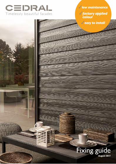
Fixing guide
CO
NT
ENT
S
3
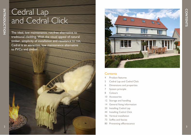
Cedral Lap and Cedral ClickThe ideal, low maintenance, rot-free alternative to traditional cladding. With the visual appeal of natural timber, simplicity of installation and resistance to rot, Cedral is an attractive, low maintenance alternative to PVCu and timber.
Contents4 Product features
5 Cedral Lap and Cedral Click
6 Dimensions and properties
7 System principle
8 Colours
10 Accessories
12 Storage and handling
14 General fixing information
20 Installing Cedral Lap
44 Installing Cedral Click
56 Vertical installation
73 Soffits and fascias
80 Preventing efflorescence2
INT
RO
DU
CT
ION
CED
RA
L LAP &
CED
RA
L CLIC
K
5
PRO
DU
CT
FEAT
UR
ES
4
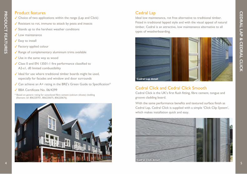
Cedral LapIdeal low maintenance, rot free alternative to traditional timber. Fitted in traditional lapped style and with the visual appeal of natural timber, Cedral is an attractive, low maintenance alternative to all types of weatherboarding.
Cedral Click and Cedral Click SmoothCedral Click is the UK’s first flush fitting, fibre cement, tongue and groove cladding board.
With the same performance benefits and textured surface finish as Cedral Lap, Cedral Click is supplied with a simple ‘Click Clip System’, which makes installation quick and easy.
Cedral Click detail
Product features✓ Choice of two applications within the range (Lap and Click)
✓ Resistant to rot, immune to attack by pests and insects
✓ Stands up to the harshest weather conditions
✓ Low maintenance
✓ Easy to install
✓ Factory applied colour
✓ Range of complementary aluminium trims available
✓ Use in the same way as wood
✓ Class 0 and EN 13501-1 fire performance classified to A2-s1, d0 limited combustibility
✓ Ideal for use where traditional timber boards might be used, especially for facades and window and door surrounds
✓ Can achieve an A+ rating in the BRE’s Green Guide to Specification*
✓ BBA Certificate No. 06/4299* Based on generic rating for autoclaved fibre cement (calcium silicate) cladding (Element ref. 806220701, 806220675, 806220676).
Cedral Lap detail
SYST
EM PR
INC
IPLE
7
DIM
ENSIO
NS &
PRO
PERT
IES
6
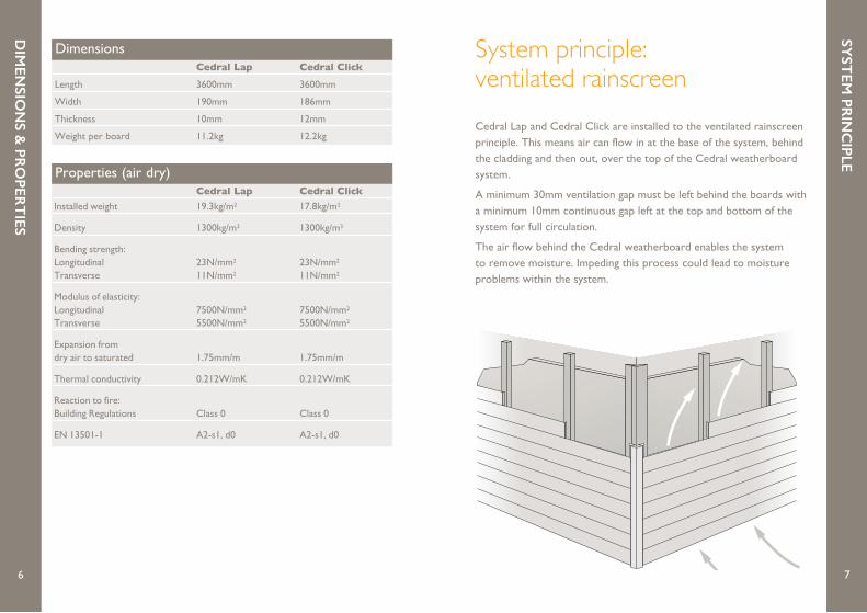
System principle: ventilated rainscreenCedral Lap and Cedral Click are installed to the ventilated rainscreen principle. This means air can flow in at the base of the system, behind the cladding and then out, over the top of the Cedral weatherboard system.
A minimum 30mm ventilation gap must be left behind the boards with a minimum 10mm continuous gap left at the top and bottom of the system for full circulation.
The air flow behind the Cedral weatherboard enables the system to remove moisture. Impeding this process could lead to moisture problems within the system.
Dimensions Cedral Lap Cedral Click Length 3600mm 3600mm
Width 190mm 186mm
Thickness 10mm 12mm
Weight per board 11.2kg 12.2kg
Properties (air dry) Cedral Lap Cedral Click Installed weight 19.3kg/m2 17.8kg/m2
Density 1300kg/m3 1300kg/m3
Bending strength: Longitudinal 23N/mm2 23N/mm2 Transverse 11N/mm2 11N/mm2
Modulus of elasticity: Longitudinal 7500N/mm2 7500N/mm2 Transverse 5500N/mm2 5500N/mm2
Expansion from dry air to saturated 1.75mm/m 1.75mm/m
Thermal conductivity 0.212W/mK 0.212W/mK
Reaction to fire: Building Regulations Class 0 Class 0
EN 13501-1 A2-s1, d0 A2-s1, d0

CO
LOU
RS
9
CO
LOU
RS
8
C03 Grey Brown
C14 Atlas Brown**
C55 Taupe**
C61 Burnt Red**
C104 Light Oak*
C105 Dark Oak*
Earth tones
C06 Grey Green**
C10 Blue Grey**
C62 Violet Blue**
C15 Dark Grey**
C18 Slate Grey
Ocean tones
C07 Cream White
C02 Beige
C08 Sand Yellow**
C57 Sage Green**
C60 Forest Grey**
C04 Dark Brown**
Forest tones
C01 White
C51 Silver Grey**
C05 Grey
C52 Pearl**
C54 Pewter**
C50 Black
Mineral tones
AvailabilityCedral Lap can be supplied in a range of 21 factory applied colours and 2 woodstain finishes providing an aesthetic option to suit most project requirements.
Cedral Click and Cedral Click Smooth finishes can be supplied in a range of 10 factory applied colours. Other colours within the range, bespoke colours and Cedral Click Smooth are subject to minimum order quantities and extended lead times.
All painted colours are available in a smooth finish for Cedral Lap and Cedral Click (subject to extended lead times).
Bespoke colours are subject to minimum order quantities and extended lead times.
WoodstainsCedral Lap is available in 2 woodstain shades designed to mimic the appearance of stained natural wood finish and as such, a variation in colour and shade is part of the effect inherent in the material design. The translucent finish will be accentuated by the effects of ambient light and viewing angle.
Due to transparent coating, it is not recommended to install Cedral Lap woodstain colours vertically.
* Not available in Cedral Click, Cedral Click Smooth or Cedral Lap Smooth.** Cedral Click in the colours identified may be subject to minimum order quantities and extended lead times.

AC
CESSO
RIES
Accessories
Touch up paint Cedral touch up paint is available in 0.5 litre quantities for all colours. This should be applied sparingly with a small brush, only where there is damage to paint or on cut edges.
Aluminium trimsSupplied in 3m lengths and colours to match and complement the Cedral range.
Cedral screwsThe use of Cedral colour matched screws is recommended for all visible fixings.
Click Clips and screwsThe use of Cedral Click Clips is required when installing Cedral Click. These are supplied complete with stainless steel screws in boxes of 250.
For your nearest stockist, visit www.cedral.co.uk
AC
CESSO
RIES
For your nearest stockist, visit www.cedral.co.uk10 11
STO
RA
GE &
HA
ND
LING
13
STO
RA
GE &
HA
ND
LING
12
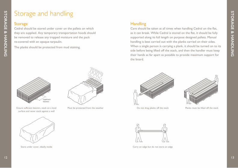
Storage and handlingStorageCedral should be stored under cover on the pallets on which they are supplied. Any temporary transportation hoods should be removed to release any trapped moisture and the pack re-covered with an opaque tarpaulin.
The planks should be protected from mud staining.
Ensure sufficient bearers, stack on a level surface and never stack against a wall
Must be protected from the weather
Store under cover, ideally inside
Do not drag planks off the stack Planks must be lifted off the stack
Carry on edge but do not store on edge
HandlingCare should be taken at all times when handling Cedral on the flat, as it can break. While Cedral is stored on the flat, it should be fully supported along its full length on purpose designed pallets. Manual handling is best carried out with the planks carried on their sides. When a single person is carrying a plank, it should be turned on to its side before being lifted off the stack, and then the handler must keep their hands as far apart as possible to provide maximum support for the board.
maximum400mm
maximum400mm
maximum400mm
maximum400mm
maximum400mm
maximum400mm
14
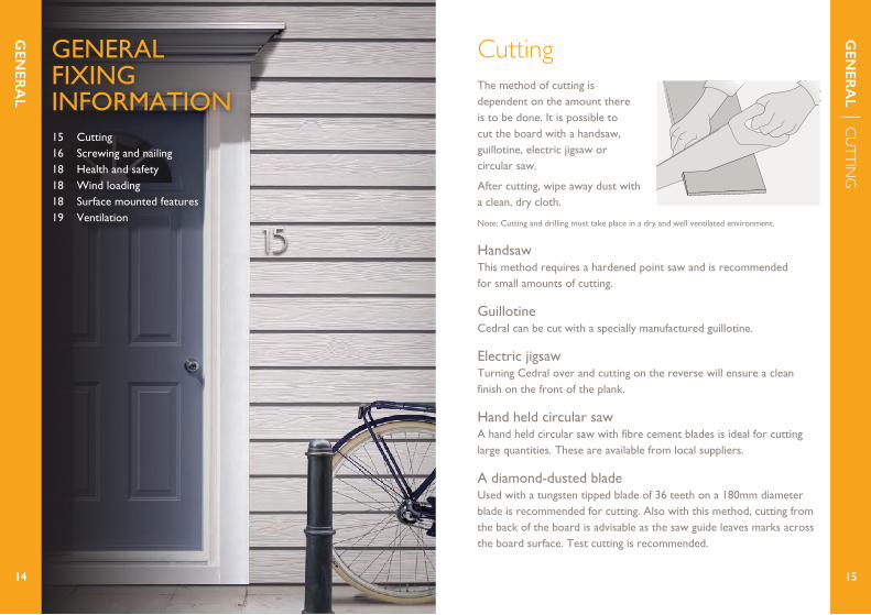
GENERALFIXING INFORMATION15 Cutting16 Screwing and nailing18 Health and safety 18 Wind loading 18 Surface mounted features 19 Ventilation
The method of cutting is dependent on the amount there is to be done. It is possible to cut the board with a handsaw, guillotine, electric jigsaw or circular saw.
After cutting, wipe away dust with a clean, dry cloth.
Note: Cutting and drilling must take place in a dry and well ventilated environment.
HandsawThis method requires a hardened point saw and is recommended for small amounts of cutting.
GuillotineCedral can be cut with a specially manufactured guillotine.
Electric jigsawTurning Cedral over and cutting on the reverse will ensure a clean finish on the front of the plank.
Hand held circular sawA hand held circular saw with fibre cement blades is ideal for cutting large quantities. These are available from local suppliers.
A diamond-dusted bladeUsed with a tungsten tipped blade of 36 teeth on a 180mm diameter blade is recommended for cutting. Also with this method, cutting from the back of the board is advisable as the saw guide leaves marks across the board surface. Test cutting is recommended.
GEN
ERA
L | CUTTIN
G
GEN
ERA
L
1514
Cutting
GEN
ERA
L | SCREWIN
G & N
AILING
16
GEN
ERA
L | SCREWIN
G & N
AILING
17
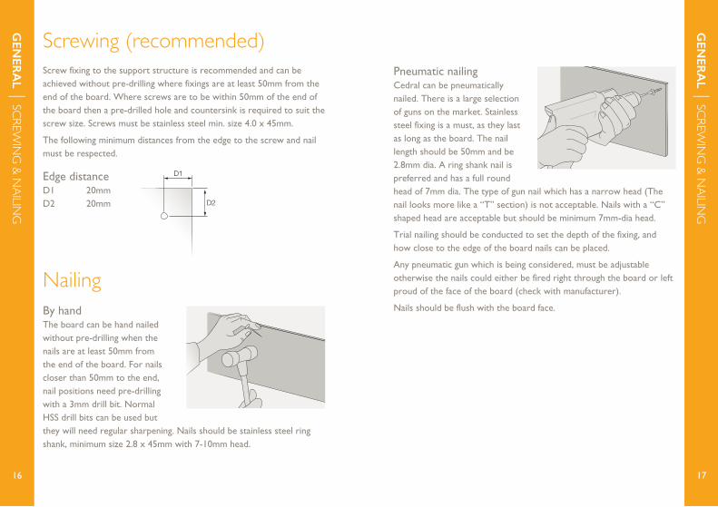
Screw fixing to the support structure is recommended and can be achieved without pre-drilling where fixings are at least 50mm from the end of the board. Where screws are to be within 50mm of the end of the board then a pre-drilled hole and countersink is required to suit the screw size. Screws must be stainless steel min. size 4.0 x 45mm.
The following minimum distances from the edge to the screw and nail must be respected.
Edge distanceD1 20mm D2 20mm
Screwing (recommended)
By handThe board can be hand nailed without pre-drilling when the nails are at least 50mm from the end of the board. For nails closer than 50mm to the end, nail positions need pre-drilling with a 3mm drill bit. Normal HSS drill bits can be used but they will need regular sharpening. Nails should be stainless steel ring shank, minimum size 2.8 x 45mm with 7-10mm head.
Nailing
D2
D1
Pneumatic nailingCedral can be pneumatically nailed. There is a large selection of guns on the market. Stainless steel fixing is a must, as they last as long as the board. The nail length should be 50mm and be 2.8mm dia. A ring shank nail is preferred and has a full round head of 7mm dia. The type of gun nail which has a narrow head (The nail looks more like a “T” section) is not acceptable. Nails with a “C” shaped head are acceptable but should be minimum 7mm-dia head.
Trial nailing should be conducted to set the depth of the fixing, and how close to the edge of the board nails can be placed.
Any pneumatic gun which is being considered, must be adjustable otherwise the nails could either be fired right through the board or left proud of the face of the board (check with manufacturer).
Nails should be flush with the board face.

GEN
ERA
L | OTH
ER CON
SIDERATIO
NS
18
GEN
ERA
L | OTH
ER CON
SIDERATIO
NS
19
Health & safetyDust can be released while the sheets are being processed which can irritate airways and eyes. Long-term exposure to dust can be harmful to health. For more information, please refer to the safety data sheet which can be found in the technical section for Cedral Lap at www.cedral.co.uk.
High wind loading; very severe/severe exposure or exceptional impact loading requirementsShould wind loading exceed 1.0kN/m2, or where the exposure is classed as ‘severe’ or ‘very severe’, please consult the Technical Department (01283 722588). Where exceptional impact loads to the Cedral planks can be anticipated (i.e. low level applications near pedestrian access, schools, leisure facilities etc.) additional timber battens should be incorporated, between the fixing battens, to increase the plank resistance.
Where other building features (i.e. signs, gutters, canopies etc.) are to be fixed then additional batten work should be included and clearance holes must be provided through Cedral. Under no circumstances should the Cedral planks receive additional structural loads.
Surface mounted features To avoid interstitial condensation, a minimum 30mm free flow cavity should be provided behind the Cedral with a minimum 10,000mm2/m run of ventilation at the top and bottom of the installation.
The use of 38mm deep battens will provide the necessary cavity and will be of minimum sufficiency to resist the pull-out loads generated by the planks.
Ventilation

INSTALLINGCEDRAL LAP21 Introduction22 Batten fixing23 Perforated closures25 Vertical profiles29 Horizontal profiles31 Fixing method 37 Corner options 41 Finishing and decoration42 Additional insulation
INST
ALLIN
G C
EDR
AL LA
P
INST
ALLIN
G C
EDR
AL LA
P | INTRO
DU
CTION
212020
There are a number of fixing variants for Cedral, but the general principle is the same for all.
Cedral needs to be fixed to vertical timber battens (preservative treated and planed on two faces) of at least 50mm wide, spaced at a maximum of 600mm across the elevation. Cedral should be fixed to at least three battens: if it is only fixed to two, then the batten spacing should be reduced to 400mm.
A minimum 30mm clear cavity must be provided behind Cedral with a 10mm continuous opening at the base, head and at the window and door heads and cills.
7 step installation procedure1. Fix battens to wall
2. Attach perforated closures to top and bottom of battens
3. Fix vertical profiles
4. Fix horizontal starter profiles
5. Cut and fix Cedral Lap planks
6. Corner options
7. Finishing and decoration

INST
ALLIN
G C
EDR
AL LA
P | PERFORATED
CLOSU
RES
23
INST
ALLIN
G C
EDR
AL LA
P | BATTEN FIX
ING
22
Position and fix the vertical battens*Battens to be spaced a maximum of 600mm apart (reduce this in high windload areas).
Batten sizes• Standard fixing – 50mm x 38mm • Joints/corners – 75mm x 38mm
* For solid walls, timber frame and metal stud constructions it is good practice to include a breathable membrane behind the battens. Generally for unfilled/partially filled cavity walls there is no requirement to do this.
Aluminium finish 2.5m length.
Perforated closures should be screwed or nailed to both the top and bottom of battens. They are designed to protect against birds, rodents and some insects while still allowing air to flow through the system.
Available in depths of 40mm, 50mm, 70mm and 100mm to allow for coverage of external insulation.
Perforated closures should also be attached to each door, cill and window head, to prevent animal and insect ingress whist allowing ventilation paths to be maintained.
Perforated closure
Perforated closuresBatten fixing
38 x 50mmtimber batten
Cedral Start profile
Cedral Perforated Closure
Free airflow
Cedral Lap
Cedral Connection Profile
Mastic joint
20mm minimum
Screw or nail
Cedral Lap
30mm 20mm
50 x 38mm min. timber battens600mm c/c max. fixed back to structure
Main structure
Metal flashingby others
Starter profile
30mm
30mm60mm
Nail or screw
Perforated closure
38 x 50mmtimber batten
Nail or screw
Starter profile
Cedral Lap
30mm
30mm
30mm
150mm 21mm
Perforated closure10mm
60mm
20mm
Main structure
INST
ALLIN
G C
EDR
AL LA
P | VERTICAL PROFILES
25
INST
ALLIN
G C
EDR
AL LA
P | PERFORATED
CLOSU
RES
24
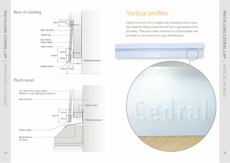
Base of cladding
Plinth detail
Cedral trims are 3m in length and manufactured to meet the required safety standards and have a guaranteed level of quality. They are colour matched to Cedral planks and branded on the reverse for easy identification.
Vertical profiles
Nail or screw fixingSymmetric corner profile
3mmexpansion gap
100 x 38mm timber batten
Nail or screw fixing
Cedral Lap
50 x 38mm timber batten
Main structure
Damp proof membrane
3mmexpansion joint
INST
ALLIN
G C
EDR
AL LA
P | VERTICAL PROFILES
27
INST
ALLIN
G C
EDR
AL LA
P | VERTICAL PROFILES
26
1mm
31mm 26mm
34mm34mm
26mm
31mm
35mm
35mm
25mm
25mm
1mm
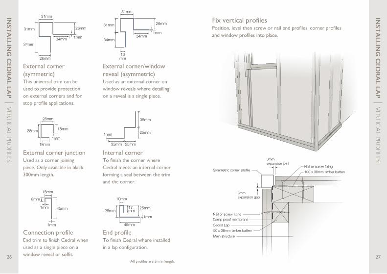
Fix vertical profilesPosition, level then screw or nail end profiles, corner profiles and window profiles into place.
External corner (symmetric)This universal trim can be used to provide protection on external corners and for stop profile applications.
Internal cornerTo finish the corner where Cedral meets an internal corner forming a seal between the trim and the corner.
End profileTo finish Cedral where installed in a lap configuration.
Connection profileEnd trim to finish Cedral when used as a single piece on a window reveal or soffit.
25mm
10mm
26mm
45mm
1mm
17mm
1mm
8mm
15mm
45mm1mm
External corner junctionUsed as a corner joining piece. Only available in black. 300mm length.
28mm
28mm
18mm
18mm
1mm
1mm
26mm31mm
34mm
13mm
31mm
34mm
External corner/window reveal (asymmetric)Used as an external corner on window reveals where detailing on a reveal is a single piece.
All profiles are 3m in length.
Asymmetriccorner profile
Nail or screw fixing
Cedral Lap
Nail or screw fixing
38 x 50mm treated batten
Connection profile
Mastic bead
3mm expansion joint
3mmexpansionjoint
Treated timber batten
3mm
Damp proof membrane
INST
ALLIN
G C
EDR
AL LA
P | HO
RIZON
TAL PROFILES
29
INST
ALLIN
G C
EDR
AL LA
P | VERTICAL PROFILES
28
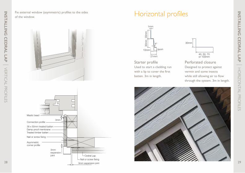
Fix external window (asymmetric) profiles to the sides of the window.
Starter profileUsed to start a cladding run with a lip to cover the first batten. 3m in length.
Perforated closureDesigned to protect against vermin and some insects while still allowing air to flow through the system. 3m in length.
1mm
30m
m30
mm
10mm
4°
21mm
9mm
30mm
40, 50, 70or 100mm
Horizontal profiles
38 x 50mmtimber batten
Nail or screw
Starter profile
150mm
Perforated closure
Main structure
INST
ALLIN
G C
EDR
AL LA
P | FIXIN
G M
ETHO
D
31
INST
ALLIN
G C
EDR
AL LA
P | HO
RIZON
TAL PROFILES
30
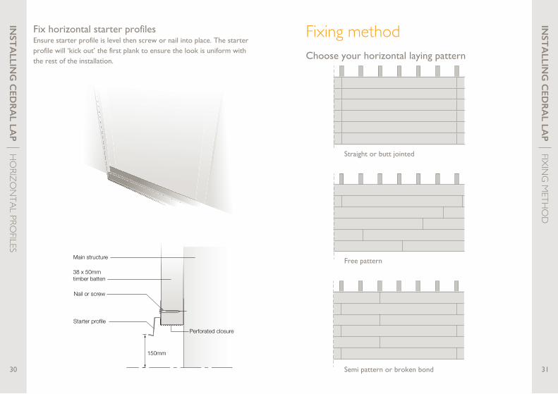
Fix horizontal starter profilesEnsure starter profile is level then screw or nail into place. The starter profile will ‘kick out’ the first plank to ensure the look is uniform with the rest of the installation.
Choose your horizontal laying pattern
Straight or butt jointed
Semi pattern or broken bond
Free pattern
Fixing method
INST
ALLIN
G C
EDR
AL LA
P | FIXIN
G M
ETHO
D
33
INST
ALLIN
G C
EDR
AL LA
P | FIXIN
G M
ETHO
D
32
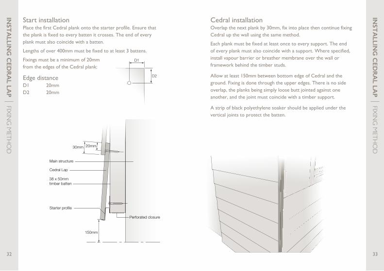
Start installationPlace the first Cedral plank onto the starter profile. Ensure that the plank is fixed to every batten it crosses. The end of every plank must also coincide with a batten.
Lengths of over 400mm must be fixed to at least 3 battens.
Fixings must be a minimum of 20mm from the edges of the Cedral plank:
D2
D1
Edge distanceD1 20mm D2 20mm
38 x 50mmtimber batten
Starter profile
Cedral Lap
30mm
150mm
Perforated closure
20mm
Main structure
Cedral installationOverlap the next plank by 30mm, fix into place then continue fixing Cedral up the wall using the same method.
Each plank must be fixed at least once to every support. The end of every plank must also coincide with a support. Where specified, install vapour barrier or breather membrane over the wall or framework behind the timber studs.
Allow at least 150mm between bottom edge of Cedral and the ground. Fixing is done through the upper edges. There is no side overlap, the planks being simply loose butt jointed against one another, and the joint must coincide with a timber support.
A strip of black polyethylene soaker should be applied under the vertical joints to protect the batten.

Jointing of CedralWhen two planks of Cedral are joined together and fixed to one batten, a protective strip should be placed onto the batten to guard against moisture ingress.
Planks should be loose butt jointed together, do not use force.
INST
ALLIN
G C
EDR
AL LA
P | FIXIN
G M
ETHO
D
35
INST
ALLIN
G C
EDR
AL LA
P | FIXIN
G M
ETHO
D
34
Finishing Cedral at top of wallWhen you get to the top plank, the fixings will remain visible. For best results use colour matched Cedral board screws.
Soffit detail
50 x 38mm min. timber battens 600mm c/c max. fixed backto structure
Main structure
Cedral Lap
Line of soffit
Perforated closure
30mm lap
Sloping soffit detail
25 x 50mm batten runningparallel with sloping soffit(to support end of boards)
50 x 38mm min. timber battens 600mm c/c max. fixed backto structure
Main structure
Cedral Lap
Line of sloping soffit(gables)
Perforated closure
30mm lap
13 x 50 x 75mm packing at each batten position
INST
ALLIN
G C
EDR
AL LA
P | CORN
ER OPTIO
NS
37
INST
ALLIN
G C
EDR
AL LA
P | FIXIN
G M
ETHO
D
36
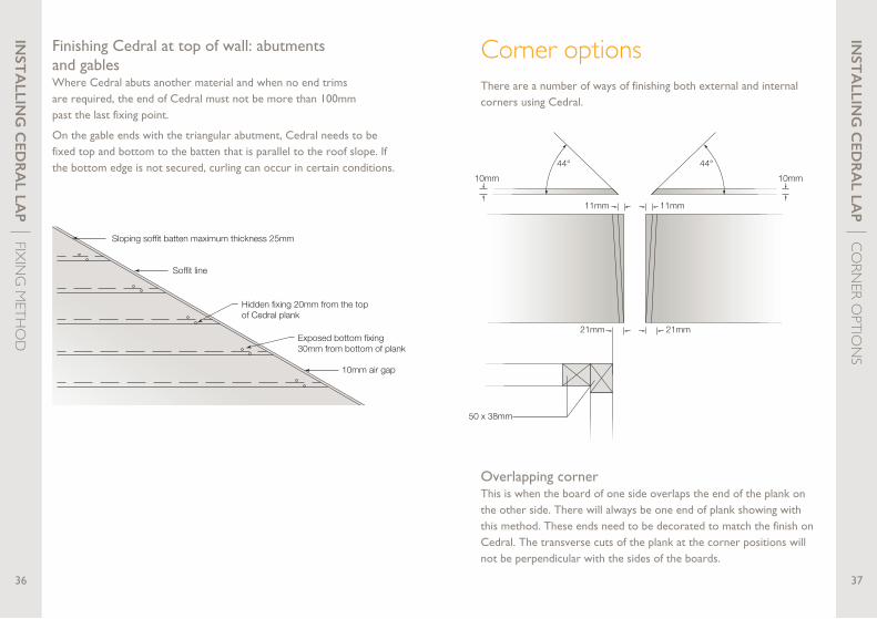
Finishing Cedral at top of wall: abutments and gablesWhere Cedral abuts another material and when no end trims are required, the end of Cedral must not be more than 100mm past the last fixing point.
On the gable ends with the triangular abutment, Cedral needs to be fixed top and bottom to the batten that is parallel to the roof slope. If the bottom edge is not secured, curling can occur in certain conditions.
There are a number of ways of finishing both external and internal corners using Cedral.
Overlapping cornerThis is when the board of one side overlaps the end of the plank on the other side. There will always be one end of plank showing with this method. These ends need to be decorated to match the finish on Cedral. The transverse cuts of the plank at the corner positions will not be perpendicular with the sides of the boards.
Sloping soffit batten maximum thickness 25mm
Soffit line
Hidden fixing 20mm from the top of Cedral plank
Exposed bottom fixing 30mm from bottom of plank
10mm air gap
50 x 38mm
44°44°
10mm
11mm
10mm
21mm21mm
11mm
Main structure
Cedral Lap
Mitred corner
Damp proofmembrane
50 x 38mmtimber battens
Corner options
3mmexpansiongap
3mmexpansiongap
Nail or screw fixed
Internal corner profile
Damp proof membrane
38 x 50mm treated batten
Cedral Lap
Nail or screw fixed
38 x 50mm treated batten
Nail or screw fixing
Cedral Weatherboard
38 x 50mmtreated batten
End Profile (refer todrawing number WB05 fordetails).
Mastic bead
3mmexpansion gap
Compressiblefoam strip
Damp proof membrane
INST
ALLIN
G C
EDR
AL LA
P | CORN
ER OPTIO
NS
3938
50 x 38mm
44°44°
10mm
11mm
10mm
21mm21mm
11mm
Main structure
Cedral Lap
Mitred corner
Damp proofmembrane
50 x 38mmtimber battens
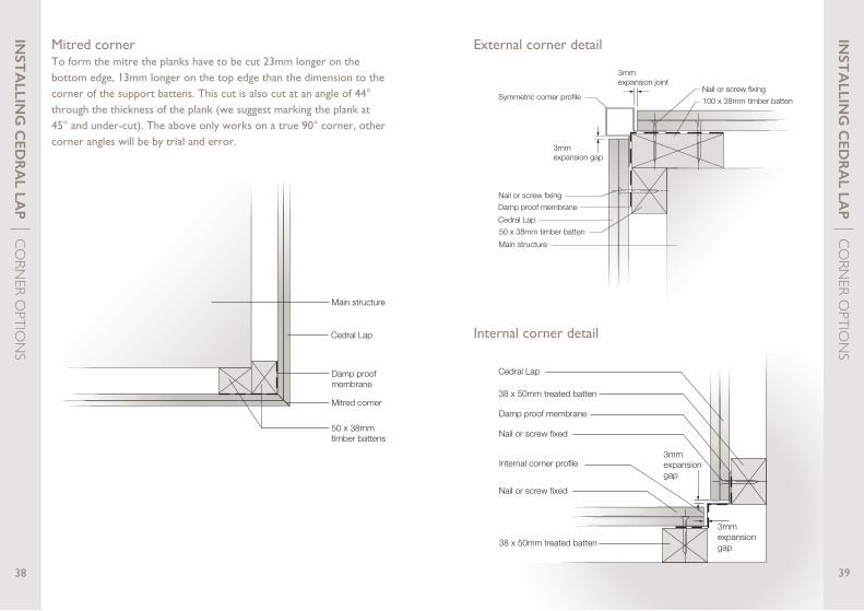
Mitred cornerTo form the mitre the planks have to be cut 23mm longer on the bottom edge, 13mm longer on the top edge than the dimension to the corner of the support battens. This cut is also cut at an angle of 44° through the thickness of the plank (we suggest marking the plank at 45° and under-cut). The above only works on a true 90° corner, other corner angles will be by trial and error.
External corner detail
Internal corner detail
Nail or screw fixingSymmetric corner profile
3mmexpansion gap
100 x 38mm timber batten
Nail or screw fixing
Cedral Lap
50 x 38mm timber batten
Main structure
Damp proof membrane
3mmexpansion joint
INST
ALLIN
G C
EDR
AL LA
P | CORN
ER OPTIO
NS
Nail or screw fixing
Cedral Lap
38 x 50mm treated batten
End profile
Mastic bead 3mmexpansion gap
Compressiblefoam strip
Damp proof membrane
INST
ALLIN
G C
EDR
AL LA
P | FINISH
ING
& DECO
RATION
41
INST
ALLIN
G C
EDR
AL LA
P | CORN
ER OPTIO
NS
40
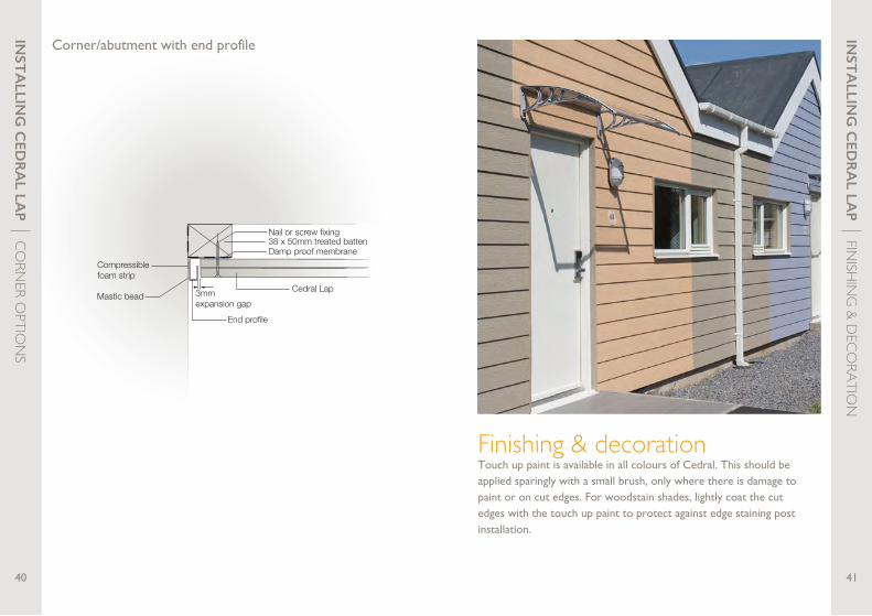
Corner/abutment with end profile
Finishing & decorationTouch up paint is available in all colours of Cedral. This should be applied sparingly with a small brush, only where there is damage to paint or on cut edges. For woodstain shades, lightly coat the cut edges with the touch up paint to protect against edge staining post installation.

INST
ALLIN
G C
EDR
AL LA
P | ADD
ITION
AL INSU
LATION
43
INST
ALLIN
G C
EDR
AL LA
P | ADD
ITION
AL INSU
LATION
42
Securely fix horizontal battens on wall/substrate*These will accommodate any insulation required and also support the vertical battens to which the Cedral planks will be fixed.
Fix insulation to the wall between the battens or angle bracketsMake sure there are no gaps. Alternatively, use adjustable wall brackets to fix battens if greater thickness of insulation is required. Vertical battens will then be fitted on top of the horizontal battens.
Adjustable wall bracket
Should insulation be required, additional cavity depth can be gained with the use of cross battens or adjustable brackets.
* For solid walls, timber frame and metal stud constructions it is good practice to include a breathable membrane behind the battens. Generally for unfilled/partially filled cavity walls there is no requirement to do this.
Additional insulation
INST
ALLIN
G C
EDR
AL C
LICK | IN
TOD
UCTIO
N
4544
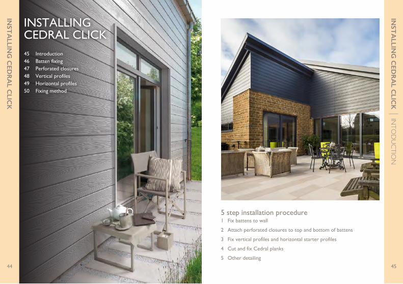
5 step installation procedure1 Fix battens to wall
2 Attach perforated closures to top and bottom of battens
3 Fix vertical profiles and horizontal starter profiles
4 Cut and fix Cedral planks
5 Other detailing
44
INSTALLING CEDRAL CLICK45 Introduction46 Batten fixing47 Perforated closures48 Vertical profiles 49 Horizontal profiles50 Fixing method
INST
ALLIN
G C
EDR
AL C
LICK
44

INST
ALLIN
G C
EDR
AL C
LICK | PERFO
RATED CLO
SURES
47
INST
ALLIN
G C
EDR
AL C
LICK | BATTEN
FIXIN
G
46
Position and fix the vertical battens. Battens to be spaced a maximum of 600mm apart (reduce this in high windload areas).
Batten sizes• Standard fixing – 75mm x 38mm
• Joints/Corners – 100mm x 38mm
Perforated closures should be screwed or nailed to the top and bottom of battens for each door, cill and window head.
They are designed to protect against birds, rodents and some insects while still allowing air to flow through the system.
Available in depths of 40mm, 50mm, 70mm and 100mm to allow for coverage of external insulation.
Perforated closure
Perforated closuresBatten fixing

INST
ALLIN
G C
EDR
AL C
LICK | H
ORIZO
NTAL PRO
FILES
49
INST
ALLIN
G C
EDR
AL C
LICK | VERTICAL PRO
FILES
48
Internal cornerTo finish the corner where Cedral meets on an internal corner forming a seal between the trim and the corner.
35mm
35mm
14mm
14mm
1mm
54mm
16mm
Window lintel profileUsed to finish above the window and to support the next course of Cedral Click.
Starter profileUsed at base of the external wall. Installed absolutely level to ensure installation of Cedral Click panels remains perfectly parallel.
10
10
15
40 46.5
3.5
3
8
1
External corner/ window revealCan be used as an external corner or where detailing on a window reveal.
1mm
20mm 15mm
34mm34mm
15mm
20mm
Connection profileEnd trim to finish Cedral when used as a single piece on a window reveal or soffit.
1mm
8mm
15mm
45mm1mm
Fix horizontal profilesFix vertical profiles
INST
ALLIN
G C
EDR
AL C
LICK | FIX
ING
METH
OD
51
INST
ALLIN
G C
EDR
AL C
LICK | FIX
ING
METH
OD
50
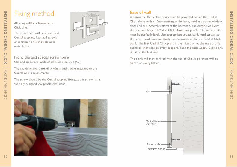
Fixing clip and special screw fixingClip and screw are made of stainless steel 304 (A2).
The clip dimensions are: 60 x 40mm with hooks matched to the Cedral Click requirements.
The screw should be the Cedral supplied fixing, as this screw has a specially designed low profile (flat) head.
All fixing will be achieved with Click clips.
These are fixed with stainless steel Cedral supplied, flat-head screws onto timber or with rivets onto metal frame.
Starter profile
Vertical timbermin 70x38
Clip
Perforated closure
Base of wallA minimum 30mm clear cavity must be provided behind the Cedral Click planks with a 10mm opening at the base, head and at the window, door and cills. Assembly starts at the bottom of the outside wall with the purpose designed Cedral Click plank start profile. The start profile must be perfectly level. Use appropriate countersunk head screws so the screw head does not block the placement of the first Cedral Click plank. The first Cedral Click plank is then fitted on to the start profile and fixed with clips on every support. Then the next Cedral Click plank is put on the first one.
The plank will then be fixed with the use of Click clips, these will be placed on every batten.
Fixing method

Connection profile
Cedral Click
Cedral Click clip
Soaker
Corner profile
Timber battenmin 70x38
3mm gap
3mm gap
INST
ALLIN
G C
EDR
AL C
LICK | FIX
ING
METH
OD
53
INST
ALLIN
G C
EDR
AL C
LICK | FIX
ING
METH
OD
52
Cedral
≤60
≥70
35 35
≥5
The distance from the edge of the Click Clip to the edge of the Cedral plank should not exceed 60mm
Continued installationThe Cedral Click planks are placed with the ends against each other and always on top of an underlying supporting batten.
Not only behind the joints, but the entire wooden supporting battens are protected by a joint sealing strip with sufficient stiffness. Because the joint sealing strip is not exposed to light, a black polyethylene (PE) 0.5 mm-thick joint sealing strip is sufficient. If the joint sealing strip is exposed to light, a UV-resistant material such as EPDM must be used.
Window detailing and external cornerThe vertical reveal sides of a window can be finished with the Cedral Click external corner profile. At the window head, the lintel profile can be used. This lintel profile can be used with whole Cedral Click planks or with cut planks. Holes in the lower part of the back of the profile prevent water pooling in the profile.
3mm expansion
gap
3mmexpansiongap
Internal corner profile
Damp proof membrane
Cedral Click
Cedral Click Clip
Timber battenmin. 70 x 38mm
INST
ALLIN
G C
EDR
AL C
LICK | FIX
ING
METH
OD
55
INST
ALLIN
G C
EDR
AL C
LICK | FIX
ING
METH
OD
54
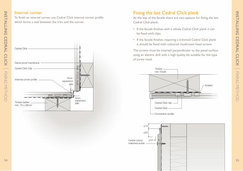
Internal cornerTo finish an internal corner, use Cedral Click internal corner profile which forms a seal between the trim and the corner.
≥10
≥10
≥30
Vertical timbermin 70x38
Cedral colour matched screw
Soaker at panel
Fixing the last Cedral Click plankAt the top of the facade there are two options for fixing the last Cedral Click plank:
• If the facade finishes with a whole Cedral Click plank it can be fixed with clips.
• If the facade finishes requiring a trimmed Cedral Click plank it should be fixed with coloured mushroom head screws.
The screws must be inserted perpendicular to the panel surface using an electric drill with a high quality bit suitable for the type of screw head.
Timbermin 70x38
Connection profile
Cedral Click
Cedral Click clip
Soaker

VERTICAL INSTALLATION OF CEDRAL57 Introduction58 Lay of planks59 Install timber battens60 Perforated closures61 Fix profiles68 Fixing method
VER
TIC
AL IN
STA
LLAT
ION
A ventilated rainscreen cladding system must be fixed onto battens to allow an air gap behind the cladding.
With a traditional horizontal installation of Cedral only vertical battens would be needed.
To install Cedral vertically, vertical battens must be installed first, with horizontal counter battens then placed on top. This allows the air gap behind the cladding while giving a fixing point.
Please note: A minimum air gap of 10mm must be left at the top and bottom of all sections to allow air to flow completely through the system.
Horizontal Vertical
VER
TIC
AL IN
STA
LLAT
ION
| INTRO
DU
CTION
5756
Passageof air
Passageof air
Ventilated rainscreen system
5 step installation procedure1 Decide on the ‘lay’ of the Cedral planks
2 Install timber battens
3 Fix perforated closures
4 Fix profiles
5 Install Cedral planks
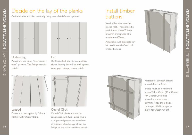
Vertical battens must be placed first. These must be a minimum size of 25mm x 50mm and spaced at a maximum 600mm.
Adjustable wall brackets can be used instead of vertical timber battens.
Horizontal counter battens should then be fixed.
These must be a minimum size of 38 x 50mm (38 x 75mm for Cedral Click) and spaced at a maximum 600mm. They should also be trapezoidal in shape to allow for water run off.
VER
TIC
AL IN
STA
LLAT
ION
| TIMBER BATTEN
S
59
VER
TIC
AL IN
STA
LLAT
ION
| LAY OF PLAN
KS
58
Cedral can be installed vertically using one of 4 different options:
UndulatingPlanks are laid in an “over under over” pattern. The fixings remain visible.
70mm Fixings min.
20mm from edge of plank
Overlap planks by60mm
FlatPlanks are laid next to each other, either loosely butted or with up to a 2mm gap. Fixings remain visible.
Fixings min. 20mmfrom edge of plank
0-2mm uniform gap between planks
LappedPlanks are overlapped by 30mm. Fixings will remain visible.
Cedral ClickCedral Click planks are used in
conjunction with Click Clips. This is
a tongue and groove system where
all fixings are hidden apart from the
fixings on the starter and final boards.
Decide on the lay of the planks Install timber battens
VER
TIC
AL IN
STA
LLAT
ION
| FIX PRO
FILES
61
VER
TIC
AL IN
STA
LLAT
ION
| PERFORATED
CLOSU
RES
60
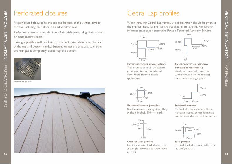
Fix perforated closures to the top and bottom of the vertical timber battens, including each door, cill and window head.
Perforated closures allow the flow of air while preventing birds, vermin or pests gaining access.
If using adjustable wall brackets, fix the perforated closure to the rear of the top and bottom vertical battens. Adjust the brackets to ensure the rear gap is completely closed top and bottom.
Perforated closure
1mm
31mm 26mm
34mm34mm
26mm
31mm
35mm
35mm
25mm
25mm
1mm
External corner (symmetric)This universal trim can be used to provide protection on external corners and for stop profile applications.
Internal cornerTo finish the corner where Cedral meets an internal corner forming a seal between the trim and the corner.
End profileTo finish Cedral where installed in a lap configuration.
Connection profileEnd trim to finish Cedral when used as a single piece on a window reveal or soffit.
25mm
10mm
26mm
45mm
1mm
17mm
1mm
8mm
15mm
45mm1mm
External corner junctionUsed as a corner joining piece. Only available in black. 300mm length.
28mm
28mm
18mm
18mm
1mm
1mm
26mm31mm
34mm
13mm
31mm
34mm
External corner/window reveal (asymmetric)Used as an external corner on window reveals where detailing on a reveal is a single piece.
Perforated closures Cedral Lap profilesWhen installing Cedral Lap vertically, consideration should be given to the profiles used. All profiles are supplied in 3m lengths. For further information, please contact the Facade Technical Advisory Service.
VER
TIC
AL IN
STA
LLAT
ION
| FIX PRO
FILES
63
VER
TIC
AL IN
STA
LLAT
ION
| FIX PRO
FILES
62
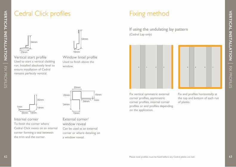
Internal cornerTo finish the corner where Cedral Click meets on an internal corner forming a seal between the trim and the corner.
35mm
35mm
14mm
14mm
1mm
54mm
16mm
Window lintel profileUsed to finish above the window.
Vertical start profileUsed to start a vertical cladding run. Installed absolutely level to ensure installation of Cedral remains perfectly vertical.
External corner/ window revealCan be used as an external corner or where detailing on a window reveal.
1mm
20mm 15mm
34mm34mm
15mm
20mm
If using the undulating lay pattern(Cedral Lap only)
70mm Fixings min.
20mm from edge of plank
Overlap planks by60mm
70mm Fixings min.
20mm from edge of plank
Overlap planks by60mm
Fix vertical symmetric external corner profiles, asymmetric corner profiles, internal corner profiles or end profiles depending on the application.
70mm Fixings min.
20mm from edge of plank
Overlap planks by60mm
Fix end profiles horizontally at the top and bottom of each run of planks.
Please note profiles must be fixed before any Cedral planks are laid.
34mm
23mm
Cedral Click profiles Fixing method

VER
TIC
AL IN
STA
LLAT
ION
| FIX PRO
FILES
65
VER
TIC
AL IN
STA
LLAT
ION
| FIX PRO
FILES
64 Please note profiles must be fixed before any Cedral planks are laid. Please note profiles must be fixed before any Cedral planks are laid.
If using the flat lay pattern(Cedral Lap only)
Fixings min. 20mmfrom edge of plank
0-2mm uniform gap between planks
Fix vertical connection profiles, click external corner profiles or lap external corner profiles.
Fixings min. 20mmfrom edge of plank
0-2mm uniform gap between planks
Fix horizontal connection profiles to the top and bottom of each section of planks.
Fixings min. 20mmfrom edge of plank
0-2mm uniform gap between planks
If using the lapped lay pattern(Cedral Lap only)
Install horizontal end profiles at the top and bottom of each section of cedral planks.
Fix vertical symmetric external corner profiles, asymmetric corner profiles, internal corner profiles or end profiles depending on the application.
Fix starter profiles where required to kick the first board of each run out to make it uniform with the rest.
6766
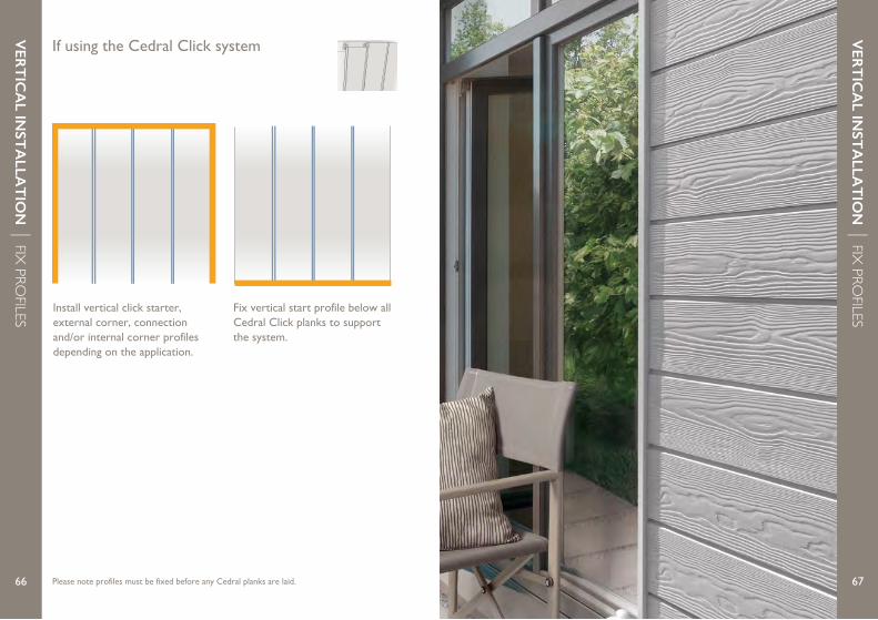
If using the Cedral Click system
Install vertical click starter, external corner, connection and/or internal corner profiles depending on the application.
Fix vertical start profile below all Cedral Click planks to support the system.
Please note profiles must be fixed before any Cedral planks are laid.
VER
TIC
AL IN
STA
LLAT
ION
| FIX PRO
FILES
VER
TIC
AL IN
STA
LLAT
ION
| FIX PRO
FILES
Fixings min. 20mmfrom edge of plank
0-2mm uniform gap between planks
Fixings min. 20mmfrom edge of plank
0-2mm uniform gap between planks
Fixings min. 20mmfrom edge of plank
0-2mm uniform gap between planks
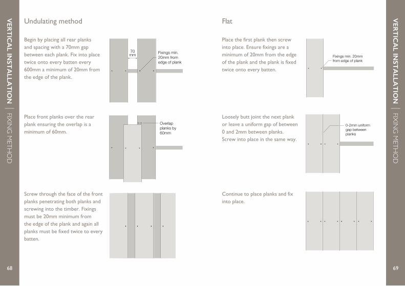
Flat
Place the first plank then screw into place. Ensure fixings are a minimum of 20mm from the edge of the plank and the plank is fixed twice onto every batten.
Loosely butt joint the next plank or leave a uniform gap of between 0 and 2mm between planks. Screw into place in the same way.
Continue to place planks and fix into place.
70mm Fixings min.
20mm from edge of plank
Overlap planks by60mm
70mm Fixings min.
20mm from edge of plank
Overlap planks by60mm
70mm Fixings min.
20mm from edge of plank
Overlap planks by60mm
6968
Undulating method
Begin by placing all rear planks and spacing with a 70mm gap between each plank. Fix into place twice onto every batten every 600mm a minimum of 20mm from the edge of the plank.
Screw through the face of the front planks penetrating both planks and screwing into the timber. Fixings must be 20mm minimum from the edge of the plank and again all planks must be fixed twice to every batten.
Place front planks over the rear plank ensuring the overlap is a minimum of 60mm.
VER
TIC
AL IN
STA
LLAT
ION
| FIXIN
G M
ETHO
D
VER
TIC
AL IN
STA
LLAT
ION
| FIXIN
G M
ETHO
D
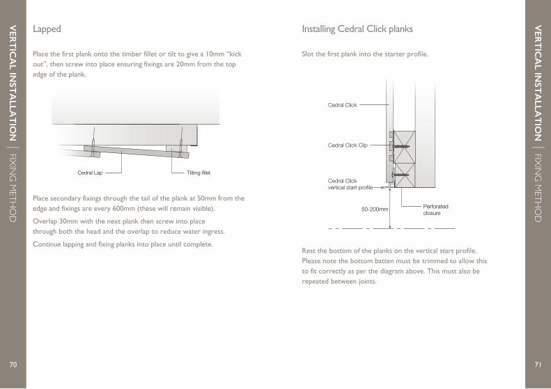
Cedral Lap 50mm
Cedral Lap Tilting fillet
7170
Lapped
Place the first plank onto the timber fillet or tilt to give a 10mm “kick out”, then screw into place ensuring fixings are 20mm from the top edge of the plank.
Installing Cedral Click planks
Place secondary fixings through the tail of the plank at 50mm from the edge and fixings are every 600mm (these will remain visible).
Overlap 30mm with the next plank then screw into place through both the head and the overlap to reduce water ingress.
Continue lapping and fixing planks into place until complete.
Slot the first plank into the starter profile.
Rest the bottom of the planks on the vertical start profile. Please note the bottom batten must be trimmed to allow this to fit correctly as per the diagram above. This must also be repeated between joints.
Cedral Click vertical start profile
Cedral Click
Cedral Click Clip
50-200mm Perforated closure
VER
TIC
AL IN
STA
LLAT
ION
| FIXIN
G M
ETHO
D
VER
TIC
AL IN
STA
LLAT
ION
| FIXIN
G M
ETHO
D
SOFFIT
S AN
D FA
SCIA
S
7372
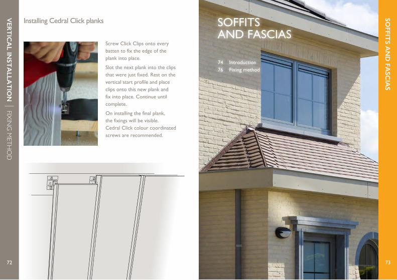
Installing Cedral Click planks
Screw Click Clips onto every batten to fix the edge of the plank into place.
Slot the next plank into the clips that were just fixed. Rest on the vertical start profile and place clips onto this new plank and fix into place. Continue until complete.
On installing the final plank, the fixings will be visible. Cedral Click colour coordinated screws are recommended.
SOFFITS AND FASCIAS
74 Introduction76 Fixing method
VER
TIC
AL IN
STA
LLAT
ION
| FIXIN
G M
ETHO
D

7574
SOFFIT
S AN
D FA
SCIA
S | INTRO
DU
CTION
SOFFIT
S AN
D FA
SCIA
S | INTRO
DU
CTION
Cedral Board can be used for soffits and fascias if attached to aligned supporting battens.
Ventilation is assured by using:
1 Vertical supporting battens.
2 Horizontal supporting battens combined with ventilation blocks, ventilation battens or ventilation profiles.
Example 1Soffit and fascia at typical gable end attached with screws on ventilation blocks.
Example 2Attachment on vertical supporting battens. The vertical battens must be thick enough to withstand wind pressure.
Example 3Renovation using ventilation battens.
≥30 5
5
≥30 5
5
30
≥30 5
5
≥30 5
5≥30 5
5
≥30 5
5
≥30 5
5
30
≥30 5
5
≥30 5
5≥30 5
5
Introduction
7574

7776
Maximum fixing distance Screwed
Land 0-20m Coast 0-20m
Multiple span
Centre area facade 600mm 500mm
Edge area facade soffit 500mm 400mm
Bottom of soffit 400mm 400mm
Single span
Centre area facade 500mm 400mm
Edge area facade soffit 400mm 400mm
Bottom of soffit 400mm 400mm
SOFFIT
S AN
D FA
SCIA
S | FIXIN
G M
ETHO
D
SOFFIT
S AN
D FA
SCIA
S | FIXIN
G M
ETHO
D
7776
Cedral Board fascias and soffits can be screw fixed. As a general rule, the following maximum distances between the fixing accessories must be maintained.
Fixing method
Visible fixing using screwsCedral Boards can be fixed by means of a stainless steel (quality A2, AISI 304) panel screw with coloured TORX T20 recessed head to the wooden supporting battens.
Screws are inserted using an electric drill with a high quality bit suitable for the type of screw head.
Screws must be inserted perpendicular to the panel surface, and may not be over-tightened so that the free expansion of the panel not is impeded.
This is achieved by limiting the moment setting of the drill
1 Minimum screw depth in supporting battens: 25 mm
2 Minimum distance from screw edge in supporting battens: 15 mm
≥15
≥38
≥25
90
L
12 4.8
Edge distancesThe following minimum and maximum distances from the edges of the fastening accessories must be respected. Drilling the holes can be done using a template.
D2
D1
Edge distanceD1 20mm D2 20mm
7978
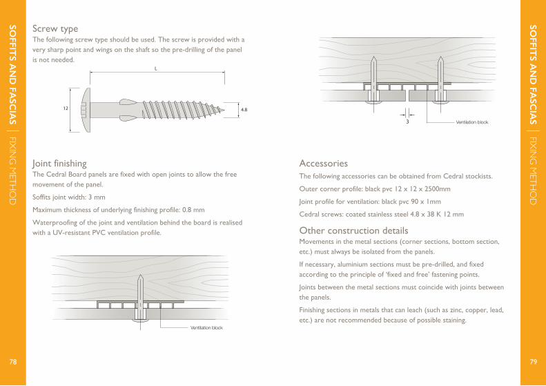
Screw typeThe following screw type should be used. The screw is provided with a very sharp point and wings on the shaft so the pre-drilling of the panel is not needed.
≥15
≥38
≥25
90
L
12 4.8
SOFFIT
S AN
D FA
SCIA
S | FIXIN
G M
ETHO
D
SOFFIT
S AN
D FA
SCIA
S | FIXIN
G M
ETHO
D
7978
Joint finishingThe Cedral Board panels are fixed with open joints to allow the free movement of the panel.
Soffits joint width: 3 mm
Maximum thickness of underlying finishing profile: 0.8 mm
Waterproofing of the joint and ventilation behind the board is realised with a UV-resistant PVC ventilation profile.
3
3
Ventilation block
Ventilation block
AccessoriesThe following accessories can be obtained from Cedral stockists.
Outer corner profile: black pvc 12 x 12 x 2500mm
Joint profile for ventilation: black pvc 90 x 1mm
Cedral screws: coated stainless steel 4.8 x 38 K 12 mm
Other construction detailsMovements in the metal sections (corner sections, bottom section, etc.) must always be isolated from the panels.
If necessary, aluminium sections must be pre-drilled, and fixed according to the principle of ‘fixed and free’ fastening points.
Joints between the metal sections must coincide with joints between the panels.
Finishing sections in metals that can leach (such as zinc, copper, lead, etc.) are not recommended because of possible staining.
PREV
ENT
ING
EFFLOR
ESCEN
CE
81
PREV
ENT
ING
EFFLOR
ESCEN
CE
80
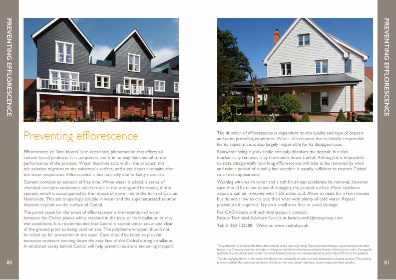
Efflorescence or ‘lime bloom’ is an occasional phenomenon that affects all cement-based products. It is temporary and is in no way detrimental to the performance of the product. Water dissolves salts within the product, this salt solution migrates to the substrate’s surface, and a salt deposit remains after the water evaporates. Efflorescence is not normally due to faulty materials.
Cement contains an amount of free lime. When water is added, a series of chemical reactions commence which result in the setting and hardening of the cement, which is accompanied by the release of more lime in the form of Calcium Hydroxide. This salt is sparingly soluble in water and the supersaturated solution deposits crystals on the surface of Cedral.
The prime cause for the onset of efflorescence is the retention of water between the Cedral planks whilst retained in the pack or its installation in very wet conditions. It is recommended that Cedral is stored under cover and clear of the ground prior to being used on site. The polythene wrapper should not be relied on for protection in the open. Care should be taken to prevent excessive moisture running down the rear face of the Cedral during installation. A ventilated cavity behind Cedral will help prevent moisture becoming trapped.
The duration of efflorescence is dependent on the quality and type of deposit and upon prevailing conditions. Water, the element that is initially responsible for its appearance, is also largely responsible for its disappearance.
Rainwater being slightly acidic not only dissolves the deposit, but also mechanically removes it by movement down Cedral. Although it is impossible to state categorically how long efflorescence will take to be removed by wind and rain; a period of suitably bad weather is usually sufficient to restore Cedral to an even appearance.
Washing with warm water and a soft brush can accelerate its removal, however care should be taken to avoid damaging the painted surface. More stubborn deposits can be removed with 9.5% acetic acid. Allow to react for a few minutes but do not allow to dry out, then wash with plenty of cold water. Repeat procedure if required. Try on a small area first to avoid damage.
For CAD details and technical support, contact: Facade Technical Advisory Service at [email protected]
Tel: 01283 722588 Website: www.cedral.co.uk
This publication is based on the latest data available at the time of printing. Due to product changes, improvements and other factors, the Company reserves the right to change or withdraw information contained herein without prior notice. For specific applications users should refer to the Technical Advisory Service and relevant Standards and Codes of Practice for guidance.
The photography shown in the document should not necessarily be taken as recommendations of good practice. The printing process restricts the exact representation of colours. For true colour reference, please request product samples.
Preventing efflorescence
NO
TES
83
NO
TES
82
Notes
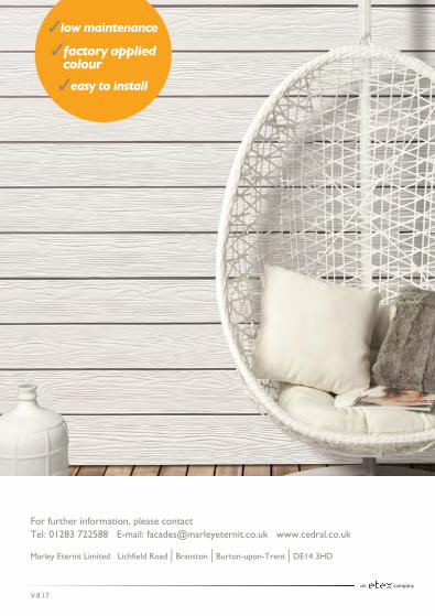
For further information, please contactTel: 01283 722588 E-mail: [email protected] www.cedral.co.uk
Marley Eternit Limited Lichfield Road | Branston | Burton-upon-Trent | DE14 3HD
V-8.17