Fixed-Speed and Variable Speed (PMSG) Induction … · G.Pradeep Kumar Reddy & Smt S.D.S.Bhagyamma...
12
International Journal of Emerging Engineering Research and Technology Volume 2, Issue 3, June 2014, PP 261-272 ISSN 2349-4395 (Print) & ISSN 2349-4409 (Online) ©IJEERT www.ijeert.org 261 Fixed-Speed and Variable Speed (PMSG) Induction Generators Based Wind Farms with Statcom Control under Asymmetrical Grid Faults G.Pradeep Kumar Reddy 1 , Smt S.D.S.Bhagyamma 2 1 M.Tech Scholor, 2 Assistant professor, Department of Electrical and Electronics Engineering, N.B.K.R.I.S.T, Nellore, A.P, India. Abstract: Recently, renewable wind energy is enjoying a rapid growth globally to become an important green electricity source to replace polluting and exhausting fossil fuel. The stability of fixed-speed induction generator (FSIG)-based wind turbines can be improved by a StatCom, which is well known and documented in the literature for balanced grid voltage dips and comparing with the variable speed permanent magnet synchronous machine. Under unbalanced grid voltage dips, the negative sequence voltage causes heavy generator torque oscillations that reduce the lifetime of the drive train. In my project, investigations on an FSIG-based wind farm in combination with a StatCom and variable speed permanent magnet synchronous machine under unbalanced grid voltage fault are carried out by means of theory, simulations. A StatCom control structure with the capability to coordinate the control between the positive and the negative sequence of the grid voltage is proposed. The results clarify the effect of the positive- and the negative-sequence voltage compensation by a StatCom on the operation of the FSIG-based wind farm and variable speed pmsg. With first priority, the StatCom ensures the maximum fault-ride-through enhancement of the wind farm by compensating the positive- sequence voltage. The remaining StatCom current capability of the StatCom is controlled to compensate the negative-sequence voltage, in order to reduce the torque oscillations. This total project is carried out in MATLAB SIMULINK software. Keywords: Matlab/Simulink , wind energy, Induction generator, low-voltage ride through, StatCom 1. I NTRODUCTION With the progress of industrial society and the increasing needs for energy and especially electrical energies and increasing environmental and economical concerns and Concerns about the ending of fossil energy resources in the world using of wind energy to generate electricity has been widely considered word-wide and wind generator in large scale has been installed. For optimal utilization and expecting outputs of such generators one of the fundamental topic is the system simulation and modeling error conditions. WIND energy is playing a key role on the way toward a sustainable energy future. Among the generator types used for wind turbines, the technical development has moved from fixed-speed to variable-speed concepts [1]. Although a major part of the newly installed wind turbines are of the variable-speed type using either a doubly fed induction generator (DFIG) or permanent-magnet synchronous generator, a non negligible percentage of 15% of the operating wind turbines in Europe in 2010 [2] is still of the fixed-speed induction generator (FSIG)-type directly connected to the grid. New industrial applications require variable speed drives with high dynamic performance. In recent years several techniques of control have been developed, allowing PMSM with variable speed to achieve these performances. It gives high dynamic performance for a wide range of applications. The complexity of the dynamic model of the permanent magnet synchronous variable speed and the presence of external disturbances and parametric variations limit the performance of the control law. Because this generator type cannot provide reactive power control, it cannot fulfill the demanding grid code requirements [3] without additional devices. During voltage dips, the induc- tion generators may
Transcript of Fixed-Speed and Variable Speed (PMSG) Induction … · G.Pradeep Kumar Reddy & Smt S.D.S.Bhagyamma...

International Journal of Emerging Engineering Research and Technology
Volume 2, Issue 3, June 2014, PP 261-272
ISSN 2349-4395 (Print) & ISSN 2349-4409 (Online)
©IJEERT www.ijeert.org 261
Fixed-Speed and Variable Speed (PMSG) Induction Generators
Based Wind Farms with Statcom Control under Asymmetrical
Grid Faults
G.Pradeep Kumar Reddy1, Smt S.D.S.Bhagyamma
2
1M.Tech Scholor,
2Assistant professor,
Department of Electrical and Electronics Engineering,
N.B.K.R.I.S.T, Nellore, A.P, India.
Abstract: Recently, renewable wind energy is enjoying a rapid growth globally to become an important green
electricity source to replace polluting and exhausting fossil fuel. The stability of fixed-speed induction generator
(FSIG)-based wind turbines can be improved by a StatCom, which is well known and documented in the
literature for balanced grid voltage dips and comparing with the variable speed permanent magnet synchronous
machine. Under unbalanced grid voltage dips, the negative sequence voltage causes heavy generator torque
oscillations that reduce the lifetime of the drive train. In my project, investigations on an FSIG-based wind farm
in combination with a StatCom and variable speed permanent magnet synchronous machine under unbalanced
grid voltage fault are carried out by means of theory, simulations. A StatCom control structure with the
capability to coordinate the control between the positive and the negative sequence of the grid voltage is
proposed. The results clarify the effect of the positive- and the negative-sequence voltage compensation by a
StatCom on the operation of the FSIG-based wind farm and variable speed pmsg. With first priority, the
StatCom ensures the maximum fault-ride-through enhancement of the wind farm by compensating the positive-
sequence voltage. The remaining StatCom current capability of the StatCom is controlled to compensate the
negative-sequence voltage, in order to reduce the torque oscillations. This total project is carried out in
MATLAB SIMULINK software.
Keywords: Matlab/Simulink , wind energy, Induction generator, low-voltage ride through, StatCom
1. INTRODUCTION
With the progress of industrial society and the increasing needs for energy and especially electrical
energies and increasing environmental and economical concerns and Concerns about the ending of
fossil energy resources in the world using of wind energy to generate electricity has been widely
considered word-wide and wind generator in large scale has been installed. For optimal utilization and
expecting outputs of such generators one of the fundamental topic is the system simulation and
modeling error conditions.
WIND energy is playing a key role on the way toward a sustainable energy future. Among the
generator types used for wind turbines, the technical development has moved from fixed-speed to
variable-speed concepts [1]. Although a major part of the newly installed wind turbines are of the
variable-speed type using either a doubly fed induction generator (DFIG) or permanent-magnet
synchronous generator, a non negligible percentage of 15% of the operating wind turbines in Europe in
2010 [2] is still of the fixed-speed induction generator (FSIG)-type directly connected to the grid.
New industrial applications require variable speed drives with high dynamic performance. In recent
years several techniques of control have been developed, allowing PMSM with variable speed to
achieve these performances. It gives high dynamic performance for a wide range of applications. The
complexity of the dynamic model of the permanent magnet synchronous variable speed and the
presence of external disturbances and parametric variations limit the performance of the control law.
Because this generator type cannot provide reactive power control, it cannot fulfill the demanding grid
code requirements [3] without additional devices. During voltage dips, the induc- tion generators may

G.Pradeep Kumar Reddy & Smt S.D.S.Bhagyamma
International Journal of Emerging Engineering Research and Technology 262
consume a large amount of reactive power as their speed deviates from the synchronous speed, which
can lead to a voltage collapse and further fault propagation in the network.
Different methods have been investigated to enhance the fault-ride-through capability and to fulfill
grid code require- ments. Besides using the pitch control of the turbine or installing additional
equipment like a brake chopper or an energy storage system, the installation of a StatCom has
been identified to provide the best dynamic stability enhancement capabilities [4]. The capability of a
static var compensator compared to a StatCom to increase the stability of FSIG-based wind turbines is
given in [9] and [10]. The StatCom can also perform an indirect torque control for the same kind of
generators [11], [12] to decrease the mechanical stress during grid voltage dip.
Balanced grid faults were reffered above things, but the majority of grid faults are of the
unbalanced nature. The unbalanced-voltage problem can cause unbalanced heating in the machine
windings and a pulsating torque, leading to mechanical vibration and additional acoustic noise [13].
The StatCom control structure can be adapted to these unbalanced- voltage conditions [14], and the
positive and the negative sequence of the voltage can be controlled independently. Different current
injection methods based on symmetrical components can also be applied to the StatCom,
resulting in different output-power distributions [11]–[14]. How these different current injection
targets affect the operation of an FSIG-based wind farm and variable speed induction generator is
investigated in [10] and in [17]. However, regarding the damping of the torque ripple of the
generators, it is more effective to control the positive- and the negative-sequence voltage control of a
StatCom at an FSIG based wind farm and variable speed PMSG.
Fig.1. Structure of the investigated system: FSIG and variable speed induction generator based wind farm and
StatCom connected to the grid.
In this analysis StatCom that is connected to an FSIG-based wind farm and Variable speed PMSG
used to control the positive- and the negative-sequence voltage during grid faults. The novel
contribution of this paper lies in the coordination of the positive- and the negative-sequence voltage
control by the StatCom and the related effect on the wind turbine behavior. While the positive-
sequence voltage compensation leads to an increased voltage stability of the wind farm, the
negative- sequence voltage compensation leads to a reduction of torque ripple, increasing the lifetime
of the generator drive train..
Fixed-Speed and Variable Speed (PMSG) Induction Generators Based Wind Farms with Statcom Control
under Asymmetrical Grid Faults
International Journal of Emerging Engineering Research and Technology 263
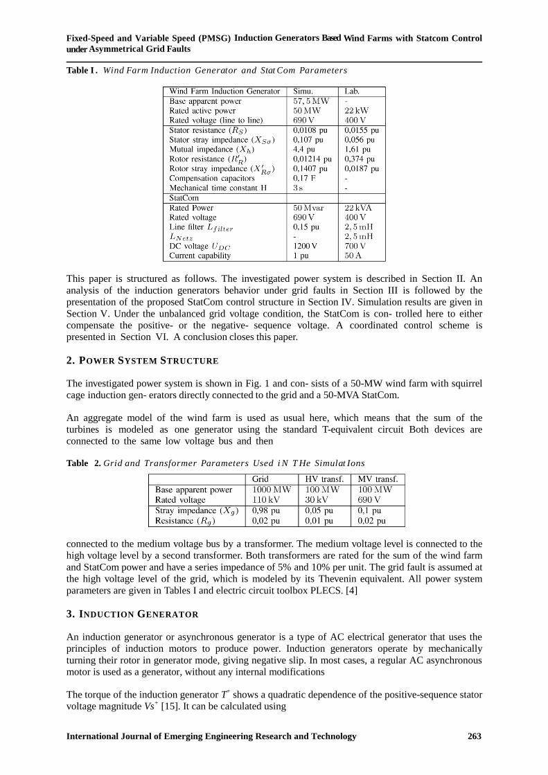
Table I . Wind Farm Induction Generator and Stat Com Parameters
This paper is structured as follows. The investigated power system is described in Section II. An
analysis of the induction generators behavior under grid faults in Section III is followed by the
presentation of the proposed StatCom control structure in Section IV. Simulation results are given in
Section V. Under the unbalanced grid voltage condition, the StatCom is con- trolled here to either
compensate the positive- or the negative- sequence voltage. A coordinated control scheme is
presented in Section VI. A conclusion closes this paper.
2. POWER SYSTEM STRUCTURE
The investigated power system is shown in Fig. 1 and con- sists of a 50-MW wind farm with squirrel
cage induction gen- erators directly connected to the grid and a 50-MVA StatCom.
An aggregate model of the wind farm is used as usual here, which means that the sum of the
turbines is modeled as one generator using the standard T-equivalent circuit Both devices are
connected to the same low voltage bus and then
Table 2. Grid and Transformer Parameters Used i N T He Simulat Ions
connected to the medium voltage bus by a transformer. The medium voltage level is connected to the
high voltage level by a second transformer. Both transformers are rated for the sum of the wind farm
and StatCom power and have a series impedance of 5% and 10% per unit. The grid fault is assumed at
the high voltage level of the grid, which is modeled by its Thevenin equivalent. All power system
parameters are given in Tables I and electric circuit toolbox PLECS. [4]
3. INDUCTION GENERATOR
An induction generator or asynchronous generator is a type of AC electrical generator that uses the
principles of induction motors to produce power. Induction generators operate by mechanically
turning their rotor in generator mode, giving negative slip. In most cases, a regular AC asynchronous
motor is used as a generator, without any internal modifications
The torque of the induction generator T+ shows a quadratic dependence of the positive-sequence stator
voltage magnitude Vs+ [15]. It can be calculated using
G.Pradeep Kumar Reddy & Smt S.D.S.Bhagyamma
International Journal of Emerging Engineering Research and Technology 264
where Rs, Rr, Xs, and Xr are the typical stator and rotor (subscripts s and r) resistance and impedance
parameters parameters of the machine equivalent circuit, p is the number of pole pairs, ωs is the
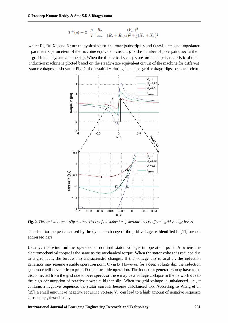
grid frequency, and s is the slip. When the theoretical steady-state torque–slip characteristic of the
induction machine is plotted based on the steady-state equivalent circuit of the machine for different
stator voltages as shown in Fig. 2, the instability during balanced grid voltage dips becomes clear.
Fig. 2. Theoretical torque–slip characteristics of the induction generator under different grid voltage levels.
Transient torque peaks caused by the dynamic change of the grid voltage as identified in [11] are not
addressed here.
Usually, the wind turbine operates at nominal stator voltage in operation point A where the
electromechanical torque is the same as the mechanical torque. When the stator voltage is reduced due
to a grid fault, the torque–slip characteristic changes. If the voltage dip is smaller, the induction
generator may resume a stable operation point C via B. However, for a deep voltage dip, the induction
generator will deviate from point D to an instable operation. The induction generators may have to be
disconnected from the grid due to over speed, or there may be a voltage collapse in the network due to
the high consumption of reactive power at higher slip. When the grid voltage is unbalanced, i.e., it
contains a negative sequence, the stator currents become unbalanced too. According to Wang et al.
[15], a small amount of negative sequence voltage Vs- can lead to a high amount of negative sequence
currents Is_ , described by
Fixed-Speed and Variable Speed (PMSG) Induction Generators Based Wind Farms with Statcom Control
under Asymmetrical Grid Faults
International Journal of Emerging Engineering Research and Technology 265
Where σ is the leakage factor, IS, N is the rated stator current, and Ls is the stator inductance. The
negative-sequence currents do not contribute a lot to the average torque T+; thus, they can still be
calculated using
But the negative-sequence currents cause torque oscillations of double grid frequency. The magnitude
of the negative-sequence torque T−
can be calculated using
It becomes clear that the average torque is reduced due to the decreased positive-sequence voltage.
Additionally, there are high torque oscillations of double grid frequency due to the negative-sequence
voltage. Thus, a reduction of the positive sequence stator voltage will lead to a reduction of the
average torque and an acceleration of the turbine. An existing negative sequence stator voltage will
cause torque oscillations, reducing the lifetime of the turbine drive train.
When the positive- and the negative-sequence voltage can be controlled independently by a StatCom,
the average torque and the torque ripple can also be controlled independently.
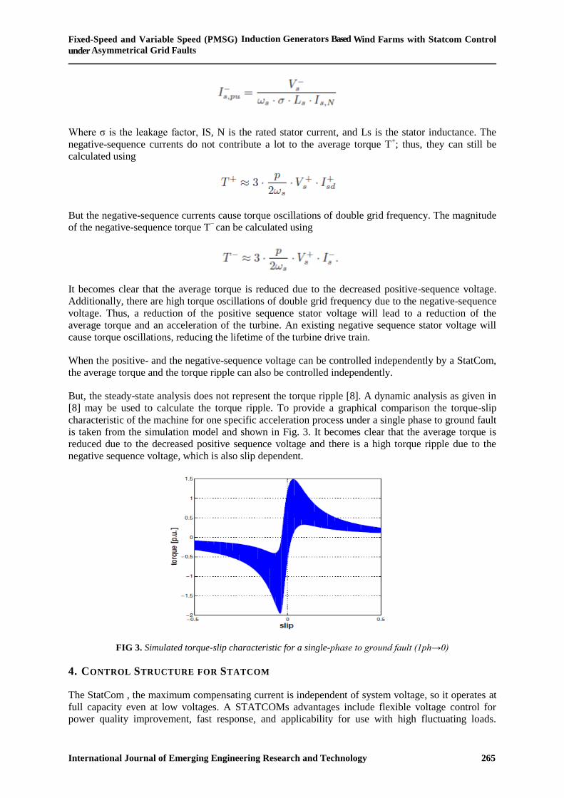
But, the steady-state analysis does not represent the torque ripple [8]. A dynamic analysis as given in
[8] may be used to calculate the torque ripple. To provide a graphical comparison the torque-slip
characteristic of the machine for one specific acceleration process under a single phase to ground fault
is taken from the simulation model and shown in Fig. 3. It becomes clear that the average torque is
reduced due to the decreased positive sequence voltage and there is a high torque ripple due to the
negative sequence voltage, which is also slip dependent.
FIG 3. Simulated torque-slip characteristic for a single-phase to ground fault (1ph→0)
4. CONTROL STRUCTURE FOR STATCOM
The StatCom , the maximum compensating current is independent of system voltage, so it operates at
full capacity even at low voltages. A STATCOMs advantages include flexible voltage control for
power quality improvement, fast response, and applicability for use with high fluctuating loads.

G.Pradeep Kumar Reddy & Smt S.D.S.Bhagyamma
International Journal of Emerging Engineering Research and Technology 266
Statcom control structure is based on the voltage oriented vector control scheme [16] as usually
applied to three-phase grid-connected converters.
It is a cascade control structure with inner proportional integral (PI) current controllers in a rotating dq
reference frame with grid voltage orientation. The PI controller transfer function is
The modeling and controller gain design of voltage-oriented controlled three-phase grid-connected
converters are described in [17]–[19].
Resonant controllers (Res) tuned at 100 Hz in the same Positive dq reference frame are added to
realize the negative sequence current control.
Note that the control of the negative-sequence currents can also be performed in a negative rotating
reference frame with PI controllers, but by using resonant controllers in a positive rotating reference
frame, there is no need for a sequence separation of the currents [30]. The overall control structure is
shown in Fig. 4.. Note that a possible StatCom converter topology is shown here as a two-level
voltage source converter connected to the grid by an LCL filter, while multilevel topologies will be
used for high-power applications.
The outer control loops are designed to control the dc voltage and the positive and negative sequences
of the voltage at the connection point of the StatCom. Therefore, a precise sequence separation of the
measured voltage into positive- and negative sequence components is necessary, which is performed
based on dual second-order generalized integrators [12]. Other sequence extraction methods could be
applied [19]. Using the sequence separation, the positive and the negative sequence of the voltage
appear as dc values and can be controlled by PI controllers. To ensure a safe operation of the StatCom
within its current capability, the current references given by the four outer controllers must be limited
to the maximum StatCom current. The priority is on the positive-sequence reactive current Iq+. Thus,
the StatCom ensures the maximum fault-ride-through enhancement of the wind farm by compensating
the positive sequence voltage. If there is a remaining StatCom current capability, the StatCom is
controlled to compensate the negative-sequence voltage additionally, in order to reduce the torque
ripple during the grid fault.
The positive- and negative-sequence current references are added. The negative-sequence current
references must be transformed into the positive rotating reference frame by a coordinate
transformation with twice the grid voltage angle. Note that the transient torques at the beginning and
end of the grid fault remain uncompensated using this control strategy.
For the investigations under unbalanced grid fault, different control targets will be compared to clarify
the effect of the positive- or the negative-sequence voltage compensation on the operation of the
induction generators. The target of the first method is to compensate the positive-sequence voltage,
while the negative-sequence voltage will remain unchanged. The target of the second method is to
eliminate the negative sequence of the voltage, while the positive sequence voltage will remain
unchanged.
5. RESULTS FOR UNBALANCED GRID FAULTS
An unbalanced fault (single phase amplitude drops to 60%) is assumed at the high voltage bus of the
power system (see Fig. 1). The simulation results are shown in below figures with simulation

Fixed-Speed and Variable Speed (PMSG) Induction Generators Based Wind Farms with Statcom Control
under Asymmetrical Grid Faults
International Journal of Emerging Engineering Research and Technology 267
diagrams. The unbalanced grid fault leads to a negative-sequence voltage at the medium voltage bus
[see Fig. 5].
The operation of the system without StatCom support is shown in the left part of Fig. 5. The
reduction of the positive- sequence voltage leads to a decrease in torque and an acceleration of the
rotor. The important differences compared to a balanced grid fault are the heavy torque
oscillations [see Fig. 7(c)] of the system caused by the negative-sequence voltage. For this simulation
case, the grid voltage fault does not lead to voltage instability because the generator can return to the
rated operation point after the fault.
In the middle of Fig. 7, the simulation results are shown for the same grid fault, but now, the system
is supported by the StatCom. In this case, the StatCom is controlled to compensate the positive
sequence of the voltage. Within the chosen current rating of the StatCom (here, 1 p.u.), the
positive-sequence voltage at the low voltage level can fully be compensated [see Fig. 7(b)] by
injecting a positive-sequence StatCom current [see Fig. 7 middle (e)]. Note that the current is purely
reactive, which cannot be seen from the figure, as only the magnitude of the positive- and negative-
sequence components is shown. The negative-sequence voltage component is not controlled and thus
remains unaffected. The compensation of the positive-sequence voltage guarantees the full torque
capability of the generator [see Fig. 7 middle (c)], and thus, the speed does not increase [see Fig. 7
middle (d)]. However, the presence of a negative- sequence voltage component leads to high torque
oscillations. In the right part of Fig. 7, the StatCom is controlled to eliminate the negative-sequence
component of the grid voltage. This is only possible by injecting a negative-sequence current into
the grid [see Fig. 7 right (e)]. The chosen strategy leads to a complete elimination of the negative-
sequence voltage at the StatCom voltage bus [see Fig. 7 right (b)], and thus, the heavy torque
oscillations during the unbalanced grid faults are elim- inated too. The positive-sequence voltage is
not compensated here, and thus, the generator accelerates [see Fig. 7 right (d)], leading to a
continuous decrease in the positive-sequence volt- age component [see Fig. 7 right (b)] due to the
reactive power consumption. However, the system does not reach the stability limit, and the generator
returns to nominal operation after the grid fault. Note that the drawback of the chosen StatCom
control strategy in this case might be the oscillating active and reactive powers of the StatCom
[see Fig. 7 right (f)]. In Fig. 5, the torque is plotted against the speed of the induction generator taken
from the same simulation results.
Now replacing the PMSG instead of asynchronous machine In FSIG simulation diagram for the
variable speed operation shown in fig 8. The simulation results for that shown in fig 9 by comparing
with the zero percent fault to the 60% fault percentage of asymmetrical grid faults. And the
controlling circuit shown in fig 6. In fig 8 Simulation results for operation during unbalanced grid
fault (1 ph → 60%) (left) without StatCom, (middle) with StatCom and positive-sequence voltage
compensation, and (right) with StatCom and negative-sequence voltage compensation. (a) Positive
and negative-sequence voltage components at PCC. (b) Positive- and negative-sequence voltage
components at low voltage. (c) StatCom positive and negative current components. (d) StatCom P, Q.
(e) Torque. (f) Speed.
The results of this section enhance the understanding of the voltage control performed by the
StatCom and the resulting operation of the induction generators. By compensating the positive-
sequence voltage, the torque capability of the induc- tion generators is increased, and an acceleration
during grid voltage dips can be decreased or avoided. By compensating the negative-sequence
voltage (the unbalanced component of the voltage), the torque oscillations of the induction generators
can be decreased or avoided. The capability of the StatCom to compensate a voltage component
depends on the chosen current rating of the StatCom and the impedance of the power system. For a
high current rating of the StatCom and a weak power sys- tem (with high system impedance), the
voltage compensation capability of the StatCom is also increased.

G.Pradeep Kumar Reddy & Smt S.D.S.Bhagyamma
International Journal of Emerging Engineering Research and Technology 268
Fig 4. Basic Diagram for Simulation
Fig. 4. Proposed control structure of the StatCom to control the positive- and the negative-sequence voltage
independentl
FIG 5: Simulation diagram of FSIG with Statcom

Fixed-Speed and Variable Speed (PMSG) Induction Generators Based Wind Farms with Statcom Control
under Asymmetrical Grid Faults
International Journal of Emerging Engineering Research and Technology 269
FIG 6: Design of control circuit
Simulation Results
Fig 7. FSIG with statcom control undrer asymmetrical grid faults
Fig 7: Simulation results for operation during unbalanced grid fault (1 ph → 60%) (left) without StatCom,
(middle) with StatCom and positive-sequence voltage compensation, and (right) with StatCom and negative-
sequence voltage compensation. (a) Positive and negative-sequence voltage components at PCC. (b) Positive-
and negative-sequence voltage components at low voltage. (c) StatCom positive and negative current
components. (d) StatCom P, Q. (e) Torque. (f) Speed.

G.Pradeep Kumar Reddy & Smt S.D.S.Bhagyamma
International Journal of Emerging Engineering Research and Technology 270
FIG 8: Placing PMSG instead of asynchronous machine of FSIG:
Fig 9: PMSG with statcom control undrer asymmetrical grid faults
Fig 9: Simulation results for operation during unbalanced grid fault (1 ph → 60%) (left) without StatCom,
(middle) with StatCom and positive-sequence voltage compensation, and (right) with StatCom and negative-
sequence voltage compensation. (a) Positive and negative-sequence voltage components at PCC. (b) Positive-
and negative-sequence voltage components at low voltage. (c) StatCom positive and negative current
components. (d) StatCom P, Q. (e) Torque. (f) Speed.
6. COORDINATED POSITIVE AND NEGATIVE -SEQUENCE VOLTAGE CONTROL AND
LIMITATIONS
Fixed-Speed and Variable Speed (PMSG) Induction Generators Based Wind Farms with Statcom Control
under Asymmetrical Grid Faults
International Journal of Emerging Engineering Research and Technology 271
In the previous section, either the positive-sequence volt- age or the negative-sequence voltage was
compensated by the StatCom. For smaller voltage dips, there might be a certain amount of unused
current capability of the StatCom. The current capability of the StatCom can be further exploited
if positive- and negative-sequence voltage components are compensated in coordination. A
prioritization of the positive sequence is proposed here in order to increase the voltage stability of the
wind farm. If the StatCom has remaining current capability, it is used for the negative-sequence voltage
compen- sation, leading to a reduction of torque ripple and increasing the lifetime of the generator drive
train.
Special focus is put on the maximum current capability of the StatCom that cannot be exceeded in
order to unbalanced-voltage dip (1 ph → 60%) when both the positive- and the negative-sequence
voltage components are compen sated are shown in Fig. 9 (left). The current capability of the
StatCom is sufficient to compensate both voltage components. For a more severe voltage dip (single
phase to ground at high voltage level) as shown in Fig. 9(right), the current capability of the
StatCom is no more sufficient to compensate both voltage components. Thus, the current limitation with
positive sequence priority ensures a maximum compensation of the positive- sequence voltage. The
drawback is obviously that there is no current capability left to compensate the negative-sequence
voltage, and therefore, the torque oscillations are present and stress the mechanical parts of the
generator.
7. CONCLUSION AND FUTURE WORK
In this project a wind turbine fed fixed speed induction generator is modeled under asymmetric grid
fault 1ph-50%.To mitigate these faults a static compensator is injected into the wind turbine fed fixed
speed induction generator. It also compensates the positive and negative sequence voltage and current.
The respective waveforms are verified for without and with static compensator. Similarly the same
procedure is evaluated 1ph-60% and 1ph-0% and the wind turbine characteristics have been worked
out.
Instead of fixed speed induction generator wind turbine fed doubly fed induction generator can be
evaluated under asymmetric grid faults. Instead of statcom, DVR (dynamic voltage restorer), Unified
power quality conditioner can used to attenuate the asymmetric faults in wind turbine fed FSIG and
DFIG as both DVR and UPQC have the fault mitigation capability. Instead of PI controller, hysteresis
controller can be employed and instantaneous theory; pq theory can be used in place of dq theory and
evaluated.
REFERENCES
[1] M. Molinas, J. Suul, and T. Undeland, “Extending the life of gear box in wind generators by
smoothing transient torque with STATCOM,” IEEE Trans. Ind. Electron., vol. 57, no. 2, pp.
476–484, Feb. 2010.
[2] S. Alepuz, S. Busquets-Monge, J. Bordonau, J. Martinez-Velasco, C. Silva, J. Pontt, and J.
Rodriguez, “Control strategies based on sym- metrical components for grid-connected converters
under voltage dips,” IEEE Trans. Ind. Electron., vol. 56, no. 6, pp. 2162–2173, Jun. 2009
[3] P. Rodriguez, A. Luna, G. Medeiros, R. Tedorescu, and F. Blaabjerg, “Control of statcom in
wind power plants based on induction generators during asymmetrical grid faults,” in Proc.
IPEC, Jun. 2010, pp. 2066–2073.
[4] M. Ali and B. Wu, “Comparison of stabilization methods for fixed speed wind generator
systems,” IEEE Trans. Power Del., vol. 25, no. 1, pp. 323–331, Jan. 2010.
[5] Y. Cheng, C. Qian, M. Crow, S. Pekarek, and S. Atcitty, “A comparison of diode-clamped and
cascaded multilevel converters for a statcom with energy storage,” IEEE Trans. Ind. Electron.,
vol. 53, no. 5, pp. 1512–1521, Oct. 2006.
[6] M. Slepchenkov, K. Smedley, and J. Wen, “Hexagram-converter-based statcom for voltage
support in fixed-speed wind turbine generation systems,” IEEE Trans. Ind. Electron., vol. 58,
no. 4, pp. 1120–1131, Apr. 2011

G.Pradeep Kumar Reddy & Smt S.D.S.Bhagyamma
International Journal of Emerging Engineering Research and Technology 272
[7] A. Ortiz, T. Ostrem, and W. Sulkowski, “Indirect negative sequence volt- age control for
STATCOM supporting wind farms directly connected to the grid,” in proc. IEEE 37th IECON,
Nov. 2011, pp. 1903–1908.
[8] D. Soto and T. Green, “A comparison of high-power converter topolo- gies for the
implementation of FACTS controllers,” IEEE Trans. Ind. Electron., vol. 49, no. 5, pp. 1072–
1080, Oct. 2002.
[9] J. Hu, Y. He, L. Xu, and B. Williams, “Improved control of DFIG systems during network
unbalance using PIR current regulators,” IEEE Trans. Ind. Electron., vol. 56, no. 2, pp. 439–451,
Feb. 2009.
[10] P. Rodriguez, R. Teodorescu, I. Candela, A. Timbus, M. Liserre, and F. Blaabjerg, “New
positive-sequence voltage detector for grid synchro- nization of power converters under faulty
grid conditions,” in Proc. 37th IEEE PESC, Jun. 2006, pp. 1–7.
[11] O. Anaya-Lara, N. Jenkins, J. Ekanayake, P. Cartwright, and M. Hughes, Wind Energy
Generation: Modelling and Control. Hoboken, NJ: Wiley, 2009.
[12] M. P. Kazmierkowski, R. Krishnan, F. Blaabjerg, and D. Irwin, Control in Power Electronics:
Selected Problems. New York: Academic, 2002, ser. Academic Press series in engineering
[13] B. Singh, S. Murthy, and S. Gupta, “Statcom-based voltage regulator for self-excited induction
generator feeding nonlinear loads,” IEEE Trans. Ind. Electron., vol. 53, no. 5, pp. 1437–1452,
Oct. 2006
[14] M. Liserre, R. Cardenas, M. Molinas, and J. Rodriguez, “Overview of multi-MW wind turbines
and wind parks,” IEEE Trans. Ind. Electron., vol. 58, no. 4, pp. 1081–1095, Apr. 2011.
[15] F. Van Hulle and N. Fichaux, “Powering Europe: Wind energy and the electricity grid,” Eur.
Wind Energy Assoc., Brussels, Belgium, Nov. 2010
[16] C. Wessels, R. Lohde, and F. W. Fuchs, “Transformer based voltage SAG generator to perform
LVRT and HVRT tests in the laboratory,” in Proc. 14th Int. EPE/PEMC, Sep. 2010, pp. T11-8–
T11-13.
[17] C. Hochgraf and R. Lasseter, “STATCOM controls for operation with unbalanced voltages,”
IEEE Trans. Power Del., vol. 13, no. 2, pp. 538–544, Apr. 1998.
[18] Gholami, A. Javanmard, B. “Necessity of design and production of reactive power compensation
in wind power plants”, (in Persian), 2009.
[19] A. Kehrli and M. Ross, “Understanding grid integration issues at wind farms and solutions using
voltage source converter FACTS technology,” in Proc. IEEE PES Gen. Meeting, Jul. 13–17,
2003, vol. 3, pp. 1822–1827.
[20] H. de Souza, F. Bradaschia, F. Neves, M. Cavalcanti, G. Azevedo, and J. de Arruda, “A method
for extracting the fundamental-frequency positive-sequence voltage vector based on simple
mathematical transformations,”IEEE Trans. Ind. Electron., vol. 56, no. 5, pp. 1539–1547, May
2009.