BLIND SPEECH SEPARATION OF MOVING SPEAKERS IN REAL REVERBERANT ENVIRONMENTS

HAL Id: hal-00811343https://hal.archives-ouvertes.fr/hal-00811343
Submitted on 23 Apr 2012
HAL is a multi-disciplinary open accessarchive for the deposit and dissemination of sci-entific research documents, whether they are pub-lished or not. The documents may come fromteaching and research institutions in France orabroad, or from public or private research centers.
L’archive ouverte pluridisciplinaire HAL, estdestinée au dépôt et à la diffusion de documentsscientifiques de niveau recherche, publiés ou non,émanant des établissements d’enseignement et derecherche français ou étrangers, des laboratoirespublics ou privés.
Fixed sound source localization in reverberantenvironments using a multi�microphone set
Hamid Meraoubi, Bachir Boudraa
To cite this version:Hamid Meraoubi, Bachir Boudraa. Fixed sound source localization in reverberant environments usinga multi�microphone set. Acoustics 2012, Apr 2012, Nantes, France. �hal-00811343�

Fixed sound source localization in reverberantenvironments using a multi-microphone set
H. Meraoubia and B. Boudraab
aCDTA, Cite 20 aout 1956 Baba Hassen, 16030 Algiers, AlgeriabUSTHB,Laboratoire de Communication Parlee etTraitement du Signal, B.P. 32, El-Alia,
Bab-Ezzouar, 16111 Alger, Algeria
Proceedings of the Acoustics 2012 Nantes Conference 23-27 April 2012, Nantes, France
3913

The aim of this study is the implementation of algorithms for locating fixed sound source using a set of 4
microphones, arranged in a linear geometry and whose inter-microphone distances are known. The first results
concern the duration of treatments to detect the arrival direction of the incident wave in reverberant
environments. In the series of tests conducted in this work, we keep constant both the sampling frequency
(Fe=44100Hz) as soon as the distance d between microphones. Then, we vary the angle of incidence of the
sound signal. The tests were repeated for different lengths of analysis windows. The tests were carried out in a
reverberant room and with a significant background noise. As the most applications are conducted in reverberant
rooms, the signals received by a sensor are the sum of those provided by both the direct and the reflected paths
through walls and other obstacles. In such a room, an exact detection of the sound source has been obtained by
considering only the beginning of the recordings corresponding to the 4 microphones. That needs a time analysis
widow comprised between 24ms (N=1024 samples) to 250 ms.
1 Introduction
The use of a series of microphones arranged in space
(commonly called microphone arrays) is the subject of
research in several areas. These include robotics,
navigation, seismic monitoring, localization of speakers
(teleconferencing), and hearing aids devices. Considering
the fact that the distance from each microphone to the
sound source is different, the sound emitted by the source
will arrive at the observation points at a slightly different
time. This lag time is used to deduce the direction of the
sound source.
Generally, three classes of source localization algorithms
are taken into account [1]. These methods can be classified
according to the techniques used and based on the:
i. Maximum output power steered beam former (SBF)
[2,3].
ii. High-resolution spectral estimation algorithm [4,5] .
iii. Time-delay estimation location technique [6,7,8] .
In the first category, the source is localized by
maximizing the output of a steerable beamformer. The
approach combines delay-and-sum beamforming with
statistical analysis to trace the position of the acoustic
source. The method is effective when the source is emitting
continuously but it may suffer when concurrent sound
sources are present. In the second category, beamforming-
based techniques are combined with high resolution
spectral analysis. The third category is based on estimating
the time difference (delay) between the incident wave and
the pairs of microphones. These delays are used to
determine the direction of the sound and are based
generally on the auto-correlation [9, 10,11]. Knapp and
Carter [12] proposed the generalized cross-correlation
(GCC) method that was the most popular technique for
TDOA (time delay of arrivals) estimation.
Other researchers [13, 14] proposed hybrid methods that
combine the three previous categories.
In this work, we use a method based on time-delay
estimation location technique. The aim of this study is the
implementation of algorithms for locating a fixed sound
source using a set of 4 microphones, arranged in a linear
geometry and whose inter-microphone distances are known.
This paper is organized as follows. In section 2, we
introduce the Cross-power Spectrum Phase (CSP) [11]
which does not require any a priori modeling of the noise
statistics and is particularly suitable for wide band signals
as speech. In section 3, we describe the experimental
application setup. Section 4 reports the results of our study
to illustrate algorithms performances in room acoustic
environments where reverberation, noise and interference
are commonly encountered. Conclusions close this paper in
Section 5.
2 Modified Cross-power Spectral
Phase (CSP)
Three categories of methods can be considered as an
estimation of the incident wave where delays can be used to
determine the direction of incidence [15].These methods
can be categorized by the techniques on which they are
based, namely:
Direction of incidence based on sound intensity;
Time-delay estimation from cross-power spectral
phase information;
Time-delay estimation based on cross-correlation
function analysis.
In the following, we use Time-delay estimation from
cross-power spectral phase information.
Consider a source S and an array consisting of N
receivers. For N=2, the original waveform s(t) emitted by a
source S impinges on the microphones 0 and 1 after having
been transformed by the convolution with the impulse
responses between the source and the sensors:
Where xi(t) is the microphone signal, hi(t) the impulse
response and ni(t) the additive noise sequence.
An ideal propagation model assumes that the signal
acquired by each sensor is a delayed ( ) and attenuated
( ) version of the original source signal. Mathematically,
the received signals are expressed as:
( ) ( ) (2)
: scaling factor
: Propagation delay between the source sound S and
the microphone i
( ) ( ) ( ) ( ) (1)
Proceedings of the Acoustics 2012 Nantes Conference23-27 April 2012, Nantes, France
3914

Figure 1: Simple sound field of one source and two
spatially separated microphones
The TDOA (Time Difference Of Arrival) is defined by
, considering microphone 1 as a reference ( Figure
1).
To estimate the delay between two microphones we usually
consider the maximum of the cross-correlation R12( ) defined by:
( ) ∫ ( )
( ) (3)
This cross-correlation gives the similarity between the two
signals x1(t) and x2(t). The cross-correlation function shows
a maximum in τ corresponding to the direction of the
incident wave. By considering the Fourier transforms X1(f)
and X2(f) of the signals x1(t) and x2(t) respectively, the
cross-correlation can be calculated by taking the inverse
Fourier transform of the cross spectral power density G12(f):
( ) ∫ ( )
(4)
Where
( ) ( ) ( ) (5)
This relationship is known as Wiener-Kinchine theorem.
The calculation of the Eq. (3) requires the integration of the
signal on an infinitely long-time. However an estimate of
the cross-correlation can be calculated on a finite time
window of length T.
The choice of the observation period is an important
parameter of the method. The optimal value is determined
the experimental conditions (signal to noise ratio,
reverberation) and CPU resources.
In the literature, a multiplicity of variants of generalized
cross-correlation has been presented [11]. They basically
introduce a weighting factor in order to take into account
the source signal and noise statistics in a Maximum
Likelihood scheme. The normalization factor is applied in
order to preserve only the phase information Eq. (6):
( ) ( ) ( )
‖ ( )‖ ‖ ( )‖
(6)
A version of this estimator was proposed by Rabinkin & al.
[16] as the Modified Cross-Power Spectrum Phase
(MCSP):
( ) ( ) ( )
(‖ ( )‖ ‖ ( )‖)
(7)
Where ρ can be determined using characteristics of the
noise and reverberations in a room. A good value of ρ can
be estimated experimentally for different enclosures in
normal rooms. If ρ=0, the algorithm becomes the un-
normalized cross correlation while ρ=1gives the cross
power spectral density as shown in the Eq. (6).
The appropriate value of ρ can be determined
experimentally according to the medium (ρ= 0.75 in a
regular medium and ρ= 0.8 in a reverberant environment).
This method is used to locate the source, but it is not robust
in the presence of disturbance (probability of a false
estimate for parts of the signal) [16]. Indeed, the presence
of noise and reverberation can produce false peaks in the
cross-correlation function. So, the analysis is performed by
windows, reducing the instability of a peak with the
hypothesis that the source does not change its position in a
time interval. Both reverberation and noise, accounted for
in the more realistic model in Eq. (1), contribute to increase
the variance of the delay estimates and can produce
spurious peaks in the CSP function. Consequently, a larger
analysis window helps in reducing the instability of the
correct peak, provided that the speaker does not change
his/her position within the considered time interval. This
observation suggests enhancing the estimation by averaging
the CSP over multiple frames. In frequency domain this
corresponds to an averaged cross-power spectrum:
( ) ∑ ( ) ( )
(‖ ( )‖ ‖ ( )‖)
(8)
This method reduces the computational complexity and the
effects of integration facilitate the estimate during a time
interval corresponding to the analysis window [16].
After estimating the delay between the signals of the two
microphones i and j, it is necessary to find the angle of the
incident wave of each microphone based on the geometry
of the arrangement of microphones. The far field
assumptions consider the distance L between the source and
the microphones much larger than the distance between two
microphones. Hence, the incident waves can be assumed as
parallel allowing simplified calculation [16].
A time delay, corresponding to the difference between the
arrival of the acoustic wave front at microphone M1 and
microphone M2 spaced by a distance d, is denoted as τ12
(Figure 12).
Figure 2: Acoustic wave front at microphones M1 and M2
Mic1 Mic2
S source
T1
T2
Proceedings of the Acoustics 2012 Nantes Conference 23-27 April 2012, Nantes, France
3915

Noting c the speed of sound in air, we can write:
( ) (9)
( )
(10)
We obtain a relation between the angle θ and the delay between the two signals. The knowledge of provides
access to the angular position of the source relative to the
axis of microphones.
3 Experimental section
In this work, we consider a source S and an array of 4
receivers. The experimental setup, which is outlined in
Figure 13, shows the block diagram of the application. The
implementation is performed in two parts. The first part
represents the acquisition which uses a series of four
identical omnidirectional microphones connected to their
respective sound cards (4 USB sound cards). Recording
files are used to estimate the direction of the angle of
incidence using algorithms implemented in Matlab. After
their acquisition to the desired sampling rate and after
applying a high pass filter at 200 Hz to eliminate
background noise, the signals are equalized.
The next step is the calculation of the FFT for each
analysis window in order to evaluate the MCSP. First, we
compute the product ( ) ( ) for each frame of the
signals considering microphones in pairs. Then, by dividing
the result by the product ( ‖ ( )‖ ‖ ( )‖), we obtain the
standard CSP, which allows keeping the phase information
[16]. According to this reference, the latter product
(denominator) is powered prior to ρ= 0.8 to eliminate
background noise. The maximum of CSP corresponds to
the time delay between the signals as observed in Figure 14.
By averaging the CSP over multiple frames according to
Eq. (8), we deduce the angle of incidence of the wave
according to Eq. (10). The block diagram of the application
steps is illustrated in Figure 15.
Figure 3: Block diagram of the implemented application
Figure 4: Time delay detection using MCSP algorithm
Figure 5: Angle estimation Algorithm using MCSP
Proceedings of the Acoustics 2012 Nantes Conference23-27 April 2012, Nantes, France
3916
4 Results and Evaluation
The objective of this study was the implementation of
algorithms for locating a fixed sound source using a set of 4
microphones, arranged in a given geometry and whose
inter-microphone distances are known.
The first problem was the simultaneous acquisition of
multiple signals. A solution has been proposed by the use of
multiple sound cards in helping us with Simulink (Matlab).
The second problem concerns highly reverberant
environments that make particularly difficult estimation of
the position of a reflecting barrier since a source signal can
be seen as an independent source.
Our work concerns the detection of the direction of
arrival of the incident wave (using general public
microphones) and the duration of treatment in reverberant
environments. To this end, the tests were carried out in a
very reverberant room and with a significant background
noise.
In this system, an array of four microphones classified
into two pairs is arranged in linear; the distance of two
adjacent microphones is d. They are placed in an empty
room of 6m x 3m x 4m, without obstacles. The sampling
frequency was Fe=44100Hz. In the series of tests
conducted, we kept constant the distance d between
microphones, while varying the angle of incidence of the
sound source signal. These tests were repeated for different
lengths of analysis windows.
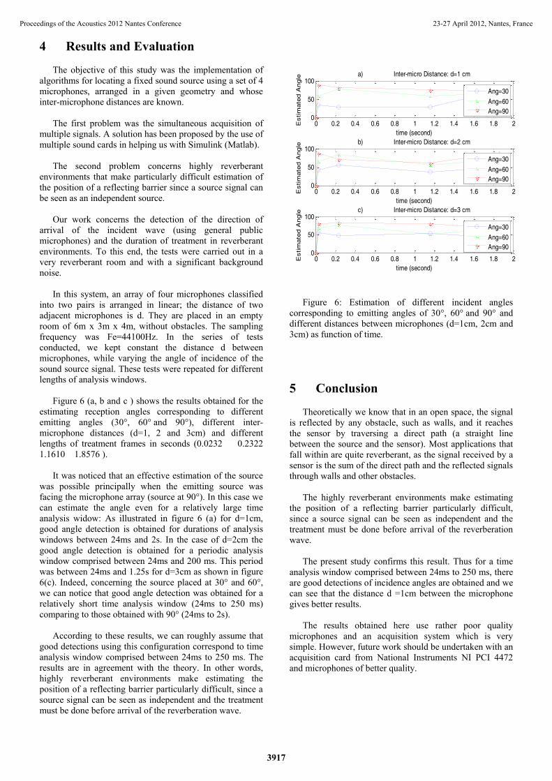
Figure 6 (a, b and c ) shows the results obtained for the
estimating reception angles corresponding to different
emitting angles (30°, 60° and 90°), different inter-
microphone distances (d=1, 2 and 3cm) and different
lengths of treatment frames in seconds (0.0232 0.2322
1.1610 1.8576 ).
It was noticed that an effective estimation of the source
was possible principally when the emitting source was
facing the microphone array (source at 90°). In this case we
can estimate the angle even for a relatively large time
analysis widow: As illustrated in figure 6 (a) for d=1cm,
good angle detection is obtained for durations of analysis
windows between 24ms and 2s. In the case of d=2cm the
good angle detection is obtained for a periodic analysis
window comprised between 24ms and 200 ms. This period
was between 24ms and 1.25s for d=3cm as shown in figure
6(c). Indeed, concerning the source placed at 30° and 60°,
we can notice that good angle detection was obtained for a
relatively short time analysis window (24ms to 250 ms)
comparing to those obtained with 90° (24ms to 2s).
According to these results, we can roughly assume that
good detections using this configuration correspond to time
analysis window comprised between 24ms to 250 ms. The
results are in agreement with the theory. In other words,
highly reverberant environments make estimating the
position of a reflecting barrier particularly difficult, since a
source signal can be seen as independent and the treatment
must be done before arrival of the reverberation wave.
Figure 6: Estimation of different incident angles
corresponding to emitting angles of 30°, 60° and 90° and
different distances between microphones (d=1cm, 2cm and
3cm) as function of time.
5 Conclusion
Theoretically we know that in an open space, the signal
is reflected by any obstacle, such as walls, and it reaches
the sensor by traversing a direct path (a straight line
between the source and the sensor). Most applications that
fall within are quite reverberant, as the signal received by a
sensor is the sum of the direct path and the reflected signals
through walls and other obstacles.
The highly reverberant environments make estimating
the position of a reflecting barrier particularly difficult,
since a source signal can be seen as independent and the
treatment must be done before arrival of the reverberation
wave.
The present study confirms this result. Thus for a time
analysis window comprised between 24ms to 250 ms, there
are good detections of incidence angles are obtained and we
can see that the distance d =1cm between the microphone
gives better results.
The results obtained here use rather poor quality
microphones and an acquisition system which is very
simple. However, future work should be undertaken with an
acquisition card from National Instruments NI PCI 4472
and microphones of better quality.
0 0.2 0.4 0.6 0.8 1 1.2 1.4 1.6 1.8 20
50
100a) Inter-micro Distance: d=1 cm
time (second)
Estim
ate
d A
ngle
0 0.2 0.4 0.6 0.8 1 1.2 1.4 1.6 1.8 20
50
100b) Inter-micro Distance: d=2 cm
time (second)
Estim
ate
d A
ngle
0 0.2 0.4 0.6 0.8 1 1.2 1.4 1.6 1.8 20
50
100c) Inter-micro Distance: d=3 cm
time (second)
Estim
ate
d A
ngle
Ang=30
Ang=60
Ang=90
Ang=30
Ang=60
Ang=90
Ang=30
Ang=60
Ang=90
Proceedings of the Acoustics 2012 Nantes Conference 23-27 April 2012, Nantes, France
3917

References
[1] M. Brandstein, “A frame work for speech source
localisation using sensor arrays,” Doctoral dissertation
university, May 1995.
[2] Elko GW. Chou TC, “A constant directivity
beamforming microphone array,” Lustberg RJ and
Goodwin MM 1994.
[3] Ikeda A. Miz Oguchi H, Sasaki Y, E Nomoto T and
Kagami, “ 2D sound source localization in azimuth and
elevation from microphone array by using a directional
pattern of element ,” IEEE sensors 2007.
[4] Jin S, Kim HS, Lee CH, Choi J S and Jeon JW, “Real
time sound source localization system based on
FPGA,” Poc 6th IEEE Int. Conf. Ind. Inform, 2008.
[5] S. Bourennane and A. Bendjama. “Locating wide band
acoustic sources using higher order statistics,” Applied
Acoustics, pp. 235-251, April 2002.
[6] Kwon B. Park Y and Park Y-S,“Sound source
localization using the compensation method in robot
platform Proc,” IEEE Int. Conf. Control autom. Syst,
2007.
[7] Jin S, Kim HS, Lee CH, Choi J S and Jeon JW, “Real
time sound source localization system based on
FPGA,” Poc 6th IEEE Int. Conf. Ind. Inform, 2008.
[8] Kobayashi T, Kameda Y and Ohta Y,“Sound source
localization with non calibrated microphone,” Adv.
Multimedia model, 2008.
[9] Atmoko H,Tam D C, Tian G Y and Fazenda B,
“Accurate sound source localization in a reverberant
environment using multiple acoustic sensors. Meas”.
Sci. Technol, 2008.
[10] Brutti A, Omologo M and Svaizer P, “Comparison
between different sound source localization techniques
based on a real data collection”, Proc. Hands-Free
speech commun. Microphone Arrays, 2008.
[11] Hu J-S, Yang C-H and Wang C-K, “Sound source
localization by microphone array on a mobile robot
using eigen-structure based generalizerd cross
correlation”, IEEE ARSO, 2008.
[12] C. Knapp and G. Carter,“The generalized correlation
method for estimation of time delay”. IEEE
Transactions on acoustic speech and signal processing,
august 1976.
[13] Ikeda A. Miz Oguchi H, Sasaki Y, E Nomoto T and
Kagami, “ 2D sound source localization in azimuth and
elevation from microphone array by using a directional
pattern of element”, IEEE sensors 2007.
[14] Kim H-D, Komatani K, Ogata T and Okuno HG, “
Design and evaluation of two channel based sound
source localization over entire azimuth range for
moving talkers”, IEEE/RSI Int. Conf. Intell. Robots
syst, 2008.
[15] Brent C. Kirkwood, “ Acoustic Source Localization
Using Time-Delay Estimation ”, Technical University
of Denmark, August 4, 2003.
[16] D. V. Rabinkin, R. J. Renomeron, A. Dahl, J. C.
French, and J. L. Flanagan, “A DSP implementation of
source location using microphone arrays,” in
Proceedings of the 131st Meeting of the Acoustical
Society of America, pp. 88–99, Indianapolis, Ind,
USA, 1996.
Proceedings of the Acoustics 2012 Nantes Conference23-27 April 2012, Nantes, France
3918