Fixed firefighting systems — Gas extinguishing...
106
BRITISH STANDARD BS EN 15004-1:2008 Fixed firefighting systems — Gas extinguishing systems — Part 1: Design, installation and maintenance ICS 13.220.20 Bought by Mr Paul Ray, Compco Fire Systems. Latest version as of 25/09/2009 14:21. Not to be distributed/networked. For multi-user access go to www.bsigroup.com/license © British Standards Institution
Transcript of Fixed firefighting systems — Gas extinguishing...

Bou
ght b
y M
r P
aul R
ay, C
ompc
o F
ire S
yste
ms.
Lat
est v
ersi
on a
s of
25/
09/2
009
14:2
1. N
ot to
be
dist
ribut
ed/n
etw
orke
d. F
or m
ulti-
user
acc
ess
go to
ww
w.b
sigr
oup.
com
/lice
nse
© B
ritis
h S
tand
ards
Inst
itutio
n
BRITISH STANDARD
BS EN 15004-1:2008Fixed firefighting systems — Gas extinguishing systems —Part 1: Design, installation and maintenance
ICS 13.220.20

BS EN 15004-1:2008
Bou
ght b
y M
r P
aul R
ay, C
ompc
o F
ire S
yste
ms.
Lat
est v
ersi
on a
s of
25/
09/2
009
14:2
1. N
ot to
be
dist
ribut
ed/n
etw
orke
d. F
or m
ulti-
user
acc
ess
go to
ww
w.b
sigr
oup.
com
/lice
nse
© B
ritis
h S
tand
ards
Inst
itutio
n
This British Standard was published under the authority of the Standards Policy and Strategy Committee on 30 Novemer 2008
© BSI 2008
ISBN 978 0 580 54500 9
National foreword
This British Standard is the UK implementation of EN 15004-1:2008. It supersedes BS ISO 14520-1:2006 which is withdrawn.The UK participation in its preparation was entrusted by Technical Committee FSH/18, Fixed firefighting systems, to Subcommittee FSH/18/6, Gaseous extinguishing media and systems.A list of organizations represented on this committee can be obtained on request to its secretary.This publication does not purport to include all the necessary provisions of a contract. Users are responsible for its correct application.Compliance with a British Standard cannot confer immunity from legal obligations.
Amendments/corrigenda issued since publication
Date Comments

EUROPEAN STANDARD
NORME EUROPÉENNE
EUROPÄISCHE NORM
EN 15004-1
June 2008
ICS 13.220.20
English Version
Fixed firefighting systems - Gas extinguishing systems - Part 1:Design, installation and maintenance (ISO 14520-1:2006,
modified)
Installations fixes de lutte contre l'incendie - Installationsd'extinction à gaz - Partie 1 : Calcul, installation et
maintenance (ISO 14520-1:2006, modifiée)
Ortsfeste Brandbekämpfungsanlagen - Löschanlagen mitgasförmigen Löschmitteln - Teil 1: Planung, Installation und
Instandhaltung (ISO 14520-1:2006, modifiziert)
This European Standard was approved by CEN on 26 April 2008.
CEN members are bound to comply with the CEN/CENELEC Internal Regulations which stipulate the conditions for giving this EuropeanStandard the status of a national standard without any alteration. Up-to-date lists and bibliographical references concerning such nationalstandards may be obtained on application to the CEN Management Centre or to any CEN member.
This European Standard exists in three official versions (English, French, German). A version in any other language made by translationunder the responsibility of a CEN member into its own language and notified to the CEN Management Centre has the same status as theofficial versions.
CEN members are the national standards bodies of Austria, Belgium, Bulgaria, Cyprus, Czech Republic, Denmark, Estonia, Finland,France, Germany, Greece, Hungary, Iceland, Ireland, Italy, Latvia, Lithuania, Luxembourg, Malta, Netherlands, Norway, Poland, Portugal,Romania, Slovakia, Slovenia, Spain, Sweden, Switzerland and United Kingdom.
EUROPEAN COMMITTEE FOR STANDARDIZATIONC O M I T É E U R O P É E N D E N O R M A LI S A T I O NEUR OP ÄIS C HES KOM ITEE FÜR NOR M UNG
Management Centre: rue de Stassart, 36 B-1050 Brussels
© 2008 CEN All rights of exploitation in any form and by any means reservedworldwide for CEN national Members.
Ref. No. EN 15004-1:2008: E
Bou
ght b
y M
r P
aul R
ay, C
ompc
o F
ire S
yste
ms.
Lat
est v
ersi
on a
s of
25/
09/2
009
14:2
1. N
ot to
be
dist
ribut
ed/n
etw
orke
d. F
or m
ulti-
user
acc
ess
go to
ww
w.b
sigr
oup.
com
/lice
nse
© B
ritis
h S
tand
ards
Inst
itutio
n

EN 15004-1:2008 (E)
2
Contents Page
Foreword..............................................................................................................................................................6 Introduction .........................................................................................................................................................9 1 Scope ....................................................................................................................................................11 2 Normative references ..........................................................................................................................11 3 Terms and definitions .........................................................................................................................13 4 Use and limitations..............................................................................................................................16 4.1 General..................................................................................................................................................16 4.2 Extinguishants .....................................................................................................................................16 4.3 Electrostatic discharge .......................................................................................................................17 4.4 Compatibility with other extinguishants ...........................................................................................17 4.5 Temperature limitations ......................................................................................................................17 5 Safety ....................................................................................................................................................17 5.1 Hazard to personnel ............................................................................................................................17 5.2 Safety precautions...............................................................................................................................18 5.2.1 General..................................................................................................................................................18 5.2.2 For normally unoccupied areas .........................................................................................................18 5.2.3 For unoccupiable areas ......................................................................................................................19 5.3 Occupiable areas .................................................................................................................................19 5.4 Electrical hazards ................................................................................................................................20 5.5 Electrical earthing................................................................................................................................20 5.6 Electrostatic discharge .......................................................................................................................20 6 System design......................................................................................................................................20 6.1 General..................................................................................................................................................20 6.2 Extinguishant supply ..........................................................................................................................21 6.2.1 Quantity ................................................................................................................................................21 6.2.2 Quality...................................................................................................................................................21 6.2.3 Container arrangement .......................................................................................................................21 6.2.4 Storage containers ..............................................................................................................................21 6.3 Distribution...........................................................................................................................................22 6.3.1 General..................................................................................................................................................22 6.3.2 Piping ....................................................................................................................................................23 6.3.3 Fittings ..................................................................................................................................................23 6.3.4 Pipe and valve supports .....................................................................................................................24 6.3.5 Valves....................................................................................................................................................25 6.3.6 Nozzles..................................................................................................................................................25 6.3.7 Pressure reducing orifice assembly..................................................................................................26 6.4 Detection, actuation and control systems ........................................................................................26 6.4.1 General..................................................................................................................................................26 6.4.2 Automatic detection ............................................................................................................................26 6.4.3 Operating devices................................................................................................................................27 6.4.4 Control equipment ...............................................................................................................................27
BS EN 15004-1:2008B
ough
t by
Mr
Pau
l Ray
, Com
pco
Fire
Sys
tem
s. L
ates
t ver
sion
as
of 2
5/09
/200
9 14
:21.
Not
to b
e di
strib
uted
/net
wor
ked.
For
mul
ti-us
er a
cces
s go
tow
ww
.bsi
grou
p.co
m/li
cens
e ©
Brit
ish
Sta
ndar
ds In
stitu
tion

EN 15004-1:2008 (E)
3
6.4.5 Operating alarms and indicators .......................................................................................................28 6.4.6 Stop devices ........................................................................................................................................28 7 Extinguishant .......................................................................................................................................28 7.1 General .................................................................................................................................................28 7.2 Specifications, plans and approvals .................................................................................................28 7.2.1 Specifications ......................................................................................................................................28 7.2.2 Working documents ............................................................................................................................28 7.3 System flow calculations....................................................................................................................29 7.3.1 General .................................................................................................................................................29 7.3.2 Balanced and unbalanced system.....................................................................................................29 7.3.3 Friction losses .....................................................................................................................................29 7.3.4 Pressure drop ......................................................................................................................................29 7.3.5 Valves and fittings...............................................................................................................................29 7.3.6 Piping length........................................................................................................................................30 7.3.7 Drawings...............................................................................................................................................30 7.3.8 Liquefied gases – Specific requirements..........................................................................................30 7.4 Enclosures ...........................................................................................................................................31 7.5 Extinguishant concentration requirements ......................................................................................32 7.5.1 Flame extinguishment.........................................................................................................................32 7.6 Total flooding quantity........................................................................................................................33 7.6.1 General .................................................................................................................................................33 7.6.2 Liquefied gases ...................................................................................................................................33 7.6.3 Non-liquefied gas ................................................................................................................................34 7.7 Altitude adjustment .............................................................................................................................34 7.8 Duration of protection.........................................................................................................................35 7.9 System performance ...........................................................................................................................35 7.9.1 Discharge time.....................................................................................................................................35 7.9.2 Extended discharge ............................................................................................................................36 8 Commissioning and acceptance .......................................................................................................36 8.1 General .................................................................................................................................................36 8.2 Tests .....................................................................................................................................................36 8.2.1 General .................................................................................................................................................36 8.2.2 Enclosure check ..................................................................................................................................36 8.2.3 Review of mechanical components...................................................................................................36 8.2.4 Review of enclosure integrity ............................................................................................................37 8.2.5 Review of electrical components.......................................................................................................37 8.2.6 Preliminary functional tests ...............................................................................................................38 8.2.7 System functional operational test....................................................................................................39 8.2.8 Remote monitoring operations (if applicable)..................................................................................39 8.2.9 Control panel primary power source.................................................................................................39 8.2.10 Completion of functional tests...........................................................................................................39 8.3 Completion certificate and documentation ......................................................................................39 9 Inspection, maintenance, testing and training.................................................................................40 9.1 General .................................................................................................................................................40 9.2 Inspection.............................................................................................................................................40 9.2.1 General .................................................................................................................................................40 9.2.2 Container ..............................................................................................................................................40 9.2.3 Hose ......................................................................................................................................................40 9.2.4 Enclosures ...........................................................................................................................................41 9.3 Maintenance.........................................................................................................................................41
BS EN 15004-1:2008B
ough
t by
Mr
Pau
l Ray
, Com
pco
Fire
Sys
tem
s. L
ates
t ver
sion
as
of 2
5/09
/200
9 14
:21.
Not
to b
e di
strib
uted
/net
wor
ked.
For
mul
ti-us
er a
cces
s go
tow
ww
.bsi
grou
p.co
m/li
cens
e ©
Brit
ish
Sta
ndar
ds In
stitu
tion

EN 15004-1:2008 (E)
4
9.3.1 General..................................................................................................................................................41 9.3.2 User's programme of inspection........................................................................................................41 9.3.3 Service schedule..................................................................................................................................41 9.4 Training.................................................................................................................................................42 Annex A (normative) Working documents .....................................................................................................43 A.1 General..................................................................................................................................................43 A.2 Working documents ............................................................................................................................43 A.3 Specific details.....................................................................................................................................44 A.3.1 Pre-engineered systems .....................................................................................................................44 A.3.2 Engineered systems............................................................................................................................44 Annex B (normative) Determination of flame-extinguishing concentration of gaseous
extinguishants by the cup burner method........................................................................................45 B.1 General..................................................................................................................................................45 B.2 Principle................................................................................................................................................45 B.3 Requirements for apparatus...............................................................................................................45 B.3.1 General..................................................................................................................................................45 B.3.2 Cup ........................................................................................................................................................46 B.3.3 Chimney................................................................................................................................................46 B.3.4 Diffuser .................................................................................................................................................47 B.3.5 Fuel supply ...........................................................................................................................................47 B.3.6 Manifold ................................................................................................................................................47 B.3.7 Air supply .............................................................................................................................................47 B.3.8 Extinguishant supply ..........................................................................................................................47 B.3.9 Delivery system....................................................................................................................................47 B.4 Requirements for materials ................................................................................................................47 B.4.1 Air ..........................................................................................................................................................47 B.4.2 Fuel........................................................................................................................................................47 B.4.3 Extinguishant .......................................................................................................................................47 B.5 Procedure for flammable liquids........................................................................................................48 B.6 Procedure for flammable gases .........................................................................................................48 B.7 Extinguishant extinguishing concentration......................................................................................49 B.7.1 Preferred method.................................................................................................................................49 B.7.2 Alternative method ..............................................................................................................................49 B.8 Reporting of results.............................................................................................................................50 Annex C (normative) Fire extinguishment/area coverage fire test procedure for engineered and
pre-engineered extinguishing units...................................................................................................51 C.1 Requirements .......................................................................................................................................51 C.2 Type of test...........................................................................................................................................51 C.3 Extinguishing system..........................................................................................................................52 C.4 Extinguishing concentration ..............................................................................................................53 C.5 Nozzle distribution verification tests .................................................................................................53 C.5.1 Nozzles minimum height/maximum area coverage test ..................................................................53 C.5.2 Nozzles maximum height test ............................................................................................................58 C.6 Extinguishing concentration tests.....................................................................................................59 C.6.1 Wood crib test ......................................................................................................................................59 C.6.2 Heptane pan test ..................................................................................................................................64 C.6.3 Polymeric sheet fire test .....................................................................................................................65 Annex D (normative) Method of evaluating inerting concentration of a fire extinguishant ......................71 D.1 General..................................................................................................................................................71 D.2 Principle................................................................................................................................................71 D.3 Apparatus .............................................................................................................................................71 D.4 Procedure .............................................................................................................................................71 D.5 Inerting concentration.........................................................................................................................72 Annex E (normative) Door fan test for determination of minimum hold time.............................................73 E.1 General..................................................................................................................................................73 E.2 Test for determination of predicted hold time ..................................................................................73
BS EN 15004-1:2008B
ough
t by
Mr
Pau
l Ray
, Com
pco
Fire
Sys
tem
s. L
ates
t ver
sion
as
of 2
5/09
/200
9 14
:21.
Not
to b
e di
strib
uted
/net
wor
ked.
For
mul
ti-us
er a
cces
s go
tow
ww
.bsi
grou
p.co
m/li
cens
e ©
Brit
ish
Sta
ndar
ds In
stitu
tion

EN 15004-1:2008 (E)
5
E.2.1 Principle................................................................................................................................................73 E.2.2 Apparatus.............................................................................................................................................74 E.2.3 Calibration and accuracy of apparatus .............................................................................................74 E.2.4 Preliminary preparation ......................................................................................................................74 E.2.5 Evaluation of enclosure ......................................................................................................................75 E.2.6 Measurement of enclosure.................................................................................................................75 E.2.7 Test procedure.....................................................................................................................................76 E.2.8 Calculation ...........................................................................................................................................79 E.3 Treatment of enclosures with predicted hold times less than the recommended value.............87 E.3.1 General .................................................................................................................................................87 E.3.2 Leakage areas......................................................................................................................................87 E.3.3 Improved sealing of the enclosure ....................................................................................................87 E.3.4 Quantification and location of leaks..................................................................................................87 E.4 Report ...................................................................................................................................................88 Annex F (informative) System performance verification ..............................................................................90 Annex G (informative) Safe personnel exposure guidelines........................................................................91 G.1 General .................................................................................................................................................91 G.2 Safety ....................................................................................................................................................91 G.3 Hazards to Personnel..........................................................................................................................91 G.3.1 Agent itself ...........................................................................................................................................91 G.3.2 Noise .....................................................................................................................................................91 G.3.3 Turbulence ...........................................................................................................................................91 G.3.4 Low temperature..................................................................................................................................91 G.4 Halocarbon agents ..............................................................................................................................92 G.4.1 Toxicity of halocarbons (liquefied gases).........................................................................................92 G.4.2 PBPK Model .........................................................................................................................................93 G.4.3 Safe exposure guidelines for halocarbons.......................................................................................94 G.5 Inert Gas (non-liquefied gas)..............................................................................................................96 G.5.1 Physiological effects of inert gas agents..........................................................................................96 G.5.2 Safe exposure guidelines for inert gas agents ................................................................................96 Annex H (informative) Flow calculation implementation method and flow calculation verification
and testing for approvals....................................................................................................................98 H.1 General .................................................................................................................................................98 H.2 Calculation method implementation .................................................................................................98 H.3 Minimum accuracy recommendations ..............................................................................................99 H.3.1 Physical quantities ..............................................................................................................................99 H.3.2 Recommended design limits to be included inside the flow calculation method (software)......99 H.4 Recommended testing procedure for system flow calculation method (software)
validation..............................................................................................................................................99 H.4.1 General .................................................................................................................................................99 H.4.2 System design for testing.................................................................................................................100 H.5 Pass/fail criteria .................................................................................................................................101 Bibliography....................................................................................................................................................102
BS EN 15004-1:2008B
ough
t by
Mr
Pau
l Ray
, Com
pco
Fire
Sys
tem
s. L
ates
t ver
sion
as
of 2
5/09
/200
9 14
:21.
Not
to b
e di
strib
uted
/net
wor
ked.
For
mul
ti-us
er a
cces
s go
tow
ww
.bsi
grou
p.co
m/li
cens
e ©
Brit
ish
Sta
ndar
ds In
stitu
tion

EN 15004-1:2008 (E)
6
Foreword
This document (EN 15004-1:2008) has been prepared by Technical Committee CEN/TC 191 “Fixed firefighting systems”, the secretariat of which is held by BSI.
This European Standard shall be given the status of a national standard, either by publication of an identical text or by endorsement, at the latest by December 2008, and conflicting national standards shall be withdrawn at the latest by December 2008.
Attention is drawn to the possibility that some of the elements of this document may be the subject of patent rights. CEN [and/or CENELEC] shall not be held responsible for identifying any or all such patent rights.
According to the CEN/CENELEC Internal Regulations, the national standards organizations of the following countries are bound to implement this European Standard: Austria, Belgium, Bulgaria, Cyprus, Czech Republic, Denmark, Estonia, Finland, France, Germany, Greece, Hungary, Iceland, Ireland, Italy, Latvia, Lithuania, Luxembourg, Malta, Netherlands, Norway, Poland, Portugal, Romania, Slovakia, Slovenia, Spain, Sweden, Switzerland and the United Kingdom.
The text of the International Standard ISO 14520-1:2006 from Technical Committee ISO/TC 21 "Equipment for fire protection and fire fighting" of the International Organization for Standardization (ISO) has been taken over as a European Standard by Technical Committee CEN/TC 191 "Fixed firefighting systems", the secretariat of which is held by BSI, with common modifications which are indicated by a straight line in the margin of the text. Where the text in ISO 14520-1 gives the reference to "ISO 14520-1" or "this part of ISO 14520" this document refers only to "this document" and is not marked by a straight line.
This European Standard will consist of the following parts, under the general title "Fixed firefighting systems – Gas extinguishing systems":
Part 1: Design, installation and maintenance (ISO 14520-1, modified)
Part 2: Physical properties and system design of gas extinguishing systems for FK-5-1-12 extinguishant (ISO 14520-5, modified)
Part 3: Physical properties and system design of gas extinguishing systems for HCFC Blend A extinguishant (ISO 14520-6, modified)
Part 4: Physical properties and system design of gas extinguishing systems for HFC 125 extinguishant (ISO 14520-8, modified)
Part 5: Physical properties and system design of gas extinguishing systems for HFC 227ea extinguishant (ISO 14520-9, modified)
Part 6: Physical properties and system design of gas extinguishing systems for HFC 23 extinguishant (ISO 14520-10, modified)
Part 7: Physical properties and system design of gas extinguishing systems for IG-01 extinguishant (ISO 14520-12, modified)
Part 8: Physical properties and system design of gas extinguishing systems for IG-100 extinguishant (ISO 14520-13, modified)
Part 9: Physical properties and system design of gas extinguishing systems for IG-55 extinguishant (ISO 14520-14, modified)
BS EN 15004-1:2008B
ough
t by
Mr
Pau
l Ray
, Com
pco
Fire
Sys
tem
s. L
ates
t ver
sion
as
of 2
5/09
/200
9 14
:21.
Not
to b
e di
strib
uted
/net
wor
ked.
For
mul
ti-us
er a
cces
s go
tow
ww
.bsi
grou
p.co
m/li
cens
e ©
Brit
ish
Sta
ndar
ds In
stitu
tion

EN 15004-1:2008 (E)
7
Part 10: Physical properties and system design of gas extinguishing systems for IG-541 extinguishant (ISO 14520-15, modified)
ISO 14520-1:2006 has the following foreword:
ISO (the International Organization for Standardization) is a worldwide federation of national standards bodies (ISO member bodies). The work of preparing International Standards is normally carried out through ISO technical committees. Each member body interested in a subject for which a technical committee has been established has the right to be represented on that committee. International organizations, governmental and non-governmental, in liaison with ISO, also take part in the work. ISO collaborates closely with the International Electrotechnical Commission (IEC) on all matters of electrotechnical standardization.
International Standards are drafted in accordance with the rules given in the ISO/IEC Directives, Part 2.
The main task of technical committees is to prepare International Standards. Draft International Standards adopted by the technical committees are circulated to the member bodies for voting. Publication as an International Standard requires approval by at least 75 % of the member bodies casting a vote.
Attention is drawn to the possibility that some of the elements of this document may be the subject of patent rights. ISO shall not be held responsible for identifying any or all such patent rights.
ISO 14520-1 was prepared by Technical Committee ISO/TC 21, Equipment for fire protection and fire fighting, Subcommittee SC 8, Gaseous media and firefighting systems using gas.
This second edition cancels and replaces the first edition (ISO 14620-1:2000), which has been technically revised.
Annex C has been extensively revised to include polymeric sheet fuel array fire tests [polymethyl methacrylate (PMMA)], [polypropylene (PP)] and [acrylonitrile-butadiene-styrene (ABS)]. These tests are designed to more closely represent plastic fuel hazards such as may be encountered in information technology, telecommunications and process control facilities.
Annex E has been re-structured to accommodate lighter-than-air gases and to provide means for dealing with non-standard (as opposed to geometrically regular) hazard enclosures.
Also incorporated in this revision of ISO 14520-1 are safe personnel exposure guidelines, Annex G, recognizing physiologically based pharmacokinetic (PBPK) modelling and hypoxic guidelines to define safe human exposure limits.
ISO 14520 consists of the following parts, under the general title Gaseous media fire extinguishing systems — Physical properties and system design:
Part 1: General requirements
Part 2: CF3I extinguishant
Part 5: FK-5-1-12 extinguishant
Part 6: HCFC Blend A extinguishant
Part 8: HFC 125 extinguishant
Part 9: HFC 227ea extinguishant
Part 10: HFC 23 extinguishant
BS EN 15004-1:2008B
ough
t by
Mr
Pau
l Ray
, Com
pco
Fire
Sys
tem
s. L
ates
t ver
sion
as
of 2
5/09
/200
9 14
:21.
Not
to b
e di
strib
uted
/net
wor
ked.
For
mul
ti-us
er a
cces
s go
tow
ww
.bsi
grou
p.co
m/li
cens
e ©
Brit
ish
Sta
ndar
ds In
stitu
tion

EN 15004-1:2008 (E)
8
Part 11: HFC 236fa extinguishant
Part 12 IG-01 extinguishant
Part 13: IG-100 extinguishant
Part 14: IG-55 extinguishant
Part 15: IG-541 extinguishant
Parts 3, 4 and 7, which dealt with FC-2-1-8, FC-3-1-10 and HCFC 124 extinguishants, respectively, have been withdrawn, as these types are no longer manufactured.
BS EN 15004-1:2008B
ough
t by
Mr
Pau
l Ray
, Com
pco
Fire
Sys
tem
s. L
ates
t ver
sion
as
of 2
5/09
/200
9 14
:21.
Not
to b
e di
strib
uted
/net
wor
ked.
For
mul
ti-us
er a
cces
s go
tow
ww
.bsi
grou
p.co
m/li
cens
e ©
Brit
ish
Sta
ndar
ds In
stitu
tion

EN 15004-1:2008 (E)
9
Introduction
Firefighting systems covered in this document are designed to provide a supply of gaseous extinguishing medium for the extinction of fire.
Several different methods of supplying extinguishant to, and applying it at, the required point of discharge for fire extinction have been developed in recent years, and there is a need for dissemination of information on established systems and methods. This document has been prepared to meet this need.
In particular, new requirements to eliminate the need to release extinguishants during testing and commissioning procedures are included. These are linked to the inclusion of enclosure integrity testing.
The requirements of this document are made in the light of the best technical data known to the working group at the time of writing but, since a wide field is covered, it has been impracticable to consider every possible factor or circumstance that might affect implementation of the recommendations.
It has been assumed in the preparation of this document that the execution of its provisions is entrusted to people appropriately qualified and experienced in the specification, design, installation, testing, approval, inspection, operation and maintenance of systems and equipment, for whose guidance it has been prepared, and who can be expected to exercise a duty of care to avoid unnecessary release of extinguishant.
Attention is drawn to the Montreal Protocol on substances that deplete the ozone layer.
It is important that the fire protection of a building or plant be considered as a whole. Gaseous extinguishant systems form only a part, though an important part, of the available facilities, but it should not be assumed that their adoption necessarily removes the need to consider supplementary measures, such as the provision of portable fire extinguishers or other mobile appliances for first aid or emergency use, or to deal with special hazards.
Gaseous extinguishants have for many years been a recognized effective medium for the extinction of inflammable liquid fires and fires in the presence of electrical and ordinary Class A hazards, but it should not be forgotten, in the planning of comprehensive schemes, that there may be hazards for which these media are not suitable, or that in certain circumstances or situations there may be dangers in their use requiring special precautions.
Advice on these matters can be obtained from the appropriate manufacturer of the extinguishant or the extinguishing system. Information may also be sought from the appropriate fire authority, the health and safety authorities and insurers. In addition, reference should be made as necessary to other national standards and statutory regulations of the particular country.
It is essential that fire fighting equipment be carefully maintained to ensure instant readiness when required. Routine maintenance is liable to be overlooked or given insufficient attention by the owner of the system. It is, however, neglected at peril to the lives of occupants of the premises and at the risk of crippling financial loss. The importance of maintenance cannot be too highly emphasized. Installation and maintenance should only be done by qualified personnel.
Inspection preferably by a third party should include an evaluation that the extinguishing system continues to provide adequate protection for the risk (protected zones as well as state of the art can change over time).
The test protocol contained in Annex C of this document was developed by a special working group of ISO/TC 21/SC 8. Annex C deals with the tests for determination of the extinguishing concentrations and system performance and they are designed in such a way to allow individual installers to use his/her system
BS EN 15004-1:2008B
ough
t by
Mr
Pau
l Ray
, Com
pco
Fire
Sys
tem
s. L
ates
t ver
sion
as
of 2
5/09
/200
9 14
:21.
Not
to b
e di
strib
uted
/net
wor
ked.
For
mul
ti-us
er a
cces
s go
tow
ww
.bsi
grou
p.co
m/li
cens
e ©
Brit
ish
Sta
ndar
ds In
stitu
tion
EN 15004-1:2008 (E)
10
and carry out all of the extinguishing tests. The need for the tests presented in Annex C was established by the fact that the previously used Class A fire test involved wood crib, heptane pan and heptane can test fires in an enclosure of minimum 100 m³, and did not necessarily indicate extinguishing concentrations suitable for the protection of plastic fuel hazards such as may be encountered in information technology, telecommunications and process control facilities.
As a consequence of the above, the current Annex C of this document has been revised as described in the Foreword.
BS EN 15004-1:2008B
ough
t by
Mr
Pau
l Ray
, Com
pco
Fire
Sys
tem
s. L
ates
t ver
sion
as
of 2
5/09
/200
9 14
:21.
Not
to b
e di
strib
uted
/net
wor
ked.
For
mul
ti-us
er a
cces
s go
tow
ww
.bsi
grou
p.co
m/li
cens
e ©
Brit
ish
Sta
ndar
ds In
stitu
tion
EN 15004-1:2008 (E)
11
1 Scope
This document specifies requirements and gives recommendations for the design, installation, testing, maintenance and safety of gaseous fire fighting systems in buildings, plants or other structures, and the characteristics of the various extinguishants and types of fire for which they are a suitable extinguishing medium.
It covers total flooding systems primarily related to buildings, plants and other specific applications, utilizing electrically non-conducting gaseous fire extinguishants that do not leave a residue after discharge and for which there are sufficient data currently available to enable validation of performance and safety characteristics by an appropriate independent authority. This document is not applicable to explosion suppression.
This document is not intended to indicate approval of the extinguishants listed therein by the appropriate authorities, as other extinguishants may be equally acceptable. CO2 is not included as it is covered by other International Standards.
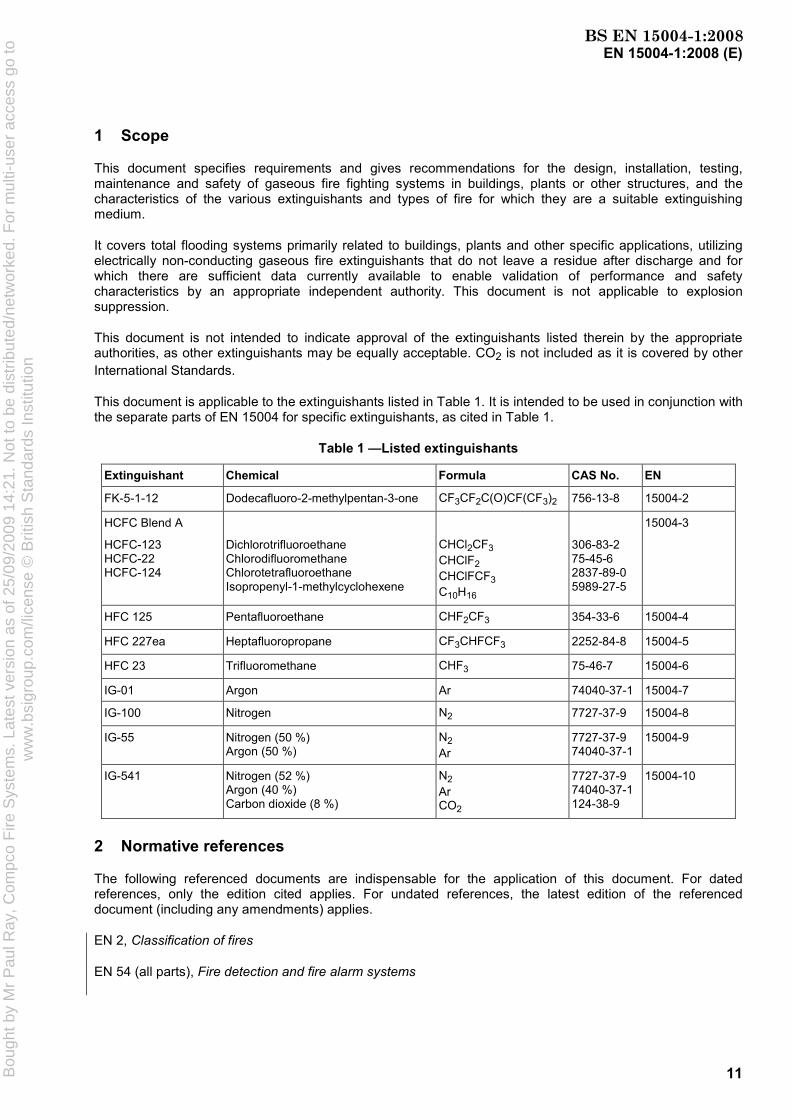
This document is applicable to the extinguishants listed in Table 1. It is intended to be used in conjunction with the separate parts of EN 15004 for specific extinguishants, as cited in Table 1.
Table 1 —Listed extinguishants
Extinguishant Chemical Formula CAS No. EN
FK-5-1-12 Dodecafluoro-2-methylpentan-3-one CF3CF2C(O)CF(CF3)2 756-13-8 15004-2
HCFC Blend A
HCFC-123 HCFC-22 HCFC-124
Dichlorotrifluoroethane Chlorodifluoromethane Chlorotetrafluoroethane Isopropenyl-1-methylcyclohexene
CHCl2CF3 CHClF2 CHClFCF3 C10H16
306-83-2 75-45-6 2837-89-0 5989-27-5
15004-3
HFC 125 Pentafluoroethane CHF2CF3 354-33-6 15004-4
HFC 227ea Heptafluoropropane CF3CHFCF3 2252-84-8 15004-5
HFC 23 Trifluoromethane CHF3 75-46-7 15004-6
IG-01 Argon Ar 74040-37-1 15004-7
IG-100 Nitrogen N2 7727-37-9 15004-8
IG-55 Nitrogen (50 %) Argon (50 %)
N2 Ar
7727-37-9 74040-37-1
15004-9
IG-541 Nitrogen (52 %) Argon (40 %) Carbon dioxide (8 %)
N2 Ar CO2
7727-37-9 74040-37-1 124-38-9
15004-10
2 Normative references
The following referenced documents are indispensable for the application of this document. For dated references, only the edition cited applies. For undated references, the latest edition of the referenced document (including any amendments) applies.
EN 2, Classification of fires
EN 54 (all parts), Fire detection and fire alarm systems
BS EN 15004-1:2008B
ough
t by
Mr
Pau
l Ray
, Com
pco
Fire
Sys
tem
s. L
ates
t ver
sion
as
of 2
5/09
/200
9 14
:21.
Not
to b
e di
strib
uted
/net
wor
ked.
For
mul
ti-us
er a
cces
s go
tow
ww
.bsi
grou
p.co
m/li
cens
e ©
Brit
ish
Sta
ndar
ds In
stitu
tion

EN 15004-1:2008 (E)
12
EN 12094-1, Fixed firefighting systems – Components for gas extinguishing systems – Part 1: Requirements and test methods for electrical automatic control and delay devices
EN 12094-2, Fixed firefighting systems – Components for gas extinguishing systems – Part 2: Requirements and test methods for non-electrical automatic control and delay devices
EN 12094-3, Fixed firefighting systems – Components for gas extinguishing systems – Part 3: Requirements and test methods for manual triggering and stop devices
EN 12094-4, Fixed firefighting systems – Components for gas extinguishing systems – Part 4: Requirements and test methods for container valve assemblies and their actuators
EN 12094-5, Fixed firefighting systems – Components for gas extinguishing systems – Part 5: Requirements and test methods for high and low pressure selector valves and their actuators
EN 12094-6, Fixed firefighting systems – Components for gas extinguishing systems – Part 6: Requirements and test methods for non-electrical disable devices
EN 12094-7, Fixed firefighting systems – Components for gas extinguishing systems – Part 7: Requirements and test methods for nozzles for C02 systems
EN 12094-8, Fixed firefighting systems – Components for gas extinguishing systems – Part 8: Requirements and test methods for connectors
EN 12094-10, Fixed firefighting systems – Components for gas extinguishing systems – Part 10: Requirements and test methods for pressure gauges and pressure switches
EN 12094-11, Fixed firefighting systems – Components for gas extinguishing systems – Part 11: Requirements and test methods for mechanical weighing devices
EN 12094-13, Fixed firefighting systems – Components for gas extinguishing systems – Part 13: Requirements and test methods for check valves and non-return valves
EN 15004-2:2008, Fixed firefighting systems – Gas extinguishing systems – Part 2: Physical properties and system design of gas extinguishing systems for FK-5-1-12, extinguishant (ISO 14520-5, modified)
EN 15004-3:2008, Fixed firefighting systems – Gas extinguishing systems – Part 3: Physical properties and system design of gas extinguishing systems for HCFC Blend A extinguishant (ISO 14250-6, modified)
EN 15004-4,:2008 Fixed firefighting systems – Gas extinguishing systems – Part 4: Physical properties and system design of gas extinguishing systems for HFC 125 extinguishant (ISO 14520-8, modified)
EN 15004-5:2008, Fixed firefighting systems – Gas extinguishing systems – Part 5: Physical properties and system design of gas extinguishing systems for HFC 227ea extinguishant (ISO 14520-9, modified)
EN 15004-6:2008, Fixed firefighting systems – Gas extinguishing systems – Part 6: Physical properties and system design of gas extinguishing systems for HFC 23 extinguishant (ISO 14520-10, modified)
EN 15004-7:2008, Fixed firefighting systems – Gas extinguishing systems – Part 7: Physical properties and system design of gas extinguishing systems for IG-01 extinguishant (ISO 14520-12, modified)
EN 15004-8:2008, Fixed firefighting systems – Gas extinguishing systems – Part 8: Physical properties and system design of gas extinguishing systems for IG-100 extinguishant (ISO 14520-13, modified)
EN 15004-9:2008, Fixed firefighting systems – Gas extinguishing systems – Part 9: Physical properties and system design of gas extinguishing systems for IG-55 extinguishant (ISO 14520-14, modified)
EN 15004-10:2008, Fixed firefighting systems – Gas extinguishing systems – Part 10: Physical properties and system design of gas extinguishing systems for IG-541 extinguishant (ISO 14520-15, modified)
BS EN 15004-1:2008B
ough
t by
Mr
Pau
l Ray
, Com
pco
Fire
Sys
tem
s. L
ates
t ver
sion
as
of 2
5/09
/200
9 14
:21.
Not
to b
e di
strib
uted
/net
wor
ked.
For
mul
ti-us
er a
cces
s go
tow
ww
.bsi
grou
p.co
m/li
cens
e ©
Brit
ish
Sta
ndar
ds In
stitu
tion

EN 15004-1:2008 (E)
13
3 Terms and definitions
For the purposes of this document, the following terms and definitions apply.
NOTE For the purposes of this document, the term “bar” is be taken as “gauge”, unless otherwise indicated. Concentrations or quantities expressed in percentages (%) are taken as by volume, unless otherwise indicated.
3.1 approved acceptable to a relevant authority (see 3.2)
NOTE In determining the acceptability of installations or procedures, equipment or materials, the authority may base acceptance on compliance with the appropriate standards.
3.2 authority organization, office or individual responsible for approving equipment, installations or procedures
3.3 automatic/manual switch means of converting the system from automatic to manual actuation
NOTE This may be in the form of a manual switch on the control panel or other units, or a personnel door interlock. In all cases, this changes the actuation mode of the system from automatic and manual to manual only or vice versa.
3.4 competent person designated person, suitably trained, qualified by knowledge and practical experience and with the necessary instructions to enable the required tests and examinations to be carried out
3.5 extinguishant electrically non-conducting gaseous fire extinguishant that, upon evaporation, does not leave a residue (see Table 1)
3.6 clearance air gap between equipment, including piping and nozzles and unenclosed or uninsulated live electrical components at other than ground potential
3.7 Concentration 3.7.1 design concentration concentration of extinguishant, including a safety factor, required for system design purposes
3.7.2 maximum concentration concentration achieved from the actual extinguishant quantity at the maximum ambient temperature in the protected area
3.7.3 extinguishing concentration minimum concentration of extinguishant required to extinguish a fire involving a particular fuel under defined experimental conditions excluding any safety factor
BS EN 15004-1:2008B
ough
t by
Mr
Pau
l Ray
, Com
pco
Fire
Sys
tem
s. L
ates
t ver
sion
as
of 2
5/09
/200
9 14
:21.
Not
to b
e di
strib
uted
/net
wor
ked.
For
mul
ti-us
er a
cces
s go
tow
ww
.bsi
grou
p.co
m/li
cens
e ©
Brit
ish
Sta
ndar
ds In
stitu
tion

EN 15004-1:2008 (E)
14
3.8 disable device manual shut-off valve installed into the discharge piping downstream of the agent containers; or another type of device that mechanically prevents agent container actuation
NOTE 1 The actuation of this device provides an indication of system isolation.
NOTE 2 The intent is to prevent the discharge of agent into the hazard area when the disable device is activated.
3.9 engineered system system in which the supply of extinguishant stored centrally is discharged through a system of pipes and nozzles in which the size of each section of pipe and nozzle orifice has been calculated in accordance with relevant parts of EN 15004
3.10 fill density mass of extinguishant per unit volume of container
3.11 flooding quantity mass or volume of extinguishant required to achieve the design concentration within the protected volume
3.12 net volume volume enclosed by the building elements around the protected enclosure, minus the volume of any permanent impermeable building elements within the enclosure
3.13 hold time period of time during which a concentration of extinguishant greater than the fire extinguishing concentration surrounds the hazard
3.14 inspection visual check to give reasonable assurance that the extinguishing system is fully charged and operable
NOTE This is done by seeing that the system is in place, that it has not been activated or tampered with, and that there is no obvious physical damage or condition to prevent operation.
3.15 installer legal person that is responsible for the design and installation and is able to ensure that the quality assurance is exercised
3.16 liquefied gas gas or gas mixture (normally a halocarbon) which is liquid at the container pressurization level at room temperature (20 °C)
3.17 lowest observed adverse effect level LOAEL lowest concentration at which an adverse toxicological or physiological effect has been observed
3.18 maintenance combination of all technical, administrative and managerial actions during the life cycle of an item intended to retain it in, or restore it to, a state in which it can perform the required function
BS EN 15004-1:2008B
ough
t by
Mr
Pau
l Ray
, Com
pco
Fire
Sys
tem
s. L
ates
t ver
sion
as
of 2
5/09
/200
9 14
:21.
Not
to b
e di
strib
uted
/net
wor
ked.
For
mul
ti-us
er a
cces
s go
tow
ww
.bsi
grou
p.co
m/li
cens
e ©
Brit
ish
Sta
ndar
ds In
stitu
tion

EN 15004-1:2008 (E)
15
(EN 13306 [2])
3.19 maximum working pressure equilibrium pressure within a container at the maximum working temperature
NOTE 1 For liquefied gases this is at the maximum fill density and may include superpressurization.
NOTE 2 The equilibrium pressure for a container in transit can differ from that in storage within a building.
3.20 no observed adverse effect level NOAEL highest concentration at which no adverse toxicological or physiological effect has been observed
3.21 non-liquefied gas gas or gas mixture (normally an inert gas) which, under service pressure and allowable service temperature conditions, is always present in the gaseous form
3.22 normally occupied area area intended for occupancy
3.23 normally unoccupied area area not normally occupied by people but which may be entered occasionally for brief periods
3.24 pre-engineered system system consisting of a supply of extinguishant of specified capacity coupled to pipework with a balanced nozzle arrangement up to a maximum permitted design
NOTE No deviation is permitted from the limits specified by the manufacturer or authority.
3.25 safety factor multiplier of the agent extinguishing concentration to determine the agent minimum design concentration
3.26 sea level equivalent of agent agent concentration (volume percent) at sea level for which the partial pressure of agent matches the ambient partial pressure of agent at a given altitude
3.27 sea level equivalent of oxygen oxygen concentration (volume percent) at sea level for which the partial pressure of oxygen matches the ambient partial pressure of oxygen at a given altitude
3.28 selector valve valve installed in the discharge piping downstream of the agent containers, to direct the agent to the appropriate hazard enclosure
NOTE It is used where one or more agent containers are arranged to selectively discharge agent to any of several separate hazard enclosures.
BS EN 15004-1:2008B
ough
t by
Mr
Pau
l Ray
, Com
pco
Fire
Sys
tem
s. L
ates
t ver
sion
as
of 2
5/09
/200
9 14
:21.
Not
to b
e di
strib
uted
/net
wor
ked.
For
mul
ti-us
er a
cces
s go
tow
ww
.bsi
grou
p.co
m/li
cens
e ©
Brit
ish
Sta
ndar
ds In
stitu
tion
EN 15004-1:2008 (E)
16
3.29 superpressurization addition of a gas to the extinguishant container, where necessary, to achieve the required pressure for proper system operation
3.30 total flooding system system arranged to discharge extinguishant into an enclosed space to achieve the appropriate design concentration
3.31 unoccupiable area area which cannot be occupied due to dimensional or other physical constraints
EXAMPLE Shallow voids and cabinets.
4 Use and limitations
4.1 General
The design, installation and activities to ensure proper system function of gaseous fire-extinguishing systems shall be performed by those competent in fire extinguishing system technology. Maintenance and installation shall only be done by qualified personnel and companies.
The hazards against which these systems offer protection, and any limitations on their use, shall be contained in the system supplier's design manual.
Total flooding fire-extinguishing systems are used primarily for protection against hazards that are in enclosures or equipment that, in itself, includes an enclosure to contain the extinguishant. The following are typical of such hazards, but the list is not exhaustive:
a) electrical and electronic hazards;
b) telecommunications facilities;
c) flammable and combustible liquids and gases;
d) other high-value assets.
4.2 Extinguishants
Any agent that is to be recognized by this document or proposed for inclusion in this document, shall first be evaluated in respect to environmental aspects by European or other internationally recognized extinguishing agent approval institutions.
NOTE Evaluation can be carried out e.g. in a manner equivalent to the U.S. Environmental Protection Agency's (EPA) SNAP Programme.
The extinguishants referred to in this document are electrically non-conductive media.
The extinguishants and specialized system parameters are each covered individually in the parts of EN 15004 for specific extinguishants. These parts shall be used in conjunction with this document.
Unless relevant testing has been carried out to the satisfaction of the authority, the extinguishants referred to in the specific parts of EN 15004 shall not be used on fires involving the following:
a) chemicals containing their own supply of oxygen, such as cellulose nitrate;
BS EN 15004-1:2008B
ough
t by
Mr
Pau
l Ray
, Com
pco
Fire
Sys
tem
s. L
ates
t ver
sion
as
of 2
5/09
/200
9 14
:21.
Not
to b
e di
strib
uted
/net
wor
ked.
For
mul
ti-us
er a
cces
s go
tow
ww
.bsi
grou
p.co
m/li
cens
e ©
Brit
ish
Sta
ndar
ds In
stitu
tion

EN 15004-1:2008 (E)
17
b) mixtures containing oxidizing materials, such as sodium chlorate or sodium nitrate;
c) chemicals capable of undergoing autothermal decomposition, such as some organic peroxides;
d) reactive metals (such as sodium, potassium, magnesium, titanium and zirconium), reactive hydrides, or metal amides, some of which may react violently with some gaseous extinguishants;
e) environments where significant surface areas exist at temperatures greater than the breakdown temperature of the extinguishing agent and are heated by means other than the fire.
4.3 Electrostatic discharge
Care shall be taken when discharging extinguishant into potentially explosive atmospheres. Electrostatic charging of conductors not bonded to earth may occur during the discharge of extinguishant. These conductors may discharge to other objects with sufficient energy to initiate an explosion. Where the system is used for inerting, pipework shall be adequately bonded and earthed.
4.4 Compatibility with other extinguishants
Mixing of extinguishants in the same container shall be permitted only if the system is approved for use with such a mixture.
Systems employing the simultaneous discharge of different extinguishants to protect the same enclosed space shall not be permitted.
4.5 Temperature limitations
All devices shall be designed for the service they will encounter and shall not readily be rendered inoperative or susceptible to accidental operation. Devices normally shall be designed to function properly from – 20 °C to + 50 °C, or marked to indicate temperature limitations, or in accordance with manufacturer's specifications which shall be marked on the name-plate, or (where there is no name-plate) in the manufacturer's instruction manual.
5 Safety
5.1 Hazard to personnel
Any hazard to personnel created by the discharge of gaseous extinguishants shall be considered in the design of the system, in particular with reference to the hazards associated with particular extinguishants in the supplementary parts of EN 15004. Unnecessary exposure to all gaseous extinguishants shall be avoided.
Adherence to EN 15004 does not remove the user's statutory responsibility to comply with the appropriate safety regulations.
The decomposition products generated by the clean agent breaking down in the presence of very high degrees of heat can be hazardous. All of the present halocarbon agents contain fluorine. In the presence of available hydrogen (from water vapour or the combustion process itself), the main decomposition product is hydrogen fluoride (HF).
These decomposition products have a sharp, acrid odour, even in minute concentrations of only a few parts per million. This characteristic provides a built-in warning system for the agent, but at the same time creates a noxious, irritating atmosphere for those who have to enter the hazard following a fire.
The amount of agent that can be expected to decompose in extinguishing a fire depends to a large extent on the size of the fire, the particular clean agent, the concentration of the agent, and the length of time the agent is in contact with the flame or heated surface. If there is a very rapid build-up of concentration to the critical
BS EN 15004-1:2008B
ough
t by
Mr
Pau
l Ray
, Com
pco
Fire
Sys
tem
s. L
ates
t ver
sion
as
of 2
5/09
/200
9 14
:21.
Not
to b
e di
strib
uted
/net
wor
ked.
For
mul
ti-us
er a
cces
s go
tow
ww
.bsi
grou
p.co
m/li
cens
e ©
Brit
ish
Sta
ndar
ds In
stitu
tion

EN 15004-1:2008 (E)
18
value, then the fire will be extinguished quickly and the decomposition will be limited to the minimum possible with that agent. Should that agent's specific composition be such that it could generate large quantities of decomposition products, and the time to achieve the critical value is lengthy, then the quantity of decomposition products can be quite great. The actual concentration of the decomposition products then depends on the volume of the room in which the fire was burning and on the degree of mixing and ventilation.
Clearly, longer exposure of the agent to high temperatures would produce greater concentrations of these gases. The type and sensitivity of detection, coupled with the rate of discharge, should be selected to minimize the exposure time of the agent to the elevated temperature if the concentration of the breakdown products is to be minimized.
Non-liquefied agents do not decompose measurably in extinguishing a fire. As such, toxic or corrosive decomposition products are not found. However, breakdown products of the fire itself can still be substantial and could make the area untenable for human occupancy.
5.2 Safety precautions
5.2.1 General
As acceptable alternatives to the requirements of 5.2 and 5.3, either the requirements of Annex G for safe personnel exposure guidelines or those requirements specified by appropriate national standards may be followed.
The safety precautions required by this document do not address toxicological or physiological effects associated with the products of combustion caused by fire. The maximum exposure time assumed by the safety precautions in this standard is 5 min. Exposure times longer than 5 min may involve physiological or toxicological effects not addressed by this document.
Non-electrical disable devices shall be approved in accordance with EN 12094-6.
Time delay devices shall be approved in accordance with EN 12094-1 or EN 12094-2.
5.2.1 For normally occupied areas
The minimum safety precautions taken shall be in accordance with Table 2.
Table 2 — Minimum safety precautions
Maximum concentration Time delay device
Automatic/manual switch
Disable device
Up to and including the NOAEL Required Not required Not required
Above the NOAEL and up to the LOAEL Required Required Not required
LOAEL and above Required Required Required
NOTE The intent of this table is to avoid unnecessary exposure of occupants to the discharged extinguishant. Factors such as the time for egress and the risk to the occupants by the fire should be considered when determining the system discharge time delay. Where national standards require other precautions, these should be implemented.
5.2.2 For normally unoccupied areas
The maximum concentration shall not exceed the LOAEL for the extinguishant used unless a disable device is fitted.
It is recommended that systems where the NOAEL is expected to be exceeded be placed in non-automatic mode whilst the room is occupied.
WARNING: Any change to the enclosure volume, or addition or removal of fixed contents that was not covered in the original design will affect the concentration of extinguishant. In such instances the
BS EN 15004-1:2008B
ough
t by
Mr
Pau
l Ray
, Com
pco
Fire
Sys
tem
s. L
ates
t ver
sion
as
of 2
5/09
/200
9 14
:21.
Not
to b
e di
strib
uted
/net
wor
ked.
For
mul
ti-us
er a
cces
s go
tow
ww
.bsi
grou
p.co
m/li
cens
e ©
Brit
ish
Sta
ndar
ds In
stitu
tion
EN 15004-1:2008 (E)
19
system shall be recalculated to ensure that the required design concentration is achieved and the maximum concentration is consistent with Table 2.
5.2.3 For unoccupiable areas
The maximum concentration may exceed the LOAEL for the extinguishant used, without the need for a disable device to be fitted.
5.3 Occupiable areas
In areas which are protected by total flooding systems and which are capable of being occupied, the following shall be provided.
a) time delay devices:
1) for applications where a discharge delay does not significantly increase the threat from fire to life or property, extinguishing systems shall incorporate a pre-discharge alarm with a time delay sufficient to allow personnel evacuation prior to discharge;
2) time delay devices shall be used only for personnel evacuation or to prepare the hazard area for discharge;
b) automatic/manual switch, and disable devices where required in accordance with 5.2;
NOTE Although disable devices are not always required, they are essential in some situations, particularly for some specific maintenance functions.
c) exit routes, which shall be kept clear at all times, and emergency lighting and adequate direction signs to minimize travel distances;
d) outward-swinging self-closing doors which can be opened from the inside, including when locked from the outside;
e) continuous visual and audible alarms at entrances and designated exits inside the protected area and continuous visual alarms outside the protected area which operate until the protected area has been made safe;
f) appropriate warning and instructions signs;
g) where required, pre-discharge alarms within such areas, which are distinctive from all other alarm signals, and which, upon detection of the fire, will operate immediately on commencement of time delay;
h) means for prompt natural or forced-draft ventilation of such areas after any discharge of extinguishant. Forced-draft ventilation will often be necessary.
Care shall be taken to completely dissipate hazardous atmospheres and not just move them to other locations, as most extinguishants are heavier than air;
i) instructions and drills of all personnel within or in the vicinity of protected areas, including maintenance or construction personnel who may be brought into the area, to ensure their correct actions when the system operates.
In addition to the above requirements, the following are recommended:
self-contained breathing apparatus should be supplied and personnel trained in its use;
personnel should not enter the enclosure until it has been verified as being safe to do so.
BS EN 15004-1:2008B
ough
t by
Mr
Pau
l Ray
, Com
pco
Fire
Sys
tem
s. L
ates
t ver
sion
as
of 2
5/09
/200
9 14
:21.
Not
to b
e di
strib
uted
/net
wor
ked.
For
mul
ti-us
er a
cces
s go
tow
ww
.bsi
grou
p.co
m/li
cens
e ©
Brit
ish
Sta
ndar
ds In
stitu
tion

EN 15004-1:2008 (E)
20
5.4 Electrical hazards
Where exposed electrical conductors are present, clearances no smaller than those given in Table 3 shall be provided, where practicable, between the electrical conductors and all parts of the system that may be approached during maintenance. Where these clearance distances cannot be achieved, warning notices shall be provided and a safe system of maintenance work shall be adopted.
The system should be so arranged that all normal operations can be carried out with safety to the operator.
Table 3 — Safety clearances to enable operation, inspection, cleaning, repairs, painting and normal maintenance work to be carried out
Minimum clearance from any point on or about the permanent equipment where a person may be required to standa
Maximum rated voltage To the nearest unscreened live
conductor in air (section clearance) To the nearest part not at earth
potential of an insulatorb supporting a live conductor (ground clearance)
kV m m
15
33
44
66
88
110
132
165
220
275
2,6
2,75
2,90
3,10
3,20
3,35
3,50
3,80
4,30
4,60
2,5
a Measured from position of the feet.
b The term insulator includes all forms of insulating supports, such as pedestal and suspension insulators, bushings, cable sealing ends and the insulating supports of certain types of circuit breaker.
5.5 Electrical earthing
Systems within electrical substations or switchrooms shall be efficiently bonded and earthed to prevent the metalwork becoming electrically charged.
5.6 Electrostatic discharge
The system shall be adequately bonded and earthed to minimize the risk of electrostatic discharge.
6 System design
6.1 General
This clause sets out the requirements for the design of the extinguishing system.
BS EN 15004-1:2008B
ough
t by
Mr
Pau
l Ray
, Com
pco
Fire
Sys
tem
s. L
ates
t ver
sion
as
of 2
5/09
/200
9 14
:21.
Not
to b
e di
strib
uted
/net
wor
ked.
For
mul
ti-us
er a
cces
s go
tow
ww
.bsi
grou
p.co
m/li
cens
e ©
Brit
ish
Sta
ndar
ds In
stitu
tion

EN 15004-1:2008 (E)
21
All ancillary systems and components shall comply with the relevant national or European or International Standards.
6.2 Extinguishant supply
6.2.1 Quantity
6.2.1.1 The amount of extinguishant in the system shall be at least sufficient for the largest single hazard or group of hazards that are to be protected against simultaneously.
6.2.1.2 Where required, the reserve quantity shall be as many multiples of the main supply as the authority considers necessary.
6.2.1.3 Where uninterrupted protection is required, both the main and reserve supply shall be permanently connected to the distribution piping and arranged for easy changeover.
6.2.2 Quality
The extinguishant shall comply with the relevant part of EN 15004.
6.2.3 Container arrangement
6.2.3.1 Arrangements shall be made for container and valve assemblies and accessories to be accessible for inspection, testing and other maintenance when required.
6.2.3.2 Containers shall be adequately mounted and suitably supported according to the systems installation manual so as to provide for convenient individual servicing of the container and its contents.
6.2.3.3 Containers shall be located as near as is practical to the enclosure they protect, preferably outside the enclosure. Containers can be located within the enclosure only if sited so as to minimize the risk of exposure to fire and explosion.
6.2.3.4 Containers shall not be located where they will be subjected to severe weather conditions or to potential damage due to mechanical, chemical or other causes. Where potentially damaging exposure or unauthorized interference are likely, suitable enclosures or guards shall be provided.
NOTE Direct sunlight has the potential to increase the container temperature above that of the surrounding atmospheric temperature.
6.2.4 Storage containers
6.2.4.1 General
Containers shall be designed to hold the specific extinguishant. Containers shall not be charged to a fill density greater than specified in this document relating to the specific extinguishant.
The containers used in these systems shall be designed to meet the requirements of relevant national standards.
Where required, the container and valve assembly should be fitted with a pressure relief device complying with the appropriate national standard.
Container valves shall be approved in accordance with EN 12094-4.
BS EN 15004-1:2008B
ough
t by
Mr
Pau
l Ray
, Com
pco
Fire
Sys
tem
s. L
ates
t ver
sion
as
of 2
5/09
/200
9 14
:21.
Not
to b
e di
strib
uted
/net
wor
ked.
For
mul
ti-us
er a
cces
s go
tow
ww
.bsi
grou
p.co
m/li
cens
e ©
Brit
ish
Sta
ndar
ds In
stitu
tion

EN 15004-1:2008 (E)
22
6.2.4.2 Contents indication
Means shall be provided to indicate that each container is correctly charged.
If pressure gauges/switches or mechanical weighing devices are used these shall be approved in accordance with EN 12094-10 or EN 12094-11.
6.2.4.3 Marking
Each halocarbon container shall have a permanent name-plate or other permanent marking specifying the extinguishant, tare and gross mass, and the superpressurization level (where applicable) of the container. Each inert gas container shall have a permanent marking specifying the extinguishant, pressurization level of the container and nominal volume.
6.2.4.4 Manifolded containers
When two or more containers are connected into the same manifold, automatic means (such as check valves) shall be provided to prevent extinguishant loss from the manifold if the system is operated when any containers are removed, e.g. for maintenance.
Check valves shall be approved in accordance with EN 12094-13.
Containers connected to a common manifold in a system shall be:
a) of the same nominal form and capacity,
b) filled with the same nominal mass of extinguishant,
c) pressurized to the same nominal working pressure.
Different sized storage containers connected to a common manifold may be used for non-liquefied gas containers, provided they are all pressurized to the same nominal working pressure.
6.2.4.5 Operating temperatures
Unless otherwise approved, in-service container operating temperatures for total flooding systems shall not exceed 50 °C nor be less than – 20 °C (see also 7.3.1.).
External heating or cooling should be used to keep the temperature of the storage container within the specified range unless the system is designed for proper operation with operating temperatures outside this range.
6.3 Distribution
6.3.1 General
6.3.1.1 Pipework and fittings shall comply with the appropriate national standards, shall be non-combustible and able to withstand the expected pressures and temperatures without damage.
6.3.1.2 Before final assembly, pipe and fittings shall be inspected visually to ensure they are clean and free of burrs and rust, and that no foreign matter is inside and the full bore is clear. After assembly, the system shall be thoroughly blown through with dry air or other compressed gas.
A dirt trap consisting of a tee with a capped nipple, at least 50 mm long, shall be installed at the end of each pipe run. Drain traps protected against interference by unauthorized personnel should be fitted at the lowest points in the pipework system if there is any possibility of a build up of water.
BS EN 15004-1:2008B
ough
t by
Mr
Pau
l Ray
, Com
pco
Fire
Sys
tem
s. L
ates
t ver
sion
as
of 2
5/09
/200
9 14
:21.
Not
to b
e di
strib
uted
/net
wor
ked.
For
mul
ti-us
er a
cces
s go
tow
ww
.bsi
grou
p.co
m/li
cens
e ©
Brit
ish
Sta
ndar
ds In
stitu
tion

EN 15004-1:2008 (E)
23
6.3.1.3 In systems where valve arrangements introduce sections of closed piping, such sections shall be equipped with the following:
a) indication of extinguishant trapped in piping;
b) means for safe manual venting (see 6.3.1.5);
c) automatic relief of over pressures, where required.
Over-pressure relief devices shall be designed to operate at a pressure not greater than the test pressure of the pipework, or as required by the appropriate national standard.
6.3.1.4 Pressure relief devices, which can include the selector valve, should be fitted so that the discharge, in the event of operation, will not injure or endanger personnel and, if necessary, so that the discharge is piped to an area where it will not become a hazard to personnel.
6.3.1.5 In systems using pressure-operated container valves, automatic means shall be provided to vent any container leakage that could build up pressure in the pilot system and cause unwanted opening of the container valve. The means of pressure venting shall not prevent operation of the container valve.
6.3.1.6 The manifolds to the container and valve assembly shall be hydraulically tested by the manufacturer to a minimum pressure of 1,5 × maximum working pressure (see 3.19), or as required by the appropriate national standards.
6.3.1.7 Adequate protection shall be given to pipes, fittings or support brackets and steelwork that are likely to be affected by corrosion. Special corrosion-resistant materials or coatings shall be used in highly corrosive atmospheres.
6.3.2 Piping
6.3.2.1 Piping shall be of non-combustible material having physical and chemical characteristics such that its integrity under stress can be predicted with reliability. The thickness of the pipe wall shall be calculated in accordance with the relevant national standard. The pressure for this calculation shall be the developed pressure at a maximum storage temperature of not less than 50 °C. If higher operating temperatures are approved for a given system, the design pressure shall be adjusted to the developed pressure at maximum temperature. In performing this calculation, all joint factors and threading, grooving or welding allowances shall be taken into account.
Where a static pressure-reducing device is used in a non-liquefied gas system, the maximum working pressure in the distribution pipework downstream of the device shall be used in the calculation of the downstream pipe wall thickness. If selector valves are used, this lower maximum working pressure shall not be used upstream of the selector valves.
6.3.2.2 Cast iron and non-metallic pipes shall not be used.
6.3.2.3 Flexible tubing or hoses (including connections) shall be of approved materials and shall be suitable for service at the anticipated extinguishant pressure and maximum and minimum temperatures.
Hoses and flexible connectors shall be approved in accordance with EN 12094-8.
6.3.3 Fittings
6.3.3.1 Fittings shall have a minimum rated working pressure equal to or greater than the maximum pressure in the container at 50 °C, or the temperature specified in the national standard, when filled to the maximum allowable fill density for the extinguishant being used. For systems that use a pressure-reducing device in the distribution piping, the fittings downstream of the device shall have a minimum rated working pressure equal to or greater than the maximum anticipated pressure in the downstream piping. If selector valves are used, this lower maximum working pressure shall not be used upstream of the selector valves.
BS EN 15004-1:2008B
ough
t by
Mr
Pau
l Ray
, Com
pco
Fire
Sys
tem
s. L
ates
t ver
sion
as
of 2
5/09
/200
9 14
:21.
Not
to b
e di
strib
uted
/net
wor
ked.
For
mul
ti-us
er a
cces
s go
tow
ww
.bsi
grou
p.co
m/li
cens
e ©
Brit
ish
Sta
ndar
ds In
stitu
tion

EN 15004-1:2008 (E)
24
Cast iron fittings shall not be used.
6.3.3.2 Welding and brazing alloys shall have a melting point above 500 °C.
6.3.3.3 Welding shall be performed in accordance with relevant national standards.
6.3.3.4 Where copper, stainless steel, or other suitable tubing is joined with compression fittings, the manufacturer's pressure/temperature ratings of the fitting shall not be exceeded and care shall be taken to ensure the integrity of the assembly.
6.3.4 Pipe and valve supports
Pipe and valve supports shall be of non-combustible material, shall be suitable for the expected temperature and shall be able to withstand the dynamic and static forces involved. Due allowance shall be made for the stresses induced in the pipe work by temperature variations. Adequate environmental protection shall be given to supports and associated steelwork. The distance between pipe supports shall be as specified in Table 4.
Adequate support shall be provided for nozzles and their reactive forces such that in no case shall the distance from the last support be greater than as follows:
a) ≤ 25 mm pipe ≤ 100 mm;
b) > 25 mm pipe ≤ 250 mm.
Movement of pipework caused by temperature fluctuations arising from environment or the discharge of extinguishant may be considerable, particularly over long lengths, and should be considered in the support fixing methods.
BS EN 15004-1:2008B
ough
t by
Mr
Pau
l Ray
, Com
pco
Fire
Sys
tem
s. L
ates
t ver
sion
as
of 2
5/09
/200
9 14
:21.
Not
to b
e di
strib
uted
/net
wor
ked.
For
mul
ti-us
er a
cces
s go
tow
ww
.bsi
grou
p.co
m/li
cens
e ©
Brit
ish
Sta
ndar
ds In
stitu
tion

EN 15004-1:2008 (E)
25
Table 4 — Maximum pipework spans
Nominal diameter of pipe
DN
Maximum pipework span
m
6 10
0,5 1,0
15 20 25
1,5 1,8 2,1
32 40 50
2,4 2,7 3,4
65 80
100
3,5 3,7 4,3
125 150 200
4,8 5,2 5,8
6.3.5 Valves
6.3.5.1 All valves, gaskets, O-rings, sealants and other valve components shall be constructed of materials that are compatible with the extinguishant and shall be suitable for the envisaged pressures and temperatures.
6.3.5.2 Valves shall be protected against mechanical, chemical or other damage.
6.3.5.3 Special corrosion-resistant materials or coatings shall be used in severely corrosive atmospheres.
6.3.5.4 Selector valves shall be approved in accordance with EN 12094-5.
6.3.6 Nozzles
6.3.6.1 Nozzle choice and location
Nozzles, including nozzles directly attached to containers, shall be approved and shall be located with the geometry of the enclosure taken into consideration.
The type number and placement of nozzles shall be such that:
a) the design concentration is achieved in all parts of the enclosure (see EN 12094-7);
b) the discharge does not unduly splash flammable liquids or create dust clouds that might extend the fire, create an explosion or otherwise adversely affect the occupants;
c) the velocity of discharge does not adversely affect the enclosure or its contents.
Where clogging by foreign materials is possible, the discharge nozzles shall be provided with frangible discs or blow-out caps. These devices shall provide an unobstructed opening upon system operation and shall be designed and arranged so they will not injure personnel.
BS EN 15004-1:2008B
ough
t by
Mr
Pau
l Ray
, Com
pco
Fire
Sys
tem
s. L
ates
t ver
sion
as
of 2
5/09
/200
9 14
:21.
Not
to b
e di
strib
uted
/net
wor
ked.
For
mul
ti-us
er a
cces
s go
tow
ww
.bsi
grou
p.co
m/li
cens
e ©
Brit
ish
Sta
ndar
ds In
stitu
tion

EN 15004-1:2008 (E)
26
Nozzles shall be suitable for the intended use and shall be approved for discharge characteristics in accordance with EN 12094-7, or shall be approved under the procedure described in national, European or International nozzle standards.
Nozzles shall be of adequate strength for use with the expected working pressures, they shall be able to resist nominal mechanical abuse and shall be constructed to withstand expected temperatures without deformation.
Nozzle discharge orifice inserts shall be of corrosion-resistant material.
6.3.6.2 Nozzles in ceiling tiles
In order to minimize the possibility of lifting or displacement of lightweight ceiling tiles, precautions shall be taken to securely anchor tiles for a minimum distance of 1,5 m from each discharge nozzle.
NOTE The discharge velocities created by the design of nozzles can be a factor in the displacement of ceiling tiles.
6.3.6.3 Marking
Discharge nozzles shall be permanently marked to identify the manufacturer and size of the orifice.
6.3.6.4 Filters
The inlet of any nozzle assembly or pressure-reducing assembly which contains an orifice of area less than 7 mm2 shall be provided with an internal filter capable of preventing obstruction of the orifice.
Only filters as approved together with the nozzle shall be used.
6.3.7 Pressure reducing orifice assembly
Pressure reducing orifice assemblies shall be permanently marked to identify the size of the orifice. This marking shall be readily visible after the assembly is installed.
6.4 Detection, actuation and control systems
6.4.1 General
Detection, actuation and control systems may be either automatic or manual. Where they are automatic, provision shall also be made for manual operation.
Detection, actuation, alarm and control systems shall be installed, tested and maintained in accordance with appropriate national standards.
Unless otherwise specified in a national standard, 24 h minimum standby sources of energy shall be used to provide for operation of the detection, signalling, control and actuation requirements of the system.
6.4.2 Automatic detection
Automatic detection shall be by any method or device acceptable to the authority and shall be capable of early detection and indication of heat, flame, smoke, combustible vapours or any abnormal condition in the hazard that is likely to produce fire.
Fire detection components shall be approved in accordance with the relevant part of EN 54 or EN 12094, whichever applies.
NOTE Detectors installed at the maximum approved spacing for fire alarm use can result in excessive delay in extinguishant release, especially where more than one detection device is required to be in alarm before automatic actuation results.
BS EN 15004-1:2008B
ough
t by
Mr
Pau
l Ray
, Com
pco
Fire
Sys
tem
s. L
ates
t ver
sion
as
of 2
5/09
/200
9 14
:21.
Not
to b
e di
strib
uted
/net
wor
ked.
For
mul
ti-us
er a
cces
s go
tow
ww
.bsi
grou
p.co
m/li
cens
e ©
Brit
ish
Sta
ndar
ds In
stitu
tion
EN 15004-1:2008 (E)
27
6.4.3 Operating devices
6.4.3.1 Automatic operation
Automatic systems shall be controlled by automatic fire detection and actuation systems suitable for the system and hazard, and shall also be provided with a means of manual operation.
Electrically operated fire detection systems shall comply with the appropriate national standard. The electric power supply shall be independent of the supply for the hazard area, and shall include an emergency secondary power supply with automatic changeover in case the primary supply fails.
When two or more detectors are used, such as those for detecting smoke or flame, it is preferable for the system to operate only after signals from two detectors have been received.
6.4.3.2 Manual operation
Provision shall be made for manual operation of the fire fighting system by means of a control situated outside the protected space or adjacent to the main exit from the space.
In addition to any means of automatic operation, the system shall be provided with the following:
a) one or more means, remote from the containers, of manual operation;
b) a manual device for providing direct mechanical actuation of the system or an electrical manual release system in which the control equipment monitors for abnormal conditions in the power supply and provides a signal when the power source is inadequate.
Manual operation shall cause simultaneous operation of the appropriate automatically operated valves for extinguishant release and distribution.
NOTE 1 National standards may not require a manual release, or may require the release to operate via the pre-discharge alarms and time delay.
The manual operation device shall incorporate a double action or other safety device to restrict accidental operation. The device shall be provided with a means of preventing operation during maintenance of the system.
NOTE 2 The choice of the means of operation will depend upon the nature of the hazard to be protected. Automatic fire detection and alarm equipment will normally be provided on a manual system to indicate the presence of a fire.
Manual operating devices shall be approved in accordance with EN 12094-3.
6.4.4 Control equipment
6.4.4.1 Electric control equipment
Electric control equipment shall be used to supervise the detecting circuits, manual and automatic releasing circuits, signalling circuits, electrical actuating devices and associated wiring and, when required, cause actuation. The control equipment shall be capable of operation with the number and type of actuating devices utilized.
Electrical automatic control and delay devices shall be approved in accordance with EN 12094-1.
6.4.4.2 Pneumatic control equipment
Where pneumatic control equipment is used, the lines shall be protected against crimping and mechanical damage. Where installations could be exposed to conditions that could lead to loss of integrity of the pneumatic lines, special precautions shall be taken to ensure that no loss of integrity will occur.
BS EN 15004-1:2008B
ough
t by
Mr
Pau
l Ray
, Com
pco
Fire
Sys
tem
s. L
ates
t ver
sion
as
of 2
5/09
/200
9 14
:21.
Not
to b
e di
strib
uted
/net
wor
ked.
For
mul
ti-us
er a
cces
s go
tow
ww
.bsi
grou
p.co
m/li
cens
e ©
Brit
ish
Sta
ndar
ds In
stitu
tion

EN 15004-1:2008 (E)
28
Non-electrical automatic control and delay devices shall be approved in accordance with EN 12094-2.
6.4.5 Operating alarms and indicators
6.4.5.1 Alarms or indicators, or both, shall be used to indicate the operation of the system, hazards to personnel, or failure of any supervised device. The type (audible, visual or olfactory), number, and location of the devices shall be such that their purpose is satisfactorily accomplished. The extent and type of alarms or indicator equipment, or both, shall be approved.
Pneumatic alarm devices shall be approved in accordance with EN 12094-12.
6.4.5.2 Audible and visual pre-discharge alarms shall be provided within the protected area to give positive warning of impending discharge. The operation of the warning devices shall be continued after extinguishant discharge, until positive action has been taken to acknowledge the alarm and proceed with appropriate action.
6.4.5.3 Alarms indicating failure of supervised devices or equipment shall give prompt and positive indication of any failure and shall be distinct from alarms indicating operation or hazardous conditions.
6.4.6 Stop devices
Stop devices, where provided, shall be located within the protected area and shall be located near the means of egress for the area. The stop device shall be a type that requires constant manual force to inhibit system operation. Operation of the hold function shall result in both audible and distinct visual indication of system impairment. Operation of the stop device when the system is in the quiescent state shall result in a fault indication at the control unit. The stop device shall be clearly recognizable for the purpose intended.
Stop devices shall be approved in accordance with EN 12094-3.
7 Extinguishant
7.1 General
This clause sets out the requirements for the specifications, system flow calculations and extinguishant concentrations. It shall be read in conjunction with the appropriate part of EN 15004 for the specific agent.
7.2 Specifications, plans and approvals
7.2.1 Specifications
Specifications for gaseous fire-extinguishing systems shall be prepared under the supervision of a person fully experienced in the design of gaseous extinguishing systems and, where appropriate, with the advice of the authority. The specifications shall include all pertinent items necessary for the proper design of the system such as the designation of the authority, variances from the standard to be permitted by the authority, design criteria, system sequence of operations, the type and extent of the acceptance testing to be performed after installation of the system and owner training requirements. Extinguishant specifications are included in the various parts of EN 15004 for the specific agent.
7.2.2 Working documents
Layout and system proposal documents shall be submitted for approval to the authority before installation or modification begins. The type of documentation required is specified in Annex A.
BS EN 15004-1:2008B
ough
t by
Mr
Pau
l Ray
, Com
pco
Fire
Sys
tem
s. L
ates
t ver
sion
as
of 2
5/09
/200
9 14
:21.
Not
to b
e di
strib
uted
/net
wor
ked.
For
mul
ti-us
er a
cces
s go
tow
ww
.bsi
grou
p.co
m/li
cens
e ©
Brit
ish
Sta
ndar
ds In
stitu
tion
EN 15004-1:2008 (E)
29
7.3 System flow calculations
7.3.1 General
System flow calculations shall be carried out at a nominal extinguishant storage temperature of 20 °C, shall have been validated by an accredited approval authority by appropriate tests as for example described in this document, and shall be properly identified. The system design shall be within the manufacturer's specified limitations (see also Annex H).
NOTE 1 Variations from the nominal 20 °C storage temperature will affect flow conditions used in calculations.
NOTE 2 Pre-engineered systems do not require a flow calculation when used within approved limitations.
7.3.2 Balanced and unbalanced system
7.3.2.1 A balanced system shall be one in which:
a) actual or equivalent pipe lengths from the container to each nozzle are all within 10 % of each other;
b) the discharge rate of each nozzle is equal (see Figure 1).
7.3.2.2 Any system that does not meet these criteria shall be considered to be an unbalanced system (see Figure 2).
7.3.3 Friction losses
Allowance shall be made for the friction losses in pipes and in container valves, dip tubes, flexible connectors, selector valves, time delay devices and other equipment (e.g. pressure-reducing devices) within the flow line.
NOTE The flow of a liquefied gas has been demonstrated to be a two-phase phenomenon, the fluid consisting of a mixture of liquid and vapour, the proportions of which are dependent on pressure and temperature. The pressure drop is non-linear, with an increasing rate of pressure loss as the line pressure reduces by pipe friction.
7.3.4 Pressure drop
The pressure drop shall be calculated using two-phase flow equations for liquefied gases and single-phase flow equations for non-liquefied gases.
NOTE These equations use friction factors and constants dependent on pressure and density obtained empirically. As the equations cannot be solved directly, a computer program is usually used to assist with the large number of iterative calculations in which pipe and nozzle sizes and if appropriate, size of pressure reducing devices, are selected within prescribed pressure losses.
7.3.5 Valves and fittings
Valves, fittings and check valves shall be rated for resistance coefficient or equivalent length in terms of pipe, or tubing sizes with which they will be used. The equivalent length of the cylinder valves shall be listed and shall include syphon tube (where fitted), valve, discharge head, flexible connector and check valve.
BS EN 15004-1:2008B
ough
t by
Mr
Pau
l Ray
, Com
pco
Fire
Sys
tem
s. L
ates
t ver
sion
as
of 2
5/09
/200
9 14
:21.
Not
to b
e di
strib
uted
/net
wor
ked.
For
mul
ti-us
er a
cces
s go
tow
ww
.bsi
grou
p.co
m/li
cens
e ©
Brit
ish
Sta
ndar
ds In
stitu
tion
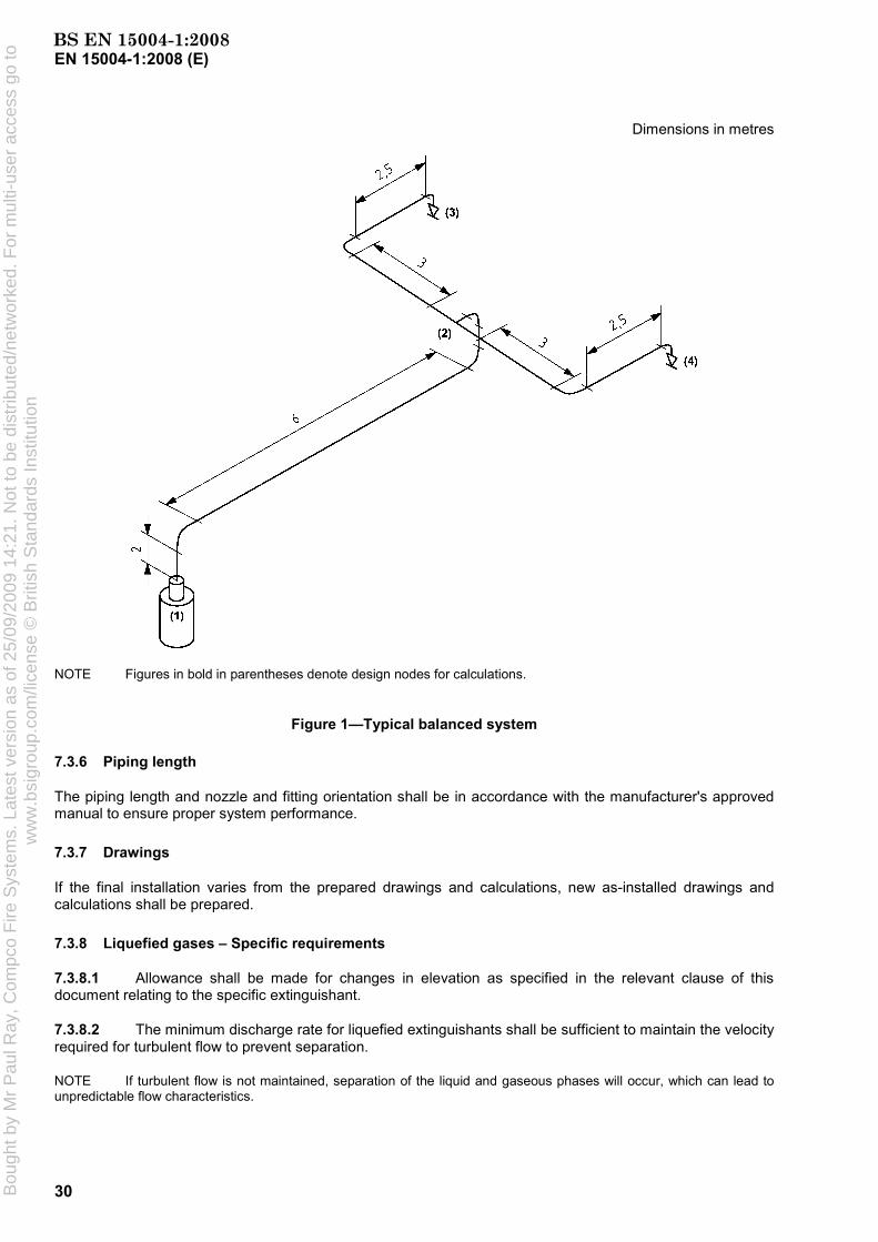
EN 15004-1:2008 (E)
30
Dimensions in metres
NOTE Figures in bold in parentheses denote design nodes for calculations.
Figure 1—Typical balanced system
7.3.6 Piping length
The piping length and nozzle and fitting orientation shall be in accordance with the manufacturer's approved manual to ensure proper system performance.
7.3.7 Drawings
If the final installation varies from the prepared drawings and calculations, new as-installed drawings and calculations shall be prepared.
7.3.8 Liquefied gases – Specific requirements
7.3.8.1 Allowance shall be made for changes in elevation as specified in the relevant clause of this document relating to the specific extinguishant.
7.3.8.2 The minimum discharge rate for liquefied extinguishants shall be sufficient to maintain the velocity required for turbulent flow to prevent separation.
NOTE If turbulent flow is not maintained, separation of the liquid and gaseous phases will occur, which can lead to unpredictable flow characteristics.
BS EN 15004-1:2008B
ough
t by
Mr
Pau
l Ray
, Com
pco
Fire
Sys
tem
s. L
ates
t ver
sion
as
of 2
5/09
/200
9 14
:21.
Not
to b
e di
strib
uted
/net
wor
ked.
For
mul
ti-us
er a
cces
s go
tow
ww
.bsi
grou
p.co
m/li
cens
e ©
Brit
ish
Sta
ndar
ds In
stitu
tion
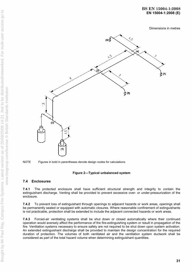
EN 15004-1:2008 (E)
31
Dimensions in metres
NOTE Figures in bold in parentheses denote design nodes for calculations
Figure 2—Typical unbalanced system
7.4 Enclosures
7.4.1 The protected enclosure shall have sufficient structural strength and integrity to contain the extinguishant discharge. Venting shall be provided to prevent excessive over- or under-pressurization of the enclosure.
7.4.2 To prevent loss of extinguishant through openings to adjacent hazards or work areas, openings shall be permanently sealed or equipped with automatic closures. Where reasonable confinement of extinguishants is not practicable, protection shall be extended to include the adjacent connected hazards or work areas.
7.4.3 Forced-air ventilating systems shall be shut down or closed automatically where their continued operation would aversely affect the performance of the fire-extinguishing system or result in propagation of the fire. Ventilation systems necessary to ensure safety are not required to be shut down upon system activation. An extended extinguishant discharge shall be provided to maintain the design concentration for the required duration of protection. The volumes of both ventilated air and the ventilation system ductwork shall be considered as part of the total hazard volume when determining extinguishant quantities.
BS EN 15004-1:2008B
ough
t by
Mr
Pau
l Ray
, Com
pco
Fire
Sys
tem
s. L
ates
t ver
sion
as
of 2
5/09
/200
9 14
:21.
Not
to b
e di
strib
uted
/net
wor
ked.
For
mul
ti-us
er a
cces
s go
tow
ww
.bsi
grou
p.co
m/li
cens
e ©
Brit
ish
Sta
ndar
ds In
stitu
tion

EN 15004-1:2008 (E)
32
All services within the protected enclosure (e.g. fuel and power supplies, heating appliances, paint spraying) that are likely to impair the performance of the extinguishing system should be shut down prior to, or simultaneously with, the discharge of the extinguishant.
7.5 Extinguishant concentration requirements
7.5.1 Flame extinguishment
7.5.1.1 For fire classifications, see EN 2.
7.5.1.2 The minimum Class B design concentration for each extinguishant shall be a demonstrated extinguishing concentration for each Class B fuel multiplied by a safety factor of 1,3. The extinguishing concentration used shall be that demonstrated by the cup burner test, carried out in accordance with the method set out in Annex B, which has been verified with the heptane pan tests detailed in C.6.2. For hazards involving multiple fuels, the value for the fuel requiring the greatest design concentration shall be used. The extinguishing concentration shall be taken as the cup burner value or the heptane pan test value (see Annex C), whichever is greater.
7.5.1.3 The extinguishing concentration for Class A surface fires shall be the greater of the values determined by the wood crib and polymeric sheet fire tests described in Annex C. The minimum design concentration for Class A fires shall be the extinguishing concentration increased by a safety factor of 1,3. For non-cellulosic Class A fuels, higher design concentrations may be required.
CAUTION: It is recognized that the wood crib and polymeric sheet class A fire tests may not adequately indicate extinguishing concentrations suitable for the protection of certain plastic fuel hazards (e.g. electrical and electronic type hazards involving grouped power or data cables such as computer and control room under-floor voids, telecommunication facilities, etc.). An extinguishing concentration not less than that determined in accordance with 7.5.1.3, or not less than 95 % of that determined for heptane in accordance with 7.5.1.2, whichever is greater, should be used under certain conditions. These conditions may include:
a) cable bundles greater than 100 mm in diameter,
b) cable trays with a fill density greater than 20 % of the tray cross-section;
c) horizontal or vertical stacks of cable trays (closer than 250 mm);
d) equipment energized during the extinguishment period where the collective power consumption exceeds 5 kW.
If polymeric sheet fire test data are not available, an extinguishing concentration 95 % of that determined from the heptane fire test shall be used.
The safety factor of 1,3 relates to the increase of 30 % from the extinguishing concentration to the design concentration, which results in additional quantity of agent. Circumstances which may not be adequately covered by this factor (although in some cases they are covered by other requirements in this document) and which may need allowance for additional extinguishant (i.e. more than 30 %) are included but not limited to the following:
a) where leakage occurs from a non-tight enclosure. This is covered in this document by the requirement for a room integrity test and sealing of the enclosure to achieve a defined hold time;
b) where leakage occurs due to doors being opened during or immediately after discharge. This should be covered by operational protocols for individual risks;
c) where it is important to minimize the quantities of toxic or corrosive products of combustion from the fire;
d) where it is important to minimize the toxic or corrosive breakdown products from the extinguishant itself;
BS EN 15004-1:2008B
ough
t by
Mr
Pau
l Ray
, Com
pco
Fire
Sys
tem
s. L
ates
t ver
sion
as
of 2
5/09
/200
9 14
:21.
Not
to b
e di
strib
uted
/net
wor
ked.
For
mul
ti-us
er a
cces
s go
tow
ww
.bsi
grou
p.co
m/li
cens
e ©
Brit
ish
Sta
ndar
ds In
stitu
tion

EN 15004-1:2008 (E)
33
e) where excessive leakage occurs from an enclosure due to expansion of the extinguishant;
f) where hot surfaces, heated by fire or other means, may cause degradation of the extinguishing agent and hence reduce the efficiency of the agent;
g) where metal surfaces, heated by the fire, may act as an ignition source if not adequately cooled during agent discharge and hold time.
In practice, application of this document is likely to result in higher safety factors, for example by the application of gross volumes rather than net volumes and design of systems for minimum anticipated temperatures, rather than those that apply in real conditions.
WARNING: Under certain conditions, it may be dangerous to extinguish a burning gas jet. As a first measure, shut off the gas supply.
7.5.2 Inerting
Inerting concentrations shall be used where conditions for subsequent reflash or explosion could exist. These conditions exist when both:
a) the quantity of fuel permitted in the enclosure is sufficient to develop a concentration equal to or greater than one-half of the lower flammable limit throughout the enclosure; and
b) the volatility of the fuel before the fire is sufficient to reach the lower flammable limit in air (maximum ambient temperature or fuel temperature exceeds the closed cup flash point temperature) or the system response is not rapid enough to detect and extinguish the fire before the volatility of the fuel is increased to a dangerous level as a result of the fire.
The minimum design concentrations used to inert atmospheres involving flammable liquids and gases shall be determined by the test specified in Annex D, plus a safety factor of 10 %.
7.6 Total flooding quantity
7.6.1 General
The amount of extinguishant required to achieve the design concentration shall be calculated from Equations (1) or (2) as appropriate, or from the data in Table 3 of EN 15004-2:2008 and EN 15004-4:2008 to EN 15004-10:2008 and in Table 4 of EN 15004-3:2008.
In addition to these calculated concentration requirements, additional quantities of extinguishant may be required by national standards to compensate for any special conditions that would adversely affect the extinguishing efficiency (see 7.5.1), or if required by the physical characteristics of the extinguishant (see 7.9.1.2).
7.6.2 Liquefied gases
vV
ccQ
−
=100
(1)
where
Q is the total flooding quantity, in kilograms;
c is the design concentration in percent by volume;
V is the net volume of the hazard, in cubic metres (i.e. enclosed volume minus fixed structures impervious to extinguishant);
BS EN 15004-1:2008B
ough
t by
Mr
Pau
l Ray
, Com
pco
Fire
Sys
tem
s. L
ates
t ver
sion
as
of 2
5/09
/200
9 14
:21.
Not
to b
e di
strib
uted
/net
wor
ked.
For
mul
ti-us
er a
cces
s go
tow
ww
.bsi
grou
p.co
m/li
cens
e ©
Brit
ish
Sta
ndar
ds In
stitu
tion

EN 15004-1:2008 (E)
34
v is the specific volume, in cubic metres per kilogram: v = k1 + k2 × T
k1, k2 are constants specific to the extinguishant being used, supplied by the extinguishant manufacturer;
T is the minimum anticipated ambient temperature of the protected volume, in degrees Celsius.
7.6.3 Non-liquefied gas
−
=c
nlvVQ
100100 (2)
where
Q is the total flooding quantity, in kilograms;
c is the design concentration, in percent by volume;
V is the net volume of hazard, in cubic metres (i.e. enclosed volume minus fixed structures impervious to extinguishant);
v is the specific volume, in cubic metres per kilogram: v = k1 + k2 × T
k1, k2 are constants specific to the extinguishant being used, supplied by the extinguishant manufacturer;
T is the minimum anticipated temperature of the protected volume, in degrees Celsius.
NOTE For some purposes (e.g. filling of containers) it may be convenient to express the flooding quantity as volume at given reference (standard) conditions. For those cases the total flooding quantity is equivalent to
RvQQ ×=R
where
QR is the total flooding quantity, in cubic metres, expressed at ambient pressure (1,013 bar absolute) and TR;
Q is the total flooding quantity, in kilograms;
vR is the specific volume at reference temperature, in cubic metres per kilogram: vR = k1 + k2 × TR
k1, k2 are constants specific to the extinguishant being used, supplied by the extinguishment manufacturer;
TR is the reference temperature, in degrees Celsius.
7.7 Altitude adjustment
The design quantity of the extinguishant shall be adjusted to compensate only for ambient pressures that vary more than 11 % (equivalent to approximately 1 000 m of elevation change) from standard sea level pressure (1,013 bar absolute). The ambient pressure is affected by changes in altitude, pressurization or depressurization of the protected enclosure, and weather-related barometric pressure changes. The extinguishant quantity is determined by multiplying the quantity determined in 7.6 by the ratio of the average
BS EN 15004-1:2008B
ough
t by
Mr
Pau
l Ray
, Com
pco
Fire
Sys
tem
s. L
ates
t ver
sion
as
of 2
5/09
/200
9 14
:21.
Not
to b
e di
strib
uted
/net
wor
ked.
For
mul
ti-us
er a
cces
s go
tow
ww
.bsi
grou
p.co
m/li
cens
e ©
Brit
ish
Sta
ndar
ds In
stitu
tion

EN 15004-1:2008 (E)
35
ambient enclosure pressure to the standard sea level pressure. Correction factors for gaseous agents are shown in Table 5.
Table 5 — Correction factors
Equivalent altitude
m
Correction factor
– 1 000 0
1 000
1,130 1,000 0,885
1 500 2 000 2 500
0,830 0,785 0,735
3 000 3 500 4 000 4 500
0,690 0,650 0,610 0,565
7.8 Duration of protection
7.8.1 It is important that an effective extinguishant concentration not only be achieved, but is maintained for a sufficient period of time to allow effective emergency action. This is equally important in all classes of fires since a persistent ignition source (e.g. an arc, heat source, oxyacetylene torch or "deep-seated" fire) can lead to resurgence of the initial event once the extinguishant has dissipated.
7.8.2 It is essential to determine the likely period during which the extinguishing concentration will be maintained within the protected enclosure. This is known as the hold time. The predicted hold time shall be determined by the door fan test specified in Annex E, or a full discharge test based on the following criteria:
a) at the start of the hold time, the concentration throughout the enclosure shall be the design concentration;
b) at the end of the hold time, the extinguishant concentration at 10 %, 50 % and 90 % of the enclosure height shall be not less than 85 % of the design concentration;
c) the hold time shall be not less than 10 min, unless otherwise specified by the authority.
7.9 System performance
7.9.1 Discharge time
7.9.1.1 Liquefied extinguishant
The liquefied extinguishant discharge shall be completed as quickly as possible to suppress the fire and limit the formation of decomposition products. In no case shall the discharge time required to achieve 95 % of the design concentration exceed 10 s at 20 °C, or as otherwise required by the authority.
The discharge time period is defined as the time required to discharge from the nozzles 95 % of the extinguishant mass required to achieve the design concentration at 20 °C. For liquefied extinguishants, this can be approximated as the interval between the first appearance of liquid at the nozzle and the time when the discharge becomes predominantly gaseous. Flow calculations performed in accordance with 7.3 or with the approved pre-engineered systems instruction manuals shall be used to demonstrate compliance with this clause.
BS EN 15004-1:2008B
ough
t by
Mr
Pau
l Ray
, Com
pco
Fire
Sys
tem
s. L
ates
t ver
sion
as
of 2
5/09
/200
9 14
:21.
Not
to b
e di
strib
uted
/net
wor
ked.
For
mul
ti-us
er a
cces
s go
tow
ww
.bsi
grou
p.co
m/li
cens
e ©
Brit
ish
Sta
ndar
ds In
stitu
tion

EN 15004-1:2008 (E)
36
7.9.1.2 Non-liquefied extinguishant
The discharge time required to achieve 95 % of the design concentration for non-liquefied extinguishants shall not exceed 60 s at 20 °C, or as otherwise required by the authority. Flow calculations performed in accordance with 7.3 or with the approved pre-engineered systems instruction manuals shall be used to demonstrate compliance with this clause.
7.9.2 Extended discharge
When an extended discharge is necessary, the rate shall be sufficient to maintain the desired concentration for the required hold time.
8 Commissioning and acceptance
8.1 General
This clause sets out the minimum requirements for the commissioning and acceptance of the gaseous extinguishing system.
8.2 Tests
8.2.1 General
The completed system shall be reviewed and tested by a competent person to meet the approval of the authority. Only equipment and devices designed to national standards shall be used in the systems. To determine that the system has been properly installed and will function as specified, the tests specified in 8.2.2 to 8.2.9 shall be performed.
8.2.2 Enclosure check
Determine that the protected enclosure is in general conformance with the plans.
8.2.3 Review of mechanical components
8.2.3.1 The piping distribution system shall be inspected to determine that it is in compliance with the design and installation documents.
8.2.3.2 Nozzles and pipe size and, if appropriate, pressure-reducing devices, shall be in accordance with system drawings. The means for pipe size reduction and attitudes of tees shall be checked for conformance to the design.
8.2.3.3 Piping joints, discharge nozzles and piping supports shall be securely fastened to prevent unacceptable vertical or lateral movement during discharge. Discharge nozzles shall be installed in such a manner that piping cannot become detached during discharge.
8.2.3.4 During assembly, the piping distribution system shall be inspected internally to detect the possibility of any oil or particulate matter which could soil the hazard area or affect the extinguishant distribution due to a reduction in the effective nozzle orifice area.
8.2.3.5 The discharge nozzles shall be oriented in such a manner that optimum extinguishant dispersal can be effected.
8.2.3.6 If nozzle deflectors are installed, they shall be positioned to obtain the maximum benefit.
BS EN 15004-1:2008B
ough
t by
Mr
Pau
l Ray
, Com
pco
Fire
Sys
tem
s. L
ates
t ver
sion
as
of 2
5/09
/200
9 14
:21.
Not
to b
e di
strib
uted
/net
wor
ked.
For
mul
ti-us
er a
cces
s go
tow
ww
.bsi
grou
p.co
m/li
cens
e ©
Brit
ish
Sta
ndar
ds In
stitu
tion

EN 15004-1:2008 (E)
37
8.2.3.7 The discharge nozzles, piping, and mounting brackets shall be installed in such a manner that they will not potentially cause injury to personnel. Extinguishant shall not directly impinge on areas where personnel may be found in the normal work area, or on any loose objects or shelves, cabinet tops, or similar surfaces where loose objects could be present and become missiles.
8.2.3.8 All extinguishant storage containers shall be properly located in accordance with 'approved for construction' set of system drawings.
8.2.3.9 All containers and mounting brackets shall be securely fastened in accordance with the manufacturer's requirements.
8.2.3.10 A discharge test for extinguishants is generally not recommended. However, if a discharge test is to be conducted, the mass of extinguishant shall be determined by weighing or other approved methods. Concentration measurements should be made at a minimum of three points, one at the highest hazard level.
Other assessment methods may normally be used to reduce unnecessary discharge into the environment, for example, the door fan pressurization test specified in Annex E. However, a discharge test may be conducted if acceptable to the authority.
8.2.3.11 An adequate quantity of extinguishant to produce the desired specified concentration shall be provided. The actual enclosure volumes shall be checked against those indicated on the system drawings to ensure the proper quantity of extinguishant. Fan rundown and damper closure time shall be taken into consideration.
8.2.3.12 Unless the total piping contains not more than one change in direction fitting between the storage container and the discharge nozzle, and unless all piping has been physically checked for tightness, the following tests shall be carried out:
a) all open-ended piping shall be pneumatically tested in a closed circuit for a period of 10 min at 3 bar. At the end of 10 min, the pressure drop shall not exceed 20 % of the test pressure;
b) all closed-section pipework and pipework upstream of pressure reducing devices shall be hydrostatically tested to a minimum of 1,5 × the maximum working pressure for 2 min during which there shall be no leakage. On completion of the test, the pipework shall be purged to remove moisture.
It is recommended that hydrostatic testing be carried out at the manufacturer's works where practicable.
WARNING — Pneumatic pressure testing creates a potential risk of injury to personnel in the area, as a result of airborne projectiles if rupture of the piping system occurs. Prior to conducting the pneumatic pressure test, the protected area shall be evacuated and appropriate safeguards shall be provided for test personnel.
8.2.3.13 A test using nitrogen, or a suitable alternative, shall be performed on the piping network to verify that flow is continuous and that the piping and nozzles are unobstructed.
8.2.4 Review of enclosure integrity
All total flooding systems shall have the enclosure checked to locate and then effectively seal any significant air leaks that could result in a failure of the enclosure to hold the specified extinguishant concentration level for the specified holding period (see also 7.4.1). Unless otherwise required by the authority, the test specified in Annex E shall be used.
8.2.5 Review of electrical components
8.2.5.1 All wiring systems shall be properly installed in compliance with the appropriate national standard and the system drawings. The AC and DC wiring shall not be combined in a common conduit unless properly shielded and earthed.
BS EN 15004-1:2008B
ough
t by
Mr
Pau
l Ray
, Com
pco
Fire
Sys
tem
s. L
ates
t ver
sion
as
of 2
5/09
/200
9 14
:21.
Not
to b
e di
strib
uted
/net
wor
ked.
For
mul
ti-us
er a
cces
s go
tow
ww
.bsi
grou
p.co
m/li
cens
e ©
Brit
ish
Sta
ndar
ds In
stitu
tion
EN 15004-1:2008 (E)
38
8.2.5.2 All field circuitry shall be tested for ground fault and short circuit condition. When testing field circuitry, all electronic components (such as smoke and flame detectors or special electronic equipment for other detectors, or their mounting bases) shall be removed and jumpers properly installed to prevent the possibility of damage within these devices. Replace components after testing the circuits.
8.2.5.3 Adequate and reliable primary standby sources of energy which comply with 6.4 shall be used to provide for operation of the detection, signalling, control and actuation requirements of the system.
8.2.5.4 All auxiliary functions (such as alarm sounding or displaying devices, remote annunciators, air handling shutdown, power shutdown, etc.) shall be checked for proper operation in accordance with system requirements and design specifications.
Alarm devices shall be installed so that they are audible and visible under normal operating and environmental conditions.
Where possible, all air-handling and power cut-off controls should be of the type that once interrupted require manual restart to restore power.
8.2.5.5 Check that for systems using alarm silencing, this function does not affect other auxiliary functions such as air handling or power cut-off where they are required in the design specification.
8.2.5.6 Check the detection devices to ensure that the types and locations are as specified in the system drawings and are in accordance with the manufacturer's requirements.
8.2.5.7 Check that manual release devices are properly installed and are readily accessible, accurately identified and properly protected to prevent damage.
8.2.5.8 Check that all manual release devices used to release extinguishants require two separate and distinct actions for operation. They shall be properly identified. Particular care shall be taken where manual release devices for more than one system are in close proximity and could be confused or the wrong system actuated. Manual release devices in this instance shall be clearly identified as to which hazard enclosure they protect.
8.2.5.9 Check that for systems with a main/reserve capability, the main/reserve switch is properly installed, readily accessible and clearly identified.
8.2.5.10 Check that for systems using stop devices requiring constant manual force, these are properly installed, readily accessible within the hazard area and clearly identified.
8.2.5.11 Check that the control panel is properly installed and readily accessible.
8.2.6 Preliminary functional tests
8.2.6.1 Where a system is connected to a remote central alarm station, notify the station that the fire system test is to be conducted and that an emergency response by the fire department or alarm station personnel is not required. Notify all concerned personnel at the end-user's facility that a test is to be conducted and instruct them as to the sequence of operation.
8.2.6.2 Disable or remove each extinguishant storage container release mechanism and selector valves, where fitted, so that activation of the release circuit will not release extinguishant. Reconnect the release circuit with a functional device in lieu of each extinguishant storage container release mechanism.
For electrically actuated release mechanisms, these devices may include suitable lamps, flash bulbs or circuit breakers. Pneumatically actuated release mechanisms may include pressure gauges. Refer to the manufacturer's recommendations in all cases.
8.2.6.3 Check each resettable detector for proper response.
BS EN 15004-1:2008B
ough
t by
Mr
Pau
l Ray
, Com
pco
Fire
Sys
tem
s. L
ates
t ver
sion
as
of 2
5/09
/200
9 14
:21.
Not
to b
e di
strib
uted
/net
wor
ked.
For
mul
ti-us
er a
cces
s go
tow
ww
.bsi
grou
p.co
m/li
cens
e ©
Brit
ish
Sta
ndar
ds In
stitu
tion

EN 15004-1:2008 (E)
39
8.2.6.4 Check that polarity has been observed on all polarized alarm devices and auxiliary relays.
8.2.6.5 Check that all required end-of-line devices have been installed.
8.2.6.6 Check all supervised circuits for correct fault response.
8.2.7 System functional operational test
8.2.7.1 Operate the detection initiating circuit(s). All alarm functions shall occur according to the design specifications.
8.2.7.2 Operate the necessary circuit to initiate a second alarm circuit if present. Verify that all second alarm functions occur according to design specifications.
8.2.7.3 Operate the manual release device. Verify that manual release functions occur according to design specifications.
8.2.7.4 Where appropriate, operate the stop device. Verify that functions occur according to the design specifications. Confirm that visual and audible supervisory signals are received at the control panel.
8.2.7.5 Check the function of all resettable valves and activators, unless testing the valve will release extinguishant.
"One-shot" valves, such as those incorporating frangible discs, should not be tested.
8.2.7.6 Check pneumatic equipment, where fitted, for integrity to ensure proper operation.
8.2.8 Remote monitoring operations (if applicable)
8.2.8.1 Disconnect the primary power supply, then operate one of each type of input device while on standby power. Verify that an alarm signal is received at the remote panel after the device is operated. Reconnect the primary power supply.
8.2.8.2 Operate each type of alarm condition and verify receipt of fault condition at the remote station.
8.2.9 Control panel primary power source
8.2.9.1 Verify that the control panel is connected to a dedicated unswitched circuit and is labelled properly. This panel shall be readily accessible but access shall be restricted to authorized personnel only.
8.2.9.2 Test a primary power failure in accordance with the manufacturer's specification, with the system fully operated on standby power.
8.2.10 Completion of functional tests
When all functional tests are complete (8.2.6 to 8.2.9), reconnect each storage container so that activation of the release circuit will release the extinguishant. Return the system to its fully operational design condition. Notify the central alarm station and all concerned personnel at the end-user's facility that the fire system test is complete and that the system has been returned to full service condition by following the procedures specified in the manufacturers' specifications.
8.3 Completion certificate and documentation
The installer shall provide to the user a completion certificate, a complete set of instructions, calculations and drawings showing the system as-installed, and a statement that the system complies with all the appropriate requirements of this document, and giving details of any departure from appropriate recommendations. The
BS EN 15004-1:2008B
ough
t by
Mr
Pau
l Ray
, Com
pco
Fire
Sys
tem
s. L
ates
t ver
sion
as
of 2
5/09
/200
9 14
:21.
Not
to b
e di
strib
uted
/net
wor
ked.
For
mul
ti-us
er a
cces
s go
tow
ww
.bsi
grou
p.co
m/li
cens
e ©
Brit
ish
Sta
ndar
ds In
stitu
tion

EN 15004-1:2008 (E)
40
certificate shall give the design concentrations and, if carried out, reports of any additional test including the door fan test.
9 Inspection, maintenance, testing and training
9.1 General
This clause specifies the requirements for inspection, maintenance and testing of a gaseous fire-extinguishing system and for the training of inspection and maintenance personnel.
IMPORTANT — In accordance with the European legislation, the requirements of this clause are reserved to the national body of rules and regulations of each Member State.
9.2 Inspection
9.2.1 General
9.2.1.1 At least annually, or more frequently as required by the authority, all systems shall be thoroughly inspected and tested for proper operation by competent personnel.
9.2.1.2 The inspection report with recommendations shall be filed with the owner.
9.2.1.3 At least every 6 months, the container contents shall be checked as follows:
a) Liquefied gases: for halocarbon extinguishants, if a container shows a loss in extinguishant quantity of more than 5 % or a loss in pressure (adjusted for temperature) of more than 10 %, it shall be refilled or replaced.
b) Non-liquefied gases: for inert gas extinguishants, pressure is an indication of extinguishant quantity. Unless otherwise specified by the authority, if an inert gas extinguishant container shows a loss in pressure (adjusted for temperature) of more than 5 %, it shall be refilled or replaced. Where container pressure gauges or weight-monitoring devices are used for this purpose, they shall be compared to a separate calibrated device at least annually.
9.2.1.4 All extinguishant removed from containers during service or maintenance procedures shall be collected and recycled, or disposed of in an environmentally sound manner, and in accordance with existing laws and regulations.
Inert gas mixtures based on those gases normally found in the earth's atmosphere are exempted from this requirement.
9.2.1.5 The date of inspection and the name of the person performing the inspection shall be recorded on a tag attached to the container.
9.2.2 Container
Containers shall be subjected to periodical tests as required by the relevant national standard.
9.2.3 Hose
All system hoses shall be examined annually for damage. If visual examination shows any defect, the hose shall be replaced.
BS EN 15004-1:2008B
ough
t by
Mr
Pau
l Ray
, Com
pco
Fire
Sys
tem
s. L
ates
t ver
sion
as
of 2
5/09
/200
9 14
:21.
Not
to b
e di
strib
uted
/net
wor
ked.
For
mul
ti-us
er a
cces
s go
tow
ww
.bsi
grou
p.co
m/li
cens
e ©
Brit
ish
Sta
ndar
ds In
stitu
tion

EN 15004-1:2008 (E)
41
9.2.4 Enclosures
9.2.4.1 At least every 12 months it shall be determined whether boundary penetration or other changes to the protected enclosure have occurred that could affect leakage and extinguishant performance. If this cannot be visually determined, it shall be positively established by repeating the test for enclosure integrity in accordance with Annex E.
9.2.4.2 Where the integrity test reveals increased leakage that would result in an inability to retain the extinguishant for the required period, remedial action shall be carried out.
9.2.4.3 Where it is established that changes to the volume of the enclosure or to the type of hazard within the enclosure, or both, have occurred, the system shall be redesigned to provide the original degree of protection.
It is recommended that the type of hazard within the enclosure and the volume it occupies, be regularly checked to ensure that the required concentration of extinguishant can be achieved and maintained.
9.3 Maintenance
9.3.1 General
The installer shall provide the user with instructions for use specifying the requirements for inspection and the training of personnel for personal safety measures. Information on residual risks shall be added where necessary.
The user shall carry out a programme of inspection, arrange a service schedule, and keep records of the inspections and servicing.
NOTE The continued capability for effective performance of a fire fighting system depends on fully adequate service procedures with, where possible, periodic testing.
Installers shall provide the user with a record in which inspection and service details can be entered.
9.3.2 User's programme of inspection
The installer shall provide the user with an inspection programme for the system and components. The programme shall include instructions on the action to be taken in respect of faults.
The user's inspection programme is intended to detect faults at an early stage to allow rectification before the system may have to operate. A suitable programme is as follows:
a) Weekly: Visually check the hazard and the integrity of the enclosure for changes which might reduce the efficiency of the system. Carry out a visual check that there is no obvious damage to pipework and that all operating controls and components are properly set and undamaged. Check pressure gauges and weighing devices, if fitted, for correct reading and take the appropriate action specified in the users' manual.
b) Monthly: Check that all personnel who may have to operate the equipment or system are properly trained and authorized to do so and, in particular, that new employees have been instructed in its use.
9.3.3 Service schedule
A service schedule shall include requirements for periodic inspection and test for the complete installed system, including pressurized containers, as specified in the appropriate national standards.
The schedule shall be carried out by a competent person who shall provide to the user a signed, dated report of the inspection, advising any rectification carried out or needed.
BS EN 15004-1:2008B
ough
t by
Mr
Pau
l Ray
, Com
pco
Fire
Sys
tem
s. L
ates
t ver
sion
as
of 2
5/09
/200
9 14
:21.
Not
to b
e di
strib
uted
/net
wor
ked.
For
mul
ti-us
er a
cces
s go
tow
ww
.bsi
grou
p.co
m/li
cens
e ©
Brit
ish
Sta
ndar
ds In
stitu
tion

EN 15004-1:2008 (E)
42
During servicing, every care and precaution shall be taken to avoid release of extinguishant. A suitable schedule is provided in Annex F.
9.4 Training
All persons who may be expected to inspect, test, maintain or operate fire-extinguishing systems shall be trained and kept adequately trained in the functions they are expected to perform.
Personnel working in an enclosure protected by a gaseous extinguishant shall receive training in the operation and use of the system, in particular regarding safety issues.
BS EN 15004-1:2008B
ough
t by
Mr
Pau
l Ray
, Com
pco
Fire
Sys
tem
s. L
ates
t ver
sion
as
of 2
5/09
/200
9 14
:21.
Not
to b
e di
strib
uted
/net
wor
ked.
For
mul
ti-us
er a
cces
s go
tow
ww
.bsi
grou
p.co
m/li
cens
e ©
Brit
ish
Sta
ndar
ds In
stitu
tion

EN 15004-1:2008 (E)
43
Annex A (normative)
Working documents
A.1 General
These documents shall be prepared only by persons fully experienced in the design of extinguishing systems. Deviation from these documents shall require permission from the authority.
A.2 Working documents
Working documents shall include the following items:
a) drawings, to an indicated scale of extinguishant distribution system, including containers, location of containers, piping and nozzles, valves and pressure-reducing devices and pipe hanger spacing;
b) name of owner and occupant;
c) location of building in which hazard is located;
d) location and construction of protected enclosure walls and partitions;
e) enclosure cross-section, full height or schematic diagram, including raised access floor and suspended ceiling;
f) type of extinguishant being used;
g) extinguishing or inerting concentration, design concentration and maximum concentration;
h) description of occupancies and hazards to be protected against;
i) specification of containers used, including capacity, storage pressure and mass including extinguishant;
j) description of nozzle(s) used, including inlet size, orifice port configuration, and orifice size/code and orifice size of pressure-reducing devices, if applicable;
k) description of pipes, valves and fittings used, including material specifications, grade and pressure rating;
l) equipment schedule or bill of materials for each piece of equipment or device, showing device name, manufacturer, model or part number, quantity and description;
m) isometric view of extinguishant distribution system, showing the length and diameter of each pipe segment and node reference numbers relating to the flow calculations;
n) enclosure pressurization and venting calculations;
o) description of fire detection, actuation and control systems.
BS EN 15004-1:2008B
ough
t by
Mr
Pau
l Ray
, Com
pco
Fire
Sys
tem
s. L
ates
t ver
sion
as
of 2
5/09
/200
9 14
:21.
Not
to b
e di
strib
uted
/net
wor
ked.
For
mul
ti-us
er a
cces
s go
tow
ww
.bsi
grou
p.co
m/li
cens
e ©
Brit
ish
Sta
ndar
ds In
stitu
tion

EN 15004-1:2008 (E)
44
A.3 Specific details
A.3.1 Pre-engineered systems
For pre-engineered systems, the end-user shall be provided with the manufacturer's system design and maintenance information.
A.3.2 Engineered systems
For engineered systems, the end-user shall be provided with the manufacturer's system design and maintenance information.
Details of the system shall include the following:
a) information and calculations on the amount of extinguishant;
b) container storage pressure and extinguishant quantity;
c) capacity of the container;
d) the location, type and flow rate of each nozzle, including equivalent orifice area and pressure-reducing devices, if applicable;
e) the location, size and equivalent lengths or resistance coefficients of pipe fittings and hoses; pipe size reduction and orientation of tees shall be clearly indicated;
f) the location and size of the storage facility.
Information shall be submitted pertaining to the location and function of the detection devices, operating devices, auxiliary equipment and electrical circuitry, if used. Apparatus and devices shall be identified. Any special features shall be adequately explained. The version of the flow calculation program shall be identified on the computer calculation printout.
BS EN 15004-1:2008B
ough
t by
Mr
Pau
l Ray
, Com
pco
Fire
Sys
tem
s. L
ates
t ver
sion
as
of 2
5/09
/200
9 14
:21.
Not
to b
e di
strib
uted
/net
wor
ked.
For
mul
ti-us
er a
cces
s go
tow
ww
.bsi
grou
p.co
m/li
cens
e ©
Brit
ish
Sta
ndar
ds In
stitu
tion

EN 15004-1:2008 (E)
45
Annex B (normative)
Determination of flame-extinguishing concentration of gaseous
extinguishants by the cup burner method
B.1 General
This Annex specifies the minimum requirements for determining the flame-extinguishing concentration of a gaseous extinguishant in air for flammable liquids and gases, employing the cup burner apparatus.
B.2 Principle
Diffusion flames of fuels burning in a round reservoir (cup), centrally positioned in a coaxially flowing air stream, are extinguished by addition of a gaseous extinguishant to the air.
B.3 Requirements for apparatus
B.3.1 General
The cup burner apparatus for these measurements shall be arranged and constructed as in Figure B.1, with the dimensions shown; the tolerance for all dimensions shall be 5 % unless otherwise indicated.
BS EN 15004-1:2008B
ough
t by
Mr
Pau
l Ray
, Com
pco
Fire
Sys
tem
s. L
ates
t ver
sion
as
of 2
5/09
/200
9 14
:21.
Not
to b
e di
strib
uted
/net
wor
ked.
For
mul
ti-us
er a
cces
s go
tow
ww
.bsi
grou
p.co
m/li
cens
e ©
Brit
ish
Sta
ndar
ds In
stitu
tion

EN 15004-1:2008 (E)
46
Dimensions in millimetres
Key
1 diffuser
2 air/extinguishant in
3 fuel in
4 grind inner surface of cup a 45° angle
Figure B.1 — Cup burner apparatus
B.3.2 Cup
The cup shall be round and shall be constructed of glass, quartz or steel. It shall have an outside diameter in the range of 28 mm to 31 mm, with a wall thickness of 1 mm to 2 mm. It shall have a 45° chamfer into the top edge of the cup. There shall be a means of measuring the temperature of the fuel inside the cup at a location 2 mm to 5 mm below the top of the cup. The cup shall be substantially similar in shape to the example shown in Figure B.1. A cup intended for use with gaseous fuels shall have means of attaining a uniform gas flow at the top of the cup (e.g. the cup may be packed with refractory materials).
B.3.3 Chimney
The chimney shall be of round glass or quartz construction. It shall have an inside diameter of 85 mm ± 2 mm and a wall thickness of 2 mm to 5 mm, with a height of 535 mm ± 5 mm.
BS EN 15004-1:2008B
ough
t by
Mr
Pau
l Ray
, Com
pco
Fire
Sys
tem
s. L
ates
t ver
sion
as
of 2
5/09
/200
9 14
:21.
Not
to b
e di
strib
uted
/net
wor
ked.
For
mul
ti-us
er a
cces
s go
tow
ww
.bsi
grou
p.co
m/li
cens
e ©
Brit
ish
Sta
ndar
ds In
stitu
tion
EN 15004-1:2008 (E)
47
B.3.4 Diffuser
The diffuser shall have a means of fitting to the bottom end of the chimney. It shall have a means of admitting a premixed stream of air and extinguishant; and have a means of uniformly distributing the air/extinguishant flow across the cross-section of the chimney. The temperature of the air/extinguishant mixture within the diffuser shall be 25 °C ± 10 °C, measured with a calibrated temperature sensor.
B.3.5 Fuel supply
A liquid fuel supply shall be capable of delivering liquid fuel to the cup while maintaining a fixed, but adjustable, liquid level therein.
A gaseous fuel supply shall be capable of delivering a fuel gas at a controlled and fixed rate to the cup.
B.3.6 Manifold
A manifold shall receive air and extinguishant and deliver them as a single mixed stream to the diffuser.
B.3.7 Air supply
A means for delivering air to the manifold shall allow adjustment of the air flow rate. It shall have a calibrated means of measuring the air flow rate.
B.3.8 Extinguishant supply
A means for delivering extinguishant to the manifold shall allow adjustment of the extinguishant flow rate. If the method according to B.7.2 is used for the determination of the extinguishant concentration, there shall be a calibrated means of measuring the extinguishant flow rate.
B.3.9 Delivery system
The delivery system shall deliver a representative and measurable sample of the agent to the cup burner in gaseous form.
B.4 Requirements for materials
B.4.1 Air
Air shall be clean, dry and oil-free. The oxygen concentration shall be a volume fraction of (20,9 ± 0,5) %. The source and the oxygen content of the air used shall be recorded.
NOTE "Air" supplied in commercial high-pressure cylinders may have an oxygen content significantly different from 20,9 %.
B.4.2 Fuel
Fuel shall be of a certified type and quality.
B.4.3 Extinguishant
The extinguishant shall be of certified type and meet the specifications of the supplier. Multi-component extinguishants should be provided premixed. Liquefied extinguishants shall be provided as pure extinguishant, i.e. not pressurized with nitrogen. Prior to commencing tests, the composition of the extinguishing gas shall be analysed.
BS EN 15004-1:2008B
ough
t by
Mr
Pau
l Ray
, Com
pco
Fire
Sys
tem
s. L
ates
t ver
sion
as
of 2
5/09
/200
9 14
:21.
Not
to b
e di
strib
uted
/net
wor
ked.
For
mul
ti-us
er a
cces
s go
tow
ww
.bsi
grou
p.co
m/li
cens
e ©
Brit
ish
Sta
ndar
ds In
stitu
tion

EN 15004-1:2008 (E)
48
B.5 Procedure for flammable liquids
B.5.1 Place the flammable liquid in the fuel supply reservoir.
B.5.2 Admit fuel to the cup, adjusting the liquid level to within 5 mm to 10 mm from the top of the cup.
The fuel temperature shall be preconditioned to 25 °C ± 3 °C or to 5 °C ± 3 °C above the open cup flash point, whichever is the higher. During this period, the liquid level in the cup shall be adjusted so that the fuel level is above the means for temperature measurement of the fuel.
NOTE The fuel temperature is meant to be the temperature at the start of the test.
B.5.3 Adjust the airflow to achieve a flow rate of 40 l/min.
B.5.4 Ignite the fuel.
B.5.5 Allow the fuel to burn for a period of 60 s 100
+ s before beginning the flow of extinguishant. During this period, the liquid level in the cup should be adjusted so that the fuel level is within 1 mm from the top of the cup.
B.5.6 Begin the flow of extinguishant. Increase the extinguishant flow rate in increments until flame extinguishment occurs, and record the extinguishant and air flow rates at extinguishment. The extinguishant flow rate increment should result in an increase in the extinguishant concentration of no more than 3 % of the previous value. Adjustments in the extinguishant flow rate are to be followed by a brief waiting period (10 s) to allow the new proportions of extinguishant and air in the manifold to reach the cup position. During this period the liquid level shall be maintained within 1 mm from the top of the cup.
NOTE On an initial run, it is convenient to use relatively large flow increments to ascertain the approximate extinguishant flow required for extinguishment, and on subsequent runs to start at a flow rate close to the critical and to increase the flow by small amounts until extinguishment is achieved.
B.5.7 Determine the extinguishing concentration of the extinguishant in accordance with B.7.
B.5.8 Prior to subsequent tests, remove the fuel from the cup and remove any deposits of residue or soot that may be present on the cup.
B.5.9 Repeat steps B.5.2 to B.5.8 for four subsequent tests (five tests in total).
B.5.10 Determine the extinguishing concentration of the extinguishant in accordance with B.7 by establishing the average from five tests.
B.6 Procedure for flammable gases
B.6.1 A cup intended for use with gaseous fuels shall have a means of attaining a uniform gas flow at the top of the cup. For example, the cup used for liquid fuels may be packed with refractory materials.
B.6.2 Gaseous fuel shall be from a pressure-regulated supply with a calibrated means of adjusting and measuring the gas flow rate.
B.6.3 Adjust the air flow to 40 l/min.
B.6.4 Begin fuel flow to the cup and adjust the flow rate to attain a flame height of approximately 80 mm. The fuel temperature shall be 25 °C ± 10 °C.
B.6.5 Ignite the fuel.
B.6.6 Allow the fuel to burn for a period of 60 s before beginning flow of extinguishant.
BS EN 15004-1:2008B
ough
t by
Mr
Pau
l Ray
, Com
pco
Fire
Sys
tem
s. L
ates
t ver
sion
as
of 2
5/09
/200
9 14
:21.
Not
to b
e di
strib
uted
/net
wor
ked.
For
mul
ti-us
er a
cces
s go
tow
ww
.bsi
grou
p.co
m/li
cens
e ©
Brit
ish
Sta
ndar
ds In
stitu
tion
EN 15004-1:2008 (E)
49
B.6.7 Begin the flow of extinguishant. Increase the extinguishant flow rate in increments until flame extinguishment occurs and record the air, extinguishant and fuel flow rates at extinguishment. The extinguishant flow rate increment should result in an increase in the extinguishant concentration of no more than 3 % of the previous value. Adjustments in the extinguishant flow rate are to be followed by a brief waiting period (10 s) to allow the new proportions of extinguishant and air in the manifold to reach the cup position.
NOTE On an initial run, it is convenient to employ relatively large flow increments to ascertain the approximate extinguishant flow required for extinguishment, and on subsequent runs to start at a flow rate close to the critical and to increase the flow by small amounts until extinguishment is achieved.
B.6.8 Upon flame extinguishment, shut off the flow of flammable gas.
B.6.9 Prior to subsequent tests, remove deposits of residue or soot if present on the cup.
B.6.10 Repeat B.6.3 to B.6.9 for four subsequent tests (five tests in total).
B.6.11 Determine the extinguishing concentration of the extinguishant in accordance with B.7 by establishing the average of the five tests.
B.7 Extinguishant extinguishing concentration
B.7.1 Preferred method
The preferred method for determining the concentration of extinguishant vapour in the extinguishant plus air mixture which just causes flame extinguishment is to use a gas-analysing device, calibrated for the concentration range of the extinguishant-air mixtures being measured. The device may have continuous sampling capability (e.g. on-line gas analyser) or may be of a type which analyses discrete samples (e.g. gas chromatography). Continuous measurement techniques are preferred.
Alternatively, the remaining concentration of oxygen in the air/extinguishant mixture in the chimney below the cup can be measured with a continuous oxygen-analysis device. The oxygen concentration value is influenced by the extinguishant concentration. The extinguishant concentration is then calculated as follows:
−=scoc1100EC (B.1)
where
cE is the extinguishant concentration, as a volume fraction in percent;
co is the oxygen concentration of the air/extinguishant mixture in the chimney, as a volume fraction in percent;
cs is the oxygen concentration in the supply air, as a volume fraction in percent.
B.7.2 Alternative method
The extinguishant concentration in the extinguishant plus air mixture may, alternatively, be calculated from the measured flow rates of the extinguishant and air. Where mass flow rate devices are employed, the resulting mass flow rates need to be converted to volumetric flow rates as follows:
iii mV ρ/= (B.2)
where
iV is the volumetric flow rate of gas i, in litres per minute;
BS EN 15004-1:2008B
ough
t by
Mr
Pau
l Ray
, Com
pco
Fire
Sys
tem
s. L
ates
t ver
sion
as
of 2
5/09
/200
9 14
:21.
Not
to b
e di
strib
uted
/net
wor
ked.
For
mul
ti-us
er a
cces
s go
tow
ww
.bsi
grou
p.co
m/li
cens
e ©
Brit
ish
Sta
ndar
ds In
stitu
tion

EN 15004-1:2008 (E)
50
im is the mass flow rate of gas i, in grams per minute;
iρ is the density of gas i, in grams per litre.
Care should be taken to use the actual vapour density. The vapour density of many halogenated hydrocarbons at ambient temperature and pressure may differ by several percent from that calculated by the ideal gas law.
EXAMPLE The density of HFC-227ea vapour at a pressure of 101,3 kPa and temperature of 295 K is approximately 2,4 % higher than would be calculated for an ideal gas. At a pressure of 6,7 kPa (6,6 %), however, the difference between the actual vapour density and that calculated for an ideal gas is less than 0,2 %.
Published property data should be used where possible. Estimating techniques may be used when published data are lacking. The source of physical property values used should be recorded in the test report.
The concentration of extinguishant as a volume fraction in percent, C, is calculated as follows:
100×+
=extair
extqq
qEC (B.3)
where
cE is the extinguishant concentration, as a volume fraction in percent;
qair is the volumetric flow rate of the air, in litres per minute;
qext is the volumetric flow rate of the extinguishant, in litres per minute.
B.8 Reporting of results
The following information at least should be included in the report of results:
a) schematic diagram of apparatus, including dimensions and description of materials used;
b) source and assay of the extinguishant, fuel and air;
c) for each test, the fuel temperature at the start of the test, the fuel temperature at the time of extinguishment, and the temperature of the air/extinguishant mixture at extinguishment;
d) extinguishant, gaseous fuel and air flow rates at extinguishment; if method B.7.1 is used, the extinguishant concentration or the oxygen concentration instead of the extinguishant flow rate;
e) method used to determine the extinguishing concentration;
f) extinguishant concentration at extinguishment for each test;
g) measurement error analysis.
BS EN 15004-1:2008B
ough
t by
Mr
Pau
l Ray
, Com
pco
Fire
Sys
tem
s. L
ates
t ver
sion
as
of 2
5/09
/200
9 14
:21.
Not
to b
e di
strib
uted
/net
wor
ked.
For
mul
ti-us
er a
cces
s go
tow
ww
.bsi
grou
p.co
m/li
cens
e ©
Brit
ish
Sta
ndar
ds In
stitu
tion

EN 15004-1:2008 (E)
51
Annex C (normative)
Fire extinguishment/area coverage fire test procedure for engineered
and pre-engineered extinguishing units
C.1 Requirements
C.1.1 An engineered or pre-engineered extinguishing system unit shall mix and distribute its extinguishant and shall totally flood the enclosure when tested in accordance with this test method under the maximum design limitations and most severe installation instructions. (See also C.1.2.)
C.1.2 When tested as described in C.4.1, C.4.2 and C.5.2 an extinguishing system unit shall extinguish all visible flaming within 30 s after the end of extinguishant discharge. When tested as described in C.5.1 an extinguishing system unit shall extinguish all visible flaming and prevent re-ignition of the fires after a 10 min soaking period (also measured from the end of extinguishant discharge). When tested as described in C.6.3 an extinguishing system unit shall “knock-down” the flames within 60 s after the end of extinguishant discharge (that means there are only flames allowed at the top edges of the 2 inner sheets) and extinguish all visible flaming within 3 min after the end of extinguishant discharge and also prevent re-ignition of the fires after a 10 min soaking period (also measured from the end of extinguishant discharge).
C.1.3 The tolerance applicable to dimensions specified in the description of test facilities shall be 5 %, if not otherwise stated.
C.2 Type of test
The tests described herein consider the intended use and limitations of the extinguishing system unit, with specific reference to:
a) the area coverage for each type of nozzle;
b) the operating temperature range of the system;
c) location of nozzles in the protected area;
d) either maximum length and size of piping and number of fittings to each nozzle, or minimum nozzle pressure;
e) maximum discharge time;
f) maximum fill density;
g) extinguishing concentrations for specific fuels.
The tests to be conducted are listed in Table C.1.
BS EN 15004-1:2008B
ough
t by
Mr
Pau
l Ray
, Com
pco
Fire
Sys
tem
s. L
ates
t ver
sion
as
of 2
5/09
/200
9 14
:21.
Not
to b
e di
strib
uted
/net
wor
ked.
For
mul
ti-us
er a
cces
s go
tow
ww
.bsi
grou
p.co
m/li
cens
e ©
Brit
ish
Sta
ndar
ds In
stitu
tion
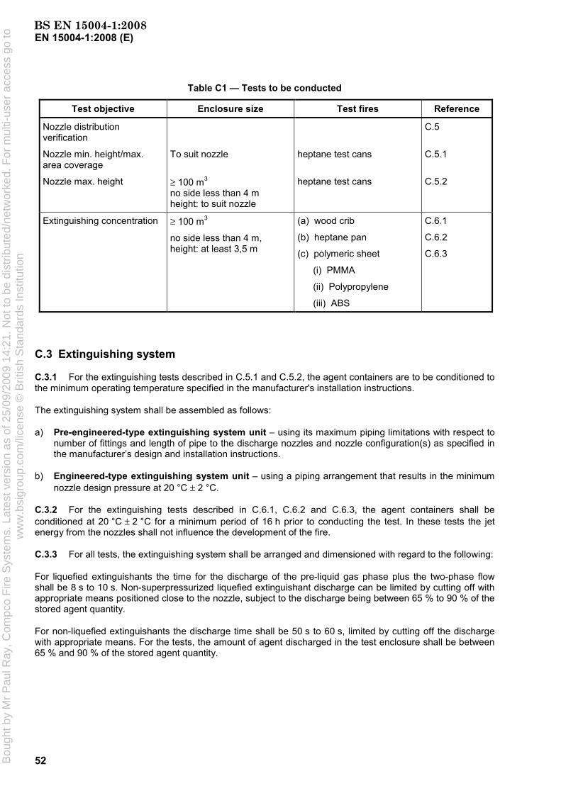
EN 15004-1:2008 (E)
52
Table C1 — Tests to be conducted
Test objective Enclosure size Test fires Reference
Nozzle distribution verification
Nozzle min. height/max. area coverage
Nozzle max. height
To suit nozzle
≥ 100 m3
no side less than 4 m height: to suit nozzle
heptane test cans
heptane test cans
C.5
C.5.1
C.5.2
Extinguishing concentration ≥ 100 m3
no side less than 4 m, height: at least 3,5 m
(a) wood crib
(b) heptane pan
(c) polymeric sheet
(i) PMMA
(ii) Polypropylene
(iii) ABS
C.6.1
C.6.2
C.6.3
C.3 Extinguishing system
C.3.1 For the extinguishing tests described in C.5.1 and C.5.2, the agent containers are to be conditioned to the minimum operating temperature specified in the manufacturer's installation instructions.
The extinguishing system shall be assembled as follows:
a) Pre-engineered-type extinguishing system unit – using its maximum piping limitations with respect to number of fittings and length of pipe to the discharge nozzles and nozzle configuration(s) as specified in the manufacturer’s design and installation instructions.
b) Engineered-type extinguishing system unit – using a piping arrangement that results in the minimum nozzle design pressure at 20 °C ± 2 °C.
C.3.2 For the extinguishing tests described in C.6.1, C.6.2 and C.6.3, the agent containers shall be conditioned at 20 °C ± 2 °C for a minimum period of 16 h prior to conducting the test. In these tests the jet energy from the nozzles shall not influence the development of the fire.
C.3.3 For all tests, the extinguishing system shall be arranged and dimensioned with regard to the following:
For liquefied extinguishants the time for the discharge of the pre-liquid gas phase plus the two-phase flow shall be 8 s to 10 s. Non-superpressurized liquefied extinguishant discharge can be limited by cutting off with appropriate means positioned close to the nozzle, subject to the discharge being between 65 % to 90 % of the stored agent quantity.
For non-liquefied extinguishants the discharge time shall be 50 s to 60 s, limited by cutting off the discharge with appropriate means. For the tests, the amount of agent discharged in the test enclosure shall be between 65 % and 90 % of the stored agent quantity.
BS EN 15004-1:2008B
ough
t by
Mr
Pau
l Ray
, Com
pco
Fire
Sys
tem
s. L
ates
t ver
sion
as
of 2
5/09
/200
9 14
:21.
Not
to b
e di
strib
uted
/net
wor
ked.
For
mul
ti-us
er a
cces
s go
tow
ww
.bsi
grou
p.co
m/li
cens
e ©
Brit
ish
Sta
ndar
ds In
stitu
tion

EN 15004-1:2008 (E)
53
C.4 Extinguishing concentration
C.4.1 The extinguishing agent for tests C.5.1, C.5.2, C.6.1, C.6.2 and C.6.3 shall be 76,9 % (i.e. 100/safety factor, where the safety factor is 1,3 of the intended minimum design concentration specified in the manufacturer's design and installation instructions at the ambient temperature of 20 °C ± 2 °C within the enclosure. In the tests described in C.5.1 and C.5.2, the same extinguishing concentration has to be used as in the tests described in section C.6.2.
The quantity to reach the concentration within the enclosure can be established using the Equation (1) and Equation (2) (in 7.6.2 and 7.6.3) for liquefied gases and non-liquefied gases respectively.
C.4.2 A cold discharge test using the same quantity (± 2 %) of extinguishant is to be conducted to verify the actual concentration of extinguishant.
For liquefied extinguishants, the agent concentration shall be measured in the cold discharge test.
For non-liquefied extinguishants, the agent concentration or alternatively the oxygen concentration shall be measured. The extinguishant concentration is then calculated from the oxygen concentration using the following formula:
−=95,20o1100E
CC (C.1)
where
cE is the extinguishant concentration, as a volume fraction in percent;
co is the oxygen concentration measured in the test enclosure, as a volume fraction in percent.
C.5 Nozzle distribution verification tests
C.5.1 Nozzles minimum height/maximum area coverage test
C.5.1.1 Test facility
C.5.1.1.1 Construction
The test enclosure shall meet the following requirements:
a) the area, a × b (see Figure C.1), and height, H, of the enclosure shall correspond to the maximum nozzle area coverage and minimum nozzle height specified by the manufacturer;
b) a means of pressure relief shall be provided;
c) closable openings shall be provided directly above the test cans to allow for venting prior to system actuation;
d) one baffle is to be installed between the floor and ceiling with the height of the room. It is to be installed halfway between the nozzle location and the walls of the enclosure (see Figure C.1 for 360° nozzle and Figure C.2 for 180° nozzle). The baffle is to be perpendicular to the direction between nozzle location and walls of the enclosure (see Figures C.1 and C.2), and be 20 % of the length of the short wall of the enclosure.
BS EN 15004-1:2008B
ough
t by
Mr
Pau
l Ray
, Com
pco
Fire
Sys
tem
s. L
ates
t ver
sion
as
of 2
5/09
/200
9 14
:21.
Not
to b
e di
strib
uted
/net
wor
ked.
For
mul
ti-us
er a
cces
s go
tow
ww
.bsi
grou
p.co
m/li
cens
e ©
Brit
ish
Sta
ndar
ds In
stitu
tion

EN 15004-1:2008 (E)
54
Key (see Figure C.2)
Figure C.1 —Example configuration for nozzle minimum height/maximum area coverage test for 360° nozzles
Key
1 test cans 3 baffle 2 nozzle 4 vents a × b = maximum nozzle area coverage for a single nozzle
Figure C.2 —Example configuration for nozzle minimum height/maximum area coverage test for 180° nozzles
BS EN 15004-1:2008B
ough
t by
Mr
Pau
l Ray
, Com
pco
Fire
Sys
tem
s. L
ates
t ver
sion
as
of 2
5/09
/200
9 14
:21.
Not
to b
e di
strib
uted
/net
wor
ked.
For
mul
ti-us
er a
cces
s go
tow
ww
.bsi
grou
p.co
m/li
cens
e ©
Brit
ish
Sta
ndar
ds In
stitu
tion

EN 15004-1:2008 (E)
55
C.5.1.1.2 Instrumentation
C.5.1.1.2.1 Recording of data
Sampling and storage of data from the sensors described below shall occur at a rate of at least 10 Hz.
C.5.1.1.2.2 Oxygen concentrations
The oxygen concentration shall be measured using a calibrated oxygen analyser having an accuracy not less than 0,1 %. The sensing equipment shall be capable of continuously monitoring and recording the oxygen level inside the enclosure throughout the duration of the test. The accuracy of the measuring devices shall not be influenced by any of the fire products.
At least three sensors shall be located within the enclosure (see Figures C.3 and C.4). The three sensors shall be located in a horizontal distance from the centre of the room 850 mm to 1 250 mm and in the following heights: 0,1 H, 0,5 H and 0,9 H (H = height of the enclosure) above the floor.
The location of the sensors in a test room with room height less than 0,6 m can be placed in three perpendicular axes.
C.5.1.1.2.3 Nozzle pressure
The nozzle pressure during system discharge shall be recorded by a pressure transducer in the pipe work at a distance not greater than 1 m from the nozzle.
C.5.1.1.2.4 Enclosure temperature
The temperature in the enclosure shall be measured and recorded. The location of the measurement shall be at one-half the room height and at a horizontal position of 850 mm to 1 250 mm from the centre of the floor. See Figures C.3 and C.4.
C.5.1.1.2.5 Nozzle temperature
For liquefied extinguishants, the temperature of the liquid jet just outside the nozzle shall be recorded.
A thermocouple can be located centrally 30 mm above each fire test can as additional information.
C.5.1.2 Fuel specification
C.5.1.2.1 Test cans
The test cans are to be cylindrical 80 mm ± 5 mm in diameter and at least 100 mm high, made of mild or stainless steel with a thickness of 5 mm to 6 mm.
C.5.1.2.2 Heptane specification
The heptane used shall have the following characteristics:
a) distillation:
1) initial boiling point: 90 °C minimum;
2) dry point: 100 °C maximum;
b) density (at 15,6 °C): 700 ± 50 kg/m3.
BS EN 15004-1:2008B
ough
t by
Mr
Pau
l Ray
, Com
pco
Fire
Sys
tem
s. L
ates
t ver
sion
as
of 2
5/09
/200
9 14
:21.
Not
to b
e di
strib
uted
/net
wor
ked.
For
mul
ti-us
er a
cces
s go
tow
ww
.bsi
grou
p.co
m/li
cens
e ©
Brit
ish
Sta
ndar
ds In
stitu
tion

EN 15004-1:2008 (E)
56
Dimensions in millimetres
NOTE Room height H < 0,6 m, measuring points (M1 to M3) in two or three axes.
Figure C.3 — Plan view instrumentation placement for nozzle minimum height/maximum area coverage test
C.5.1.2.3 Fuel-test can configuration
The test cans may contain either heptane or heptane on water. If they are to contain heptane and water, the heptane is to be at least 50 mm deep. The level of heptane in the cans shall be at least 50 mm below the top of the can.
C.5.1.2.4 Test can placement
A test can shall be placed in each corner of the enclosure within 50 mm of the corners of the enclosure wall. In addition, one of two test cans, depending on enclosure height, is to be placed directly behind the baffle (see Figures C.1 and C.2). Test cans are to be positioned within 300 mm of the top or bottom of the enclosure, or both top and bottom if the enclosure permits such placement.
C.5.1.3 Test procedure
C.5.1.3.1 Agent certification
The composition of the extinguishing agent used shall be verified by certificate of conformance or by test.
BS EN 15004-1:2008B
ough
t by
Mr
Pau
l Ray
, Com
pco
Fire
Sys
tem
s. L
ates
t ver
sion
as
of 2
5/09
/200
9 14
:21.
Not
to b
e di
strib
uted
/net
wor
ked.
For
mul
ti-us
er a
cces
s go
tow
ww
.bsi
grou
p.co
m/li
cens
e ©
Brit
ish
Sta
ndar
ds In
stitu
tion

EN 15004-1:2008 (E)
57
Dimensions in millimetres
NOTE Room height H < 0,6 m, measuring points (M1 to M3) in two or three axes.
Figure C.4 — Side view instrumentation placement for nozzle minimum height/maximum area coverage test
C.5.1.3.2 Operation
The heptane-filled test cans shall be ignited and allowed to burn for 30 s with the closable openings above in the open position.
After 30 s all openings shall be closed and the extinguishing system shall be manually actuated. At the time of actuation of the system, the amount of oxygen within the enclosure shall not be more than 0,5 % (volume fraction) lower than the normal atmospheric oxygen concentration. During the test, the oxygen concentration shall not change more than 1,5 % (volume fraction) due to fire products. This change shall be determined by comparing the oxygen concentration measured in the cold discharge test with the measured oxygen concentration in this test (averaged over the three sensors).
NOTE End of discharge is the point when discharge has effectively ceased. For superpressurized liquefied extinguishants it is the instant when the discharge is predominantly gaseous. For non-superpressurized liquefied extinguishants and non-liquefied extinguishants where a cut-off mechanism is used to stop discharge, it is the instant when the pressure at the nozzle reduces to zero.
C.5.1.4 Recording of results
After the required pre-burn period, record the following data for each test:
a) the effective discharge time, i.e. for liquefied extinguishants the time of the pre-liquid gas phase plus the time of the two phase flow; for non-liquefied extinguishants the time from opening the container valve(s)
BS EN 15004-1:2008B
ough
t by
Mr
Pau
l Ray
, Com
pco
Fire
Sys
tem
s. L
ates
t ver
sion
as
of 2
5/09
/200
9 14
:21.
Not
to b
e di
strib
uted
/net
wor
ked.
For
mul
ti-us
er a
cces
s go
tow
ww
.bsi
grou
p.co
m/li
cens
e ©
Brit
ish
Sta
ndar
ds In
stitu
tion

EN 15004-1:2008 (E)
58
to cutting off the discharge. The discharge time for liquefied extinguishants has to be determined by nozzle pressure, nozzle temperature or combination of both;
b) the time required to achieve extinguishment, in seconds. This time shall be determined by visual observation or other suitable means;
c) the total mass of extinguishant discharged into the test enclosure.
C.5.1.5 Determination of distribution performance of the nozzle
All test cans have to be extinguished within 30 s after the end of agent discharge.
As an alternate to the use of the heptane steel cans, the concentration of the extinguishing agent (or for non-liquefied gases: the oxygen concentration) can be measured at the locations specified for the steel test cans. The concentration shall be measured at each location and shall be at least the extinguishing concentration, to be reached 30 s after end of discharge time at latest.
C.5.2 Nozzles maximum height test
C.5.2.1 Test facility
C.5.2.1.1 Construction
The test enclosure shall meet the following requirements:
a) the test enclosure shall have a minimum volume of 100 m3. The floor dimensions shall be at least 4 m wide by 4 m long. The test enclosure is to have the maximum ceiling height as specified in the manufacturer's installation instructions;
b) a means of pressure relief shall be provided;
c) closable openings shall be provided directly above the test cans to allow for venting prior to system actuation;
d) one baffle is to be installed between the floor and ceiling with the height of the room. It is to be installed halfway between the nozzle location and the walls of the enclosure (see Figure C.1 for 360° nozzle and Figure C.2 for 180° nozzle). The baffle is to be perpendicular to the direction of nozzle discharge, and be 20 % of the length of the short wall of the enclosure.
C.5.2.1.2 Instrumentation
Instrumentation of the enclosure is as described in C.5.1.1.2.
C.5.2.2 Fuel specification
Test fire can construction, configuration, placement and fuel specifications shall be as given in C.5.1.2.
C.5.2.3 Test procedure
C.5.2.3.1 Agent certification
The composition of the extinguishing agent used shall be verified by certificate of conformance or by test.
BS EN 15004-1:2008B
ough
t by
Mr
Pau
l Ray
, Com
pco
Fire
Sys
tem
s. L
ates
t ver
sion
as
of 2
5/09
/200
9 14
:21.
Not
to b
e di
strib
uted
/net
wor
ked.
For
mul
ti-us
er a
cces
s go
tow
ww
.bsi
grou
p.co
m/li
cens
e ©
Brit
ish
Sta
ndar
ds In
stitu
tion

EN 15004-1:2008 (E)
59
C.5.2.3.2 Operation
The heptane is to be ignited and allowed to burn for 30 s with the closable openings above in the open position.
After 30 s all openings shall be closed and the extinguishing system shall be manually actuated. At the time of actuation of the system, the amount of oxygen within the enclosure shall not be more than 0,5 % (volume fraction) lower than the normal atmospheric oxygen concentration. During the test, the oxygen concentration shall not change more than 1,5 % (volume fraction) due to fire products. This change shall be determined by comparing the oxygen concentration measured in the cold discharge test with the oxygen concentration measured in this fire test (averaged values).
C.5.2.3.3 Recording of results
Results are to be recorded as specified in C.5.1.4.
C.5.2.4 Determination of distribution performance of the nozzle
Using the extinguishing concentration for heptane, determined in accordance with C.6.2, all test cans have to be extinguished within 30 s after the end of agent discharge.
As an alternate to the use of the heptane steel cans, the concentration of the extinguishing agent (or for non-liquefied gases: the oxygen concentration) can be measured at the locations specified for the steel test cans. The concentration shall be measured at each location and shall be at least the extinguishing concentration, to be reached 30 s after the end of discharge time at latest.
C.6 Extinguishing concentration tests
C.6.1 Wood crib test
C.6.1.1 Test facility
C.6.1.1.1 Construction
The test enclosure shall meet the following requirements:
a) the test enclosure shall have a minimum volume of 100 m3. The height shall be at least 3,5 m. The floor dimensions shall be at least 4 m wide by 4 m long;
b) a means of pressure relief shall be provided;
c) the temperature in the test enclosure shall be 20 °C ± 5 °C at the beginning of each test and there shall be enough time between tests so that the enclosure can adapt to this temperature.
C.6.1.1.2 Instrumentation
Sampling and storage of data from the sensors described below shall occur at a rate of at least 10 Hz.
C.6.1.1.3 Oxygen concentrations
The oxygen concentration shall be measured by a calibrated oxygen analyser having an accuracy not less than 0,1 %. The sensing equipment shall be capable of continuously monitoring and recording the oxygen level inside the enclosure throughout the duration of the test. The accuracy of the measuring devices shall not be influenced by any of the fire products.
BS EN 15004-1:2008B
ough
t by
Mr
Pau
l Ray
, Com
pco
Fire
Sys
tem
s. L
ates
t ver
sion
as
of 2
5/09
/200
9 14
:21.
Not
to b
e di
strib
uted
/net
wor
ked.
For
mul
ti-us
er a
cces
s go
tow
ww
.bsi
grou
p.co
m/li
cens
e ©
Brit
ish
Sta
ndar
ds In
stitu
tion
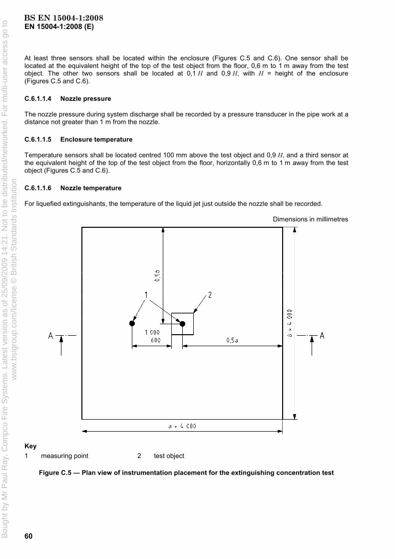
EN 15004-1:2008 (E)
60
At least three sensors shall be located within the enclosure (Figures C.5 and C.6). One sensor shall be located at the equivalent height of the top of the test object from the floor, 0,6 m to 1 m away from the test object. The other two sensors shall be located at 0,1 H and 0,9 H, with H = height of the enclosure (Figures C.5 and C.6).
C.6.1.1.4 Nozzle pressure
The nozzle pressure during system discharge shall be recorded by a pressure transducer in the pipe work at a distance not greater than 1 m from the nozzle.
C.6.1.1.5 Enclosure temperature
Temperature sensors shall be located centred 100 mm above the test object and 0,9 H, and a third sensor at the equivalent height of the top of the test object from the floor, horizontally 0,6 m to 1 m away from the test object (Figures C.5 and C.6).
C.6.1.1.6 Nozzle temperature
For liquefied extinguishants, the temperature of the liquid jet just outside the nozzle shall be recorded.
Dimensions in millimetres
Key 1 measuring point 2 test object
Figure C.5 — Plan view of instrumentation placement for the extinguishing concentration test
BS EN 15004-1:2008B
ough
t by
Mr
Pau
l Ray
, Com
pco
Fire
Sys
tem
s. L
ates
t ver
sion
as
of 2
5/09
/200
9 14
:21.
Not
to b
e di
strib
uted
/net
wor
ked.
For
mul
ti-us
er a
cces
s go
tow
ww
.bsi
grou
p.co
m/li
cens
e ©
Brit
ish
Sta
ndar
ds In
stitu
tion

EN 15004-1:2008 (E)
61
Dimensions in millimetres
Key 1 test object M1 to M5 measuring points
Figure C.6 — Side view of instrumentation placement for the extinguishing concentration test
C.6.1.2 Fuel specification
C.6.1.2.1 Crib igniter fuel
Ignition of the crib is achieved by burning 1,5 l of heptane (specified in C.5.1.2.2) on a 12,5 l layer of water in a square steel pan 0,25 m2 in area, 100 mm in height and with a wall thickness of 6 mm (see Figure C.7).
C.6.1.2.2 Fire configuration and placement
The wood crib is to consist of four layers of six, approximately 40 mm × 40 mm by 450 mm ± 50 mm long, kiln spruce or fir lumber having a moisture content between 9 % and 13 %. Place the alternate layers of wood members at right angles to one another. Evenly space the individual wood members in each layer forming a square determined by the specified length of the wood members. Staple or nail together the wood members forming the outside edges of the crib.
The crib shall be preburned on a stand supporting the crib. The distance from the bottom of the crib to the top of the pan holding the igniter fuel (specified in C.6.1.2.1) shall be 300 mm. The bottom of the crib shall be 600 mm above the floor.
BS EN 15004-1:2008B
ough
t by
Mr
Pau
l Ray
, Com
pco
Fire
Sys
tem
s. L
ates
t ver
sion
as
of 2
5/09
/200
9 14
:21.
Not
to b
e di
strib
uted
/net
wor
ked.
For
mul
ti-us
er a
cces
s go
tow
ww
.bsi
grou
p.co
m/li
cens
e ©
Brit
ish
Sta
ndar
ds In
stitu
tion
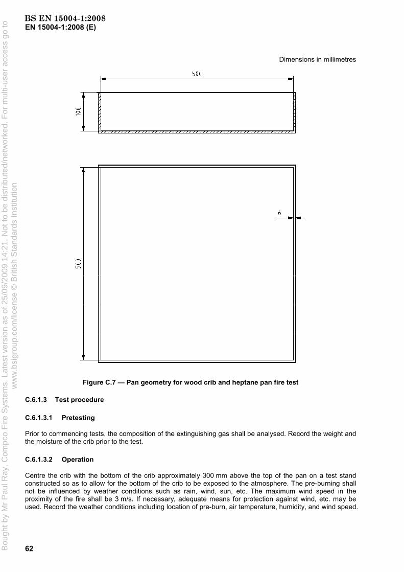
EN 15004-1:2008 (E)
62
Dimensions in millimetres
Figure C.7 — Pan geometry for wood crib and heptane pan fire test
C.6.1.3 Test procedure
C.6.1.3.1 Pretesting
Prior to commencing tests, the composition of the extinguishing gas shall be analysed. Record the weight and the moisture of the crib prior to the test.
C.6.1.3.2 Operation
Centre the crib with the bottom of the crib approximately 300 mm above the top of the pan on a test stand constructed so as to allow for the bottom of the crib to be exposed to the atmosphere. The pre-burning shall not be influenced by weather conditions such as rain, wind, sun, etc. The maximum wind speed in the proximity of the fire shall be 3 m/s. If necessary, adequate means for protection against wind, etc. may be used. Record the weather conditions including location of pre-burn, air temperature, humidity, and wind speed.
BS EN 15004-1:2008B
ough
t by
Mr
Pau
l Ray
, Com
pco
Fire
Sys
tem
s. L
ates
t ver
sion
as
of 2
5/09
/200
9 14
:21.
Not
to b
e di
strib
uted
/net
wor
ked.
For
mul
ti-us
er a
cces
s go
tow
ww
.bsi
grou
p.co
m/li
cens
e ©
Brit
ish
Sta
ndar
ds In
stitu
tion

EN 15004-1:2008 (E)
63
Ignite the heptane and allow the crib to burn freely. The crib shall be allowed to burn freely for a total pre-burn time of 6 min 10
0+ s.
At the time of actuation of the system, the amount of oxygen within the enclosure at the level of the crib shall not be more than 0,5 % (volume fraction) lower than the normal atmospheric oxygen concentration. During the test, the oxygen concentration shall not change more than 1,5 % (volume fraction) due to fire products. This change shall be determined by comparing the oxygen concentration measured in the cold discharge test with the oxygen concentration measured in this fire test (averaged values). If the start oxygen concentration in the fire tests and the cold discharge test are different, this has to be taken into account while comparing the oxygen concentrations.
From the end of system discharge, the enclosure is to remain sealed for a total of 10 min. After the soak period, remove the crib from the enclosure and observe to determine that sufficient fuel remains to sustain combustion and for signs of re-ignition. The following shall be recorded:
a) presence and location of burning embers;
b) whether or not the glowing embers or crib re-ignite;
c) weight of the crib after the test.
If necessary, amend the extinguishant concentration and repeat the experimental programme until three successive, successful extinguishments are achieved.
C.6.1.3.3 Results recording
After the required pre-burn period, record the following data for each test:
a) the effective discharge time, i.e. for liquefied extinguishants the time of the pre-liquid gas phase plus the time of the two phase flow; for non-liquefied extinguishants the time from opening the container valve(s) to cutting off the discharge. The discharge time for liquefied extinguishants has to be determined by nozzle pressure, nozzle temperature or combination of both;
b) the time required to achieve extinguishment, in seconds. This time shall be determined by visual observation or other suitable means;
c) the total mass of extinguishant discharged into the test enclosure;
d) the soaking time (time from the end of system discharge until the opening of the test enclosure);
e) the temperature profile of the wood crib.
NOTE End of discharge is the point when discharge has effectively ceased. For superpressurized liquefied extinguishants it is the instant when the discharge is predominantly gaseous. For non-superpressurized liquefied extinguishants and non-liquefied extinguishants where a cut-off mechanism is used to stop discharge, it is the instant when the pressure at the nozzle reduces to zero.
C.6.1.4 Determination of design extinguishant concentration
The laboratory extinguishant concentration is that concentration which achieves satisfactory extinguishment of the fire over three successive tests (no re-ignition or existence of burning embers after 10 min after end of discharge). Alternatively, three successful, non-successive tests may be used providing the highest concentration is taken (i.e. the test with the greatest mass of agent discharged and the longest discharge time). The design concentration is the laboratory concentration multiplied by an appropriate 'safety factor’.
BS EN 15004-1:2008B
ough
t by
Mr
Pau
l Ray
, Com
pco
Fire
Sys
tem
s. L
ates
t ver
sion
as
of 2
5/09
/200
9 14
:21.
Not
to b
e di
strib
uted
/net
wor
ked.
For
mul
ti-us
er a
cces
s go
tow
ww
.bsi
grou
p.co
m/li
cens
e ©
Brit
ish
Sta
ndar
ds In
stitu
tion

EN 15004-1:2008 (E)
64
C.6.2 Heptane pan test
C.6.2.1 Test facility
C.6.2.1.1 Construction
Construction of the enclosure is as described in C.6.1.1.1.
C.6.2.1.2 Instrumentation
Instrumentation of the enclosure is as described in C.6.1.1.2 to C.6.1.1.6.
C.6.2.2 Fuel specification
C.6.2.2.1 Heptane
The heptane is as specified in C 5.1.2.2.
C.6.2.2.2 Fire configuration and placement
The fire shall be in a square steel pan of 0,25 m2, 100 mm high with a wall thickness of 6 mm as specified in C.6.1.2.1. The test pan is to contain 12,5 l of heptane. The resulting heptane surface is then 50 mm below the top of the pan.
The steel pan shall be located in the centre of the test enclosure with the bottom 600 mm above the floor of the test enclosure.
C.6.2.3 Test procedure
C.6.2.3.1 Pretesting
Prior to commencing tests, the composition of the extinguishing gas shall be determined by analysis.
C.6.2.3.2 Operation
The heptane shall be ignited and allowed to burn for 30 s.
After 30 s all openings shall be closed and the extinguishing system shall be manually actuated. At the time of actuation of the system, the amount of oxygen within the enclosure shall not be more than 0,5 % (volume fraction) lower than the normal atmospheric oxygen concentration. During the test, the oxygen concentration shall not change more than 1,5 % (volume fraction) due to fire products. This change shall be determined by comparing the oxygen concentration measured in the cold discharge test with the oxygen concentration measured in this fire test (averaged values).
If necessary, amend the extinguishant concentration and repeat the experimental programme until three successive, successful extinguishments are achieved.
C.6.2.3.3 Agent certification
The composition of the extinguishing agent shall be verified by a certificate of conformance or by test.
C.6.2.3.4 Recording of results
Results are to be recorded as specified in C.6.1.3.3 with the exception of e).
BS EN 15004-1:2008B
ough
t by
Mr
Pau
l Ray
, Com
pco
Fire
Sys
tem
s. L
ates
t ver
sion
as
of 2
5/09
/200
9 14
:21.
Not
to b
e di
strib
uted
/net
wor
ked.
For
mul
ti-us
er a
cces
s go
tow
ww
.bsi
grou
p.co
m/li
cens
e ©
Brit
ish
Sta
ndar
ds In
stitu
tion

EN 15004-1:2008 (E)
65
C.6.2.4 Determination of design extinguishant concentration
The laboratory extinguishant concentration is that concentration which achieves satisfactory extinguishment of the fire over three successive tests (no flaming 30 s after the end of extinguishant discharge). Alternatively, three successful, non-successive tests may be used providing the highest concentration is taken (that is, the test with the greatest mass of agent discharged and the longest discharge time). The design concentration is the laboratory concentration multiplied by an appropriate 'safety factor'.
C.6.3 Polymeric sheet fire test
C.6.3.1 Test facility
C.6.3.1.1 Construction
Construction of the enclosure is as described in C.5.1.1.1.
C.6.3.1.2 Instrumentation
Instrumentation of the enclosure is as described in C.5.1.1.2 to C.6.1.1.6.
C.6.3.2 Fuel specification
C.6.3.2.1 Igniter fuel
The ignition source is a heptane pan (constructed of 2 mm thick mild or stainless steel), internal dimensions of 51 mm x 112 mm and 21 mm deep, and centred 12 mm below the bottom of the plastic sheets (see Figure C.8). The 51 mm side of the pan is oriented parallel to the sheets of polymeric fuel. The pan is filled with 6 ml of commercial grade heptane (specified in C.5.1.2.2) on a water base of 40 ml.
C.6.3.2.2 Polymeric fuel
Tests are to be conducted with three plastic fuels:
polymethylmethacrylate (PMMA);
polypropylene (PP);
acrylonitrile-butadiene-styrene polymer (ABS).
Plastic properties are given in Table C.2.
Table C.2 — Plastic properties
Ignition Time 180 s average heat release rate
Effective heat of combustion
Fuel Colour Density
g/cm3 sec Tolerance kW/m2 Tolerance MJ/kg Tolerance
PMMA Black 1,19 77 30 % 286 25 % 23,3 25 %
PP Natural (White) 0,905 91 30 % 225 25 % 39,6 25 %
ABS Natural (Cream) 1,04 115 30 % 484 25 % 29,1 25 %
NOTE 25 kW/m2 exposure in Cone Calorimeter – ISO 5660-1 [1].
BS EN 15004-1:2008B
ough
t by
Mr
Pau
l Ray
, Com
pco
Fire
Sys
tem
s. L
ates
t ver
sion
as
of 2
5/09
/200
9 14
:21.
Not
to b
e di
strib
uted
/net
wor
ked.
For
mul
ti-us
er a
cces
s go
tow
ww
.bsi
grou
p.co
m/li
cens
e ©
Brit
ish
Sta
ndar
ds In
stitu
tion

EN 15004-1:2008 (E)
66
C.6.3.2.3 Polymeric fuel array
The polymeric fuel array consists of 4 sheets of polymer, which are cut to 405 mm ± 5 mm high by 200 mm ± 5 mm wide. The thickness of the sheets shall be as follows:
polymethylmethacrylate (PMMA): (10 mm ± 1 mm);
polypropylene (PP): (10 mm ± 1 mm);
acrylonitrile-butadiene-styrene polymer (ABS): (10 mm ± 1 mm).
Sheets are spaced and located as shown in Figures C.8 and C.9. The bottom of the fuel array is located 43 mm from the floor. The fuel sheets shall be mechanically fixed at the required spacing. The sheets of plastic shall not significantly bend during the test.
The fuel array shall be located centrally within the enclosure.
C.6.3.2.4 Fuel shield
A fuel shield consisting of a metal frame with sheet metal on the top and two sides shall be provided around the fuel array as indicated in Figures C.8 and C.9. The fuel shield is 380 mm wide, 850 mm high and 610 mm deep. The 610 mm (wide) × 850 mm (high) sides and the 610 mm × 380 mm top are metal sheet. The two remaining sides and bottom are open.
The metal sheet shall have a wall thickness of 2 mm to 3 mm.
The fuel array is oriented in the fuel shield such that the 200 mm dimension of the fuel array is parallel to the 610 mm side of the fuel shield.
BS EN 15004-1:2008B
ough
t by
Mr
Pau
l Ray
, Com
pco
Fire
Sys
tem
s. L
ates
t ver
sion
as
of 2
5/09
/200
9 14
:21.
Not
to b
e di
strib
uted
/net
wor
ked.
For
mul
ti-us
er a
cces
s go
tow
ww
.bsi
grou
p.co
m/li
cens
e ©
Brit
ish
Sta
ndar
ds In
stitu
tion

EN 15004-1:2008 (E)
67
Dimensions in millimetres
Key 1 vertical metal angle frame 2 fuel guide bars (angle form) 3 fuel guide bar (U-form) 4 heptane pan 5 channel metal frame covered with metal sheeting on top and two sides 6 drip tray
Figure C.8 — Polymeric sheet fire
BS EN 15004-1:2008B
ough
t by
Mr
Pau
l Ray
, Com
pco
Fire
Sys
tem
s. L
ates
t ver
sion
as
of 2
5/09
/200
9 14
:21.
Not
to b
e di
strib
uted
/net
wor
ked.
For
mul
ti-us
er a
cces
s go
tow
ww
.bsi
grou
p.co
m/li
cens
e ©
Brit
ish
Sta
ndar
ds In
stitu
tion
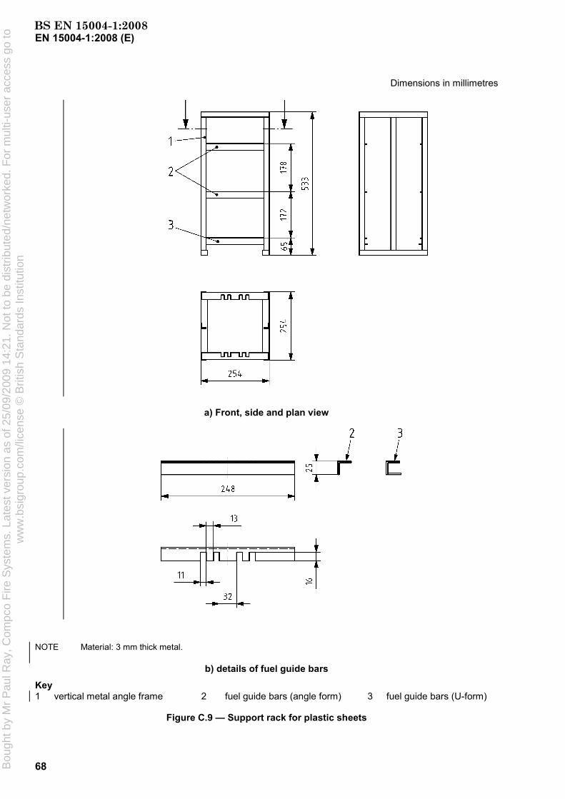
EN 15004-1:2008 (E)
68
Dimensions in millimetres
a) Front, side and plan view
NOTE Material: 3 mm thick metal.
b) details of fuel guide bars
Key 1 vertical metal angle frame 2 fuel guide bars (angle form) 3 fuel guide bars (U-form)
Figure C.9 — Support rack for plastic sheets
BS EN 15004-1:2008B
ough
t by
Mr
Pau
l Ray
, Com
pco
Fire
Sys
tem
s. L
ates
t ver
sion
as
of 2
5/09
/200
9 14
:21.
Not
to b
e di
strib
uted
/net
wor
ked.
For
mul
ti-us
er a
cces
s go
tow
ww
.bsi
grou
p.co
m/li
cens
e ©
Brit
ish
Sta
ndar
ds In
stitu
tion

EN 15004-1:2008 (E)
69
C.6.3.2.5 External baffles
External baffles are constructed as shown in Figure C.10 and are located around the exterior of the fuel shield. The baffles are placed 90 mm above the floor. The top baffle is rotated 45° with respect to the bottom baffle.
Dimensions in millimetres
Key 1 polycarbonate or metal baffles 2 cinder block
Figure C.10 — Polymeric fire baffle arrangement
C.6.3.3 Test procedure
C.6.3.3.1 Pretesting
Prior to commencing tests, the composition of the extinguishing gas shall be determined by analysis. Record the weight of the plastic sheets prior to the test.
BS EN 15004-1:2008B
ough
t by
Mr
Pau
l Ray
, Com
pco
Fire
Sys
tem
s. L
ates
t ver
sion
as
of 2
5/09
/200
9 14
:21.
Not
to b
e di
strib
uted
/net
wor
ked.
For
mul
ti-us
er a
cces
s go
tow
ww
.bsi
grou
p.co
m/li
cens
e ©
Brit
ish
Sta
ndar
ds In
stitu
tion

EN 15004-1:2008 (E)
70
C.6.3.3.2 Operation
The heptane shall be ignited and allowed to burn completely. 210 s after ignition of the heptane, all openings shall be closed and the extinguishing system shall be manually actuated.
At the time of actuation of the system, the amount of oxygen within the enclosure at the level of the fuel shall not be more than 0,5 % (volume fraction) lower than the normal atmospheric oxygen concentration. During the test, the oxygen concentration shall not change more than 1,5 % (volume fraction) due to fire products. This change shall be determined by comparing the oxygen concentration measured in the cold discharge test with the oxygen concentration measured in this fire test (averaged values).
The enclosure shall remain sealed for a total of 10 min from the end of discharge. After the soak period, ventilate the enclosure and observe to determine that sufficient fuel remains to sustain combustion and for signs of re-ignition. The following shall be recorded:
a) presence and location of burning fuel;
b) whether or not the fire re-ignites;
c) weight of the fire structure after the test.
If necessary, amend the extinguishant concentration and repeat the experimental programme until 3 successive, successful extinguishments are achieved.
C.6.3.3.3 Recording of results
After the required pre-burn period, record the following data for each test:
a) the effective discharge time, i.e. for liquefied extinguishants the time of the pre-liquid gas phase plus the time of the two-phase flow; for non-liquefied extinguishants the time from opening the container valve(s) to cutting off the discharge; the discharge time for liquefied extinguishants has to be determined by nozzle pressure, nozzle temperature or combination of both;
b) the time to achieve “knock-down” of the flames, that means the time when there are only flames at the top edges of the two inner plastic sheets, in seconds; this time shall be determined by visual observation or other suitable means;
c) the time required to achieve extinguishment, in seconds; this time shall be determined by visual observation or other suitable means;
d) the total mass of extinguishant discharged into the test enclosure;
e) The soaking time (time from the end of system discharge until the opening of the test enclosure).
NOTE End of discharge is the point when discharge has effectively ceased. For superpressurized liquefied extinguishants it is the instant when the discharge is predominantly gaseous. For non-superpressurized liquefied extinguishants and non-liquefied extinguishants where a cut-off mechanism is used to stop discharge, it is the instant when the pressure at the nozzle reduces to zero.
C.6.3.4 Determination of design extinguishant concentration
The extinguishing concentration for each fuel is that concentration which achieves satisfactory extinguishment of the fire over three successive tests (only flames at the top edges of the 2 inner plastic sheets at 60 s after end of discharge, no flaming 180 s after end of discharge and no re-ignition after 10 min from end of discharge). Alternatively, three successful, non-successive tests may be used providing the highest concentration is taken (that is, the test with the greatest mass of agent discharged and the longest discharge time).
The minimum design concentration is the highest of the laboratory concentrations for the three fuels (see C 6.3.2.2) multiplied by an appropriate 'safety factor’.
BS EN 15004-1:2008B
ough
t by
Mr
Pau
l Ray
, Com
pco
Fire
Sys
tem
s. L
ates
t ver
sion
as
of 2
5/09
/200
9 14
:21.
Not
to b
e di
strib
uted
/net
wor
ked.
For
mul
ti-us
er a
cces
s go
tow
ww
.bsi
grou
p.co
m/li
cens
e ©
Brit
ish
Sta
ndar
ds In
stitu
tion

EN 15004-1:2008 (E)
71
Annex D (normative)
Method of evaluating inerting concentration of a fire extinguishant
D.1 General
This Annex specifies a method for determining the inerting or inhibiting concentration of the extinguishant based on flammability diagram data on ternary systems (fuel, extinguishant, air).
D.2 Principle
Fuel/extinguishant/air mixture at a pressure of 1 atm (1 bar or 14,7 psia) is ignited using a gap spark and the rise in pressure is measured.
D.3 Apparatus
D.3.1 Test vessel, spherical, with a capacity of 7,9 l ± 0,25 l, with inlet and vent ports, thermocouple and pressure transducer, as shown in Figure D.1.
D.3.2 Igniter, for nominal resistance of 1 Ω comprising four graphite rods ("H" pencil leads) held together by two wire ties at either end, leaving a gap between the ties of approximately 3 mm.
D.3.3 Capacitors, two 525 mF, 450 V, wired in series with the igniter.
D.3.4 Internal mixing fan, suitable to withstand the temperature and overpressure of an explosion.
D.4 Procedure
D.4.1 The sphere (D.3.1) and components should be at nominal room temperature (22 °C ± 3 °C). Note any temperature difference outside of this range.
D.4.2 Connect the pressure transducer to a suitable recording device to measure the pressure rise in the test vessel to the nearest 70 Pa.
D.4.3 Evacuate the test vessel (D.3.1).
D.4.4 Admit the extinguishant up to the concentration required by the partial pressure method and, if a liquid, allow time for evaporation to occur.
D.4.5 Admit fuel vapour and air [(50 ± 5) % relative humidity] up to the concentration required by the partial pressure method until the pressure in the vessel is 1 atm (1 bar or 14,7 psia).
D.4.6 Turn on the fan (D.3.4) and allow to mix for 1 min. Turn off the fan and wait for 1 min for the mixture to reach quiescent conditions.
D.4.7 Charge the capacitors (D.3.3) to a potential of 720 V to 740 V (DC), producing a stored energy of 68 J to 70 J.
BS EN 15004-1:2008B
ough
t by
Mr
Pau
l Ray
, Com
pco
Fire
Sys
tem
s. L
ates
t ver
sion
as
of 2
5/09
/200
9 14
:21.
Not
to b
e di
strib
uted
/net
wor
ked.
For
mul
ti-us
er a
cces
s go
tow
ww
.bsi
grou
p.co
m/li
cens
e ©
Brit
ish
Sta
ndar
ds In
stitu
tion

EN 15004-1:2008 (E)
72
D.4.8 Close the switch and discharge the capacitors.
NOTE The capacitor discharge current results in ionization of the graphite rod surface causing a corona spark to jump across the connector gap.
D.4.9 Measure and record the pressure rise, if any.
D.4.10 Clean the inside of the test vessel with distilled water and cloths to avoid any build up of decomposition residues.
D.4.11 Retain the fuel/air ratio and repeat the test using varying amounts of extinguishant until conditions are found that bracket a pressure rise of 0,07 times the initial pressure.
NOTE The definition of the flammable boundary is taken as that composition that just produces a pressure rise of 0,07 times the initial pressure or 1 psi when the initial pressure is 1 atm (1 bar or 14,7 psia).
D.4.12 Repeat, varying the fuel/air ratio and the extinguishant concentration to establish the highest extinguishant concentration needed to inert the mixture.
D.5 Inerting concentration
The inerting concentration is the concentration established in step D.4.12.
Key
1 septum port 2 gas inlet 3 7,9 l test vessel 4 igniter 5 vent
6 vacuum 7 pressure gauge 8 thermocouple 9 test chamber
Figure D.1 — Inerting apparatus
BS EN 15004-1:2008B
ough
t by
Mr
Pau
l Ray
, Com
pco
Fire
Sys
tem
s. L
ates
t ver
sion
as
of 2
5/09
/200
9 14
:21.
Not
to b
e di
strib
uted
/net
wor
ked.
For
mul
ti-us
er a
cces
s go
tow
ww
.bsi
grou
p.co
m/li
cens
e ©
Brit
ish
Sta
ndar
ds In
stitu
tion

EN 15004-1:2008 (E)
73
Annex E (normative)
Door fan test for determination of minimum hold time
E.1 General
This Annex contains information to establish the integrity of rooms and enclosures with respect to maintaining the extinguishant concentration for the relevant period (hold time). It includes details of testing and assumes that air-handling plant will not be operating during the hold time.
This procedure cannot be used to predict what extinguishant concentrations may develop in adjoining spaces.
This procedure is only suitable providing:
a) an adequate return air path exists (see E.2.4.2 and E.2.7.1.3);
b) the fan unit(s) can develop an enclosure pressure of 25 Pa (this is a function of the size of the enclosure, its integrity, and the number and capacities of the fans (see E.2.2.1 and E.2.7.4.3).
The calculation procedures used are suitable for both heavier than air extinguishants and extinguishants that are lighter than air. The hold time calculation models, for enclosures without continuous mixing, assume that the enclosure is either a standard enclosure or a non standard enclosure. A standard enclosure is one that has a uniform horizontal cross sectional area with horizontal upper and lower boundaries. A non-standard enclosure is one with a non uniform horizontal cross sectional area and/or sloping upper and/or lower boundaries.
NOTE For gas/air mixtures heavier than air, the calculation procedures have been verified by comparison of calculation results from door fan testing with hold times from real flooding tests. This has not yet been done for gas mixtures lighter than air.
E.2 Test for determination of predicted hold time
E.2.1 Principle
A fan is temporarily located within an access opening to pressurize and depressurize the enclosure. A series of pressure and airflow measurements is made from which the leakage characteristics of the enclosure are established.
The predicted hold time is calculated using these leakage characteristics on the following assumptions:
a) that leakage occurs under the worst conditions, i.e. when one half of the effective leakage area is at the maximum enclosure height, and the other half (the lower leakage area) is at the lowest point in the enclosure;
b) the direction of flow through the enclosure, during the hold time, is downwards for extinguishants heavier than air, and upwards for extinguishants lighter than air;
c) that all leak flow is one-dimensional, i.e. ignoring stream functions;
d) that flow through any particular leak area is either into or out of the enclosure and respectively either from or into an infinitely large space;
BS EN 15004-1:2008B
ough
t by
Mr
Pau
l Ray
, Com
pco
Fire
Sys
tem
s. L
ates
t ver
sion
as
of 2
5/09
/200
9 14
:21.
Not
to b
e di
strib
uted
/net
wor
ked.
For
mul
ti-us
er a
cces
s go
tow
ww
.bsi
grou
p.co
m/li
cens
e ©
Brit
ish
Sta
ndar
ds In
stitu
tion

EN 15004-1:2008 (E)
74
e) that the enclosure and surroundings are at a temperature of 20 °C, and atmospheric pressure is 1,013 bar absolute.
E.2.2 Apparatus
E.2.2.1 Fan unit, consisting of a frame which will fit into and seal an access opening in the enclosure, and one or more variable speed fans, with low flow facilities, capable of giving a differential pressure of not less than 25 Pa across the enclosure boundary.
E.2.2.2 Pressure measuring devices, two in number, one to measure enclosure differential pressure and one to measure fan flow pressure.
E.2.2.3 Flexible tubing, for connecting the pressure measuring devices.
E.2.2.4 Chemical smoke pencils and/or smoke generator.
E.2.2.5 Thermometers, two in number, for measuring ambient temperatures.
E.2.2.6 Signs, reading ‘’DO NOT OPEN – PRESSURE TEST IN PROGRESS’’ and ‘’DO NOT CLOSE – PRESSURE TEST IN PROGRESS’’, displayed during the test operation.
NOTE Additional apparatus, such as measuring tapes, barometer for measuring atmospheric pressure, torches, ladders, tools to remove floor and ceiling tiles, computer or other calculating device, camera, may be necessary or convenient.
E.2.3 Calibration and accuracy of apparatus
E.2.3.1 Fan unit
The fan unit (E.2.2.1) shall be calibrated at the intervals and by the method recommended by the manufacturer. Records shall be kept and also copies of the appropriate calibration certificates. The flow rate shall be accurate to ± 5 % of the measured value.
E.2.3.2 Pressure measuring devices
The pressure measuring devices (E.2.2.2) shall be accurate to ± 1 Pa and shall be calibrated at regular intervals. Records shall be maintained and where appropriate calibration certificates. The pressure measuring device to measure the fan flow pressure may have a different accuracy as long as the requirements for the accuracy of the flow rate (see E.2.3.1) is fulfilled. The atmospheric pressure measurement shall be accurate to ± 100 Pa.
If inclined manometers are used, change the fluid at the intervals recommended by the manufacturer. Level and zero inclined manometers before each test.
E.2.3.3 Temperature measuring devices
Temperature measuring devices shall be accurate to ± 1 °C.
E.2.4 Preliminary preparation
E.2.4.1 Obtain a description of air-handling equipment and extinguishant extraction systems, serving the enclosure and its surroundings, from the user.
E.2.4.2 Check for the following:
a) raised platform floors and false ceiling spaces;
BS EN 15004-1:2008B
ough
t by
Mr
Pau
l Ray
, Com
pco
Fire
Sys
tem
s. L
ates
t ver
sion
as
of 2
5/09
/200
9 14
:21.
Not
to b
e di
strib
uted
/net
wor
ked.
For
mul
ti-us
er a
cces
s go
tow
ww
.bsi
grou
p.co
m/li
cens
e ©
Brit
ish
Sta
ndar
ds In
stitu
tion

EN 15004-1:2008 (E)
75
b) visually obvious leaks in the enclosure;
c) adequate return paths outside the enclosure between all leaks and the fan unit;
d) conflicting activities in and around the enclosure;
e) leakage areas in the hold time condition by visually checking the door closure, or other opening selected for mounting the fan unit.
E.2.4.3 Provide the following information to the user:
a) description of the test;
b) time required to complete the test;
c) what assistance will be needed from the user's staff;
d) information on any necessary disturbance to the building or its services during the test; e.g. removal of floor or ceiling tiles, shutdown of air handling systems, holding doors open and/or shut.
E.2.5 Evaluation of enclosure
E.2.5.1 General
Obtain or prepare a sketch plan showing the enclosure and its surroundings, the location of door and other openings through which air will flow during the test, and the location of any ducts penetrating the enclosure, and any dampers in the ducts. Show the status (i.e. whether open, closed, on, off during the hold time) of each door, hatch, damper and other significant items (e.g. fans), and which access opening(s) is (are) to be used for the fan unit.
Show the location of floor and sink drains.
E.2.5.2 Mixing during hold time
Enclosures with continuous mixing are enclosures in which there will be continuous good mixing e.g. due to strong heat sources or recirculating air handling equipment, so that an interface does not form and a uniform extinguishant concentration is maintained throughout the enclosure during the hold time.
Enclosures without continuous mixing are enclosures in which there is partial or no mixing during the hold time, so that an interface forms between the extinguishant/air mixture and the incoming air.
If it is uncertain whether the enclosure is one with or without continuous mixing, then perform the hold time calculations for both cases. Use the lower of the two hold time values.
E.2.6 Measurement of enclosure
E.2.6.1 Standard enclosures without continuous mixing
Standard enclosures are those with a uniform horizontal cross sectional area and horizontal upper and lower boundaries. Measure the protected enclosure as necessary and record the following:
a) the overall height of the protected enclosure, Ho;
b) the required protected height, H;
c) the net volume of the protected enclosure, V.
BS EN 15004-1:2008B
ough
t by
Mr
Pau
l Ray
, Com
pco
Fire
Sys
tem
s. L
ates
t ver
sion
as
of 2
5/09
/200
9 14
:21.
Not
to b
e di
strib
uted
/net
wor
ked.
For
mul
ti-us
er a
cces
s go
tow
ww
.bsi
grou
p.co
m/li
cens
e ©
Brit
ish
Sta
ndar
ds In
stitu
tion

EN 15004-1:2008 (E)
76
E.2.6.2 Non-standard enclosures without continuous mixing
Non-standard enclosures are those with non-uniform horizontal cross sectional area, such as enclosures with non-horizontal upper and/or lower boundaries. Measure the protected enclosure as necessary and record the following:
a) the overall height of the protected enclosure from its lowest to its highest point, Ho;
b) the required protected height from the lowest point in the enclosure, H;
c) the net volume of the protected enclosure, V;
d) the horizontal cross-sectional area, A, at various heights, sufficient to determine its variation with height so that Ve and dVe can be evaluated using equations (E.24) and (E.25). See E.2.8.9.3.
E.2.6.3 Enclosures of any shape with continuous mixing
Measure the protected enclosure as necessary and record the following:
a) the overall height of the protected enclosure from its lowest to its highest point, Ho;
b) the net volume of the protected enclosure, V.
E.2.6.4 Opening for mounting the fan unit
If the door or other closure, replaced by the fan unit for the purpose of test, has significant measurable leakage openings in the hold time condition then these should be measured and recorded.
E.2.7 Test procedure
E.2.7.1 Preparation
E.2.7.1.1 Advise supervisory personnel in the area of the test.
E.2.7.1.2 Remove papers and objects likely to be disturbed by the air stream from the fan.
E.2.7.1.3 Block open sufficient doors outside the enclosure envelope to provide an adequate return path for air between the fan unit and the enclosure boundaries while correcting any breach of any requirements of the facility, including requirements for security, fire protection and environmental boundaries.
E.2.7.1.4 Using the sketch plan (see E.2.5) set the enclosure air-handling equipment and extinguishant extraction systems to the state they would be in during the hold time, except that:
a) recirculating air-handling equipment without fresh air make up or exhaust which does not give a bias pressure across the enclosure boundary or otherwise preclude accurate testing, and which would be shut down on extinguishant discharge, may be left operating during the test if this is needed to avoid temperature build-up in equipment such as computers;
b) air-handling equipment, with fresh air make up or exhaust, which would continue to operate on extinguishant discharge should be shut down as it may create excessive bias pressure during the integrity test.
E.2.7.1.5 Post the appropriate signs on doors (see E.2.2.6).
E.2.7.1.6 Open doors and remove floor or ceiling tiles within the extinguishant protected portions of the enclosure envelope so that the extinguishant protected volume is treated as one space. Do not remove false ceiling tiles if the volume above the false ceiling is not protected with extinguishant.
BS EN 15004-1:2008B
ough
t by
Mr
Pau
l Ray
, Com
pco
Fire
Sys
tem
s. L
ates
t ver
sion
as
of 2
5/09
/200
9 14
:21.
Not
to b
e di
strib
uted
/net
wor
ked.
For
mul
ti-us
er a
cces
s go
tow
ww
.bsi
grou
p.co
m/li
cens
e ©
Brit
ish
Sta
ndar
ds In
stitu
tion

EN 15004-1:2008 (E)
77
CAUTION — The removal of raised floor tiles creates a serious safety hazard. Appropriate precautions should be taken.
E.2.7.1.7 Set all doors and windows and other openings in the enclosure envelope to the state they would be during the hold time.
E.2.7.1.8 Check that liquid traps in the floor and sink drains are sealed with liquid.
E.2.7.1.9 Record the conditions (enclosure, surroundings and services) during the fan test.
E.2.7.2 Setting up the door fan unit
E.2.7.2.1 Set up the fan unit in an access opening leading from the enclosure into the largest volume of building space which will complete the air flow path from the fan, via the enclosure, leaks, and building space back to the fan.
E.2.7.2.2 Gently blow into, or suck from, the flexible tubing so that the readings of the pressure measuring devices traverse the full scale. Hold the maximum reading for not less than 10 s.
Release the pressure and zero the devices.
E.2.7.2.3 Connect the enclosure differential pressure measuring device and the fan pressure measuring device. Ensure that the open ends of the flexible tubing near the fan unit are away from its air stream path and any other air flows which might affect the readings.
E.2.7.2.4 Use the fan(s) to raise or lower the pressure of the enclosure to the maximum safe pressure obtainable. Check all dampers with smoke and ensure that they are closed properly. Check doors and hatches and ensure correct closure. Inspect the wall perimeter (above and below any false floor) and the floor slab for any major leaks and note their size and location.
E.2.7.2.5 Ensure that there will be no pressure differential between the area of the fan outside the enclosure, and along the return air paths around the boundary of the enclosure under test. This may be done visually or by pressure measurement.
E.2.7.3 Measurement of bias Pressure during fan testing (Pbt)
E.2.7.3.1 Pbt is used to correct the measured inside-outside enclosure pressure differential in order to calculate the enclosure leakage characteristics.
E.2.7.3.2 Seal the fan unit and, without the fan(s) operating, allow the enclosure differential pressure reading to stabilise if possible (which may take up to 30 s) and record the pressure differential (Pbt) and its direction. Take Pbt as positive if the inside pressure is above the outside pressure, and negative if the inside pressure is below the outside pressure. If the magnitude of Pbt is greater than 3 Pa (i.e. |Pbt| > 3 Pa) it shall be reduced before proceeding with the integrity test.
E.2.7.3.3 Make every effort to reduce the static pressure Pbt by shutting down air handling equipment even though it can operate during the hold time.
If a subfloor pressurisation air-handler cannot be shut down for the test and leaks exist in the subfloor, these leaks cannot be accurately measured. During the test as many floor tiles as necessary should be lifted to eliminate the effect of subfloor pressurisation, or every effort should be made to reduce subfloor leaks to insignificance.
WARNING — The removal of raised floor tiles creates a serious safety hazard. Appropriate precautions should be taken.
BS EN 15004-1:2008B
ough
t by
Mr
Pau
l Ray
, Com
pco
Fire
Sys
tem
s. L
ates
t ver
sion
as
of 2
5/09
/200
9 14
:21.
Not
to b
e di
strib
uted
/net
wor
ked.
For
mul
ti-us
er a
cces
s go
tow
ww
.bsi
grou
p.co
m/li
cens
e ©
Brit
ish
Sta
ndar
ds In
stitu
tion

EN 15004-1:2008 (E)
78
E.2.7.3.4 If Pbt fluctuates (e.g. due to wind effects), it may not be possible to achieve the necessary correlation accuracy in the fan test results. The fluctuations may need to be reduced, before accurate fan tests can be carried out, by sealing leakage paths between the enclosure and the source of fluctuating pressure.
E.2.7.4 Measurement of leakage rate
E.2.7.4.1 Measure the air temperature inside the enclosure Te, and measure the air temperature outside the enclosure To, at several points. If the location of leaks is not known, use the average value; otherwise, use the average value weighted according to the known location of the leaks. Verify the temperatures at the end of the test.
E.2.7.4.2 Unseal the fan inlet or outlet and connect the fan flow pressure measuring device.
E.2.7.4.3 Use the fan unit to depressurize the enclosure to the maximum extent, but preferably by not more than 60 Pa, as at higher differential pressures the flow characteristics of the leak paths may change. Allow the enclosure differential pressure reading to stabilize (which may take up to 30 s) and record the pressure differential i.e. (Pf + Pbt) which will be negative. Repeat at not less than four more fan unit flow rates to give five readings more or less evenly spaced over the range down to 10 Pa or 10 |Pbt| whichever is the higher. At each pressure difference, measure the air flow and pressure difference across the enclosure/fan boundary. After the fan and instrumentation have stabilised, the average over an interval equal to, or greater than, 10 s should be used if fluctuations are observed. If stable readings cannot be obtained at the minimum pressure difference (10 Pa or 10 |Pbt|) then only go down to the lowest pressure at which stable readings can be obtained.
E.2.7.4.4 Use the fan unit to pressurize the enclosure and repeat the procedure of E.2.7.4.3. Again record values of (Pf + Pbt), which will be positive.
E.2.7.4.5 Repeat the zero flow pressure difference (bias pressure Pbt) measurement. If the reading differs from the initial zero flow pressure difference reading by more than 1 Pa, repeat the test.
E.2.7.5 Field calibration check
E.2.7.5.1 Calculate the enclosure‘s equivalent leakage area (average of pressurization and depressurization), at a reference pressure differential of 10 Pa, using equations (E.30) and (E.31). See E.3.2.
E.2.7.5.2 In a sheet of rigid material, less than 3 mm thick and free of any penetrations cut a sharp-edged circular calibration check orifice. The area of the orifice shall be large enough to cause an easily measurable increase in the enclosure's leakage rate, but not so large that a different range of the fan unit shall be used to measure the increased flow. A geometrical area about 50 % of the enclosure’s equivalent leakage area is likely to be suitable. Install the sheet in an unused fan unit port if possible. Otherwise, install the sheet in some other convenient enclosure opening but consider that this will modify the enclosure's leakage characteristic and reduce the accuracy of the field calibration check.
E.2.7.5.3 Seal the fan unit and orifice, repeat the measurement of bias pressure during fan testing (see E.2.7.3) and record the value of Pbt.
Open the calibration check orifice and repeat the measurement of leakage rate (see E.2.7.4).
E.2.7.5.4 Calculate the equivalent leakage area (average of pressurization and depressurization) of the enclosure with the orifice at reference pressure differential (10 Pa).
E.2.7.5.5 The measured equivalent leakage area of the calibration orifice is the equivalent leakage area of the enclosure with the orifice minus the equivalent leakage area of the enclosure alone.
E.2.7.5.6 The field calibration check is acceptable if the measured equivalent leakage area of the orifice is within ± 15 % of its geometrical area. If the difference is greater than 15 %, the fan unit should be recalibrated.
BS EN 15004-1:2008B
ough
t by
Mr
Pau
l Ray
, Com
pco
Fire
Sys
tem
s. L
ates
t ver
sion
as
of 2
5/09
/200
9 14
:21.
Not
to b
e di
strib
uted
/net
wor
ked.
For
mul
ti-us
er a
cces
s go
tow
ww
.bsi
grou
p.co
m/li
cens
e ©
Brit
ish
Sta
ndar
ds In
stitu
tion

EN 15004-1:2008 (E)
79
E.2.7.6 Measurement of bias pressure under hold time conditions (Pbh)
E.2.7.6.1 Pbh is the bias pressure under hold time conditions that is used in the calculation of the hold time.
E.2.7.6.2 Set the enclosure, its surroundings, and services, to the conditions that would apply during the hold time, using the information from E.2.5.
E.2.7.6.3 Seal the fan unit and, without the fan(s) operating, connect a manometer so as to measure the pressure differential (Pbh) and its direction. Measure between a single fixed reference point inside of the enclosure, and a) a point immediately outside the upper leakage and b) a point immediately outside the lower leakage. Allow the enclosure differential pressure reading to stabilise if possible (which may take up to 30 s) and record the pressure differential (Pbh) and its direction for both positions. Take Pbh as positive if the inside pressure is above the outside pressure, and negative if the inside pressure is below the outside pressure.
If the enclosure is large, repeat the pairs of measurements at several points so as to determine the average value of Pbh, but note that if Pbh varies significantly from place to place then it may cause non uniform flow through leakage areas, invalidating the hold time equations.
The value of Pbh for hold time calculations is given by:
for extinguishants heavier than air (ρa < ρe), Pbh = Pbh(lower) – Pbh(upper);
for extinguishants lighter than air (ρa > ρe), Pbh = Pbh(upper) – Pbh(lower).
The tubing used to connect the manometer to the points outside the upper and lower leakages should be filled with air at ambient temperature, so that the measured value of Pbh will not be affected by gravity acting on the air between the upper and lower leakage.
E.2.7.6.4 If Pbh fluctuates (e.g. due to wind effects) the predicted hold time will be uncertain. In this case, use the most negative value of Pbh when checking whether flow reversal will occur (see E.2.8.4) and the most positive value when calculating the predicted hold time (see E.2.8.7, E.2.8.8 and E.2.8.9).
E.2.7.6.5 If the bias pressure Pbh has a numerical value greater than 25 % of the initial extinguishant/air Column Pressure [see Equation (E.6) in E.2.8.4], i.e. |Pbh| > 0,25 Pmi then the hold time is likely to be low and the enclosure may not hold the specified extinguishant concentration. The source of the excessive Bias Pressure should be identified (and traced using inert smoke) and if possible permanently reduced. If it cannot be permanently reduced it shall be recognised that the hold time may be adversely affected.
E.2.8 Calculation
E.2.8.1 Selection of appropriate hold time equation
For enclosures without continuous mixing, the standard enclosure hold time equation is easier to solve than the non-standard enclosure equation. In certain circumstances, it may be acceptable to use the standard enclosure equation to calculate the hold time for a non-standard enclosure, although the non-standard enclosure equation will be more accurate.
For enclosures where the horizontal cross sectional area decreases from the top of the enclosure to the bottom (e.g. a ship’s hull or a flat topped and vertical walled room with a cable trench), the standard enclosure equation will underestimate the hold time (in the upper part of the enclosure) for extinguishants heavier than air, and overestimate it (in the lower part) for extinguishants lighter than air.
For enclosures where the horizontal cross sectional area increases from the top of the enclosure to the bottom (e.g. enclosures with pitched roofs), the standard enclosure equation will overestimate the hold time (in the upper part) for extinguishants heavier than air, and underestimate it (in the lower part) for extinguishants lighter than air.
BS EN 15004-1:2008B
ough
t by
Mr
Pau
l Ray
, Com
pco
Fire
Sys
tem
s. L
ates
t ver
sion
as
of 2
5/09
/200
9 14
:21.
Not
to b
e di
strib
uted
/net
wor
ked.
For
mul
ti-us
er a
cces
s go
tow
ww
.bsi
grou
p.co
m/li
cens
e ©
Brit
ish
Sta
ndar
ds In
stitu
tion

EN 15004-1:2008 (E)
80
It is important to use the non-standard enclosure equation when the standard enclosure equation will overestimate the hold time, because the standard enclosure equation may predict a pass for an enclosure that would actually fail.
It is less important to use the non-standard enclosure equation when the standard enclosure equation will underestimate the hold time, although the standard enclosure equation may predict a fail for an enclosure that would actually pass.
Expert advice should be sought in case of doubt.
E.2.8.2 Symbols
The symbols of the quantities, and their units, used in the calculation are given in Table E.1.
Table E.1 — Symbols, quantities and units
Symbol Quantity Unit
A horizontal cross sectional area at height h m2
Ae effective leakage area m2
c extinguishant concentration at height h % vol.
ci initial concentration of extinguishant in air for the enclosure at the beginning of the hold time
% volume fraction
cmin minimum concentration of extinguishant in air at height in the enclosure at the end of the hold time — not less than the extinguishing concentration H
% volume fraction
ELA equivalent leakage area m2
F lower leakage fraction, effective leakage area of lower leaks divided by effective leakage area of all leaks 1
gn acceleration due to gravity m/s2
H height from the lowest point in the enclosure m
He height of equivalent sharp interface m
Ho overall height of enclosure m
Hp required protected height — required height of at the end of the hold time cmin m
k0 leakage characteristic [see Equation (E.1)] m3/(s Pan)
k1 leakage characteristic [see Equation (E.13)] m3/(s Pan)
k2 correlation constant [see Equation (E.14)] kgnm3(1-n)/(s Pan)
k3 simplifying constant [see Equations (E.15) and (E.16)] m/s2
k4 simplifying constant [see Equations (E.17) and (E.18)] Pa m3/kg
n leakage characteristic [see Equation (E.11)] 1
Pbh bias pressure during the hold time Pa
Pbt bias pressure at the time of the fan test Pa
Pc atmospheric pressure during fan calibration bar
Pt differential pressure produced by the fan Pa
Pmi initial extinguishant/air column pressure Pa
Pmf final extinguishant/air column pressure Pa
BS EN 15004-1:2008B
ough
t by
Mr
Pau
l Ray
, Com
pco
Fire
Sys
tem
s. L
ates
t ver
sion
as
of 2
5/09
/200
9 14
:21.
Not
to b
e di
strib
uted
/net
wor
ked.
For
mul
ti-us
er a
cces
s go
tow
ww
.bsi
grou
p.co
m/li
cens
e ©
Brit
ish
Sta
ndar
ds In
stitu
tion

EN 15004-1:2008 (E)
81
Table E.1 — Symbols, quantities and units (continued)
Symbol Quantity Unit
Pref reference pressure difference for equivalent leakage area Pa
Pf atmospheric pressure at time of fan test bar
Q volume flow rate in through the upper leaks and out through the lower leaks m3/s
Qf measured air flow rate through fan m3/s
Ql air flow rate, temperature and pressure corrected to reference conditions (20 °C, 1,013 bar atmospheric pressure)
m3/s
Qref enclosure air leakage rate at pressure difference Pref m3/s
t predicted hold time [see Equations (E.19) to (E.23)] s
Tc atmospheric temperature during calibration of fan unit °C
Te air temperature inside enclosure °C
To air temperature outside enclosure °C
V enclosure nett volume m3
Ve volume of extinguishant in the enclosure [see Equation (E.24)] m3
Vef final value of Ve m3
Vei initial value of Ve m3
ρa air density (1,205 at 20 °C and 1,013 bar) kg/m3
ρe extinguishant density at 20 °C and 1,013 bar atmospheric pressure kg/m3
ρm extinguishant/air mixture density at 20 °C and 1,013 bar atmospheric pressure kg/m3
ρmf extinguishant/air mixture density at the concentration cmin 20 °C and 1,013 bar atmospheric pressure
kg/m3
ρmi extinguishant/air mixture density at initial concentration ci, 20 °C and 1,013 bar atmospheric pressure
kg/m3
E.2.8.3 Depressurisation and pressurisation leakage characteristics
From the measured values of (Pf + Pbt) and Pbt calculate the values of Pf and, using the fan calibration data (see E.2.3.1), the corresponding air flow rates Qf through the fan.
For each set of results (pressurisation and depressurisation) express the fan test results in the form:
nf0f PQ k= (E.1)
Determine k0, n, and the correlation coefficient (r or r2) using ordinary least squares regression to fit:
ln|Qf| = lnk0 + n ln|Pf| to the data. Check that the correlation coefficient of each set is not less than r = 0,99 or r2 = 0,98. The two sets will almost always have different values of k0 and n.
If the correlation coefficient is too low:
repeat the test;
BS EN 15004-1:2008B
ough
t by
Mr
Pau
l Ray
, Com
pco
Fire
Sys
tem
s. L
ates
t ver
sion
as
of 2
5/09
/200
9 14
:21.
Not
to b
e di
strib
uted
/net
wor
ked.
For
mul
ti-us
er a
cces
s go
tow
ww
.bsi
grou
p.co
m/li
cens
e ©
Brit
ish
Sta
ndar
ds In
stitu
tion

EN 15004-1:2008 (E)
82
check for fluctuating bias pressure;
check for damper/vent movement during the test.
Calculate the corrected values of k0 using Equations (E.2) and (E.3), as appropriate, and call them k1:
for depressurization
( )( )
( )( )
n
o
t
e
o1/2
Ct
eC01 2731,013
27320273273
273273
+
+
++
++
=T
PTT
TPTP
kk (E.2)
for pressurization
( )( )
( )( )
n
e
t
O
e
Ct
OC
TP
TT
TPTP
kk
+
+
++
++
=273013,1
27320273273
273273
2/1
01 (E.3)
NOTE Equations (E.2) and (E.3) correct the flow rates for the effects of temperature and pressure differences on air density, assuming that:
the flowmeter is of the usual type which gives a pressure signal proportional to the air density and the square of the volume flow rate;
for a given inside-outside pressure difference, the volume flow rate through the enclosure leakage is inversely proportional to the air density to the power n.
The correction is approximate as the second assumption is an approximation, and the effects of humidity and viscosity are ignored.
E.2.8.4 Column pressures
Calculate the density of the extinguishant/air mixture at 20 °C at the initial concentration using the equation:
100100
100i
ai
emicc −
+= ρρρ (E.4)
For enclosures with continuous mixing, calculate the density of the extinguishant/air mixture at 20 °C at the concentration cmin using the equation:
100100
100minmin cc
aemf−
+= ρρρ (E.5)
Calculate the initial extinguishant/ air mixture column pressure Pmi using the following equation:
Pmi = gn H0 |ρmi - ρa| (E.6)
For enclosures without continuous mixing, if cmin is less than 0,5 ci then take the equivalent sharp interface height He as equal to H. Otherwise, calculate He as follows:
For extinguishants heavier than air (ρa < ρe)
BS EN 15004-1:2008B
ough
t by
Mr
Pau
l Ray
, Com
pco
Fire
Sys
tem
s. L
ates
t ver
sion
as
of 2
5/09
/200
9 14
:21.
Not
to b
e di
strib
uted
/net
wor
ked.
For
mul
ti-us
er a
cces
s go
tow
ww
.bsi
grou
p.co
m/li
cens
e ©
Brit
ish
Sta
ndar
ds In
stitu
tion

EN 15004-1:2008 (E)
83
( )min2c
cHHHH i
OOe −−= (E.7)
and for extinguishants lighter than air (ρa > ρe)
min2 cc
HH ie = (E.8)
For extinguishants heavier than air and cmin ≥ 0,5 ci, the value of He shall be in the range 0,5 H0 ≤ He ≤ H0; for extinguishants lighter than air and cmin ≥ 0,5 ci, the value of He shall be in the range 0 ≤ He ≤ 0,5 H0. If this is not the case the equations for He and hold time are not valid (as there will be no extinguishant/air mixture at the initial concentration remaining in the enclosure).
For all enclosures, calculate the final extinguishant/air mixture column pressure Pmf.
For extinguishants heavier than air (ρa < ρe) in enclosures without continuous mixing:
Pmf = gn He |ρmi – ρa| (E.9)
For extinguishants lighter than air (ρa > ρe) in enclosures without continuous mixing:
Pmf = gn (H0 - He ) |ρmi – ρa| (E.10)
For all extinguishants in enclosures with continuous mixing:
Pmf = gn H0 |ρmf – ρa| (E.11)
For all enclosures, if Pbh is negative check that Pmf is greater than the absolute value of Pbh. If this is not the case the hold time equations are not valid (as bias pressure will cause flow reversal).
E.2.8.5 Average leakage characteristics
Determine the average values of the leakage characteristics k1 and n, as follows.
Calculate the average values (i.e. of the pressurisation and depressurisation data) of Ql = k1|Pf|n
for values of Pf equal to Pmi, and for Pf equal to 0,5 Pmi. These are Qlm and Qlm/2 respectively:
2lnlnln 2/lmlm QQ
n−
= (E.12)
( )
−−=
2ln2lnlnlnlnln
exp 2/1
milmmilm PQPQk (E.13)
BS EN 15004-1:2008B
ough
t by
Mr
Pau
l Ray
, Com
pco
Fire
Sys
tem
s. L
ates
t ver
sion
as
of 2
5/09
/200
9 14
:21.
Not
to b
e di
strib
uted
/net
wor
ked.
For
mul
ti-us
er a
cces
s go
tow
ww
.bsi
grou
p.co
m/li
cens
e ©
Brit
ish
Sta
ndar
ds In
stitu
tion

EN 15004-1:2008 (E)
84
If the leakage opening area has been recorded under E.2.6.4 then, for subsequent calculations, k1 should be multiplied by:
ELAarea opening leakage ELA +
where ELA is the measured ELA of the enclosure from E.2.7 using Equations (E.30) and (E.32) and leakage opening area is determined according to E.2.6.4.
E.2.8.6 Correlation and simplifying constants
Calculate the correlation constant k2 using the equation:
nakk
=212
ρ (E.14)
Calculate the simplifying constant k3 using the equation:
for extinguishants heavier than air (ρa < ρe)
n
ami
amin
FF
gk /13
1
2
−+
−=
ρρ
ρρ
(E.15)
for extinguishants lighter than air (ρa > ρe)
n
ami
amin
FF
gk /13
1
2
−+
−=
ρρ
ρρ
(E.16)
Calculate the simplifying constant k4 using the equations:
for extinguishants heavier than air (ρa < ρe)
n
ami
bh
FF
Pk /14
1
2
−+
=
ρρ
(E.17)
for extinguishants lighter than air (ρa > ρe)
n
ami
bh
FF
Pk /141
2
−+
=ρρ
(E.18)
E.2.8.7 Predicted hold time: standard enclosures without continuous mixing
For standard enclosures without continuous mixing, the predicted hold time, t, for the extinguishant concentration at height, H, to fall from the concentration ci to cmin may be calculated by assuming the extinguishant distribution in the enclosure, and calculating the hold time for an equivalent sharp interface
BS EN 15004-1:2008B
ough
t by
Mr
Pau
l Ray
, Com
pco
Fire
Sys
tem
s. L
ates
t ver
sion
as
of 2
5/09
/200
9 14
:21.
Not
to b
e di
strib
uted
/net
wor
ked.
For
mul
ti-us
er a
cces
s go
tow
ww
.bsi
grou
p.co
m/li
cens
e ©
Brit
ish
Sta
ndar
ds In
stitu
tion

EN 15004-1:2008 (E)
85
which would give the same column pressure and rate of loss of extinguishant as the actual extinguishant distribution.
In this calculation procedure it is assumed that:
a) the enclosure is a standard enclosure;
b) that for extinguishants heavier than air the extinguishant concentration at any particular instant equals the initial concentration (ci) from the lower boundary of the enclosure up to a certain height, and above this decreases linearly with increasing height to zero at the upper boundary of the enclosure; for extinguishants lighter than air the extinguishant concentration at any particular instant equals the initial concentration (ci) from the upper boundary of the enclosure down to a certain height, and below this it decreases linearly with decreasing height to zero at the lower boundary of the enclosure.
Assume F = 0,5 and calculate the predicted hold time as follows:
for extinguishants heavier than air (ρa < ρe)
( ) ( )( )
−+−+
=−−
32
143
1403
0 1 kFknkHkkHk
HVt
ne
n (E.19)
for extinguishants lighter than air (ρa > ρe)
( ) ( )( )( ) ( )
−−+−−+
=−−
32
1403
1403
0 11 kFknkHHkkHk
HVt
ne
n (E.20)
E.2.8.8 Predicted hold time: enclosures of any shape with continuous mixing
For enclosures of any shape with continuous mixing, assume F = 0,5 and calculate the predicted hold time, t, for the extinguishant concentration in the enclosure to fall from the initial concentration, ci, to the concentration cmin (see 7.8) using the equation:
for extinguishants heavier than air (ρa < ρe)
( )( ) ( )m
n
n
am
nambh
nnamOn d
FF
PHgFkV
tmi
mf
ρρρ
ρρρρρ
ρ
−
+
∫
−+
−+−= /1
/1/1
2
1
22 (E.21)
for extinguishants lighter than air (ρa > ρe)
( )( ) ( )m
n
n
am
nmabh
nnmaOn d
FF
PHgkF
Vt
mf
mi
ρρρ
ρρρρρ
ρ
−
+
∫
−+
−+−−
= /1
/1/1
2 1
22)1(
(E.22)
Solve the equation by a method of approximation, for example by using Simpson's Rule using an even number (not less than 20) of intervals.
E.2.8.9 Predicted hold time for non standard enclosures without continuous mixing
E.2.8.9.1 Determine the variation of horizontal cross-sectional area of the enclosure with height.
BS EN 15004-1:2008B
ough
t by
Mr
Pau
l Ray
, Com
pco
Fire
Sys
tem
s. L
ates
t ver
sion
as
of 2
5/09
/200
9 14
:21.
Not
to b
e di
strib
uted
/net
wor
ked.
For
mul
ti-us
er a
cces
s go
tow
ww
.bsi
grou
p.co
m/li
cens
e ©
Brit
ish
Sta
ndar
ds In
stitu
tion

EN 15004-1:2008 (E)
86
E.2.8.9.2 In this calculation procedure it is assumed, for extinguishants heavier than air, the extinguishant concentration at any particular instant equals the initial concentration, ci, from the lower boundary of the enclosure up to a certain height, and above this decreases linearly with increasing height to zero at the upper boundary of the enclosure. For extinguishants lighter than air the extinguishant concentration at any particular instant equals the initial concentration (ci) from the upper boundary of the enclosure down to a certain height, and below this it decrease linearly with decreasing height to zero at the lower boundary of the enclosure.
E.2.8.9.3 Assume F = 0,5 and solve the following equation by analytical or numerical method to calculate the predicted hold time, t:
∫=ei
ef
V
Ve
idV
Qct 1100 (E.23)
With the aid of the following substitutions:
∫=OH
eacdhV
0 100 (E.24)
100acdhdVe = (E.25)
NOTE ‘a’ depends upon ‘h’; ‘c’ depends upon ‘h’ and the interface height.
∫−=OH
aenm dhc
gP0
100ρρ (E.26)
For extinguishants heavier than air (ρa < ρe)
n
n
ami
bhm
FF
PPkFQ
−+
+= /12
1
22
ρρ (E.27)
For extinguishants lighter than air (ρa > ρe)
( )
n
n
ami
bhm
FF
PPkFQ
−+
+−= /12
1
221
ρρ (E.28)
An approximate value of the hold time may be found by making a simplifying assumption when solving Equation (E.23). This approximate value will be shorter than or equal to an accurate solution. To obtain the approximate value of hold time, assume Pm is fixed at its initial value (when c = ci throughout the enclosure) and calculate the resulting value of Q. Inserting this fixed value of Q in equation (E.23) gives:
−=
QcVV
ti
efei100 (E.29)
BS EN 15004-1:2008B
ough
t by
Mr
Pau
l Ray
, Com
pco
Fire
Sys
tem
s. L
ates
t ver
sion
as
of 2
5/09
/200
9 14
:21.
Not
to b
e di
strib
uted
/net
wor
ked.
For
mul
ti-us
er a
cces
s go
tow
ww
.bsi
grou
p.co
m/li
cens
e ©
Brit
ish
Sta
ndar
ds In
stitu
tion

EN 15004-1:2008 (E)
87
E.3 Treatment of enclosures with predicted hold times less than the recommended value
E.3.1 General
If the predicted hold time, calculated in accordance with E.2, is less than as recommended in 7.8.2 c), then E.3.2 to E.3.4 may be implemented as necessary.
E.3.2 Leakage areas
To quantify the scale of the problem calculate the effective leakage area, Ae, from the equation:
2/15.0
1
2/1
22
=
= − an
refref
arefe Pk
PQA
ρρ (E.30)
At 20 °C and 1,013 bar, equation E.29 reduces to:
5,017762,0 −= n
refe PkA (E.31)
The equivalent leakage area, ELA, may be calculated as:
61,0eA
ELA = (E.32)
The ELA is used for fan calibration checks and for identification of actual leaks. It is the area of a circular sharp edged orifice which has the same value of Ae as the actual leakage area at the reference pressure differential.
E.3.3 Improved sealing of the enclosure
Consideration should be given to improving the sealing of the enclosure. If the sealing is improved and the new predicted hold time, after new fan test measurements in accordance with E.2.7.4, is not less than the minimum recommended value, no further action is necessary.
E.3.4 Quantification and location of leaks
E.3.4.1 General
For extinguishants heavier than air, extinguishant/air mixture will escape through the lower leaks and air will flow in through the upper leaks; for extinguishants lighter than air, extinguishant/air mixture will escape through the upper leaks and air will flow in through the lower leaks. In an enclosure without bias pressure the ‘neutral plane’ (between inflow and outflow) can be taken as the mid height of the enclosure. For the purpose of this assessment, lower leaks are assumed to be those below the neutral plane, and upper leaks are those above it.
The fan test does not show the location of the leaks or the value of the lower leakage fraction F. In E.2.8.7 to E.2.8.9, it is assumed that the value of F is 0,5, all the lower leaks are in the base of the enclosure and all the upper leaks are in the top of the enclosure. This is the worst case and gives the minimum value for hold time.
If some lower leaks are above the base of the enclosure or if some upper leaks are below the top of the enclosure, the hold time will be under-estimated but a simple mathematical treatment of this case is not possible.
The hold time will also be under-estimated if F is not 0,5 and the effect of this can be calculated.
BS EN 15004-1:2008B
ough
t by
Mr
Pau
l Ray
, Com
pco
Fire
Sys
tem
s. L
ates
t ver
sion
as
of 2
5/09
/200
9 14
:21.
Not
to b
e di
strib
uted
/net
wor
ked.
For
mul
ti-us
er a
cces
s go
tow
ww
.bsi
grou
p.co
m/li
cens
e ©
Brit
ish
Sta
ndar
ds In
stitu
tion

EN 15004-1:2008 (E)
88
E.3.4.2 Second calculation of hold time
Make a second calculation of the hold time, t, assuming F = 0,15. If this value is more than the recommended minimum (see 7.8.2 c)) then make an estimate of the actual value of F using the method in E.3.4.3.
E.3.4.3 Method of estimating F
Temporarily seal upper leaks, such as dampers, that can be traced using smoke. Repeat the fan test and calculate the reduced equivalent leakage area ELA2 using Equations (E.30) to (E.32).
Unseal the upper leaks and temporarily seal lower leaks that can be traced using smoke. Repeat the fan test and calculate the reduced equivalent leakage area ELA3 using Equations (E.30) to (E.32).
The area of the temporarily sealed upper leaks and lower leaks can thus be quantified and the remaining open area treated as 50 % upper leaks and 50 % lower leaks. Calculate the new value of F using ELA1 as the original ELA measurement:
1
3215,0ELA
ELAELAELAF
−+= (E.33)
E.3.4.4 Final calculation of hold time
Using the value of F determined as in E.3.4.3, recalculate the hold time, t. For extinguishants heavier than air, F should not be more than 0,5 or less than 0,15. If F is less than 0,15 use F = 0,15. If F is greater than 0,5 use F = 0,5. For extinguishants lighter than air, F should not be less than 0,5 or more than 0,85; if F is less than 0,5 use F = 0,5, if F is greater than 0,85 use F = 0,85.
Extreme values of F, close to 0 or 1, may yield unrealistically long predicted hold times. If the outlet leakage area (lower or upper, depending on whether the extinguishant is heavier or lighter than air) is large then air flow in, as well as the mixture flow out, may occur at the outlet — invalidating the hold time equations.
E.4 Report
Prepare a written report containing the following information:
a) enclosure leak flow characteristics (i.e. the average values of k1, and n);
b) initial concentration of extinguishant, minimum concentration, and the extinguishant to be used;
c) quantity of extinguishant provided;
d) net volume of the enclosure;
e) height of the enclosure, and for a non standard enclosure the appropriate dimensions;
f) for an enclosure without continuous mixing, the required protected height;
g) predicted hold time and whether or not the value complies with the recommendation of 7.8.2 c), i.e. whether it is less than 10 min or the higher necessary value, as appropriate;
h) information on the arrangement and status of the enclosure, surroundings and services as specified in E.2.5 and E.2.7.1.4;
i) current calibration data for the fan unit and the pressure measuring devices, corresponding certificates if available, and the results of the field calibration check;
BS EN 15004-1:2008B
ough
t by
Mr
Pau
l Ray
, Com
pco
Fire
Sys
tem
s. L
ates
t ver
sion
as
of 2
5/09
/200
9 14
:21.
Not
to b
e di
strib
uted
/net
wor
ked.
For
mul
ti-us
er a
cces
s go
tow
ww
.bsi
grou
p.co
m/li
cens
e ©
Brit
ish
Sta
ndar
ds In
stitu
tion
EN 15004-1:2008 (E)
89
j) test results, including a record of the test measurements and any appropriate calculations;
k) size and location of leaks, if identified.
BS EN 15004-1:2008B
ough
t by
Mr
Pau
l Ray
, Com
pco
Fire
Sys
tem
s. L
ates
t ver
sion
as
of 2
5/09
/200
9 14
:21.
Not
to b
e di
strib
uted
/net
wor
ked.
For
mul
ti-us
er a
cces
s go
tow
ww
.bsi
grou
p.co
m/li
cens
e ©
Brit
ish
Sta
ndar
ds In
stitu
tion
EN 15004-1:2008 (E)
90
Annex F (informative)
System performance verification
A suitable procedure for verification of the system is as follows.
a) Every 3 months: test and service all electrical detection and alarm systems as recommended in the appropriate national standards.
b) Every 6 months: perform the following checks and inspections:
1) externally examine pipework to determine its condition; replace or pressure test and repair as necessary pipework showing corrosion or mechanical damage;
2) check all control valves for correct manual function and automatic valves additionally for correct automatic function;
3) externally examine containers for signs of damage or unauthorized modification, and for damage to system hoses;
4) check pressure gauges of extinguishing containers, liquefied gas should be within 10 % and non-liquefied gases within 5 % of correct charge pressure; replace or refill any showing a greater loss;
5) for liquefied gases, check weigh or use a liquid level indicator to verify correct content of containers. Replace or refill any showing a loss of more than 5 %.
c) Every 12 months: carry out a check of enclosure integrity using the method described in 9.2.4.1. If the measured aggregate area of leakage has increased from that measured during installation which would adversely affect system performance, carry out work to reduce the leakage.
d) As required by statutory regulations, but otherwise when convenient, remove the containers and pressure test when necessary.
BS EN 15004-1:2008B
ough
t by
Mr
Pau
l Ray
, Com
pco
Fire
Sys
tem
s. L
ates
t ver
sion
as
of 2
5/09
/200
9 14
:21.
Not
to b
e di
strib
uted
/net
wor
ked.
For
mul
ti-us
er a
cces
s go
tow
ww
.bsi
grou
p.co
m/li
cens
e ©
Brit
ish
Sta
ndar
ds In
stitu
tion

EN 15004-1:2008 (E)
91
Annex G (informative)
Safe personnel exposure guidelines
G.1 General
This Annex contains information to establish the practices necessary to prevent the unnecessary exposure of personnel to agent discharges or post discharge atmospheres containing the agents covered by this document.
The safety precautions required by this document do not address toxicological or physiological effects associated with the products of combustion caused by fire. The maximum exposure time assumed by the safety precautions in this document is 5 min. Exposure times longer than 5 min may involve physiological or toxicological effects not addressed by this document. The requirements given in 5.2 and 5.3 of this document for the installation and use of time delay devices, automatic/manual switches and disable devices shall apply to this Annex.
G.2 Safety
Any agent that is to be recognized by this document or proposed for inclusion in this document shall first be evaluated in respect to environmental aspects by European or by other international/national extinguishing agent approval institution.
NOTE Evaluation can be carried out e.g. in a manner equivalent to the U.S. Environmental Protection Agency's (EPA) SNAP Programme.
G.3 Hazards to Personnel
G.3.1 Agent itself
The discharge of gaseous agent systems to extinguish a fire could create a hazard to personnel from the natural form of the agent itself or from the products of decomposition that result from exposure of the agent to the fire or hot surfaces. Unnecessary exposure of personnel, either to the natural agent or to the decomposition products, should be avoided.
G.3.2 Noise
Discharge of a system can cause noise loud enough to be startling but ordinarily insufficient to cause traumatic injury.
G.3.3 Turbulence
High-velocity discharge from nozzles could be sufficient to dislodge substantial objects directly in the path. System discharge can cause enough general turbulence in the enclosures to move unsecured paper and light objects.
G.3.4 Low temperature
Direct contact with liquefied extinguishants being discharged from a system will have a strong chilling effect on objects and can cause frostbite burns to the skin. The liquid phase vapourizes rapidly when mixed with air and
BS EN 15004-1:2008B
ough
t by
Mr
Pau
l Ray
, Com
pco
Fire
Sys
tem
s. L
ates
t ver
sion
as
of 2
5/09
/200
9 14
:21.
Not
to b
e di
strib
uted
/net
wor
ked.
For
mul
ti-us
er a
cces
s go
tow
ww
.bsi
grou
p.co
m/li
cens
e ©
Brit
ish
Sta
ndar
ds In
stitu
tion

EN 15004-1:2008 (E)
92
thus limits the hazard to the immediate vicinity of the discharge point. In humid atmospheres, minor reduction in visibility can occur for a brief period due to the condensation of water vapour.
G.4 Halocarbon agents
G.4.1 Toxicity of halocarbons (liquefied gases)
G.4.1.1 Table G.1 provides information on the toxicological effects of halocarbon agents covered by this document. The NOAEL is the highest concentration at which no adverse physiological or toxicological effect has been observed. The LOAEL is the lowest concentration at which an adverse physiological or toxicological effect has been observed.
G.4.1.2 An appropriate protocol measures the effect in a stepwise manner such that the interval between the LOAEL and NOAEL is sufficiently small to be acceptable to the competent regulatory authority. The EPA includes in its SNAP evaluation this aspect (of the rigour) of the test protocol.
Table G.1 — Toxicity information for halocarbon clean agents
Agent LC50 or ALC
(%)
NOAEL
(%)
LOAEL
(%) FK-5-1-12 > 10 10 > 10
HCFC Blend A 64 10,0 > 10,0
HFC-125 > 70 7,5 10
HFC-227ea > 80 9,0 10,5
HFC-23 > 65 50 > 50 NOTE 1 LC50 is the concentration lethal to 50 % of a rat population during a 4 h exposure. The ALC is the approximate lethal concentration.
NOTE 2 The cardiac sensitization levels are based on the observance or non-observance of serious heart arrhythmias in a dog. The usual protocol is a 5 min exposure followed by a challenge with epinephrine.
NOTE 3 High concentration values are determined with the addition of oxygen to prevent asphyxiation.
G.4.1.3 For halocarbons covered in this Annex, the NOAEL and LOAEL are based on the toxicological effect known as cardiac sensitization. Cardiac sensitization occurs when a chemical causes an increased sensitivity of the heart to adrenaline, a naturally occurring substance produced by the body during times of stress, leading to the sudden onset of irregular heart beats and possibly heart attack. Cardiac sensitization is measured in dogs after they have been exposed to a halocarbon agent for 5 min. At the 5 min time period, an external dose of adrenaline (epinephrine) is administered and an effect is recorded, if the dog experiences cardiac sensitization. The cardiac sensitization potential as measured in dogs is a highly conservative indicator of the potential in humans. The conservative nature of the cardiac sensitization test stems from several factors, the two most pertinent are as follows:
a) very high doses of adrenaline are given to the dogs during the testing procedure (doses are more than 10 × higher than the highest levels secreted by humans under maximum stress);
b) 4 × to 10 × more halocarbon is required to cause cardiac sensitization in the absence of externally administered adrenaline, even in artificially created situations of stress or fright in the dog test.
BS EN 15004-1:2008B
ough
t by
Mr
Pau
l Ray
, Com
pco
Fire
Sys
tem
s. L
ates
t ver
sion
as
of 2
5/09
/200
9 14
:21.
Not
to b
e di
strib
uted
/net
wor
ked.
For
mul
ti-us
er a
cces
s go
tow
ww
.bsi
grou
p.co
m/li
cens
e ©
Brit
ish
Sta
ndar
ds In
stitu
tion

EN 15004-1:2008 (E)
93
G.4.1.4 Because the cardiac sensitization potential is measured in dogs, a means of providing human relevance to the concentration at which this cardiac sensitization occurs (LOAEL) has been established through the use of physiologically based pharmacokinetic (PBPK) modelling.
G.4.2 PBPK Model
G.4.2.1 A PBPK model is a computerized tool that describes time-related aspects of a chemical's distribution in a biological system. The PBPK model mathematically describes the uptake of the halocarbon into the body and the subsequent distribution of the halocarbon to the areas of the body where adverse effects can occur. For example, the model describes the breathing rate and uptake of the halocarbon from the exposure atmosphere into the lungs. From there, the model uses the blood flow bathing the lungs to describe the movement of the halocarbon from the lung space into the arterial blood that directly feeds the heart and vital organs of the body.
G.4.2.2 It is the ability of the model to describe the halocarbon concentration in human arterial blood that provides it primary utility in relating the dog cardiac sensitization test results to a human who is unintentionally exposed to the halocarbon. The concentration of halocarbon in the dog arterial blood at the time the cardiac sensitization event occurs (5 min exposure) is the critical arterial blood concentration, and this blood parameter is the link to the human system. Once this critical arterial blood concentration has been measured in dogs, the EPA-approved PBPK model simulates how long it will take the human arterial blood concentration to reach the critical arterial blood concentration (as determined in the dog test) during human inhalation of any particular concentration of the halocarbon agent. As long as the simulated human arterial concentration remains below the critical arterial blood concentration, the exposure is considered safe. Inhaled halocarbon concentrations that produce human arterial blood concentrations equal to or greater than the critical arterial blood concentration are considered unsafe because they represent inhaled concentrations that potentially yield arterial blood concentrations where cardiac sensitization events occur in the dog test. Using these critical arterial blood concentrations of halocarbons as the ceiling for allowable human arterial concentrations, any number of halocarbon exposure scenarios can be evaluated using this modelling approach.
G.4.2.3 In the dog cardiac sensitization test on Halon 1301, a measured dog arterial blood concentration of 25,7 mg/l is measured at the effect concentration (LOAEL) of 7,5 % after a 5 min exposure to Halon 1301 and an external intravenous adrenaline injection. The PBPK model predicts the time at which the human arterial blood concentration reaches 25,7 mg/I, for given inhaled Halon 1301 concentrations. Using this approach the model also predicts that at some inhaled halocarbon concentrations, the critical arterial blood concentration is never reached, and thus, cardiac sensitization will not occur. Accordingly, in the Tables G.2 to G.3, the time is arbitrarily truncated at 5 min, because the dogs were exposed for 5 min in the original cardiac sensitization testing protocols.
G.4.2.4 The time value, estimated by the EPA-approved and peer-reviewed PBPK model or its equivalent, is that required for the human arterial blood level for a given halocarbon to equal the arterial blood level of a dog exposed to the LOAEL for 5 min. For example, if a system is designed to achieve a maximum concentration of 12 % HFC-125, then personnel exposure can be no longer than 1,67 min. Examples of suitable exposure limiting mechanisms include self-contained breathing apparatus and planned and rehearsed evacuation routes.
G.4.2.5 The requirements for pre-discharge alarms and time delays are intended to prevent human exposure to agents during fire fighting. However, in the unlikely circumstance that an accidental discharge occurs, restrictions on the use of certain halocarbon agents covered in this document are based on the availability of PBPK modelling information. For those halocarbon agents, in which modelling information is available, the exposure to those concentrations is limited to the times specified in the Tables G.2 to G.3 and under no circumstances should exceed 5 min. These concentrations and times are those that have been predicted to limit the human arterial blood concentration to below the critical arterial blood concentration associated with cardiac sensitization. For halocarbon agents, where the needed data are unavailable, the agents are restricted based on whether the protected space is normally occupied or unoccupied, and how quickly egress from the area can be effected. Normally occupied areas are those intended for human occupancy. Normally unoccupied areas are those in which personnel can be present from time to time. Therefore, a comparison of the cardiac sensitization values to the intended design concentration would determine the suitability of a halocarbon for use in normally occupied or unoccupied areas. [To keep oxygen concentrations above 16 5 (sea level equivalent), the point at which onset of impaired personnel function
BS EN 15004-1:2008B
ough
t by
Mr
Pau
l Ray
, Com
pco
Fire
Sys
tem
s. L
ates
t ver
sion
as
of 2
5/09
/200
9 14
:21.
Not
to b
e di
strib
uted
/net
wor
ked.
For
mul
ti-us
er a
cces
s go
tow
ww
.bsi
grou
p.co
m/li
cens
e ©
Brit
ish
Sta
ndar
ds In
stitu
tion
EN 15004-1:2008 (E)
94
occurs, no halogenated fire extinguishing agents addressed in this document should be used at a concentration greater than 24 % in a normally occupied area.]
G.4.3 Safe exposure guidelines for halocarbons
G.4.3.1 Any unnecessary exposure to halocarbon clean agents, even at NOAEL concentrations, and halocarbon decomposition products shall be avoided. The requirements for pre-discharge alarms and time delays are intended to prevent human exposure to agents. The following additional provisions shall apply in order to account for failure of these safeguards.
G.4.3.2 Halocarbon systems for spaces that are normally occupied and designed to concentrations up to the NOAEL (see Table G.1) shall be permitted provided that the maximum exposure time does not exceed 5 min (i.e. escape of all occupants shall be achieved within 5 min).
G.4.3.3 Halocarbon systems for spaces that are normally occupied and designed to concentrations above the NOAEL and up to the LOAEL (see Table G.1 and EN 15004-2 to EN 15004-10), shall be permitted, given that exposure is limited to no longer than the time specified in Tables G.2 and G.3 corresponding to the given design concentration.
G.4.3.4 In spaces that are not normally occupied and protected by a halocarbon system designed to concentrations above the LOAEL (see Table G.1), and where personnel could possibly be exposed, exposure times are limited to those given in Tables G.2 and G.3.
G.4.3.5 In the absence of the information needed to fulfil the conditions listed in G.4.3.3 and G.4.3.4, the following provisions shall apply for normally unoccupied areas:
a) where egress takes longer than 30 s but less than 1 min, the halocarbon agent shall not be used in a concentration exceeding its LOAEL;
b) concentrations exceeding the LOAEL are permitted only in areas not normally occupied by personnel provided that any personnel in the area can escape within 30 s; no unprotected personnel shall enter the area during agent discharge.
BS EN 15004-1:2008B
ough
t by
Mr
Pau
l Ray
, Com
pco
Fire
Sys
tem
s. L
ates
t ver
sion
as
of 2
5/09
/200
9 14
:21.
Not
to b
e di
strib
uted
/net
wor
ked.
For
mul
ti-us
er a
cces
s go
tow
ww
.bsi
grou
p.co
m/li
cens
e ©
Brit
ish
Sta
ndar
ds In
stitu
tion

EN 15004-1:2008 (E)
95
Table G.2 —Time for safe human exposure at stated concentrations for HFC-125
HFC-125 concentration volume fraction %
Human exposure time min
7,5 5,00
8,0 5,00
8,5 5,00
9,0 5,00
9,5 5,00
10,0 5,00
10,5 5,00
11,0 5,00
11,5 5,00
12,0 1,67
12,5 0,59
13,0 0,54
13,5 0,49
NOTE 1 Data derived from the EPA-approved and peer-reviewed physiologically based pharmacokinetic (PBPK) model or its equivalent. NOTE 2 Based on LOAEL of 10 % in dogs.
Table G.3 — Time for Safe Human Exposure at Stated Concentrations for HFC-227ea
HFC-227ea concentration volume fraction %
Human exposure time min
9,0 5,00
9,5 5,00
10,0 5,00
10,5 5,00
11,0 1,13
11,5 0,60
12,0 0,49
NOTE 1 Data derived from the EPA-approved and peer-reviewed PBPK model or its equivalent. NOTE 2 Based on LOAEL of 10,5 % in dogs.
BS EN 15004-1:2008B
ough
t by
Mr
Pau
l Ray
, Com
pco
Fire
Sys
tem
s. L
ates
t ver
sion
as
of 2
5/09
/200
9 14
:21.
Not
to b
e di
strib
uted
/net
wor
ked.
For
mul
ti-us
er a
cces
s go
tow
ww
.bsi
grou
p.co
m/li
cens
e ©
Brit
ish
Sta
ndar
ds In
stitu
tion

EN 15004-1:2008 (E)
96
G.5 Inert Gas (non-liquefied gas)
G.5.1 Physiological effects of inert gas agents
G.5.1.1 Table G.4 provides information on physiological effects of inert gas agents covered by this document. The health concern for inert gas clean agents is asphyxiation and hypoxic effects due to the lowered oxygen levels. With inert gas agents, an oxygen concentration of not less than 12 % (sea level equivalent) is required for normally occupied areas. This corresponds to an agent concentration of not more than 43 %.
Table G.4 —Physiological effects for inert gas agents
Agent No effect levela %
Low effect levela %
IG-01 43 52
IG-100 43 52
IG-55 43 52
IG-541 43 52 a Based on physiological effects in humans in hypoxic atmospheres. These values are the functional equivalents of NOAEL and LOAEL values and correspond to 12 % minimum oxygen for the No Effect Level and 10 % minimum oxygen for the Low Effect Level.
G.5.1.2 IG-541 uses carbon dioxide to promote breathing characteristics intended to sustain life in the oxygen-deficient environment for protection of personnel. Care should be taken not to design inert gas-type systems for normally occupied areas using design concentrations higher than that specified in the system manufacturer's listed design manual for the hazard being protected.
G.5.1.3 Inert gas agents do not decompose measurably in extinguishing a fire. As such, toxic or corrosive decomposition products are not found. However, heat and breakdown products of the fire itself can still be substantial and could make the area untenable for human occupancy.
G.5.2 Safe exposure guidelines for inert gas agents
G.5.2.1 Unnecessary exposure to inert gas agent systems resulting in low oxygen atmospheres shall be avoided. The requirements for pre-discharge alarms and time delays are intended to prevent human exposure to agents. The additional provisions given in G.5.2.2 to G.5.2.5 shall apply in order to account for failure of these safeguards.
G.5.2.2 Inert gas systems designed to concentrations below 43 % (corresponding to an oxygen concentration of 12 %, sea level equivalent of oxygen) shall be permitted, given the following:
a) the space is normally occupied;
b) means are provided to limit exposure to no longer than 5 min.
G.5.2.3 Inert gas systems designed to concentrations between 43 % and 52 % (corresponding to between 12 % and 10 % oxygen, sea level equivalent of oxygen) shall be permitted, given the following:
a) the space is normally occupied;
b) means are provided to limit exposure to no longer than 3 min.
G.5.2.4 Inert gas systems designed to concentrations between 52 % and 62 % (corresponding to between 10 % and 8 % oxygen, sea level equivalent of oxygen) shall be permitted given the following:
BS EN 15004-1:2008B
ough
t by
Mr
Pau
l Ray
, Com
pco
Fire
Sys
tem
s. L
ates
t ver
sion
as
of 2
5/09
/200
9 14
:21.
Not
to b
e di
strib
uted
/net
wor
ked.
For
mul
ti-us
er a
cces
s go
tow
ww
.bsi
grou
p.co
m/li
cens
e ©
Brit
ish
Sta
ndar
ds In
stitu
tion
EN 15004-1:2008 (E)
97
a) the space is normally unoccupied;
b) where personnel could possibly be exposed, means are provided to limit the exposure to less than 30 s.
G.5.2.5 Inert gas systems designed to concentrations above 62 % (corresponding to 8 % oxygen or below, sea level equivalent of oxygen), shall only be used in normally unoccupied areas where personnel are not exposed to such oxygen depletion. (See Clause 7, Table 5 for atmospheric correction factors.)
BS EN 15004-1:2008B
ough
t by
Mr
Pau
l Ray
, Com
pco
Fire
Sys
tem
s. L
ates
t ver
sion
as
of 2
5/09
/200
9 14
:21.
Not
to b
e di
strib
uted
/net
wor
ked.
For
mul
ti-us
er a
cces
s go
tow
ww
.bsi
grou
p.co
m/li
cens
e ©
Brit
ish
Sta
ndar
ds In
stitu
tion

EN 15004-1:2008 (E)
98
Annex H (informative)
Flow calculation implementation method and flow calculation verification
and testing for approvals
NOTE This Annex is taken from ISO 14520-1:2006 but has not been discussed in the responsible ISO/TC 21/SC 8. Intensive discussion regarding this subject is necessary.
H.1 General
This Annex outlines recommended requirements for developing a flow calculation method of predicting critical flow parameters and an acceptable degree of accuracy.
H.2 Calculation method implementation
The following parameters should be considered in developing a flow calculation method (software):
a) percent of agent in pipe;
b) minimum distance from agent storage;
c) minimum and maximum discharge time;
d) minimum and maximum pipeline flow rates;
e) minimum and maximum agent velocities (in pipelines);
f) variance of piping volume to each nozzle;
g) maximum nozzle pressures variance (within a pipe arrangement);
h) nozzle pressure reducing orifices maximum and minimum area relative to inlet pipes area;
i) maximum imbalance agent arrival time and maximum imbalance agent run-out time between nozzles;
j) types of tee splits and related critical lengths;
k) tee orientation;
l) minimum and maximum flow split;
m) pipe and fitting types;
n) elevation changes;
o) system design temperature;
p) system operating temperatures.
BS EN 15004-1:2008B
ough
t by
Mr
Pau
l Ray
, Com
pco
Fire
Sys
tem
s. L
ates
t ver
sion
as
of 2
5/09
/200
9 14
:21.
Not
to b
e di
strib
uted
/net
wor
ked.
For
mul
ti-us
er a
cces
s go
tow
ww
.bsi
grou
p.co
m/li
cens
e ©
Brit
ish
Sta
ndar
ds In
stitu
tion

EN 15004-1:2008 (E)
99
H.3 Minimum accuracy recommendations
H.3.1 Physical quantities
a) System discharge time: ± 1 s, or ± 10 % of the discharge time if over 10 s (liquefied gases); ± 10 s over 60 s (non liquefied gases).
b) Average nozzle pressure ± 10 %.
c) Quantity of agent discharged from each (nozzle): ± 10 %.
Furthermore the standard deviation of the percentage differences between the measured and predicted agent quantities, relative to zero, should not exceed 5 %.
H.3.2 Recommended design limits to be included inside the flow calculation method (software)
The following design limits should be included inside the flow calculation method and verified by testing:
a) container volume, fill density, storage pressure;
b) nozzle area ratio (considering nozzle types and sizes);
c) nozzle pressure;
d) system discharge time;
e) tee split ratios (bull and side tees);
f) tee orientations;
g) critical piping distance around tees;
h) degree of imbalance between nozzles;
NOTE This can be expressed as nozzle liquid arrival and run-out time imbalances, by pipe volume imbalances or other methods used to control the imbalance in pipe layouts.
i) minimum and maximum agent velocities/flow rates;
j) system pipe volume;
k) pipe and fitting types and schedules;
l) system temperature.
H.4 Recommended testing procedure for system flow calculation method (software) validation
H.4.1 General
a) Five systems of 3 or 4 nozzles (these are the system manufacturer-submitted tests) should be designed (utilizing the flow calculation method that should be validated) constructed and discharge tested.
b) A report containing the test data results and the calculation predictions should be sent to the approval authority for examination.
BS EN 15004-1:2008B
ough
t by
Mr
Pau
l Ray
, Com
pco
Fire
Sys
tem
s. L
ates
t ver
sion
as
of 2
5/09
/200
9 14
:21.
Not
to b
e di
strib
uted
/net
wor
ked.
For
mul
ti-us
er a
cces
s go
tow
ww
.bsi
grou
p.co
m/li
cens
e ©
Brit
ish
Sta
ndar
ds In
stitu
tion

EN 15004-1:2008 (E)
100
c) Upon a positive examination of the pre-witness tests reports, the approval authority should proceed with testing.
d) Two of the system manufacturer submitted tests should be set up and discharge tested to confirm the test results already submitted to the approval authority.
e) The approval authority may ask for the design of at least three more tests that should include a specific set of design limits (in accordance with H.2) as stated by the manufacturers.
f) The tests will be designed, constructed and discharge tested with the approval authority present.
g) All these tests shall pass the requirements in accordance with H.5.
h) The system to be tested should be maintained and tested at a design temperature (usually 21 °C); however the test may be conducted at different temperatures with appropriate temperature correction calculations.
i) When the flow calculation software is capable of predicting calculation at temperatures other than the design reference temperature (usually 21 °C), verification tests should be conducted throughout the temperature range specified.
H.4.2 System design for testing
The system to be tested should be designed at the limits of the flow calculation method (software) and should consider the hardware limitations.
The following flow calculation method design limits should be included inside the system piping layouts to be tested:
a) cylinder volume, fill density storage pressure;
b) nozzle area ratio (considering nozzle types and sizes);
c) nozzle pressure;
d) system discharge time;
e) tee split ratios (bull and side tees);
f) tee orientations;
g) critical piping distance around tees;
h) degree of imbalance between nozzles;
NOTE This can be expressed as nozzle liquid arrival and run-out time imbalances, by pipe volume imbalances, or other methods used to control the imbalance in pipe layouts.
i) minimum and maximum agent velocities/flow rates;
j) system pipe volume;
k) pipe and fitting types and schedules;
l) system temperature.
BS EN 15004-1:2008B
ough
t by
Mr
Pau
l Ray
, Com
pco
Fire
Sys
tem
s. L
ates
t ver
sion
as
of 2
5/09
/200
9 14
:21.
Not
to b
e di
strib
uted
/net
wor
ked.
For
mul
ti-us
er a
cces
s go
tow
ww
.bsi
grou
p.co
m/li
cens
e ©
Brit
ish
Sta
ndar
ds In
stitu
tion

EN 15004-1:2008 (E)
101
H.5 Pass/fail criteria
The system discharge time, the average nozzle pressure, and the quantity of agent delivered from each nozzle should be measured in the discharge tests.
These measurements should be compared to the predicted values from the software/methodology with the following pass/fail requirements:
system discharge time;
average nozzle pressure; ± 10 %;
quantity of agent discharged ± 10 %;
furthermore the standard deviation of the percentage differences between the measured and predicted agent quantities, relative to zero should not exceed 5 %;
design limits;
should be verified in accordance with H.3.1.
BS EN 15004-1:2008B
ough
t by
Mr
Pau
l Ray
, Com
pco
Fire
Sys
tem
s. L
ates
t ver
sion
as
of 2
5/09
/200
9 14
:21.
Not
to b
e di
strib
uted
/net
wor
ked.
For
mul
ti-us
er a
cces
s go
tow
ww
.bsi
grou
p.co
m/li
cens
e ©
Brit
ish
Sta
ndar
ds In
stitu
tion

EN 15004-1:2008 (E)
102
Bibliography
[1] ISO 5660-1, Reaction-to-fire tests – Heat release, smoke production and mass loss rate – Part 1: Heat release rate (cone calorimeter method)
[2] EN 13306, Maintenance terminology
BS EN 15004-1:2008B
ough
t by
Mr
Pau
l Ray
, Com
pco
Fire
Sys
tem
s. L
ates
t ver
sion
as
of 2
5/09
/200
9 14
:21.
Not
to b
e di
strib
uted
/net
wor
ked.
For
mul
ti-us
er a
cces
s go
tow
ww
.bsi
grou
p.co
m/li
cens
e ©
Brit
ish
Sta
ndar
ds In
stitu
tion

blankBou
ght b
y M
r P
aul R
ay, C
ompc
o F
ire S
yste
ms.
Lat
est v
ersi
on a
s of
25/
09/2
009
14:2
1. N
ot to
be
dist
ribut
ed/n
etw
orke
d. F
or m
ulti-
user
acc
ess
go to
ww
w.b
sigr
oup.
com
/lice
nse
© B
ritis
h S
tand
ards
Inst
itutio
n

Bou
ght b
y M
r P
aul R
ay, C
ompc
o F
ire S
yste
ms.
Lat
est v
ersi
on a
s of
25/
09/2
009
14:2
1. N
ot to
be
dist
ribut
ed/n
etw
orke
d. F
or m
ulti-
user
acc
ess
go to
BS EN15004-1:2008
ww
w.b
sigr
oup.
com
/lice
nse
© B
ritis
h S
tand
ards
Inst
itutio
n
BSI Group Headquarters389 Chiswick High Road,London W4 4AL, UKTel +44 (0)20 8996 9001Fax +44 (0)20 8996 7001www.bsigroup.com/standards
British Standards Institution (BSI)BSI is the independent national body responsible for preparing British Standards. It presents the UK view on standards in Europe and at the international level. It is incorporated by Royal Charter.
Revisions
British Standards are updated by amendment or revision. Users of British Standards should make sure that they possess the latest amendments or editions.It is the constant aim of BSI to improve the quality of our products and services. We would be grateful if anyone finding an inaccuracy or ambiguity while using this British Standard would inform the Secretary of the technical committee responsible, the identity of which can be found on the inside front cover. Tel: +44 (0)20 8996 9000 Fax: +44 (0)20 8996 7400BSI offers members an individual updating service called PLUS which ensures that subscribers automatically receive the latest editions of standards.
Buying standards
Orders for all BSI, international and foreign standards publications should be addressed to Customer Services. Tel: +44 (0)20 8996 9001 Fax: +44 (0)20 8996 7001 Email: [email protected] may also buy directly using a debit/credit card from the BSI Shop on the Website http://www.bsigroup.com/shop.In response to orders for international standards, it is BSI policy to supply the BSI implementation of those that have been published as British Standards, unless otherwise requested.
Information on standards
BSI provides a wide range of information on national, European and international standards through its Library and its Technical Help to Exporters Service. Various BSI electronic information services are also available which give details on all its products and services. Contact the Information Centre. Tel: +44 (0)20 8996 7111 Fax: +44 (0)20 8996 7048 Email: [email protected] members of BSI are kept up to date with standards developments and receive substantial discounts on the purchase price of standards. For details of these and other benefits contact Membership Administration. Tel: +44 (0)20 8996 7002 Fax: +44 (0)20 8996 7001 Email: [email protected] regarding online access to British Standards via British Standards Online can be found at http://www.bsigroup.com/BSOL.Further information about BSI is available on the BSI website at http://www.bsigroup.com.
Copyright
Copyright subsists in all BSI publications. BSI also holds the copyright, in the UK, of the publications of the international standardization bodies. Except as permitted under the Copyright, Designs and Patents Act 1988 no extract may be reproduced, stored in a retrieval system or transmitted in any form or by any means – electronic, photocopying, recording or otherwise – without prior written permission from BSI. This does not preclude the free use, in the course of implementing the standard, of necessary details such as symbols, and size, type or grade designations. If these details are to be used for any other purpose than implementation then the prior written permission of BSI must be obtained. Details and advice can be obtained from the Copyright & Licensing Manager. Tel: +44 (0)20 8996 7070 Email: [email protected]