Fixed COSYS PFC system - Socomec … · Fixed COSYS PFC system - Ref.: 540538A 7 Fixed COSYS PFC...
12
Fixed COSYS PFC system Operating instructions EN
Transcript of Fixed COSYS PFC system - Socomec … · Fixed COSYS PFC system - Ref.: 540538A 7 Fixed COSYS PFC...
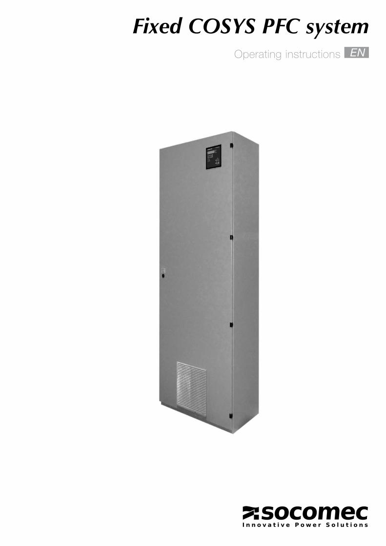
Fixed COSYS PFC systemOperating instructions EN
Co
nten
tsEN WARRANTY CONDITIONS _________________________3GENERAL SAFETY AND USAGE INSTRUCTIONS __________________________________4SYSTEM DESCRIPTION ___________________________5
General points __________________________________5Function ______________________________________5Construction ___________________________________5General characteristics ___________________________5
INSTALLATION ___________________________________6Recommendations relating to installation conditions __________________________6Connecting the input cables ______________________6Upstream protection and connection cross section ___6Technical characteristics _________________________8
COMMISSIONING AND MAINTENANCE ___________10Checking the equipment ________________________10Powering up ___________________________________10Maintenance __________________________________10
3
Fixed COSYS PFC system
Fixed COSYS PFC system - Ref.: 540538A
WARRANTY CONDITIONS
The warranty conditions are set out in the sales contract; in all other cases, the following conditions shall apply.The manufacturer guarantees its product against any manufacturing or operating faults caused by errors in design, choice of materials or manufacture, in accordance with the conditions set out below.The manufacturer may - without prior notice – modify its product in order to bring it into line with the warranty conditions or replace defective parts. The manufacturer's warranty shall not apply in the following cases:• Faults caused by designs or parts used without
consent, or supplied, by the buyer.• Replacements or repairs resulting from normal wear
and tear of parts and equipment• Damage or injury caused by negligence on the user's
part• Insufficient maintenance or incorrect use of products.• PFC system not adapted to the network.The warranty's validity period is 12 months following installation of the equipment, and may not exceed 18 months from the supply date.Parts replacements, repairs or modifications carried out by the manufacturer during the warranty period may under no circumstances be grounds for extending the
length of the warranty period.In order to benefit from this warranty, buyers must expressly inform the manufacturer - within a maximum of 8 days, beyond which the warranty shall expire – of any faults in the design, materials or manufacture, giving precise evidence to support their claim.Defective parts replaced free of charge by the manufacturer must be made available to the manufacturer, as they remain its sole property.The warranty shall not apply if the buyer has carried out modifications or repairs to the manufacturer's products without its prior consent.The manufacturer's liability is limited to the obligations described above (repairs or replacements); all other types of damage shall be excluded.
4 Fixed COSYS PFC system - Ref.: 540538A
GENERAL SAFETY AND USAGE INSTRUCTIONS
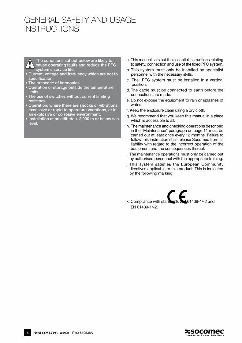
a. This manual sets out the essential instructions relating to safety, connection and use of the fixed PFC system.
b. This system must only be installed by specialist personnel with the necessary skills.
c. The PFC system must be installed in a vertical position.
d. The cable must be connected to earth before the connections are made.
e. Do not expose the equipment to rain or splashes of water.
f. Keep the enclosure clean using a dry cloth.g. We recommend that you keep this manual in a place
which is accessible to all.h. The maintenance and checking operations described
in the “Maintenance” paragraph on page 11 must be carried out at least once every 12 months. Failure to follow this instruction shall release Socomec from all liability with regard to the incorrect operation of the equipment and the consequences thereof.
i. The maintenance operations must only be carried out by authorised personnel with the appropriate training.
j. This system satisfies the European Community directives applicable to this product. This is indicated by the following marking:
k. Compliance with standards CEI 61439-1/-2 and EN 61439-1/-2.
The conditions set out below are likely to cause operating faults and reduce the PFC system's service life:
• Current, voltage and frequency which are not to specification.
• The presence of harmonics.• Operation or storage outside the temperature
limits.• The use of switches without current limiting
resistors.• Operation: where there are shocks or vibrations,
excessive or rapid temperature variations, or in an explosive or corrosive environment.
• Installation at an altitude > 2,000 m or below sea level.
5
Fixed COSYS PFC system
Fixed COSYS PFC system - Ref.: 540538A
SYSTEM DESCRIPTION
General points
Function
Construction
General characteristics
The equipment consists of a series of racks of capacitors installed in an enclosure. Depending on the models, other equipment may be present:• anti-harmonic device.• fuse combination switch.
COSYS fixed PFC system are designed to offset variable reactive energy. Reactive energy may be consumed by a factory or production unit.
• Power from 17.5 to 60 kvar.
• Harmonics from 0 to 100% in 4 stages: PFC21, PFC22, PFC23, PFC24.
• Cable input at the bottom (can be the top if required).
• Base plate optional
• Thermal regulation with fan (depending on equipment).
• Self-healing capacitors.
• Capacitor cut off from the automatic circuit in case of removal.
• Steel panel enclosure colour RAL 7035.
• IP rating IP20, IP30 depending on model.
• Rated voltage: 400 V three-phase.
• Rated frequency: 50 Hz.
• Operating temperature: -5°C to 40°C.
• Tolerance on capacitor capacity value: -5, +5%.
• Discharge device on each bank: < 50 V after 1 minute.
• Capacitor internal connection: delta.
6 Fixed COSYS PFC system - Ref.: 540538A
INSTALLATION
Failure to follow the installation instructions contained in this manual may compromise the operation and reliability of the PFC system.
Recommendations relating to installation conditions
Recommended operating temperature: between 15°C and 35°C.Relative humidity without condensation: 90% max.Maximum operating altitude: 2,000 mTake all necessary precautions to prevent splashes of water, paint or other fluids.The enclosure conforms to protection rating IP20.
It is essential to ensure that there is a clearance of 50 cm above the PFC system to allow adequate ventilation.
Connecting the input cables
The power is supplied to the terminals provided for this purpose.The power, control and measurement cables should be connected in accordance with the standards in force and good practice.The cable bushing plate should be refitted after the cable gland or other cable passage system has been fitted.
Failure to follow this instruction may seriously compromise the ventilation efficiency, reduce the cabinet's level of protection and cause the formation of hazardous material or objects.
Upstream protection and connection cross section
The selection and co-ordination of the protection devices upstream of the PFC system depend on the nominal current and cable fitting conditions.The protection devices upstream of the PFC system must conform to the safety standards in force.The cross section of the cables should be adapted to
the power of the fixed PFC system. Cables should be selected according to the current values shown in the table below, which should be increased by a coefficient of 1.43 in accordance with CEI 60831-1.
Fixed COSYS PFC system - Ref.: 540538A 7
Fixed COSYS PFC system
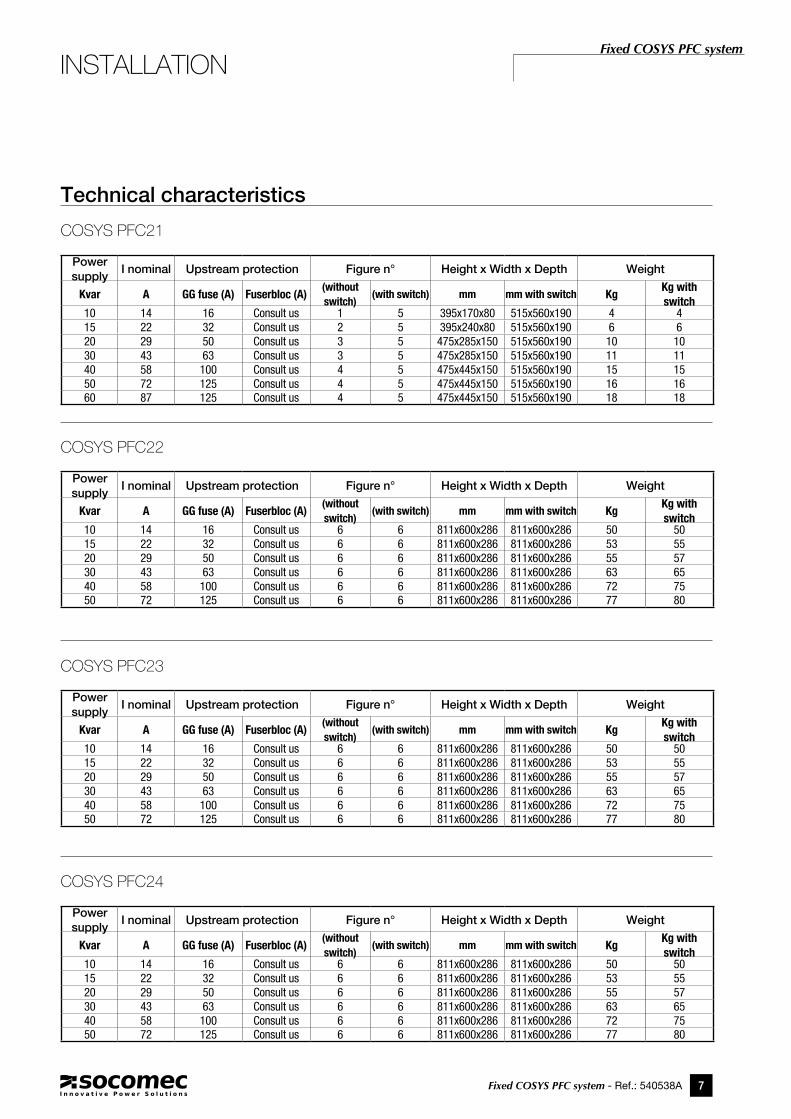
Technical characteristics
COSYS PFC21
Power supply
I nominal Upstream protection Figure n° Height x Width x Depth Weight
Kvar A GG fuse (A) Fuserbloc (A)(without switch)
(with switch) mm mm with switch KgKg with switch
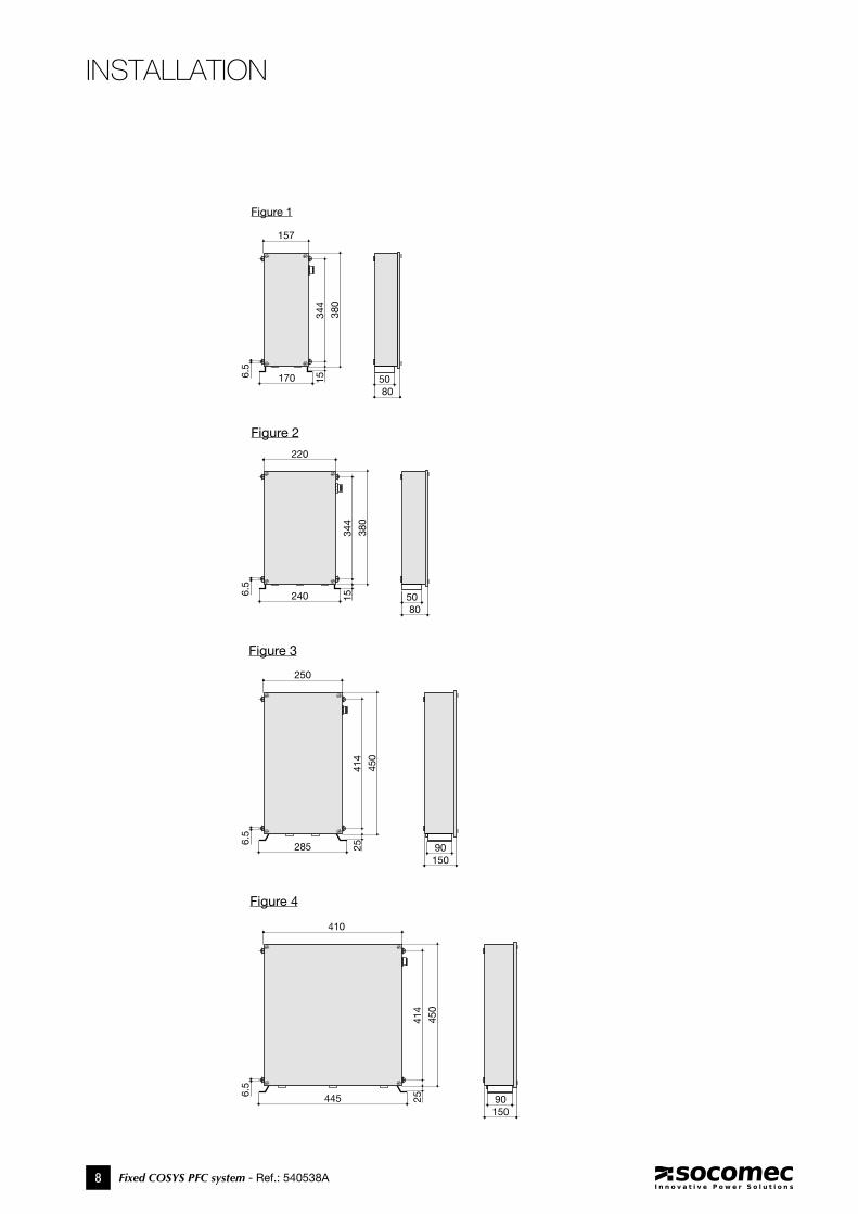
10 14 16 Consult us 1 5 395x170x80 515x560x190 4 415 22 32 Consult us 2 5 395x240x80 515x560x190 6 620 29 50 Consult us 3 5 475x285x150 515x560x190 10 1030 43 63 Consult us 3 5 475x285x150 515x560x190 11 1140 58 100 Consult us 4 5 475x445x150 515x560x190 15 1550 72 125 Consult us 4 5 475x445x150 515x560x190 16 1660 87 125 Consult us 4 5 475x445x150 515x560x190 18 18
Power supply
I nominal Upstream protection Figure n° Height x Width x Depth Weight
Kvar A GG fuse (A) Fuserbloc (A)(without switch)
(with switch) mm mm with switch KgKg with switch
10 14 16 Consult us 6 6 811x600x286 811x600x286 50 5015 22 32 Consult us 6 6 811x600x286 811x600x286 53 5520 29 50 Consult us 6 6 811x600x286 811x600x286 55 5730 43 63 Consult us 6 6 811x600x286 811x600x286 63 6540 58 100 Consult us 6 6 811x600x286 811x600x286 72 7550 72 125 Consult us 6 6 811x600x286 811x600x286 77 80
COSYS PFC22
COSYS PFC23
COSYS PFC24
INSTALLATION
8 Fixed COSYS PFC system - Ref.: 540538A
1706.5
15
8050
344
380
157
Figure 1
240
220
6.5
15
8050
344
380
Figure 2
1509025
414
450
285
250
6.5
Figure 3
1509025
414
450
445
410
6.5
Figure 4
INSTALLATION
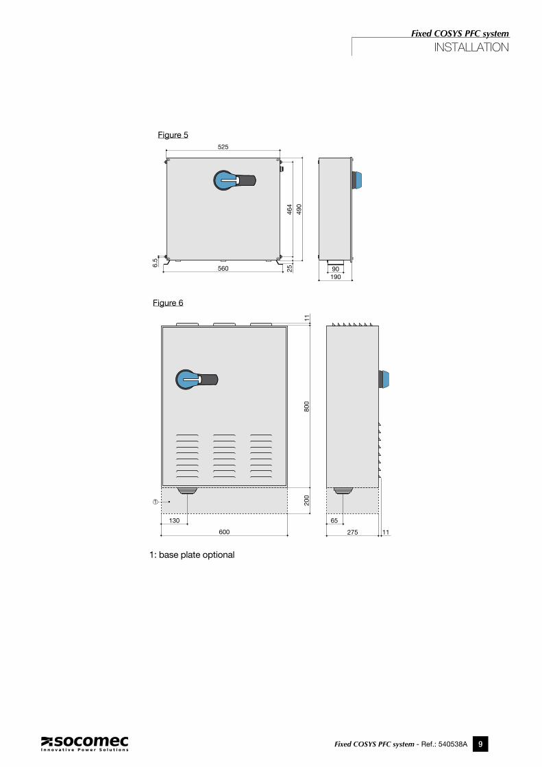
Fixed COSYS PFC system - Ref.: 540538A 9
Fixed COSYS PFC system
1909025
464
490
560
5256.
5
Figure 5
130
800
200
600 275 11
11
65
1
Figure 6
INSTALLATION
1: base plate optional
10 Fixed COSYS PFC system - Ref.: 540538A
Checking the equipment
Before commissioning the equipment, ensure that all connections are correctly tightened, as the terminals may become loose during transportation of the equip-ment from the production plant to the site (switch).
Powering up
Once the operations in the previous paragraph have been carried out, the equipment can be started by closing the upstream panel protection and the PFC system cabinet switch (depending on the model).
Maintenance
Routine maintenance of this equipment involves perio-dically checking (at least once every year) the following components:• Auxiliary circuit fuses• Capacitor fuses• Cleanliness of the ventilation grille and the filter to
ensure proper ventilation of the enclosure• Retightening of the terminals• Visual inspection of the capacitors by replacing those
that are causing deforming of the upper part of the outer enclosure.
COMMISSIONING AND MAINTENANCE
SOCOMEC can also offer:•maintenance•audit•start-up•training for your staff
Fixed COSYS PFC system - Ref.: 540538A 11
Fixed COSYS PFC system
COMMISSIONING AND MAINTENANCE
SOCOMEC - Ref.: 540538 A - 01/11
VALID FOR FRANCE
h E A d O f f I C ESOCOMEC GROUPS.A. SOCOMEC capital 11 149 200 €R.C.S. Strasbourg B 548 500 149B.P. 60010 - 1, rue de Westhouse F-67235 Benfeld Cedex - FRANCE
I n t E R n A t I O n A L S A L E S d E p A R t M E n tSOCOMEC1, rue de Westhouse - B.P. 60010 F - 67235 Benfeld Cedex - FRANCETel. +33 (0)3 88 57 41 41 - Fax +33 (0)3 88 74 08 [email protected]
Socomec worldwide
I n E U R O p E
BELGIUMSOCOMEC BELGIUM B - 1190 Brussel Tel. +32 (0)2 340 02 30 - Fax +32 (0)2 346 28 99 [email protected]
FRANCESOCOMEC F - 94132 Fontenay-sous-Bois Cedex Tel. +33 (0)1 45 14 63 30 - Fax +33 (0)1 45 14 63 38 [email protected]
GERMANYSOCOMEC GmbH D - 76275 Ettlingen Tel. +49 (0)7243 65 29 2 0 - Fax +49 (0)7243 65 29 2 13 [email protected]
ITALYSOCOMEC Elettrotecnica s.r.l. I - 20098 San Giuliano Milanese (MI) Tel. +39 02 9849821 - Fax +39 02 98243310 [email protected]
SPAINSOCOMEC ELECTRO, S.L. E - 08310 Argentona (Barcelona) Tel. +34 93 741 60 67 - Fax. +34 93 757 49 52 [email protected]
ThE NEThERLANDSSOCOMEC B.V. NL - 3991 CD Houten Tel. +31 (0)30 760 0901- Fax +31 (0)30 637 2166 [email protected]
ThE UNITED KINGDOMSOCOMEC Ltd Hitchin Hertfordshire SG4 0TY Tel. +44 (0)1462 440033 - Fax +44 (0)1462 431143 [email protected]
I n A S I A
NORTh EAST ASIASOCOMEC CHINA Co. Ltd P.R.C 200052 Shanghai - China Tel. +86 (0)21 5298 9555 - Fax +86 (0)21 6228 3468 [email protected]
SOUTh EAST ASIA & PACIFICSOCOMEC SWITCHING AND PROTECTION UBI TECHPARK - 408569 Singapore Tel. +65 65 07 94 90 - Fax +65 65 47 86 93 [email protected]
SOUTh ASIASOCOMEC INDIA 122001 Gurgaon, Haryana - India Tel. +91 124 4562 700 - Fax +91 124 4562 738 [email protected]
I n M I d d L E E A S t
UNITED ARAB EMIRATESSOCOMEC Middle East Dubai, U.A.E. Tel. +971 (0) 4 29 98 441 - Fax +971 (0)4 29 98 449 [email protected]
I n n O R t h A M E R I C A
USA, CANADA & MEXICOSOCOMEC Inc Cambridge, MA 02142 USA Tel. +1 617 245 0447 - Fax +1 617 245 0437 [email protected]
www.socomec.comNon contractual document. © 2012, Socomec SA. All rights reserved.
4e_couv_SCP_bleu_2012.indd 6 27/01/12 11:35