
FITTING INSTRUCTIONS FOR CP0313 CRASH PROTECTORS - RevZilla.com · Remove the two bolts arrowed in...
12
R&G Racing Unit 1, Shelley’s Lane, East Worldham, Alton, Hampshire, GU34 3AQ Tel: +44 (0)1420 89007 Fax: +44 (0)1420 87301 www.rg-racing.com Email: [email protected] Page | 1 FITTING INSTRUCTIONS FOR CP0313 CRASH PROTECTORS KAWASAKI ER6-N 2012 PICTURE A PICTURE B REAR OF BIKE FRONT OF BIKE PICTURE C THIS KIT CONTAINS THE ITEMS PICTURED AND LABELLED BELOW. DO NOT PROCEED UNTIL YOU ARE SURE ALL PARTS ARE PRESENT. Please note that the way the kit is packed does not necessarily represent the way of mounting to the bike Please note that in cases where kits are packed with rubber washers holding the components onto the bolt – the rubber washers should be thrown away!
Transcript of FITTING INSTRUCTIONS FOR CP0313 CRASH PROTECTORS - RevZilla.com · Remove the two bolts arrowed in...

R&G Racing
Unit 1, Shelley’s Lane, East Worldham, Alton, Hampshire, GU34 3AQ
Tel: +44 (0)1420 89007 Fax: +44 (0)1420 87301 www.rg-racing.com Email: [email protected]
Page | 1
FITTING INSTRUCTIONS FOR CP0313 CRASH PROTECTORS
KAWASAKI ER6-N 2012
PICTURE A PICTURE B
REAR OF BIKE FRONT OF BIKE
PICTURE C
THIS KIT CONTAINS THE ITEMS PICTURED AND LABELLED BELOW.
DO NOT PROCEED UNTIL YOU ARE SURE ALL PARTS ARE PRESENT.
Please note that the way the kit is packed does not necessarily represent the way of
mounting to the bike
Please note that in cases where kits are packed with rubber washers holding the components onto
the bolt – the rubber washers should be thrown away!

R&G Racing
Unit 1, Shelley’s Lane, East Worldham, Alton, Hampshire, GU34 3AQ
Tel: +44 (0)1420 89007 Fax: +44 (0)1420 87301 www.rg-racing.com Email: [email protected]
Page | 2
THE PARTS SHOWN MAY BE REPRESENTATIVE ONLY (FOR CLARITY OF INSTRUCTIONS ONLY)
LEFT HAND SIDE
RIGHT HAND SIDE
1
2
3
6
7
9
1
4
5
6
3
10
7 3
8
3
11

R&G Racing
Unit 1, Shelley’s Lane, East Worldham, Alton, Hampshire, GU34 3AQ
Tel: +44 (0)1420 89007 Fax: +44 (0)1420 87301 www.rg-racing.com Email: [email protected]
Page | 3
TOOLS REQUIRED
Socket set to include 14 and 17mm sockets and wrench.
Set of metric Allen keys to include 4 and 5mm A/F.
Torque wrench (up to 40 Nm).
LEGEND ITEM 1 = BC0002 CRASH PROTECTOR CAPS (x2).
ITEM 2 = M10x1.25x130mm LONG HEX HEAD BOLT (L-H-S FRAME/BLOCK BOLT) (x1).
ITEM 3 = M10 PLAIN WASHERS (x2).
ITEM 4 = M0297 MOUNTING BLOCK (L-H-S=LARGER) (x1).
ITEM 5 = S0322 SPACER (L-H-S= 12mm LONG) (x1).
ITEM 6 = B0431 with CS341 (10mm) (BOTH CRASH PROTECTORS) (x2).
ITEM 7 = LW0001 (M12 SHAKE PROOF WASHERS) (x2).
ITEM 8 = M10x1.25x75mm LONG HEX HEAD BOLT (L-H-S CRASH PROTECTOR BOLT) (x1).
ITEM 9 = M10x1.25x140mm LONG HEX HEAD BOLT (R-H-S FRAME/BLOCK BOLT) (x1).
ITEM 10 = M10x1.25x65mm LONG HEX HEAD BOLT (R-H-S CRASH PROTECTOR BOLT) (x1).
ITEM 11 = M0298 MOUNTING BLOCK (R-H-S=SMALLER) (x1).
ITEM 12 = LENGTH OF SELF-ADHESIVE FOAM (x1) (NOT SHOWN).
PICTURE D PICTURE E
PICTURE F PICTURE G

R&G Racing
Unit 1, Shelley’s Lane, East Worldham, Alton, Hampshire, GU34 3AQ
Tel: +44 (0)1420 89007 Fax: +44 (0)1420 87301 www.rg-racing.com Email: [email protected]
Page | 4
PICTURE H PICTURE I
FITTING INSTRUCTIONS
Near side (left side as you sit on bike) Remove the two bolts arrowed in pictures D and E, and remove the left hand side fairing.
Remove the engine/frame bolt in position arrowed in picture F (using 14mm socket) be careful as
the nut may fall out (this must be reused on assembly).
Cut and stick the self-adhesive foam in the positions arrowed in picture G (this helps prevent
marking of the frame on assembly.
Slide one of the 10mm washers (item 3) onto the M10 hexagon headed bolt (item 2=130mm long)
so washer sits against head of the bolt.
Place the mounting block (item 4) in position as shown in picture G.
Place the bolt with washer though the unthreaded hole in the mounting block, through the frame
and original frame/engine spacer, please ensure the in-board nut is in position and tighten (Do not
exceed 40 Nm of torque).
Replace left hand side fairing.
Slide one of the 10mm washers (item 3) onto the M10 hexagon headed bolt (item 8=75mm long)
so the washer sits against head of the bolt as shown in picture H.
Next slide one of the serrated locking washers (item 7) over the bolt so it sits against the washer
just fitted as shown in picture H.
Next slide the bolt with washers through either crash protector (item 6) so head of bolt goes into
counter-bore in crash protector as shown in picture H.
Place one of the spacer (item 5) over the exposed end of the bolt so it sits against the crash
protector as shown in picture H.
Offer the crash protector assembly up to the threaded mounting hole in the mounting block as
shown in picture I.
Finally tighten the crash protector bolt until you feel some compression from inside the protector
using 17mm socket and wrench. PLEASE NOTE THE CRASH PROTECTOR MUST BE
POSITIONED AS IN PICTURE ‘C’ WITH BIGGER END TOWARD FRONT OF BIKE.
Turn a little more so that you feel the compression increase slightly. Then apply a quarter turn.
Do not over tighten as damage can occur to the bike. Do not exceed 40 Nm of torque. Please
ensure the crash protector does not come into contact with the fairing panel as you tighten the bolt.
If not already fitted fit bubble sticker into recess of crash protector cap.
Fit crash protector cap into crash protector.

R&G Racing
Unit 1, Shelley’s Lane, East Worldham, Alton, Hampshire, GU34 3AQ
Tel: +44 (0)1420 89007 Fax: +44 (0)1420 87301 www.rg-racing.com Email: [email protected]
Page | 5
PICTURE J PICTURE K
PICTURE L PICTURE M
PICTURE N PICTURE O

R&G Racing
Unit 1, Shelley’s Lane, East Worldham, Alton, Hampshire, GU34 3AQ
Tel: +44 (0)1420 89007 Fax: +44 (0)1420 87301 www.rg-racing.com Email: [email protected]
Page | 6
Off side (right side as you sit on bike) Remove the two bolts arrowed in pictures J and K, and remove the right hand side fairing.
Remove the engine/frame bolt in position arrowed in picture L (using 14mm socket) be careful as
the nut may fall out (this must be reused on assembly).
Cut and stick the self-adhesive foam in the positions arrowed in picture M (this helps prevent
marking of the frame on assembly.
Slide one of the 10mm washers (item 3) onto the M10 hexagon headed bolt (item 9=140mm long)
so washer sits against head of the bolt.
Place the mounting block (item 11) in position as shown in picture M.
Place the bolt with washer though the unthreaded hole in the mounting block, through the frame
and original frame/engine spacer, please ensure the in-board nut is in position and tighten (Do not
exceed 40 Nm of torque).
Replace left hand side fairing.
Slide one of the 10mm washers (item 3) onto the M10 hexagon headed bolt (item 10=65mm long)
so the washer sits against head of the bolt as shown in picture N.
Next slide one of the serrated locking washers (item 7) over the bolt so it sits against the washer
just fitted as shown in picture N.
Next slide the bolt with washers the remaining crash protector (item 6) so head of bolt goes into
counter-bore in crash protector as shown in picture N.
Offer the crash protector assembly up to the threaded mounting hole in the mounting block as
shown in picture O.
Finally tighten the crash protector bolt until you feel some compression from inside the protector
using 17mm socket and wrench. PLEASE NOTE THE CRASH PROTECTOR MUST BE
POSITIONED AS IN PICTURE ‘C’ WITH BIGGER END TOWARD FRONT OF BIKE.
Turn a little more so that you feel the compression increase slightly. Then apply a quarter turn.
Do not over tighten as damage can occur to the bike. Do not exceed 40 Nm of torque. Please
ensure the crash protector does not come into contact with the fairing panel as you tighten the bolt.
If not already fitted fit bubble sticker into recess of crash protector cap.
Fit crash protector cap into crash protector.
Place one of the longer spacers over the exposed end of the bolt so it sits against the crash
protector as shown in picture ‘H’ (please note the slightly larger diameter sits against the crash
protector.
Offer the crash protector assembly up to the engine/frame mounting hole as shown in picture ‘I’.
Finally tighten the crash protector bolt until you feel some compression from inside the protector
using 17mm socket and wrench. PLEASE NOTE THE CRASH PROTECTOR MUST BE
POSITIONED AS IN PICTURE ‘C’ WITH BIGGER END TOWARD FRONT OF BIKE.
Turn a little more so that you feel the compression increase slightly. Then apply a quarter turn.
Do not over tighten as damage can occur to the bike. Do not exceed 40Nm of torque. Please
ensure the crash protector does not come into contact with the fairing panel as you tighten the bolt.
If not already fitted fit bubble sticker into recess of crash protector cap.
Fit crash protector cap into crash protector.
Issue 1 20/04/2012 (NSY)

R&G Racing
Unit 1, Shelley’s Lane, East Worldham, Alton, Hampshire, GU34 3AQ
Tel: +44 (0)1420 89007 Fax: +44 (0)1420 87301 www.rg-racing.com Email: [email protected]
Page | 7
CONSUMER NOTICE
The catalogue description and any exhibition of samples are only broad indications of the Products and R&G may make design
changes which do not diminish their performance or visual appeal and supplying them in such state shall conform to the order. The Buyer acknowledges no representation or warranty (other than as to title) has been given or will apply to the Products other than those
in R&G’s order or confirmation and the Buyer confirms it has chosen the Products as being of merchantable quality and suitable for
its particular purposes. Where R&G fits the Products or undertakes other services it shall exercise reasonable skill and care and rectify any fault free of charge unless the workmanship has been disturbed. The Buyer is responsible for ensuring that the warranty on the
motorcycle is not affected by the fitting of the Products. On return of any defective Products R&G shall at its option either supply a
replacement or refund the purchase money but shall not be liable if the Products have been modified or used or maintained otherwise than in accordance with R&G’s or manufacturer’s instructions and good engineering practice or if the defect arises from accident or
neglect. Other than identified above and subject to R&G not limiting its liability for causing death and personal injury, it shall not be
liable for indirect or consequential loss and otherwise its liability shall be limited to the amounts paid by the Buyer for the Products or the fitting or service concerned. These terms do not affect the Buyer’s statutory rights.
R&G RACING RETURNS POLICY (NON-FAULTY GOODS)
Returns must be pre-authorised (if not pre-authorised the return will be rejected). Goods may only be returned direct to us if they were purchased direct from us (customer must prove if necessary). Otherwise to be returned to original vendor. Goods must be in re-
sellable condition, in the opinion of R&G Racing. All returns are subject to a 25% restocking and handling fee (25% of the gross value
exc. P&P – at the prevailing price at time of purchase). The customer must pay any and all carriage charges. No returns of discontinued products, unless within 14 days of purchase. This policy does not affect your statutory rights and does not refer to faulty
goods.
R&G Racing
Unit 1, Shelley’s Lane, East Worldham, Alton, Hampshire, GU34 3AQ
Tel: +44 (0)1420 89007 Fax: +44 (0)1420 87301 www.rg-racing.com Email: [email protected]
Page | 8
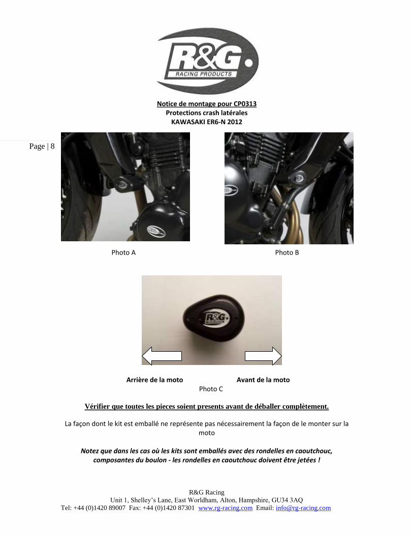
Notice de montage pour CP0313 Protections crash latérales
KAWASAKI ER6-N 2012
Photo A Photo B Arrière de la moto Avant de la moto
Photo C
Vérifier que toutes les pieces soient presents avant de déballer complètement.
La façon dont le kit est emballé ne représente pas nécessairement la façon de le monter sur la moto
Notez que dans les cas où les kits sont emballés avec des rondelles en caoutchouc,
composantes du boulon - les rondelles en caoutchouc doivent être jetées !

R&G Racing
Unit 1, Shelley’s Lane, East Worldham, Alton, Hampshire, GU34 3AQ
Tel: +44 (0)1420 89007 Fax: +44 (0)1420 87301 www.rg-racing.com Email: [email protected]
Page | 9
Les parties représentées peuvent parfois être uniquement représentatives (Pour la clarté des explications)
Coté gauche
Coté droit
1
2
3
6
7
9
1
4
5
6
3
10
7
3
8
3
11

R&G Racing
Unit 1, Shelley’s Lane, East Worldham, Alton, Hampshire, GU34 3AQ
Tel: +44 (0)1420 89007 Fax: +44 (0)1420 87301 www.rg-racing.com Email: [email protected]
Page | 10
Outils requis
Clés de 14 et 17mm
Clés Allen de 4 et 5mm
Clé dynamométrique réglable à plus de 40 Nm LEGENDE Article 1 = BC0002 Capuchons de protections crash (x2). Article 2 = M10x1.25x130mm Long boulon à tête hexagonale (Boulon de bloc/cadre coté gauche) (x1). Article 3 = M10 Rondelles plates (x2). Article 4 = M0297 Bloc de montage (coté gauche = le plus large) (x1). Article 5 = S0322 Entretoise (Coté gauche = 12mm de long) (x2). Article 6 = B0431 avec CS341 (10mm) (Les 2 protections crash) (x2). Article 7 = LW0001 (M12 Rondelles Shake proof) (x2). Article 8 = M10x1.25x75mm Long boulon à tête hexagonale (Boulon de protection crash coté gauche) (x1). Article 9 = M10x1.25x140mm Long boulon à tête hexagonale (Boulon de bloc/cadre coté droit) (x1). Article 10 = M10x1.25x65mm Long boulon à tête hexagonale (Boulon de bloc/cadre coté droit) (x1). Article 11 = M0298 Bloc de montage (coté droit = le plus petit) (x1). Article 12 = Longueur de mousse autocollante (x1) (non illustrée).
Notices de montage
Coté gauche assis sur la moto:
Enlever les 2 boulons (photo D et E), puis Enlever le carénage coté gauche. Enlever le boulon de cadre/moteur en position indiquée en F (avec une clé de 14mm). Attention
à ce que l’écrou ne tombe pas (Il doit être réutilisé plus tard). Couper et coller la mousse autocollante en position comme sur la photo G (cela aide à empêcher
le marquage sur le cadre). Glisser une des rondelles de 10mm (article 3) sur le boulon M10 à tête hexagonale (article
2=130mm de long) de sorte à ce que la rondelle se mettre contre la tête du boulon. Placer le bloc de montage (article 4) en position (photo G). Placer le boulon avec la rondelle à travers le trou non fileté dans le bloc de montage, à travers le
cadre et l’entretoise du cadre/moteur. S’assurer que l’écrou intérieur soit bien serré en position (Ne pas excéder 40Nm de couple).
Remettre le carénage coté gauche. Glisser une des rondelles de 10mm (article 3) sur le boulon à tête hexagonale M10 (article
8=75mm de long) de façon à ce que la rondelle se mette contre la tête du boulon (photo H). Glisser une des rondelles de blocage (article 7) autour du boulon de façon à ce que cette rondelle
se mette contre la rondelle tout juste installée (photo H). Glisser ensuite le boulon avec les rondelles à travers l’une ou l’autre protection (article 6) de
façon à ce que la tête du boulon aille en contre alésage dans la protection (photo H). Placer une des entretoises (article 5) autour de l’extrémité du boulon se sorte à ce qu’elle aille
contre la protection (photo H).

R&G Racing
Unit 1, Shelley’s Lane, East Worldham, Alton, Hampshire, GU34 3AQ
Tel: +44 (0)1420 89007 Fax: +44 (0)1420 87301 www.rg-racing.com Email: [email protected]
Page | 11
Poser l’ensemble sur le support dans le bloc de montage (photo I). Poser la protection crash sur le trou du support dans le bloc de montage (photo I)
Serrer les boulons de la protection jusqu’à ce que vous sentiez une légère compression de l’intérieur de la protection, à l’aide d’une clé de 17mm. NOTEZ QUE LA PROTECTION CRASH DOIT ETRE POSITIONNEE COMME SUR LA PHOTO « C » AVEC LA PLUS GROSSE EXTREMITE VERS L’AVANT DE LA MOTO. Tourner un peu plus pour accroitre la compression. Faire un quart de tour.
NE PAS SERRER TROP FORT AU RISQUE D’ENDOMMAGER LE SYSTEME. NE PAS SERRER A PLUS DE 40nm.
S’assurer que la protection n’entre pas en contact avec le carénage puis s’assurer également que l’axe est bien en place.
Mettre les capuchons R&G en gomme sur la protection.
Coté droit assis sur la moto: Enlever les 2 boulons (photo J et K), puis enlever le carénage coté droit. Enlever le boulon de moteur / cadre en position fléchée en photo L (à l’aide d’une clé de 14mm)
Attention à ce que l’écrou ne tombe pas. (Il sera réutilisé dans l’assemblage). Couper et coller la mousse autocollante dans les positions indiquées en photo M (Cela empêche
le marquage). Glisser une des rondelles de 10mm (article 3) sur le boulon à tête hexagonale (article 9=140mm
de long) de façon à ce que la rondelle se mette contre la tête du boulon. Placer le bloc de montage (article 11) en position (photo M). Placer le boulon avec la rondelle à travers le trou non fileté dans le bloc de montage, à travers le
cadre et l’entretoise de cadre / Entretoise de moteur d’origine. S’assurer que l’écrou intérieur soit bien fixer en position. (Ne pas excéder 40Nm de couple).
Remettre le carénage coté gauche. Glisser une des rondelles de 10mm (article 3) sur le boulon à tête hexagonale M10 (article
10=65mm de long) afin que la rondelle se mette contre la tête du boulon (photo N). Prendre une des rondelles de blocage (Article 7) et la placer contre la rondelle place tout juste
installée (photo N). Placer cet ensemble à travers la protection restante (article 6) pour que la tête du boulon et les
rondelles aillent en contre alésage dans la protection (photo N). Poser la protection crash sur le trou du support dans le bloc de montage (photo O)
Serrer les boulons de la protection jusqu’à ce que vous sentiez une légère compression de l’intérieur de la protection, à l’aide d’une clé de 17mm. NOTEZ QUE LA PROTECTION CRASH DOIT ETRE POSITIONNEE COMME SUR LA PHOTO « C » AVEC LA PLUS GROSSE EXTREMITE VERS L’AVANT DE LA MOTO. Tourner un peu plus pour accroitre la compression. Faire un quart de tour.
NE PAS SERRER TROP FORT AU RISQUE D’ENDOMMAGER LE SYSTEME. NE PAS SERRER A PLUS DE 40nm.
S’assurer que la protection n’entre pas en contact avec le carénage puis s’assurer également que l’axe est bien en place.
Mettre les capuchons R&G en gomme sur la protection.

R&G Racing
Unit 1, Shelley’s Lane, East Worldham, Alton, Hampshire, GU34 3AQ
Tel: +44 (0)1420 89007 Fax: +44 (0)1420 87301 www.rg-racing.com Email: [email protected]
Page | 12
Placer une des grandes entretoises autour de l’extrémité du boulon pour qu’elle se mette contre le protection (photo H) (Note que le diamètre légèrement plus large se met contre la protection).
Poser la protection crash sur le trou du support de moteur / cadre (photo I)
Serrer les boulons de la protection jusqu’à ce que vous sentiez une légère compression de l’intérieur de la protection, à l’aide d’une clé de 17mm. NOTEZ QUE LA PROTECTION CRASH DOIT ETRE POSITIONNEE COMME SUR LA PHOTO « C » AVEC LA PLUS GROSSE EXTREMITE VERS L’AVANT DE LA MOTO. Tourner un peu plus pour accroitre la compression. Faire un quart de tour.
NE PAS SERRER TROP FORT AU RISQUE D’ENDOMMAGER LE SYSTEME. NE PAS SERRER A PLUS DE 40nm.
S’assurer que la protection n’entre pas en contact avec le carénage puis s’assurer également que l’axe est bien en place.
Mettre les capuchons R&G en gomme sur la protection.
Issue 1 20/04/2012 (NSY)
CONSUMER NOTICE
The catalogue description and any exhibition of samples are only broad indications of the Products and R&G may make design
changes which do not diminish their performance or visual appeal and supplying them in such state shall conform to the order. The Buyer acknowledges no representation or warranty (other than as to title) has been given or will apply to the Products other than those
in R&G’s order or confirmation and the Buyer confirms it has chosen the Products as being of merchantable quality and suitable for
its particular purposes. Where R&G fits the Products or undertakes other services it shall exercise reasonable skill and care and rectify any fault free of charge unless the workmanship has been disturbed. The Buyer is responsible for ensuring that the warranty on the
motorcycle is not affected by the fitting of the Products. On return of any defective Products R&G shall at its option either supply a
replacement or refund the purchase money but shall not be liable if the Products have been modified or used or maintained otherwise than in accordance with R&G’s or manufacturer’s instructions and good engineering practice or if the defect arises from accident or
neglect. Other than identified above and subject to R&G not limiting its liability for causing death and personal injury, it shall not be
liable for indirect or consequential loss and otherwise its liability shall be limited to the amounts paid by the Buyer for the Products or the fitting or service concerned. These terms do not affect the Buyer’s statutory rights.
R&G RACING RETURNS POLICY (NON-FAULTY GOODS)
Returns must be pre-authorised (if not pre-authorised the return will be rejected). Goods may only be returned direct to us if they were purchased direct from us (customer must prove if necessary). Otherwise to be returned to original vendor. Goods must be in re-
sellable condition, in the opinion of R&G Racing. All returns are subject to a 25% restocking and handling fee (25% of the gross value
exc. P&P – at the prevailing price at time of purchase). The customer must pay any and all carriage charges. No returns of discontinued products, unless within 14 days of purchase. This policy does not affect your statutory rights and does not refer to faulty
goods.