Fission Chamber Design - NEUP Documents/NEET-2.5 Material...Temperature Fission Chamber . August...
101
ORNL/LTR-2012/331 Materials Selection for a High- Temperature Fission Chamber August 2012
Transcript of Fission Chamber Design - NEUP Documents/NEET-2.5 Material...Temperature Fission Chamber . August...
ORNL/LTR-2012/331
Materials Selection for a High-Temperature Fission Chamber
August 2012

DOCUMENT AVAILABILITY Reports produced after January 1, 1996, are generally available free via the U.S. Department of Energy (DOE) Information Bridge. Web site http://www.osti.gov/bridge Reports produced before January 1, 1996, may be purchased by members of the public from the following source. National Technical Information Service 5285 Port Royal Road Springfield, VA 22161 Telephone 703-605-6000 (1-800-553-6847) TDD 703-487-4639 Fax 703-605-6900 E-mail [email protected] Web site http://www.ntis.gov/support/ordernowabout.htm Reports are available to DOE employees, DOE contractors, Energy Technology Data Exchange (ETDE) representatives, and International Nuclear Information System (INIS) representatives from the following source. Office of Scientific and Technical Information P.O. Box 62 Oak Ridge, TN 37831 Telephone 865-576-8401 Fax 865-576-5728 E-mail [email protected] Web site http://www.osti.gov/contact.html
This report was prepared as an account of work sponsored by an agency of the United States Government. Neither the United States Government nor any agency thereof, nor any of their employees, makes any warranty, express or implied, or assumes any legal liability or responsibility for the accuracy, completeness, or usefulness of any information, apparatus, product, or process disclosed, or represents that its use would not infringe privately owned rights. Reference herein to any specific commercial product, process, or service by trade name, trademark, manufacturer, or otherwise, does not necessarily constitute or imply its endorsement, recommendation, or favoring by the United States Government or any agency thereof. The views and opinions of authors expressed herein do not necessarily state or reflect those of the United States Government or any agency thereof.

ORNL/LTR-2012/331
Global Nuclear Security and Technology Division
Materials Selection for a High-Temperature Fission Chamber
Z. W. Bell, M. J. Harrison Global Nuclear Security and Technology Division
D. E. Holcomb
Reactors and Nuclear Systems Division
C. L. Britton, Jr., N. D. Bull, R. J. B. Warmack Measurement Science and Systems Engineering Division
M. J. Lance, K. J. Leonard, Y. Katoh, R. G. Miller
Materials Science and Technology Division
R. T. Mayes Chemical Sciences Division
D. R. Giuliano, A. M. Aaron
Fuel Cycle & Isotopes Division
Date Published: August 2012
Prepared by OAK RIDGE NATIONAL LABORATORY
Oak Ridge, Tennessee 37831-6285 managed by
UT-BATTELLE, LLC for the
U.S. DEPARTMENT OF ENERGY under contract DE-AC05-00OR22725

This page intentionally left blank

iii
CONTENTS
Page
LIST OF FIGURES ...................................................................................................................................... v LIST OF TABLES ...................................................................................................................................... vii ABBREVIATED TERMS ........................................................................................................................... ix ABSTRACT ................................................................................................................................................. xi 1. INTRODUCTION .................................................................................................................................. 1 2. BASIC PRINCIPLES OF FISSION CHAMBER OPERATION .......................................................... 3
2.1 CAPTURE OF NEUTRONS ........................................................................................................ 5 2.2 SENSITIVITY .............................................................................................................................. 5 2.3 CAPACITANCE ........................................................................................................................... 7 2.4 GAS ............................................................................................................................................... 8 2.5 PRESSURE AND ELECTRIC FIELD ......................................................................................... 9 2.6 THERMAL LOADING .............................................................................................................. 10
3. DETECTOR ELECTRONICS ............................................................................................................. 11 3.1 THEORY AND BACKGROUND .............................................................................................. 11 3.2 PULSE MODE (LOW RATE) .................................................................................................... 12 3.3 MEAN-SQUARE VOLTAGE MODE OR CAMPBELLING MODE (LOW-MEDIUM
RATE) ......................................................................................................................................... 14 3.4 CURRENT MODE (HIGH RATE) ............................................................................................ 14 3.5 EXTENDED-RANGE COUNTING (LOW-HIGH RATES) ..................................................... 15 3.6 LOGARITHMIC COUNTING (LOW-HIGH RATES)10, .......................................................... 17 3.7 EFFECTS OF CABLES ON THE METHODS .......................................................................... 19 3.8 IMPLEMENTATION OF PULSE MODE ................................................................................. 20 3.9 MEAN-SQUARE VOLTAGE MODE OR CAMPBELLING MODE ....................................... 21 3.10 CURRENT MODE ..................................................................................................................... 22
4. URANIUM COATINGS ...................................................................................................................... 24 4.1 CHOICE OF FISSILE MATERIAL ........................................................................................... 24 4.2 METHODS OF ATTACHMENT ............................................................................................... 25 4.3 DESCRIPTION OF ELECTRODEPOSITION .......................................................................... 25 4.4 FAILURE MECHANISMS ........................................................................................................ 26
5. CHAMBER DESIGN ........................................................................................................................... 28 5.1 METALS ..................................................................................................................................... 28
5.1.1 Refractory Metal Alloys ................................................................................................... 33 5.1.2 Ni-base Alloys .................................................................................................................. 37 5.1.3 Summary ........................................................................................................................... 46
5.2 JOINING ..................................................................................................................................... 47 5.3 MATERIALS FOR CONNECTORS AND LEADS .................................................................. 49 5.4 CARBON/CARBIDE CERAMICS ............................................................................................ 49
5.4.1 SiC .................................................................................................................................... 50 5.4.2 Thermodynamic Stability of Carbon in Nitrogen at High Temperatures ......................... 53
5.5 INSULATORS ............................................................................................................................ 55 5.5.1 Bulk Insulator ................................................................................................................... 56 5.5.2 Insulator-to-Metal Seal ..................................................................................................... 56 5.5.3 Electrical Feed-Throughs .................................................................................................. 57 5.5.4 Nipple for Fill Gas Insertion ............................................................................................. 57 5.5.5 Chemical and Mechanical Stability .................................................................................. 57 5.5.6 Alumina to Alumina Joint ................................................................................................. 57

iv
5.5.7 Alternative Design: Alumina Substrates for the Conducting Cylinders ........................... 58 5.6 NEUTRON TRANSPORT ......................................................................................................... 58
5.6.1 Probability of Detection .................................................................................................... 58 5.6.2 Fission Production Efficiency ........................................................................................... 63 5.6.3 Sensitivity ......................................................................................................................... 64
5.7 FILL GAS ................................................................................................................................... 65 5.7.1 Gas Selection .................................................................................................................... 65 5.7.2 Contamination ................................................................................................................... 69 5.7.3 Helium Permeation ........................................................................................................... 69
5.8 SIZING ANALYSIS ................................................................................................................... 71 5.8.2 Materials and Methods ...................................................................................................... 73 5.8.3 Results ............................................................................................................................... 78 5.8.4 Conclusions ....................................................................................................................... 80
5.9 CHAMBER RECOMMENDATION .......................................................................................... 80 6. REFERENCES ..................................................................................................................................... 82

v
LIST OF FIGURES
Figure Page
Fig. 1. Schematic of fission chamber (not to scale). ..................................................................................... 3 Fig. 2. Time to detect a step change in k. ...................................................................................................... 7 Fig. 3. Schematic of transmission line arrangement with readout. ............................................................... 8 Fig. 4. Range of values of neutron flux (n/cm2/s) at the projected location of the detector. ....................... 11 Fig. 5. Campbell’s theorem illustration. ..................................................................................................... 12 Fig. 6. A simple R-C detector termination. ................................................................................................. 13 Fig. 7. Mean-square voltage (MSV) processing chain. ............................................................................... 14 Fig. 8. (a) Block diagram and (b) Normalized response ............................................................................. 16 Fig. 9. Simple Model of Logarithmic Processor. ........................................................................................ 17 Fig. 10. 2×10⁶ e-h pairs/event collected in 500ns superimposed on DC current
from 10-11 to 10-4 A. ............................................................................................................................ 18 Fig. 11. Notional Pulse Processing System Using Logarithmic Processor. ................................................ 18 Fig. 12. Canonical transmission line model. ............................................................................................... 19 Fig. 13. Transistor termination of cable. ..................................................................................................... 20 Fig. 14. Parallel input technique. ................................................................................................................ 21 Fig. 15. Pulse counting system. .................................................................................................................. 21 Fig. 16. Advanced wide range system using MSV. .................................................................................... 22 Fig. 17. Autoranging current-mode system. ............................................................................................... 23 Fig. 18. U-O-N phase diagram at 1273 K. Pressures are expressed in atmospheres. ................................. 24 Fig. 19. Summary of creep rupture performance illustrating upper temperature limits of various
materials systems, after [19]. .............................................................................................................. 28 Fig. 20. Operating temperature windows for various alloy types. .............................................................. 29 Fig. 21. The design stress versus temperature of allowable operating limits for 316LN grade
stainless. .............................................................................................................................................. 30 Fig. 22. The design stress versus temperature of allowable operating limits for oxide dispersive
strengthened MA-956 oxide dispersion strengthened austenitic stainless. ......................................... 31 Fig. 23. Liquid Li compatibility of various structural materials, from [26]. ............................................... 32 Fig. 24. Operating limits for pure molybdenum bound by strength and creep limits,
recrystallization temperature and low temperature radiation embrittlement. ...................................... 33 Fig. 25. The design stress versus temperature of allowable operating limits for Nb-1Zr24. ....................... 34 Fig. 26. Unirradiated and irradiated (0.1–5 dpa) ultimate tensile strengths (UTS) and uniform
elongation (eU) of Nb–1Zr. ................................................................................................................. 35 Fig. 27. Weight change after 1 hour at 1073 K of different materials measured through
thermogravimetric analysis. ................................................................................................................ 37 Fig. 28. Comparison of creep data for various Ni-base superalloys. .......................................................... 39 Fig. 29. Comparison of operating windows of select Ni-base alloys. ......................................................... 40 Fig. 30. Void swelling as a function of temperature for pure Ni irradiated to approximately 1 dpa
by neutrons (10-7 dpa/sec) and 5 MeV Ni ions (3×10⁻³ dpa/sec), from [63]. ........................................ 41 Fig. 31. Free energy of formation for various oxides, adapted from [50]. .................................................. 43 Fig. 32. Temperature dependence of electrical resistivity for commercial CVD SiC................................. 52 Fig. 33. Electrical conductivity of commercial high purity CVD SiC after neutron irradiation at
elevated temperatures. ......................................................................................................................... 53 Fig. 34. Mass Distribution of Fission Products for 235U. ............................................................................ 59 Fig. 35. Probability of detection for U2N3 NRLs at various minimum measureable energy settings. ........ 60 Fig. 36. Probability of detection for U3O8 NRLs at various minimum measureable energy settings. ........ 61 Fig. 37. Comparison of U2N3 and U3O8 probabilities of detection. ............................................................ 61

vi
Fig. 38. General fission chamber geometry modeled to estimate necessary gas chamber thickness. ......... 62 Fig. 39. Energy deposition spectra for varying gas region thicknesses. ..................................................... 62 Fig. 40. General MCNP geometry model for FPE calculations. ................................................................. 63 Fig. 41. FPE of four fission chamber designs as a function of thickness of NRLs. .................................... 64 Fig. 42. Sensitivity as a function of NRL thickness. ................................................................................... 64 Fig. 43. Optimal NRL thickness values and corresponding sensitivity for each design considered. .......... 65 Fig. 44. Parallel-plate ion chamber for testing performance of various gas mixtures. ............................... 67 Fig. 45. Photograph of oscilloscope traces showing the preamplifier output (blue) and shaper
output (yellow). ................................................................................................................................... 68 Fig. 46. Multichannel analysis of shaper-amplifier output with various mixtures. .................................... 68 Fig. 47. Risetime of preamplifier pulses for various gases. ........................................................................ 69 Fig. 48. Relative concentration of helium in a semi-infinite block of alumina for various times
after the start of diffusion. ................................................................................................................... 70 Fig. 49. Fission Chamber featuring limited dimensions of the outer shell. (Dimensions in cm). ............... 72 Fig. 50. Fission Chamber model with 2mm thick walls. The features of the top and bottom
interfaces show the merged geometry. ................................................................................................ 73 Fig. 51 Fixtures used to stabilize the model. ............................................................................................... 75 Fig. 52. Loads applied to the model of the Fission Chamber. .................................................................... 76 Fig. 53. Mesh detail of the Fission Chamber Model. .................................................................................. 77 Fig. 54. Factor of Safety results for SiC Hexoloy SA. ................................................................................ 78 Fig. 55. Factor of Safety results for alumina. .............................................................................................. 79
vii
LIST OF TABLES
Table Page
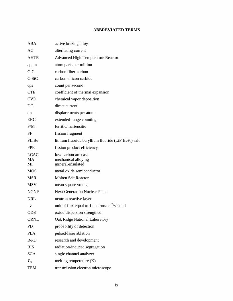
Table 1. Critical design specifications .......................................................................................................... 1 Table 2. Maximum use temperature of structural alloys in direct contact with high-purity liquid
metal coolants ............................................................................................................................. 36 Table 3. Table of standard free energies of formation of fluoride compounds at 800 and 1000 K,
from [77] ..................................................................................................................................... 44 Table 4. Nitridation resistance of select alloys in ammonia at 1253 K for 168 h, adapted from [81] ........ 45 Table 5. Diffusion data at 1200 K for possible coating/substrate combinations ......................................... 46 Table 6. Summary ranking of carbon/carbide materials ............................................................................. 50 Table 7. Temperature dependence of equilibrium constant of C2N2 formation and of degree of
transformation at equilibrium ..................................................................................................... 54 Table 8. Representative Fission Products Effective Ranges ....................................................................... 60 Table 9. Range of representative fission products for noble gases at (STP) ............................................... 66 Table 10. Material Properties for Saint-Gobain Hexoloy SA90 .................................................................. 74 Table 11. Material Properties for alumina, SolidWorks Material ............................................................... 74

This page intentionally left blank
ix
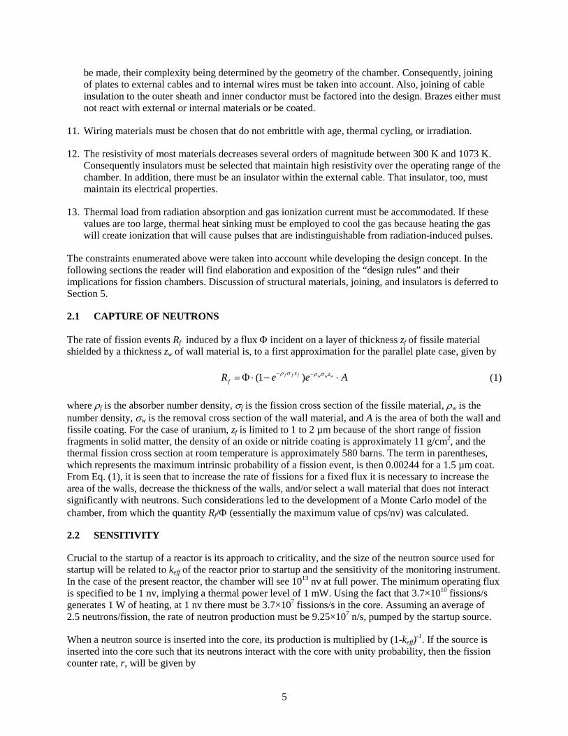
ABBREVIATED TERMS
ABA active brazing alloy
AC alternating current
AHTR Advanced High-Temperature Reactor
appm atom parts per million
C-C carbon fiber-carbon C-SiC carbon-silicon carbide cps count per second CTE coefficient of thermal expansion CVD chemical vapor deposition DC direct current dpa displacements per atom ERC extended-range counting F/M ferritic/martensitic
FF fission fragment
FLiBe lithium fluoride beryllium fluoride (LiF-BeF2) salt
FPE fission product efficiency
LCAC low-carbon arc cast MA mechanical alloying MI mineral-insulated MOS metal oxide semiconductor MSR Molten Salt Reactor MSV mean square voltage
NGNP Next Generation Nuclear Plant
NRL neutron reactive layer
nv unit of flux equal to 1 neutron/cm2/second ODS oxide-dispersion strengthed ORNL Oak Ridge National Laboratory
PD probability of detection
PLA pulsed-laser ablation R&D research and development RIS radiation-induced segregation SCA single channel analyzer
Tm melting temperature (K)
TEM transmission electron microscope

x
VG vacuum grade

xi
ABSTRACT
Component materials and processes were investigated for fission chambers suitable for operation in reactors cooled by molten fluoride salt (FLiBe) or high-temperature gas (flowing He). The device is envisioned to be a two-gap, three-electrode instrument constructed from concentric cylinders of oxide-dispersion-strengthened nickel held apart by alumina insulators, with an exterior diameter of 5 cm and length of 30 cm, and using a noble gas–nitrogen fill gas. A carbon or zeolite getter will be contained within the inner cylinder to trap fission fragments and active impurities liberated within the chamber. The chamber is expected to use approximately 5 g of 235U (as U2N3) spread over an area of approximately 640 cm2. The design’s thermal neutron sensitivity is 1 count per second per unit incident flux (1 cps/nvth) and it will function in temperatures up to 1073 K.

xii
This page intentionally left blank

1
1. INTRODUCTION
The scope of this task is to enumerate and evaluate candidate technologies for in-core fission chambers to monitor reactor power level via measurements of neutron flux from startup through full power. The critical design specifications are summarized in Table 1.
Table 1. Critical design specifications
Minimum operating temperature (K) 300
Maximum operating temperature (K) 1073
Thermal flux at 100% power (neutrons/cm2/s) 1013
Gamma dose rate (MGy/h) 6
Lifetime (years) 2
Ideally, the chambers will operate over 13 orders of magnitude, from startup through full power. At startup (i.e., at a flux of a few neutrons per square centimeter per second), the chamber will produce well-defined, well-separated pulses that can be counted individually. This mode of operation continues up to a flux of approximately 106 n/cm2/s, at which point the overlap of pulses begin to cause individual pulses to be superimposed on a nonzero direct current (DC). At fluxes above 108 n/cm2/s, individual pulses will not be distinguishable at all (a consequence of the nonzero charge collection time of the chamber), and the current will be proportional to the flux, and hence proportional to reactor power.
The 1073 K (800°C) temperature regime presents significant difficulties for the mechanical design of the chambers. These temperatures are above the melting or softening points of many metals commonly used in in-core chambers. In addition, since the ideal fill gas for the chambers is a noble gas–nitrogen mixture, the use of some high-temperature alloys is made difficult because reactions with nitrogen would eventually deplete the nitrogen from the fill gas, rendering the chamber inoperable, or erode the walls of the chamber, causing catastrophic rupture.
All of these considerations have been taken into account during the execution of this task. In the sections that follow, the basic principles of fission chambers are described to set the stage for the discussion of the considerations that went into the specifications of the chamber size, uranium loading, and calculation of sensitivity. Expositions of the properties of the candidate materials are given, including the reasoning for rejecting some candidates. In addition, a discussion of the readout electronics is presented.

2
This page intentionally left blank

3
2. BASIC PRINCIPLES OF FISSION CHAMBER OPERATION
A fission chamber is an ionization chamber having a set of electrically conducting plates, each with a deposited layer of uranium (more common) or plutonium (less common). The plates are set opposite each other, the space between is filled with a gas (a common mixture being Ar-10% N2) at close to atmospheric pressure, and an electric field is applied across the plates. When a neutron causes a fission in the sensitive layer, one fission fragment is very likely to be ejected into the gas, causing ionization. The electrons and ions separate under the influence of the electric field and drift toward the plates, which collect the charge. The process is shown in Fig. 1 (not drawn to scale).
Fig. 1. Schematic of fission chamber (not to scale).
The open and filled circles in Fig. 1 represent electrons and ions created along a fission track, and the arrows show that they move to opposite electrodes. The uranium layer (shown here present on both electrodes) is typically a few microns thick because even though the energy of a fission fragment is large, the range of heavy ions through dense uranium compounds is less than ~10 µm. Consequently, although a thicker layer will absorb more neutrons, most fission fragments originating more than ~8 µm from the gas side of the layer will not escape and thus will have no chance to be registered. Ultimately, the thickness of the fissile layer, the fission cross section, and the available surface area limit the efficiency of the device.
The fission chamber functions electrically as a capacitor whose capacitance is determined by the area of the plates, their separation, and their geometry (parallel plates are shown here, but other arrangements are possible) and by the dielectric constant of the fill gas. The electric field across the plates is generated by the application of a high voltage on one of the plates through a load resistor, whose value typically is determined by the capacitance of the chamber but ranges from tens of thousands to millions of ohms; the other plate is grounded. An alternative biasing scheme is to apply both negative and positive voltage to the plates, with one of the voltages sourced through the load resistor. Usually, the signal is capacitively coupled from the junction between the load resistor and the chamber to drive a charge-sensitive amplifier. (See Ref. 1, especially Fig. 5, for a detailed description of the front-end electronics and circuit models.)
Although a fission chamber seems to be a relatively simple device, its design requires optimization of a number of parameters:
1. There must be sufficient fissile material deposited in the chamber to make it sufficiently sensitive to the reactor at startup. Commercial fission chambers are typically designed to produce in the range of
Electrode U-layer U-layer Electrode Fission track

4
1 to 2 cps/nv, and this is sufficient at startup, when the flux incident on the chamber is only a few neutrons per square centimeter per second.
2. The atomic number and the operating pressure of the fill gas affect the range of fission fragments. Increasing either or both will decrease the range of fission fragments and alpha particles. The major confounding signal at low reactor power is the alpha particle activity of 234U (t½ = 248,000 years) because although it is a minor constituent of enriched uranium, even at natural levels (50 ppm at equilibrium in natU), it produces 11,400 alphas/s/g of uranium. Consequently, gas and pressure and composition must be chosen such that the fission fragments deposit sufficient energy in the gas so that their signals (up to ~80 MeV) can be distinguished from those of the alpha particles (~4.7 MeV), even when they are piled up.
3. The fill gas must remain pure over the lifetime of the device. At high temperatures, any volatile impurities in the electrodes may redeposit on other surfaces. In some cases, these impurities are conducting, and if deposition occurs on insulators, the chamber can develop a short circuit. Other impurities, such as oxygen and water vapor adsorbed by the walls and released as the chamber is heated during operation, can cause chemical reactions that damage critical components. Consequently, gettering is sometimes employed. However, the elevated temperatures of the device may preclude this option because of weak gettering or reactions between the fill gas itself and the getter.
4. The electric field between the plates affects the drift velocity of ions and electrons and determines the electrical gain (i.e., operating mode) within the chamber; thus, it must be kept in a range that allows efficient charge collection while avoiding uncontrolled electrical breakdown of the gas. This parameter is controlled by both the voltage and the plate spacing.
5. Plate spacing, area, and fill gas control the capacitance of the chamber. This parameter must be controlled to ensure correct coupling to the front-end electronics.
6. Plate spacing must be chosen so that the signal from photoelectrons and alpha particles can be distinguished from the signal from fission fragments.
7. Structural materials must be sufficiently strong to support themselves and to contain the gas pressure. They must be compatible with the fissile material and with the fill gas. At temperatures below 800 K, this is not usually a problem, but as is discussed in Sections 4.4 and 5.4.2, at 1073 K, carbon and many metals will react with nitrogen, limiting the number of candidate materials. In addition, structural materials must not shield the fissile layer by absorbing or scattering neutrons.
8. Structural materials must not react with the external environment (i.e., the primary coolant) and must be impervious to infiltration of external materials. In the case of FLiBe cooling, the materials must not be corroded by molten fluoride salt; in the case of flowing He cooling, in-leakage of external gas must be sufficiently small so that the properties of the fill gas are not altered over time.
9. The structural materials must show acceptable resistance to both radiation and thermal aging and must not weaken, embrittle, or show a significant amount of creep or dimensional changes (swelling) under the operating conditions of the fission chamber.
10. The chamber must be hermetically sealed. This means that joining (e.g., welding, brazing) must be considered when selecting insulators (e.g., a coaxial or triaxial electrical cable must penetrate the outermost wall of the chamber to apply bias and remove signal; the chamber must be filled with gas through a penetration) and structural materials. There are also internal electrical connections that must
5
be made, their complexity being determined by the geometry of the chamber. Consequently, joining of plates to external cables and to internal wires must be taken into account. Also, joining of cable insulation to the outer sheath and inner conductor must be factored into the design. Brazes either must not react with external or internal materials or be coated.
11. Wiring materials must be chosen that do not embrittle with age, thermal cycling, or irradiation.
12. The resistivity of most materials decreases several orders of magnitude between 300 K and 1073 K. Consequently insulators must be selected that maintain high resistivity over the operating range of the chamber. In addition, there must be an insulator within the external cable. That insulator, too, must maintain its electrical properties.
13. Thermal load from radiation absorption and gas ionization current must be accommodated. If these values are too large, thermal heat sinking must be employed to cool the gas because heating the gas will create ionization that will cause pulses that are indistinguishable from radiation-induced pulses.
The constraints enumerated above were taken into account while developing the design concept. In the following sections the reader will find elaboration and exposition of the “design rules” and their implications for fission chambers. Discussion of structural materials, joining, and insulators is deferred to Section 5.
2.1 CAPTURE OF NEUTRONS
The rate of fission events Rf induced by a flux Φ incident on a layer of thickness zf of fissile material shielded by a thickness zw of wall material is, to a first approximation for the parallel plate case, given by
(1 )f f f w w wz zfR e e Aρ σ ρ σ− −= Φ ⋅ − ⋅ (1)
where ρf is the absorber number density, σf is the fission cross section of the fissile material, ρw is the number density, σw is the removal cross section of the wall material, and A is the area of both the wall and fissile coating. For the case of uranium, zf is limited to 1 to 2 µm because of the short range of fission fragments in solid matter, the density of an oxide or nitride coating is approximately 11 g/cm2, and the thermal fission cross section at room temperature is approximately 580 barns. The term in parentheses, which represents the maximum intrinsic probability of a fission event, is then 0.00244 for a 1.5 µm coat. From Eq. (1), it is seen that to increase the rate of fissions for a fixed flux it is necessary to increase the area of the walls, decrease the thickness of the walls, and/or select a wall material that does not interact significantly with neutrons. Such considerations led to the development of a Monte Carlo model of the chamber, from which the quantity Rf/Φ (essentially the maximum value of cps/nv) was calculated.
2.2 SENSITIVITY
Crucial to the startup of a reactor is its approach to criticality, and the size of the neutron source used for startup will be related to keff of the reactor prior to startup and the sensitivity of the monitoring instrument. In the case of the present reactor, the chamber will see 1013 nv at full power. The minimum operating flux is specified to be 1 nv, implying a thermal power level of 1 mW. Using the fact that 3.7×10¹⁰ fissions/s generates 1 W of heating, at 1 nv there must be 3.7×10⁷ fissions/s in the core. Assuming an average of 2.5 neutrons/fission, the rate of neutron production must be 9.25×10⁷ n/s, pumped by the startup source.
When a neutron source is inserted into the core, its production is multiplied by (1-keff)-1. If the source is inserted into the core such that its neutrons interact with the core with unity probability, then the fission counter rate, r, will be given by

6
7
19.25 10 1 eff
Srk
=× −
(2)
where S is the source strength in neutrons per second. For r = 1, the required source strength is
79.25 10 (1 )effS k= × − (3)
If the reactor will be started with keff = 0.975, S = 2.31 × 10⁶ n/s. Radioactive sources of this size are readily available. The source strength is correspondingly lower for higher initial values of keff.
The question now to be answered is “How long will the fission counter rate need to be monitored before a specified change in keff can be determined?” To answer this, consider the quantity D = r1t – r2t, which is the difference in counts, both recorded in a time t, when the system is counting at two different rates. Since counts are Poisson-distributed, the variances of the counts are equal to the means and the variance of D can be calculated from the variances.
1 22
1 2
D rt r tr t r tσ
= −
= + (4)
The original question can now be restated as “How much time must elapse before D is statistically different from zero?” After some algebra (that is not reproduced here), the time needed for D to reach nσ is given by
2 1 22
1 2( )r rt nr r
+=
− (5)
where n is an integer. Substituting Eqs.(1), (2), and (3) into Eq. (5) and performing some algebraic manipulations results in
2
1 2 1 22
0 1 2
(2 )(1 )(1 )1 ( )
k k k kntk k k
− − − −=
− − (6)
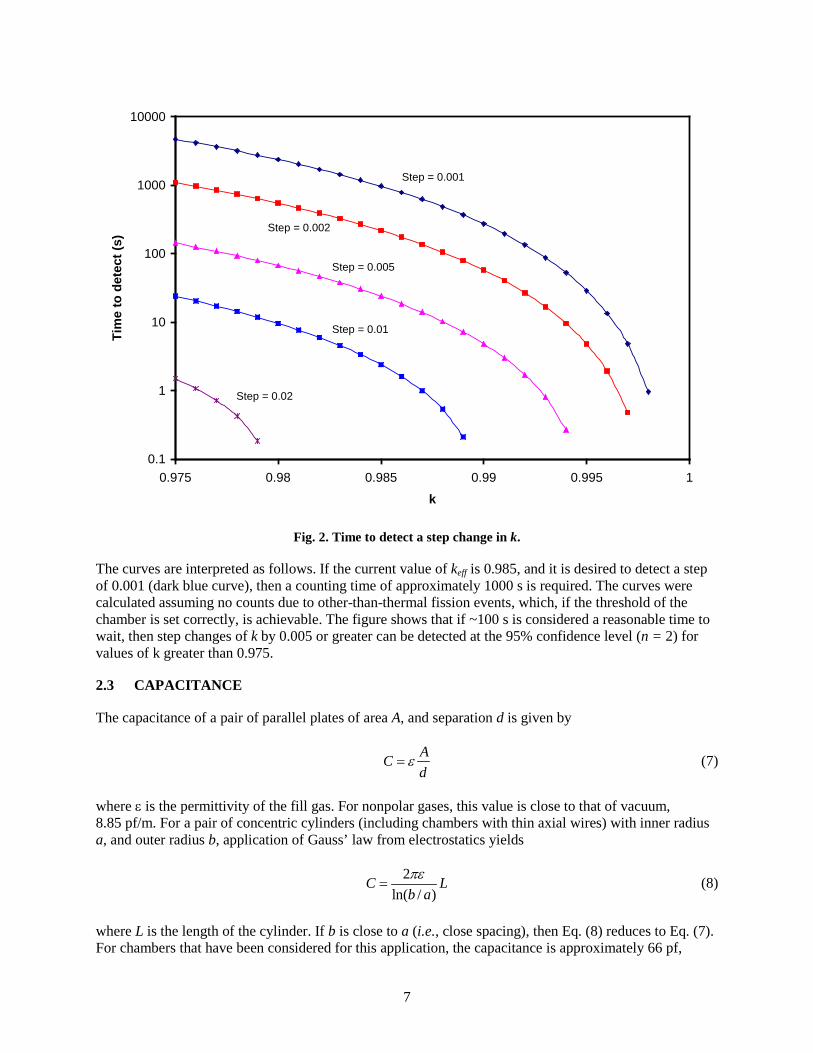
where k0 is the keff at startup, and ki is the keff at each rate. Level curves for this function with n = 2, k0 = 0.975, and k2 = k1 + δ are shown in Fig. 2. The figure shows the time needed to determine that a step change has occurred, given that the current value of keff is k.
7
Fig. 2. Time to detect a step change in k.
The curves are interpreted as follows. If the current value of keff is 0.985, and it is desired to detect a step of 0.001 (dark blue curve), then a counting time of approximately 1000 s is required. The curves were calculated assuming no counts due to other-than-thermal fission events, which, if the threshold of the chamber is set correctly, is achievable. The figure shows that if ~100 s is considered a reasonable time to wait, then step changes of k by 0.005 or greater can be detected at the 95% confidence level (n = 2) for values of k greater than 0.975.
2.3 CAPACITANCE
The capacitance of a pair of parallel plates of area A, and separation d is given by
ACd
ε= (7)
where ε is the permittivity of the fill gas. For nonpolar gases, this value is close to that of vacuum, 8.85 pf/m. For a pair of concentric cylinders (including chambers with thin axial wires) with inner radius a, and outer radius b, application of Gauss’ law from electrostatics yields
2ln( / )
C Lb aπε
= (8)
where L is the length of the cylinder. If b is close to a (i.e., close spacing), then Eq. (8) reduces to Eq. (7). For chambers that have been considered for this application, the capacitance is approximately 66 pf,
0.1
1
10
100
1000
10000
0.975 0.98 0.985 0.99 0.995 1
k
Tim
e to
det
ect (
s)
Step = 0.001
Step = 0.002
Step = 0.005
Step = 0.01
Step = 0.02
8
leading to a peak pulse voltages of 8 mV. The latter is inferred by knowing that the average energy to create an electron-ion pair in many gases is approximately 30 eV, and that fission fragments deposit up to 100 MeV.
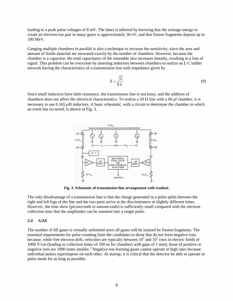
Ganging multiple chambers in parallel is also a technique to increase the sensitivity, since the area and amount of fissile material are increased exactly by the number of chambers. However, because the chamber is a capacitor, the total capacitance of the ensemble also increases linearly, resulting in a loss of signal. This problem can be overcome by inserting inductors between chambers to realize an L-C ladder network having the characteristics of a transmission line with impedance given by
LZC
= (9)
Since small inductors have little resistance, the transmission line is not lossy, and the addition of chambers does not affect the electrical characteristics. To realize a 50 Ω line with a 66 pf chamber, it is necessary to use 0.165 µH inductors. A basic schematic, with a circuit to determine the chamber in which an event has occurred, is shown in Fig. 3.
Fig. 3. Schematic of transmission line arrangement with readout.
The only disadvantage of a transmission line is that the charge generated in a pulse splits between the right and left legs of the line and the two parts arrive at the discriminators at slightly different times. However, the time skew (picoseconds to nanoseconds) is sufficiently small compared with the electron collection time that the amplitudes can be summed into a single pulse.
2.4 GAS
The number of fill gases is virtually unlimited since all gases will be ionized by fission fragments. The essential requirements for pulse counting limit the candidates to those that do not form negative ions because, while free electron drift, velocities are typically between 105 and 107 cm/s in electric fields of 1000 V/cm (leading to collection times of 100 ns for chambers with gaps of 1 mm); those of positive or negative ions are 1000 times smaller.2 Negative-ion-forming gases cannot operate at high rates because individual pulses superimpose on each other. At startup, it is critical that the detector be able to operate in pulse mode for as long as possible.

9
Argon is a common gas for use in fission chambers because the drift velocity3 at 1000 V/cm (a relatively easy field to reach) is ~ 4 × 105 cm/s (a reasonably large value), it is inert, relatively inexpensive, and the stopping power for ions is sufficiently large that only narrow separations are needed between the plates. The range of fragments in Kr and Xe is shorter, which leads to higher charge and signal if the spacing between the electrodes is smaller than the range. However, electron drift times in these gases are factors lower, and would result in a chamber with slower pulse response time for the same electric field. The choice of gas depends upon the overall design of the signal cabling and electronics, so optimization requires a system approach.
Additional gases are usually added to provide improved response. In proportional counters, quench gases such as methane or carbon dioxide are added to absorb ultraviolet light emitted from excited noble gases and to prevent electron avalanching. The electric fields in fission chambers are not sufficiently high to cause electron multiplication, so the quenching effect is not required. However, many of these quench gases also increase the electron mobility by a large factor. This allows the charge from each pulse to be collected quickly, enabling high count rates, and also increases the efficiency of charge collection.
A small proportion of nitrogen (< 1%) increases electron velocity substantially and is a gas of choice because it is relatively inert and does not lead to the deposition of conducting debris inside the chamber. Carbon-containing gases, as they undergo radiolysis, form long chain molecules, which eventually settle on the chamber walls, thus depleting the gas supply. In the worst case, elemental carbon is released to settle in the chamber and to provide unintended conducting paths.
Purity of gas is extremely important because the infiltration of even small quantities of electronegative molecules, such as oxygen, can rapidly render a chamber inoperable. Although sealing a chamber is relatively straightforward and will prevent infiltration, outgassing of chamber components is an issue affecting all chambers. Consequently, materials such as Mg ribbon, zeolites, and activated carbon may be included in the design to act as getters. Unfortunately, at 1073 K, Mg is molten, and carbon can react with nitrogen, as is shown in Sections 4.4 and 5.4.2, below. Therefore, it will be necessary to characterize carefully the volatile impurities in the structural materials and to bake out all materials that are inside the chamber.
Getters also immobilize chemically reactive fission fragments. Thus if no getter is included in the chamber, the fragments will build up over time. For a chamber containing 5 g of 235U, a maximum 2-year thermal fluence of 6×10²⁰ n/cm2 (1013 n/cm2/s, full power, for 2 years) incident over the 150 cm2 profile of the chamber, approximately 5% of the uranium will undergo fission. Most of the fission fragments will embed in or attach to the chamber walls, but it will be an object of investigation to determine how their presence will affect pulse shape and amplitude.
2.5 PRESSURE AND ELECTRIC FIELD
The motion of electrons in a gas is well described by a diffusion process in which the drift velocity is proportional to the reduced electric field, E/p, where p is the gas pressure. Knoll2 shows a plot of electron drift velocities as a function of reduced electric field in which it is seen that for many gases the proportionality is maintained over a wide range of reduced field. Since charge collection times decrease with increased drift velocity, it is desirable to maintain as high and as uniform an electric field as possible. It is also desirable to minimize the chamber’s response to electrons and alpha particles, indicating the need to maintain the electric field below that which permits multiplication. For typical gases, Knoll4 reports this field to be approximately 103 V/mm. For a chamber with a plate separation of 5 mm, a voltage of 500 V provides both a good safety margin (a factor of 10), a reasonable drift velocity5 (approximately 1.7×106 cm/s, computed for the electric field of 100 V/mm), and charge collection time of approximately 300 ns.

10
2.6 THERMAL LOADING
Based on the operation at 3𝗑1015 n/cm2/s of the High Flux Isotope Reactor at ORNL, a 1 kg in-core chamber in a neutron flux of 1013 n/cm2/s can reasonably expect to see a gamma heating of 133 W at full power. To calculate the i2R heating based on ionization current, the design sensitivity, 1 cps/nv, is used to estimate 1013 cps at 100% power, and it is assumed that each fission generates deposits 10 MeV in the gas (assumed to be Ar with an average ionization energy of 26 eV), leading to 3.85𝗑105 electrons and ions that traverse the potential difference between the plates. Although in pulse mode the chamber would operate with 500 V between the plates, this would be reduced at full power because the chamber would be operating in current mode and distinguishing individual pulses would no longer be necessary. Using 25 V as the maximum potential at full reactor power, and noting that both the ions and electrons contribute to the current, a heating rate of 31 W is obtained. Heating caused by the dissipation of fission-fragment kinetic energy in the chamber is estimated by multiplying the count rate at 100% power and the energy per fission (170 MeV, for uranium), to yield 270 W. For a 1 kg chamber, the total heating can be expected to be approximately 434 W.

11
3. DETECTOR ELECTRONICS
3.1 THEORY AND BACKGROUND
The fission chamber is, in essence, a gas detector operating in ionization or proportional mode. Radiation events generate charge proportional to their energy, and that charge is swept to a collection electrode by an electric field biasing the detector. Collection time for the charge is usually a few tens of nanoseconds so that, assuming the bias power supply on the detector can supply sufficient current, these detectors will operate at very high event rates. As an example, the expected basic operating ranges for the detector are presented6 in Fig. 4.
Source start-up range
Intermediate range
Power Range
101 103 >109107105
Fig. 4. Range of values of neutron flux (n/cm2/s) at the projected location of the detector.
With such an enormous range of potential event rates, it should be obvious that the information provided by the detector cannot be processed by a single type of readout electronics. Because of that, several techniques have been developed or adapted to deal with the wide dynamic range. These are typically employed together over a limited range of the detector operation. In this way, the entire range is covered.
To understand the concepts, we first need to introduce Campbell’s Theorem,7 which states:
A system whose input is a Poisson-distributed signal in time with a mean rate of λ and whose impulse response is h(t) has an output mean and variance given by
( )sV h t dtλ∞
−∞
= ∫ (10)
and
2 2 ( )s h t dtσ λ∞
−∞
= ∫ (11)
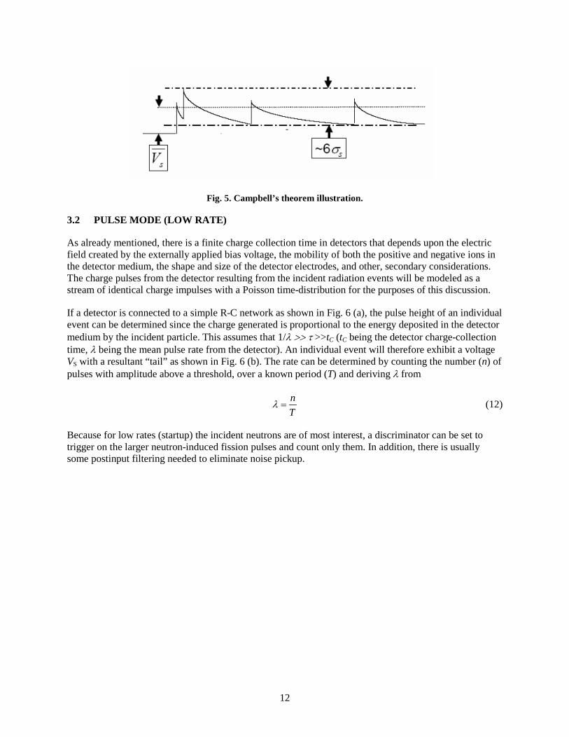
This is illustrated graphically in Fig. 5.
12
Fig. 5. Campbell’s theorem illustration.
3.2 PULSE MODE (LOW RATE)
As already mentioned, there is a finite charge collection time in detectors that depends upon the electric field created by the externally applied bias voltage, the mobility of both the positive and negative ions in the detector medium, the shape and size of the detector electrodes, and other, secondary considerations. The charge pulses from the detector resulting from the incident radiation events will be modeled as a stream of identical charge impulses with a Poisson time-distribution for the purposes of this discussion.
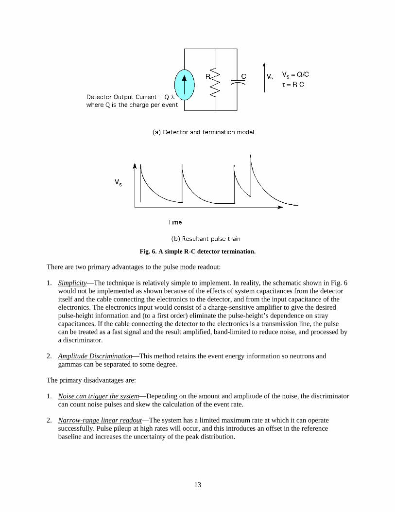
If a detector is connected to a simple R-C network as shown in Fig. 6 (a), the pulse height of an individual event can be determined since the charge generated is proportional to the energy deposited in the detector medium by the incident particle. This assumes that 1/λ >> τ >>tC (tC being the detector charge-collection time, λ being the mean pulse rate from the detector). An individual event will therefore exhibit a voltage VS with a resultant “tail” as shown in Fig. 6 (b). The rate can be determined by counting the number (n) of pulses with amplitude above a threshold, over a known period (T) and deriving λ from
nT
λ = (12)
Because for low rates (startup) the incident neutrons are of most interest, a discriminator can be set to trigger on the larger neutron-induced fission pulses and count only them. In addition, there is usually some postinput filtering needed to eliminate noise pickup.
13
Fig. 6. A simple R-C detector termination.
There are two primary advantages to the pulse mode readout:
1. Simplicity—The technique is relatively simple to implement. In reality, the schematic shown in Fig. 6 would not be implemented as shown because of the effects of system capacitances from the detector itself and the cable connecting the electronics to the detector, and from the input capacitance of the electronics. The electronics input would consist of a charge-sensitive amplifier to give the desired pulse-height information and (to a first order) eliminate the pulse-height’s dependence on stray capacitances. If the cable connecting the detector to the electronics is a transmission line, the pulse can be treated as a fast signal and the result amplified, band-limited to reduce noise, and processed by a discriminator.
2. Amplitude Discrimination—This method retains the event energy information so neutrons and gammas can be separated to some degree.
The primary disadvantages are:
1. Noise can trigger the system—Depending on the amount and amplitude of the noise, the discriminator can count noise pulses and skew the calculation of the event rate.
2. Narrow-range linear readout—The system has a limited maximum rate at which it can operate successfully. Pulse pileup at high rates will occur, and this introduces an offset in the reference baseline and increases the uncertainty of the peak distribution.

14
3.3 MEAN-SQUARE VOLTAGE MODE OR CAMPBELLING MODE (LOW-MEDIUM RATE)8
If we AC couple the pulse stream shown in Fig. 5, the remaining signal is proportional to the square root of the variance. We can then square and average that signal as shown in Fig. 7.
Fig. 7. Mean-square voltage (MSV) processing chain.
The output of this system is given by
2 2s Qσ λ∝ (13)
where Q is the amount of charge generated in a given event. The salient features of this result are that the output is still proportional to the average rate and that the output is now proportional to the square of the input signal amplitude.
The primary advantage of the MSV mode readout is improved energy separation because the output is proportional to the square of the input signal amplitude, and the difference in signal amplitude between gammas and neutrons is enhanced by the square of their ratio.
The primary disadvantages are:
1. Added complexity—The squaring circuit must operate at the expected bandwidth of the system. Some prefiltering of the input pulses is almost essential.
2. Narrow-range linear readout—Again, the output variable of interest is linearly related to the rate so the range will be limited.
3.4 CURRENT MODE (HIGH RATE)
At very high rates, it becomes increasingly difficult to maintain a filter impulse response with a time response sufficiently short that pulse counting would be practical or that nonlinear (squaring) circuits would operate reliably. Fortunately, the need to discriminate neutrons and gammas becomes almost moot in the power-range operating mode of the reactor so that most of the information can be discarded. This is the value of current mode.
If we revisit the system shown in Fig. 6, we can apply Campbell’s Theorem, and obtain, for the mean and variance,
( )t
sQV h t dt e dt Q R IRC
τλ λ λ∞
−
−∞
= = = =∫ ∫ (14)
Detector Squarer Averager
DC block

15
2
2 22( )
2sQh t dt
Cλτσ λ
∞
−∞
= =∫ (15)
The value of Qλ is simply the mean current from the detector so that the voltage across the resistor is proportional to the event rate in the detector. The variance can be minimized with proper low-pass filtering. It is interesting to note that at high rates (λτ >> 1) the Central Limit Theorem predicts that the output probability density will become Gaussian irrespective of the input density.9
The primary advantage of the Current Mode readout is:
1. Simplicity—This is essentially the measurement of a current. Proper filtering must be applied to minimize the effects of the signal variance.
The primary disadvantages are:
1. DC amplification needs to be stable—A large DC amplification may be needed and must be stable.
2. Narrow-range linear readout—Again, the output variable of interest is linearly related to the rate so the range will be limited.
3.5 EXTENDED-RANGE COUNTING (LOW-HIGH RATES)
Extended-range counting10 (ERC) is a technique that has its roots in pulse-mode counting. In short, it is a pulse-mode technique that utilizes a rate-sensitive discriminator threshold to allow traditional pulse mode at low rates but that increases the threshold as the rate increases to maintain a useful system.
Pulse-mode counting is grounded in the area of probability known as level-crossing problems. In general, for a normal process, the rate of crossings (any direction) across an arbitrary level a of a system whose impulse response is H(ω) and whose mean value is η can be shown to be
∫
−−
∞
∞−
∞
∞−
∞
∞−
∫
∫=Γ
ωω
η
ωω
ωωω
π
dH
a
a edH
dH 2
2
)(2
)(
2
22
*)(
)(1
(16)
Since there must be a positive crossing for each negative crossing, and we are interested in crossings in a single direction, the maximum rate of crossings of one type occurs when a = η and
∫
∫∞
∞−
∞
∞−=Γωω
ωωω
πdH
dH
2
22
max
)(
)(
21
(17)

16
is the maximum rate (for crossings in a single direction) that can be obtained. Using a variety of mathematical manipulations, we can obtain the output average rate of pulses that exceed the threshold a for a mean event rate of λ:
2
2
2
)(
max *),( QK
a
out ea λ
η
λ−
−
Γ=Γ (18)
where K is a constant derivable from H(ω) of the signal processing system and 2Q is the mean-squared charge from the detector.
Although the meaning of Eq. (18) is not immediately clear regarding an implementation for pulse counting, close inspection reveals that the output count rate from a system implementing this will (a) increase nonlinearly with an increase in input rate and (b) decrease nonlinearly with an increase in threshold voltage. If we allow the threshold to vary as some function of the input rate by inserting the threshold control in a feedback loop with the discriminator as shown in Fig. 8, we obtain a counting function valid above the rate that a fixed-threshold system would allow. The figure compares a fixed threshold that saturates above a normalized rate of 10, a threshold that varies over the entire counting range (continuous), and a threshold that varies only above a normalized input rate of approximately 0.2 (discontinuous). What should be clear from this is the fact that very high rates well above where pulse counting is normally used can be measured by this technique without switching measurement modes. In addition, there are actually two variables that can be measured. The output pulse rate is the obvious measure, but the threshold voltage is also varying with rate.
(a) (b)
Fig. 8. (a) Block diagram and (b) Normalized response.
The primary advantages of the ERC Mode readout are:
1. Large counting range without switching—The technique essentially allows an extension of pulse counting to rates well above the traditional limit. Additional information can be obtained from the variation of the threshold as rate increases.

17
2. Response can be tailored—The point at which the ERC feedback can be set to give higher sensitivity at low rates and reduced sensitivity at high rates.
The primary disadvantage is:
1. A more complicated system—The discriminator for this needs to have very good, low-amplitude, high-speed response. This is not a major hurdle but does require care in the choice/design of the discriminator.
3.6 LOGARITHMIC COUNTING (LOW-HIGH RATES)10,11
In the years since the ERC technique was developed, integrated-circuit technologies have come a very long way toward improved bandwidth and improved device performance. Because of this, the performance of circuits such as the logarithmic amplifier has increased dramatically. One of the drivers for this has been the optical-diode processing community, which has seen a need for increased speed and dynamic range. Logarithmic amplifiers are circuits whose voltage output is proportional to the natural log of the input current. The simplified circuit is illustrated in Fig. 9 as a trans-impedance amplifier with a logarithmic feedback element. If one adds a feedback capacitor across the feedback element, this looks exactly like a traditional charge-sensitive feedback preamplifier. The resulting circuitry effectively exhibits a very large feedback resistor at low pulse rates (no pileup) to an increasingly smaller resistor as the pulse rate increases (increasing pileup).
Fig. 9. Simple model of logarithmic processor.
Fig. 10 illustrates a simplified simulation of a single event superimposed on increasingly larger DC current, showing that as the DC current increases, the pulse amplitude becomes a smaller percentage of the overall DC level. This shows that, in concept, at low rates this technique should be able to be utilized as a pulse-counting circuit, and at higher rates, where pile up dominates, the DC level can be an indicator of count rate. This circuit could, in principle, be used to implement a pulse processor with only one single processing path.

18
Fig. 10. 2×10⁶ e-h pairs/event collected in 500 ns superimposed on DC current from 10-11 to 10-4 A.
As shown in Fig. 11, an implementation will consist of several blocks. We are assuming that the preamplifier and detector will be separated by the containment building, which would impose at least 25 m of cable between the two. The preamplifier would necessarily be resistively terminated in 100 Ω and would either be a separate preamplifier or integrated as part of the logarithmic processor. The processor would provide two outputs. One would go to a pulse-counting circuit that would operate at low rates while individual pulses are distinguishable. As the rate increases, the output should become a continuum of pulses and be treated as a varying output voltage, logarithmically proportional to the input count rate. This would then be input to a DC measurement system.
Fig. 11. Notional pulse processing system using a logarithmic processor.

19
3.7 EFFECTS OF CABLES ON THE METHODS12
We are, for the sake of simplicity, going to assume that the connection of the fission chamber to the measurement electronics will be accomplished by using a terminated transmission line. The termination may consist of passive resistors or active amplifiers, but the line will be matched in its characteristic impedance. It must be remembered that any change in h(t) whether it comes from changes in the detector, cable, or electronics will have an effect on the transfer functions presented thus far. In order to maintain calibration, the entire system needs to remain time and temperature invariant.
The canonical model of a coaxial transmission line is shown in Fig. 12. If we assume resistance R = 0 and conductance G = 0, the characteristic impedance of the ideal line is defined as
0LZC
=
where L is the self-inductance per unit length and C is the capacitance per unit length between the center conductor and the shield. It must be emphasized that the model in Fig. 12 shows lumped element equivalents of what are actually distributed elements.
L R
CG
Fig. 12. Canonical transmission line model.
The value of L depends primarily on the diameter of the wire and the magnetic permeability of the medium surrounding it. The capacitance depends on the spacing of the wire from the shield and on the dielectric constant of the material between them. Since the permeability of most candidate dielectrics are close to that of vacuum, heat and radiation will likely not have much of an impact if any on the inductance of the cable. The more likely impact will be on the capacitance through a change in the dielectric constant or spacing of the wire to the shield with time.
The more serious concern is that of the change in the cable loss mechanisms, R (in ohms) and G (in siemens). R comes about from both the conductivity of the center conductor and the frequency-dependant nature of the cross-sectional area through which current flows (skin effect). The skin effect can be mitigated by coating the surface of the center wire with a highly conductive layer that has minimum change in conductivity with heat and radiation. The conductance G arises from dielectric losses and is likely the biggest potential problem for these systems. Decrease in G can give rise to noise and cable loss but is entirely a function of the dielectric and its interface with the surrounding metals.
The primary effects on nuclear measurement systems can be categorized as follows:
1. L or C changes so as to change Z0—Frequencies in the pulses whose wavelength approaches that of the cable length will be partially reflected. This will result in a loss of signal at the amplifier and pulse
20
pileup due to the reflections because of the signal being re-reflected at the detector. A lossy cable actually helps this somewhat because the reflections must travel twice more over the cable to be reprocessed by the amplifier and may be sufficiently attenuated not to pose a problem.
2. R increases—This will increase the propagation loss as a proportion of the length. It will also increase dispersion (velocity of propagation of higher-frequency components of the waveform are slower than that of the lower-frequency components) which could, in the extreme, introduce pulse distortion.
3. G decreases—This could increase noise and possibly leakage. This would have the worst effect on the current mode readout.
All of these comments apply to triaxial cable as well as to coaxial cable. The extra shield in the triaxial cable likely will provide enhanced protection from externally-radiated noise; the added dielectric would likely have no other effect.
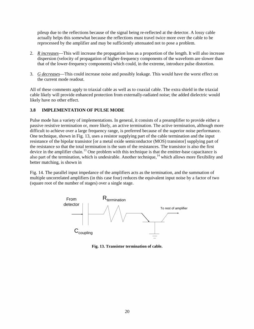
3.8 IMPLEMENTATION OF PULSE MODE
Pulse mode has a variety of implementations. In general, it consists of a preamplifier to provide either a passive resistive termination or, more likely, an active termination. The active termination, although more difficult to achieve over a large frequency range, is preferred because of the superior noise performance. One technique, shown in Fig. 13, uses a resistor supplying part of the cable termination and the input resistance of the bipolar transistor [or a metal oxide semiconductor (MOS) transistor] supplying part of the resistance so that the total termination is the sum of the resistances. The transistor is also the first device in the amplifier chain.13 One problem with this technique is that the emitter-base capacitance is also part of the termination, which is undesirable. Another technique,14 which allows more flexibility and better matching, is shown in
Fig. 14. The parallel input impedance of the amplifiers acts as the termination, and the summation of multiple uncorrelated amplifiers (in this case four) reduces the equivalent input noise by a factor of two (square root of the number of stages) over a single stage.
Fig. 13. Transistor termination of cable.
Rtermination
Ccoupling
Fromdetector
To rest of amplifier

21
Fig. 14. Parallel input technique.
Fig. 15 illustrates an entire system for pulse counting.15 This Hanford system includes not only the Oak Ridge National Laboratory (ORNL) preamplifier for termination but also the discriminator and ratemeter. This system was designed for data acquisition and not for operation. A modern system would not, for example, use an X-Y recorder or the sweep function. The single-channel analyzer (SCA) might be used or directly replaced with a discriminator.
Fig. 15. Pulse-counting system.
3.9 MEAN-SQUARE VOLTAGE MODE OR CAMPBELLING MODE
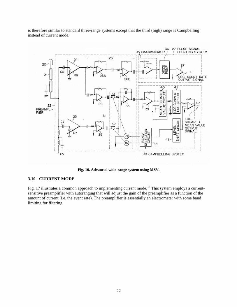
Fig. 16 illustrates an advanced system that utilizes both pulse mode counting for low rates and a ranging system for the MSV portion of the circuitry that extends the counting range.16 This system takes the log of the MSV value at high rates but can switch to a different bandwidth amplifier for the very highest rates. It
22
is therefore similar to standard three-range systems except that the third (high) range is Campbelling instead of current mode.
Fig. 16. Advanced wide-range system using MSV.
3.10 CURRENT MODE
Fig. 17 illustrates a common approach to implementing current mode.17 This system employs a current-sensitive preamplifier with autoranging that will adjust the gain of the preamplifier as a function of the amount of current (i.e. the event rate). The preamplifier is essentially an electrometer with some band limiting for filtering.

23
Fig. 17. Autoranging current-mode system.

24
4. URANIUM COATINGS
4.1 CHOICE OF FISSILE MATERIAL
Uranium metal, uranium oxide, uranium carbide, and uranium nitride have been considered as the fissile material used for the surface coatings in the fission chamber. Uranium metal readily reacts with air to form the oxide and nitride. Uranium carbides and nitrides react with water and at elevated temperatures form the oxide in the presence of oxygen. In a mixed inert gas–nitrogen atmosphere, often used in these detectors, thermodynamic calculations indicate that the uranium oxide is stable at 1073 K. If proper precautions are undertaken to prevent exposure to ambient air, the nitride may exhibit similar stability. However, at 1273 K and with equilibrium constants smaller than 10-55, the oxide will not convert to the nitride in a 10% nitrogen environment (inert gas balance). This corresponds to the following reactions:
2 𝑈𝑂2 + 𝑁2(𝑔) → 2 𝑈𝑁 + 2 𝑂2(𝑔) 𝑈3𝑂8 + 1.5 𝑁2(𝑔) → 3 𝑈𝑁 + 4 𝑂2(𝑔)
Uranium oxides are potentially more stable at 1273 K, according to phase stability diagrams (Fig. 18); however, uranium nitrides exhibit higher conductivities than the oxides. This conductivity is a useful feature because the fissile material can assist the charge conduction more effectively as the nitride than as the oxide.
Fig. 18. U-O-N phase diagram at 1273 K. Pressures are expressed in atmospheres.
Fig. 18 illustrates that under the operating conditions (1%–10% N2, inert gas balance), the system will be near the U4O9/U3O8 border if part-per-million levels of oxygen are present. This suggests a phase change may occur during thermal cycling. Due to this (1) the gases must be pure and oxygen free if the nitride is utilized and (2) if oxygen is present, thermal cycling will need to be studied to understand the effect of film adhesion for the oxide (or nitride) films.
30 20 10 -10 -20 -30 -40 -50
60
50
40
30
20
10
0
-20
-30
log pO2(g)
log
pN2(g
)
U
UN
UN1.73
U2N3 UO2
UO3
U3O
8 U
4O9
UO2(NO3)2

25
Uranium nitride presents the intriguing possibility of having a more conductive fissile material on the base metal. In addition to this, a higher density of uranium exists, resulting in less fissile material required for similar responses. The use of the nitride over the oxide presents a significant challenge due to the air sensitivity because of nitride-to-oxide conversion under ambient conditions. Storage of the fissile materials and assembly of the fission counter in an inert atmosphere should mitigate this challenge. The nitride can be formed through annealing in an ammonia atmosphere at high temperatures (> 773 K). This high-temperature annealing will serve the dual purpose of fixing the uranium nitride on the base metal, thereby increasing the thermal cycling endurance, while setting the phase of the uranium nitride.
The nitride exists in three predominant phases: UN2, U2N3, and UN. The dinitride decomposes at approximately 1073 K to form U2N3 and evolves nitrogen gas (N2). U2N3 can be converted to UN at high temperatures under an ammonia (NH3) atmosphere. Thermally annealing U2N3 in a nitrogen atmosphere is not sufficient for full conversion at 1073 K (although some conversion does occur, nitrogen gas is not sufficiently reactive to convert the oxide to the nitride).
4.2 METHODS OF ATTACHMENT
Methods of attachment of uranium oxide to a metal surface are varied, including chemical vapor deposition (CVD), pulsed-laser ablation (PLA), sputtering, and electrodeposition. Electrodeposition, as the most commonly employed method, is the method of choice due to the ease of producing uniform coatings and coating the interior of tubular materials after proper surface preparation. However, if significant adhesion issues arise with electrodeposition, it may be necessary to employ one of the other methods. PLA has been used in the coating of fuel rods for nuclear reactors, so it remains an option.
4.3 DESCRIPTION OF ELECTRODEPOSITION
The electrodeposition process begins with proper surface treatment. Without proper surface pretreatment, the adhesion can be severely hampered. The base material must be cleaned electrochemically by immersing the material in a hot (~373 K) acid bath. Following the acid bath, the metal is washed and stored in distilled water. The material is then electropolished in an acidic solution (H2O/H3PO4/H2SO4) under a reverse (anodic) current. This is again followed by washing and storage in distilled water. Ideally, this process will occur immediately prior to electrodeposition to prevent oxidation and/or nitriding of the base material, which can deleteriously affect the adhesion of the uranium layer.
The electrodeposition of uranium oxide proceeds with a uranyl nitrate solution that has been fumed with sulfuric acid. The resulting solution is buffered to an acidic pH (between 2 and 3) to form the electrodeposition solution. This electrodeposition solution is then added to the electrochemical cell containing the base material (cathode) and a counter electrode (anode). A DC current is applied (< 1 A) to fix UO2
2+ on the base metal. Following plating, the metal is rinsed with ethanol at pH 8 and cured briefly at high temperature to form the air-stable oxide. The thickness of the uranium layer coated onto the base metal is proportional to the length of time utilized in the deposition process.
To electrodeposit the uranium nitride, Pourbaix diagrams suggest switching to a nitrogen-rich solution such as a dilute ammonium nitrate solution at acidic pH (between 2 and 3) instead of sulfuric acid will provide the nitride. The high-temperature curing will be performed in either ammonia or an ammonia/nitrogen mixture to force the nitriding of any oxide present. The electrodeposited material will be stored under argon to prevent oxidation.
Clearly, the choice of base metal will be influenced by the interaction with water and acids during the electrodeposition step as well as the reactive atmosphere (NH3) during nitriding and annealing. Based on their chemistry, molybdenum, alloys of platinum and alloys of other noble metals, aluminum, stainless

26
steel, and inconels are not expected to be affected by plating baths. The last three metals are presently used in the fabrication of fission chambers. Platinum and other noble metals are not preferred materials in this application because their high thermal neutron absorption cross sections will seriously degrade the sensitivity of the chamber. Aluminum cannot be used because its melting point is below the required operating temperature of the chamber.
4.4 FAILURE MECHANISMS
Surface adhesion is the primary mode of failure. This is influenced by the surface condition of the base metal prior to electrodeposition as well as the effect of heating the base metal in an ammonia atmosphere at high temperatures. The surface adhesion is also under scrutiny if brazing is the technique utilized to seal the inner chamber after assembly. The brazing temperature will need to be lower than 1393 K if U2N3 is present to prevent an α→β-U2N3 phase change. This phase change can also affect the adhesion. Based on the tubular design, electropolishing is the best way to prepare the surface for deposition.
Incompatibility between the base metal and the uranium deposition over time could cause adhesion issues. This includes radiation effects at grain boundaries of the base metal and between the base metal and the uranium film. Currently, it is not known how the coating will behave over time. Literature on lower-temperature fission chambers suggest that the coating will be sufficient; however, no such data exist for 1073 K over an extended amount of time. A series of experiments utilizing coupons of the base metal to which uranium has been deposited must be cycled in an appropriate atmosphere and at working temperatures to determine the stability of the uranium nitride coatings.
The “getter” is a high-surface-area material added to the fission chamber to adsorb any off-gassed matter or fission products that may compromise the electronics of the fission chamber. The material must either be nonconductive or not form dust that could electrically bridge the components of the sealed fission chamber. Activated carbon, while possessing high surface areas, is conductive and typically a powder. Binders have been used to pelletize the activated carbon powders; however, these organic polymeric binders do not exhibit the thermal stability required for this application. Solid chunk activated carbon is a viable alternative provided the particle size is sufficient to prevent spalling of fine particulate that would bridge the electrical components, resulting in a short state. High-surface-area activated carbon fabrics represent one alternative as the fabrics exhibit superior strength and generate no dust over time with agitation. The fabrics are typically prepared by the carbonization of Rayon fabric under inert atmospheres followed by oxidative activation by steam or carbon dioxide (CO2). These materials are commercially available. The adsorptive properties are suspect at 1073 K; however, as little adsorption data exist at the operating temperatures of this project. Tests with actual samples will be necessary to understand the high-temperature adsorptive properties of the activated carbon fabrics.
Zeolite materials represent the alternative to activated carbons. Zeolites will exhibit some conductivity at 1073 K but below the level of the activated carbon materials. While many zeolites are powdered materials, alumina binders are often utilized to pelletize the zeolite. This is the method used by Zeolyst International with their Zeolite-Y product. The main question regarding the zeolite materials involves the stability of the porosity at elevated temperatures. Discussions with Zeolyst International representatives indicate that Zeolite-Y, with a silicon-to-aluminum ratio (Si:Al) of 2.5 is stable at 1073 K but not necessarily at 1273 K. This is important due to the option of brazing as the method to seal the inner container, which must be performed above the operating temperature to prevent failure. Two other siliceous zeolites, with the BEA and MFI structure exhibit stability at 1073 K but with reduced stability at 1273 K, may occur. This application is of the nonstandard form for zeolites and pushes the envelope for zeolite use. Metal-doped cationic zeolites, such as a zeolite doped with silver may increase the adsorptive properties for fission products such as iodine; however, the stability is not known and the known patent18 to suggest silver-zeolites are stable at these temperatures does not provide conclusive proof. Studies of

27
these zeolitic systems at high temperatures are warranted (1) to determine the viability of zeolites for this application and (2) to fill in an important gap in zeolite information for the community, thus possibly opening up zeolites for use in other high-temperature applications.

28
5. CHAMBER DESIGN
5.1 METALS
The primary areas of concern for structural materials selection include materials strength at temperature; radiation-induced property changes; thermal stability; and chemical compatibility with the chamber atmosphere, uranium-bearing layer, and liquid salt coolant. Radiation induced property changes vary with the alloy type but can include embrittlement through either dislocation loop and cluster formation, void swelling, radiation-induced segregation of solute or He to grain boundaries, and radiation induced changes to precipitates. Further concerns on materials selection include commercial availability, the capability to fabricate or form the material into components, and the joining of the material to other parts.
An illustration of the approximate upper temperature limits, based on 104 h creep rupture data, of different materials systems is shown in Fig. 19.19 Combining the upper temperature limitations based on thermal creep considerations and lower temperature limitations based on radiation damage, a simple assessment of various materials systems is presented in Fig. 20.20 Dark bands represent operating range; the lightly shaded bands represent uncertainties in the upper and lower temperature limits. As can be seen from these simple plots, a number of ideal candidates that have substantial radiation and corrosion effects databases fall short of the 1073 K operating temperature of the fission chamber.
Fig. 19. Summary of creep rupture performance illustrating upper
temperature limits of various materials systems, after [19].

29
Fig. 20. Operating temperature windows for various alloy types.
5.1.1 Stainless Steel and Ferritic Oxide-Dispersion-Strengthened Steels
Stainless steels, which have the largest irradiation and chemical compatibility database and have shown dramatic strength increases over the past decades through chemistry modifications (alloys D9, HT-UPS and NF709), have upper temperature limits of 823 to 873 K for ferritic/martensitic (F/M) steels and 973 to 1073 K for austenitic 304 and 316 grades. These temperature limits are at or below the nominal temperature for the fission chamber. While the current ASME Subsection NH21 provides guidance for nuclear reactor structural components and gives a primary stress limit temperature for 304 and 316 grades at 1089 K for 300,000 h or less, it does not fully account for environmental effects, nor does it clearly specify stress levels. Furthermore, if there is the potential for limited or extended service at temperatures >1073 K, austenitic steels would no longer be a valid candidate for the chamber structure.
An illustration of the design stress vs temperature plot of allowable operating limits for type 316LN grade based on extensive experimental tensile and thermal creep data, derived by Zinkle et al.22 is shown in Fig. 21. The operating limits are bounded by the creep rupture data above 820 K for an allowable design stress of 2/3 rupture stress over a 10 year lifetime and 1/3 ultimate tensile strength at lower temperatures. Using this conservative approach, in that creep rupture data for 10 years was taken, austenitic steel would not be a suitable candidate.

30
Fig. 21. The design stress vs temperature of allowable operating
limits for 316LN grade stainless.
Improving high-temperature mechanical strength of stainless steel through oxide dispersion strengthening may provide a means of obtaining a structural component with suitable properties for the fission chamber. Produced through mechanical alloying (MA), a powder-processing method followed by consolidation steps typically through hot extrusion, the ferritic MA-956 (Fe-20Cr-0.5Ti-4.5Al-0.05C-0.5Y2O3) and MA957 (Fe-14Cr-1Ti-0.3Mo-0.25Y2O3) alloys incorporate small, uniformly distributed Y2O3 particles throughout the microstructure. In comparison to the 316LN-operating window (Fig. 21), the addition of Y2O3 particles increases the operating range for MA-946 (Fig. 22) through increased tensile strength and in strength retention at elevated temperatures. The MA-956 alloy was first developed for aerospace applications but is now used commercially for a range of industrial applications for prolonged high-temperature operations at 1372 K.23 The small addition of aluminum creates a passivation layer to further oxidation as well as a barrier to carburization. However, the compatibility of MA-956 or MA-957 with the fission chamber gas will form a nitride layer that will deplete the concentration of nitrogen inside the chamber and affect the signal-response properties of the chamber.

31
Fig. 22. The design stress vs temperature of allowable operating
limits for oxide-dispersion-strengthened MA-956 oxide-dispersion-strengthened austenitic stainless steel.24
Very little data on compatibility of oxide-dispersion-strengthened (ODS) ferritic steels with liquid metal exist, with the bulk of data concerning liquid Na.24,25.A generalized overview of the Li compatibility of different materials classes is illustrated in Fig. 23.26 Ferritic chrome steels show good compatibility with Li-based salts up to temperatures near that of the fission chamber. However, data are limited for the conditions of interest, with most compatibility data limited to temperatures below 873 K. Compatibility of ODS steel with Li and Pb-17Li24 performed at temperatures up to 873 K showed corrosion rates more resistant than standard 316 grade. Linear weight loss with time suggests that corrosion was controlled through dissolution of the constituents rather than by impurity or solid reaction products, as confirmed by the indicated depletion of Cr. Compatibility with liquid metal at higher temperatures may be further compromised by the presence of Al in MA-956,27 with recommendations suggesting that the Al level should be reduced to below 1%.28
The role of Al on the liquid metal corrosion of MA-956 and comparable model ODS ferritic alloys was elucidated by El-Dasher and coworkers.29 In static corrosion testing between temperatures of 873 K and 1173 K in LiF-NaF-Kf molten fluoride salt, it was determined through electrochemical impedance spectroscopy that AlF3 was quick to form on the ODS ferritic alloys, and unlike CrF2, bonds to the surface of the samples to provide a corrosion inhibitor between 873 and 1073 K, but was rapidly lost at 1173 K. Further comparison of MA-956 to the model ODS ferritic alloys, showed that reducing Cr and Si concentrations, while adding W, improved corrosion response to the molten fluoride salt. The MA-957 alloy with less Cr and Ti instead of Al may be a better choice over MA-956 alloys.
A relatively mature database on stainless steel compatibility with UN, UO2 and UZrH exists and has been reviewed by Zinkle et al.22 for fuel considerations for space reactor applications. Furthermore, 316 stainless and advanced austenitic grades such as D-9-clad UO2 have been extensively studied in liquid metal fast breeder reactor experiments.30,31,32 The maximum cladding temperature for these experiments was reported at 1003 K due to the creep strength of the non-ODS stainless steel grades rather than any fuel-cladding interaction concerns.

32
Fig. 23. Liquid Li compatibility of various structural materials, from [26].
While austenitic steel can show significant radiation-induced swelling, this mainly occurs between temperatures of 623 to 873 K, with peak swelling near 773 K for high-dose-rate applications (10-6 to 10-7 dpa/s) and at lower temperatures for lower dose rates.25,33 FM steels show less swelling response because microstructural control is used to limit void formation. For the fission chamber conditions, swelling is not expected to be a concern for the ferritic ODS-stainless steels based on both temperature and the relatively low fluences. Furthermore, helium (He) generation, which is typical in Ni-containing austenitic grades and can lead to grain boundary embrittlement and reduced creep rupture strength,34,35,36 is not as significant an issue for MA-956 or MA-957 with Ni levels ≤ 0.1%. However, the He generation from B impurities, as well as any void swelling can be mitigated in the ODS microstructure through trapping at the nanoparticle interfaces that act as sinks for defect annihilation.34 This has been shown to be very effective in MA-956 irradiated to 200 dpa at 693 K, where void swelling was maintained to 1%.37
Areas of further work require a more thorough experimental assessment of ODS-ferritic MA-956 or MA-957 compatibility with liquid Li and high-temperature creep strength. For the envisioned low radiation doses expected for the fission chamber, He generation may not present a problem. Generally, He embrittlement can occur above He concentrations as low as 10 appm, which may require 1 dpa irradiation to achieve. However, He embrittlement sensitivity increases with temperature and applied stress acting on

33
the material. With the fission chamber being near the upper limit of ODS ferritic steels, an assessment of He generation for the relevant chamber conditions should be made.
5.1.2 Refractory Metal Alloys
The elevated operating temperatures envisioned for the fission chamber make the use of refractory metal alloys attractive for the structural components. However, the sensitivity of body-centered cubic refractory metal alloys to displacement damage from radiation and subsequent radiation induced embrittlement at temperatures ≤0.3Tm eliminates a number of possible candidates. While advances in low-carbon arc-cast molybdenum, ODS, and dilute Mo-base alloys incorporating refinements in chemistry and grain structure (size and morphology) offer impressive lower-temperature irradiated properties over standard Mo and TZM (Mo–0.5%Ti–0.1%Zr) grades,38,39 the 1073 K operating temperature for the fission chamber is still low for Mo-, Ta-, and W-base refractories. The allowable operating window for Mo is shown in Fig. 2424.
Fig. 24. Operating limits for pure molybdenum bound by strength and
creep limits, recrystallization temperature and low temperature radiation embrittlement.
Developed for improved low-temperature ductility and weld characteristics, Mo-Re alloys show a high degree of radiation hardening at temperatures less than 1073 K, resulting in reported embrittlement.39 Radiation-induced segregation (RIS) appears to be a significant problem associated with Mo-Re alloys, particularly in the 853–1430 K range, resulting in the nucleation of phases that are rich in Re and Os (transmutation products) in the microstructure, leading to reduced ductility. The low-temperature embrittlement of Mo and Mo-base alloys at temperatures of 1073 K and below are a concern for the structural integrity of the fission chamber and are not recommended candidate alloys.
While not normally associated with refractory metal alloys due to its lower melting temperature, V-4Cr-4Ti offers a well-documented radiation database, including corrosion and limited compatibility studies.40 The upper operating temperature for this material is limited to ~973 K due to thermal creep. However, an accurate assessment of the upper temperature range is limited based on short-term creep data.

34
Niobium and Nb-base alloys are the only refractory metal alloys that can be considered as a possible candidate for the fission chamber application. The only two commercially produced Nb-base alloys are C-103 (Nb-10Hf-1Ti) and Nb-1Zr. Very little irradiated materials property and compatibility data exist for C-103. While C-103 offers a significant increase in tensile strength below 1273 K, its high-temperature mechanical properties, particularly creep, are no better than those of Nb-1Zr.41 Extensively studied for various space reactor programs, Nb-1Zr has a relatively more mature database than other refractory metal alloys. The possible use of liquid metal salts as coolant in the fission chamber design favors the use of Nb-1Zr over pure Nb, in addition to the improved strength at temperature. The use of Nb-1Zr, particularly in radiation environments, is strongly governed by the interstitial contamination content of the material, which limits ductility through the precipitation of Zr-rich precipitates (generally ZrO2) along grain boundaries (affecting mechanical and corrosion properties). Furthermore, the use of Nb-1Zr below 973 K is severely restricted by radiation-induced hardening that reduces the uniform elongation (total elongation values remain > 10% at temperatures below 1273 K). The operating window for Nb-1Zr is shown in Fig. 25; the effects of irradiation on the loss of ductility is shown in Fig. 26. Irradiated data represented by solid symbols and unirradiated by open symbols.42
Fig. 25. The design stress versus temperature of allowable operating limits for
Nb-1Zr24.
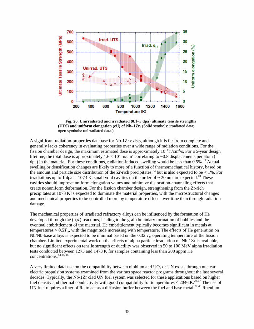
35
Fig. 26. Unirradiated and irradiated (0.1–5 dpa) ultimate tensile strengths
(UTS) and uniform elongation (eU) of Nb–1Zr. (Solid symbols: irradiated data; open symbols: unirradiated data.)
A significant radiation-properties database for Nb-1Zr exists, although it is far from complete and generally lacks coherency in evaluating properties over a wide range of radiation conditions. For the fission chamber design, the maximum estimated dose is approximately 1013 n/cm2/s. For a 5-year design lifetime, the total dose is approximately 1.6 × 10²¹ n/cm2 correlating to ~0.8 displacements per atom ( dpa) in the material. For these conditions, radiation-induced swelling would be less than 0.5%.39 Actual swelling or densification changes are likely to more of a function of thermomechanical history, based on the amount and particle size distribution of the Zr-rich precipitates,43 but is also expected to be < 1%. For irradiations up to 1 dpa at 1073 K, small void cavities on the order of ~ 20 nm are expected.43 These cavities should improve uniform elongation values and minimize dislocation-channeling effects that create nonuniform deformation. For the fission chamber design, strengthening from the Zr-rich precipitates at 1073 K is expected to dominate the material properties, with the microstructural changes and mechanical properties to be controlled more by temperature effects over time than through radiation damage.
The mechanical properties of irradiated refractory alloys can be influenced by the formation of He developed through the (n,α) reactions, leading to the grain boundary formation of bubbles and the eventual embrittlement of the material. He embrittlement typically becomes significant in metals at temperatures > 0.5Tm, with the magnitude increasing with temperature. The effects of He generation on Nb/Nb-base alloys is expected to be minimal based on the 0.32 Tm operating temperature of the fission chamber. Limited experimental work on the effects of alpha particle irradiation on Nb-1Zr is available, but no significant effects on tensile strength of ductility was observed in 50 to 100 MeV alpha irradiation tests conducted between 1273 and 1473 K for samples containing less than 200 appm He concentrations.44,45,46
A very limited database on the compatibility between niobium and UO2 or UN exists through nuclear electric propulsion systems examined from the various space reactor programs throughout the last several decades. Typically, the Nb-1Zr clad UN fuel system was selected for these applications based on higher fuel density and thermal conductivity with good compatibility for temperatures < 2046 K.22,47 The use of UN fuel requires a liner of Re to act as a diffusion buffer between the fuel and base metal.22,48 Rhenium
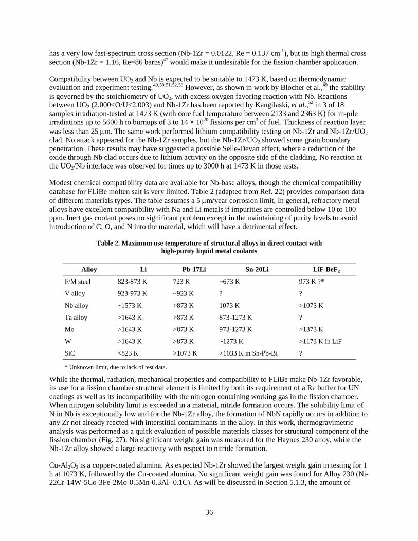
36
has a very low fast-spectrum cross section (Nb-1Zr = 0.0122, Re = 0.137 cm-1), but its high thermal cross section (Nb-1Zr = 1.16, Re=86 barns)47 would make it undesirable for the fission chamber application.
Compatibility between UO2 and Nb is expected to be suitable to 1473 K, based on thermodynamic evaluation and experiment testing.49,50,51,52,53 However, as shown in work by Blocher et al.,49 the stability is governed by the stoichiometry of UO2, with excess oxygen favoring reaction with Nb. Reactions between UO2 (2.000<O/U<2.003) and Nb-1Zr has been reported by Kangilaski, et al.,52 in 3 of 18 samples irradiation-tested at 1473 K (with core fuel temperature between 2133 and 2363 K) for in-pile irradiations up to 5600 h to burnups of 3 to 14 × 1020 fissions per cm3 of fuel. Thickness of reaction layer was less than 25 µm. The same work performed lithium compatibility testing on Nb-1Zr and Nb-1Zr/UO2 clad. No attack appeared for the Nb-1Zr samples, but the Nb-1Zr/UO2 showed some grain boundary penetration. These results may have suggested a possible Selle-Devan effect, where a reduction of the oxide through Nb clad occurs due to lithium activity on the opposite side of the cladding. No reaction at the UO2/Nb interface was observed for times up to 3000 h at 1473 K in those tests.
Modest chemical compatibility data are available for Nb-base alloys, though the chemical compatibility database for FLiBe molten salt is very limited. Table 2 (adapted from Ref. 22) provides comparison data of different materials types. The table assumes a 5 µm/year corrosion limit, In general, refractory metal alloys have excellent compatibility with Na and Li metals if impurities are controlled below 10 to 100 ppm. Inert gas coolant poses no significant problem except in the maintaining of purity levels to avoid introduction of C, O, and N into the material, which will have a detrimental effect.
Table 2. Maximum use temperature of structural alloys in direct contact with high-purity liquid metal coolants
Alloy Li Pb-17Li Sn-20Li LiF-BeF2
F/M steel 823-873 K 723 K ~673 K 973 K ?*
V alloy 923-973 K ~923 K ? ?
Nb alloy ~1573 K >873 K 1073 K >1073 K
Ta alloy >1643 K >873 K 873-1273 K ?
Mo >1643 K >873 K 973-1273 K >1373 K
W >1643 K >873 K ~1273 K >1173 K in LiF
SiC <823 K >1073 K >1033 K in Sn-Pb-Bi ?
* Unknown limit, due to lack of test data.
While the thermal, radiation, mechanical properties and compatibility to FLiBe make Nb-1Zr favorable, its use for a fission chamber structural element is limited by both its requirement of a Re buffer for UN coatings as well as its incompatibility with the nitrogen containing working gas in the fission chamber. When nitrogen solubility limit is exceeded in a material, nitride formation occurs. The solubility limit of N in Nb is exceptionally low and for the Nb-1Zr alloy, the formation of NbN rapidly occurs in addition to any Zr not already reacted with interstitial contaminants in the alloy. In this work, thermogravimetric analysis was performed as a quick evaluation of possible materials classes for structural component of the fission chamber (Fig. 27). No significant weight gain was measured for the Haynes 230 alloy, while the Nb-1Zr alloy showed a large reactivity with respect to nitride formation.
Cu-Al2O3 is a copper-coated alumina. As expected Nb-1Zr showed the largest weight gain in testing for 1 h at 1073 K, followed by the Cu-coated alumina. No significant weight gain was found for Alloy 230 (Ni-22Cr-14W-5Co-3Fe-2Mo-0.5Mn-0.3Al- 0.1C). As will be discussed in Section 5.1.3, the amount of

37
nitrogen absorbed and the depth of internal nitridation occurring in Ni-base alloys strongly depends on the alloying content. For Nb-1Zr to be suitable for use in the nitrogen atmosphere of the fission chamber a Recoating would have to be applied to the surface, which will reduce the performance of the fission chamber.
Fig. 27. Weight change after 1 h at 1073 K of different materials
measured through thermogravimetric analysis.
5.1.3 Ni-base Alloys
The use Ni-base superalloys in nuclear environments has generally been restricted to the lower fluence areas of terrestrial light water reactors. While focused research was directed at these alloys for advanced cladding and duct materials for the US Liquid Metal Fast Breeder Reactor Program in the late 1970s,54 radiation-induced grain boundary embrittlement in postirradiation tensile tests led to the abandonment of these alloys in favor of reduced-swelling forms of austenitic and ferritic/martensitic steels.
Superalloys can be classified into precipitate-strengthened and solid-solution alloys. The former achieve their strength through the presence of γʹ and γʺ precipitates in their structure that act as effective barriers to dislocation movement. The second type can use a combination of solid-solution strengthening and carbide strengthening, while carbide formation in precipitate or age-hardenable grades also occurs.
The effect of radiation on superalloy properties, like nearly all metallic alloys, can be categorized by low-, medium-, and high-temperature irradiation regimes. Below 673 K, the radiation damage in the microstructure is dominated by interstitial and faulted Frank loops and small cavities stabilized by oxygen or helium that produce strong hardening of the material, leading to flow localization and transgranular fracture. In the intermediate temperature range, 673 to 923 K, the faulted loop structures un-fault with increasing temperature and give way to a network of dislocations and vacancy cavities. In the intermediate temperature regime, effects such as radiation-induced precipitation and segregation can have a major effect on properties, which can lead to either brittle transgranular or grain boundary failure,

38
depending on the microstructural changes. At high temperatures, matrix hardening decreases rapidly as defect loop structures and cavities begin to disappear, along with further changes in the size, distribution, and types of precipitate phases. Stress-induced He diffusion to grain boundaries leading to grain boundary cavitation is a serious issue in Ni-base alloys at temperatures >0.5Tm that can produce rapid embrittlement of the material.
Precipitate strengthened superalloys, such as 718 can undergo radiation induced phase changes where the γʹ and γʺ phases begin to dissolve at relatively low fluences55,56,57 with some microstructural changes taking place at displacement doses < 1 dpa. Further irradiation in combination with thermal annealing effects can produce solute diffusion segregation, resulting in the precipitation of less desirable η or laves-type phases at the grain boundaries.
The temperature conditions expected of the fission chamber alone present concerns for precipitate coarsening, as suggested by changes in the creep performance curves (Fig. 28) of precipitate-strengthened alloys as compared with non-age-hardenable grades.58 The precipitate-hardened grades show superior strength at lower temperatures but rapidly loose strength with increasing temperature. Examples of the operating windows for select Ni-base alloys are shown in Fig. 29. These windows do not take into account radiation or corrosion effects but do show the temperature dependence of strength between precipitate, solid solution, and ODS-strengthened grades. The PE-16 grade was looked at extensively for use as a structural material in compact space reactors.59 However, as both the creep data and strength vs temperature data show, the PE-16 alloy would not be suitable for use in the current fission chamber design.
While the unirradiated tensile strengths of the precipitate-hardened grades are initially higher than their solid-solution alloy counterparts, the non-age-hardenable alloys show a greater radiation-induced hardening response with dose at low irradiation temperatures55. Because of concerns over the microstructural stability of precipitate-strengthened alloys by combined radiation and thermal effects, solution-strengthened or carbide-strengthened alloys will be more closely examined. Unfortunately, much of the radiation properties database on superalloys is centered on precipitate-strengthened 718, 706 and PE-16 grades.60

39
Fig. 28. Comparison of creep data for various Ni-base superalloys.
Void swelling in neutron-irradiated Ni and Ni-base alloys occurs between 573 and 923 K, peaking near 723 K with the percentage of swelling increasing with dose (Fig. 30). For displacement damages near 1 dpa, the total swelling is below 1% but can increase to several percent at high doses.61,62,63 The peak for maximum swelling is dose rate dependent, with shifts to higher temperatures for higher rates. The amount of swelling is also dependent on the alloy type and therefore microstructure. Generally, alloys exhibit lower swelling than the pure base metal. For precipitate-strengthened PE-16, irradiations up to 77 dpa over the temperature range of 673 to 909 K, less than 1% swelling was reported64,65,66 Solution-strengthened Hastelloy X irradiated to 25 dpa at 873 to 923 K produces up to 2.1% swelling. For alloys 617 and 230, for which no irradiation data are available, swelling behavior is expected to be similar to PE-16 and Hastelloy X, respectively, based on similarities in the γʹ or carbide phase development in the alloys.60 For the temperature range expected for the fission chamber design, the thermal emission rate of vacancies from void cavities exceeds the net bias induced influx of vacancies. Therefore, for operating temperatures near 1073 K, void swelling in Ni-base alloys is not expected to be significant.

40
(a) (b)
(c) (d)
(e)
Fig. 29. Comparison of operating windows of select Ni-base alloys.
(a) Precipitate strengthened PE-16, solid-solution and carbide-strengthened grades (b) 617 (c) 230, (d) 214, and (d) ODS-strengthened MA754. Windows do not account for corrosion or radiation effects. The MA754 data were taken from [24].
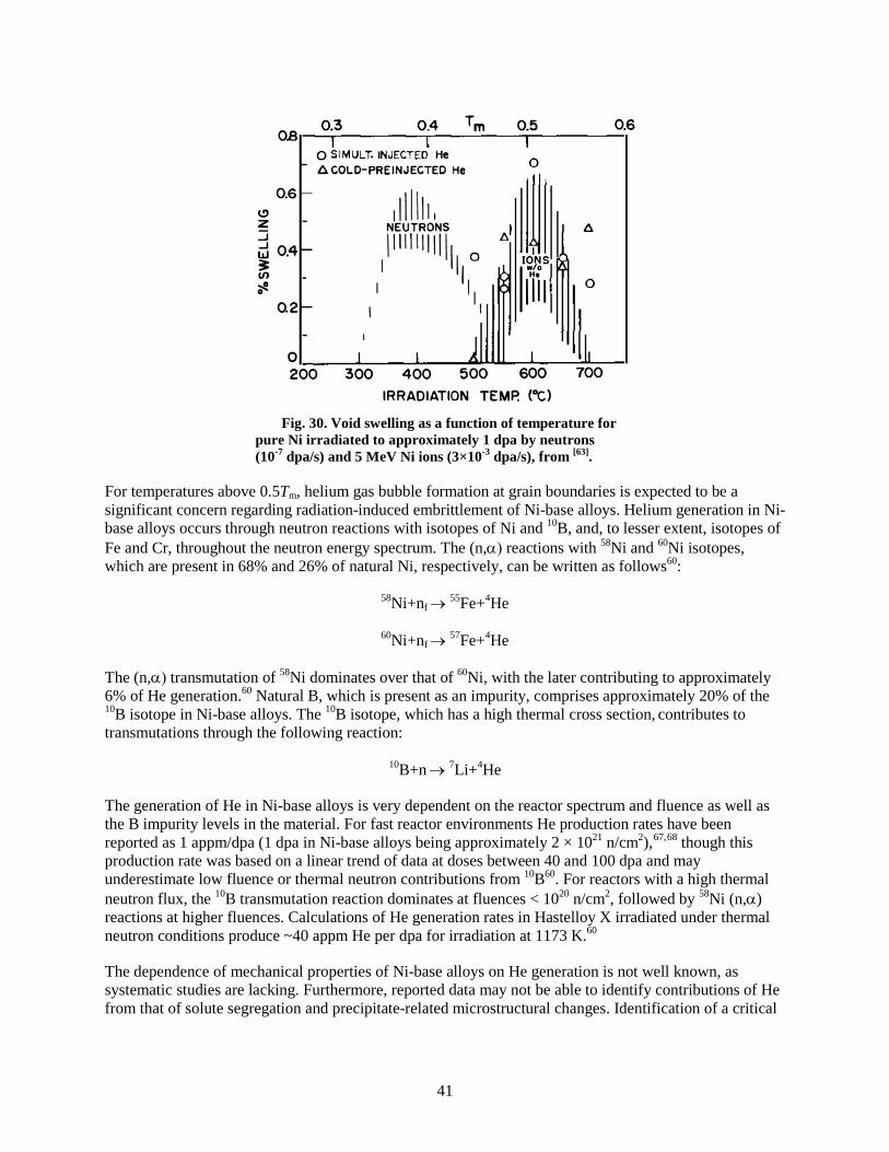
41
Fig. 30. Void swelling as a function of temperature for
pure Ni irradiated to approximately 1 dpa by neutrons (10-7 dpa/s) and 5 MeV Ni ions (3×10⁻³ dpa/s), from [63].
For temperatures above 0.5Tm, helium gas bubble formation at grain boundaries is expected to be a significant concern regarding radiation-induced embrittlement of Ni-base alloys. Helium generation in Ni-base alloys occurs through neutron reactions with isotopes of Ni and 10B, and, to lesser extent, isotopes of Fe and Cr, throughout the neutron energy spectrum. The (n,α) reactions with 58Ni and 60Ni isotopes, which are present in 68% and 26% of natural Ni, respectively, can be written as follows60:
58Ni+nf → 55Fe+4He
60Ni+nf → 57Fe+4He
The (n,α) transmutation of 58Ni dominates over that of 60Ni, with the later contributing to approximately 6% of He generation.60 Natural B, which is present as an impurity, comprises approximately 20% of the 10B isotope in Ni-base alloys. The 10B isotope, which has a high thermal cross section, contributes to transmutations through the following reaction:
10B+n → 7Li+4He
The generation of He in Ni-base alloys is very dependent on the reactor spectrum and fluence as well as the B impurity levels in the material. For fast reactor environments He production rates have been reported as 1 appm/dpa (1 dpa in Ni-base alloys being approximately 2 × 10²¹ n/cm2),67,68 though this production rate was based on a linear trend of data at doses between 40 and 100 dpa and may underestimate low fluence or thermal neutron contributions from 10B60. For reactors with a high thermal neutron flux, the 10B transmutation reaction dominates at fluences < 1020 n/cm2, followed by 58Ni (n,α) reactions at higher fluences. Calculations of He generation rates in Hastelloy X irradiated under thermal neutron conditions produce ~40 appm He per dpa for irradiation at 1173 K.60
The dependence of mechanical properties of Ni-base alloys on He generation is not well known, as systematic studies are lacking. Furthermore, reported data may not be able to identify contributions of He from that of solute segregation and precipitate-related microstructural changes. Identification of a critical

42
He level for a specific alloy therefore is not possible, with only scattered information available. Most irradiation data available are also limited to temperatures below 973 K.
For PE-16, irradiated in a mixed-spectrum test reactor, loss of ductility was measured following low dose exposures69,70 with ductility further being restricted at temperatures above 923 K or with increasing thermal fluence. For tests conducted on PE-16 implanted with Li and He,71 uniform elongation values fell to 1.5% in 10 appm Li plus 10 appm He-doped material tested at 923 K. A measured increase of 64 appm He in Hastelloy X following irradiation at 873 K to 3 × 10²¹ n/cm2, with a thermal-to-fast neutron ratio of 3 to 1, resulted in loss of ductility to 15% total elongation when tested at 873 K and to values near 2% when tensile-tested above the irradiation temperature.72
The suppression of the embrittlement effects of He can be achieved through two ways: (1) the reduction of the amount of B impurity in the alloy, which has shown to provide improvements in irradiated properties,73,74 and (2) the use of trapping through by ODS particles. As shown Fig. 29 (e), mechanical properties of MA-754 (Ni-20%Cr-1%Fe-0.05%C-0.3%Al-0.5%Ti-0.6%Y2O3) show superior mechanical properties at the operating temperature envisioned for the fission chamber. Unfortunately, little irradiation data exist on this alloy, but comparison to ferritic MA-957 can be made. Recent results obtained from microstructural analysis of MA-957 (Fe-20%Cr-4.5%Al-0.5%Ti-0.5%Y2O3) following neutron irradiation to 9 dpa at 773 K with ~380 appm He implanted uniformly to a depth of ~5 to 8 µm in transmission electron microscope (TEM) specimens, provide strong evidence that point defects and He atoms migrate to and are trapped by the Y2O3 nanoclusters.75 Similar work on MA-754 irradiated to 1.2 dpa at 773 K76 showed no cavity formation. Irradiation to 1.2 dpa slightly increased the average particle size with a decrease in particle density; however, these changes were statistically insignificant and show the stability of the microstructure. Very small mechanical property differences between the unirradiated and 1.2 dpa/773 K material are expected.
No clear data are available on Ni/UO2 or Ni/UN compatibility. The high activation of Ni in nuclear environments never made its use a desirable choice for fuel cladding. The thermodynamic free energy of formation for NiO, Cr2O3, and UO2
50 show that UO2 should be stable in contact with Ni/Ni-base alloys (Fig. 31).
Chemical compatibility studies of Ni-base alloys with FLiBe are highly dependent on the chemical composition of the alloy, impurity levels in the molten salt, and temperature. From experiments in the Molten Salt Reactor (MSR) program at ORNL from the 1950s to early 1970s, limitations to the use of Alloy 600 was found early on with respect to corrosion. Corrosion rates for Alloy 600 at 973 K and above were “excessive” for long-term use with fluoride systems.77 The two general mechanisms of corrosion, metal dissolution and oxidation of metals to ions,77,78 are found to occur. Due to the low solubility of metals in salt systems, metal dissolution is not a common form of attack. Molten salt corrosion is usually induced by reduction/oxidation (redox) reactions.
Table 3 contains a list of the standard free energies of formation of fluoride compounds at 800 and 1000 K. While LiF and BeF2 are more stable than fluorides of the alloys with nominal composition, corrosion of the alloys has been found to result from a several possible reactions that involve impurities in the salt, with the last being the strongest oxidant in the fuel salt system:
2HF+M = MF2+H2 (M=Ni, Cr, Fe)
XF2+Cr = CrF2+X (X=Ni, Fe)
2Cr+2UF4 = CrF2+2UF3

43
Fig. 31. Free energy of formation for various oxides, adapted from [50].
In the MSR program, alternative alloys were developed for operation in UF4 containing salts. While Ni with 1520% Mo showed good resistance to salt attack (see Table 3), it lacked sufficient mechanical strength and oxidation resistance. What was developed at ORNL was Hastelloy N, with composition within the range of 15-17%Mo, 6-8%Cr, 4-6%Fe, 0.04-0.08C. Hastelloy N suffers from two problems related to its use in MSRs, He embrittlement from (n,α) reactions, and grain boundary embrittlement of salt-exposed surfaces due to fission product (tellurium) segregation at grain boundaries.77 Modification of the alloy composition with Nb and Ti concentrations balanced at 2 wt % reduced grain boundary embrittlement issues.

44
Table 3. Table of standard free energies of formation of fluoride compounds at 800 and 1000 K, from [77]
Fluoride -∆Gf (800 K)
(kcal/gram-atom of F) -∆Gf (1000 K)
(kcal/gram-atom of F)
LiF 128.9 124.3
ThF4 111.4 107.9
PuF3 108.2 104.5
BeF2 107.8 104.4
UF3 104.3 100.9
UF4 99.3 95.9
TiF2 84.2 80.7
CrF2 79.8 76.6
NbF5 73.7 71.0
FeF2 71.0 67.9
MoF3 67.3 64.2
NiF2 63.7 60.1
Although a heavy emphasis was placed on corrosion properties of Hastelloy N during the MSR program, little FLiBe corrosion data are found on other alloys. The MA-754 and Haynes 230 alloys that show good to passing strength at 1073 K are rated as “very good” and “fair” in terms of fluoride salt corrosion resistance. However, the ratings come from the Next Generation Nuclear Plant (NGNP) program report.78 These arbitrary ratings were not backed by experimental data, and were more for comparison between different Ni-alloy grades. Unfortunately, additional reports make similar claims with references directed back to the same report from the NGNP program. Additional experimental data on MA-754 corrosion behavior in LiCl-Li2O at 923 K for up to 216 h was investigated.79 Uniform corrosion product was found to form up to 100 µm into material, below the 50 µm oxide layer, with the alloy showing better performance than Haynes 214.
Although the coolant salt system that will pass through the fission chamber will not encounter fuel contamination, the lessons learned from the Hastelloy N design are useful. However, the upper operating temperature for Hastelloy N is below 1073 K, making the alloy too weak for use in the current design. The reduced Cr is a benefit for the FLiBe corrosion resistance, but alloy strength suffers. Nitride formation is another concern with highly alloyed Ni-base alloys; nitride formation can create changes to the fission gas concentration inside the chamber. While resistance to nitridation is superior for MA-754 over alloys 617 and 600,80 it is not as immune as pure nickel. To counter the effects that alloy additions such as Cr, Fe, Ti, and Al may have on reacting with the set concentration of nitrogen gas in the fission chamber or reaction to the liquid metal coolant, a Ni outer coating over the Ni-alloy structural material may be an option.
Liquid fluoride salts will corrode oxide ceramics and will dissolve many common alloying elements (i.e., Al and Cr) from high-strength nickel-base alloys. Therefore, one common approach for protecting equipment in fluoride salt reactors is to surround them in a corrosion-resistant silicon carbide. However, as mentioned in Section 5.4.1, the sheath joint between SiC and the mineral-insulated (MI) -cable will be a significant challenge and a possible failure point for this design. Therefore, another approach to

45
protecting the fission chamber from both the high-pressure helium and fluoride salt environments is to select a high-strength high-nickel alloy (i.e., Alloy 800H, Inconel 617, or Haynes 230) as a structural shell and then to coat both the shell and the mineral-insulated (MI) cable with pure nickel, which would act as an environmental barrier coating to the fluoride salt. The shell and cable sheath would both be nickel-base alloys which would allow for straightforward welding between them. This weld would also be coated with pure nickel. The chamber and cable can be welded after the cable and chamber have been coated in nickel however; the coating may not survive the welding, so it would be preferable to coat both chamber and cable after they are welded. Also, interdiffusion between the substrate and the cladding may become a problem following long exposure times at 1073 K, and the coating would have to be a sufficient thickness so as not to expose the alloying metals to the fluoride salt solution.
A number of processes are available for cladding nickel on Ni-base alloys, but most suffer from an inability to easily coat large parts. In this case, the fission chamber will be welded to a ~10 meter long MI cable, which would make it a challenge for many processes. Electroplating is limited by the size of the electrolyte tank. Physical vapor deposition and sputtering both require a vacuum, which would be difficult to achieve with the large part being coated here. Similarly, CVD through the nickel carbonyl process would be difficult to achieve over the large part considered here.
Thermal spray, whereby the Ni cladding material is heated above its melting point and propelled by a stream of gas onto the substrate where it solidifies, is one approach that can be conducted on large parts at reasonable rates. The spraying equipment is portable, and spraying could be done at the installation site if necessary. For these reasons, thermal spraying the nickel cladding is the leading candidate for forming the environmental barrier coating.
The application of a Ni barrier coating on top of a Ni-alloy base metal will provide a means to prevent nitrogen reaction with the more reactive constituents of the alloy. Nitrogen absorption values for some select Ni and Fe base alloys are presented in Table 4.81 The nitridation resistance for the alloy is dependent on composition; increasing Cr, Fe, Mo, Al, and Ti increases susceptibility. While the alloy behavior in
Table 4 is for exposure in ammonia at 1253 K, it does provide a useful guide on nitride sensitivity.
Table 4. Nitridation resistance of select alloys in ammonia at 1253 K for 168 h, adapted from [81]
Alloy Nominal Composition* Nitrogen absorption
(mg/cm2)
214 Ni-16Cr-4.5Al-3Fe-0.5Mn-0.2Si-0.1Zr-0.05C 0.3
600 Ni-17Cr-10Fe-1Mn-0.5Cu-0.5Si-0.15C 0.9
X Ni-22Cr-18Fe-9Mo-1.5Co-0.6W-1Mn-1Si-0.1C 3.2
316 Fe-18Cr-14Ni-2Mn-3Mo-0.75Si-0.08C 6.0
304 Fe-20Cr-12Ni-2Mn-0.75Si-0.08C 7.3
446 Fe-30Cr-0.5Ni-1.5Mn-0.75Si-0.12C 12.9 * Maximum compositions of individual elements listed in weight percent.
Candidate metal coatings that show a resistance to nitrogen in addition to Ni include Pt, Ir , Rh, and Re. However, there are difficulties associated with these choices based on fabrication and for the case of Ir

46
and Rh a lack of sensitivity for the measured signal response required for the chamber.82 The lifetime of the coating can be estimated from the interdiffusion coefficients and the calculated diffusion distance, √(Dt), for exposure of 5 years as shown in Table 5. Very thick coatings on Ni-base alloys may be required. The effectiveness of a coating as a barrier to nitridation of the base metal alloy may only delay reactions, as the diffusivity of nitrogen through nickel is very high. However, reaction kinetics would dictate the ability of nitrogen to combine with Cr, for example, at the expense of Cr-carbides developed in the base metal.
Table 5. Diffusion data at 1200 K for possible coating/substrate combinations
Solute Solvent Diffusivity (m2/s) Diffusion distance in
5 years (µm) Reference
Pt* Pt 2.10 × 10⁻¹⁷ 58 83
W Ni 1.20 × 10⁻¹⁷ 43 83
Re Ni 8.00 × 10⁻¹⁸ 36 83
N Ni 5.85 × 10⁻¹² > 10 mm 81
*No data available for Pt in Ni, assumes data for self diffusion rates is similar.
5.1.4 Summary
Various metallic alloy candidate materials were investigated for the fission chamber application. No single alloy was found that has optimal properties required for strength and creep resistance at elevated temperatures or that is tolerant to radiation-induced damage, compatible with the nitrogen environment of the fission chamber, and resistant to LiF-BeF2 corrosion. The following summarizes the most promising metallic alloy candidates and highlights both their favorable and less-desirable properties. It also points out areas that may require further investigation to determine the feasibility of a particular alloy.
Stainless Steel:
MA-956 (Fe-20Cr-0.5Ti-4.5Al-0.05C-0.5Y2O3)
MA-957 (Fe-14Cr-1Ti-0.3Mo-0.25Y2O3)
• Excellent high-temperature strength retention.
• Microstructure tolerant to radiation-induced helium and defect generation.
• Nitride formation with fission chamber gas.
• Expected to have good compatibility with Li-containing coolants at temperatures ≤ 973 K. Determination of compatibility at higher temperatures requires further analysis.
• Commercial availability may be an issue.
Refractory Metal Alloys:
Nb-1Zr
• Suitable high-temperature strength and creep properties.

47
• Excellent liquid metal corrosion resistance.
• Known irradiation properties for conditions of fission chamber. Only refractory metal alloy that will not be sensitive to radiation embrittlement at 1073 K, so long as impurity concentrations are controlled.
• Poor compatibility with nitrogen in fission chamber gas, requiring the use of a Re coating.
• Good compatibility with UO2 expected. Typically used with a Re liner for UN fuels, but data are based on much higher use temperatures than is expected for fission chamber. Compatibility tests with UN at conditions expected of the chamber required.
Ni-base Alloys:
Alloy 214 (Ni-16Cr-4.5Al-3Fe-0.5Mn-0.2Si-0.1Zr-0.05C)
Alloy 230 (Ni-22Cr-14W-5Co-3Fe-2Mo-0.5Mn-0.3Al- 0.1C)
Hastelloy X (Ni-22Cr-18Fe-9Mo-1.5Co-0.6W-1Mn-1Si-0.1C)
MA-754 (Ni-20%Cr-1%Fe-0.05%C-0.3%Al-0.5%Ti-0.6%Y2O3)
• Age-hardened (precipitate-strengthened) grades not suitable for extended duration at 1073 K. Solution- and carbide-strengthened alloys more appropriate. ODS alloy MA754 also an excellent choice for elevated strength retention at high temperature.
• Compatibility with Li expected to be less desirable compared to Nb and stainless steel alloys. Favorable alloys for compatibility include those with lower Cr, Fe, Ti, and Al concentrations.
• Little irradiation data on non-age-hardenable alloy grades.
• He generation a concern at temperatures above 0.5Tm, leading to grain boundary embrittlement. ODS alloy less susceptible.
• Approximate 2 × 10²¹ n/cm2 dose (~ 1 dpa) irradiation dose not expected to generate significant He levels in Ni-base alloys. Control over boron levels needs to be maintained.
• Nitridation of Ni-base alloys can be significant, with grades containing less Cr, Fe, Si, and refractory metal additions preferred.
• Ni-ODS based on pure Ni or a Hastelloy N composition is possible but requires experimental assessment of irradiation, high-temperature strength, and corrosion properties.
5.2 JOINING
Although the final selection of insulator and chamber materials has not been finalized, the list of candidate materials has been generally reduced to aluminum oxide and silicon carbide ceramics, commercially pure nickel, nickel alloys, cermets and Kovar® (Ni-29, Co-17, C- <0.01, Si-0.2, Mn-0.3, Fe- ~53.5), or other low expansion alloys. The possible joining processes to join of the materials, depending on the final material selections and design, are:

48
• Metal to metal: brazing/welding
• Cermet to metal: brazing
• Metal to ceramic: brazing/diffusion bonding/reaction bonding
• Ceramic to ceramic: brazing/diffusion bonding/reaction bonding/glass-ceramics joining/transient eutectic-phase joining
A fitness for service approach must be used to determine the joining method and filler metals employed for a material combination. Some of the factors that must be considered are:
• Required strength or ductility at temperature • Material stability with time at temperature • Temperature cycling • Compatibility with internal environment • Compatibility with external environment • Irradiation effects • Assembly process
Nickel, nickel alloys and Kovar® are readily welded by most fusion-welding processes to produce joints with properties similar to the base metals. In the fission chamber, the components to be joined are generally small and thin. Electron beam and laser beam are the recommended welding processes due to the low heat input of the processes, which will prevent possible remelting of nearby braze joints. These welding processes are also applicable to the welding of plasma spray coatings and the connection of the cable leads to the fission chamber electrode connections.
Other welding processes that may be used in the fabrication of the fission chamber are resistance spot welding, ultrasonic welding, and diffusion welding. Resistance spot welding and ultrasonic welding are applicable to closing of the gas fill tube after filling the chamber with the appropriate gas mixture. Either brazing or diffusion bonding may bond silicon carbide to itself. Depending on the need to bond silicon carbide to itself and the assembly point where this connection is required, silicon carbide may be metalized with a suitable alloy such as nickel or titanium or a thin foil of these materials may be placed between the components and diffusion bonded with the application of pressure and heat to produce a hermetic seal.
Brazing will be required for attachment of the electrodes to the electrical feed-throughs penetrating the insulator; joining of metal components where welding is not applicable, accessible, or desired; hermetic seals of ceramic components; and joints between metals and nonmetals. Depending on the application and point of assembly operations, an active brazing alloy (ABA) or vacuum-grade (VG) brazing filler metals will be used. The brazing alloys likely to be useful for assembly of the fission chamber are generally limited to select gold, nickel, or copper alloys to limit interaction and absorption of nitrogen and the levels of low-melting-point or high-vapor-pressure constituents. An additional limitation on the brazing alloys is limiting the boron content that will be a source of helium embrittlment during service. A failure mechanism seen in failed fission chambers has been the deposition of metal vapors onto electrical insulators, resulting in electrical shorts between electrodes. Use of VG brazing alloys limits the level of high-vapor-pressure elements within the alloy. The use of VG filler metals will minimize the vaporization and transport of high-vapor-pressure elements to these and other surfaces within the fission chamber during high-temperature operation.

49
The brazing of oxide- and carbide-based structural ceramics is difficult with conventional brazing techniques due to their chemical stability, which leads to poor wetting by liquid metals. To overcome this obstacle, two methods should be considered. The most common method of joining aluminum oxide ceramics is by metalizing the areas to be joined prior to brazing to improve wetting by the liquid brazing alloy. This process is commonly known as the moly-manganese or sintered-metal-powder process, and uses a combination of molybdenum and manganese oxides and metals that are high-fired to produce a metallic glass on the structural ceramic. The final preparation of the surfaces for brazing includes either nickel plating or hydrogen sintering of nickel oxide.
An alternative to the moly-manganese technique is direct ABA brazing of a ceramic to itself or to nickel alloys. ABAs permit direct, one-step brazing by incorporating an active metal (generally small amounts of titanium, zirconium, or vanadium) into the brazing alloy to react with the ceramic surface during brazing to allow wetting by the liquid braze alloy. A brazing study is currently under way to evaluate ABA brazing of silicon carbide to nickel alloys. The initial testing being performed will evaluate brazing of an alpha silicon carbide to austenitic stainless steel using both a copper- and gold-based ABA brazing materials. The selection of base materials for assembly is based on representative thermal expansion coefficients and on the availability of the materials. Test coupons will be initially evaluated on braze material flow and helium leak rates. Additional testing is planned to perform temperature cycling to the operating temperature and to determine braze strength.
5.3 MATERIALS FOR CONNECTORS AND LEADS
Many of the same materials issues associated with the chamber materials apply to the lead materials. It is expected that the same materials will be used for leads and internal wiring as will be used for the chamber electrodes, with the exception that cermets are likely feed-through materials. One additional consideration for the lead materials is that small-diameter wires can become embrittled due to grain growth at lower temperatures than is the case for thicker sections. However, the metals under consideration for chamber materials would be suitable for lead wires. If other materials are identified for use as small-diameter wires, the grain growth behavior would need to be examined.
5.4 CARBON/CARBIDE CERAMICS
Carbon and carbide structures were considered in previous work82 for a high-temperature fission chamber. We added considerations of carbide ceramic structures in the present work. These materials offer the advantages of weight reduction (~2.5 g/cm3 as opposed to nickel/iron-based metals with densities in excess of 7 g/cm3), maintenance of strength at high temperatures, insensitivity to thermal neutrons, and mostly good compatibility with fill gases. The major issues associated with these materials are related to joining (they often resist wetting by brazing metals) and the possibility of forming cyanogen when heated and in contact with the gaseous nitrogen in the fill gas.
Several criteria were considered in Ref. 82 in selecting the materials for fabrication of component parts for a high-temperature fission chamber:
• thermal properties (melting point, thermal stability, low vapor pressure);
• chemical properties (inertness with respect to nitrogen at high temperature);
• mechanical properties (low coefficient of thermal expansion, mechanical strength, high resistance to vibrations, high fracture toughness, elastic properties);
• electrical conductivity (such that it can be used as an electrode);
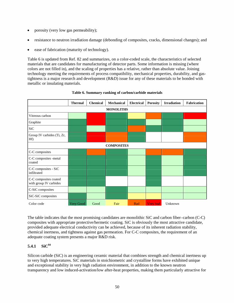
50
• porosity (very low gas permeability);
• resistance to neutron irradiation damage (debonding of composites, cracks, dimensional changes); and
• ease of fabrication (maturity of technology).
Table 6 is updated from Ref. 82 and summarizes, on a color-coded scale, the characteristics of selected materials that are candidates for manufacturing of detector parts. Some information is missing (where colors are not filled in), and the scaling of properties has a relative, rather than absolute value. Joining technology meeting the requirements of process compatibility, mechanical properties, durability, and gas-tightness is a major research and development (R&D) issue for any of these materials to be bonded with metallic or insulating materials.
Table 6. Summary ranking of carbon/carbide materials
Thermal Chemical Mechanical Electrical Porosity Irradiation Fabrication
MONOLITHS
Vitreous carbon
Graphite
SiC
Group IV carbides (Ti, Zr, Hf)
COMPOSITES
C-C composites
C-C composites -metal coated
C-C composites - SiC infiltrated
C-C composites coated with group IV carbides
C-SiC composites
SiC-SiC composites
Color code Very Good Good Fair Bad Very bad Unknown
The table indicates that the most promising candidates are monolithic SiC and carbon fiber–carbon (C-C) composites with appropriate protective/hermetic coating. SiC is obviously the most attractive candidate, provided adequate electrical conductivity can be achieved, because of its inherent radiation stability, chemical inertness, and tightness against gas permeation. For C-C composites, the requirement of an adequate coating system presents a major R&D risk.
5.4.1 SiC84
Silicon carbide (SiC) is an engineering ceramic material that combines strength and chemical inertness up to very high temperatures. SiC materials in stoichiometric and crystalline forms have exhibited unique and exceptional stability in very high radiation environment, in addition to the known neutron transparency and low induced-activation/low after-heat properties, making them particularly attractive for

51
use in harsh radiation environments.85,86 High-purity, fully crystallized SiC are commercially produced either by CVD or by pressure-assisted sintering. The maximum use temperature approaches 2000 °C, well above the operating temperature of the proposed fission chamber. The typical flexural strength of CVD SiC is ~400 MPa at room temperature. That strength is retained to above 1800°C, with detectable creep deformation starting at 1400°C to 1500°C. With a typical fracture toughness of ~3.5 MPa-m1/2, SiC in monolithic form is not suitable for applications that require high impact resistance. The coefficient of thermal expansion from room temperature to 800°C is ~4 × 10⁻⁶/K, which is smaller than most other ceramics and metals (with the exception of tungsten and molybdenum). Perhaps most importantly, SiC is claimed to be impervious to the infiltration of gas, which makes it attractive for use as the outer body of the fission chamber. As mentioned previously, joining of SiC to itself and to metals (the sheath of an MI cable), requires investigation. The comprehensive baseline properties of high-purity CVD SiC in as-deposited and neutron-irradiated conditions are summarized in Ref. 85.
Ceramic SiC is unlikely to be affected by FLiBe,87 although more detailed study is needed to fully address the chemical compatibility of SiC in the FLiBe flow in the presence of metallic components and temperature distributions. However, because of the anticipated chemical compatibility with molten salt, SiC is attractive as an outer environmental barrier for the chamber because it would not require protection from molten salt coolant. However, the brazes that are contemplated for SiC are attacked by FLiBe and so a pure nickel coating, nominally facilitated by the molybdenum-manganese process remains likely.
The effect of radiation on SiC has been investigated.88 At the specified fluence level (1020 n/cm2 for 1 MeV equivalent), radiation damage should not be a problem.89
Some grades of SiC have free carbon.90 In a nitrogen-containing atmosphere, it is likely that these grades will form cyanogen and will require a metal coating.
The main issue for high-purity SiC for the fission chamber application is its limited electrical conductivity. Beta-phase SiC, which is the polytype that constitutes CVD SiC, is inherently a wide band-gap semiconductor. The wide gap of ~2.4 eV makes beta-phase SiC of ideally high purity an insulating material at room temperature. Although the electrical conductivity increases with increasing temperature, that will not qualify pure SiC as a conductor. Commercial SiC, even if claimed as high purity, typically contains very small amount of N, B, or Al, any of which makes it an impurity semiconductor. N is most commonly introduced to CVD process to make SiC conductive. For example, Dow Chemical sells CVD SiC in both standard and high-resistivity grades with the room-temperature electrical conductivity of ~1000 S/m and ~0.02 S/m, respectively. Temperature dependence of electrical resistivity is determined by the band gap of the impurity, specifically N for the standard grade and other impurities for the high-resistivity grade. Fig. 32 shows the temperature-dependent electrical resistivity of the Dow Chemical CVD SiC.91

52
Fig. 32. Temperature dependence of electrical resistivity for
commercial CVD SiC.
Under neutron irradiation that imposes atomic displacement, electrical properties of impurity semiconductors change drastically. This is because all of the specie, density, and mobility of the responsible carriers change upon irradiation. A very small neutron dose may drastically modify the electrical properties of these materials. For the case of SiC as an impurity semiconductor, radiation-produced defects replace the impurities as the electron-trapping centers at the early irradiation. An example of electrical conductivity measured for Dow Chemical CVD SiC is presented in Fig. 33.92 Based on the data, electrical conductivity of CVD SiC after neutron irradiation at 800°C likely falls in a range 100 to 1000 S/m.

53
Fig. 33. Electrical conductivity of commercial high purity
CVD SiC after neutron irradiation at elevated temperatures.
Further increasing the electrical conductivity of SiC is most certainly realized by embedding or coating a conducting medium on the surface or inside the SiC wall by various ways. The promising options include the incorporation of pyrocarbon (PyC) interlayer inside the CVD SiC wall. The CVD SiC tube will likely be fabricated by depositing SiC onto a graphite mandrel. Therefore, thin layers of PyC may be easily embedded by interrupting the CVD process for SiC and switching the reactant gas to any carbon precursor for a short period of time. Producing alternating layers of PyC and CVD SiC is routinely performed in the commercial process of SiC-matrix composite fabrication. Alternatively, carbon fibers may be incorporated in the inner portion of the SiC body to enable adequate electrical conduction along the desired direction. Chemical-vapor infiltration to produce a composite of an SiC matrix on a carbon fiber composite substrate is an established industrial material technology. The selection of the appropriate conductive medium and the method of incorporation will vary depending on the requirement of conductivity.
5.4.2 Thermodynamic Stability of Carbon in Nitrogen at High Temperatures
We repeat here the analysis of cyanogen equilibrium found in Ref. 82 because we are considering the use of a carbon getter, and it is important to understand the necessity to control exposed reactive carbon. At elevated temperatures, a direct reaction between carbon and nitrogen occurs, and it is necessary to consider the effects on both the fill gas and the carbon/carbide structure. The direct reaction between carbon and nitrogen gas at elevated temperatures leads to formation of cyanogen gas:
2 2 22C + N C N↔ (19)
The reaction is endothermal, and is favored by an increase of temperature. The enthalpy and entropy of formation in cyanogens in gas phase from elements are respectively ∆fH0
gas = 306.7 kJ/mol and ∆fS0gas =
241.6 J/mol-K.93 The equilibrium constant for cyanogen formation can be written as
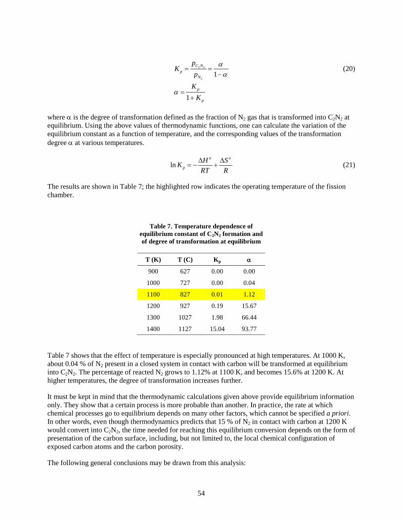
54
2 2
21
1
C Np
N
p
p
pK
p
KK
αα
α
= =−
=+
(20)
where α is the degree of transformation defined as the fraction of N2 gas that is transformed into C2N2 at equilibrium. Using the above values of thermodynamic functions, one can calculate the variation of the equilibrium constant as a function of temperature, and the corresponding values of the transformation degree α at various temperatures.
lno o
pH SK
RT R∆ ∆
= − + (21)
The results are shown in Table 7; the highlighted row indicates the operating temperature of the fission chamber.
Table 7. Temperature dependence of equilibrium constant of C2N2 formation and of degree of transformation at equilibrium
T (K) T (C) Kp α
900 627 0.00 0.00
1000 727 0.00 0.04
1100 827 0.01 1.12
1200 927 0.19 15.67
1300 1027 1.98 66.44
1400 1127 15.04 93.77
Table 7 shows that the effect of temperature is especially pronounced at high temperatures. At 1000 K, about 0.04 % of N2 present in a closed system in contact with carbon will be transformed at equilibrium into C2N2. The percentage of reacted N2 grows to 1.12% at 1100 K, and becomes 15.6% at 1200 K. At higher temperatures, the degree of transformation increases further.
It must be kept in mind that the thermodynamic calculations given above provide equilibrium information only. They show that a certain process is more probable than another. In practice, the rate at which chemical processes go to equilibrium depends on many other factors, which cannot be specified a priori. In other words, even though thermodynamics predicts that 15 % of N2 in contact with carbon at 1200 K would convert into C2N2, the time needed for reaching this equilibrium conversion depends on the form of presentation of the carbon surface, including, but not limited to, the local chemical configuration of exposed carbon atoms and the carbon porosity.
The following general conclusions may be drawn from this analysis:

55
1. At the working temperature of the chamber (1073 K), the direct reaction of carbon and nitrogen to form cyanogen is thermodynamically favorable. Assuming that the initial gas composition is 10 % N2 in Ar, at chemical equilibrium at 1073 K the gas composition would be 9.89 % N2, 0.11 % C2N2, 90 % Ar. One cannot specify the rate at which this composition would be achieved or the rate of corrosion of exposed carbon-containing components.
2. The effect of cyanogen formation on carbon corrosion may or may not be minimal. A cylinder 5 cm in diameter and 30 cm long (0.588 liter), filled with gas at 1 bar at 1073 K, contains 0.0066 moles of gas. Assuming an initial composition of 10% N2, there are 0.00066 moles N2 available in initial conditions. At equilibrium at 1073 K, 1.12% of this amount, or 7.38 × 10⁻⁶ moles of N2, would be converted to C2N2, which would corrode twice as many moles of carbon, 1.48 × 10⁻⁵ moles of carbon or 0.177 mg of carbon. Considering that the chamber would contain approximately 700 g of carbon/carbide, there is no reason to believe that carbon coming out of the cyanogen will directly replace carbon being scavenged by the nitrogen, although the carbon lost to cyanogen is negligible and at any given time only small amounts of carbon scavenged from the chamber components are in the fill gas. Consequently, it is not obvious that over a sufficiently long time, exposed carbon would not be transported around the chamber to be deposited on all surfaces.
3. While the presence of cyanogen in the fill gas will probably not alter the detection characteristics significantly (the mass of cyanogen would be only 2% of the mass of N2), radiolysis of the gas will undoubtedly cause an equilibrium amount of carbon dust to condense on all surfaces. Such dust on the electrodes will not be significant, but sufficient deposition to provide/produce a conducting path across insulators, or to cause an arc to strike between the electrodes, would disable the chamber. Consequently, it will be necessary to test carbon/carbide structural materials by baking samples at 1073 K in nitrogen, measuring weight gain or loss and cyanogen production, and examining the samples for carbon deposition.
5.5 INSULATORS
The fission chamber requires insulating end caps in order to hold in place and electrically isolate inner and outer high-voltage cylinders from a middle ground cylinder. This insulator must:
• function at 1073 K and survive a thermal neutron flux of 1013 n/cm2/s for 2 years;
• provide electrical feed-throughs to transmit the signal through the insulator to the outside of the chamber;
• contain a port or nipple used to insert the fill gas into the chamber, which will then be hermetically sealed;
• not react with the Ar/N2 chamber fill gas;
• be impermeable to the fill and external gases;
• be thermomechanically compatible with the metal cylinders.
An alternative to putting a filling/evacuation port through the insulator is to assemble the chamber in an atmosphere of the fill gas after baking out all the components. However, this has other possible problems, such as interactions between the fill gas, braze constituents, and chamber components at brazing temperatures that will exceed 1073K.

56
In addition, an insulator shell will encase the entire fission chamber in order to prevent the fill gas from interacting with the outer shell (either nickel/nickel alloy or silicon carbide) and the MI cable and to maintain the mechanical integrity of the chamber.
Judging from previous experience with fission chambers, the source of failure is likely to be the insulator-to-conductor seal at the hot-end seal, which must retain hermeticity over the mission lifetime. Therefore, design of the insulator has taken a twofold path: first, selection of a bulk insulating material and, second, designing a suitable brazing system for connection of the insulator to the metal.
5.5.1 Bulk Insulator
The insulator will be used to provide electrical separation between the electrodes. Given the required operating temperature of 1073 K at a neutron fluence of 1021 n/cm2 over a minimum of 2 years, there are a number of potential candidate materials including Al2O3 (polycrystalline and single crystal sapphire), spinel (MgAl2O4), and MgO. In addition to alumina and MgO, Ref. 82 considered BeO and SiO2 and concluded that sapphire was the best choice, with polycrystalline alumina running a close second. All of these have suitably high resistivity with low-to-zero radiation-induced electrical degradation , and this was the factor deciding in favor of sapphire. Although there is extensive literature demonstrating its electrical stability94 under the current design conditions, poly-Al2O3’s lower resistivity as compared to single crystal sapphire’s and sapphire’s minimal number of reactive defect sites argued in favor of this material. However, high resistivity can be a detriment because of the tendency to build up charge and facilitate an electrostatic discharge that damages the chamber. Polycrystalline Al2O3’s resistivity at 1273 K is naturally one to three orders of magnitude smaller than that of sapphire, making it quite competitive with single crystal sapphire.
Joining poly-Al2O3 to metals is well understood and widely used throughout the electronics industry. This is important because the poly-Al2O3 may serve an additional function in the fission chamber: it may serve as a substrate onto which are deposited the metal electrodes. In consideration of this function, we note that Al2O3 has a coefficient of thermal expansion (CTE) closely matching that of platinum, but the CTE of nickel alloy is a factor of two larger. If a Ni base alloy is used as the metal, then the CTE mismatch with the alumina will become an issue since the CTE of Ni is ~15 × 10-6 strain/ºC. In this case, a strain-relieving Pt ring may be needed around the sapphire feed-through to prevent stress generation at the joint. The Pt/Ni weld joint is expected to be sufficiently ductile to withstand the strain generated during heat-up.
5.5.2 Insulator-to-Metal Seal
Grooves will be machined or cast in the alumina end caps in order to hold the metal cylinders so as to preserve the spacing between them. The fill gas needs to flow between the cylinders, so there is no need to create a hermetic seal at the metal/insulator connection. Moreover, the metal cylinders will not be bearing any load (other than their own weight), so the metal/insulator connection need not be mechanically strong. The main requirement is to transmit the current from the cylinders to the electrical feed-throughs. In order to do this, the grooves in the alumina end cap will be coated with nickel to maximize the electrical contact between the cylinders and the electrical feed-through, which will be a Kovar pin protruding out of the metal groove. By coating the entire groove with Ni rather than attaching to the cylinders at one point with a Ni wire, a previously observed failure mode (the breaking of the wire due to the rotation of the metal cylinders) is eliminated.
Electrical contact between the cylinder and the Ni-coated groove will be maintained by tapering the groove and wedging the metal cylinder into place during construction. Since the entire groove will be coated, there will be multiple points of electrical contact at all times. Conversely, the metal cylinders may also be brazed into the Ni-coated grooves, thereby increasing the mechanical integrity of the joint.
57
5.5.3 Electrical Feed-Throughs
Alumina-to-Kovar or copper seals are ubiquitous in the electronics industry and employ the well-known “moly-manganese” (Mo-Mn) process, whereby a paint containing powders of molybdenum and manganese (or their oxides) is applied to the Al2O3 and fired in H2 so that the manganese is present as MnO and the molybdenum as a metal.95 The MnO forms a glassy phase at the interface with the alumina grain boundary phase. This glassy phase forms a composite with the Mo at the interface, forming a strong chemical bond. This Mo-Mn layer then provides wettability for other alloys (such as Ni) to be deposited on the surface of the insulator.
The feed-throughs will be made in the alumina end cap by drilling or casting holes into the ceramic that line up with the three grooves that the cylinders fit in. There will be one hole for each groove. The surface of the hole will then be prepared using the Mo-Mn process and then a Kovar pin will be brazed in the hole. Kovar is a nickel-cobalt ferrous alloy that has a coefficient of thermal expansion close to that of alumina and is extensively used in the electronics industry for metal-alumina seals. The resulting feed-through will hermitically seal the chamber interior from the exterior and the MI cable and will have a large cross section, ensuring good electrical conduction through the end cap.
5.5.4 Nipple for Fill Gas Insertion
The gas will need to fill the chamber (sufficient to reach a pressure of 1 atm at1073 K), and then the nipple will be permanently sealed. Similar to the feed-throughs, a Kovar nipple or tube will be brazed into the distal end of the chamber. Following filling with the noble gas-N2 mixture, the nipple will be crimped shut. One concern is that Kovar may not be ductile enough to be crimped, in which case, a Kovar plug could be welded onto the nipple.
5.5.5 Chemical and Mechanical Stability
Under the operating conditions, alumina will not react with N2. Alumina may be permeable to high-pressure He at 1073 K.96 Therefore, it will be important to use the outer shell to shield the alumina from the He coolant gas. However, the Ar-N2 fill gas (at atmospheric pressure) is not expected to diffuse out of the alumina chamber.
The coefficient of thermal expansion of alumina is ~8 ppm/ºC which is approximately half that of most nickel alloys. As explained previously, the current design requires brazing only at the end of the cylinder at which the electrical contacts are located. The lack of a chemical bond at the distal end allows the cylinders to “breathe” as the temperature changes, thereby eliminating the thermomechanical mismatch stress between the cylinders and the outer alumina shell. The fracture strength of alumina will range from 300 to 500 MPa at room temperature and will not decline significantly up to 1073 K. Since the alumina shell will not see the high-pressure He coolant gas, the alumina shell will not fracture under these conditions.
5.5.6 Alumina to Alumina Joint
The two alumina end caps will need to be hermetically joined to the alumina cylinder that will encase the fill gas and conductors and prevent the gas from reaching the outer protective shell (either Inconel or SiC). This will be accomplished by using the metalizing/braze system, similar to the method proposed for sealing the conductive feed-throughs. However, there will be direct electrical connection from the inner diameter to the outer diameter of the vessel via the metalizing joint, so care will have to be taken to ensure that a connection is not made between this joint and the outer conducting cylinder.

58
5.5.7 Alternative Design: Alumina Substrates for the Conducting Cylinders
An alternative approach to the conducting cylinders is to use alumina cylinders coated with a few microns of nickel. The alumina surface would be prepared using the moly-manganese process described above and then coated with nickel. This design would ensure the mechanical integrity of the cylinders and their spacing while not impacting the electrical signal. This scheme has the advantage of reducing the amount of nickel in the system and increasing neutron sensitivity.
5.6 NEUTRON TRANSPORT
A number of factors play into the sensitivity of a fission chamber. The materials of construction, the thickness and composition of the neutron reactive layers (NRLs), as well as the size, geometry and number of NRLs all contribute to the sensitivity of the instrument. Previous work82 indicated that the general design concept of utilizing multiple concentric cylinders was feasible and capable of achieving the goals of this work. Initial estimates indicated that three concentric cylinders would be necessary to create two annular detection chambers to achieve the desired sensitivity. A more in-depth analysis and exploration of the design were then performed to identify optimal parameters and material compositions.
The sensitivity of a fission chamber is a combination of two factors: (1) the probability that a neutron entering the detector causes a fission event to occur in one of the NRLs and (2) the probability that a fission product from a fission event is ejected into a gas chamber with sufficient energy to be registered as a count. The first will hereafter be referred to as the “fission production efficiency” (FPE) while the second will be referred to as the “probability of detection” (PD). FPE is expressed in units of fission events per second per neutron per square centimeter per second or fps/nv. PD is expressed as counts per fission or equivalently cps/fps. Sensitivity is then simply the product
PDFPES ⋅= (22)
which is in units of cps/nv.
The relationship that PD and FPE have with the various parameters of design were independently computed. The resulting relationships were then propagated using Eq. (22), and the parameters yielding the optimal sensitivity were identified. The methods of calculating FPE and PD are discussed in the following sections.
5.6.1 Probability of Detection
Conversion detectors, a category of radiation detectors encompassing fission chambers, require that one or more reaction products born in a conversion region reach the sensitive region of the detector after a reaction so that sufficient energy can be deposited for a count to register. In a fission chamber, the conversion region is typically a thin film composed of a material containing a fissionable isotope, such as 235U. The sensitive region of a fission chamber is simply a gas across which a bias has been applied so that, when a charged particle passes through it depositing energy via ionization of the gas, electrons and ions are drifted apart to their respective electrodes, inducing a pulse of current in an external measurement circuit.
In a fission chamber, the heavy and light fission fragments (FFs) resulting from a fission event in the conversion layer are ejected isotropically but always in opposite directions from one another to first order. As fission fragments (FFs) travel through the conversion layer, they lose energy, primarily through Coulomb interactions. Depending upon trajectory and the geometry of the conversion layer, either one or possibly even both FFs may enter the sensitive region of the detector. If at least one FF enters the

59
sensitive gas region and deposits sufficient energy, a current pulse will be measured and the fission event will be detected. Unfortunately, not all fission events result in an FF depositing sufficient energy in the gas region.
The probability that an FF will reach the surface of a thin film is strongly dependent upon how deep into the film the event occurred and the effective range of the FF. FFs of a given size and energy have a well-known range (distance that they travel before stopping) that can be estimated using the TRIM code.97 However, the “effective” range is a distance somewhat smaller than the total range. The effective range is the distance an FF travels until it has less than the minimum measureable amount of energy. The minimum measureable amount of energy depends on electronic noise and other factors but can range from a few hundred thousand electron volts to tens of millions of electron volts. Being conservative, it was estimated that the instrument being designed would require at least 30 MeV of energy for worst-case and 10 MeV for best-case scenarios; the effective ranges of the FFs were computed for 10, 15, 20 and 30 MeV.
Fission events produce many of products, typically including a heavy and a light fragment. The mass distribution of fission products for 235U fission induced by thermal neutrons is shown in Fig. 34. Only one pair of representative fission fragments was utilized for the probability of detection investigation: a 96 MeV 100Zr light fragment and a 72 MeV 134Te heavy fragment.
lists the effective ranges of these FFs for various minimum measureable energy values in two candidate NRL materials, U2N3 and U3O8.
Fig. 34. Mass distribution of fission products for 235U.

60
Table 8. Effective ranges of representative fission products
Minimum energy (MeV)
Effective range (µm)
U2N3 U3O8
96 MeV 100Zr 72 MeV 134Te 96 MeV 100Zr 72 MeV 134Te
0 8.58 6.83 10.28 8.14
10 6.38 4.91 7.64 5.81
15 5.71 4.18 6.86 4.96
20 5.17 3.60 6.24 4.29
30 4.27 2.69 5.17 3.22
The computation of PD involved two candidate NRL materials, U2N3 and U3O8, as well as the thickness of the NRL layer. Using a Monte Carlo technique in which fission events were uniformly generated throughout the depth of an NRL layer and FFs were ejected isotropically, the probability that the path length of one of the ejected FFs to the surface of the sensitive region was less than its respective effective range was scored. Fig. 35 and Fig. 36 plot the results of the computation.
Fig. 35. Probability of detection for U2N3 NRLs at various minimum measureable
energy settings.
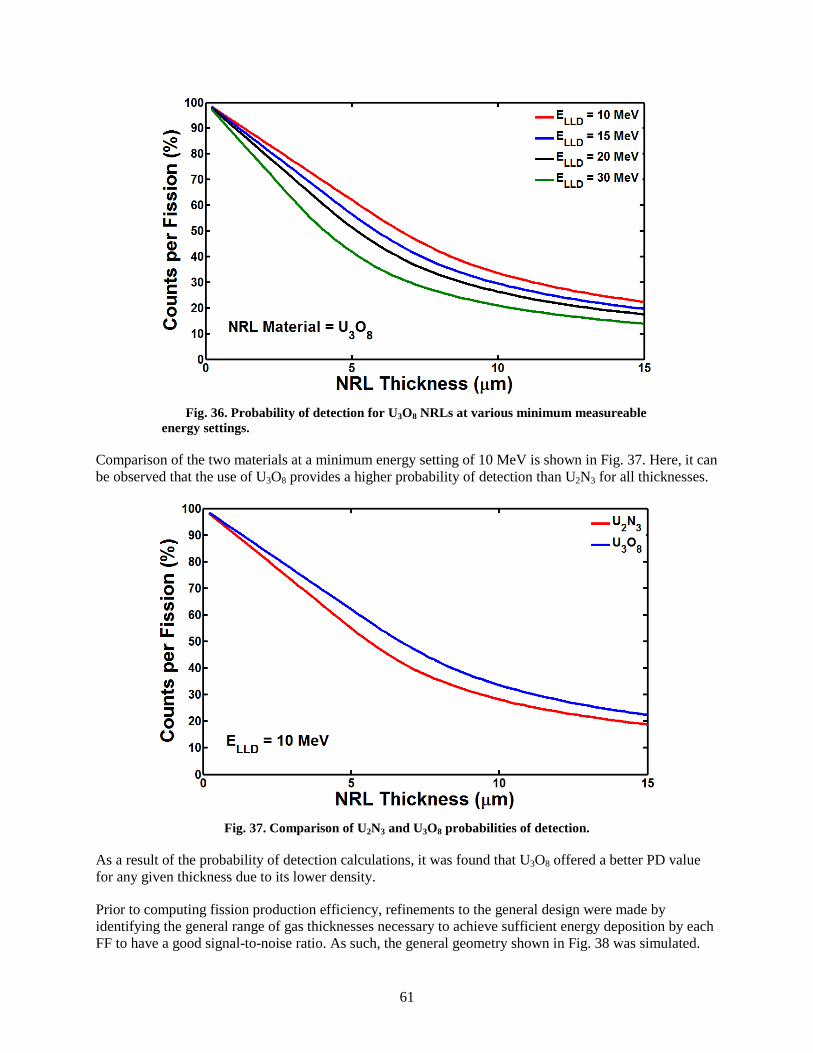
61
Fig. 36. Probability of detection for U3O8 NRLs at various minimum measureable
energy settings.
Comparison of the two materials at a minimum energy setting of 10 MeV is shown in Fig. 37. Here, it can be observed that the use of U3O8 provides a higher probability of detection than U2N3 for all thicknesses.
Fig. 37. Comparison of U2N3 and U3O8 probabilities of detection.
As a result of the probability of detection calculations, it was found that U3O8 offered a better PD value for any given thickness due to its lower density.
Prior to computing fission production efficiency, refinements to the general design were made by identifying the general range of gas thicknesses necessary to achieve sufficient energy deposition by each FF to have a good signal-to-noise ratio. As such, the general geometry shown in Fig. 38 was simulated.
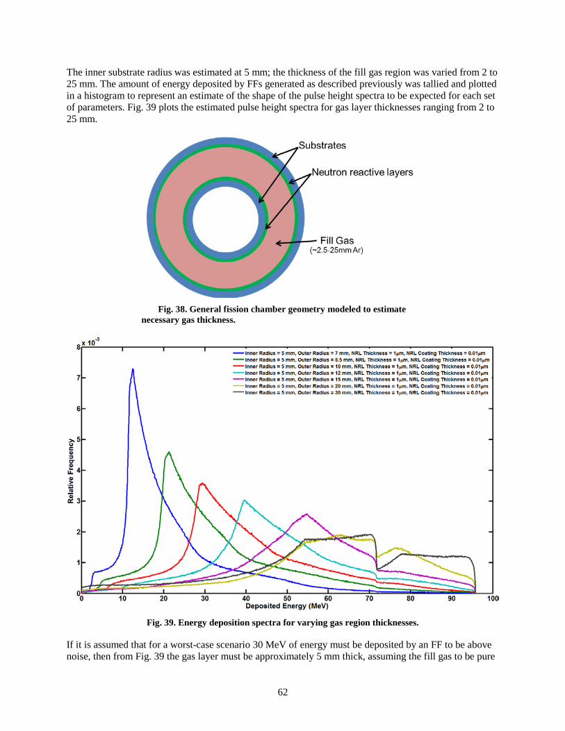
62
The inner substrate radius was estimated at 5 mm; the thickness of the fill gas region was varied from 2 to 25 mm. The amount of energy deposited by FFs generated as described previously was tallied and plotted in a histogram to represent an estimate of the shape of the pulse height spectra to be expected for each set of parameters. Fig. 39 plots the estimated pulse height spectra for gas layer thicknesses ranging from 2 to 25 mm.
Fig. 38. General fission chamber geometry modeled to estimate
necessary gas thickness.
Fig. 39. Energy deposition spectra for varying gas region thicknesses.
If it is assumed that for a worst-case scenario 30 MeV of energy must be deposited by an FF to be above noise, then from Fig. 39 the gas layer must be approximately 5 mm thick, assuming the fill gas to be pure
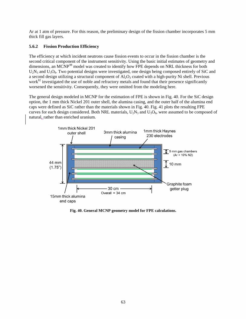
63
Ar at 1 atm of pressure. For this reason, the preliminary design of the fission chamber incorporates 5 mm thick fill gas layers.
5.6.2 Fission Production Efficiency
The efficiency at which incident neutrons cause fission events to occur in the fission chamber is the second critical component of the instrument sensitivity. Using the basic initial estimates of geometry and dimensions, an MCNP98 model was created to identify how FPE depends on NRL thickness for both U2N3 and U3O8. Two potential designs were investigated, one design being composed entirely of SiC and a second design utilizing a structural component of Al2O3 coated with a high-purity Ni shell. Previous work82 investigated the use of noble and refractory metals and found that their presence significantly worsened the sensitivity. Consequently, they were omitted from the modeling here.
The general design modeled in MCNP for the estimation of FPE is shown in Fig. 40. For the SiC design option, the 1 mm thick Nickel 201 outer shell, the alumina casing, and the outer half of the alumina end caps were defined as SiC rather than the materials shown in Fig. 40. Fig. 41 plots the resulting FPE curves for each design considered. Both NRL materials, U2N3 and U3O8, were assumed to be composed of natural, rather than enriched uranium.
Fig. 40. General MCNP geometry model for FPE calculations.

64
Fig. 41. FPE of four fission chamber designs as a function of thickness
of NRLs.
As can be concluded from Fig. 41, U2N3 with the SiC shell option clearly provides higher FPE than do the other options. So, while U3O8 provides the better PD value, U2N3 achieves higher FPE.
5.6.3 Sensitivity
The results from the two calculations discussed above were combined to identify the achievable sensitivity of the as-designed fission chamber. Fig. 42 provides an example set of sensitivity curves for the SiC casing with U2N3 NRLs design option. The stars identify the NRL thickness at which the sensitivity is at 99.5% of its maximum possible value. Fig. 43 plots these optimal NRL thickness values for each design option with each point representing minimum measurable energy values ranging from 10 MeV (upper right point) to 30 MeV (lower left point). As can be seen from Fig. 43, the SiC casing design option with U2N3 NRLs provides the best sensitivity.
Fig. 42. Sensitivity as a function of NRL thickness.
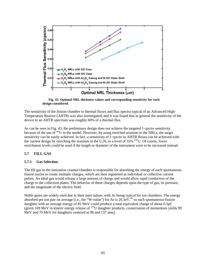
65
Fig. 43. Optimal NRL thickness values and corresponding sensitivity for each
design considered.
The sensitivity of the fission chamber to thermal fluxes and flux spectra typical of an Advanced High-Temperature Reactor (AHTR) was also investigated, and it was found that in general the sensitivity of the device to an AHTR spectrum was roughly 60% of a thermal flux.
As can be seen in Fig. 43, the preliminary design does not achieve the targeted 1 cps/nv sensitivity because of the use of natU in the model. However, by using enriched uranium in the NRLs, the target sensitivity can be easily achieved. In fact, a sensitivity of 1 cps/nv to AHTR fluxes can be achieved with the current design by enriching the uranium in the U2N3 to a level of 35% 235U. Of course, lower enrichment levels could be used if the length or diameter of the instrument were to be increased instead.
5.7 FILL GAS
5.7.1 Gas Selection
The fill gas in the ionization counter/chamber is responsible for absorbing the energy of each spontaneous fission nuclei to create multiple charges, which are then registered as individual or collective current pulses. An ideal gas would release a large amount of charge and would allow rapid conduction of the charge to the collection plates. The behavior of these charges depends upon the type of gas, its pressure, and the magnitude of the electric field.
Noble gases are widely used due to their inert nature, with Ar being typical for ion chambers. The energy absorbed per ion pair on average (i.e., the “W-value”) for Ar is 26.3eV,99 so each spontaneous-fission daughter with an average energy of 85 MeV could produce a total equivalent charge of about 0.5pC (given 169 MeV in kinetic energy release of 235U daughter products, conservation of momentum yields 99 MeV and 70 MeV for daughters centered at 98 and 137 amu).

66
Table 9 compares the range, as computed by TRIM97 of typical fission products for various gases, showing that the range decreases with the atomic number of the noble gas. Also immediately apparent is the fact that, even for Xe, the range exceeds the 5mm spacing between electrodes in the proposed ion chamber. Thus, only a fraction of the full charge possible will be observed, depending upon the direction of the fission product. Since the lineal rate of energy deposition is not uniform, the effect is not a simple proportion. Nevertheless, based upon Table 9 alone, the maximum signal due to the number of ion pairs would be observed by using Xe as the chamber gas.
Table 9. Range of representative fission products for noble gases at standard temperature and pressure
Gas Ionization potential (ev)
Range (cm)
98 amu at 99MeV 137 amu at 70MeV
He 24.6 12.6 11.1
Ne 20.1 4.3 3.8
Ar 15.8 2.4 2.0
Kr 14.0 1.7 1.5
Xe 12.1 1.2 1.0
Proportional counters universally add a quench gas to help prevent avalanche due to the release of photoelectrons and subsequent multiplication in the high electric fields. The fission counter is an ion chamber with lower electric fields, so avalanche is not observed, obviating the need for a quench gas. However, the addition of some gases to the noble gas can produce desirable effects. Excited states in the nonionized noble gas can transfer energy to some gases and cause additional ion pairs to be produced.100 Unfortunately, hydrocarbons, freons, and carbon oxides can break down in ionizing conditions at high temperatures and may lead to problems such as conductive carbon deposits or gaseous species that can capture electrons. Nitrogen is relatively inert but has a high ionization energy (15.5eV)101 and cannot be ionized by excited states of Ar, Kr, or Xe. On the other hand, nitrogen can increase the electron mobility by several times, even at a concentration of less than 1% in argon.102
Although the total charge may be unaffected by the presence of nitrogen, the useful signal may be significantly improved. The drift time of electrons much higher than that of ions due to the electron’s much smaller mass. For a typical ion mobility, µion = 1 cm2·atm/V/s and an electric field, E = 1000 V/cm, the ion drift velocity µion·E/P = 1 m/s for a pressure, P = 1 atm. Thus the ion collection time across 5 mm with an electric field of 1000 V/cm is 500 µs. The mobility of electrons is much higher and typically saturates and decreases at high electric fields. For 0.2% nitrogen in argon, the electron drift velocity is the order of 104 m/s,102 giving an electron collection time of 500 ns under the same conditions. Thus high currents and high counting rates in gas detectors are possible due to electron collection, not ion collection. Consequently, the addition of electron attaching species, such as water or oxygen, would be deleterious for detectors.
To test the actual performance of various gases and gas mixtures, an ion chamber was fabricated and is shown in Fig. 44. Two metal plates, approximately 5 cm square, were separated by 5 mm, identical to the anticipated gap the in the proposed fission counter. The flange is sealed to a vacuum chamber and the

67
plate in the foreground is biased and connected to an external charge-sensitive amplifier. The plate in the background is grounded. To introduce representative fission products, ~0.2 µCi of 252Cf was added to the biased (signal) plate. The fission branch of 252Cf is 3.092%, implying that the source emits ~7000 alphas/s and ~230 fissions/s. Since only half of the particles can enter the gas, the maximum count rate of alpha particles was ~3400/s, while that of fission fragments was ~230/s (there are two fission fragments per fission).
Fig. 44. Parallel-plate ion chamber
for testing performance of various gas mixtures.
Fig. 45 shows the signals generated using an Ortec 142PC preamplifier and an Ortec 472A spectroscopy amplifier (shaper). Signals from alpha-particle absorption are low in amplitude and are clearly separated from the fission product absorption events. A bias of +500 V is used with a 90%Ar/10%N2 mixture at 1atm.
Fig. 46 shows response comparisons of Ar and Kr mixtures acquired by a multichannel analyzer (MCA). The low-energy alpha pulses are at the smaller ones and are clearly separated from the pulses due to higher-energy fission products; the MCA channel is proportional to the magnitude of the charge in each pulse. The integrated count rate above Channel 100 was 126 cps ±1% for all mixtures. As expected, Kr releases more charge than Ar due to its lower ionization energy and shorter range. The addition of nitrogen increases the charge in both cases, possibly because recombination is reduced due to a much faster electron drift velocity. In fact, the rise time is reduced dramatically, as shown in Fig. 47. An Agilent DSO7034B oscilloscope was interfaced to a computer with a MATLAB program that collected 10,000 waveforms for each mixture, which were then analyzed for 10% to 90% rise time and plotted as a histogram.

68
Fig. 45. Photograph of oscilloscope traces showing the
preamplifier output (blue) and shaper output (yellow).
Fig. 46. Multichannel analysis of shaper-amplifier output with various mixtures.

69
Fig. 47. Rise time of preamplifier pulses for various gases.
The results of the initial study, described above, show that the choice of the gas mixture can maximize the signal for pulse counting. Further work with Xe, rare gas mixtures, and nitrogen should be done to ensure that optimum signals for pulse counting can be obtained. Additionally, the relative contribution of signals from alpha absorption should be accounted for in order to create an optimum gas environment for high-neutron-flux current-mode monitoring and well as lower-neutron-flux pulse-counting modes.
5.7.2 Contamination
Besides the obvious possible contamination of the fill gas during fabrication of the fission counter/chamber, self-contamination during operation and infiltration must be considered. Fission products include iodine and other species that could alter the performance or calibration of the fission counter/chamber. Carbon or zeolite absorbents with very high surface area for physisorption and possible chemisorption are candidate materials to lower partial pressures of contaminants. Oxygen and possibly water could act as means to transport carbon within the chamber and must be scrupulously excluded.
5.7.3 Helium Permeation
Influx of high-pressure He (in gas-cooled reactors) must also be considered in the design of the fission counter/chamber. For example, given an alumina shell with a permeability96 at 1073 K of about 1.5 × 10⁻¹¹ cm3/(s·cm·atm), the steady-state permeation of 8 MPa He through a 3 mm thick wall with a ~500 cm2 area is 0.06 L/year. Clearly, contamination by He permeation could be significant and could affect device calibration and operation, if the device design and the selection of materials are not well considered.
The permeation of gases through solid materials is slow in general and proceeds approximately exponentially with distance squared. For one-dimensional diffusion, the exact expression103 of molar concentration as a function of distance, 𝑥, into a semi-infinite solid with a constant diffusivity, 𝐷, is:
𝐶(𝑥, 𝑡) =𝐶𝑒𝑥𝑡𝑒𝑟𝑛𝑎𝑙𝑅𝑇
erfc 𝑥
2√𝐷𝑡, (23)

70
where 𝐶𝑒𝑥𝑡𝑒𝑟𝑛𝑎𝑙 is the external gas concentration, 𝑅 is the universal gas constant, 𝑇 is the absolute temperature and 𝑡 is the diffusion time. Equation (23) assumes that 𝐷 is independent of the concentration and that the solubility is independent of pressure. For an alumina permeability96 at 1073 K of 1.5 × 10⁻¹¹ cm3/(s·cm·atm) at standard temperature and pressure, the diffusivity is 1.5 × 10⁻¹¹ cm2/s. Plots of the concentration relative to the external concentration are shown in Fig. 48, which shows that diffusion proceeds very slowly over a period of years.
Fig. 48. Relative concentration of helium in a semi-infinite block
of alumina for various times after the start of diffusion.
Equation (23) actually underestimates the diffusion, since diffusion is very rapid once the helium reaches the interior wall. For a finite slab of width 𝑊, the concentration can be expressed as a Fourier series:104
𝐶(𝑥, 𝑡) =
𝐶𝑒𝑥𝑡𝑒𝑟𝑛𝑎𝑙𝑅𝑇
𝑊 − 𝑥𝑊
+ 2(−1)𝑛
𝑛𝜋exp −
𝑛𝜋𝑊2𝐷𝑡 𝑠𝑖𝑛
𝑛𝜋(𝑊 − 𝑥)𝑊
𝑛
(24)
Eq. (24) assumes 𝐶(𝑥, 𝑡) = 𝐶𝑒𝑥𝑡𝑒𝑟𝑛𝑎𝑙 for 𝑥 < 0 and 𝑡 > 0, and 𝐶(𝑥, 𝑡) = 0 for 𝑥 > 𝑊 for all time. The flux of helium (amount crossing a unit area per unit time) is
𝐽(𝑥, 𝑡) = −𝐷
𝜕𝐶(𝑥, 𝑡)𝜕𝑥
(25)
Thus,
𝐽(𝑥, 𝑡) =
𝐷𝑊𝐶𝑒𝑥𝑡𝑒𝑟𝑛𝑎𝑙𝑅𝑇 1 + 2(−1)𝑛exp −
𝑛𝜋𝑊2𝐷𝑡 𝑐𝑜𝑠
𝑛𝜋(𝑊 − 𝑥)𝑊
𝑛
(26)
The equivalent volumetric flow across an area A at pressure 𝑃 is
𝐽(𝑥, 𝑡)𝐴𝑅𝑇/𝑃, (27)
71
where R is the universal gas constant. Specifically, the flow across a 500 cm2 area of 3 mm thick alumina at 5 years rises to only ~31 µL/year at 1 atm. In fact, the permeation rate would not achieve steady-state for decades. In the first 10 years of operation, the total influx would be only about 4 mL, an amount that is not expected to significantly alter ion-chamber response. This suggests that helium contamination would not present a significant issue for the ion chamber in its first several years of operation.
5.8 SIZING ANALYSIS
The following is the analysis determining the factor of safety for the fission chamber designed to be used in high-temperature and high-pressure environments, such as in a flowing He coolant at 8 MPa. A sketch of the viable option is shown in Fig. 49. All of the wall dimensions were adjusted to 2.0 mm thickness to withstand the outer pressure experienced when in the pressurized environment. Both the SiC (Hexoloy®) and the alumina had similar mechanical properties, so the thickness of 2.0 mm applies to both. Only the fission chamber tube and end caps were considered in the analysis. All other components were removed in the design. The internal volume of the chamber was conserved for these components.

72
Fig. 49. Fission chamber featuring limited dimensions of the outer shell. (Dimensions in cm).

73
5.8.1.1 Geometry
The only parameter manipulated in the analysis was the thickness of the material, which was universally changed for the entire model for simplicity. The initial thickness was approximately 1 mm, yielding an unviable result. The final thickness of 2 mm should be reviewed to ensure that it is compatible with all of the other system requirements. If possible, a 3 mm wall is recommended to further reduce risk. For the simulation, all three components were fused into a single component (see Fig. 50). This is an acceptable assumption as this analysis evaluates the strength of the bulk material, not the strength of the joint.
Fig. 50. Fission chamber model with 2mm thick walls. The features of the top and bottom interfaces show the merged geometry.
5.8.2 Materials and Methods
SolidWorks 2012 was used in this analysis. The materials used were the SolidWorks stock material alumina and Saint-Gobain Hexoloy, whose properties are shown in Table 10 and Table 11.
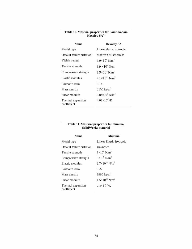
74
Table 10. Material properties for Saint-Gobain Hexoloy SA90
Name Hexoloy SA
Model type Linear elastic isotropic
Default failure criterion Max von Mises stress
Yield strength 3.9×10⁸ N/m2
Tensile strength: 3.9 ×10⁸ N/m2
Compressive strength 3.9×10⁹ N/m2
Elastic modulus 4.1×10¹¹ N/m2
Poisson's ratio 0.14
Mass density 3100 kg/m3
Shear modulus 3.8e×108 N/m2
Thermal expansion coefficient
4.02×10⁻⁶/K
Table 11. Material properties for alumina, SolidWorks material
Name Alumina
Model type Linear Elastic isotropic
Default failure criterion Unknown
Tensile strength 3×10⁸ N/m2
Compressive strength 3×10⁹ N/m2
Elastic modulus 3.7×10¹¹ N/m2
Poisson's ratio 0.22
Mass density 3960 kg/m3
Shear modulus 1.5×10¹¹ N/m2
Thermal expansion coefficient
7.4×10⁻⁶/K

75
For this analysis, it is assumed that the forces on the fission chamber are negligible compared to the external pressure. Radial symmetry is used with sectioning by two orthogonal planes passing through the axis of the chamber. Additionally, the chamber was split in the center to allow for accurate constraining of the last degree of freedom.
Sliding fixtures were used across each symmetry plane as shown in Fig. 51.
Fig. 51 Fixtures used to stabilize the model.

76
An 8 MPa load was applied to all outer surfaces of the shell to simulate the pressurized gas environment as shown in Fig. 52. In the case of the FLiBe environment, the net load would be 0 MPa.
Fig. 52. Loads applied to the model of the fission chamber.
A 1 mm mesh was used for all analyses. A mesh independence study is recommended for the final analysis once the joints are understood. Greater resolution would be desirable in the lower cap to better resolve the stresses in that area, however the mesh in Fig. 53 is sufficient for this sizing exercise.

77
Fig. 53. Mesh detail of the fission chamber model.

78
5.8.3 Results
Factor of Safety (FoS) results are shown and discussed (FoS is how many times stronger the material is than it has to be in order to not yield). Typical FoSs for engineering design are 3. Since both of these materials are brittle materials (ceramics) the Mohr-Coulomb failure criteria were used.
5.8.3.1 SiC Hexoloy® A
Minimum FoS is 2 with all stress concentrations along edges and no stress concentrations penetrating the entire wall. The distribution is shown in Fig. 54.
Fig. 54. Factor of safety results for SiC Hexoloy SA.
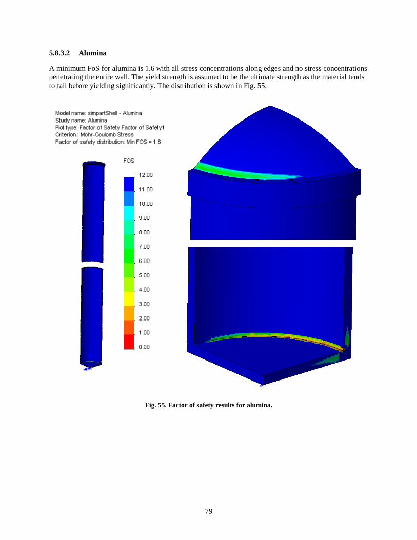
79
5.8.3.2 Alumina
A minimum FoS for alumina is 1.6 with all stress concentrations along edges and no stress concentrations penetrating the entire wall. The yield strength is assumed to be the ultimate strength as the material tends to fail before yielding significantly. The distribution is shown in Fig. 55.
Fig. 55. Factor of safety results for alumina.

80
5.8.4 Conclusions
A wall thickness of 2 mm will be sufficient for a design based on alumina or SiC structural materials while a thickness of at least 3 mm is preferred.
For wall a wall thickness of 2 mm:
• FoS (minimum) for alumina = 1.6 • FoS (minimum) for silicon carbide = 2
Further analysis is needed for the final design, but these results will be adequate for the sizing of the caps and tube. It will be important to pay attention to the bonding techniques used between the components and the resulting stresses resulting from differential thermal expansion.
5.9 CHAMBER RECOMMENDATION
The chamber presents significant design challenges, the most significant of which are the temperature and the chemical environment in which it must operate. Temperature considerations eliminate any organic materials, such as plastics, and all aluminum alloys. After evaluation of the properties of candidate metals, nickel alloys appear to offer the best mechanical and thermal characteristics. However, it will be necessary to coat nickel alloys with pure nickel to avoid having alloy constituents react with molten FLiBe. Among the nonmetals, SiC appears to offer the best properties for the outer environmental sheath because it is impervious to He gas and, very importantly is not attacked by FLiBe. However, brazes suitable for joining SiC to itself and to MI cable (sheath and feed-throughs) need to be evaluated because the very inertness of SiC inhibits wetting by molten metal. It may also be possible to construct the outer sheath of the chamber from an alumina mandrel onto which a nickel-coated nickel alloy is formed. This scheme has the advantage of allowing a thinner nickel skin to serve as the barrier between FLiBe and the alumina (which is attacked by FLiBe) while the alumina mandrel provides the structural strength. A chamber constructed with any of these options as the environmental barrier will be able to achieve 1 cps/nv and would be expected to operate over the 13 orders of magnitude of flux specified.
The best choice of insulator material is alumina. This material is inert with respect to the fill gas, and its resistivity remains high even at 1073 K. Irradiation stability of Al2O3 to the expected fluences do not create limitations on strength with volumetric swelling, which in the case of sapphire can be isotropic, will be well below 1%. Joining alumina to alumina and to metals is accomplished by the moly-manganese technique, which is well established, but these joints must be protected from contact with FLiBe. Single-crystal sapphire may be preferred over polycrystalline Al2O3 because grain boundaries may act as sites at which the nitrogen in the fill gas can attack the insulator.
A viable fill gas is Ar-1%N2. Experience with this mixture has shown that it has appropriate electron and ion transport properties and it is easily obtained. The main disadvantage is that nitrogen reacts with carbon at 1073 K. Mixtures of nonreactive noble gases with small amounts of nitrogen are also viable. Kr may replace Ar, as shown in Fig. 47, but the effects of Kr isotopes with high-thermal-capture cross sections on chamber efficiency need to be evaluated. In parallel with evaluation of candidate structural materials, careful measurement of transport properties and stopping power of noble gas mixtures must be performed.
Electrodes can be either metal cylinders or coatings on alumina forms. The latter has the advantage of constructing the entire chamber with a single material and thus avoiding issues of CTE mismatch. It has the disadvantage of implementing thin film electrodes that must conduct up to 434 W of heating to the

81
reactor coolant. On the other hand, solid metal cylinders have lower thermal resistance and will be better able to handle the heat load. We recommend the use of solid metal cylindrical electrodes.
Based on the analysis in Section 4, we recommend the neutron-reactive layer to be uranium nitride. This material is more conductive than the oxide and does not react with the nitrogen in the fill gas. Higher conductivity is desirable to improve the electrical characteristics of the chamber, and this property alone is sufficient to continue its evaluation.
In summary, we recommend evaluation of SiC, alumina (polycrystalline and sapphire), and nickel alloys (coated and uncoated) as structural materials. The fill gas of choice is Ar-1%N2, although substituting Kr or Xe for Ar is not out of the question. Electrodes should be fabricated from solid nickel alloy rather than film deposited on an alumina base so that the heat load can be effectively dissipated. Uranium nitride is an attractive sensitizing material, although if subsequent testing demonstrates poor adhesion or difficulties in electroplating, the oxide should replace it.
82
6. REFERENCE
1 K. H. Valentine, J. T. De Lorenzo, W. T. Clay, V. K. Paré, G. C. Guerrant, R. S. Burns, Experimental Study of Fission Counter Design Optimization with a Simplified Analytical Model of Performance, ORNL/TM-6926, Oak Ridge National Laboratory, Oak Ridge, Tenn., December, 1979.
2 Glenn Knoll, Radiation Detection and Measurement, 3rd Ed., John Wiley and Sons, New York, p. 133. 3 Glenn Knoll, op. cit., p. 182. 4 Glenn Knoll, op. cit., p. 159. 5 K. H. Valentine et al., “Development of a high-Temperature High-Sensitivity Fission Counter for LMR
In-Vessel Flux Monitoring,” “Specialists Meeting On Instrumentation And Reactor Core Assessment”, Cadarache, France, June 7-10, 1988.
6 Glenn Knoll, op. cit., p. 526. 7 Athanasios Papoulis, Probability, Random Variables, and Stochastic Processes, 2nd Ed., McGraw Hill,
p. 285. 8 Glenn Knoll, op.cit., p. 107. 9 Veljko Radeka, “Pulse Processing Overview”, IEEE NSS Short Course Notes. (2002). 10 K. H. Valentine, M. K. Kopp, and J. A. Williams, “Feedback Threshold Control Extends Pulse Rate
Measurements Into the Pileup Region,” IEEE Trans. Nucl. Sci., Vol. NS-34, No. 1, Feb. 1987, pp. 78-81.
11 K. H. Valentine, R. L. Shepard, K. G. Falter, and W.B. Reese “Development of a 10-Decade Single-Mode Reactor Flux Monitoring System”, In Core Instrumentation and Reactor Assessment Proceedings of a Specialists' Meeting, Cadarache, France, June 7-10, 1988 Nuclear Energy Agency Organization of Economic Cooperation and Development.
12 This can be found in any text on transmission lines. 13J. T.De Lorenzo, W. T. Clay, G. C. Guerrant, “Differential Current Pulse Preamplifier for Fission
Counters,” IEEE Trans. Nucl. Sci. February 1974, Volume NS-21, Number 1. 14 M. K. Kopp and K. H. Valentine, “Paralleling of Preamplifier Input Stages for a Low-Noise, Wideband
Termination of Low-Impedance Transmission Lines,” IEEE Trans. Nucl. Sci., Vol. NS-32, No. 1, Feb. 1985, pp. 68-70.
15 L. D. Philipp, N. C Hoitink, W. G. Spear, and M. R. Wood, “Effects of Gas Mixture, Electrode Spacing, Gas Pressure, and Applied Voltage On the Gamma Performance of Fission Counters,” Nuclear Technology, Vol. 20, 1973, pp. 51-59.
16 US Patent 4,493,811. 17 Joseph M. Harrer and James C. Beckerley Eds., Nuclear Power Reactor Instrumentation Systems
Handbook, USAEC, May, 1973, Chapter 5. 18 Maeck, William J. “System for Total Iodine Retention.” US Patent 3,658,467, 1969. 19 A. F. Tavassoli, J. Nucl. Mater. 302 (2002) 73. 20 S.J. Zinkle, N.M. Ghoniem, Fusion Eng. and Design, 51-52 (2000) 55. 21 R.L. Huddleston, R.W. Swindeman, “Materials and Design Bases issues in ASME Code Case N-47,”
NUREG/CR-5955, ORNL/TM-12266, April 1993. 22 S.J. Zinkle, L.J. Ott, D.T. Ingersoll, R.J. Ellis, M.L. Grossbeck, “Overview of materials technologies for space
nuclear power and propulsion”, AIP Conf. Proc., Space Technology and Applications International Forum-STAIF 2002, vol. 608 (2002) 1063-1074.
23 Special Metals technical bulletin on MA956, Special Metals Corporation (2004). 24 M. S. El-Genk, J-M. Tournier, J. Nucl. Mater. 340 (2005) 93.

83
25 J.T. Busby, C.E. Duty, K.J. Leonard, R.K. Nanstad, S.J. Pawel, M. Sokolov and S.J. Zinkle,
“Assesment of structural and clad materials for fission surface power systems”, ORNL report ORNL/LTR/FSP/07-XX, Oak Ridge National Laboratory, Oak Ridge, TN, August 2007.
26 Liquid-Metals Handbook, R. N. Lyon, Ed. In Chief, NAVEXOS P-733 (Rev.), Atomic Energy Commission, June 1952.
27 R.S. Reid, T.J. Sena, A.L. Martinez, “Heat-pipe development for advanced energy transport concepts”, Final Report Covering the Period January 1999 through September 2001, LANL report LA-13949-PR, Los Alamos, NM, October 2002.
28 J.J. Fischer, U.S. Patent 4075010, International Nickel Company, New York, NY, February 21, 1978. 29 B. El-Dasher, J. Farmer, J. Ferreira, M. Serrano de Caro, A. Rubenchik, A. Kimura, J. Nucl. Mater. 419
(2011) 15. 30 J. Leary and H. Kittle, Advanced LMFBR fuels”, ANS Topical Meeting Proceedings, ERDA-4455,
Tucson, Arizona (1977). 31 G.L. Hoffman, “Preliminary assessment of fuel R&D for the initial space fission power system concept
set”, SPFT workshop, Argonne National Laboratory, April 2001. 32 J.D.B. Lambert and R. Strain, Oxide Fuels, in B.R.T. Frost (ed.) Material Science and Technology, vol.
10A, VCH Publishers, New York, NY (1994). 33 J.F. Bates, M.K. Korenko, Nucl. Technol. 48 (1979) 303. 34 E.E. Bloom, S.J. Zinkle, F.W. Wiffen, J. of Nucl. Mater. 329-333 (2004) 12. 35 H. Ullmaier, Nucl. Fus., 24 (1984) 1039. 36 J. Schroeder, H. Ullmaier, J. of Nucl. Mater. 179-181 (1991) 118. 37 D.S. Gelles, J. Nucl. Mater., 233-237 (1996) 293. 38 a) B.V. Cockeram, R.W. Smith, K.J. Leonard, T.S. Byun, L.L. Snead, J. Nucl. Mater. 382 (2008) 1. (b)
B.V. Cockeram, R.W. Smith, L.L. Snead, J. Nucl. Mater. 346 (2005) 165. 39 K.J. Leonard, “Radiation Effects in Refractory Metals and Alloys”, in Comprehensive Nuclear
Materials, ed. R.J.M. Konings, Elsevier Publishing, Amsterdam, vol. 4, (2012) 181-213. 40 K.J. Leonard and S.J. Zinkle, “Evaluation of vanadium-base alloys for space nuclear applications”, in
report ORNL/LTR/NR-JIMO/04-08, (2004). 41 (a) K.J. Leonard, C.E. Duty, S.J. Zinkle, R.F. Luther, R.E. Gold, R.W. Buckman, “Niobium-base
Alloys for Space Nuclear Applications”, Proceedings of the Space Nuclear Conference, San Diego, CA, June 5-9, (2005) 286. (b) K.J. Leonard, J.T. Busby, D.T. Hoelzer, S.J. Zinkle, Met. and Mater. Trans. A., 40, 4 (2009) 838.
42 S.J. Zinkle, F.W. Wiffen, “Radiation effects in refractory alloys”. in STAIF 2004, AIP Conference Proceedings; El-Genk, M. S., Ed.; vol. 699 (2004) 733–740.
43 K.J. Leonard, J.T. Busby, S.J. Zinkle, J. Nucl. Mater., 414, 2 (2011) 286. 44 F.W. Wiffen, “Creep and tensile properties of helium injected Nb-1%Zr”, in Radiation Effects and
Tritium Technology for Fusion Reactors, vol. II, Watson J.S.; Wiffen F.W. Eds., CONF-750989, Gatlinburg, TN (1976) pp. 344-361.
45 A.A. Sauges, J. Auet, “Mechanical behavior of Nb-1%Zr implanted with He at various temperatures”, in Radiation Effects and Tritium Technology for Fusion Reactors, vol. II, Watson J.S.; Wiffen F.W. Eds., CONF-750989, Gatlinburg, TN (1976) pp. 331-343.
46 J.R. Remark, A.B. Johnson, H. Farrar, D.G. Atteridge, Nucl. Technol., 29 (1976) 369. 47 P.J. Ring, E.D. Sayre, “Materials Requirements, Selection and Development of the Proposed JIMO
Space Power System”, AIP Conf. Proc., Space Technology and Applications International Forum-STAIF 2004, vol. 699 (2004) 806-814.
48 W.J. Carmack, D. L. Husser, T.C. Mohr, W.C. Richardson, “Status of Fuel Development and Manufacturing for Space Nuclear Reactors at BWX Technologies” AIP Conf. Proc., Space Technology and Applications International Forum-STAIF 2004, vol. 699 (2004) 426-431.

84
49 J.M. Blocher Jr, N.D. Veigel, J.H. Oxley, V.M. Secrest, E.E. Rose, “Fluidized-bed Coating of UO2
Powder with Niobium and Other Elements”, Battelle Memorial Institute, Columbus, OH, Report number BMI-1440, May 25, 1960.
50 A. Glassner, “The Thermochemical Properties of the Oxides, Fluorides and Chlorides to 2500K”, Argonne National Laboratory report ANL-5750, January 1, 1957.
51 D.L. Keller, G.W. Cunningham, W.E. Murr, E.O. Fromm, D.E. Lozier, “High Temperature Irradiation Test of UO2 Cermet Fuels”, Battelle Memorial Institute, Columbus, OH, report BMI-1608, January 7, 1963.
52 M. Kangilaski, E.O. Fromm, D.H. Lozier, V.W. Storhok, J.E. Gates, “High-Temperature Irradiation of Nb-1Zr Clad UO2”, Battelle Memorial Institute, Columbus, OH, report BMI-1730, June 28, 1965.
53A.U. Buatti, J.W. Schmitt, “Design and Study of a High Power In-Pile Nuclear Thermionic Space Power Plant”, Pratt and Whitney, East Hartford, CT, report PWA-2351, volume 2, appendix 8, January 1, 1965.
54 J.L. Laidler, J.J. Holmes, J.W. Bennett, U.S. Programs on Reference and Advanced Cladding/Duct Materials, International Conference: Radiation Effects in Breeder Reactor Structural Materials. American institute of Mining, Metallurgical and Petroleum Engineers, (1977) 41-52.
55 T.S. Byun, K. Farrell, J. Nucl. Mater. 318 (2003) 292. 56 B.H. Sencer, G.M. bond, F.A. Garner, M.M. Hamilton, S.A. Maloy, W.F. Somer, J. Nucl. Mater. 296
(2001) 145 57 J.D. Hunn, E.H. Lee, T.S. Byun, L.K. Mansur, J. Nucl. Mater. 296 (2001) 2003. 58 K.J. Leonard, unpublished data. 59 T.M. Angeliu, J.T. Ward, J.K. Witter, “Assessing the effects of radiation damage on Ni-base alloys for
the Prometheus space reactor system”, Knolls Atomic Power Laboratory Report, LM-06K033, Schenectady, NY, April 4, 2006.
60 A.F. Rowcliffe, “Irradiation Performance of Nickel-Base Superalloys”, chapter 3, in Critical Assessment of Structural Materials for Space Nuclear Applications, Oak Ridge National Laboratory Report ORNL/LTR/NR-JIMO/04-08, (2004).
61 N.I. Budylkin, E.G. Mironova, V.M. Chernov, V.A. Kranoselov, S.I. Porollo, F.A. Garner, J. Nucl. Mater. 375 (2008) 359.
62 J.O. Stiegler, L.K. Mansur, Ann. Rev. Mater. Sci., 9 (1979) 405. 63 N.H. Packan, K. Farrell, J.O. Stiegler, J. Nucl. Mater. 78 (1978) 143. 64 R.M. Boothby, J. Nucl. Mater., 230 (1996) 148. 65 J.I. Bramman, C. Brown, J.S. Watkins, C. Cawthorne, E.J. Fulton, P.J Barton, E.A. Little, Void
Swelling and Microstructural Changes in Fuel Pin Cladding and Unstressed Specimens Irradiated in DFR. International Conference: Radiation Effects in Breeder Reactor Structural Materials, The Metallurgical Society of AIME (1977) 479-507.
66 J.S. Watkins, J.H. Gittus, J. Standring, The Influence of Alloy Constitution on the Swelling of Austenitic Stainless Steels and Nickel Based Alloys, International Conference: Radiation Effects in Breeder Reactor Structural Materials, The Metallurgical Society of AIME (1977) 467-477.
67 R.M. Boothby, J. Nucl. Mater. 171 (1990) 215. 68 R.M. Boothby, J. Nucl. Mater. 171 (1990) 215. 69 G.H. Broomfield, “High temperature Tensile Properties of Thermal Reactor Irradiated Nimonic PE-16”,
in Irradiation Effects in Structural Alloys for thermal and Fast Reactors, ASTM STP 457 (1965) 38-67. 70 H.J. Busboom and P.W. Mathay, Fast Neutron Damage Studies in High Nickel Alloys, General Electric
Atomic Power report, GEAP-4985, AEC Research and Development Report (1966). 71 R.M. Boothby, J. Nucl. Mater. 186 (1992) 209. 72 B.A. Thiele, F. Schubert, H. Derz, G. Pott, J. Nucl. Mater. 171 (1990) 94. 73 J. Barnaby, P.J. Barton, R.M. Boothby, A.S. Fraser, G.F. Slattery, “The Post-Irradiation Mechanical
Properties of AISI Type 316 Steel and Nimonic PE16 Alloy”, Proceedings of the International

85
Conference: Radiation Effects in Breeder Reactor Structural Materials, The Metallurgical Society of AIME (1977) 159-175.
74 J.R. Lindgren, Nuclear Technology, 66 (1984) 607. 75 T. Yamamoto, G.R. Odette, P. Miao, D.T. Hoelzer, J. Bentley, N. Hashimoto, H. Tanigawa, R.J. Kurtz,
J. Nucl. Mater. 367–370 (2007) 399. 76 J. Gan and B.A. Hilton, “TEM Examination of Advanced Alloys Irradiated in ATR”, Idaho National
Laboratory report INL/EXT-07-13306, September 2007. 77 J.H. DeVan, J.R. DiStefano, W.P. Eatherly, J.R. Keiser, R.L. Klueh, “Materials Consideration for
Molten Salt Accelerator-based Plutonium Conversion Systems”, AIP Conf. Proc., 346, (1995) 476-487. 78 G.O. Hayner et al., “Next Generation Nuclear Plant Materials Research and Development Program
Plan”, Idaho National Laboratory Report, INL/EXT-06-11701, rev 3, August 2006. 79 S-H. Cho, J-M Hur, C-S Seo, Ji-S Yoon, S-W Park, J. of Alloys and Compounds, 468 (2009) 263-269. 80 Special Metals technical bulletin on MA754, Special Metals Corporation (2004). 81 G.Y. Lai, Chapter 4, in High Temperature Corrosion and Materials Applications, ASM International,
Materials Park, OH, (2007) pp. 67-92. 82 Z.W. Bell, C.L.Britton Jr., C.I. Contescu, D.E. Holcomb, M.J. Lance, L.K. Mansur, L.F. Miller, E.K.
Ohriner, M.D, Pawel, J.A. Williams, “Fission Chamber Development”, Oak Ridge National Laboratory Report ORNL/LTR/NR-PROM1/05-17, July 2005.
83 M.S.A. Karunaratne, P. Carter, R.C. Reed, Mat. Sci. and Eng. A, 281, 1-2 (2000) 229. 84 http://www.hexoloy.com, accessed August 20, 2012. 85 L.L. Snead, T. Nozawa, Y. Katoh, T.S. Byun, S. Kondo, D.A. Petti, Handbook on SiC Properties for
Fuel Performance Modeling, J. Nucl. Mater., 371 (2007) 329-377. 86 Y. Katoh, L.L. Snead, I. Szlufarska, W.J. Weber, Radiation Effects in SiC for Nuclear Structural
Applications, Current Opinion in Solid State & Materials Science, 16 (2012) 143-152. 87 D. Wilson, Oak Ridge National Laboratory, private communication to Y. Katoh, August, 2012. 88 L.L. Snead, Limits on irradiation-induced thermal conductivity and electrical resistivity in silicon
carbide materials, J. Nucl. Mat. 329-333 (2004) 524-529. 89 L. L. Snead, M. Osborne, K. L. More, Effects of radiation on SiC-based Nicalon fibers, J. Mater. Res.
10 (1996) 736. 90 http://www.hexoloy.com/hexoloy-sic-physical-properties, accessed August 20, 2012. 91 Dow Chemical CVD Silicon Carbide technical data. 92 Y. Katoh, S. Kondo, L.L. Snead, DC Electrical Conductivity of Silicon Carbide Ceramics and
Composites for Flow Channel Insert Applications, J. Nucl. Mater., 386 (2009) 639-642. 93 NIST Standard Reference Data Program, http://www.nist.gov accessed on 1/4/2005. 94 G.P. Pells and B.C. Sowden, “The electrical conductivity of sapphire irradiated at 550-700°C with an
applied electric field of 1 kV/cm,” J. Nuclear Mater. 223 pp.174-9 (1995). 95 D. M. Mattox and H. D. Smith, “Role of Manganese in the Metallization of High Alumina Ceramics,”
Am. Ceram. Soc. Bull., 64 [10] pp.1363-67 (1985). 96 W. G. Perkins, “Permeation and Outgassing of Vacuum Materials,” J. Vac. Sci. Technol., 10 [4]
pp.543-56 (1973). 97 The TRIM code is available gratis at www.srim.org. 98 MCNP – Monte Carlo N-Particle code, version 5. Available from the Radiation Safety Information
Computational Center, Oak Ridge National Laboratory, Oak Ridge, Tenn. 99 Glenn Knoll, op. cit., p. 176. 100 Hurst, G.S., T.E. Bortner, and R.E. Glick. (1965) “Ionization and Excitation of Argon with Alpha
Particles.” J. Chem. Phys. 42(2) 713-9. 101 Glenn Knoll, op. cit., p. 130. 102 Bortner T.E., G.S. Hurst, and W.G. Stone. (1957) “Drift Velocities of Electrons in Some Commonly
Used Counting Gases.” Rev. Sci. Instrum. 28 (2) 103-8.

86
103 J. Crank, The Mathematics of Diffusion, Clarendon Press, Oxford, 1975. 104 W.E. Starzak (1984) The Physical Chemistry of Membranes, Acad. Press: Orlando. p.216.