Fishing Boat Desigand Cost
65
-
Upload
lukman-tarigan-sumatra -
Category
Documents
-
view
44 -
download
3
description
Ship Costing
Transcript of Fishing Boat Desigand Cost


Fishing boat designs: 4 FAOFISHERIES
TECHNICALPAPER
Small steel 239
fishing boats
Prepared by
David J. Eyres*
Rshenes Technology Service
Fishery industries Division
FOODAND
AGRICULTUREORGANIZATION
OF THE
UNITED NATIONS
Rome, 1984

The designations employed and the presentation
of material in this publication do not imply the
expression of any opinion whatsoever on the
part of the Food and Agriculture Organization
of the United Nations concerning the legal
status of any country, territory, city or area or
of its authorities, or concerning the delimitation
of its frontiers or boundaries.
M-41
ISBN 92-5-102108-2
All rights reserved. No part of this publication may be reproduced,
stored in a retrieval system, or transmitted in any form or by any means,
electronic, mechanical, photocopying or otherwise, without the prior
permission of the copyright owner. Applications for such permission,
with a statement of the purpose and extent of the reproduction, should
be addressed to the Director, Publications Division, Food and Agriculture
Organization of the United Nations, Via delle Terme di Caracalla, 00100
Rome, Italy.
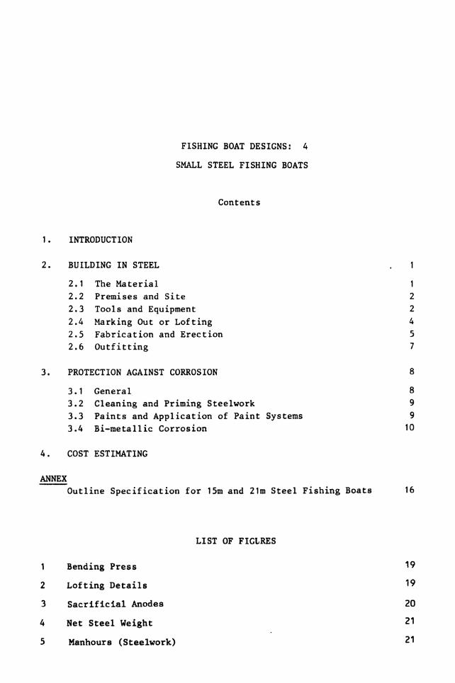
ill
PREPARATION OF THIS PAPER
The paper contains designs of two general purpose steel fishing boats and generalguidance on boatbuilding in steel plus cost estimating for fisheries officers, vesselowners and boatbuilders having experience in working with other materials.
Acknowledgement is made to G. Breekveldt, Marine Architects Ltd., P.O. Box 2642,Auckland, New Zealand, for the designs shown and Adriana Barcali and Maurizio Carlesifor draughting and layouts.
* Present address: c/o Marine Division
Ministry of TransportPrivate Bag
Wellington, No. 2
ABSTRACT
This, the fourth of the FAO fishing boat design handbooks,deals with the subject of small steel fishing boats.
The publication is intended to serve individuals and com-
panies with experience of structural steel fabrication, boat-builders working with other materials who may wish to build
larger craft in steel, and finally fisheries officers and vessel
owners who require guidance on boatbuilding in this material.
Section 2 describes the material, the building site and
tools required, fabrication and outfitting of steel boats.
Section 3 contains information on protection against cor-
rosion and Section 4 presents a simple method of cost estimatingto construct a small steel craft.
The handbook also contains designs of 15 m and 21 m general
purpose steel fishing boats. These consist of general arrange-
ments, lines and hull construction drawings, steel quantitiesand outline specifications.
Distribution: For bibliographic purposes this document
should be cited as follows:
FAO Fisheries DepartmentFAO Regional Fishery Officers Eyres, D.J., Fishing boat designs: 4. Small
FAO Fisheries Field Projects 1984 steel fishing boats. FAO Fish.
Selected Boatbuilders and Naval Architects Tech. Pap., (239): 33 p.

FISHING BOAT DESIGNS: 4
SMALL STEEL FISHING BOATS
Contents
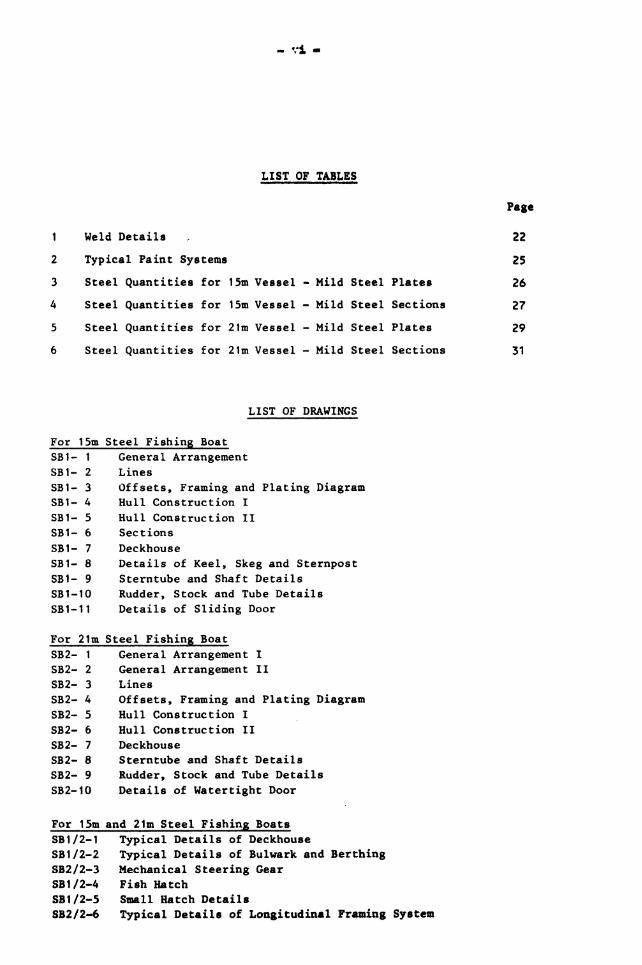
1 . INTRODUCTION
2. BUILDING IN STEEL . 1
2.1 The Material 1
2.2 Premises and Site 2
2.3 Tools and Equipment 2
2.4 Marking Out or Lofting 4
2.5 Fabrication and Erection 5
2.6 Outfitting 7
3. PROTECTION AGAINST CORROSION 8
3.1 General 8
3.2 Cleaning and Priming Steelwork 9
3.3 Paints and Application of Paint Systems 9
3.4 Bi-metallic Corrosion 10
4. COST ESTIMATING
ANNEX
Outline Specification for 15m and 21m Steel Fishing Boats 16
LIST OF FIGIRES
1 Bending Press 19
2 Lofting Details 19
3 Sacrificial Anodes 20
4 Net Steel Weight 21
5 Manhours (Steelwork) 21
- vt -
LIST OF TABLES
Page
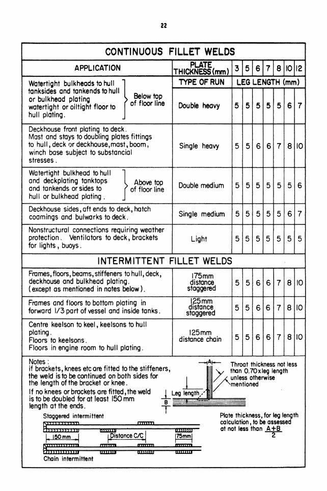
1 Weld Details , 22
2 Typical Paint Systems 25
3 Steel Quantities for 15m Vessel - Mild Steel Plates 26
4 Steel Quantities for 15m Vessel - Mild Steel Sections 27
5 Steel Quantities for 21m Vessel - Mild Steel Plates 29
6 Steel Quantities for 21m Vessel - Mild Steel Sections 31
LIST OF DRAWINGS
For 15m Steel Fishing Boat
SB1- 1 General ArrangementSB1- 2 Lines
SB1- 3 Offsets, Framing and Plating DiagramSB1- 4 Hull Construction I
SB1- 5 Hull Construction II
SB1- 6 Sections
SB1- 7 Deckhouse
SB1- 8 Details of Keel, Skeg and SternpostSB1- 9 Sterntube and Shaft Details
SB1-10 Rudder, Stock and Tube Details
SB1-11 Details of Sliding Door
For 21m Steel Fishing Boat
SB 2- 1 General Arrangement I
SB2- 2 General Arrangement II
SB2- 3 Lines
SB2- 4 Offsets, Framing and Plating DiagramSB2- 5 Hull Construction I
SB2- 6 Hull Construction II
SB2- 7 Deckhouse
SB2- 6 Sterntube and Shaft Details
SB2- 9 Rudder, Stock and Tube Details
SB2-10 Details of Watertight Door
For 15m and 21m Steel Fishing Boats
SB 1/2-1 Typical Details of Deckhouse
SB1/2-2 Typical Details of Bulwark and BerthingSB2/2-3 Mechanical Steering Gear
SB1/2-4 Fish HatchSB I/2-5 Small Hatch Details
SB2/2-6 Typical Details of Longitudinal Framing System
1. INTRODUCTION
This publication in the FAO Fishing Boat Design series deals with the constructionof small steel fishing boats. By small steel boats is meant fishing vessels of less thansay 30 metres overall length where the required building facilities and equipment aremodest and the construction techniques somewhat different from those of larger shipbuildingpractice. Generally the construction of boats in steel is not considered below say 12metres in length where steel is at a weight disadvantage and below 15 metres in the caseof tropical marine conditions because of corrosion rates on the thinner steel plate used.The design of two different general purpose steel fishing boats of 15 m and 21 m overalllength are presented.
Simple hull forms are utilized to avoid the use of sophisticated equipment andskills and the text provides information on the material and its maintenance, the neces-sary building equipment and the important principles which differentiate steel boatbuildingfrom general steel fabrication practices. It is not the intention to teach the basicskills of welding and gas cutting, a knowledge of which is assumed and is not uncommon in
developing countries. The purpose of the publication is rather to show how these skillscan be adapted to steel boatbuilding. Detailed information on construction techniques is
not within the scope of the booklet and the notes are necessarily brief, but an attempthas been made to cover the more important points and the drawings contain a great deal of
extra detail to help the inexperienced builder.
For steel hulls of less than 30 m in length, the equipment and building facilities
required are modest and can be compared with the traditional wood boatyard rather than
the highly automated steel shipyards producing larger vessels.
Notes on estimating steel weights and costs of steel fishing boats are also included.
Finally the layouts of the two designs presented are discussed in detail.
The two steel fishing vessel designs may be suitable for various fishing operationswithin the Exclusive Economic Zones (EEZs) of selected developing countries but should
be adapted to local fishing conditions. For practical reasons full working drawings and
details of construction could not be included in this paper. The designs comply with
the FAO/ILO/IMO Guidelines for the Design, Construction and Equipment of Small Fishing
Vessels, published by IMO. Scantlings are in accordance with good practice for this
size of craft and should meet the requirements of most regulating authorities. The
Organization, however, takes no responsibility that this will be the case and the onus
is on the builder to meet his legal responsibilities for plan approval and survey where
this is necessary.
It is also recommended that safety precautions specific to steel fabrication,erection and outfitting be followed during the construction of the boats. Guidelines
from the ILO publication "Safety and Health in Shipbuilding and Ship Repairing" should
be followed.
2. BUILDING IN STEEL
2.1 The material
Steel as a building material for boats is strong and easy to work. Welded Joints
are equal in strength to the basic material if welders have sufficient skills and some
practice in making watertight structures. It is also easy to repair by cutting out and
welding in new material using facilities available, almost anywhere. Steel does not bumand will last for a long time providing proper protection against rusting is maintained.
Small craft, mainly these 15 m length overall, with thin steel plates, are very
sensitive to corrosion especially in tropical conditions. They need constant and time
consuming maintenance by regular rotational cleaning and repainting of the parts of the
hull subject to rust attack. Precaution against corrosion on the immersed parts of the
hull require the boat to be put ashore frequently for cleaning and maintenance. The
less accessible areas of the steel structure are troublesome to protect and require care
both during the daaign and construction phaaae to Avoid the formation of inaccessibleruat braading pockata, High maintenance coata of tha hull in tropical anvironmanti ahouldba taken into conaidaration bafora a daciaion on conatruction of a ataal fishing boat iamade.
A wida ranga of ataala ara marketed in tha form of plataa and a variaty of sections,For boatbuilding, plain low carbon ataala which ara raaaonably pricad and raadily availablein most countries are more than adequate. It ia recommended that the boatbuildar ordarafrom the ateel supplier hot rolled mild steel plate and sections complying with BritishStandard BS 4360, Japanese Standard JIS G3101 or US Standard ASTM A131-74 or equivalentstandards.
If a boat is designed to the rules of a particular regulating authority or classifi-cation society, this should be clearly stated when ordering material to meet the chemicaland physical properties required by the rules. Such rules should then be observed duringthe design, construction and trials of the boat.
Sections required for the two designs in this publication are limited to flat barsand equal or unequal angles with some hollow rolled sections. There is no reason for theboatbuilder to use a wide variety of sections.
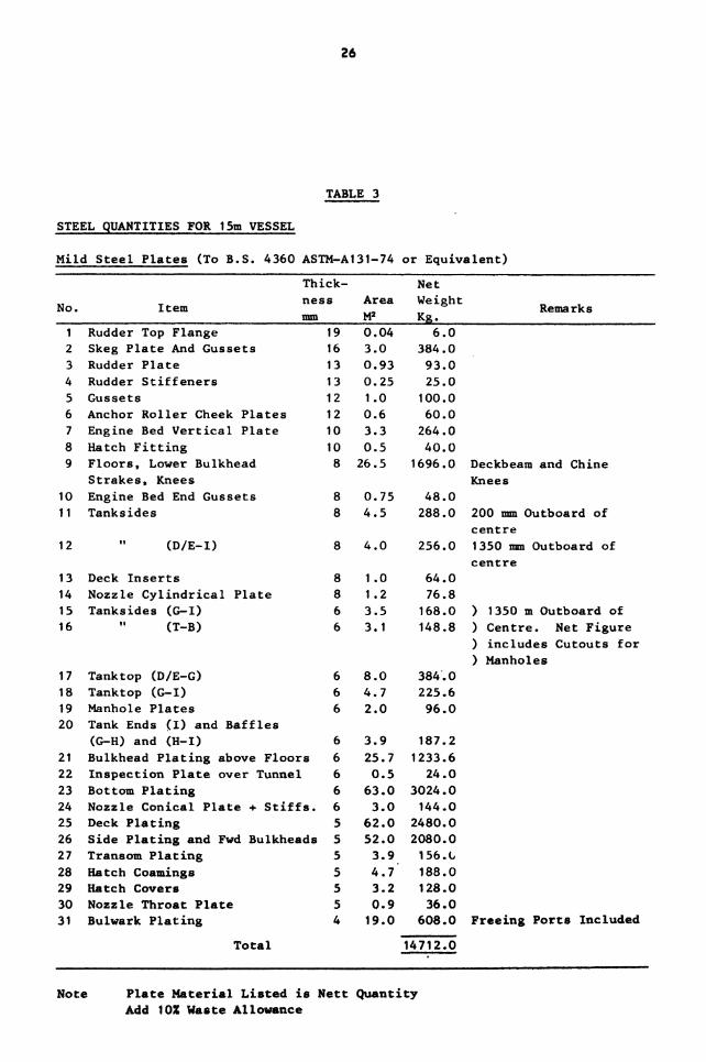
A list of steel materials for the 15 m and 21 m designs in the handbook is given inTables 3, 4, 5 and 6. The quantities listed are net quantities and the percentages to beadded to give the quantity to be ordered are indicated below the tables. When orderingplates for the hull and deck it is good small steel boatbuilding practice to order the
largest size of plate that can be handled to reduce waste and cut down the amount of
working and welding required. The wastage figures given with the tables are based onthis assumption and if for some reason you are not able to utilize the largest plates,add another 5 percent for wastage. Study the plate line body plan and deck plans anddecide how the largest available plates may be utilized before ordering. Also plan thecutting of floors, brackets, etc., from standard plates to avoid excessive waste.
It is advisable to inspect the steel on arrival for defects particularly the platesfor flatness and delaminations. Reject any material that is not satisfactory and couldgive trouble during fabrication and erection. Steel plates and profiles should be stored
properly to avoid bending under their own weight and material should be kept in sorted
packages for easy access.
2.2 Premises and site
Ideally the hull should be built within covered premises protected from the weather.However, this is not always possible and temporary protection may need to be providedfor the critical welding operations during unfavourable climatic conditions.
The vessel should be erected on ground which can support its weight and which mayneed reinforcing for this purpose. It is preferable that the erection site be adjacentto water unless very heavy lift and transport facilities are available.
If a number of vessels are to be built as a new enterprise the installation of a
permanent launching way may be justified. This can be done for end launching by level-
ling a gradient of about 1 in 10 reinforcing the surface and arranging launching railsto below the low water mark. The expense of fabricating a permanent steel cradle to
support the vessel during construction and for subsequent launching may also be justi-fied. For a
fone-off 1
construction, unless a heavy lift is available, temporary but
adequate means of support and' launching should be considered before commencing building.
2.3 Tools and equipment
The tools and equipment required for a small steel boatyard are not extensive andneed not coat any more than those required for a comparable wooden boatyard. If generalsteel fabrication is already undertaken, then the additional equipment is minimal.
2.3.1 Steel cutting equipment
For this purpose one or two oxygen/acetylene hand torch sets are sufficient for thesize of boats covered by this publication. Some items of this equipment should be speciallyselected for boatbuilding use. The torch should be a combination unit so that tips forother purposes than cutting cep be used. A light torch with tip at right angles to thehandle is the most suitable. A two stage regulator is preferable to a single stage regu-lator. There should be sufficient length of hose to reach any part of the boat duringconstruction with the gas bottles remaining on the ground. A light hose is preferred for
this purpose and should be that manufactured for this purpose and supplied with the cuttingequipment. A hand cart for transporting the gas cylinders will be found useful.
2.3.2 Welding equipment
The first consideration relates to the availability of an electrical supply at the
site and if available the nature of that supply, When no electricity is available, where
the current is inadequate or where appreciable voltage fluctuations occur, a petrol or
diesel motor driven welding generator unit must be used and this could be utilized for
other power tools and lighting.
If a satisfactory mains electrical supply is available a wide range of commercial
welding machines of the preferred type can be obtained to operate on 230/^60 volt three
phase 50/60 cycle supplies. The machines may be of the A/C motor D/C generator or
quieter rectifier type both of which incorporate cooling fans. For use in tropicalclimates it is important to ensure that this cooling is adequate to protect the machine.
It is recommended that the boatbuilder should only consider using a conventional direct
current (DC) machine with manual flux coated stick electrodes for building boats in the
size range covered by this handbook. For this purpose a machine capable of delivering
up to 200 amps should be adequate bijt versatility in the selection of current is desirable
to permit welding of a range of plate thicknesses. Multiple weld runs will be used for
the heavy plate thicknesses.
If a motor driven generator unit is to be used it should be noted that ordinaryelectric generators are not suitable for arc welding. A properly designed arc welding
generator must be used if it is intended to make up a welding set using an existing
petrol or diesel motor, and the motor has to be matched to the generator for correct
power and speed. If at all possible a complete made up unit by a reputable manufacturer
should be purchased.
The number of units or output terminals required will depend on the number of welders
employed at one time. On the 21 m boat at least 3 welders could be employed on final
welding up if the boat is to be completed in a reasonable time.
Electrode and earth return (ground) cable sizes are related to current carried and
length and should not be of greater length than necessary which would make them difficult
to handle and inefficient. Use short lengths with cable connectors so that unneeded
lengths may be taken out of the circuit.
The electrodes used should produce a deposited metal which is as close in composi-
tion as possible to the parent metal. For the conventional mild steel construction
envisaged in this handbook a general purpose electrode capable of depositing weld metal
in all positions should be used. A reputable supplier of electrodes can give advice on
the availability and types of such electrodes. Store the electrodes in a dry space in
sealed containers and if the atmosphere is very humid and wet or any dampness is
suspected before use, then bake the electrodes in an ordinary oven at say 150C.
When buying welding equipment for the first time the boatbuilder should examine
carefully all the available equipment, seek advice from local established steel fabrica-
tors if possible and deal with a reputable manufacturer of commercial welding equipment.
2.3.3 Lifting and plate handling equipment
Handling steel plates and the larger sections will necessitate the use of some
mechanical hoisting and hauling devices. Chain falls preferably of worn geared type are
recommended for lifting and a couple of ratchet action level hoists are very convenient
for pulling plates up into position or closing gaps. An old motor truck which can be
used around the building site if not on the road may be fitted with steam pipe or
similar sheer legs and a hand winch on the tray. This has proved to be a good Investment
and versatile for lifting jobs around many yards. Clamps of various types are available
to provide lifting points on plates and the safest of these is that having a positive
locking grip. Crow bars are useful for lifting plate edges and solid steel round or piperollers can be helpful in moving plates and heavy sections.
2.3.4 Press
A small hydraulic press which can easily be made up by the boatbuilder is shown in
Fig. 1. This can be used to put light curvature in the forward frames and beams as
necessary.
2.3.5 Miscellaneous tools
A range of small tools will be found necessary in fabricating and erecting the vessel.
These will include iron G cramps (smaller than those required for wood boatbuilding) , heavy
duty electric power tools with grinding and sanding discs if possible, chipping hammers
for veeing thicker steel plate edges before welding and removing weld slag, 3 kg or
similar hammers for fabrication work plus steel measuring tape, spirit level and plumb bobs,
2.4 Marking out or lofting
The offsets (i.e. reference dimensions for the hull shape) for the two hull designs
incorporated in this publication have been faired. The body plans (Lines) in DrawingsNos. SB1-2 and SB2-3 give the offsets and each transverse frame section can be drawn out
full size on a suitable surface. The line so obtained corresponds with the toe of the
angle frame (i.e. the inside of the plating) and the frame can be made accurately to this
line. It is recommended that unlike a conventional lines plan where only half the section
Is drawn the full transverse frame section should be drawn, i.e. port and starboard sides
should both be drawn which will give greater accuracy and make it simpler to fashion floors
as well as the frames, beams and brackets.
The full size frame lines can be marked off on any suitable surface which will not
distort and on which the lines can easily be sighted and picked up when necessary. Sheets
of plywood painted white or even steel plates tacked together are commonly used. If
steel plates are used the main reference points should be punched up to give them some
permanence. As the majority of the frame lines are straight they can be drawn in with a
straight edge between the reference points or struck in by a chalk line. Forward of the
deck break where there is curvature In three or four frames, the reference points should
be plotted and a fair line drawn through them with a wood batten pinned or weighted to
the marking surface. It is important that the full size framing plan be drawn accurately
and the vertical centre line should initially be constructed perpendicular to the base
line by striking off arcs with a large beam compass made up with a wooden batten, nail for
centering and marking pencil or similar arrangement (see Fig. 2). Offsets are to be
accurately set off from the vertical centre line and horizontal base line. The deck line
in section is cambered and the standard camber curves are shown in Drawings Nos. SB1-3
and SB2-4. Given the height of deck at sides which may be joined by a straight horizontal
line and the height of deck at centre line for any. frame the standard camber can be set
off for that height above the deck at side line. A fair curve drawn through the camber
curve points using a wood batten as for the curved frame lines will give the molded deck
line which is the line of toe of the deck beam. Apart from the frame and beam sections
the stem curvature has to be lofted out full size and also the profile of the stem
assembly so that the correct setting of the sole piece and stern bar and rake of propeller
post are obtained.
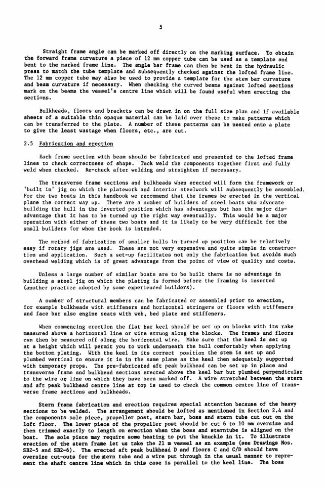
Straight frame angle can be marked off directly on the marking surface. To obtainthe forward frame curvature a piece of 12 mm copper tube can be used as a template andbent to the marked frame line. The angle bar frame can then be bent in the hydraulicpress to match the tube template and subsequently checked against the lofted frame line.The 12 mm copper tube may also be used to provide a template for the stem bar curvatureand beam curvature if necessary. When checking the curved beams against lofted sectionsmark on the beams the vessel's centre line which will be found useful when erecting thesections.
Bulkheads, floors and brackets can be drawn in on the full size plan and if availablesheets of a suitable thin opaque material can be laid over these to make patterns whichcan be transferred to the plate. A number of these patterns can be nested onto a plateto give the least wastage when floors, etc., are cut.
2 . 5 Fabrication and erection
Each frame section with beam should be fabricated and presented to the lofted framelines to check correctness of shape. Tack weld the components together first and fullyweld when checked. Re-check after welding and straighten if necessary.
The transverse frame sections and bulkheads when erected will form the framework or
'built in1
jig on which the platework and interior steelwork will subsequently be assembled.For the two boats in this handbook we recommend that the frames be erected in the vertical
plane the correct way up. There are a number of builders of steel boats who advocate
building the hull in the inverted position which has advantages but has the major dis-
advantage that it has to be turned up the right way eventually. This would be a major
operation with either of these two boats and it is likely to be very difficult for the
small builders for whom the book is intended.
The method of fabrication of smaller hulls in turned up position can be relatively
easy if rotary jigs are used. These are not very expensive and quite simple in construc-
tion and application. Such a set-up facilitates not only the fabrication but avoids much
overhead welding which is of great advantage from the point of view of quality and costs.
Unless a large number of similar boats are to be built there is no advantage in
building a steel jig on which the plating is formed before the framing is inserted
(another practice adopted by some experienced builders) .
A number of structural members can be fabricated or assembled prior to erection,for example bulkheads with stiffeners and horizontal stringers or floors with stiffenersand face bar also engine seats with web, bed plate and stiffeners.
When commencing erection the flat bar keel should be set up on blocks with its rake
measured above a horizontal line or wire strung along the blocks. The frames and floors
can then be measured off along the horizontal wire. Make sure that the keel is set upat a height which will permit you to work underneath the hull comfortably when applyingthe bottom plating. With the keel in its correct position the stem is set up and
plumbed vertical to ensure it is in the same plane as the keel then adequately supportedwith temporary props. The pre-fabricated aft peak bulkhead can be set up in place and
transverse frame and bulkhead sections erected above the keel bar but plumbed perpendicularto the wire or; line on which they have been marked off. A wire stretched between the stern
and aft peak bulkhead centre line at top is used to check the common centre line of trans-
verse frame sections and bulkheads.
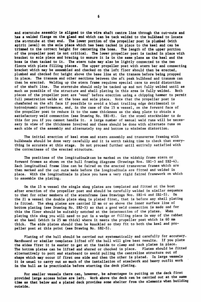
Stern frame fabrication and erection requires special attention because of the heavysections to be welded. The arrangement should be lofted as mentioned in Section 2.4 and
the components sole piece, propeller post, stern bar, boss and stern tube cut out on the
loft floor. The lower piece of the propeller post should be cut 6 to 10 mm oversize and
then trimmed exactly to length on erection when the boss and sterntube is aligned on the
boat. The sole piece may require some heating to put the knuckle in it. To illustrate
erection of the stern frame let us take the 21 m vessel as an example (see Drawings Nos.
SB2-5 and SB2-6) . The erected aft peak bulkhead D and floors C and C/D should have
oversize cut-outs for the stern tube and a wire put through in the usual manner to repre-
sent the shaft centre line which in this case is parallel to the keel line. The boss
and sterntube assembly is aligned to the wire shaft centre line through the cut-outs and
has a welded flange on the gland end which can be tack welded to the bulkhead to locate
the starntube at that end. The lower portion of the propeller post is plumbed (with
spirit level) on the sole piece which has been tacked in place to the keel and can betrimmed to the correct height for centering the boss. The length of the upper portionof the propeller post is not critical. The lower propeller post is tacked in place withbracket to sole piece and bracing to ensure it is in the same plane as the keel and the
boss is then tacked to it. The stern tube may also be lightly connected to the two
floors with plate filling pieces. The upper propeller post with stern bar and connectingbracket which may be assembled and checked on the loft floor should then be erected,
plumbed and checked for height above the base line at the transom before being proppedin place. The transom and other sections between the aft peak bulkhead and transom can
then be erected. Welding up the stern frame requires special care to avoid distortionof the shaft line. The sterntube should only be tacked up and not fully welded until as
much as possible of the structure and shell plating in this area is fully welded. Both
pieces of the propeller post are 'veed1
before erection using a chipping hammer to permitfull penetration welds at the boss and sole piece. Note that the propeller post is
chamfered on the aft face if possible to avoid a blunt trailing edge detrimental to
hydrodynamic performance, and, in the case of the 15 m vessel, on the forward face of
the propeller post to reduce it to the same thickness as the skeg plate to obtain a
satisfactory weld connection (see Drawing No. SB1-8). Get the steel stockholder to do
this for you if you cannot handle it. A large number of manual weld runs will be neces-
sary in view of the thickness involved and these should be done with alternate runs on
each side of the assembly and alternately top and bottom to minimise distortion.
The initial erection of keel stem and stern assembly and transverse framing with
bulkheads should be done very carefully and it is worth taking time to check that every-
thing is accurate at this stage. Do not proceed further until entirely satisfied with
the correctness of the erected structure.
The positions of the longitudinals can be marked on the midship frame stern or
forward frames as shown on the hull framing diagrams (Drawings Nos. SB1-3 and SB2-4).
Each longitudinal frame line can be faired on the erected transverse frames which are
then marked and the cut outs made before the longitudinals are fitted and welded in
place. With the longitudinals in place you have a very rigid faired framework on which
to assemble the plating.
On the 15 m vessel the single skeg plates are templated and fitted at the boat
after erection of the propeller post and should be carefully welded in similar sequence
to that for other members of the sternframe (see Drawings Nos. SB1-4 and SB1-5). On
the 21 m vessel the double plate skeg is plated first, that is before any shell platingis fitted. The skeg plates are carried 12 mm or so above the inner surface line of
bottom plating (see Drawing No. SB2-5) so that a good weld connection is made and for
this the floor should be suitably notched at the intersection of the plates. When
plating this skeg you will need to put in a wedge or filling piece in way of the rabbet
at the keel (which is 25 mm thick) where it meets the propeller post which is 60 mm
thick. The side plates should then be knuckled so they fit to both the keel and pro-
peller post at this point (see Drawing No. SB2-5).
Plating of the hull should be carried out systematically and carefully for accuracy.
Hardboard or similar templates lifted off the hull will give best results. If you plate
the sides first it is easier to get at the inside to clamp and tack plates in place.
The bottom plates can be lifted and shored or chocked in place. Plates should be fitted
alternatively to port and starboard to avoid pulling the centreline structure out of
shape which may occur if first one side and then the other is plated. In large vessels
it is usual to carry out as much of the installation of steelwork and heavy outfit work
in the hull as is practicable before starting the deck plating.
For smaller vessels there can, however, be advantages in putting on the deck first
provided large access holes are left. Work above the deck can be carried out at the same
time as that below and a plated deck provides some shelter from the elements when building
outside.
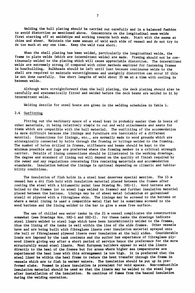
Welding the hull plating should be carried out carefully and in a balanced fashionto avoid distortion as mentioned above. Concentrate on the longitudinal seam weldsfirst starting off at amidships and working towards both ends. Start with the seams atchine and sheer. Maintain the same amount of weld each side of vessel and do not try todo too much at any one time. Keep the weld runs short.
When the shell plating has been welded, particularly the longitudinal welds, theframe to plate welds (which are intermittent welds) are made. Framing should not be con-tinuously welded to the plating which will cause appreciable distortion. The intermittentwelds are extremely strong if compared with other methods employed for fastening framesin boatbuilding. Bulkheads should be left until last because continuous welds to theshell are required to maintain watertightness and unsightly distortion can occur if thisis not done carefully. Use short lengths of weld about 35 mm at a time with cooling inbetween welds.
Although more straightforward than the hull plating, the deck plating should also be
carefully and systematically fitted and welded before the deck beams are welded to it byintermittent welds.
Welding details for steel boats are given in the welding schedules in Table 1.
2.6 Outfitting
Fitting out the machinery space of a steel boat is probably easier than in boats of
other materials, it being relatively simple to cut and weld attachments and seats for
items which are compatible with the hull material. The outfitting of the accommodationis more difficult because the linings and furniture are inevitably of a different
material. Connections for linings, etc., are normally made to wood grounds which are
strategically connected by bolts through the framing or bylings welded to the framing.The number of holes drilled in frames, stiffeners and beams should be kept to the
minimum possible and lugs are preferred where the framing member is a critical strengthcarrier. Details of lining connections should be illustrated in the working drawings.The degree and standard of lining out will depend on the quality of finish required bythe owner and any regulations concerning fire resisting materials and accommodation
standards. Insulation behind the linings is optional depending on climatic and habita-
bility conditions.
The insulation of fish holds in a steel boat deserves special mention. The 15 mvessel has a dry fish hold with insulation material placed between the frames after
coating the steel with a bitumastic paint (see Drawing No. SB1-1). Wood battens are
bolted to the frames (or to steel lugs welded to frames) and further insulation material
placed between the battens. Linings may be of sheet metal (aluminium or galvanisedsteel) or plywood with a fibreglass skin. The linings may be screwed to the battens or
where a metal lining is used a compatible metal flat bar is sometimes screwed to the
wood battens and the lining welded to the bar to give a seam free surface.
The use of chilled sea water tanks in the 21 m vessel complicates the construction
somewhat (see Drawings Nos. SB2-1 and SB2-2). For these tanks the drawings indicate
steel liners welded to steel lugs which have been intermittently welded to the frames,
thus the lining of the tanks is well within the line of the side frames. Other vessels
have and are being built with fibreglass liners over insulation material sprayed onto
the hull or fibreglassed plywood liners over insulation at the hull sides. Considerable
loads are imposed by the tank contents and the author has experience of fibreglass ply-wood liners giving way after a short period of service hence the preference for the more
structurally sound steel liners. Most European builders appear to weld the liners
directly to the heel of the frames but for areas where higher sea temperatures are
experienced the heat loss with this arrangement is too high. It is preferred that the
steel liner be within the heel frame to reduce the heat transfer through the frame in
vessels which are to fish in wanner waters. The insulation should be put up in pre-
formed slabs. Foamed in place insulation is prevalent for void spaces. Non-combustible
insulation material should be used so that the liners may be welded to the steel lugs
after installation of the insulation. Be cautious of fumes from the heated insulation
during the welding operation.
Installation of machinery particularly the main engine is beet left to engineers
experienced in this work and the builder nay wish to sub-contract this work. Mote onlythat the vertical main engine bed plates (longitudinal bearers) with heavy flat bars on
the top should be integrated with the hull structure and possibly welded to the bulkheads
at each end (See Drawing No. SB1-4).
Foundations of all machinery should be strong and stiff enough and be welded to the
hull structural members.
The mechanical steering system for the two boats shown in Drawing No. SB1/2-3 in-
corporates a wormgear speed reducer of standard type which can be readily purchased from
most machinery agents. A reduction ratio of between 10 to 1 and 15 to 1 is generallyused. The speed reducer should have an extra bearing on the output shaft. The standard
speed reducer wormgear has a right hand thread and if installed the wrong way round the
ship will turn in the opposite direction to the wheel.
Propeller shafts for steel craft are normally made of bronze or stainless steel with
bronze liners working in ferrobestos lubricated bushes (see Drawings Nos. SB1-9 and SB2-8).
They are usually tapered at both ends and keyed to match the propeller and the half
coupling.
If the main engine Is situated well forward an intermediate shaft of forging qualitymild steel should be mounted with half couplings or forged flanges to match the propellershaft and engine crankshaft flanges.
If a nozzle is being manufactured care should be taken to obtain a smooth shape and
the design clearance between the nozzle and propeller tips should be accurately maintained.
The pipe systems on a steel boat do not differ from those used on boats constructed
in other materials but It is easier to fix them as holders can be welded to stiffeners.
Welding holders directly to the shell, bulkheads, and decks should be avoided as far as
possible as this could Injure locally the strength of the main hull structure If not pro-
perly done. Deck equipment must be mounted in strengthened areas and for heavily loaded
machinery and rigging reinforcements under the deck should be allowed for in the hull
construction drawings.
Small items of deck equipment can be welded over beams or local reinforcing brackets,
angle or flat bars can be added under the deck.
The rules for electric wiring on small steel vessels are the same as for other boats.
Cables are fixed to cable trays welded to the structure. The cabling should avoid water
contact, not being sited low in the bilge and where possible kept below deck or otherwise
given full protection. Cables exposed to the weather should be led in pipes or inside
masts and where a penetration through the deck or any other watertight partition is
necessary an efficient gland is important.
3. PROTECTION AGAINST CORROSION
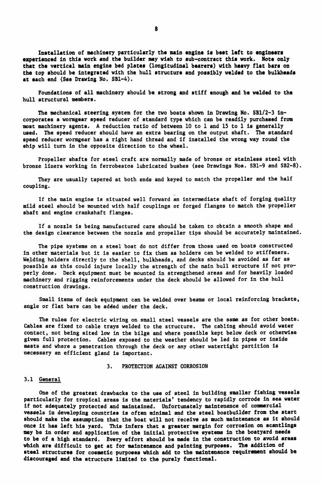
3.1 General
One of the greatest drawbacks to the use of steel in building smaller fishing vessels
particularly for tropical areas is the materials 1
tendency to rapidly corrode in sea water
if not adequately protected and maintained. Unfortunately maintenance of commercial
vessels in developing countries is often minimal and the steel boatbullder from the start
should make the assumption that the boat will not receive as much maintenance as it should
once it has left his yard. This infers that a greater margin for corrosion on scantlings
may be in order and application of the initial protective systems in the boatyard needs
to be of a high standard. Every effort should be made in the construction to avoid areas
which are difficult to get at for maintenance and painting purposes. The addition of
steel structures for cosmetic purposes which add to the maintenance requirement should be
discouraged and the structure limited to the purely functional.
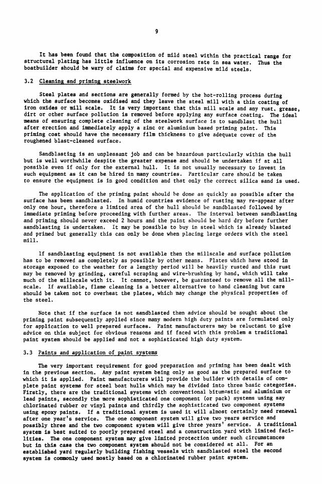
It has been found that the composition of mild steel within the practical range forstructural plating has little influence on its corrosion rate in sea water. Thus theboatbuilder should be wary of claims for special and expensive mild steels.
3.2 Cleaning and priming steelwork
Steel plates and sections are generally formed by the hot-rolling process duringwhich the surface becomes oxidised and they leave the steel mill with a thin coating ofiron oxides or mill scale. It is very important that this mill scale and any rust, grease,dirt or other surface pollution is removed before applying any surface coating. The idealmeans of ensuring complete cleaning of the steelwork surface is to sandblast the hullafter erection and immediately apply a zinc or aluminium based priming paint. This
priming coat should have the necessary film thickness to give adequate cover of the
roughened blast-cleaned surface.
Sandblasting is an unpleasant job and can be hazardous particularly within the hullbut is well worthwhile despite the greater expense and should be undertaken if at all
possible even if only for the external hull. It is not usually necessary to invest in
such equipment as it can be hired in many countries. Particular care should be takento ensure the equipment is in good condition and that only the correct silica sand is used.
The application of the priming paint should be done as quickly as possible after the
surface has been sandblasted. In humid countries evidence of rusting may re-appear after
only one hour, therefore a limited area of the hull should be sandblasted followed byimmediate priming before proceeding with further areas. The interval between sandblastingand priming should never exceed 2 hours and the paint should be hard dry before further
sandblasting is undertaken. It may be possible to buy in steel which is already blastedand primed but generally this can only be done when placing large orders with the steel
mill.
If sandblasting equipment is not available then the millscale and surface pollutionhas to be removed as completely as possible by other means. Plates which have stood in
storage exposed to the weather for a lengthy period will be heavily rusted and this rust
may be removed by grinding, careful scraping and wire-brushing by hand, which will take
much of the millscale with it. It cannot, however, be guaranteed to remove all the mill-
scale. If available, flame cleaning is a better alternative to hand cleaning but care
should be taken not to overheat the plates, which may change the physical properties of
the steel.
Note that if the surface is not sandblasted then advice should be sought about the
priming paint subsequently applied since many modern high duty paints are formulated onlyfor application to well prepared surfaces. Paint manufacturers may be reluctant to giveadvice on this subject for obvious reasons and if faced with this problem a traditional
paint system should be applied and not a sophisticated high duty system.
3.3 Paints and application of paint systems
The very important requirement for good preparation and priming has been dealt with
in the previous section. Any paint system being only as good as the prepared surface to
which it is applied. Paint manufacturers will provide the builder with details of com-
plete paint systems for steel boat hulls which may be divided into three basic categories.
Firstly, there are the traditional systems with conventional bitumastic and aluminium or
lead paints, secondly the more sophisticated one component (or pack) systems using say
chlorinated rubber or vinyl paints and thirdly the sophisticated two component systems
using epoxy paints. If a traditional system is used it will almost certainly need renewal
after one year's service. The one component system will give two years service and
possibly three and the two component system will give three years' service. A traditional
system is best suited to poorly prepared steel and a construction yard with limited faci-
lities. The one component system may give limited protection under such circumstances
but in this case the two component system should not be considered at all. For an
established yard regularly building fishing vessels with sandblasted steel the second
system is commonly used mostly based on a chlorinated rubber paint system.
10
Table 2 Indicates typical steal boat coating ayatema including deck and houae aawell aa the bull. It ia debatable aa to whether it ia naceaaary to apply anything morethan the cheap traditional paint ayatem to areaa other than the hull in fiahing vassals.
Anti-fouling painta which prevent marine growth on the underwater hull come indifferent strengths and formulations and if the veaael ia to operate in tropical or semi-
tropical conditions where fouling could be heavy, ensure that a super tropical or similar
antl-fouling paint is used. Longlife anti-fouling painta should be uaed with the highduty paint systems if the benefit of longer periods between drydockings is to be achieved.Follow the manufacturers recommendations as to the minimum and maximum times allowedbefore the newly applied anti-fouling coasting is Immersed.
Internal spaces below deck should also be painted carefully in accordance with paintmanufacturers recommendations. Particularly prone to corrosion are the bilges and steelareas behind fish hold linings and inside the skeg which should be treated with bltumastic
coatings. The insides of fresh water tanks should be coated with a substance which willnot taint the water. A cement wash is often applied. Fuel tanks should be left unpalntedinternally and covered by a thin layer of oil after cleaning.
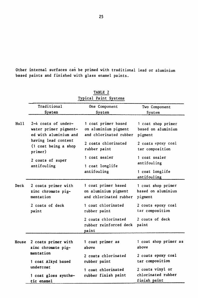
Other Internal surfaces can be primed with traditional lead or aluminium based paintsand finished with gloss enamel paints.
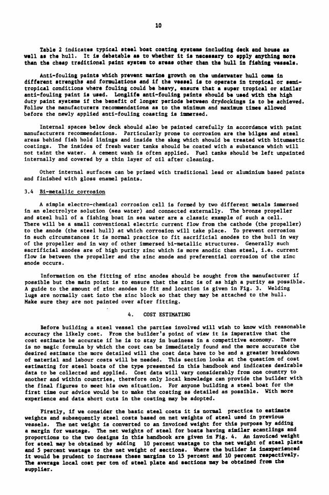
3.4 Bl-roetalllc corrosion
A simple electro-chemical corrosion cell is formed by two different metals immersedin an electrolyte solution (sea water) and connected externally. The bronze propellerand steel hull of a fishing boat in sea water are a classic example of such a cell.
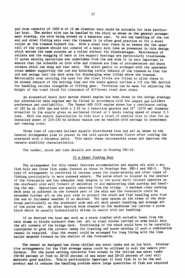
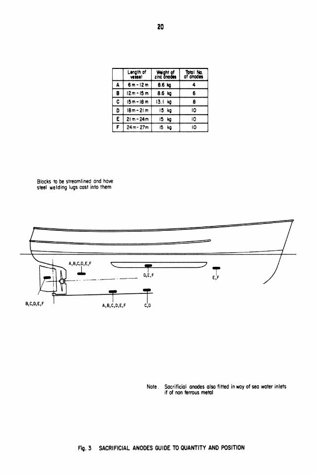
There will be a small conventional electric current flow from the cathode (the propeller)to the anode (the steel hull) at which corrosion will take place. To prevent corrosionIn such circumstances it Is normal practice to fit sacrificial anodes to the hull in wayof the propeller and in way of other immersed bi-metallic structures. Generally such
sacrificial anodes are of high purity zinc which is more anodic than steel, I.e. currentflow is between the propeller and the zinc anode and preferential corrosion of the zinc
anode occurs.
Information on the fitting of zinc anodes should be sought from the manufacturer if
possible but the main point is to ensure that the zinc Is of as high a purity as possible.A guide to the amount of zinc anodes to fit and location is given in Fig. 3. Welding
lugs are normally cast Into the zinc block so that they may be attached to the hull.
Make sure they are not painted over after fitting.
4. COST ESTIMATING
Before building a steel vessel the parties involved will wish to know with reasonable
accuracy the likely cost. From the builder's point of view It Is imperative that the
cost estimate be accurate if he is to stay in business In a competitive economy. There
is no magic formula by which the cost can be Immediately found and the more accurate the
desired estimate the more detailed will the cost data have to be and a greater breakdown
of material and labour costs will be needed. This section looks at the question of cost
estimating for steel boats of the type presented In this handbook and indicates desirable
data to be collected and applied. Cost data will vary considerably from one country to
another and within countries, therefore only local knowledge can provide the builder with
the final figures to meet his own situation. For anyone building a steel boat for the
first time our advice would be to make the costing as detailed as possible. With more
experience and data short cuts In the costing may be adopted.
Firstly, if we consider the basic steel costs it is normal practice to estimate
weights and subsequently steel costs based on net weights of steel used in previousvessels. The net weight is converted to an invoiced weight for this purpose by adding
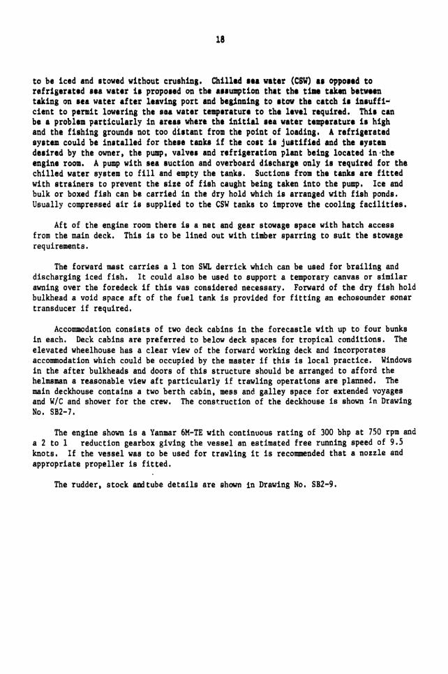
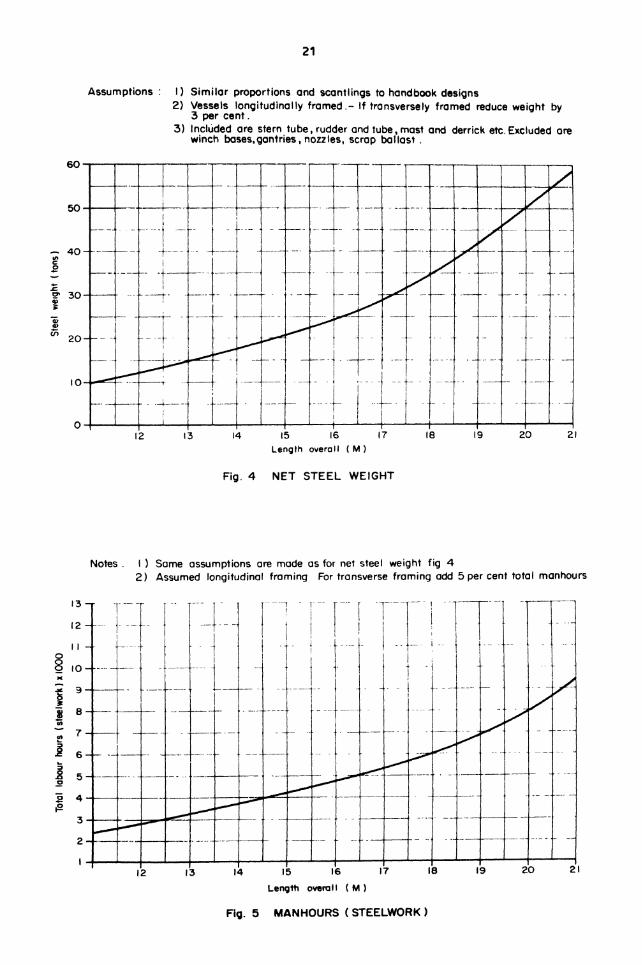
a margin for wastage. The net weights of steel for boats having similar scantlings and
proportions to the two designs in this handbook are given in Fig. 4. An invoiced weight
for steel may be obtained by adding 10 percent wastage to the net weight of steel plate
and 5 percent wastage to the net weight of sections. Where the builder ia inexperiencedit would be prudent to increase these margins to 15 percent and 10 percent respectively.
The average local coat per ton of steel plate and aectiona may be obtained from the
supplier.
11
For greater accuracy in estimating the steel costs the average cost per ton of plateand sections may be considered separately since there is often a significant difference(see Tables 3, 4, 5 and 6). Also a number of very heavy rolled sections may be considerablymore expensive than the rest and these can be added separately. These sections may, infact, be quoted on a cost per length basis rather than per ton.
Having obtained the total material cost for steel, the cost of welding consumables,cutting gases, etc., may be estimated as a percentage of this total. An average figurewould be 15 percent.
Labour costs for the steelwork and other work are determined from the recorded hoursworked on previous boats. Any efficient boatyard will keep detailed records of the hoursworked by different traders on various components of the boat. For comparative purposeswhen dealing with steelwork the total hours may be converted to a manhours per ton ofsteelwork ratio. The total hours worked by a small experienced steel boatyard in a
developed country constructing boats similar to those in this handbook are shown in
Fig. 5. The manhours recorded by inexperienced boat builders in countries where materialsand tools, etc., are not readily to hand and climatic conditions are difficult may proveto be 50 to 100 percent higher. For preliminary costings an average figure for manhours/ton for the total hull and house steelwork may be sufficient. For greater accuracy theboatbuilder may sub-divide the steelwork into components where there can be a markedvariation in manhours depending on the complexity of the work. Typical subgroupings are:
(1) Framing and Bulkheads
(2) Hull Plating(3) Deck and Hatches
(4) Deckhouses
(5) Bulwark and Belting(6) Tanks
(7) Mast, Boom and Gantry.
Manhours/ton on the last two items are much higher than on the other items.
Knowing the manhours required for the steelwork this may be converted to a labour
cost by multiplying the total manhours by an hourly wage rate. This average hourly wagerate is not usually that paid to a single tradesman employed on the boat but is in effect
what is sometimes referred to as a 'charge out1 rate for labour. That is the total wage
bill for the boatyard plus cost of ancillary benefits paid to employees and charges to
the yard resulting from employment of personnel plus all overheads determined for a
certain time period. This figure is reduced to an hourly rate and divided by the number
of persons actually employed in boat construction to give the manhour cost rate. This is
obviously somewhat higher than the take home hourly pay rate of the tradesman.
The steelwork which in weight and physical terms may constitute the greater part of
the finished boat may in cost terms be as little as 25 percent of the total. This item
is in effect the easiest to cost and the machinery and outfit which constitutes the bulk
of the cost can prove more difficult and give rise to greater errors. A large proportionof this will need to be costed individually.
The major 'bought in1 items should be costed by obtaining quotations from the manu-
facturers or his agent. The following would fall into this category:
(1) Main engine, shafting and propeller.
(2) Auxiliary machinery such as generators, pumps, power steering and
refrigerating plant.
(3) Winches.
(4) Fishing gear such as power blocks, net drums, special davits, etc.
(5) Electronic devices such as radios, fishfinders, etc.
Installation of these items is costed on the basis of a knowledge of the material
and labour costs involved in the installation of each item. Some of this installation
work may be sub-contracted and a quotation from the sub-contractor is necessary.
12
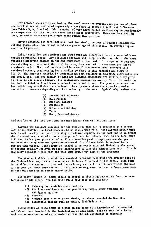
Tht remaining general outfit of the boat may be divided into two groupes hull outfitand machinery outfit. For a flrat eetimate of the hull and machinery outfit weights itla not uncommon for daalgnera to employ the to-called Cubic Number (CUNO) principle where*
by weighte are compared on a volumetric baaia for like hulls, The CUNO of a veaael is
the product of multiplication of the vessels overall length, beam and moulded depth.For example the 15 m vessel has a CUNO of 15 x 5 x 2,4 180 and the 21 m vessel a CUNOof 21 x6.5x3, 6* 491. To illustrate the method let us consider the hull outfit weightof the 15 m vessel which is 4.1 tons and use the CUNO ratio to estimate the hull outfit
weight of the 21 m vessel. Thus,
AO14.1 x
ygjj11.2 tons
Actually the hull outfit weight of the 21 m vessel is 12.3 tons but there is a non-
proportionately greater amount of fish hold insulation in the larger vessel which wouldhave to be taken into consideration.
It is proposed in a number of publications that the subsequent costings of hull and
machinery outfit be based on a cost per ton of outfit weight for labour and material.
While this is sufficient for a preliminary estimate, in practice, where greater accuracyis required, this is difficult because many of the items normally associated with hull
and machinery outfit have considerable variations in material costs and manhour rates.
For the hull outfit of a steel vessel, it Is suggested that this be sub-divided
into the four following categories for greater accuracy:
(1) Fish Hold Lining(2) Accommodation outfit and miscellaneous woodwork
(3) Hardware - windows, vents, handrails, ladders, etc.
(4) Sandblasting, painting and anodes.
Given the costs for a similar vessel of like proportions the fish hold lining costs,
both material and labour, may be compared in the ratio of the respective hold capacities,i.e. per cubic metre of fish hold. The accommodation outfit and hardward may be compared
using the CUNO method and since paint costs are generally established on a cost per
square metre basis, it is suggested that they be compared on a length squared (L^) basis.
In costing the labour any change in the hourly rate since building the previous vessel
should be taken into account. Adjustment on a percentage basis should also be made for
increases in material costs.
The machinery outfit can be sub-divided into the three following categories for
greater accuracy.
(1) Engine related systems(2) Pipe systems(3) Electrical.
The first item which includes exhaust, controls, sea connections, lub oil tank and piping,is probably best calculated directly by individual component. It is difficult to relate
it to engine size or cost and is independent of vessel size. As a preliminary estimate
it may be 15 to 25 percent of the engine cost, the higher figure being for the cheapermodel of engine. Pipe systems which include bilge, ballast and fire main, and generalservice systems, can be compared on a CUNO basis since they are a function of the size
of the boat. The electrical system should be costed for the boat either by quotation if
sub-contracted or by itemised material costs and manhour estimates if the boatyard is
undertaking the work* Expensive items like switchboards should be costed by obtaining
quotations.
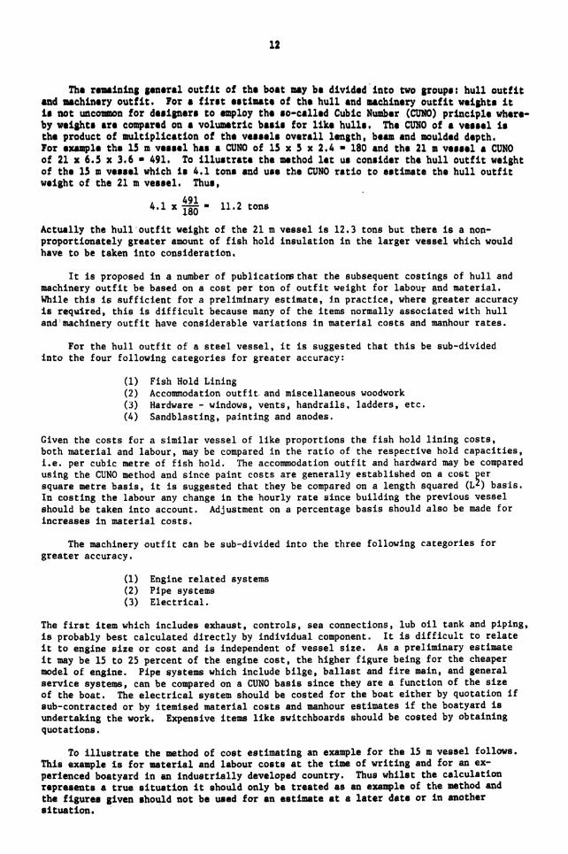
To illustrate the method of cost estimating an example for the 15 m vessel follows.
This example is for material and labour costs at the time of writing and for an ex-
perienced boatyard in an industrially developed country. Thus whilst the calculation
represents a true situation it should only be treated as an example of the method and
the figures given should not be used for an estimate at a later date or in another
situation.
13
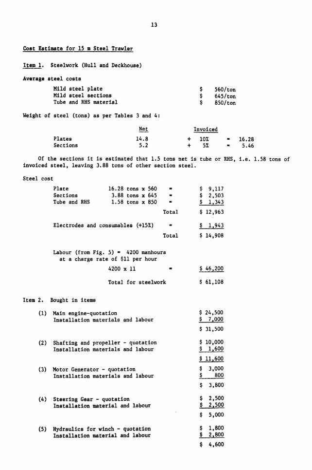
Coat Estimate for 15 m Steel Trawler
Item I. Steelwork (Hull and Deckhouse)
Average steel costs
Mild steel plate $ 560/tonMild steel sections $ 645/tonTube and RHS material $ 850/ton
Weight of steel (tons) as per Tables 3 and 4:
Net Invoiced
Plates 14.8 + 10% - 16.28Sections 5.2 -1-5% 5.46
Of the sections it is estimated that 1.5 tons net is tube or RHS, i.e. 1.58 tons of
invoiced steel, leaving 3.88 tons of other section steel.
Steel cost
Plate 16.28 tons x 560 $ 9,117Sections 3.88 tons x 645 $ 2,503Tube and RHS 1.58 tons x 850 * $ 1,343
Total $ 12,963
Electrodes and consumables (+15%) c$ 1,943
Total $ 14,908
Labour (from Fig. 5) * 4200 manhours
at a charge rate of $11 per hour
4200 x 11 - $ 46,200
Total for steelwork $ 61,108
Item 2. Bought in items
(1) Main engine-quotation $ 24,500
Installation materials and labour $ 7,000
$ 31,500
(2) Shafting and propeller- quotation $ 10,000
Installation materials and labour $ 1,600
$ 11.600
(3) Motor Generator - quotation $ 3,000
Installation materials and labour $ 800
$ 3,800
(4) Steering Gear - quotation $ 2,500
Installation material and labour $ 2.500
$ 5,000
(5) Hydraulics for winch - quotation $ 1,800
Installation material and labour $ 2.800
$ 4,600
14
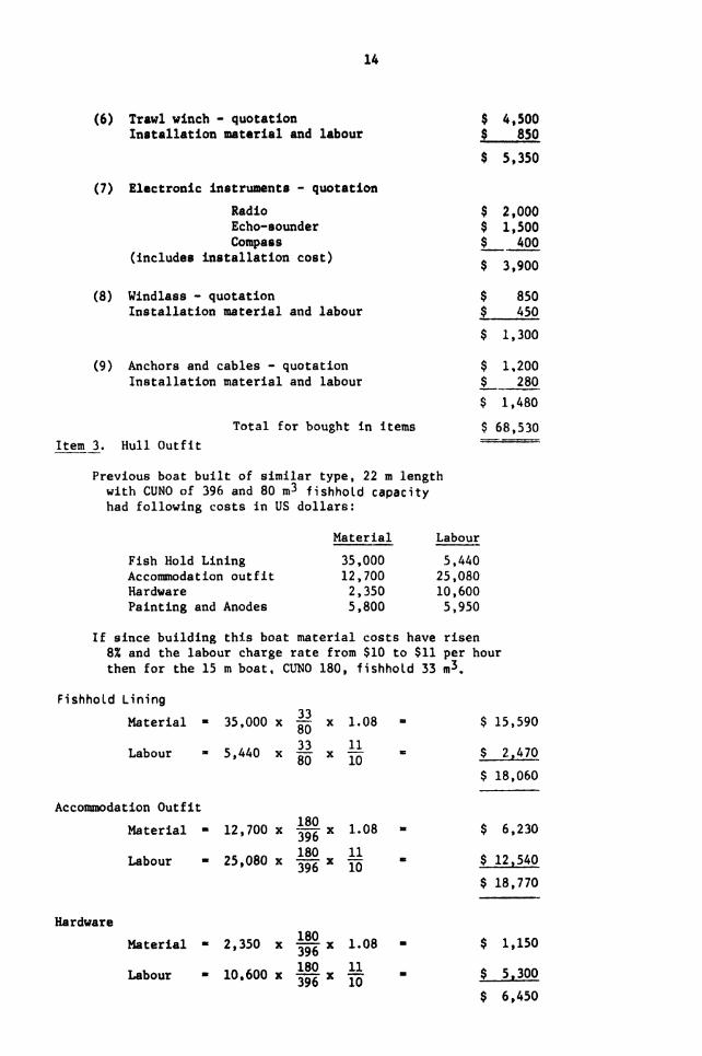
(6) Trawl winch - quotation $ 4,500Installation material and labour $ 850
$ 5,350
(7) Electronic instruments - quotation
Radio $ 2,000Echo-sounder $ 1 , 500
Compass $ 400
(includes installation cost) e
(8) Windlass - quotation $ 850Installation material and labour $ 450
$ 1,300
(9) Anchors and cables - quotationInstallation material and labour
Total for bought in items
Item 3. Hull Outfit
Previous boat built of similar type, 22 m lengthwith CUNO of 396 and 80 m3 fishhold capacityhad following costs in US dollars:
Material Labour
Fish Hold Lining 35,000 5,440Accommodation outfit 12,700 25,080Hardware 2,350 10,600
Painting and Anodes 5,800 5,950
If since building this boat material costs have risen
8% and the labour charge rate from $10 to $11 per hour
then for the 15 m boat, CUNO 180, fishhold 33 m3 .
Fishhold Lining
Material - 35,000 x||
x 1.08 $ 15,590
Labour - 5,440 x|~
x-j~
$ 2,470
$ 18,060
Accommodation Outfit180
Material - 12,700 x ~x 1.08 $ 6,230
Labour - 25,080 x x ~~ - $ 12,540
$ 18,770
Hardware
Material - 2,350 x -r x 1.08 - $ 1,150
Labour - 10,600 xjr
x ~ - $ 5.30010
$ 6,450
15
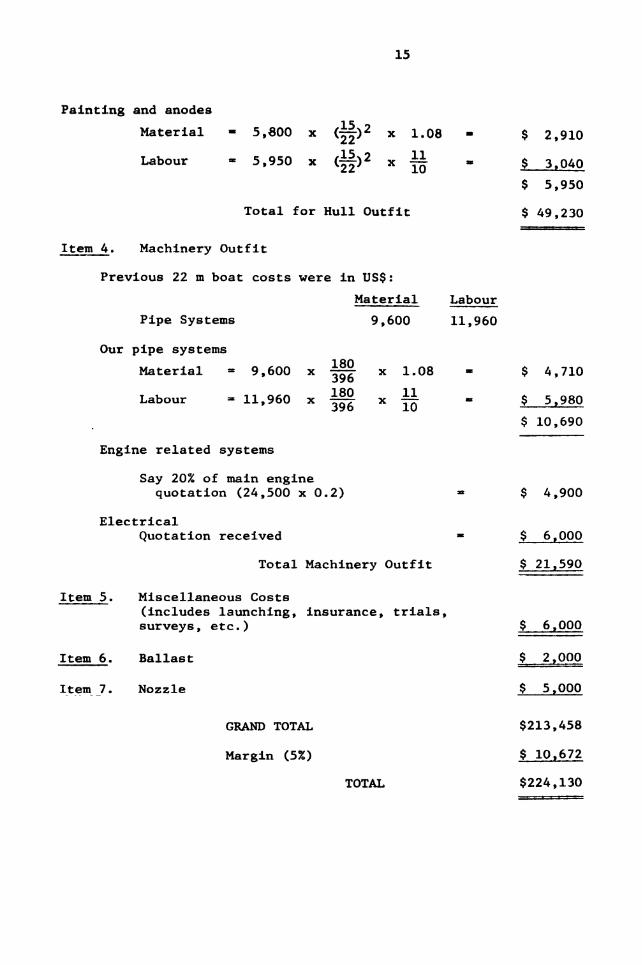
Painting and anodes
Material - 5,800 x(||)
2 x 1.08 - $ 2,910
Labour - 5,950 x(||)
2 x ~j- $ 3,040
Total for Hull Outfit
Item 4 Machinery Outfit
Previous 22 m boat costs were in US$:
Material Labour
Pipe Systems 9,600 11,960
Our pipe systems
Material 9,600 x ~~r x 1.08 - $ 4,710
Labour - 11,960 x - x ~~$ 5,980
$ 10,690
Engine related systems
Say 20% of main enginequotation (24,500 x 0.2) - $ 4,900
ElectricalQuotation received - $ 6,000
Total Machinery Outfit $ 21,590
Item 5. Miscellaneous Costs(includes launching, insurance, trials,surveys, etc.) $ 6,000
Item 6. Ballast $ 2,000
Item_7. Nozzle $ 5,000
GRAND TOTAL
Margin (5%)
TOTAL
16
ANNEX
OUTLINE SPECIFICATION FOR
15 m AND 21 m STEEL FISHING BOATS
The two designs illustrated in this handbook represent two quite different arrange-ments but having hulls which could be utilised with alternative layouts to suit a parti-cular fishery. Basically both boats could be considered multi-purpose although the
arrangements shown illustrate deck equipment for one particular type of fishing,
15 m Steel Fishing Boat
The design as presented in Drawing No. SB1-1 is purely for stern trawling and such a
design may be utilised for one boat bottom trawling in coastal waters and both bottom and
mid-water pair trawling. Where the fishing may be seasonal limiting the bottom trawlingto a part of the year then it is useful if the vessel can be utilised without major modi-fication to practice other forms of fishing. In this case using the basic hull designthe deck equipment could be re-arranged to allow the vessel to be operated as a combina-
tion trawler/purse seiner or as a long liner/gill netter. Utilised solely as a trawler
the stern gantry arrangement is preferred to carry the trawl blocks with a direct warplead from winch and tackle for lifting the cod end over the transom. If the vessel were
to be used as a combination trawler/purse seiner, the deck layout should be rearranged to
provide a mast and boom for handling both the trawl cod end and the purse seine. Portable
trawl davits should also be included so that the davit can be removed from the side on
which the purse seine net is to be hauled. The offset wheelhouse is so placed to provideadditional working space on the starboard side for either handling the purse seine or
for siting a net/line hauler for line and gill net fishing. The hauler should be posi-tioned forward where the helmsman can see the line or net coming aboard and there needs
to be adequate room to work around the hauler. For purse seining the purse davit could
be arranged on the starboard side with pursing wire leads from the athwartships winch
drums to lead blocks at the rear of the house hence to the purse davit. (See FAO Fisheries
Technical Paper No. 188, Fishing Boat Designs:3 - Small Trawlers). The house can be
arranged on the centreline if the vessel is intended only for stern trawling or offset
to starboard if the owner favours fishing from the port side.
The vessel has a large working deck area aft with raised forward deck for protection.An insulated fish hold for stowage of fish on ice is provided. With the insulated hold
aft in this type of boat and to utilise fully the space, it will tend to have restricted
depth aft and therefore two hatches are fitted to make loading and discharging easier
and reduce wastage in warmer climates. Typical fish hatch construction is shown in
Drawing No, SB1/2-4. The hold can usefully be subdivided for carrying ice to the groundsand smaller quantities of fish species if so desired. The hold in any case should be
fitted with removable and semi-permanent fish hold divisions about 1.5 m apart. Access
for inspection and re-packing of the stern gland is provided by a small section of port-able insulation at the bottom of the fish hold in way of the shaft. It is preferredthat lubrication of the bearing is done remotely from the engine room aft bulkhead area.
Accommodation consists of a wheelhouse with cooking and food storage/preparationfacilities adequate for some three to four days at sea. A separate toilet/shower with
entrance from the open deck is provided and there is below deck sleeping accommodation
with four berths. A sliding door, shown on Drawing No. SB1-11, on the helmsman's side
of the wheelhouse, does not interfere with the deck area and permits him to view any
fishing operation on the deck in the vicinity of the wheelhouse. A good view of the
winch and after working deck area which is a prerequisite of stern trawling operationsis also afforded the helmsman by the wheelhouse location and windows at the back of the
wheelhouse. The deckhouse construction is shown in Drawing No, SB1-7,
Deck gear consists of a two drum trawl winch with linked spooling equipment neces-
sary for the direct warp lead to the stern gantry. The winch may be hydraulicallydriven with pump driven from the power take off on the main engine (or auxiliary engine)
or can be mechanically driven with chain or belt drive from a pulley on the main engine
power take off to a layshaft arrangement. A winch with a pull of 1 1/2 tons at mid drum
17
and drum capacity of 1000 m of 12 mm diameter warp would be suitable for this particu-lar boat. The anchor wire can be handled by the winch as shown on the general arrange-ment drawing, the wire being stowed on a separate reel. To aid the handling of the codend and other fishing nets over the transom it is often good practice to fit a steelroller at the transom bulwark top. With a steel boat there is no reason why the upperrail of the transom should not consist of a heavy duty tube as presented in this designwhich serves the same purpose as a roller without its disadvantages. Maintenance ofrollers and the snagging of nets at its support bearings are particularly troublesome.If purse seining operations are undertaken from the one side it is very important toensure that the bulwarks on this side and transom are free of protuberances and sharpcorners which can snag and tear nets. The stern gantry is arranged with the uppermostcross member supporting the cod end hoisting tackle inboard of the transom so that thecod end swings into the deck area for discharging when lifted above the transom.Retractable arms carrying the eyes for the trawl blocks are fitted to allow these to
be stowed inboard of the belting line and the stern gantry carries a 1/2 ton SWL derrickfor handling catches alongside or lifting gear. Provision can be made for adjusting the
height of the trawl block for clearance of different trawl door sizes.
An economical heavy duty marine diesel engine has been shown in the design drawingsbut alternative main engines may be fitted in accordance with the owners and builders
preference and availability. The Yanmar 6KD CGC.'E engine shown has a continuous ratingof 165 hp at 1450 rpm and with a 3.55 to 1 reduction gearbox and 42" (1070 mm) diameter
propeller in the nozzle gives an estimated thrust at 4 knots towing speed of almost 2.5
tons. With the nozzle installation in this boat a trawl of similar size to that for an
installed power of 210-230 hp without nozzle can be handled with savings in investment
and running costs.
Three tons of concrete ballast equally distributed fore and aft as shown in the
General Arrangement plan is poured in the void spaces between floors after coating the
steelwork with a bitumous paint. This seals these inaccessible areas and improves the
vessels stability characteristics.
The rudder, stock and tube details are shown in Drawing SB1-10.
21 m Steel Fishing Boat
The arrangement for this vessel features accommodation and engine aft with a dryfish hold and three fish tanks forward as shown in Drawings Nos. SB2-1 and SB2-2. This
type of arrangement is preferred in various areas for purse-seining and other types of
fishing particularly in more exposed waters. The purse winch is located in the shelter
of the forecastle and has adequate lead lengths to the purse davit located opposite on
the starboard side well forward of amidships to aid maneuvering when pursing and handl-
ing the net. Operations are easily observed from the bridge. A maximum clear workingdeck area is achieved in the forward part of the ship and the forecastle could be
extended further aft on the port side to protect the winch and fish handling area from
the sun or inclement weather if so desired. The open spaces at the sides of the deck-
house particularly on the starboard side and aft deck permit handling and stowage aft
of the purse net. An after derrick boom stepped on the deckhouse top carries a purse
block which is usually hydraulically driven to assist with net handling.
If so desired the boat may work as a stern trawler with suitable leads from the
warp drums to blocks outboard then led aft to trawl blocks carried on arms built into
the aft corners of the bridge deck. Positioning of the winch would have to be carefully
considered to give the correct leads for trawling and purse seining if such a combination
vessel is required. Also the vessel could be arranged for long lining with the line
hauler mounted forward in the shelter of the forecastle.
The vessel as designed has three chilled sea water tanks and an ice hold. Alterna-
tive arrangements for the fish stowage space could be utilised to suit the owners pre-ference. For the purse seining operation fish stowed in the chilled sea water tanks
(50-60 percent of fish to 20-25 percent of sea water and 20-25 percent of ice) will
maintain good quality. This is particularly important if food fish is to be the end
product and it reduces the handling problem where large quantities of fish are required
18
to be iced and stowed without crushing. Chilled sea water (CSW) as opposed to
refrigerated sea water is proposed on the assumption that the time taken between
taking on sea water after leaving port and beginning to stow the catch is insuffi-
cient to permit lowering the sea water temperature to the level required. This can
be a problem particularly in areas where the initial sea water temperature is highand the fishing grounds not too distant from the point of loading. A refrigerated
system could be installed for these tanks if the cost is justified and the systemdesired by the owner, the pump, valves and refrigeration plant being located in 'the
engine room. A pump with sea suction and overboard discharge only is required for the
chilled water system to fill and empty the tanks. Suctions from the tanks are fitted
with strainers to prevent the size of fish caught being taken into the pump. Ice and
bulk or boxed fish can be carried in the dry hold which is arranged with fish ponds.
Usually compressed air is supplied to the CSW tanks to improve the cooling facilities.
Aft of the engine room there is a net and gear stowage space with hatch access
from the main deck. This is to be lined out with timber sparring to suit the stowage
requirements.
The forward mast carries a 1 ton SWL derrick which can be used for brailing and
discharging iced fish. It could also be used to support a temporary canvas or similar
awning over the foredeck if this was considered necessary. Forward of the dry fish hold
bulkhead a void space aft of the fuel tank is provided for fitting an echosounder sonar
transducer if required.
Accommodation consists of two deck cabins in the forecastle with up to four bunks
in each. Deck cabins are preferred to below deck spaces for tropical conditions. The
elevated wheelhouse has a clear view of the forward working deck and incorporatesaccommodation which could be occupied by the master if this is local practice. Windows
in the after bulkheads and doors of this structure should be arranged to afford the
helmsman a reasonable view aft particularly if trawling operations are planned. The
main deckhouse contains a two berth cabin, mess and galley space for extended voyagesand W/C and shower for the crew. The construction of the deckhouse is shown in Drawing
No. SB2-7.
The engine shown is a Yanmar 6M-TE with continuous rating of 300 bhp at 750 rpra and
a 2 to 1 reduction gearbox giving the vessel an estimated free running speed of 9.5
knots. If the vessel was to be used for trawling it is recommended that a nozzle and
appropriate propeller is fitted.
The rudder, stock and tube details are shown In Drawing No. SB2-9.

19
Heavy steel pins
approx. 75mm dio"
Heavy steel plates ?bmmat bench height with different
holes to adjust pins
Hydraulic valve two direction
with centre detent and spring
Hydraulic ram25 tonne
Fig. I BENDING PRESS FOR COLD BENDING FRAMES .STEM BARS ETC.
To raise perpendicular to horizontal base line
Top of rail
Deck
Chine
Offsetabove base
B,
Fig. 2 LOFTING DETAILS
20
Blocks to be streamlined and have
steel welding lugs cast into them
B,C,D,E,F A,B,C,D,E,F C,D
Note . Sacrificial anodes also fitted in way of sea water inlets
if of non ferrous metal
Rg, 3 SACRIFICIAL ANODES GUIDE TO QUANTITY AND POSITION
21
Assumptions : !) Similar proportions and scantlings to handbook designs2) Vessels longitudinally framed.- If transversely framed reduce weight by
3 per cent .
3) Included are stern tube, rudder and tube, mast and derrick etc. Excluded arewinch bases, gantries, nozzles, scrap ballast .
I2 13 14 15 16 17
Length overall ( M )
18 20 21
Fig. 4 NET STEEL WEIGHT
Notes . I ) Same assumptions are made as for net steel weight fig 42) Assumed longitudinal framing For transverse framing add 5 per cent total manhours
12 13 14 15 16 17
Length overall (M)
18 19 20 21
Fig. 5 MANHOURS ( STEELWORK )
22
23
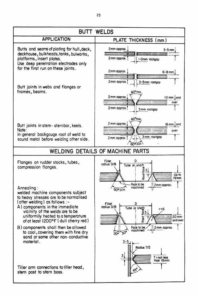
BUTT WELDSAPPLICATION PLATE THICKNESS (mm)
Butts and seams of plating for hull, deck,
deckhouse, bulkheads, tanks, bulwarks,
platforms, insert plates.
Usedeep penetration electrodes only
for the first run on these joints.
Butt joints in webs and flanges or
frames, beams.
2mmapprox. 3"5mrn
2mm appra.1 jT H3im rootgap I
~nr
6-8 mm[
2mmopprox. I
2mm approx.I
I I 3-5mm rootgop|
2 mm approx. j \T_/ IQmmjondrr^r^:~ "^^r^rr OV6r
Butt joints in stem- sternbar, keels.
Note :
in general backgouge root of weld to
sound metal before welding other side.
2mmapprolf Hi 3mmHr1--
60min
2mmapprox.^ \
rootgap
16 mm|and
WELDING DETAILS OF MACHINE PARTS
Flanges on rudder stocks, tubes,
compression flanges.
Annealing :
welded machine components subject
to heavy stresses are to be normalised
(after welding) as follows :-
A) components in the immediate
vicinity of the welds are to be
uniformity heated to a temperatureof at least I200F ( dull cherry red )
B) components shall then be a I lowed
to cool , covering them with fine drysand or some other non- conductive
material.
Tiller arm connections to tiller head,stern post to stern boss.
Fillet
radius D/8 Tube or, shaft
88,13LB-r-yy- ~
.
Up to
19mm
60min.
free to bemachined
* ip-
1 1 2mm approx.]Hh ~'
II
Fillet i DradiusD/Q r Tubeorsha;
V
Face to be/ 2mm approx.
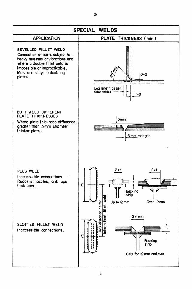
SPECIAL WELDSAPPLICATION PLATE THICKNESS (mm)
BEVELLED FILLET WELDConnection of parts subject to
heavy stresses or vibrations and
where a double fillet weld is
impossible or impracticable ,
Mast and stays to doubling
plates .
10-2
Leg length as perfillet tables
1-3
BUTT WELD DIFFERENTPLATE THICKNESSES
Where plate thickness difference
greater than 3mm chamferthicker plate.
3mm
3mm root gap
PLUG WELD
Inaccessible connections.
Rudders , nozzles , tank tops,tank liners .
2xt
in_]..
SLOTTED FILLET WELDInaccessible connections.
Only for 12 mm and over
25
Other internal surfaces can be primed with traditional lead or aluminium
based paints and finished with glass enamel paints.
TABLE 2
Typical Paint Systems
Traditional
System
One Component
System
Two Component
System
Hull 2-4 coats of under-
water primer pigment-
ed with aluminium and
having lead content
(1 coat being a shop
primer)
2 coats of super
antifouling
1 coat primer based
on aluminium pigment
and chlorinated rubber
2 coats chlorinated
rubber paint
1 coat sealer
1 coat longlife
antifouling
1 coat shop primerbased on aluminium
pigment
2 coats epoxy coal
tar composition
1 coat sealer
antifouling
1 coat longlife
antifouling
Deck 2 coats primer with
zinc chromate pig-
mentation
2 coats of deck
paint
1 coat primer based
on aluminium pigment
and chlorinated rubber
1 coat chlorinated
rubber paint
2 coats chlorinated
rubber reinforced deck
paint
1 coat shop primer
based on aluminium
pigment
2 coats epoxy coal
tar composition
2 coats of deck
paint
House 2 coats primer with
zinc chromate pig-
mentation
1 coat Alkyd based
undercoat
1 coat gloss synthe-
tic enamel
1 coat primer as
above
2 coats chlorinated
rubber paint
1 coat chlorinated
rubber finish paint
1 coat shop primer as
above
2 coats epoxy coal
tar composition
2 coats vinyl or
chlorinated rubber
finish paint
26
TABLE 3
STEEL QUANTITIES FOR 15m VESSEL
Mild Steel Plates (To B.S. 4360 ASTM-A131-74 or Equivalent)
12 "(D/E-I)
13 Deck Inserts
14 Nozzle Cylindrical Plate
15 Tanksides (G-I)16 "
(T-B)
17 Tanktop (D/E-G)18 Tanktop (G-I)
19 Manhole Plates20 Tank Ends (I) and Baffles
(G-H) and (H-I)
21 Bulkhead Plating above Floors22 Inspection Plate over Tunnel23 Bottom Plating24 Nozzle Conical Plate + Stiffs.
25 Deck Plating26 Side Plating and Fwd Bulkheads27 Transom Plating28 Hatch Coamings29 Hatch Covers30 Nozzle Throat Plate31 Bulwark Plating
Total
8 4.0
8
8
6
6
6
6
6
6
6
6
6
6
5
5
5
5
5
5
4
256.0
centre
1350 mm Outboard of
centre
) 1350 m Outboard of
) Centre. Net Figure) includes Cutouts for
) Manholes
Freeing Ports Included
Note Plate Material Listed is Nett QuantityAdd 10% Waste Allowance
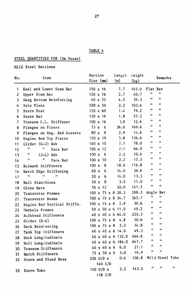
27
TABLE 4
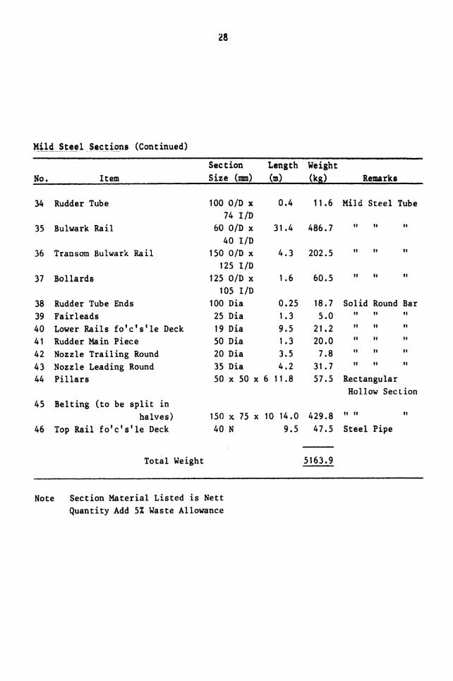
28
Mild Steel Sections (Continued)
Note Section Material Listed is Nett
Quantity Add 5% Waste Allowance
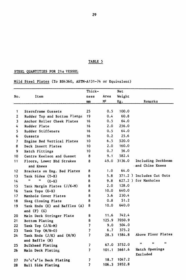
29
TABLE 5
STEEL QUANTITIES FOR 21m VESSEL
Mild Steel Plates (To BS4360, ASTM-A131-74 or Equivalent)
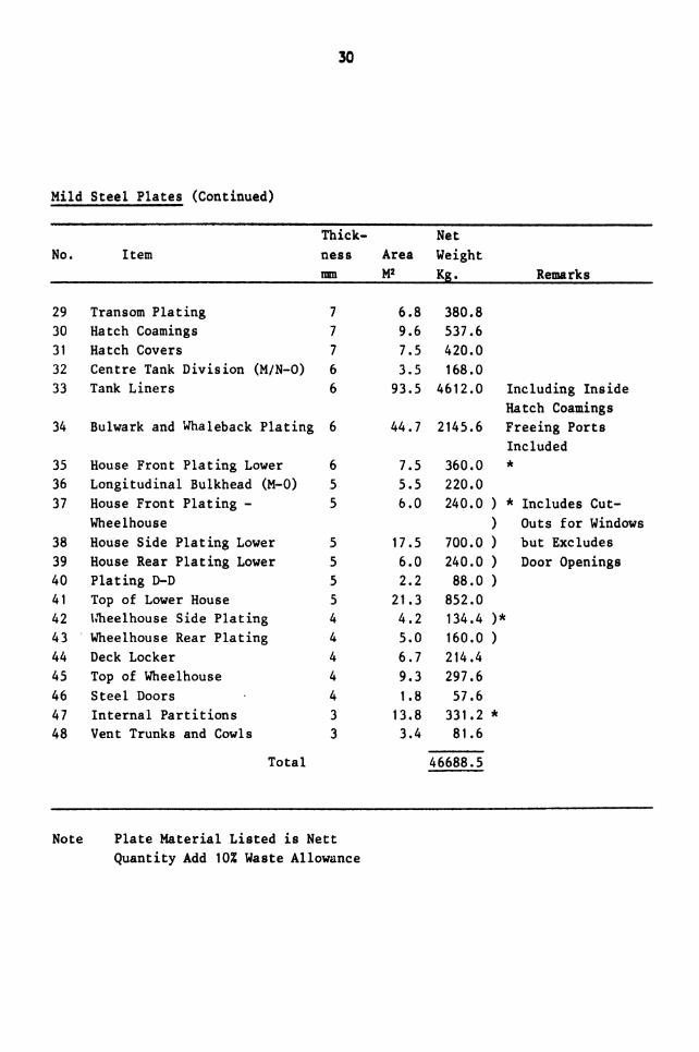
30
Mild Steel Plates (Continued)
Note Plate Material Listed is Nett
Quantity Add 10% Waste Allowance
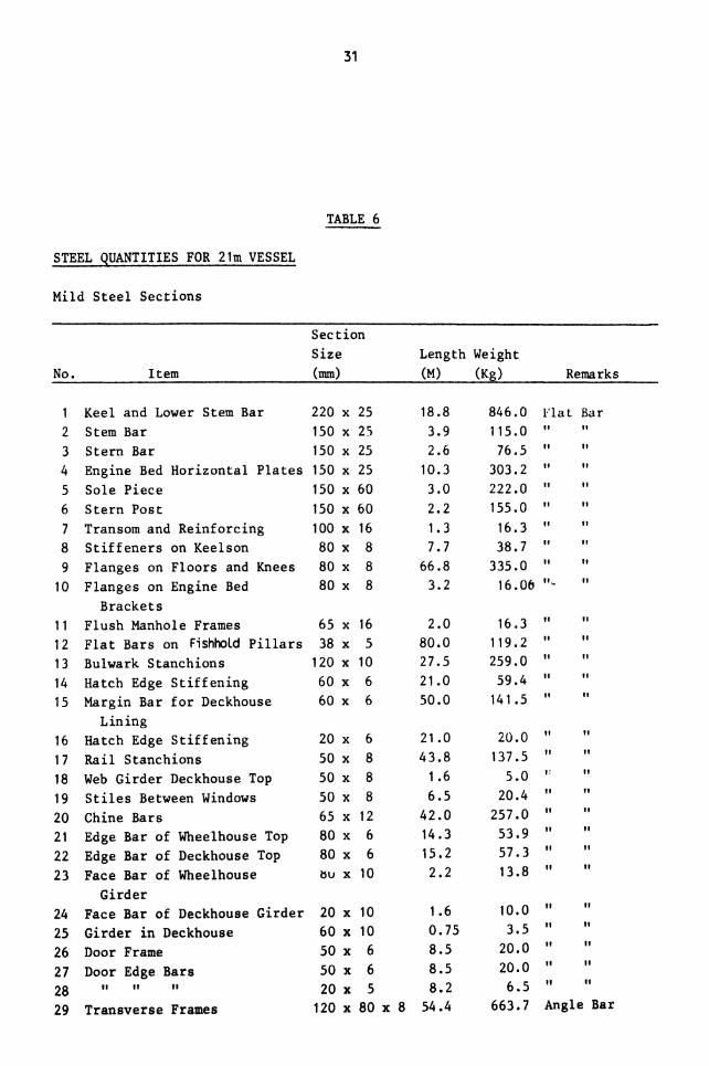
31
TABLE 6
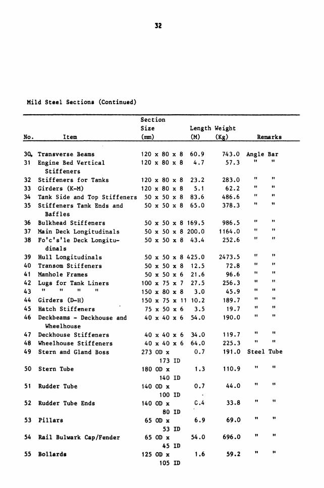
32
Mild Steel Sections (Continued)
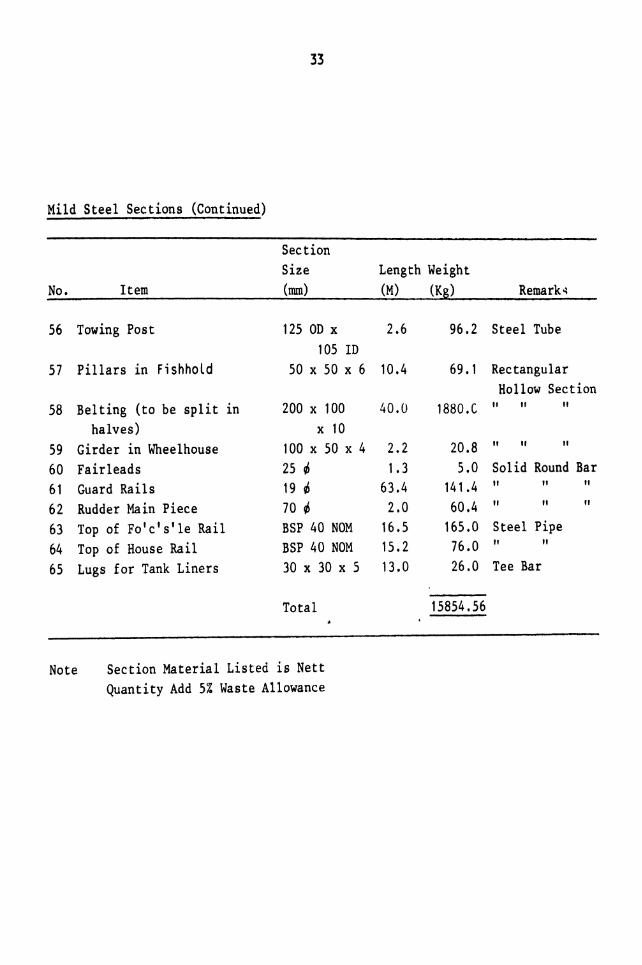
33
Mild Steel Sections (Continued)
Note Section Material Listed is Nett
Quantity Add 5% Waste Allowance

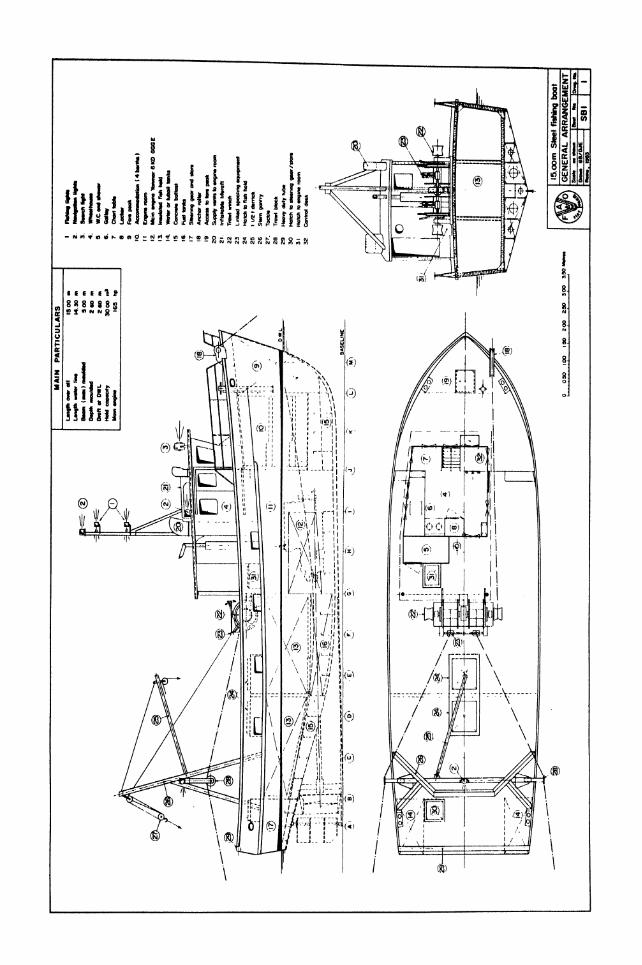
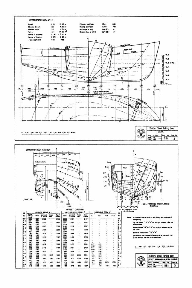
HYDROSTATIC DATA AT:-/.
_ f WLSIOW.L)
Priimotk cMfllofent
MWtlp ootffMtnt
Holf onglf of tnty
Buttock trow 011/4 B
090 100 150 200 290 300 390 400 490 900 Ifctnt
I5oom Steel fishing boot
LINES
STANDARD DECK-CAMBER
BASELINE
2800.
OFFSET DIAGRAMHEIGHTS ABOVE BL
1709
1590
I46T
1340
1840
1143
10*8
1012
1031
1098
1160l?4
13464449
I9601679
1790
1929
?0322139
2716
2683
2653
2639
2632
2648
2678
2756
2820
29??
3040
3170
3286
3242
3360
3490
3606
3460
3418
3364
3353
3339
3346
3378
3436
3B20
3622
3740
HALF BREADTHS FROM t
WOO20302071
210621402tas2219
224222672261
22942301
23032294227227402186?I021962
1626
1639
1420
'
2152*
2292
2332
2419
2207
2267
2374
2466
2496
2499
2423
2443
2493
2499
2461 - 2490
2416 - 2430
2235 2290 ?M9
1871 2010 2163
1300 1490 1702
646 696 106?
FROM I
om
107710601034100396?
874843792
373207013789MO3?9
1026 1243
425 996
HULL FRAMING AND PLATINGDIAGRAM
Notw All of(Mtt In mm to to*l* of hull pto()ng and undtnWc of
dk plating
Top KJt fromti "TR"to Van straight bttwwn cMrw and
dMfc/knuckki
Bottom framH "TR"to"F G"ait itraiglit MwMn profit*
ondchln*
Bulworta tlroioM <rom "TRHto"K"
Holf bnwdth and diagonal oflwti are to to mtotumd from
f and not (ram Int tkto of tht kMl /Htm
050 100 IX> 200 290 300 350 Mi
15.00m Steel fishing boot
OFFSETS .FRAMING a PLATING D
SBI
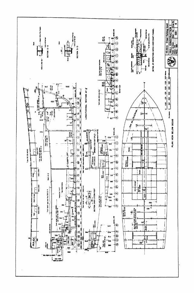
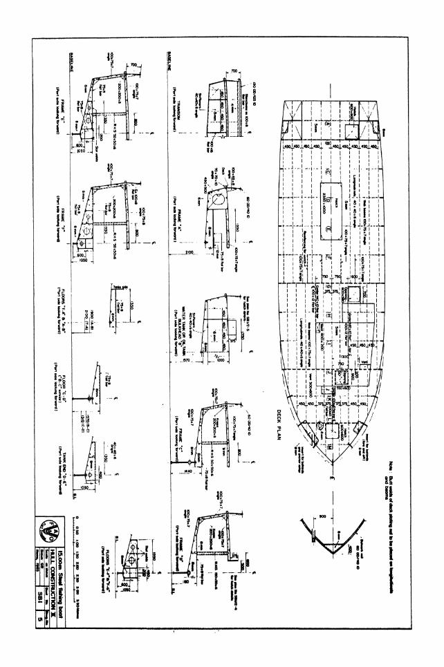
5.
8SS..
a
*i
ri
is I'-
ll-
..J*o
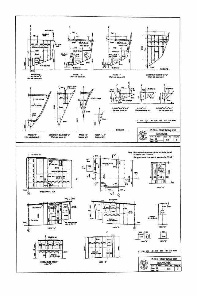
WATERTIGHTBULKHEAD "G"
(Port ndi tookmq oil!
FLOORS"0-H"a"H-l" FLOORVj" FLOOf6"j-K'a"K-L"
( Port tkfclwkmg oft) ( Port iid looking all ) J Port tkto looking ofl )
050 100 ISO 200 290 300 SUMttrn
15.00m Steel fishing boot
Scoli oiitexn[5oat
No Dmg No
SBI 6
Note Butt welds of deckhouse plating not to be placed
on beams and sliffeners .
Fix typical deckhouse details see plan No SBI/2-1
1 5.00m Steel fishing boot
WHEELHOUSE FRONT
VIEW "C"
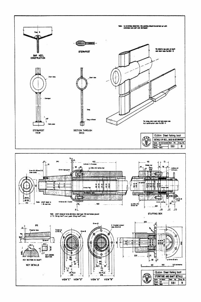
BAR KEELCONSTRUCTION
,r
STERNPOSTVIEW
STERNPOST
SECTION THROUGHSKEG
,..
hullconitructlonplonN.SBl-4
I5.oom Steel fishing boat
DETAILS OF KEEL, SKEG ft STERNPOST
Scolt not tot* tooted !
SB I
Nota thoft mottrtot tote Halntou UMl IM 316 cwitwttu groundUTS &6kg/fflm>(min)yttkt 2eng/mm*{mln)
VIEW"C" VIEW"D" VIEW "A" VIEW'S"
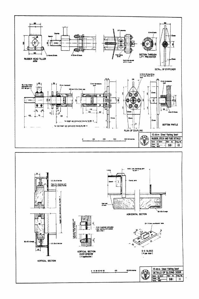
Fix tonjthMt conKruclwn drawing N.SBI -4_^
Fa lowl Itngth w conduction drawing N* SBI -4
*J
Chick ftx cttaranct with
HORIZONTAL SECTION
I-SS5flolb*
VERTICAL SECTION
OVER WINDOW
(ifapplicabl*)
VERTICAL SECTION
1020304090 10015 oom Steel fishing boot
DETAILS OF SLIDING DOOR
SoH 01 Dm* 1
'
Bo N Ck9 H
&~? SBI II
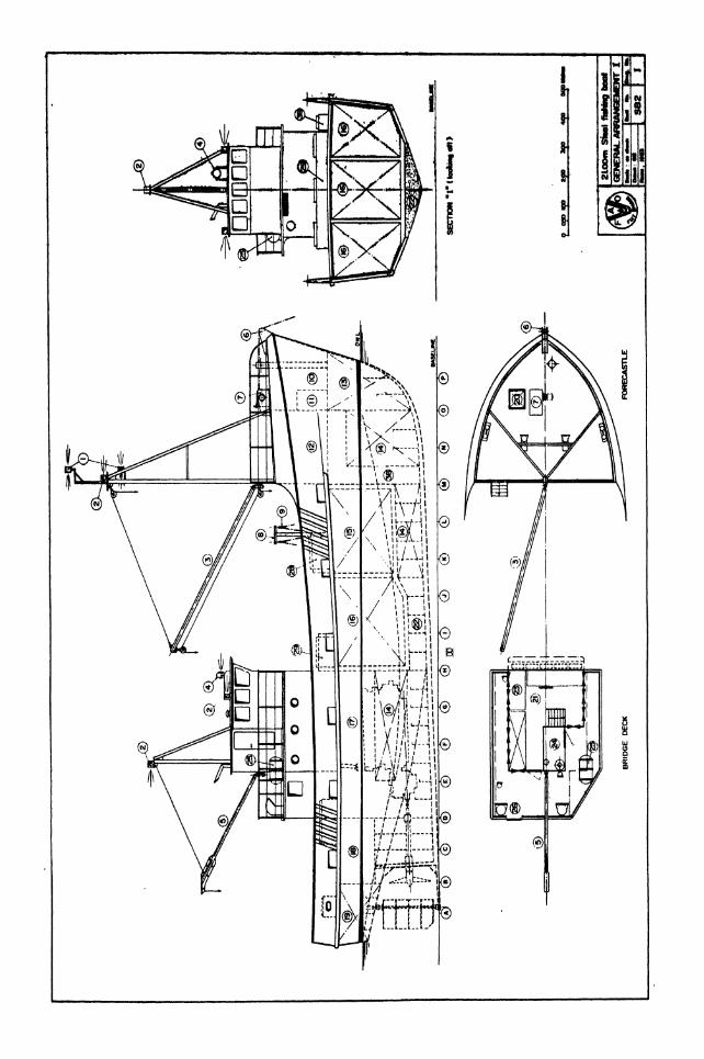
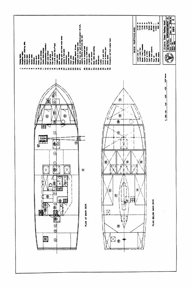
!i
iiiiiiilliiliiilJiiiii,!:!
8*S a~
N2* n 8R
in
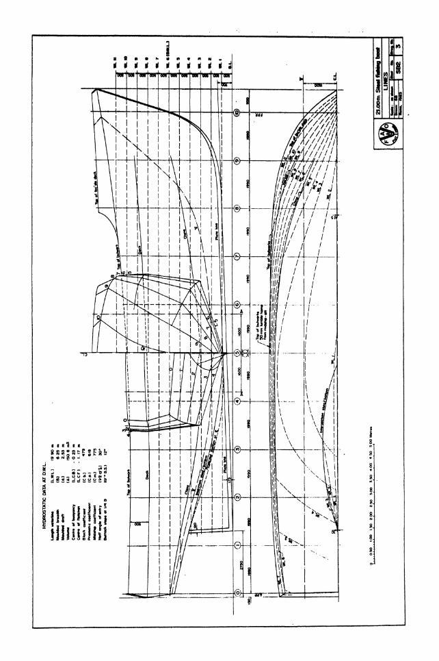
a 8iitititiitii
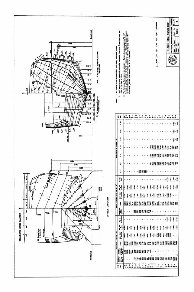
i
!j!
I", 2.
ij!
i 1 Jj!I
"
> *
If
i 1! iK!
*iill
11
H
S, C
HI!..a ;
SIM
tiooa
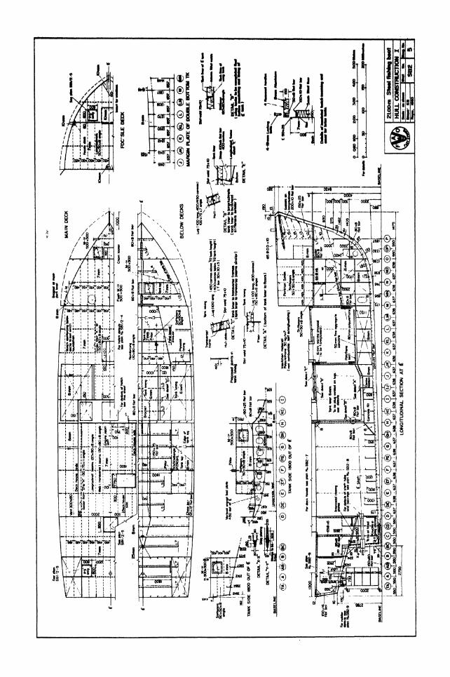
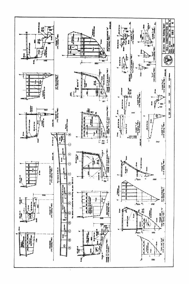
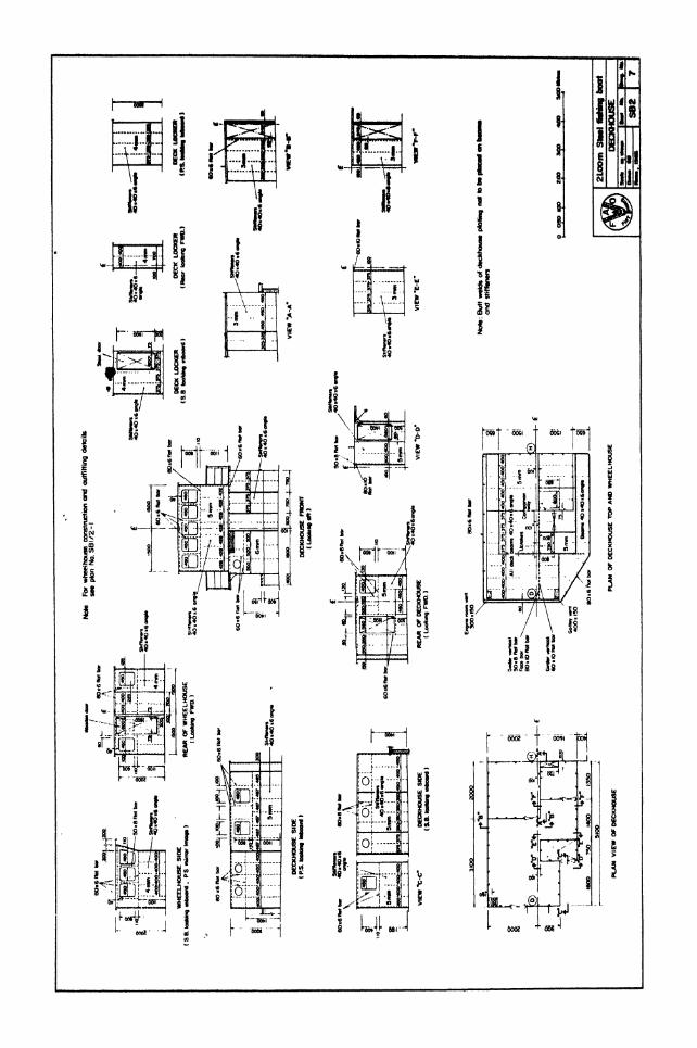
:r
i
S!
nii si .
4-"-p4f Hi Irr 1 II
ir-fe) P
""^a- i
oiV~
-'-
f y
i
it
ii
i
i
<*
i-f -w-N
W"(XXK
"*"<50S
*"
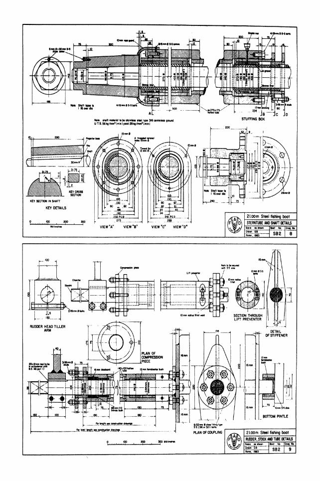
VIEW "A" VIEWMB" VIEW
MC" VIEW'D"
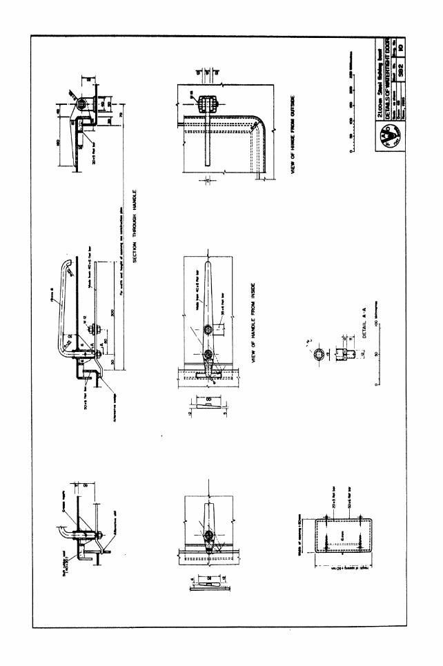
H4-
i
<m
\
i t
i t
r-H-H! t
JiL..r|
J
L.jj^.. .-.?;.-<
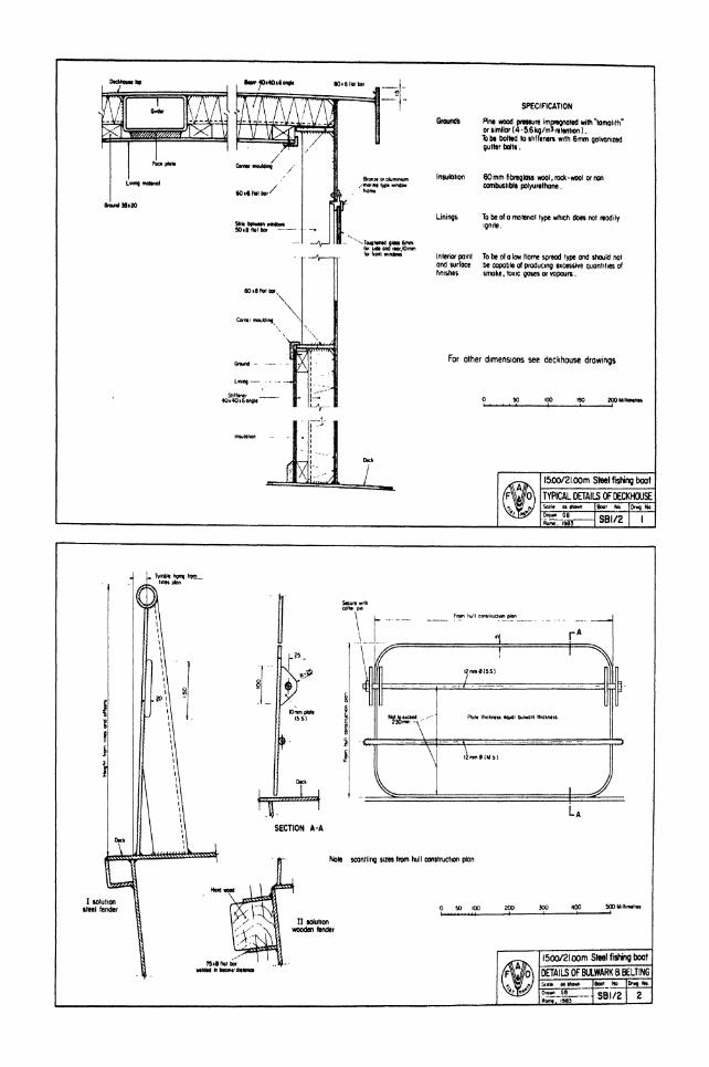
SPECIFICATION
Grounds Pine woodPine wood pressure impregnoted with "tomohth"or similar (4-5,6 kg/m* retention ) .
To be bolted to stiffeners with 6mm galvanized
gutter bolls.
Insulation 60mm fibreglass wool , rock -wool or non
combustible polyurethane .
Linings To be of a material type which does not readily
ignite.
Interior point To be of a low flame spread type and should not
and surface be capable of producing excessive quantities of
finishes smoke , toxic gases or vapours .
For other dimensions see deckhouse drawings
90 100 ISO 2001
I5.00/2l.00m Sfeel fishing boat
TYPICAL DETAILS OF DECKHOUSEi onhown
[BootNo {frag Ho"
r-Si SBI/2 I
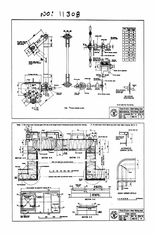
Notes Uffehhatrtcovvtoteequippidwilhontorhtthingeda^ 2) for other small holch details tee small hatch detail drawing SB 1/2 -5
M
COVER CORNER DETAILS
02040y OO
!5.00/2IXX)m Steel fishing boot
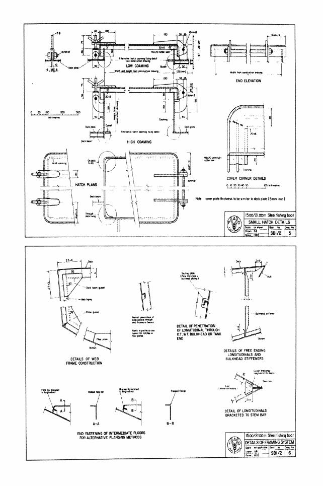
DETAILS OF WEBFRAME CONSTRUCTION
Notch In prod* * alto
iMxcal for notch** mfloor plain
END FASTENING OF INTERMEDIATE FLOORS
FOR ALTERNATIVE FLANGING METHODS
DETAIL OF PENETRATIONOF LONGITUDINAL THROUGH
O.T.WT. BULKHEAD OR TANK
END
DETAILS OF FREE ENDING
LONGITUDINALS ANDBULKHEAD STIFFENERS
DETAIL OF LONGITUDINALS
BRACKETED TO STEM BAR
1 500/21 COm Steel fishing boat
DETAILS OF FRAMING SYSTEMBoat No
SBI/2