Fisher 2052 Diaphragm Rotary Actuator - emerson.com · Operational Lockout(2) Available for...
20
www.Fisher.com Fisher ™ 2052 Diaphragm Rotary Actuator Contents Introduction 1 ................................. Scope of Manual 1 ............................. Description 1 ................................. Educational Services 4 ........................... Specifications 4 ............................... Installation 4 .................................. Actuator Mounting 5 .......................... Maintenance 7 ................................. Replacing Diaphragm 8 ........................ Replacing Diaphragm Plate, Diaphragm Rod Assembly, and Spring(s) 9 ...... Changing Or Replacing Actuator Lever 11 ......... Positioner Mounting (3610, DVC6020, or DVC6200) 12 ............. Top‐Mounted Handwheel 12 .................... Locking Mechanism 13 ......................... Parts Ordering 17 ............................... Parts List 17 ................................... Figure 1. Fisher Control‐Disk™ Valve with 2052 Actuator and DVC6200 Digital Valve Controller W9418-2 Introduction Scope of Manual This instruction manual includes installation, adjustment, operation, maintenance, and parts information for the Fisher 2052 diaphragm rotary actuator (figure 1). Instructions for the control valve, positioner, manual actuator, and other accessories are included in separate manuals. Do not install, operate, or maintain a 2052 actuator without being fully trained and qualified in valve, actuator, and accessory installation, operation, and maintenance. To avoid personal injury or property damage, it is important to carefully read, understand, and follow all the contents of this manual, including all safety cautions and warnings. If you have any questions about these instructions, contact your Emerson sales office or Local Business Partner before proceeding. Description 2052 spring‐and‐diaphragm rotary actuators are used on rotary‐shaft valve bodies for throttling or on‐off applications. The 2052 may be used for on‐off service without a positioner, or it may be used for throttling service with a positioner, depending on service conditions. The 2052 has an ISO 5211 mating interface that allows installation to non‐Fisher valves. Refer to separate bulletins for valve and positioner information. A top-mounted handwheel option is available for infrequent service as a manual actuator. For repeated or daily manual operation, the unit should be equipped with a side-mounted declutchable 1078 manual actuator. Externally adjustable travel stops are used to limit the degree of rotation at both ends of the actuator stroke. The lever for the 2052 actuator is supported by bushings. The lever may be changed to accommodate valve bodies with different size valve shafts. Instruction Manual D103296X012 2052 Actuator June 2017
Transcript of Fisher 2052 Diaphragm Rotary Actuator - emerson.com · Operational Lockout(2) Available for...

www.Fisher.com
Fisher™ 2052 Diaphragm Rotary Actuator
ContentsIntroduction 1. . . . . . . . . . . . . . . . . . . . . . . . . . . . . . . . .
Scope of Manual 1. . . . . . . . . . . . . . . . . . . . . . . . . . . . .Description 1. . . . . . . . . . . . . . . . . . . . . . . . . . . . . . . . .Educational Services 4. . . . . . . . . . . . . . . . . . . . . . . . . . .Specifications 4. . . . . . . . . . . . . . . . . . . . . . . . . . . . . . .
Installation 4. . . . . . . . . . . . . . . . . . . . . . . . . . . . . . . . . .Actuator Mounting 5. . . . . . . . . . . . . . . . . . . . . . . . . .
Maintenance 7. . . . . . . . . . . . . . . . . . . . . . . . . . . . . . . . .Replacing Diaphragm 8. . . . . . . . . . . . . . . . . . . . . . . .Replacing Diaphragm Plate,
Diaphragm Rod Assembly, and Spring(s) 9. . . . . .Changing Or Replacing Actuator Lever 11. . . . . . . . .Positioner Mounting
(3610, DVC6020, or DVC6200) 12. . . . . . . . . . . . .Top‐Mounted Handwheel 12. . . . . . . . . . . . . . . . . . . .Locking Mechanism 13. . . . . . . . . . . . . . . . . . . . . . . . .
Parts Ordering 17. . . . . . . . . . . . . . . . . . . . . . . . . . . . . . .Parts List 17. . . . . . . . . . . . . . . . . . . . . . . . . . . . . . . . . . .
Figure 1. Fisher Control‐Disk™ Valve with 2052 Actuator and DVC6200 Digital Valve Controller
W9418-2
Introduction
Scope of ManualThis instruction manual includes installation, adjustment, operation, maintenance, and parts information for theFisher 2052 diaphragm rotary actuator (figure 1). Instructions for the control valve, positioner, manual actuator, andother accessories are included in separate manuals.
Do not install, operate, or maintain a 2052 actuator without being fully trained and qualified in valve, actuator, andaccessory installation, operation, and maintenance. To avoid personal injury or property damage, it is important tocarefully read, understand, and follow all the contents of this manual, including all safety cautions and warnings. If youhave any questions about these instructions, contact your Emerson sales office or Local Business Partner beforeproceeding.
Description2052 spring‐and‐diaphragm rotary actuators are used on rotary‐shaft valve bodies for throttling or on‐off applications.The 2052 may be used for on‐off service without a positioner, or it may be used for throttling service with a positioner,depending on service conditions. The 2052 has an ISO 5211 mating interface that allows installation to non‐Fishervalves. Refer to separate bulletins for valve and positioner information.
A top-mounted handwheel option is available for infrequent service as a manual actuator. For repeated or daily manualoperation, the unit should be equipped with a side-mounted declutchable 1078 manual actuator. Externally adjustabletravel stops are used to limit the degree of rotation at both ends of the actuator stroke.
The lever for the 2052 actuator is supported by bushings. The lever may be changed to accommodate valve bodieswith different size valve shafts.
Instruction ManualD103296X012
2052 ActuatorJune 2017

Instruction ManualD103296X012
2052 ActuatorJune 2017
2
Table 1. Fisher 2052 Actuator SpecificationsSpecifications
Actuator Mounting ConnectionsSplined shaft connection, ISO 5211 actuator‐to‐bracket connectionSize 1: F07, Size 2: F10, Size 3: F14
Actuator Sizes See table 2
Operating Pressure(1) See table 3
Maximum Diaphragm Casing Pressure Size 1, 2, and 3 Actuators: 5 barg (73 psig)
Pressure Connection See table 5
Torque Output See table 3
Actuator Temperature Capabilities(1) Standard: -45 to 80�C (-50 to 176�F)Optional: -45 to 100�C (-50 to 212�F)(3) or -60 to 80�C (-76 to 176�F)(4)
Operation Field reversible between PDTC and PDTO; right‐ and left‐hand mounting, any angle of orientation
Approximate WeightSize 1: 22.2 kg (49 lb)Size 2: 54.4 kg (120 lb)Size 3: 113 kg (250 lb)
Controller/Positioners Available DVC2000, DVC6020, DVC6030, DVC6200, 3610J, 3620J, 4190, C1
Adjustable Travel Stops Standard adjustable up and down stops capable of 30 degrees of adjustment per stop.
Accessories Available 846, 646, 2625, and 67C Series, switches, i2P-100, VBL, DXP, GO Switch™
HandwheelTop‐mounted handwheel: Optional on Size 1, 2, and 3 actuatorsDeclutchable handwheel: Optional on Size 1, 2, and 3 actuators
Operational Lockout(2) Available for customer‐supplied padlock to lock the actuator in the spring‐fail position
1. The pressure/temperature limits in this manual should not be exceeded. The current SIL certification for the 2052 actuator is only relevant for the standard temperature ratings shown.2. Lockout and declutchable handwheel cannot be used together on size 2 and size 3 actuators.3. Temperature range only applies when using silicone diaphragm material. Silicone diaphragm is not available with the top-mounted handwheel option.4. Temperature range requires use of stainless steel bolting for yoke and travel stops. Not available with top-mounted handwheel.
Table 2. Actuator and Shaft Size AvailabilitySHAFT SIZE ACTUATOR SIZE
mm Inches 1 2 3
12.7 1/2 X
14.3 x 15.9 9/16 x 5/8 X X
15.9 5/8 X X
19.1 3/4 X X X
22.2 7/8 X X
25.4 1 X X
28.6 x 31.8 1-1/8 x 1-1/4 X X
31.8 1-1/4 X X
31.8 x 38.1 1-1/4 x 1-1/2 X
38.1 1-1/2 X
39.7 x 44.5 1-9/16 x 1-3/4 X
44.5 1-3/4 X
50.8 2 X
Table 3. Torque versus Actuator Size
ACTUATORSIZE ANDACTION
OPERATING PRESSURE
2 barg (29 psig)(1) 3 barg (44 psig)(1) 4 barg (58 psig)(1) 4.7 barg (68 psig)(1)
Torque
N�m lbf�in N�m lbf�in N�m lbf�in N�m lbf�in
1 (PDTO)
1 (PDTC)
25.5
25.5
226
226
25.5
36.2
226
320
51.2
51.2
453
453
51.2
72.4
453
641
2 (PDTO)
2 (PDTC)
105
105
930
930
105
175
930
1550
210
210
1860
1860
210
320
1860
2840
3 (PDTO) 327 2890 327 2890 631 5580 631 5580
3 (PDTC) 280 2480 557 4930 584 5170 930 8230
1. Do not interpolate between operating pressures. Consult your Emerson sales office or Local Business Partner for assistance.
Instruction ManualD103296X012
2052 ActuatorJune 2017
3
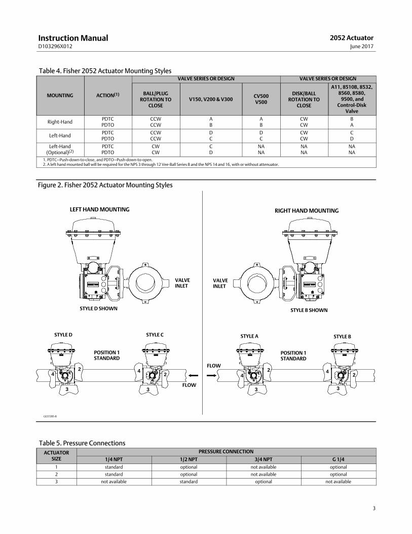
Table 4. Fisher 2052 Actuator Mounting Styles
MOUNTING ACTION(1)
VALVE SERIES OR DESIGN VALVE SERIES OR DESIGN
BALL/PLUGROTATION TO
CLOSEV150, V200 & V300
CV500V500
DISK/BALLROTATION TO
CLOSE
A11, 8510B, 8532,8560, 8580, 9500, and
Control‐DiskValve
Right‐HandPDTCPDTO
CCWCCW
AB
AB
CWCW
BA
Left‐HandPDTCPDTO
CCWCCW
DC
DC
CWCW
CD
Left‐Hand(Optional)(2)
PDTCPDTO
CWCW
CD
NANA
NANA
NANA
1. PDTC—Push‐down‐to‐close, and PDTO—Push‐down‐to‐open.2. A left hand mounted ball will be required for the NPS 3 through 12 Vee-Ball Series B and the NPS 14 and 16, with or without attenuator.
Figure 2. Fisher 2052 Actuator Mounting Styles
STYLE ASTYLE C STYLE BSTYLE D
FLOW
2
3
4 2
3
4
POSITION 1STANDARD
POSITION 1STANDARD
4 4
3 3
2 2
GE37285-B
FLOW
STYLE D SHOWN
LEFT HAND MOUNTING
VALVEINLET
STYLE B SHOWN
VALVEINLET
RIGHT HAND MOUNTING
Table 5. Pressure Connections
ACTUATORSIZE
PRESSURE CONNECTION
1/4 NPT 1/2 NPT 3/4 NPT G 1/4
1 standard optional not available optional
2 standard optional not available optional
3 not available standard optional not available
Instruction ManualD103296X012
2052 ActuatorJune 2017
4
Educational ServicesFor information on available courses for Fisher 2052 actuators, as well as a variety of other products, contact:
Emerson Automation SolutionsEducational Services - RegistrationPhone: 1-641-754-3771 or 1-800-338-8158E-mail: [email protected]/fishervalvetraining
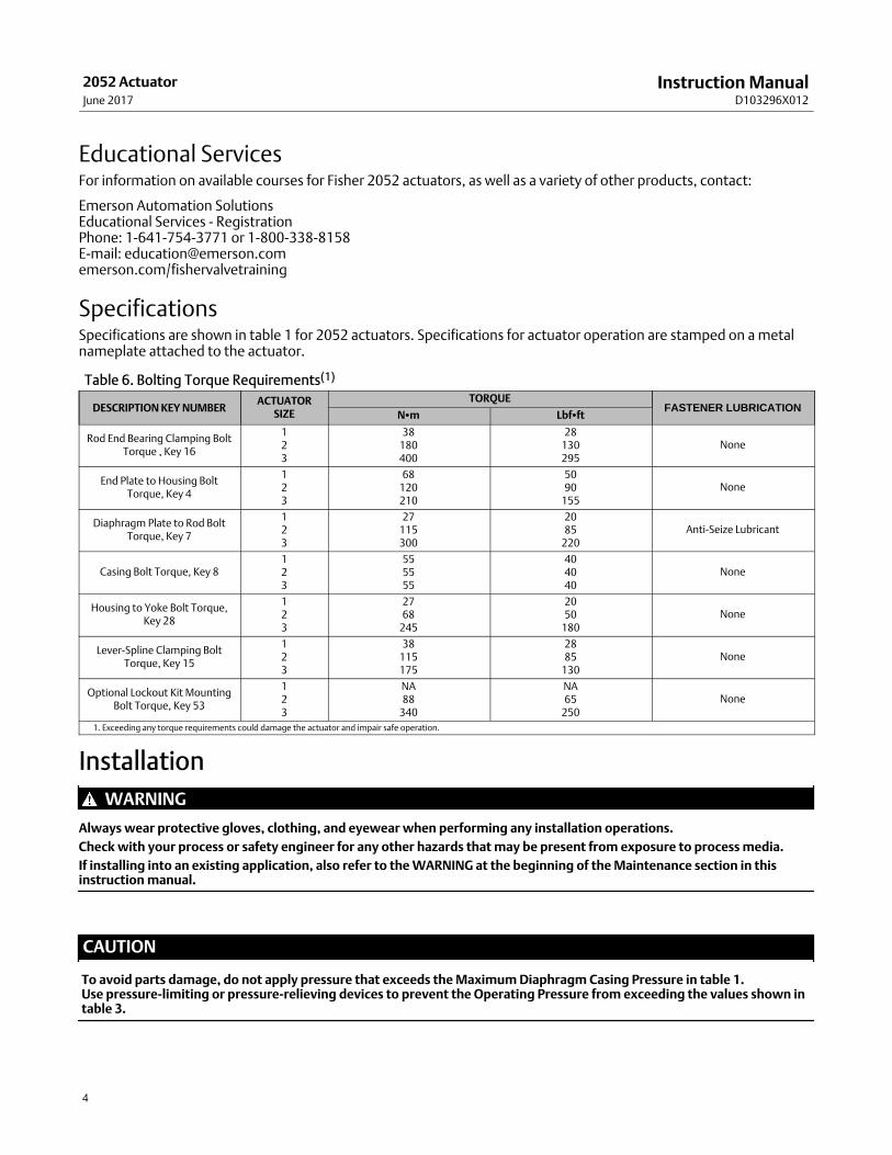
SpecificationsSpecifications are shown in table 1 for 2052 actuators. Specifications for actuator operation are stamped on a metalnameplate attached to the actuator.
Table 6. Bolting Torque Requirements(1)
DESCRIPTION KEY NUMBERACTUATOR
SIZE
TORQUEFASTENER LUBRICATION
N�m Lbf�ft
Rod End Bearing Clamping BoltTorque , Key 16
123
38180400
28130295
None
End Plate to Housing BoltTorque, Key 4
123
68120210
5090
155None
Diaphragm Plate to Rod BoltTorque, Key 7
123
27115300
2085
220Anti-Seize Lubricant
Casing Bolt Torque, Key 8123
555555
404040
None
Housing to Yoke Bolt Torque,Key 28
123
2768
245
2050
180None
Lever‐Spline Clamping BoltTorque, Key 15
123
38115175
2885
130None
Optional Lockout Kit MountingBolt Torque, Key 53
123
NA88
340
NA65
250None
1. Exceeding any torque requirements could damage the actuator and impair safe operation.
Installation
WARNING
Always wear protective gloves, clothing, and eyewear when performing any installation operations.
Check with your process or safety engineer for any other hazards that may be present from exposure to process media.
If installing into an existing application, also refer to the WARNING at the beginning of the Maintenance section in thisinstruction manual.
CAUTION
To avoid parts damage, do not apply pressure that exceeds the Maximum Diaphragm Casing Pressure in table 1. Use pressure‐limiting or pressure‐relieving devices to prevent the Operating Pressure from exceeding the values shown intable 3.

Instruction ManualD103296X012
2052 ActuatorJune 2017
5
The actuator, as it comes from the factory, is normally mounted on a valve body. If the actuator is shipped separatelyor if it is necessary to mount the actuator on the valve, perform the procedures presented in the Actuator Mountingsection. Follow the procedures given in the valve instruction manual when installing the control valve in the pipeline.
If a positioner is ordered with the actuator, the pressure connection to the actuator is normally made at the factory. Ifit is necessary to make this connection, run tubing of the appropriate size for the diaphragm casing pressureconnection (reference table 5) between the pressure connection and the instrument. Keep the length of tubing orpipe as short as possible to avoid transmission lag in the control signal.
When the control valve is completely installed and connected to the controlling instrument, check to make sure thatthe action is correct (air‐to‐open or air‐to‐close) and that the controlling instrument is properly configured for thedesired action. For successful operation, the diaphragm rod assembly, lever, and valve shaft must move freely inresponse to changes in the loading pressure on the diaphragm.
Actuator Mounting
WARNING
Avoid personal injury or property damage from sudden release of process pressure or bursting of parts. Before performingany maintenance operations:
� Do not remove the actuator from the valve while the valve is still pressurized.
� Always wear protective gloves, clothing, and eyewear when performing any maintenance operations.
� Disconnect any operating lines providing air pressure, electric power, or a control signal to the actuator. Be sure theactuator cannot suddenly open or close the valve.
� Use bypass valves or completely shut off the process to isolate the valve from process pressure. Relieve process pressurefrom both sides of the valve. Drain the process media from both sides of the valve.
� Safely vent the power actuator loading pressure.
� Use lock‐out procedures to be sure that the above measures stay in effect while you work on the equipment.
� The valve packing box may contain process fluids that are pressurized, even when the valve has been removed from thepipeline. Process fluids may spray out under pressure when removing the packing hardware or packing rings.
� Check with your process or safety engineer for any hazards that may be present from exposure to process media.
Use the following steps to mount the actuator or to change actuator mounting style or position.
Unless otherwise specified, key numbers referenced in the following procedures are shown in figure 7 for the 2052actuator.
If the Actuator is mounted on a valve body and it is necessary to change mounting style or position, the actuator mustfirst be separated from the valve body.
1. Isolate the valve body from the process. Release process pressure and vent all actuator pressure.
2. Remove the cover or plug (key 2).
WARNING
To avoid personal injury and equipment damage from moving parts, keep fingers and tools clear while stroking theactuator with the cover removed.

Instruction ManualD103296X012
2052 ActuatorJune 2017
6
3. Loosen the cap screw (key 15).
4. Separate the actuator from the valve body by removing the cap screws and nuts which secure the valve to themounting yoke (key 27). Proceed to step 5.
If the actuator is not mounted on a valve body ensure the up and down travel stops (see figure 3) are adjustedcorrectly to achieve the desired actuator rotation. Use the travel indicator (key 21) and travel scale (key 19) asreference.
Note
Once each travel stop is properly positioned, adequately tighten the hex nut (key 24) to lock the travel stop in place.
5. Refer to figure 2 and table 4 for available mounting styles and positions. The actuator is normally positionedvertically with the valve in a horizontal pipeline.
6. Determine whether the actuator mounting yoke (key 27) will be mounted on the end plate assembly (key 3) side oron the actuator housing boss side of the actuator. If the desired mounting position and style require moving themounting yoke (key 27) and travel indicator components to opposite sides of the actuator, remove the machinescrews (keys 20 and 22), the travel indicator scale (key 19), and the travel indicator (key 21). Remove the cap screws(key 28) and the mounting yoke (key 27). Install the mounting yoke in the desired position (on the end plateassembly or on the actuator housing boss). Tighten the mounting cap screws to the torque specified in table 6.Install the travel indicator components on the opposite side of the actuator.
WARNING
To avoid personal injury or property damage, ensure the travel indicator is installed correctly to coincide with the desiredactuator action. Refer to figure 3 for more information.
Figure 3. Fisher 2052 Actuator Travel Stops and Travel Indication
TRAVEL INDICATORSCALE
UPTRAVELSTOP
DOWNTRAVELSTOP
KEY 22
KEY 20 TRAVELINDICATOR
INDICATORORIENTATIONFOR PDTC
INDICATORORIENTATIONFOR PDTO
VIEW A
VIEW A
Instruction ManualD103296X012
2052 ActuatorJune 2017
7
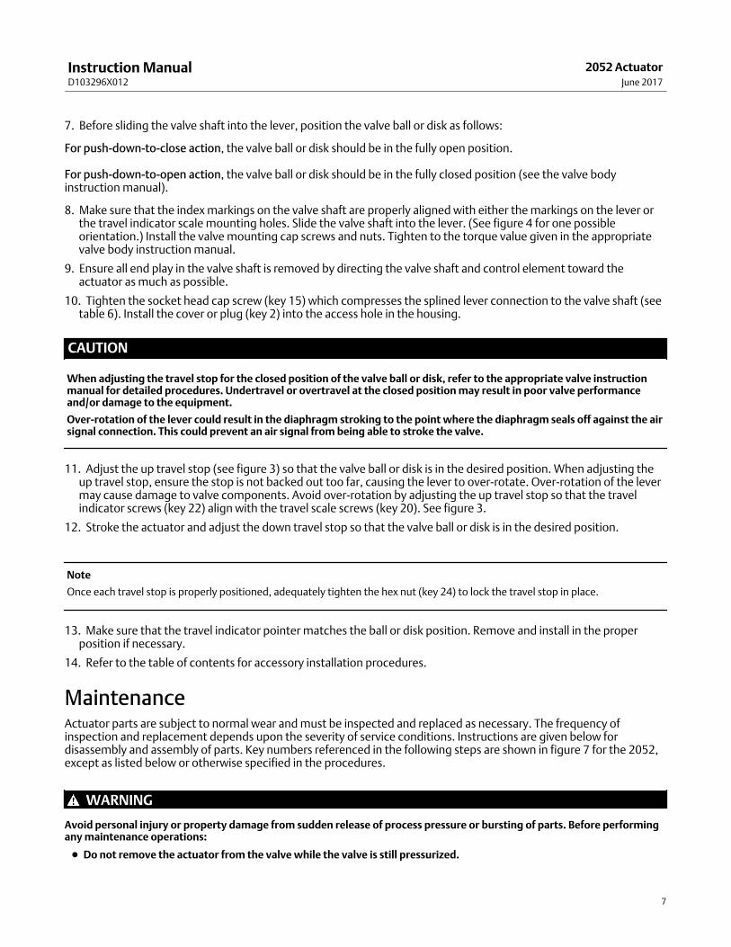
7. Before sliding the valve shaft into the lever, position the valve ball or disk as follows:
For push‐down‐to‐close action, the valve ball or disk should be in the fully open position.
For push‐down‐to‐open action, the valve ball or disk should be in the fully closed position (see the valve bodyinstruction manual).
8. Make sure that the index markings on the valve shaft are properly aligned with either the markings on the lever orthe travel indicator scale mounting holes. Slide the valve shaft into the lever. (See figure 4 for one possibleorientation.) Install the valve mounting cap screws and nuts. Tighten to the torque value given in the appropriatevalve body instruction manual.
9. Ensure all end play in the valve shaft is removed by directing the valve shaft and control element toward theactuator as much as possible.
10. Tighten the socket head cap screw (key 15) which compresses the splined lever connection to the valve shaft (seetable 6). Install the cover or plug (key 2) into the access hole in the housing.
CAUTION
When adjusting the travel stop for the closed position of the valve ball or disk, refer to the appropriate valve instructionmanual for detailed procedures. Undertravel or overtravel at the closed position may result in poor valve performanceand/or damage to the equipment.
Over-rotation of the lever could result in the diaphragm stroking to the point where the diaphragm seals off against the airsignal connection. This could prevent an air signal from being able to stroke the valve.
11. Adjust the up travel stop (see figure 3) so that the valve ball or disk is in the desired position. When adjusting theup travel stop, ensure the stop is not backed out too far, causing the lever to over-rotate. Over-rotation of the levermay cause damage to valve components. Avoid over-rotation by adjusting the up travel stop so that the travelindicator screws (key 22) align with the travel scale screws (key 20). See figure 3.
12. Stroke the actuator and adjust the down travel stop so that the valve ball or disk is in the desired position.
Note
Once each travel stop is properly positioned, adequately tighten the hex nut (key 24) to lock the travel stop in place.
13. Make sure that the travel indicator pointer matches the ball or disk position. Remove and install in the properposition if necessary.
14. Refer to the table of contents for accessory installation procedures.
MaintenanceActuator parts are subject to normal wear and must be inspected and replaced as necessary. The frequency ofinspection and replacement depends upon the severity of service conditions. Instructions are given below fordisassembly and assembly of parts. Key numbers referenced in the following steps are shown in figure 7 for the 2052,except as listed below or otherwise specified in the procedures.
WARNING
Avoid personal injury or property damage from sudden release of process pressure or bursting of parts. Before performingany maintenance operations:
� Do not remove the actuator from the valve while the valve is still pressurized.

Instruction ManualD103296X012
2052 ActuatorJune 2017
8
� Always wear protective gloves, clothing, and eyewear when performing any maintenance operations.
� Disconnect any operating lines providing air pressure, electric power, or a control signal to the actuator. Be sure theactuator cannot suddenly open or close the valve.
� Use bypass valves or completely shut off the process to isolate the valve from process pressure. Relieve process pressurefrom both sides of the valve. Drain the process media from both sides of the valve.
� Safely vent the power actuator loading pressure.
� Use lock‐out procedures to be sure that the above measures stay in effect while you work on the equipment.
� Check with your process or safety engineer for any hazards that may be present from exposure to process media.
Replacing DiaphragmIsolate the valve body from the process. Release process pressure and vent all actuator pressure.
Disassembly1. Remove the supply tubing or pipe from the top casing assembly (key 5).
WARNING
To avoid personal injury from precompressed spring force suddenly thrusting parts away from the actuator, springcompression must first be relieved. Closely follow the instructions below.
Figure 4. Orientation of the Fisher 2052 Actuator Lever into the Housing and Aligning the Actuator to the Valve ShaftMarkings
UP TRAVEL STOP
2. Loosen, but do not remove, all casing cap screws and hex nuts (keys 8 and 9). Ensure there is no spring force to thetop casing assembly (key 5). If spring force is detected against the top casing assembly, ensure the up travel stopcap screw (key 23) is adjusted correctly to prevent over-rotation of the lever (key 14). Refer to figure 3. The travelindicator screws (key 22) in the end of the lever should be in alignment with the travel scale screws (key 20). If theup travel stop is confirmed to be adjusted correctly and force is still detected against the top casing assembly,contact your local Emerson Automation Solutions Instrument and Valves Service Center. Alternatively, replace twooppositely located casing cap screws (key 8) with 100 mm (4 inch) long fully threaded M10 cap screws of ISO 898-1
Instruction ManualD103296X012
2052 ActuatorJune 2017
9
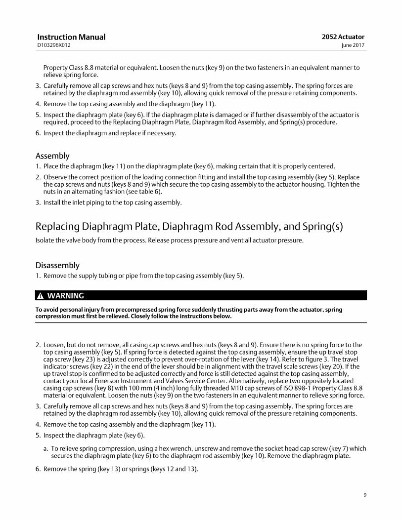
Property Class 8.8 material or equivalent. Loosen the nuts (key 9) on the two fasteners in an equivalent manner torelieve spring force.
3. Carefully remove all cap screws and hex nuts (keys 8 and 9) from the top casing assembly. The spring forces areretained by the diaphragm rod assembly (key 10), allowing quick removal of the pressure retaining components.
4. Remove the top casing assembly and the diaphragm (key 11).
5. Inspect the diaphragm plate (key 6). If the diaphragm plate is damaged or if further disassembly of the actuator isrequired, proceed to the Replacing Diaphragm Plate, Diaphragm Rod Assembly, and Spring(s) procedure.
6. Inspect the diaphragm and replace if necessary.
Assembly1. Place the diaphragm (key 11) on the diaphragm plate (key 6), making certain that it is properly centered.
2. Observe the correct position of the loading connection fitting and install the top casing assembly (key 5). Replacethe cap screws and nuts (keys 8 and 9) which secure the top casing assembly to the actuator housing. Tighten thenuts in an alternating fashion (see table 6).
3. Install the inlet piping to the top casing assembly.
Replacing Diaphragm Plate, Diaphragm Rod Assembly, and Spring(s)Isolate the valve body from the process. Release process pressure and vent all actuator pressure.
Disassembly1. Remove the supply tubing or pipe from the top casing assembly (key 5).
WARNING
To avoid personal injury from precompressed spring force suddenly thrusting parts away from the actuator, springcompression must first be relieved. Closely follow the instructions below.
2. Loosen, but do not remove, all casing cap screws and hex nuts (keys 8 and 9). Ensure there is no spring force to thetop casing assembly (key 5). If spring force is detected against the top casing assembly, ensure the up travel stopcap screw (key 23) is adjusted correctly to prevent over-rotation of the lever (key 14). Refer to figure 3. The travelindicator screws (key 22) in the end of the lever should be in alignment with the travel scale screws (key 20). If theup travel stop is confirmed to be adjusted correctly and force is still detected against the top casing assembly,contact your local Emerson Instrument and Valves Service Center. Alternatively, replace two oppositely locatedcasing cap screws (key 8) with 100 mm (4 inch) long fully threaded M10 cap screws of ISO 898-1 Property Class 8.8material or equivalent. Loosen the nuts (key 9) on the two fasteners in an equivalent manner to relieve spring force.
3. Carefully remove all cap screws and hex nuts (keys 8 and 9) from the top casing assembly. The spring forces areretained by the diaphragm rod assembly (key 10), allowing quick removal of the pressure retaining components.
4. Remove the top casing assembly and the diaphragm (key 11).
5. Inspect the diaphragm plate (key 6).
a. To relieve spring compression, using a hex wrench, unscrew and remove the socket head cap screw (key 7) whichsecures the diaphragm plate (key 6) to the diaphragm rod assembly (key 10). Remove the diaphragm plate.
6. Remove the spring (key 13) or springs (keys 12 and 13).

Instruction ManualD103296X012
2052 ActuatorJune 2017
10
7. The guide assembly (key 48) may be removed for inspection (size 3 only).
Note
At this stage of disassembly, it may be determined that further disassembly is not necessary. If separation of the diaphragm rodassembly from the lever is not warranted, proceed to the Assembly portion within this section of the procedure.
8. To gain access to the cap screw (key 16) which secures the diaphragm rod assembly to the lever, the end plateassembly (key 3) must be removed. Before the end plate assembly can be removed, one of the followingprocedures must be performed. Proceed as appropriate:
� For actuators with valve bodies mounted on the end plate assembly (key 3) side of the actuator, the actuator mustbe separated from the valve body. Perform steps 1 through 4 of the Actuator Mounting section, remove themounting yoke (key 27), and then return to step 9 of this section.
� For actuators with valve bodies mounted on the actuator housing boss side of the actuator [opposite of theendplate (key 3)], remove the travel indicator pointer (key 21). Proceed to step 9.
9. Remove the socket head cap screws (key 4) and the end plate assembly (key 3).
10. Remove the cap screw (key 16) and nut (key 17) if applicable (size 3 only), that secures the actuator lever (key 14)to the diaphragm rod assembly (key 10). Remove the diaphragm rod assembly.
11. Inspect all parts and replace if necessary.
12. If total disassembly of the actuator is required, or if the actuator will be assembled for use with a valve body with adifferent valve shaft diameter, proceed to the Changing or Replacing Actuator Lever procedure.
Assembly1. Fasten the diaphragm rod assembly (key 10) to the lever using the cap screw (key 16) and nut (key 17) if applicable.
Tighten per table 6.
2. Install the housing end plate (key 3).
3. Adjust the travel stop bolts to the correct position so that the travel indicator screws (key 22) align with the travelscale screws (key 20). See figure 3.
4. Install the guide assembly (key 48 - size 3 only).
5. Install the spring(s). The outer (larger diameter) spring is standard for the single spring size 1 & 2 constructions. Theinner spring is standard for the single spring size 3 construction.
6. Place the diaphragm plate (key 6) onto the spring(s). It is important that the springs be properly seated in theirrespective counterbores on the bottom side of the plate. If necessary, push or pull the diaphragm plate towardcenter to ensure the springs are engaged into their respective seats.
7. Lubricate the socket head capscrew (key 7) and tighten per table 6.
8. Place the diaphragm (key 11) on the diaphragm plate (key 6), making certain that it is properly centered.
9. Observe the correct position of the loading connection fitting and install the top casing assembly (key 5). Replacethe cap screws and nuts (keys 8 and 9) which secure the top casing assembly to the actuator housing. Tighten thenuts in an alternating fashion (see table 6).
10. Install the inlet piping to the top casing assembly.
11. Install the travel indicator (key 19) if removed.
12. If the actuator was removed from the valve body, refer to the appropriate section in the Actuator Mountingprocedure and proceed as applicable.

Instruction ManualD103296X012
2052 ActuatorJune 2017
11
Changing or Replacing Actuator Lever
WARNING
Avoid personal injury or property damage. The end plate assembly (key 3) and lever (key 14) may only be removed after theactuator spring compression forces are safely relieved. Refer to the instructions below.
Disassembly
WARNING
Avoid personal injury or property damage from sudden release of process pressure or bursting of parts. Before performingany maintenance operations:
� Do not remove the actuator from the valve while the valve is still pressurized.
� Always wear protective gloves, clothing, and eyewear when performing any maintenance operations.
� Disconnect any operating lines providing air pressure, electric power, or a control signal to the actuator. Be sure theactuator cannot suddenly open or close the valve.
� Use bypass valves or completely shut off the process to isolate the valve from process pressure. Relieve process pressurefrom both sides of the valve. Drain the process media from both sides of the valve.
� Safely vent the power actuator loading pressure.
� Use lock‐out procedures to be sure that the above measures stay in effect while you work on the equipment.
� Check with your process or safety engineer for any other hazards that may be present from exposure to process media.
1. Isolate the valve body from the process. Release process pressure and vent all actuator pressure.
2. Remove the cover or plug (key 2).
WARNING
To avoid personal injury and equipment damage from moving parts, keep fingers and tools clear while stroking theactuator with the cover removed.
3. Loosen the cap screw (key 15).
4. Follow steps 2 through 10 in the Replacing Diaphragm Plate, Diaphragm Rod Assembly, and Spring(s) section.
5. Remove and inspect the lever (key 14). If the lever is worn or damaged, or if the actuator will be mounted to a valvebody requiring a different size lever, replace the lever.
6. Inspect the bushings located in the end plate (key 3) and housing (key 1) assemblies. If bushings are excessivelyworn or damaged, remove them with a press. Press in new bushings so that they are flush with the exterior surfacesof the actuator housing and the end plate assembly.
Assembly1. Refer to figure 4 for the correct orientation of the lever during assembly.
2. If a cam‐operated positioner is used, install the cam to the lever with the parts provided by the appropriateinstrument mounting kit. Be sure to observe the orientation shown in figure 4 and follow all procedures given in thepositioner instruction manual.
3. Insert the lever into the bushing in the actuator housing.
4. Fasten the rod end bearing diaphragm rod assembly to the lever using the cap screw (key 16) and nut (key 17) ifapplicable. Tighten per table 6.
Instruction ManualD103296X012
2052 ActuatorJune 2017
12
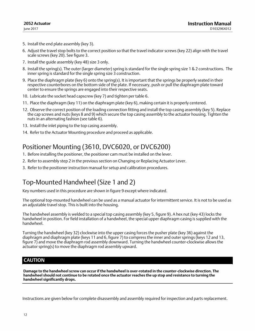
5. Install the end plate assembly (key 3).
6. Adjust the travel stop bolts to the correct position so that the travel indicator screws (key 22) align with the travelscale screws (key 20). See figure 3.
7. Install the guide assembly (key 48) size 3 only.
8. Install the spring(s). The outer (larger diameter) spring is standard for the single spring size 1 & 2 constructions. Theinner spring is standard for the single spring size 3 construction.
9. Place the diaphragm plate (key 6) onto the spring(s). It is important that the springs be properly seated in theirrespective counterbores on the bottom side of the plate. If necessary, push or pull the diaphragm plate towardcenter to ensure the springs are engaged into their respective seats.
10. Lubricate the socket head capscrew (key 7) and tighten per table 6.
11. Place the diaphragm (key 11) on the diaphragm plate (key 6), making certain it is properly centered.
12. Observe the correct position of the loading connection fitting and install the top casing assembly (key 5). Replacethe cap screws and nuts (keys 8 and 9) which secure the top casing assembly to the actuator housing. Tighten thenuts in an alternating fashion (see table 6).
13. Install the inlet piping to the top casing assembly.
14. Refer to the Actuator Mounting procedure and proceed as applicable.
Positioner Mounting (3610, DVC6020, or DVC6200)1. Before installing the positioner, the positioner cam must be installed on the lever.
2. Refer to assembly step 2 in the previous section on Changing or Replacing Actuator Lever.
3. Refer to the positioner instruction manual for setup and calibration procedures.
Top‐Mounted Handwheel (Size 1 and 2)Key numbers used in this procedure are shown in figure 9 except where indicated.
The optional top‐mounted handwheel can be used as a manual actuator for intermittent service. It is not to be used asan adjustable travel stop. This is built into the housing.
The handwheel assembly is welded to a special top casing assembly (key 5, figure 9). A hex nut (key 43) locks thehandwheel in position. For field installation of a handwheel, the special upper diaphragm casing is supplied with thehandwheel.
Turning the handwheel (key 32) clockwise into the upper casing forces the pusher plate (key 36) against thediaphragm and diaphragm plate (keys 11 and 6, figure 7) to compress the inner and outer springs (keys 12 and 13,figure 7) and move the diaphragm rod assembly downward. Turning the handwheel counter‐clockwise allows theactuator spring(s) to move the diaphragm rod assembly upward.
CAUTION
Damage to the handwheel screw can occur if the handwheel is over-rotated in the counter-clockwise direction. Thehandwheel should not continue to be rotated once the actuator reaches the up stop and resistance to turning thehandwheel significantly drops.
Instructions are given below for complete disassembly and assembly required for inspection and parts replacement.

Instruction ManualD103296X012
2052 ActuatorJune 2017
13
Disassembly
WARNING
To avoid personal injury from the precompressed spring force thrusting the upper diaphragm casing away from theactuator, fully turn the handwheel counterclockwise.
1. Perform steps 1 through 6 of the Replacing Diaphragm procedure.
2. Remove the cotter pin, hex nut, handwheel, and locknut (keys 34, 33, 32, and 43). Unscrew the stem (key 35) outthrough the actuator end of the handwheel body (key 5).
3. Check the condition of the O‐ring (key 44); replace if necessary.
4. If it is necessary to remove the pusher plate or spacer (key 36 or 42), drive out the groove pin (key 37).
Assembly1. Before assembling, lubricate the thread of the stem (key 35) with anti‐seize lubricant. Lubricate the bearing
surfaces of the stem and rounded end with lithium grease.
2. If the pusher plate or spacer was removed, attach them to the stem and drive in a new groove pin (key 37).
3. With the O‐ring (key 44) in place, thread the stem into the handwheel assembly.
4. Install the locknut, handwheel, hex nut, and cotter pin (keys 43, 32, 33, and 34).
Note
Be sure to install the handwheel so that the arrow of operation on the top side coincides with the action of the actuator, as statedon the nameplate. (The arrow should point clockwise for PDTO. The arrow should point counter-clockwise for PDTC.)
5. Install the top casing assembly, making certain the warning tag is in place on the casing flange.
Locking MechanismRefer to figures 5 or 6 for the appropriate size locking mechanism when installing or planning to operate the device.
WARNING
Avoid personal injury or property damage from sudden release of process pressure or bursting of parts. Before performingany maintenance operations:
� Do not remove the actuator from the valve while the valve is still pressurized.
� Always wear protective gloves, clothing, and eyewear when performing any maintenance operations.
� Disconnect any operating lines providing air pressure, electric power, or a control signal to the actuator. Be sure theactuator cannot suddenly open or close the valve.
� Use bypass valves or completely shut off the process to isolate the valve from process pressure. Relieve process pressurefrom both sides of the valve. Drain the process media from both sides of the valve.
� Safely vent the power actuator loading pressure.
� Check with your process or safety engineer for any hazards that may be present from exposure to process media.

Instruction ManualD103296X012
2052 ActuatorJune 2017
14
Installing the Size 1 Locking MechanismTo add the locking mechanism (figure 5) to an existing actuator, purchase the required kit from Emerson AutomationSolutions.
1. Ensure the diaphragm rod assembly (key 10) is in the upward position and the lever (key 14) is against the up travelstop (spring fail position).
2. Thread the supplied jam nut (key 40) all the way onto the threaded bolt portion of the mounting plate assembly.
3. Loosen the down travel stop hex nut (key 24) and remove the travel stop cap screw (key 23).
4. Remove the vent screen (key 47) from the threaded hole in the bottom of the actuator housing.
5. Secure the locking plate (key 39) to the bottom of the housing assembly by reinstalling the down travel stop (key23) and hex nut (key 24). Ensure the clearance hole in the locking plate is aligned with the threaded hole in thebottom of the housing.
6. Ensure the down travel stop is adjusted correctly to achieve the desired actuator rotational output.
7. Install the mounting plate assembly (key 38) by inserting it through the clearance hole in the locking plate andthreading it into the hole in the actuator housing.
GE51941_A
Figure 5. Size 1 Locking Mechanism
LOCKING PLATE (KEY 39)
MOUNTING PLATE ASSEMBLY(KEY 38)
JAM NUT(KEY 40)
CUSTOMER-SUPPLIEDLOCKING DEVICE
Operating the Locking Mechanism (Size 1)
To Lock the Actuator1. Screw the mounting plate assembly into the housing until it contacts the actuator lever.
2. Align the hole in the locking plate (key 39) with one of the holes in the disk of the mounting plate assembly.
3. Tighten the jam nut (key 40) against the locking plate.
Instruction ManualD103296X012
2052 ActuatorJune 2017
15
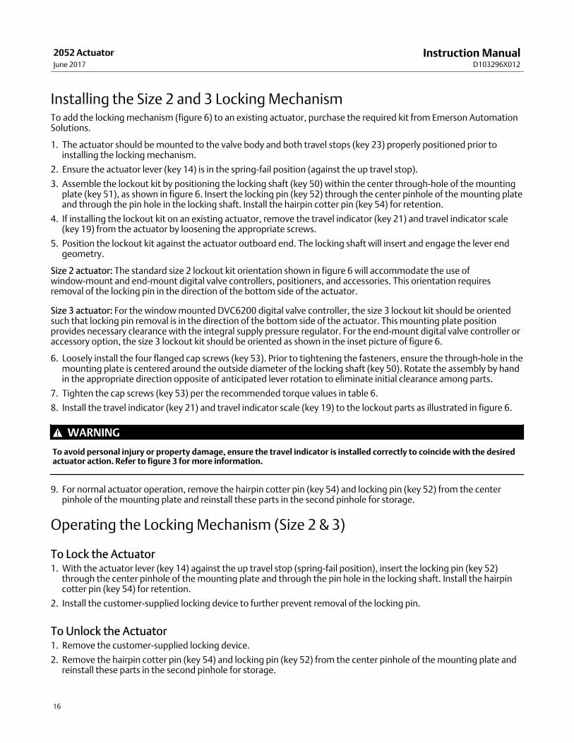
4. Insert a padlock (not furnished by Emerson Automation Solutions) to prevent the mounting plate assembly fromrotating.
To Unlock the Actuator1. Remove the padlock. Loosen the jam nut (key 40), and unscrew the threaded bolt until it no longer protrudes inside
the housing.
Note
Ensure the mounting plate assembly bolt is unthreaded far enough that the actuator lever will not contact the bolt during normalactuator operation.
2. If the mounting plate assembly is to be left partially threaded into the housing, lock it with the jam nut (key 40) sothat it cannot be screwed further into the housing and interfere with normal actuator operation.
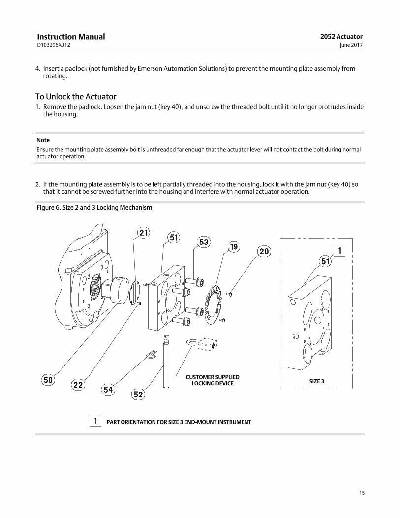
Figure 6. Size 2 and 3 Locking Mechanism
PART ORIENTATION FOR SIZE 3 END-MOUNT INSTRUMENT
CUSTOMER SUPPLIEDLOCKING DEVICE SIZE 3
Instruction ManualD103296X012
2052 ActuatorJune 2017
16
Installing the Size 2 and 3 Locking MechanismTo add the locking mechanism (figure 6) to an existing actuator, purchase the required kit from Emerson AutomationSolutions.
1. The actuator should be mounted to the valve body and both travel stops (key 23) properly positioned prior toinstalling the locking mechanism.
2. Ensure the actuator lever (key 14) is in the spring-fail position (against the up travel stop).
3. Assemble the lockout kit by positioning the locking shaft (key 50) within the center through-hole of the mountingplate (key 51), as shown in figure 6. Insert the locking pin (key 52) through the center pinhole of the mounting plateand through the pin hole in the locking shaft. Install the hairpin cotter pin (key 54) for retention.
4. If installing the lockout kit on an existing actuator, remove the travel indicator (key 21) and travel indicator scale(key 19) from the actuator by loosening the appropriate screws.
5. Position the lockout kit against the actuator outboard end. The locking shaft will insert and engage the lever endgeometry.
Size 2 actuator: The standard size 2 lockout kit orientation shown in figure 6 will accommodate the use ofwindow-mount and end-mount digital valve controllers, positioners, and accessories. This orientation requiresremoval of the locking pin in the direction of the bottom side of the actuator.
Size 3 actuator: For the window mounted DVC6200 digital valve controller, the size 3 lockout kit should be orientedsuch that locking pin removal is in the direction of the bottom side of the actuator. This mounting plate positionprovides necessary clearance with the integral supply pressure regulator. For the end-mount digital valve controller oraccessory option, the size 3 lockout kit should be oriented as shown in the inset picture of figure 6.
6. Loosely install the four flanged cap screws (key 53). Prior to tightening the fasteners, ensure the through-hole in themounting plate is centered around the outside diameter of the locking shaft (key 50). Rotate the assembly by handin the appropriate direction opposite of anticipated lever rotation to eliminate initial clearance among parts.
7. Tighten the cap screws (key 53) per the recommended torque values in table 6.
8. Install the travel indicator (key 21) and travel indicator scale (key 19) to the lockout parts as illustrated in figure 6.
WARNING
To avoid personal injury or property damage, ensure the travel indicator is installed correctly to coincide with the desiredactuator action. Refer to figure 3 for more information.
9. For normal actuator operation, remove the hairpin cotter pin (key 54) and locking pin (key 52) from the centerpinhole of the mounting plate and reinstall these parts in the second pinhole for storage.
Operating the Locking Mechanism (Size 2 & 3)
To Lock the Actuator1. With the actuator lever (key 14) against the up travel stop (spring-fail position), insert the locking pin (key 52)
through the center pinhole of the mounting plate and through the pin hole in the locking shaft. Install the hairpincotter pin (key 54) for retention.
2. Install the customer-supplied locking device to further prevent removal of the locking pin.
To Unlock the Actuator1. Remove the customer-supplied locking device.
2. Remove the hairpin cotter pin (key 54) and locking pin (key 52) from the center pinhole of the mounting plate andreinstall these parts in the second pinhole for storage.
Instruction ManualD103296X012
2052 ActuatorJune 2017
17
WARNING
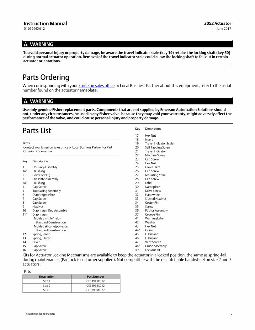
To avoid personal injury or property damage, be aware the travel indicator scale (key 19) retains the locking shaft (key 50)during normal actuator operation. Removal of the travel indicator scale could allow the locking shaft to fall out in certainactuator orientations.
Parts OrderingWhen corresponding with your Emerson sales office or Local Business Partner about this equipment, refer to the serialnumber found on the actuator nameplate.
WARNING
Use only genuine Fisher replacement parts. Components that are not supplied by Emerson Automation Solutions shouldnot, under any circumstances, be used in any Fisher valve, because they may void your warranty, might adversely affect theperformance of the valve, and could cause personal injury and property damage.
Parts List
Note
Contact your Emerson sales office or Local Business Partner for Part
Ordering information.
Key Description
1 Housing Assembly
1a* Bushing
2 Cover or Plug
3 End Plate Assembly
3a* Bushing
4 Cap Screw
5 Top Casing Assembly
6 Diaphragm Plate
7 Cap Screw
8 Cap Screw
9 Hex Nut
10 Diaphragm Rod Assembly
11* Diaphragm
Molded nitrile/nylon
Standard Construction
Molded silicone/polyester
Standard Construction
12 Spring, Inner
13 Spring, Outer
14 Lever
15 Cap Screw
16 Cap Screw
Key Description
17 Hex Nut
18 Insert
19 Travel Indicator Scale
20 Self Tapping Screw
21 Travel Indicator
22 Machine Screw
23 Cap Screw
24 Hex Nut
25 Cover Plate
26 Cap Screw
27 Mounting Yoke
28 Cap Screw
29 Label
30 Nameplate
31 Drive Screw
32 Handwheel
33 Slotted Hex Nut
34 Cotter Pin
35 Screw
36 Pusher Assembly
37 Groove Pin
41 Warning Label
42 Washer
43 Hex Nut
44* O‐Ring
45 Lubricant
46 Lubricant
47 Vent Screen
48* Guide Assembly
49 Lockout Kit
Kits for Actuator Locking Mechanisms are available to keep the actuator in a locked position, the same as spring-fail,during maintenance. (Padlock is customer supplied). Not compatible with the declutchable handwheel on size 2 and 3actuators.
KitsDescription Part Number
Size 1 GE51941X012
Size 2 GE52968X012
Size 3 GE52968X022
*Recommended spare parts
Instruction ManualD103296X012
2052 ActuatorJune 2017
18
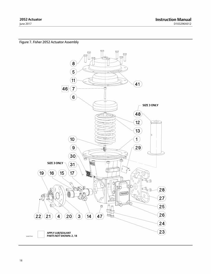
Figure 7. Fisher 2052 Actuator Assembly
GE42779-C
APPLY LUB/SEALANTPARTS NOT SHOWN: 2, 18
SIZE 3 ONLY
SIZE 3 ONLY
Instruction ManualD103296X012
2052 ActuatorJune 2017
19
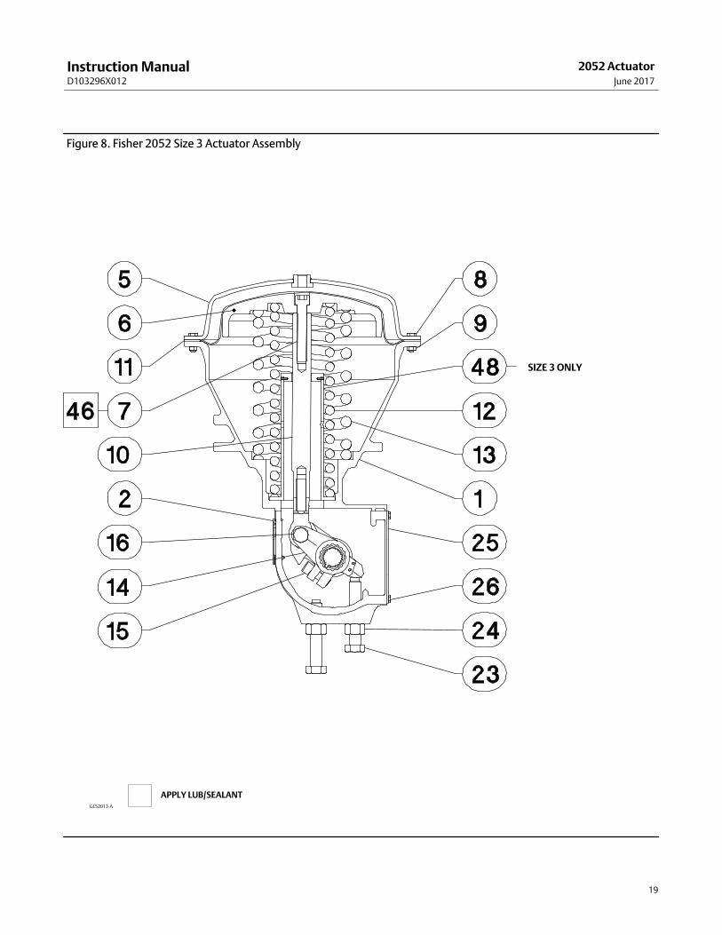
Figure 8. Fisher 2052 Size 3 Actuator Assembly
GE52013-A
APPLY LUB/SEALANT
SIZE 3 ONLY

Instruction ManualD103296X012
2052 ActuatorJune 2017
20
Figure 9. Fisher 2052 Size 1 Handwheel Assembly
GE33241_A
APPLY LUBRICANT
Emerson Automation Solutions Marshalltown, Iowa 50158 USASorocaba, 18087 BrazilCernay, 68700 FranceDubai, United Arab EmiratesSingapore 128461 Singapore
www.Fisher.com
The contents of this publication are presented for informational purposes only, and while every effort has been made to ensure their accuracy, they are notto be construed as warranties or guarantees, express or implied, regarding the products or services described herein or their use or applicability. All sales aregoverned by our terms and conditions, which are available upon request. We reserve the right to modify or improve the designs or specifications of suchproducts at any time without notice.
� 2009, 2017 Fisher Controls International LLC. All rights reserved.
Fisher, Control-Disk, and GO Switch are marks owned by one of the companies in the Emerson Automation Solutions business unit of Emerson Electric Co.Emerson Automation Solutions, Emerson, and the Emerson logo are trademarks and service marks of Emerson Electric Co. All other marks are the propertyof their respective owners.
Neither Emerson, Emerson Automation Solutions, nor any of their affiliated entities assumes responsibility for the selection, use or maintenanceof any product. Responsibility for proper selection, use, and maintenance of any product remains solely with the purchaser and end user.