Fisher 1051 and 1052 Style H and J Sizes 40, 60 and 70 ... · Fisher™ 1051 and 1052 Style H and...
40
www.Fisher.com Fisher ™ 1051 and 1052 Style H and J Sizes 40, 60 and 70 Rotary Actuators Contents Introduction 1 ................................. Scope of Manual 1 ............................. Description 2 ................................. Specifications 3 ............................... Educational Services 3 ......................... Principle of Operation 4 ........................ Installation 4 .................................. Actuator Mounting 5 .......................... Loading Connections 12 ........................ Adjustment 13 ................................. 1051 and 1052 Turnbuckle Adjustment 13 ........ 1052 Spring Adjustment 14 ..................... Initial Compression 14 ...................... Stroking Range 15 ......................... Maintenance 15 ................................ Disassembly 16 ............................... Assembly 18 .................................. Changing Actuator Mounting 22 .................. Changing Styles 22 ............................ Changing Positions 23 ......................... Top‐Mounted Handwheels and Adjustable Travel Stops 25 ....................... Handwheel and Travel Stop Operations 25 ........ Handwheel and Travel Stop Maintenance 26 ....... For Top‐Mounted Handwheels and Adjustable Up Travel Stops 27 .......................... For Adjustable Down Travel Stops 27 ............. Figure 1. Fisher 1051 Actuator with H Mounting Adaptation and 3610J Positioner W4252 Parts Ordering 28 ............................... Parts List 28 ................................... Introduction Scope of Manual This manual provides installation, adjustment, operation, maintenance, and parts ordering information for Fisher 1051 (sizes 40 and 60) and 1052 (sizes 40, 60, and 70) diaphragm rotary actuators with H and J mounting adaptations (see figures 1 and 2). Also, this instruction manual provides information for the optional top‐mounted handwheel, and both the optional up and down travel stops. Instructions for the control valve body, the positioner, accessories, and other sizes or constructions of this actuator are covered in separate manuals. Instruction Manual D100320X012 1051 and 1052 H & J Actuators June 2017
Transcript of Fisher 1051 and 1052 Style H and J Sizes 40, 60 and 70 ... · Fisher™ 1051 and 1052 Style H and...

www.Fisher.com
Fisher™ 1051 and 1052 Style H and JSizes 40, 60 and 70 Rotary Actuators
ContentsIntroduction 1. . . . . . . . . . . . . . . . . . . . . . . . . . . . . . . . .
Scope of Manual 1. . . . . . . . . . . . . . . . . . . . . . . . . . . . .Description 2. . . . . . . . . . . . . . . . . . . . . . . . . . . . . . . . .Specifications 3. . . . . . . . . . . . . . . . . . . . . . . . . . . . . . .Educational Services 3. . . . . . . . . . . . . . . . . . . . . . . . .Principle of Operation 4. . . . . . . . . . . . . . . . . . . . . . . .
Installation 4. . . . . . . . . . . . . . . . . . . . . . . . . . . . . . . . . .Actuator Mounting 5. . . . . . . . . . . . . . . . . . . . . . . . . .Loading Connections 12. . . . . . . . . . . . . . . . . . . . . . . .
Adjustment 13. . . . . . . . . . . . . . . . . . . . . . . . . . . . . . . . .1051 and 1052 Turnbuckle Adjustment 13. . . . . . . .1052 Spring Adjustment 14. . . . . . . . . . . . . . . . . . . . .
Initial Compression 14. . . . . . . . . . . . . . . . . . . . . .Stroking Range 15. . . . . . . . . . . . . . . . . . . . . . . . .
Maintenance 15. . . . . . . . . . . . . . . . . . . . . . . . . . . . . . . .Disassembly 16. . . . . . . . . . . . . . . . . . . . . . . . . . . . . . .Assembly 18. . . . . . . . . . . . . . . . . . . . . . . . . . . . . . . . . .
Changing Actuator Mounting 22. . . . . . . . . . . . . . . . . .Changing Styles 22. . . . . . . . . . . . . . . . . . . . . . . . . . . .Changing Positions 23. . . . . . . . . . . . . . . . . . . . . . . . .
Top‐Mounted Handwheels and Adjustable Travel Stops 25. . . . . . . . . . . . . . . . . . . . . . .
Handwheel and Travel Stop Operations 25. . . . . . . .Handwheel and Travel Stop Maintenance 26. . . . . . .For Top‐Mounted Handwheels and Adjustable
Up Travel Stops 27. . . . . . . . . . . . . . . . . . . . . . . . . .For Adjustable Down Travel Stops 27. . . . . . . . . . . . .
Figure 1. Fisher 1051 Actuator with H MountingAdaptation and 3610J Positioner
W4252
Parts Ordering 28. . . . . . . . . . . . . . . . . . . . . . . . . . . . . . .Parts List 28. . . . . . . . . . . . . . . . . . . . . . . . . . . . . . . . . . .
Introduction
Scope of ManualThis manual provides installation, adjustment, operation, maintenance, and parts ordering information for Fisher1051 (sizes 40 and 60) and 1052 (sizes 40, 60, and 70) diaphragm rotary actuators with H and J mounting adaptations(see figures 1 and 2). Also, this instruction manual provides information for the optional top‐mounted handwheel, andboth the optional up and down travel stops. Instructions for the control valve body, the positioner, accessories, andother sizes or constructions of this actuator are covered in separate manuals.
Instruction ManualD100320X012
1051 and 1052 H & J ActuatorsJune 2017

Instruction ManualD100320X012
1051 and 1052 H & J ActuatorsJune 2017
2
Table 1. Fisher 1051 and 1052 Actuator Specifications
Operation
Direct Acting: Increasing loading pressure extendsthe diaphragm rod out of the spring barrel
Service:
1051: For on‐off or throttling service with positioner
1052: For on‐off or throttling service with or without apositioner
Actuator Sizes
1051: 40, and 601052: 40, 60, and 70
Maximum Diaphragm Sizing Pressure(2)(3)
Size 40: 4.5 bar (65 psig)Size 60: 2.8 bar (40 psig)Size 70: 3.8 bar (55 psig)
Maximum Diaphragm Casing Pressure(2)(3)
Size 40: 5.2 bar (75 psig)Size 60: 3.4 bar (50 psig)Size 70: 4.5 bar (65 psig)
Maximum Valve Shaft Rotation
90, 75, or 60 deg with optional stops
Torque Limits (mm)(4)
Limited by maximum diaphragm sizing pressure ortables 2 and 3, whichever is less
Stroking Time
Dependent on actuator size, rotation, spring rate,initial spring compression, and supply pressure. Ifstroking time is critical, consult your Emerson salesoffice
Material Temperature Capabilities(3)
Nitrile Diaphragm or O‐Rings(1): -40 to 82�C (-40 to 180�F)
Silicone Diaphragm: -40 to 149�C (-40 to 300�F)
Travel Indication
Graduated disc and pointer combination located onactuator end of valve shaft
Pressure Connections
1/4 NPT internal
Mounting Positions
See figure 10
Approximate Weights
See table 8
Additional Specifications
For casing pressure ranges and for materialidentification of the parts, see the Parts List
1. Nitrile O‐rings are used in optional top‐mounted handwheel, adjustable down travel stop, and adjustable up travel stop assemblies.2. Use this value to determine the maximum torque output allowed.3. The pressure / temperature limits in this manual and any applicable standard or code limitation for valve should not be exceeded.4. Exceeding any torque requirements could damage the actuator and impair safe operation.
Do not install, operate, or maintain a 1051 or 1052 actuator without being fully trained and qualified in valve, actuator,and accessory installation, operation, and maintenance. To avoid personal injury or property damage, it is importantto carefully read, understand, and follow all the contents of this manual, including all safety cautions and warnings. Ifyou have any questions about these instructions, contact your Emerson sales office or Local Business Partner beforeproceeding.
Description1051 and 1052 diaphragm rotary actuators are pneumatic spring‐return actuators for use with rotary‐control valvesand other equipment. The 1051 actuator can be used for on‐off service, or it can be used for throttling service whenequipped with a valve positioner. The 1052 actuator can be used for on‐off service, or it can be used for throttlingservice when equipped with or without a valve positioner. The 1052 actuator spring is adjustable.
The H mounting adaptation permits the actuator to be used with equipment other than Fisher valve bodies. Themounting brackets and couplings for rotary actuation are user‐provided. This mounting adaptation includes aflat‐surface mounting plate that is drilled and tapped for attaching the user‐provided bracket. Cap screws for attachingthe bracket are provided. H mounting also includes an output shaft (with milled flats) to provide the Double D rotaryoutput either directly or through a user‐provided coupling. Output shaft diameters and torque limits are listed in table2. Dimensional information for the mounting plate and output shaft are shown in figures 4, 5, and 6.

Instruction ManualD100320X012
1051 and 1052 H & J ActuatorsJune 2017
3
Figure 2. Fisher 1052 Actuator with J Mounting Adaptation
W4139‐1
The J mounting adaptation permits the actuator to be used for rotary actuation of Fisher keyed‐shaft butterfly valvebodies and other keyed‐shaft equipment. This mounting adaptation uses the standard butterfly valve mountingbracket and provides an output shaft with an attached coupling for keyed equipment shafts. Coupling sizes and torquelimits are listed in table 3. Dimensional information for the mounting bracket and stub shaft coupling is shown infigures 4, 5, and 7.
Additionally, a top‐mounted handwheel can be applied for infrequent service as a manual handwheel actuator. Formore frequent manual operation, a side‐mounted handwheel actuator is available. Also, an adjustable up travel stopcan be added to limit the actuator stroke in the upward direction, or an adjustable down travel stop can be added tolimit actuator stroke in the downward direction.
SpecificationsSpecifications are shown in table 1 for 1051 and 1052 actuators. Specifications for a given 1051 or 1052 actuator as itoriginally comes from the factory are stamped on a nameplate attached to the actuator.
Educational ServicesFor information on available courses for 1051 and 1052 Style H and J actuators, as well as a variety of other products,contact:
Emerson Automation SolutionsEducational Services - RegistrationPhone: 1-641-754-3771 or 1-800-338-8158E-mail: [email protected]/fishervalvetraining

Instruction ManualD100320X012
1051 and 1052 H & J ActuatorsJune 2017
4
Table 2. Output Shaft Diameters and Torque Limits for Actuators With H Mounting
ACTUATOR SIZEOUTPUT SHAFT DIAMETER TORQUE LIMIT FOR H MOUNTING
mm Inches N�m Inch‐Pounds
4022.228.638.1
7/81‐1/81‐1/2
240468
1110
212041409815
6028.638.1
1‐1/81‐1/2
4681210
414010,680
70(1) 38.1 1‐1/2 1210 10,680
1. 1052 actuator only.
Table 3. Acceptable Shaft Diameters and Torque Limits for Actuators With J Mounting
ACTUATOR SIZECOUPLING AVAILABILITY BY KEYED SHAFT DIAMETER TORQUE LIMIT FOR J MOUNTING
mm Inches N�m Inch‐Pounds
40
9.512.715.919.125.4
3/81/25/83/4
1
5269
114207468
460610
101018304140
60
19.125.431.838.150.8
3/41
1‐1/41‐1/2
2
207468
103013602650
183041409110
12,00023,430
70(1)31.838.150.8
1‐1/41‐1/22(2)
103013602650
911012,00023,430
1. 1052 actuator only.2. Coupling supplied for mating with either 44.5 or 50.8 mm (1‐3/4 or 2‐inch) keyed shaft.
Principle of OperationThe diaphragm rod moves down as loading pressure is increased on top of the diaphragm. As the loading pressure isdecreased, the spring forces the diaphragm rod upward.
The spring and diaphragm have been selected to meet the requirements of the application and, in service, theactuator should produce full travel of the valve or other operated equipment with the diaphragm pressure as indicatedon the nameplate.
Consult the separate positioner instruction manual for actuator principle of operation with positioner.
Installation
WARNING
Always wear protective gloves, clothing, and eyewear when performing any maintenance operations to avoid personalinjury.
To avoid personal injury or property damage caused by bursting of pressure retaining parts, be certain the serviceconditions do not exceed the limits given in table 1. Use pressure limiting or pressure relieving devices to prevent thediaphragm sizing pressure from exceeding the maximum allowable diaphragm sizing pressure.
Check with your process or safety engineer for any additional measures that must be taken to protect against processmedia.
If installing into an existing application, also refer to the WARNING at the beginning of the Maintenance section in thisinstruction manual.

Instruction ManualD100320X012
1051 and 1052 H & J ActuatorsJune 2017
5
WARNING
To avoid personal injury or parts damage, do not use an operating pressure that exceeds the Maximum Diaphragm CasingPressure (table 1) or produces a torque greater than the Maximum Allowable Valve Shaft Torque (see Catalog 14). Usepressure‐limiting or pressure‐relieving devices to prevent the diaphragm casing pressure from exceeding its limit.
Figure 3. Top Mounted Handwheel
ACTUATOR SIZEHC JC
mm Inch mm Inch
40 281 11.06 356 14.00
60 359 14.12 432 17.00
70(1) 335 13.62 356 14.00
1. Size 70 available in 1052 only.
TOP-MOUNTED HANDWHEEL19A1465-B
1/4 NPT
HC
JC (DIA)
E
Actuator MountingUse the following steps to connect the actuator to a valve body or other equipment. Unless otherwise specified, keynumbers are shown in figures 12 and 13. Mounting dimensions are shown in figures 4, 5, 6, and 7.
Note
For an actuator with an H mounting adaptation and a 22.2 through 38.1 mm (7/8 through 1‐1/2 inch) output shaft, finddimensions and center of gravity information in figures 3, 4, 5, 6, and 9, and approximate weights in table 8. This information isrequired for proper fabrication of the user‐provided bracket and coupling.
1. For an actuator with an H mounting adaptation, attach an appropriate mounting bracket (not provided) to themounting plate (key 22) with the cap screws (key 78). See figures 4, 5, and 6 for mounting dimensions on themounting plate. Tighten the cap screws to the bolt torques listed in table 4.
2. Consult figure 10 for available mounting styles and positions. The actuator is normally positioned vertically with thevalve body or other equipment in a horizontal pipeline.

Instruction ManualD100320X012
1051 and 1052 H & J ActuatorsJune 2017
6
Note
If the milled flats or the coupling on the end of the actuator output shaft (key 87) are oriented such that the output shaft cannotaccommodate the operated equipment shaft, refer to the Changing Positions portion of the Changing Actuator Mounting section.This procedure describes how the output shaft can be repositioned to accommodate the operated equipment shaft.
3. If using an actuator with a J mounting adaptation, note that the valve shaft coupling (key 90) is furnished with twokeyways lettered A and B as shown in figure 8 and 12 (letters C and D on the coupling are not used and can bedisregarded). Align the appropriate keyway with the keyway in the operated equipment shaft. If using a Fisherbutterfly valve, align the appropriate keyway on the coupling with the valve shaft keyway indicated in table 9. Theninstall the woodruff key (key 91) in the shaft keyseat, and slide the coupling onto the shaft. It is helpful to apply alight coat of grease to the inside of the coupling before sliding it onto the shaft.
4. For an actuator with an H mounting adaptation, slide the actuator (with the user‐provided mounting bracketattached) into the user‐provided coupling on the operated shaft. Then, secure the actuator to the operatedequipment in the desired mounting position with the appropriate fasteners, such as mounting cap screws. Seefigures 4, 5 and 6 for output shaft dimensions.
5. For an actuator with a J mounting adaptation, secure the mounting bracket (key 22) to the valve body with the capscrews (key 78, not shown). Tighten the cap screws to the bolt torques in table 4. For 31.8 and 38.1 mm (1‐1/4 and1‐1/2 inch) valve shafts, also place the two spacers (key 92, not shown) between the mounting bracket and valvebody during this step.
6. For an actuator with a J mounting adaptation and a 50.8 mm (2‐inch) output shaft (key 87, figure 14), note that thevalve shaft coupling (key 90, figure 14) is furnished with two keyways lettered A and B as shown in figure 8 (letters Cand D on the coupling are not used and can be disregarded). Align the appropriate keyway with the keyway in theoperated equipment shaft. Then, install the woodruff key (key 91, not shown in figure 14) in the shaft keyseat, andslide the coupling onto the shaft using the appropriate coupling keyway (see table 9 and figure 8). It is helpful toapply a light coat of grease to the inside of the coupling before sliding it onto the shaft. Secure the actuator(user‐provided mounting bracket) to the operated equipment in the desired mounting position with theappropriate fasteners, such as mounting cap screws.
7. Follow the instructions given in the Turnbuckle Adjustment section before proceeding to the Loading Connectionportion of this section.
Table 4. Key 78 Cap Screw Torque ValuesSTYLE H MOUNTING
Actuator SizeValve Shaft Diameter Bolt Size Bolt Torque Key 78
Part Numbermm Inch Inch N•m lbf•ft
40 22.2 7/8 5/16 22.6 16.7 1C5958X0042
40 28.6 1-1/8 3/8 39 29 1A353124052
60 28.6 1-1/8 3/8 39 29 1A353124052
40 38.1 1-1/2 1/2 92 68 1A582324052
60, 70 38.1 1-1/2 1/2 92 68 1A582324052
STYLE J MOUNTING - FLAT PLATE MOUNTING
60, 70 44.5 1-3/4 1/2 92 68 1A582324052
60, 70 50.8 2 1/2 92 68 1A582324052
STYLE J MOUNTING - FISHER 7600, 9100, 9500 WITH KEYED SHAFT
40 9.5 3/8 3/8 39 29 1A341824052
40 12.7 1/2 3/8 39 29 1A341824052
40 15.9 5/8 3/8 39 29 1A341824052
40 19.1 3/4 3/8 39 29 1A341824052
60 19.1 3/4 3/8 39 29 1A341824052
40 25.4 1 3/8 39 29 1A341824052
60 25.4 1 3/8 39 29 1A341824052
60, 70 31.8 1-1/4 5/8 163 120 1P1477X0012
60, 70 38.1 1-1/2 5/8 163 120 1P1477X0012

Instruction ManualD100320X012
1051 and 1052 H & J ActuatorsJune 2017
7
Table 5. Style H or J Mounting Dimensions
ACTUATOR SIZE CE
F H P Y1051 1052
mm
40 333 505 607 54 114 175 73
60 473 749 876 64 121 186 76
70(1) 536 - - - 849 64 121 186 76
Inch
40 13.12 19.88 23.88 2.12 4.50 6.88 2.88
60 18.62 29.50 34.50 2.50 4.75 7.31 3.00
70(1) 21.12 - - - 33.44 2.50 4.75 7.31 3.00
1. Size 70 available in 1052 only.
Figure 4. Fisher 1051 Mounting Dimensions (refer to table 5)1/4 NPT
19A1465‐C
C0577‐3
NOTE: SEE PARTS LIST FOR WOODRUFF KEY NUMBERS1
1
1/4 NPT C (DIA)
E E
H
Y F
P
H
Y
1051 1051 STYLE H MOUNTING ADAPTATION
WOODRUFFKEY
1051 STYLE JMOUNTING ADAPTATION
19A1459‐B
19A1459‐B

Instruction ManualD100320X012
1051 and 1052 H & J ActuatorsJune 2017
8
Figure 5. Fisher 1052 Mounting Dimensions (refer to table 5)
C0676‐3
NOTE: SEE PARTS LIST FOR WOODRUFF KEY NUMBERS1
19A1467-E /
1
1/4 NPT
C (DIA)
E
H
Y
F
P
1052
WOODRUFFKEY
1052 STYLE J ADAPTATION9.5 THRU 38.1 mm (3/8 THRU 1‐1/2‐INCH) OUTPUT SHAFTS
19A1461‐D
19A1461-G
1/4 NPT
E
H
Y
1052 STYLE J MOUNTING ADAPTATIONFOR 44.5 AND 50.8 mm (1‐3/4 AND 2‐INCH)
KEYED EQUIPMENT SHAFT
19A1461‐D
1052 STYLE H ADAPTATION12.7 THRU 38.1 mm (1/2 THRU 1‐1/2‐INCH) OUTPUT SHAFTS
E
H
Y
S (DIA)
M
K
N
S�
L
V
K

Instruction ManualD100320X012
1051 and 1052 H & J ActuatorsJune 2017
9
Table 6. Style H Mounting Dimensions
ACTUATORSIZE 1051
ACTUATORSIZE 1052
SACTUATOR
OUTPUT SHAFTDIAMETER
V L K(1) T UW
mm Inch mm Inch mm Inch mm Inch mm Inch mm Inch
40 40 22.2 7/8 26.2 1.03 19.1 0.7515.7515.62
0.6200.615
57.2 2.25 28.4 1.125/16‐18
UNC
40 & 60
40 & 60 28.6 1‐1/8 26.2 1.03 19.1 0.7522.1021.97
0.8700.865
76.2 3.00 38.1 1.503/8‐16
UNC
40, 60 & 70 38.1 1‐1/2 28.4 1.50 28.4 1.1228.4528.32
1.1201.115
88.9 3.50 44.5 1.751/2‐13
UNC
1. Tolerance for the K dimension is indicated by showing maximum and minimum dimensions.
Figure 6. Fisher 1051 and 1052 Style H Mounting Dimensions (refer to table 6)
22.2 THRU 38.1 mm(7/8 THRU 1‐1/2 INCH)OUTPUT SHAFTS WITH
STYLE H MOUNTING
22.2 THRU 38.1 mm(7/8 THRU 1‐1/2 INCH)OUTPUT SHAFTS WITH
STYLE H MOUNTING
S (DIA)
K
L
V
T
U
W (DIA)19A1461-DA4997
19A1459-B
A3254-1

Instruction ManualD100320X012
1051 and 1052 H & J ActuatorsJune 2017
10
Table 7. Style J Mounting Dimensions
ACTUATORSIZE 1051
& 1052
VALVE SHAFTDIAMETER
COUPLING(1)
INNERDIAMETER
V L(2) K T U W
mm Inch mm Inch mm Inch mm Inch mm Inch mm Inch mm Inch mm Inch
40
9.5 3/89.539.58
0.3750.377
137 5.38 39.6 1.56 15.7 0.62 117 4.62 ‐ ‐ ‐ ‐ ‐ ‐ 11.2 0.44
12.7 1/212.7012.75
0.5000.502
137 5.38 39.6 1.56 15.7 0.62 117 4.62 ‐ ‐ ‐ ‐ ‐ ‐ 11.2 0.44
15.9 5/815.9015.95
0.6260.628
160 6.31 49.3 1.94 25.4 1.00 146 5.75 31.8 1.25 11.2 0.44
40 & 60
19.1 3/419.0519.10
0.7500.752
160 6.31 47.8 1.88 20.6 0.81 146 5.75 31.8 1.25 11.2 0.44
25.4 125.4325.48
1.00101.0025
160 6.31 47.8 1.88 17.5 0.69 146 5.75 31.8 1.25 11.2 0.44
60 & 70(3)
31.8 1‐1/431.7531.80
1.2501.252
148 5.81 68.3 2.69 30.2 1.19 210 8.25 50.8 2.00 17.5 0.69
38.1 1‐1/238.1338.18
1.5011.503
148 5.81 68.3 2.69 23.9 0.94 210 8.25 50.8 2.00 17.5 0.69
60 & 70(3)
44.5 & 50.8
1‐3/4 & 2
44.4544.50
1.7501.752
123 4.84 69.9 2.75 ‐ ‐ ‐ ‐ ‐ ‐ 88.9 3.50 44.5 1.751/2‐13UNC(4)
1/2‐13UNC(5)
50.8 250.8350.90
2.0012.004
123 4.84 69.9 2.75 ‐ ‐ ‐ ‐ ‐ ‐ 88.9 3.50 44.5 1.751/2‐13UNC(4)
1/2‐13UNC(5)
1. Tolerance for the Coupling Inner diameter is indicated by showing maximum and minimum dimensions.2. The L dimension is the matchline to the end of the actuator shaft.3. Size 70 is only available for the 1052.4. 25.4 mm deep.5. 1 inch deep.
Figure 7. Fisher 1051 and 1052 Style J Mounting Dimensions (refer to table 7)
Y
S�
L
V
19A1461‐G
STYLE J MOUNTING44.5 and 50.8 mm (1‐3/4 and 2‐INCH)
44.5 AND 50.8 mm (1‐3/4 AND 2‐INCH)KEYED EQUIPMENT SHAFTS WITH
STYLE J MOUNTING
STYLE J MOUNTING9.5 through 38.1 mm
(3/8 through 1-1/2 INCH)
19A1465‐BA4996 V
K
L
WOODRUFFKEY
MOUNTING YOKE(KEY 22)
15.9 THROUGH 38.1 mm(5/8 THROUGH 1-1/2 INCH)
VALVE SHAFTS WITH STYLE J MOUNTING
9.5 AND 12.7 mm(3/8 AND 1/2 INCH) VALVE SHAFTS
WITH STYLE J MOUNTING
COUPLING INNERDIAMETER COUPLING INNER
DIAMETER
U
U
T
TT
WW (DIA)W (DIA)19A1465-B 19A1465-B
19A1459-B
A3254-1A3254-1
COUPLING INNERDIAMETER

Instruction ManualD100320X012
1051 and 1052 H & J ActuatorsJune 2017
11
Table 8. Approximate Actuator Weights
SIZE1051 1052 TOP‐MOUNTED HANDWHEEL
Kg Lb Kg Lb Kg Lb
406070
4389-�-�-
94197-�-�-
4592
123
99203272
7.311
21.3
162447
Table 9. Keyway Alignment Information(1)
DESIREDACTUATOR
ACTION
DESIRED SHAFTROTATION,
DEGREES
ACTUATORMOUNTING
POSITION
COUPLINGKEYWAY TO
USE(3)
VALVE SHAFT KEYWAY TO USE FOR FISHTAIL™ DISC VALVE BODIES(2)
(SEE FIGURE 10)
Clockwise toClose Valve Action(4)
Counterclockwise toClose Valve Action(4)
Flow Left toRight(4)
Flow Right toLeft(4)
Flow Left toRight(4)
Flow Right toLeft(4)
Push Down toOpen (PDTO)
60 or 90
1 B Nose Tail Tail Nose
2 A Tail Nose Nose Tail
3 B Tail Nose Nose Tail
4 A Nose Tail Tail Nose
Push Down toClose (PDTC)
60(5) or 90
1 A Tail Nose Tail Nose
2 B Tail Nose Tail Nose
3 A Nose Tail Nose Tail
4 B Nose Tail Nose Tail
1. For actuators with J mounting.2. For conventional disc valve bodies, use either valve shaft keyway.3. See figure 10 for reference coupling orientation to use with this table.4. When viewed from actuator side of valve body.5. For 60‐degree rotation with PDTC action, the coupling and actuator output shaft assembly will be offset 30 degrees clockwise (for actuator housing construction style B) or counterclockwise(for actuator housing construction Style A) in the lever when viewed from the splined end of the actuator shaft. 30 degrees is one spline tooth for 9.5, 12.7, and 15.9 mm (3/8, 1/2, and5/8‐inch) valve shafts and two spline teeth for 19.1 through 38.1 mm (3/4 through 1‐1/2 inch) valve shafts.
Figure 8. Valve Shaft Coupling
EXPLODED VIEW OF VALVE SHAFTAND COUPLING
REFERENCE COUPLING ORIENTATIONFOR TABLE 9
NOTE: FOR USE WITH J MOUNTING ADAPTATION (UP TO 50.8 mm (2‐INCH) KEYED SHAFT DIAMETERS.1
1
A3253‐1
FULL KEYWAYLOCATED ONNOSE AND TAILSIDE OF VALVE SHAFT
VALVE SHAFT
COUPLING
PARTIAL KEYWAYFOR DETERMININGDISC POSITION
USE APPROPRIATE LETTEREDKEYWAY AS INDICATED INTABLE 9
USE APPROPRIATEVALVE SHAFTKEYWAY ASINDICATEDIN TABLE 9
KEYWAY A KEYWAY BABOVEKEYWAY A
19B1465‐B

Instruction ManualD100320X012
1051 and 1052 H & J ActuatorsJune 2017
12
Figure 9. Center of Gravity Dimensions
ACTUATOR TYPE ACTUATOR SIZEX Y
mm Inch mm Inch
105140 15 0.6 191 7.5
60 10 0.4 361 14.2
1052
40 15 0.6 241 9.5
60 10 0.4 432 17.0
70 23 0.9 488 19.2
Y
X19A1459-BA3255
Loading Connection1. Connect the loading pressure piping to the pressure connection in the top of the diaphragm casing.
For size 40 through 60 actuators, run either NPS 1/4 pipe or 3/8‐inch tubing between the NPT 1/4 pressure connectionand the positioner or automatic controller.
For size 70 actuators, run either pipe or tubing between the pressure connection and the positioner or automaticcontroller. If necessary, remove the 1/4‐inch bushing in the pressure connection to increase connection size.
2. Keep the length of pipe or tubing as short as possible to avoid transmission lag in the control signal. If an accessory(such as a volume booster or a positioner) is used, be sure that the accessory is properly connected to the actuator.If a positioner is part of the assembly, the pressure connection to the actuator will normally be made at the factory.
3. When the actuator is completely installed and connected to the instrument, check for correct action (air‐to‐open orair‐to‐close) to match the controlling instrument. For successful operation, the actuator stem and operating shaftmust move freely in response to the loading pressure change on the diaphragm.

Instruction ManualD100320X012
1051 and 1052 H & J ActuatorsJune 2017
13
Adjustment
WARNING
Before performing any adjustment steps, follow the steps in the WARNING at the beginning of the Maintenance section.
1051 and 1052 Turnbuckle AdjustmentCorrect turnbuckle adjustment ensures that the valve body or other operated equipment is correctly closed when theactuator is against its travel stops. The turnbuckle adjustment is the only adjustment necessary on the 1051 actuator.Key numbers used in this procedure are shown in figure 12 for 1051 actuators and in figure 13 for 1052 actuators.
For accurate adjustment, remove the valve body or other operated equipment from the pipeline.
A regulated air supply will be required to stroke the actuator. Consult table 10 for the sizes of the three open endwrenches required for this procedure.
1. Remove the access plate (key 59). Also remove the machine screws (key 60), if present.
Note
For the most accurate adjustment of the actuator, do not remove the cover (key 33) during this procedure.
2. Loosen the lower locknut (key 16).
Table 10. Wrench Sizes Required for Turnbuckle Adjustment, InchesActuator Size Turnbuckle (Key 57) Lower Locknut (Key 16) Upper Locknut (Key 58)
1051 & 10524060
1‐1/81‐5/16
3/415/16
1‐1/81‐5/16
1052 70 1‐5/16 1‐1/8 1‐5/16
3. Make sure the actuator housing (key 20) is clear of any tools or other instruments that could obstruct the actuatorstroke path. Pressure the diaphragm casing enough to stroke the actuator down so that the left‐hand threadedupper locknut (key 58) is accessible through the access opening. Loosen the locknut.
4. Use one of the following:
a. For push‐down‐to‐close action—Slowly stroke the actuator to the down travel stop. Consult the appropriateinstruction manual for determining the closed position of the valve body or other operated equipment. Adjustthe turnbuckle (key 57) until the closed position is reached. Lock this adjustment with the left‐hand threadedlocknut (key 58). Stroke the actuator to the mid‐travel position, and tighten the locknut (key 16). Tighten eachlocknut to the appropriate torque value listed in table 11.
WARNING
Exceeding any torque requirements could damage the actuator and impair safe operation.

Instruction ManualD100320X012
1051 and 1052 H & J ActuatorsJune 2017
14
b. For push‐down‐to‐open action—Consult the appropriate instruction manual for determining the closed positionof the valve or other operated equipment. Release all pressure from the diaphragm casing, making sure thediaphragm is against its up travel stop. Be sure that the optional handwheel is adjusted to its topmost position sothat the closed position of the actuator and valve body or other operated equipment can be reachedsimultaneously. Check the position of the valve body or other operated equipment with respect to its properlyclosed position. Stroke the actuator so the turnbuckle (key 57) is accessible through the access opening. Adjustthe linkage. Release pressure to the actuator, and check the new adjustment. Continue this procedure until theoperated equipment is in the closed position when the actuator is resting on its up travel stop. Tighten locknut(key 16). Stroke the actuator, and tighten the left‐hand threaded locknut (key 58). Tighten each locknut to theappropriate torque value listed in table 11.
WARNING
Exceeding any torque requirements could damage the actuator and impair safe operation.
5. Replace the access plate (key 59). Also, replace the machine screws (key 60), if present.
6. Loosen the self‐tapping screws (key 38), and adjust the travel indicator (key 37). Retighten the self‐tapping screws.
1052 Spring Adjustment
Initial Compression
The 1052 nameplate specifies a spring set, which is the initial compression adjusted into the actuator spring, Initialcompression is the casing pressure at which the diaphragm and diaphragm rod begin to move away from the up travelstop with the actuator disconnected from the valve body or other operated equipment. (With the actuator connectedand pressure applied to the valve body or other operated equipment, a higher casing pressure will be required to startactuator travel). The initial compression was selected (based upon the service conditions specified when the actuatorwas ordered) so that when the actuator and valve body or other operated equipment are in service, the operatedequipment will close properly and full travel will be obtained within a diaphragm casing pressure range of 0 to 1.2, 0 to2.3, 0 to 2.8 or 0 to 3.8 bar (0 to 18, 0 to 33, 0 to 40, or 0 to 55 psig) depending on specific actuator size andconstruction.
If the actuator has been disassembled or if the spring adjustment was changed, and it is desired to match the initialcompression stated on the nameplate, make sure the rod end bearing (key 17, figure 13) has been disconnected fromthe lever (key 27, figure 13). Adjust the spring so that the diaphragm rod just starts to travel at the spring set pressurespecified on the nameplate. Be sure the rod end bearing does not hit the lever as the diaphragm and diaphragm rodmove away from the up travel stop.
To adjust the spring, insert a round rod into one of the slots in the lower bearing seat (key 73, figure 13). Slot diameteris 9.5 mm (3/8‐inch) for size 40 actuators, 15.9 mm (5/8‐inch) for size 60 actuators, and 19.1 mm (3/4‐inch) for size 70actuators.
Rotate the bearing seat to move it toward the casings (keys 1 and 2, figure 13) to increase initial compression or awayfrom the casings to decrease initial compression.

Instruction ManualD100320X012
1051 and 1052 H & J ActuatorsJune 2017
15
Table 11. Recommended Bolting Torques(1)
KEY NUMBER
ACTUATOR SIZE
40 60 70
N�m lbf�ft N�m lbf�ft N�m lbf�ft
6 27 20 27 20 27 20
7 & 8 41 30 41 30 102 75
9 34 25 102 75 102 75
16 34 25 61 45 102 75
18 81 60 163 120 271 200
21 23 17 68 50 68 50
23 34 25 81 60 81 60
28 81 60 163 120 271 200
34 34 25 81 60 81 60
40 9 7 9 7 9 7
54 handwheel 34 25 34 25 34 25
54 down stop 27 20 66 49 69 51
58 102 75 163 120 163 120
141 41 30 41 30 81 60
1. Exceeding any torque requirements could damage the actuator and impair safe operation.
Stroking Range
The initial spring set listed on the nameplate has been determined to be the optimum setting, and it is notrecommended to make spring adjustments that will cause this value to change or be exceeded. Forpush‐down‐to‐open (PDTO) action, the initial spring set is normally the maximum allowable to provide the maximumspring closing force. Any increase of this setting could over‐stress the spring at full travel. For push‐down‐to‐close(PDTC) action, the initial spring set has been determined to be the optimum balance between the air to close and thespring to open breakout torque.
If the 1052 actuator is to be changed from one action to another (i.e., from PDTC to PDTO), first refer to the initialspring compression values listed in the table for keys 11 and 13 in the Parts List section. Then adjust the unit accordingto the procedures in the Initial Compression portion of this section.
MaintenanceActuator parts are subject to normal wear and must be inspected and replaced as necessary. The frequency ofinspection and replacement depends upon the severity of service conditions. Instructions are given below fordisassembly and assembly of parts. Key numbers referenced in the following steps are shown in figure 12 for 1051actuators and in figure 13 for 1052 actuators unless otherwise specified.
WARNING
Avoid personal injury or property damage from sudden release of process pressure or uncontrolled movement of parts.Before performing any maintenance operations:
� Do not remove the actuator from the valve while the valve is still pressurized.
� Always wear protective gloves, clothing, and eyewear when performing any maintenance operations to avoid personalinjury.
� Disconnect any operating lines providing air pressure, electric power, or a control signal to the actuator. Be sure theactuator cannot suddenly open or close the valve.

Instruction ManualD100320X012
1051 and 1052 H & J ActuatorsJune 2017
16
� Use bypass valves or completely shut off the process to isolate the valve from process pressure. Relieve process pressurefrom both sides of the valve. Drain the process media from both sides of the valve.
� Vent the power actuator loading pressure and relieve any actuator spring precompression.
� Use lock‐out procedures to be sure that the above measures stay in effect while you work on the equipment.
� The valve packing box may contain process fluids that are pressurized, even when the valve has been removed from thepipeline. Process fluids may spray out under pressure when removing the packing hardware or packing rings, or whenloosening the packing box pipe plug.
� Check with your process or safety engineer for any additional measures that must be taken to protect against processmedia.
DisassemblyThe following procedure describes how the actuator can be completely disassembled. When inspection or repairs arerequired, perform only those steps necessary to accomplish the procedure. Do not under ordinary circumstancesremove the cap screws (keys 7, 8, and 21).
CAUTION
Cap screw (key 18) must be disengaged from the lever (key 27) before removing the diaphragm casing (key 1). Failure to doso will allow the spring precompression to rotate the valve body or other operated equipment beyond its fully open orclosed position. This could cause damage to the operated equipment.
1. Bypass the valve or other operated equipment. Relieve all actuator loading pressure, and remove the tubing or pipefrom the top of the actuator.
2. Remove the positioner, if one is used.
3. Mark the orientation of the travel indicator (key 37) with respect to the travel indicator scale (key 35). Then,unscrew the cap screws and washers (keys 34 and 63), and remove the cover (key 33).
4. Remove the retaining ring (key 30), and then remove the hub (key 29) from the cover.
5. Check the condition of the bearing (key 31). If replacement of the bearing is necessary, the travel indicator scale(key 35) must first be removed by removing the self‐tapping screws (key 36). Mark the orientation of the travelindicator scale on the cover before removing it.
CAUTION
When removing the actuator from the valve body, do not use a hammer or similar tool to drive the lever (key 27) oractuator off the output shaft (key 87). Driving the lever or actuator could damage operated equipment. For valves, drivingthe lever (key 27) could move the valve disc and bearings away from the centered position causing subsequent damage tovalve parts.
If necessary, use a wheel puller to remove the lever. It is permissible to tap the wheel puller screw lightly to loosen thelever, but hitting the screw with excessive force could also damage operated parts or disrupt the centered position of avalve disc or other equipment.
6. For an actuator with an H mounting adaptation and a 22.2 through 38.1 mm (7/8 through 1‐1/2 inch) output shaft,unscrew the cap screws (key 78) and remove the actuator from the operated equipment. Mark the orientation ofthe lever (key 27) with respect to the output shaft (key 87). This marking is used during reassembly to allow forproper lever/output shaft positioning.

Instruction ManualD100320X012
1051 and 1052 H & J ActuatorsJune 2017
17
Then, loosen the cap screw (key 28) so that the output shaft is free to slide off the lever. With the lever and outputshaft properly marked, unscrew the cap screws (key 23) and remove the mounting plate (key 22) and output shaft (key87) assembly from the actuator housing (key 20). If necessary, remove the retaining ring (key 88) and separate theoutput shaft from the mounting plate.
7. For an actuator with a J mounting adaptation (see figures 12 and 13) with a 50.8 mm (2‐inch) output shaft (seefigure 14) and proceed as follows:
a. Remove the cap screws (key 78, not shown in figures 12 and 13) and remove the actuator from the operatedequipment. For an actuator with J mounting and a 31.8 or 38.1 mm (1‐1/4 or 1‐1/2 inch) valve shaft diameter,two spacers (key 92, not shown in figures 12 and 13) are also removed with the cap screws (key 78).
b. When separating the output shaft (key 87) and coupling (key 90) from the operated shaft, remember to removethe woodruff key (key 91, not shown in figure 14) from the operated shaft keyway.
c. Mark the orientation of the lever (key 27, figures 12 and 13) with respect to the output shaft (key 87). Thismarking is used during reassembly to allow for proper lever/output shaft positioning,
d. Loosen the cap screw (key 28, figures 12 and 13) so that the output shaft is free to slide off the lever.
e. With the lever and output shaft properly marked, unscrew the cap screws (key 23) and remove either themounting bracket (key 22, figures 12 and 13 for J mounting) or the mounting plate (key 22, figure 14 for Hmounting) plus the attached output shaft (key 87) from the actuator housing (key 20).
f. If necessary, remove the retaining ring (key 88) and slide the mounting bracket or mounting plate off the outputshaft.
8. Check the bearing (key 67) in the mounting bracket or mounting plate (key 22). Press out and replace the bearing ifnecessary.
9. Heat the hex nut (key 19) to 177�C (350�F) long enough for the thread‐locking adhesive (high strength) (key 77) tolose its holding strength. Then, remove the cap screw and hex nut (keys 18 and 19), and remove the lever (key 27)from the housing.
10. Rotate the handwheel (if one is used) counter‐clockwise until the handwheel is not compressing the spring (key 11).
WARNING
To avoid personal injury from precompressed spring force suddenly thrusting the upper diaphragm casing (key 1) awayfrom the actuator, relieve 1052 spring compression, or carefully remove 1051 casing cap screws by following theinstructions presented in the next two steps before proceeding further.
11. To relieve 1052 spring compression, insert a round rod into one of the slots in the lower bearing seat (key 73). Slotdiameter is 9.5 mm (3/8 inch) for size 40 actuators, 15.9 mm (5/8 inch) for size 60 actuators, and 19.1 mm (3/4inch) for size 70 actuators. Use the rod to rotate the lower bearing seat, and move it away from the actuatorcasings. Continue rotating the lower bearing seat until spring compression is completely removed.
12. Loosen, but do not remove, all casing cap screws (key 5). Make sure there is no spring force on the 1051 upperdiaphragm casing. Unscrew and remove the cap screws and hex nuts (keys 5 and 6), and then remove the upperdiaphragm casing and the diaphragm (key 3).
13. Proceed as appropriate:
For 1051 actuators,
a. Read and follow the warning printed on the nameplate (key 56) located on the diaphragm plate (key 4).

Instruction ManualD100320X012
1051 and 1052 H & J ActuatorsJune 2017
18
b. Pull the diaphragm plate (key 4) and attached parts out of the actuator. The spring (key 11), diaphragm rod (key10), cap screw (key 9), spring seat (key 13), hex nut (key 58), turnbuckle (key 57), hex nut (key 16), and rod endbearing (key 17) will be attached to the diaphragm head.
WARNING
For 1051 actuators, the diaphragm plate (key 4) may be wedged against the diaphragm rod (key 10), thereby preventingthe spring compression from being relieved as the cap screw (key 9) is loosened. Dislodge the diaphragm head from thediaphragm rod by loosening the cap screw (key 9) one full turn and tapping the underside of the diaphragm head until itfollows the cap screw disassembly. Failure to check for this situation before removing the cap screw (key 9) could causepersonal injury due to the sudden release of spring compression as the cap screw is disengaged.
c. Slowly remove the cap screw (key 9) while making sure that the diaphragm head is following the cap screwremoval. Note that spring load will be zero before the cap screw is completely removed. Then separate theremaining parts of the assembly.
For 1052 actuators,
a. Remove the rod end bearing (key 17), the hex nut (key 16), the turnbuckle (key 57), and the hex nut (key 58)from the diaphragm rod (key 10).
b. Pull the diaphragm plate (key 4) and attached parts out of the actuator. Then remove the cap screw (key 9) toseparate the diaphragm plate and the diaphragm rod.
c. Proceed as appropriate:
� For actuator designs without a set screw in the spring barrel (key 12), remove the actuator spring (key 11) from theactuator. If it is necessary to remove the adjustor (key 74) from the spring barrel during this procedure, heat thebase of the adjustor to 177�C (350�F) long enough for the thread locking adhesive (high strength) (key 77) to loseits holding strength. Then, unscrew the adjustor from the spring barrel. If the spring seat and the lower bearing seat(key 13 and 73) are to be replaced, unscrew the lower bearing seat from the adjustor, and then remove the thrustbearing and the bearing races (keys 71 and 72) from the lower bearing seat.
� For actuator designs with a set screw, (key 75), remove the actuator spring (key 11) from the actuator. If the springseat and the lower bearing seat (keys 13 and 73) are to be replaced, unscrew the lower bearing seat from theadjustor, and then remove the thrust bearing and the bearing races (keys 71 and 72) from the lower bearing seat. Ifit is necessary to remove the spring adjustment parts, heat the set screw (key 75) to 177�C (350�F) long enough forthe thread‐locking adhesive (high strength) (key 77) to lose its holding strength, and then loosen the set screw (key75). Unscrew the spring adjustor (key 74) from the spring barrel (key 12).
AssemblyThis procedure assumes that the actuator is completely disassembled. If the actuator is not completely disassembled,start these instructions at the appropriate step. Key numbers used are shown in figure 12 for 1051 actuators and infigure 13 for 1052 actuators.
1. If the 1052 spring barrel (key 12) was removed from the housing (key 10), align the spring barrel to the housing asdescribed below to ensure that the offset hole in the base of the spring barrel is located properly.
For size 40 and 60 actuators, note that one of the accessory mounting bosses on the spring barrel is closer to thediaphragm end of the spring barrel. Place the spring barrel on the housing with the upper boss (the one closer to thediaphragm end) on the same side as the boss located on the housing (see figure 13). This ensures proper positioning ofthe offset hole. Secure the spring barrel with the cap screws (key 21).

Instruction ManualD100320X012
1051 and 1052 H & J ActuatorsJune 2017
19
For size 70 actuators, the spring barrel need not be aligned in any particular position when placing it on the housing.
Note
Refer to table 11 for bolting torques for actuator bolts and cap screws. Exceeding any torque requirement may impair the safeoperation of the actuator.
2. Proceed as appropriate:
For 1051 actuators,
a. Coat the thread of the cap screw (key 9) and the tapered end of the diaphragm rod (key 10) with lithium grease(key 76).
b. Assemble the diaphragm rod, spring seat (key 13), spring (key 11), and diaphragm plate (key 4), and secure withthe cap screw (key 9). Tightening the cap screw will compress the spring. Be certain the tapered end of thediaphragm rod is seated in the corresponding hole in the diaphragm plate, that the spring is seated in the springseat, and that the cap screw is tightened to the torque specified in table 11.
c. Install the hex nut (key 58), turnbuckle (key 57), hex nut (key 16), and rod end bearing (key 17) onto thediaphragm rod.
d. Be certain the travel stops (key 8) are located as shown in figure 11.
e. Install the diaphragm plate and attached parts into the actuator.
f. Be sure the warning nameplate (key 56) is in place. Install the diaphragm (key 3) and the upper diaphragm casing(key 1). Install the cap screws and hex nuts (keys 5 and 6). Tighten the cap screws evenly in a crisscross pattern tocompress the spring and secure the upper diaphragm casing. Tighten these cap screws to the torques shown intable 11.
For 1052 actuators,
a. Proceed as appropriate:
� For actuator designs without a set screw in the spring barrel (key 12), if the adjustor and attached parts wereremoved, first clean and then lubricate the upper threads of the adjustor (key 74) with lithium grease (key 76) asshown in figure 13. Install the lower bearing seat (key 73), the thrust bearing (key 71), the thrust bearing races (key72), and the spring seat (key 13) onto the adjustor. Then, first clean and then coat the lower end of the adjustorwith thread‐locking adhesive (high strength) (key 77) as shown in figure 13, and install the entire assembly into thespring barrel (key 12). Let the adjustor stand undisturbed for at least two hours after installation to allow thethread‐locking compound to cure.
CAUTION
When applying lubricant to the upper threads and thread‐locking compound to the lower threads of the adjustor, do notoverlap the coat of lubricant with the coat of thread‐locking compound since this will adversely affect the performancequality of both substances.
� For actuator designs with a set screw, (key 75), if the adjustor (key 74) and attached parts were removed, lubricatethe threads of the adjustor with lithium grease (key 76). Install the lower bearing seat (key 73), the thrust bearing

Instruction ManualD100320X012
1051 and 1052 H & J ActuatorsJune 2017
20
(key 71), the thrust bearing races (key 72), and the spring seat (key 13) onto the adjustor. Install this assembly intothe spring barrel (key 12). After first cleaning and then coating the set screw (key 75) with thread‐locking adhesive(high strength) (key 77), secure the adjustor with the set screw (key 75).
b. Coat the tapered end of the diaphragm rod (key 10) and the threads of the cap screw (key 9) with lithium grease(key 76). Bolt the diaphragm plate (key 4) to the diaphragm rod with the cap screw (key 9). Tighten the capscrew to the torque value listed in table 11.
c. Be certain the travel stops (key 8) are located as shown in figure 11.
d. Install the spring (key 11) into the spring barrel. Install the diaphragm plate and diaphragm rod into the actuator.Attach the hex nut (key 58), turnbuckle (key 57), hex nut (key 16), and rod end bearing (key 17) to thediaphragm rod.
e. Install the diaphragm (key 3).
f. Place the upper diaphragm casing (key 1) on the lower diaphragm casing (key 2). If necessary, rotate the lowerbearing seat (key 73) so that the upper diaphragm casing travel stop will not contact the diaphragm when thecasing cap screws (key 5) are tightened. Secure the upper diaphragm casing with the cap screws and hex nuts(keys 5 and 6) in a criss‐cross pattern to the torques shown in table 11. Be sure the warning nameplate is in placeon the casing.
3. If the bearing (key 67) was removed, press in the new bearing. The end of the bearing should be flush with theoutside of the mounting bracket or mounting plate (key 22).
4. For an actuator with an H mounting adaptation, install the output shaft (key 87) through the mounting plate (key22) and secure it with the retaining ring (key 88). Then, attach the mounting plate and output shaft assembly to theactuator housing (key 20) with the cap screws (key 23). Tighten the cap screws to the appropriate torque valuelisted in table 11.
5. For an actuator with a J mounting adaptation, refer to figures 12 and 13. Install the output shaft (key 87) withattached coupling (key 90) through the mounting bracket (key 22) and secure it with the retaining ring (key 88).Attach the mounting bracket and output shaft assembly to the actuator housing (key 20) with the cap screws (key23). Tighten the cap screws to the appropriate torque value listed in table 11.
6. For an actuator with a J mounting adaptation and a 50.8 mm (2‐inch) output shaft, refer to figure 14. Install theoutput shaft (key 87) with attached coupling (key 90) through the mounting plate (key 22) and secure it with theretaining ring (key 88). Attach the mounting plate and output shaft assembly to the actuator housing with the capscrews (key 23). Tighten the cap screws to the appropriate torque value listed in table 11.
7. Apply lithium grease (key 76) to the output shaft splines. Then, align the lever (key 27) and output shaft so that themarking that was made in step 6 or 7 of the Disassembly procedure is oriented correctly. Slide the lever into place.When installing the lever, align the bolt holes in the lever as close as possible with the hole in the rod end bearing(key 17). Temporarily rotate the lever and output shaft until the rod end bearing no longer interferes with furtherinstallation of the lever. Then, slide the lever as far as it can go onto the output shaft.
8. Clamp the lever to the output shaft with the cap screw (key 28). Tighten the cap screw to the torque value listed intable 11.
9. For 1052 actuators, complete the Initial Compression portion of the Adjustment section before proceeding.
10. Rotate the lever (key 27) to align with the rod end bearing (key 17). This connection can be aided by stroking theactuator off its up travel stop with a regulated air source.

Instruction ManualD100320X012
1051 and 1052 H & J ActuatorsJune 2017
21
Figure 10. Actuator Housing Construction Styles and Mounting Positions
DESIRED ACTION OFHOUSING CONSTRUCTION TO SPECIFY
Actuator Operated Equipment
Push Down to Open(1) (PDTO)Clockwise to Close(3) Style A
Counterclockwise to Close(3) Style B
Push Down to Close(2) (PDTC)Clockwise to Close(3) Style B
Counterclockwise to Close(3) Style A1. This action uses the spring to close the valve body or other equipment.2. This action uses the spring to open the valve body or other equipment.3. When viewed from actuator side of valve body or other equipment.
STYLE A STYLE B
POSITION 1STANDARD
POSITION 1STANDARD
NOTE: DOTTED LINES INDICATE ALTERNATE MOUNTING POSITIONS 2, 3, AND 4.
43A6505-AA1578-3
11. Apply thread‐locking adhesive (high strength) (key 77) to the threads of the cap screw (key 18).
12. Connect the lever (key 27) and the rod end bearing (key 17) with the cap screw and hex nut (keys 18 and 19).Tighten the cap screw to the torque value listed in table 11.
13. If a positioner is to be used, consult the separate positioner instruction manual for proper positioner installation.
14. Coat the bearing surfaces of the hub (key 29) and cover (key 33) with lithium grease (key 76). Install the bearing(key 31) and hub into the cover. Secure with the retaining ring (key 30).
15. Install the travel indicator scale (key 35) so that the markings on the scale and cover that were made in step 5 ofthe Disassembly procedure are oriented correctly. Secure the travel indicator scale to the cover with theself‐tapping screws (key 36). Then install the travel indicator (key 37), and secure it with the self‐tapping screws(key 38).
16. Position the travel indicator (key 37) so that the markings on the travel indicator and travel indicator scale thatwere made in step 3 of the Disassembly procedure are oriented correctly. Then, replace the cover (key 33), andsecure it with the cap screws and washers (keys 34 and 63). If the holes in the cover and housing (key 20) do notalign, use a regulated air source to move the actuator slightly off the up travel stop. If hole alignment cannot beobtained in this manner, temporarily loosen the cap screws (key 23), and shift the housing slightly. Do not strokethe actuator while the cover is off. Tighten the cap screws to the torque value listed in table 11.
17. Follow the instructions in the Actuator Mounting section for correct actuator mounting and adjustment.Remember to replace the access plate (key 59) when performing this procedure.

Instruction ManualD100320X012
1051 and 1052 H & J ActuatorsJune 2017
22
Changing Actuator MountingThe actuator is normally positioned vertically in a horizontal pipeline. However, each style can be mounted in twopossible mounting styles and four possible positions (see figure 10 ).
Note
Due to its weight, the 1052, size 70 actuator must be externally supported if mounted in the horizontal position.
WARNING
Before performing any Actuator Mounting steps, follow the steps in the WARNING at the beginning of the Maintenancesection.
Use the following procedures along with figures 12 and 13 for key number references to convert from style A to style Bor vice versa or to change the mounting position.
Changing Styles1. Unscrew the cap screws and washers (keys 34 and 63), and remove the cover (key 33).
2. Heat the hex nut (key 19) to 177�C (350�F) long enough for the thread‐locking adhesive (high strength) (key 77) tolose its holding strength. Then, remove the cap screw and hex nut (keys 18 and 19).
3. Loosen the cap screw (key 28).
CAUTION
If necessary, use a wheel puller to remove the lever (key 27) from the output shaft (key 87). It is permissible to tap thewheel puller screw lightly to loosen the lever, but hitting the screw with excessive force could damage the operatedequipment.
4. Mark the side of the lever (key 27) that is nearest to the end of the output shaft (key 87). This marking is used duringreassembly to determine which side of the lever should be inserted into the actuator housing first. When the lever ismarked, remove the lever.
5. For an actuator with a J mounting adaptation,
a. Unscrew the cap screws (key 23), and remove the actuator housing (key 20) from the mounting bracket (key 22).
b. Rotate the actuator housing 180 degrees, maintaining the appropriate position (1, 2, 3, or 4), and place theactuator onto the mounting bracket (key 22).
c. Secure the actuator housing to the mounting bracket with the cap screws (key 23). Tighten the cap screws to thetorque value listed in table 11.

Instruction ManualD100320X012
1051 and 1052 H & J ActuatorsJune 2017
23
6. For an actuator with an H mounting adaptation,
a. Unscrew the cap screws (key 78) and remove the actuator assembly from its mounting bracket.
b. Unscrew the cap screws (key 23) and remove the mounting plate (key 22) and output shaft (key 87) assemblyfrom the actuator housing. Remount the assembly on the opposite side of the actuator, and secure it to thehousing with the cap screws (key 23). Tighten the cap screws to the torque value listed in table 11.
c. Rotate the actuator housing 180 degrees, maintaining the appropriate position (1, 2, 3, or 4) and secure theactuator housing to the mounting bracket with the cap screws (key 78). Tighten the cap screws to the torquevalue listed in table 4.
7. Install the lever (key 27) as follows:
a. For push‐down‐to‐open action, rotate the operated equipment to the fully closed position.
b. For push‐down‐to‐close action, rotate the operated equipment to the fully open position.
c. With the operated equipment oriented correctly, slide the lever onto the output shaft (key 87) with the endmarked in step 4 inserted first. When installing the lever, align the bolt holes in the lever as close as possible withthe hole in the rod end bearing (key 17).
d. Temporarily rotate the lever and output shaft until the rod end bearing no longer interferes with furtherinstallation of the lever. Then, slide the lever as far as it can go onto the output shaft. Clamp the lever to theoutput shaft with the cap screw (key 28). Tighten the cap screw to the torque value listed in table 11.
e. Rotate the lever and output shaft back to the original position (i.e., operated equipment fully closed forpush‐down‐to‐open action or operated equipment fully open for push‐down‐to‐close action). Then, adjust therod end bearing so that it can be attached to the lever.
8. Apply thread‐locking adhesive (high strength) (key 77) to the threads of the cap screw (key 18).
9. Connect the lever (key 27) and the rod end bearing (key 17) with the cap screw and hex nut (keys 18 and 19). Thisconnection can be aided by stroking the actuator from its up travel stop with a regulated air source. Tighten the capscrew to the torque value listed in table 11.
10. Note the position of the valve body or other operated equipment and direction of rotation. Position the travelindicator (key 37) accordingly. Replace the cover (key 33), and secure it with the cap screws and washers (keys 34and 63). If the holes in the cover and housing (key 20) do not align, use a regulated air source to move the actuatorslightly off the up travel stop. If hole alignment cannot be obtained in this manner, temporarily loosen the capscrews (key 23), and shift the housing slightly. Do not stroke the actuator while the cover is off. Tighten both sets ofcap screws to the torque values listed in table 11.
11. Follow the instructions in the Turnbuckle Adjustment section.
Changing Positions1. Unscrew the cap screws and washers (keys 34 and 63), and remove the cover (key 33).
2. Mark the orientation of the lever (key 27) with respect to the output shaft (key 87). This marking is used duringreassembly to allow for proper lever/output shaft positioning. When the lever and output shaft are properlymarked, heat the hex nut (key 19) to 177�C (350�F) long enough for the thread‐locking adhesive (high strength)(key 77) to lose its holding strength. Then, remove the cap screw and hex nut (keys 18 and 19).
CAUTION
If necessary, use a wheel puller to remove the lever (key 27) from the output shaft (key 87). You may tap the wheel pullerscrew lightly to loosen the lever, but hitting the screw with excessive force could damage the operated equipment.
Instruction ManualD100320X012
1051 and 1052 H & J ActuatorsJune 2017
24
3. Loosen the cap screw (key 28) and remove the lever (key 27) from the output shaft (key 87).
4. For an actuator with a J mounting adaptation.
a. Unscrew the cap screws (key 23), and remove the actuator housing (key 20) from the mounting bracket (key 22).
b. Rotate the actuator housing to the new position (1, 2, 3, or 4).
c. Secure the actuator housing to the mounting bracket with the cap screws (key 23). Tighten the cap screws to thetorque value listed in table 11.
5. For an actuator with an H mounting adaptation.
a. Unscrew the cap screws (key 78) and loosen the actuator assembly from its mounting bracket.
b. Rotate the actuator housing to the new position (1, 2, 3, or 4).
c. Secure the actuator housing to the mounting bracket with the cap screws (key 78). Tighten the cap screws to thetorque value listed in table 4.
6. Referring to the alignment marks that were made in step 2, install the lever (Key 27) onto the output shaft (key 87)as follows:
a. If the new actuator position is 90 degrees clockwise from the previous actuator position, install the lever so thatits orientation mark is located 90 degrees clockwise from the mark on the output shaft.
b. If the new actuator position is 90 degrees or 180 degrees counterclockwise from the previous position, install thelever so that its orientation mark is located either 90 degrees (for 90 degrees) or 180 degrees (for 180 degrees)counterclockwise (respectively) from the mark on the output shaft.
c. Slide the lever onto the output shaft with the bolt holes in the lever aligned as closely as possible with the hole inthe rod end bearing (key 17). Then, temporarily rotate the lever and output shaft until the rod end bearing nolonger interferes with further installation of the lever, and slide the lever as far as it can go onto the output shaft.Clamp the lever to the output shaft with the cap screw (key 28). Tighten the cap screw to the torque value listedin table 11.
d. Rotate the lever and output shaft back to the original position, and then adjust the rod end bearing so that it canbe attached to the lever.
7. Apply thread‐locking adhesive (high strength) (key 77) to the threads of the cap screw (key 18).
8. Connect the lever (key 27) and the rod end bearing (key 17) with the cap screw and hex nut (keys 18 and 19). Thisconnection can be aided by stroking the actuator from its up travel stop with a regulated air source. Tighten the capscrew to the torque value listed in table 11.
9. Note the position of the valve body or other operated equipment and direction of rotation. Position the travelindicator (key 37) accordingly. Replace the cover (key 33), and secure it with the cap screws and washers (keys 34and 63). If the holes in the cover and housing (key 20) do not align, use a regulated air source to move the actuatorslightly off the up travel stop. If hole alignment cannot be obtained in this manner, temporarily loosen the capscrews (key 23), and shift the housing slightly. Do not stroke the actuator while the cover is off. Then, tighten bothsets of cap screws to the torque values listed in table 11.
10. Follow the instructions in the Turnbuckle Adjustment section.

Instruction ManualD100320X012
1051 and 1052 H & J ActuatorsJune 2017
25
Figure 11. Travel Stop Orientation
SIZES 30 AND 40
SIZES 60 AND 70A2534-1
Top‐Mounted Handwheels and Adjustable Travel Stops
Handwheel and Travel Stop Operation
Note
If repeated or daily manual operation is expected or desired, the unit should be equipped with a manual handwheel actuator. Referto the separate manual handwheel actuator instruction manual for mounting instructions.
The top‐mounted handwheel assembly is attached to a special upper diaphragm casing (key 1, figures 12 and 13) withcap screws (key 141, figure 15). A hex nut (key 137, figure 15) locks the handwheel in position.
Turning the handwheel (key 51, figure 15) clockwise into the upper diaphragm casing forces the pusher (key 135,figure 15) against the diaphragm and diaphragm plate (keys 3 and 4, figures 12 and 13) to compress the spring (key11, figures 12 and 13) and move the diaphragm rod downward. Turning the handwheel counterclockwise allows theactuator spring to move the diaphragm rod upward. If the action is push‐down‐to‐close, full opening can be restrictedby positioning the handwheel at the desired position. If the action is push‐down‐to‐open, full closing can be restrictedby use of the handwheel.

Instruction ManualD100320X012
1051 and 1052 H & J ActuatorsJune 2017
26
The adjustable up travel stop (figure 16) limits the actuator stroke in the upward direction. To make adjustments, firstrelieve actuator loading pressure before removing the closing cap (key 187) as it is a pressure retaining part. Also, forsize 70 actuators, the hex nut (key 137) must be loosened.
Turning the stem (key 133) clockwise into the diaphragm case moves the actuator stem downward orcounterclockwise to allow the spring to move the actuator stem upward. If the action is push‐down‐to‐close, fullopening can be restricted; or if the action is push‐down‐to‐open, full closing can be restricted by the position of theadjustable travel stop.
The adjustable down travel stop (figure 17) limits the actuator stroke in the downward direction. To makeadjustments, first relieve actuator loading pressure before removing the closing cap (key 187) as it is a pressureretaining part. After removing the closing cap, loosen the hex jam nut (key 189) and either turn the hex nut (key 63 forsize 40, and 70 actuators; or key 54 for size 60 actuators) down on the stem (key 133) to limit travel, or up on the stemto allow more travel. Lock the jam nut against the hex nut and replace the closing cap after the adjustment has beenmade. For size 70, tighten the hex nut and replace the closing cap after adjustment.
Handwheel and Travel Stop Maintenance
WARNING
Avoid personal injury or property damage from sudden release of process pressure or uncontrolled movement of parts.Before performing any maintenance operations:
� Do not remove the actuator from the valve while the valve is still pressurized.
� Always wear protective gloves, clothing, and eyewear when performing any maintenance operations to avoid personalinjury.
� Disconnect any operating lines providing air pressure, electric power, or a control signal to the actuator. Be sure theactuator cannot suddenly open or close the valve.
� Use bypass valves or completely shut off the process to isolate the valve from process pressure. Relieve process pressurefrom both sides of the valve. Drain the process media from both sides of the valve.
� Vent the power actuator loading pressure and relieve any actuator spring precompression.
� Use lock‐out procedures to be sure that the above measures stay in effect while you work on the equipment.
� The valve packing box may contain process fluids that are pressurized, even when the valve has been removed from thepipeline. Process fluids may spray out under pressure when removing the packing hardware or packing rings, or whenloosening the packing box pipe plug.
� Check with your process or safety engineer for any additional measures that must be taken to protect against processmedia.
If loading pressure seems to be leaking from either the handwheel or adjustable up stop, the O‐rings (key 138 and 139,figures 15 and 16) may need replacement. If the adjustable down stop leaks, the O‐ring (key 139, figure 17) may needreplacement or possibly the closing cap (key 187, figure 17) is not tight. To tighten the closing cap, apply a good gradeof thread sealant to the closing cap threads.
For ease of operation, the stem (key 133, figures 15, 16, and 17) threads may need an occasional application of lithiumgrease. A grease fitting (key 169, figures 15 and 16) is provided for this purpose in the size 70. The size 70 may alsoneed to have the thrust bearing (key 175, figures 15 and 16) packed with lithium grease. Travel stops for the smallercasings can be lubricated between the stem and pusher (key 135, figures 15 and 16) with lithium grease.
1. Bypass the control valve, reduce loading pressure to atmospheric, and remove the tubing or pipe from the body(key 142, figures 15, 16, and 17).

Instruction ManualD100320X012
1051 and 1052 H & J ActuatorsJune 2017
27
WARNING
To avoid personal injury from the precompressed spring force thrusting the upper diaphragm casing (key 1, figures 12 and13) away from the actuator, either relieve 1052 spring compression, or carefully remove 1051 casing cap screws byfollowing the instructions that are referenced in the steps below before removing the casing.
2. Relieve all actuator spring compression by following the procedures presented in the Disassembly portion of theMaintenance section. Then, rotate either the handwheel (key 51, figure 15) or the travel stop stem (key 133, figures16 and 17) counterclockwise until the handwheel or travel stop assembly is no longer compressing the spring.
3. Proceed as appropriate:
For Top‐Mounted Handwheels and Adjustable Up Travel Stops
a. Remove the upper diaphragm casing (key 1, figures 12 and 13) by following steps 1, 3, 6, 7, 9, 11, and 12 of theDisassembly portion of the Maintenance section.
b. Remove the cap screws (key 141, figures 15 and 16, and separate the assembly from the upper casing.
c. Loosen the locknut (key 137, figure 15) or remove the closing cap (key 187, figure 16).
d. Turn the stem (key 133, figures 15 and 16) clockwise out of the body. On handwheel assemblies, the cotter penand slotted nut (keys 247 and 54, figure 15) will have to be removed so that the handwheel (key 51, figure 15)and locknut can be taken off the stem first.
e. Remove and inspect the O‐rings (keys 138 and 139, figures 15 and 16); replace them if necessary.
f. To complete disassembly for sizes 40 and 60, drive out the groove pin (key 140, figures 15 and 16), and slide thepusher (key 135, figures 15 and 16) off the stem. The pusher of a size 70 unit is held to the stem by a retainingscrew (key 174, figures 15 and 16). Removing the retaining screw and pusher exposes the thrust bearing (key175, figures 15 and 16) for inspection.
For Adjustable Down Travel Stops
Refer to figure 17 for appropriate key numbers unless otherwise stated.
a. Remove the closing cap (key 187), and unscrew the jam nut and hex nut (keys 189 and 63 for sizes 40, and 70actuators; or keys 189 and 54 for size 60 actuators) off the stem (key 133).
b. Remove the upper diaphragm casing (key 1, figures 12 and 13) and travel stop body (key 142) by following steps1, 3, 6, 7, 9, 11, and 12 of the Disassembly portion of the Maintenance section.
c. Unscrew cap screws (key 141), and remove the body from the diaphragm case.
d. Check the condition of the O‐ring (key 139), and replace it if necessary.
e. Loosen the hex nut (key 54), and then unscrew the travel stop stem (key 133) out of the actuator stem. Thelower diaphragm plate (key 82) can now be removed and the rest of the actuator disassembled.
4. Reassemble by reversing the order of the steps you took to disassemble, being sure to apply lubricant as previouslymentioned and as shown by the lubrication boxes (key 241) in figures 15 and 16. For size 70 handwheels or uptravel stop assemblies, coat the threads of the retaining screws (key 174, figures 15 and 16) with thread‐lockingadhesive (high strength) (key 242).

Instruction ManualD100320X012
1051 and 1052 H & J ActuatorsJune 2017
28
5. Adjust the spring to obtain the appropriate travel stop restriction by following the procedures presented in theintroductory portion of this section, and then return the unit to operation.
Parts OrderingWhen corresponding with your Emerson sales office or Local Business Partner about this equipment, refer to the serialnumber found on the actuator nameplate (key 41, figure 12).
WARNING
Use only genuine Fisher replacement parts. Components that are not supplied by Emerson Automation Solutions shouldnot, under any circumstances, be used in any Fisher valve, because they may void your warranty, might adversely affect theperformance of the valve, and could cause personal injury and property damage.
Parts List
Retrofit Kits
Kit provides parts to add a top‐mounted handwheel.Kit number 1 includes the handwheel assembly only.Kit number 2 includes Kit number 1 and a new uppercase (key 1) that is required to mount the handwheelassembly.
Key Description Part Number
1052 Actuator
Kit Number 1
Size 40 38A1213X032
Size 60, Push‐Down‐to‐Close 38A1213X062
Size 60, Push‐Down‐to‐Open 38A1213X052
Kit Number 2
Size 40 38A1213X072
Size 60, Push‐Down‐to‐Close 38A1213X022
Size 60, Push‐Down‐to‐Open 38A1213X042
1052 Actuator
Kit Number 1
Size 40 38A1213X032
Size 60, Push‐Down‐to‐Close 38A1213X062
Size 60, Push‐Down‐to‐Open 38A1213X052
Size 70 CV8010X0012
Kit Number 2
Size 40 38A1213X072
Size 60, Push‐Down‐to‐Close 38A1213X022
Size 60, Push‐Down‐to‐Open 38A1213X042
Size 70 CV8010X0022
Common Parts (figures 12 and 13)
Note
Contact your Emerson sales office or Local Business Partner for Part
Ordering information.
Note
The size 70 actuator is available only in 1052 actuators.
Key Description
1 Casing, upper
2 Diaphragm Casing, Lower
3* Diaphragm
Molded Nitrile/Nylon
Std, w/handwheel, or w/adj up stop
Size 40
Size 60
Size 70
w/adj down stop
Size 40
Size 60
Size 70
Molded Silicone/Polyester
Std, w/handwheel, or w/up stop
Size 40
Size 60
Size 70
w/down stop
Size 40
Size 60
Size 70
4 Diaphragm Head
*Recommended spare parts

Instruction ManualD100320X012
1051 and 1052 H & J ActuatorsJune 2017
29
Figure 12. Fisher 1051 Actuator with Typical H and J Mounting Adaptations
D0299‐1
SIDE VIEW1051 ACTUATOR
NOTES:1. KEYS 12 AND 21 ARE NOT REQUIRED FOR SIZE 30 ACTUATORS.2. KEYS 56, 82, 78, AND 92 ARE NOT SHOWN. APPLY LUBRICANT / SEALANT
Key Description
5 Screw, Cap, Hex hd
Size 40 (16 req'd)
Size 60 (24 req'd)
Size 70 (28 req'd)
6 Nut, hex
Size 40 (16 req'd)
Size 60 (24 req'd)
Size 70 (28 req'd)
Key Description
7 Screw, cap, Hex hd
Size 40 (4 req'd)
Size 60 (6 req'd)
Size 70 (10 req'd)
8 Travel Stop (2 req'd)
9 Screw, cap, Hex socket
10 Diaphragm Rod
11 Spring
12 Spring barrel

Instruction ManualD100320X012
1051 and 1052 H & J ActuatorsJune 2017
30
Figure 12. Fisher 1051 Actuator with Typical H and J Mounting Adaptations (continued)
59A2408‐BD0299‐2
FRONT VIEWSTYLE J MOUNTING ADAPTATION
FRONT VIEWSTYLE H MOUNTING ADAPTATION
59A2406-B

Instruction ManualD100320X012
1051 and 1052 H & J ActuatorsJune 2017
31
Figure 13. Fisher 1052 Actuator with Typical H and J Mounting Adaptations
59A2420‐AD0300-1
SIDE VIEW1052 ACTUATOR
A
A
NOTES:1. KEYS 56, 82, 78, AND 92 ARE NOT SHOWN. APPLY LUBRICANT / SEALANT

Instruction ManualD100320X012
1051 and 1052 H & J ActuatorsJune 2017
32
Figure 13. Fisher 1052 Actuator with Typical H and J Mounting Adaptations (continued)
59A2420‐A
59A2416‐A
SECTION A-ASTYLE J MOUNTING ADAPTATION FRONT VIEW DETAIL
STYLE H MOUNTING ADAPTATION
SEE VIEW B
Key Description
13 Spring seat
16 Nut, hex
17 Bearing, Rod End
18 Screw, cap, Hex hd
19 Nut, Hex, Jam
20 Housing
21 Screw, Cap, Hex Hd (4 req'd)
22 Plate, mounting
23 Screw, Cap, Hex socket (4 req'd)
27 Lever
28 Screw cap, Hex Hd
29 Hub
30 Retaining Ring, Ext
31* Bushing (2 req'd)
Size 40
Sizes 60 & 70
33 Cover
34 Screw, Cap, Hex Hd
34 Stud post, Steel (not shown)(w/ 3555T)(4 req'd)
35 Scale, Indicator (w/out handwheel or w/ 3555T)
36 Screw, Self Tap (2 req'd)
37 Travel Indicator
38 Self‐Tapping Screw (2 req'd)
38 Machine Screw (2 req'd)
39 Plate, Cover
w/o 3610J/3620J Positioner
Key Description
40 Screw, Cap, Hex hd
w/o 3610J/3620J Positioner (4 req'd)
41 Nameplate
42 Screw, Drive (4 req'd)
56 Nameplate
57 Turnbuckle
58 Nut, Hex, Jam
59 Plate, Access
63 Washer, Plain
1051 w/TopWorx™ DXP M21GNEB or 4200
Size 40 (4 req'd)
Sizes 60 & 70 (2 req'd)
64 Ind, Travel (not shown)(w/ 3555T)
65 Screw, Mach, Fill hd (w/ 3555T)
66 Disc, Travel Indicator (w/ 3555T) (not shown)
67* Bushing, PTFE
Style H Mounting
w/22.2 mm (7/8‐inch)
Actuator output shaft
w/28.6 mm (1‐1/8 inch)
Actuator output shaft
w/38.1 mm (1‐1/2 inch)
Actuator output shaft
Style J Mounting
Size 40
w/9.5 & 12.7 mm (3/8 & 1/2‐inch)
Actuator output shaft
*Recommended spare parts

Instruction ManualD100320X012
1051 and 1052 H & J ActuatorsJune 2017
33
Figure 14. H Mounting for 44.5 or 50.8 mm (1‐3/4 or 2‐Inch) Keyed Equipment Shafts
39A2401‐AA3245‐1
ACTUATORHOUSING
Key Description
w/15.9 mm (5/8‐inch) output shaft
Sizes 40 & 60
w/19.1 & 25.4 mm (3/4 & 1‐inch)
Actuator output shaft
Sizes 60 & 70
w/31.8 & 38.1 mm (1‐1/4 & 1‐1/2 inch)
Actuator output shaft
w/50.4 mm (2‐inch)
Actuator output shaft
71 Bearing, Thrust, Steel (1052)
72 Bearing race, Steel (1052) (2 req'd)
73 Bearing Seat (1052, Sizes 60 & 70)
74 Screw, adjusting (1052)
76 Lithium Grease (not furnished w/actuator)
77 Thread Locking Adhesive (High Strength)
(not furnished w/actuator)
78 Cap Screw, Hex Hd
Style H
Size 40
w/22.2 mm (7/8‐inch) actuator output shaft (4 req'd)
w/28.6 mm (1‐1/8 inch) actuator output shaft (4 req'd)
w/38.1 mm (1‐1/2 inch) actuator output shaft (4 req'd)
Size 60
w/28.6 mm (1‐1/8 inch) actuator output shaft (4 req'd)
w/38.1 mm (1‐1/2 inch) actuator output shaft (4 req'd)
Style J
Size 30/40
w/9.5 mm (3/8‐inch) actuator output shaft (2 req'd)
w/12.7 mm (1/2‐inch) actuator output shaft (2 req'd)
Key Description
w/15.9 mm (5/8‐inch) actuator output shaft (4 req'd)
Size 40
w/19.1 mm (3/4‐inch) actuator output shaft (4 req'd)
w/25.4 mm (1‐inch) actuator output shaft (4 req'd)
Size 60
w/19.1 mm (3/4‐inch) actuator output shaft (4 req'd)
w/25.4 mm (1‐inch) actuator output shaft (4 req'd)
w/31.8 mm (1‐1/4 inch) actuator output shaft (4 req'd)
w/38.1 mm (1‐1/2 inch) actuator output shaft (4 req'd)
w/50.4 mm (2‐inch) actuator output shaft
for 44.5 mm (1‐3/4 inch) keyed equipment shaft (1 req'd)
for 50.4 mm (2‐inch) keyed equipment shaft (1 req'd)
82 Diaphragm head, lower (1051 w/adj down stop)
83 Plug, protective polyethylene (1052 Size 70)
87 Actuator Output Shaft
88 Retaining Ring
89* Pin, Groove, Steel Alloy
Style J
Size 40
w/9.5 mm (3/8‐inch)
actuator output shaft
w/12.7 mm (1/2‐inch)
actuator output shaft
w/15.9 mm (5/8‐inch)
actuator output shaft
w/19.1 mm (3/4‐inch)
actuator output shaft
w/25.4 mm (1‐inch)
actuator output shaft
Size 60
*Recommended spare parts
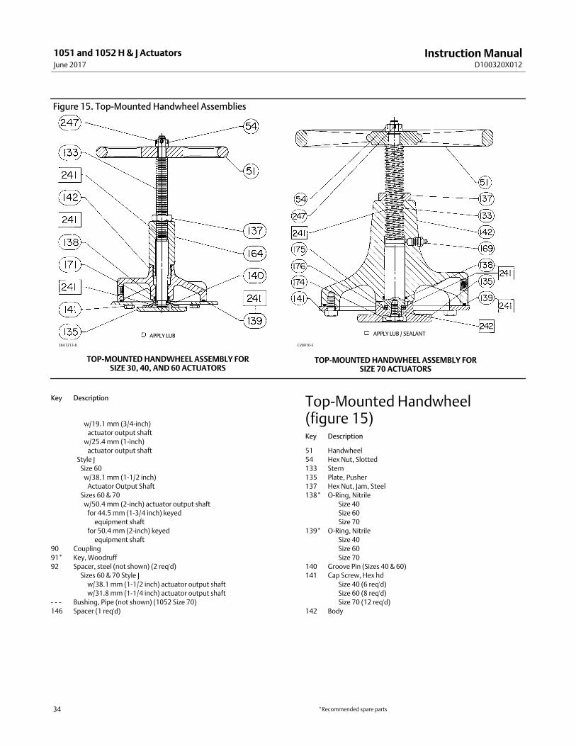
Instruction ManualD100320X012
1051 and 1052 H & J ActuatorsJune 2017
34
Figure 15. Top‐Mounted Handwheel Assemblies
38A1213‐B CV8010‐E
TOP-MOUNTED HANDWHEEL ASSEMBLY FORSIZE 30, 40, AND 60 ACTUATORS
TOP-MOUNTED HANDWHEEL ASSEMBLY FORSIZE 70 ACTUATORS
APPLY LUB APPLY LUB / SEALANT
Key Description
w/19.1 mm (3/4‐inch)
actuator output shaft
w/25.4 mm (1‐inch)
actuator output shaft
Style J
Size 60
w/38.1 mm (1‐1/2 inch)
Actuator Output Shaft
Sizes 60 & 70
w/50.4 mm (2‐inch) actuator output shaft
for 44.5 mm (1‐3/4 inch) keyed
equipment shaft
for 50.4 mm (2‐inch) keyed
equipment shaft
90 Coupling
91* Key, Woodruff
92 Spacer, steel (not shown) (2 req'd)
Sizes 60 & 70 Style J
w/38.1 mm (1‐1/2 inch) actuator output shaft
w/31.8 mm (1‐1/4 inch) actuator output shaft
-�-�- Bushing, Pipe (not shown) (1052 Size 70)
146 Spacer (1 req'd)
Top‐Mounted Handwheel(figure 15)Key Description
51 Handwheel
54 Hex Nut, Slotted
133 Stem
135 Plate, Pusher
137 Hex Nut, Jam, Steel
138* O‐Ring, Nitrile
Size 40
Size 60
Size 70
139* O‐Ring, Nitrile
Size 40
Size 60
Size 70
140 Groove Pin (Sizes 40 & 60)
141 Cap Screw, Hex hd
Size 40 (6 req'd)
Size 60 (8 req'd)
Size 70 (12 req'd)
142 Body
*Recommended spare parts

Instruction ManualD100320X012
1051 and 1052 H & J ActuatorsJune 2017
35
Key Description
164 Body Extension (Sizes 40 & 60)
169 Grease Fitting (Size 70)
171 Spacer (Size 60)
174 Retaining Screw (Size 70
175 Thrust Bearing (Size 70)
241 Lithium Grease (not furnished w/travel stop)
242 Thread Locking Adhesive (High Strength)
(not furnished w/travel stop)
(1052 Size 70 only)
246 Spacer (Sizes 60 & 70)
247 Pin, Cotter, Stainless Steel
Adjustable Up Travel Stop (figure 16)133 Stem
135 Plate, Pusher
137 Nut, Travel Stop (Size 70)
138* O‐Ring, Nitrile
Size 40
Size 60
Size 70
139* O‐Ring, Nitrile
Size 40
Size 60
Size 70
140* Groove Pin
Size 40
Size 60
141 Cap Screw, Hex Hd, Steel
Size 40 (6 req'd)
Size 60 (8 req'd)
Size 70 (12 req'd)
142 Body
164 Body Extension (Sizes 40 & 60)
169 Grease Fitting, Steel (Size 70)
171 Spacer (Size 60)
Key Description
174 Retaining Screw, Steel (Size 70)
175 Thrust Bearing
176 Bearing Race, Thrust (1052, Size 70) (2 req'd)
187 Travel stop cap (Size 70)
241 Lithium Grease (not furnished w/travel stop)
242 Thread Locking Adhesive (High Strength)
(not furnished w/travel stop)
(1052 Size 70 only)
Adjustable Down Travel Stop (figure 17)54 Hex Nut
�1051
��Size 40 (1 req'd)
��Size 60 (2 req'd)
�1052
��Size 40 (1 req'd)
��Sizes 60 & 70 (2 req'd)
63 Flange Nut (Sizes 40 & 70)
133 Travel Stop Stem
134 Washer, Plain
139* O‐Ring, Nitrile
Size 40
Size 60
Size 70
141 Cap Screw, Hex hd
Size 40 (6 req'd)
Size 60 (8 req'd)
Size 70 (12 req'd)
142 Travel Stop Body
187 Travel Stop Cap
189 Hex Nut, Jam
Sizes 40 & 60 (1 req'd)
Size 70 (2 req'd)
241 Lithium Grease (not furnished w/travel stop)
*Recommended spare parts

Instruction ManualD100320X012
1051 and 1052 H & J ActuatorsJune 2017
36
Figure 16. Adjustable Up Travel Stops
28A1207‐B
28A1214‐A
CV8057-D/DOC
ADJUSTABLE UP TRAVEL STOP FORSIZE 30 AND 40 ACTUATORS
ADJUSTABLE UP TRAVEL STOP FORSIZE 60 ACTUATORS
ADJUSTABLE UP TRAVEL STOP FOR SIZE 701052 ACTUATORS
APPLY LUB / SEALANT
APPLY LUB APPLY LUB

Instruction ManualD100320X012
1051 and 1052 H & J ActuatorsJune 2017
37
Figure 17. Adjustable Down Travel Stop
NOTE:FOR SIZE 60 ACTUATORS, A SECOND HEX NUT (KEY 54) IS USED INTHE PLACE OF THE HEX NUT (KEY 63)
38B5654‐BA7238

Instruction ManualD100320X012
1051 and 1052 H & J ActuatorsJune 2017
38

Instruction ManualD100320X012
1051 and 1052 H & J ActuatorsJune 2017
39

Instruction ManualD100320X012
1051 and 1052 H & J ActuatorsJune 2017
40
Emerson Automation Solutions Marshalltown, Iowa 50158 USASorocaba, 18087 BrazilCernay 68700 FranceDubai, United Arab EmiratesSingapore 128461 Singapore
www.Fisher.com
The contents of this publication are presented for informational purposes only, and while every effort has been made to ensure their accuracy, they are notto be construed as warranties or guarantees, express or implied, regarding the products or services described herein or their use or applicability. All sales aregoverned by our terms and conditions, which are available upon request. We reserve the right to modify or improve the designs or specifications of suchproducts at any time without notice.
� 1984, 2017 Fisher Controls International LLC. All rights reserved.
Fisher, FISHTAIL, and TopWorx are marks owned by one of the companies in the Emerson Automation Solutions business unit of Emerson Electric Co.Emerson Automation Solutions, Emerson, and the Emerson logo are trademarks and service marks of Emerson Electric Co. All other marks are the propertyof their respective owners.
Neither Emerson, Emerson Automation Solutions, nor any of their affiliated entities assumes responsibility for the selection, use or maintenanceof any product. Responsibility for proper selection, use, and maintenance of any product remains solely with the purchaser and end user.