First Results of Laser Ranging to the CHAMP Retroreflector · First Results of Laser Ranging to the...
7
First Results of Laser Ranging to the CHAMP Retroreflector Ludwig Grunwaldt, Reinhart Neubert GeoForschungsZentrum Potsdam, Div.1: Kinematics and Dynamics of the Earth Telegrafenberg A 17, D-14473 Potsdam, Germany Tel.: (+49)-331-288-1733, -1153, Fax.: (+49)-331-288-1732, e-mail: [email protected] Kasimirs Lapushka Astronomical Institute, University of Latvia Boulevard Rainis 19, Riga, LV-1586 Latvia e-mail: [email protected] Summary The geophysical research satellite CHAMP was launched on July 15, 2000 into a 460 km near-polar orbit. An intensive laser tracking campaign yielded several hundred SLR passes so far. The CHAMP retro- reflector was designed with special emphasis on a high link budget in combination with negligible target signature in order to serve as calibration device for the onboard GPS receiver. Comparisons of the expected and measured signal strength distributions over a pass together with some observed peculiarities in signal reception are discussed. Retroreflectors of identical design will be used for the two satellites of the upcoming GRACE mission. Short Description of the CHAMP Laser Retroreflector (LRR) The final design and realization of the CHAMP retroreflector are decribed in full detail in [1]. We repeat here only the main characteristics of the optical and mechanical layout: The LRR is formed of an array consisting of four cube corner prisms mounted in a compact aluminum frame (cf. Fig. 1). This special design ensures that only one prism contributes to the return signal in most of the cases, except for short periods near the culmination of the satellite where the signals of two prisms start to interfere. Because of the small size of the array the signature cannot be resolved by most of the existing SLR ground stations though. Figure 1 The CHAMP Laser Retroreflector Array
Transcript of First Results of Laser Ranging to the CHAMP Retroreflector · First Results of Laser Ranging to the...
First Results of Laser Ranging to the CHAMP Retroreflector Ludwig Grunwaldt, Reinhart Neubert
GeoForschungsZentrum Potsdam, Div.1: Kinematics and Dynamics of the Earth Telegrafenberg A 17, D-14473 Potsdam, Germany
Tel.: (+49)-331-288-1733, -1153, Fax.: (+49)-331-288-1732, e-mail: [email protected] Kasimirs Lapushka
Astronomical Institute, University of Latvia Boulevard Rainis 19, Riga, LV-1586 Latvia
e-mail: [email protected]
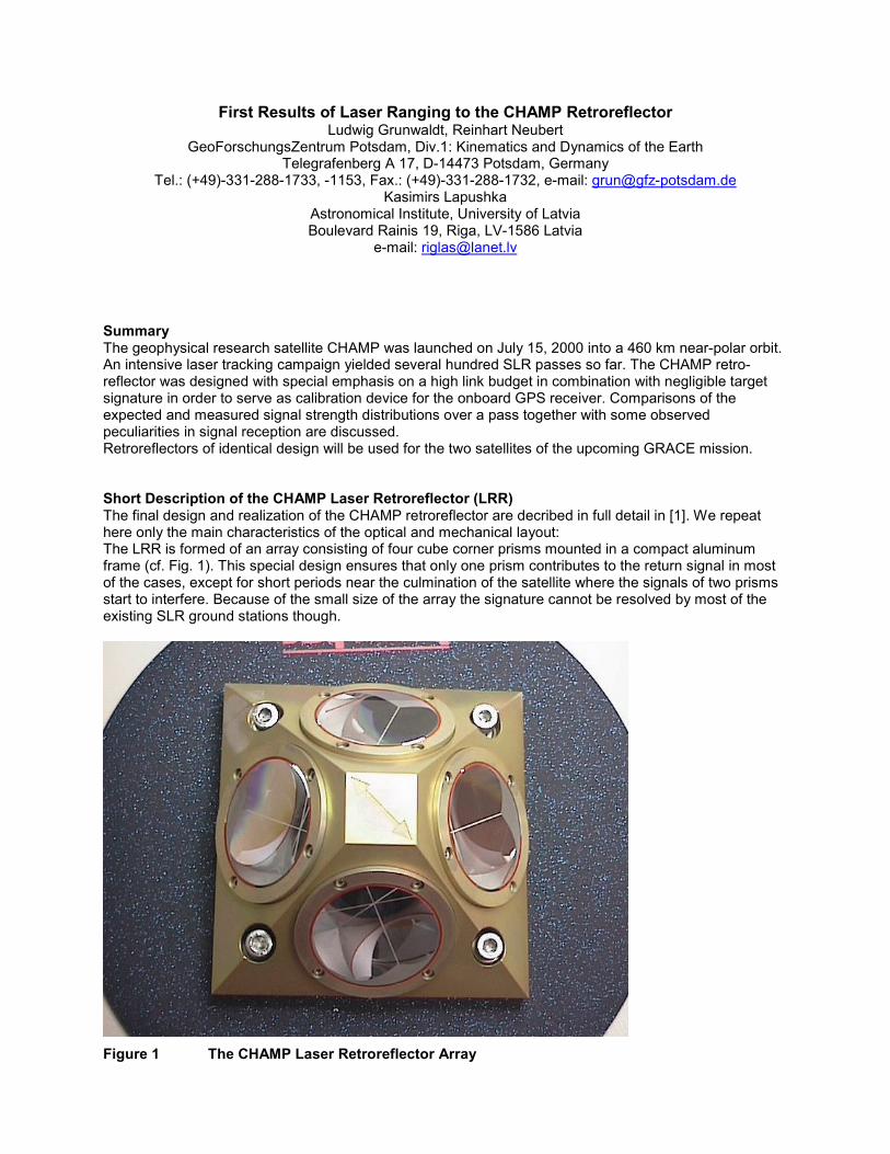
Summary The geophysical research satellite CHAMP was launched on July 15, 2000 into a 460 km near-polar orbit. An intensive laser tracking campaign yielded several hundred SLR passes so far. The CHAMP retro-reflector was designed with special emphasis on a high link budget in combination with negligible target signature in order to serve as calibration device for the onboard GPS receiver. Comparisons of the expected and measured signal strength distributions over a pass together with some observed peculiarities in signal reception are discussed. Retroreflectors of identical design will be used for the two satellites of the upcoming GRACE mission. Short Description of the CHAMP Laser Retroreflector (LRR) The final design and realization of the CHAMP retroreflector are decribed in full detail in [1]. We repeat here only the main characteristics of the optical and mechanical layout: The LRR is formed of an array consisting of four cube corner prisms mounted in a compact aluminum frame (cf. Fig. 1). This special design ensures that only one prism contributes to the return signal in most of the cases, except for short periods near the culmination of the satellite where the signals of two prisms start to interfere. Because of the small size of the array the signature cannot be resolved by most of the existing SLR ground stations though.
Figure 1 The CHAMP Laser Retroreflector Array

Table 1: Specifications of the cube corner prisms for the CHAMP LRR: Vertex length 28 mm Clear aperture of the front face 38 mm Dihedral angle offset -3.8” (smaller than 90°) Radius of the curvature of the front face 500 m (convex) Index of refraction @ 532 nm 1.461 Nominal separation of the far field maxima 24” Nominal width of the far field peaks (20% intensity of max.) 10” The prisms are cemented using space-qualified two-component silicon rubber glue into mounting flanges which are screwed into the frame, a 45°-pyramid with outer dimensions of (100 x 100 x 48) mm. The cube corner prisms produce two-spot far field diffraction patterns (cf. Fig. 2) in order to cope with the effect of velocity aberration. Proper orientation of the prisms ensures that one of the far field lobes is directed to the apparent position of the station as seen from the reflector. The four selected flight prisms no. 2, 4 ,5 and 6 yield the following far field diffraction patterns at vertical light incidence (cf. Fig. 2): Figure 2 Far field patterns of the four selected LRR flight prisms as computed from the
interferometrically observed wave fronts. Scale unit: 2 arcsec.

The CHAMP Attitude Control As a combined gravity / magnetic field / atmospheric mission, CHAMP is actively stabilized in all three main axes (Roll, Pitch and Yaw) by means of magnetorquers and cold gas thrusters. In order to minimize the disturbances onto the highly sensitive on-board accelerometer, the magnetorquers perform a continous “soft” attitude control most of the time and cold gas thrusters are fired only in case the deadband of ±2° is exceeded for a given axis.
Figure 3 Schematic of the CHAMP Spacecraft The nominal attitude of CHAMP is:
• Magnetometry boom in flight direction (representing the spacecraft X-axis / Roll) • S-Band antenna and LRR nadir-pointing (representing the spacecraft Z-axis / Yaw)
The reason for flying with the boom in forward direction (a backward-directed boom would result in a more stable flight configuration from an astrodynamical point of view) is the need to have the GPS limb sounding antenna array in anti-velocity direction. This array is designed to track the signals of the GPS constellation when such a satellite is descending beyond the local horizon thus sending radio signals through the lower layers of the atmosphere and allowing for the determination of vertical profiles of pressure, temperature and water vapor.

In the fine-pointing mode the attitude is determined by precise star sensors mounted both on the satellite body and on the magnetometry boom. The attitude can be derived to a few arcseconds after post-processing of the star sensor quaternions on ground. Different from other satellites, CHAMP does not fly a sun-pointed safe-mode in case of a transient, more serious onboard problem. In such a rare event only the yaw-steering is abandoned and the attitude is controlled by the cold-gas thrusters exclusively while coarse Earth-Sun sensors are used for attitude determination. This means that the direction of the boom with respect to the flight direction becomes unpredictable for some time, but both the S-Band antenna and the LRR are still nadir-pointing (with a somewhat degraded accuracy) and thus laser ranging will not be disabled by a temporary safe-mode transition. During the first days of the mission, CHAMP was flying with the boom in anti-velocity direction for some tests of the attitude control system; this transient attitude was maintained until July 24, 2000 when a boom-slew manouevre was executed which finally resulted in a boom orientation parallel to the flight direction. Comparison of CHAMP LRR Return Signal with Theory The CHAMP liftoff took place on July 15, 2000 at 12:00:00 UTC from the Plesetsk launch site. The first laser returns were obtained 36 hours later by the SLR station 1884 Riga. A total of 83 laser passes from 17 ground stations was obtained by the end of July. The return signal strength from the CHAMP LRR array was reported to be strong under mid elevations and still reasonable near to culmination and down to about 15° elevation. Due to the specific design of the array, the signal from the CHAMP LRR is expected not to be uniform over a pass. The two-spot far field lobes of the individual prisms tend to broaden with increasing angle of light incidence to the front surface [1]. Thus the return signal becomes distributed over a larger area and weakens in comparison with the optimum case of light incidence normal to the prism front surface. The minimum angle of light incidence can be expected symmetrically before and after the culmination of CHAMP for a given station whereas some drop in the signal should become obvious near culmination and towards begin and end of the track. This symmetry is caused by the way the CHAMP LRR is mounted on the satellite with respect to its flight direction (cf. Fig.4). With the exception of near-zenithal passes only two prisms contribute to the return signal: one before and one after culmination with some joint action for a short period when both prisms are about symmetrical to the observer.
Figure 4 The CHAMP LRR as seen from ground (right-hand arrow indicates velocity vector)
x V
x
y
xy
y
x
y
x
24
5 6
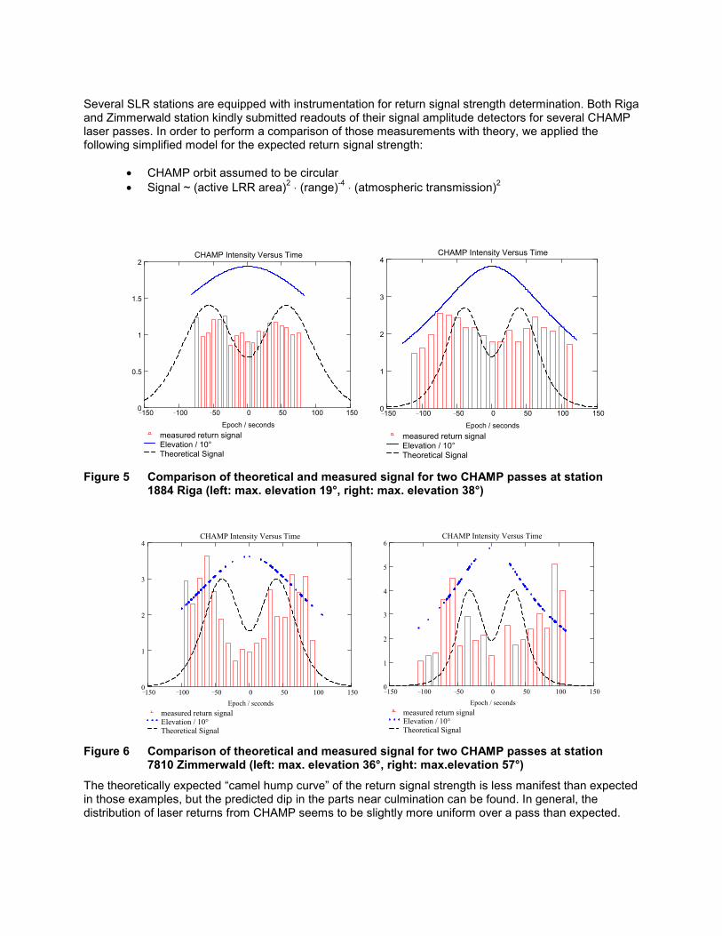
Several SLR stations are equipped with instrumentation for return signal strength determination. Both Riga and Zimmerwald station kindly submitted readouts of their signal amplitude detectors for several CHAMP laser passes. In order to perform a comparison of those measurements with theory, we applied the following simplified model for the expected return signal strength:
• CHAMP orbit assumed to be circular • Signal ~ (active LRR area)2 ⋅ (range)-4 ⋅ (atmospheric transmission)2
Figure 5 Comparison of theoretical and measured signal for two CHAMP passes at station 1884 Riga (left: max. elevation 19°, right: max. elevation 38°)
Figure 6 Comparison of theoretical and measured signal for two CHAMP passes at station 7810 Zimmerwald (left: max. elevation 36°, right: max.elevation 57°)
The theoretically expected “camel hump curve” of the return signal strength is less manifest than expected in those examples, but the predicted dip in the parts near culmination can be found. In general, the distribution of laser returns from CHAMP seems to be slightly more uniform over a pass than expected.
150 100 50 0 50 100 1500
0.5
1
1.5
2
measured return signalElevation / 10°Theoretical Signal
CHAMP Intensity Versus Time
Epoch / seconds150 100 50 0 50 100 1500
1
2
3
4
measured return signalElevation / 10°Theoretical Signal
CHAMP Intensity Versus Time
Epoch / seconds
150 100 50 0 50 100 1500
1
2
3
4
measured return signalElevation / 10°Theoretical Signal
CHAMP Intensity Versus Time
Epoch / seconds
150 100 50 0 50 100 1500
1
2
3
4
5
6
measured return signalElevation / 10°Theoretical Signal
CHAMP Intensity Versus Time
Epoch / seconds

Peculiarities in Signal Reception The SLR station 1884 Riga submitted several records of return signal strength from the CHAMP LRR which deviate from the “nominal” signal distribution as shown above and indicate a drop in signal strength after culmination. A clear dependence from the pass geometry was indicated. When CHAMP was moving from north to south, passes observed east from the station showed the signal to be fading after culmi-nation while this effect was absent during passes observed in the west (cf. Fig. 7, 8).
Figure 7 Pass with decreasing signal strength after culmination
Figure 8 Pass without decreasing signal strength after culmination
CHAMP: Laser Return Signal Amplitude(09/07/2000 Station 1884 Riga)
0
200
400
600
800
1000
1200
68550 68600 68650 68700 68750 68800Time [seconds of day]
Ran
ge [k
m]
0
1000
2000
3000
4000
5000
6000
Sign
al a
mpl
itude
Signal amplitude
Range
Maximum elevation 35° east of stationSatellite moving from north to south
CHAMP: Laser Return Signal Amplitude(09/14/2000 Station 1884 Riga)
0
200
400
600
800
1000
1200
70200 70250 70300 70350 70400Time [seconds of day]
Ran
ge [k
m]
0
1000
2000
3000
4000
5000
6000Si
gnal
am
plitu
de
Range
Signal amplitude
Maximum elevation 38° west of stationSatellite moving from north to south

Due to the well-defined attitude of CHAMP and the known orientation of the reflector with respect to the SLR station for any given moment, there is an unambiguous contribution of every single prism to the return signal (cf. Fig. 4):
N – S pass east / S – N pass west of the station: prism 2 before, prism 4 after culmination N – S pass west / S – N pass east of the station: prism 5 before, prism 6 after culmination
The effect described above could thus be caused e.g. by a somehow distorted far field of prism 4 with respect to the far fields of the other prisms. Fig. 2 shows no sign of any significant irregularities in the far field pattern of prism 4 instead. The signal distribution appears to be quite similar to the one of prism 2 which acts in such passes before culmination. A possible explanation for the reduced return signal strength could be the partial obscuration of the entrance aperture of prism 4 e.g. by parts of the CHAMP nadir radiator which is fixed very close to the LRR array. This radiator is made of very flexible MLI (Multi-Layer Insulation) foil which could have become slightly deformed during launch. Of course it is nearly impossible to prove this hypothesis by independent measurements. The general thermal behaviour of CHAMP is very close to the predicted values and indicates that the nadir radiator as a whole is in good shape. We will need more independent observations of the above described effect in order to draw final conclusions. A second peculiarity in laser signal reception was reported by the station 1884 Riga as well: during near-zenithal passes observed at the end of September 2000 no return signal could be detected in the ascending part of the pass until the satellite had reached a certain elevation. Then the signals started with full amplitude and could easily be tracked. This effect was absent for the descending part of the pass. It could also not be observed during the first days after launch when few near-zenithal passes were tracked by the Riga station. The explanation for this transient lack of return signals below a certain elevation (about 30°) can be found in the design of the spacecraft (cf. Fig. 3) and the location of the LRR. The retroreflector array is mounted on a bracket below the centre of mass of the satellite and thus in the symmetry axis of the satellite body. With CHAMP approaching a ground observer head-on, the LRR is obscured both by the Digital Ion-Driftmeter / Planar Langmuir Probe and the S-Band antenna boom until the satellite has reached an elevation of about 30° and the reflector array becomes visible within short time. During the first days of the mission CHAMP was flying with the boom in anti-velocity direction and the effect was absent due to the lack of obscuring elements for the LRR in this attitude. In the descending part of the pass a similar problem should have appeared but was obviously masked by tracking problems when the satellite entered the eclipse after culmination. Conclusions The CHAMP retroreflector has proven the possibility to use a densely packed array with the minimum number of prisms (4) for a LEO spacecraft in order to obtain a sufficiently high return signal for easy target acquisition under both night- and daytime conditions. Only one prism is contributing to the return signal in most of the cases except for near-zenithal passes. This results in a very low target signature which cannot be resolved by most of the presently existing SLR stations. Single-shot ranging accuracies well below 5 mm were reported. Some peculiarities in signal reception can be explained by the CHAMP spacecraft design and attitude control. The reported effect of reduced signal strength under special conditions still needs an explanation. LRR arrays of similar design will be used for both GRACE satellites which are scheduled for launch in late 2001. Both arrays are presently undergoing their final tests. Reference [1] R. Neubert, L. Grunwaldt, J. Neubert: The Retro-Reflector for the CHAMP Satellite: Final Design
and Realization, Proceedings of the 11th Workshop on Laser Ranging, Deggendorf Sept. 1998, pp. 260-270