First Order Archwire Deflections: Comparing Conventional ...
118
University of Connecticut OpenCommons@UConn SoDM Masters eses School of Dental Medicine 2008 First Order Archwire Deflections: Comparing Conventional, Active Self-Ligating and Passive Self- Ligating Mechanisms Michael B. Holbert University of Connecticut Health Center Follow this and additional works at: hps://opencommons.uconn.edu/sodm_masters Part of the Dentistry Commons Recommended Citation Holbert, Michael B., "First Order Archwire Deflections: Comparing Conventional, Active Self-Ligating and Passive Self-Ligating Mechanisms" (2008). SoDM Masters eses. 171. hps://opencommons.uconn.edu/sodm_masters/171
Transcript of First Order Archwire Deflections: Comparing Conventional ...

University of ConnecticutOpenCommons@UConn
SoDM Masters Theses School of Dental Medicine
2008
First Order Archwire Deflections: ComparingConventional, Active Self-Ligating and Passive Self-Ligating MechanismsMichael B. HolbertUniversity of Connecticut Health Center
Follow this and additional works at: https://opencommons.uconn.edu/sodm_masters
Part of the Dentistry Commons
Recommended CitationHolbert, Michael B., "First Order Archwire Deflections: Comparing Conventional, Active Self-Ligating and Passive Self-LigatingMechanisms" (2008). SoDM Masters Theses. 171.https://opencommons.uconn.edu/sodm_masters/171
First order archwire deflections.
Comparing conventional, active self-ligating
and passive self-ligating mechanisms.
Michael B. Holbert
B.S., Pennsylvania State University, 1996
D.D.S., University of North Carolina, 2003
A Thesis
Submitted in Partial Fulfillment of the
Requirements for the Degree of
Master of Dental Science
at the
University of Connecticut
2008

APPROVAL PAGE
Master of Dental Science Thesis
First order archwire deflections. Comparing conventional, active self-ligating
and passive self-ligating brackets
Presented by Michael B. Holbert, B.S., D.D.S.
Major Advisor: Andrew J. Kuhlbert, D.M.D.,M.D.S.
Associate Advisor: Donald R. Peterson, B.S., M.S., Ph.D.
Associate Advisor: Flavio Uribe, D.D.S.,M.D.S.
University of Connecticut
2008

Acknowledgements:
I would like to offer my sincere thanks to my advisors, Dr. Andy Kuhlberg, Dr. Don
Peterson and Dr. Bruce Havens, for their knowledge, support and patience during our
lengthy brainstorming sessions. They forced me to be creative in my approach to
research and problem solving. Not only did I learn to think like an engineer, but I was
given the task of working with engineering students to design and fabricate a novel
mechanical testing apparatus.
I offer my gratitude to Dr. Ravindra Nanda for introducing me to Michael Brault of
Ultimate Wireforms Inc. Michael and all of the engineers provided me guidance
regarding the properties and performance of nickel titanium wires that was integral to this
project. I would not have any of the data in this thesis if they had not allowed me access
to their instrumentation lab for testing.
I would like to thank the faculty, residents and staff of the University Of Connecticut
Department Of Orthodontics for the many lessons you have taught me over these past
three years. Without the friendship of my co-residents my time at UConn would not have
been as enjoyable. My thanks to Dr. Lorin Trettel for your guidance and friendship. A
special thanks to Dr. Jonny Feldman for the mentorship and friendship you provided
during my three years at the University of Connecticut.
Finally, a very special thanks to my wife Paige for her continual love and support, which
I will return in full as she ventures into her endodontic residency this Summer.

Table of Contents
Title Page
Approval Page
Acknowledgements
Table of Contents
List of Tables
List of Figures
Abstract
Introduction
Background
Orthodontic Tooth Movement - Anatomy and Biology of Tooth Movement - Biomechanics of Tooth Movement
Fundamentals of Static Equilibrium The Fixed Orthodontic Appliance Orthodontic Treatment Sequence
Orthodontic Archwires - Archwire Properties
- Springback - Load Deflection - Modulus of Resilience
- The Nickel Titanium Archwire - Physical Properties of Nickel Titanium - Shape Memory - Superelasticity - Hysteresis
Orthodontic Archwire Ligation - Elastomeric and Wire Ligatures - Self Ligating Brackets - Active and Passive Ligation
Friction in Orthodontics - Definition of Friction
vii
Objectives
- Material Composition - Material Dimension - Bracket Ligation - Clinical Studies
Hypothesis
Materials and Methods
Brackets and Wires Tested Testing Apparatus Calibration Cantilevered Archwire Test Three Point Bending Test Data Acquisition and Analysis
Results
Cantilever Test - Bracket Play - Deactivation Force - Superelastic Kange
Three Point Bend Test - Imm Deflection - 2mm Deflection - 3mm Deflection
Discussion
Conclusions
Figures
Tables
References
Appendix

List of Tables
Table
Table I: Description of Brackets Tested
Table 11: Description of Wires Tested
Table 111: Mean Degrees of Bracket Play
Table IV: Cantilever Deactivation Force at lmm, 2mm and 3mm Deflection
A: 0.014" SE NiTi
B: 0.01 6" SE NiTi
C: 0.01 8" SE NiTi
D: 0.020" SE NiTi
Table V: Mean Superelastic Range with 4mm Cantilever Deflection
Table VI: Three Point Deactivation Force at 1 mm, 2mm and 3mm Deflection
A: 0.014'' SENjTi
B: 0.016" SENiTi
C: 0.01 8" SE NiTi
D: 0.020" SE NiTi

List of Figures
Figure
Figure 1: Clinical Observation: Derotation with Translation of C, (Redrawn from: www.speedsystem.com/HTML/the - speed- appliancelhow-speed - works/04~rotation~case~example.html)
Figure 2: Anatomy of the Periodontal Ligament Attachment (Redrawn from: http://images.google.com/imgres?imgurl= http://www.studiodentaire.com/images/en/periodontal - ligament -en.j pg)
Figure 3: Effect of Continuous vs. Discontinuous Orthodontic Force (From: van Leeuwen, E. J., J. C. Maltha, et al., Eur J Oral Sci, 1999, 107(6): 468-74)
Figure 4: Center of Mass and Center of Resistance (From: Nanda R., Biomechanics and Esthetic Strategies in Clinical Orthodontics., 2005, St. Louis, Elsevier Saunders: 1- 16)
Figure 5: Center of Resistance: Relating Alveolar Bone and Root Length 4 (From: Nanda R., Biomechanics and Esthetic Strategies in Clinical Orthodontics., 2005, St. Louis, Elsevier Saunders: 1 - 16)
Figure 6: Moment of the Force (MF) 4 (From: Nanda R., Biomechanics and Esthetic Strategies in Clinical Orthodontics., 2005, St. Louis, Elsevier Saunders: 1 - 16)
Figure 7: Moment of a Couple with Pure Rotation 5 (From: Nanda R., Biomechanics and Esthetic Strategies in Clinical Orthodontics., 2005, St. Louis, Elsevier Saunders: 1-16)
Figure 8: Equivalent Force Systems Diagram 5 (From: Nanda R., Biomechanics and Esthetic Strategies in Clinical Orthodontics., 2005, St. Louis, Elsevier Saunders: 1 - 16)
Figure 9: Uncontrolled and Controlled Tipping 6 (From: Nanda R., Biomechanics and Esthetic Strategies in Clinical Orthodontics., 2005, St. Louis, Elsevier Saunders: 1-16)

Figure 10: Bodily Tooth Movement and Root Movement 6 (From: Nanda R., Biomechanics and Esthetic Strategies in Clinical Orthodontics., 2005, St. Louis, Elsevier Saunders: 1 - 16)
Figure 11: Pure Rotation about the Center of Resistance 7 (From: Nanda R., Biomechanics and Esthetic Strategies in Clinical Orthodontics., 2005, St. Louis, Elsevier Saunders: 1-1 6)
Figure 12: 2" and 3rd Order BracketIArchwire Interaction 13 (From: Nanda R., Biomechanics and Esthetic Strategies in Clinical Orthodontics., 2005, St. Louis, Elsevier Saunders: 1-16)
Figure 13: Stress / Strain Diagram of Archwire Properties 16 (From: Nanda R., Biomechanics and Esthetic Strategies in Clinical Orthodontics., 2005, St. Louis, Elsevier Saunders: 1 - 16)
Figure 14: Comparing Angular and Torsional Deflections 17 (From: Drake, S. R., D. M. Wayne, et al., Am J Orthod, 1982 82(3): 206- 10.)
Figure 15: MomentIDeflection Comparison of Stainless Steel and Nitinol 17 (From: Andreasen, G. F. and R. E. Morrow, Am J Orthod, 1978 73(2): 142-5 1 .)
Figure 16: Comparison of Chinese NiTi, Nitinol and Stainless Steel (From: Burstone, C. J., B. Qin, et al., Am J Orthod, 1985 87(6): 445-52.)
Figure 17: NiTi Phase Comparison and Temperature Hysteresis 18 (From: Ryhanen, J, 1999, University of Oulu http://herkules.oulu.fi/isbn95 142522 17/htmlIx3 17.html)
Figure 18: Nickel Titanium Stress Hysteresis 2 1 (From: Liaw, Y. C., Y. Y. Su, et al., Am J Orthod Dentofacial Orthop, 2007,131(5): 578 e12-8.)

Figure 19: Comparing Elastomeric Force at Various Time Points (From: Taloumis, L. J., T. M. Smith, et al., Am J Orthod Dentofacial Orthop, 1997, 11 l(1): 1 - 1 1 .)
Figure 20: Pictures of Elastomerics Before and After Activation (From: Taloumis, L. J., T. M. Smith, et al., Am J Orthod Dentofacial Orthop, 1997, 11 l(1): 1 - 1 1 .)
Figure 21 : Passive Ligation Mechanism (Photo of Carriere bracket by Michael Holbert, DDS)
Figure 22: Interactive Ligation Mechanism (Photo of In-Ovation R bracket by Michael Holbert, DDS)
Figure 23: Custom Testing Fixture with Mounted Brackets (Photos taken by Michael Holbert, DDS)
Figure 24: Tinius Olsen H 1 K-S Mechanical Testing Instrument (Photos taken by Michael Holbert, DDS)
Figure 25: Degrees of Bracket Play with Cantilever Deflection
Figure 26: Cantilever Load Deflection Curves
A: 0.01 4" SE NiTi
B: 0.016" SE NiTi
C: 0.01 8" SE NiTi
D: 0.020" SE NiTi
Figure 27: Mean Degrees of Bracket Play with Cantilever Test
Figure 28: Mean Deactivation Force with lmm Cantilever Deflection
Figure 29: Mean Deactivation Force with 2mm Cantilever Deflection
Figure 30: Mean Deactivation Force with 3mm Cantilever Deflection
Figure 31: Mean Superelastic Range with Cantilever Test

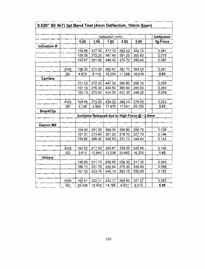
Figure 32: Three Point Bend Load-Deflection Curves
A: 0.01 4" SE NiTi
B: 0.016" SENiTi
C: 0.01 8" SE NiTi
D: 0.020" SE NiTi
Figure 33: Mean Deactivation Forces at lmm of Three Point Deflection 74
Figure 34: Mean Deactivation Forces at 2mm of Three Point Deflection 75
Figure 35: Mean Deactivation Forces at 3mm of Three Point Deflection 7 5
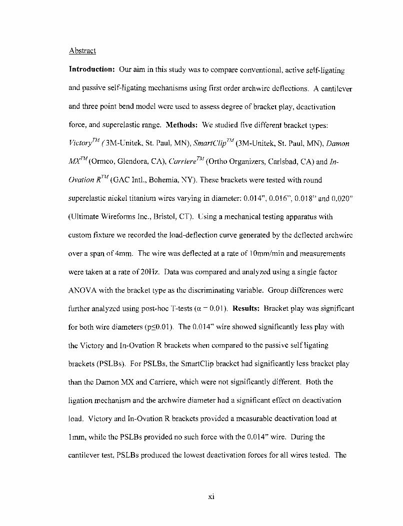
Abstract
Introduction: Our aim in this study was to compare conventional, active self-ligating
and passive self-ligating mechanisms using first order archwire deflections. A cantilever
and three point bend model were used to assess degree of bracket play, deactivation
force, and superelastic range. Methods: We studied five different bracket types:
victoryTM (3M-Unitek, St. Paul, MN), smartClipTM (3M-Unitek, St. Paul, MN), Damon
hYTM ( ~ r m c o , Glendora, CA), CarriereTM (Ortho Organizers, Carlsbad, CA) and In-
Ovation R~~ (GAC Intl., Bohemia, NY). These brackets were tested with round
superelastic nickel titanium wires varying in diameter: 0.014", 0.016", 0.018" and 0.020"
(Ultimate Wireforms Inc., Bristol, CT). Using a mechanical testing apparatus with
custom fixture we recorded the load-deflection curve generated by the deflected archwire
over a span of 4mm. The wire was deflected at a rate of 10mmImin and measurements
were taken at a rate of 20Hz. Data was compared and analyzed using a single factor
ANOVA with the bracket type as the discriminating variable. Group differences were
further analyzed using post-hoc T-tests (a = 0.01). Results: Bracket play was significant
for both wire diameters (p50.01). The 0.014" wire showed significantly less play with
the Victory and In-Ovation R brackets when compared to the passive self ligating
brackets (PSLBs). For PSLBs, the Smartclip bracket had significantly less bracket play
than the Damon MX and Carriere, which were not significantly different. Both the
ligation mechanism and the archwire diameter had a significant effect on deactivation
load. Victory and In-Ovation R brackets provided a measurable deactivation load at
lmm, while the PSLBs provided no such force with the 0.014" wire. During the
cantilever test, PSLBs produced the lowest deactivation forces for all wires tested. The

three point bend test showed similar results with small diameter wires. As the degree of
deflection and archwire diameter increased, the PSLBs displayed reduced deactivation
forces, which are related to significant binding and increased sliding frictional resistance.
The superelastic range varied significantly for the various bracket types (p_<0.01).
Victory provided the largest superelastic range for all wires except the 0.020". Of the
SLBs tested, In-Ovation R displayed the larger superelastic range. The 0.014," test
showed a significant difference in superelastic range for all brackets except the Damon
MX and Carriere, which were not significantly different from each other. Conclusions:
The type of ligation has a significant effect on the degree of bracket play, force of
deactivation and superelastic range. These factors influence the clinician's ability to
achieve full first-order correction and to maintain light, continuous forces over a wide
range of activation. The clinician should consider the degree of correction needed and
type of ligation when selecting the appropriate alignment wire.

Introduction
We have observed clinically that a rotated tooth, when ligated to a straight archwire, does
not rotate about its center of resistance, but instead rotates about an axis located at or near
the bracket of the tooth in motion (See Figure 1). If only a pure moment was present at
the bracketlarchwire interface we would expect rotation about the center of resistance,
but this is not the case. The type of movement observed, translation of the center of
resistance and rotation about the bracket, requires the presence of both a moment and a
force. In the case of a rotated tooth, the activation of the archwire into the bracket slot
provides a buccolingual couple responsible for the rotational moment (See Figure 1). But
how can we explain translation of the center of resistance? We surmise that the force
responsible for translating the center of resistance in a mesiodistal direction is the force of
friction acting opposite the direction of derotation. This leads us to question the role of
ligation in first order orthodontic tooth movement and whether variations in bracket
ligation type affect the first order force system. We plan to test this hypothesis by
assessing the load-deflection curves for conventional, active self-ligating and passive
self-ligating brackets when subject to first order archwire deflections.
Background
Orthodontic Tooth Movement
Orthodontic tooth movement is accomplished through the application of force to the
supportive structures of the teeth. The fixed orthodontic appliance, which is responsible

for the delivery of force, is selected and activated by the clinician. The clinician
determines the magnitude and direction of force to be applied to the dentition. Activation
of the orthodontic appliance produces stress and strain within the supportive structures of
the teeth. These supportive structures are insensitive to the bracket design, wire shape or
alloy being used in the orthodontic appliance. Instead, their response is based solely on
the stresses and strains occurring in the local environment. To achieve a precise biologic
response, precise orthodontic stimuli must be applied. Even though there is variability
among individuals' biologic response, understanding biomechanics and the delivery of
orthodontic force improves treatment by reducing variability in the expected treatment
1 outcome .
Anatomv and the Biological Response:
The supportive structures of the teeth consist of the alveolar bone, periodontal ligament
(PDL), mesenchymal cells and ground substance. The alveolar bone surrounds the tooth
root and is covered by a thin layer of cortical bone called the lamina dura. From the
lamina dura extend the collagenous fibers of the periodontal ligament. These fibers are
embedded in alveolar bundle bone on one side, extend across the 0.5mm ligament space
and attach to the cementum layer of the tooth root on the other side. Additionally, the
PDL space contains a network of capillaries and nerve fibers, as well as an amorphous
ground substance consisting of connective tissue polysaccharides, salts and water.
The orientation of the collagenous fiber bundles of the PDL varies with the functional
demands of the dentition. The majority of fibers, the oblique fibers, run apically from the
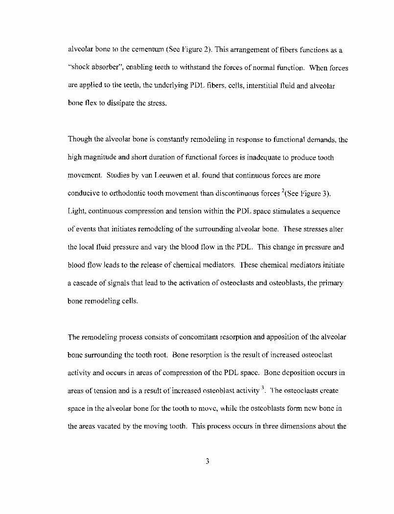
alveolar bone to the cementum (See Figure 2). This arrangement of fibers functions as a
"shock absorber", enabling teeth to withstand the forces of normal function. When forces
are applied to the teeth, the underlying PDL fibers, cells, interstitial fluid and alveolar
bone flex to dissipate the stress.
Though the alveolar bone is constantly remodeling in response to functional demands, the
high magnitude and short duration of functional forces is inadequate to produce tooth
movement. Studies by van Leeuwen et al. found that continuous forces are more
conducive to orthodontic tooth movement than discontinuous forces 2 ( ~ e e Figure 3).
Light, continuous compression and tension within the PDL space stimulates a sequence
of events that initiates remodeling of the surrounding alveolar bone. These stresses alter
the local fluid pressure and vary the blood flow in the PDL. This change in pressure and
blood flow leads to the release of chemical mediators. These chemical mediators initiate
a cascade of signals that lead to the activation of osteoclasts and osteoblasts, the primary
bone remodeling cells.
The remodeling process consists of concomitant resorption and apposition of the alveolar
bone surrounding the tooth root. Bone resorption is the result of increased osteoclast
activity and occurs in areas of compression of the PDL space. Bone deposition occurs in
areas of tension and is a result of increased osteoblast activity 3 . The osteoclasts create
space in the alveolar bone for the tooth to move, while the osteoblasts form new bone in
the areas vacated by the moving tooth. This process occurs in three dimensions about the

tooth root and is a product of the local and systemic biological factors, as well as the
magnitude, duration and direction of the externally applied force.
Biomechanics of Tooth Movement
The orthodontic appliance is designed to move teeth by applying a force system at a
distance from the center of resistance. For a free body, the center of resistance is
equivalent to the center of mass (See Figure 4). When a force is applied through the
center of resistance a free body will move linearly without rotation. Teeth, though, are
embedded in alveolar bone and restrained by the periodontal ligament. Hence, the center
of resistance is not analogous with the center of mass. In a healthy periodontium, the
center of resistance of a tooth is located below the crest of the alveolar bone. Proffit
states that its location can be estimated by taking a point halfway between the midpoint
of the embedded root and the crest of the alveolar bone 4. Burstone calculates the
location of the center of resistance of a single rooted tooth by multiplying the distance
between the root apex and alveolar crest by 0.33 5. As evident in both of these estimates,
the center of resistance is dependent on the root length, morphology and the level of the
alveolar bone (See Figure 5).
Any force applied at a distance from the center of resistance will produce a moment of
the force (MF )(See Figure 6) 6 . The moment of the force (MF ) can be calculated by
multiplying the force magnitude by the perpendicular distance from the center of
resistance, MF = Force x distance. This force system will produce simultaneous linear
and rotational movement. Variation of either the force magnitude or the distance from
the center of resistance can have a significant affect on the magnitude of MF.
4

Due to the center of resistance of the tooth being at a distance from the point of force
application, the orthodontic appliance must use couples to control tooth movement in
three dimensions. A couple, or pure moment, will produce pure rotation about the center
of resistance. A couple is defined as two parallel forces of equal magnitude acting in
opposite directions and separated by a distance '. Regardless of where the couple is
applied it will produce rotation about the center of resistance (See Figure 7). Couples are
often referred to as the applied moment. In the case of fixed orthodontic appliances,
these couples occur between the bracket and archwire and/or the ligature and the
archwire. As tooth movement occurs, couples serve to counteract moments of the
applied forces. The moment of the force will tend to rotate the crown in the direction of
force application, but couples within the bracket system function to offset the magnitude
of the moment of the force. By offsetting the moment of the force, these couples aid in
maintaining the orientation of the tooth as the center of resistance moves linearly.
We can predict tooth movement by combining the force, moment of the force, and
applied moment into an equivalent force system. This equivalent force system defines a
force system at the center of resistance that is equivalent to the force system being
applied at the bracket. As seen in Figure 8, the sum of the forces and moments are
replaced at the center of resistance. The net force is the vector sum of forces being
applied at the bracket, while the net moment is determined by adding the moment of the
force and the applied moment of the couple. The ratio of this net moment to the net force
(M/F) can be used to predict tooth movement and the center of rotation of the tooth 6".
5

There are four basic types of tooth movement: tipping, translation, root movement and
rotation. Each type of movement can be defined by its specific momentlforce ratio.
Tipping occurs when the center of rotation is apical to the center of resistance. There are
two types of tipping: controlled and uncontrolled (See Figure 9). Uncontrolled tipping
occurs when the ratio of the MIF 5 5: 1, which places the center of rotation between the
center of resistance and the root apex. Controlled tipping occurs when the ratio of the
M/F = 7: 1, which places the center of rotation at the root apex 6 . Controlled tipping
requires a couple to control for the moment of the force, while uncontrolled tipping can
occur without a compensating couple.
Translation, also known as "bodily movement", occurs when the center of rotation is
located at an infinite distance from the center of resistance (See Figure 10). Typically
this type of movement requires an MIF = 10: 1 6 . Translation can be achieved in two
ways. One is by applying a force through the center of resistance of the tooth, which can
be difficult because it is usually located below the crest of alveolar bone. The other is to
incorporate an applied moment that negates the moment of the force. In this situation
there is a net linear force through the center of resistance but no net rotation.
The third type of tooth movement is root movement. This occurs when the center of
rotation is located coronal to the center of resistance. Root movement requires an MIF L
12:l 6 . With this type of movement the root apex of the tooth will move a greater
distance than the crown (See Figure 10). Clinicians frequently refer to this root
movement as "torque".
6

The final type of movement is rotation. Pure rotation, which requires the absence of
linear movement of the center of resistance, occurs when the center of rotation is located
at the center of resistance. Pure rotation requires the presence of a couple. It cannot be
achieved through the combination of a moment and a force. Without an equal and
opposite force there will always be a linear effect on the center of resistance, therefore
producing translation in combination with the desired rotational movement (See Figure
11).
Fundamentals of Static Equilibrium
Static equilibrium implies that the sum of the forces and moments acting on a body is
zero. This concept is derived from Newton's three laws of motion. The first law, called
the Law of Inertia, states that a body at rest will remain at rest and a body in motion will
remain in motion unless acted upon by an external force. This means that a body at rest
is at rest because the sum of all forces acting on the body equals zero. The second law,
Law of Acceleration, deems that force is equal to mass times acceleration (F=ma) and
that a force will act to change motion in the direction that it acts. Newton's third law of
motion is the Law of Action and Reaction. This law states that to every action there is an
equal but opposite reaction. This third law is fundamental to orthodontic biomechanics
because it stresses that any force applied to achieve a desired outcome will have a
reactive force capable of an undesirable outcome.

When evaluating an orthodontic force system it must be assumed that all aspects of the
appliance are at rest. Therefore, the sum of the moments and forces acting on the
appliance must be equal to zero. This assumption makes it possible to calculate the
applied force system when there is adequate knowledge of some aspects of the system.
Because static equilibrium states that the sum of all forces equals zero (CF=O) and the
sum of all moments equals zero (CM=O), we can use formulations to calculate unknown
force values when certain values are known. For instance, if a mesial force of 100 grams
is applied to a canine bracket the tooth will tip until acted upon by another force. In this
case it occurs when the bracket engages the archwire. If we know the distance from the
bracket to the center of resistance of the canine is 10mm and the bracket width is 4mm
we can calculate the normal forces of the couple acting within the bracket slot (See
Figure 8).
Example Calculation:
Static Equilibrium: CF=O ; CM=O
MF (Moment of Force) = 1 00 grams x 1 0mm = 1000g-mm
Mc (Moment of Couple) = Fc (Normal Force of Couple) x 4mm
CM=O, therefore MF + MC = 0
1000g-mm + 4mm(Fc ) = 0
4mm(Fc ) = - 1000g-mm
Fc = -250 grams
Therefore, we know from this calculation that the archwire must be able to deliver 250
grams of force at the bracket archwire interface in order to offset the moment of the
external force of 100 grams. If we understand the force system produced by the
8
appliance in equilibrium we can more accurately predict the treatment response. This
understanding allows us to plan for the desired tooth movements, as well as make
compensations for the undesirable side effects.
The Fixed Orthodontic Appliance:
The orthodontic appliance we know today was introduced by Edward Angle in the late
1920's. Angle realized that by turning his Ribbon Arch appliance "edgewise", orienting
the long side of the rectangular archwire buccolingually, he could gain greater control
over root position 9. This Edgewise appliance was the first to use rectangular archwires
and a rectangular bracket slot. Angle's Edgewise appliance improved the ability of the
orthodontist to control tooth movement, but still required multiple archwire bends to
achieve ideal alignment, root angulation and torque.
In the 1980's, Larry Andrews introduced the Straight-wire appliance. Andrews'
appliance, by incorporating off-sets, root tip and torque in the bracket itself, reduced the
need for the excessive wire bending required by the Edgewise appliance lo. Though
Andrews' original prescription has been modified by many, the Straight-wire appliance
continues to be the instrument of choice for orthodontists. Due to many modifications of
Andrews' bracket prescription, this appliance is generically referred to as a preadjusted
appliance.
The typical preadjusted orthodontic appliance consists of three components; brackets,
archwires and ligatures. In the case of self ligating brackets, a ligature is not necessary
because a ligation mechanism is incorporated into the bracket face by the manufacturer.
Because of the role that couples play in controlling tooth movement, it is the interaction
of these components of the appliance that determine how the tooth will move relative to
its three planes of space. As in the original Edgewise appliance, the bracket's rectangular
slot allows for two points of contact in both the buccolingual and mesiodistal planes
when used in conjunction with a rectangular archwire. As mentioned previously, these
two points of contact create a couple, which aids in the three dimensional control of tooth
movement.
The archwire functions as a spring, storing energy to be delivered through the bracket to
direct tooth movement. In general, the archwire is the primary source of stored energy,
though auxiliary springs and elastics may also be used. Its physical properties dictate the
magnitude and duration of force that will be delivered to the dentition. The ligature's
roles are to keep the archwire fully seated in the bracket slot, to maintain the contact
points between the bracket slot and archwire and to provide the buccolingual couple
required for first order control. Ideally, the ligature will deflect and activate the archwire
"spring" while limiting the dissipation of energy as it is transferred from the archwire to
the tooth. Variations in any of these three components may alter the nature of the force
system being applied to the supportive structures of the teeth.
According to Burstone, the optimal orthodontic appliance has three main characteristics:
1) Accurate control of the center of rotation during tooth movement. 2) Optimal stress
levels in the periodontal ligament. 3) Constant level of stress during tooth movement '. The first, control of the center of rotation, is determined by the ratio of the moment to the
force (M/F) 6 3 8 5 " . The orthodontic appliance must provide a means for producing a
couple in order to control for the moment of the force that is being applied at the bracket.
As described previously, the relative magnitude of these two variables, the moment and
the force, affects the location of the center of rotation. Tipping, translation and root
movement are three types of tooth movement that can be achieved through variations in
the M/F ratio 7.
The second characteristic of an orthodontic appliance is the ability to apply an optimal
stress level in the PDL. This is best achieved by using materials with a low load-
deflection rate. The load-deflection rate is a measurement of how a spring's resistance or
force delivery changes over a distance of activation. A low load-deflection rate is most
desirable for orthodontic tooth movement because the force level will remain relatively
constant as the degree of deflection becomes less. For example, as crowded teeth begin
to align, archwire deflections become less severe and force levels decrease. If force
levels decreased significantly with a small change in wire activation, tooth movement
would slow or stop until the archwire was changed and an adequate force level was
regained. Instead, with a low load-deflection rate, force levels remain relatively constant
and tooth movement continues as the teeth align.

Also, low load-deflection archwires allow for greater accuracy in controlling force
magnitudes. A small error in the deflection of an archwire with a high load-deflection
rate will result in a large increase or decrease in force magnitude. This could result in
either improper tooth movement or unwanted side effects. Conversely, a low load-
deflection archwire provides a larger range of deflection that will produce relatively small
variations in the applied force.
The third important characteristic of an orthodontic appliance is the maximal elastic load,
which is the greatest force that can be applied without causing permanent deformation.
Tooth movements and archwire activations should occur well below this maximal elastic
load. The greater the maximal elastic load, the greater the range the archwire may be
deflected without risking deformation or breakage. When an appliance has a low
maximal elastic load it is at greater risk for plastic deformation or breakage, which means
there is a greater risk of inefficient and/or unwanted tooth movement '.
Orthodontic Treatment Sequence
In orthodontics, tooth movement is defined relative to its three planes of space.
Movements in these planes are categorized as first order, second order and third order.
First order tooth movement, commonly thought of as "in/outm, refers to movements that
can be viewed from the occlusal perspective. These include buccolingual or labiolingual
movements, as well as rotations about the long axis (coronal-apical) of the tooth. Second
order movements, referred to as "tipping", can be viewed from the buccolingual

perspective. These include movements in an occlusogingival direction or rotation about a
buccolingual axis. Rotation about this axis would result in tipping of the root or crown in
a mesial or distal direction. Finally, third order movement, commonly thought of as
"torque", can be viewed from a mesiodistal perspective or buccolingual crossection.
Third order refers to movement about a mesiodistal axis. This movement is important
when attempting to achieve proper incisor inclination.
These three types of tooth movement are achieved through interaction of the archwire
with the bracket slot and ligature. In the case of first order movement, the couple is
generated when two points of contact occur between the bracket slot and archwire andlor
the archwire and ligature. Because the force of ligation occurs only in a buccolingual
direction, second order and third order movements are limited to interactions between the
bracket slot and archwire (See Figure 12). Second order couples are formed when the
archwire engages the bracket slot at a mesial and distal contact point, while third order
couples have contact points that are oriented buccal and lingual.
Orthodontic treatment typically follows a sequence of correction through these three
orders of tooth movement. The initial phase of orthodontic treatment, alignment, focuses
on first order movements. During this phase, archwires with low load-deflection rates
and large elastic ranges are used because they allow for the delivery of low constant
forces over a wide range of movement. To deliver an adequate force system, the
clinician selects an archwire dimension and material that can be easily deflected, fully

ligated in the bracket slot and delivers a low constant force over a large range of
activation.
The second phase involves second order movements such as leveling and root tip.
Leveling, or occlusogingival movements, can be accomplished using the force systems
generated during the initial phase, but root tip requires increased stiffness of the archwire
in order to deliver an adequate applied moment. To achieve the necessary intrabracket
couple, the archwire must be of adequate dimension to engage the mesial and distal
corners of the bracket slot. Once the necessary dimension is selected the clinician can
dictate the force level and load-deflection rate by varying the archwire material.
The final phase of treatment, third order correction, involves the full expression of the
prescription determined by the preadjusted appliance. To fully express the prescription
and engage the third order couple, the archwire's dimension must approximate that of the
bracket slot. By filling the bracket slot with a full size archwire, the clinician can assure
that all couples will be engaged and any remaining correction will be resolved. Also,
because the buccolingual dimension of the bracket, 0.028", is approximately four times
smaller than the mesiodistal dimension, 0.138", the archwire must be of sufficient
stiffness to deliver the higher force values necessary for an adequate third order couple
(See Figure 12).

Orthodontic Archwires
Archwire Properties
There are many properties of archwires that are to be considered when selecting one for
treatment. As previously discussed, the phase of treatment and order of tooth movement
will dictate the desirability of certain properties. Therefore, the clinician should
understand how variations in archwire material and dimension can affect the efficiency
and performance of the preadjusted appliance.
Primarily, clinicians use three different wire materials during the course of orthodontic
treatment. They are stainless steel, nickel titanium and beta titanium. These three
materials are available in all dimensions of orthodontic archwires, including round,
square and rectangular crossections. These wires can vary in dimension from 0.012"
diameter round wire to 0.022" x 0.028" rectangular wire. Though they are available in
the same dimensions and crossections, stainless steel, nickel titanium and beta titanium
each has unique physical properties that make it better suited for specific phases of
treatment.
Several factors are important when choosing an archwire. Kapila defined seven
characteristics that he considered to have the most clinical relevance. These
characteristics are: 1) Springback or working range 2) Stiffness or load deflection rate 3)
Formability 4) Modulus of resilience or stored energy 5) Biocompatibility 6) Joinability
and 7) Friction 1 2 .

Springback
Springback, or working range, is related to the ratio of the yield strength to the modulus
of elasticity (YSIE). A greater working range allows for larger activations, resulting in an
increased working time for the appliance. It is also a measure of the elastic limit, or how
far a wire can be deflected before experiencing permanent deformation I2(see Figure 13).
Nickel titanium has physical properties that provide it the largest working range of the
three materials 1 3 . When compared to stainless steel, beta titanium wire can be deflected
twice as much without permanently deforming 14.
Load Deflection
Another characteristic is the load deflection rate, or stiffness of the wire. This is the force
delivered by an appliance over a given range of deflection, and is proportional to its
modulus of elasticity 12,'5. The modulus of elasticity is determined by calculating the
slope of the elastic region of the load deflection curve (See Figure 13). A low load
deflection rate is beneficial for the early phases of orthodontic treatment because it
provides lower forces, more constant forces and greater accuracy in the application of
force. Nickel titanium wires display the lowest load deflection rates, followed by beta
titanium and then stainless steel 13,16,17
Modulus of Resilience
The modulus of resilience is the amount of energy stored in the wire. It corresponds to
the area under the curve for the elastic range of the wire. This is an important value

because it determines the amount of work available to move teeth. When the bending
angle or torsional moment is the same for the three wire materials, the nickel titanium
wire shows the greatest amount of stored energy, followed by beta titanium and then
stainless steel (See Figure 14). This increased energy should result in increased clinical
efficiency by decreasing the number of archwire changes and therefore the number of
visits l33I6.
The Nj.cke1 Titanium Archwire
Nickel titanium alloys were first introduced to orthodontics by Andreasen in 1971 1 8 .
This alloy, referred to as Nitinol, was developed by Buehler at the Naval Ordinance Lab
in the early 1960's. It was the first "shape memory" alloy and gained wide acceptance in
orthodontics due to its high springback and low stiffness l 6 (See Figure 15). In 1985,
Burstone introduced Chinese NiTi, another nickel titanium alloy. This new alloy had 1.6
times the springback, 36% the stiffness and less permanent deformation when compared
to Nitinol l 7 (See Figure 16).
Physical Properties of Nickel Titanium
Ideally, a nickel titanium wire should retain its shape at intraoral temperature but be
formable at a lower room temperature. This property gives the clinician the ability to
ligate the archwire into the bracket with relatively little effort, but have it regain shape
upon unloading at higher intraoral temperatures. During this shape regaining, the
archwire is applying light, continuous force to the dentoalveolar structures. According to

Andreasen and Morrow, nickel titanium provides many advantages for the patient and the
clinician. These advantages include fewer wire changes, less chairside time, reduced
time to align and level and less patient discomfort 1 6 . The properties of nickel titanium
alloys responsible for these clinical advantages are shape memory, superelasticity and
hysteresis.
Shape Memory
Andreasen and Morrow described "Shape memory" as the ability of a wire to return to a
previously manufactured shape when heated through a transition temperature range
(TTR) l 6 (See Figure 17A). Below its TTR the wire can be significantly deformed, but
once heated the wire quickly returns to its original manufactured form. At low
temperatures, below the martensitic finish temperature (Mf), nickel titanium alloys exist
only in the martensitic phase. As the temperature increases, the alloy begins to convert
from martensite into austenite. Once the temperature surpasses the austenitic finish
temperature (Af) for the alloy, the material has completely transformed into its austenitic
phase and returned to its programmed shape. In the absence of localized mechanical
stress, an archwire that is 100% austenitic is no longer superelastic.
The change from a deformed shape to the "memorized" form involves a transformation
from the martensitic phase to the austenitic phase. This phase change occurs as an actual
shift in the crystal structure of the alloy without changing the molecular structure. In
order for this shape memory effect to occur intraorally, the alloy's austenitic finish (Af)
temperature needs to be set below oral temperatures. This is because the alloy is
18

manufactured to regain shape only once it has surpassed its Af. The nickel titanium alloy
loses much of its superelasticity when it exists purely in the austenitic form 19. Therefore,
the shape memory property of nickel titanium is not correlated with its superelasticity,
but instead is another outcome of the alloy's uniquely flexible crystalline structure.
Superelasticity
Superelasticity, or pseudoelasticity, refers to nickel titanium's ability to return to its
original form upon unloading after a significant deflection. This property is related to the
transformation between distinct crystal structures. Nickel titanium can exist in three
forms: martensite, austenite and stress-induced martensite. In response to temperature or
mechanical stress the crystal structure is modified without a change in the atomic
composition. Unlike that seen in other metal alloys, this stress related transformation
from austenite to martensite is reversible. In the martensitic phase the alloy displays
decreased stiffness, decreased springback and increased formability. The austenitic
properties vary from those of the martensitic phase by providing increased stiffness,
increased springback and reduced formability. Stress-induced martensite displays the
superelastic properties, with a low modulus of elasticity and large working range (See
Figure 17B).
Phase transformation of the nickel titanium alloy can occur in response to both
temperature and mechanical stress. As an archwire is deflected the alloy undergoes a
local phase transformation from austenite to martensite only at the point of high stress
bending. This transformed phase is referred to as stress-induced martensite. Even if the
19

alloy is at a temperature above its Af, localized stress can induce the phase transformation
to occur. The local transformation to stress-induced martensite results in decreased
stiffness and increased formability, therefore allowing the clinician to easily overcome
large deflections during archwire ligation.
It is between the Mf and Af that the superelastic properties of nickel titanium alloys are
most apparent. This atomic equilibrium gives the crystal lattice a better ability to absorb
stress. This results in a reduction of the modulus of elasticity, which means a lower load
deflection rate. As a general rule, the austenitic phase of a superelastic wire will be
stiffer than the martensitic phase, but both will be stiffer than a superelastic wire in phase
transformation 19.
Hysteresis
The temperature required to transform martensite to austenite is slightly higher than that
to transform from austenite back to martensite (See Figure 17A). This difference in
transformation temperatures is referred to as hysteresis. Hysteresis also occurs during the
stress-induced transformation from austenite to martensite 20 (See Figure 18). This
means that the force required to deflect and ligate the archwire is greater than the force
being delivered to the dentition upon unloading. Reducing the stress hysteresis means
reducing the differential between the loading and unloading forces of the archwire. It has
been suggested by Liaw et al. that reducing the stress hysteresis of an archwire could lead
to a more favorable delivery of force in the clinical situation 21.

Orthodontic Archwire Ligation
According to Harradine, an ideal ligation system will have the following properties: 1) Be
secure and robust. 2) Ensure full engagement of the archwire. 3) Be quick and easy to
use. 4) Assist good oral hygiene. 5) Be comfortable for the patient. 6) Allow the clinician
to incorporate high and low friction as desired. 7) Permit easy attachment of auxiliaries
22. These properties focus on decreasing chairside and overall treatment time, improving
patient acceptance and efficiently transmitting forces from archwire alloys.
Elastomeric and Wire Ligatures
Until the introduction of elastomeric modules in the 1970's, individual wire ligatures
were routinely used to ligate archwires. These steel ligatures required that the clinician
place, tighten, cut and then cinch the ligature on every tooth. Due to this time consuming
process, elastomerics quickly replaced wire ligatures as the method of choice.
Elastomerics are much faster and easier to place and more comfortable for the patient.
They can also be fashioned into chains for space closure, as well as manufactured in
various colors to improve patient acceptance. In relation to wire ligatures, the
disadvantages of elastomerics include increased microbial colonization, incomplete
seating of archwires for rotational control, rapid force decay, permanent deformation and
increased resistance to sliding 23,24.
Taloumis reported that elastomerics lose 53% to 68% of their ligation force within the
first 24 hours of activation. He also found that a simulated oral environment, one that is

warm and moist, lead to a more pronounced force decay and permanent deformation of
the activated elastomeric 24 (See Figures 19-20). The uptake of water in the oral
environment facilitates the slippage of molecules and increases the rate of force decay 25.
Self-Ligating Brackets
Due to these shortcomings of elastomerics, orthodontists have sought a ligation method
that is as fast, easy and comfortable as elastomerics, but has the force constancy,
improved cleansability and lack of deformation of wire ligatures. These brackets have
become known as self-ligating brackets and have gained considerable popularity over the
past fifteen years. It has been suggested that self-ligating brackets reduce chairside time,
allow for longer appointment intervals due to consistent wire activation, provide better
access for patient hygiene and reduce overall treatment time 26P. The reported
disadvantages of self-ligating brackets include increased cost, reduced control of tooth
movement, increased buccolingual profile, opening or breakage of ligation mechanisms
and a tendency for archwire slippage resulting in tissue trauma 22.
Though they were first introduced to orthodontics in the 1930's' self-ligating brackets did
not gain acceptance until the 1980's. Due to high manufacturing costs and poor
acceptance, the early designs were quickly abandoned. Not until the early 1970's did
self-ligating brackets return to orthodontics. The EdgelokB bracket was the first to be
commercially available on a wide scale. The EdgelokB was a passive self-ligating
bracket, but only achieved limited acceptance among orthodontists. In the early 1980's'
another self-ligating bracket was introduced that incorporated an active ligation

mechanism. This bracket, called SPEED@, used a spring clip that interacted with the
archwire. Since then many different self-ligating brackets have come onto the market.
Commercially available self-ligating brackets can be differentiated as having either an
active or passive ligation mechanism.
Active and Passive Ligation
Active SLBs (ASLBs) incorporate a clip that invades the bracket slot. This clip is able to
flex and therefore can apply a seating force to the archwire. The force applied to the
archwire varies with the archwire dimension and the first-order position of the tooth.
Because the clip is not in constant contact with the archwire, these mechanisms have
been referred to as interactive. 28 This is to differentiate them from conventional ligation
brackets (CLBs) that use elastomeric and wire ligatures to provide a constant seating
force, independent of wire size or bracket position. Examples of ASLBs currently on the
market are the In-Ovation R@ (GAC Intl), SPEED@ (Strite) and Time@ (American
Orthodontics) brackets (See Figure 21).
Passive self-ligating brackets (PSLBs) have a rigid component that entraps the wire in the
bracket slot without applying a force. With PSLBs, the archwire only engages the
ligation mechanism when the wire is of adequate buccolingual dimension or the tooth is
28-33 sufficiently malpositioned in the first-order. Examples of PSLBs currently on the
market are the Damon Mx@ (Ormco), CarriereB (Class One) and the SmartClipB (3M
Unitek) brackets (See Figure 22).

Friction in Orthodontics
Definition of Friction
Friction is defined as the force that resists movement of one surface past another and acts
in a direction opposite the direction of movement 34. There are two main components that
influence the magnitude of the force of friction ( F F ~ ) . The first is the normal force (FN),
which is the perpendicular force responsible for holding the two surfaces in contact. The
second is the coefficient of friction (y), which is an experimentally derived constant
dependent upon the surface characteristics of the materials in contact. The coefficient of
friction exists as both a static (y,) and kinetic (pk) value. The static coefficient (p,)
pertains when calculating the force required to initiate movement, while the kinetic
coefficient (pk) is used once the surfaces are in motion. The coefficient of friction is
calculated by dividing the force of friction (FFR) by the normal force (FN). Hence, the
force of friction is described mathematically by the equation FFR= FN p.
In orthodontics, the moving surfaces in contact are the brackets, archwires and ligatures.
These components of the fixed appliance initiate tooth movement by transmitting force
from the archwire to the periodontal support of the tooth. As the tooth moves, the
bracket, archwire and ligature are intermittently contacting and sliding against one
another. When using a conventional preadjusted appliance, these surfaces must move
past each other in order for tooth movement to occur. Because friction acts to dissipate
the magnitude of force transmitted from the appliance to the teeth, many studies have
been designed to measure and better understand the role that friction plays in
orthodontics and how variations in the three appliance components affect the delivery of
force. Most studies have used in vitro models to vary the components of the fixed
appliance. The brackets, archwires and ligatures have been varied in the following ways:
material, dimension, ligation method, bracket angulation, relative motion and biological
resistance. From these studies we have learned much about the interaction of these
components and how each plays a role in determining the magnitude of frictional
resistance.
Material Composition
The influence of material composition on friction can be divided into two categories:
surface characteristics and mechanical properties. Angolkar, when sliding an archwire
through parallel bracket slots, reported that ceramic brackets exhibit more resistance to
sliding than stainless steel brackets 35. Angolkar and Bednar both propose this is due to
the increased surface irregularities of ceramics. Magnification shows the ceramic surface
to have a highly variegated topography, which leads to a higher coefficient of friction and
greater frictional resistance when compared to stainless steel 29,35-38
With regards to archwire material, most authors agree that stainless steel archwires
generate less frictional resistance when compared to nickel titanium and beta titanium,
with the beta titanium alloy showing the highest levels of resistance 3 1,36,39-42 . Beta
titanium, at 80% titanium, has a higher coefficient of friction due to a more reactive
surface chemistry than nickel titanium at 50% titanium. Kusy reported that the higher the
percent composition of titanium the greater the surface reactivity, and subsequently the
25

greater the frictional resistance 43. Tidy's study of sliding frictional resistance found that
nickel titanium wires have twice and beta titanium five times the frictional resistance of
stainless steel 42.
Conversely, some investigators have shown variations in frictional resistance when alloys
are subjected to second order binding forces 44345. Frank and Nikolai's findings showed
nickel titanium to have less frictional resistance than stainless steel when second order
angulation exceeded a certain limit 44. This limit of angulation was defined by Kusy and
Whitley in 1999 as the critical contact angle. It refers to the degree of bracket angulation
required for the wire to engage mesial and distal contact points within the bracket slot 46
(See Figure 26). When second order angulations exceeded this critical contact angle,
binding and increased frictional values were seen. Both Frank and Nikolai 44 and
Thorstenson and Kusy 45 reported that the nickel titanium alloy showed less frictional
resistance than the stiffer stainless steel. Frank and Nikolai proposed that this was due to
nickel titanium's low load deflection rate, which results in a lower normal force within
the bracket slot, and thus a lower force of friction 44.
Though the frictional resistance was found to be less with nickel titanium archwires, this
should not be taken to mean that nickel titanium is the preferred material during sliding
mechanics. In the clinical situation, a reduced resistance to sliding is believed to be
preferential, but an adequately stiff archwire that provides the uprighting moment
required for controlled tooth movement is significantly more important.

Material Dimension
Multiple studies have assessed the effect of varying the size and shape of brackets and
archwires on frictional resistance. When considering archwire shape and dimension,
most authors agree that friction increases with the cross-sectional area of the archwire
29,35,40,41,47,48 . Some researchers have reported a deviation from these findings, which they
propose is a result of wire notching during increased second order angulation 444.6.
Frank and Nikolai described this notching phenomenon by considering variations in
pressure at the contact points between the archwire and bracket. Pressure is calculated
by dividing the applied force by the surface area of application, P = FIA. Frank and
Nikolai proposed that round wires will contact the bracket slot at a single point resulting
in a higher pressure due to the decreased surface area. Conversely, rectangular wires
contact the bracket slot over a line, which increases the surface area in contact and
therefore decreases the pressure. It is suggested that high pressure at a point contact can
result in increased notching of the round wires and a subsequent increase in resistance to
sliding 44.
Bracket width has been shown to affect frictional resistance in multiple ways, but there is
controversy as to whether it increases or decreases friction. Some authors suggest that
increased bracket width decreases the force of friction by decreasing the interbracket
distance. This results in increased stiffness of the wire segment, which leads to decreased
bending and a decreased risk of binding297400."2. Conversely, a stiffer wire segment would
mean a greater load for an equivalent degree of deflection. This greater load would result

in larger normal forces within the bracket slot, which could translate into an increase in
frictional resistance.
Also, the geometry of the bracket slot shows that second order binding occurs at smaller
angulations for wider brackets when comparing them to more narrow ones. This means
that wider brackets require less tipping, in either first or second order dimensions, for the
archwire to engage the slot and generate a couple. Frank and Nikolai suggested that this
earlier binding resulted in an increased normal force and therefore an increased frictional
resistance for wider brackets44. Kapila et al. and Ogata et al. both suggest that increased
bracket width increases friction by increasing the activation force necessary to place an
elastomeric ligature. This increased elastomeric activation results in an increased normal
force and therefore increased force of friction 24,4 1,49
Bracket Ligation
Due to its direct effect on the normal force, the method of ligation may have the most
significant effect on frictional resistance. Ligation techniques can be divided into three
categories: active, interactive and passive. Active ligatures have mechanical properties
that allow them to apply a force to the archwire in order to hold it in the bracket slot.
Active ligatures may be elastomeric rings or stainless steel ligatures. Interactive ligation,
as defined by Voudouris, consists of a precision arm that extends into the bracket slot2'.
The precision arm interacts and applies a force to the archwire under two circumstances:
(1) the archwire is of significant buccolingual dimension to contact the arm or (2) the
bracketed tooth is sufficiently malpositioned. Passive ligatures function by converting
2 8

the bracket slot to a tube. The passive ligature restrains the archwire within the bracket
slot, but the ligature has no mechanical properties that allow it to function as a spring or
apply a force to the archwire.
Due to their ease of placement, low cost and patient acceptance, elastomerics have been
the ligature of choice for many years. As previously mentioned, the disadvantages of
elastomerics are stress relaxation, bacterial plaque accumulation and breakdown in the
oral environment 24.25,50 . Stainless steel ligatures provide a more constant force and
reduced plaque accumulation, but they require more time to place and their ligation force
can vary significantly depending on the clinician's technique 23,24,5 1 . Whether using
elastomeric or stainless steel ligatures, it has been estimated that the force of ligation can
range from 50 to 300 grams 40.44,47,52
In the case of self-ligating brackets, the ligation force varies with the type of mechanism
and the position of the bracketed tooth. When teeth are ideally aligned, passive systems
apply no ligation force, while the ligation force of active and interactive systems varies
with the archwire dimension. In the presence of malaligned teeth, ligation force will vary
with the degree of malposition, the ligation mechanism and the mechanical properties of
the ligated archwire.
The equation to calculate the force of friction, FFR= FN p, shows that an increase in the
normal force (FN), in our case the force of ligation, results in a proportional increase in
frictional resistance (FFR). Therefore, any ligation technique that applies a force to the
2 9

archwire should inherently produce more frictional resistance. When comparing the
frictional properties of active, interactive and passive ligation methods, studies generally
support this relationship.
Henao and Kusy, using a pretreatment typodont model, reported that passive self-ligating
brackets produced less frictional resistance when compared to conventional active
ligation. While a significant difference was seen during sliding of small diameter
archwires, Henao and Kusy showed no statistical significance as the wire size increased
to engage the self-ligating mechanism53354. Voudouris and Pizzoni et al., using a parallel
fixed bracket model, both showed PSLBs produced significantly less frictional resistance
than both CLBs and ASLBs. They also confirmed that self-ligating brackets in general
reduced sliding frictional resistance when compared to conventional ligation techniques
28.3 1
The methods of these studies must be questioned when evaluating the authors'
conclusions. The Henao and Kusy studies measured friction by pulling a ligated archwire
through brackets bonded to a pre-treatment typodont. Though this test measures friction
related to a wire moving through brackets, what does it suggest of the clinical situation
and the ability of the various ligation mechanisms to efficiently move teeth? There is an
assumption that a reduction in friction translates into more efficient tooth movement, but
as discussed previously, controlled tooth movement requires a force and an applied
moment. Obviously, there is more play present in a passive ligation mechanism, which
translates into a lower normal force and reduced resistance to sliding. The failure of the
30

ligature to fully seat and activate the archwire may reduce friction, but it also reduces the
ability of the archwire to provide an adequate force system for efficient tooth movement.
Pulling an archwire through ligated brackets allows us to measure frictional resistance,
but any assumptions regarding the clinical implications of these findings would be
misleading.
Clinical Studies
In 2005 and 2006 Miles reported two prospective clinical trials that used a split mouth
design to compare the effectiveness of passive self-ligating brackets to conventional twin
brackets. A baseline irregularity index was determined for each patient's mandibular
arch and then remeasured at each of two 10 week intervals. A 0.0 14" Damon copper
NiTi wire (Ormco) was activated for the first ten weeks and then replaced by a 0.0 16" x
0.025'' Damon copper NiTi (Ormco) for the second ten weeks of alignment.
Miles reported that neither the Damon 2 nor the SmartClip passive self-ligating brackets
were more effective at reducing irregularity than the conventional twin bracket with
elastomeric ligation. In the Damon 2 study the conventional twin bracket achieved a
lower irregularity index at both 10 and 20 weeks of alignment, but this value was not
statistically significant ". In the SmartClip study the conventional brackets showed a
statistically significant reduction in irregularity at 10 weeks, but at 20 weeks there was no
significant difference between the two groups 56.

For the Darnon 2 study Miles also measured patient comfort with the appliances. During
initial alignment the Damon 2 bracket was less painful, but when the larger archwire was
ligated at 10 weeks it was found to be more painful that the conventional ligation. This is
likely due to remaining irregularities requiring significant deflection of a rectangular
archwire. Due to its greater cross-sectional area, the rectangular archwire exhibits a
greater unloading force. Because the passive ligation mechanism does not allow for any
flexure or force dissipation, the patient feels more force and therefore more discomfort
following ligation 5 5 .
In another prospective study reported in 2007, Miles compared the rates of tooth
movement with SmartClip passive self-ligating brackets to conventional twin brackets
during en masse space closure. All anterior teeth were bonded with the same
conventional twin brackets. Each patient had SmartClip brackets bonded to second
premolars and molars on one side and conventional twin brackets on the other. The
patient was blinded according to the type of ligation. Space closure was accomplished
with a 0.0 16" x 0.022" stainless steel archwire, nickel titanium coil springs and stainless
steel ligation of the posterior conventional twin brackets.
Miles showed no significant difference in the rate of space closure between the passive
self-ligating and conventional twin tied with stainless steel ligatures. Teeth on the
SmartClip side moved at a median rate of 1. lmm per month, while teeth on the
conventional side moved 1.2mm per month. This study suggests that passive ligation

may not provide a significant clinical advantage over conventional ligation during en
masse space closure 57.
These clinical studies imply that friction may not be an overwhelming factor with regard
to the efficiency of tooth movement. In fact, Braun suggests that the "jiggling" effect of
teeth within the PDL renders friction inconsequential in the clinical setting.58 Therefore,
there may be other factors influencing the bracket-archwire interaction that may affect
treatment efficiency. We hypothesize that the interaction of the archwire and ligation
mechanism affects force delivery in the first order, and that understanding how archwire
selection can influence force delivery can enhance treatment efficiency.

Hypothesis
1. Degree of bracket play varies with the ligation mechanism and archwire diameter.
a. PSLBs exhibit greater bracket play than ASLBs and CLBs.
2. Deactivation force varies with the ligation mechanism and archwire diameter.
a. Using a Cantilever Test, CLBs and ASLBs will deliver higher deactivation
forces than PSLBs because of the active nature of the ligation mechanism.
b. Using a Three Point Bend Test, SLBs will return higher deactivation
forces than CLBs because SLBs will reduce frictional resistance and result
in less dissipation of the deactivation force.
3. Superelastic range varies with the ligation mechanism and archwire diameter.

1. To measure the degree of archwire deflection required for the ligation mechanism
to engage the first order couple when bracket type and wire diameter are varied.
2. To measure the force of deactivation produced by CLBs, ASLBs and PSLBs
while varying the degree of first order deflection and archwire diameter.
3. To examine the effect of ligation on the superelastic range by varying bracket
type, archwire diameter and the degree of deflection.

Materials and Methods
Brackets and Wires Tested
We evaluated five different orthodontic brackets: victoryTM (3M Unitek, St. Paul, MN),
smartclipTM (3M Unitek, St. Paul, MN), ~ n ~ v a t i o n - ~ ~ ~ (GAC Intl., Bohemia, NY),
Damon M X ~ ~ (Ormco, Glendora, CA), and carriereTM (Class One, Lubbock, TX). We
chose these brackets because each uses a different method for ligating the archwire into
the bracket slot. For ease of study we chose to limit our testing to maxillary premolar
brackets with an occlusogingival slot dimension of 0.022". See Table 1 for a description
of the various brackets' materials, dimensions and ligation mechanisms. In combination
with these orthodontic brackets, four superelastic nickel titanium archwire segments were
tested. The samples tested varied only in diameter and were obtained from the same
manufacturer (Ultimate Wireforms, Inc., Bristol, CT). See Table 2 for a list of the
archwires tested.
Table I: Description of Brackets Tested
Manufacturer
3 M Unitek
-- 3M Unitek
Clips 1 NiTi Clips I
~ a v r i e r e ~ '
1 In-Ovation R~
Effective Width*
3.73mm
Slot Width
2.98mm
4.15mm
Bracket TY pe
~'ictory'~'
~ r n a r t ~ i i p ~ ~
Damon MYm 1 Passive I 2.67mm I 2.39mm StainlessSteel 1 Ormco
Clip
Material
Stainless Steel
Ligation Mechanism
Conventional Elastomeric ---
Passive
Slide Passive
Slide Interactive
1 Elgiloy Door 1
(, Stainless Steel
* Distance between the contact points formed during a first-order couple. Varies with the width of the slot base and the ligation mechanism.
3.35mm
2.97mm
2.84mm
2.97mm
Stainless Steel
Stainless Steel
Ortho Organizers
GAC Intl.
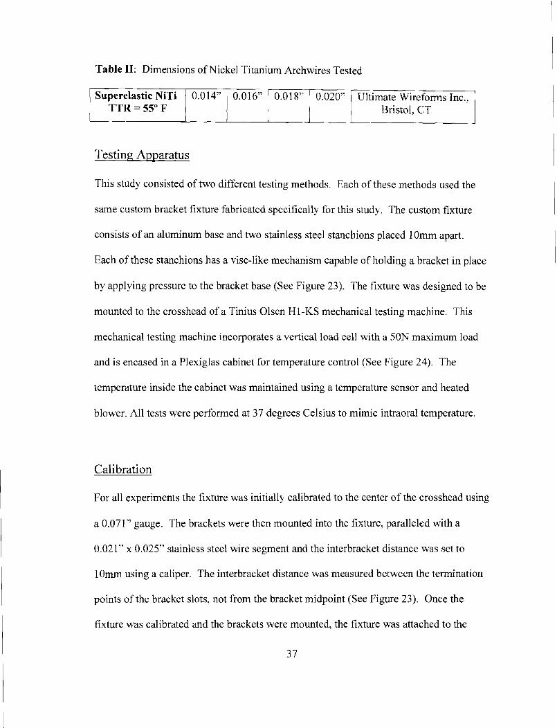
Table 11: Dimensions of Nickel Titanium Archwires Tested
Testing Apparatus
Superelastic NiTi TTR = 55" F
This study consisted of two different testing methods. Each of these methods used the
same custom bracket fixture fabricated specifically for this study. The custom fixture
consists of an aluminum base and two stainless steel stanchions placed 1 Omm apart.
Each of these stanchions has a vise-like mechanism capable of holding a bracket in place
0.014"
by applying pressure to the bracket base (See Figure 23). The fixture was designed to be
mounted to the crosshead of a Tinius Olsen H 1 -KS mechanical testing machine. This
mechanical testing machine incorporates a vertical load cell with a 50N maximum load
and is encased in a Plexiglas cabinet for temperature control (See Figure 24). The
temperature inside the cabinet was maintained using a temperature sensor and heated
blower. All tests were performed at 37 degrees Celsius to mimic intraoral temperature.
0.01 6"
Cali bration
For all experiments the fixture bras initially calibrated to the center of the crosshead using
a 0.071" gauge. The brackets were then mounted into the fixture, paralleled with a
0.021" x 0.025" stainless steel wire segment and the interbracket distance was set to
10mm using a caliper. The interbracket distance was measured between the termination
points of the bracket slots, not from the bracket midpoint (See Figure 23). Once the
fixture was calibrated and the brackets were mounted, the fixture was attached to the
3 7
0.01 8" 0.020" Ultimate Wireforms Inc., Bristol, CT
crosshead of the testing machine and approximated with the load cell carriage. A 0.021"
x 0.025" stainless steel wire segment was used to determine the zero position of the
crosshead. Zero position was defined as passive contact between the arch wire segment
and the load cell carriage. The tolerance for passivity was when the carriage and
archwire were in contact but measured less than 2 grams of force. Once the zero position
for the crosshead was set, testing of the brackets and archwire segments could begin.
Cantilevered Archwire Test
The first test uses a cantilever design to measure the interaction between the archwire and
bracket ligation mechanism. This design was chosen to limit the influence of sliding
frictional resistance on the measurement of the loading and unloading forces. A 1 Omm
straight segment of archwire obtained from the visually straight posterior segments of a
standard arch form is ligated in one bracket using the prescribed method. In the case of
the Victory bracket we used silver elastomeric rings from Class One Orthodontics (# 185-
58) and Mathieu pliers to place the elastomeric ligature. The archwire segment extended
5mm from the termination of the bracket slot to rest on the carriage of the load cell. Each
test consisted of the loading and unloading of the archwire segment in the buccal
direction over a range of 4mm at a rate of 1 Ommlmin.
Three Point Bending Test
The second test uses a three point bend design, similar to that commonly used for testing
the mechanical properties of orthodontic wires. In this test, the archwire segment is
ligated into both brackets, which are fixed at an interbracket distance of 1 Omm (See
3 8

Figure 23). The fixture and brackets are calibrated and mounted as previously described
in the cantilever test. Once the zero position is defined, a 20mrn straight archwire
segment obtained from the visually straight posterior segments of a standard arch form is
ligated into both brackets using the prescribed ligation method. As in the cantilever
study, we used silver elastomeric rings from Class One Orthodontics (#185-58) and
Mathieu pliers to ligate the archwire into the Victory bracket. The loading and unloading
of the wire occurred at the midpoint of the ligated brackets over a range of 4mm at a rate
of 1 Ommlmin.
Data Acquisition and Analysis
All combinations of brackets and archwires were tested three times with a new wire
segment used for each test. In the case of the Victory group, a new elastomeric ligature
was placed for each wire sample tested. Data was collected continuously at a sampling
rate of 20Hz in the form of ASCII files. These files were transferred to a Microsoft Excel
spreadsheet for processing and analysis.
Bracket play was defined as the amount of wire deflection required to initiate the first-
order couple. The degree of deflection required for bracketlarchwire contact was
measured at a threshold of 5 grams of loading force. The activation and deactivation
forces were measured continuously and the means * SD were calculated at lmm, 2mm
and 3mm of deactivation. The values for superelastic range were determined graphically
by selecting the end point for the superelastic plateau upon deactivation. The magnitude
of deflection at the end point was subtracted from the total 4mm deflection to calculate
3 9


Results
Cantilever Test
Figure 25 demonstrates a typical load deflection curve. As a reference, bracket play,
deactivation force and the superelastic range have been identified. Complete load-
deflection curves for the five brackets tested are seen in Figure 26A-D. The load-
deflection curves show that ligation type and archwire diameter have a significant effect
on the degree of bracket play, deactivation load and superelastic range.
Bracket Play
As seen in Table 111, the Victory bracket engaged the first-order couple at 0.57 0.004
degrees of wire deflection when paired with the 0.014" wire, followed by the In-Ovation
R (8.13 * 0.013 deg) and Smartclip (12.08 * 0.010 deg) brackets. The Damon MX
(14.66 0.029 deg) and Carriere (14.79 * 0.010 deg) brackets displayed the greatest
degree of bracket play and were not signiiicantly different from each other. As Figure 27
shows, trends remained intact during deflection of the 0.016", 0.018" and 0.020"
archwires, but the Victory bracket showed increased play with the 0.020" wire deflection.
The Damon MX and Carriere brackets were not significantly different for any wire
diameter tested and consistently showed the greatest amount of bracket play
Deactivation Force
The deactivation force varied with the ligation mechanism, degree of deflection and
archwire diameter. In Table IV, the mean loads at lmm, 2mm and 3mm of deactivation
4 1

are shown for the various bracket-archwire combinations. The Victory bracket varied
significantly from the SLBs for all archwire diameters at the lmm deflection (ps0.01).
As the degree of deflection increased to 2mm and 3mm, force values continued to vary
significantly between the Victory CLB and the other SLBs, but the mean force values
approximated each other in magnitude (See Figures 29 and 30). For all wire diameters
tested, PSLBs generally displayed lower deactivation forces when compared to the
Victory and In-Ovation R brackets. The one exception was when the Victory bracket
was paired with the 0.020" archwire. The 0.01 8" and 0.020" 3mm deflection showed the
Darnon MX (90.21 + 1.66g, 148.07 + 2.438) and Carriere (88.83 * 1.03 g, 148.05 +
0.77g) brackets to produce the lowest deactivation forces of all brackets tested (See
Figure 30).
As seen in Figure 28, Victory and In-Ovation R were the only brackets to produce a
measurable force with both archwires at lmm of deactivation. The Smartclip bracket
provided an unloading force with the 0.016" wire at Imm of deflection, while the Damon
MX and Carriere brackets produced no substantial force at I mm until the diameter was
increased to 0.020". For all archwire diameters and deflections tested, the Damon MX
and Carriere brackets were not statistically different (plO.O1).
Superelastic Range
As shown in Figure 3 1 , the superelastic range was significantly different for all brackets
except Damon MX and Carriere (p50.01). When coupled with the 0.014" archwire, the
Damon MX (1.77 * 0.02 mm) and Carriere (1.75 *0.02 mm) brackets provided the
42

smallest superelastic range and were not significantly different for any archwire diameter
tested. Table V lists the mean * SD values for all brackets and archwires tested. The
Victory (3.22 * 0.04 mm, 3.18 * 0.03mm, and 2.84 * 0.01 mm) bracket had the largest
superelastic range for the 0.014", 0.016" and 0.01 8" groups respectively. The
superelastic ranges for all PS1,Bs approximated each other as the wire diameter
increased. The In-Ovation R bracket had the largest superelastic range of all SLBs with
the 0.014" wire (2.21 * 0.01 mm): but the smallest when the wire diameter increased to
0.020" (2.06 h 0.02 mm). The superelastic range for the Victory (0.99 * 0.24mm)
bracket fell significantly when wire diameter increased to 0.02OV, while the PSLBs
showed an increasing superelastic range with increasing wire diameter.
Three Point Bend Test
Complete load-deflection curves for the five brackets tested are seen in Figure 32A-D.
The Smartclip bracket was not able to withstand the activation force when the 0.0 18"
and 0.020" wires were tested; therefore no data is available for these bracket-archwire
combinations. The load-deflection curves show that ligation type and archwire diameter
have a significant effect on the deactivation force. Because the three point bend test
requires that the archwire slides through the brackets, frictional resistance will influence
the measured forces of deactivation. All means i SD with statistical comparisons can be
found in Table VI.

1 mm Deflection
Figure 33 shows a comparison of the four wire diameters across all bracket types. For
the small diameter 0.014" wire, all SLBs exhibited similar forces levels and were
significantly lower than the Victory (1 5 1.82 * 2.41g) bracket. The SmartClip and In-
Ovation R brackets were not statistically significant, nor were the Damon MX or Carriere
different from each other. As wire diameter increased, the SLBs began to display greater
variation. The SmartClip and In-Ovation R brackets showed no significant difference.
but both were significantly different from the Damon MX and Carriere. The Victory
bracket continued to deliver the greatest deactivation force.
As stated previously, the SmartClip bracket was unable to hold larger diameter wires
during deflections of 3mm or greater. Therefore. no load-deflection data is available for
this bracket with the 0.018" or 0.020" archwires. When wire diameter increased to
0.01 8", the In-Ovation R (188.55 * 5.558) bracket provided a deactivation force that was
not significantly different from the Victory (1 8 1.76 * 4.24g). The Damon MX and
Carriere brackets continued to deliver lower deactivation forces with Damon MX (1 34.96
* 2.30g) significantly less than Carriere (152.00 i 6.47).
2mm Deflection
Figure 34 shows a comparison of all bracket types across the four wire diameters tested.
When testing smaller diameter wires, 0.01 4" and 0.0 16", all brackets delivered similar
force levels. Carriere (166.34 * 3.868) was the only bracket that was significantly
different with the 0.014" test. As wire diameter increased to 0.016", the Victory (196.04
44

* 7.09g) and In-Ovation R (209.03 * 7.61g) brackets delivered significantly lower
deactivation forces than the PSLBs. When the large diameter wires were tested there was
no statistically significant difference between the SLBs (p 5 0.01). The Victory (209.63
* 5.71g, 264.90 * 9.638) bracket returned significantly lower deactivation force than all
SLBs when coupled with 0.018" and 0.020" wire diameters.
3mm Deflection
Figure 35 shows a comparison of all bracket types across the four wire diameters tested.
The SmartClip (1 39.07 * 3.528) and Carriere (152.27 % 6.12g) brackets delivered the
greatest deactivation forces with the 0.0 14" deflection and were significantly different
than all other brackets. There was no statistically significant difference found with
deflection of the 0.016" wire. though the SmartClip (1 93.12 * 7.348) delivered the
highest force and Damon MX (160.87 * 15.27) delivered the lowest. When wire
diameter increased to 0.01 8" and O.O2O", the Damon MX and Carriere brackets
demonstrated the lowest dcactivation forces and were not significantly different from
each other.

Discussion
First order load-deflection curves were used to examine conventional (CLB), active self-
ligating (ASLB) and passive self-ligating (PSLB) bracket types. Cantilever and three
point bend models were developed to assess the bracket-archwire interaction. The
cantilever model assesses the pure force system occurring at the bracket by eliminating
the influence of sliding frictional resistance when measuring the activation~deactivation
load. The influence of friction is limited because the wire is not required to slide through
the bracket slot during deflection. A buccal deflection was chosen because it produces a
class I1 lever, which results in a greater force being applied to the ligation mechanism.
Conversely, the three point bend model requires that the wire slide through the brackets
during loading and unloading. This two bracket model comes closer to simulating the
clinical situation than the cantilever model, which was designed to focus specifically on
the force system at the bracket. Because the wire must slide through the brackets, this
test incorporates sliding frictional resistance into the load-deflection data. Results from
both the single bracket cantilever model and the two bracket three point bend model show
that the bracket type and archwire diameter have a significant effect on the degree of
bracket play, force of deactivation and superelastic range.
Authors generally agree that SLBs reduce sliding frictional resistance when in passive
alignment, but perform similarly to conventional ligation when archwire diameter andlor
angulation are increased to engage the bracket. 44,45,49,53,54,59-6 1 Due to the concerns of

anchorage loss with increased friction during sliding mechanic^"^", many studies have
focused on varying second order angulation while testing stiffer archwire materials of
greater cross-section. Until recently, little attention has been paid to the ligature-archwire
interaction during first order movement^"^^'. Because the ligation mechanism is inherent
in forming the first order couple that produces the axial moment, its interaction with the
archwire in the first order will have a significant effect on the tooth moving force.
Therefore, first order wire deflections should provide the best method for comparing the
ligation mechanisms of various bracket types.
Our results show that CLBs and ASLBs significantly reduce the degree of deflection
necessary to engage the first order couple, while narrow PSLBs like Damon MX and
Carriere exhibit the greatest amount of bracket play. Due to their ligation slides being
narrower than their slot bases, both Damon MX and Carriere brackets provide an
effective first order width that is less than the actual bracket width (See Table I). The
reduction in width results in a degree of first-order play that is greater than would be
expected with geometric calculations. Typically, wider brackets will engage the first
order couple earlier than more narrow brackets", but our data shows that the narrower In-
Ovation R bracket demonstrates less bracket play than the wider SmartClip. This is
likely a result of the interactive nature of the In-Ovation R ligation mechanism. Even
though In-Ovation R is smaller mesiodistally than SmartClip and Carriere, its ligation
clip engages the deflected archwire sooner.

When considering the correction of rotations, the degree of bracket play suggests how
much correction may be accomplished with a given bracket-archwire combination.
When tested with the larger 0.01 8" wire, the PSLBs provided a minimum of 9.13 degrees
of play. This means that correcting a tooth that is rotated less than 9 degrees would
require one of the following: a wire with increased buccolingual dimension, a wider
bracket or addition of a more active ligation mechanism. The In-Ovation R bracket had
only 8.13 h 0.013 degrees of bracket play with the 0.014" wire, which is less than the
PSLBs even when coupled with the larger 0.01 8" wire. The conventional Victory
bracket showed the smallest degree of bracket play, but this test did not take into account
the force decay of the elastomeric. Taloumis reported that elastomerics lose 53% to 68%
of their ligation force in the first 24 hours of a ~ t i v a t i o n . ~ ~ Therefore, bracket play can be
expected to increase over time for the CLB. Although, the use of small diameter, low
force wires with the CLBs would limit the risk of the deflected wire overwhelming the
elastomeric.
Once the first-order couple is engaged, the PSLBs demonstrated lower deactivation
forces compared to the Victory and In-Ovation R brackets. This is due to the passive
nature of the ligation mechanism. As the deflected archwire is returning to its passive
state, the unloading force of the archwire and force of the active ligation mechanism
(elastomeric or self-ligating clip) combine to produce a deactivation force that is greater
than that of the PSLBs.

Interestingly, no PSLBs were able to provide a measurable force with a 1 mm deflection
of the 0.0 14" wire, but both the Victory and In-Ovation R supplied a force level adequate
for tooth movement. The SmartClip bracket was able to produce 36.96 k 1.84 grams of
force with the 0.01 8" wire, while the Damon MX and Carriere brackets required an
0.020" wire to produce a measurable force at 1 mm of deflection. These findings suggest
that PSLBs may require larger diameter archwires earlier in treatment in order to correct
cases of minor crowding.
When examining the superelastic ranges for the various bracket types, we found that
CLBs and ASLBs deliver greater superelastic ranges when compared to PSLBs. These
findings agree with Hemingway et al. who found that PSLBs may not adequately strain
the NiTi wire to take advantage of the superelastic effect.67 The difference between
bracket types becomes less apparent as wire diameter increases and bracket play
decreases. For the 0.014" test, the Victory bracket provided 3.22 * 0.040mm of
superelastic activity over the full 4mm of deactivation. This was significantly greater
than all SLBs tested. The In-Ovation R bracket had the greatest range for SLBs with the
0.014" wire, but this advantage was lost as wire diameter increased to 0.01 8". This is
likely due to the flexible clip reducing stress on the deflected wire, which results in an
earlier transformation back to the austenitic phase. When the wire increased to 0.01 8",
the SmartClip (2.40 * 0.025mm) bracket had the largest range of all SLBs. This is due to
a larger bracket width combined with a passive ligation mechanism. The wider bracket
provides reduced bracket play and therefore maintains the couple longer, while passive
ligation maintains wire activation by remaining rigid in response to wire deflection.
49
The three point bend test data provided a different perspective regarding force delivery
and archwire deflection. At lmm of deflection all SLBs delivered a measurable force
that increased and approached that of the CLBs as wire diameter increased. In fact, with
large diameter wires, the SLBs provided significantly higher deactivation forces than the
CLBs. This was likely due to a decrease in deactivation force for the CLBs. The
increased normal force of ligation and coefficient of friction for the conventional
elastomeric ligation resulted in increased sliding frictional resistance and a subsequent
decrease in the measured deactivation force. These findings suggest that in cases of
minor crowding the CLBs are best paired with small diameter wires and SLBs with larger
diameter wires.
As the degree of three point deflection increased to 2mm, all brackets tested delivered
similar deactivation forces for both the 0.014" and 0.016" wire diameters. This is likely
due to two primary factors: 1) At 2mm of deflection all wires were adequately stressed
and therefore transformed into their SIM superelastic phase. 2) The ligation force
necessary to activate the wire is low enough so as not to overwhelm the elastomeric and
result in increased sliding frictional resistance. As wire diameter increases, we see a
similar reduction in deactivation force for the CLBs and increase in deactivation force for
the SLBs that we saw with the lmm deflection.
The 3mm three point deflection shows us that SLBs do experience sliding frictional
resistance and that this effect is seen when larger diameter superelastic wires are used to
correct severe first order deflections. When the smaller diameter wires, 0.014" and
50
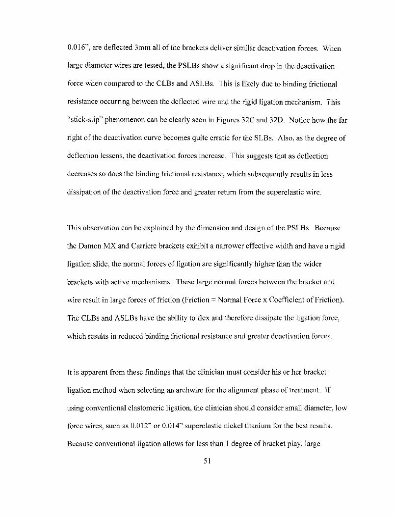
0.016", are deflected 3mm all of the brackets deliver similar deactivation forces. When
large diameter wires are tested, the PSLBs show a significant drop in the deactivation
force when compared to the CLBs and ASLBs. This is likely due to binding frictional
resistance occurring between the deflected wire and the rigid ligation mechanism. This
"stick-slip" phenomenon can be clearly seen in Figures 32C and 32D. Notice how the far
right of the deactivation curve becomes quite erratic for thc SLBs. Also, as the degree of
deflection lessens, the deactivation forces increase. This suggests that as deflection
decreases so does the binding frictional resistance, which subsequently results in less
dissipation of the deactivation force and greater return from the superelastic wire.
This observation can be explained by the dimension and design of the PSLBs. Because
the Damon MX and Carriere brackets exhibit a narrower effective width and have a rigid
ligation slide, the normal forces of ligation are significantly higher than the wider
brackets with active mechanisms. These large normal forces between the bracket and
wire result in large forces of friction (Friction = Normal Force x Coefficient of Friction).
The CLBs and ASLBs have the ability to flex and therefore dissipate the ligation force,
which results in reduced binding frictional resistance and greater deactivation forces.
It is apparent from these findings that the clinician must consider his or her bracket
ligation method when selecting an archwire for the alignment phase of treatment. If
using conventional elastomeric ligation, the clinician should consider small diameter, low
force wires, such as 0.012" or 0.014" superelastic nickel titanium for the best results.
Because conventional ligation allows for less than 1 degree of bracket play, large
5 1

diameter wires are unnecessary for adequate first order control. Also, larger wires
require the elastomeric to provide greater ligation force to maintain the wire's activation,
which could result in a loss of control and reduction in the superelastic range of the wire.
Therefore, even with 50% force decay of the elastomeric, a small diameter Ni'l'i wire
would be more likely to maintain its superelasticity over the full range of activation.
If the clinician prefers the use of SLBs over conventional ligation, archwire selection
should be based on the type of ligation mechanism being used and the width of the first
order couple. As seen in this study, the active In-Ovation R bracket provided adequate
first order control with the 0.014" wire at lmm of deflection, while only the widest
PSLB, SmartClip, was able to gain control when wire diameter was increased to 0.01 8".
In this study, a lmm deflection was equivalent to 11.3 degrees of axial rotation. This
means that even with a 0.0 18" diameter wire, the Damon MX and Carriere brackets could
not provide an adequate couple for correction. This suggests that clinicians using PSLBs
need to consider bracket width and buccolingual archwire dimension when selecting the
appropriate alignment wire.
It appears from our results that ASLBs provide more benefits than PSLBs during the
alignment phase of treatment. The In-Ovation R bracket is narrower than both the
SmartClip and Carriere brackets, but provides a superior reduction in bracket play and
increase in superelastic range. Also, a narrower bracket will provide increased
interbracket distance, resulting in a reduction in activation force of the wire. This means
that the clinician can select a smaller diameter, lower force wire and expect it to work
5 2

over a greater range of activation. In order to gain similar control with PSLBs, the
clinician must use a larger diameter wire, which would lead to an increased deactivation
force and risk of increased sliding frictional resistance.
For instance, a 0.014" superelastic wire coupled with the In-Ovation R bracket will
provide a maximum of 50.24 grams of deactivation force, while providing correction to
within 8 degrees of rotation. A Smartclip bracket would require a 0.01 8" superelastic
wire to provide correction to within 9 degrees of rotation, but this wire would produce a
maximum of 93.39 grams of force. These increased force values with PSLBs might be
remedied by using large diameter thermally activated nickel titanium wires. These wires
could gain first order control earlier in treatment while delivering deactivation forces
equivalent to smaller diameter austenitic wires.
The cantilever model allowed us to isolate forces occurring at the bracket, but did not
take into account interbracket distance, deflection between multiple brackets or sliding
frictional resistance. The three point bend model did allow for multiple brackets and
incorporated sliding frictional resistance. Using these two wire deflection models we
were able to determine that the bracket type and archwire diameter have a significant
effect on the degree of bracket play, deactivation force and superelastic range during first
order tooth movement. This study shows how the ligation mechanism influences the
clinician's ability to achieve full first order correction and to maintain light, continuous
forces over a wide range of activation. Our results suggest that the clinician can improve

the efficiency of force delivery by considering the degree of correction needed and type
of ligation when selecting the appropriate alignment wire.

Conclusions
1. CLBs paired with small diameter superelastic NiTi wires exhibit reduced bracket
play and increased superelastic range when compared with SLBs.
2. ASLBs coupled with small diameter superelastic NiTi wires provide reduced
bracket play and increased superelastic range when compared with PSLBs.
3. PSLBs require larger diameter wires to provide first order control similar to that
of CLBs and ASLBs. If using larger diameter wires, the clinician should consider
thermally active wires to reduce the risk of increased binding frictional resistance.
4. When sliding frictional resistance was limited, PSLBs delivered lower
deactivation forces when compared to CLBs and ASLBs.
5. Due to their narrow width and passive slide, Damon MX and Carriere brackets
exhibited signs of low friction with small diameter wires, but significant binding
frictional resistance with a 3mm deflection of large diameter wires.
6. The Damon MX and Carriere PSLBs showed no significant differences for any
variable measured.


Fi~ure 4: Center of Mass and Center of Resistance
Fig. 1-1 Center 01 resistance. A Center of mass of a free body. B Frontal. C occlusal, and D mesial views of Ihe center of reslstance of a sinale toam.
Figure 5: Center of Resistance in Relation to Alveolar Bone and Root Length
Fig. 1-3 Location ot me center of resistance depends on the alveolar bone height and root length. A Location of the csnter of resistance with alveolar bone loss and B with a shortened root.
Figure 6: Moment of the Force (MF)
flg. 1-7 Moment of a force. A force that does not pass through the center of resistance produces a rotational movement as well as linear movement.

Figure 7: Moment of a Couple with Pure Rotation
Fig. 1-9 Moment of a couple A couple produces pure rolatlon about the center of resistance .- - -
Figure 8: Equivalent Force Systems Diagram
Fig. 1-11 Equivalent force system at a tooth's center of resistance. A Force system applied at the bracket. B Force system at the center of resistance. The force system at the center of resistance describes the expected tooth movement.
Figure 9: Uncontrolled and Controlled Tipping
'v \- ti,
A 4 \j B I s \ 'L
Fig. 1-12 Uncontmlled tipping. A Uncontrolled tipping produced by a single force (no applied moment). B Stress pattern In the periodontal ligament. Notice the rwt apex moves in the opposite dirmtiin from the movement of the crown.
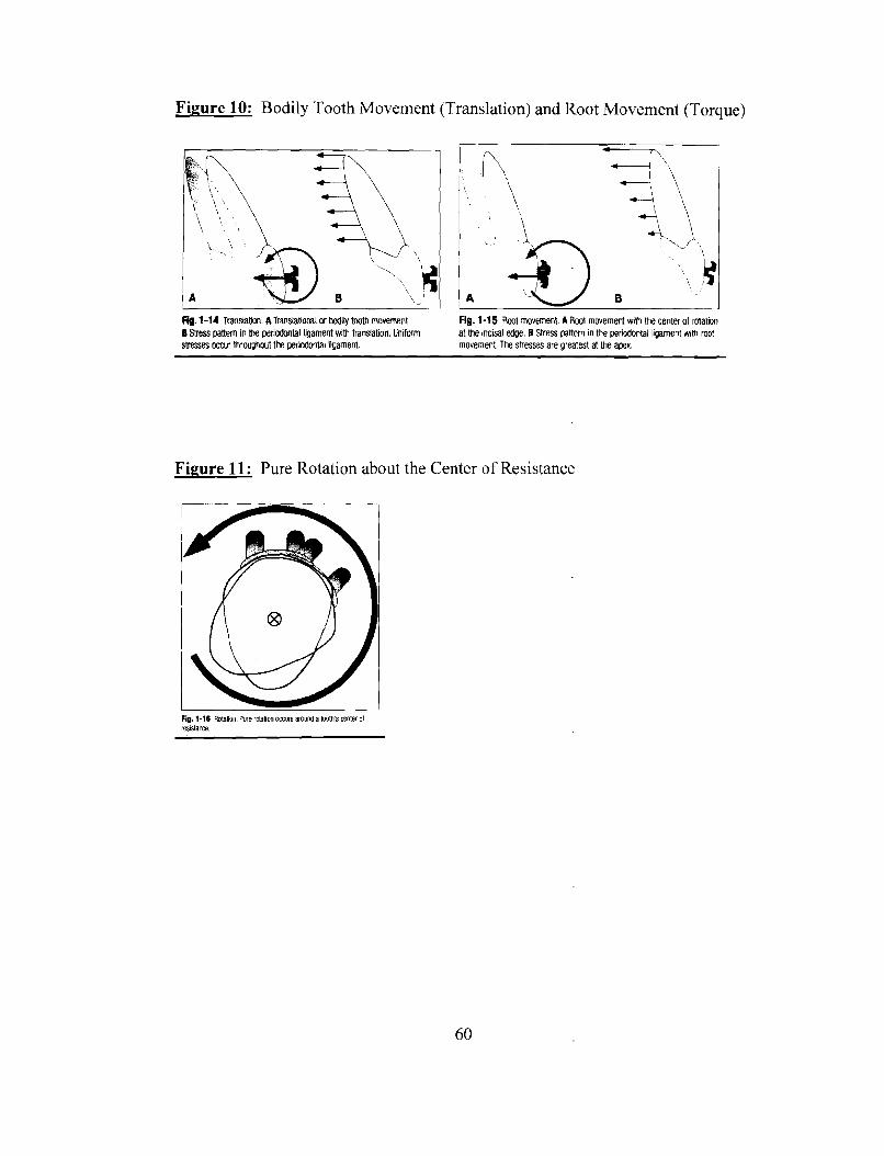
Figure 10: Bodily Tooth Movement (Translation) and Root Movement (Torque)
Y'~ '\
-, \,
Rg. 1-14 Translath. ATranslational or bod$ tooth movement. Fig. 1-15 Root movement. A Root movement with the center of rotation B Stress pattern in the periodontal ligament with translation. Uniform at the incisal edge. B Stress pattern in the periodontal ligament with root stresses occur throughwt the periodontal ligament. movement. The sbesses are greatest at the apex.
Figure 11: Pure Rotation about the Center of Resistance
Fig. 1-16 Rdatm~~. Pure rotation m u r s around a mom's Enter of rm1starm.
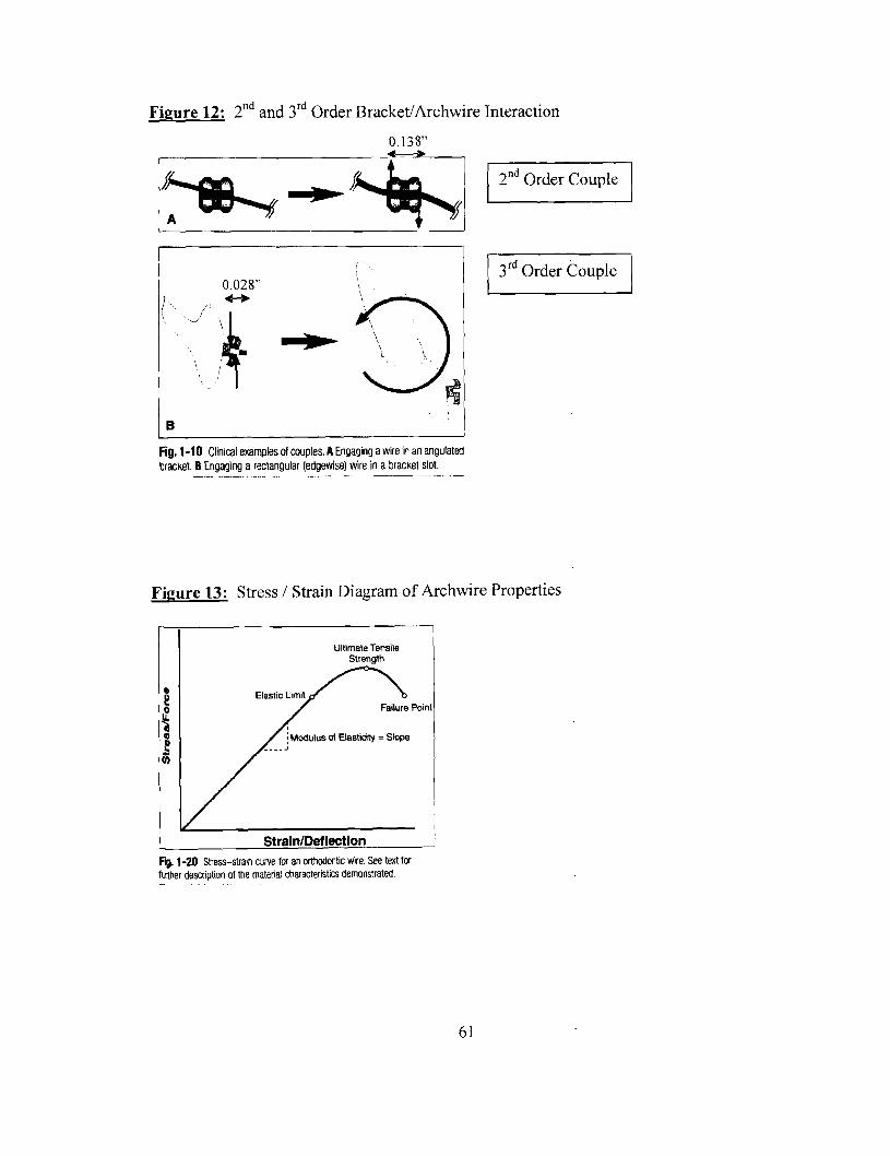
Figure 12: 2nd and 3rd Order BracketIArchwire Interaction
Fig. 1-10 Clinical examples of couples. A Engag~ng a wire In an angulated bracket. B Engaging a rectangular (edgewise) wire in a bracket slot. -- --- - - -- -- - -
Figure 13: Stress 1 Strain Diagram of Archwire Properties
Ultimate Tensile Strength
t 4: 0
2" V)
b. 1-20 Stress-stra~n curve for an orthodont~c wire See text for flather descript~on of the matenal characteristics demonstrated -

Fbure 14: Comparing Angular and Torsional Deflections
ANGULAR DEFLECTION, degree 0 30 60 SO
TORQUE ANGLE. dearee . - W.1.storedensr0~ataRxdbedw-t-Me R g . z 8 0 n d a . R r r d * n i g l l l - ( h . proporbiond Imk for 0.019 by 0.025 Inch uAm d dbya SS, TM, ~WUCUISI ~ t a 0 . 0 1 0 & 0.- ~ ~ h r r l m d m 86, TM, a n d N T . T h e ~ ~ L e q u r r t o t h r M ~ u n & . " d ~ . ~ ~ m r O y * W b ~ - - -
~ ~ ~ e t w e ~ c h u ~ n . T h e ~ p r l n g r r r t e i r q u ~ t o ~ ~ o f ~ ~ ~ m V h ~ m " m o m b ' 8 4 ~ w a r l l o p * each WNe.
Figure 15: MomedDeflection Comparison of Stainless Steel and Nitinol
SPAN = .SO in.
/
DEFLECTION ANGLE DEGREES
Fig. 2 Cornparkon of rectangub nittnol and aclhloss sbel arch Ares in a bending test, simllar to the proposed ADA specllicatbns on ofthadantic wte.

Figure 16: Comparison of Chinese NiTi, Nitinol and Stainless Steel
Fig. 2 Bending moment/- charecteristics of aaintess steel, nitind, end Nit7 wiree. 00th Wing (activation) and un- loeding (deectivation) curvee are shorn. N n win produces lower moments and forcds than nitind wire.
Figure 17: Nickel Titanium Phase Comparison and Temperature Hysteresis

Figure 18: Nickel Titanium Stress Hysteresis
Fig 1. Stress hysteresis, defined as difference between critical stresses in forcedeflectlon curve of Ni-Ti alloy wire, plotted by modified 3-point bending test. Initial martensitlc transformation is at origin of nonlinear elas- ticity (anow).
Fi~ure 19: Comparing Elastomeric Force at Various Time Points
-+ AMR I
i - '--- G A t
' - * -mM I
I -- RMO
1 ' t - UNI !
I,,', 1 - -- - - - ---- - - INlTUL 24 HOURS 7 DAYS 14 DAYS 28 DAYS
TIME
Fig. 7. Percentage of loss of force at initial, 24 hours, 7 days, 14 days, and 28 days
Figure 20: Pictures of Elastomeric Ligatures Before and After Activation
Fie. 4. From left to right, ligatures before testing, after storage (stretched) for 28 days at room temperarure and humidity, and after storage (stretched) for 28 days in simulated oral environment. (Magnif~cation ~ 4 . 1


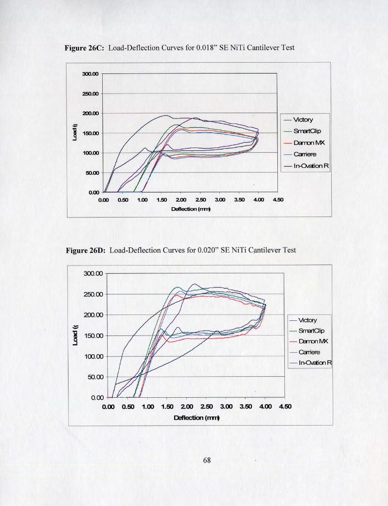

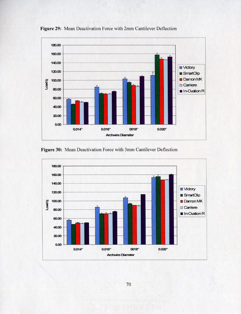
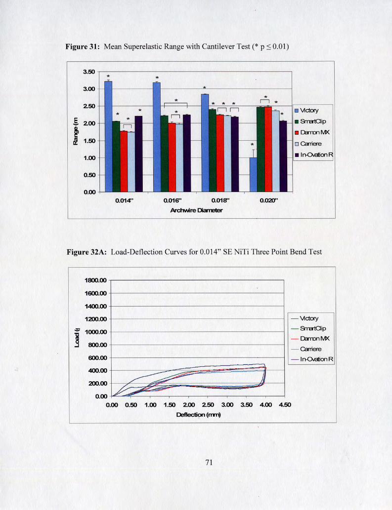


Table I: Description of Brackets Tested.
Slide In-Ovation R ' ~ 1 Interactive I 2.97mm 1 2.97mm 1 Stainless Steel I GAC Intl.
Bracket TY pe
~ r n a r t ~ l i ~ ~ ~
Damon dM
Table 11: Description of Wires Tested.
Ligation Mechanism
Conventional Elastomeric
Passive Clips
Passive Slide
Clip
3.35mm
I Elgiloy Door (
Slot Width
2.98mm
4.15mm
2.67mm
* Distance between the contact points formed during a first-order couple. Varies with the width of
2.84mm
Material
SE NiTi
Effective Width*
3.73mm
3.80mm
2.39mm
TTR
55" F
- -
Diameters Manufacturer
Stainless Steel Class One
Material
Stainless Steel
Stainless Steel NiTi Clips
Stainless Steel
ppp
--- 0.014"
Manufacturer
3M Unitek
3M Unitek
Ormco
0.018" 0.016" 0.020" Bristol, CT

a 8zo.o 6P'Z
a I 10.0 1S'P
a 9 10.0 PP
60'9
3 o 10.0 96'6
3 SOO'O IS' 1 1
E 10.0 6 1'8
3 POO'O 90'6 1
3 610.0 9S.6
3 910'0 9S'lC
o 10.0 6L'P 1
3
a 66'Z 1
0 PZO'O 1S'L
a 900.0 61'6
6zo.o 99'9 l
v 1c0.0 SZ' 1
t/ o 10.0 SS'O
l
o 10.0 80'1 1
.ao~-sod .a-s -- uea~
a
6C'O 1
.aoll-~sod .as
ueaw
*aoq-~sod -a-s
ueaw
- v
000'0 9S'O
POO'O LS'O
,,OZO'O
1 ,,8 10'0
-a-s ueaw

a OP'O
91'0s
3 LP'O
LL'ZZ
a 16.1
ZP'OS
1 E'ZZ SZ'CZ PL'ZZ
8 PO'O £1'0
c ~L'O SS'CS
69 1'0 1 E80'0
SE 1'0
8 PZ'O OP'O
ss.0 P6'SP
L1'0 P9'0 8E'O
8 oz'o SL'O
v ~9' 1
80'LS
PE'O S90'0 91'0
*DOH JSOd
~aa PIS uea~
\d LL 1
96'9s
+=OH $Sod
~aa PIS uea~
8'8s ZP'SS L9'9S 2 l'".'JC

1 'EOU~~!~!U~!S go la~al 10.0 aql le lua~a~!p Allue3!~!u6!s lou a~e ~allal awes ql!~ sueayy . 1
L9'9L 08'SL 96'PL
3 ZP' 1
P6'PL
Z6'OL OS'69 LL' 1L
'
B 61'1 11'69
68'LL 19'ZL LZ'89
a 16.0
P8'96
8 66.0 60'69
86' LL 90'ZL P8'89
3 PO'O SL'O
B SS. I.
66'OL
89'98 66'18 L8'L8
3 ~1.0 LS'O
U'UE
V sz.6 PL'PB
.aOl(-ISOd 1 ~aa PIS
ueaw
a to' 1
9L'S 1
v 1 P"Z
Ot'68
*=OY-ISO~
~aa PIS uea~

l
SS'P 1 1 ZE'P11
i
a ZL'O
SP'P11
V PC' 1
P0'60 1
PL'ES SS'O 6S'O EE'SE LP'EO 1 ZO'SS ZS' 1 1P'O 96'8s
PP'O 8Z'O 6S.96 I
LP'P 1 1 61.88 06'88 16'Z6 80'60 1
10'06 96'88
a 10'1
I E8'PS
3 SO' 1 E8'88
3 LE'Z
PS'S8
12'16 EL'L6
3 6S'O P8'0
tl UO!I~AO-UI
318 99' 1 LZ'06
3 LL'1
66'88
9E'Z6 06'P6
3 91'0 EP'O
aralr~e3
a PE'1 6E'E6
SL'LOL OZ'PO 1
B EZ' 1 6E'S6
a P8' 1 96'9s
v ZS'Z
lO'L01
V S8.Z
1S'EOL
AJOI~A I
.SOH pod AaQ PW 1
uea~
v PZ'Z
8S'PO 1
xw uouea
OH 1s0d AaQ PIS
uea~
OH pod I
AaQ PIS ueaw
d!l3veurg
1

I
€6'1 LO'O s9.s SL 'S ~L.L ~aa PIS SC'SS 1 8S'9P 1 Z9'8P 1 Z8'LS 1 18'0 1 1
a 16.0
ZL'091
v LL'O
S0'8P1
l
a SZ' 1
09'S8 PZ' 18 PO'S8
v SP'Z
L0'8P1
3 91.z
6L' 19 00'6P PZ'SS
altl ~9.s
6L'SS 1
3 z9.s
9P'SP 99'05 89'9P
altl SO'£
P9'SS 1
a PL'~
tl=o~-~sod ~aa PIS
L8'Z6 09'66 11'98
v LS'P
*~OY-FO~ ~aa PIS I
96'8s 86'99 LL.99 wwL ,
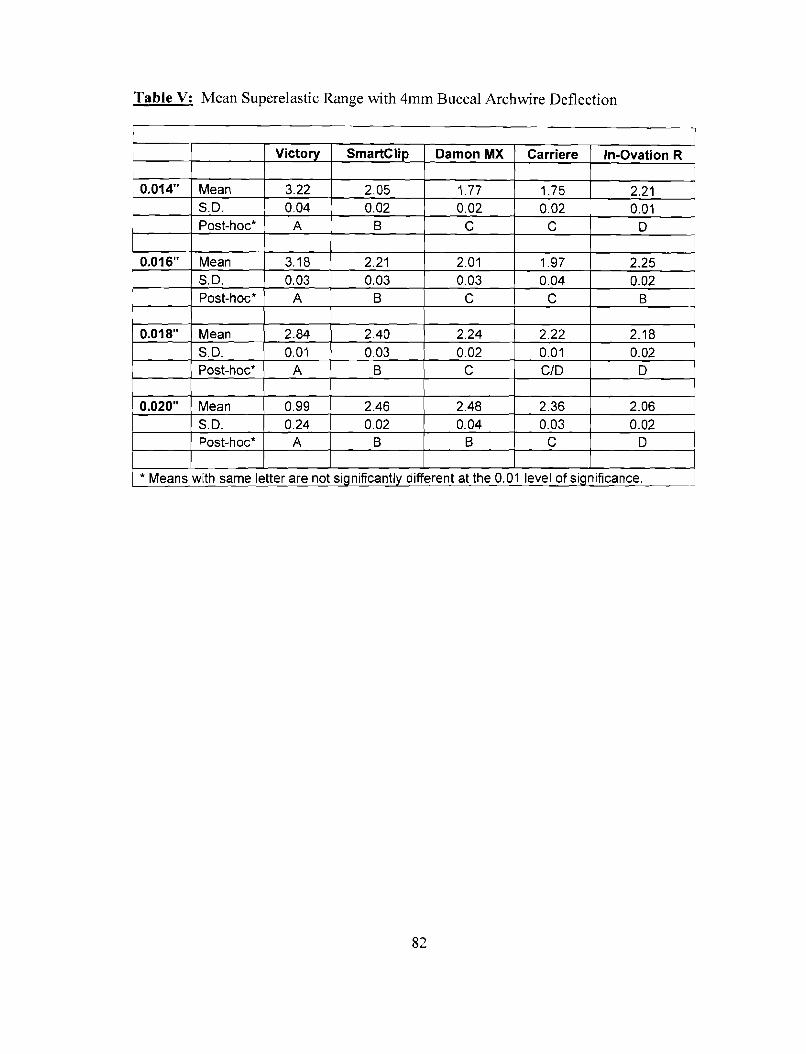
a 10'0
Q 20.0 81'Z
3 10'0
8 10'0 SZ'Z
a13 10.0 22'2
Q
a PO '0
3 PO'O L6' 1
3 zo'o PZ'Z
3
8 10'0
3 EO'O LO'Z
10'0 ZO'O LZ'Z I SL' 1
8 EO'O OP'Z
3
v PZ'O
8 EO'O 1Z'Z
ZO'O LL'1
.~o~-Iso~ 'a's
'd 10.0 P8'Z
8
'd 10'0 81.E
10'0 SO'Z
.304-1SOd
'a's uea W
'd
.,8 C0'0
.3OY-1SOd
'Q'S UeaW
.DO4 -$Sod
PO'O ZZ'E
.,9L0'0 1
'a's L"mll ,,PCO'O 1

-a~ue3!j!u6!sjo lai\al 10.0 a41 je lualau!p /(llue3!~!ub!s IOU ale laljal aues 4j!~ suealry,
P8'9 11 19'6 11 LE'OZL
.~OH-ISO~
Aals OAV
'd EO'P
SL'ZSL
v 9s.o 1
£6'1 11
S1'9P1 LZ'ZS 1 8E'8S 1
9 3 3 8 V
a ZS'E
L0'6E1
8 98'E
PE'991
LP'E SZ'68
v LZ'E
6L'LZL
v 08' t
S8'8 11
PP'LZ 1 EZ'LEL 1L'PZL
9 z1.9
LZ'ZS 1
V 6Z'Z
8L'9S 1
£1'1 L9'8L
11'SEl 9Z'OP 1 P8'1P1
8N 0 1's
68'09 1
10' 1 S9'LL
10'91 1 P8'6 1 1 £6'66 l"UC
V PL'E
PZ'PS 1
SS'E 66'98
JOH-Pod
A~LS J
OAV
1P'Z Z8'1S1
AQlS OAV

'asues14!u6!s 40 laAal 10.0 a4j le juaJag!p Al)ueo!#uS!s jou ale lanai awes 4j!~ sueayy I I I I
1S.P EL'L91
09's LZ I 09'LLZ ( OS'80Z ( 09'8ZZ ( 08'002 ( OL'OOZ I 06'61Z I OL'L 1Z I OP'SZZ I EP'661 I UUZ 1
19'~
L8'L EL'E81
I 60'60Z I OP'OZZ I 00'1 1Z I EP'PZZ I P0'961 I OAV I
80'~
98'6
uo!papaa WINE put? W~IZ 'u1w1 ~t? axed uorp~1)3t?aa Jurod aaqL :a - 111 alqaJ . .
LZ'S 1 L8'09 1
98'LC 1 pp
90'8E 1 LZ' LC 1
98's
EL'S€ 1 I ZE'111 I 96'90 1 LZ'SPL I 90'191 1 OAV I 06'0
PE'L Z1.661
ZL'P 1 60'~ 1 Aals
€0'111
z0.1
E6'Z 1 1 19'0 1 1
9L.8 62'881
LP'P 1 zt"z 1 rials I
-
A~LS OAV
P6'SO 1 ZS'LO 1
PP'ZPL 9E'OS 1
98'191 lO'Z91 UJuL

26'68 1 6S'8L 1 L
OP'OOZ
8 16.11
08'892
9L'OC 1 96'80 1 LL'LPL
09'692 1 OS'9SZ
uop3auaa uu~ pue uurz 'uu~ ~e axed uo!le~!~3eaa p!od aaqL :a - 1~ aIqaL
a SS'L EL.PPZ
v 1
SS'S SS'88 1
9S'9S 1 6S'9S 1 90.~9 1
06'082 OP'ZSZ UUZ
OS'PPZ 06'LCZ
SP'C 1 OZ'SSZ
3 ~v.9
00'2s 1
OS'ZZZ OO'SSZ 08'~~ z
06'ZPZ OZ'PSZ pp
we
V LL'S
£9'601
a 06.z
96'PE 1
OS'LOZ 01'912
SOH-Pod ~als OAW
I
2
v PZ'P
9L.181
1
.30H-ISOd
~als OAW
1

Table VI - D: Three Point Deactivation Force at lmm, 2mm and 3mm Deflection
0.020" SE NiTi Buccal Three Point Bend Deflection
Victory
AVG STDV Post-Hoc* -
AVG STDV Post-Hoc*
- -
I * Means with same letter are not significantly different at the 0.01 level of significance. 1
Damon MX
222.17 10.03
A
AVG STDV Post-HOC*
264.90 9.63
A
Carriere
277.03 12.84
B
327.57 9.07
A
In-Ovation R
338.53 20.86
B
273.03 2.97
B
245.60 16.33
B
270.30 8.12
B
384.23 17.90
B
381.70 11.26
B
278.00 25.76 AIB
304.03 16.62
A

R e f e r e n c e s :
1. Kuhlberg A, Nanda R. Principles of Biomechanics. In: Nanda R, editor. Biomechanics and Esthetic Strategies in Clinical Orthodontics. St. Louis: Elsevier Saunders; 2005. p. 1- 16. 2. van Leeuwen EJ, Maltha JC, Kuijpers-Jagtman AM. Tooth movement with light continuous and discontinuous forces in beagle dogs. Eur J Oral Sci 1999;107:468-474. 3. King GJ, Keeling SD, Wronski TJ. Histomorphometric study of alveolar bone turnover in orthodontic tooth movement. Bone 199 1 ; 12:40 1-409. 4. Proffit WR. Contemporary Orthodontics. St. Louis: Mosby Inc.; 2000. 5. Burstone CJ. Application of Bioengineering to Clinical Orthodontics. In: Graber T, Vanarsdall RL, Vig K, editor. Orthodontics: Current Principles and Techniques. St. Louis: Elsevier Mosby; 2005. 6. Smith RJ, Burstone CJ. Mechanics of tooth movement. Am J Orthod 1984;85:294-307. 7. Burstone CJ, Pryputniewicz RJ. Holographic determination of centers of rotation produced by orthodontic forces. Am J Orthod 1980;77:396-409. 8. Tanne K, Koenig HA, Burstone CJ. Moment to force ratios and the center of rotation. Am J Orthod Dentofacial Orthop 1988;94:426-43 1. 9. Angle E. The latest and best in orthodontic mechanisms. Dent Cosmos 1928;70: 1 143- 1158. 10. Andrews LF. The straight-wire appliance. Explained and compared. J Clin Orthod 1976;10:174-195. 1 1. Kusy RP, Tulloch SF. Analysis of momentlforce ratios in the mechanics of tooth movement. Am J Orthod Dentofacial Orthop 1986;90: 127- 13 1. 12. Kapila S, Sachdeva R. Mechanical properties and clinical applications of orthodontic wires. Am J Orthod Dentofacial Orthop 1989;96: 100- 109. 13. Drake SR, Wayne DM, Powers JM, Asgar K. Mechanical properties of orthodontic wires in tension, bending, and torsion. Am J Orthod 1982;82:206-2 10. 14. Goldberg J, Burstone CJ. An evaluation of beta titanium alloys for use in orthodontic appliances. J Dent Res 1979;58:593-599. 15. Goldberg AS, Morton J, Burstone CJ. The flexure modulus of elasticity of orthodontic wires. J Dent Res 1983;62:856-858. 16. Andreasen GF, Morrow RE. Laboratory and clinical analyses of nitinol wire. Am J Orthod 1978;73:142-151. 17. Burstonc CJ, Qin B, Morton JY. Chinese NiTi wire--a new orthodontic alloy. Am J Orthod 1985;87:445-452. 18. Andreasen GF, Hilleman TB. An evaluation of 55 cobalt substituted Nitinol wire for use in orthodontics. J Am Dent Assoc 1971 $2: 1373-1 375. 19. Santoro M, Nicolay OF, Cangialosi TJ. Pseudoelasticity and thermoelasticity of nickel-titanium alloys: a clinically oriented review. Part I: Temperature transitional ranges. Am J Orthod Dentofacial Orthop 2001; 1 19:587-593. 20. Gil FJ, Planell JA. Effect of copper addition on the superelastic behavior of Ni-Ti shape memory alloys for orthodontic applications. J Biomed Mater Res 1999;48:682-688.

21. Liaw YC, Su YY, Lai YL, Lee SY. Stiffness and frictional resistance of a superelastic nickel-titanium orthodontic wire with low-stress hysteresis. Am J Orthod Dentofacial Orthop 2007; 13 1 :578 e5 12-578. 22. Harradine NW. Self-ligating brackets: where are we now? J Orthod 2003;30:262-273. 23. Forsberg CM, Brattstrom V, Malmberg E, Nord CE. Ligature wires and elastomeric rings: two methods of ligation, and their association with microbial colonization of Streptococcus mutans and lactobacilli. Eur J Orthod 199 1 ; 13 :4 1 6-420. 24. Taloumis LJ, Smith TM, Hondrurn SO, Lorton L. Force decay and deformation of orthodontic elastomeric ligatures. Am J Orthod Dentofacial Orthop 1997; 1 1 1 : 1 - 1 1. 25. Brantley WA, Salander S, Myers CL, Winders RV. Effects of prestretching on force degradation characteristics of plastic modules. Angle Orthod 1979;49:37-43. 26. Eberting JJ, Straja SR, Tuncay OC. Treatment time, outcome, and patient satisfaction comparisons of Damon and conventional brackets. Clin Orthod Res 2001 ;4:228-234. 27. Harradine NW. Self-ligating brackets and treatment efficiency. Clin Orthod Res 200 1 ;4:220-227. 28. Voudouris JC. Interactive edgewise mechanisms: form and function comparison with conventional edgewise brackets. Am J Orthod Dentofacial Orthop 1997; 1 1 1 : 1 19- 140. 29. Bednar JR, Gruendeman GW, Sandrik JL. A comparative study of frictional forces between orthodontic brackets and arch wires. Am J Orthod Dentofacial Orthop 1991;100:5 13-522. 30. Berger JL. The influence of the SPEED bracket's self-ligating design on force levels in tooth movement: a comparative in vitro study. Am J Orthod Dentofacial Orthop 1990;97:219-228. 3 1. Pizzoni L, Ravnholt G, Melsen B. Frictional forces related to self-ligating brackets. Eur J Orthod 1998;20:283-29 1. 32. Rinchuse DJ, Miles PG. Self-ligating brackets: present and future. Am J Orthod Dentofacial Orthop 2007; 132:2 16-222. 33. Bednar JR, Gruendeman GW. The influence of bracket design on moment production during axial rotation. Am J Orthod Dentofacial Orthop 1993; 104:254-26 1. 34. Nanda R, Ghosh, J. Biomechanics in Clinical Orthodontics. Farmington, CT: Saunders; 1997. 35. Angolkar PV, Kapila S, Duncanson MG, Jr., Nanda RS. Evaluation of friction between ceramic brackets and orthodontic wires of four alloys. Am J Orthod Dentofacial Orthop 1990;98:499-506. 36. Kusy RP, Whitley JQ. Effects of surface roughness on the coefficients of friction in model orthodontic systems. J Biomech 1990;23:913-925. 37. Kusy RP, Whitley JQ. Frictional resistances of metal-lined ceramic brackets versus conventional stainless steel brackets and development of 3-D friction maps. Angle Orthod 2001 ;7 1 :364-374. 38. Kusy RP, Whitley JQ, Prewitt MJ. Comparison of the frictional coefficients for selected archwire-bracket slot combinations in the dry and wet states. Angle Orthod 1991 ;6 1 :293-302. 39. Downing A, McCabe J, Gordon P. A study of frictional forces between orthodontic brackets and archwires. Br J Orthod 1994;21:349-357.

40. Drescher D, Bourauel C, Schumacher HA. Frictional forces between bracket and arch wire. Am J Orthod Dentofacial Orthop 1989;96:397-404. 41. Kapila S, Angolkar PV, Duncanson MG, Jr., Nanda RS. Evaluation of friction between edgewise stainless steel brackets and orthodontic wires of four alloys. Am J Orthod Dentofacial Orthop 1 990;98: 1 17- 126. 42. Tidy DC. Frictional forces in fixed appliances. Am J Orthod Dentofacial Orthop 1989;96:249-254. 43. Kusy RP, Whitley JQ. Friction between different wire-bracket configurations and materials. Semin Orthod 1997;3: 166- 177. 44. Frank CA, Nikolai RJ. A comparative study of frictional resistances between orthodontic bracket and arch wire. Am J Orthod 1980;78:593-609. 45. Thorstenson GA, Kusy RP. Effect of archwire size and material on the resistance to sliding of self-ligating brackets with second-order angulation in the dry state. Am J Orthod Dentofacial Orthop 2002; 122:295-3 05. 46. Kusy RP, Whitley JQ. Influence of archwire and bracket dimensions on sliding mechanics: derivations and determinations of the critical contact angles for binding. Eur J Orthod 1999;21: 199-208. 47. Andreasen GF, Quevedo FR. Evaluation of friction forces in the 0.022 x 0.028 edgewise bracket in vitro. J Biomech 1970;3: 15 1-1 60. 48. Vaughan JL, Duncanson MG, Jr., Nanda RS, Currier GF. Relative kinetic frictional forces between sintered stainless steel brackets and orthodontic wires. Am J Orthod Dentofacial Orthop 1995; 107:20-27. 49. Ogata RH, Nanda RS, Duncanson MG, Jr., Sinha PK, Currier GF. Frictional -
resistances in stainless steel bracket-wire combinations with effects of vertical deflections. Am J Orthod Dentofacial Orthop 1996; 109535-542. 50. Ash JL, Nikolai RJ. Relaxation of orthodontic elastomeric chains and modules in vitro and in vivo. J Dent Res 1978;57:685-690. 5 1 . Shivapuja PK, Berger J. A comparative study of conventional ligation and self- ligation bracket systems. Am J Orthod Dentofacial Orthop 1994; 106:472-480. 52. Iwasaki LR, Beatty MW, Randall CJ, Nickel JC. Clinical ligation forces and intraoral friction during sliding on a stainless steel archwire. Am J Orthod Dentofacial Orthop 2003;123:408-415. 53. Henao SP, Kusy RP. Evaluation of the frictional resistance of conventional and self- ligating bracket designs using standardized archwires and dental typodonts. Angle Orthod 2004;74:202-2 11. 54. Henao SP, Kusy RP. Frictional evaluations of dental typodont models using four self- ligating designs and a conventional design. Angle Orthod 2005;75:75-85. 55. Miles PG, Weyant RJ, Rustveld L. A clinical trial of Damon 2 vs conventional twin brackets during initial alignment. Angle Orthod 2006;76:480-485. 56. Miles PG. Smartclip versus conventional twin brackets for initial alignment: is there a difference? Aust Orthod J 2005;21: 123- 127. 57. Miles PG. Self-ligating vs conventional twin brackets during en-masse space closure with sliding mechanics. Am J Orthod Dentofacial Orthop 2007; 132:223-225. 58. Braun S, Bluestein M, Moore BK, Benson G. Friction in perspective. Am J Orthod Dentofacial Orthop 1999; 1 15 :6 19-627.

59. Redlich M, Mayer Y, Harari D, Lewinstein I. In vitro study of frictional forces during sliding mechanics of "reduced-friction" brackets. Am J Orthod Dentofacial Orthop 2003; 124:69-73. 60. Tecco S, Festa F? Caputi S, Traini T, Di Iorio D, DIAttilio M. Friction of conventional and self-ligating brackets using a 10 bracket model. Angle Orthod 2005;75:1041-1045. 61. Thorstenson GA, Kusy RP. Effects of ligation type and method on the resistance to sliding of novel orthodontic brackets with second-order angulation in the dry and wet states. Angle Orthod 2003;73:418-430. 62. Quinn RS, Yoshikawa DK. A reassessment of force magnitude in orthodontics. Am J Orthod 1985;88:252-260. 63. Southard TE, Marshall SD, Grosland NM. Friction does not increase anchorage loading. Am J Orthod Dentofacial Orthop 2007; 13 1 :412-4 14. 64. Kim TK, Kim KD, Baek SH. Comparison of frictional forces during the initial leveling stage in various combinations of self-ligating brackets and archwires with a custom-designed typodont system. Am J Orthod Dentofacial Orthop 2008; 133: 187 e l 15- 124. 65. Pandis N, Eliades T, Partowi S, Bourauel C. Forces exerted by conventional and self- ligating brackets during simulated first- and second-order corrections. Am J Orthod Dentofacial Orthop 2008; 133:738-742. 66. Creekmore TD. The importance of interbracket width in orthodontic tooth movement. J Clin Orthod 1976:10:530-534. 67. Hemingway R, Williams RL, Hunt JA, Rudge SJ. The influence of bracket type on the force delivery of Ni-Ti archwires. Eur J Orthod 2001 ;23:233-241.


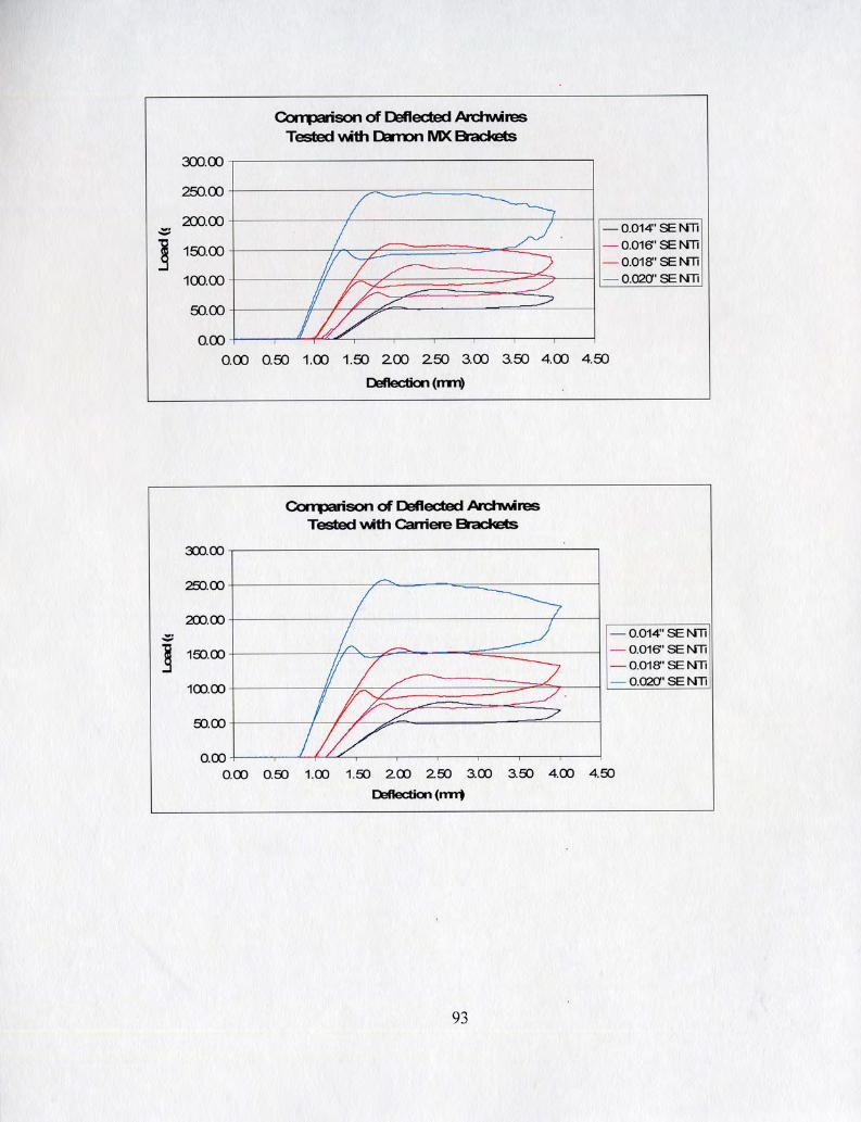


LS-O 6P0'0
LPO'O PSO'O LPO'O
69'1 ~9.1
80'LS
99.v 1 806' 1
Z ~8.z
9 L'L9
PS'69 S6'L9 LO'P9
016'1 1 OSS'L
1 s ZS'6S
1Z.Z z
L8'SS
81's ZL'S 19'L9
1
c 1.8 SLL'O
86'LS 1L'SS 6
L8'P9 S6'S9
6ZL'O - OLL'O SOL'O
aaJod 6s uo!Jaal4aa
SL'1 LL'L
96'9s
00'1 ~8.0
L8'6P
SS'O ~9.0 08'L9
PL'8S P
60'LS
S6'8P 9L'LP
16P.89 69'L9 ZZ'L9
OO'P
LL'Z SP'Z
90'1s
P8'0 ~L'O
SS'SS
SS'O 9v.0 PZ'OS
JoJJ3 % as
OAV
P9'09 LL'6S 19'LS
SZ'LS 16'8P
(uw) uo!g~ayaa
PL'OS P8'6P PL'OS
00'C
9 ~8.0
6S.61
9P'O OP'O 9Z'OS
8'8s 2' L9'9S
ZZ'OZ LZ'L1
8'69 SO 8P'OS
00'1
LZ'PS PZ'O OP'O
LL'O 99.0 L 1'89
9L'SG 86'8P SP'OS
€80'0 SS1'0
SP'LP 19'89 LP'8P
OS'L
~OP!A 26'6 80.0 PP'O
61'1 LP'O
LL'ZZ
JoJJ3 % as
OAV
01'0 L1'0
1S'ZZ ------ '€2 PL'ZZ
00.1
arayre3
89.81 ~1.0 SP'O-
19'0- PS'O- OP'O-
09.0
JOJJ3 % as
OAV
a-uo!geAou(
1

' 6P0'0 1 lZ'S01 1 S9'S8 1 PL'P8 I PZ'E8 I OP'E8 1 LZ'PL 1 OAV I 1
9S0'0 8P0'0 ZPO'O
- - -
091'1 1 Zl'E01 1 68'1L 1 ZP'69 1 99'ES 1 PE'O 1 8S'O 1
66'Z 1 ES1'1
Z6'LOL 88'801 ZE'ZO1
9E'l LE'Z
EP'OOL
6C'O 1 L 16'0
89'98 6E'Z8 L8'L8
6P6'0 6 16'0 Z88'0
68'1 EE'Z
Z6'OL
OL'1 L8'Z SP'L6
90.c c 091'1
9E'P8 69'18 91'88
LP'86 11'66 ZZ'P6
Z91'1 SS1'1 €91'1
€8'0 66'0
60'69
8E.1 OL'1
9L.O.l -----
ZP'O LL'O
P6L6
98'P8 SL'18 Zl'E8
8E'L.L 90'ZL P8'89
OP'L6 L9'L6 PL'86
S9'E 6
SS'OS
LZ'1 1
6E'OL
P6'0 ~1.1
EL'OL
EP'Z8 LS'08 61'L8
P8'OL L9'1L L9'89
Z6'OL OS'69 LL'LL
8Z.61 L1'0 LS'O
PP'1 18'1
OP'ZL
0 EL
Z1'69
SS'EL 9L'LL OS'1.L
ZL'EL PL'EL SE'OL
EZ'OL 6L'L9 EE'69
~OP!A
SP'LL E1'0 EP'O
69'E 10'1
69'0 6v.0
OS'8P
JoJJ3 Oh as
OAV
SZ'S1 16'91 11'SL
OE'8P 90'6P P1'8P
6E'PZ ZL'O
%a P1'0- PE'O- PE'O-
SL'S1 PO'O S1'0
01'0 L1'0 pppp
L1'0
10.113 %
as OAV -
09'LL LO'O ZZ'O
11'0 OE'O OZ'O
JoJJ3 %
as 9AV
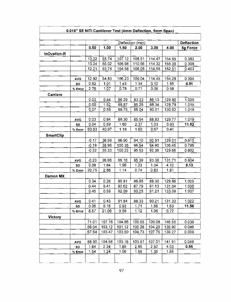
SS'O 8P0'0
, 6'20'0 SS'9P1 80'601 SO 98'POl 91'LOl 10'1L
P9'1 '2O'P
16'1P1
9s' C L ZZO'L
L'20'1 300'1
1P'O L9'0 09'1 81'1 L6'OP '28'09 1 J0JJ3 %
---- --- ZS'CC '26'0 €0'1 '2 08'1 63'0 PO'O as
18'1
9 ZZ
LO'L01
ZL'O 9
'2'2'1'21
80'CEL PO'1'21
'28'0
S10'1 SZO'L
6 8
LS"201
90'1 99'1 lZ'06
12'16 '21'16
CS-P P66'0
PL'O
8L.811 06'6Z1
EOP'O 86'2'0 28'2'0
90'1 68'1
91"201
Z1'L 1L.1
'2'2'88
SZ'06 6L'L8
8S'O s
8Z'PSL
a=Jod6s uo!l=aljaa
P1'1
P'2'88 '21'88
1S'ZSL 8E'SSL 36'9s 1
PZ'1 PZ'Z
8S'FOl
82'0 '26'0 P8'16
60'Z6 Z9.16
90'0 1.0
SP'P1 1
OO'P
88'Z
~ ~
8 6'2'68
SS'P11 Z6'Pl 1 LP.Pl1
1 P8'1 06'89
90'1Z 91'0 EP'O
6S'O 1P'O
1L'O PE'L
P0'601
(uu) uo113ayaa OO'C
J0JJ3 %
as 9Av
SL'OZ
L8'88 62'98
30'801 9S'OL 1 12'801
LS'8 90'0 1P'O
SP'O PP'O
8L'O cv.1
€1'901
00'1
J0JJ3
as 9Av
I
'OJJ3 %
1 PP'O
8S'POL 86'901 ZL'L01
P
XW uou"?a 1
LO'L 10.1
E8'PS
00'0 €0'0
PL'ES ZO'SS PL'SS
OS'C
alaye3
9L'Z z9.0 16.21
LZ'Z1 PZ'EL Z6'61
OS'O 00'C
J0JJ3 %
as 9Av
N-uo!jeAOul

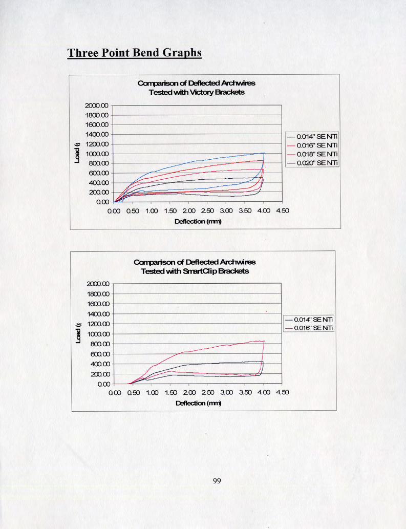


0.014" SE NiTi 3pt Bend Test (4mm Deflection, 10mm Span)
AVG SD
1 I I I I I I I I
/ AVG 1 15.71 1 78.67 ( 135.77 1 166.34 1 152.27 1 1 0.417 1
I 1 AVG I 16.82 77.65 127.64 I 156.78 I 1 0 . 4 1 6 1 127.79
38.93 0.984
Carriere - 77.98 79.98 ---
135.37 131.22 15.86
89.25 3.472
78.06 --------
Victory
169.78 167.06 162.17
)
138.04 5.226
--- 158.38
146.15
SD
AVG SD
0.891 143
135.7 130.16
0.291 3.33
I
136.29 6.440
152.15 4.026
1.017 151.26 154.46 -------- 149.74
118.85 1.801
151.82 ----- 2.409
2.388 163.11 168.57 158.23
163.30 5.173
2.288 152.76 157.85 152.12
154.24 3.140
3.274 99.93 119.84 116.01
0.052 111.93
-7G-
4.76 0.014 0.070
7zF-

I I I I I I I I I
1 SLS'O 1 1 Cl'C81 1 OP'OZZ 1 L0'91Z )Z€'111 1 61'9s 1 9AV I I

SSO'O I I OS'ZZZ I OS'LOZ 1 6Z.161 1 Z6'6L1 1 ZZ'6S 1 1
CIS 9AV
89'0 ZPO'O
( 961'81 ( LOL'S ( 616.S ( SSZ'P ~01'P~Z(69'60Z]01'961(9L'181
1 I
L9'E 1Z6'0
PZ1'9 61'691
0 1'9 tZ 06'SOZ --------
660'0 L60'0
I
LZ6'0 8 16'0
00'SSZ 08'PZZ
LZS'P L0'6S 1
PS1'0 P9 1 '0 S9 1'0
OL'ZOZ OE'P6 1
-------- L 16'0 90'P91 01'69Z 00'06Z Zg'L61 Z9'PS
9S'9S1 6S'9S1
aa~od 69
uo!39al4aCl
8ZP'61 OZ'GSZ
Z6'68 1 6S'8L1 OP'OOZ
09'98 1 SL'8L 1
OG'ZPZ OZ'PSZ
OO'E
PZ'OL 1 0 1'091
SPZ'6 6Z.681
09'692 OS'9SZ -------- 06'082
OL'ZLZ OO'L8Z
(UU) uo!payaa 00'1
SOE'Z 96'PCt
OZ'8SZ 06'ZSZ 08'6SZ
OS'661 LL'661
OS'C
06P'l 16'SS
6Z'PS ZO'LS
6 1 'P6 1 60'681 86'88 1
CIS 9AV
8 1'00 1 P8'96 PS'L6
OO'C OS'O
a-uo!geAOul