FIRST Electrical Design Michael Dessingue College Mentor - Hudson Valley Community College...
51
FIRST Electrical FIRST Electrical Design Design Michael Dessingue Michael Dessingue College Mentor - Hudson Valley Community College College Mentor - Hudson Valley Community College [email protected] [email protected] Team 250 Team 250 Steve Shade Steve Shade Controls and Simulation Engineer – Rolls-Royce Controls and Simulation Engineer – Rolls-Royce [email protected] [email protected] Teams 1111 & 7 Teams 1111 & 7 Al Skierkiewicz Al Skierkiewicz Broadcast Engineer - WTTW-TV Broadcast Engineer - WTTW-TV [email protected] [email protected] Team 111 Team 111
-
date post
20-Dec-2015 -
Category
Documents
-
view
214 -
download
0
Transcript of FIRST Electrical Design Michael Dessingue College Mentor - Hudson Valley Community College...

FIRST Electrical FIRST Electrical DesignDesignMichael Dessingue Michael Dessingue
College Mentor - Hudson Valley College Mentor - Hudson Valley Community CollegeCommunity College
[email protected]@nycap.rr.comTeam 250Team 250
Steve ShadeSteve ShadeControls and Simulation Engineer – Rolls-Controls and Simulation Engineer – Rolls-
[email protected]@rolls-royce.com
Teams 1111 & 7Teams 1111 & 7
Al SkierkiewiczAl SkierkiewiczBroadcast Engineer - WTTW-TVBroadcast Engineer - WTTW-TV
[email protected]@networkchicago.comTeam 111Team 111
OverviewOverview
Electrical kit and IFI HardwareElectrical kit and IFI Hardware Layout and PlanningLayout and Planning Resistance and Ohm’s LawResistance and Ohm’s Law Electrical ToolsElectrical Tools Myth-BustingMyth-Busting QuestionsQuestions

IFI HardwareIFI Hardware
Planning Your Electrical Planning Your Electrical SystemSystem
Plan, create drawings just like Plan, create drawings just like mechanical systemsmechanical systems
Create a test bed earlyCreate a test bed early Use test bed to test all systems before Use test bed to test all systems before
integratingintegrating Communicate effectively with the Communicate effectively with the
mechanical sub-teams early and oftenmechanical sub-teams early and often Document everythingDocument everything

Documentation ExampleDocumentation Example
Team 1111 Team 1111 Robot Controller Robot Controller OutputsOutputs
OutputsOutputs DescriptionDescription ColorColor CBCBB/B/
CC
PWM1PWM1 Drive LeftDrive Left RedRed 40-240-2 CC
PWM2PWM2 Drive LeftDrive Left BlueBlue 40-440-4 CC
PWM3PWM3 Drive RightDrive Right GreenGreen 40-640-6 CC
PWM4PWM4 Drive RightDrive Right YellowYellow 40-540-5 CC
PWM5PWM5 LiftLiftOrangOrang
ee 40-140-1 BB
PWM6PWM6 LiftLift BrownBrown 40-340-3 BB
PWM7PWM7 WristWrist WhiteWhite 1-201-20 BB

General Layout TipsGeneral Layout Tips Label and/or Color Code Label and/or Color Code
EverythingEverything Secure wire so a hit from Secure wire so a hit from
another robot doesn't stretch another robot doesn't stretch the wiring to a breaking point the wiring to a breaking point or pull a terminal out of a or pull a terminal out of a breaker, victor or spikebreaker, victor or spike
When in doubt, insulateWhen in doubt, insulate Secure the battery so it Secure the battery so it
doesn't fall outdoesn't fall out Leave some slack in wire to Leave some slack in wire to
allow for swapping of partsallow for swapping of parts Be careful when running Be careful when running
wiring through frame wiring through frame members so that mech heads members so that mech heads don't drill into it at some don't drill into it at some point down the roadpoint down the road

FIRST Electrical ProblemFIRST Electrical Problem
How much voltage is lost in a How much voltage is lost in a typical FIRST circuit?typical FIRST circuit?
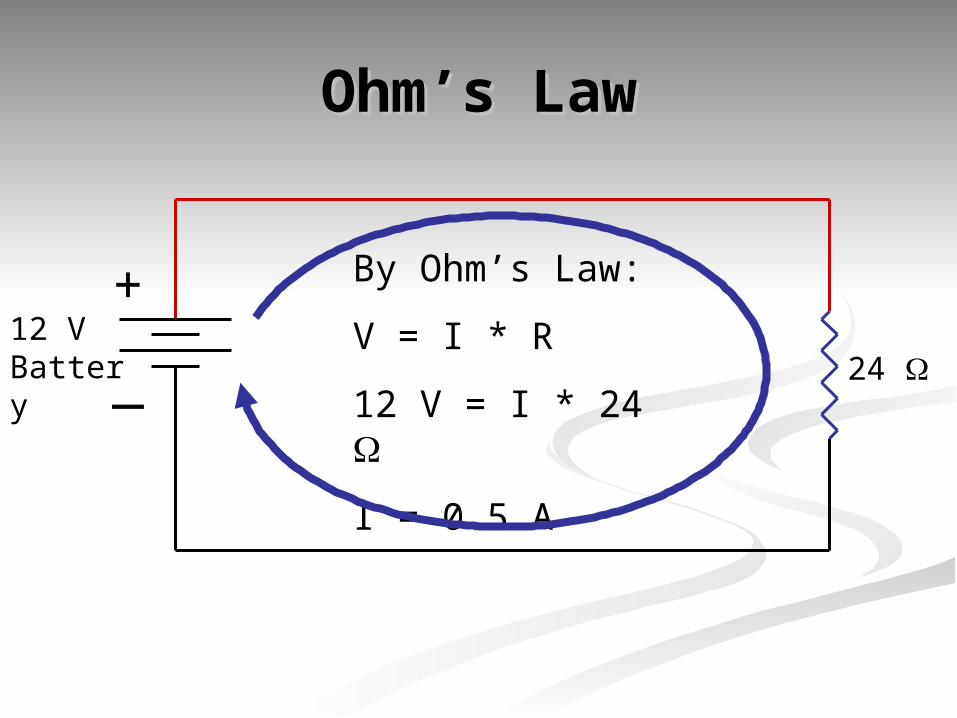
Ohm’s LawOhm’s Law
+
_12 VBattery 24
By Ohm’s Law:
V = I * R
12 V = I * 24
I = 0.5 A

Typical FIRST CircuitTypical FIRST Circuit
Victor 884Speed
Controller
+
_
40 A Circuit Breaker Vout
Measured
Assuming the Victor 884 Speed Controller is given an input signal of 254 from the Robot Controller, how much voltage is output to the device?
12 VBattery
Ideal ValueIdeal Value 12 V12 V
Actual ValueActual Value 0V to ~11.63 0V to ~11.63 VV
120 A Circuit Breaker

Typical FIRST CircuitTypical FIRST Circuit
Victor 884Speed
Controller
+
_
40 A Circuit Breaker Vout
Measured
Circuit consists of 8’ of #6, 4’ of #10, and 2’ of #10.
14 Connections in the circuit
12 VBattery
Ideal ValueIdeal Value 12 V12 V
Actual ValueActual Value 0V to ~11.63 0V to ~11.63 VV
120 A Circuit Breaker

More Wire Adds More More Wire Adds More ResistanceResistance
““Standard Wire Foot” - A 10 gauge Standard Wire Foot” - A 10 gauge wire will drop about 0.1 volt per foot wire will drop about 0.1 volt per foot at the stall current of any of the at the stall current of any of the drive motors. drive motors.
There is resistance in every wire There is resistance in every wire .001 ohm/ft #10 wire.001 ohm/ft #10 wire .0004 ohm/ft #6 wire.0004 ohm/ft #6 wire

Typical FIRST CircuitTypical FIRST CircuitResistances:Resistances: 8’ #6 = 8’ #6 = 0.0032 0.0032
6’ #10 = 6’ #10 = 0.0060 0.0060 Rtotal = Rtotal = 0.00920.0092
Steady State Current:Steady State Current: 40 A40 AVoltage Drop Voltage Drop = I*R = 40 A * 0.0092 = I*R = 40 A * 0.0092
= 0.368 V= 0.368 V
Max Voltage at DeviceMax Voltage at Device = 12V - = 12V - 0.368V0.368V
= 11.632 V= 11.632 V

Typical FIRST CircuitTypical FIRST CircuitResistances:Resistances: 8’ #6 = 8’ #6 = 0.0032 0.0032
6’ #10 = 6’ #10 = 0.0060 0.0060 Rtotal = Rtotal = 0.00920.0092
CIM Motor Stall Current:CIM Motor Stall Current: 114 A114 AVoltage Drop Voltage Drop = I*R = 114 A * 0.0092 = I*R = 114 A * 0.0092
= 1.05 V= 1.05 VMax Voltage at DeviceMax Voltage at Device = 12V - 1.05V= 12V - 1.05V
= 10.95 V= 10.95 V
At Stall Current of CIM, Max Voltage at At Stall Current of CIM, Max Voltage at the CIM motor for the same current the CIM motor for the same current path is path is 10.95V!10.95V!

Reducing ResistanceReducing Resistance
Check every crimp to make sure the Check every crimp to make sure the wires do not move or turn when wires do not move or turn when pulledpulled
Use the correct tool for the jobUse the correct tool for the job Solder all critical jointsSolder all critical joints Shorten the length of your wires Shorten the length of your wires
(also helps in keeping things neat (also helps in keeping things neat and traceable)and traceable)

Crimp ConnectionsCrimp Connections
Buy a good crimper for about $20Buy a good crimper for about $20 Home Depot, Lowes Electrical SectionsHome Depot, Lowes Electrical Sections Many Auto Parts Stores also stock Many Auto Parts Stores also stock
crimpers crimpers Look for crimper with good handles and Look for crimper with good handles and
can used with wire gauges 10 to 24can used with wire gauges 10 to 24

SolderingSoldering
Good Practice to solder all connections Good Practice to solder all connections where high currents existwhere high currents exist
Use Appropriate Size iron for the jobUse Appropriate Size iron for the job Use a Rosin Core Solder for all electronicsUse a Rosin Core Solder for all electronics
Wire SizeWire Size Min Power Min Power (W)(W)
Max Power Max Power (W)(W)
66 6060 100+100+
1010 4040 8080
1616 3030 6060
2424 2020 3030

Other Required ToolsOther Required Tools
Multimeter (DMM)Multimeter (DMM) VoltageVoltage ResistanceResistance Continuity Continuity
Wire StrippersWire Strippers Re-strip any wires where copper Re-strip any wires where copper
strands are loststrands are lost

Myth-BustingMyth-Busting

The RC, OI, Victors and Spikes The RC, OI, Victors and Spikes need external components need external components
to run (i.e. capacitors, to run (i.e. capacitors, voltage regulators, etc.)voltage regulators, etc.)
IFI has done a good job of designing the IFI has done a good job of designing the power and internal circuitry of all the kit power and internal circuitry of all the kit electronic components. There is no electronic components. There is no additional circuitry required for reliable additional circuitry required for reliable operation. The fan that is mounted on operation. The fan that is mounted on the speed controller is required though the speed controller is required though and most teams will wire this fan to the and most teams will wire this fan to the controller power input. The fan then controller power input. The fan then becomes an indication of good input becomes an indication of good input power to the controller.power to the controller.

The controllers can’t go The controllers can’t go from forward to from forward to reverse quickly.reverse quickly.
The speed controllers do exactly what The speed controllers do exactly what you tell them to do. Your robot cannot you tell them to do. Your robot cannot make the sudden changes you are make the sudden changes you are demanding for other reasons related to demanding for other reasons related to mechanical design and physics. You mechanical design and physics. You cannot hope that the control system will cannot hope that the control system will overcome all other losses. It does not overcome all other losses. It does not have the power resources to overcome have the power resources to overcome the momentum of a charging 130 lb. the momentum of a charging 130 lb. robot and change it’s direction.robot and change it’s direction.
The controllers and The controllers and motors are not matched, motors are not matched,
the switching is all the switching is all wrong.wrong. This may seem to be the case, but This may seem to be the case, but
the components work very well the components work very well together. All teams use the same together. All teams use the same motors and drive components so motors and drive components so there is no disadvantage to any team there is no disadvantage to any team using the supplied parts.using the supplied parts.

The OI says my battery The OI says my battery voltage is 10.5 but my voltage is 10.5 but my
voltmeter reads 12 at the voltmeter reads 12 at the battery. It must be battery. It must be
broken.broken. Your RC voltage monitor accurately Your RC voltage monitor accurately reads the voltage that is present at it’s reads the voltage that is present at it’s input. If your RC reads 10.5 volts, there input. If your RC reads 10.5 volts, there is considerable loss in the wiring and is considerable loss in the wiring and connections. Check that you have connections. Check that you have connected the RC to the #1 or #2 connected the RC to the #1 or #2 positions on the breaker panel and positions on the breaker panel and check that your connectors are well check that your connectors are well crimped and are tight and fully engaged crimped and are tight and fully engaged on the push on connections.on the push on connections.


The battery is too small.The battery is too small.
The battery is actually very powerful. The battery is actually very powerful. Most teams have no problem driving a Most teams have no problem driving a 130 pound robot for more than two 130 pound robot for more than two matches with the kit battery. If your matches with the kit battery. If your robot drains a charged battery by the robot drains a charged battery by the end of a match, the mechanical design end of a match, the mechanical design is inefficient or you are using some is inefficient or you are using some form of tank drive. (treads or four or form of tank drive. (treads or four or more non-steering drive wheels)more non-steering drive wheels)

TYPE ES18-12
CAPACITY
5HR 3.06A 15.3 AH
1HR 10.80A 10.8 AH
1C 18.0A 9.0 AH
INTERNAL RESISTANCE APPROX. 15m
MAX. DISCHARGE CURRENT 230 A (5 SEC.)
MAX. CHARGE CURRENT 5.34
The main battery cannot The main battery cannot be used lying down.be used lying down.
The main battery can be used in The main battery can be used in any orientation, including upside any orientation, including upside down. It can be charged in any down. It can be charged in any direction except upside down. direction except upside down. Battery terminals must be Battery terminals must be protected at all times and the protected at all times and the battery must be secured in the battery must be secured in the robot. You can’t play when your robot. You can’t play when your battery is lying on the field.battery is lying on the field.

A sparking motor is A sparking motor is defectivedefective
Sparks are normal in DC brush Sparks are normal in DC brush type motors. The magnetic fields in type motors. The magnetic fields in a motor generate high voltages that a motor generate high voltages that spark across gaps in the brush spark across gaps in the brush assembly. Motors that are working assembly. Motors that are working hard or have worn brushes produce hard or have worn brushes produce more sparking.more sparking.

I can only get 11 volts at I can only get 11 volts at my motor running. The my motor running. The
breaker panel is breaker panel is defective.defective. This actually is an effect of the some of the This actually is an effect of the some of the
principles discussed earlier. High currents in the principles discussed earlier. High currents in the wires we use result in some voltage drop. wires we use result in some voltage drop. Measuring at the motor, is in effect, compensating Measuring at the motor, is in effect, compensating for this loss. Remember the wire foot, every foot for this loss. Remember the wire foot, every foot of #10 at stall drops 0.1 volts. A one volt drop is of #10 at stall drops 0.1 volts. A one volt drop is an indication you have 10 wire feet of loss on the an indication you have 10 wire feet of loss on the robot between the battery and the motor. This robot between the battery and the motor. This could be two 10 gauge wires, five feet long, or could be two 10 gauge wires, five feet long, or four feet and a speed controller or three feet, a four feet and a speed controller or three feet, a speed controller and a breaker and some speed controller and a breaker and some connectors.connectors.

The backup battery is The backup battery is disconnected when disconnected when
you power off.you power off.According to the RC manual, Team LEDs (and According to the RC manual, Team LEDs (and the backup circuit in the RC) will go out after the backup circuit in the RC) will go out after four seconds if the RC has not established four seconds if the RC has not established contact with an OI connected to the arena contact with an OI connected to the arena controller. If an arena controller is connected controller. If an arena controller is connected and a link has been established, the RC will shut and a link has been established, the RC will shut down about four minutes after main power has down about four minutes after main power has been removed. The backup battery supplies been removed. The backup battery supplies current to the RC, modem, servos and team current to the RC, modem, servos and team LEDs when the main battery has fallen below LEDs when the main battery has fallen below about 7.2 volts. You must hit reset to save the about 7.2 volts. You must hit reset to save the backup.backup.

My Chalupa is only running a My Chalupa is only running a light load but it keeps tripping light load but it keeps tripping the breaker, the breaker must the breaker, the breaker must
be defective.be defective. A current monitor would verify what the A current monitor would verify what the motor current actually is. Many motor current actually is. Many manufacturers make clamp on probes that will manufacturers make clamp on probes that will monitor current for use with you multimeter. monitor current for use with you multimeter. If the motor current is high check that there If the motor current is high check that there isn’t a problem in the drive system by running isn’t a problem in the drive system by running the robot with the wheels off the ground. If the robot with the wheels off the ground. If motor current is normal, suspect bearing side motor current is normal, suspect bearing side loads, misaligned wheels, etc. If it is high, loads, misaligned wheels, etc. If it is high, remove the motor from the transmission and remove the motor from the transmission and try again, if it is high suspect a defective try again, if it is high suspect a defective motor, if low, suspect a problem in the motor, if low, suspect a problem in the transmission.transmission.

I don’t need to insulate I don’t need to insulate the black wire the black wire
The black wire carries the same current as The black wire carries the same current as the red wire it is paired with. By insulating the red wire it is paired with. By insulating both wires, you are “backing up the both wires, you are “backing up the backup”. If the insulation on a wire fails, backup”. If the insulation on a wire fails, the insulation on the other wire keeps the the insulation on the other wire keeps the electrical system safe. (backup the backup electrical system safe. (backup the backup is a common method used by NASA and is a common method used by NASA and others to insure safety, reliability.) The others to insure safety, reliability.) The black wire on the motors are not connected black wire on the motors are not connected to battery negative all the time.to battery negative all the time.

Main circuit breaker is Main circuit breaker is vibration sensitive it vibration sensitive it
needs to be shock needs to be shock mounted.mounted.
This was true of the old panel type This was true of the old panel type breaker, but it is not true if the breaker breaker, but it is not true if the breaker supplied in your kit this year or last. supplied in your kit this year or last. These breakers were designed to be These breakers were designed to be used in vehicles and boats. A few have used in vehicles and boats. A few have turned up this season that were turned up this season that were sensitive to light tapping on the red sensitive to light tapping on the red disconnect button. These are defective disconnect button. These are defective breakers and should be replaced.breakers and should be replaced.

Protect the radio by Protect the radio by putting it down inside putting it down inside
the robot.the robot.It is important to protect the radio It is important to protect the radio modem and the rubber antenna that modem and the rubber antenna that sticks out the top. To mount it down sticks out the top. To mount it down inside all of the metallic parts, motors inside all of the metallic parts, motors and transmissions, is reducing is and transmissions, is reducing is ability to communicate with the OI ability to communicate with the OI modem. The robot modem needs to modem. The robot modem needs to be mounted in a protected area with be mounted in a protected area with the antenna vertical and as far from the antenna vertical and as far from metallic structures as possible.metallic structures as possible.

The antenna on the robot The antenna on the robot can be anywhere in can be anywhere in
any orientation, same any orientation, same with the OI.with the OI.
Antenna coupling is greatest when Antenna coupling is greatest when the antennas are mounted in the the antennas are mounted in the same orientation. Coupling is same orientation. Coupling is minimum when the antennas are minimum when the antennas are mounted 90 degrees apart. The mounted 90 degrees apart. The radios still appear to work but the radios still appear to work but the margin of good signal is vastly margin of good signal is vastly reduced.reduced.

The IFI control system is The IFI control system is awful, my robot keeps awful, my robot keeps
cutting out.cutting out. A robot that cuts out on the field is most A robot that cuts out on the field is most often a result of input power to the RC often a result of input power to the RC falling below 7 volts. A high current falling below 7 volts. A high current draw when running will take the battery draw when running will take the battery voltage down temporarily. The RC will voltage down temporarily. The RC will go to backup and shut down while the go to backup and shut down while the input voltage is low. When it returns, input voltage is low. When it returns, the RC will act normally. Occasionally a the RC will act normally. Occasionally a modem problem may occur on the field, modem problem may occur on the field, the IFI reps are monitoring every robot the IFI reps are monitoring every robot and can tell most problems from their and can tell most problems from their monitoring station. monitoring station.

#4 wire is way better #4 wire is way better than #6.than #6.
This is partly true. If you are This is partly true. If you are running a long distance with the running a long distance with the primary wiring and you can stand primary wiring and you can stand the extra weight, then 4 gauge may the extra weight, then 4 gauge may be a good choice. Mating 4 gauge be a good choice. Mating 4 gauge to the Anderson connector is a to the Anderson connector is a problem for most teams. For short problem for most teams. For short runs and the best weight savings, 6 runs and the best weight savings, 6 gauge is perfectly fine. gauge is perfectly fine.

Soldering is better than Soldering is better than crimping.crimping.
Manufacturers crimp contacts all the Manufacturers crimp contacts all the time and the military requires time and the military requires crimping only. The big difference is crimping only. The big difference is the crimp is made with a very the crimp is made with a very expensive crimp tool or by machine. expensive crimp tool or by machine. For our purposes, a soldered For our purposes, a soldered connection adds a little insurance to connection adds a little insurance to the connection. A good soldered joint the connection. A good soldered joint is one that is mechanically sound to is one that is mechanically sound to start with. Crimp first, then solder, start with. Crimp first, then solder, then insulate.then insulate.
A motor will run at free A motor will run at free speed if you connect it to speed if you connect it to
a battery.a battery. The motor specifications are The motor specifications are recorded under very strict testing recorded under very strict testing guidelines and using equipment guidelines and using equipment that takes away any variables in that takes away any variables in testing. The motor may get you testing. The motor may get you close to tested specifications but close to tested specifications but don’t expect to duplicate results in don’t expect to duplicate results in your shop with a battery.your shop with a battery.

The electrical rules don’t The electrical rules don’t meet electrical practice. meet electrical practice.
(NEC)(NEC) The electrical rules attempt to follow The electrical rules attempt to follow NEC guidelines if you check the NEC guidelines if you check the “open air” tables. This allows a #12 “open air” tables. This allows a #12 wire to be used in open air where a wire to be used in open air where a #10 for the same current must be #10 for the same current must be used in conduit. I personally prefer used in conduit. I personally prefer to use #10 for all high current wiring to use #10 for all high current wiring on the robot, and #18 for the lower on the robot, and #18 for the lower current valves and RC.current valves and RC.

The top ten The top ten robot myths of robot myths of
all time!all time!

10. The motors do not 10. The motors do not have large enough have large enough
wire.wire.The wire supplied with all motors is designed The wire supplied with all motors is designed by the manufacturer for use with these by the manufacturer for use with these motors. The wires although undersized, are motors. The wires although undersized, are fairly short and will add very little loss to the fairly short and will add very little loss to the system. Put the controller close to the motor system. Put the controller close to the motor if you think you need to reduce the loss. If if you think you need to reduce the loss. If you shorten the leads and add connectors to you shorten the leads and add connectors to get a larger gauge wire, you won’t gain an get a larger gauge wire, you won’t gain an advantage. Note: advantage. Note: The Chalupa motor may be The Chalupa motor may be damaged if you open it.damaged if you open it.

9. Wire is wire is wire.9. Wire is wire is wire. Not really. There are various styles of wire, Not really. There are various styles of wire, based on your need for flexibility. These wires based on your need for flexibility. These wires have distinctly different reactions to have distinctly different reactions to connectors. Superflex wire(137 strands) in an connectors. Superflex wire(137 strands) in an SLU70 type connector will pull out making a SLU70 type connector will pull out making a high resistance connection and it is difficult to high resistance connection and it is difficult to strip without cutting or breaking strands. A strip without cutting or breaking strands. A low strand (9 or 17) wire may be too hard to low strand (9 or 17) wire may be too hard to terminate with a manual crimper. It may also terminate with a manual crimper. It may also break with the repeated flexing encountered break with the repeated flexing encountered on our robots. The wire sizing rules this year on our robots. The wire sizing rules this year allow you to make decisions on weight but in allow you to make decisions on weight but in most case will be a disadvantage electrically. most case will be a disadvantage electrically. The drawing in the guide is misleading.The drawing in the guide is misleading.
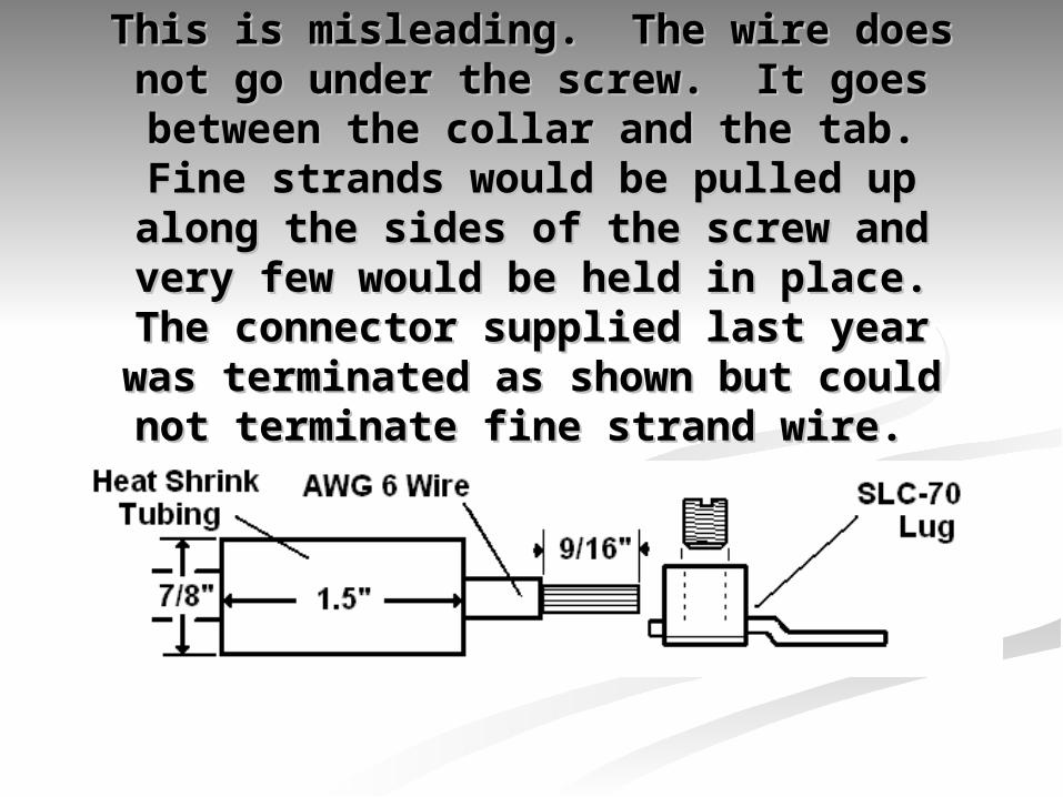
This is misleading. The wire does not This is misleading. The wire does not go under the screw. It goes between go under the screw. It goes between the collar and the tab. Fine strands the collar and the tab. Fine strands
would be pulled up along the sides of would be pulled up along the sides of the screw and very few would be held the screw and very few would be held in place. The connector supplied last in place. The connector supplied last
year was terminated as shown but year was terminated as shown but could not terminate fine strand wire. could not terminate fine strand wire.

8. The battery could 8. The battery could electrocute you, why do electrocute you, why do
we use it?we use it? The voltage generated by this battery The voltage generated by this battery is not capable hurting anyone due to is not capable hurting anyone due to direct contact. The battery can still direct contact. The battery can still cause harm if misused. Shorts cause harm if misused. Shorts across the terminals can generate across the terminals can generate high amounts of heat capable of high amounts of heat capable of burning anyone who touches it. I burning anyone who touches it. I have seen fires on the field and in the have seen fires on the field and in the pit due to shorting out the battery. pit due to shorting out the battery. Keep battery terminals insulated at Keep battery terminals insulated at all times.all times.

7. Battery connectors 7. Battery connectors are too small, are too small, underrated.underrated.
Although rated at 50 amps, the overall heat Although rated at 50 amps, the overall heat generated in the connector during a two generated in the connector during a two minute match is low enough that teams do minute match is low enough that teams do not need to worry. If the connector is not need to worry. If the connector is improperly crimped, damaged or improperly crimped, damaged or misaligned, or the robot design is misaligned, or the robot design is significantly inefficient, some heating of the significantly inefficient, some heating of the connector is possible and damage could be connector is possible and damage could be the result. I have seen little evidence of the result. I have seen little evidence of connector damage. Using alligator clips on connector damage. Using alligator clips on the charger to connect to the Anderson the charger to connect to the Anderson battery connector will damage the surface.battery connector will damage the surface.

6. The main battery 6. The main battery cannot be used lying cannot be used lying
down.down. The main battery can be used in any The main battery can be used in any orientation, including upside down. It orientation, including upside down. It can be charged in any direction except can be charged in any direction except upside down. Battery terminals must upside down. Battery terminals must be protected at all times and the be protected at all times and the battery must be secured in the robot. battery must be secured in the robot. You can’t play when your battery is You can’t play when your battery is lying on the field.lying on the field. Also don’t pick up Also don’t pick up the battery by the wires, as internal the battery by the wires, as internal damage will result.damage will result.

5. My four wheel drive 5. My four wheel drive robot eats batteries, robot eats batteries, there is something there is something wrong with control wrong with control
system.system.Four wheel or tank drive systems use Four wheel or tank drive systems use incredible amounts of current when turning incredible amounts of current when turning using high friction drive surfaces like belting using high friction drive surfaces like belting or knobby tires. When a robot turns it must or knobby tires. When a robot turns it must drag the wheels or treads sideways across drag the wheels or treads sideways across the carpet. In a tight or fast turn, this high the carpet. In a tight or fast turn, this high friction translates into near stall conditions friction translates into near stall conditions for all the drive motors. The result is for all the drive motors. The result is temporary current draw above 200 amps in a temporary current draw above 200 amps in a four motor drive. That may be enough to four motor drive. That may be enough to draw the voltage in the battery below RC draw the voltage in the battery below RC minimum.minimum.

4. The backup battery is 4. The backup battery is not used when the main not used when the main
power is shut off.power is shut off. According to the RC manual, Team LEDs According to the RC manual, Team LEDs (and the backup circuit in the RC) will (and the backup circuit in the RC) will shut down after four seconds if the RC has shut down after four seconds if the RC has not established contact with an OI not established contact with an OI connected to the arena controller. If an connected to the arena controller. If an arena controller is connected and a link arena controller is connected and a link has been established, the backup battery has been established, the backup battery will still be connected to everything on the will still be connected to everything on the robot for up to four minutes after main robot for up to four minutes after main power has been removed. With servos and power has been removed. With servos and LEDs, a lot of power is watsted. Press LEDs, a lot of power is watsted. Press reset after every power off.reset after every power off.

3. The battery has 3. The battery has memory and needs to be memory and needs to be
discharged to zero.discharged to zero. This is one of the most common This is one of the most common myths. It arises from a particular myths. It arises from a particular type of NiCad battery behavior. Gel type of NiCad battery behavior. Gel cell batteries do not have a memory cell batteries do not have a memory that needs any special handling. that needs any special handling. Charge them normally with the Charge them normally with the supplied chargers and never at more supplied chargers and never at more than 6 amps.than 6 amps.

2. The battery is too 2. The battery is too small.small.
The battery is actually very powerful. The battery is actually very powerful. Most teams have no problem driving a Most teams have no problem driving a 130 pound robot for more than two 130 pound robot for more than two matches with the kit battery. If your matches with the kit battery. If your robot drains a charged battery by the robot drains a charged battery by the end of a match, the mechanical design is end of a match, the mechanical design is inefficient or you are using some form of inefficient or you are using some form of tank drive. (treads or four or more non-tank drive. (treads or four or more non-steering drive wheels). In a hard match steering drive wheels). In a hard match or a restart, you may not have enough or a restart, you may not have enough battery reserve to last two minutes.battery reserve to last two minutes.

1. You don’t need to 1. You don’t need to calibrate speed calibrate speed
controllers.controllers.The biggest myth of all. Do not The biggest myth of all. Do not believe this one. The speed believe this one. The speed controller has the ability to adapt to controller has the ability to adapt to each joystick you use. Since each each joystick you use. Since each speed controller is not matched to speed controller is not matched to the joystick you were shipped, they the joystick you were shipped, they must be calibrated. Calibration gives must be calibrated. Calibration gives the controller the ability to match the the controller the ability to match the maximum travel on the joystick to the maximum travel on the joystick to the maximum output on the controller.maximum output on the controller.


![arXiv:1910.03676v1 [cs.CV] 8 Oct 2019 · arXiv:1910.03676v1 [cs.CV] 8 Oct 2019. Shade 1 Shade 2 Shade 3 Shade 4 Shade 5 Shade 6 1 0 Average Face per Shade Baseline VGG16 BR-Net VGG16](https://static.fdocuments.in/doc/165x107/5f06e0387e708231d41a2ca7/arxiv191003676v1-cscv-8-oct-2019-arxiv191003676v1-cscv-8-oct-2019-shade.jpg)