Firm 1 Annexure-3 Sl.No Clause No. Comment
82
Firm – 1 Annexure-3 Sl.No . Clause No. Stipulation as per Technical Specification Clarification / Confirmation DHBVN Comment Three Phase Oil Filled Distribution Transformers 1 14.4 The transformers shall be provided with terminal lugs/thimbles of approximate size on bushings both on HV Side & LV Side. Please provide HV & LV Sides Terminating Cable sizes in order to provide suitable terminal connectors. Will be finalized during detailed engineering. 2 15.O Off-Load Tap Changer (+5% to -7.5% in steps of 2.5%). As per IS 1180(Part 1): 2014, standard tapping range shall be +5% to -10% in steps of 2.5%. Please allow us to offer as per IS 1180(Part 1):2014. As per Amended Specification 3 17 All steel screws, nuts and fasteners exposed to atmosphere shall be either galvanized or cadmium plated. As per IS 1180(Part 1):2014, All bolts /Nuts/Washers exposed to atmosphere shall be as follows. Size 12 mm or below – stainless steel. Above 12 mm- steel with suitable finish like electro galvanized with passivation or hot dip galvanized We request you to provide your acceptance as per IS 1180(Part 1):2014. No Change - As per specifications 4 34.1 Internal HV Fuse on the HT Side of Transformer. As per IS 1180(Part 1):2014, HV Fuse is not applicable. Hence we request you to allow us to offer as per the IS 1180(Part 1):2014. As per Amended Specification Dry Type Transformers Sl. No. Clause No. Stipulation as per Technical Specification Clarification / Confirmation DHBVN Comment 5 6.1.ii Class C grade insulation paper of thickness 20mils (0.5mm) shall be used and make should be clearly stated in the offer along with test certificates. But for small LV voltage of 433V, core insulation is not required and also as our winding coil is casted/encapsulated type, the resin on conductor acts as insulation layer. Please send your acceptance to proceed further. As per Amended Specification 6 5.5.i Average winding temperature rise over an ambient temperature of 50 deg C shall not exceed 65 deg c by resistance method. Max. temperature of winding shall not exceed 115 deg C For dry type transformers, we would like to proceed as per IS11171 i.e. the temperature rise for “Class B” insulation shall be 70 deg C, for “Class F” insulation shall be 90 deg C and for “Class H” insulation shall be 115 degC over and ambient temperature of 50 deg C. Now, we request you to kindly confirm the winding temperature rise to be As per Amended Specification
Transcript of Firm 1 Annexure-3 Sl.No Clause No. Comment

Firm – 1 Annexure-3
Sl.No.
Clause No.
Stipulation as per Technical Specification Clarification / Confirmation DHBVN Comment
Three Phase Oil Filled Distribution Transformers
1 14.4 The transformers shall be provided with terminal lugs/thimbles of approximate size on bushings both on HV Side & LV Side.
Please provide HV & LV Sides Terminating Cable sizes in order to provide suitable terminal connectors.
Will be finalized during detailed engineering.
2 15.O Off-Load Tap Changer (+5% to -7.5% in steps of 2.5%). As per IS 1180(Part 1): 2014, standard tapping range shall be +5% to -10% in steps of 2.5%.
Please allow us to offer as per IS 1180(Part 1):2014.
As per Amended Specification
3 17 All steel screws, nuts and fasteners exposed to atmosphere shall be either galvanized or cadmium plated. As per IS 1180(Part 1):2014, All bolts /Nuts/Washers exposed to atmosphere shall be as follows. Size 12 mm or below – stainless steel. Above 12 mm- steel with suitable finish like electro galvanized with passivation or hot dip galvanized
We request you to provide your acceptance as per IS 1180(Part 1):2014.
No Change - As per specifications
4 34.1 Internal HV Fuse on the HT Side of Transformer. As per IS 1180(Part 1):2014, HV Fuse is not applicable. Hence we request you to allow us to offer as per the IS 1180(Part 1):2014.
As per Amended Specification
Dry Type Transformers
Sl. No.
Clause No.
Stipulation as per Technical Specification
Clarification / Confirmation DHBVN Comment
5 6.1.ii Class C grade insulation paper of thickness 20mils (0.5mm) shall be used and make should be clearly stated in the offer along with test
certificates.
But for small LV voltage of 433V, core insulation is not required and also as our winding coil is casted/encapsulated type, the resin on conductor acts as insulation layer. Please send your acceptance to proceed further.
As per Amended Specification
6 5.5.i Average winding temperature rise over an ambient temperature of 50 deg C shall not exceed 65 deg c by resistance method. Max. temperature of winding shall not exceed 115 deg C
For dry type transformers, we would like to proceed as per IS11171 i.e. the temperature rise for “Class B” insulation shall be 70 deg C, for “Class F” insulation shall be 90 deg C and for “Class H” insulation shall be 115 degC over and ambient temperature of 50 deg C. Now, we request you to kindly confirm the winding temperature rise to be
As per Amended Specification

considered.
7 1.1 The specification covers design manufacture, testing, packing and delivery of 3phase 50 Hz, dry type (VPI)
These two clauses are contradicted. Please note that, we shall only manufacture casted coils (Encapsulated) type dry type transformers. Hence, we request you to kindly accept our proposal. However, If VPI coil type dry type transformers are mandatory; we regret to submit our quotation, accordingly.
As per Amended Specification
8 6.6 H.V and L.V coil shall be fully encapsulated type
As per Amended Specification
9 6.6.iii HV and LV coil insulated with class C insulation paper with vacuum pressure impregnated process in varnish.
Please note that, No impregnation process will be done as our manufacturing system is of Encapsulated type only. Further to the above, super enamel/ fiber covered conductors shall only be used for insulation of HV and LV coils. Kindly send your confirmation.
As per Amended Specification
10 6.6.iii Winding design shall be adequate to allow for full encapsulated with filled resin r conforming to class H
Please note that, we manufacture dry type transformers without filler material during casting of the HV and LV coils, respectively i.e. Unfilled casting system. We request you to kindly accept our proposal. However, if Filler material is mandatory; we regret to submit quotation, accordingly.
No Change - As per specifications
11 6.7 Current density for HV and LV winding should not be more than 1.4a/sq.mm
We request you to kindly remove the current density restriction. However, we here by guarantee that, transformer shall be designed without exceeding specified losses as mentioned in the technical specification.
As per Amended Specification
12 6.10 The enclosure should comply with IP 43 protection class
Please note that, for indoor use, IP21 protection class is adequate. Hence, we request you to kindly accept our proposal.
No Change - As per specifications
13 6.9.b The thickness of locking spacers and thickness of comb teeth between HV disc
This is not applicable for cast resin transformers. Hence, kindly remove this from specification.
As per Amended Specification
14 6.11.7 Paints Powder coating for inside and outside (or) Hot oil for inside and polyurethane for outside
Please note that for Dry type transformers, inside and outside paint shall be same only. Hence, we request you to kindly allow us to proceed with either powder coating or polyurethane.
No Change - As per specifications
15 6.10 Top cover fixing bolts This is not applicable for dry type transformers as the transformer is housed in an Enclosure as per our standard practice. Kindly accept our proposal.
As per Amended Specification
16 3.1.xii Seismic zone - 4 Please re-confirm the requirement of seismic zone 4 as it requires special attention to withstand forces/strokes. If is
No Change - As per

Firm -2
Sl. No.
Clause No. Clause Description / Summary Request for Clarity / Ammendment along with Justification
DHBVN Reply/Comments
RMU
1 Clause No. 1 Scope (page 3 of 24)
Specification asked for 11kV RMU with inbuilt FPI & FRTU (of same manufacturer)
Firm does not have required FPI of its own make. Hence, request you to allow quote of RMU with third-party make FPI. Offered FPI will be fully integrable with RMU, and Firm will offer performance warranty of equipment thus offered. Further, as specifications call for use of open-protocol communication (such as ModBus or IEC-103) of FRTU with SCADA as well as RMU, there is no necessity of proprietary relationship which technically requires RMU and FRTU be of same make. To invite fair competition, and arrive at techno-commercially most feasible solution, we request you to allow us to use RTUs of other makes as well.
As per Amended Specification
2 Clause No. 4 (1.) Climatic Conditions (page 4 of 24)
Maximum ambient air temperature: 50 deg C
Please consider that RMU has been designed for rated current of 630A at 40 deg C maximum average ambient temperature. Current deration to the tune of 5-10% shall need to be applied for average ambient temperature of 50 deg C. Considering the DHBVN norms related to ring connectivity, we anticipate that maximum current routed via RMU shall be adequately borne by it even under
As per Amended Specification
mandatory to meet the seismic zone 4 requirements, we shall guarantee the same by providing necessary additional fittings accordingly. However, no test shall be performed to confirm the seismic zone 4 requirement. Please send your acceptance.
specifications
17 Apart from above said details, some other clauses are not applicable for Dry type transformers as this is different from oil filled type transformers. Hence we shall consider only those clauses which are applicable for Dry type transformers and shall proceed as per our standard practice. Please confirm.
As per IS 11171 / IEC 60076-11:2004

derated conditions. Accordingly, please accept the same.
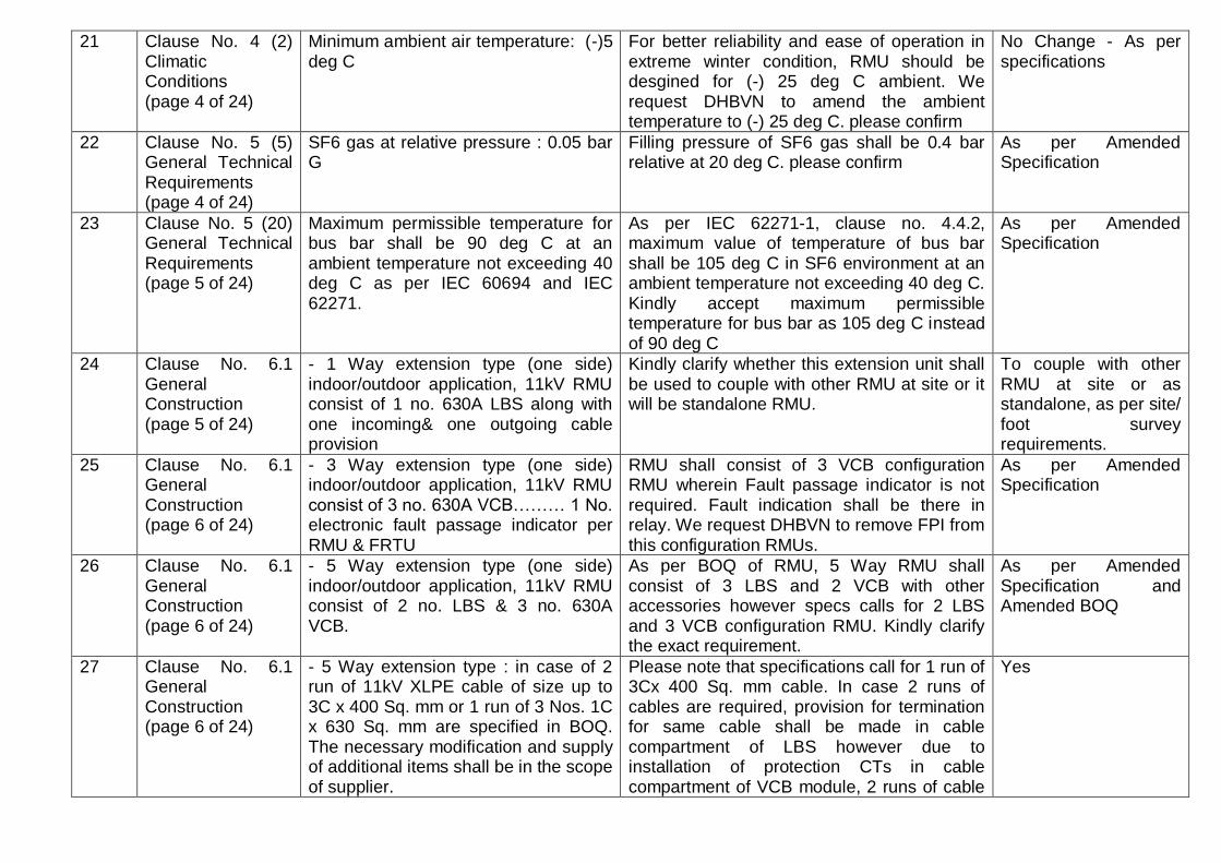
3 Clause No. 4 (2.) Climatic Conditions (page 4 of 24)
Minimum ambient air temperature: (-)5 deg C
For better reliability and ease of operation in extreme winter condition, RMU should be desgined for (-) 25 deg C ambient. We request DHBVN to amend the ambient temperature to (-) 25 deg C
No Change - As per specifications
4 Clause No. 5 (5.) General Technical equirements (page 4 of 24)
SF6 gas at relative pressure : 0.05 bar G
Gas pressure inside the RMU is as per manufacturer specific design, and should be sufficient to meet the insulation level requirements associated with 11kV system. For offered design of RMU, filling pressure of SF6 gas shall be 0.4 bar relative at 20 deg C. Request you to accept the same.
As per Amended Specification
5 Clause No. 5 (20.) General Technical equirements (page 5 of 24)
Maximum permissible temperature for bus bar shall be 90 deg C at an ambient temperature not exceeding 40 deg C as per IEC 60694 and IEC 62271.
As per IEC 62271-1, clause no. 4.4.2, maximum value of temeparure of bare-copper / silver-plated copper contacts bar shall be 105 deg C in SF6 environment at an ambient temperature not exceeding 40 deg C. Kindly accept maximum permissible temperature as 105 deg C instead of 90 deg C It may be noted that Firm confirms use of either bare-copper or silver-plated electrolytic grade bare copper contacts inside the gas-tank, as the same is assured of oxygent free environment throughout the operational life of the equipment.
As per Amended Specification
6 Clause No. 6.1 General Construction (page 5 of 24)
- 1 Way extension type (one side) indoor/outdoor application, 11kV RMU consist of 1 no. 630A LBS along with one incoming& one outgoing cable provision
Kindly clarify whether this extension unit shall be used to couple with other RMU at site or it will be standalone RMU.
To couple with other RMU at site or as standalone, as per site/ foot survey requirements.
7 Clause No. 6.1 General Construction (page 6 of 24)
- 3 Way extension type (one side) indoor/outdoor application, 11kV RMU consist of 3 no. 630A VCB……… 1 No. electronic fault passage indicator per RMU & FRTU
Note that where RMU shall consist of 3 VCB configuration, Fault passage indicator is not required as fault indication shall be there in relay. DHBVN to consider and confirm please.
As per Amended Specification
8 Clause No. 6.1 General Construction (page 6 of 24)
- 5 Way extension type (one side) indoor/outdoor application, 11kV RMU consist of 2 no. LBS & 3 no. 630A VCB.
As per BOQ of RMU, 5 Way RMU shall consist of 3 LBS and 2 VCB with other accessories however specs calls for 2 LBS and 3 VCB configuration RMU. Kindly clarify the exact requirement.
As per Amended BOQ
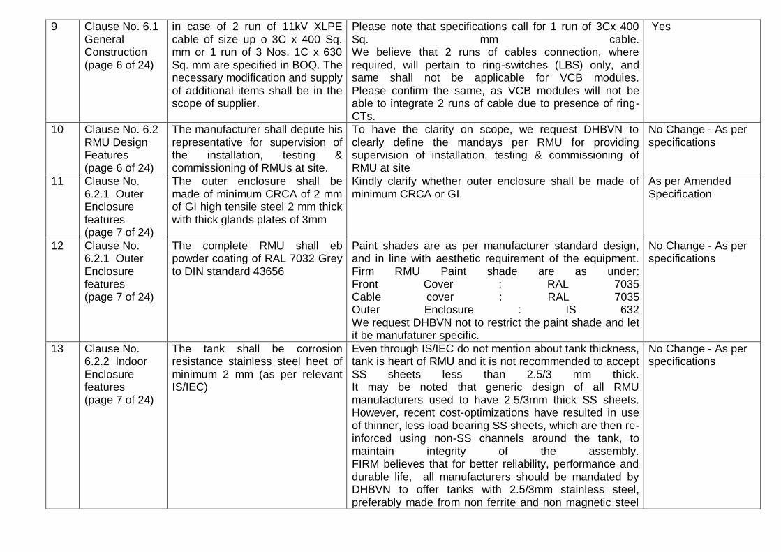
9 Clause No. 6.1 General Construction (page 6 of 24)
in case of 2 run of 11kV XLPE cable of size up o 3C x 400 Sq. mm or 1 run of 3 Nos. 1C x 630 Sq. mm are specified in BOQ. The necessary modification and supply of additional items shall be in the scope of supplier.
Please note that specifications call for 1 run of 3Cx 400 Sq. mm cable. We believe that 2 runs of cables connection, where required, will pertain to ring-switches (LBS) only, and same shall not be applicable for VCB modules. Please confirm the same, as VCB modules will not be able to integrate 2 runs of cable due to presence of ring-CTs.
Yes
10 Clause No. 6.2 RMU Design Features (page 6 of 24)
The manufacturer shall depute his representative for supervision of the installation, testing & commissioning of RMUs at site.
To have the clarity on scope, we request DHBVN to clearly define the mandays per RMU for providing supervision of installation, testing & commissioning of RMU at site
No Change - As per specifications
11 Clause No. 6.2.1 Outer Enclosure features (page 7 of 24)
The outer enclosure shall be made of minimum CRCA of 2 mm of GI high tensile steel 2 mm thick with thick glands plates of 3mm
Kindly clarify whether outer enclosure shall be made of minimum CRCA or GI.
As per Amended Specification
12 Clause No. 6.2.1 Outer Enclosure features (page 7 of 24)
The complete RMU shall eb powder coating of RAL 7032 Grey to DIN standard 43656
Paint shades are as per manufacturer standard design, and in line with aesthetic requirement of the equipment. Firm RMU Paint shade are as under: Front Cover : RAL 7035 Cable cover : RAL 7035 Outer Enclosure : IS 632 We request DHBVN not to restrict the paint shade and let it be manufaturer specific.
No Change - As per specifications
13 Clause No. 6.2.2 Indoor Enclosure features (page 7 of 24)
The tank shall be corrosion resistance stainless steel heet of minimum 2 mm (as per relevant IS/IEC)
Even through IS/IEC do not mention about tank thickness, tank is heart of RMU and it is not recommended to accept SS sheets less than 2.5/3 mm thick. It may be noted that generic design of all RMU manufacturers used to have 2.5/3mm thick SS sheets. However, recent cost-optimizations have resulted in use of thinner, less load bearing SS sheets, which are then re-inforced using non-SS channels around the tank, to maintain integrity of the assembly. FIRM believes that for better reliability, performance and durable life, all manufacturers should be mandated by DHBVN to offer tanks with 2.5/3mm stainless steel, preferably made from non ferrite and non magnetic steel
No Change - As per specifications

properties. It can be fairly established that such design is available and has been supplied by relevant manufacturers nationally as well as internationally.
14 Clause No. 6.2.4 (page 8 of 24)
The RMU shall be with all connection and with tinned copper
All conductor inside the tank of RMU is made from electrolytic grade copper, where further silver plating is done on movable contacts. As the complete environment inside SS tank is completely oxygen free, tinned copper is not an essential requirement. Hence, request you to suitably ammend the clause.
As per Amended Specification
15 Clause No. 6.4 Circuit Breakers (page 10 of 24)
The circuit breaker…………………shall include three toroid transformer incorporated in the transformer tee-off bushing.
Protection and metering transformers shall be of resin cast and shall be installed in cable compartment over cable, as they are easy to access for O&M and testing purposes. CTs installation on bushing, is manufacturer/design specific, hence please do not make the same mandatory.
No change in technical specifications. The toroid T/Fs are a part of the protection unit
16 Clause No. 6.4 Circuit Breakers (page 10 of 24)
The CT setting shall be adjustable between 600 to 300/5A
CTs rating can be anything rating between 600 to 300/1A, however protection relay shall have setting range O/C from 20% to 200% to achieve tripping on fault. Secondary rating of CTs shall be 1A. Please be advised that use of unnecessarily high CT-Ratio can result in loss of sensitivity at lower load current. We recommend that CT-Ratio selection may be left to EPC/manufacturer recommendation depending on load survey done post award.
As per Amended Specification
17 Clause No. 6.6 CTs and PTs (page 11 of 24)
Appropriate capacity CTs & PTs shall be provided in the RMU for the metering purpose with the provision to provide the inputs to the FTRU for remote SCADA/DMS/OMS functionality. The meter shall not be in the scope of supplier however the provision and space for installation of the same in future shall be available in the seperate enclosure for housing the battery/charger etc.
Kindly confirm the provision of metering is required for which feeder? We anticipate that metering will be required for VCB feeders. DHBVN to confirm the same. Further, please advise on tentative cut-out/space required or the recommended make/models of meters so that adequate space can be provided.
- The metering is not required for feeder. -Refer DHBVN specification of DT meter available on www.dhbvn.org.in

18 Clause No. 6.9 Earthing (page 13 of 24)
The RMU outdoor metal clad We clarify that RMU shall be outdoor metal enclosed type. No Change - As per specifications
19 Clause No. 6.9 Earthing (page 13 of 24)
The size of earth bus bar of GI strip (75 x 12 sq. mm) shall be provided……. Provision shall be made on the end of RMU for connecting the earth bus to earth grid by erecting suitable 2 earth pipes of.... ..to be connected in grid formation
GI earthing is not feasible inside the RMU, as it will not be feasible to accomodate 75x12 = 900sqmm cross-section of GI inside the compact design of RMU. We request DHBVN to amend the earth bus to Coppper of 30 x 4 = 120 Sqmm. which can also result in better performance, reliability and life. External to RMU, GI earthing can be provided by contractor owing to anti-theft requirements.
As per Amended Specification
20 Clause No. 6.13 Motors (page 14 of 24)
The max current drawn shall be 9 amp (+/- 10%)
Peak current of motor shall be 14 amp, and control/isolation circuit has been designed accordingly.
No Change - As per specifications
21 Clause No. 6.14 Power Supply, Battery & Charger (page 14 of 24)
There shall be provision of installation of FRTU, CT/PT, energy meters in future
Please confirm whether FRTU, CT/PT, energy meters are part of present scope or future provision.
The energy meters are not in the scope of contractor
22 Clause No. 6.14 Power Supply, Battery & Charger (page 14 of 24)
The auxiliary power transformer's input shall be equipped with surge protection device
Owing to highly compact design of RMU, is not feasible to install any surge protection device due to space constraints. However, we will provide HRC fuses for isolation on HT-side. We request DHBVN to remove this requirement
No Change - As per specifications
23 Clause No. 7 Paint (page 15 of 24)
The enclosure of the RMU shall be painted with RAL 7032 Grey . RMU Paint shade shall be as under: Front Cover : RAL 7035 Cable cover : RAL 7035 Outer Enclosure : IS 632 We request DHBVN not to restrict the paint shade and let it open for all manufaturer.
Paint shades are as per manufacturer standard design, and in line with aesthetic requirement of the equipment. FIRM RMU Paint shade are as under: Front Cover : RAL 7035 Cable cover : RAL 7035 Outer Enclosure : IS 632 We request DHBVN not to restrict the paint shade and let it be manufaturer specific.
No Change - As per specifications
24 Clause No. 9.4 Acceptance test
Heat run test shall be carried out on one random sample/configurations/tender
We request that temperature rise test (Heat run test) is a type test which has already been carried out on offered design of RMUs. Type test reports shall be furnish with
No Change - As per specifications

(page 17 of 24) quantity as acceptance test. bid. Accordingly, please re-consider whether the same needs to be re-conducted as it will necessiate re-curring cost and time-delay. It may be noted that owing to extremely tight deadline (18-months), such delays may affect project schedule severely.
25 Clause No. 9.4 Acceptance test (page 17 of 24)
In additon SCADA operations in the RMU along with FRTU should be demonstrated during factory inspection in manufacturer's own labs failing which the supplies shall not be accepted. RMU and FTRUs are two different products which are getting manufatured in different factories. Integration of FRTU in RMU shall be done at site by respective manufacturer. SCADA operations in the RMU along with FRTU should be demonstrated during factory inspection is not feasible. We request DHBVN to remove this test from acceptance test.
Please give contractor the option to demonstrate SCADA operations at site, as normally RMU and FRTUs are manufactured at separate location. Accordingly, it may not be deasible to always demonstrate the same as part of routine inspection. Such demonstration can be arranged once at works as part for prototype approval.
No Change - As per specifications
26 Clause No. 9.4 (a) Acceptance test (page 17 of 24)
Facility for primary current injection up to 1000A
Note that primary injection is done thru bushing only hence primary injection current shall be limited to rated current only i.e 630A max.
No Change - As per specifications
27 Clause No. 9.4 (a) Acceptance test (page 17 of 24)
Pre-commissioning test to be conducted on each RMU before installations and commissioning
Please confirm that pre-commissioning test can be done by contractor.
No Change - As per specifications
28 Clause No. 16 Spares, Accessories & Special tools/Gauges (page 18 of 24)
Autochangeover in-built requirement utilization VPIS or through separate core of PT proposed on each breaker along with assocoatedcircutiry.
Auto-changeover is relatively complex logic, requiring various safety interlocks and feedbacks to be implemented. We recommend that same be implemented at SCADA level rather than local level as it may result in un-safe/un-expected/nuisance operation if not implemented properly. If same is required to be implemented, DHBVN is
As per Amended Specification

requested to elaborate the algorithm to be adopted along with safety checks where applicable.Please confirm.
29 Clause No. 18 Challenge clause (page 20 of 24)
Material shall be dispatched only after successful inspection and getting dispatch clearance. Un acceptance at site after inspection and then paying penalty of 10% is not feasible. We request DHBVN to re-look into the same.
No Change - As per specifications
30 Clause No. 19 Warrantee Period (page 20 of 24)
Warranty of 72 months from the date of commissioning
1. Supplier shall repair or replace at their option, free of cost, on ex - works basis the whole or any portion of material/ equipment which under normal and proper use and maintenance proves defective in material and/ or workmanship within 60 months from the date of commissioning or 66 months from the date of shipment of equipment which¬ever is earlier, provided prompt notice is given of such defects. If there is any delay in commissioning for any reason not attributable to the supplier for more than 15 days, the supplier shall issue 07 day’s notice to the purchaser to commission the equipment. Failure to comply the notice of the supplier by the purchaser, the equipment shall be deemed to have been commissioned from the date of notice and warranty period shall commence w.e.f. date of the notice of the supplier. It is further understood that repair and/or replacement of the defective equipment shall be the sole and exclusive remedy available to the purchaser. 2. Such replacements will be effected within a reasonable time actually required to do so. 3. Supplier liability arising out of supply¬ing the material or its use, whether on warranties or otherwise shall not in any case extend the warranty period and shall not exceed the cost of correcting the defects or replacement of the defective material/ equipment and upon expiration of the period mentioned above, all such liability shall terminate. Supplier liability does not extend to consequential damages, either direct or indirect or expenses for repairs or replacements or otherwise paid or incurred without our authority. We accept no liability for defects or depreciation caused by damage in trans¬it, lightning,
No Change - As per specifications
dampness, neglect, misuse/ negligent actions or omissions, inadequate storage, other abnormal conditions due directly or indirectly to circumstances beyond our control. 4. Further warranty will not be applicable in case of (a) Equipment failure due to misuse, abuse, man handling etc. (b) Equipment being repaired/ rectified/ tampered without supplier prior permission. (c) Equipment’s or parts of Equipment subject to normal wear and tear. The warranty contained herein shall be void at supplier discretion, in the event of breach of the contractual terms and conditions by purchaser, including non-payment of consideration or servicing of the switchgear by a person or agency not authorised by supplier
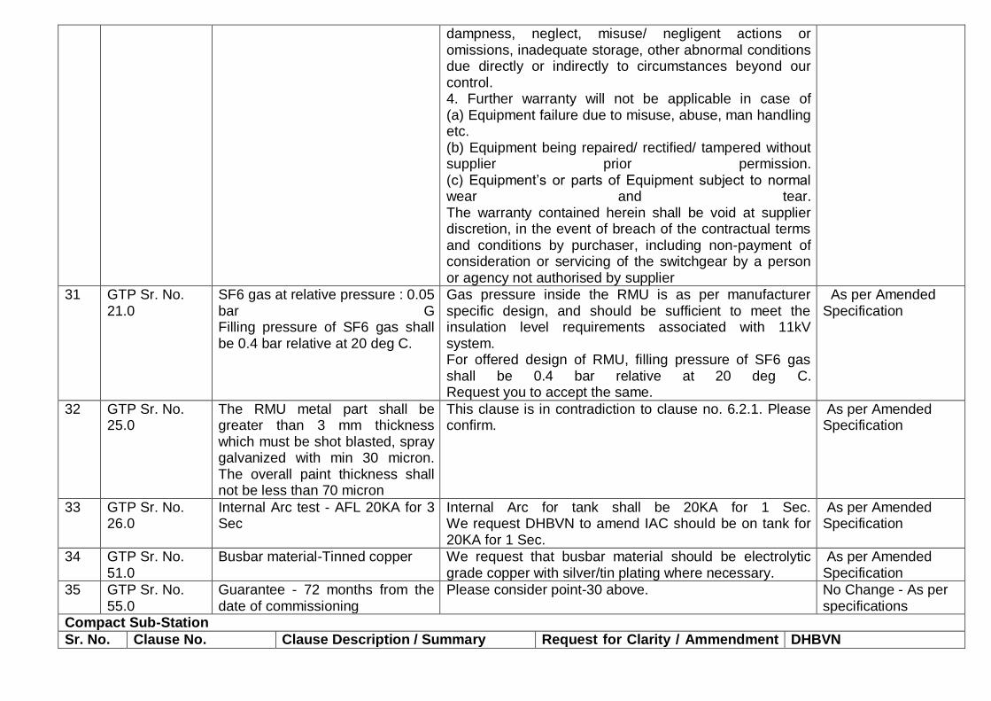
31 GTP Sr. No. 21.0
SF6 gas at relative pressure : 0.05 bar G Filling pressure of SF6 gas shall be 0.4 bar relative at 20 deg C.
Gas pressure inside the RMU is as per manufacturer specific design, and should be sufficient to meet the insulation level requirements associated with 11kV system. For offered design of RMU, filling pressure of SF6 gas shall be 0.4 bar relative at 20 deg C. Request you to accept the same.
As per Amended Specification
32 GTP Sr. No. 25.0
The RMU metal part shall be greater than 3 mm thickness which must be shot blasted, spray galvanized with min 30 micron. The overall paint thickness shall not be less than 70 micron
This clause is in contradiction to clause no. 6.2.1. Please confirm.
As per Amended Specification
33 GTP Sr. No. 26.0
Internal Arc test - AFL 20KA for 3 Sec
Internal Arc for tank shall be 20KA for 1 Sec. We request DHBVN to amend IAC should be on tank for 20KA for 1 Sec.
As per Amended Specification
34 GTP Sr. No. 51.0
Busbar material-Tinned copper We request that busbar material should be electrolytic grade copper with silver/tin plating where necessary.
As per Amended Specification
35 GTP Sr. No. 55.0
Guarantee - 72 months from the date of commissioning
Please consider point-30 above. No Change - As per specifications
Compact Sub-Station
Sr. No. Clause No. Clause Description / Summary Request for Clarity / Ammendment DHBVN

along with Justification Reply/Comments
36 BOQ General Description of BOQ Please confirm that RMU provided inside the CSS has to be integrated with FRTU/FPI as per nigam specifications for RMU.
Yes
37 BOQ General Description of BOQ Please clarify in detail what is meant by separate DT metering Compartment, whether only space provision in LT compartment (inside CSS ) is to be provided and what will be the dimension of the meter(technical details of the meter like class of accuracy etc), whether same has to be considered in our scope of supply.
Only space provision for meter to be given. For specification of meter please refer nigam’s tech specs available on www.dhbvn.org.in
38 BOQ, Clause 5.1.2 General Description of BOQ As per rating of transformer, 630kVA and 400kVA the LT Busbar rating is given as 1600 Amps in the BOQ and 1250A and 800A are mentioned in the specification. Please clarify regarding rating to consider.
As per Amended BOQ
39 Technical Specification - Clause Number 4.0 point number 11 and 5.1.1
Minimum thickness of sheet a) Sides - 2 mm b) Base - 4 mm
Offered CSS shall be a type tested design according to latest IEC 62271-202 and shall have 1.5 mm thick non load bearing members and 2 mm thick load bearing members with a base frame of 4mm. FIRM has supplied this design of CSS to various utilities across country. Please accept the same.
No Change - As per specifications
40 Technical Specification - Clause Number 4.0 point number 11
Maximum permissible temperature rise for the bus bar and terminals shall be 45 deg C & 65 deg c respectively, at ambient not exceeding 40 deg. C.
This we assume is for LT Panel inside CSS, for which all the limits of Temperature rise shall be as per IEC 61439.
As per Amended Specification
41 Technical Specification - Clause Number 4.0
Colour shade - PENTON E2727C We offer DA Gray , Light Gray CSS with shades nearer to RAL 7035 for Enclosure and for roof it shall be
No Change - As per specifications

point number 15 nearer to IS 632.
42 Technical Specification - Clause Number 4.0 B (RMU) point number 2
RMU Application - Containerized By Containerised RMU we understand it is indoor modular compact switchgear placed inside CSS with IP54 compartment for HT. Please confirm.
No Change - As per specifications
43 Technical Specification - Clause Number 4.0 B (RMU) point number 16,17
Opening time of breaker (max.) - 2.5 Cycle Closing Time of breaker (max.) - 3 Cycle
Kindly note that Opening Time of breaker - (approx 40 - 80 ms) Closing Time of breaker - (approx 40 - 70 ms)
No Change - As per specifications
44 Technical Specification - Clause Number 4.0 B (RMU) point number 21
Min Gas pressure - 0.05 Bar G Gas pressure inside the RMU is as per manufacturer specific design, and should be sufficient to meet the insulation level requirements associated with 11kV system. For offered design of RMU, filling pressure of SF6 gas shall be 0.4 bar relative at 20 deg C. Request you to accept the same.
As per Amended Specification
45 Technical Specification - Clause Number 4.0 B (RMU) point number 25
IP 67 for the tank and IP2X for the front cover /mimic board and IP54 for Outdoor RMUs. The RMU metal parts shall be greater than 3mm thickness high tensile steel which must be shot blasted, spray galvanized with minimum thickness of 30 micron and subsequently powder coated. The overall paint thickness shall be not less than 70 microns
SF6 tank shall be made up of stainless steel SS 304 grade with thickness 2.5 mm and Enclosure made up of 2 mm thick CRCA which shall be duly powder coated followed by 7 tank process which shall have paint thickness of 60-80 microns
As per Amended Specification
46 Technical Specification - Clause Number 4.0 B (RMU) point number 26
Internal Arc -AFL 20 KA for 3 sec. Internal arc for RMU shall be 20kA for 1 second however STC shall be 21kA for 3 seconds.
As per Amended Specification
47 Technical Specification - Clause Number 4.0
As per specification - The size of earth bus bar of GI strip (75
GI earthing is not feasible inside the RMU, as it will not be feasible to accomodate 75x12 = 900sqmm
As per Amended Specification

B (RMU) point number 31
x 12 sq. mm) shall be provided……. Provision shall be made on the end of RMU for connecting the earth bus to earth grid by erecting suitable 2 earth pipes of.... ..to be connected in grid formation
cross-section of GI inside the compact design of RMU. We request DHBVN to amend the earth bus to Coppper of 30 x 4 = 120 Sqmm. which can also result in better performance, reliability and life.
48 Technical Specification - Clause Number 4.0 B (RMU) point number 32
Earthing of main CCT Cables shall be earthed with earth switch with. S/C making capacity as per I EC 129. Moving contacts of earthing switch shall be visible in closed position via transparent covers.
All live parts are enclosed inside robotically welded stainless steel tank hence visibility of moving contacts of earth switch shall not be applicable. However, true-position indication shall be provided. Please clarify what do you mean by "Earthing of main CCT Cables shall be earthed via earth switch with Short circuit making capacity as per IEC 129"
As per Amended Specification
49 Technical Specification - Clause Number 4.0 B (RMU) point number 35
Self-powered relay with O/C IDMT characteristic with minimum PSM-0.2 JMS-0.01 +E/F IDMT characteristic with minimum PSM JMS -0.01 Hi-set setting for O/C + E/F min setting 0.5 in and delay 20 ms
We offer self-powered microprocessor based (3 O/C + 1 E/F Relay) with setting range as 20% to 200% for Overcurrent and 10% to 80% for earth fault protection) . This is as per Clause 6.7 of Nigam Specifications for RMU.
As per Amended Specification
50 Technical Specification - Clause Number 4.0 B (RMU) point number 38
Testing of Cable- without opening the doors. If doors are opened then earth switch shall be in closed position and cable test rod shall be provided which can be fixed on terminations for testing purpose and it shall not be possible to operate, E/Switch or CB
Cable testing facility shall be available only after opening the cable cover however same shall be possible without dismantling the cable termination.
No Change - As per specifications
51 Technical Specification - Clause Number 4.0 B (RMU) point number 39
Design of RMU shall be tamper & arc proof. Anti vandal screws shall be provided. Cable covers shall be pad lockable. All live parts / test bushings etc. shall be
We understand same shall not be applicable for RMU inside the CSS, which will be inside locale HT compartment with IP54 degree of ingress protection,
No Change - As per specifications

covered with antitheft covers.
52 Technical Specification - Clause Number 4.0 B (RMU) point number 42
Phase Comparator - 1 per RMU 1 Number Phase comparator shall be provided for entire lot of CSS.
No Change - As per specifications
53 Technical Specification - Clause Number 4.0 B (RMU) point number 51
Busbar material -Tinned Copper We request that busbar material should be electrolytic grade copper with silver/tin plating where necessary.
As per Amended Specification
54 Technical Specification - Clause Number 4.0 B (RMU) point number 55
Guarantee - 72 months from the date of commissioning
Offered CSS shall have warranty 60 months from date of commissioning or 66 months from date of supply which ever is earlier. Please accept the same.
No Change - As per specifications
55 Technical Specification - Clause Number 4.0 B (RMU) point number 58
Colour Shade -Dark Gray as per RAL 7032
Offered RMU shall have paint shade of RAL 7035
No Change - As per specifications
56 Technical Specification - Clause Number 4.0 B (RMU) point number 62
Earth Switch operation counter Mechanical Counter for earth switch is not feasible. However, same can be implemented by SCADA contractor over SCADA.
No Change - As per specifications
57 Technical Specification - Clause Number 4.0 C(Transformer) point number 1
Application - Container The Transformer shall be placed inside compartment of IP23 degree of ingress protection of the CSS.
No Change - As per specifications
58 Technical Specification - Clause Number 4.0 C(Transformer) point number 5
Rated Voltage LV - 433 V-250V The Transformer shall have rating as per BOQ as 11kV/0.433kV only. 250V LV shall not be applicable.
As per Amended Specification
59 Technical Specification -
Noise level at rated voltage and frequency - 57 db
The Transformer noise level shall be as per relevant IS/IEC/NEMA levels.
No Change - As per specifications

Clause Number 4.0 C(Transformer) point number 13
60 Technical Specification - Clause Number 4.0 C(Transformer) point number 14
Permissible temperature rise over ambient i) Of top oil measured by thermometer - 35 degrees ii)Of winding measured by resistance - 40 degrees
As per the latest IS 1180 amendment for transformers the temperature rise to be considered for Oil/Winding is 40/45 degrees over ambient.
No Change - As per specifications
61 Technical Specification - Clause Number 4.0 C(Transformer) point number 24
Neutral Terminal - Two separate brought out neutral from main neutral bus bar, One for taking out the neutral for 4 wire system and other additional neutral for solid earthing.
Please clarify in detail the requirement of neutral terminal.
No Change - As per specifications
62 Technical Specification - Clause Number 4.0 C(Transformer) point number 25
Minimum clearances in air for bushing terminals a) HV phase to phase/ phase to earth (mm) - 255/140 b) LV phase to phase/ phase to earth (mm) - 75/40
Clearances shall be as per CBIP norms.
No Change - As per specifications
63 Technical Specification - Clause Number 4.0 C(LV Compartment) point number 1
Maximum current density of bus bar 8 Amp./sq mm
We read Current density of bus bars as 0.8 A /sq.mm
It is clarified that the Current density of busbar is 0.8 A/sq mm
64 Technical Specification - Clause Number 4.0 C(LV Compartment) point number 2 , 16
Maximum permissible temperature rise 80 Deg C at terminals with an ambient temperature not exceeding 40 deg C
Maximum Temperature rise limits shall be as per IEC 61439.
As per amended specification
65 Technical Specification - Clause Number 4.0 C (a)(LT ACB) point number 19
Overloading current with time setting 40 to 100 % with function disable (off) option Time setting (tr) from – 1s,2s,4s to ... 24 sec
Time setting and disable option shall be as per manufacturer standard.
No Change - As per specifications
66 Technical Specification -
Earth Fault Setting with time 20% to 70% with function disable (off) option
Time setting and disable option shall be as per manufacturer standard.
As per Amended Specification

Clause Number 4.0 C (a)(LT ACB) point number 20, 21,22
Time Setting – 100ms to 400ms
67 Technical Specification - Clause Number 4.0 C (c)(LT MCCB) point number 17
For MCCB of 400 A & 630 A -With the help of external relay of sensitivity from 10% to 60% of rated current (In) and time selection from 500ms to 3000ms
We can offer Earth fault release along with the MCCB with in built Earth fault release with setting range from 20% to 100% rated current and time setting from 0.1 to 0.8 seconds in steps of 0.01 seconds.
No Change - As per specifications
68 Technical Specification - Clause Number 5.1.2
The transformer shall be of 11/0.433 kV, 400,500,630 & 1000kVA, hermetically sealed with corrugated tank construction. The LV compartment shall comprise of one no. 800 A ACB with 3 nos., 400A each MCCB for 400 kVA transformer, 800 A ACB with 3 nos., 400A each MCCB for 500 kVA, one no. 1250 A ACB with 4nos., 400A each MCCB for 630kVA transformer &1600 A ACB with 5 nos. 400A each MCCB for 1000kVA other auxiliary components with interconnections required for the complete operation of the sub-station
BOQ and subject clause contradict each other, kindly clarify the number of Outgoings in the LT panel side.
As per amended BOQ
69 Technical Specification - Clause Number 5.1.4
HV and LV compartments shall be accessible on the sides of the substation through double doors equipped with key lock and nitrile rubber seal. Transformer chamber door can be opened by accessing from the door arrangement from LT compartment.Two No. lifting arrangements shall be provided on both sides of transformer chamber
Neoprene rubber gasket shall be used for sealing of doors. The access to transformer compartment shall be through separate doors with pad lock arrangement and not interlocked with LT chamber. Bucket type lifting shall be provided for the entire CSS and not transformer compartment alone.
As per Amended Specification
70 Technical Specification - Clause Number 5.1.5
There shall be an arrangement for internal lighting activated by associated switch on doors for HV, Transformer and LV compartments separately
The hooter shall be placed only in transformer compartment with limit switch. Light activated through proper switch in transformer compartment
No Change - As per specifications
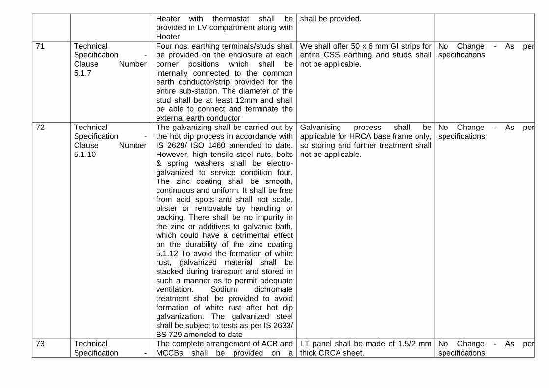
Heater with thermostat shall be provided in LV compartment along with Hooter
shall be provided.
71 Technical Specification - Clause Number 5.1.7
Four nos. earthing terminals/studs shall be provided on the enclosure at each corner positions which shall be internally connected to the common earth conductor/strip provided for the entire sub-station. The diameter of the stud shall be at least 12mm and shall be able to connect and terminate the external earth conductor
We shall offer 50 x 6 mm GI strips for entire CSS earthing and studs shall not be applicable.
No Change - As per specifications
72 Technical Specification - Clause Number 5.1.10
The galvanizing shall be carried out by the hot dip process in accordance with IS 2629/ ISO 1460 amended to date. However, high tensile steel nuts, bolts & spring washers shall be electro-galvanized to service condition four. The zinc coating shall be smooth, continuous and uniform. It shall be free from acid spots and shall not scale, blister or removable by handling or packing. There shall be no impurity in the zinc or additives to galvanic bath, which could have a detrimental effect on the durability of the zinc coating 5.1.12 To avoid the formation of white rust, galvanized material shall be stacked during transport and stored in such a manner as to permit adequate ventilation. Sodium dichromate treatment shall be provided to avoid formation of white rust after hot dip galvanization. The galvanized steel shall be subject to tests as per IS 2633/ BS 729 amended to date
Galvanising process shall be applicable for HRCA base frame only, so storing and further treatment shall not be applicable.
No Change - As per specifications
73 Technical Specification -
The complete arrangement of ACB and MCCBs shall be provided on a
LT panel shall be made of 1.5/2 mm thick CRCA sheet.
No Change - As per specifications

Clause Number 5.2.3
framework of channels with adequate strength to support the weight of the ACB and MCCB’s. The Framework shall be covered from the front with GI sheet of thickness not less than 2 mm
74 Technical Specification - Clause Number 5.2.1 and 5.2.2
Specifications for RMU Please refer pre-bid queries for RMUs submitted separately.
No remark
Firm -3
Sr. No
Clause No Requirement as per technical specs
Recommended Change
Justification for change DHBVN Reply/Comments
RMU
1 Clause 1.0, Scope, Page 3 of 24
RMUs FPI & FRTU should be of same manufacturer
The RMU supplier will integrate the FPI & FRTU with RMU and integrated equipment shall be supplied. However, FPI & FRTU may be sourced from other manufacturer.
These are three different products with different technology expertise. RMU being a switching device and FPI & FRTU being electronic products. The inputs from RMU to FRTU are all potential free contacts, which are hard wired and are not dependent on manufacturer specific input, thus any FRTU can be connected with any RMU. None of the Discom (both Pvt&Govt) have such condition in their specifications as this may limit possible suppliers.
As per Amended Specification
2 Clause 5.0, General Technical Requirement, Page 3 of 24
Internal Arc 20kA for 3s Internal Arc Rating: As per IEC
This requirement is not in line with standard Arc Fault durations recommended in IEC 62271‐200, Clause 4.101.5. Hence requirement may be change to be in line with IEC.
As per Amended Specification

3 Clause 6.6, Current & Potential Transformer, Page 11 & 12 of 24
CTs & PTs for Metering The RMU shall be provided with, PTs in a separate Air Insulated cubical connected to the main bus of RMU. All breakers shall have 2 Core CT for protection and metering.
This is design limitation of compact SF6 insulated RMUs.
No Change - As per specifications
4 Clause 6.7, Protection Relay, Page 12 of 24
11kV Outgoing breaker Voltage & Energy readings will also be required using the modbus protocol from meter, if applicable
This requirement may please be clarified.
Through SCADA it shall be monitored on each locations
5 Clause 6.14, Power supply , Page 14 of 24
Battery & Charger required on each RMU
Battery & Charger required on all Multi way RMUs (3way, 4way, 5way etc). Add on Units (one way RMUs) shall be motorised with arrangement to take power from the multi way RMU that it is coupled with.
One way RMU are add on units and shall always be attached (coupled) with a multi way RMUs. The Battery & Charger in multi way RMU can provide power to one way units.
No Change - As per specifications
6 Clause 16, spare, Accessories & Special, Page 18 of 24
Auto Changeover in built requirement utilization VPI (Voltage presence Indication) or through separate core of PT proposed on each breaker alongwith associated circuitry
This may please be deleted.
This is not an accessory or spare. As per Amended Specification
7 GTP, S No-51, Bus Bar
Tinned Copper The Busbar of RMU shall be made of Electrolytic grade bare Copper.
The bus bar of RMU is SS tank filled with SF6 gas which is inert & does not oxidise copper. Thus No surface treatment on bus bar is required. This is standard practice with all the
As per Amended Specification

RMU manufacturer.
Firm – 4
Sr. No. Spec. No Clause no Clause Description Query DHBVN Reply/Comments
FRTU
1 CSC-134/DH/UH/ P&D/ 201515-2016 Technical Specification of RTU& FRTU
2.2 FRTU Functions
(m) It shall be possible to view the most important information locally on the front panel of the enclosure and remotely from the control center
Kindly clarifiy whether Local data monitoring system with display panel is to supplied for this function. Local monitoring functionality is normally used in case of RTU and not the FRTU. Please clarify.
No Change - As per specifications
2 CSC-134/DH/UH/ P&D/ 201515-2016 Technical Specification of RTU& FRTU
2.2 FRTU Functions
(n) It shall be possible to view LBS/ Breaker status from the front mimic of the FRTU with the hepl of green/ red led indication
Kindly clarifiy whether Local data monitoring system with display panel is to supplied for this function. Local monitoring functionality is normally used in case of RTU and not the FRTU. Please clarify.
No Change - As per specifications
3 CSC-134/DH/UH/ P&D/ 201515-2016 Technical Specification of RTU& FRTU
2.2 FRTU Functions
(o) It shall be possible to issue control command from the front panel of the FRTU with security button.
The locations of most of the RMU +FRTU are unmanned. It is advisible to have LDMS system with control facility at substations where the operators are availble on duty. Providing such a facility a RMU location can create a nuisence.
No Change - As per specifications
4 CSC-134/DH/UH/ P&D/ 201515-2016 Technical Specification of RTU& FRTU
2.2 FRTU Functions
(q) Minimum storage capacity shall be 40000 events.
Clarity on why the storage of such a huge no. of events is required. In case of HV transmission substation also the max. no. events are not more than 1000-1500. It is beyond our understanding why 40000 events are required for small device like RMU.
As per Amended Specification
5 CSC-134/DH/UH/ P&D/ 201515-2016 Technical Specification of
2.3 Communication ports
It shall be possible to increase the no. communication ports in the FRU by addition of
Kindly inform how much expansion is expected in FRTU for Comm. Port.
As per Amended Specification

RTU& FRTU cards if required in future
Firm - 5
Sr. No
Clause No. DHBVN Clause description Pre-Bid Query DHBVN Reply/Comments
Cable
1 Section-II/ITB/15-Miscellaneous
The cables should be provided inside the buildings etc to be used at the Dry type DTs should be of Fire retardant low smoke (FRLS) material at no extra cost to Nigam.
Please confirm whether all cables shall be FRLS. If no, Kindly specify which are the cables shall be FRLS. Please specify.
As per requirement after detailed engineering and after foot survey.
Oil Filled Distribution T/F
2 Cl. No. 14.4 (Oil Filled) of Technical Specification
The transformers shall be provided with terminal lugs/thimbles of approximate size on bushings both on HV Side & LV Side.
Please provide HV & LV Sides Terminating Cable sizes in order to provide suitable terminal connectors
Shall be finalized during detailed engineering
3 Cl. No. 15.0 of Technical Specification
i) Off-Load Tap Changer (+5% to -7.5% in steps of 2.5%). ii) As per IS 1180(Part 1): 2014, standard tapping range shall be +5% to -10% in steps of 2.5%.
Please allow us to offer as per IS 1180(Part 1):2014. Please confirm
As per Amended Specification
4 Cl. No. 17 of Technical Specification
i) All steel screws, nuts and fasteners exposed to atmosphere shall be either galvanized or cadmium plated. ii) As per IS 1180(Part 1):2014, All bolts /Nuts/Washers exposed to atmosphere shall be as follows. a) Size 12 mm or below – stainless steel. b) Above 12 mm- steel with suitable finish like electro galvanized with passivation or hot dip galvanized
We request you to provide your acceptance as per IS 1180(Part 1):2014. Please confirm
No Change - As per specifications
5 Cl. No. 34.1 of Technical Specification
Internal HV Fuse on the HT Side of Transformer.
As per IS 1180(Part 1):2014, HV Fuse is not applicable. Hence, we request you to allow us to offer as per the IS 1180(Part 1):2014.
As per Amended Specification
Dry Type Distribution T/F

6 Cl. No. 1.1 (Scope) of Technical Specification
The specification covers design manufacture, testing, packing and delivery of 3phase 50 Hz, dry type (VPI)
These two clauses are contradicted. We shall provide coils (Encapsulated) type dry type transformers. Please Confirm VPI coil type dry type transformers are not mandatory
As per Amended Specification
7 Cl. No. 6.6 of Technical Specification
H.V and L.V coil shall be fully encapsulated type
8 Cl. No. 5.5.i (Temperature Rise) of Technical Specification
Average winding temperature rise over an ambient temperature of 50 deg C shall not exceed 65 deg c by resistance method. Max. temperature of winding shall not exceed 115 deg C
For dry type transformers, we would like to proceed as per IS11171 i.e. the temperature rise for “Class B” insulation shall be 70 deg C, for “Class F” insulation shall be 90 deg C and for “Class H” insulation shall be 115 degC over and ambient temperature of 50 deg C. Now, we request you to kindly confirm the winding temperature rise to be considered
As per Amended Specification
9 Cl. No. 6.1.ii of Technical Specification
Class C grade insulation paper of thickness 20mils (0.5mm) shall be used and make should be clearly stated in the offer along with test certificates.
But for small LV voltage of 433V, core insulation is not required and also as winding coil is casted/encapsulated type, the resin on conductor acts as insulation layer. Please send your acceptance to proceed further.
As per Amended Specification
10 Cl. No. 6.6.iii of Technical Specification
HV and LV coil insulated with class C insulation paper with vacuum pressure impregnated process in varnish.
Please note that, No impregnation process will be done as system is of Encapsulated type only. Further to the above, super enamel/ fiber covered conductors shall only be used for insulation of HV and LV coils. Kindly send your confirmation.
As per Amended Specification
11 Cl. No. 6.6.iii of Technical Specification
Winding design shall be adequate to allow for full encapsulated with filled resin r conforming to class H
Please confirm that dry type transformers without filler material during casting of the HV and LV coils, respectively i.e. Unfilled casting system.
No Change - As per specifications
12 Cl. No. 6.7 of Technical Specification
Current density for HV and LV winding should not be more than 1.4a/sq.mm
We request you to kindly remove the current density restriction. However, we here by guarantee that, transformer shall be designed without exceeding specified losses as mentioned in the technical specification.
As per Amended Specification
13 Cl. No. 6.10 of Technical Specification
The enclosure should comply with IP 43 protection class
Please note that, for indoor use, IP21 protection class is adequate. Hence, we request you to kindly accept our proposal.
No Change - As per specifications

14 Cl. No. 6.9.b of Technical Specification
The thickness of locking spacers and thickness of comb teeth between HV disc
This is not applicable for cast resin transformers. Hence, kindly remove this from specification.
As per Amended Specification
15 Cl. No. 6.11.7 of Technical Specification
Paints: Powder coating for inside and outside (or) Hot oil for inside and polyurethane for outside
Please note that for Dry type transformers, inside and outside paint shall be same only. Hence, we request you to kindly allow us to proceed with either powder coating or polyurethane.
No Change - As per specifications
16 Cl. No. 6.1 of Technical Specification
Top cover fixing bolts This is not applicable for dry type transformers as the transformer is housed in an Enclosure as per standard practice. Kindly accept our proposal.
As per Amended Specification
17 Cl. No. 3.1.xii of Technical Specification
Seismic Zone - 4 Please re-confirm the requirement of seismic zone 4 as it requires special attention to withstand forces/strokes. If is mandatory to meet the seismic zone 4 requirements, we shall guarantee the same by providing necessary additional fittings accordingly. However, no test shall be performed to confirm the seismic zone 4 requirement. Please accept
No Change - As per specifications
18 General General Apart from above said details, some other clauses are not applicable for Dry type transformers as this is different from oil filled type transformers. Hence we shall consider only those clauses which are applicable for Dry type transformers and shall proceed as per our standard practice. Please confirm.
As per Amended Specification
11 KV RMU
19 Clause No. 1 Scope (page 3 of 24)
Specification asked for 11kV RMU with inbuilt FPI & FRTU (of same manufacturer)
To invite the fair competition from RMU & FRTU, we request DHBVN to not to restrict the same make interlock between RMU & FRTU. Kindly allow FRTU of different makes also.
As per Amended Specification
20 Clause No. 4 (1) Climatic Conditions (page 4 of 24)
Maximum ambient air temperature: 50 deg C
RMU shall be designed for 630A current at 40 deg C ambient temperature as per IEC 62271-200. Current deration shall be applicable at 50 deg C. please confirm
As per Amended Specification
21 Clause No. 4 (2) Climatic Conditions (page 4 of 24)
Minimum ambient air temperature: (-)5 deg C
For better reliability and ease of operation in extreme winter condition, RMU should be desgined for (-) 25 deg C ambient. We request DHBVN to amend the ambient temperature to (-) 25 deg C. please confirm
No Change - As per specifications
22 Clause No. 5 (5) General Technical Requirements (page 4 of 24)
SF6 gas at relative pressure : 0.05 bar G
Filling pressure of SF6 gas shall be 0.4 bar relative at 20 deg C. please confirm
As per Amended Specification
23 Clause No. 5 (20) General Technical Requirements (page 5 of 24)
Maximum permissible temperature for bus bar shall be 90 deg C at an ambient temperature not exceeding 40 deg C as per IEC 60694 and IEC 62271.
As per IEC 62271-1, clause no. 4.4.2, maximum value of temperature of bus bar shall be 105 deg C in SF6 environment at an ambient temperature not exceeding 40 deg C. Kindly accept maximum permissible temperature for bus bar as 105 deg C instead of 90 deg C
As per Amended Specification
24 Clause No. 6.1 General Construction (page 5 of 24)
- 1 Way extension type (one side) indoor/outdoor application, 11kV RMU consist of 1 no. 630A LBS along with one incoming& one outgoing cable provision
Kindly clarify whether this extension unit shall be used to couple with other RMU at site or it will be standalone RMU.
To couple with other RMU at site or as standalone, as per site/ foot survey requirements.
25 Clause No. 6.1 General Construction (page 6 of 24)
- 3 Way extension type (one side) indoor/outdoor application, 11kV RMU consist of 3 no. 630A VCB……… 1 No. electronic fault passage indicator per RMU & FRTU
RMU shall consist of 3 VCB configuration RMU wherein Fault passage indicator is not required. Fault indication shall be there in relay. We request DHBVN to remove FPI from this configuration RMUs.
As per Amended Specification
26 Clause No. 6.1 General Construction (page 6 of 24)
- 5 Way extension type (one side) indoor/outdoor application, 11kV RMU consist of 2 no. LBS & 3 no. 630A VCB.
As per BOQ of RMU, 5 Way RMU shall consist of 3 LBS and 2 VCB with other accessories however specs calls for 2 LBS and 3 VCB configuration RMU. Kindly clarify the exact requirement.
As per Amended Specification and Amended BOQ
27 Clause No. 6.1 General Construction (page 6 of 24)
- 5 Way extension type : in case of 2 run of 11kV XLPE cable of size up to 3C x 400 Sq. mm or 1 run of 3 Nos. 1C x 630 Sq. mm are specified in BOQ. The necessary modification and supply of additional items shall be in the scope of supplier.
Please note that specifications call for 1 run of 3Cx 400 Sq. mm cable. In case 2 runs of cables are required, provision for termination for same cable shall be made in cable compartment of LBS however due to installation of protection CTs in cable compartment of VCB module, 2 runs of cable
Yes

won't be suitable for VCB module.
28 Clause No. 6.2 RMU Design Features (page 6 of 24)
The manufacturer shall depute his representative for supervision of the installation, testing & commissioning of RMUs at site.
To have the clarity on scope, we request DHBVN to clearly define the man-days per RMU for providing supervision of installation, testing & commissioning of RMU at site
No Change - As per specifications
29 Clause No. 6.2.1 Outer Enclosure features (page 7 of 24)
The outer enclosure shall be made of minimum CRCA of 2 mm of GI high tensile steel 2 mm thick with thick glands plates of 3mm
Kindly clarify whether outer enclosure shall be made of minimum CRCA or GI.
As per Amended Specification
30 Clause No. 6.2.1 Outer Enclosure features (page 7 of 24)
The complete RMU shall be powder coating of RAL 7032 Grey to DIN standard 43656
RMU Paint shade shall be as under: Front Cover : RAL 7035 Cable cover : RAL 7035 Outer Enclosure : IS 632 We request DHBVN not to restrict the paint shade and let it open for all manufacturer.
No Change - As per specifications
31 Clause No. 6.2.2 Indoor Enclosure features (page 7 of 24)
The tank shall be corrosion resistance stainless steel heet of minimum 2 mm (as per relevant IS/IEC)
IS/IEC do not mention about tank thickness. Tank is heart of RMU and it is not recommended to accept any steel of 2 mm thick. Being application of RMUs for prestigious project and for better reliability, performance and durable life, we request DHBVN to amend the tank sheet thickness to at least 2.5mm and tank steel should be made of non-ferrite and nonmagnetic steel. This steel with 2.5 thickness can be provided by any RMU manufacturer.
No Change - As per specifications
32 Clause No. 6.2.4 (page 8 of 24)
The RMU shall be with all connection and with tinned copper
Please note that bus bar shall be made of base copper only instead of tinned copper. IEC 62271-1 do not mention about tinned copper. Parameters like temperature rise etc is defined w.r.t bare copper only. We request DHBVN to accept bare copper bus bar. Tinned copper is not required/applicable.
As per Amended Specification
33 Clause No. 6.4 Circuit Breakers (page 10 of 24)
The circuit breaker…………………shall include three toroid transformer incorporated in the transformer tee-off bushing.
Protection and metering transformers shall be of resin cast and shall be installed in cable compartment over cable. CTs installation on bushing is not recommended since chances get increase for damage which casues gas
No change The toroid T/F are a part of the protection unit

leakage. We request DHBVN not to allow CTs installation on bushing. Please confirm
34 Clause No. 6.4 Circuit Breakers (page 10 of 24)
The CT steeting shall be adjustable between 600 to 300/5A
CTs rating can be anything rating between 600 to 300/1A. Protection relay have setting of O/C from 20% to 200% to achieve tripping on fault. Secondary rating of CTs shall be 1A.
As per Amended Specification
35 Clause No. 6.6 CTs and PTs (page 11 of 24)
Appropriate capacity CTs & PTs shall be provided in the RMU for the metering purpose with the provision to provide the inputs to the FTRU for remote SCADA/DMS/OMS functionality. The meter shall not be in the scope of supplier however the provision and space for installation of the same in future shall be available in the seperate enclosure for housing the battery/charger etc.
Kindly confirm the provision of metering in which module. Is metering to be provided for VCB or LBS or both? What is the size of meter to provide space in metering panel?
-The metering is not required for feeder No -Refer DHBVN specification of DT meter available on www.dhbvn.org.in
36 Clause No. 6.9 Earthing (page 13 of 24)
The RMU outdoor metal clad .
RMU shall be outdoor metal enclosed type. Please confirm
No Change - As per specifications
37 Clause No. 6.9, Earthing (page 13 of 24)
The size of earth bus bar of GI strip (75 x 12 sq. mm) shall be provided……. Provision shall be made on the end of RMU for connecting the earth bus to earth grid by erecting suitable 2 earth pipes of......to be connected in grid formation
GI earthing is not recommended in RMU. We request DHBVN to amend the earth bus to Copper of 30 x 4 Sq. for better performance, reliability and life. RMU shall have provision on end of RMU connecting the earth bus to earth grid but Pipes and M.S rod or any accessories for connecting it to earth grid shall not be in manufacturer scope of supply
As per Amended Specification
38 Clause No. 6.13, Motors (page 14 of 24)
The max current drawn shall be 9 amp (+/- 10%)
Peak current of motor shall be 14 amp. Please confirm
No Change - As per specifications
39 Clause No. 6.14, Power Supply, Battery & Charger (page 14 of 24)
There shall be provision of installation of FRTU, CT/PT, energy meters in future
Kindly let us know the size of FRTU which provision has to made in RMU. We shall provide space provision in Metering cubicle to install FRTU at site in future.
The energy meters are not in the scope of contractor
40 Clause No. 6.14, Power Supply,
The auxiliary power transformer's input shall be equipped with surge protection
RMU is itself a very compact switchgear hence due to space constraints, it is not
Basically it is for protection of auxiliary

Battery & Charger (page 14 of 24)
device feasible to install any surge protection device in RMU. We request DHBVN to delete this clause.
power supply from surges. Existing provisions of bidding document shall prevail.
41 Clause No. 7, Paint (page 15 of 24)
The enclosure of the RMU shall be painted with RAL 7032 Grey .
RMU Paint shade shall be as under: Front Cover : RAL 7035 Cable cover : RAL 7035 Outer Enclosure : IS 632 We request DHBVN not to restrict the paint shade and let it open for all manufacturer.
No Change - As per specifications
42 Clause No. 9.4, Acceptance test (page 17 of 24)
Heat run test shall be carried out on one random sample/configurations/tender quantity as acceptance test.
Temperature rise test (Heat run test) is type test which is already carried out on RMUs. Type test reports shall be furnish with bid. Same test cannot be performed during acceptance test. We request DHBVN to remove this test from acceptance test.
No Change - As per specifications
43 Clause No. 9.4, Acceptance test (page 17 of 24)
In addition SCADA operations in the RMU along with FRTU should be demonstrated during factory inspection in manufacturer's own labs failing which the supplies shall not be accepted.
RMU and FTRUs are two different products which are getting manufactured in different factories. Integration of FRTU in RMU shall be done at site by respective manufacturer. SCADA operations in the RMU along with FRTU should be demonstrated during factory inspection is not feasible. We request DHBVN to remove this test from acceptance test.
No Change - As per specifications
44 Clause No. 9.4 (a), Acceptance test (page 17 of 24)
Facility for primary current injection up to 1000A
Note that primary injection is done thru bushing only hence primary injection current shall be limited to rated current only i.e 630A max.
No Change - As per specifications
45 Clause No. 9.4, Acceptance test (page 17 of 24)
Pre-commissioning test to be conducted on each RMU before installations and commissioning
Pre-commissioning test shall not be in RMU manufacturer's scope.
No Change - As per specifications
46 Clause No. 16, Spares, Accessories & Special tools/Gauges (page 18 of 24)
Auto changeover in-built requirement utilization VPIS or through separate core of PT proposed on each breaker along with associatedcircuitry.
This point is not clear. Kindly elabore the auto changeover scheme. Auto changeover is nowhere mentioned in specs expect this clause. Kindly confirm the scheme if it is required.
As per Amended Specification
47 Clause No. 18, Challenge Clause Kindly delete this clause. No Change - As per

Challenge clause (page 20 of 24)
Material shall be dispatched only after successful inspection and getting dispatch clearance. Un acceptance at site after inspection and then paying penalty of 10% is not acceptable.
specifications
48 Clause No. 19, Warrantee Period (page 20 of 24)
72 months from the date of commissioning
1. Supplier shall repair or replace at their option, free of cost, on ex - works basis the whole or any portion of material/ equipment which under normal and proper use and maintenance proves defective in material and/ or workmanship within 60 months from the date of commissioning or 66 months from the date of shipment of equipment whichever is earlier, provided prompt notice is given of such defects. If there is any delay in commissioning for any reason not attributable to the supplier for more than 15 days, the supplier shall issue 07 days’ notice to the purchaser to commission the equipment. Failure to comply the notice of the supplier by the purchaser, the equipment shall be deemed to have been commissioned from the date of notice and warranty period shall commence w.e.f. date of the notice of the supplier. It is further understood that repair and/or replacement of the defective equipment shall be the sole and exclusive remedy available to the purchaser. 2. Such replacements will be effected within a reasonable time actually required to do so. 3. Supplier liability arising out of supplying the material or its use, whether on warranties or otherwise shall not in any case extend the warranty period and shall not exceed the cost of correcting the defects or replacement of the defective material/ equipment and upon
No Change - As per specifications

expiration of the period mentioned above, all such liability shall terminate. Supplier liability does not extend to consequential damages, either direct or indirect or expenses for repairs or replacements or otherwise paid or incurred without our authority. We accept no liability for defects or depreciation caused by damage in trans¬it, lightning, dampness, neglect, misuse/ negligent actions or omissions, inadequate storage, other abnormal conditions due directly or indirectly to circumstances beyond our control. 4. Further warranty will not be applicable in case of (a) Equipment failure due to misuse, abuse, man handling etc. (b) Equipment being repaired/ rectified/ tampered without supplier prior permission. (c) Equipment’s or parts of Equipment subject to normal wear and tear. The warranty contained herein shall be void at supplier discretion, in the event of breach of the contractual terms and conditions by purchaser, including non-payment of consideration or servicing of the switchgear by a person or agency not authorized by supplier
49 Sr. No. 21.0 of GTP
SF6 gas at relative pressure : 0.05 bar G
Filling pressure of SF6 gas shall be 0.4 bar relative at 20 deg C.
As per Amended Specification
50 Sr. No. 25.0 of GTP
The RMU metal part shall be greater than 3 mm thickness which must be shot blasted, spray galvanized with min 30 micron. The overall paint thickness shall not be less than 70 micron
There different specs of painting as per clause no. 6.2.1 and clarifications/recommendations are raised above. Kindly clarify
As per Amended Specification
51 Sr. No. 26.0 of GTP
Internal Arc test - AFL 20KA for 3 Sec Internal Arc for tank shall be 20KA for 1 Sec. We request DHBVN to amend IAC should be
As per Amended Specification

on tank for 20KA for 1 Sec.
PSS
52 Sr. No. 29 of BOQ Please clarify in detail what is meant by separate DT metering Compartment, whether only space provision in LT compartment (inside CSS ) is to be provided and what will be the dimension of the meter(technical details of the meter like class of accuracy etc). Please provide.
Please refer amended BOQ
53 Sr. No. 29 of BOQ As per rating of transformer, 630kVA and 400kVA the LT Busbar rating is given as 1600 Amps in the BOQ and 1250A and 800A are mentioned in the specification, please clarify which one to consider.
Please refer amended BOQ
54 Sr. No. 10 of Cl. No. 4.0 (A) Enclosure of Technical Specification
Maximum permissible temp. for any accessible part of the enclosure
This we assume is for LT Panel inside CSS, for which all the limits of Temperature rise shall be as per IEC 61439. Please confirm
As per Amended Specification
55 Sr. No. 11 of Cl. No. 4.0 (A) Enclosure and Cl. No. 5.1.1 of Technical Specification
Maximun Thickness of Sheet a) Sides: 2 mm b) Base: 4 mm
CSS shall be a type tested design according to latest IEC 62271-202 and shall have 1.5 mm thick non load bearing members and 2 mm thick load bearing members with a base frame of 4mm. Please confirm
No Change - As per specifications
56 Sr. No. 15 of Cl. No. 4.0 (A) Enclosure of Technical Specification
Paint We offer DA Gray, Light Gray CSS with shades nearer to RAL 7035 for Enclosure and for roof it shall be nearer to IS 632. Please confirm
No Change - As per specifications
57 Sr. No. 2 of Clause Number 4.0 (B) RMU of Technical Specification
RMU Application By Containerized RMU we understand it is indoor modular compact switchgear placed inside CSS with IP54 compartment for HT. Please confirm
No Change - As per specifications
58 Sr. No. 16 & 17 of Clause Number 4.0 (B) RMU of Technical
Opening time of Braker (max.): 2.5 cycle Closing time of Braker (max.): 3 cycle
Opening Time of breaker - (approx. 40 - 80 ms) Closing Time of breaker - (approx. 40 - 70 ms) please confirm
No Change - As per specifications

Specification
59 Sr. No. 19 of Clause Number 4.0 (B) RMU of Technical Specification
Electrical Operation of E/Switch at rated current
Looking at safety aspect, Electrical Operation of Earth switch is not recommended. Please confirm
As per Amended Specification
60 Sr. No. 21 of Clause Number 4.0 (B) RMU of Technical Specification
Min. gas Pressure: 0.05 bar Ideally due to atmospheric pressure outside the tank of RMU, gas pressure cannot go below 1 bar hence suitable min gas pressure shall be provided in offered RMU. Please confirm
As per Amended Specification
61 Sr. No. 25 of Clause Number 4.0 (B) RMU of Technical Specification
Degree of Protection: IP 67 for the tank and IP2X for the Front cover/mimic board and IP54 for Outdoor RMU. The RMU metal Parts shall be greater tham 3mm thickness high tensile steel which must be shot blasted, spray galvanised with minimum thickness of 30 micron and subsequently powder coated. The Overall paint thickness shall be not less than 70 microns.
(SF6 tank shall be made up of stainless steel SS 304 grade with thickness 2.5 mm and Enclosure made up of 2 mm thick CRCA which shall be duly powder coated followed by 7 tank process which shall have paint thickness of 60-80 microns). Please confirm
No Change - As per specifications
62 Sr. No. 26 of Clause Number 4.0 (B) RMU of Technical Specification
Internal Arc Test: AFL 20 kA for 3 sec. Internal arc for RMU shall be 21kA for 1 second however STC shall be 21kA for 3 seconds. Please confirm
As per Amended Specification
63 Sr. No. 31 of Clause Number 4.0 (B) RMU of Technical Specification
Material & Size: As per Specification Offered RMU shall have Earth bus of 30 mm x 4 mm Copper material. Please confirm
As per Amended Specification
64 Sr. No. 32 of Clause Number 4.0 (B) RMU of Technical Specification
Earthing of main CCT cables shall be earthed with earthswitchwithS/C making capacity as per IEC 129. Moving Contacts for earthing switch shall be visible in closed positioned position via transparent covers.
All live parts are enclosed inside robotically welded stainless steel tank hence visibility of moving contacts of earth switch shall not be applicable. Please clarify the meaning by "Earthing of main CCT Cables shall be earthed via earth switch with Short circuit making capacity as per IEC 129.
As per Amended Specification

65 Sr. No. 33 of Clause Number 4.0 (B) RMU of Technical Specification
Incomer Load Break Switch: Shall be SF6 type with atleast maintenance. Shall have atleast 3 positions, Open, Close & Earth with natural interlocks. Fitting of motor at site shall be possible & shall have mechanical interlock
Fitting of motor at site shall always be possible however please clarify whether manual or motorized version of LBS is needed.?
Motorized for remote operation through SCADA.
66 Sr. No. 35 of Clause Number 4.0 (B) RMU of Technical Specification
Protection Relays: Without Auxiliary Power & shall include 3 toroid transformers in trans. Tee-Off bushings, Electronic Relay, Low energy release & fast on test receptacle for protection testing.
We offer self-powered microprocessor based (3 O/C + 1 E/F Relay) with setting range as 20% to 200% for Overcurrent and 10% to 80% for earth fault protection). Please confirm
As per Amended Specification
67 Sr. No. 36 of Clause Number 4.0 (B) RMU of Technical Specification
Make of Relay: Suitable numerical relay with necessary elements or any other as purchaser approval
We shall offer microprocessor based self-powered relay as per approved vendor list of manufacturer. Please confirm
No Change - As per specifications
68 Sr. No. 38 of Clause Number 4.0 (B) RMU of Technical Specification
Testing of Cables- without opening the doors. If doors are opened then earth switch shall be in closed position and cable test rod shall be provided which can be fixed on terminations for twesting purpose and it shall not be possible to operate, E/switch or CB.
Cable testing facility shall be available only after opening the cable cover however same shall be possible without dismantling the cable termination
No Change - As per specifications
69 Sr. No. 39 of Clause Number 4.0 (B) RMU of Technical Specification
Protection Against Theft As the RMU shall be inside HT compartment of IP54 degree of ingress protection. Please confirm
No Change - As per specifications
70 Sr. No. 42 of Clause Number 4.0 (B) RMU of Technical Specification
Phase Comparators: 1 per RMU 1 Number Phase comparator shall be provided for entire lot of CSS.
No Change - As per specifications

71 Sr. No. 51 of Clause Number 4.0 (B) RMU of Technical Specification
Bus Bar Material: Tinned Copper Offered RMU shall have bus bar material of Electrolytic Copper. Please confirm
As per Amended Specification
72 Sr. No. 58 of Clause Number 4.0 (B) RMU of Technical Specification
Paint: Dark Grey as per RAL 7032 Offered RMU shall have paint shade of RAL 7035. Please confirm
No Change - As per specifications
73 Sr. No. 62 of Clause Number 4.0 (B) RMU of Technical Specification
LBS & earth Switch Operation Counter Counter for earth switch shall not be applicable.
No Change - As per specifications
74 Sr. No. 1 of Clause No. 4 (C) Transformer of Technical Specification
Application: Container The Transformer shall be placed inside compartment of IP23 degree of ingress protection of the CSS.
No Change - As per specifications
75 Sr. No. 5 of Clause No. 4 (C) Transformer of Technical Specification
Rated Voltage LV: 433V- 250 V The Transformer shall have rating as per BOQ as 11kV/0.433kV only. 250V LV shall not be applicable. Please amend
As per Amended Specification
76 Sr. No. 13 of Clause No. 4 (C) Transformer of Technical Specification
Noise level at rated voltage and frequency: 57 db
The Transformer noise level shall be as per relevant IS/IEC/NEMA levels. Please confirm
No Change - As per specifications
77 Sr. No. 14 of Clause No. 4 (C) Transformer of Technical Specification
Permissible Temperature Rise over ambient temperature: i) Of top Oil Measured by thermometer: 35 deg C ii) Off Winding measured by resistance: 40 deg C
As per the latest IS 1180 amendment for transformers the temperature rise to be considered for Oil/Winding is 40/45 degrees over ambient. Please confirm
No Change - As per specifications
78 Sr. No. 24 of Clause No. 4 (C)
Neutral terminal: Two Separate brought out neutral from main neutral
Please clarify in detail the requirement of neutral terminal.
No Change - As per specifications

Transformer of Technical Specification
bus bar, One for taking out the neutral for 4 wire system and other additional neutral for solid earthing.
79 Sr. No. 25 of Clause No. 4 (C) Transformer of Technical Specification
Minimum clearance in air for bushing terminals: a) HV Phase to Phase/Phase to Earth (mm) b) LV Phase to Phase/Phase to Earth (mm)
Clearances shall be as per CBIP norms. Please confirm
No Change - As per specifications
80 Sr. No. 1 of b) LT ACB of Clause No. 4 (D) LV Compartment of Technical Specification
Maximum Density of Bus Bar: 8 Amp/sq. mm
We read Current density of bus bars as 0.8 A /sq.mm. please confirm
As per Amended Specification
81 Sr. No. 2 & of b) LT ACB of Clause No. 4 (D) LV Compartment of Technical Specification
Max. Permissible Temperature Rise: 80 deg C at terminals with an ambient temperature not exceeding 40 deg C
Maximum Temperature rise limits shall be as per IEC 61439. Please confirm
As per amended specification
82 Sr. No. 19 of b) LT ACB of Clause No. 4 (D) LV Compartment of Technical Specification
Overloading current with setting time: 40 to 100% with function disable (off) option Time setting (tr) from- 1s, 2s, 4s to….. 24 sec.
Time setting and disable option shall be as per manufacturer standard. Please confirm
No Change - As per specifications
83 Sr. No. 20,21 & 22 of b) LT ACB of Clause No. 4 (D) LV Compartment of Technical Specification
1. Short Circuit Release setting with time setting: 3-9 Times of Ir setting with function disable (off) option. STD time - 50ms to 400ms 2. Instantaneous Setting: 400% to 1500% with function disable (off) 3. Earthfault Setting with Time: 20% to 70% with function disable (off) option. Time setting - 100ms to 400ms
Time setting and disable option shall be as per manufacturer standard. Please confirm
As per Amended Specification
84 Sr. No. 17 of c) MCCB of Clause
Opening Time on Short Circuit: Less than 10-15ms. For MCCB with the help
We can offer Earth fault release along with the MCCB within built Earth fault release with
No Change - As per specifications
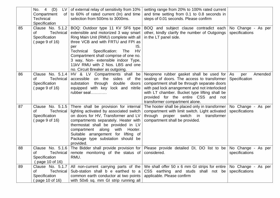
No. 4 (D) LV Compartment of Technical Specification
of external relay of sensitivity from 10% to 60% of rated current (In) and time selection from 500ms to 3000ms.
setting range from 20% to 100% rated current and time setting from 0.1 to 0.8 seconds in steps of 0.01 seconds. Please confirm
85 Clause No. 5.1.2 of Technical Specification ( page 9 of 16)
BOQ: Outdoor type 11 KV SF6 type extensible and motorized 3 way smart Ring Main Unit (RMU) complete with all three VCB and with FRTU and FPI as per IS. Technical Specification: The HV Compartment shall comprise of one no. 3 way, Non- extensible indoor Type, 11kV RMU with 2 Nos. LBS and one no. Circuit Breaker as outgoing.
BOQ and subject clause contradict each other, kindly clarify the number of Outgoings in the LT panel side.
No Change - As per specifications
86 Clause No. 5.1.4 of Technical Specification ( page 9 of 16)
HV & LV Compartments shall be accessible on the sides of the substation through double doors equipped with key lock and nitrile rubber seal…………
Neoprene rubber gasket shall be used for sealing of doors. The access to transformer compartment shall be through separate doors with pad lock arrangement and not interlocked with LT chamber. Bucket type lifting shall be provided for the entire CSS and not transformer compartment alone.
As per Amended Specification
87 Clause No. 5.1.5 of Technical Specification ( page 9 of 16)
There shall be provision for internal lighting activated by associated switch on doors for HV, Transformer and LV compartments separately. Heater with thermostat shall be provided in LV compartment along with Hooter. Suitable arrangement for lifting of Package type substation should be provided.
The hooter shall be placed only in transformer compartment with limit switch. Light activated through proper switch in transformer compartment shall be provided.
No Change - As per specifications
88 Clause No. 5.1.6 of Technical Specification ( page 10 of 16)
The Bidder shall provide provision for remote monitoring of the status of RMU.
Please provide detailed DI, DO list to be considered.
No Change - As per specifications
89 Clause No. 5.1.7 of Technical Specification ( page 10 of 16)
All non-current carrying parts of the Sub-station shall b e earthed to a common earth conductor at two points with 50x6 sq. mm GI strip running all
We shall offer 50 x 6 mm GI strips for entire CSS earthing and studs shall not be applicable. Please confirm
No Change - As per specifications

long the periphery of the Package sub-station………... The Diameter of the stud shall be at least 12mm and shall be able to connect and terminate the external earth conductor.
90 Clause No. 5.1.10 of Technical Specification ( page 10 of 16)
The galvanizing shall be carried out by the hot dip process in accordance with IS 2629/ISO 1460 amended to date. However, high tensile steel nuts, bolts &spring washer shall be electro-galvanized to service condition four. The Zinc coating shall be smooth, continuous and uniform. It shall be free from acid spots and shall not scale, blister or removable by handling or packing. there shall be no impurity in the zinc or additive to galvanic bath, which could have a detrimental effect on the durability of the zinc coating
Galvanizing process shall be applicable for HRCA base frame only, so storing and further treatment shall not be applicable. Please confirm
No Change - As per specifications
91 Clause No. 5.2.3 of Technical Specification ( page 10 of 16)
The framework shall be covered with from the front with GI sheet of thickness not less than 2mm.
LT panel shall be made of 1.5/2 mm thick CRCA sheet. Please confirm
No Change - As per specifications
Firm - 6
Sl. No. Clause No. Stipulation as per Technical Specification
Clarification / Confirmation DHBVN Comment
CSS
1 Closing time of breaker (max)
3 cycle NA since offered breaker is not for auto reclosing duty
As per specs
2 Min. Gas Pressure 0.05 BarG IEC specifies “The standard values of rated pressure are applicable unless otherwise specified by the manufacturer.” SF6 gas pressure for any GIS depends on a wide range of parameters some of which are rating
As per Amended Specification

of the product , design/rating of switching devices, design of enclosure (sealed pressure/controlled pressure), arrangement of various internal busbar connection, leakage rate envisaged for the enclosure, principle of arc quenching etc. Offered SEIL Make FBX RMU shall have minimum gas pressure of 0.2 barG.
3 Max Permissible temperture
Max Permissible temperature of the busbar& terminal shall be 45 Deg& 65 Deg C respectively at an ambient not exceeding 40 Deg C
Maximum permissible temperature for bus bar shall be 65 Deg C at an ambient temperature not exceeding 40 Deg C.
As per Amended Specification
4 Internal Arc test 20kA for 3 sec IAC-AF as per IEC 62271-200 As per Amended Specification
5 Paint Dark Gray as per RAL 7032 RAL 7032 No Change - As per specifications
6 Doors Hinged doors shall be provided. The hinges for the doors need to be riveted and shall not have any access from outdide.Bolted Hinges shall not be Acceptable.
SEIL make FBX is offered with removable type cable doors with better flexibility and space availability required for cable termination in comparison to hinged doors.Hence request you to please accept the same.
No Change - As per specifications
7 Earthing of main CCT Earthing of main CCT Cables sallbe earthed with earth switch with S/C making capacity as per IEC 129. Moving contacts of earthing switch shall be visible in closed position via transparent covers.
earthing switch position can be viewed from the front of mimic
As per Amended Specification
8 Testing of cable without opening the doors. If doors are opened then earth switch shall be in closed position and cable test rod shall be provided which can be fixed on terminations for
To be confirmed if separate test bushing are provided,it shall be covered with suitable antitheft covers with anti vandal screws
Testing of cable is possible after opening the doors but without disconnecting the cables and with all necessary interlocks in place as per IEC.
No Change - As per specifications
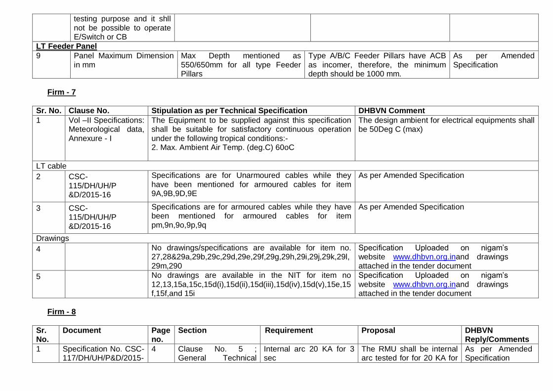
testing purpose and it shll not be possible to operate E/Switch or CB
LT Feeder Panel
9 Panel Maximum Dimension in mm
Max Depth mentioned as 550/650mm for all type Feeder Pillars
Type A/B/C Feeder Pillars have ACB as incomer, therefore, the minimum depth should be 1000 mm.
As per Amended Specification
Firm - 7
Sr. No. Clause No. Stipulation as per Technical Specification DHBVN Comment
1 Vol –II Specifications: Meteorological data, Annexure - I
The Equipment to be supplied against this specification shall be suitable for satisfactory continuous operation under the following tropical conditions:- 2. Max. Ambient Air Temp. (deg.C) 60oC
The design ambient for electrical equipments shall be 50Deg C (max)
LT cable
2 CSC-115/DH/UH/P&D/2015-16
Specifications are for Unarmoured cables while they have been mentioned for armoured cables for item 9A,9B,9D,9E
As per Amended Specification
3 CSC-115/DH/UH/P&D/2015-16
Specifications are for armoured cables while they have been mentioned for armoured cables for item pm,9n,9o,9p,9q
As per Amended Specification
Drawings
4 No drawings/specifications are available for item no. 27,28&29a,29b,29c,29d,29e,29f,29g,29h,29i,29j,29k,29l,29m,290
Specification Uploaded on nigam’s website www.dhbvn.org.inand drawings attached in the tender document
5 No drawings are available in the NIT for item no 12,13,15a,15c,15d(i),15d(ii),15d(iii),15d(iv),15d(v),15e,15f,15f,and 15i
Specification Uploaded on nigam’s website www.dhbvn.org.inand drawings attached in the tender document
Firm - 8
Sr. No.
Document Page no.
Section R Requirement Proposal DHBVN Reply/Comments
1 Specification No. CSC-117/DH/UH/P&D/2015-
4 Clause No. 5 ; General Technical
Internal arc 20 KA for 3 sec
The RMU shall be internal arc tested for for 20 KA for
As per Amended Specification

2016 Technical specification for 11 KV RING MAIN UNITS ( RMU) with inbuilt FPI & FRTU
requirements Sub point : 6
1 sec.
2 Specification No. CSC-117/DH/UH/P&D/2015-2016 Technical specification for 11 KV RING MAIN UNITS ( RMU) with inbuilt FPI & FRTU
5 Clause No. 6 ; General contruction
1 number Fault passage indicator per RMU
As per the specification with the refered clause number it is asked one number FPI per RMU. As the breaker itself has the self powered relay for operation of the breaker thus we recommend to have the FPI in the LOAD BREAK SWITCH which is formingthe ring network ( i.e one number FPI in one LBS function which is making the ring formation)
FPI to be installed on LBS only.
3 Specification No. CSC-117/DH/UH/P&D/2015-2016 Technical specification for 11 KV RING MAIN UNITS ( RMU) with inbuilt FPI & FRTU
10 Clause No. 6.4 ; CIRCUIT BREAKER ( page 10 of 24)
The CT setting shall be adjustable between 600 to 300/ 5 A
Being compact in size the cable chamber of the RMU is also compact and thus the CT secondary current shall be 1 A. Also the self powered relay using for operation of the breaker shall have the input current rating of 1 A Kindly accpet the same
As per Amended Specification
5 Specification No. CSC-117/DH/UH/P&D/2015-2016 Technical specification for 11 KV RING MAIN UNITS ( RMU) with
11 Clause No. 6.4 ; CIRCUIT BREAKER ( page 11 of 24)
4 NO + 4 NC auxiliary contacts for breaker 2 NO + 2 NC auxiliary contacts for Disconnector 1 NO + 1 NC contact for earth switch
For Breaker the direct Auxilary contacts shall be 1 NO + 2 NC. The additional auxiliary contacts shall be available using contact multiplication.
As per Amended Specification

inbuilt FPI & FRTU
6 Specification No. CSC-117/DH/UH/P&D/2015-2016 Technical specification for 11 KV RING MAIN UNITS ( RMU) with inbuilt FPI & FRTU
11 Clause No. 6.4 ; CIRCUIT BREAKER ( page 11 of 24)
The protection CT shall be epoxy resin cast with Burden 5 VA for feeder and 2.5 VA for Transformer and accuracy class of 5P10
The VA burden for protection class CT shall depends on the Reley connected to it. Thus the VA burden of 2.5 VA is sufficient enough for cater the load of the relays. Thus we shall be providing the CT having the VA burden of 2.5 VA Kindly accept the same.
As per Amended Specification
7 Specification No. CSC-117/DH/UH/P&D/2015-2016 Technical specification for 11 KV RING MAIN UNITS ( RMU) with inbuilt FPI & FRTU
12 Clause No. 6.6 ; Current Transformer and potential transformers page 12 of 24)
Appropiate capacity Cts& PTs shall be provided in the RMU for the metering purpose with the provision to provide the inputs to the FRTU for the remote SCADA/DMS/OMS functionality. The meters shall not be in the scope of supplier but the provision and space for installation of the same in future shall be available in the separate enclosure for housing the battery/ charger etc.
Pl clarify the following : 1)whether line metering is required or bus metering. 2) Whether this metering will be for tariff purpose 3) Details of CTs/PTs shall be required.
As per technical Specification. The meter is not to be provided.
8 Specification No. CSC-117/DH/UH/P&D/2015-2016 Technical specification for 11 KV RING MAIN UNITS ( RMU) with inbuilt FPI & FRTU
12 Clause No. 6.7 ; Protection relays ( page 12 of 24)
For 11 KV outgoing breakers voltage and energy readings will also be required using the MODBUS protocol from meter if applicable.
Pl clarify if the clause is applicable or not.
No Change - As per specifications
9 Specification No. CSC- 14 Clause No. 6.12 ; Shall have atleast 16 There shall be 7 setting for As per Amended

117/DH/UH/P&D/2015-2016Technical specification for 11 KV RING MAIN UNITS ( RMU) with inbuilt FPI & FRTU
Fault passage indicator ( page 14 of 24)
settings for earth fault & 4 setting for phase -phase ]
earth fault & 8 setting for phase to phase.Kindly accpet the same.
Specification
10 18 Clause No. 16; Spares, accessories & special tools / Gauges ( page 18 of 24)
Auto changeover in built requirement utilization VPI or through separate core of PT proposed on each breaker along with associated circuitry.
Please clarify this requirement.
As per Amended Specification
11 Specification No. CSC-117/DH/UH/P&D/2015-2016 Technical specification for 11 KV RING MAIN UNITS ( RMU) with inbuilt FPI & FRTU
22 Guaranteed Technical perticularss for RMU Point number : 20
Temperature rie above ambient : 50 Deg C
The temperature rise above ambient shall be as per the table 3 of the IEC 694
As per Amended Specification
12 Specification No. CSC-117/DH/UH/P&D/2015-2016 Technical specification for 11 KV RING MAIN UNITS ( RMU) with inbuilt FPI & FRTU
22 Guaranteed Technical perticularss for RMU Point number : 25
The RMU metal parts shall be greater than 3 mm thickness high tensile steel.
The SF6 gas tank shall have the steel sheet thickness of 2 mm .
As per Amended Specification
13 Specification No. CSC-117/DH/UH/P&D/2015-2016 Technical specification for 11 KV RING MAIN UNITS ( RMU) with inbuilt FPI & FRTU
23 Guaranteed Technical perticularss for RMU Point number : 40
Door : Hinged Doors shall be provided
The Doors shall be bolted type. This is the standard feature for the ****firm make RMU. Kindly accpet the same.
No Change - As per specifications
Compact Sub-Station
Sr Document Page Section Requirement Proposal DHBVN

No. no. Reply/Comments
14 Specification No. CSC-129/DH/UH/P&D/2015-2016Technical Specification for 400 KVA, 500 KVA, 630 KVA, 1000 KVA, 11/0.4 KV Compact substation
2 Clause Number : 4; General Technical perticulars ( page 2 of 16)
Max permissible temp for any accessible part of the enclosure : Max permissible temperature rise for the BUSBAR and terminals shall be 45 Deg C & 65 deg C respectively at ambient not exceeding 40 Deg C
The Max temperature rise for different part of the PSS shall be as per the relevent IEC.
No Change - As per specifications
15 Specification No. CSC-129/DH/UH/P&D/2015-2016Technical Specification for 400 KVA, 500 KVA, 630 KVA, 1000 KVA, 11/0.4 KV Compact substation
3 Clause Number : 4; General Technical perticulars ( page 3 of 16)
Paint: PENTON E2727C The paint shade for the PSS shall be RAL 1001 or RAL 7032
No Change - As per specifications
16 Specification No. CSC-129/DH/UH/P&D/2015-2016Technical Specification for 400 KVA, 500 KVA, 630 KVA, 1000 KVA, 11/0.4 KV Compact substation
4 Clause Number : 4; General Technical perticulars ( page 4 of 16)
B. RMU ; Temperature rise above ambient 50 Deg C
The temperature rise of different part of the RMU shall be as per the table 3 of IEC 694. Kindly accept the same in accordance to the IEC.
As per Amended Specification
17 Specification No. CSC-129/DH/UH/P&D/2015-2016Technical Specification for 400 KVA, 500 KVA, 630 KVA, 1000 KVA, 11/0.4 KV Compact substation
4 Clause Number : 4; General Technical perticulars( page 4 of 16)
B. RMU; point number 25 ; Degree of protection : IP 54 for outdoor application. The RMU metal parts shall be greater than 3 mm thickness high tensile steel.
For PSS application the RMU shall be placed inside a PSS enclosure having the DOP of IP 54. Thus the RMU itself shall be for indoor application.Thus separate outdoor enclosure of IP 54 for RMU is not required.The stainless steel tank having the SF6 gas
No Change - As per specifications
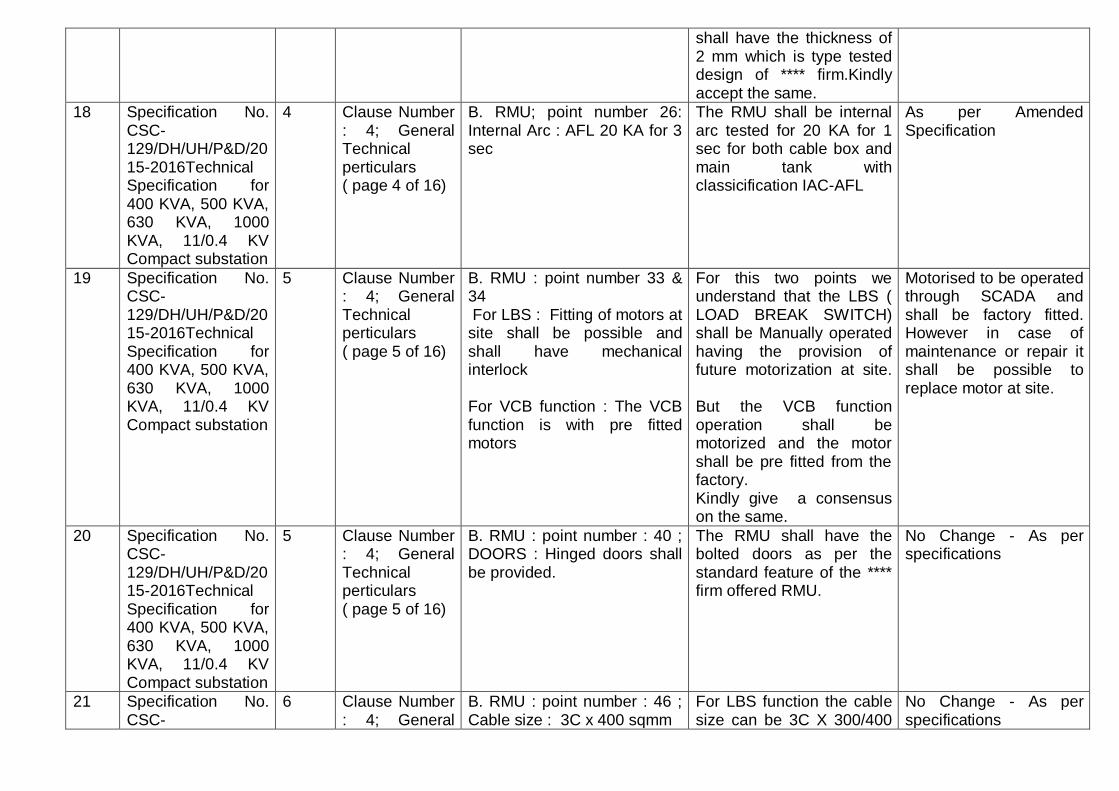
shall have the thickness of 2 mm which is type tested design of **** firm.Kindly accept the same.
18 Specification No. CSC-129/DH/UH/P&D/2015-2016Technical Specification for 400 KVA, 500 KVA, 630 KVA, 1000 KVA, 11/0.4 KV Compact substation
4 Clause Number : 4; General Technical perticulars ( page 4 of 16)
B. RMU; point number 26: Internal Arc : AFL 20 KA for 3 sec
The RMU shall be internal arc tested for 20 KA for 1 sec for both cable box and main tank with classicification IAC-AFL
As per Amended Specification
19 Specification No. CSC-129/DH/UH/P&D/2015-2016Technical Specification for 400 KVA, 500 KVA, 630 KVA, 1000 KVA, 11/0.4 KV Compact substation
5 Clause Number : 4; General Technical perticulars ( page 5 of 16)
B. RMU : point number 33 & 34 For LBS : Fitting of motors at site shall be possible and shall have mechanical interlock For VCB function : The VCB function is with pre fitted motors
For this two points we understand that the LBS ( LOAD BREAK SWITCH) shall be Manually operated having the provision of future motorization at site. But the VCB function operation shall be motorized and the motor shall be pre fitted from the factory. Kindly give a consensus on the same.
Motorised to be operated through SCADA and shall be factory fitted. However in case of maintenance or repair it shall be possible to replace motor at site.
20 Specification No. CSC-129/DH/UH/P&D/2015-2016Technical Specification for 400 KVA, 500 KVA, 630 KVA, 1000 KVA, 11/0.4 KV Compact substation
5 Clause Number : 4; General Technical perticulars ( page 5 of 16)
B. RMU : point number : 40 ; DOORS : Hinged doors shall be provided.
The RMU shall have the bolted doors as per the standard feature of the **** firm offered RMU.
No Change - As per specifications
21 Specification No. CSC-
6 Clause Number : 4; General
B. RMU : point number : 46 ; Cable size : 3C x 400 sqmm
For LBS function the cable size can be 3C X 300/400
No Change - As per specifications

129/DH/UH/P&D/2015-2016Technical Specification for 400 KVA, 500 KVA, 630 KVA, 1000 KVA, 11/0.4 KV Compact substation
Technical perticulars ( page 5 of 16)
sqmm. The cable termination from VCB function to the Transformer shall be in the scope of PSS manufacturer thus it shall be as per the manufacturer standard. The standard practice shall be 1R X 3 number 95 sqmm XLPE AL cable.
22 Specification No. CSC-129/DH/UH/P&D/2015-2016Technical Specification for 400 KVA, 500 KVA, 630 KVA, 1000 KVA, 11/0.4 KV Compact substation
6 Clause Number : 4; General Technical perticulars ( page 6 of 16)
C. TRANSFORMER ; permissible temperature rise over ambient i) of top oil measured by thermometer : 35 Deg C ii ) Of winding measured by resistance : 40 Deg C
For OIL type Trsnformer the Insulation class is A for this the oil temperature rise Is 40 deg C For the Winding temperature rise is 50 deg C.
No Change - As per specifications
23 Specification No. CSC-129/DH/UH/P&D/2015-2016Technical Specification for 400 KVA, 500 KVA, 630 KVA, 1000 KVA, 11/0.4 KV Compact substation
7 Clause Number : 4; General Technical perticulars ( page 7 of 16)
C. TRANSFORMER: point number 19 ; Maximum Flux density : 1.6 tesla
The max Flux density of the Transformer shall be 1.9 tesla. This is the standard practice for the Transformer manufacturer.
As Per Amended Specification
24 Specification No. CSC-129/DH/UH/P&D/2015-2016Technical Specification for 400 KVA, 500 KVA, 630 KVA, 1000 KVA, 11/0.4 KV Compact substation
7 Clause Number : 4; General Technical perticulars ( page 7 of 16)
C . TRANSFORMER : Point number 20 : impulse withstand 95 KVp
As the altityde height is below 1000M , thus the impluse withstand shall be 75 KVp.
No Change - As per specifications

25 Specification No. CSC-129/DH/UH/P&D/2015-2016Technical Specification for 400 KVA, 500 KVA, 630 KVA, 1000 KVA, 11/0.4 KV Compact substation
9 Clause Number : 5.1.1; OUTDOOR ENCLOSURE ( page 9of 16)
the enclosure shall be made of 2 mm thick MS sheet steel.
The outdoor enclosure shall be 2 mm thick GI.
No Change - As per specifications
26 Specification No. CSC-129/DH/UH/P&D/2015-2016Technical Specification for 400 KVA, 500 KVA, 630 KVA, 1000 KVA, 11/0.4 KV Compact substation
10 Clause Number : 5.1.6; OUTDOOR ENCLOSURE ( page 10 of 16)
The bidder shall provide provision for remote monitoring of the status of RMU.
Please provide the I/O list for remote interface.
No Change - As per specifications
27 Specification No. CSC-129/DH/UH/P&D/2015-2016Technical Specification for 400 KVA, 500 KVA, 630 KVA, 1000 KVA, 11/0.4 KV Compact substation
10 Clause Number : 5.1.7; Earthing ( page 10 of 16)
earthing of 50X 6 sqmm GI strip running all long the periphery of the package substation.
The earthing of the PSS enclosure shall be 50 x 3 sqmm AL strip which is also tested accordingly. Kindly accpet the same.
No Change - As per specifications
28 Specification No. CSC-129/DH/UH/P&D/2015-2016Technical Specification for 400 KVA, 500 KVA, 630 KVA, 1000 KVA, 11/0.4 KV Compact substation
10 Clause Number : 5.1.8; PAINT ( page 10 of 16)
the enclosure of the substation shall be painted with shade DHBVN blue
The PSS enclosre shall be powder coated RAL 7032.
No Change - As per specifications
29 Specification No. CSC-
BOQ MCCB's as outgoing along with separate DT meter
Please clarify the purpose of DT metering and provide
No change. The specification of DT meter

129/DH/UH/P&D/2015-2016Technical Specification for 400 KVA, 500 KVA, 630 KVA, 1000 KVA, 11/0.4 KV Compact substation
compartment the specifications for the same.
are available on nigam’s website www.dhbvn.org.in
Outdoor Feeder Panels with Switchgear and Metering
30 Specification No. CSC-133/DH/UH/P&D/2015-2016
5 Panel-5.13 Temperature rise of 45 deg over ambient of 40 deg
Since 50 deg is specified in clause 3.6, which is ideal as outdoor application, we recommend to have 50 deg over 45 deg and final temp 90 deg.
As Per Amended Specification
31 Specification No. CSC-133/DH/UH/P&D/2015-2016
8 Panel- 6.22 Busbar size with 10 mm thickness for Type A
As panels are tested assemblies as per IEC , hence respective OEM tested design shall be allowed to use 6 / 10 mm thickness. Based on ratings and temp rise requirements we use both 6/10mm busbar thickness
As Per Amended Specification
32 Specification No. CSC-133/DH/UH/P&D/2015-2016
8 Panel- 6.27 Max. Temperature of 80 deg at terminals
Temperature will be defined as per IEC60947-2 standards applicable for Circuit Breakers. Depending upon the contact material composition the max limt is 70 degree rsie at ACB terminal, hence total temp shall be 105 degree celcius( Ambient 35 Degree + 70 Degree rise) as per IEC . Hence it shall be changed to 105 degree only.
As Per Amended Specification
33 Specification No. CSC-133/DH/UH/P&D/2015-2016
8 Panel- 6.28 Busbar supports - StrippexStanvac
As panels required are tested assemblies as per IEC , hence respective OEM tested design busbar supports shall be allowed to use. In our case we use our Patented design with Glow-wire test
No Change - As per specifications
34 Specification 14 ACB- 7.1.6 Option of As per tender specification and As Per Amended
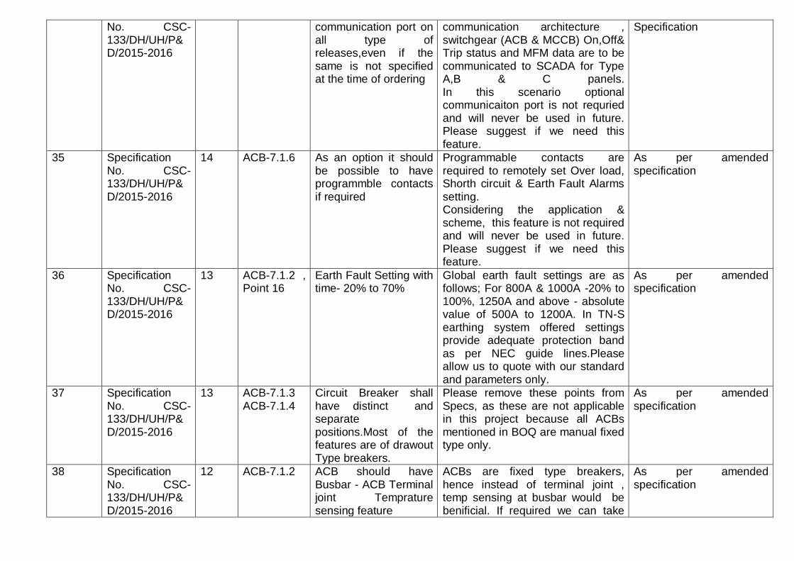
No. CSC-133/DH/UH/P&D/2015-2016
communication port on all type of releases,even if the same is not specified at the time of ordering
communication architecture , switchgear (ACB & MCCB) On,Off& Trip status and MFM data are to be communicated to SCADA for Type A,B & C panels. In this scenario optional communicaiton port is not requried and will never be used in future. Please suggest if we need this feature.
Specification
35 Specification No. CSC-133/DH/UH/P&D/2015-2016
14 ACB-7.1.6 As an option it should be possible to have programmble contacts if required
Programmable contacts are required to remotely set Over load, Shorth circuit & Earth Fault Alarms setting. Considering the application & scheme, this feature is not required and will never be used in future. Please suggest if we need this feature.
As per amended specification
36 Specification No. CSC-133/DH/UH/P&D/2015-2016
13 ACB-7.1.2 , Point 16
Earth Fault Setting with time- 20% to 70%
Global earth fault settings are as follows; For 800A & 1000A -20% to 100%, 1250A and above - absolute value of 500A to 1200A. In TN-S earthing system offered settings provide adequate protection band as per NEC guide lines.Please allow us to quote with our standard and parameters only.
As per amended specification
37 Specification No. CSC-133/DH/UH/P&D/2015-2016
13 ACB-7.1.3 ACB-7.1.4
Circuit Breaker shall have distinct and separate positions.Most of the features are of drawout Type breakers.
Please remove these points from Specs, as these are not applicable in this project because all ACBs mentioned in BOQ are manual fixed type only.
As per amended specification
38 Specification No. CSC-133/DH/UH/P&D/2015-2016
12 ACB-7.1.2 ACB should have Busbar - ACB Terminal joint Temprature sensing feature
ACBs are fixed type breakers, hence instead of terminal joint , temp sensing at busbar would be benificial. If required we can take
As per amended specification

bus bar temp parameter to SCADA via existing communication architecture.Please suggest if we need this functionality.
39 Specification No. CSC-133/DH/UH/P&D/2015-2016
16 MCCB-7.2.3 For optimum selection of ratings and breaking capacities,range of MCCBs should have established cascading charts to enhance capacity of downstream breakers. MCCB characterics shall alllow high cascading performance with MCCBs/MCBs downstream.
Cascading concept's sole objective is to use lower breaking capacity at downstream breaker than prospective short circuit current and reduce the cost of the installation. In present application breaking capacities for MCCB rating ; 400A - 50KA ; 100A-35KA are already freezed hence feature is not applicalbe in present application.
As per amended specification
40 Specification No. CSC-133/DH/UH/P&D/2015-2016
15 MCCB-7.2.2 , Point 14
As per Tender Earth fault feature is required at 400A breakers.
Please clarify whether Earth fault feature is required at only 400A MCCB at incomer level in Type-D Panels, or with all MCCBs of 400A in incoming and ourgoing feeders in respective type A,B,C feeders.
As per amended specification
Firm - 9
Sr. No.
Clause No.
Technical Description Deviation / Clarification
Clarification / Deviation DHBVN Reply/Comments
RMU
1 5 (6) Internal Arc test: 20 kA for 3 Sec Deviation As per IEC62271-200, standard time duration of internal arc test are 0.1sec, 0.5sec & 1 sec. Offered RMU shall be suitable for Internal arc withstand of 21kA for 1 sec. for tank as well as cable
As Per Amended Specification

compartment.
2 5 (12) & GTP (15.0)
Number of operations at rated short circuit current on CB : 25 nos for 11 kV VCB.
Deviation Number of operation at rated short circuit current shall be 20. However no. of operation are more at lesser fault level will be more.
No Change - As per specifications
3 5 (16) Rated cable charging interrupting current of incomer-- Load Break Switch: 10A
Deviation Rated cable charging current shall be 68A as per manufacturer's standard type tested design.
No Change - As per specifications
4 5 (17) & GTP (14.0)
Rated cable charging breaking current of breaker: 25A
Deviation Rated cable charging current shall be 68A as per manufacturer's standard type tested design.
No Change - As per specifications
5 5 (20) Temperature Rise:Maximum permissible temperature for bus bar shall be 90 deg C at an ambient temperature not exceeding 40 deg C, as per I EC 60694 And lEC 62271. However, the temperature rise for accessible enclosures and covers shall not exceed 30K and in case, they are not required to be touched during normal operation, the limit shall be raised by 10K.
Deviation As per IEC 62271-1, maximum permissible temperature for busbar shall be 115 deg C at an ambient temperature not exceeding 40 deg C.
As Per Amended Specification
6 6.1 1 way extension type Clarification In Ring Main Unit, it is not possible to offer single load break switch with incoming as well as outgoing cable termination
As Per Amended Specification
7 6.1 3 way extension type (3 VCB) Clarification FPI is not requried in VCB feeders for connecting incoming and outgoing main loop. In case of cable fault, VCB shall trip.
As Per Amended Specification
8 6.1 In addition to the above, the present specifications shall be applicable for the RMUs in case 2 run of 11 kV XLPE cable of size upto 3CX400 mm2 or 1 run of 3 nos 1CX630 mm2 are specified in the tender BOQ. The necessary modification and supply of
Clarification Customer to specify the requirement before manufacturing clearance of the RMU
As Per Amended Specification

additional items shall be in the scope of the supplier
9 6.12 The unit shall have Short Circuit and Earth fault adjustable to different settings with separate Current transformer. They shall be fully field-programmable and shall have atleast 16 settings for Earth Fault + 4 settings for phase-phase (o/c setting 200-1000 A and E/F setting 10-150 A)
Deviation Phase Fault Load current range should be settable in 7 steps from 200A upto 800 /1200A. Earth Fault Load current range should be settable in 7 steps from 10A to 100A or from 40 -300A.
As Per Amended Specification
10 6.12 IEC 60068-2-9 Environmental testing - For Vibration, solar radiations
Deviation The Fault Passage Indicators shall be suitable for use in the tropical climate condition stipulated in the relevant paragraph. The components used in the Fault Passage Indicators shall be suitably protected from direct sunlight to prevent malfunctioning due to solar radiation. The maximum operating temperature shall not be less than 70° C. The Fault Passage Indicator sensors shall be IP67 Complaint. Tests are according to standards IEC 60255-21-1, IEC 60255-21-2, IEC 60068-2-6, IEC 60068-2-27. Performed tests Vibration Response, Class 1. Vibration Endurance, Class 1. Shock Response, Class 1 . Shock Withstand, Class 1. Bump, Class 1.
No Change - As per specifications
11 6.2.1 The outer enclosure shall be made of minimum CRCA of 2 mm of GI high tensile steel 2 mm thick with thick glands plates of 3 mm.
Clarification The outer enclosure shall be made of minimum CRCA of 2 mm with thick glands plates of 3 mm.
As Per Amended Specification
12 6.2.5 Circuit breaker shall not be closed in case Earth Switch is closed.
Clarification For VCB feeder, earthing shall be done in conjuction with VCB
No Change - As per specifications

13 6.2.7 Bidder shall provide type test report to prove compliance to the 'Internal fault IAC- A as per IEC 62271-200.
Clarification Bidder shall provide type test report to prove compliance to the 'Internal fault IAC- A as per IEC 62271-200 for tank as well as cable compartment.
As Per Amended Specification
14 6.4 position of the power and earthing contacts shall be clearly visible on the front of the RMU
Clarification Since VCB & Three Position Switch is housed inside gas tank, it shall be not possible to view the position of contacts. However indication shall be provided through mimic.
As Per Amended Specification
15 6.4 Mechanical indication of the open, closed and earthed positions of the circuit breaker shall be provided.
Clarification Circuit breaker shall have only Open & Closed position. Circuit breaker feeder shall be provided with three positondisconnector for earthing of the feeder.
No Change - As per specifications
16 6.4 fast-on" test receptacle for protection testing (with or without CB tripping)
Clarification Kindly clarify As per specifications
17 6.4 The CT settings shall be adjustable between 600 to 300/5 Amp
Deviation The secondary current of CT shall be 1A As Per Amended Specification.
18 6.4 The breaker shall have the provision of flag Relay for indication of Trip on Fault High set (DT)
Clarification The breaker shall have the provision of LED indication on relay instead of flag
As per specifications
19 6.4 4. Ring core current transformers for protection depending upon the transformer ratings 2.5 VA, 5P20 for protection
Deviation Considering the compact size of RMU, we shall be providing CT with accuracy class of 5P10
As Per Amended Specification
20 6.4 9. Local remote control switch for each load break switch
Clarification It should be circuit breaker As Per Amended Specification
21 6.4 11. ON, OFF, TRIP indication on the front mimic of the panel
Clarification Only ON & OFF indication are possible on the front mimic. Trip indication shall be provided on relay indication by LED
As Per Amended Specification
22 6.6 The protection CTs shall be Epoxy resin cast with burden 5 VA for feeder and 2.5 VA for transformer and Accuracy class 5P10.
Clarification CT burden shall be 2.5VA which is sufficient for relay
No Change - As per specifications
23 6.9 The size of earth bus bar of Gl Strip (75X12 sq.mm) shall be as per lEC/IS.
Deviation RMU shall be provided with Copper earth busbar of size 30x3mm2 as per our type tested design.
As Per Amended Specification

24 6.14 There shall be provision for installation of FRTU, CT/ PT, energy meter in future, with communication capability, if needed, in the enclosure
Clarification Understand that CT / PT are requried. Space for energy meter is to be provided. Kindly confirm.
All the items except energy meter are to be provided. Only space for energy meter is required.
25 9.1 The type test produced by supplier shall be only from reputed NABL accredited testing laboratories such as CPRI from India and KEMA, Volta, KERI, CESI etc from remaining part of the globe. Report from any other testing lab mentioned above shall not be accepted. In such a case manufacture has to perform the repeat type test for the RMU form these labs at his own cost.
Clarification Request you to accept the reports from other accceredited lab such as ERDA, PHELA etc.
As Per Amended Specification
26 19 Warranty Clarification Warranty shall be 66 months from the supply and 60 months from commissioning whichever is earlier.
No Change - As per specifications
27 GTP (26.0)
Internal Arc test: A FL 20 kA for 3 Sec Deviation As per IEC62271-200, standard time duration of internal arc test are 0.1sec, 0.5sec & 1 sec. Offered RMU shall be suitable for Internal arc withstand of 21kA for 1 sec. for tank as well as cable compartment. Also the RMU shall be mounted in open area and therefore we strongly recommended that RMU shall be tested for IAC A FLR instead of only A FL
As Per Amended Specification
28 GTP (29.0)
SF6 Tank design: Hermetically/robotically sealed unpainted stainless steel enclosure with SF6 Gas. Sealed pressure system by Laser welding so that no refilling of gas is required for 30 years. No gas work at site. Complete body shall be tamperproof to prevent access to live parts. No gaskets shall be used. No bolts shall be provided
Clarification SF6 tank of offered RMU shall be MIG welded and sealed for life.There is no gas filling required for entire lifecycle of the switchgear under normal operating condition.
No Change - As per specifications

Compact substation
Sr. No.
Clause No.
Technical Description Deviation / Clarification
Clarification / Deviation DHBVN Reply/Comments
30 4.0 (A.9)
Internal Arc test: IAC AB Deviation Offered CSS shall be tested for IAC A only. The point of arc generation is very critical and IEC specify that point of initiation shall be located at the furthest accessible point from the supply. In our tested product, arc was generated in the transformer compartment which is more stringent.
As Per Amended Specification
31 4.0 (A.10)
Maximum permissible temperature of any accessible part of enclosure: Maximum permissible temperature rise for busbar and terminals shall be 45 deg. C and 65 deg. C, at ambient not exceeding 40 deg. C
Clarification We assume that it is for LV Busbars As Per Amended Specification
32 4.0(A.15)
Paint: PENTON E2727C Deviation Paint shade shall be RAL7032 with roof with RAL5021
No Change - As per specifications
33 4.0(B.14)
Rated cable charging breaking current of breaker: 25A
Rated cable charging current shall be 68A as per manufacturer's standard type tested design.
No Change - As per specifications
34 4.0(B.15)
Number of operations at rated short circuit current on CB : 25 nos for 11 kV VCB.
Deviation Number of short circuit operation for VCB are 20.
No Change - As per specifications
35 4.0(B.26)
Internal Arc test: A FL 20 kA for 3 Sec
Deviation As per IEC62271-200, standard time duration of internal arc test are 0.1sec, 0.5sec & 1 sec. Offered RMU shall be suitable for Internal arc withstand of 21kA for 1 sec. for tank as well as cable compartment. Also the RMU shall be mounted in open area and therefore we strongly recommended that RMU shall be tested for IAC A FLR instead of only A FL
As Per Amended Specification

36 4.0(B.29)
SF6 Tank design: Hermetically/robotically sealed unpainted stainless steel enclosure with SF6 Gas. Sealed pressure system by Laser welding so that no refilling of gas is required for 30 years. No gas work at site. Complete body shall be tamperproof to prevent access to live parts. No gaskets shall be used. No bolts shall be provided
Clarification SF6 tank of offered RMU shall be MIG welded and sealed for life.There is no gas filling required for entire lifecycle of the switchgear under normal operating condition.
As Per Amended Specification
37 4.0(C.15 & 16)
Transformer losses Clarification Kindly provide the energy efficiency level to be followed for transformer losses.
No Change - As per specifications
38 4.0(C.25)
Minimum clearance for air in bushing
Clarification It shall be in line with IS. No Change - As per specifications
39 4.0(D.b.15)
Max. current density of busbar- 0.8A/mm2
Clarification The dimension of terminal connection shall be goverened by product standard. Current density shall be informed duirng detailed engineering.
No Change - As per specifications
40 5.1.9 Galvanizing Clarification As per clause 5.1.1, enclosure shall be of MS Sheet steel. Kindly clarify the reason for galvanizing
No Change - As per specifications
41 5.2.1 RMU specification Clarification RMU specifications are with motorized with FRTU, however CSS specification asked for provising for remote monitoring only. Kindly clarify what to consider.
As Per Amended Specification
42 5.2.2 Distribution Transformer specification
Clarification Specification from website are for outdoor transformer with IS2026. For this requirement, transforemr shall be enclosure mounted with latest IS1180. Therefore request you to provide the specification.
The specification are available on nigam’s website www.dhbvn.org.in
43 5.2.43.1 ACB & MCCB with busbar Clarification Kindly provide the specifications. The specification are available on nigam’s website www.dhbvn.org.in
44 Approved make of transformer Clarification Kindly provide the details As per tender document.

FRTU
45 2.2 (c) Data transmission rates - 300 to 19200 bps for Serial ports for MODBUS. and 10/100 mbps for TCP/IP Ethernet ports
Deviation For IEC101 over RS232 port support 300 to 115200 bps. For Modbus over RS485 support 9600, 14400, 19200, 38400. Comply for TCP/IP port
As Per Amended Specification
46 2.2 (j) If not specified otherwise, the SCADA/DMS system will use public domain such GPRS/CDMA etc, therefore it mandatory to guard the data/ equipment from intrusion/damage/breach of security & shall have SSL/VPN based security.
Deviation External GPRS router can be used. VPN provided by telecom service provider can be used
No Change - As per specifications
47 2.2 (p) It shall be possible to retrieve and display on a laptop PC the time-stamped events recorded at the enclosure. It shall also be possible to retrieve this information from the remote control centre
Deviation SoE information can be received in CC via IEC104. Cannot retreive data at enclosure
No Change - As per specifications
48 2.2 (q) The minimum storage capacity shall be 40000 events.
Clarification Please get clarification on the application of this huge storage in the RTU
As Per Amended Specification
49 2.3 It shall be possible to increase the number of communication ports in the FRTU by addition of cards, if required in future.
Deviation No.of communication ports are fixed and cannot be extended
As Per Amended Specification
50 2.3 Different database for each master station.
Deviation Both masters will have same database As Per Amended Specification
51 2.7.3 Local/Remote selector switch :- A manual Local/Remote selector switch shall be provided for each FRTU to disable all control outputs by breaking the power supply connection to the control output s. When in the "Local" position, the Local/Remote switch shall allow testing of all the control outputs of FRTU without
Deviation LR switch need to be considered in panel and hardwiring logic to be considered for Local/Remote operation of FRTU as mentioned
No Change - As per specifications

activating the control outputs to field devices. A status input indication shall be provided for the Local/Remote switch to allow the SCADA system to monitor the position of the switch.
52 2.18 FRTU should Support following Future Provisions:- The FRTU must be capable to support PLC programming, in order to incorporate self healing grid logic for faster restoration of supply in absence of control centre SCADA. Self healing grid requires multiple communication support from FRTU (Simultaneous communication of FRTU with SCADA along with FRTU Peer to Peer communication). Hence, FRTU must support this configuration of communication to achieve SHG feature. Demonstration of self healing grid capability must be shown during bid evaluation for qualification. Provision must be there to switch off SHG logic when not required and controlling FRTU via control center
Deviation FRTU doesn't have this feature. As Per Amended Specification
Firm – 10
Sr.No.
Clause Page No.
Specified in Specification Observations by Firm DHBVN Reply/Comments
U/G 6.5/11 kV TR-XLPE Specification
1. 7 3/16 TR-XLPE compound has proven track record
AWTT certificate from compound supplier can be provided during the time of inspection. Please provide
As Per Amended Specification

acceptance on the same.
2. 7 3/16 No tolerance on negative side on insulation
As per clause 12.3 of IS :7098-II/2011 : The smallest of measured values of thickness of insulation shall not fall below the nominal value(ti)specified in Table 4 by more than 0.1mm+0.1 ti. The same shall be applicable for all the voltage grades.
No Change - As per specifications
3. 10 4/16 Core Identification As per clause 14.1.1 of IS: 7098-II/2011 Coloured polyester strips of Red, Yellow & Blue shall be used for 3 core cables. Natural colour shall be applicable for 1 core cable.
No Change - As per specifications
4. 13 4/16 Armouring Type of Armouring shall be specifically mentioned in the BOQ for the required sizes as both flat strips/round wire is specified.
As Per Amended Specification
5. 13 5/16 Non magneticarmouring as per IS :.3975
Non magneticarmouring shall be applicable as per the mutual agreement of purchaser and manufacturer as IS : 3975 is applicable for steel armouring only
As Per Amended Specification
6. 13 5/16 No tolerance on negative side on armour
As per table-6 & as per clause 17.3 of IS : 7098-11/2011 : Nominal dimensions of armour strips/wires are applicable alongwith the tolerances as specified in IS : 3975
No Change - As per specifications
7. 14 5/16 RC binder tape over armour RC tape or any other equivalent grade of tape can be used over armouring for binding purpose.
No Change - As per specifications
8. 20(i) 6/16 Variation percentage in voltage & frequency
The permissible values of variations can be given as : Voltage±10%, Frequency ± 5% Voltage & Frequency both ± 10%
No Change - As per specifications
9. 21 (A) 6/16 For each type & size, the type test shall be got carried out independently
Type test carried out on the higher size for the voltage ratings shall be applicable for all the lower sizes.
As Per Amended Specification
10. 21 (A)(d) (iii)
6/16 Degree of cross linking Internal Test Reports shall be provided during the time of inspection.
As Per Amended Specification
11. 21 (A)(f)(viiii)
7/16 Carbon Black content (For PE Sheath)
Not applicable as Outer sheath specified is of PVC Type As Per Amended Specification
12. 21 (b) (a) & (b)
7/16 Tensile Test & Wrapping Test (For Aluminium)
These tests are not applicable as per IS : 8130, In process test reports shall be submitted at the time of inspection.
As Per Amended Specification
13. 21 (B) (j) 8/16 Test for Cross linking for This test is applicable for insulation only. Internal Test As Per Amended

extruded Semiconducting screen
Reports shall be provided during the time of inspection. Specification
14. 24 8/16 Wooden Drum as per IS : 10418
Cables shall be supplied in non returnable steel drums, generally as per our plant’s standard for easy handling and storage purpose.
As Per Amended Specification
15. 25.5 10/16 Drum selection during inspection
Rewinding of drums shall be done for 1 sample per size per lot.
No Change - As per specifications
Firm - 11
Sr.No Feature Query DHBVN Reply/Comments
RMU
1 Application Confirm that RMU is suitable for outdoor Application without canopy. As per specification
2 De Rating of the RMU performance
Confirm about continous current rating of 630 Amps(without de-rating).Rating can be maintained even for outdoor Ambient Temperatures of 50 Deg C.
As per IEC
3 Safety to operator/Public Confirm that bursting pressure RELIEF IS ON REAR SIDE,LEADING THE EXHAUST GASES AWAY FROM THE OPERATOR/General public
As Per Amended Specification
4 Internal Arc Performance
Confirm that the internal Arc test is performed without venting the gases in special cable trenches.
As Per Amended Specification
5 Operator Safety Confirm that the front cover of the cable box will not fly towards the operator in case of an explosion in the cable box.
As Per Amended Specification
6 Busbars Busbars made of 99.3% Electrolytic grade Copper. As Per Amended Specification
7 DI/DO requirement Confirm the requirement of DIGITAL INPUT/DIGITAL OUTPUT or ANALOUGE for SCADA Compatibility
As per specification
8 CT/PT Requirement Confirm on Page 12 it is mentioned that CT/PT is required however at page 14 clause 6.14 ask for only providing for above.
As per specification
9 Tank Material & Stainless Steel A RMU has a pressure release device,as it can explode under As Per

Thickness Clause 6.2.2 .
Tank 2 MM thickness
certain abnormal conditions.Therefore the tank thickness is of paramount importance.RMU must have tank thickness of minimum 3 mm.RMU technology being used in India today has primarly come from Europe where such installations are installed indoor,but in india these units are mounted outdoor with lot of public around.Hence lowering of the tank thickness is a compromise with safety of Public at large apart from the diluting the tender specifications
Amended Specification
10 RMU Tank welding Clause 6.2.2 .
Sealed pressure system by Laser Welding
RMU must be robotically MIG Welded for highest & better reliability,for enhance life cycle of product.The Pulse MIG Robotic Welding is capable to generate 1000 cycles per second for heat transfer to welding zone,thereby ensuring proper fusion of the molten metal and hence forming a welding joint suitable to sustain Gas under pressure.Laser/Manual welded RMU tanks will leak environmentally hazard SF6 and the units will fail in due course of time.This will lead to huge loss of public money and loss of power supply to the needy custmors
No Change - As per specifications
11 Rated current of LBS & VCB Clause n. 5
630 ampere at 50 degree centigrate
The continous current of the load break switch and vacuum circuit breaker should be guaranteed at highest ambeinttemerature which the RMU will be exposed to 50 degcentigrate.RMU should be rated for 630 amp without derating at 50 degambeinttemerature
As per IEC
12 BOQ Sr. No. 4,6,& 12 VCB ,Relays is provided for fault display & hence FPI is applicable only for isolator(LBS) & Not for VCB
As Per Amended Specification
13 6.4 Maximum contact resistance at minimum closing force for vaccum interrupter(VI) of circuit breaker is 25 Micro-ohms
No Change - As per specifications
14 6.4 & 6.6 Current Transformer for protection:50-100/1A,2.5VA burden,Accuracy class:5P10
As Per Amended Specification
15 6.4 Digital input for self poweredrelay:common digital indication for overcurrent &reath fault
As per specification
16 6.6 For offered RMU,Metering CT & PY;s. Enclosure for the same will be provided as indicated in the tender specifications
As per specification
17 6.14 Battery life will be as per manufacturer;s standard/warrantee As per specification
Firm -12
SI. Clause No. Description Vendor Pre-Bid Query DHBVN Reply/Comments

No. 1. 1 2. Clause No. 1
Scope (page 3 of 24
General Description Specification asked for 11kV RMU with inbuilt FPI & FRTU (of same manufacturer). “To invite the fair competition from RMU & FRTU, we request DHBVN to not to restrict the same make interlock between RMU & FRTU. Kindly allow FRTU of different makes also.”
As Per Amended Specification
2. 2 BOQ General Description of BOQ CSS vendor scope shall be strictly limited to only supply of CSS. CSS shall be delivered alongwith fully wired FRTU panel with necessary DI DO as required on Terminal Block, however FRTUs and necessary accessories for FRTU shall be supplied directly from FRTU vendor. Please provide the dimensional details of FRTU to accomodate the same inside CSS.
No Change - As per specifications
3. 3 BOQ General Description of BOQ Please clarify in detail what is meant by separate DT metering Compartment, whether only space provision in LT compartment (inside CSS ) is to be provided and what will be the dimension of the meter(technical details of the meter like class of accuracy etc), whether same has to be considered in our scope of supply.
Space provision to be made. Meter specification are available on www.dhbvn.org.in
4. 4 BOQ, Clause 5.1.2 General Description of BOQ As per rating of transformer, 630kVA and 400kVA the LT Busbar rating is given as 1600 Amps in the BOQ and 1250A and 800A are mentioned in the specification, please clarify which one to consider.
As per amended BOQ
CSS
5. 5 Technical Specification -
Minimum thickness of sheet a) Sides - 2 mm
Offered CSS shall be a type tested design according to latest IEC 62271-
No Change - As per specifications

Clause Number 4.0 point number 11 and 5.1.1
b) Base - 4 mm 202 and shall have 1.5 mm thick non load bearing members and 2 mm thick load bearing members with a base frame of 4mm.
6. 6 Technical Specification - Clause Number 4.0 point number 11
Maximum permissible temperature rise for the bus bar and terminals shall be 45 deg C & 65 deg c respectively, at ambient not exceeding 40 deg. C.
This we assume is for LT Panel inside CSS, for which all the limits of Temperature rise shall be as per IEC 61439.
No Change - As per specifications
7. 7 Technical Specification - Clause Number 4.0 point number 15
Colour shade - PENTON E2727C We offer DA Gray , Light Gray CSS with shades nearer to RAL 7035 for Enclosure and for roof it shall be nearer to IS 632.
No Change - As per specifications
8. 8 Technical Specification - Clause Number 4.0 B (RMU) point number 2
RMU Application - Containerized By Containerised RMU we understand it is indoor modular compact switchgear placed inside CSS with IP54 compartment for HT.
No Change - As per specifications
9. 1
0
Technical Specification - Clause Number 4.0 B (RMU) point number 16,17
Opening time of breaker (max.) - 2.5 Cycle Closing Time of breaker (max.) - 3 Cycle
Opening Time of breaker - (approx 40 - 80 ms) Closing Time of breaker - (approx 40 - 70 ms)
As Per Amended Specification
10. 1
1
Technical Specification - Clause Number 4.0 B (RMU) point number 19
Electrical operation of earth switch at rated current
Looking at safety aspect, Electrical Operation of Earth switch is not recommended.
As Per Amended Specification
11. 1
2
Technical Specification - Clause Number 4.0 B (RMU) point number 21
Min Gas pressure - 0.05 Bar G Ideally due to atmospheric pressure outside the tank of RMU, gas pressure cannot go below 1 bar hence suitable min gas pressure shall be provided in offered RMU.
As Per Amended Specification
12. 1
3
Technical Specification - Clause Number 4.0 B (RMU) point number 25
IP 67 for the tank and IP2X for the front cover /mimic board and IP54 for Outdoor RMUs. The RMU metal parts shall be greater than 3mm thickness high tensile steel which must be shot blasted, spray galvanized with minimum
(SF6 tank shall be made up of stainless steel SS 304 grade with thickness 2.5 mm and Enclosure made up of 2 mm thick CRCA which shall be duly powder coated followed by 7 tank process which shall have paint thickness of 60-
As Per Amended Specification

thickness of 30 micron and subsequently powder coated. The overall paint thickness shall be not less than 70 microns
80 microns)
13. 1
4
Technical Specification - Clause Number 4.0 B (RMU) point number 26
Internal Arc -AFL 20 KA for 3 sec. Internal arc for RMU shall be 21kA for 1 second however STC shall be 21kA for 3 seconds.
As Per Amended Specification
14. 1
5
Technical Specification - Clause Number 4.0 B (RMU) point number 31
As per specification ?? Offered RMU shall have Earth bus of 30 mm x 4 mm Copper material.
As Per Amended Specification
15. 1
6
Technical Specification - Clause Number 4.0 B (RMU) point number 32
Earthing of main CCT Cables shall be earthed with earth switch with. S/C making capacity as per I EC 129. Moving contacts of earthing switch shall be visible in closed position via transparent covers.
All live parts are enclosed inside robotically welded stainless steel tank hence visibility of moving contacts of earth switch shall not be applicable. Please clarify what do you mean by "Earthing of main CCT Cables shall be earthed via earth switch with Short circuit making capacity as per IEC 129"
As Per Amended Specification
16. 1
7
Technical Specification - Clause Number 4.0 B (RMU) point number 33
Fitting of motor at site shall be possible & shall have mechanical interlock.
Fitting of motor at site shall always be possible however please clarify whether manual or motorised version of LBS is needed.?
Motorized As per specification
17. 1
8
Technical Specification - Clause Number 4.0 B (RMU) point number 35
Self-powered relay with O/C IDMT characteristic with minimum PSM-0.2 JMS-0.01 +E/F IDMT characteristic with minimum PSM JMS -0.01 Hi-set setting for O/C + E/F min setting 0.5 in and delay 20 ms
We offer self powered microprocessor based (3 O/C + 1 E/F Relay) with setting range as 20% to 200% for Overcurrent and 10% to 80% for earth fault protection) . Please clarify the detail as mentioned in GTP.
As Per Amended Specification
18. 1
9
Technical Specification - Clause Number 4.0 B (RMU) point number 36
Suitable numerical relay with necessary elements or any other as per Purchaser's approval
We shall offer microprocessor based self powered relay as per vendor approved vendor list
As Per Amended Specification

19. 2
0
Technical Specification - Clause Number 4.0 B (RMU) point number 38
Testing of Cable- without opening the doors. If doors are opened then earth switch shall be in closed position and cable test rod shall be provided which can be fixed on terminations for testing purpose and it shall not be possible to operate, E/Switch or CB
Cable testing facility shall be available only after opening the cable cover however same shall be possible without dismantling the cable termination.
No Change - As per specifications
20. 2
1
Technical Specification - Clause Number 4.0 B (RMU) point number 39
Design of RMU shall be tamper & arc proof. Anti vandal screws shall be provided. Cable covers shall be pad lockable. All live parts / test bushings etc. shall be covered with antitheft covers.
As the RMU shall be inside HT compartment of IP54 degree of ingress protection,
No Change - As per specifications
21. 2
2
Technical Specification - Clause Number 4.0 B (RMU) point number 42
Phase Comparator - 1 per RMU 1 Number Phase comparator shall be provided for entire lot of CSS.
No Change - As per specifications
22. 2
3
Technical Specification - Clause Number 4.0 B (RMU) point number 51
Busbar material -Tinned Copper Offered RMU shall have busbar material of Electrolytic Copper.
As Per Amended Specification
23. 2
4
Technical Specification - Clause Number 4.0 B (RMU) point number 55
Guarantee - 72 months from the date of commissioning
Offered CSS shall have warranty 60 months from date of commissioning or 66 months from date of supply which ever is earlier.
No Change - As per specifications
24. 2
5
Technical Specification - Clause Number 4.0 B (RMU) point number 58
Colour Shade -Dark Gray as per RAL 7032
Offered RMU shall have paint shade of RAL 7035
No Change - As per specifications
25. 2
6
Technical Specification - Clause Number 4.0
Earth Switch operation counter Counter for earth switch shall not be applicable.
As Per Amended Specification

B (RMU) point number 62
26. 2
7
Technical Specification - Clause Number 4.0 C(Transformer) point number 1
Application - Container The Transformer shall be placed inside compartment of IP23 degree of ingress protection of the CSS.
As Per Amended Specification
27. 2
8
Technical Specification - Clause Number 4.0 C(Transformer) point number 5
Rated Voltage LV - 433 V-250V The Transformer shall have rating as per BOQ as 11kV/0.433kV only. 250V LV shall not be applicable.
As Per Amended Specification
28. 2
9
Technical Specification - Clause Number 4.0 C(Transformer) point number 13
Noise level at rated voltage and frequency - 57 db
The Transformer noise level shall be as per relevant IS/IEC/NEMA levels.
As Per Amended Specification
29. 3
0
Technical Specification - Clause Number 4.0 C(Transformer) point number 14
Permissible temperature rise over ambient i) Of top oil measured by thermometer - 35 degrees ii)Of winding measured by resistance - 40 degrees
As per the latest IS 1180 amendment for transformers the temperature rise to be considered for Oil/Winding is 40/45 degrees over ambient.
As Per Amended Specification
30. 3
1
Technical Specification - Clause Number 4.0 C(Transformer) point number 24
Neutral Terminal - Two separate brought out neutral from main neutral bus bar, One for taking out the neutral for 4 wire system and other additional neutral for solid earthing.
Please clarify in detail the requirement of neutral terminal.
No Change - As per specifications
31. 3
2
Technical Specification - Clause Number 4.0 C(Transformer) point number 25
Minimum clearances in air for bushing terminals a) HV phase to phase/ phase to earth (mm) - 255/140 b) LV phase to phase/ phase to earth (mm) - 75/40
Clearances shall be as per CBIP norms. No Change - As per specifications
32. 3
3
Technical Specification - Clause Number 4.0
Maximum current density of bus bar 8 Amp./sq mm
We read Current density of bus bars as 0.8 A /sq.mm
Clarify - it is 0.8A/sqmm

C(LV Compartment) point number 1
33. 3
4
Technical Specification - Clause Number 4.0 C(LV Compartment) point number 2 , 16
Maximum permissible temperature rise 80 Deg C at terminals with an ambient temperature not exceeding 40 deg C
Maximum Temperature rise limits shall be as per IEC 61439.
As per amended specification
34. 3
5
Technical Specification - Clause Number 4.0 C (a)(LT ACB) point number 19
Overloading current with time setting 40 to 100 % with function disable (off) option Time setting (tr) from – 1s,2s,4s to ... 24 sec
Time setting and disable option shall be as per manufacturer standard.
As per amended specification
35. 3
6
Technical Specification - Clause Number 4.0 C (a)(LT ACB) point number 20, 21,22
Earth Fault Setting with time 20% to 70% with function disable (off) option Time Setting – 100ms to 400ms
Time setting and disable option shall be as per manufacturer standard.
As per amended specification
36. 3
7
Technical Specification - Clause Number 4.0 C (c)(LT MCCB) point number 17
For MCCB of 400 A & 630 A -With the help of external relay of sensitivity from 10% to 60% of rated current (In) and time selection from 500ms to 3000ms
We can offer Earth fault release along with the MCCB with in built Earth fault release with setting range from 20% to 100% rated current and time setting from 0.1 to 0.8 seconds in steps of 0.01 seconds.
As per amended specification
37. 3
8
Technical Specification - Clause Number 5.1.2
The transformer shall be of 11/0.433 kV, 400,500,630 & 1000kVA, hermetically sealed with corrugated tank construction. The LV compartment shall comprise of one no. 800 A ACB with 3 nos., 400A each MCCB for 400 kVA transformer, 800 A ACB with 3 nos., 400A each MCCB for 500 kVA, one no. 1250 A ACB with 4nos., 400A each MCCB for 630kVA transformer &1600 A ACB with 5 nos. 400A each MCCB for 1000kVA other auxiliary components with interconnections required for the
BOQ and subject clause contradict each other, kindly clarify the number of Outgoings in the LT panel side.
Please refer amended BOQ

complete operation of the sub-station 38. 3
9
Technical Specification - Clause Number 5.1.4
HV and LV compartments shall be accessible on the sides of the substation through double doors equipped with key lock and nitrile rubber seal . Transformer chamber door can be opened by accessing from the door arrangement from LT compartment.Two No. lifting arrangements shall be provided on both sides of transformer chamber
Neoprene rubber gasket shall be used for sealing of doors. The access to transformer compartment shall be through separate doors with pad lock arrangement and not interlocked with LT chamber. Bucket type lifting shall be provided for the entire CSS and not transformer compartment alone.
As Per Amended Specification
39. 4
0
Technical Specification - Clause Number 5.1.5
There shall be an arrangement for internal lighting activated by associated switch on doors for HV, Transformer and LV compartments separately Heater with thermostat shall be provided in LV compartment along with Hooter
The hooter shall be placed only in transformer compartment with limit switch. Light activated through proper switch in transformer compartment shall be provided.
No Change - As per specifications
40. 4
1
Technical Specification - Clause Number 5.1.6
The Bidder shall provide provision for remote monitoring of the status of RMU, Fault passage indicator, LT ACB & MCCB’s, Transformer OTI.
Please provide detailed DI,DO list to be considered.
No Change - As per specifications
41. 4
2
Technical Specification - Clause Number 5.1.7
Four nos. earthing terminals/studs shall be provided on the enclosure at each corner positions which shall be internally connected to the common earth conductor/strip provided for the entire sub-station. The diameter of the stud shall be at least 12mm and shall be able to connect and terminate the external earth conductor
We shall offer 50 x 6 mm GI strips for entire CSS earthing and studs shall not be applicable.
No Change - As per specifications
42. 4
3
Technical Specification - Clause Number 5.1.10
The galvanizing shall be carried out by the hot dip process in accordance with IS 2629/ ISO 1460 amended to date. However, high tensile steel nuts, bolts & spring washers shall be electro-galvanized to service condition four.
Galvanising process shall be applicable for HRCA base frame only, so storing and further treatment shall not be applicable.
No Change - As per specifications

The zinc coating shall be smooth, continuous and uniform. It shall be free from acid spots and shall not scale, blister or removable by handling or packing. There shall be no impurity in the zinc or additives to galvanic bath, which could have a detrimental effect on the durability of the zinc coating 5.1.12 To avoid the formation of white rust, galvanized material shall be stacked during transport and stored in such a manner as to permit adequate ventilation. Sodium dichromate treatment shall be provided to avoid formation of white rust after hot dip galvanization. The galvanized steel shall be subject to tests as per IS 2633/ BS 729 amended to date
43. 4
4
Technical Specification - Clause Number 5.2.3
The complete arrangement of ACB and MCCBs shall be provided on a framework of channels with adequate strength to support the weight of the ACB and MCCB’s. The Framework shall be covered from the front with GI sheet of thickness not less than 2 mm
LT panel shall be made of 1.5/2 mm thick CRCA sheet.
No Change - As per specifications
44. 4
5
Technical Specification - Clause Number 5.2.1 and 5.2.2
Specifications not received We have received Specification No : CSC-129/DH/UH/P&D/2016-16, no separate Nigam specifications for RMU,Transformer and FRTU were received hence all the queries are with respect to available document only.
All specifications are available on www.dhbvn.org.in
45. 4
6
Technical Specification - Clause Number 8 to 17
8.0 PRE- DESPATCH INSPECTION 9. INSPECTION AFTER RECEIPT AT STORE 10. GUARANTEE 11. PACKING 12. TENDER SAMPLE 13. QUALITY CONTROL 14. MINIMUM TESTING FACILITIES 15. MANUFACTURING ACTIVITIES 16.
All the listed Clauses shall be discussed in the event of Order.
No Change - As per specifications

SPARES, ACCESSORIES AND TOOLS(As per Nigam Specifications) 17. DRAWING AND DOCUMENTS
11 kV Ring Main Unit (RMU) with inbuilt FPI & FRTU
46. S
r
.
N
o
.
Clause No. Pre-Bid query DHBVN Reply/comment
47. 4
7
Clause No. 4 (1.) Climatic Conditions (page 4 of 24)
Maximum ambient air temperature: 50 deg C RMU shall be designed for 630A current at 40 deg C ambient temperature as per IEC 62271-200. Current deration shall be applicable at 50 deg C.
As per IEC
48. 4
8
Clause No. 4 (2.) Climatic Conditions (page 4 of 24)
Minimum ambient air temperature: (-)5deg C For better reliability and ease of operation in extreme winter condition, RMU should be desgined for (-) 25 deg C ambient. We request DHBVN to amend the ambient temperature to (-) 25 deg C
No Change - As per specifications
49. 3 Clause No. 5 (5.) General Technical equirements (page 4 of 24)
SF6 gas at relative pressure : 0.05 bar G Filling pressure of SF6 gas shall be 0.4 bar relative at 20 deg C.
As Per Amended Specification
50. 4 Clause No. 5 (20.) General Technical equirements (page 5 of 24)
Maximum permissible temperature for bus bar shall be 90 deg C at an ambient temperature not exceeding 40 deg C as per IEC 60694 and IEC 62271. As per IEC 62271-1, clause no. 4.4.2, maximum value of temeparure of bus bar shall be 105 deg C in SF6 environment at an ambient temperature not exceeding 40 deg C. Kindly accept maximum permissible temperature for bus bar as 105 deg C instead of 90 deg C
As Per Amended Specification
51. 5 Clause No. 6.1 General Construction (page 5 of 24)
- 1 Way extension type (one side) indoor/outdoor application, 11kV RMU consist of 1 no. 630A LBS along with one incoming& one outgoing cable provision Kindly clarify whether this extension unit shall be used to couple with other RMU at site or it will be standalone RMU.
It may be an extension unit or standalone as per site/ foot survey
52. 6 Clause No. 6.1 General Construction
- 3 Way extension type (one side) indoor/outdoor application, 11kV RMU consist of 3 no. 630A VCB……… 1 No. electronic fault passage indicator
-FPI is not required in case of 3 way RMU consisting of

(page 6 of 24) per RMU & FRTU Note that RMU shall consist of 3 VCB configuration RMU wherein Fault passage indicator is not required. Fault indication shall be there in relay. We request DHBVN to remove FPI from this configuration RMUs.
3 nos VCBs.
53. 7 Clause No. 6.1 General Construction (page 6 of 24)
- 5 Way extension type (one side) indoor/outdoor application, 11kV RMU consist of 2 no. LBS & 3 no. 630A VCB. As per BOQ of RMU, 5 Way RMU shall consist of 3 LBS and 2 VCB with other accessories however specs calls for 2 LBS and 3 VCB configuration RMU. Kindly clarify the exact requirement.
As Per Amended Specification
54. 8 Clause No. 6.1 General Construction (page 6 of 24)
in case of 2 run of 11kV XLPE cable of size up o 3C x 400 Sq. mm or 1 run of 3 Nos. 1C x 630 Sq. mm are specified in BOQ. The necessary modification and supply of additional items shall be in the scope of supplier. Please note that specifications call for 1 run of 3Cx 400 Sq. mm cable. In case 2 runs of cables are required, provision for termination for same cable shall be made in cable compartment of LBS however due to installtion of protection CTs in cable compartment of VCB module, 2 runs of cable won't be suitable for VCB module.
As Per Amended Specification
55. 9 Clause No. 6.2 RMU Design Features (page 6 of 24)
The manufacturer shall depute his representative for supervision of the installation, testing & commissioning of RMUs at site. To have the clarity on scope, we request DHBVN to clearly define the mandays per RMU for providing supervision of installation, testing & commissioning of RMU at site
No Change - As per specifications
56. 1
0
Clause No. 6.2.1 Outer Enclosure features (page 7 of 24)
The outer enclosure shall be made of minimum CRCA of 2 mm of GI high tensile steel 2 mm thick with thick glands plates of 3mm Kindly clarify whether outer enclosure shall be made of minimum CRCA or GI.
As Per Amended Specification
57. 1
1
Clause No. 6.2.1 Outer Enclosure features (page 7 of 24)
The complete RMU shall eb powder coating of RAL 7032 Grey to DIN standard 43656 RMU Paint shade shall be as under: Front Cover : RAL 7035 Cable cover : RAL 7035 Outer Enclosure : IS 632 We request DHBVN not to restrict the paint shade and let it open for all manufaturer.
No Change - As per specifications
58. 1
2
Clause No. 6.2.2 Indoor Enclosure features (page 7 of 24)
The tank shall be corrosion resistance stainless steel heet of minimum 2 mm (as per relevant IS/IEC) IS/IEC do not mention about tank thickness. Tank is heart of RMU and it
As Per Amended Specification

is not recommened to accept any steel of 2 mm thick. Being application of RMUs for prestigious project and for better reliability, performance and durable life, we request DHBVN to amend the tank sheet thickness to atleast 2.5mm and tank steel should be made of non ferrite and non magnetic steel. This steel with 2.5 thickness can be provided by any RMU manufaturer.
59. 1
3
Clause No. 6.2.4 (page 8 of 24)
The RMU shall be with all connection and with tinned copper Please note that bus bar shall be made of base copper only instead of tinned copper. IEC 62271-1 do not mention about tinned copper. Parameters like temperature rise etc is defined w.r.t bare copper only. We request DHBVN to accept bare copper bus bar. Tinned copper is not required/applicable.
As Per Amended Specification
60. 1
4
Clause No. 6.4 Circuit Breakers (page 10 of 24)
The circuit breaker…………………shall include three toroid transformer incorporated in the transformer tee-off bushing. Protection and metering transformers shall be of resin cast and shall be installed in cable compartment over cable. CTs installation on bushing is not recommended since chances get increase for damage which casues gas leakage. We request DHBVN not to allow CTs installation on bushing.
As Per Amended Specification
61. 1
5
Clause No. 6.4 Circuit Breakers (page 10 of 24)
The CT steeting shall be adjustable between 600 to 300/5A CTs rating can be anything rating between 600 to 300/1A. Protection relay have setting of O/C from 20% to 200% to achieve tripping on fault. Secondary rating of CTs shall be 1A.
As Per Amended Specification
62. 1
6
Clause No. 6.6 CTs and PTs (page 11 of 24)
Appropriate capacity CTs & PTs shall be provided in the RMU for the metering purpose with the provision to provide the inputs to the FTRU for remote SCADA/DMS/OMS functionality. The meter shall not be in the scope of supplier however the provision and space for installation of the same in future shall be available in the seperate enclosure for housing the battery/charger etc. Kindly confirm the provision of metering in which module. Is meterign to be provided for VCB or LBS or both? What is the size of meter to provide space in metering panel?
As per specification Meter space to be provided only Specifications given on website
63. 1
7
Clause No. 6.9 Earthing (page 13 of 24)
The RMU outdoor metal clad RMU shall be outdoor metal enclosed type.
No Change- As per specification
64. 1
8
Clause No. 6.9 Earthing (page 13 of 24)
The size of earth bus bar of GI strip (75 x 12 sq. mm) shall be provided……. Provision shall be made on the end of RMU for connecting the earth bus to earth grid by erecting suitable 2 earth pipes of.... ..to be
As Per Amended Specification

connected in grid formation GI earthing is not recommended in RMU. We request DHBVN to amend the earth bus to Coppper of 30 x 4 Sq. for better performance, reliability and life. RMU shall have provision on end of RMU connecting the earth bus to earth grid but Pipes and M.S rod or any accessiories for connecting it to earth grid shall not be in manufacturer scope of supply
65. 1
9
Clause No. 6.13 Motors (page 14 of 24)
The max current drawn shall be 9 amp (+/- 10%) Peak current of motor shall be 14 amp
No Change- As per specification
66. 2
0
Clause No. 6.14 Power Supply, Battery & Charger (page 14 of 24)
There shall be provision of installation of FRTU, CT/PT, energy meters in future Kindly let us know the size of FRTU which provision has to made in RMU. We shall provide space provision in Metering cubicle to install FRTU at site in future.
No Change- As per specification
67. 2
1
Clause No. 6.14 Power Supply, Battery & Charger (page 14 of 24)
The auxiliary power transformer's input shall be equipped with surge protection device RMU is itself a very compact switchgear hence due to space contraints, it is not feasible to install any surge protection device in RMU. We request DHBVN to delete this clause.
No Change- As per specification
68. 2
2
Clause No. 7 Paint (page 15 of 24)
The enclosure of the RMU shall be painted with RAL 7032 Grey . RMU Paint shade shall be as under: Front Cover : RAL 7035 Cable cover : RAL 7035 Outer Enclosure : IS 632 We request DHBVN not to restrict the paint shade and let it open for all manufaturer.
No Change- As per specification
69. 2
3
Clause No. 9.4 Acceptance test (page 17 of 24)
Heat run test shall be carried out on one random sample/configurations/tender quantity as acceptance test. Temperature rise test (Heat run test) is type test which is already carried out on RMUs. Type test reports shall be furnish with bid. Same test can not be performed during acceptance test. We request DHBVN to remove this test from acceptance test.
No Change- As per specification
70. 2
4
Clause No. 9.4 Acceptance test (page 17 of 24)
In additon SCADA operations in the RMU along with FRTU should be demonstrated during factory inspection in manufacturer's own labs failing which the supplies shall not be accepted. RMU and FTRUs are two different products which are getting manufatured in different factories. Integration of FRTU in RMU shall be
No Change- As per specification

done at site by respective manufacturer. SCADA operations in the RMU along with FRTU should be demonstrated during factory inspection is not feasible. We request DHBVN to remove this test from acceptance test.
71. 2
5
Clause No. 9.4 (a) Acceptance test (page 17 of 24)
Facility for primary current injection up to 1000A Note that primary injection is done thru bushing only hence primary injection current shall be limited to rated current only i.e 630A max.
No Change- As per specification
72. 2
6
Clause No. 9.4 (a) Acceptance test (page 17 of 24)
Pre-commissioning test to be conducted on each RMU before installations and commissioning Pre-commissioning test shall not be in RMU manufacturer's scope.
No Change- As per specification
73. 2
7
Clause No. 16 Spares, Accessories & Special tools/Gauges (page 18 of 24)
Autochangeover in-built requirement utilization VPIS or through separate core of PT proposed on each breaker along with assocoatedcircutiry. This point is not clear. Kindly elabore the autochangeover scheme. Auto changeover is nowehere mentioned in specs expect this clause. Kindly confirm the scheme if it is required.
As per Amended Specification
74. 2
8
Clause No. 18 Challenge clause (page 20 of 24)
Kindly delete this clause. Material shall be dispatched onlt after successful inspection and getting dispatch clearance. Un acceptance at site after inspection and then paying penalty of 10% is not acceptable.
No Change- As per specification
75. 2
9
Clause No. 19 Warrantee Period (page 20 of 24)
72 months from the date of commissioning 1. Supplier shall repair or replace at their option, free of cost, on ex - works basis the whole or any portion of material/ equipment which under normal and proper use and maintenance proves defective in material and/ or workmanship within 60 months from the date of commissioning or 66 months from the date of shipment of equipment which¬ever is earlier, provided prompt notice is given of such defects. If there is any delay in commissioning for any reason not attributable to the supplier for more than 15 days, the supplier shall issue 07 day’s notice to the purchaser to commission the equipment. Failure to comply the notice of the supplier by the purchaser, the equipment shall be deemed to have been commissioned from the date of notice and warranty period shall commence w.e.f. date of the notice of the supplier. It is further understood that repair and/or replacement of the defective equipment shall be the sole and exclusive remedy available to the purchaser. 2. Such replacements will be effected within a reasonable time actually required to do so. 3. Supplier liability arising out of supply¬ing the material or its use,
No Change- As per specification
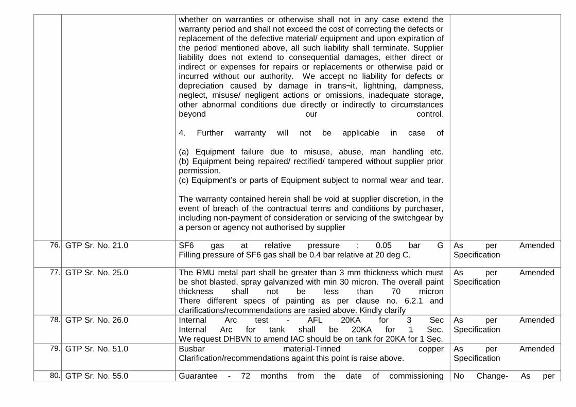
whether on warranties or otherwise shall not in any case extend the warranty period and shall not exceed the cost of correcting the defects or replacement of the defective material/ equipment and upon expiration of the period mentioned above, all such liability shall terminate. Supplier liability does not extend to consequential damages, either direct or indirect or expenses for repairs or replacements or otherwise paid or incurred without our authority. We accept no liability for defects or depreciation caused by damage in trans¬it, lightning, dampness, neglect, misuse/ negligent actions or omissions, inadequate storage, other abnormal conditions due directly or indirectly to circumstances beyond our control. 4. Further warranty will not be applicable in case of (a) Equipment failure due to misuse, abuse, man handling etc. (b) Equipment being repaired/ rectified/ tampered without supplier prior permission. (c) Equipment’s or parts of Equipment subject to normal wear and tear. The warranty contained herein shall be void at supplier discretion, in the event of breach of the contractual terms and conditions by purchaser, including non-payment of consideration or servicing of the switchgear by a person or agency not authorised by supplier
76. 3
0
GTP Sr. No. 21.0 SF6 gas at relative pressure : 0.05 bar G Filling pressure of SF6 gas shall be 0.4 bar relative at 20 deg C.
As per Amended Specification
77. 3
1
GTP Sr. No. 25.0 The RMU metal part shall be greater than 3 mm thickness which must be shot blasted, spray galvanized with min 30 micron. The overall paint thickness shall not be less than 70 micron There different specs of painting as per clause no. 6.2.1 and clarifications/recommendations are rasied above. Kindly clarify
As per Amended Specification
78. 3
2
GTP Sr. No. 26.0 Internal Arc test - AFL 20KA for 3 Sec Internal Arc for tank shall be 20KA for 1 Sec. We request DHBVN to amend IAC should be on tank for 20KA for 1 Sec.
As per Amended Specification
79. 3
3
GTP Sr. No. 51.0 Busbar material-Tinned copper Clarification/recommendations againt this point is raise above.
As per Amended Specification
80. 3GTP Sr. No. 55.0 Guarantee - 72 months from the date of commissioning No Change- As per
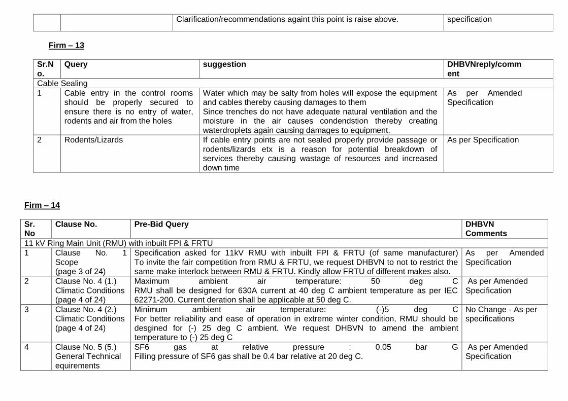
4 Clarification/recommendations againt this point is raise above. specification
Firm – 13
Sr.No.
Query suggestion DHBVNreply/comment
Cable Sealing
1 Cable entry in the control rooms should be properly secured to ensure there is no entry of water, rodents and air from the holes
Water which may be salty from holes will expose the equipment and cables thereby causing damages to them Since trenches do not have adequate natural ventilation and the moisture in the air causes condendstion thereby creating waterdroplets again causing damages to equipment.
As per Amended Specification
2 Rodents/Lizards If cable entry points are not sealed properly provide passage or rodents/lizards etx is a reason for potential breakdown of services thereby causing wastage of resources and increased down time
As per Specification
Firm – 14
Sr. No
Clause No. Pre-Bid Query DHBVN Comments
11 kV Ring Main Unit (RMU) with inbuilt FPI & FRTU
1 Clause No. 1 Scope (page 3 of 24)
Specification asked for 11kV RMU with inbuilt FPI & FRTU (of same manufacturer) To invite the fair competition from RMU & FRTU, we request DHBVN to not to restrict the same make interlock between RMU & FRTU. Kindly allow FRTU of different makes also.
As per Amended Specification
2 Clause No. 4 (1.) Climatic Conditions (page 4 of 24)
Maximum ambient air temperature: 50 deg C RMU shall be designed for 630A current at 40 deg C ambient temperature as per IEC 62271-200. Current deration shall be applicable at 50 deg C.
As per Amended Specification
3 Clause No. 4 (2.) Climatic Conditions (page 4 of 24)
Minimum ambient air temperature: (-)5 deg C For better reliability and ease of operation in extreme winter condition, RMU should be desgined for (-) 25 deg C ambient. We request DHBVN to amend the ambient temperature to (-) 25 deg C
No Change - As per specifications
4 Clause No. 5 (5.) General Technical equirements
SF6 gas at relative pressure : 0.05 bar G Filling pressure of SF6 gas shall be 0.4 bar relative at 20 deg C.
As per Amended Specification

(page 4 of 24)
5 Clause No. 5 (20.) General Technical equirements (page 5 of 24)
Maximum permissible temperature for bus bar shall be 90 deg C at an ambient temperature not exceeding 40 deg C as per IEC 60694 and IEC 62271. As per IEC 62271-1, clause no. 4.4.2, maximum value of temeparure of bus bar shall be 105 deg C in SF6 environment at an ambient temperature not exceeding 40 deg C. Kindly accept maximum permissible temperature for bus bar as 105 deg C instead of 90 deg C
As per Amended Specification
6 Clause No. 6.1 General Construction (page 5 of 24)
- 1 Way extension type (one side) indoor/outdoor application, 11kV RMU consist of 1 no. 630A LBS along with one incoming& one outgoing cable provision Kindly clarify whether this extension unit shall be used to couple with other RMU at site or it will be standalone RMU.
To couple with other RMU at site or as standalone, as per site/ foot survey requirements.
7 Clause No. 6.1 General Construction (page 6 of 24)
- 3 Way extension type (one side) indoor/outdoor application, 11kV RMU consist of 3 no. 630A VCB……… 1 No. electronic fault passage indicator per RMU & FRTU Note that RMU shall consist of 3 VCB configuration RMU wherein Fault passage indicator is not required. Fault indication shall be there in relay. We request DHBVN to remove FPI from this configuration RMUs.
As per Amended Specification
8 Clause No. 6.1 General Construction (page 6 of 24)
- 5 Way extension type (one side) indoor/outdoor application, 11kV RMU consist of 2 no. LBS & 3 no. 630A VCB. As per BOQ of RMU, 5 Way RMU shall consist of 3 LBS and 2 VCB with other accessories however specs calls for 2 LBS and 3 VCB configuration RMU. Kindly clarify the exact requirement.
As per Amended BOQ
9 Clause No. 6.1 General Construction (page 6 of 24)
in case of 2 run of 11kV XLPE cable of size up o 3C x 400 Sq. mm or 1 run of 3 Nos. 1C x 630 Sq. mm are specified in BOQ. The necessary modification and supply of additional items shall be in the scope of supplier. Please note that specifications call for 1 run of 3Cx 400 Sq. mm cable. In case 2 runs of cables are required, provision for termination for same cable shall be made in cable compartment of LBS however due to installtion of protection CTs in cable compartment of VCB module, 2 runs of cable won't be suitable for VCB module.
Yes
10 Clause No. 6.2 RMU Design Features (page 6 of 24)
The manufacturer shall depute his representative for supervision of the installation, testing & commissioning of RMUs at site. To have the clarity on scope, we request DHBVN to clearly define the mandays per RMU for providing supervision of installation, testing & commissioning of RMU at site
No Change - As per specifications
11 Clause No. 6.2.1 Outer Enclosure features (page 7 of 24)
The outer enclosure shall be made of minimum CRCA of 2 mm of GI high tensile steel 2 mm thick with thick glands plates of 3mm Kindly clarify whether outer enclosure shall be made of minimum CRCA or GI.
As per Amended Specification
12 Clause No. 6.2.1 Outer Enclosure
The complete RMU shall eb powder coating of RAL 7032 Grey to DIN standard 43656 RMU Paint shade shall be as under:
No Change - As per specifications

features (page 7 of 24)
Front Cover : RAL 7035 Cable cover : RAL 7035 Outer Enclosure : IS 632 We request DHBVN not to restrict the paint shade and let it open for all manufaturer.
13 Clause No. 6.2.2 Indoor Enclosure features(page 7 of 24)
The tank shall be corrosion resistance stainless steel heet of minimum 2 mm (as per relevant IS/IEC)IS/IEC do not mention about tank thickness. Tank is heart of RMU and it is not recommened to accept any steel of 2 mm thick. Being application of RMUs for prestigious project and for better reliability, performance and durable life, we request DHBVN to amend the tank sheet thickness to atleast 2.5mm and tank steel should be made of non ferrite and non magnetic steel. This steel with 2.5 thickness can be provided by any RMU manufaturer.
No Change - As per specifications
14 Clause No. 6.2.4 (page 8 of 24)
The RMU shall be with all connection and with tinned copper Please note that bus bar shall be made of base copper only instead of tinned copper. IEC 62271-1 do not mention about tinned copper. Parameters like temperature rise etc is defined w.r.t bare copper only. We request DHBVN to accept bare copper bus bar. Tinned copper is not required/applicable.
As per Amended Specification
15 Clause No. 6.4 Circuit Breakers (page 10 of 24)
The circuit breaker…………………shall include three toroid transformer incorporated in the transformer tee-off bushing. Protection and metering transformers shall be of resin cast and shall be installed in cable compartment over cable. CTs installation on bushing is not recommended since chances get increase for damage which casues gas leakage. We request DHBVN not to allow CTs installation on bushing.
No change in technical specifications. The toroid T/Fs are a part of the protection unit
16 Clause No. 6.4 Circuit Breakers (page 10 of 24)
The CT steeting shall be adjustable between 600 to 300/5A CTs rating can be anything rating between 600 to 300/1A. Protection relay have setting of O/C from 20% to 200% to achieve tripping on fault. Secondary rating of CTs shall be 1A.
As per Amended Specification
17 Clause No. 6.6 CTs and PTs (page 11 of 24)
Appropriate capacity CTs & PTs shall be provided in the RMU for the metering purpose with the provision to provide the inputs to the FTRU for remote SCADA/DMS/OMS functionality. The meter shall not be in the scope of supplier however the provision and space for installation of the same in future shall be available in the seperate enclosure for housing the battery/charger etc. Kindly confirm the provision of metering in which module. Is meterign to be provided for VCB or LBS or both? What is the size of meter to provide space in metering panel?
- The metering is not required for feeder. -Refer DHBVN specification of DT meter available on www.dhbvn.org.in
18 Clause No. 6.9 Earthing (page 13 of 24)
The RMU outdoor metal clad RMU shall be outdoor metal enclosed type.
No Change - As per specifications
19 Clause No. 6.9 Earthing (page 13 of 24)
The size of earth bus bar of GI strip (75 x 12 sq. mm) shall be provided……. Provision shall be made on the end of RMU for connecting the earth bus to earth grid by erecting suitable 2 earth pipes of.... ..to be connected in grid formation
As per Amended Specification

GI earthing is not recommended in RMU. We request DHBVN to amend the earth bus to Coppper of 30 x 4 Sq. for better performance, reliability and life. RMU shall have provision on end of RMU connecting the earth bus to earth grid but Pipes and M.S rod or any accessiories for connecting it to earth grid shall not be in manufacturer scope of supply
20 Clause No. 6.13 Motors (page 14 of 24)
The max current drawn shall be 9 amp (+/- 10%) Peak current of motor shall be 14 amp
No Change - As per specifications
21 Clause No. 6.14 Power Supply, Battery & Charger (page 14 of 24)
There shall be provision of installation of FRTU, CT/PT, energy meters in future Kindly let us know the size of FRTU which provision has to made in RMU. We shall provide space provision in Metering cubicle to install FRTU at site in future.
The energy meters are not in the scope of contractor
22 Clause No. 6.14 Power Supply, Battery & Charger (page 14 of 24)
The auxiliary power transformer's input shall be equipped with surge protection device RMU is itself a very compact switchgear hence due to space contraints, it is not feasible to install any surge protection device in RMU. We request DHBVN to delete this clause.
No Change - As per specifications
23 Clause No. 7 Paint (page 15 of 24)
The enclosure of the RMU shall be painted with RAL 7032 Grey . RMU Paint shade shall be as under: Front Cover : RAL 7035 Cable cover : RAL 7035 Outer Enclosure : IS 632 We request DHBVN not to restrict the paint shade and let it open for all manufaturer.
No Change - As per specifications
24 Clause No. 9.4 Acceptance test (page 17 of 24)
Heat run test shall be carried out on one random sample/configurations/tender quantity as acceptance test. Temperature rise test (Heat run test) is type test which is already carried out on RMUs. Type test reports shall be furnish with bid. Same test can not be performed during acceptance test. We request DHBVN to remove this test from acceptance test.
No Change - As per specifications
25 Clause No. 9.4 Acceptance test (page 17 of 24)
In additon SCADA operations in the RMU along with FRTU should be demonstrated during factory inspection in manufacturer's own labs failing which the supplies shall not be accepted. RMU and FTRUs are two different products which are getting manufatured in different factories. Integration of FRTU in RMU shall be done at site by respective manufacturer. SCADA operations in the RMU along with FRTU should be demonstrated during factory inspection is not feasible. We request DHBVN to remove this test from acceptance test.
No Change - As per specifications
26 Clause No. 9.4 (a) Acceptance test (page 17 of 24)
Facility for primary current injection up to 1000A Note that primary injection is done thru bushing only hence primary injection current shall be limited to rated current only i.e 630A max.
No Change - As per specifications
27 Clause No. 9.4 (a) Pre-commissioning test to be conducted on each RMU before installations and No Change - As per

Acceptance test (page 17 of 24)
commissioning Pre-commissioning test shall not be in RMU manufacturer's scope.
specifications
28 Clause No. 16 Spares, Accessories & Special tools/Gauges (page 18 of 24)
Autochangeover in-built requirement utilization VPIS or through separate core of PT proposed on each breaker along with assocoated circutiry. This point is not clear. Kindly elabore the autochangeover scheme. Auto changeover is nowehere mentioned in specs expect this clause. Kindly confirm the scheme if it is required.
As per Amended Specification
29 Clause No. 18 Challenge clause (page 20 of 24)
Kindly delete this clause. Material shall be dispatched onlt after successful inspection and getting dispatch clearance. Un acceptance at site after inspection and then paying penalty of 10% is not acceptable.
No Change - As per specifications
30 Clause No. 19 Warrantee Period (page 20 of 24)
72 months from the date of commissioning 1. Supplier shall repair or replace at their option, free of cost, on ex - works basis the whole or any portion of material/ equipment which under normal and proper use and maintenance proves defective in material and/ or workmanship within 60 months from the date of commissioning or 66 months from the date of shipment of equipment which¬ever is earlier, provided prompt notice is given of such defects. If there is any delay in commissioning for any reason not attributable to the supplier for more than 15 days, the supplier shall issue 07 day’s notice to the purchaser to commission the equipment. Failure to comply the notice of the supplier by the purchaser, the equipment shall be deemed to have been commissioned from the date of notice and warranty period shall commence w.e.f. date of the notice of the supplier. It is further understood that repair and/or replacement of the defective equipment shall be the sole and exclusive remedy available to the purchaser. 2. Such replacements will be effected within a reasonable time actually required to do so. 3. Supplier liability arising out of supply¬ing the material or its use, whether on warranties or otherwise shall not in any case extend the warranty period and shall not exceed the cost of correcting the defects or replacement of the defective material/ equipment and upon expiration of the period mentioned above, all such liability shall terminate. Supplier liability does not extend to consequential damages, either direct or indirect or expenses for repairs or replacements or otherwise paid or incurred without our authority. We accept no liability for defects or depreciation caused by damage in trans¬it, lightning, dampness, neglect, misuse/ negligent actions or omissions, inadequate storage, other abnormal conditions due directly or indirectly to circumstances beyond our control. 4. Further warranty will not be applicable in case of
No Change - As per specifications

(a) Equipment failure due to misuse, abuse, man handling etc. (b) Equipment being repaired/ rectified/ tampered without supplier prior permission. (c) Equipment’s or parts of Equipment subject to normal wear and tear. The warranty contained herein shall be void at supplier discretion, in the event of breach of the contractual terms and conditions by purchaser, including non-payment of consideration or servicing of the switchgear by a person or agency not authorised by supplier
31 GTP Sr. No. 21.0 SF6 gas at relative pressure : 0.05 bar G Filling pressure of SF6 gas shall be 0.4 bar relative at 20 deg C.
As per Amended Specification
32 GTP Sr. No. 25.0 The RMU metal part shall be greater than 3 mm thickness which must be shot blasted, spray galvanized with min 30 micron. The overall paint thickness shall not be less than 70 micron There different specs of painting as per clause no. 6.2.1 and clarifications/recommendations are rasied above. Kindly clarify
As per Amended Specification
33 GTP Sr. No. 26.0 Internal Arc test - AFL 20KA for 3 Sec Internal Arc for tank shall be 20KA for 1 Sec. We request DHBVN to amend IAC should be on tank for 20KA for 1 Sec.
As per Amended Specification
34 GTP Sr. No. 51.0 Busbar material-Tinned copper Clarification/recommendations againt this point is raise above.
As per Amended Specification
35 GTP Sr. No. 55.0 Guarantee - 72 months from the date of commissioning Clarification/recommendations againt this point is raise above.
No Change - As per specifications
LT Feeder Pillar (Air Circuit Breaker)
Sr. No.
Pre-Bid Query DHBVN Comments
1 Type of Breaker: - We request you to clarify whether fixed and draw out type breaker is required. If it is fixed type we request you to delete the operating mechanism clause no. 7.1.3 to avoid the ambiguity
As per Amended Specification
2 WEEE Compliance:-The product is mechanical in nature and hence this standard is not applicable for ACB’s.We request you to kindly delete the same.
As per Amended Specification
3 Display:-We request for LED display. It is more advantageous to have LED in place of LCD because of legibility. We also request you to have Current,Voltage,Energy,MD on the display
As per Amended Specification
4 Zone Selective Interlock Feature: There is only 1 ACB per panel and hence the same feature is not required. This feature is used when there are 2 or more ACB’s in one panel. We request you to kindly delete the requirement.
As per Amended Specification
LT Feeder Pillar (Moulded Case Circuit Breaker)
Sr. No. Pre-Bid Query DHBVN Comments
1 WEEE Compliance: The product is mechanical in nature and hence this standard is not applicable for As per Amended

MCCB’s.We request you to kindly delete the same. Specification
2 Overload Release Setting:-The standard industry practice is 0.8-1 In. We request you to amend the same from 0.7-1 In to 0.8-1 In to have healthy competition. Moreover it does not compromise on the application and usage.
As per Amended Specification
3 Thermal Magnetic Release:-It calls for fixed magnetic protection up to 250A and adjustable magnetic protection for 400A & 630A.The requirement is not uniform. We recommend making variable thermal and fixed magnetic for all the ratings.
No Change- As per specification
LT Feeder Pillar (Multifunction Meter) Sr. No. Pre-Bid Query DHBVN Comments
1 DHBVN/UHBVN is regularly purchasing energy meters. The specifications are time proven and are time tested. These specifications no CSC-45 is formulated by Common Specification Committee after lot of scrutiny/deleberations.Large qty of meters are used under the same specs. We request you to kindly consider the same specs under this project. This will bring uniformity in metering within the DISCOMS. Moreover the specifications call, the meter should be as per latest NIGAM specification & confirms to IS/IEC,while the details specifications is far away from the NIGAM specifications & the standard mentioned also does not comply to the Nigam specifications.
As per Amended Specification
Firm – 15
Sl.
No.
Section/Clause
/ Pg. No.
Description Observation/Comments DHBVN Comments
1. Sl. No 32 a and 32 f, Schedule-II-part-2
3 corePVC copper insulated and Sheathed Circular flexible wire of size 2.50sqmm(80/0.20mm)as per HSR No.31.9(II)e& 25 Sq. mm 4 Core Armoured underground cable ,loose in existing pipe or trenches complete with necessary
Please provide the specifications of described cables, also kindly provide the HSR No. 31.9 (II)e and 31.26(XII).
For 3 Core 2.50 sq.mm refer the specification no CSC-122/DH/UH/P&D/2015-16 and for 4 core 25 sq.mm. refer the specification no CSC-115/DH/UH/P&D/2015-16 or latest amendment which is available at Nigam’s web site www.dhbvn.org.in.
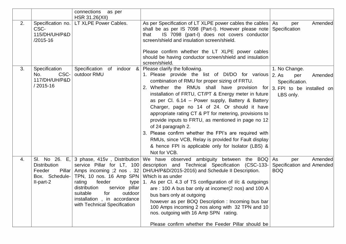
connections as per HSR 31.26(XII)
2. Specification no. CSC-115/DH/UH/P&D/2015-16
LT XLPE Power Cables. As per Specification of LT XLPE power cables the cables shall be as per IS 7098 (Part-I). However please note that IS 7098 (part-I) does not covers conductor screen/shield and insulation screen/shield. Please confirm whether the LT XLPE power cables should be having conductor screen/shield and insulation screen/shield.
As per Amended Specification
3. Specification No. CSC-117/DH/UH/P&D/ 2015-16
Specification of indoor & outdoor RMU
Please clarify the following. 1. Please provide the list of DI/DO for various
combination of RMU for proper sizing of FRTU.
2. Whether the RMUs shall have provision for
installation of FRTU, CT/PT & Energy meter in future
as per Cl. 6.14 – Power supply, Battery & Battery
Charger, page no 14 of 24. Or should it have
appropriate rating CT & PT for metering, provisions to
provide inputs to FRTU, as mentioned in page no 12
of 24 paragraph 2.
3. Please confirm whether the FPI’s are required with
RMUs, since VCB, Relay is provided for Fault display
& hence FPI is applicable only for Isolator (LBS) &
Not for VCB.
1. No Change.
2. As per Amended
Specification.
3. FPI to be installed on
LBS only.
4. Sl. No 26. E, Distribution Feeder Pillar Box. Schedule-II-part-2
3 phase, 415v , Distribution service Pillar for LT, 100 Amps incoming ;2 nos . 32 TPN, 10 nos. 16 Amp SPN rating feeder type distribution service pillar suitable for outdoor installation , in accordance with Technical Specification
We have observed ambiguity between the BOQ description and Technical Specification (CSC-133-DH/UH/P&D/2015-2016) and Schedule II Description. Which is as under 1. As per Cl. 4.3 of TS configuration of I/c & outgoings
are : 100 A bus bar only at incomer(2 nos) and 100 A
bus bars only at outgoing
however as per BOQ Description : Incoming bus bar 100 Amps incoming 2 nos along with 32 TPN and 10 nos. outgoing with 16 Amp SPN rating. Please confirm whether the Feeder Pillar should be
As per Amended Specification and Amended BOQ

supplied without MCCB’s asper TS or bus bar and MCCBs as per BOQ.
5 Sl. No 16, LT Distribution Box sealable with lock facility, Schedule-II-part-2
Material and thickness of Box Please confirm whether the Spring loaded box should be of 2 mm thickness made up of CRCA sheet as per description in schedule II part -2, or should it be made up of Glass Filled Fire Retardant engineering plastic of 3 mm thickness as per Technical Specification No. S- 163/DD-177. Please confirm.
As per Amended BOQ
6. ---- ---- Please provide the following specifications additional details which are not provided with tender documents and neither available at DHBVNL website. 1. Specification of 3Cx2.5 SqmmPVC copper insulated
and Sheathed Circular flexible wire (80/0.20mm).
2. 4Cx25 Sqmm Armoured underground cable, loose in
existing pipe or trenches complete with necessary
connections.
For 3 Core 2.50 sq.mm refer the specification no CSC-122/DH/UH/P&D/2015-16 and for 4 core 25 sq.mm. refer the specification no CSC-115/DH/UH/P&D/2015-16 or latest amendment which is available at Nigam’s web site www.dhbvn.org.in.