
Firing Order of Cylinders
21
Firing Order of Cylinders Cylinder firing order improves the distribution of the fresh charge in the manifold to the cylinders and helps the release of the exhaust gases, while at the same time suppresses torsional vibrations. These conditions are as follows. (i) Successive cylinders firing allows a recovery of charge in the manifold and minimizes interference between adjacent or nearby cylinders. Normally cylinders from opposite end of the manifold are chosen or from alternate cylinder banks in *V engines to draw alternately. This arrangement, however, becomes difficult as the number of cylinders decreases. (ii) Separating successive cylinders, which are exhausting, are even more important than for induction. It is because if the exhaust periods overlap with the cylinders, exhaust- gas back pressure may prevent escaping of products of combustion from the cylinders. (Hi) Power impulses cause winding up of the crankshaft. In addition, if the natural torsional oscillations of the shaft coincide with these disturbing impulse frequencies, torsional vibrations may take place. Therefore, in general, it is desirable to have successive power impulses to alternate ends of the crankshaft. Fig. 2.15. Single-cylinder arrangement. 2.6.1. Single-cylinder Arrangements
Transcript of Firing Order of Cylinders

Firing Order of CylindersCylinder firing order improves the distribution of the fresh charge in the manifold to thecylinders and helps the release of the exhaust gases, while at the same time suppresses torsionalvibrations. These conditions are as follows.(i) Successive cylinders firing allows a recovery of charge in the manifold and minimizesinterference between adjacent or nearby cylinders. Normally cylinders from oppositeend of the manifold are chosen or from alternate cylinder banks in *V engines to drawalternately. This arrangement, however, becomes difficult as the number of cylindersdecreases.(ii) Separating successive cylinders, which are exhausting, are even more important thanfor induction. It is because if the exhaust periods overlap with the cylinders, exhaust-gas back pressure may prevent escaping of products of combustion from the cylinders.(Hi) Power impulses cause winding up of the crankshaft. In addition, if the naturaltorsional oscillations of the shaft coincide with these disturbing impulse frequencies,torsional vibrations may take place. Therefore, in general, it is desirable to havesuccessive power impulses to alternate ends of the crankshaft.
Fig. 2.15. Single-cylinder arrangement.2.6.1.
Single-cylinder ArrangementsA single-cylinder engine has a power stroke every720 degrees/1 i.e. 720 degrees of crankshaft rotationfor a four-stroke-cycle engine. The engine has simplya single-throw crank-arm, and the rotating big-endjournal or crankpin is linked to the piston gudgeonpin by means of a connecting-rod to have both a linearand an oscillating motion (Fig. 2.15).When piston is at TDC, it is either completingcompression and about to begin power stroke or it isat the end of the exhaust stroke and beginning induction stroke. Assuming piston initially atTDC at zero angle of crankshaft rotation, it is then at BDC at 180 degrees and 540 degrees, andat TDC at 360 degrees and 720 degrees of crankshaft rotation.2.6.2.
Twin-cylinder Arrangement
A. In-line Side-by-side

An in-line side-by-side twin-cylinder engine has a powerimpulses every 720 degrees/2 i.e. 360 degrees of crankshaftrotation. The crankshaft uses a single-throw crank-arm withboth pistons and connecting-rods attached to a common big-endjournal or crankpin (Fig. 2.16).When piston 1 is at TDC, it is on the top of its compressionstroke and about to start its power stroke. Piston 2 is then atits exhaust stroke at TDC and about to begin its inductionstroke. With 180 degrees of crankshaft rotation, both pistonsare at BDC and piston 1 is about to start its exhaust stroke and piston 2 its compression stroke.A second 180 degrees of crankshaft rotation brings pistons 1 and 2 to TDC to begin theirinduction and power strokes respectively. A third 180 degrees rotation of the crankshaft movesthe pistons to BDC, and piston 1 and 2 are about to start compression and exhaust strokesrespectively. A four-stroke cycle of720 degrees is completed when fourth rotation of 180 degreesbrings the pistons to the original starting position.
B. In-line 180 Degrees-out-of-phase
With this arrangement power impulses take place at un-even intervals, i.e., at every 180 degrees and 540 degrees ofcrankshaft displacement. The cylinders are positioned parallelto each other, when piston 1 is at TDC, piston 2 is at BDC andthe crank-throws are 180 degrees out of phase with each other(Fig. 2.17). If initially piston 1 is at the end of compression andthe beginning of its power stroke, then piston 2 is at the end ofpower and at the beginning of its exhaust stroke.First rotation of crankshaft through 180 degrees bringspiston 1 to BDC, about to begin its exhaust stroke after complet-ing power stroke, while piston 2 is at TDC, at the end of exhauststroke and about start compression stroke. A second rotation of’180 degrees moves pistons 1 and 2 to TDC and BDC respective-
Fig. 2.16. In-line side-by-side twin-cylinder arrangement.

Fig. 2.17. In-line 180 degree^omt-ofphase twin-cylinder arrangement.
Fig. 2.18. Horizontally opposed twin-cylinderarrangement.ly. The piston 1 is at the end of exhaust and atthe beginning of induction stroke, while 2 isbeginning its compression after completing itsinduction stroke.The third 180 degrees rotation of thecrankshaft brings piston 1 to BDC, ending induc-tion and starting its compression stroke, whilepiston 2 is at TDC and ready for next powerstroke after completing compression stroke. Fourth 180 degrees rotation of crankshaft movespiston 1 to TDC and piston 2 to BDC bringing them to initial starting positon.
C. Horizontally Opposed
This arrangement provides power impulses at even intervals of every 360 degrees ofcrankshaft rotation. The crank-throws are 180 degrees out of phase with each other. Theconnecting-rods and pistons are positioned on opposite sides of the crankshaft, horizontallyopposed (Fig. 2.18) with the cylinder axes offset to each other. Therefore, pistons approach TDCand BDC positions together although, they move in opposite directions at all times. Assumingpistons are at TDC, piston 1 at the end of compression and the beginning of power stroke, andthen piston 2 finishes exhaust and about to start its induction stroke..First, second and third 180 degrees rotation of crankshaft bring the pistons to BDC, TDCand BDC positions respectively performing their respective strokes as indicated in the figure.Fourth 180 degrees rotation completes the cycle of events of four-stroke cycle and brings thepistons to their initial starting positions. These engines are used in small motorcars.
D. 90 Degrees *V
In this arrangement, two cylinders are positioned at 90 degrees to each other with both bigends attached to a single crankpin (Fig. 2.19). With this configuration power impulses haveuneven intervals, which take place every 270 degrees and 450 degrees of crankshaft

movement.Cylinder banks are designed to form V either at left-hand or right-hand when looking from thefront of the engine. Side-by-side connecting roads are used, and two banks of cylinders are offsetrelative to each other.Assuming piston 1 first at the end of compres-sion stroke in readiness for firing and piston 2 isthen at mid-stroke approaching TDC on either itsexhaust or its compression stroke. Let piston 2 isat mid-stroke on its exhaust stroke. Rotation ofthe crank through 450 degrees completes its ex-haust, induction, and compression strokes inreadiness for firing. At this point piston 1 is atmid-stroke on induction stroke, so rotation of thecrank through a further 270 degrees completesboth its » i action and compression strokes. Thetotal cranK-angle interval for these two firingevents adds up to 450 + 270 i.e. 720 degrees.The V-twin cylinder engines can have only a moderate degree of dynamic balance, and theiruneven filling intervals and insufficient cyclic-torque smoothness make them unsuitable for the
Fig. 2.19. V-twin cylinder arrangement.car. This case has been discussed in order to explain the basic arrangement of V-bank cylinderswith connecting-rods sharing a common crankpin. This is important engine layout.2.SJ3.
In-line Three-cylinder ArrangementA three-cylinder engine has a power impulse every 720 degrees/3 i.e. 240 degrees ofcrankshaft rotation for the four-stroke cycle operation. The crank-throws and crankpins arespaced at intervals of 120 degrees and four main journals and bearings are provided (Fig. 2.20)to support the crankshaft.With piston 1 at the top of the compression stroke and start of its power stroke, pistons 2and 3 are at 60 degrees crank-angle from BDC on their induction and exhaust strokesrespectively. A120 degrees rotation of crankshaft places piston 3 at TDC at the end of its exhauststroke and beginning of its induction stroke, and pistons 1 and 2 at 60 degrees from BDC ontheir power and compression strokes respectively.

A second 120 degrees rotation of crankshaft moves piston 2 to TDC, completing compressionstroke in readiness for its power stroke. Pistons 1 and 3 are at 60 degrees from BDC on theirrespective exhaust and induction strokes. Third 120 degrees movement brings piston 1 to TDCso that it just ends exhaust stroke and about to begin its induction stroke. Pistons 2 and 3 noware at 60 degrees from BDC on their respectivepower and compression strokes. Finally a fourth120 degrees of crankshaft rotation places piston3 at TDC on its compression stroke and ready tostart power stroke. This sequence of eventsresults in a firing order of 1, 2, 3.These engines are dynamically balanced.The extra cylinder smoothes out the cyclic torquesufficiently so that the engine stands as a com-petitor to the popular four-cylinder configura-tion. This configuration provides savings inweight and length, and has reduced reciprocatingand rotational drag, which improves fuel con-sumption.2.6.4.
Four-cylinder Arrangement
A. In-line
A four-cylinder in-line engine has a power im-pulse every 720 degrees/4 i.e. 180 degrees ofcrankshaft movement. The crankshafts have crank-throws situated at intervals of 180 degrees to eachother in the order in which the power impulses areintended. With this crankshaft arrangement (Fig.2.21), all four crank-throws lie in one plane,crankpins 1 and 4 being in phase but at 180 degreesto crankpins 2 and 3.Assuming crankpin 1 is at the top of a compres-sion stroke, crankpin 4 must be at the top of anexhaust stroke and crankshaft rotation makes then
Fig. 2.20. In-line three-cylinder arrangement.

Fig. 2.21. In-line four-cylinder arrangement.to descend on a power stroke and on an induction stroke respectively. Rotation of the crankshaftthrough 180 degrees places big-ends 1 and 4 at the bottom of their strokes, while big-ends 2 andSatthetopoftheir storkes after either a compression or an exhaust stroke. Further it is assumedthat piston 3 be the next to descend on power stroke, while piston 2 descends on an inductionstroke. The order of firing is then 1,3.A second 180 degrees movement of crankshaft positions crankpins and pistons 1 and 4 atthe top of their exhaust and power strokes respectively, so that at this point the order of firingis 1, 3, 4. A third crankshaft rotation of 180 degrees again places pistons 2 and 3 at the top oftheir stroke. As piston 3 previously descended on a power stroke, piston 2 is now on its powerstroke, so that the complete firing order is 1, 3, 4, 2. A final 180 degrees rotation completes 720degrees displacement of crankshaft in a four-stroke engine.If cylinder 2 is selected instead of cylinder 3 to fire after cylinder 1, then firing order wouldbe 1,2,4,3. Both these firing orders have equal merits and limitations with respect to crankshafttorsional wind-up and the uneven breathing intervals between adjacent cylinders. In-linefour-cylinder engines in the capacitors from 0.75 to 2.0 liters are most popular.
B. Horizontally Opposed Flat
This arrangement requires a single-plane crankshaft with crankpins spaced at 180 degreesintervals. Therefore the crank-throws are paired so that crankpins 1 ad 4 are diametricallyopposite to crankpins 2 and 3 (Fig. 2.22). Let pistons 1 and 2 are at TDC, and pistons 3 and 4at BDC for the consideration of firing order. Let piston 1 is at the end of its compression strokeand just to start power stroke, then piston 2 is completing exhaust, while pistons 3 and 4 are atpower and induction strokes respectively.Rotation of the crankshaft through 180 degrees places pistons 3 and 4 at TDC at the end oftheir respective exhaust and compression strokes andpiston 4 is about to start power stroke. Pistons 1 and2 are at BDC completing their respective power andinduction strokes. The order of firing is 1, 4. A second180 degrees of rotation brings piston 1 and 2 to TDC,

at the end of their respective exhaust and compres-sion strokes, while piston 3 and 4 are at BDC com-pleting their respective induction and power strokes.The order of firing is 1, 4, 2.A third 180 degrees rotation brings piston 3 and4 to TDC at the end of their respective compressionand exhaust strokes, while piston 1 and 2 are at BDCcompleting their respective induction and powerstroke. The complete order of firing is 1,4,2,3. A final180 degrees rotation completes 720 degrees ofcrankshaft displacement.The flat four-cylinder engine has slightly better dynamic balance than the in-line four-cylinder engine, but the smoothness of torque is equal in both the cases. The flat shape makesit suitable for rear mounted engines but opposed cylinder allow very little room for cylinder headservicing.
Fig. 2.22. Horizontally opposed flat four-cylinder arrangement.
C.60 Degrees ‘V
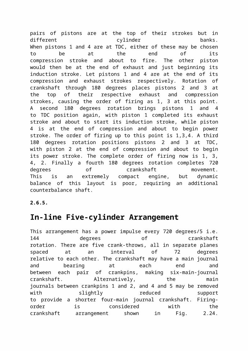
In this arrangement the cylinders fire at equally spaced intervals of 180 degrees and areplaced with numbers 1 and 2 in the left-hand bank and numbers 3 and 4 in the right-hand bank.The crankpins are unequally spaced at alternate intervals of 60 degrees and 120 degrees (Fig.2.23), and they lie in two planes when viewed from the front. Main journals and bearings areprovided at each end, with a third journal between crankpins 2 and 3. With such an arrangementpairs of pistons are at the top of their strokes but in different cylinder banks.When pistons 1 and 4 are at TDC, either of these may be chosen to be at the end of itscompression stroke and about to fire. The other pistonwould then be at the end of exhaust and just beginning itsinduction stroke. Let pistons 1 and 4 are at the end of itscompression and exhaust strokes respectively. Rotation ofcrankshaft through 180 degrees places pistons 2 and 3 atthe top of their respective exhaust and compressionstrokes, causing the order of firing as 1, 3 at this point.

A second 180 degrees rotation brings pistons 1 and 4to TDC position again, with piston 1 completed its exhauststroke and about to start its induction stroke, while piston4 is at the end of compression and about to begin powerstroke. The order of firing up to this point is 1,3,4. A third180 degrees rotation positions pistons 2 and 3 at TDC,with piston 2 at the end of compression and about to beginits power stroke. The complete order of firing now is 1, 3,4, 2. Finally a fourth 180 degrees rotation completes 720degrees of crankshaft movement.This is an extremely compact engine, but dynamicbalance of this layout is poor, requiring an additionalcounterbalance shaft.
2.6.5.
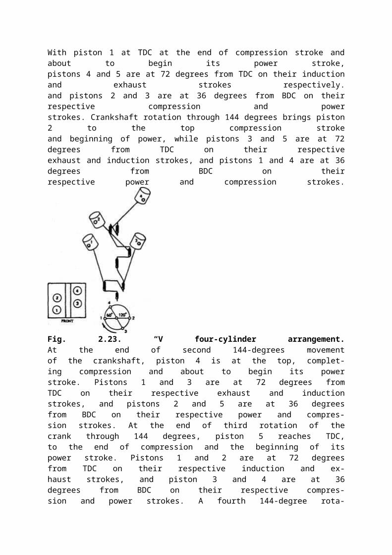
In-line Five-cylinder ArrangementThis arrangement has a power impulse every 720 degrees/5 i.e. 144 degrees of crankshaftrotation. There are five crank-throws, all in separate planes spaced at an interval of 72 degreesrelative to each other. The crankshaft may have a main journal and bearing at each end andbetween each pair of crankpins, making six-main-journal crankshaft. Alternatively, the mainjournals between crankpins 1 and 2, and 4 and 5 may be removed with slightly reduced supportto provide a shorter four-main journal crankshaft. Firing-order is considered with thecrankshaft arrangement shown in Fig. 2.24.With piston 1 at TDC at the end of compression stroke and about to begin its power stroke,pistons 4 and 5 are at 72 degrees from TDC on their induction and exhaust strokes respectively.and pistons 2 and 3 are at 36 degrees from BDC on their respective compression and powerstrokes. Crankshaft rotation through 144 degrees brings piston 2 to the top compression strokeand beginning of power, while pistons 3 and 5 are at 72 degrees from TDC on their respectiveexhaust and induction strokes, and pistons 1 and 4 are at 36 degrees from BDC on theirrespective power and compression strokes.

Fig. 2.23. “V four-cylinder arrangement.At the end of second 144-degrees movementof the crankshaft, piston 4 is at the top, complet-ing compression and about to begin its powerstroke. Pistons 1 and 3 are at 72 degrees fromTDC on their respective exhaust and inductionstrokes, and pistons 2 and 5 are at 36 degreesfrom BDC on their respective power and compres-sion strokes. At the end of third rotation of thecrank through 144 degrees, piston 5 reaches TDC,to the end of compression and the beginning of itspower stroke. Pistons 1 and 2 are at 72 degreesfrom TDC on their respective induction and ex-haust strokes, and piston 3 and 4 are at 36degrees from BDC on their respective compres-sion and power strokes. A fourth 144-degree rota-tion moves piston 3 to TDC on compression strokeand about to start power stroke. Pistons 2 and 4 are then on their induction and exhaust strokesrespectively, and pistons 1 and 5 are on their compression and power strokes respectively. Thisarrangement provides a firing order of 1,2,4, 5, 3. A final 144 degrees of rotation completes 720degrees of crankshaft displacementThe spacing of the crank-throws through an odd number of five cylinders ensures, unlikefour-cylinder arrangement, that the pistons do not all stop and start together at the top andbottom of each stroke. Therefore, this arrangement provides a very smooth drive.2.6.6.
Six-cylinder Arrangement
A. In-line
A six cylinder in-line engine has a powerimpulse every 720 degrees/6 i.e. 120 degrees ofcrankshaft rotation. The crankshaft has sixcrank-throws placed at 120 degrees out ofphase with one another, which can be arrangedonly in three planes. Therefore, the crankpinphasing is arranged in pairs (Fig. 2.25). Forheavy-duty diesel engines, seven journals andbearings are provided, at each end and be-tween adjacent crankpins. For petrol enginesonly 4 or 5 main journals are provided. Thefiring order with the crankshaft arrangementshown in Fig. 2.25 is considered.With piston 1 at the top of the compressionstroke, its opposite piston 6 is at the top of itsexhaust stroke. Rotation of crankshaft through 120 degrees brings pistons 2 and 5 to their TDCand either one of these can be arrangement to complete a compression stroke. If piston 5 isarranged to be at the end of compression and at the start of its power stroke, then piston 2 mustbe on its exhaust stroke. Rotation of crankshaft through second 120 degrees positions pistons 3
Fig. 2.25. In-line six-cylinder arrangement.
fig. 2.24. In-line five-cylinder arrangement.
and 4 at the TDC, so either one of these can be on the compression stroke. If piston 3 is madeto be on compression, piston 4 must be on its exhaust stroke.A third rotation of 120 degrees brings pistons 1 and 6 back again to TDC, where piston 6 isarranged to be on the compression and piston 1, therefore, be on its exhaust stroke. A fourth120 degrees rotation brings pistons 2 and 5 to their TDC. Piston 2 is now on its compressionand piston 5 on its exhaust stroke. Rotation of crankshaft through fifth 120 degrees brings piston3 and 4 to TDC. Piston 4 is on compression and piston 3 on its exhaust stroke. Final rotation of120 degrees completes the 720 degrees displacement of crankshaft and brings the pistons intopositions for the next cycle. This cycle provides a firing order of 1, 5, 3, 6, 2, 4.If the phasing of paired crank-throws 3 and 4 and 2 and 5 are interchanged, then a secondequally suitable firing-order of 1, 4, 2, 6, 3, 5 is achieved. This arrangement provides excellentdynamic balance and evenness of torque, and is preferred for engines larger than 2.5 litersprovided length is not a prime consideration.
B. Horizontally Opposed Flat
This six-cylinder engine has its three cylinders positioned in a horizontal plane on each sideof the crankshaft. The power impulses are timed as for the in-line six-cylinder arrangementwith every 120 degrees of crankshaft movement. The crankshaft has six crankpins spaced at 60degrees intervals around the crankshaft. Normally five main journals and bearings are used .Pairs of pistons, one from the each side of the bank reaches TDC and BDC simultaneously (Fig.2.26). Similar to the in-line six-cylinder engine, this arrangement is extremely well balanced,but its flat wide configuration makes it difficult to install at the front or rear of the car.Assume pistons 1 and 2 at TDC with piston 1 at the end of compression and about to startpower stroke and piston 2 at the end of its exhaust stroke.Pistons 3, 4, 5, and 6 are then at 60 degrees from BDC ontheir exhaust, compression, induction, and power strokesrespectively. When the crankshaft is rotated by 120degrees, pistons 3 and 4 reach at TDC at the end of theirrespective exhaust and compression strokes. Pistons 1, 2,5 and 6 are then at 60 degrees from BDC on their respec-tive power, induction, compression, and exhaust strokes.The order of firing at this point is 1, 4.A second 120 degrees movement places pistons 5 and6 at TDC, completing compression and exhaust strokesrespectively. Pistons 1, 2, 3, and 4 are then at 60 degreesfrom BDC on exhaust, compression, induction and powerstrokes respectively. The order of firing becomes 1,4,5. Athird 120 degrees rotation positions pistons 1 and 2 atTDC again, completing exhaust and compression strokesrespectively. Pistons 3, 4, 5, and 6 are then at 6 degreesfrom BDC on compression, exhaust, power, and inductionstrokes respectively. The order of firing at this point is 1,4, 5, 2,A fourth 120 degrees rotation places piston 3 and 4 at TDC again, completing compression

and exhaust strokes respectively. Pistons 1,2,5, and 6 are then at 60 degrees from BDC on their
Fig. 2.26. Horizontally opposed flatsix-cylinder arrangement.induction, power, exhaust and compression strokes respectively. The order of firing becomes 1,4, 5, 2, 3. A fifth 120 degrees rotation brings pistons 5 and 6 to TDC again, completing exhaustand compression strokes respectively. Pistons 1, 2, 3, and 4 are then at 60 degrees from BDCon compression, exhaust, power, and induction strokes respectively. The complete firing orderis 1,4,5,2,3,6. A final rotation of 120 degrees completes 720 degrees of crankshaft displacementmaking ready for next cycle to begin.
C. 60 Degrees *V Six-cylinder
In this layout the cylinders fire at equally spaced intervals of 120 degrees. The cylinders arelocated with numbers 1,2, and 3 in the left-hand bank and numbers 4, 5, and 6 in the right-handbank. The crankshaft uses six crankpins to support the shaft, equally spaced at intervals of 60degrees and arranged to lie in three planes. There are four main journals and bearings placedat each end and between pairs of crankpins to support the shaft, thus providing a relativelyshort but rigid construction (Fig. 2.27). The dynamic balance is relatively good providing a shortcompact engine compared with the in-line six-cylinder arrangement.Four firing orders are possible, but three of these involve consecutive firing of three cylindersin each bank and only the fourth enables cylinders to be fired alternatively from each bankhaving a firing order as 1, 4, 2, 5, 3, 6. This arrangement also offers the best selection from thetorsional vibration consideration. With this arrangement, pairs of pistons in different cylinderbanks are at the top of their strokes.Consider pistons 1 and 5 are at TDC after compression and exhaust strokes respectively sothat piston 1 is about to start its power stroke and piston 5 in its induction stroke. A120 degreesrotation of the crankshaft brings pistons 3 and 4 to the top of exhaust and compression strokes

respectively. At this point, the order of firing is 1, 4. A second rotation of 120 degrees positionspistons 2 and 6 at TDC on compression and exhauststrokes respectively. The order of firing at this pointis 1, 4, 2.A third 120 degrees rotation places pistons 1 and5 at TDC on exhaust and compression strokes respec-tively so that at this point the order of firing is 1,4,2, 5. A fourth 120 degrees rotation of crankshaftpositions pistons 3 and 4 to TDC on compression andexhaust strokes respectively. The order of firing be-comes 1, 4, 2, 5, 3. A fifth 120 degrees of rotationbrings pistons 2 and 6 at the top of exhaust andcompression strokes respectively. The final order offiring is therefore 1,4,2,5,3, 6. The next 120 degreesrotation completes 720 degrees of crankshaft dis-placement so that ready for the next cycle of events.2.6.7.
Eight-cylinder Arrangement
A. In-line Straight
This arrangement has a power impulse every 720degrees/8 i.e. 90 degrees of crankshaft movement.The crank-throws are spaced at intervals of 90degrees to each other in the order the power impul-
Fig. 2.27. Vsix-cylinder arrangement.ses intended (Fig. 2.28). There can only be four relative angular positions. Therefore, thecrankpin phasing is arranged in pairs and hence the crank-throws lie in two planes. Five ornine main journals are required to support the crankshaft. The layout presented in the figure

resembles a four-cylinder crankshaft in one plane with twin cranks at either end forming asecond plane at right angles to the first. This arrangement is sometimes known as a split fourinline eight.Let pistons 1 and 8 are at TDC, with piston 1 at the end of compression about to fire andpiston 8 at the end of its exhaust stroke. Pistons 3 and 6 are at mid-stroke on their respectiveexhaust and compression strokes ; pistons 2 and 7 at BDC at the end of induction and powerstrokes respectively; and pistons 4 and 5 at mid-stroke on their respective power and inductionstrokes.Rotation of the crankshaft through 90 degrees positions pistons 3 and 6 at TDC at the endof exhaust and compression strokes respectively. Pistons 2 and 7 are then at mid-stroke on theirrespective compression and exhaust strokes ; pistons 4 and 5 at BDC at the end of power andinduction strokes respectively; and pistons 1 and 8 at mid-stroke on their respective power andinduction strokes. The firing order at this positon is 1, 6.A second 90 degrees rotation of crankshaft provides the firing order at this positon as 1,6,2. Third degrees rotation position gives the firing order as 1, 6, 2, 5; fourth 90 degrees rotationposition as 1, 6, 2, 5, 8 ; fifth 90 degrees rotation position as 1, 6, 2, 5, 8, 3 and sixth 90 degreesmovement positon as 1, 6, 2, 5, 8, 3, 7. The seventh 90 degrees movement completes the firingorders after 630 degrees rotation as 1, 6, 2, 5, 8, 3^ 7, 4.A further 90 degrees movement makesa total of 720 degrees, and completes twocrankshaft revolutions or four strokes inreadiness for the next cycle to begin. Byarranging different pairs of crank-throws,other firing orders have been used in theengines are 1, 5, 2, 6, 4, 8, 3, 7 and 1, 7, 3, 8,4, 6, 2, 5.To have extra capacity to pull largeloads, the crankshaft may be extended withtwo more cylinders. This design though isdynamically balanced there can be torsionalvibrations problem and also the extendedlength may be difficult to accommodate insome trucks.
B. 90 Degrees *V Eight with Single-plane Crankshaft
Similar to the two-plane crankshaft of the in-line eight-cylinder, the single-plane layoutused for the V-eight provides a power impulse every 90 degrees of crankshaft rotation. Thesingle-plane crankshaft uses four crankpins paired to have both outer and both inner crankpinsin phase. Each crankpin carries two connecting rod big ends, and normally five main journalsare used to support the crankshaft (Fig. 2.29).

Fig. 2.28. In-line straight eight-cylinder arrangement.
Fig. 2.29. 90 degrees V eight-cylinderarrangment with single-plane crankshaft.Let pistons 1 and 4 remain at TDC, with piston 1at the end of compression and about to fire, and piston4 at the end of its exhaust stroke. Pistons 2 and 3 arethen at BDC at the end of power and induction strokesrespectively ; pistons 5 and 8 are at mid-stroke onexhaust and compression strokes respectively ; andpistons 6 and 7 are at mid-stroke on induction andpower strokes respectively.A first, second, third, fourth, fifth, and sixth 90degrees rotation of crankshaft provide the firing orderin their respective positions as, 1, 8; 1, 8, 3; 1, 8, 3, 6 ;1, 8, 3, 6, 4 ; 1, 8, 3, 6, 4, 5 ; and 1, 8, 3, 6, 4, 5, 2. Thefinal firing order is completed after 360 degrees ofrotation i.e. seventh 90 degrees movement of the
crankshaft and is 1, 8, 3, 6, 4, 5, 2, 7.An eighth 90 degrees of rotation completes 720degrees of crankshaft movement of four-stroke cycleand in readiness for the next cycle of events.The single-plane crankshaft, unlike the two planeV-eight crankshaft, provides at least 180 degrees ex-haust pulse intervals between adjacent cylinders, andwith single manifold modification this can be extendedto 360 degrees before pulse interference can occur.
C. 90 degrees *V Eight-cylinder Arrangement
with Two-plane CrankshaftThis arrangement of cylinders provides the firing atequally phased intervals of 90 degrees. The cylinders arearranged with numbers 1, 2, 3, and 4 in the left-handband and numbers 5, 6, 7, and 8 in the right-hand bandas shown in Fig. 2.30. The two-plane crankshaft usespairs of crank-throws phased at intervals of 90 degrees.Each crankpin incorporates two separate connecting-rods, hinged to pistons in different cylinder banks. Amain journal and bearing is provided at each end andbetween adjacent crankpin. Since two connecting-rodsshare a common crankpin these five-main-journal-crankshafts are extremely short and less complicated.The two-plane crankshaft has a dynamic balance farsuperior to that of the single-plane crankshaft and henceis more popular.Consider the order of cylinder power strokes occur-ring as the crankshaft rotates as shown in the Fig. 2.30.With piston 1 at TDC after its compression stroke and at
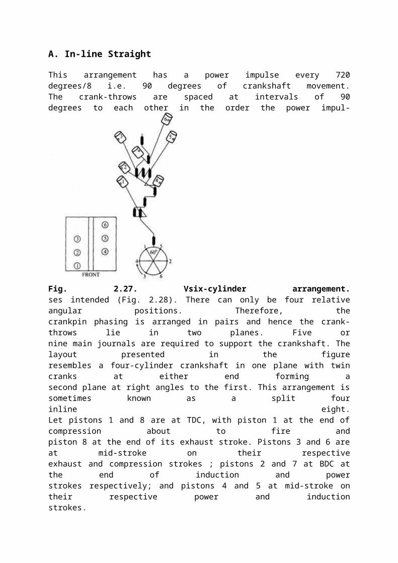
Fig. 2.30. 90 degrees V eight-cylinderarrangement with two-plane crankshaft.the beginning of the power, piston 5 is at mid-stroke on compression. Piston 3 and 7 are then atmid-stroke exhaust and at the beginning of exhaust respectively; pistons 4 and 8 are at thebeginning of the compression and at mid-stroke on induction respectively; and pistons 2 and 6are at mid-stroke power and at the beginning of induction respectively.With subsequent first, second, third, fourth, fifth, sixth and seventh 90 degrees of rotationsof the crankshaft provide the firing order in this case as 1, 5, 4, 8, 6, 3, 7, 2. A final eighth 90degrees of rotation completes 720 degrees of crankshaft displacement