Firewall and SmartDefense - asm.mdstorage.asm.md/docs/CheckPoint NGX R65/CheckPoint_R65...Reporter,...
420
Firewall and SmartDefense Administration Guide Version NGX R65 701682 April 27, 2008
Transcript of Firewall and SmartDefense - asm.mdstorage.asm.md/docs/CheckPoint NGX R65/CheckPoint_R65...Reporter,...
Firewall and SmartDefenseAdministration Guide
Version NGX R65
701682 April 27, 2008


© 2003-2007 Check Point Software Technologies Ltd.
All rights reserved. This product and related documentation are protected by copyright and distributed under licensing restricting their use, copying, distribution, and decompilation. No part of this product or related documentation may be reproduced in any form or by any means without prior written authorization of Check Point. While every precaution has been taken in the preparation of this book, Check Point assumes no responsibility for errors or omissions. This publication and features described herein are subject to change without notice.
RESTRICTED RIGHTS LEGEND:
Use, duplication, or disclosure by the government is subject to restrictions as set forth in subparagraph (c)(1)(ii) of the Rights in Technical Data and Computer Software clause at DFARS 252.227-7013 and FAR 52.227-19.
TRADEMARKS:
©2003-2008 Check Point Software Technologies Ltd. All rights reserved. Check Point, AlertAdvisor, Application Intelligence, Check Point Endpoint Security, Check Point Express, Check Point Express CI, the Check Point logo, ClusterXL, Confidence Indexing, ConnectControl, Connectra, Connectra Accelerator Card, Cooperative Enforcement, Cooperative Security Alliance, CoreXL, CoSa, DefenseNet, Dynamic Shielding Architecture, Eventia, Eventia Analyzer, Eventia Reporter, Eventia Suite, FireWall-1, FireWall-1 GX, FireWall-1 SecureServer, FloodGate-1, Hacker ID, Hybrid Detection Engine, IMsecure, INSPECT, INSPECT XL, Integrity, Integrity Clientless Security, Integrity SecureClient, InterSpect, IPS-1, IQ Engine, MailSafe, NG, NGX, Open Security Extension, OPSEC, OSFirewall, Pointsec, Pointsec Mobile, Pointsec PC, Pointsec Protector, Policy Lifecycle Management, Provider-1, PureAdvantage, PURE Security, the puresecurity logo, Safe@Home, Safe@Office, SecureClient, SecureClient Mobile, SecureKnowledge, SecurePlatform, SecurePlatform Pro, SecuRemote, SecureServer, SecureUpdate, SecureXL, SecureXL Turbocard, Security Management Portal, Sentivist, SiteManager-1, SmartCenter, SmartCenter Express, SmartCenter Power, SmartCenter Pro, SmartCenter UTM, SmartConsole, SmartDashboard, SmartDefense, SmartDefense Advisor, Smarter Security, SmartLSM, SmartMap, SmartPortal, SmartUpdate, SmartView, SmartView Monitor, SmartView Reporter, SmartView Status, SmartViewTracker, SMP, SMP On-Demand, SofaWare, SSL Network Extender, Stateful Clustering, TrueVector, Turbocard, UAM, UserAuthority, User-to-Address Mapping, UTM-1, UTM-1 Edge, UTM-1 Edge Industrial, UTM-1 Total Security, VPN-1, VPN-1 Accelerator Card, VPN-1 Edge, VPN-1 Express, VPN-1 Express CI, VPN-1 Power, VPN-1 Power Multi-core, VPN-1 Power VSX, VPN-1 Pro, VPN-1 SecureClient, VPN-1 SecuRemote, VPN-1 SecureServer, VPN-1 UTM, VPN-1 UTM Edge, VPN-1 VSX, Web Intelligence, ZoneAlarm, ZoneAlarm Anti-Spyware, ZoneAlarm Antivirus, ZoneAlarm ForceField, ZoneAlarm Internet Security Suite, ZoneAlarm Pro, ZoneAlarm Secure Wireless Router, Zone Labs, and the Zone Labs logo are trademarks or registered trademarks of Check Point Software Technologies Ltd. or its affiliates. ZoneAlarm is a Check Point Software Technologies, Inc. Company. All other product names mentioned herein are trademarks or registered trademarks of their respective owners. The products described in this document are protected by U.S. Patent No. 5,606,668, 5,835,726, 5,987,611, 6,496,935, 6,873,988, 6,850,943, and 7,165,076 and may be protected by other U.S. Patents, foreign patents, or pending applications
.For third party notices, see: THIRD PARTY TRADEMARKS AND COPYRIGHTS.


Table of Contents 5
Contents
Preface Who Should Use This Guide.............................................................................. 16Summary of Contents ....................................................................................... 17
Section 1: Network Access .......................................................................... 17Section 2: Connectivity ............................................................................... 18Section 3: SmartDefense ............................................................................. 19Section 4: Application Intelligence ............................................................... 19Section 5: Web Security .............................................................................. 21Section 6: Appendices ................................................................................ 21
Related Documentation .................................................................................... 22More Information ............................................................................................. 25Feedback ........................................................................................................ 26
Network Access
Chapter 1 Access Control The Need for Access Control ............................................................................. 30Solution for Secure Access Control .................................................................... 31
Access Control at the Network Boundary ....................................................... 31The Rule Base ............................................................................................ 32Example Access Control Rule ....................................................................... 33Rule Base Elements .................................................................................... 33Implied Rules............................................................................................. 34Preventing IP Spoofing ................................................................................ 35Multicast Access Control ............................................................................. 37Cooperative Enforcement ............................................................................. 40End Point Quarantine (EPQ) - Intel(r) AMT .................................................... 42
Special Considerations for Access Control .......................................................... 44Spoofing Protection..................................................................................... 44Simplicity .................................................................................................. 44Basic Rules ................................................................................................ 45Rule Order ................................................................................................. 45Topology Considerations: DMZ ..................................................................... 45X11 Service................................................................................................ 46Editing Implied Rules.................................................................................. 46
Configuring Access Control ............................................................................... 47Defining Access Control Rules...................................................................... 47Defining a Basic Access Control Policy.......................................................... 47Configuring Anti-Spoofing............................................................................ 49Configuring Multicast Access Control ............................................................ 50

6
Configuring Cooperative Enforcement ........................................................... 51Configuring End Point Quarantine (EPQ) - Intel(r) AMT................................... 52Activating EPQ ........................................................................................... 52Connection Authentication Data ................................................................... 53Quarantine Policy Data................................................................................ 54Encrypting the Password.............................................................................. 55Malicious Activity Script and Alert ................................................................ 55Logging Activity .......................................................................................... 57To Quarantine a Machine Manually............................................................... 57
Chapter 2 Authentication The Need for Authentication ............................................................................. 60The VPN-1 Solution for Authentication .............................................................. 61
Introduction to VPN-1 Authentication ........................................................... 61Authentication Schemes.............................................................................. 62Authentication Methods............................................................................... 64
Configuring Authentication ............................................................................... 73Creating Users and Groups........................................................................... 73Configuring User Authentication................................................................... 75Configuring Session Authentication .............................................................. 76Configuring Client Authentication ................................................................. 81Configuring Authentication Tracking ............................................................. 87Configuring a VPN-1 Gateway to use RADIUS ................................................ 87Granting User Access Using RADIUS Server Groups ....................................... 90Associating a RADIUS Server with a VPN-1 Gateway ...................................... 92Configuring a VPN-1 Gateway to use SecurID ................................................ 93Configuring a VPN-1 Gateway to use TACACS+ .............................................. 95Configuring Policy for Groups of Windows Users............................................. 96
Connectivity
Chapter 3 Network Address Translation (NAT) The Need to Conceal IP Addresses .................................................................. 100Check Point Solution for Network Address Translation ....................................... 101
Public and Private IP addresses ................................................................. 101NAT in VPN-1 .......................................................................................... 102Static NAT ............................................................................................... 103Hide NAT................................................................................................. 104Automatic and Manual NAT Rules .............................................................. 105Automatic Hide NAT for Internal Networks .................................................. 106Address Translation Rule Base ................................................................... 107Bidirectional NAT ..................................................................................... 108Understanding Automatically Generated Rules............................................. 109Port Translation ........................................................................................ 111
Table of Contents 7
NAT and Anti-Spoofing.............................................................................. 111Routing Issues.......................................................................................... 111Disabling NAT in a VPN Tunnel.................................................................. 113
Planning Considerations for NAT ..................................................................... 114Hide Versus Static .................................................................................... 114Automatic Versus Manual Rules ................................................................. 114Choosing the Hide Address in Hide NAT...................................................... 115
Configuring NAT ............................................................................................ 116General Steps for Configuring NAT ............................................................. 116Basic Configuration (Network Node with Hide NAT) ..................................... 117Sample Configuration (Static and Hide NAT) ............................................... 118Sample Configuration (Using Manual Rules for Port Translation) ................... 120Configuring Automatic Hide NAT for Internal Networks................................. 121
Advanced NAT Configuration .......................................................................... 122Allowing Connections Between Translated Objects on Different Gateway Interfaces
122Enabling Communication for Internal Networks with Overlapping IP Addresses 123SmartCenter Behind NAT .......................................................................... 127IP Pool NAT ............................................................................................. 131
Chapter 4 ISP Redundancy The Need for ISP Link Redundancy ................................................................. 138Solution for ISP Link Redundancy ................................................................... 139
ISP Redundancy Overview ......................................................................... 139ISP Redundancy Operational Modes ........................................................... 140Monitoring the ISP Links ........................................................................... 141How ISP Redundancy Works ...................................................................... 141ISP Redundancy Script ............................................................................. 143Manually Changing the Link Status (fw isp_link) .......................................... 143ISP Redundancy Deployments.................................................................... 144ISP Redundancy and VPNs ........................................................................ 147
Considerations for ISP Link Redundancy .......................................................... 149Choosing the Deployment .......................................................................... 149Choosing the Redundancy Mode................................................................. 149
Configuring ISP Link Redundancy ................................................................... 150Introduction to ISP Link Redundancy Configuration ..................................... 150Registering the Domain and Obtaining IP Addresses..................................... 150DNS Server Configuration for Incoming Connections .................................... 151Dialup Link Setup for Incoming Connections ............................................... 152SmartDashboard Configuration ................................................................... 152Configuring the Default Route for the ISP Redundancy Gateway .................... 154
Chapter 5 ConnectControl - Server Load Balancing The Need for Server Load Balancing ................................................................ 158ConnectControl Solution for Server Load Balancing ........................................... 159
Introduction to ConnectControl................................................................... 159Load-Balancing Methods ........................................................................... 160ConnectControl Packet Flow....................................................................... 161

8
Logical Server Types ................................................................................. 161Persistent Server Mode.............................................................................. 164Server Availability ..................................................................................... 166Load Measuring ........................................................................................ 166
Configuring ConnectControl ............................................................................ 167
Chapter 6 Bridge Mode Introduction to Bridge Mode ........................................................................... 170
Limitations in Bridge Mode........................................................................ 171Managing a Gateway in Bridge Mode .......................................................... 171
Configuring Bridge Mode ................................................................................ 172Bridging Interfaces ................................................................................... 172Configuring Anti-Spoofing.......................................................................... 172Displaying the Bridge Configuration ............................................................ 173
SmartDefense
Chapter 7 SmartDefense The Need for SmartDefense ........................................................................... 178SmartDefense Solution................................................................................... 180
Introducing SmartDefense ......................................................................... 180Defending Against the Next Generation of Threats........................................ 181Network and Transport Layers .................................................................... 182Web Attack Protection............................................................................... 182How SmartDefense Works .......................................................................... 183Online Updates......................................................................................... 184Categorizing SmartDefense Capabilities ...................................................... 184SmartDefense Profiles ............................................................................... 186Monitor-Only Mode ................................................................................... 187
Network Security ........................................................................................... 188Japanese Language Support for SmartDefense Protections............................ 188SmartDefense Single Profile View............................................................... 189Denial of Service ...................................................................................... 190IP and ICMP ............................................................................................ 191TCP......................................................................................................... 191Fingerprint Scrambling.............................................................................. 192Successive Events..................................................................................... 192DShield Storm Center................................................................................ 192Port Scan................................................................................................. 193Dynamic Ports .......................................................................................... 194
Application Intelligence.................................................................................. 195Mail ........................................................................................................ 195FTP ......................................................................................................... 195Microsoft Networks ................................................................................... 195
Table of Contents 9
Peer-to-Peer ............................................................................................. 196Instant Messengers ................................................................................... 196DNS ........................................................................................................ 196VoIP ........................................................................................................ 196SNMP...................................................................................................... 197
Web Intelligence............................................................................................ 198Web Intelligence Protections...................................................................... 198Web Intelligence Technologies ................................................................... 199Web Intelligence and ClusterXL Gateway Clusters ........................................ 199Web Content Protections ........................................................................... 200Customizable Error Page............................................................................ 200Connectivity Versus Security Considerations ................................................ 201Web Security Performance Considerations ................................................... 203Backward Compatibility Options for HTTP Protocol Inspection....................... 205Web Intelligence License Enforcement........................................................ 205Understanding HTTP Sessions, Connections and URLs................................. 207
Configuring SmartDefense .............................................................................. 210Updating SmartDefense with the Latest Defenses ........................................ 210
SmartDefense Services................................................................................... 211Download Updates .................................................................................... 211Advisories ................................................................................................ 212Security Best Practices.............................................................................. 213
Configuring SmartDefense Profiles .................................................................. 214Creating Profiles ....................................................................................... 214Assign a Profile to the Gateway .................................................................. 214View Protected Gateways by a Profile .......................................................... 215
SmartDefense StormCenter Module ................................................................. 216The Need for Cooperation in Intrusion Detection .......................................... 216Check Point Solution for Storm Center Integration........................................ 217Planning Considerations ............................................................................ 221Configuring Storm Center Integration .......................................................... 222
Application Intelligence
Chapter 8 Content Inspection Anti Virus Protection ...................................................................................... 228
Introduction to Integrated Anti Virus Protection ........................................... 228Architecture ............................................................................................. 229Configuring Integrated Anti Virus Scanning.................................................. 229Database Updates..................................................................................... 230Understanding Scan By Direction and Scan By IP ........................................ 231Scanning by Direction: Selecting Data to Scan............................................. 235File Type Recognition................................................................................ 237Continuous Download................................................................................ 238

10
Logging and Monitoring ............................................................................. 239File Size Limitations and Scanning............................................................. 240VPN-1 UTM Edge Anti Virus ...................................................................... 242
Web Filtering................................................................................................. 243Introduction to Web Filtering ..................................................................... 243Terminology ............................................................................................. 244Architecture ............................................................................................. 244Configuring Web Filtering .......................................................................... 245
Chapter 9 Securing Voice Over IP (VoIP) The Need to Secure Voice Over IP ................................................................... 248Introduction to the Check Point Solution for Secure VoIP................................... 249Control Signalling and Media Protocols ............................................................ 250VoIP Handover............................................................................................... 251
When to Enforce Handover......................................................................... 252VoIP Application Intelligence .......................................................................... 253
Introduction to VoIP Application Intelligence............................................... 253Restricting Handover Locations Using a VoIP Domain................................... 254Controlling Signalling and Media Connections ............................................. 255Preventing Denial of Service Attacks........................................................... 255Protocol-Specific Application Intelligence ................................................... 256
VoIP Logging ................................................................................................. 257Protocol-Specific Security............................................................................... 258Securing SIP-Based VoIP................................................................................ 259
SIP Architectural Elements in the Security Rule Base .................................. 260Supported SIP RFCs and Standards............................................................ 261Secured SIP Topologies and NAT Support ................................................... 262Application Intelligence for SIP.................................................................. 264SmartDefense Application Intelligence for SIP............................................. 265Synchronizing User Information ................................................................. 267SIP Services............................................................................................. 267Using SIP on a Non-Default Port ................................................................ 268ClusterXL and Multicast Support for SIP ..................................................... 268Securing SIP-Based Instant Messenger Applications .................................... 268Configuring SIP-Based VoIP....................................................................... 269
Troubleshooting SIP....................................................................................... 278Securing H.323-Based VoIP ........................................................................... 279
H.323 Architectural Elements in the Security Rule Base .............................. 279Supported H.323 RFCs and Standards ....................................................... 280Secured H.323 Topologies and NAT Support............................................... 280Application Intelligence for H.323 ............................................................. 283SmartDefense Application Intelligence Settings for H.323............................ 284H.323 Services ........................................................................................ 286Configuring H.323-Based VoIP .................................................................. 287
Securing MGCP-Based VoIP............................................................................ 303The Need for MGCP .................................................................................. 303MGCP Protocol and Devices ....................................................................... 304MGCP Network Security and Application Intelligence ................................... 305
Table of Contents 11
Secured MGCP Topologies and NAT Support ............................................... 307Synchronizing User Information.................................................................. 308Configuring MGCP-Based VoIP ................................................................... 309
Securing SCCP-Based VoIP............................................................................. 311The SCCP Protocol.................................................................................... 311SCCP Devices........................................................................................... 312SCCP Network Security and Application Intelligence .................................... 312ClusterXL Support for SCCP ....................................................................... 313Configuring SCCP-Based VoIP .................................................................... 313
Chapter 10 Securing Instant Messaging Applications The Need to Secure Instant Messenger Applications.......................................... 320Introduction to Instant Messenger Security....................................................... 321Understanding Instant Messenger Security ....................................................... 322NAT Support for MSN Messenger over SIP ....................................................... 323NAT Support for MSN Messenger over MSNMS ................................................ 324Logging Instant Messenger Applications........................................................... 324Configuring SIP-based Instant Messengers ....................................................... 325Configuring MSN Messenger over MSNMS ....................................................... 327Configuring Skype, Yahoo and ICQ and Other Instant Messengers....................... 328
Chapter 11 Microsoft Networking Services (CIFS) Security Securing Microsoft Networking Services (CIFS)................................................. 330Restricting Access to Servers and Shares (CIFS Resource) ................................. 331
Chapter 12 FTP Security Introduction to FTP Content Security ............................................................... 334FTP Enforcement by the VPN-1 Kernel ............................................................ 334FTP Enforcement by the FTP Security Server.................................................... 335
Control Allowed Protocol Commands ........................................................... 335Maintaining Integrity of Other Protected Services ......................................... 335Avoiding Vulnerabilities in FTP Applications ................................................ 335Content Security via the FTP Resource........................................................ 336
Configuring Restricted Access to Specific Directories ........................................ 337
Chapter 13 Content Security The Need for Content Security ........................................................................ 340Check Point Solution for Content Security ........................................................ 341
Introduction to Content Security................................................................. 341Security Servers........................................................................................ 342Deploying OPSEC Servers .......................................................................... 343CVP Servers for Anti-Virus and Malicious Content Protection ......................... 344Using URL Filtering to Limit Web Surfers.................................................... 348The TCP Security Server ............................................................................ 351
Configuring Content Security .......................................................................... 352Resources: What They Are and How to Use Them......................................... 352Creating a Resource and Using it in the Rule Base....................................... 353
12
Configuring Anti-Virus Checking for Incoming Email..................................... 354Configuring CVP Checking for Web Traffic with Improved Performance........... 356Configuring URL Filtering with a UFP Server ............................................... 356Performing CVP or UFP Inspection on any TCP Service................................. 360
Advanced CVP Configuration: CVP Chaining and Load Sharing ........................... 361Introduction to CVP Chaining and Load Sharing ........................................... 361CVP Chaining ........................................................................................... 361CVP Load Sharing ..................................................................................... 363Combining CVP Chaining and Load Sharing................................................. 364Configuring CVP Chaining and Load Sharing................................................ 364
Chapter 14 Services with Application Intelligence Introduction to Services with Application Intelligence........................................ 368DCE-RPC ...................................................................................................... 368SSLv3 Service ............................................................................................... 369SSHv2 Service .............................................................................................. 369FTP_BASIC Protocol Type............................................................................... 369Domain_UDP Service ..................................................................................... 370Point-to-Point Tunneling Protocol (PPTP)......................................................... 371
Configuring for PPTP................................................................................. 371Blocking Visitor Mode (TCPT).......................................................................... 373
Introduction to TCPT................................................................................. 373Why Block Visitor Mode and Outgoing TCPT?............................................... 373How VPN-1 Identifies TCPT ....................................................................... 373When to Block Outgoing TCPT ................................................................... 373Configuration of Visitor Mode Blocking........................................................ 374
Web Security
Chapter 15 Web Content Protection Introduction to Web Content Protection ........................................................... 378Web Content Security via the Security Rule Base .............................................. 379
What is a URI Resource? ........................................................................... 379Filtering URLs, Schemes and Methods by Source and Destination ................. 379Basic URL Filtering................................................................................... 380URL Logging ............................................................................................ 380Java and ActiveX Security .......................................................................... 381
Securing XML Web Services (SOAP) ................................................................ 382Understanding HTTP Sessions, Connections and URLs...................................... 383
HTTP Request Example............................................................................. 383HTTP Response Example........................................................................... 384HTTP Connections .................................................................................... 384Understanding URLs................................................................................. 385
Connectivity Versus Security Considerations for Web Surfers .............................. 386

Table of Contents 13
Allowing or Restricting Content .................................................................. 386Content Compression ................................................................................ 387
Factors Affecting HTTP Security Server Performance......................................... 388The Number of Simultaneous Security Server Connections............................ 388How To Run Multiple Instances of the HTTP Security Server ......................... 389
Configuring Web Content Protection ................................................................ 390Blocking URL-based Attacks Using a URI Resource ..................................... 390Configuring URL Logging........................................................................... 391Configuring Basic URL Filtering ................................................................. 392
Appendices
Appendix A Security BeforeVPN-1 Activation
Achieving Security Before VPN-1 Activation ..................................................... 396Boot Security ................................................................................................ 396
Control of IP Forwarding on Boot ................................................................ 396The Default Filter...................................................................................... 397
The Initial Policy ........................................................................................... 399Default Filter and Initial Policy Configuration ................................................... 402
Verifying Default Filter or Initial Policy Loading............................................ 402Change the Default Filter to a Drop Filter .................................................... 403User-Defined Default Filter ........................................................................ 403Using the Default Filter for Maintenance..................................................... 404To Unload a Default Filter or an Initial Policy .............................................. 404If You Cannot Complete Reboot After Installation......................................... 404Command Line Reference for Default Filter and Initial Policy........................ 405
Appendix B Command Line Interface
Index...........................................................................................................417

14

15
Preface PPreface
In This Chapter
Who Should Use This Guide page 16
Summary of Contents page 17
Related Documentation page 22
More Information page 25
Feedback page 26
Who Should Use This Guide
16
Who Should Use This GuideThis guide is intended for administrators responsible for maintaining network security within an enterprise, including policy management and user support.
This guide assumes a basic understanding of the following:
• System administration
• The underlying operating system
• Internet protocols (for example, IP, TCP and UDP)
Summary of Contents
Preface 17
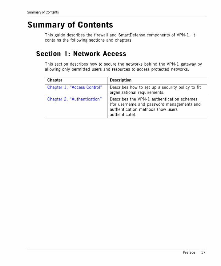
Summary of ContentsThis guide describes the firewall and SmartDefense components of VPN-1. It contains the following sections and chapters:
Section 1: Network AccessThis section describes how to secure the networks behind the VPN-1 gateway by allowing only permitted users and resources to access protected networks.
Chapter Description
Chapter 1, “Access Control” Describes how to set up a security policy to fit organizational requirements.
Chapter 2, “Authentication” Describes the VPN-1 authentication schemes (for username and password management) and authentication methods (how users authenticate).
Section 2: Connectivity
18
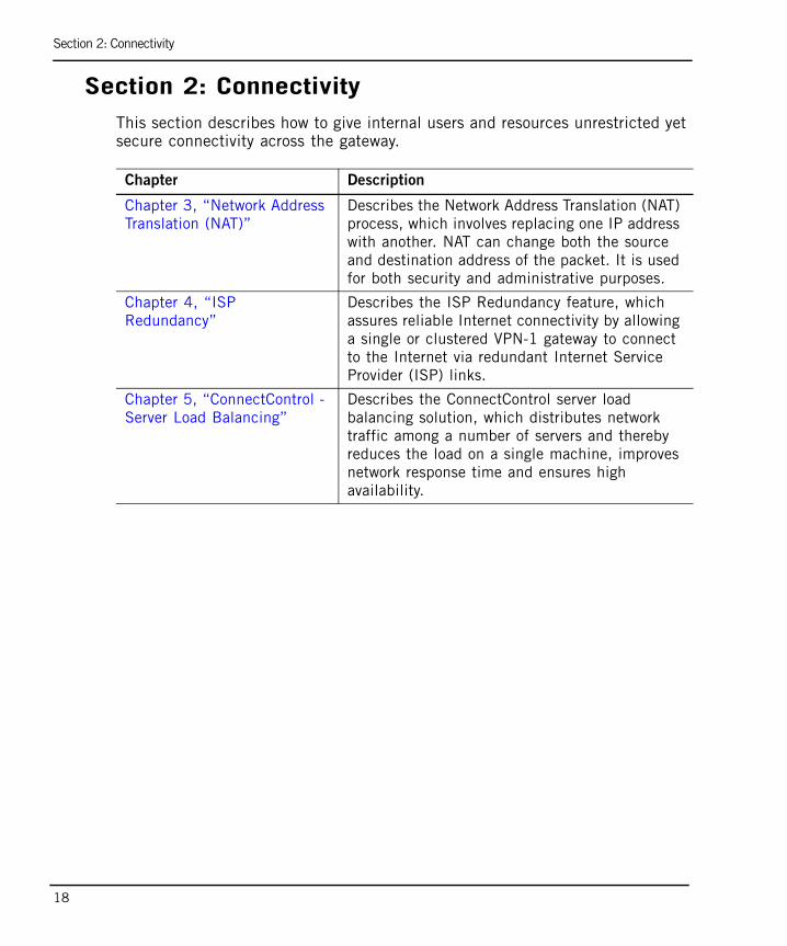
Section 2: ConnectivityThis section describes how to give internal users and resources unrestricted yet secure connectivity across the gateway.
Chapter Description
Chapter 3, “Network Address Translation (NAT)”
Describes the Network Address Translation (NAT) process, which involves replacing one IP address with another. NAT can change both the source and destination address of the packet. It is used for both security and administrative purposes.
Chapter 4, “ISP Redundancy”
Describes the ISP Redundancy feature, which assures reliable Internet connectivity by allowing a single or clustered VPN-1 gateway to connect to the Internet via redundant Internet Service Provider (ISP) links.
Chapter 5, “ConnectControl - Server Load Balancing”
Describes the ConnectControl server load balancing solution, which distributes network traffic among a number of servers and thereby reduces the load on a single machine, improves network response time and ensures high availability.
Section 3: SmartDefense
Preface 19
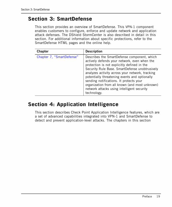
Section 3: SmartDefenseThis section provides an overview of SmartDefense. This VPN-1 component enables customers to configure, enforce and update network and application attack defenses. The DShield StormCenter is also described in detail in this section. For additional information about specific protections, refer to the SmartDefense HTML pages and the online help.
Section 4: Application IntelligenceThis section describes Check Point Application Intelligence features, which are a set of advanced capabilities integrated into VPN-1 and SmartDefense to detect and prevent application-level attacks. The chapters in this section
Chapter Description
Chapter 7, “SmartDefense” Describes the SmartDefense component, which actively defends your network, even when the protection is not explicitly defined in the Security Rule Base. SmartDefense unobtrusively analyzes activity across your network, tracking potentially threatening events and optionally sending notifications. It protects your organization from all known (and most unknown) network attacks using intelligent security technology.
Section 4: Application Intelligence
20
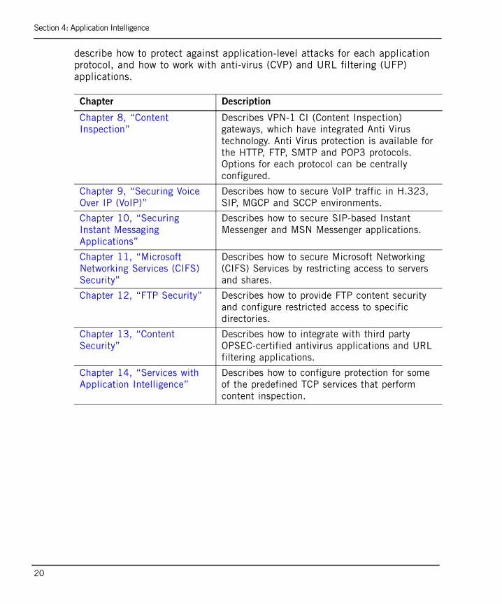
describe how to protect against application-level attacks for each application protocol, and how to work with anti-virus (CVP) and URL filtering (UFP) applications.
Chapter Description
Chapter 8, “Content Inspection”
Describes VPN-1 CI (Content Inspection) gateways, which have integrated Anti Virus technology. Anti Virus protection is available for the HTTP, FTP, SMTP and POP3 protocols. Options for each protocol can be centrally configured.
Chapter 9, “Securing Voice Over IP (VoIP)”
Describes how to secure VoIP traffic in H.323, SIP, MGCP and SCCP environments.
Chapter 10, “Securing Instant Messaging Applications”
Describes how to secure SIP-based Instant Messenger and MSN Messenger applications.
Chapter 11, “Microsoft Networking Services (CIFS) Security”
Describes how to secure Microsoft Networking (CIFS) Services by restricting access to servers and shares.
Chapter 12, “FTP Security” Describes how to provide FTP content security and configure restricted access to specific directories.
Chapter 13, “Content Security”
Describes how to integrate with third party OPSEC-certified antivirus applications and URL filtering applications.
Chapter 14, “Services with Application Intelligence”
Describes how to configure protection for some of the predefined TCP services that perform content inspection.
Section 5: Web Security
Preface 21
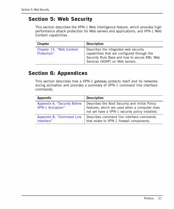
Section 5: Web SecurityThis section describes the VPN-1 Web Intelligence feature, which provides high performance attack protection for Web servers and applications, and VPN-1 Web Content capabilities.
Section 6: AppendicesThis section describes how a VPN-1 gateway protects itself and its networks during activation and provides a summary of VPN-1 command line interface commands.
Chapter Description
Chapter 15, “Web Content Protection”
Describes the integrated web security capabilities that are configured through the Security Rule Base and how to secure XML Web Services (SOAP) on Web servers.
Appendix Description
Appendix A, “Security Before VPN-1 Activation”
Describes the Boot Security and Initial Policy features, which are used when a computer does not yet have a VPN-1 security policy installed.
Appendix B, “Command Line Interface”
Describes command line interface commands that relate to VPN-1 firewall components.
Related Documentation
22
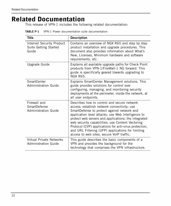
Related DocumentationThis release of VPN-1 includes the following related documentation:
TABLE P-1 VPN-1 Power documentation suite documentation
Title Description
Internet Security Product Suite Getting Started Guide
Contains an overview of NGX R65 and step by step product installation and upgrade procedures. This document also provides information about What’s New, Licenses, Minimum hardware and software requirements, etc.
Upgrade Guide Explains all available upgrade paths for Check Point products from VPN-1/FireWall-1 NG forward. This guide is specifically geared towards upgrading to NGX R65.
SmartCenter Administration Guide
Explains SmartCenter Management solutions. This guide provides solutions for control over configuring, managing, and monitoring security deployments at the perimeter, inside the network, at all user endpoints.
Firewall and SmartDefense Administration Guide
Describes how to control and secure network access; establish network connectivity; use SmartDefense to protect against network and application level attacks; use Web Intelligence to protect web servers and applications; the integrated web security capabilities; use Content Vectoring Protocol (CVP) applications for anti-virus protection, and URL Filtering (UFP) applications for limiting access to web sites; secure VoIP traffic.
Virtual Private Networks Administration Guide
This guide describes the basic components of a VPN and provides the background for the technology that comprises the VPN infrastructure.
Related Documentation
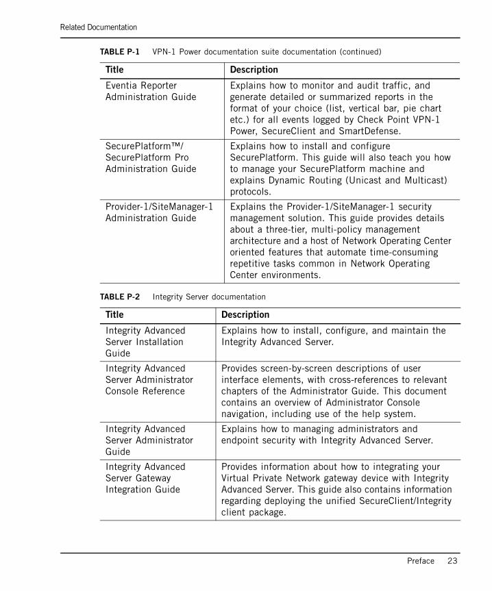
Preface 23
Eventia Reporter Administration Guide
Explains how to monitor and audit traffic, and generate detailed or summarized reports in the format of your choice (list, vertical bar, pie chart etc.) for all events logged by Check Point VPN-1 Power, SecureClient and SmartDefense.
SecurePlatform™/ SecurePlatform Pro Administration Guide
Explains how to install and configure SecurePlatform. This guide will also teach you how to manage your SecurePlatform machine and explains Dynamic Routing (Unicast and Multicast) protocols.
Provider-1/SiteManager-1 Administration Guide
Explains the Provider-1/SiteManager-1 security management solution. This guide provides details about a three-tier, multi-policy management architecture and a host of Network Operating Center oriented features that automate time-consuming repetitive tasks common in Network Operating Center environments.
TABLE P-2 Integrity Server documentation
Title Description
Integrity Advanced Server Installation Guide
Explains how to install, configure, and maintain the Integrity Advanced Server.
Integrity Advanced Server Administrator Console Reference
Provides screen-by-screen descriptions of user interface elements, with cross-references to relevant chapters of the Administrator Guide. This document contains an overview of Administrator Console navigation, including use of the help system.
Integrity Advanced Server Administrator Guide
Explains how to managing administrators and endpoint security with Integrity Advanced Server.
Integrity Advanced Server Gateway Integration Guide
Provides information about how to integrating your Virtual Private Network gateway device with Integrity Advanced Server. This guide also contains information regarding deploying the unified SecureClient/Integrity client package.
TABLE P-1 VPN-1 Power documentation suite documentation (continued)
Title Description
Related Documentation
24
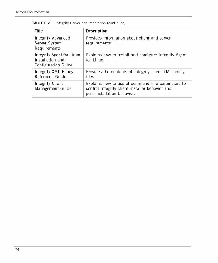
Integrity Advanced Server System Requirements
Provides information about client and server requirements.
Integrity Agent for Linux Installation and Configuration Guide
Explains how to install and configure Integrity Agent for Linux.
Integrity XML Policy Reference Guide
Provides the contents of Integrity client XML policy files.
Integrity Client Management Guide
Explains how to use of command line parameters to control Integrity client installer behavior and post-installation behavior.
TABLE P-2 Integrity Server documentation (continued)
Title Description

More Information
Preface 25
More Information• For additional technical information regarding Check Point products, refer to
Check Point’s SecureKnowledge at https://secureknowledge.checkpoint.com/.
• To view the latest version of this document in the Check Point User Center, go to: http://www.checkpoint.com/support/technical/documents.

Feedback
26
FeedbackCheck Point is engaged in a continuous effort to improve its documentation. Please help us by sending your comments to:

Network AccessThis section describes how to secure the networks behind the VPN-1 gateway by allowing only permitted users and resources to access protected networks.


29
Chapter 1Access Control
In This Chapter
The Need for Access Control page 30
Solution for Secure Access Control page 31
Special Considerations for Access Control page 44
Configuring Access Control page 47
The Need for Access Control
30
The Need for Access ControlNetwork administrators need the means to securely control access to resources such as networks, hosts, network services and protocols. Determining what resources can be accessed, and how, is the responsibility of authorization, or Access Control. Determining who can access these resources is the responsibility of User Authentication (for additional information, refer to Chapter 2, “Authentication”).
Solution for Secure Access Control
Chapter 1 Access Control 31
Solution for Secure Access ControlIn This Section
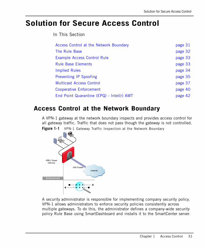
Access Control at the Network BoundaryA VPN-1 gateway at the network boundary inspects and provides access control for all gateway traffic. Traffic that does not pass though the gateway is not controlled. Figure 1-1 VPN-1 Gateway Traffic Inspection at the Network Boundary
A security administrator is responsible for implementing company security policy. VPN-1 allows administrators to enforce security policies consistently across multiple gateways. To do this, the administrator defines a company-wide security policy Rule Base using SmartDashboard and installs it to the SmartCenter server.
Access Control at the Network Boundary page 31
The Rule Base page 32
Example Access Control Rule page 33
Rule Base Elements page 33
Implied Rules page 34
Preventing IP Spoofing page 35
Multicast Access Control page 37
Cooperative Enforcement page 40
End Point Quarantine (EPQ) - Intel(r) AMT page 42
Solution for Secure Access Control
32
SmartDashboard is a SmartConsole client application that administrators use to define and apply security policies to gateways. Granular security policy control is possible by applying specific rules to specific gateways.
VPN-1 provides secure access control because of its granular understanding of all underlying services and applications traveling on the network. Stateful Inspection technology provides full application level awareness and comprehensive access control for more than 150 predefined applications, services and protocols as well as the ability to specify and define custom services.
Stateful Inspection extracts state-related information required for security decisions from all application levels and maintains this information in dynamic state tables that are used to evaluate subsequent connection attempts. For additional technical information on Stateful Inspection, refer to the Check Point Technical Note at: http://www.checkpoint.com/products/downloads/firewall-1_statefulinspection.pdf
The Rule BaseA security policy is implemented by means of ordered set of rules in the security Rule Base. A well defined security policy is essential to an effective security solution.
The fundamental principle of the Rule Base is that all actions that are not explicitly permitted are prohibited. The Rule Base is a collection of rules that determine which communication traffic is permitted and which is blocked. Rule parameters include the source and destination of the communication, the services and protocols that can be used and at what times, and tracking options. Reviewing SmartView Tracker traffic logs and alerts is an crucial aspect of security management.
VPN-1 inspects packets in a sequential manner. Once VPN-1 receives a packet from a connection, it inspects it according to the first rule in the Rule Base, and then the second and so on. Once VPN-1 finds an applicable rule, it stops inspecting and applies that rule to the packet. If no applicable rule is found in the Rule Base, the packet is blocked. It is important to understand that the first matching rule applies to the packet, not necessarily the rule that best applies.
Solution for Secure Access Control
Chapter 1 Access Control 33
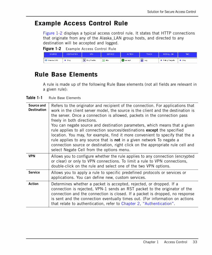
Example Access Control RuleFigure 1-2 displays a typical access control rule. It states that HTTP connections that originate from any of the Alaska_LAN group hosts, and directed to any destination will be accepted and logged. Figure 1-2 Example Access Control Rule
Rule Base ElementsA rule is made up of the following Rule Base elements (not all fields are relevant in a given rule):
Table 1-1 Rule Base Elements
Source and
DestinationRefers to the originator and recipient of the connection. For applications that work in the client server model, the source is the client and the destination is the server. Once a connection is allowed, packets in the connection pass freely in both directions. You can negate source and destination parameters, which means that a given rule applies to all connection sources/destinations except the specified location. You may, for example, find it more convenient to specify that the a rule applies to any source that is not in a given network To negate a connection source or destination, right click on the appropriate rule cell and select Negate Cell from the options menu.
VPN Allows you to configure whether the rule applies to any connection (encrypted or clear) or only to VPN connections. To limit a rule to VPN connections, double-click on the rule and select one of the two VPN options.
Service Allows you to apply a rule to specific predefined protocols or services or applications. You can define new, custom services.
Action Determines whether a packet is accepted, rejected, or dropped. If a connection is rejected, VPN-1 sends an RST packet to the originator of the connection and the connection is closed. If a packet is dropped, no response is sent and the connection eventually times out. (For information on actions that relate to authentication, refer to Chapter 2, “Authentication”.
Solution for Secure Access Control
34
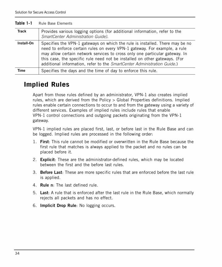
Implied RulesApart from those rules defined by an administrator, VPN-1 also creates implied rules, which are derived from the Policy > Global Properties definitions. Implied rules enable certain connections to occur to and from the gateway using a variety of different services. Examples of implied rules include rules that enable VPN-1 control connections and outgoing packets originating from the VPN-1 gateway.
VPN-1 implied rules are placed first, last, or before last in the Rule Base and can be logged. Implied rules are processed in the following order:
1. First: This rule cannot be modified or overwritten in the Rule Base because the first rule that matches is always applied to the packet and no rules can be placed before it.
2. Explicit: These are the administrator-defined rules, which may be located between the first and the before last rules.
3. Before Last: These are more specific rules that are enforced before the last rule is applied.
4. Rule n: The last defined rule.
5. Last: A rule that is enforced after the last rule in the Rule Base, which normally rejects all packets and has no effect.
6. Implicit Drop Rule: No logging occurs.
Track Provides various logging options (for additional information, refer to the SmartCenter Administration Guide).
Install-On Specifies the VPN-1 gateways on which the rule is installed. There may be no need to enforce certain rules on every VPN-1 gateway. For example, a rule may allow certain network services to cross only one particular gateway. In this case, the specific rule need not be installed on other gateways. (For additional information, refer to the SmartCenter Administration Guide.)
Time Specifies the days and the time of day to enforce this rule.
Table 1-1 Rule Base Elements

Solution for Secure Access Control
Chapter 1 Access Control 35
Preventing IP SpoofingIP spoofing occurs when an intruder attempts to gain unauthorized access by changing a packet's IP address to appear as though it originated from network node with higher access privileges.
Note - It is important to ensure that all communication originates from its apparent source.
Anti-spoofing protection verifies that packets originate from and are destined to the correct interfaces on the gateway. It confirms which packets actually come from the specified internal network interface. It also verifies that once a packet is routed, it goes through the proper interface.
A packet coming from an external interface, even if it has a spoofed internal IP address, is blocked because the VPN-1 anti-spoofing feature detects that the packet arrived from the wrong interface. Figure 1-3 illustrates the anti-spoofing process. Figure 1-3 Anti-Spoofing Process
On Alaska_GW, VPN-1 ensures that:
• All incoming packets to interface IF1 come from the Internet.
• All incoming packets to interface IF2 come from Alaska_LAN or, Alaska_RND_LAN or Florida_LAN.

Solution for Secure Access Control
36
On Alaska_RND_GW, VPN-1 ensures that:
• All incoming packets to interface IF3 come from Alaska_LAN, Florida_LAN or the Internet.
• All incoming packets to interface IF4 come from Alaka_RND_LAN.
When configuring anti-spoofing, you need to specify in the interface topology definitions whether the interfaces lead to the Internet (defined as External) or an internal network (defined as Internal). Figure 1-3 illustrates whether the gateway interfaces are internal or external in the interface topology definitions.
Excluding Specific Internal Addresses from Anti-Spoofing ProtectionIn some cases, it may be necessary to allow packets with source addresses that belong to an internal network to enter the gateway through an external interface. This may be useful if an external application assigns internal IP addresses to external clients. In this case, you can specify that anti-spoofing checks are not made on packets from specified internal networks. For example, in Figure 1-3, it is possible to specify that packets with source addresses in Alaska_RND_LAN are allowed to enter interface IF1.
What Are Legal Addresses? Legal addresses are those addresses that are permitted to enter a VPN-1 gateway interface. Legal addresses are determined by the network topology. When configuring VPN-1 anti-spoofing protection, the administrator specifies the legal IP addresses behind the interface. The Get Interfaces with Topology option automatically defines the interface and its topology and creates network objects. VPN-1 obtains this information by reading routing table entries.
Additional InformationFor additional information on anti-spoofing protection planning, refer to “Spoofing Protection” on page 44.
For additional information on anti-spoofing configuration, refer to “Configuring Anti-Spoofing” on page 49.

Solution for Secure Access Control
Chapter 1 Access Control 37
Multicast Access Control
In This Section
Introduction to Multicast IPMulticast IP transmits a single message to a predefined group of recipients. an example of this is distributing real-time audio and video to a set of hosts that have joined a distributed conference.
Multicast is similar to radio and TV where only those people who have tuned their tuners to a selected frequency receive the information. With multicast you hear the channel you are interested in, but not the others.
IP multicasting applications send one copy of each datagram (IP packet) and address it to a group of computers that want to receive it. This technique sends datagrams to a group of recipients (at the multicast address) rather than to a single recipient (at a unicast address). The routers in the network forward the datagrams to only those routers and hosts that want to receive them.
The Internet Engineering Task Force (IETF) has developed multicast communication standards that define:
• Multicast routing protocols
• Dynamic registration
• IP multicast group addressing
Multicast Routing ProtocolsMulticast routing protocols communicate information between multicast groups. Examples of multicast routing protocols include Protocol-Independent Multicast (PIM), Distance Vector Multicast Routing Protocol (DVMRP), and Multicast Extensions to OSPF (MOSPF).
Introduction to Multicast IP page 37
Multicast Routing Protocols page 37
Dynamic Registration Using IGMP page 38
IP Multicast Group Addressing page 38
Per-Interface Multicast Restrictions page 39
Solution for Secure Access Control
38
Dynamic Registration Using IGMPHosts use the Internet Group Management Protocol (IGMP) to let the nearest multicast router know if they want to belong to a particular multicast group. Hosts can leave or join the group at any time. IGMP is defined in RFC 1112.
IP Multicast Group Addressing The IP address area has four sections: Class A, Class B, Class C, and Class D. Class A, B, and C addresses are used for unicast traffic. Class D addresses are reserved for multicast traffic and are allocated dynamically.
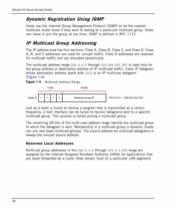
The multicast address range 224.0.0.0 through 239.255.255.255 is used only for the group address or destination address of IP multicast traffic. Every IP datagram whose destination address starts with 1110 is an IP multicast datagram (Figure 1-4). Figure 1-4 Multicast Address Range
Just as a radio is tuned to receive a program that is transmitted at a certain frequency, a host interface can be tuned to receive datagrams sent to a specific multicast group. This process is called joining a multicast group.
The remaining 28 bits of the multi-case address range identify the multicast group to which the datagram is sent. Membership in a multicast group is dynamic (hosts can join and leave multicast groups). The source address for multicast datagrams is always the unicast source address.
Reserved Local Addresses
Multicast group addresses in the 224.0.0.0 through 224.0.0.255 range are assigned by the Internet Assigned Numbers Authority (IANA) for applications that are never forwarded by a router (they remain local on a particular LAN segment).
Solution for Secure Access Control
Chapter 1 Access Control 39
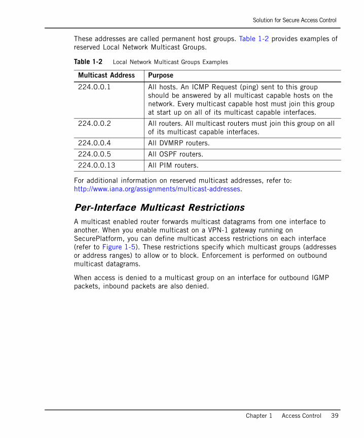
These addresses are called permanent host groups. Table 1-2 provides examples of reserved Local Network Multicast Groups.
For additional information on reserved multicast addresses, refer to: http://www.iana.org/assignments/multicast-addresses.
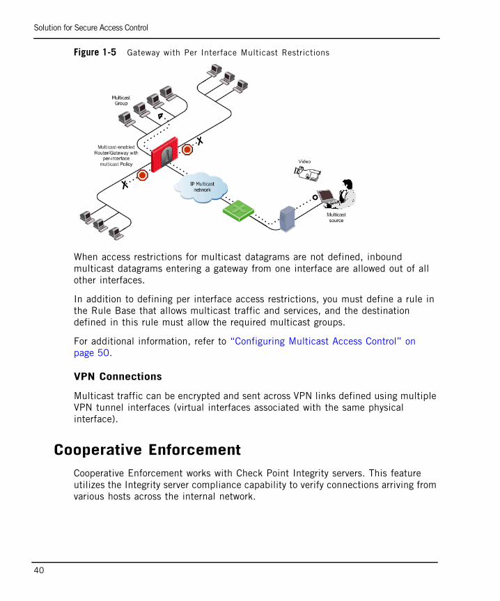
Per-Interface Multicast RestrictionsA multicast enabled router forwards multicast datagrams from one interface to another. When you enable multicast on a VPN-1 gateway running on SecurePlatform, you can define multicast access restrictions on each interface (refer to Figure 1-5). These restrictions specify which multicast groups (addresses or address ranges) to allow or to block. Enforcement is performed on outbound multicast datagrams.
When access is denied to a multicast group on an interface for outbound IGMP packets, inbound packets are also denied.
Table 1-2 Local Network Multicast Groups Examples
Multicast Address Purpose
224.0.0.1 All hosts. An ICMP Request (ping) sent to this group should be answered by all multicast capable hosts on the network. Every multicast capable host must join this group at start up on all of its multicast capable interfaces.
224.0.0.2 All routers. All multicast routers must join this group on all of its multicast capable interfaces.
224.0.0.4 All DVMRP routers.
224.0.0.5 All OSPF routers.
224.0.0.13 All PIM routers.
Solution for Secure Access Control
40
Figure 1-5 Gateway with Per Interface Multicast Restrictions
When access restrictions for multicast datagrams are not defined, inbound multicast datagrams entering a gateway from one interface are allowed out of all other interfaces.
In addition to defining per interface access restrictions, you must define a rule in the Rule Base that allows multicast traffic and services, and the destination defined in this rule must allow the required multicast groups.
For additional information, refer to “Configuring Multicast Access Control” on page 50.
VPN Connections
Multicast traffic can be encrypted and sent across VPN links defined using multiple VPN tunnel interfaces (virtual interfaces associated with the same physical interface).
Cooperative EnforcementCooperative Enforcement works with Check Point Integrity servers. This feature utilizes the Integrity server compliance capability to verify connections arriving from various hosts across the internal network.
Solution for Secure Access Control
Chapter 1 Access Control 41
Integrity server is a centrally managed, multi-layered endpoint security solution that employs policy-based security enforcement for internal and remote PCs. Easily deployed and managed, the Integrity server mitigates the risk of hackers, worms, spyware, and other security threats.
Features such as predefined policy templates, an intuitive web-based management interface, and PC firewall and application privilege controls, enable administrators to develop, manage, and enforce Cooperative Enforcement quickly and easily.
Using Cooperative Enforcement, any host initiating a connection through a gateway is tested for compliance. This increases the integrity of the network because it prevents hosts with malicious software components from accessing the network.
This feature acts as a middle-man between hosts managed by an Integrity server and the Integrity server itself. It relies on the Integrity server compliance feature, which defines whether a host is secure and can block connections that do not meet the defined prerequisites of software components.
The following is a typical Cooperative Enforcement workflow:
1. A host opens a connection to the network through a firewall gateway. The first packet from the client to the server is allowed. It is only on the first server's reply to the client that the Cooperative Enforcement feature begins to perform.
2. The firewall checks for host compliance in its tables and queries the Integrity server, if required.
3. Upon receiving a reply, connections from compliant hosts are allowed and connections from non-compliant hosts are blocked.
When activating the cooperative enforcement feature on a gateway, the following implied rules are automatically enabled:
1. Allow all firewall GUI clients to connect to the integrity server via HTTP or HTTPS (port 80 or 443).
2. Allow all internal clients to access the Integrity server via the firewall for heartbeats.
3. Allow the firewall to communicate with the Integrity server on port 5054.
If additional access permissions are required (such as allow external clients to connect to the integrity server, or for other machines to access the administration portion of the Integrity server), explicit rules should be defined.
If additional access permissions are required (such as allow external clients to connect to the integrity server, or for other machines to access the administration portion of the Integrity server), explicit rules should be defined.
Solution for Secure Access Control
42
Enforcement ModeWhen in enforcement mode, noncompliant host connections are blocked by the firewall endpoint security feature. For HTTP connections, the host is notified that it is noncompliant. The user can then perform appropriate actions to achieve compliance. For example, the user may upgrade the version of the Integrity client.
NAT EnvironmentsCooperative Enforcement feature is not supported by all the NAT configurations.
In order for Cooperative Enforcement to work in a NAT environment, the enforcement module and the Integrity Server must relate to the same IP address of a specific client. Therefore, when NAT is used, if NAT is causing the Client IP received by gateway to be different than the Client IP received by the Integrity Server, Cooperative Enforcement will not work properly.
Monitor Only Deployment ModeIn the “monitor only” deployment mode, the firewall requests authorization statuses from the Integrity server but, regardless of the received statuses, connections are not dropped. In addition (if configured by the administrator) the Cooperative Enforcement feature generates logs regardless of the deployment mode.
For configuration details, see “Configuring Cooperative Enforcement” on page 51.
End Point Quarantine (EPQ) - Intel(r) AMTEnd Point Quarantine (using Intel® AMT) gives the administrator the ability to place a malicious user’s machine under quarantine whenever malicious activity takes place according to the security policy configuration.
EPQ isolates the malicious machine by installing a security policy on the machine where the malicious activity originated. The policy restricts both inbound and outbound traffic flowing from that machine. As a result, the machine is isolated from the rest of the network and is prevented from causing any further problems.
It is recommended to enable anti-spoofing to maximize the security protection. Even with anti-spoofing enabled, the following protections will not work properly with EPQ and may cause hosts to be put into quarantine:
• All DOS protections
• Packet sanity
Solution for Secure Access Control
Chapter 1 Access Control 43
• Max ping size
• IP fragment
• Network quota
• Small pmtu
EPQ is supported on SecurePlatform and Linux platforms.
For configuration details, see “Configuring End Point Quarantine (EPQ) - Intel(r) AMT” on page 52.
Special Considerations for Access Control
44
Special Considerations for Access ControlIn This Section
Spoofing ProtectionIf your network is not protected against IP address spoofing, your access control rules are ineffective and it is easy for attackers to gain access by changing the source address of the packet. For this reason, ensure that you configure anti-spoofing protection on every interface of the VPN-1 gateway, including internal interfaces. For configuration information, refer to “Configuring Access Control” on page 47.
SimplicityThe key to effective firewall protection is a simple Rule Base. One of the greatest dangers to the security of your organization is misconfiguration. For example, a user may try to sneak spoofed, fragmented packets past your firewall if you have accidentally allowed unrestricted messaging protocols. To keep your Rule Base simple, ensure that it is concise and therefore easy to understand and maintain. The more rules you have, the more likely you are to make a mistake.
Spoofing Protection page 44
Simplicity page 44
Basic Rules page 45
Rule Order page 45
Topology Considerations: DMZ page 45
Editing Implied Rules page 46
Defining Access Control Rules page 47
Special Considerations for Access Control
Chapter 1 Access Control 45
Basic RulesWhen creating rules, ensure that you allow only traffic that you want. Consider traffic initiated and crossing the firewall from both the protected and unprotected sides of the firewall.
The following basic access control rules are recommended for every Rule Base:
• A Stealth Rule to prevent direct access to the VPN-1 gateway.
• A Cleanup Rule to drop all traffic that is not permitted by the previous rules. There is an implied rule that does this, but the Cleanup Rule allows you to log such access attempts.
Remember that the fundamental concept behind the Rule Base is that actions that are not explicitly permitted are prohibited.
Rule OrderRule order is a critical aspect of an effective Rule Base. Having the same rules, but putting them in a different order, can radically alter the effectiveness of your firewall. It is best to place more specific rules first and more general rules last. This order prevents a general rule from being applied before a more specific rule and protects your firewall from misconfigurations.
Topology Considerations: DMZIf you have servers that are externally accessible from the Internet, it is recommended to create a demilitarized zone (DMZ). The DMZ isolates all servers that are accessible from untrusted sources, such as the Internet, so that if one of those servers is compromised, the intruder only has limited access to other externally accessible servers. Servers in the DMZ are accessible from any network, and all externally accessible servers should be located in the DMZ. Servers in the DMZ should be as secure as possible. Do not allow the DMZ to initiate connections into the internal network, other than for specific applications such as UserAuthority.
Special Considerations for Access Control
46
X11 ServiceThe X11 (X Window System Version 11) graphics display system is the standard graphics system for the Unix environment. To enable X11, you must create a specific rule using the X11 service. If you select Any as the Source or Destination, the X11 service is not included because when using the X11 service, the GUI application acts as the server rather than the client.
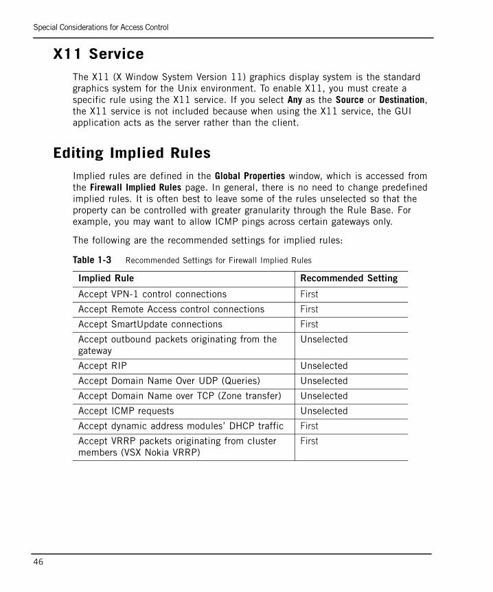
Editing Implied RulesImplied rules are defined in the Global Properties window, which is accessed from the Firewall Implied Rules page. In general, there is no need to change predefined implied rules. It is often best to leave some of the rules unselected so that the property can be controlled with greater granularity through the Rule Base. For example, you may want to allow ICMP pings across certain gateways only.
The following are the recommended settings for implied rules:
Table 1-3 Recommended Settings for Firewall Implied Rules
Implied Rule Recommended Setting
Accept VPN-1 control connections First
Accept Remote Access control connections First
Accept SmartUpdate connections First
Accept outbound packets originating from the gateway
Unselected
Accept RIP Unselected
Accept Domain Name Over UDP (Queries) Unselected
Accept Domain Name over TCP (Zone transfer) Unselected
Accept ICMP requests Unselected
Accept dynamic address modules’ DHCP traffic First
Accept VRRP packets originating from cluster members (VSX Nokia VRRP)
First

Configuring Access Control
Chapter 1 Access Control 47
Configuring Access ControlIn This Section
Defining Access Control RulesTo view an example of an access control rule, refer to Figure 1-3 on page 35.
To define access control rules. perform the following steps using SmartDashboard (for additional information, refer to the SmartCenter Administration Guide):
1. Define network objects for each network and host using SmartDashboard.
2. Click the Security tab in the Rule Base.
3. From the SmartDashboard menu, select Rules > Add Rule and then select either Bottom, Top, Below, or Above.
4. Right-click in the Source and Destination columns and select Add....
5. Select a network object and click OK.
6. Right-click in the Service column and select Add....
7. Select a service or a service group and click OK.
8. Right-click in the Action column and select Accept, Drop, or Reject.
9. Right-click in the Track column and select Add....
10. Select one of the tracking options.
Defining a Basic Access Control PolicyThe Access Control policy is required to:
• Allow internal users access to the Internet.
• Allow all users access to the servers on the DMZ network.
Defining Access Control Rules page 47
Defining a Basic Access Control Policy page 47
Configuring Anti-Spoofing page 49
Configuring Multicast Access Control page 50
Configuring Cooperative Enforcement page 51
Configuring End Point Quarantine (EPQ) - Intel(r) AMT page 52
Configuring Access Control
48
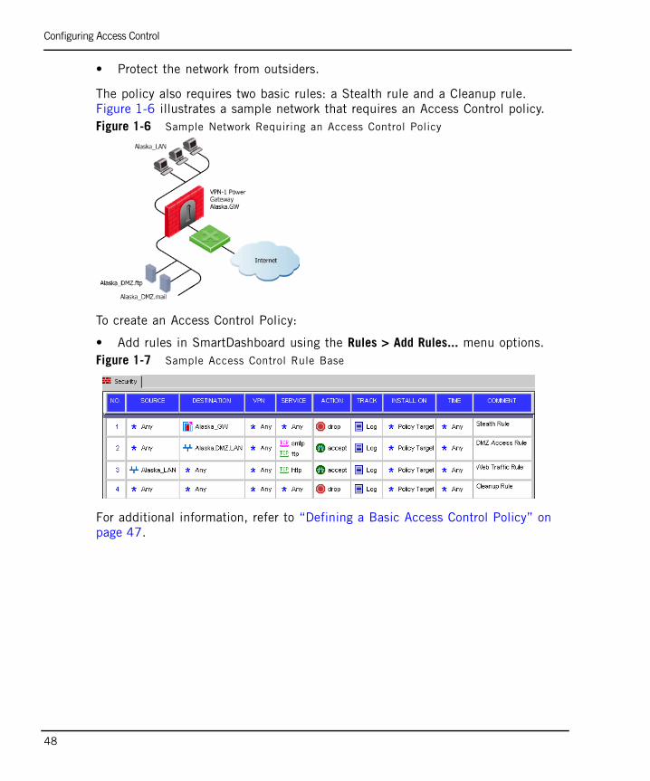
• Protect the network from outsiders.
The policy also requires two basic rules: a Stealth rule and a Cleanup rule. Figure 1-6 illustrates a sample network that requires an Access Control policy.Figure 1-6 Sample Network Requiring an Access Control Policy
To create an Access Control Policy:
• Add rules in SmartDashboard using the Rules > Add Rules... menu options.Figure 1-7 Sample Access Control Rule Base
For additional information, refer to “Defining a Basic Access Control Policy” on page 47.
Configuring Access Control
Chapter 1 Access Control 49
Configuring Anti-SpoofingIt is important to configure anti-spoofing protection on every interface of every VPN-1 gateway, including internal interfaces. The following configuration example describes how to define anti-spoofing parameters on external and internal interfaces.
Defining Addresses for External InterfacesTo define a valid address for external interfaces:
1. In SmartDashboard, select Manage > Network Objects.
2. Select a gateway and click the Edit button.
3. From the Network Properties list, select Topology.
4. Select Get > Interfaces to obtain interface information of the gateway machine.
5. Select the interface that faces the Internet and click Edit.
6. In the Interface Properties window, click Topology, and then select External (leads out to the Internet).
7. Select Perform Anti-Spoofing based on interface topology.
8. To ensure that anti-spoofing verification does not occur for addresses coming from certain internal networks into the external interface, define a network object that represents those internal networks. Select Don't check packets from: and then select the network object from the drop-down list.
9. Under Spoof Tracking, select Log and then click OK.
Defining Addresses for Internal InterfacesTo define a valid address for internal interfaces:
1. In SmartDashboard, select Manage > Network Objects.
2. Select the Check Point gateway and right-click Edit.
3. From the Properties list, select Topology.
4. Select Get > Interfaces to obtain interface information of the gateway machine.
5. Under the Name column, select the internal interface and click Edit.
6. In the Interface Properties window, click Topology, and then select Internal (leads to the local network).
7. Under IP Addresses behind this interface, do one of the following:
Configuring Access Control
50
• If there is only one network behind the interface, select Network defined by the interface IP and Net Mask.
• If there is more than one network behind the interface, define a group network object that consists of all the networks behind the interface by selecting Specific and the group.
8. To verify Perform Anti-Spoofing based on interface topology, under Spoof Tracking, select Log and click OK.
9. Repeat step 1 to step 8 for all internal interfaces.
10. Install the security policy.
Configuring Multicast Access ControlFor additional information on multicast access control, refer to: “Multicast Access Control” on page 37.
To configure multicast access control:
1. In the gateway General Properties page, ensure that the gateway version is specified correctly. (A per-interface multicast policy can be defined for gateways of versions R60 or higher.)
2. In the Topology page, edit an interface.
3. In the Multicast Restrictions tab of the Interface Properties window, (Figure 1-8), select the Drop Multicast packets by the following conditions option.
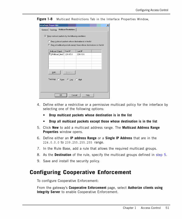
Configuring Access Control
Chapter 1 Access Control 51
Figure 1-8 Multicast Restrictions Tab in the Interface Properties Window,
4. Define either a restrictive or a permissive multicast policy for the interface by selecting one of the following options:
• Drop multicast packets whose destination is in the list
• Drop all multicast packets except those whose destination is in the list
5. Click New to add a multicast address range. The Multicast Address Range Properties window opens.
6. Define either an IP address Range or a Single IP Address that are in the 224.0.0.0 to 239.255.255.255 range.
7. In the Rule Base, add a rule that allows the required multicast groups.
8. As the Destination of the rule, specify the multicast groups defined in step 5.
9. Save and install the security policy.
Configuring Cooperative EnforcementTo configure Cooperative Enforcement:
From the gateway’s Cooperative Enforcement page, select Authorize clients using Integrity Server to enable Cooperative Enforcement.

Configuring Access Control
52
1. Select Monitor Only for traffic to pass successfully and to track only connections that would otherwise have been dropped.
2. Track unauthorized client status allows you to set the appropriate track or alert option. The default setting is Log.
3. In the Integrity Server Selection section, select which Integrity server will be used:
• To use this machine, select Use Integrity Server installed on this machine.
• To use another machine, select a server from the Select Integrity Server drop down menu. Click New to create a new server.
4. In the Client Authorization section, select one of the following methods:
• Check authorization of all clients: Inspects all clients.
• Bypass authorization of the following clients: Permits all clients in the selected groups drop-down list to pass without inspection.
• Check authorization only of the following clients: Verifies the authorization of clients from the selected groups drop-down list.
Configuring End Point Quarantine (EPQ) - Intel(r) AMT
Configuring EPQ is done using CLI. The following tables illustrate how to configure the AMT.conf file. The AMT.conf file, which is located in the $FWDIR/conf folder, is used to define all actions taken on the machine initiating any malicious action.
Activating EPQBy default, EPQ is disabled. To enable, proceed in the AMT.conf file:
1. On the enable_amt line, change false to true.
2. See Table 1-4, Table 1-5, and Table 1-6 for further configuration samples.
3. Install policy.
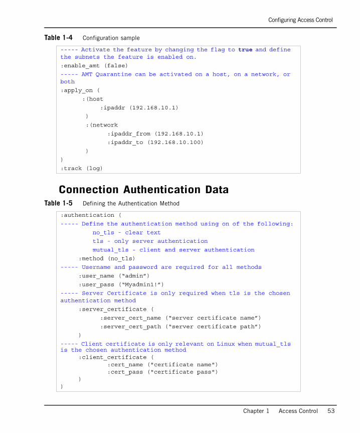
Configuring Access Control
Chapter 1 Access Control 53
Table 1-4 Configuration sample
Connection Authentication DataTable 1-5 Defining the Authentication Method
----- Activate the feature by changing the flag to true and define the subnets the feature is enabled on.
:enable_amt (false)
----- AMT Quarantine can be activated on a host, on a network, or both
:apply_on (
:(host
:ipaddr (192.168.10.1)
)
:(network
:ipaddr_from (192.168.10.1)
:ipaddr_to (192.168.10.100)
)
)
:track (log)
:authentication (
----- Define the authentication method using on of the following:
no_tls - clear text
tls - only server authentication
mutual_tls - client and server authentication
:method (no_tls)
----- Username and password are required for all methods
:user_name (“admin”)
:user_pass (“Myadmin1!”)
----- Server Certificate is only required when tls is the chosen authentication method
:server_certificate (
:server_cert_name (“server certificate name”)
:server_cert_path (“server certificate path”)
)
----- Client certificate is only relevant on Linux when mutual_tls is the chosen authentication method
:client_certificate ( :cert_name ("certificate name"):cert_pass ("certificate pass")
))
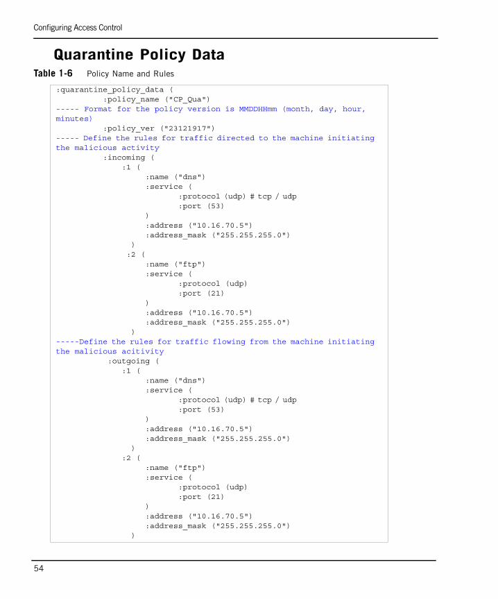
Configuring Access Control
54
Quarantine Policy DataTable 1-6 Policy Name and Rules
:quarantine_policy_data ( :policy_name ("CP_Qua")
----- Format for the policy version is MMDDHHmm (month, day, hour, minutes)
:policy_ver ("23121917")----- Define the rules for traffic directed to the machine initiating the malicious activity
:incoming ( :1 (
:name ("dns") :service (
:protocol (udp) # tcp / udp :port (53)
):address ("10.16.70.5") :address_mask ("255.255.255.0")
) :2 (
:name ("ftp") :service (
:protocol (udp) :port (21)
):address ("10.16.70.5") :address_mask ("255.255.255.0")
)-----Define the rules for traffic flowing from the machine initiating the malicious acitivity
:outgoing ( :1 (
:name ("dns") :service (
:protocol (udp) # tcp / udp :port (53)
):address ("10.16.70.5") :address_mask ("255.255.255.0")
) :2 (
:name ("ftp") :service (
:protocol (udp) :port (21)
):address ("10.16.70.5") :address_mask ("255.255.255.0")
)

Configuring Access Control
Chapter 1 Access Control 55
You can configure up to 29 rules for incoming traffic and up to 29 rules outgoing traffic.
The policy name must begin with “CP_” and cannot exceed six letters. Numbers and other characters are not permitted.
Encrypting the PasswordAfter the AMT.conf file is configured and saved, run the following command:
epq -o set_password
This command will not change the password but will encrypt the password so it is not in the clear. Running this command a second time however, will change the password. It is recommended to save and store your password in a safe place since there is no undo option.
Malicious Activity Script and AlertThe sam_alert tool executes FW-1 SAM actions according to information received through Standard input (the log mechanism). This tool is to be used for executing FW-1 SAMv2 actions with the user defined alerts mechanism.
Usagesam_alert [-O] [-S] [-t timeout] [-f target] [-n name] -[c comment] [-o originator] [-l r|a] -a d|r|n|b|q|i [-C] -ip -eth -src -dst -srv -any
Table 1-7 describes the arguments for this command.
Note - It is recommended not to change the default policy name.
Table 1-7
Argument Description
-O print the input of this tool to Standard output (for pipes).
-S Match the SAM server to be contacted. Default is localhost.
-t timeout The time period (in seconds) for which the action will be enforced. The default is forever.
-f target The firewalls on which to run the operation. Default is All.
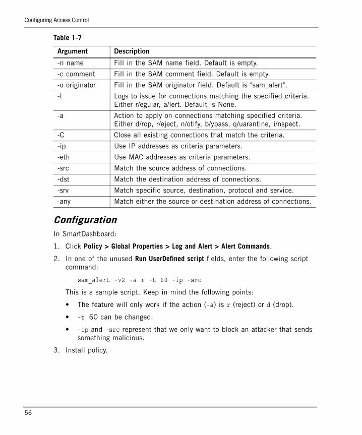
Configuring Access Control
56
ConfigurationIn SmartDashboard:
1. Click Policy > Global Properties > Log and Alert > Alert Commands.
2. In one of the unused Run UserDefined script fields, enter the following script command:
sam_alert -v2 -a r -t 60 -ip -src
This is a sample script. Keep in mind the following points:
• The feature will only work if the action (-a) is r (reject) or d (drop).
• -t 60 can be changed.
• -ip and -src represent that we only want to block an attacker that sends something malicious.
3. Install policy.
-n name Fill in the SAM name field. Default is empty.
-c comment Fill in the SAM comment field. Default is empty.
-o originator Fill in the SAM originator field. Default is "sam_alert".
-l Logs to issue for connections matching the specified criteria. Either r/egular, a/lert. Default is None.
-a Action to apply on connections matching specified criteria. Either d/rop, r/eject, n/otify, b/ypass, q/uarantine, i/nspect.
-C Close all existing connections that match the criteria.
-ip Use IP addresses as criteria parameters.
-eth Use MAC addresses as criteria parameters.
-src Match the source address of connections.
-dst Match the destination address of connections.
-srv Match specific source, destination, protocol and service.
-any Match either the source or destination address of connections.
Table 1-7
Argument Description

Configuring Access Control
Chapter 1 Access Control 57
Logging ActivityThe script is run when a malicious action is logged.
The log as it appears in SmartView Tracker.
The first log entry represents that the end point host, Broadwater, has been quarantined The second log represents that the end point host, broadwater, has been released from quarantine and authorized to be part of the network.
To Quarantine a Machine ManuallyA machine can be quarantined manually using the following command:
epq -o < status | list | is_amt | enable | disable [-l lastPolicyHandle] > -i AMTdeviceIP [policyFileName]
Table 1-8 describes the arguments for this command.
Note - Actions are not logged by default. The User Defined alert must be enabled for each threat for the sam_alert script to be activated.
Table 1-8
Argument Description
status Display the status of the policies and rules.
list List the quarantined end-point computers.
is_amt Allows the user to check if there is AMT on the machine.
enable Activates the policy.
disable Deactivates the policy being enforced.
-l lastPolicyHandle This is the last known policy to be activated.
-i AMTdeviceIP The IP address of the end-point computer you want to quarantine.
policyFileName The file name of the file containing the policy you want to enforce. (default location is $FWD-IR/conf/AMT.conf)

Configuring Access Control
58
32
Chapter 2Authentication
In This Chapter
The Need for Authentication page 33
The VPN-1 Solution for Authentication page 34
Configuring Authentication page 46
The Need for Authentication
33
The Need for AuthenticationAuthentication confirms the identity of valid users authorized to access your company network. Staff from different departments are assigned access permissions based on their level of responsibility and role within the organization. Authentication ensures that all users trying to access the system are valid users, but does not define their access rights.

The VPN-1 Solution for Authentication
Chapter 2 Authentication 34
The VPN-1 Solution for AuthenticationIn This Section
Introduction to VPN-1 AuthenticationVPN-1 authenticates individual users using credentials and manages them using different authentication schemes. All of the authentication schemes require the provision of a username and password. While some schemes involve storing the passwords on the VPN-1 gateway, others are stored on external servers.
There are three ways to access a network resource and authenticate using VPN-1:
User Authentication: Enables administrators to permit users who have temporarily left their desk to work on the local network without extending access to all users on the same host. User authentication is available only for the Telnet, FTP, HTTP and RLOGIN services.
Session Authentication: Provides an authentication mechanism for any service and requires users to supply their credentials for each authentication session. A session authentication agent must be installed on every authenticating client, therefore this method is not suitable for authenticating HTTP services as they open multiple connections per session. Similar to client authentication, it is best used on single user machines, where only one user can authenticate from a given IP at any one time.
Client Authentication: Permits multiple users and connections from the authorized IP address or host. Authorization is performed per machine. For example, if FINGER is authorized for a client machine, then all users on the client are authorized to use FINGER and are not asked to supply a password during the authorization process. Client authentication is best enabled on single-user machines.
The main advantage of client authentication is that it can be used on any number of connections for any service and authentication can be set to valid for a specified time period.
These authentication methods can also be used for unencrypted communication.
Introduction to VPN-1 Authentication page 34
Authentication Schemes page 35
Authentication Methods page 37
The VPN-1 Solution for Authentication
35
Authentication is required for Remote Access communication using SecuRemote/SecureClient.
Authentication SchemesAuthentication schemes employ usernames and passwords to identify valid users. Some schemes are maintained locally and store usernames and passwords on the VPN-1 gateway, while others are maintained externally and store user authentication information on an external authentication server. Certain schemes, such as SecurID, are based on providing a one-time password. All of the schemes can be used with users defined on an LDAP server. For additional information on configuring VPN-1 to integrate with an LDAP server, refer to the SmartDirectory (LDAP) and User Management section in the SmartCenter Administration Guide.
Check Point PasswordVPN-1 can store a static password in the local user database of each user configured in SmartCenter server. No additional software is required.
Operating System PasswordVPN-1 can authenticate using the username and password that is stored on the operating system of the machine on which VPN-1 is installed. You can also use passwords that are stored in a Windows domain. No additional software is required.
RADIUSRemote Authentication Dial-In User Service (RADIUS) is an external authentication scheme that provides security and scalability by separating the authentication function from the access server.
Using RADIUS, VPN-1 forwards authentication requests by remote users to the RADIUS server. The RADIUS server, which stores user account information, authenticates the users.
The RADIUS protocol uses UDP to communicate with the gateway. RADIUS servers and RADIUS server group objects are defined in SmartDashboard. For additional information on configuring RADIUS, refer to “Configuring a VPN-1 Gateway to use RADIUS” on page 60.
The VPN-1 Solution for Authentication
Chapter 2 Authentication 36
SecurIDSecurID requires users to both possess a token authenticator and to supply a PIN or password. Token authenticators generate one-time passwords that are synchronized to an RSA ACE/server and may come in the form of hardware or software. Hardware tokens are key-ring or credit card-sized devices, while software tokens reside on the PC or device from which the user wants to authenticate. All tokens generate a random, one-time use access code that changes approximately every minute. When a user attempts to authenticate to a protected resource, the one-time use code must be validated by the ACE/server.
Using SecurID, VPN-1 forwards authentication requests by remote users to the ACE/server. ACE manages the database of RSA users and their assigned hard or soft tokens. The VPN-1 gateway acts as an ACE/Agent 5.0 and directs all access requests to the RSA ACE/server for authentication. For additional information on agent configuration, refer to ACE/server documentation.
There are no specific parameters required for the SecurID authentication scheme. For additional information on configuring SecurID, refer to “Configuring a VPN-1 Gateway to use SecurID” on page 66.
TACACSTerminal Access Controller Access Control System (TACACS) provides access control for routers, network access servers and other networked devices through one or more centralized servers.
TACACS is an external authentication scheme that provides verification services. Using TACACS, VPN-1 forwards authentication requests by remote users to the TACACS server. The TACACS server, which stores user account information, authenticates users. The system supports physical card key devices or token cards and Kerberos secret key authentication. TACACS encrypts the username, password, authentication services and accounting information of all authentication requests to ensure secure communication.
For additional information on configuring TACACS, refer to: “Configuring a VPN-1 Gateway to use TACACS+” on page 68.
UndefinedThe authentication scheme for a user can be defined as undefined. If a user with an undefined authentication scheme is matched to a Security Rule with some form of authentication, access is always denied.
The VPN-1 Solution for Authentication
37
Authentication Methods
In This Section
Introduction to Authentication MethodsInstead of creating a security rule that simply allows or denies connections, the firewall administrator can request that clients authenticate when they try to access specific network resources.
There are three authentication methods available: user, client and session (for additional information, refer to “Introduction to Authentication Methods” on page 37). These methods differ in the services provided, the logon mechanism, and the overall user experience. Each method can be configured to connect and authenticate clients to the VPN-1 gateway before the connection is passed to the desired resource (a process known as nontransparent authentication). Alternatively, each method can be configured to connect clients directly to the target server (a process known as transparent authentication).
This section describes how users authenticate using each authentication method. For additional information on configuring authentication methods, refer to “Configuring Authentication” on page 46.
User AuthenticationUser Authentication provides authentication for the Telnet, FTP, HTTP, and rlogin services. By default, User Authentication is transparent. The user does not connect directly to the VPN-1 gateway, but initiates a connection to the target server.
The following is a typical User Authentication method workflow:
1. VPN-1 intercepts the communication between the client and server.
2. VPN-1 prompts the user for a username and password.
3. If the user successfully authenticates, VPN-1 passes the connection to the remote host. If incorrect authentication information is provided during the allowed number of connection attempts, the connection is dropped.
Introduction to Authentication Methods page 37
User Authentication page 37
Session Authentication page 40
Client Authentication page 41
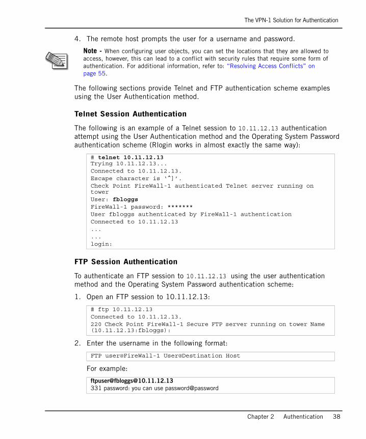
The VPN-1 Solution for Authentication
Chapter 2 Authentication 38
4. The remote host prompts the user for a username and password.
The following sections provide Telnet and FTP authentication scheme examples using the User Authentication method.
Telnet Session Authentication
The following is an example of a Telnet session to 10.11.12.13 authentication attempt using the User Authentication method and the Operating System Password authentication scheme (Rlogin works in almost exactly the same way):
FTP Session Authentication
To authenticate an FTP session to 10.11.12.13 using the user authentication method and the Operating System Password authentication scheme:
1. Open an FTP session to 10.11.12.13:
2. Enter the username in the following format:
For example:
Note - When configuring user objects, you can set the locations that they are allowed to access, however, this can lead to a conflict with security rules that require some form of authentication. For additional information, refer to: “Resolving Access Conflicts” on page 55.
# telnet 10.11.12.13Trying 10.11.12.13...Connected to 10.11.12.13.Escape character is ‘^]’.Check Point FireWall-1 authenticated Telnet server running on towerUser: fbloggsFireWall-1 password: *******User fbloggs authenticated by FireWall-1 authenticationConnected to 10.11.12.13......login:
# ftp 10.11.12.13Connected to 10.11.12.13.220 Check Point FireWall-1 Secure FTP server running on tower Name (10.11.12.13:fbloggs):
FTP user@FireWall-1 User@Destination Host
ftpuser@[email protected]
331 password: you can use password@password
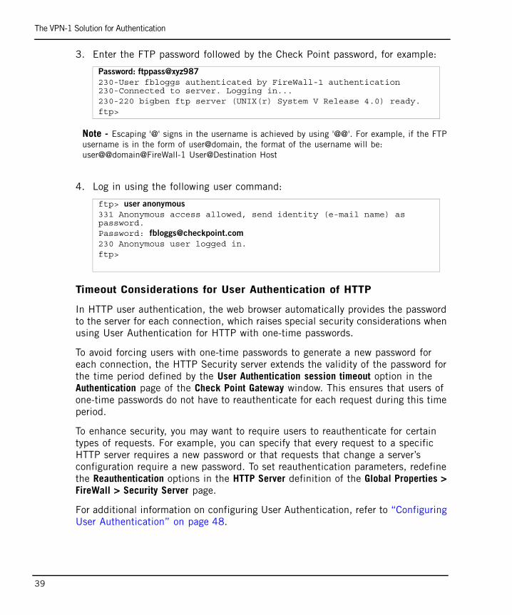
The VPN-1 Solution for Authentication
39
3. Enter the FTP password followed by the Check Point password, for example:
Note - Escaping '@' signs in the username is achieved by using '@@'. For example, if the FTP username is in the form of user@domain, the format of the username will be:user@@domain@FireWall-1 User@Destination Host
4. Log in using the following user command:
Timeout Considerations for User Authentication of HTTP
In HTTP user authentication, the web browser automatically provides the password to the server for each connection, which raises special security considerations when using User Authentication for HTTP with one-time passwords.
To avoid forcing users with one-time passwords to generate a new password for each connection, the HTTP Security server extends the validity of the password for the time period defined by the User Authentication session timeout option in the Authentication page of the Check Point Gateway window. This ensures that users of one-time passwords do not have to reauthenticate for each request during this time period.
To enhance security, you may want to require users to reauthenticate for certain types of requests. For example, you can specify that every request to a specific HTTP server requires a new password or that requests that change a server’s configuration require a new password. To set reauthentication parameters, redefine the Reauthentication options in the HTTP Server definition of the Global Properties > FireWall > Security Server page.
For additional information on configuring User Authentication, refer to “Configuring User Authentication” on page 48.
Password: ftppass@xyz987
230-User fbloggs authenticated by FireWall-1 authentication 230-Connected to server. Logging in...230-220 bigben ftp server (UNIX(r) System V Release 4.0) ready.ftp>
ftp> user anonymous
331 Anonymous access allowed, send identity (e-mail name) as password.Password: [email protected]
230 Anonymous user logged in.ftp>
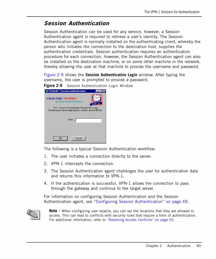
The VPN-1 Solution for Authentication
Chapter 2 Authentication 40
Session AuthenticationSession Authentication can be used for any service, however, a Session Authentication agent is required to retrieve a user’s identity. The Session Authentication agent is normally installed on the authenticating client, whereby the person who initiates the connection to the destination host, supplies the authentication credentials. Session authentication requires an authentication procedure for each connection, however, the Session Authentication agent can also be installed on the destination machine, or on some other machine in the network, thereby allowing the user at that machine to provide the username and password.
Figure 2-9 shows the Session Authentication Login window. After typing the username, the user is prompted to provide a password. Figure 2-9 Session Authentication Login Window
The following is a typical Session Authentication workflow:
1. The user initiates a connection directly to the server.
2. VPN-1 intercepts the connection.
3. The Session Authentication agent challenges the user for authentication data and returns this information to VPN-1.
4. If the authentication is successful, VPN-1 allows the connection to pass through the gateway and continue to the target server.
For information on configuring Session Authentication and the Session Authentication agent, see “Configuring Session Authentication” on page 49.
Note - When configuring user objects, you can set the locations that they are allowed to access. This can lead to conflicts with security rules that require a form of authentication. For additional information, refer to “Resolving Access Conflicts” on page 55.
The VPN-1 Solution for Authentication
41
Client Authentication
In This Section
Client Authentication and Sign On Overview
Client Authentication can be used to authenticate any service. It enables access from a specific IP address for an unlimited number of connections. The client user performs the authentication process, but it is the client machine that is granted access. Client Authentication is less secure than user authentication because it permits access for multiple users and connections from authorized IP addresses or hosts. Authorization is performed on a per machine basis for services that do not have an initial login procedure. The advantages of Client Authentication are that it can be used for an unlimited number of connections, for any service, and is valid for any length of time.
Client Authentication and Sign On Overview page 41
Manual Sign On page 42
Wait Mode page 44
Partially Automatic Sign On page 44
Fully Automatic Sign On page 44
Agent Automatic Sign On page 45
Single Sign On page 45
Note - When configuring user objects, you can set the locations that users can access, however, this can cause problems with security rules that require some form of authentication. For additional information, refer to “Resolving Access Conflicts” on page 55.
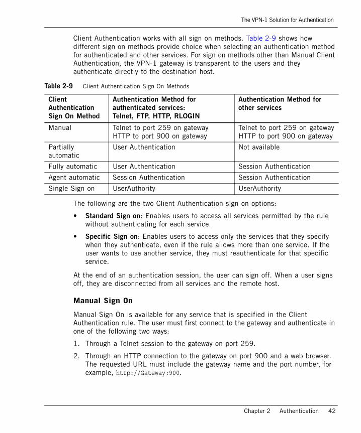
The VPN-1 Solution for Authentication
Chapter 2 Authentication 42
Client Authentication works with all sign on methods. Table 2-9 shows how different sign on methods provide choice when selecting an authentication method for authenticated and other services. For sign on methods other than Manual Client Authentication, the VPN-1 gateway is transparent to the users and they authenticate directly to the destination host.
The following are the two Client Authentication sign on options:
• Standard Sign on: Enables users to access all services permitted by the rule without authenticating for each service.
• Specific Sign on: Enables users to access only the services that they specify when they authenticate, even if the rule allows more than one service. If the user wants to use another service, they must reauthenticate for that specific service.
At the end of an authentication session, the user can sign off. When a user signs off, they are disconnected from all services and the remote host.
Manual Sign On
Manual Sign On is available for any service that is specified in the Client Authentication rule. The user must first connect to the gateway and authenticate in one of the following two ways:
1. Through a Telnet session to the gateway on port 259.
2. Through an HTTP connection to the gateway on port 900 and a web browser. The requested URL must include the gateway name and the port number, for example, http://Gateway:900.
Table 2-9 Client Authentication Sign On Methods
Client
Authentication
Sign On Method
Authentication Method for
authenticated services:
Telnet, FTP, HTTP, RLOGIN
Authentication Method for
other services
Manual Telnet to port 259 on gatewayHTTP to port 900 on gateway
Telnet to port 259 on gatewayHTTP to port 900 on gateway
Partially automatic
User Authentication Not available
Fully automatic User Authentication Session Authentication
Agent automatic Session Authentication Session Authentication
Single Sign on UserAuthority UserAuthority

The VPN-1 Solution for Authentication
43
The following example shows Client Authentication using a Standard Manual Sign On method. In this example, before opening a connection to the destination host, the user fbloggs first authenticates to london, the VPN-1 gateway:
The following example shows Client Authentication using a Specific Manual Sign On method. In this example, two services are specified: rstat and finger (each one to a different host).
tower 1% telnet london 259Trying 191.23.45.67 ...Connected to london.Escape character is '^]'.CheckPoint FireWall-1 Client Authentication Server running on londonLogin: fbloggsFireWall-1 Password: ********User authenticated by FireWall-1 auth.
Choose:(1) Standard Sign On(2) Sign Off(3) Specific Sign On
Enter your choice: 1
User authorized for standard services (1 rules)Connection closed by foreign host.
tower 3% telnet london 259Trying 191.23.45.67 ...Connected to london.Escape character is '^]'.CheckPoint FireWall-1 Client Authentication Server running on londonLogin: jimFireWall-1 Password: ********User authenticated by Internal auth.
Choose:(1) Standard Sign On(2) Sign Off(3) Specific Sign On
Enter your choice: 3Service: rstatHost: palaceClient Authorized for serviceAnother one (Y/N): YService: fingerHost: thamesClient Authorized for serviceAnother one (Y/N): nConnection closed by foreign host.
The VPN-1 Solution for Authentication
Chapter 2 Authentication 44
Wait Mode
Wait mode is a Client Authentication feature for Manual Sign On when the user initiates a client authenticated connection with a Telnet session on port 259 on the gateway.
Wait mode eliminates the need to open a new Telnet session in order to sign off and withdraw client authentication privileges. In Wait mode, the initial Telnet session connection remains open so long as client authentication privileges remain valid. Client authentication privileges are withdrawn when the Telnet session is closed.
VPN-1 keeps the Telnet session open by pinging the authenticating client. If for some reason the client machine stops running, VPN-1 closes the Telnet session and client authentication privileges from the connected IP address are withdrawn.
Enable Wait mode works only with client authentication rules that specify Standard Sign On. In Enable Wait mode, client authentication rules that require Specific Sign On are not applied.
Partially Automatic Sign On
Partially Automatic Sign On is available for authenticated services (Telnet, FTP, HTTP and RLOGIN) only if they are specified in the client authentication rule. If the user attempts to connect to a remote host using one of the authenticated services, they must authenticate with User Authentication. When using Partially Automatic Client Authentication, ensure that port 80 is accessible on the gateway machine.
Fully Automatic Sign On
Fully Automatic Sign On is available for any service only if the required service is specified in the client authentication rule. If the user attempts to connect to a remote host using an authenticated service (Telnet, FTP, HTTP, and RLOGIN), they must authenticate with User Authentication. If the user attempts to connect to a remote host using any other service, they must authenticate through a properly installed Session Authentication agent. When using Fully Automatic Client Authentication, ensure that port 80 is accessible on the gateway machine.

The VPN-1 Solution for Authentication
45
Agent Automatic Sign On
Agent Automatic Sign On is available only if the required service is specified in the Client Authentication rule, and the Session Authentication agent is properly installed.
If a user attempts to connect to a remote host using any service, they must authenticate through a Session Authentication agent.
Single Sign On
Single Sign On is available for any service only if the required service is specified in the Client Authentication rule and UserAuthority is installed.
Single Sign On is a Check Point address management feature that provides transparent network access. VPN-1 consults the user IP address records to determine which users are logged on to any given IP address. When a connection matches a Single Sign On enabled rule, VPN-1 queries UserAuthority with the packet's source IP. UserAuthority returns the name of the user who is registered to the IP. If the user's name is authenticated, the packet is accepted, if not, it is dropped.
Configuring Authentication
Chapter 2 Authentication 46
Configuring AuthenticationIn This Section
Creating Users and GroupsAuthentication rules are defined by user groups rather than individual users. Therefore, you must first define users and then add them to groups in order to define authentication rules. You can define users using the VPN-1 proprietary user database or using an LDAP server. For details on incorporating LDAP, refer to SmartDirectory (LDAP) and User Management in the SmartCenter Administration Guide.
The following procedure describes how to create a group, create VPN-1 users using a template, add users to the group and install user information in the database. For additional information on creating users and groups, refer to the SmartCenter Overview in the SmartCenter Administration Guide.
Creating User GroupsTo create a user group:
1. Select User Groups from the Users and Administrators tab of the Objects tree.
2. Right-click and select New Group.... The Group Properties window opens.
3. Assign the group a Name.
4. To add users to the group, refer to “Creating Users” on page 47.
Creating Users and Groups page 46
Configuring User Authentication page 48
Configuring Session Authentication page 49
Configuring Client Authentication page 54
Configuring Authentication Tracking page 60
Configuring a VPN-1 Gateway to use RADIUS page 60
Granting User Access Using RADIUS Server Groups page 63
Associating a RADIUS Server with a VPN-1 Gateway page 65
Configuring a VPN-1 Gateway to use SecurID page 66
Configuring a VPN-1 Gateway to use TACACS+ page 68
Configuring Policy for Groups of Windows Users page 69

Configuring Authentication
47
Creating a User TemplateTo create a user template:
1. Select the Users from the Users and Administrators tab of the Objects tree.
2. In the Templates branch, right-click and select New Template.... The User Template Properties window opens.
3. Assign the template a name.
4. In the Groups tab, add the user template to all of the groups to which users based on this template must belong.
5. In the Authentication tab, select the appropriate authentication scheme for the user.
6. In the remaining tabs, enter the required properties of the user template.
Once you create a template, any user that you create based on a given template inherits that template’s properties, including membership in groups. If you modify a template’s properties, those changes will only affect future users created using that template. Users previously created using that template are not affected.
Creating UsersTo create users:
1. In the Users branch of the objects tree, right-click and select the template on which the new user’s properties are to be based. The User Properties window opens.
2. Enter the user data. You can change the properties that the user inherited from the template for that user only without changing the template.
Installing User Information in the DatabaseUsers and groups can be installed separately from the Rule Base, meaning that you can update users and groups without reinstalling the Rule Base.
To install the user database:
• From the SmartDashboard menu, select Policy > Install Database....
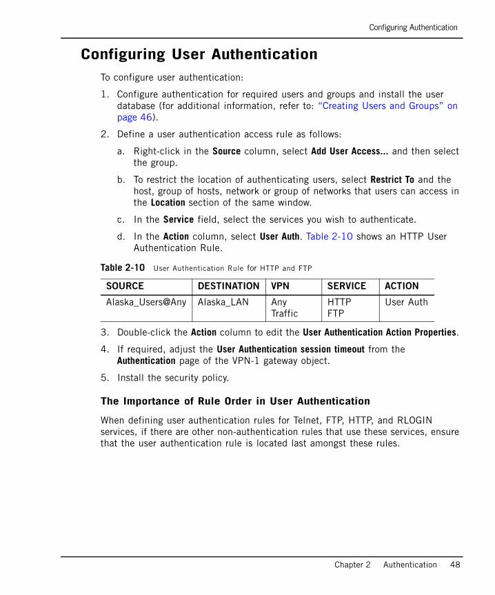
Configuring Authentication
Chapter 2 Authentication 48
Configuring User AuthenticationTo configure user authentication:
1. Configure authentication for required users and groups and install the user database (for additional information, refer to: “Creating Users and Groups” on page 46).
2. Define a user authentication access rule as follows:
a. Right-click in the Source column, select Add User Access... and then select the group.
b. To restrict the location of authenticating users, select Restrict To and the host, group of hosts, network or group of networks that users can access in the Location section of the same window.
c. In the Service field, select the services you wish to authenticate.
d. In the Action column, select User Auth. Table 2-10 shows an HTTP User Authentication Rule.
3. Double-click the Action column to edit the User Authentication Action Properties.
4. If required, adjust the User Authentication session timeout from the Authentication page of the VPN-1 gateway object.
5. Install the security policy.
The Importance of Rule Order in User Authentication
When defining user authentication rules for Telnet, FTP, HTTP, and RLOGIN services, if there are other non-authentication rules that use these services, ensure that the user authentication rule is located last amongst these rules.
Table 2-10 User Authentication Rule for HTTP and FTP
SOURCE DESTINATION VPN SERVICE ACTION
Alaska_Users@Any Alaska_LAN Any Traffic
HTTPFTP
User Auth
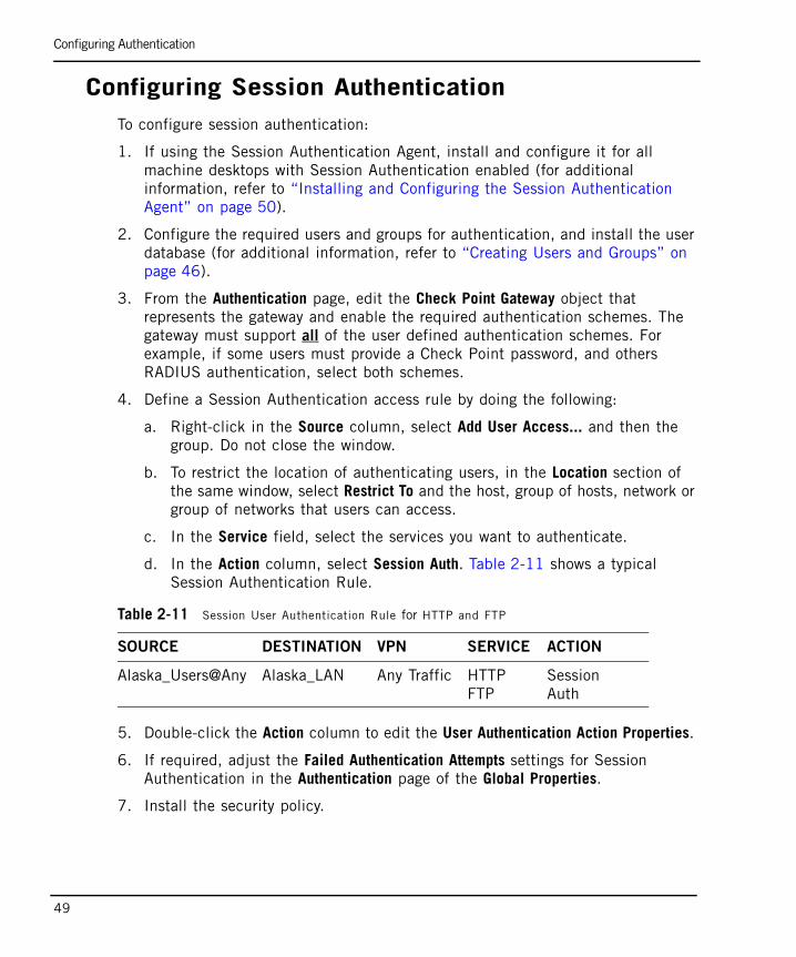
Configuring Authentication
49
Configuring Session AuthenticationTo configure session authentication:
1. If using the Session Authentication Agent, install and configure it for all machine desktops with Session Authentication enabled (for additional information, refer to “Installing and Configuring the Session Authentication Agent” on page 50).
2. Configure the required users and groups for authentication, and install the user database (for additional information, refer to “Creating Users and Groups” on page 46).
3. From the Authentication page, edit the Check Point Gateway object that represents the gateway and enable the required authentication schemes. The gateway must support all of the user defined authentication schemes. For example, if some users must provide a Check Point password, and others RADIUS authentication, select both schemes.
4. Define a Session Authentication access rule by doing the following:
a. Right-click in the Source column, select Add User Access... and then the group. Do not close the window.
b. To restrict the location of authenticating users, in the Location section of the same window, select Restrict To and the host, group of hosts, network or group of networks that users can access.
c. In the Service field, select the services you want to authenticate.
d. In the Action column, select Session Auth. Table 2-11 shows a typical Session Authentication Rule.
5. Double-click the Action column to edit the User Authentication Action Properties.
6. If required, adjust the Failed Authentication Attempts settings for Session Authentication in the Authentication page of the Global Properties.
7. Install the security policy.
Table 2-11 Session User Authentication Rule for HTTP and FTP
SOURCE DESTINATION VPN SERVICE ACTION
Alaska_Users@Any Alaska_LAN Any Traffic HTTPFTP
Session Auth
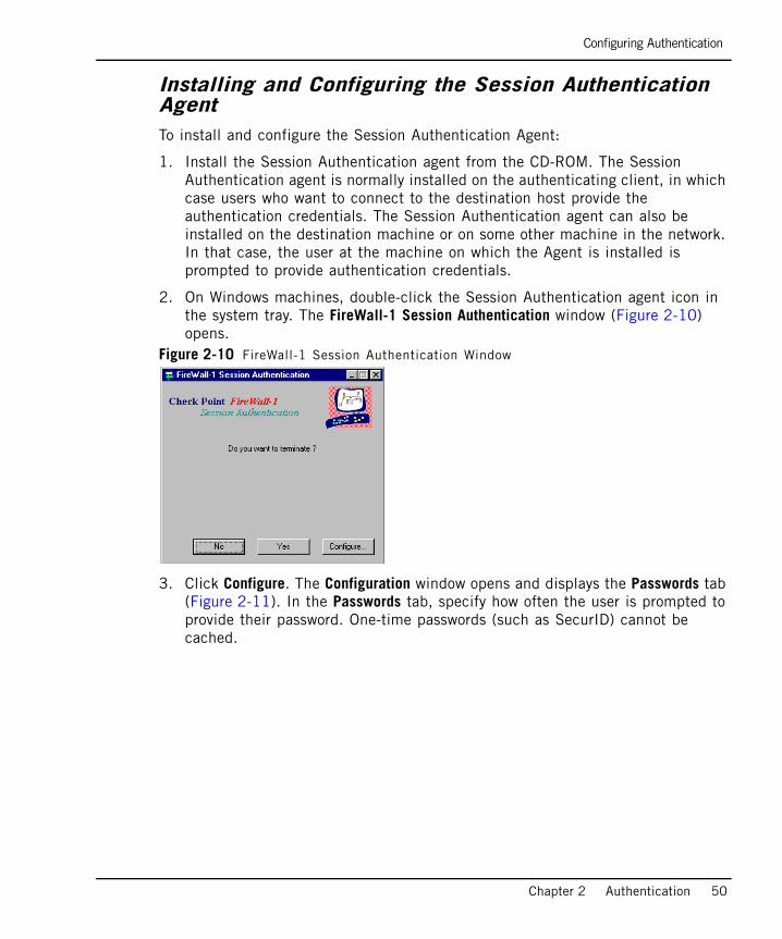
Configuring Authentication
Chapter 2 Authentication 50
Installing and Configuring the Session Authentication AgentTo install and configure the Session Authentication Agent:
1. Install the Session Authentication agent from the CD-ROM. The Session Authentication agent is normally installed on the authenticating client, in which case users who want to connect to the destination host provide the authentication credentials. The Session Authentication agent can also be installed on the destination machine or on some other machine in the network. In that case, the user at the machine on which the Agent is installed is prompted to provide authentication credentials.
2. On Windows machines, double-click the Session Authentication agent icon in the system tray. The FireWall-1 Session Authentication window (Figure 2-10) opens.
Figure 2-10 FireWall-1 Session Authentication Window
3. Click Configure. The Configuration window opens and displays the Passwords tab (Figure 2-11). In the Passwords tab, specify how often the user is prompted to provide their password. One-time passwords (such as SecurID) cannot be cached.
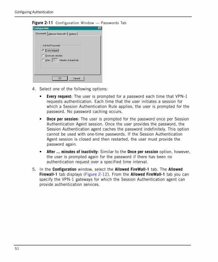
Configuring Authentication
51
Figure 2-11 Configuration Window — Passwords Tab
4. Select one of the following options:
• Every request: The user is prompted for a password each time that VPN-1 requests authentication. Each time that the user initiates a session for which a Session Authentication Rule applies, the user is prompted for the password. No password caching occurs.
• Once per session: The user is prompted for the password once per Session Authentication Agent session. Once the user provides the password, the Session Authentication agent caches the password indefinitely. This option cannot be used with one-time passwords. If the Session Authentication Agent session is closed and then restarted, the user must provide the password again.
• After ... minutes of inactivity: Similar to the Once per session option, however, the user is prompted again for the password if there has been no authentication request over a specified time interval.
5. In the Configuration window, select the Allowed FireWall-1 tab. The Allowed Firewall-1 tab displays (Figure 2-12). From the Allowed FireWall-1 tab you can specify the VPN-1 gateways for which the Session Authentication agent can provide authentication services.
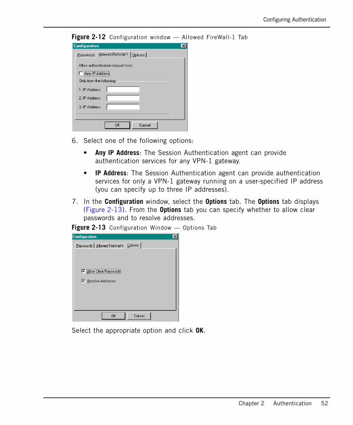
Configuring Authentication
Chapter 2 Authentication 52
Figure 2-12 Configuration window — Allowed FireWall-1 Tab
6. Select one of the following options:
• Any IP Address: The Session Authentication agent can provide authentication services for any VPN-1 gateway.
• IP Address: The Session Authentication agent can provide authentication services for only a VPN-1 gateway running on a user-specified IP address (you can specify up to three IP addresses).
7. In the Configuration window, select the Options tab. The Options tab displays (Figure 2-13). From the Options tab you can specify whether to allow clear passwords and to resolve addresses.
Figure 2-13 Configuration Window — Options Tab
Select the appropriate option and click OK.

Configuring Authentication
53
Starting the Session Authentication AgentTo start the Session Authentication Agent:
• From the Windows system tray, select the minimized Session Authentication Agent icon. The user can now configure the Session Authentication Agent and/or receive authentication requests from a VPN-1 gateway.
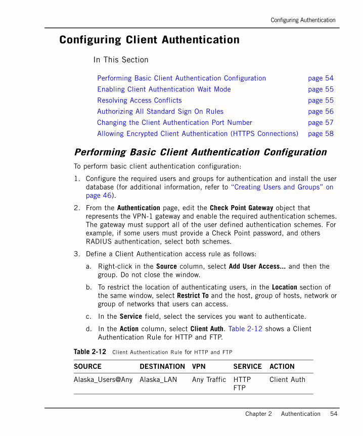
Configuring Authentication
Chapter 2 Authentication 54
Configuring Client Authentication
In This Section
Performing Basic Client Authentication ConfigurationTo perform basic client authentication configuration:
1. Configure the required users and groups for authentication and install the user database (for additional information, refer to “Creating Users and Groups” on page 46).
2. From the Authentication page, edit the Check Point Gateway object that represents the VPN-1 gateway and enable the required authentication schemes. The gateway must support all of the user defined authentication schemes. For example, if some users must provide a Check Point password, and others RADIUS authentication, select both schemes.
3. Define a Client Authentication access rule as follows:
a. Right-click in the Source column, select Add User Access... and then the group. Do not close the window.
b. To restrict the location of authenticating users, in the Location section of the same window, select Restrict To and the host, group of hosts, network or group of networks that users can access.
c. In the Service field, select the services you want to authenticate.
d. In the Action column, select Client Auth. Table 2-12 shows a Client Authentication Rule for HTTP and FTP.
Performing Basic Client Authentication Configuration page 54
Enabling Client Authentication Wait Mode page 55
Resolving Access Conflicts page 55
Authorizing All Standard Sign On Rules page 56
Changing the Client Authentication Port Number page 57
Allowing Encrypted Client Authentication (HTTPS Connections) page 58
Table 2-12 Client Authentication Rule for HTTP and FTP
SOURCE DESTINATION VPN SERVICE ACTION
Alaska_Users@Any Alaska_LAN Any Traffic HTTPFTP
Client Auth
Configuring Authentication
55
4. For Partially or Fully Automatic Client Authentication, ensure that port 80 is accessible on the gateway machine.
5. Double-click in the Action column to edit the Client Authentication Action Properties. The settings for Requires Sign On and Sign On Method are described in “Client Authentication” on page 41.
6. Place all Client Authentication Rules above the rule that prevents direct connections to the VPN-1 gateway (the Stealth Rule) to ensure that they have access to the VPN-1 gateway.
7. If required, adjust the Failed Authentication Attempts settings for Client Authentication in the Authentication page of the Global Properties window.
8. Install the security policy.
Enabling Client Authentication Wait ModeWhen using Manual Sign On and the user authenticates with a Telnet session to port 259 on the gateway, Wait mode eliminates the need to open a new Telnet session in order to sign off and withdraw client authentication privileges.
To enable Wait mode:
1. From the Authentication page, edit the Check Point Gateway object that represents the VPN-1 gateway and select Enable Wait Mode for Client Authentication. In Client Authentication Wait mode, VPN-1 monitors the Telnet connection to port 259 of the gateway by pinging the user’s host.
2. Define rules to enable pinging as follows:
• Enable the echo-request service from the VPN-1 gateway to the user’s host.
• Enable the echo-reply service from the user’s host to the VPN-1 gateway.
Resolving Access Conflicts When configuring users, you can define those locations that they can access. However, by doing so, you disallow access to all unspecified locations, which can cause conflicts with security rules that require authentication. For example, if a rule grants authenticated access to users from Mktg_net to Finance_net, but in the user’s Location tab connections are only permitted within Mktg_net, VPN-1 does not know whether to allow the authentication request when the user tries to connect to Finance_net.
You can specify how to resolve this conflict by editing the Authentication Action Property of the rule. You can define this property for both the Source and Destination of the rule.

Configuring Authentication
Chapter 2 Authentication 56
To resolve access conflicts:
1. Right-click the Action field of a rule using some form of authentication and select Edit Properties.
2. Do one of the following:
• To apply the more restrictive access privileges specified in the rule and in the Location tab of each user’s User Properties window, select Intersect with User Database.
• To allow access according to the location specified in the rule, select Ignore User Database.
Authorizing All Standard Sign On RulesBy default, the Partially or Fully Automatic sign on methods open one rule following successful authentication (the rule for which the sign on was initiated). For example, if a user successfully authenticates according an automatic sign on rule, the user can work with the services and destinations permitted only by that rule.
You can configure VPN-1 to automatically open all Standard Sign On rules following successful authentication using Partially or Fully Automatic Sign On. If a user successfully authenticates according to an automatic sign on rule, then all Standard Sign On rules that define that user and source are available. The user can then work with all of the services and destinations permitted by the relevant rules (VPN-1 knows which user is at the client, and additional authentication is not necessary).
To authorize all relevant Standard Sign On Rules following successful .
Partially or Fully Automatic authentication, use the GUIdbedit Database Tool to change a setting in the VPN-1 database.
To authorize all standard sign on rules:
1. Access the GUIdbedit Database Tool from the same directory on your local drive as where SmartConsole is installed.
2. Open GUIdbedit.
3. Search for the automatically_open_ca_rules field.
4. Set the value to true. The new value takes effect after you install the security policy.
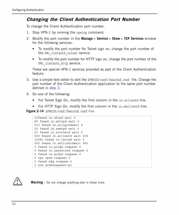
Configuring Authentication
57
Changing the Client Authentication Port NumberTo change the Client Authentication port number:
1. Stop VPN-1 by running the cpstop command.
2. Modify the port number in the Manage > Service > Show > TCP Services window for the following services:
• To modify the port number for Telnet sign on, change the port number of the FW1_clntauth_telnet service.
• To modify the port number for HTTP sign on, change the port number of the FW1_clntauth_http service.
These are special VPN-1 services provided as part of the Client Authentication feature.
3. Use a simple text editor to edit the $FWDIR/conf/fwauthd.conf file. Change the port number of the Client Authentication application to the same port number defined in step 2.
4. Do one of the following:
• For Telnet Sign On, modify the first column in the in.aclientd line.
• For HTTP Sign On, modify the first column in the in.ahclientd line. Figure 2-14 $FWDIR/conf/fwauthd.conf File
21fwssd in.aftpd wait 080 fwssd in.ahttpd wait 0513 fwssd in.arlogindwait 025 fwssd in.asmtpd wait 023 fwssd in.atelnetd wait 0259 fwssd in.aclientd wait 25910081 fwssd in.lhttpd wait 0900 fwssd in.ahclientdwait 9000 fwssd in.pingd respawn 00 fwssd in.asessiond respawn 00 fwssd in.aufpd respawn 00 vpn vpnd respawn 00 fwssd mdq respawn 00 xrm xrmdrespawn0-pr
Warning - Do not change anything else in these lines.
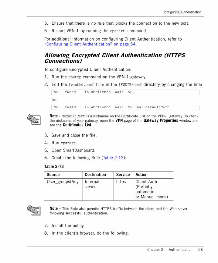
Configuring Authentication
Chapter 2 Authentication 58
5. Ensure that there is no rule that blocks the connection to the new port.
6. Restart VPN-1 by running the cpstart command.
For additional information on configuring Client Authentication, refer to “Configuring Client Authentication” on page 54.
Allowing Encrypted Client Authentication (HTTPS Connections)To configure Encrypted Client Authentication:
1. Run the cpstop command on the VPN-1 gateway.
2. Edit the fwauthd.conf file in the $FWDIR/conf directory by changing the line:
to:
3. Save and close the file.
4. Run cpstart.
5. Open SmartDashboard.
6. Create the following Rule (Table 2-13):
7. Install the policy.
8. In the client's browser, do the following:
900 fwssd in.ahclientd wait 900
900 fwssd in.ahclientd wait 900 ssl:defaultCert
Note - defaultCert is a nickname on the Certificate List on the VPN-1 gateway. To check the nickname of your gateway, open the VPN page of the Gateway Properties window and see the Certificates List.
Table 2-13
Source Destination Service Action
User_group@Any Internal server
https Client Auth(Partially automaticor Manual mode)
Note - This Rule also permits HTTPS traffic between the client and the Web server following successful authentication.
Configuring Authentication
59
a. Type the URL addresshttps://<FireWall-1_name_or_IP_address>:900.
b. Click Yes to trust the VPN-1 gateway certificate.
c. Type the VPN-1 user name.
d. Click OK.
e. Click Yes.
f. Type the VPN-1 password.
g. Click Submit.
h. Type the URL address: https://<Internal_Web_Server_IP_address>.
i. Click Yes.
You are now authenticated both to the VPN-1 gateway and to your internal Web server.
Configuring Authentication
Chapter 2 Authentication 60
Configuring Authentication TrackingSuccessful and unsuccessful authentication attempts can be monitored in SmartView Tracker or using other tracking options, for example, email and alerts. Authentication tracking can be configured for the following types of authentication attempts:
• Failed authentication attempts: Can be tracked for all forms of authentication.
To track failed authentication attempts:
• In the Authentication page of a gateway object, set the Authentication Failure Track property to define the tracking option when authentication failures occur.
• Successful authentication attempts: Can be tracked for Client Authentication.
To track successful authentication attempts:
1. In the Client Authentication Action Properties window, set the Successful Authentication Tracking property to define the tracking option for all successful Client Authentication attempts.
2. To set this option, right-click in the Action column of the Client Authentication rule. The default setting is Log.
• All Authentication attempts: Can be tracked for all forms of authentication.
To track all authentication attempts:
• Select an option in the Track column of any rule that uses some form of authentication. The Set by Rule tracking option can only be added to the tracking policy set in the gateway object. For example, if the gateway object is set to log all failed authentication attempts, setting a rule to None has no effect and failed authentication attempts are still logged in SmartView Tracker. However, setting the rule to Alert causes an Alert to be sent for each failed authentication attempt.
Configuring a VPN-1 Gateway to use RADIUSTo configure a VPN-1 gateway to use RADIUS authentication:
1. In SmartDashboard, create a RADIUS Host object by selecting Manage > Network Objects > New > Node > Host....
Note - Authentication failure tracking for Check Point firewall versions prior to NG is defined by the Authentication Failure Track property in the Authentication page of the Global Properties window.

Configuring Authentication
61
2. Name the Host object and assign it an IP address.
3. Create a RADIUS Server object by selecting Manage > Server and OPSEC Applications > New…> RADIUS…, and configure the following:
a. Name the RADIUS Server object.
b. Associate the RADIUS Server object with the RADIUS Host object created in step 1.
c. Assign the Service by selecting either the RADIUS on port 1645 or NEW-RADIUS on port 1812 service. (The default setting is RADIUS, however the RADIUS standards group recommends using NEW-RADIUS, because port 1645 can conflict with the datametrics service running on the same port.)
d. Assign the same Shared Secret that you configured on the actual RADIUS server.
e. Select either RADIUS Ver. 1.0 Compatible, which is RFC 2138 compliant, or RADIUS Ver. 2.0 Compatible, which is RFC 2865 compliant.
f. Assign the RADIUS server’s Priority if you are employing more than one RADIUS Authentication server.
g. Click OK.
4. Right-click the gateway object and select Edit > Authentication.
5. Enable RADIUS authentication.
6. Define a user group by selecting Manage > Users & Administrators > New > User Group (for example, RADIUS_Users).
7. Enable RADIUS authentication for VPN-1 users by selecting Manage > Users and Administrators > New > User by Template > Default..
8. Enable RADIUS authentication for users without VPN-1 user accounts by creating an External User Profile. Select Manage > Users and Administrators > New > External User Profile > Match all users... or Match by domain.... To support more than one external authentication scheme, define your External User Profiles with the Match By Domain setting.
9. For all User Profiles and Templates, configure the following:
a. In the General tab, type the default login name for the RADIUS server. (When configuring Match all users as an External User Profile, the name “generic*” is automatically assigned.)
b. In the Personal tab, adjust the Expiration Date.
c. In the Authentication tab, select RADIUS from the drop-down list.
Configuring Authentication
Chapter 2 Authentication 62
d. In the Groups tab, add the User Profile to the RADIUS group.
10. Verify that communication between the firewall and the RADIUS server are not NATed in the Address Translation Rule Base.
11. Save, verify, and install the policy.

Configuring Authentication
63
Granting User Access Using RADIUS Server GroupsVPN-1 gateway enables you to control access for authenticated RADIUS users, based on the administrator’s assignment of users to RADIUS groups. These groups are used in the Security Rule Base to restrict or grant access to users to specific resources. Users are unaware of the groups to which they belong.
To use RADIUS groups, you must define a return attribute in the RADIUS user profile of the RADIUS server. This attribute is returned to the VPN-1 gateway and contains the group name (for example, RAD_<group to which the RADIUS users belong>) to which the users belong. Although other RADIUS attributes can be used, by default the Class attribute is used (IETF RADIUS attribute number 25).
To grant access using RADIUS server groups:
1. On the VPN-1 gateway, follow step 1 to step 4 in “Configuring a VPN-1 Gateway to use RADIUS” on page 60.
2. Create an External User Profile by selecting Manage > Users and Administrators > New... > External User Profile > Match all users.... This is the generic* user.
3. In the Authentication tab, select RADIUS as the Authentication Scheme and then select the created RADIUS server (not the node) from the drop-down list.
4. Define the required RADIUS user groups by selecting Manage > Users & Administrators > New > User Group. The name of the group must be in the format: RAD_<group to which the RADIUS users belong>. Ensure the group is empty.
5. Create the required Rule Base rules to allow access to RADIUS users.
6. Save the changes, and exit SmartDashboard.
7. Run cpstop on the SmartCenter server.
8. On the SmartCenter server, use the Graphical Database Tool (GUIdbEdit) to change the value of the add_radius_groups attribute from false to true.
9. Run cpstart on the SmartCenter server.
10. Install the policy.
11. On the RADIUS server, modify the RADIUS users to include a class RADIUS attribute on the users Return list that corresponds to the user group that they access.
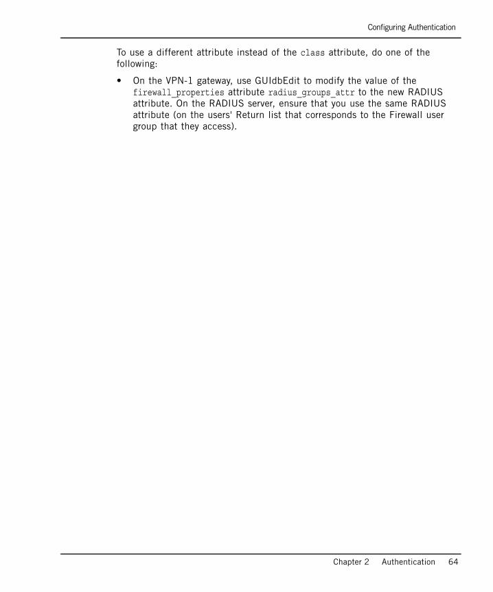
Configuring Authentication
Chapter 2 Authentication 64
To use a different attribute instead of the class attribute, do one of the following:
• On the VPN-1 gateway, use GUIdbEdit to modify the value of the firewall_properties attribute radius_groups_attr to the new RADIUS attribute. On the RADIUS server, ensure that you use the same RADIUS attribute (on the users' Return list that corresponds to the Firewall user group that they access).
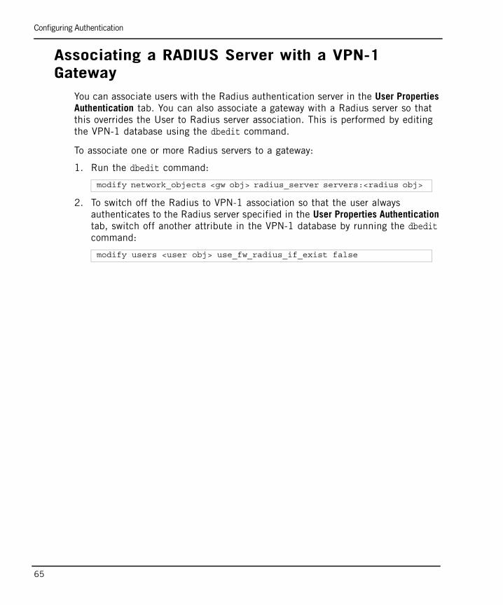
Configuring Authentication
65
Associating a RADIUS Server with a VPN-1 Gateway
You can associate users with the Radius authentication server in the User Properties Authentication tab. You can also associate a gateway with a Radius server so that this overrides the User to Radius server association. This is performed by editing the VPN-1 database using the dbedit command.
To associate one or more Radius servers to a gateway:
1. Run the dbedit command:
2. To switch off the Radius to VPN-1 association so that the user always authenticates to the Radius server specified in the User Properties Authentication tab, switch off another attribute in the VPN-1 database by running the dbedit command:
modify network_objects <gw obj> radius_server servers:<radius obj>
modify users <user obj> use_fw_radius_if_exist false

Configuring Authentication
Chapter 2 Authentication 66
Configuring a VPN-1 Gateway to use SecurIDTo configure a VPN-1 gateway to use SecurID:
1. Generate and copy the sdconf.rec file from the ACE/Server to:
• /var/ace/sdconf.rec on UNIX, Linux or IPSO
• %SystemRoot%\System32\sdconf.rec on Windows
2. In SmartDashboard, right-click the gateway object and select Edit > Authentication page.
3. Enable SecurID authentication.
4. Define a user group by selecting Manage > Users & Administrators > New > User Group (for example, SecurID_Users).
5. Enable SecurID authentication for VPN-1 users by selecting Manage > Users and Administrators > New > User by Template > Default..
6. Enable SecurID authentication for users without VPN-1 user accounts by creating an External User Profile. Select Manage > Users and Administrators > New > External User Profile > Match all users... or Match by domain.... If you support more than one external authentication scheme, set up your External User Profiles with the Match By Domain setting.
7. For all User Profiles and Templates, configure the following:
a. In the General tab, enter the default login name for the ACE/Server. (When configuring Match all users as an External User Profile, the name “generic*” is automatically assigned).
b. In the Personal tab, change the Expiration Date.
c. In the Authentication tab, select SecurID from the drop-down list.
d. In the Groups tab, add the User Profile to the SecurID group.
8. Verify that communication between the firewall and the ACE/Server are not NATed in the Address Translation Rule Base.
9. Save, verify, and install the policy.
Configuring Authentication
67
When a VPN-1 gateway has multiple interfaces, the SecurID agent in VPN-1 sometimes uses the wrong interface IP to decrypt the reply from the ACE/Server, and authentication fails.
To overcome this problem, place a new text file, named sdopts.rec, in the same directory as sdconf.rec. The file should contain the CLIENT_IP=<ip> line, where <ip> is the primary IP address of VPN-1, as defined on the ACE/Server. This is the IP address of the interface to which the server is routed.
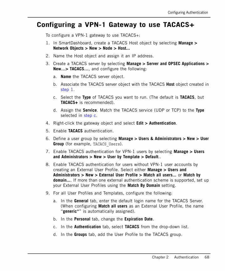
Configuring Authentication
Chapter 2 Authentication 68
Configuring a VPN-1 Gateway to use TACACS+To configure a VPN-1 gateway to use TACACS+:
1. In SmartDashboard, create a TACACS Host object by selecting Manage > Network Objects > New > Node > Host...
2. Name the Host object and assign it an IP address.
3. Create a TACACS server by selecting Manage > Server and OPSEC Applications > New…> TACACS…, and configure the following:
a. Name the TACACS server object.
b. Associate the TACACS server object with the TACACS Host object created in step 1.
c. Select the Type of TACACS you want to run. (The default is TACACS, but TACACS+ is recommended).
d. Assign the Service. Match the TACACS service (UDP or TCP) to the Type selected in step c.
4. Right-click the gateway object and select Edit > Authentication.
5. Enable TACACS authentication.
6. Define a user group by selecting Manage > Users & Administrators > New > User Group (for example, TACACS_Users).
7. Enable TACACS authentication for VPN-1 users by selecting Manage > Users and Administrators > New > User by Template > Default..
8. Enable TACACS authentication for users without VPN-1 user accounts by creating an External User Profile. Select either Manage > Users and Administrators > New > External User Profile > Match all users... or Match by domain.... If more than one external authentication scheme is supported, set up your External User Profiles using the Match By Domain setting.
9. For all User Profiles and Templates, configure the following:
a. In the General tab, enter the default login name for the TACACS Server. (When configuring Match all users as an External User Profile, the name “generic*” is automatically assigned).
b. In the Personal tab, change the Expiration Date.
c. In the Authentication tab, select TACACS from the drop-down list.
d. In the Groups tab, add the User Profile to the TACACS group.

Configuring Authentication
69
10. Verify that communication between the firewall and the TACACS server is not NATed in the Address Translation Rule Base.
11. Save, verify, and install the policy.
Configuring Policy for Groups of Windows UsersYou can create policy rules for groups of users that are not defined on the SmartCenter server, but are defined either on the gateway’s host (a Windows machine) or in the Windows machine’s trusted domain.
To configure policy for groups of Windows users:
1. Enable this feature using the Graphical Database Tool (GUIdbEdit).
2. Change the value of the add_nt_groups attribute to true. (This attribute is located under the firewall_properties object in the properties table.)
3. Ensure that the user belongs to a Windows user group.
4. In the SmartDashboard, create a user group with the name: Windows_<Windows user group which the user belongs to>. The group may be empty.
5. Define a Generic User Profile for each user that uses an operating system password as its authentication scheme.

ConnectivityThis section describes how to give internal users and resources unrestricted yet secure connectivity across the gateway.

99
Chapter 3Network Address Translation (NAT)
In This Chapter
The Need to Conceal IP Addresses page 100
Check Point Solution for Network Address Translation page 101
Planning Considerations for NAT page 114
Configuring NAT page 116
Advanced NAT Configuration page 122
The Need to Conceal IP Addresses
100
The Need to Conceal IP AddressesIn an IP network, each computer is assigned a unique IP address that defines both the host and the network. Many computers in an organization have private, non-routable IP addresses, but also require access to the Internet. Normally, it is impossible to give each computer an Internet-routable IP address due to the lack of available public IP addresses and administrative constraints.
IPv4 (the current version of IP) provides only 32 bits of address space. This makes available IP addresses scarce since most addresses have already been assigned. Internet Service Providers usually allocate only one or a few addresses at a time. Larger companies may purchase several addresses for use, but purchasing addresses for every computer on a network is not practical for most companies.
Even if additional public IP addresses become available, changing the addresses of every machine in a large network would be both labor intensive and time consuming.
Whether computers have routable or non-routable addresses, the administrator may want to conceal their real addresses for security reasons, for example, to ensure that addresses cannot be seen from outside the organization or from other parts of the same organization. A network’s internal addresses contains the topology of the network and, therefore, hiding this information greatly enhances security.

Check Point Solution for Network Address Translation
Chapter 3 Network Address Translation (NAT) 101
Check Point Solution for Network Address Translation
In This Section
Public and Private IP addressesPublic IP addresses are those that are routable on the Internet. RFC 1918 documents private address spaces that can be used on internal networks and do not have hosts directly connected to the Internet. The Internet Assigned Numbers Authority (IANA) has set aside the following three blocks of IP addresses for internal (private) network use:
• Class A network numbers: 10.0.0.0–10.255.255.255
• Class B network numbers: 172.16.0.0–172.31.255.255
• Class C network numbers: 192.168.0.0–192.168.255.255
When an enterprise employs an intranet using private addresses, a VPN-1 NAT gateway connects the intranet to the Internet. The Global Properties > Non Unique IP Address Ranges page specifies the address ranges that VPN-1 considers private (non-unique).
Public and Private IP addresses page 101
NAT in VPN-1 page 102
Static NAT page 103
Hide NAT page 104
Automatic and Manual NAT Rules page 105
Automatic Hide NAT for Internal Networks page 106
Address Translation Rule Base page 107
Bidirectional NAT page 108
Understanding Automatically Generated Rules page 109
Port Translation page 111
NAT and Anti-Spoofing page 111
Routing Issues page 111
Disabling NAT in a VPN Tunnel page 113

Check Point Solution for Network Address Translation
102
NAT in VPN-1Network Address Translation (NAT) involves replacing one IP address with another. NAT can change both the source and destination address inside the packet. This means that a packet that is sent from the internal (protected) side to the external (unprotected) side of the firewall appears to the destination as if it came from a different address, and the packet that is sent from the external to the internal side of the firewall arrives at the correct address.
VPN-1 supports two kinds of NAT:
• Static NAT: Each private address is translated to a corresponding public address. In a typical Static NAT scenario, with a number of machines in an internal network, the address of each machine is translated to a different public IP address. It is a many-to-many translation. Static NAT allows machines on both sides of the VPN-1 gateway to initiate connections, for example, so that internal servers can be made available externally.
• Hide NAT: A single public address is used to represent multiple computers with private addresses on the internal network. Hide NAT is a many-to-one translation. Hide NAT allows connections to be initiated only from the protected side of the VPN-1 gateway.
NAT can be performed on Check Point network objects, nodes, networks, address ranges, and dynamic objects. NAT can be defined either automatically through the network object, by automatically adding rules to the Address Translation Rule Base, or manually by defining rules in the Address Translation Rule Base.
Manually creating NAT Rules adds extra flexibility. For example, in addition to translating IP addresses, you can translate the service or the destination port numbers. Port number translation is a type of Static NAT, in which one port number is translated to another port number.

Check Point Solution for Network Address Translation
Chapter 3 Network Address Translation (NAT) 103
Static NAT Static NAT translates each private address to a corresponding public address.
Static NAT on a node translates the private address of the node to a public address. Static NAT on a network or address range translates each IP address in the network or range to a corresponding public IP address, starting from the defined Static IP address.
In Figure 3-1, the address range 10.1.1.2 to 10.1.1.10 is hidden behind the NAT range 192.168.0.2-192.168.0.11. The diagram shows a connection that originates at 10.1.1.3, and the source and destination translation of the original and reply packet.Figure 3-1 Static NAT on an Address Range

Check Point Solution for Network Address Translation
104
Hide NATThe NAT gateway makes it possible to share a single public address with multiple computers that have private addresses on your intranet. The Internet is unaware of the division you have created between the Internet and your intranet, and treats your multiple computer connection as a single connection.
Hide NAT allows only connections that originate on the internal network. This lets an internal host initiate a connection to both inside and outside the intranet, however, a host outside the network cannot initiate a connection to an internal host.
The Hide Address is the address behind which the internal network, address range or node is hidden. You can opt to hide the internal address(es) either:
• Behind a virtual IP address, which is a public (routable) IP address that does not belong to any real machine, or
• Behind the IP address of the VPN-1 interface through which the packet is routed out of (formerly known as “Hiding behind IP address 0.0.0.0”).
In Figure 3-2, the address range 10.1.1.2 to 10.1.1.10 is hidden behind the address of the external VPN-1 interface (192.168.0.1). The diagram shows a connection that originates at 10.1.1.3, and the source and destination translation of the original and reply packet.Figure 3-2 Hide NAT on An Address Range
Check Point Solution for Network Address Translation
Chapter 3 Network Address Translation (NAT) 105
How Hide NAT WorksIn Hide mode, the source port numbers of the packets are modified. When return packets enter a firewall, VPN-1 use the port number to determine to which internal machines the packets are destined. Port numbers are dynamically assigned from two pools of numbers: 600 to 1023 and 10,000 to 60,000.
Port numbers are normally assigned from the second pool. The first pool is used for only three services: rlogin (destination port 512), rshell (destination port 513) and rexec (destination port 514). If the connection uses one of these services, and the original source port is less than 1024, then a port number is assigned from the first pool. This behavior is configurable.
VPN-1 keeps track of the port numbers assigned, so that the original port number is correctly restored for return packets and a port number that is currently in use is not assigned again to a new connection.
Hide NAT has a capacity of 50,000 connections per server. The Hide NAT capacity limit is only reached if more than 50,000 connections from Hide NATed internal clients are simultaneously directed at a single server on the unprotected side of the VPN-1 gateway—a highly unlikely scenario.
Automatic and Manual NAT RulesNAT can be defined automatically through the network object (node, network or address range). When you define NAT this way, rules are automatically added to the Address Translation Rule Base.
You can manually specify NAT rules by adding or editing NAT rules in the Address Translation Rule Base. VPN-1 validates manual NAT rules, helping to avoid mistakes in the setup process. Creating manual NAT Rules gives maximum control over the way NAT functions. You can specify the source, destination and service separately for both the original and the translated packet.
When creating Manual NAT rules, you must define the translated network objects in addition to the original objects.
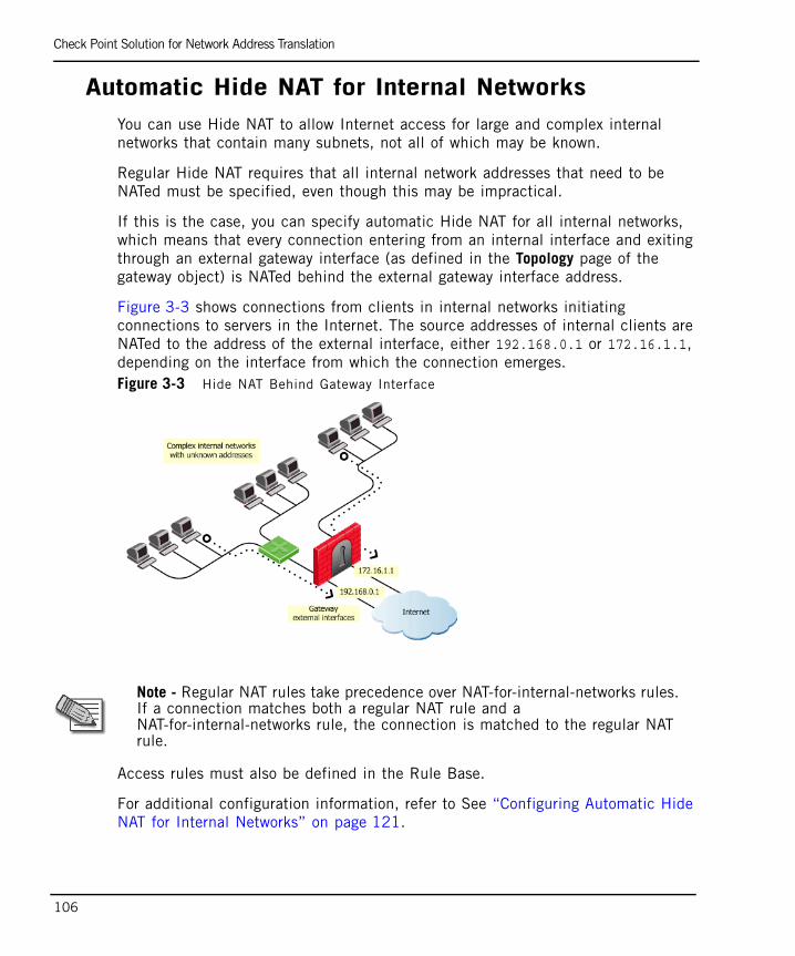
Check Point Solution for Network Address Translation
106
Automatic Hide NAT for Internal Networks You can use Hide NAT to allow Internet access for large and complex internal networks that contain many subnets, not all of which may be known.
Regular Hide NAT requires that all internal network addresses that need to be NATed must be specified, even though this may be impractical.
If this is the case, you can specify automatic Hide NAT for all internal networks, which means that every connection entering from an internal interface and exiting through an external gateway interface (as defined in the Topology page of the gateway object) is NATed behind the external gateway interface address.
Figure 3-3 shows connections from clients in internal networks initiating connections to servers in the Internet. The source addresses of internal clients are NATed to the address of the external interface, either 192.168.0.1 or 172.16.1.1, depending on the interface from which the connection emerges.Figure 3-3 Hide NAT Behind Gateway Interface
Access rules must also be defined in the Rule Base.
For additional configuration information, refer to See “Configuring Automatic Hide NAT for Internal Networks” on page 121.
Note - Regular NAT rules take precedence over NAT-for-internal-networks rules. If a connection matches both a regular NAT rule and a NAT-for-internal-networks rule, the connection is matched to the regular NAT rule.
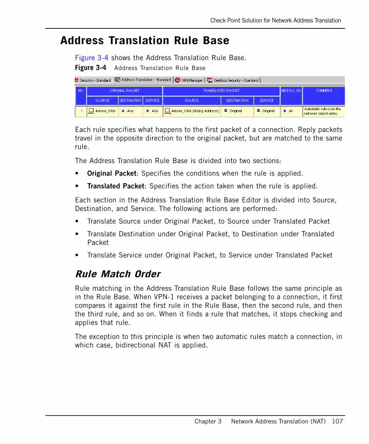
Check Point Solution for Network Address Translation
Chapter 3 Network Address Translation (NAT) 107
Address Translation Rule BaseFigure 3-4 shows the Address Translation Rule Base.Figure 3-4 Address Translation Rule Base
Each rule specifies what happens to the first packet of a connection. Reply packets travel in the opposite direction to the original packet, but are matched to the same rule.
The Address Translation Rule Base is divided into two sections:
• Original Packet: Specifies the conditions when the rule is applied.
• Translated Packet: Specifies the action taken when the rule is applied.
Each section in the Address Translation Rule Base Editor is divided into Source, Destination, and Service. The following actions are performed:
• Translate Source under Original Packet, to Source under Translated Packet
• Translate Destination under Original Packet, to Destination under Translated Packet
• Translate Service under Original Packet, to Service under Translated Packet
Rule Match OrderRule matching in the Address Translation Rule Base follows the same principle as in the Rule Base. When VPN-1 receives a packet belonging to a connection, it first compares it against the first rule in the Rule Base, then the second rule, and then the third rule, and so on. When it finds a rule that matches, it stops checking and applies that rule.
The exception to this principle is when two automatic rules match a connection, in which case, bidirectional NAT is applied.
Check Point Solution for Network Address Translation
108
Bidirectional NATBidirectional NAT applies to automatic NAT rules in the Address Translation Rule Base and allows two automatic NAT rules to match a connection. Without bidirectional NAT, only one automatic NAT rule can match a connection.
When NAT is defined for a network object, an automatic NAT rule is generated which performs the required translation. If there are two network objects, where one is the source of a connection and the other is the destination, using bidirectional NAT, both automatic NAT rules are applied and both objects are translated.
The logic behind bidirectional NAT is:
• If the first match of a connection is on a Manual NAT rule, no further checking of the NAT Rule Base is performed.
• If the first match of a connection is on an Automatic NAT rule, the rest of the NAT Rule Base is checked, one rule at a time, to verify whether another Automatic NAT rule matches the connection. If it finds another match, both rules are matched and no further checking is performed.
The operation of bidirectional NAT can be tracked using the SmartView Tracker and the NAT Rule Number and NAT Additional Rule Number fields . The additional rule is the rule that matches the automatic translation performed on the second object in bidirectional NAT.
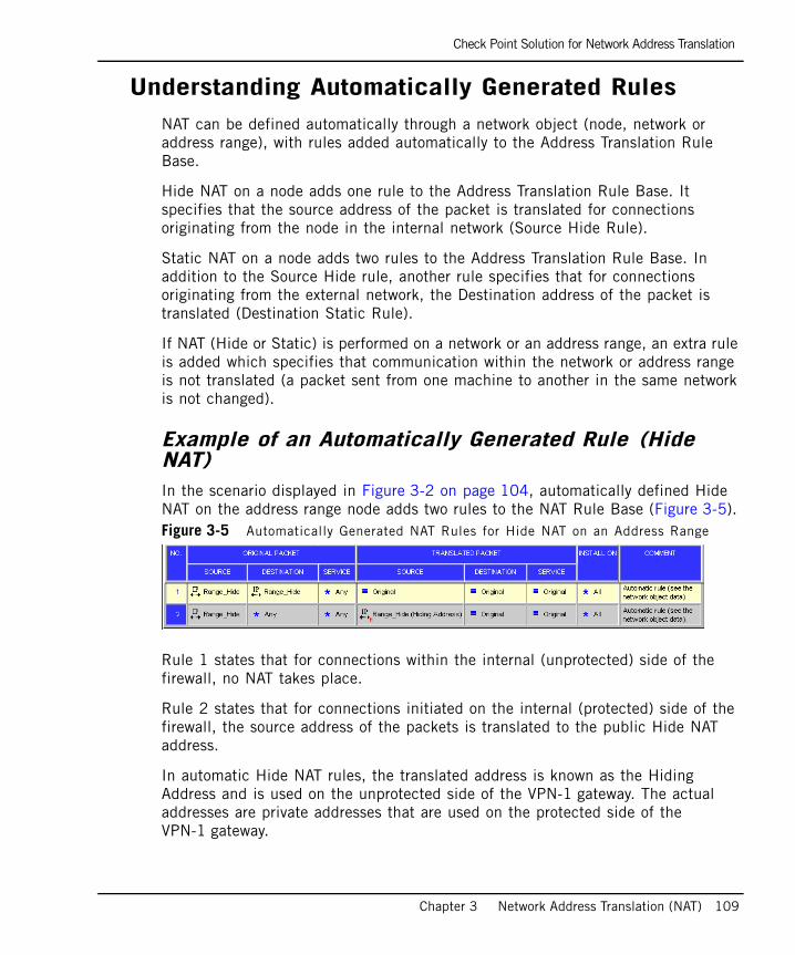
Check Point Solution for Network Address Translation
Chapter 3 Network Address Translation (NAT) 109
Understanding Automatically Generated RulesNAT can be defined automatically through a network object (node, network or address range), with rules added automatically to the Address Translation Rule Base.
Hide NAT on a node adds one rule to the Address Translation Rule Base. It specifies that the source address of the packet is translated for connections originating from the node in the internal network (Source Hide Rule).
Static NAT on a node adds two rules to the Address Translation Rule Base. In addition to the Source Hide rule, another rule specifies that for connections originating from the external network, the Destination address of the packet is translated (Destination Static Rule).
If NAT (Hide or Static) is performed on a network or an address range, an extra rule is added which specifies that communication within the network or address range is not translated (a packet sent from one machine to another in the same network is not changed).
Example of an Automatically Generated Rule (Hide NAT)In the scenario displayed in Figure 3-2 on page 104, automatically defined Hide NAT on the address range node adds two rules to the NAT Rule Base (Figure 3-5). Figure 3-5 Automatically Generated NAT Rules for Hide NAT on an Address Range
Rule 1 states that for connections within the internal (unprotected) side of the firewall, no NAT takes place.
Rule 2 states that for connections initiated on the internal (protected) side of the firewall, the source address of the packets is translated to the public Hide NAT address.
In automatic Hide NAT rules, the translated address is known as the Hiding Address and is used on the unprotected side of the VPN-1 gateway. The actual addresses are private addresses that are used on the protected side of the VPN-1 gateway.
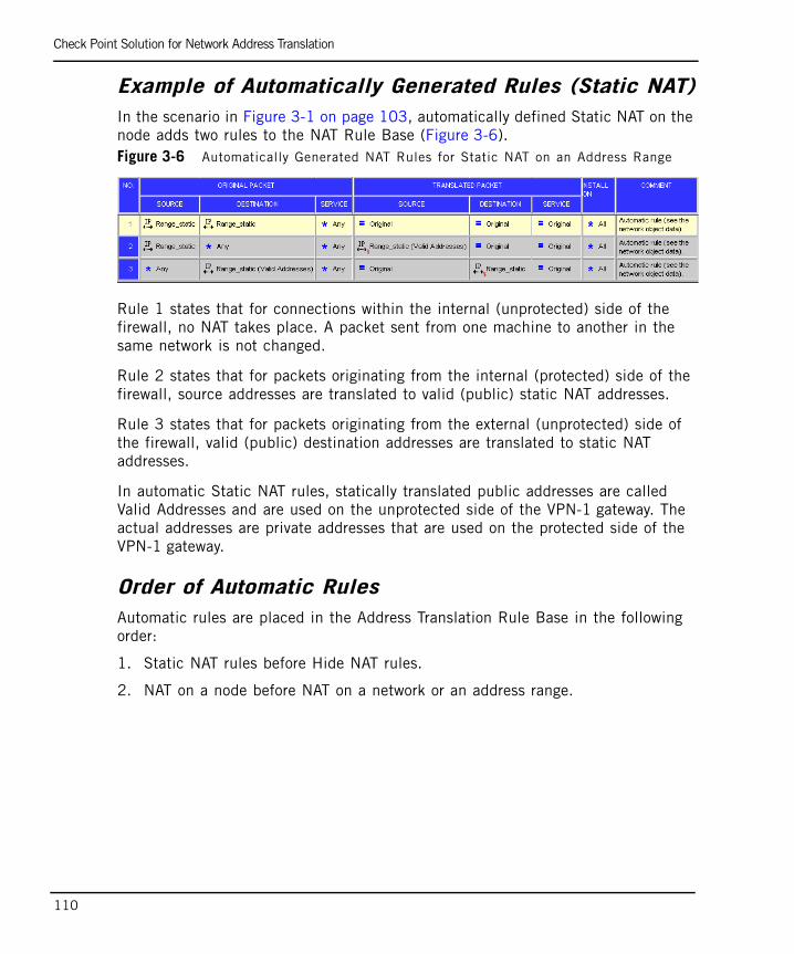
Check Point Solution for Network Address Translation
110
Example of Automatically Generated Rules (Static NAT)In the scenario in Figure 3-1 on page 103, automatically defined Static NAT on the node adds two rules to the NAT Rule Base (Figure 3-6). Figure 3-6 Automatically Generated NAT Rules for Static NAT on an Address Range
Rule 1 states that for connections within the internal (unprotected) side of the firewall, no NAT takes place. A packet sent from one machine to another in the same network is not changed.
Rule 2 states that for packets originating from the internal (protected) side of the firewall, source addresses are translated to valid (public) static NAT addresses.
Rule 3 states that for packets originating from the external (unprotected) side of the firewall, valid (public) destination addresses are translated to static NAT addresses.
In automatic Static NAT rules, statically translated public addresses are called Valid Addresses and are used on the unprotected side of the VPN-1 gateway. The actual addresses are private addresses that are used on the protected side of the VPN-1 gateway.
Order of Automatic RulesAutomatic rules are placed in the Address Translation Rule Base in the following order:
1. Static NAT rules before Hide NAT rules.
2. NAT on a node before NAT on a network or an address range.
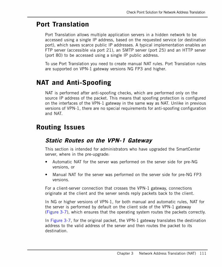
Check Point Solution for Network Address Translation
Chapter 3 Network Address Translation (NAT) 111
Port Translation Port Translation allows multiple application servers in a hidden network to be accessed using a single IP address, based on the requested service (or destination port), which saves scarce public IP addresses. A typical implementation enables an FTP server (accessible via port 21), an SMTP server (port 25) and an HTTP server (port 80) to be accessed using a single IP public address.
To use Port Translation you need to create manual NAT rules. Port Translation rules are supported on VPN-1 gateway versions NG FP3 and higher.
NAT and Anti-SpoofingNAT is performed after anti-spoofing checks, which are performed only on the source IP address of the packet. This means that spoofing protection is configured on the interfaces of the VPN-1 gateway in the same way as NAT. Unlike in previous versions of VPN-1, there are no special requirements for anti-spoofing configuration and NAT.
Routing Issues
Static Routes on the VPN-1 GatewayThis section is intended for administrators who have upgraded the SmartCenter server, where in the pre-upgrade:
• Automatic NAT for the server was performed on the server side for pre-NG versions, or
• Manual NAT for the server was performed on the server side for pre-NG FP3 versions.
For a client-server connection that crosses the VPN-1 gateway, connections originate at the client and the server sends reply packets back to the client.
In NG or higher versions of VPN-1, for both manual and automatic rules, NAT for the server is performed by default on the client side of the VPN-1 gateway (Figure 3-7), which ensures that the operating system routes the packets correctly.
In Figure 3-7, for the original packet, the VPN-1 gateway translates the destination address to the valid address of the server and then routes the packet to its destination.
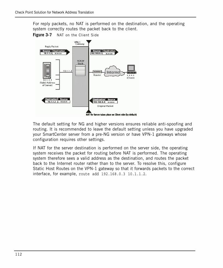
Check Point Solution for Network Address Translation
112
For reply packets, no NAT is performed on the destination, and the operating system correctly routes the packet back to the client. Figure 3-7 NAT on the Client Side
The default setting for NG and higher versions ensures reliable anti-spoofing and routing. It is recommended to leave the default setting unless you have upgraded your SmartCenter server from a pre-NG version or have VPN-1 gateways whose configuration requires other settings.
If NAT for the server destination is performed on the server side, the operating system receives the packet for routing before NAT is performed. The operating system therefore sees a valid address as the destination, and routes the packet back to the Internet router rather than to the server. To resolve this, configure Static Host Routes on the VPN-1 gateway so that it forwards packets to the correct interface, for example, route add 192.168.0.3 10.1.1.2.
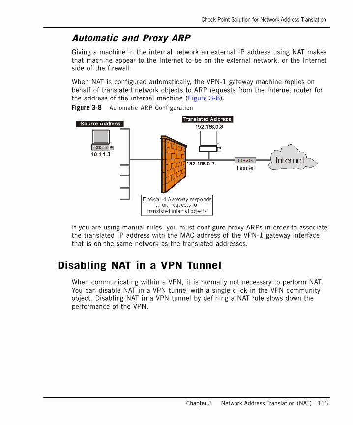
Check Point Solution for Network Address Translation
Chapter 3 Network Address Translation (NAT) 113
Automatic and Proxy ARPGiving a machine in the internal network an external IP address using NAT makes that machine appear to the Internet to be on the external network, or the Internet side of the firewall.
When NAT is configured automatically, the VPN-1 gateway machine replies on behalf of translated network objects to ARP requests from the Internet router for the address of the internal machine (Figure 3-8).Figure 3-8 Automatic ARP Configuration
If you are using manual rules, you must configure proxy ARPs in order to associate the translated IP address with the MAC address of the VPN-1 gateway interface that is on the same network as the translated addresses.
Disabling NAT in a VPN TunnelWhen communicating within a VPN, it is normally not necessary to perform NAT. You can disable NAT in a VPN tunnel with a single click in the VPN community object. Disabling NAT in a VPN tunnel by defining a NAT rule slows down the performance of the VPN.
Planning Considerations for NAT
114
Planning Considerations for NATIn This Section
Hide Versus StaticFor protocols where the port number cannot be changed, Hide NAT cannot be used.
When the external server must distinguish between clients based on their IP addresses, Hide NAT cannot be used because all clients share the same IP address under Hide NAT.
To allow connections from the external network to the internal network, only Static NAT can be used.
Automatic Versus Manual RulesAutomatic NAT rules are easy to configure and therefore are less prone to configuration errors. Automatic ARP configuration is only effective for automatic rules.
Manually defining NAT rules can be complicated, but it gives you complete control over NAT. The following operations can only be performed using manual NAT rules:
• Restricting rules to specified destination IP addresses and to specified source IP addresses.
• Translating both source and destination IP addresses in the same packet.
• Performing Static NAT in only one direction.
• Translating services (destination ports).
• Restricting rules to specified services (ports).
• Performing NAT on dynamic objects.
Hide Versus Static page 114
Automatic Versus Manual Rules page 114
Choosing the Hide Address in Hide NAT page 115

Planning Considerations for NAT
Chapter 3 Network Address Translation (NAT) 115
Choosing the Hide Address in Hide NATThe Hide Address is the address behind which the network, address range or node is hidden.
It is possible to hide behind either the interface of the Install on Gateway or a specified IP address.
Choosing a fixed public IP address is a good option if you want to hide the address of the VPN-1 gateway, however, it means you have to use an extra publicly routable IP address.
Choosing to hide behind the address of the Install On Gateway is a good option for administrative purposes, for example, if the external IP address of the firewall changes, there is no need to change the NAT settings.
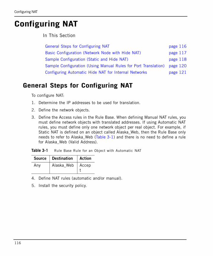
Configuring NAT
116
Configuring NATIn This Section
General Steps for Configuring NATTo configure NAT:
1. Determine the IP addresses to be used for translation.
2. Define the network objects.
3. Define the Access rules in the Rule Base. When defining Manual NAT rules, you must define network objects with translated addresses. If using Automatic NAT rules, you must define only one network object per real object. For example, if Static NAT is defined on an object called Alaska_Web, then the Rule Base only needs to refer to Alaska_Web (Table 3-1) and there is no need to define a rule for Alaska_Web (Valid Address).
4. Define NAT rules (automatic and/or manual).
5. Install the security policy.
General Steps for Configuring NAT page 116
Basic Configuration (Network Node with Hide NAT) page 117
Sample Configuration (Static and Hide NAT) page 118
Sample Configuration (Using Manual Rules for Port Translation) page 120
Configuring Automatic Hide NAT for Internal Networks page 121
Table 3-1 Rule Base Rule for an Object with Automatic NAT
Source Destination Action
Any Alaska_Web Accept
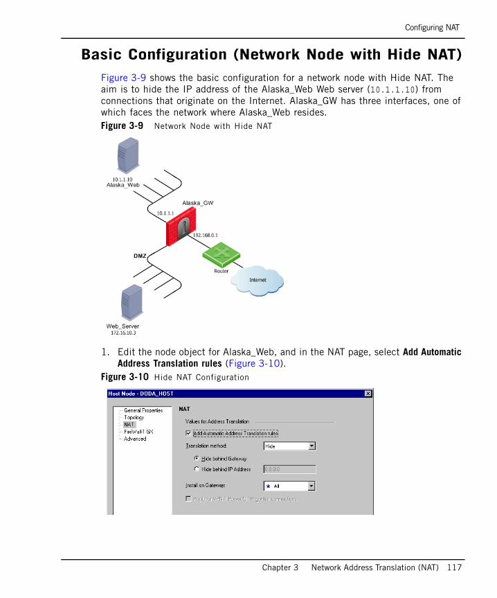
Configuring NAT
Chapter 3 Network Address Translation (NAT) 117
Basic Configuration (Network Node with Hide NAT)Figure 3-9 shows the basic configuration for a network node with Hide NAT. The aim is to hide the IP address of the Alaska_Web Web server (10.1.1.10) from connections that originate on the Internet. Alaska_GW has three interfaces, one of which faces the network where Alaska_Web resides.Figure 3-9 Network Node with Hide NAT
1. Edit the node object for Alaska_Web, and in the NAT page, select Add Automatic Address Translation rules (Figure 3-10).
Figure 3-10 Hide NAT Configuration
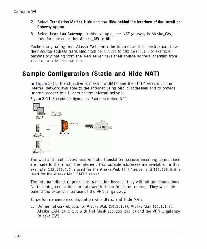
Configuring NAT
118
2. Select Translation Method Hide and the Hide behind the interface of the Install on Gateway option.
3. Select Install on Gateway. In this example, the NAT gateway is Alaska_GW, therefore, select either Alaska_GW or All.
Packets originating from Alaska_Web, with the Internet as their destination, have their source address translated from 10.1.1.10 to 192.168.0.1. For example, packets originating from the Web server have their source address changed from 172.16.10.3 to 192.168.0.1.
Sample Configuration (Static and Hide NAT)In Figure 3-11, the objective is make the SMTP and the HTTP servers on the internal network available to the Internet using public addresses and to provide Internet access to all users on the internal network.Figure 3-11 Sample Configuration (Static and Hide NAT)
The web and mail servers require static translation because incoming connections are made to them from the Internet. Two routable addresses are available. In this example, 192.168.0.5 is used for the Alaska.Web HTTP server and 192.168.0.6 is used for the Alaska.Mail SMTP server.
The internal clients require hide translation because they will initiate connections. No incoming connections are allowed to them from the Internet. They will hide behind the external interface of the VPN-1 gateway.
To perform a sample configuration with Static and Hide NAT:
1. Define network objects for Alaska.Web (10.1.1.5), Alaska.Mail (10.1.1.6), Alaska_LAN (10.1.1.0 with Net Mask 255.255.255.0) and the VPN-1 gateway (Alaska.GW).

Configuring NAT
Chapter 3 Network Address Translation (NAT) 119
2. Edit the Alaska.Web object and in the NAT page, select Add Automatic Address Translation Rules.
3. Select Static as the Translation Method and define the Translate to IP Address as 192.168.0.5.
4. For Alaska.Mail, select Static as the Translation Method and define the Translate to IP Address as 192.168.0.6.
5. Edit the Alaska_LAN object and in the NAT page, select Hide as the Translation Method and then select Hide behind the interface of the Install On Gateway. The effective Hide address for the internal clients on Alaska_LAN is therefore 192.168.0.1. Figure 3-12 displays the resulting Address Translation Rule Base.
Figure 3-12 Automatic Address Translation Rule Base for Static and Hide NAT

Configuring NAT
120
Sample Configuration (Using Manual Rules for Port Translation)
In Figure 3-13, the objective is to make both a Web server and a mail server in a DMZ network available from the Internet using a single IP address. Hide NAT is performed on all addresses in the DMZ.Figure 3-13 Sample Configuration (Port Translation using Manual NAT)
To perform a sample configuration using manual rules for port translation:
1. Define network objects for the network Alaska.DMZ.LAN (172.16.0.0 with Net Mask 255.255.0.0), the Web server Alaska_DMZ_Web (172.16.1.7), the Mail server Alaska_DMZ_Mail (172.16.1.5) and the VPN-1 gateway (Alaska.GW).
2. In the NAT tab on the Alaska.DMZ.LAN network object, select Add Automatic Address Translation Rules.
3. Select Hide as the Translation Method and then Hide behind the interface of the Install on Gateway. This step adds two automatic rules to the Address Translation Rule Base (Rules 1 and 2 in Figure 3-14).
4. In the Address Translation Rule Base, define a Manual NAT rule that translates requests for the HTTP service to the Web server (Rule 3 in Figure 3-14) and a Manual NAT rule to translate SMTP requests to the SMTP server (Rule 4 in Figure 3-14).
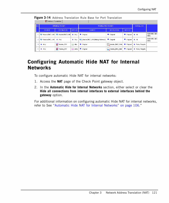
Configuring NAT
Chapter 3 Network Address Translation (NAT) 121
Figure 3-14 Address Translation Rule Base for Port Translation
Configuring Automatic Hide NAT for Internal Networks
To configure automatic Hide NAT for internal networks:
1. Access the NAT page of the Check Point gateway object.
2. In the Automatic Hide for Internal Networks section, either select or clear the Hide all connections from internal interfaces to external interfaces behind the gateway option.
For additional information on configuring automatic Hide NAT for internal networks, refer to See “Automatic Hide NAT for Internal Networks” on page 106.”

Advanced NAT Configuration
122
Advanced NAT ConfigurationIn This Section
Allowing Connections Between Translated Objects on Different Gateway Interfaces
The following sections describe how to allow connections in both directions between statically translated objects (nodes, networks or address ranges) on different VPN-1 gateway interfaces.
If NAT is defined through the network object (as opposed to using Manual NAT Rules), then you must ensure that bidirectional NAT is enabled.
Allowing Connections Between Translated Objects on Different Gateway Interfaces page 122
Enabling Communication for Internal Networks with Overlapping IP Addresses page 123
SmartCenter Behind NAT page 127
IP Pool NAT page 131
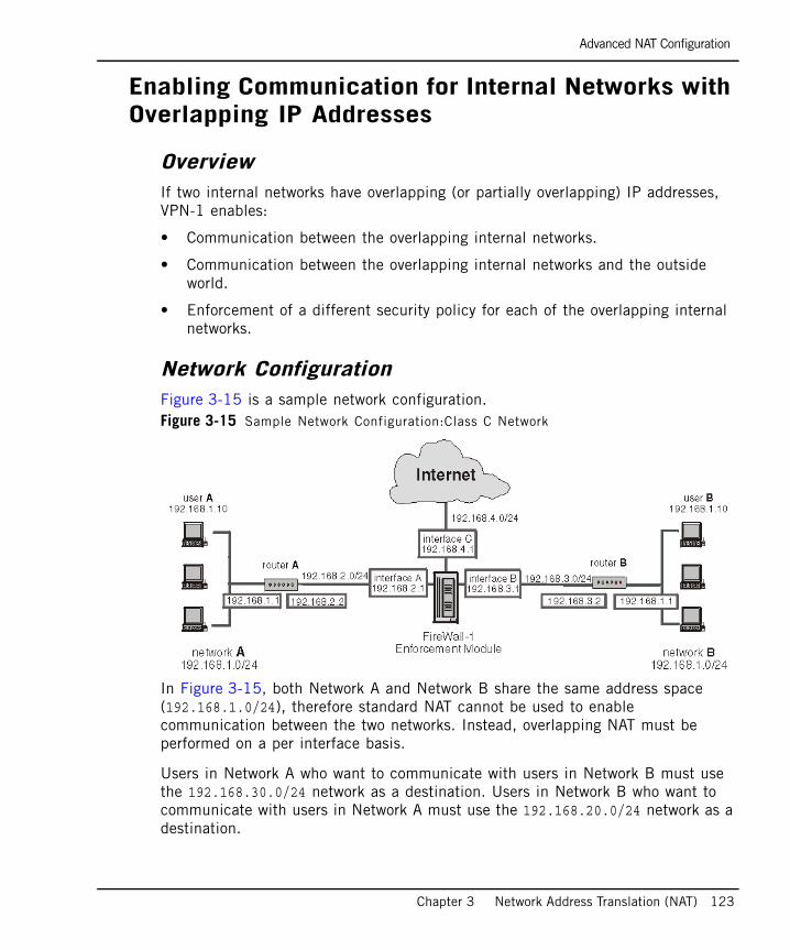
Advanced NAT Configuration
Chapter 3 Network Address Translation (NAT) 123
Enabling Communication for Internal Networks with Overlapping IP Addresses
OverviewIf two internal networks have overlapping (or partially overlapping) IP addresses, VPN-1 enables:
• Communication between the overlapping internal networks.
• Communication between the overlapping internal networks and the outside world.
• Enforcement of a different security policy for each of the overlapping internal networks.
Network ConfigurationFigure 3-15 is a sample network configuration.Figure 3-15 Sample Network Configuration:Class C Network
In Figure 3-15, both Network A and Network B share the same address space (192.168.1.0/24), therefore standard NAT cannot be used to enable communication between the two networks. Instead, overlapping NAT must be performed on a per interface basis.
Users in Network A who want to communicate with users in Network B must use the 192.168.30.0/24 network as a destination. Users in Network B who want to communicate with users in Network A must use the 192.168.20.0/24 network as a destination.
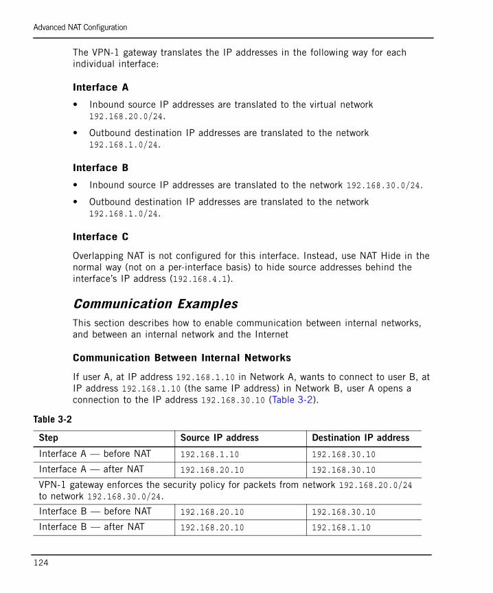
Advanced NAT Configuration
124
The VPN-1 gateway translates the IP addresses in the following way for each individual interface:
Interface A
• Inbound source IP addresses are translated to the virtual network 192.168.20.0/24.
• Outbound destination IP addresses are translated to the network 192.168.1.0/24.
Interface B
• Inbound source IP addresses are translated to the network 192.168.30.0/24.
• Outbound destination IP addresses are translated to the network 192.168.1.0/24.
Interface C
Overlapping NAT is not configured for this interface. Instead, use NAT Hide in the normal way (not on a per-interface basis) to hide source addresses behind the interface’s IP address (192.168.4.1).
Communication ExamplesThis section describes how to enable communication between internal networks, and between an internal network and the Internet
Communication Between Internal Networks
If user A, at IP address 192.168.1.10 in Network A, wants to connect to user B, at IP address 192.168.1.10 (the same IP address) in Network B, user A opens a connection to the IP address 192.168.30.10 (Table 3-2).
Table 3-2
Step Source IP address Destination IP address
Interface A — before NAT 192.168.1.10 192.168.30.10
Interface A — after NAT 192.168.20.10 192.168.30.10
VPN-1 gateway enforces the security policy for packets from network 192.168.20.0/24 to network 192.168.30.0/24.
Interface B — before NAT 192.168.20.10 192.168.30.10
Interface B — after NAT 192.168.20.10 192.168.1.10
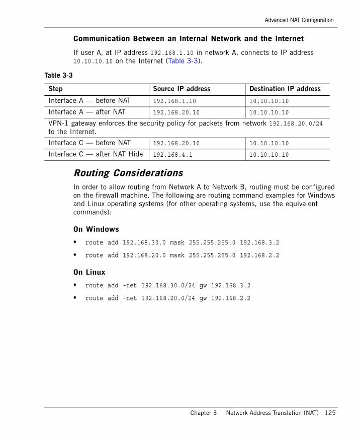
Advanced NAT Configuration
Chapter 3 Network Address Translation (NAT) 125
Communication Between an Internal Network and the Internet
If user A, at IP address 192.168.1.10 in network A, connects to IP address 10.10.10.10 on the Internet (Table 3-3).
Routing ConsiderationsIn order to allow routing from Network A to Network B, routing must be configured on the firewall machine. The following are routing command examples for Windows and Linux operating systems (for other operating systems, use the equivalent commands):
On Windows
• route add 192.168.30.0 mask 255.255.255.0 192.168.3.2
• route add 192.168.20.0 mask 255.255.255.0 192.168.2.2
On Linux
• route add -net 192.168.30.0/24 gw 192.168.3.2
• route add -net 192.168.20.0/24 gw 192.168.2.2
Table 3-3
Step Source IP address Destination IP address
Interface A — before NAT 192.168.1.10 10.10.10.10
Interface A — after NAT 192.168.20.10 10.10.10.10
VPN-1 gateway enforces the security policy for packets from network 192.168.20.0/24 to the Internet.
Interface C — before NAT 192.168.20.10 10.10.10.10
Interface C — after NAT Hide 192.168.4.1 10.10.10.10
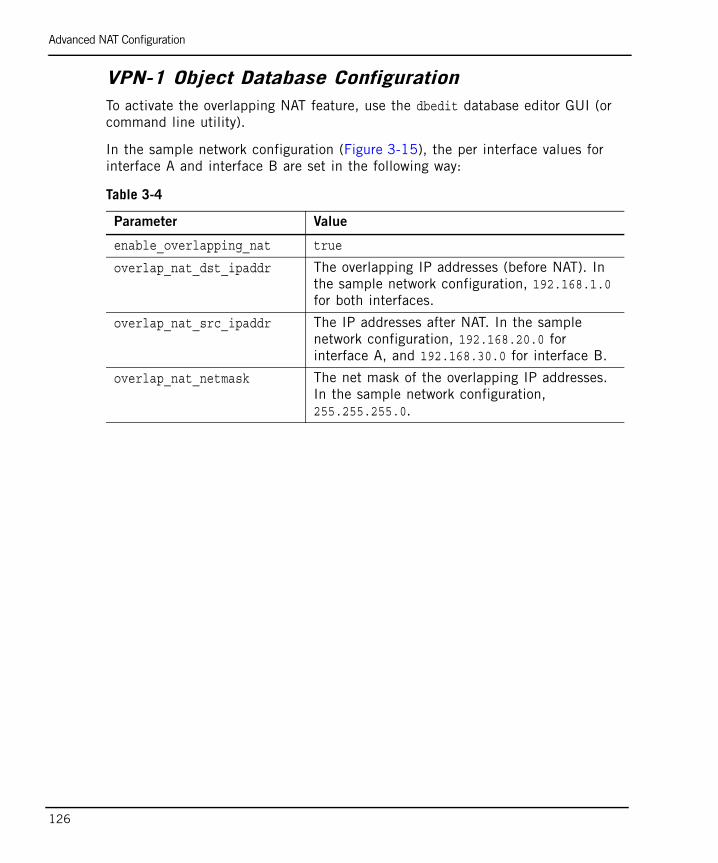
Advanced NAT Configuration
126
VPN-1 Object Database ConfigurationTo activate the overlapping NAT feature, use the dbedit database editor GUI (or command line utility).
In the sample network configuration (Figure 3-15), the per interface values for interface A and interface B are set in the following way:
Table 3-4
Parameter Value
enable_overlapping_nat true
overlap_nat_dst_ipaddr The overlapping IP addresses (before NAT). In the sample network configuration, 192.168.1.0 for both interfaces.
overlap_nat_src_ipaddr The IP addresses after NAT. In the sample network configuration, 192.168.20.0 for interface A, and 192.168.30.0 for interface B.
overlap_nat_netmask The net mask of the overlapping IP addresses. In the sample network configuration, 255.255.255.0.
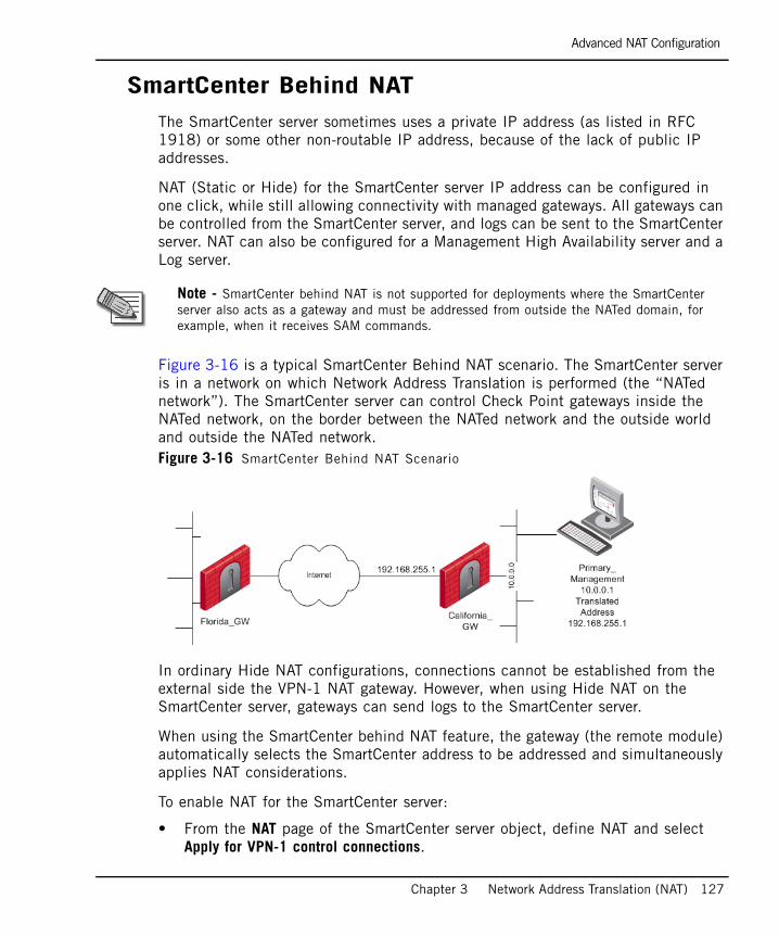
Advanced NAT Configuration
Chapter 3 Network Address Translation (NAT) 127
SmartCenter Behind NATThe SmartCenter server sometimes uses a private IP address (as listed in RFC 1918) or some other non-routable IP address, because of the lack of public IP addresses.
NAT (Static or Hide) for the SmartCenter server IP address can be configured in one click, while still allowing connectivity with managed gateways. All gateways can be controlled from the SmartCenter server, and logs can be sent to the SmartCenter server. NAT can also be configured for a Management High Availability server and a Log server.
Figure 3-16 is a typical SmartCenter Behind NAT scenario. The SmartCenter server is in a network on which Network Address Translation is performed (the “NATed network”). The SmartCenter server can control Check Point gateways inside the NATed network, on the border between the NATed network and the outside world and outside the NATed network. Figure 3-16 SmartCenter Behind NAT Scenario
In ordinary Hide NAT configurations, connections cannot be established from the external side the VPN-1 NAT gateway. However, when using Hide NAT on the SmartCenter server, gateways can send logs to the SmartCenter server.
When using the SmartCenter behind NAT feature, the gateway (the remote module) automatically selects the SmartCenter address to be addressed and simultaneously applies NAT considerations.
To enable NAT for the SmartCenter server:
• From the NAT page of the SmartCenter server object, define NAT and select Apply for VPN-1 control connections.
Note - SmartCenter behind NAT is not supported for deployments where the SmartCenter server also acts as a gateway and must be addressed from outside the NATed domain, for example, when it receives SAM commands.

Advanced NAT Configuration
128
Non-corresponding Gateway AddressesIn certain situations the gateway contacts the SmartCenter with an address that does not correspond to the remote gateway’s deployment, for example:
• When there are gateways from a version prior to NG with Application Intelligence. In this case, refer to SecureKnowledge solution SK15558 at https://secureknowledge.checkpoint.com/ for further instructions.
• When the gateway’s automatic selection does not conform with the routing of the gateway’s deployment. In this case, define the masters and loggers manually in order to allow the remote gateway to contact the SmartCenter server using the required address. When an inbound connection from a managed gateway enters the VPN-1 gateway, port translation is used to translate the hide address to the real IP address of the SmartCenter server.
To define masters and loggers:
• Select Use local definitions for Log Servers and Use local definitions for Masters and specify the correct IP addresses on the gateway.
This solution encompasses two scenarios:
• The remote gateway addresses the NATed IP when you want it to address the real IP.
• The remote gateway addresses the real IP when you want it to address the NATed IP. In this case, specify the SIC name of the SmartCenter server in the masters file.
Note that:
• Only one object can be defined with these settings, unless the second object is defined as a Secondary SmartCenter server or as a Log server.
• Ensure that you properly define the Topology settings on all gateways. In Figure 3-16, on California_GW, define the Primary_SmartCenter on its internal interface.
• All managed gateways and the SmartCenter server must be of version NG with Application Intelligence or higher.
• In previous versions, various work-arounds were required. All previous work-arounds still work with no changes in their behavior.

Advanced NAT Configuration
Chapter 3 Network Address Translation (NAT) 129
Configuring the SmartCenter Server ObjectTo configure the SmartCenter server object:
1. From the NAT page on the Primary_SmartCenter object, select either Static NAT or Hide NAT. If using Hide NAT, select Hide behind IP Address, for example, 192.168.55.1. Do not select Hide behind Gateway (address 0.0.0.0).
2. Select Install on Gateway to protect the NATed objects or network. Do not select All. For example, in Figure 3-16, Install on Gateway: California_GW.
3. Select Apply for VPN-1 control connections.
Configuring the Gateway ObjectUsing the example provided in Figure 3-16, ensure that the California_GW knows that the Primary_SmartCenter is behind it.
To configure the gateway object:
1. From the California_GW Topology page, define Interface Eth3.
2. In the General tab of the Interface Properties window, define the IP Address 10.0.0.0 and the Netmask 255.255.0.0.
In the Topology tab of the Interface Properties window, select Network defined by the interface IP and Net Mask.
Configuring Gateway Objects of Pre-NG with Application Intelligence Versions
For managed gateways that are not version NG with Application Intelligence or higher, you must define a dummy object. Using the example provided in Figure 3-16, if Florida_GW and California_GW have a version lower than NG with Application Intelligence, the dummy objects ensure that Florida_GW knows that its SmartCenter server has the address 192.168.255.1 and California_GW knows that its SmartCenter server has the address 10.0.0.1.
To configure pre-NG version with Application Intelligence gateway objects:
1. Define a dummy object with the translated address of the Primary_SmartCenter.
1. Name it, for example, Dummy-SmartCenter.
2. in the Check Point Products section of the General Properties page, select Secondary Management Station and Log Server.
3. Define a dummy object for the California_GW object by doing the following:
Advanced NAT Configuration
130
a. Name it.
b. Assign the IP Address 192.168.255.1.
c. Assign the address of the Primary SmartCenter NAT definition.
d. In the Check Point Products section of the General Properties page, select Secondary Management Station and Log Server.
e. From the Logs and Masters page:
i. Define the dummy object as a Master.
ii. Define the dummy object as a Log server (if the Log server is on a separate machine, define two virtual objects).
Advanced NAT Configuration
Chapter 3 Network Address Translation (NAT) 131
IP Pool NATAn IP Pool is a range of IP addresses (an address range, a network or a group of one of these objects) that is routable to the gateway. IP Pool NAT ensures proper routing for encrypted connections for the following two connection scenarios:
• SecuRemote/SecureClient to MEP (Multiple Entry Point) gateways
• Gateway to MEP gateways
When a connection is opened from a SecuRemote/SecureClient or a client behind a gateway to a server behind the MEP Gateways, the packets are routed through one of the MEP gateways. Return packets in the connection must be routed back through the same gateway in order to maintain the connection. To ensure that this occurs, each of the MEP gateways maintains a pool of IP addresses that are routable to the gateway. When a connection is opened to a server, the gateway substitutes an IP address from the IP pool for the source IP address. Reply packets from the server return to the gateway, which restores the original source IP address and forwards the packets to the source.
The pool of IP addresses is configured in the IP Pool page of the gateway object. For additional information on how IP Pool NAT is used in MEP scenarios, refer to Chapter 11 “Multiple Entry Point VPNs” in the Virtual Private Networks Administration Guide.
IP Pool Per InterfaceYou can define a separate IP address pool on one or more of the gateway interfaces instead of defining a single pool of IPs for the gateway.
Defining an IP pool per interface solves routing issues that occur when the gateway has more than two interfaces. Sometimes it is necessary that reply packets return to the gateway through the same gateway interface. Figure 3-17 shows one of the MEP Gateways in a SecuRemote/SecureClient to MEP (Multiple Entry Point) gateway deployment.
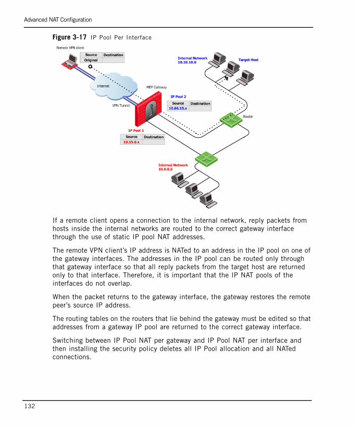
Advanced NAT Configuration
132
Figure 3-17 IP Pool Per Interface
If a remote client opens a connection to the internal network, reply packets from hosts inside the internal networks are routed to the correct gateway interface through the use of static IP pool NAT addresses.
The remote VPN client’s IP address is NATed to an address in the IP pool on one of the gateway interfaces. The addresses in the IP pool can be routed only through that gateway interface so that all reply packets from the target host are returned only to that interface. Therefore, it is important that the IP NAT pools of the interfaces do not overlap.
When the packet returns to the gateway interface, the gateway restores the remote peer’s source IP address.
The routing tables on the routers that lie behind the gateway must be edited so that addresses from a gateway IP pool are returned to the correct gateway interface.
Switching between IP Pool NAT per gateway and IP Pool NAT per interface and then installing the security policy deletes all IP Pool allocation and all NATed connections.
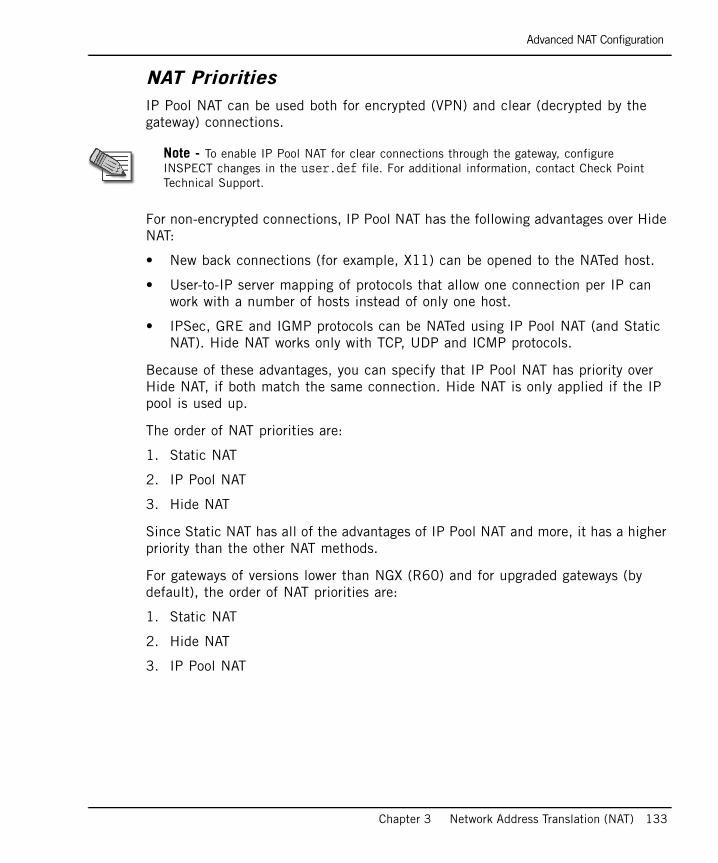
Advanced NAT Configuration
Chapter 3 Network Address Translation (NAT) 133
NAT PrioritiesIP Pool NAT can be used both for encrypted (VPN) and clear (decrypted by the gateway) connections.
For non-encrypted connections, IP Pool NAT has the following advantages over Hide NAT:
• New back connections (for example, X11) can be opened to the NATed host.
• User-to-IP server mapping of protocols that allow one connection per IP can work with a number of hosts instead of only one host.
• IPSec, GRE and IGMP protocols can be NATed using IP Pool NAT (and Static NAT). Hide NAT works only with TCP, UDP and ICMP protocols.
Because of these advantages, you can specify that IP Pool NAT has priority over Hide NAT, if both match the same connection. Hide NAT is only applied if the IP pool is used up.
The order of NAT priorities are:
1. Static NAT
2. IP Pool NAT
3. Hide NAT
Since Static NAT has all of the advantages of IP Pool NAT and more, it has a higher priority than the other NAT methods.
For gateways of versions lower than NGX (R60) and for upgraded gateways (by default), the order of NAT priorities are:
1. Static NAT
2. Hide NAT
3. IP Pool NAT
Note - To enable IP Pool NAT for clear connections through the gateway, configure INSPECT changes in the user.def file. For additional information, contact Check Point Technical Support.
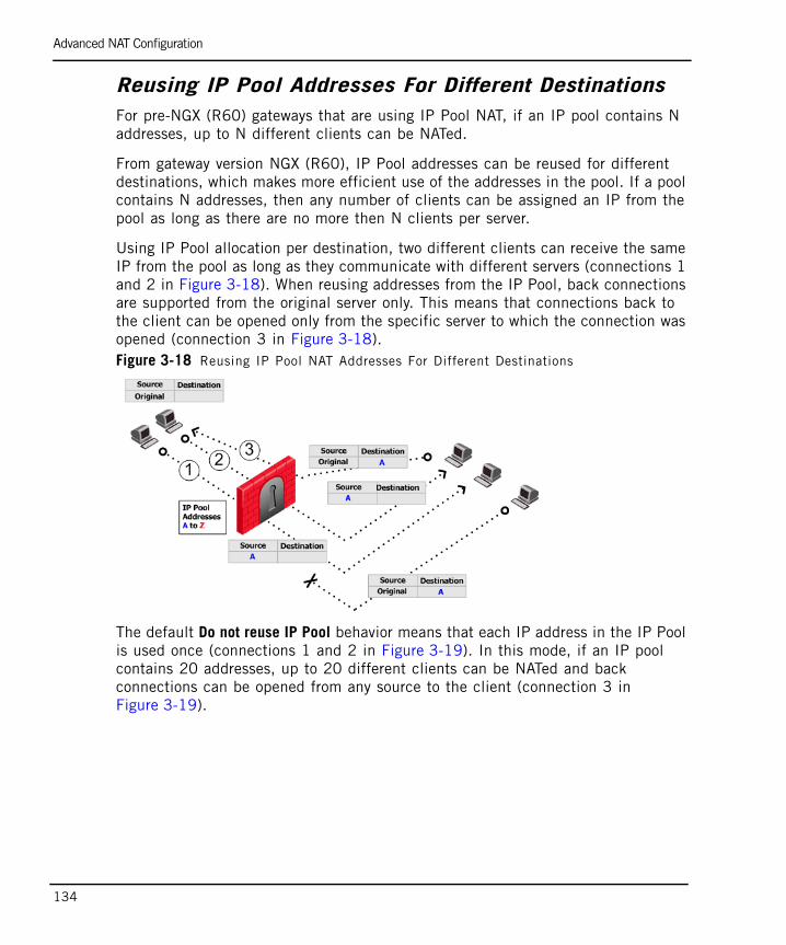
Advanced NAT Configuration
134
Reusing IP Pool Addresses For Different DestinationsFor pre-NGX (R60) gateways that are using IP Pool NAT, if an IP pool contains N addresses, up to N different clients can be NATed.
From gateway version NGX (R60), IP Pool addresses can be reused for different destinations, which makes more efficient use of the addresses in the pool. If a pool contains N addresses, then any number of clients can be assigned an IP from the pool as long as there are no more then N clients per server.
Using IP Pool allocation per destination, two different clients can receive the same IP from the pool as long as they communicate with different servers (connections 1 and 2 in Figure 3-18). When reusing addresses from the IP Pool, back connections are supported from the original server only. This means that connections back to the client can be opened only from the specific server to which the connection was opened (connection 3 in Figure 3-18). Figure 3-18 Reusing IP Pool NAT Addresses For Different Destinations
The default Do not reuse IP Pool behavior means that each IP address in the IP Pool is used once (connections 1 and 2 in Figure 3-19). In this mode, if an IP pool contains 20 addresses, up to 20 different clients can be NATed and back connections can be opened from any source to the client (connection 3 in Figure 3-19).
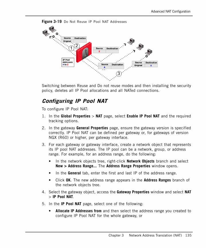
Advanced NAT Configuration
Chapter 3 Network Address Translation (NAT) 135
Figure 3-19 Do Not Reuse IP Pool NAT Addresses
Switching between Reuse and Do not reuse modes and then installing the security policy, deletes all IP Pool allocations and all NATed connections.
Configuring IP Pool NATTo configure IP Pool NAT:
1. In the Global Properties > NAT page, select Enable IP Pool NAT and the required tracking options.
2. In the gateway General Properties page, ensure the gateway version is specified correctly. IP Pool NAT can be defined per gateway or, for gateways of version NGX (R60) or higher, per gateway interface.
3. For each gateway or gateway interface, create a network object that represents its IP pool NAT addresses. The IP pool can be a network, group, or address range. For example, for an address range, do the following:
• In the network objects tree, right-click Network Objects branch and select New > Address Range... The Address Range Properties window opens.
• In the General tab, enter the first and last IP of the address range.
• Click OK. The new address range appears in the Address Ranges branch of the network objects tree.
4. Select the gateway object, access the Gateway Properties window and select NAT > IP Pool NAT.
5. In the IP Pool NAT page, select one of the following:
• Allocate IP Addresses from and then select the address range you created to configure IP Pool NAT for the whole gateway, or
Advanced NAT Configuration
136
• Define IP Pool addresses on gateway interfaces to configure IP Pool NAT per interface.
6. If required, select one or more of the following options:
• Use IP Pool NAT for VPN client connections
• Use IP Pool NAT for gateway to gateway connections
• Prefer IP Pool NAT over Hide NAT to specify that IP Pool NAT has priority over Hide NAT, if both match the same connection. Hide NAT is only applied if the IP pool is used up.
7. Click Advanced.
• Return unused addresses to IP Pool after: Addresses in the pool are reserved for t60 minutes (default), even if the user logs off. If the user disconnects from their ISP and then redials and reconnects, there will be two Pool NAT addresses in use for the user until the first address from the IP Pool times out. If users regularly lose their ISP connections, you may want to decrease the time-out to prevent the IP Pool from being depleted.
• Reuse IP addresses from the pool for different destinations: This is a good option unless you need to allow back connections to be opened to clients from any source, rather than just from the specific server to which the client originally opened the connection.
8. Click OK.
9. Edit the routing table of each internal router so that packets with an a IP address assigned from the NAT pool are routed to the appropriate gateway or, if using IP Pools per interface, the appropriate gateway interface.
IP Pool NAT for ClustersIP Pools for gateway clusters are configured in two places in SmartDashboard:
• In the gateway Cluster object NAT > IP Pool NAT page, select the connection scenario.
• In the Cluster member object IP Pool NAT page, define the IP Pool on the cluster member. A separate IP pool must be configured for each cluster member. It is not possible to define a separate IP Pool for each cluster member interface.

137
Chapter 4ISP Redundancy
In This Chapter
The Need for ISP Link Redundancy page 138
Solution for ISP Link Redundancy page 139
Considerations for ISP Link Redundancy page 149
Configuring ISP Link Redundancy page 150
The Need for ISP Link Redundancy
138
The Need for ISP Link RedundancyAs Internet access becomes increasingly critical to business success, the costs associated with the loss of connectivity become greater. To protect against network downtime, it makes sense to deploy redundant systems for mission critical Internet applications. Connecting to the Internet through more than one Internet Service Provider (ISP) provides that additional redundancy.
A number of solutions are available on the market that enable connections to multiple ISPs, however, these solutions often require expensive and specialized hardware and are difficult to set up and maintain. A simple solution is required that makes use of the existing boundary between the Internet and the organization, which is the firewalled gateway.
Solution for ISP Link Redundancy
Chapter 4 ISP Redundancy 139
Solution for ISP Link RedundancyIn This Section
ISP Redundancy OverviewISP Redundancy assures reliable Internet connectivity by allowing a single or clustered VPN-1 gateway to connect to the Internet through redundant Internet Service Provider (ISP) links. This feature is part of the standard VPN-1 installation and does not require costly new networking hardware or specialized knowledge to operate.
ISP Redundancy is supported on VPN-1 NG with Application Intelligence (R55) gateways or higher on the following platforms:
• Red Hat Linux 7.2 or higher
• SecurePlatform
• IPSO
ISP Redundancy monitors the ISP links and directs connections to the appropriate link, depending on the operating mode. Two modes are available: Load Sharing and Primary/Backup.
Figure 4-1 is a typical deployment with a single ISP link and redundant deployment with duplicate ISP links.
ISP Redundancy Overview page 139
ISP Redundancy Operational Modes page 140
Monitoring the ISP Links page 141
How ISP Redundancy Works page 141
ISP Redundancy Script page 143
Manually Changing the Link Status (fw isp_link) page 143
ISP Redundancy Deployments page 144
ISP Redundancy and VPNs page 147

Solution for ISP Link Redundancy
140
Figure 4-1 ISP Link Redundancy
ISP Redundancy Operational ModesThe following ISP Redundancy modes control the behavior of outgoing connections from clients in the internal networks to the Internet:
• Primary/Backup: Connects to an ISP through the primary link and switches to a backup ISP when the primary ISP link fails. When the primary link is restored, new outgoing connections are assigned to it, while existing connections are maintained over the backup link until they are complete.
• Load Sharing: Connects to both ISPs while distributing the load of outgoing connections between the ISPs. New connections are randomly assigned to a link. If a link fails, all new outgoing connections are directed to the active link.
Incoming connections (from the Internet to application servers in the DMZ or internal networks) also benefit from the high availability of the two ISP links because VPN-1 returns packets using the same ISP Link through which the connection was initiated.
Furthermore, in Load Sharing mode, incoming connections can reach the application servers through either ISP link because VPN-1 can answer DNS requests for the IP address of internal servers with addresses from both ISPs by alternating their order.

Solution for ISP Link Redundancy
Chapter 4 ISP Redundancy 141
Monitoring the ISP LinksISP Redundancy monitors the status of the ISP links and directs outgoing connections to the appropriate link.
To monitor the status of the link, VPN-1 checks whether or not the interface is running and if the cable is plugged in. The next hop router is monitored automatically.
Another way of monitoring the status of the ISP link is for the administrator to configure a list of hosts that must answer ICMP echo requests (pings) in order for the ISP link to be considered active. If one of the hosts fails to return ICMP replies, the link is considered to be down. You may opt to include hosts such as an ISP Web server or some other host on the Internet.
The status of the ISP links is reported by SmartView Monitor in the Firewall section.
How ISP Redundancy WorksBoth outgoing connections, from behind the VPN-1 gateway towards the Internet, and incoming connections, from the Internet, benefit from the existence of duplicate links.
Outgoing ConnectionsIn Load Sharing mode, outgoing traffic that exits the VPN-1 gateway on its way to the Internet is distributed between the ISP Links. In Primary/Backup mode, outgoing traffic uses an active primary link.
Hide NAT is used to change the source address of outgoing packets to the address of the interface through which the packet leaves the VPN-1 gateway. This allows return packets to be automatically routed through the same ISP link because their destination address is the address of the correct link. Hide NAT is configured by the administrator.
Incoming ConnectionsFor external users to make incoming connections, the administrator must give each application server two routable IP addresses, one for each ISP. The administrator must also configure Static NAT to translate the routable addresses to the real server address.
If the servers handle different services (for example, HTTP and FTP), you can use NAT to employ only two routable IP addresses for all the publicly available servers.
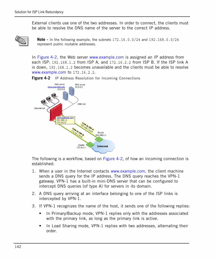
Solution for ISP Link Redundancy
142
External clients use one of the two addresses. In order to connect, the clients must be able to resolve the DNS name of the server to the correct IP address.
In Figure 4-2, the Web server www.example.com is assigned an IP address from each ISP: 192.168.1.2 from ISP A, and 172.16.2.2 from ISP B. If the ISP link A is down, 192.168.1.2 becomes unavailable and the clients must be able to resolve www.example.com to 172.16.2.2.Figure 4-2 IP Address Resolution for Incoming Connections
The following is a workflow, based on Figure 4-2, of how an incoming connection is established:
1. When a user in the Internet contacts www.example.com, the client machine sends a DNS query for the IP address. The DNS query reaches the VPN-1 gateway. VPN-1 has a built-in mini-DNS server that can be configured to intercept DNS queries (of type A) for servers in its domain.
2. A DNS query arriving at an interface belonging to one of the ISP links is intercepted by VPN-1.
3. If VPN-1 recognizes the name of the host, it sends one of the following replies:
• In Primary/Backup mode, VPN-1 replies only with the addresses associated with the primary link, as long as the primary link is active.
• In Load Sharing mode, VPN-1 replies with two addresses, alternating their order.
Note - In the following example, the subnets 172.16.0.0/24 and 192.168.0.0/24 represent public routable addresses.
Solution for ISP Link Redundancy
Chapter 4 ISP Redundancy 143
4. If VPN-1 is unable to handle DNS requests (for example, it may not recognize the host name,), it passes the DNS query to its original destination or the DNS server of the domain example.com.
5. When the external client receives the reply to its DNS query, it opens a connection. Once the packets reach the gateway, VPN-1 uses Static NAT to translate the destination address 192.168.1.2 or 172.16.2.2 to the real server address 10.0.0.2.
6. VPN-1 routes reply packets from the server to the client through the same ISP link that was used to initiate the connection.
ISP Redundancy ScriptWhenever VPN-1 starts or an ISP link state changes, a script is run. Depending on whether the ISP link is up or down, this script automatically changes the default route of the VPN-1 gateway.
If one of the ISP links is a dialup interface, you can manually edit the ISP Redundancy script to make the VPN-1 change the state of the dialup interface when the ISP links state changes or when the VPN-1 starts.
The script can also be configured to perform other actions, for example, to issue a SAM command to block certain traffic when the primary link is down in order to decrease the traffic load on the link.
The name and location of the ISP Redundancy script is $FWDIR/bin/cpisp_update.
Manually Changing the Link Status (fw isp_link)The fw isp_link command is used to configure the ISP link on VPN-1 to Down or Up and is helpful:
• When testing your configuration.
• When you know the ISP link is down, but VPN-1 thinks it is up. In this case, use the command to bring the link back up when the link actually becomes available.
This command can be executed locally on the gateway or remotely from the SmartCenter server. When executed from the SmartCenter server, you must provide the fw isp_link [target] link-name up|down target argument, where <target> is the name of the gateway and <link-name> is the name of the ISP link, as defined in the ISP Redundancy page of the gateway or gateway Cluster object.

Solution for ISP Link Redundancy
144
ISP Redundancy DeploymentsA number of deployments are supported. For additional information on each deployment type, refer to “Considerations for ISP Link Redundancy” on page 149.
Two External InterfacesThe easiest way to connect to two ISPs is to connect each VPN-1 gateway interface to a different ISP through a LAN (Figure 4-3). The next hop routers are either at the boundary of the organization or at the ISP.Figure 4-3 Two ISPs Connected to Different External VPN-1 Gateway Interfaces
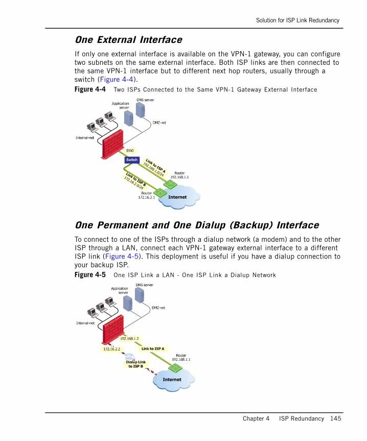
Solution for ISP Link Redundancy
Chapter 4 ISP Redundancy 145
One External InterfaceIf only one external interface is available on the VPN-1 gateway, you can configure two subnets on the same external interface. Both ISP links are then connected to the same VPN-1 interface but to different next hop routers, usually through a switch (Figure 4-4). Figure 4-4 Two ISPs Connected to the Same VPN-1 Gateway External Interface
One Permanent and One Dialup (Backup) InterfaceTo connect to one of the ISPs through a dialup network (a modem) and to the other ISP through a LAN, connect each VPN-1 gateway external interface to a different ISP link (Figure 4-5). This deployment is useful if you have a dialup connection to your backup ISP.Figure 4-5 One ISP Link a LAN - One ISP Link a Dialup Network

Solution for ISP Link Redundancy
146
Gateway Cluster ConnectionIf you have a ClusterXL gateway cluster, connect each cluster member to both ISPs through a LAN using two interfaces (Figure 4-6).
Configure ClusterXL in the usual way, however, ensure that the member interfaces are on the same subnet as the cluster external interfaces (for additional information, refer to the ClusterXL Administration Guide). Figure 4-6 Both ISP Links are LANs Connected to a Gateway Cluster
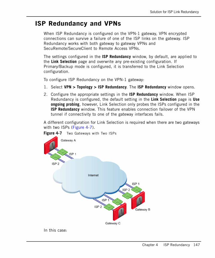
Solution for ISP Link Redundancy
Chapter 4 ISP Redundancy 147
ISP Redundancy and VPNsWhen ISP Redundancy is configured on the VPN-1 gateway, VPN encrypted connections can survive a failure of one of the ISP links on the gateway. ISP Redundancy works with both gateway to gateway VPNs and SecuRemote/SecureClient to Remote Access VPNs.
The settings configured in the ISP Redundancy window, by default, are applied to the Link Selection page and overwrite any pre-existing configuration. If Primary/Backup mode is configured, it is transferred to the Link Selection configuration.
To configure ISP Redundancy on the VPN-1 gateway:
1. Select VPN > Topology > ISP Redundancy. The ISP Redundancy window opens.
2. Configure the appropriate settings in the ISP Redundancy window. When ISP Redundancy is configured, the default setting in the Link Selection page is Use ongoing probing, however, Link Selection only probes the ISPs configured in the ISP Redundancy window. This feature enables connection failover of the VPN tunnel if connectivity to one of the gateway interfaces fails.
A different configuration for Link Selection is required when there are two gateways with two ISPs (Figure 4-7).Figure 4-7 Two Gateways with Two ISPs
In this case:

Solution for ISP Link Redundancy
148
• Gateways A, B, and C have two ISPs.
• ISP Redundancy is configured on gateway A.
• Gateway A should use ISP 1 to connect to gateway B and ISP 2 to connect to gateway C. If one of the ISPs becomes unavailable, the other ISP should be used.
For additional configuration information, refer to the “Link Selection” chapter of the VPN Administration Guide.
ISP Redundancy and Third-Party VPNsThe ability of a third-party VPN device to detect an ISP link failure depends on the third-party device implementation. The failure of an ISP link could lead to a VPN failure for the following reasons:
1. The third-party device may not recognize incoming encrypted traffic from the secondary link as coming from the gateway.
2. The third-party device may be unable to detect an ISP link failure and therefore may continue encrypting traffic to the failed link.
Considerations for ISP Link Redundancy
Chapter 4 ISP Redundancy 149
Considerations for ISP Link Redundancy
Choosing the DeploymentThe choice of deployment that best suits your organization’s needs is normally evident. The following are some recommendations:
• The simplest configuration is to use a different interface for each ISP link, as shown in Figure 4-3.
• If only one external interface is available on the VPN-1 gateway, you can connect both ISPs to the same interface by defining two subnets, one for each ISP on the same interface, as shown in Figure 4-4 .
• If one of the ISP links is a dialup network (modem connection) that is used for backup, use the deployment shown in Figure 4-5 and select the Primary/Backup mode of operation.
• If the ISP links are connected to a VPN-1 gateway cluster, use the deployment shown in Figure 4-6.
Choosing the Redundancy ModeIf both ISPs are basically the same, use Load Sharing mode to ensure that you are making the best use of both ISPs.
You may prefer to use one of your two ISPs that is more cost-effective in terms of price and reliability. In that case, use Primary/Backup mode and set the more cost-effective ISP as the Primary ISP link.
Configuring ISP Link Redundancy
150
Configuring ISP Link RedundancyIn This Section
Introduction to ISP Link Redundancy ConfigurationThe following ISP Redundancy configuration allows outgoing connections from behind the VPN-1 gateway to the Internet and incoming connections from the Internet to the networks behind the VPN-1 gateway.
Registering the Domain and Obtaining IP AddressesThe VPN-1 gateway, or a DNS server behind it, must respond to DNS queries and resolve IP addresses that belong to publicly accessible servers in the DMZ (or another internal network). It is not necessary to have an actual DNS server because the VPN-1 gateway can be configured to intercept the DNS queries.
To register the domain and obtain IP addresses:
1. Obtain one routable IP address from each ISP for the DNS server or for the VPN-1 gateway that intercepts DNS queries. If routable IP addresses are not available, make the DNS server accessible from the Internet using manual NAT (step 15).
2. Register your domain (for example, example.com) with both ISPs.
3. Inform both ISPs of the two addresses of the DNS server that respond to DNS queries for the example.com domain.
Introduction to ISP Link Redundancy Configuration page 150
Registering the Domain and Obtaining IP Addresses page 150
DNS Server Configuration for Incoming Connections page 151
Dialup Link Setup for Incoming Connections page 152
SmartDashboard Configuration page 152
Configuring the Default Route for the ISP Redundancy Gateway page 154
Note - For advanced configuration options, refer to SecureKnowledge solution sk23630 at https://secureknowledge.checkpoint.com/ (your username and password are required). Note - In the following configuration examples, the subnets 192.168.1.0/24 and 172.16.2.0/24 represent public routable addresses.
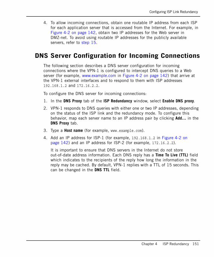
Configuring ISP Link Redundancy
Chapter 4 ISP Redundancy 151
4. To allow incoming connections, obtain one routable IP address from each ISP for each application server that is accessed from the Internet. For example, in Figure 4-2 on page 142, obtain two IP addresses for the Web server in DMZ-net. To avoid using routable IP addresses for the publicly available servers, refer to step 15.
DNS Server Configuration for Incoming ConnectionsThe following section describes a DNS server configuration for incoming connections where the VPN-1 is configured to intercept DNS queries to a Web server (for example, www.example.com in Figure 4-2 on page 142) that arrive at the VPN-1 external interfaces and to respond to them with ISP addresses 192.168.1.2 and 172.16.2.2.
To configure the DNS server for incoming connections:
1. In the DNS Proxy tab of the ISP Redundancy window, select Enable DNS proxy.
2. VPN-1 responds to DNS queries with either one or two IP addresses, depending on the status of the ISP link and the redundancy mode. To configure this behavior, map each server name to an IP address pair by clicking Add… in the DNS Proxy tab.
3. Type a Host name (for example, www.example.com).
4. Add an IP address for ISP-1 (for example, 192.168.1.2 in Figure 4-2 on page 142) and an IP address for ISP-2 (for example, 172.16.2.2).
It is important to ensure that DNS servers in the Internet do not store out-of-date address information. Each DNS reply has a Time To Live (TTL) field which indicates to the recipients of the reply how long the information in the reply may be cached. By default, VPN-1 replies with a TTL of 15 seconds. This can be changed in the DNS TTL field.
Configuring ISP Link Redundancy
152
Dialup Link Setup for Incoming ConnectionsTo configure a dialup link for incoming connections:
1. If one of the ISP links is a dialup network, edit the ISP Redundancy Script located in $FWDIR/bin/cpisp_update.
2. In the script, use the Linux or SecurePlatform operating system command to bring up or to take down the dialup interface.
3. You can connect SecurePlatform to ISPs that provide xDSL services using PPPoE or PPTP xDSL modems. If using one of these connections, in the PPPoE or PPTP configuration of SecurePlatform, clear the Use Peer Gateway option.
SmartDashboard ConfigurationTo configure SmartDashboard:
1. Define a Security Rule Base rule that accepts DNS traffic through the VPN-1 gateway using the domain_udp service.
2. In the Check Point Gateway window of the Topology page, define the VPN-1 interfaces leading to the ISPs.
3. Select Topology > ISP Redundancy and then the Support ISP Redundancy option.
4. Perform either Automatic ISP Link Configuration (follow step 5 to step 8) or Manual ISP Link Configuration (follow step 9 to step 13). Automatic configuration only works if there are exactly two external interfaces defined in the Topology page (it does not work for gateway cluster objects).
Automatic ISP Link Configuration
5. Click Automatic ISP Links configuration to configure the ISP links based on information taken from the routing table of the gateway and the Topology page of the gateway object.
6. To work in Primary/Backup mode, do the following:
a. In the Redundancy Mode section, select Primary/Backup.
b. Select the link and then Edit to define the link you want to be primary.
c. In the General tab of the ISP Link Properties window, select Primary ISP.
7. Examine the automatically configured ISP Links configuration for correctness.
8. Continue to step 14.
Configuring ISP Link Redundancy
Chapter 4 ISP Redundancy 153
Manual ISP Link Configuration
9. In the Redundancy Mode section, select Load Sharing or Primary/Backup.
10. Click Add to define each of the ISP links.
11. In the General tab of the ISP Link Properties window, configure the following:
a. Name the ISP link and select the Interface leading to the ISP.
b. Specify the Next Hop IP Address by clicking Get from routing table. If the ISP link is a dialup connection, leave the Next Hop IP Address field blank.
In Figure 4-3 on page 144, the next hop router on the way to ISP A has the IP address 192.168.1.1 and the next hop router on the way to ISP B has the IP address 172.16.2.1.
c. In Primary/Backup mode, define whether the ISP link is Primary.
12. Define a list of hosts to be monitored to verify that the link is operational. To specify the hosts, select the Advanced tab of the ISP Link Properties window and then Add to add the hosts to the list of Selected hosts.
13. Define Tracking by selecting an option for both ISP failure and ISP recovery.
Allowing Incoming and Outgoing Connections
14. To allow outgoing connections through both ISP links, define automatic Hide NAT on network objects that initiate the outgoing connections. Using the example shown in Figure 4-2 on page 142, configure the following:
a. Edit the internal_net object.
b. In the General tab of the Network Properties window, select Add Automatic Address Translation Rules.
c. Select the Hide Translation Method and then the Hide behind Gateway option.
15. To allow incoming connections through both ISP links to the application servers and the DNS server, define manual Static NAT rules.
If you have only one routable IP address from each ISP and those addresses belong to the VPN-1 gateway, you can allow specific services for specific servers. Using the example shown in Figure 4-2 on page 142, define the NAT
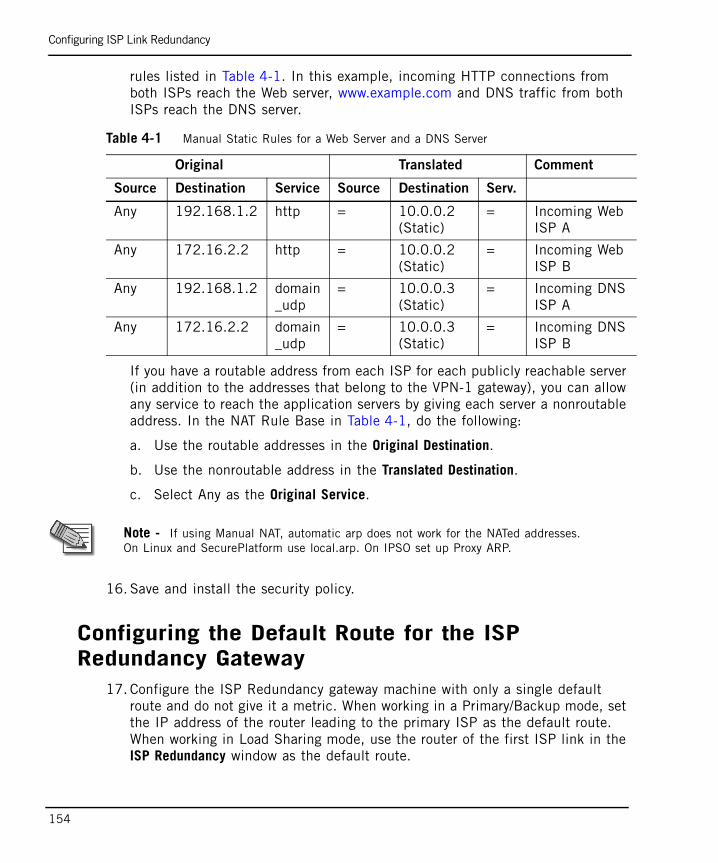
Configuring ISP Link Redundancy
154
rules listed in Table 4-1. In this example, incoming HTTP connections from both ISPs reach the Web server, www.example.com and DNS traffic from both ISPs reach the DNS server.
If you have a routable address from each ISP for each publicly reachable server (in addition to the addresses that belong to the VPN-1 gateway), you can allow any service to reach the application servers by giving each server a nonroutable address. In the NAT Rule Base in Table 4-1, do the following:
a. Use the routable addresses in the Original Destination.
b. Use the nonroutable address in the Translated Destination.
c. Select Any as the Original Service.
16. Save and install the security policy.
Configuring the Default Route for the ISP Redundancy Gateway
17. Configure the ISP Redundancy gateway machine with only a single default route and do not give it a metric. When working in a Primary/Backup mode, set the IP address of the router leading to the primary ISP as the default route. When working in Load Sharing mode, use the router of the first ISP link in the ISP Redundancy window as the default route.
Table 4-1 Manual Static Rules for a Web Server and a DNS Server
Original Translated Comment
Source Destination Service Source Destination Serv.
Any 192.168.1.2 http = 10.0.0.2 (Static)
= Incoming WebISP A
Any 172.16.2.2 http = 10.0.0.2 (Static)
= Incoming WebISP B
Any 192.168.1.2 domain_udp
= 10.0.0.3 (Static)
= Incoming DNSISP A
Any 172.16.2.2 domain_udp
= 10.0.0.3 (Static)
= Incoming DNSISP B
Note - If using Manual NAT, automatic arp does not work for the NATed addresses. On Linux and SecurePlatform use local.arp. On IPSO set up Proxy ARP.

Configuring ISP Link Redundancy
Chapter 4 ISP Redundancy 155
When an ISP link fails, the default route of the gateway is automatically changed by means of the ISP Redundancy script. When the link is up again, the original default route is reinstated.

Configuring ISP Link Redundancy
156
157
Chapter 5ConnectControl - Server Load Balancing
In This Chapter
The Need for Server Load Balancing page 158
ConnectControl Solution for Server Load Balancing page 159
Configuring ConnectControl page 167
The Need for Server Load Balancing
158
The Need for Server Load BalancingWhile Check Point offers optimal performance for single server deployment, there are several disadvantages to relying on a single server to host an application. While a server's capabilities can often be expanded with additional processors and RAM, in many cases a lone machine cannot handle the traffic volume, which results in poor response times and connection time outs. In addition, server maintenance and other unplanned downtimes are problematic in a single server environment. Sharing network traffic intelligently among multiple servers can shorten response times and reduce the risk to the application by the failure of any one machine.
ConnectControl Solution for Server Load Balancing
Chapter 5 ConnectControl - Server Load Balancing 159
ConnectControl Solution for Server Load Balancing
In This Section
Introduction to ConnectControlConnectControl is Check Point’s solution for server load balancing. ConnectControl distributes network traffic among a number of servers, which reduces the load on a single machine and thereby improves network response time and provides high availability. In addition to the performance benefits, spreading the load over multiple machines creates redundancy for your application and reduces the risk of downtime.
Load-balanced servers are represented by a single virtual IP address, so clients are unaware that more than one server is serving their requests. This is accomplished using a Logical server, which is a network object defined in SmartDashboard that represents a group of physical servers. The Logical server fields service requests for the load-balanced application and directs them to the appropriate physical server.
ConnectControl runs on the gateway and does not impose any additional memory or processing requirements. It continuously checks the availability of each server and if a server fails or is unreachable, ConnectControl stops directing connections to that server until it becomes available.
Introduction to ConnectControl page 159
Load-Balancing Methods page 160
ConnectControl Packet Flow page 161
Logical Server Types page 161
Persistent Server Mode page 164
Server Availability page 166
Load Measuring page 166

ConnectControl Solution for Server Load Balancing
160
Load-Balancing Methods ConnectControl distributes network traffic to load-balanced servers according to predefined balancing methods, which include:
• Server Load: Measures the load on each server to determine which server has the most available resources to service a request. Each server in the group runs a load measuring agent that automatically reports the current system load to the ConnectControl module on the VPN-1 gateway. Server Load is a good choice if your servers run other demanding applications in addition to supporting your load-balanced application. For additional information, refer to “Load Measuring” on page 166.
• Round Trip: Ensures that incoming requests are handled by the server with the fastest response time. ConnectControl ascertains the response times of the servers in the group at a user-defined interval, whereupon the gateway executes a series of ICMP echo requests (pings) and reports which server has the shortest average round trip time. ConnectControl then directs the service request to that server. The round trip method is a good choice if there are large variations in the traffic load on your network or when load balancing over WAN connections.
• Round Robin: Assigns service requests to the next server in the sequence. The round robin method provides optimal load balancing when the load balanced servers all have similar RAM and CPU and are located on the same segment.
• Random: Assigns service requests to servers at random. The random method provides optimal load balancing when the load-balanced servers all have similar RAM and CPU and are located on the same segment.
• Domain: Directs service requests based on domain name.
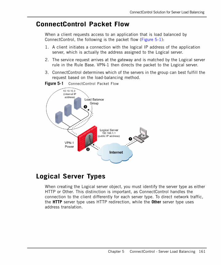
ConnectControl Solution for Server Load Balancing
Chapter 5 ConnectControl - Server Load Balancing 161
ConnectControl Packet FlowWhen a client requests access to an application that is load balanced by ConnectControl, the following is the packet flow (Figure 5-1):
1. A client initiates a connection with the logical IP address of the application server, which is actually the address assigned to the Logical server.
2. The service request arrives at the gateway and is matched by the Logical server rule in the Rule Base. VPN-1 then directs the packet to the Logical server.
3. ConnectControl determines which of the servers in the group can best fulfill the request based on the load-balancing method.
Figure 5-1 ConnectControl Packet Flow
Logical Server TypesWhen creating the Logical server object, you must identify the server type as either HTTP or Other. This distinction is important, as ConnectControl handles the connection to the client differently for each server type. To direct network traffic, the HTTP server type uses HTTP redirection, while the Other server type uses address translation.
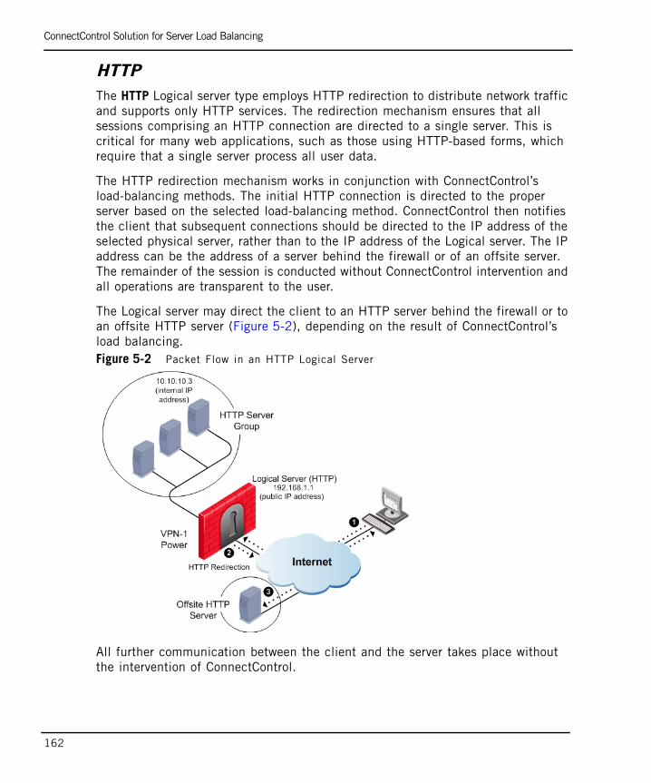
ConnectControl Solution for Server Load Balancing
162
HTTPThe HTTP Logical server type employs HTTP redirection to distribute network traffic and supports only HTTP services. The redirection mechanism ensures that all sessions comprising an HTTP connection are directed to a single server. This is critical for many web applications, such as those using HTTP-based forms, which require that a single server process all user data.
The HTTP redirection mechanism works in conjunction with ConnectControl’s load-balancing methods. The initial HTTP connection is directed to the proper server based on the selected load-balancing method. ConnectControl then notifies the client that subsequent connections should be directed to the IP address of the selected physical server, rather than to the IP address of the Logical server. The IP address can be the address of a server behind the firewall or of an offsite server. The remainder of the session is conducted without ConnectControl intervention and all operations are transparent to the user.
The Logical server may direct the client to an HTTP server behind the firewall or to an offsite HTTP server (Figure 5-2), depending on the result of ConnectControl’s load balancing. Figure 5-2 Packet Flow in an HTTP Logical Server
All further communication between the client and the server takes place without the intervention of ConnectControl.
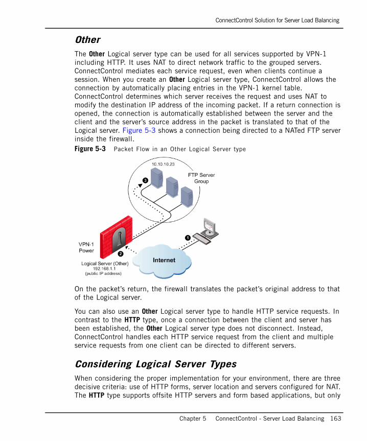
ConnectControl Solution for Server Load Balancing
Chapter 5 ConnectControl - Server Load Balancing 163
OtherThe Other Logical server type can be used for all services supported by VPN-1 including HTTP. It uses NAT to direct network traffic to the grouped servers. ConnectControl mediates each service request, even when clients continue a session. When you create an Other Logical server type, ConnectControl allows the connection by automatically placing entries in the VPN-1 kernel table. ConnectControl determines which server receives the request and uses NAT to modify the destination IP address of the incoming packet. If a return connection is opened, the connection is automatically established between the server and the client and the server’s source address in the packet is translated to that of the Logical server. Figure 5-3 shows a connection being directed to a NATed FTP server inside the firewall. Figure 5-3 Packet Flow in an Other Logical Server type
On the packet’s return, the firewall translates the packet’s original address to that of the Logical server.
You can also use an Other Logical server type to handle HTTP service requests. In contrast to the HTTP type, once a connection between the client and server has been established, the Other Logical server type does not disconnect. Instead, ConnectControl handles each HTTP service request from the client and multiple service requests from one client can be directed to different servers.
Considering Logical Server TypesWhen considering the proper implementation for your environment, there are three decisive criteria: use of HTTP forms, server location and servers configured for NAT. The HTTP type supports offsite HTTP servers and form based applications, but only
ConnectControl Solution for Server Load Balancing
164
works with the HTTP protocol. The Other type supports all protocols and may provide the most effectively balanced load, but requires servers to be NATed by the gateway.
Persistent Server ModePersistent server mode is a ConnectControl feature that maintains a client’s connection to the server to which it was first directed (for additional information, refer to “Persistent Server Timeout” on page 165). When using this feature, you must decide whether the persistency is by server or by service.
Persistency By ServerPersistency by server is useful for certain types of HTTP applications, such as forms support, for example, in a load-balanced environment of three Web servers (Figure 5-4). When Persistency by server is enabled, ConnectControl directs an HTTP client to a specific server and each subsequent request by the client is directed to the same server. This mode allows clients to fill out forms without the data loss that occurs if separate service requests are directed to different servers. If you support forms, enable Persistent server mode (the default setting) and the Persistency by server option.
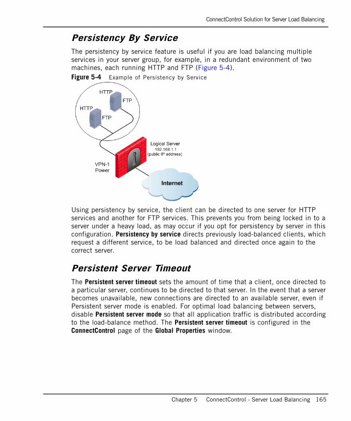
ConnectControl Solution for Server Load Balancing
Chapter 5 ConnectControl - Server Load Balancing 165
Persistency By ServiceThe persistency by service feature is useful if you are load balancing multiple services in your server group, for example, in a redundant environment of two machines, each running HTTP and FTP (Figure 5-4). Figure 5-4 Example of Persistency by Service
Using persistency by service, the client can be directed to one server for HTTP services and another for FTP services. This prevents you from being locked in to a server under a heavy load, as may occur if you opt for persistency by server in this configuration. Persistency by service directs previously load-balanced clients, which request a different service, to be load balanced and directed once again to the correct server.
Persistent Server TimeoutThe Persistent server timeout sets the amount of time that a client, once directed to a particular server, continues to be directed to that server. In the event that a server becomes unavailable, new connections are directed to an available server, even if Persistent server mode is enabled. For optimal load balancing between servers, disable Persistent server mode so that all application traffic is distributed according to the load-balance method. The Persistent server timeout is configured in the ConnectControl page of the Global Properties window.
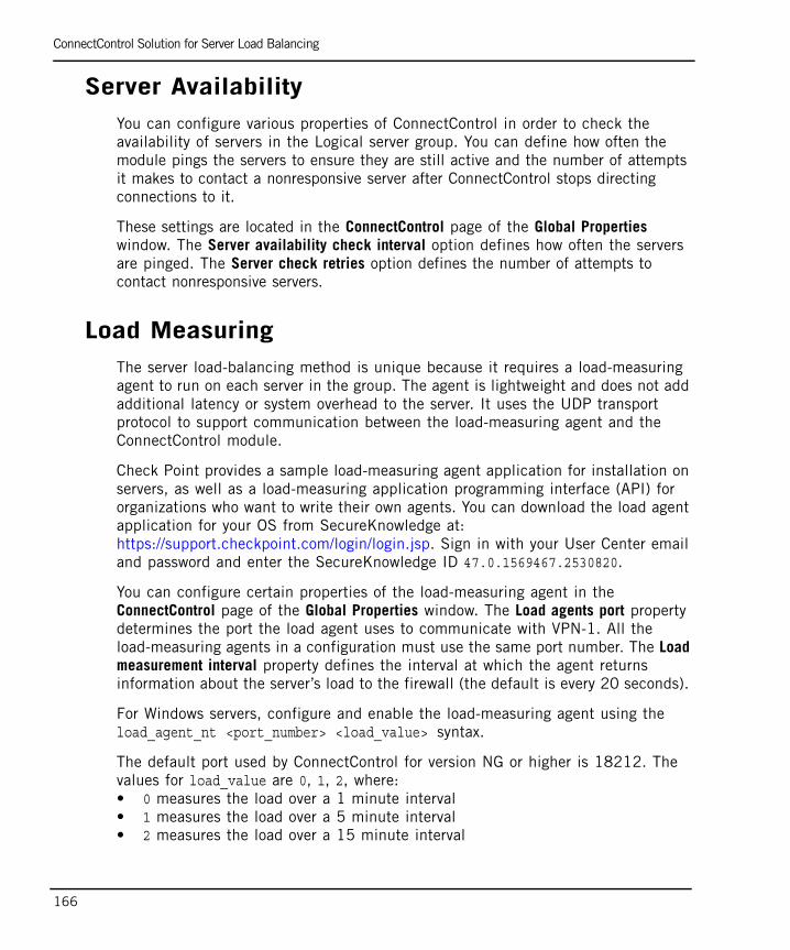
ConnectControl Solution for Server Load Balancing
166
Server AvailabilityYou can configure various properties of ConnectControl in order to check the availability of servers in the Logical server group. You can define how often the module pings the servers to ensure they are still active and the number of attempts it makes to contact a nonresponsive server after ConnectControl stops directing connections to it.
These settings are located in the ConnectControl page of the Global Properties window. The Server availability check interval option defines how often the servers are pinged. The Server check retries option defines the number of attempts to contact nonresponsive servers.
Load MeasuringThe server load-balancing method is unique because it requires a load-measuring agent to run on each server in the group. The agent is lightweight and does not add additional latency or system overhead to the server. It uses the UDP transport protocol to support communication between the load-measuring agent and the ConnectControl module.
Check Point provides a sample load-measuring agent application for installation on servers, as well as a load-measuring application programming interface (API) for organizations who want to write their own agents. You can download the load agent application for your OS from SecureKnowledge at: https://support.checkpoint.com/login/login.jsp. Sign in with your User Center email and password and enter the SecureKnowledge ID 47.0.1569467.2530820.
You can configure certain properties of the load-measuring agent in the ConnectControl page of the Global Properties window. The Load agents port property determines the port the load agent uses to communicate with VPN-1. All the load-measuring agents in a configuration must use the same port number. The Load measurement interval property defines the interval at which the agent returns information about the server’s load to the firewall (the default is every 20 seconds).
For Windows servers, configure and enable the load-measuring agent using the load_agent_nt <port_number> <load_value> syntax.
The default port used by ConnectControl for version NG or higher is 18212. The values for load_value are 0, 1, 2, where: • 0 measures the load over a 1 minute interval• 1 measures the load over a 5 minute interval• 2 measures the load over a 15 minute interval
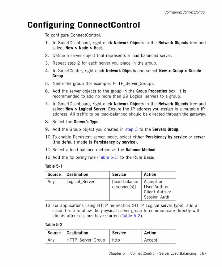
Configuring ConnectControl
Chapter 5 ConnectControl - Server Load Balancing 167
Configuring ConnectControlTo configure ConnectControl:
1. In SmartDashboard, right-click Network Objects in the Network Objects tree and select New > Node > Host.
2. Define a server object that represents a load-balanced server.
3. Repeat step 2 for each server you place in the group.
4. In SmartCenter, right-click Network Objects and select New > Group > Simple Group.
5. Name the group (for example, HTTP_Server_Group).
6. Add the server objects to the group in the Group Properties box. It is recommended to add no more than 29 Logical servers to a group.
7. In SmartDashboard, right-click Network Objects in the Network Objects tree and select New > Logical Server. Ensure the IP address you assign is a routable IP address. All traffic to be load-balanced should be directed through the gateway.
8. Select the Server’s Type.
9. Add the Group object you created in step 3 to the Servers Group.
10. To enable Persistent server mode, select either Persistency by service or server (the default mode is Persistency by service).
11. Select a load-balance method as the Balance Method.
12. Add the following rule (Table 5-1) to the Rule Base:
13. For applications using HTTP redirection (HTTP Logical server type), add a second rule to allow the physical server group to communicate directly with clients after sessions have started (Table 5-2).
Table 5-1
Source Destination Service Action
Any Logical_Server [load-balanced service(s)]
Accept or User Auth or Client Auth or Session Auth
Table 5-2
Source Destination Service Action
Any HTTP_Server_Group http Accept
Configuring ConnectControl
168
14. From the Policy menu, select Global Properties > ConnectControl. Review the default settings and adjust according to your implementation. The following options are available:
• Servers Availability: Manages how often ConnectControl ensures that the load-balanced servers are running and responding to service requests and how many times ConnectControl attempts to contact a server before ceasing to direct traffic to it. The Server availability check interval option default value is 20 seconds. The Server check retries option default value is 3 times.
• Servers Persistency: Defines the amount of time that a client, once directed to a particular server, directs traffic to it. The Persistent server timeout option default value is 1800 seconds.
• Servers Load Balancing: Manages how often the load measuring agents (if employed) report their load status to ConnectControl and the port from which they communicate with ConnectControl. The Load agents port option default value is 18212. The Load measurement interval default value is 20 seconds.

169
Chapter 6Bridge Mode
In This Chapter
Introduction to Bridge Mode page 170
Configuring Bridge Mode page 172
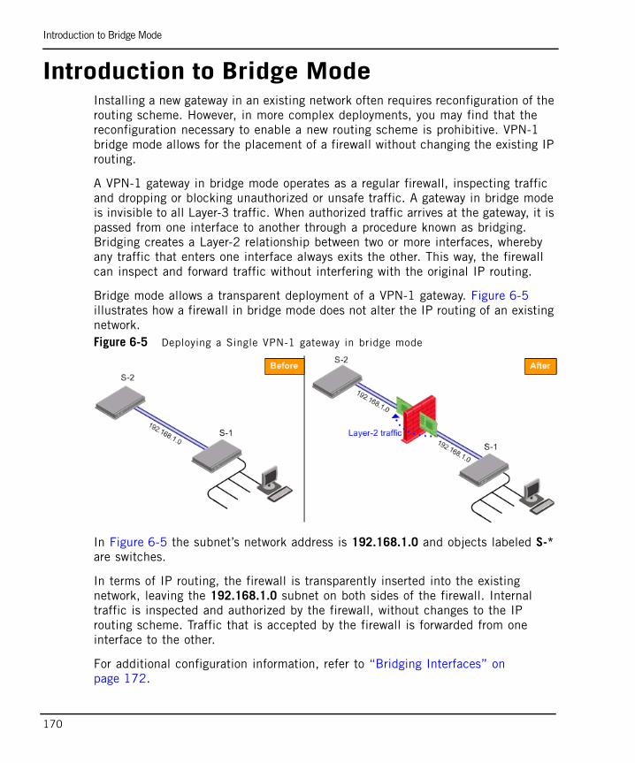
Introduction to Bridge Mode
170
Introduction to Bridge ModeInstalling a new gateway in an existing network often requires reconfiguration of the routing scheme. However, in more complex deployments, you may find that the reconfiguration necessary to enable a new routing scheme is prohibitive. VPN-1 bridge mode allows for the placement of a firewall without changing the existing IP routing.
A VPN-1 gateway in bridge mode operates as a regular firewall, inspecting traffic and dropping or blocking unauthorized or unsafe traffic. A gateway in bridge mode is invisible to all Layer-3 traffic. When authorized traffic arrives at the gateway, it is passed from one interface to another through a procedure known as bridging. Bridging creates a Layer-2 relationship between two or more interfaces, whereby any traffic that enters one interface always exits the other. This way, the firewall can inspect and forward traffic without interfering with the original IP routing.
Bridge mode allows a transparent deployment of a VPN-1 gateway. Figure 6-5 illustrates how a firewall in bridge mode does not alter the IP routing of an existing network.Figure 6-5 Deploying a Single VPN-1 gateway in bridge mode
In Figure 6-5 the subnet’s network address is 192.168.1.0 and objects labeled S-* are switches.
In terms of IP routing, the firewall is transparently inserted into the existing network, leaving the 192.168.1.0 subnet on both sides of the firewall. Internal traffic is inspected and authorized by the firewall, without changes to the IP routing scheme. Traffic that is accepted by the firewall is forwarded from one interface to the other.
For additional configuration information, refer to “Bridging Interfaces” on page 172.

Limitations in Bridge Mode
Chapter 6 Bridge Mode 171
Limitations in Bridge Mode• Each bridge supports a pair of interfaces only.
• Cluster configurations are not supported.
• Bridge mode is supported on the Check Point operating system SecurePlatform.
Managing a Gateway in Bridge ModeIn order to manage a gateway in bridge mode, an interface with an IP address is required. It is important to configure a separate, routed interface for this purpose.
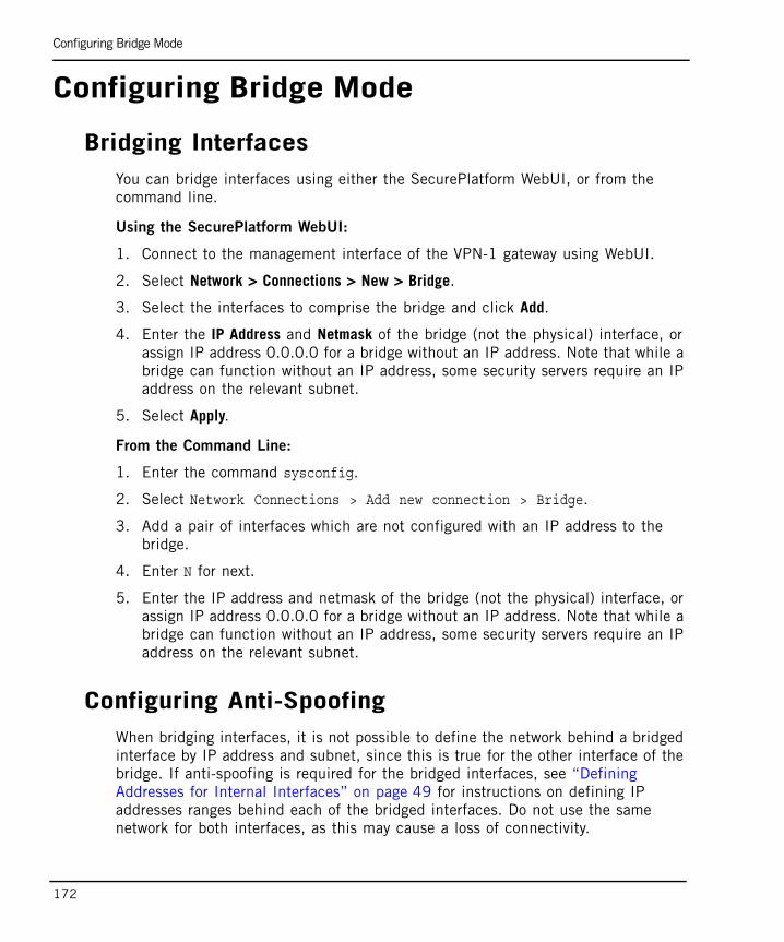
Configuring Bridge Mode
172
Configuring Bridge Mode
Bridging InterfacesYou can bridge interfaces using either the SecurePlatform WebUI, or from the command line.
Using the SecurePlatform WebUI:
1. Connect to the management interface of the VPN-1 gateway using WebUI.
2. Select Network > Connections > New > Bridge.
3. Select the interfaces to comprise the bridge and click Add.
4. Enter the IP Address and Netmask of the bridge (not the physical) interface, or assign IP address 0.0.0.0 for a bridge without an IP address. Note that while a bridge can function without an IP address, some security servers require an IP address on the relevant subnet.
5. Select Apply.
From the Command Line:
1. Enter the command sysconfig.
2. Select Network Connections > Add new connection > Bridge.
3. Add a pair of interfaces which are not configured with an IP address to the bridge.
4. Enter N for next.
5. Enter the IP address and netmask of the bridge (not the physical) interface, or assign IP address 0.0.0.0 for a bridge without an IP address. Note that while a bridge can function without an IP address, some security servers require an IP address on the relevant subnet.
Configuring Anti-SpoofingWhen bridging interfaces, it is not possible to define the network behind a bridged interface by IP address and subnet, since this is true for the other interface of the bridge. If anti-spoofing is required for the bridged interfaces, see “Defining Addresses for Internal Interfaces” on page 49 for instructions on defining IP addresses ranges behind each of the bridged interfaces. Do not use the same network for both interfaces, as this may cause a loss of connectivity.
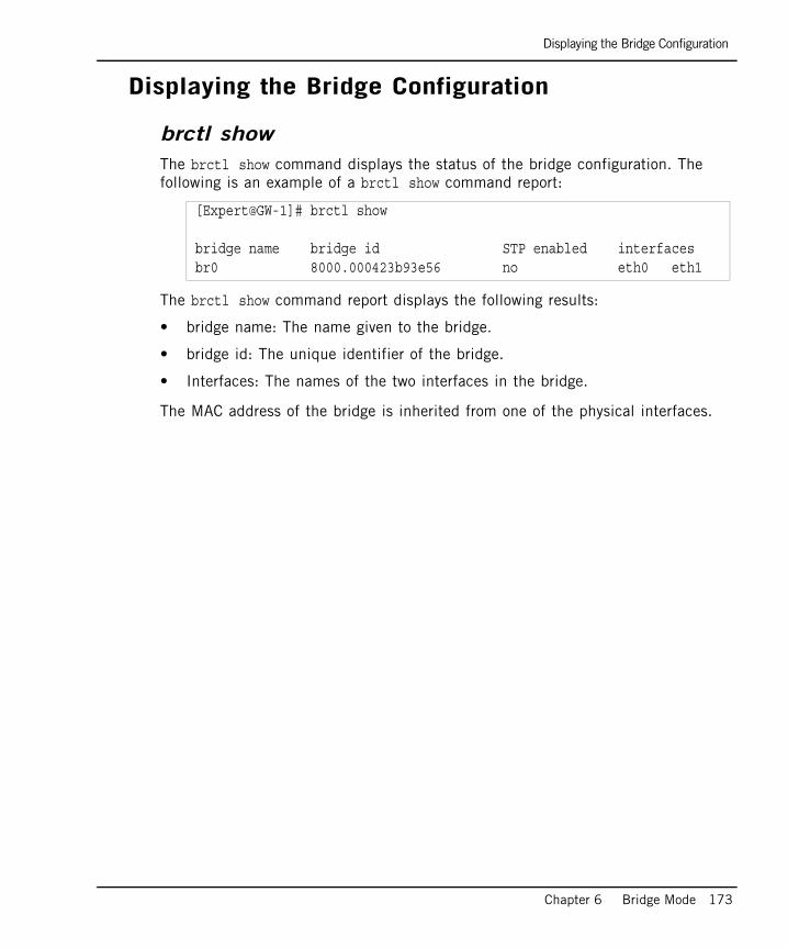
Displaying the Bridge Configuration
Chapter 6 Bridge Mode 173
Displaying the Bridge Configuration
brctl showThe brctl show command displays the status of the bridge configuration. The following is an example of a brctl show command report:
The brctl show command report displays the following results:
• bridge name: The name given to the bridge.
• bridge id: The unique identifier of the bridge.
• Interfaces: The names of the two interfaces in the bridge.
The MAC address of the bridge is inherited from one of the physical interfaces.
[Expert@GW-1]# brctl show
bridge name bridge id STP enabled interfacesbr0 8000.000423b93e56 no eth0 eth1

Displaying the Bridge Configuration
174
SmartDefenseThis section gives a conceptual overview of SmartDefense, which enables customers to configure, enforce and update network and application attack defenses. The DShield StormCenter is also described in detail. For information about specific protections, see the SmartDefense HTML pages and the online help.


177
Chapter 7SmartDefense
In This Chapter
The Need for SmartDefense page 178
SmartDefense Solution page 180
Network Security page 188
Application Intelligence page 195
Web Intelligence page 198
Configuring SmartDefense page 210
SmartDefense Services page 211
Configuring SmartDefense Profiles page 214
SmartDefense StormCenter Module page 216
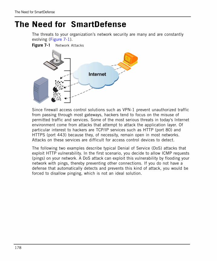
The Need for SmartDefense
178
The Need for SmartDefenseThe threats to your organization’s network security are many and are constantly evolving (Figure 7-1). Figure 7-1 Network Attacks
Since firewall access control solutions such as VPN-1 prevent unauthorized traffic from passing through most gateways, hackers tend to focus on the misuse of permitted traffic and services. Some of the most serious threats in today's Internet environment come from attacks that attempt to attack the application layer. Of particular interest to hackers are TCP/IP services such as HTTP (port 80) and HTTPS (port 443) because they, of necessity, remain open in most networks. Attacks on these services are difficult for access control devices to detect.
The following two examples describe typical Denial of Service (DoS) attacks that exploit HTTP vulnerability. In the first scenario, you decide to allow ICMP requests (pings) on your network. A DoS attack can exploit this vulnerability by flooding your network with pings, thereby preventing other connections. If you do not have a defense that automatically detects and prevents this kind of attack, you would be forced to disallow pinging, which is not an ideal solution.
The Need for SmartDefense
Chapter 7 SmartDefense 179
In the second scenario, SYN attacks disrupt TCP/IP traffic by sending SYN packets and then not acknowledging the TCP/IP server response packet. This causes the server to keep signaling until it eventually times out. This is a problem because disabling TCP/IP is not an option. There are other solutions available, such as content security applications (virus scanners), but these applications are inadequate because they are limited to specific services and they are unable to detect patterns of hacker activity.
Securing your network with up-to-date detection methods that prevent attacks is critical to safeguarding your organization’s data and communications. SmartDefense is the only solution that addresses such threats in a reliable and effective manner. The following sections describe the SmartDefense solution to the ever evolving nature of attacks on the network perimeter.
SmartDefense Solution
180
SmartDefense Solution In This Section
Introducing SmartDefenseSmartDefense is an integral part of VPN-1, providing a unified security framework that identifies and prevents attacks. SmartDefense defends your network even if protection is not explicitly defined in the Rule Base. It unobtrusively analyzes activity across your network, tracking potentially threatening events and sending notifications. It protects organizations from all known, and most unknown, network attacks using intelligent security technology. A single click allows you to update SmartDefense with the latest defenses from the SmartDefense website.
SmartDefense protection is fully customizable allowing you to:
• Select the attacks that you want to protect your network against and receive detailed information on those attacks.
• Configure parameters for each attack, including logging options.
• Receive real time information on attacks and update SmartDefense with new the latest features and capabilities.
The SmartDefense page in the SmartDashboard window has a tree-structured navigation pane that classifies protections into several categories: “Network Security”, “Application Intelligence” and “Web Intelligence”.
Introducing SmartDefense page 180
Defending Against the Next Generation of Threats page 181
Network and Transport Layers page 182
Web Attack Protection page 182
How SmartDefense Works page 183
Categorizing SmartDefense Capabilities page 184
SmartDefense Profiles page 186
Monitor-Only Mode page 187
Note - When updating SmartDefense, new categories, as well as attack defenses, may be added to the tree structure.
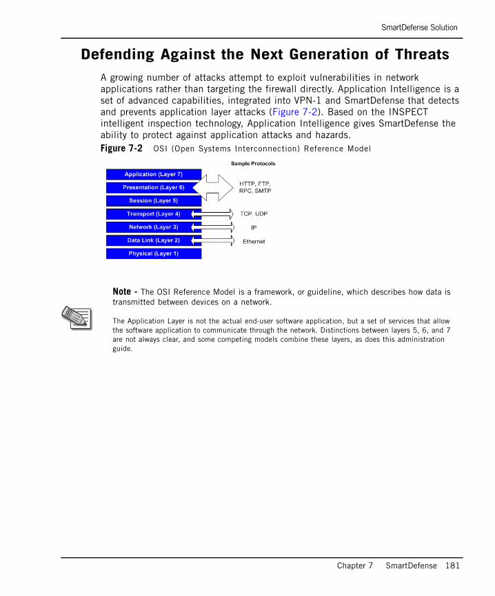
SmartDefense Solution
Chapter 7 SmartDefense 181
Defending Against the Next Generation of ThreatsA growing number of attacks attempt to exploit vulnerabilities in network applications rather than targeting the firewall directly. Application Intelligence is a set of advanced capabilities, integrated into VPN-1 and SmartDefense that detects and prevents application layer attacks (Figure 7-2). Based on the INSPECT intelligent inspection technology, Application Intelligence gives SmartDefense the ability to protect against application attacks and hazards.Figure 7-2 OSI (Open Systems Interconnection) Reference Model
Note - The OSI Reference Model is a framework, or guideline, which describes how data is transmitted between devices on a network.
The Application Layer is not the actual end-user software application, but a set of services that allow the software application to communicate through the network. Distinctions between layers 5, 6, and 7 are not always clear, and some competing models combine these layers, as does this administration guide.

SmartDefense Solution
182
Network and Transport LayersApplication Intelligence works primarily with application layer defenses. However, in practice, many attacks aimed at network applications actually target the network and the transport layers.
Hackers target these lower layers as a means to access the application layer, and ultimately the application and its data. In addition, by targeting lower layers, attacks can interrupt or deny service to legitimate users and applications (for example, DoS attacks). For these reasons, SmartDefense addresses not only the application layer, but also the network and transport layers.
Preventing the manipulation of network-layer protocols (for example, IP and ICMP) is a crucial requirement for multilevel security gateways. The most common vehicle for attacks against the network layer is the Internet Protocol (IP), whose set of services resides within this layer.
As with the network layer, the transport layer and its common protocols (for example, TCP and UDP) provide popular access points for attacks on applications and their data.
Web Attack ProtectionWeb servers and web applications have evolved from their origins as serving simple static content. Today, Web servers and applications can create dynamic pages, invoke other applications, and communicate with databases to produce useful content for users. With most Web server platforms bundling applications with the server, even the simplest web sites interact with web applications.Figure 7-3 Multiple Security Vulnerabilities in the N-Tier Web Architecture
With almost all organizations allowing web traffic (TCP port 80) through their perimeter firewall, hackers are increasingly focusing their attacks on Web servers and applications. Many attacks today exploit security weaknesses in the different layers of web architecture. These attacks include defacing the primary web
SmartDefense Solution
Chapter 7 SmartDefense 183
interface, getting an embedded web application on a server to do unintended functions, installing malicious applications and tricking the backend database to send information back to the user.
Like network security, web security is only as strong as the weakest link. To build secure web applications, web developers must build security into every aspect of the application. Unfortunately, many enterprise web applications are not designed with holistic security in mind. Even worse, an organization may incorporate web security into only some of the Web servers that are accessible to the outside world.
Web Intelligence pages enables customers to configure, enforce and update attack protections for Web servers and applications. Web Intelligence protections are designed specifically for web-based attacks, and complement the network and application level protections offered by SmartDefense. In addition, Web Intelligence Advisories, published online by Check Point, provide information and add new attack defenses.
Web Intelligence not only protects against a range of known attacks, but also incorporates intelligent security technologies that protect against entire categories of emerging or unknown attacks. Unlike web firewalls and traditional intrusion protection systems, Web Intelligence provides proactive attack protections. This ensures that communication between clients and Web servers complies with published standards and security best practices, restricts hackers from executing irrelevant system commands, and inspects traffic passing to Web servers to ensure that it does not contain malicious code. Web Intelligence allows organizations to permit access to their Web servers and applications without sacrificing either security or performance.
How SmartDefense WorksSmartDefense is integrated into VPN-1. As all inbound traffic is routed through the firewall, as this is the logical place for active defenses to reside. Some SmartDefense capabilities are enforced at the network boundary, while others, such as Abnormal Behavior Analysis, are managed from the SmartCenter server. The SmartDefense protections are distributed as part of the security policy to each gateway from the SmartCenter server. SmartDefense blocks attacks at the network boundary using Check Point's Stateful Inspection technology.
SmartDefense Solution
184
Online UpdatesCustomers who purchase the SmartDefense subscription service can automatically update SmartDefense with a single click. Updates are released frequently, and can be obtained from the Check Point SmartDefense site:
http://www.checkpoint.com/techsupport/documentation/smartdefense/index.html
Customers with a valid subscription license also receive special SmartDefense Advisories that provide updated SmartDefense attack protections, as well as information, tools and best practice methods to mitigate different attacks.
Categorizing SmartDefense CapabilitiesSmartDefense protects your organization against attacks and other illegitimate or unwanted network activity using the following categories of SmartDefense capabilities:
• “Defense Against Attacks” on page 184.
• “Information Disclosure Prevention” on page 185.
• “Abnormal Behavior Analysis” on page 185.
Some SmartDefense features provide more than one category of protection. For example, the Initial Sequence Number Defender (ISN Defender) defends against both the specific attack and Implicit Defense.
Defense Against Attacks SmartDefense protects organizations from known and unknown network attacks. Attacks are stopped at the gateway and are prevented from affecting the target server. SmartDefense is easy to configure, and defends against attacks while freeing the administrator from the need to understand the technical details of the attack.
SmartDefense protects your network against the following types of attacks:
• Denial of Service Attacks
• TCP/IP Attacks
Tip - It is recommended to keep your gateway version up-to-date, as the newest defenses are incorporated into the latest version of Check Point software.
SmartDefense Solution
Chapter 7 SmartDefense 185
• Web and Application Vulnerabilities
• Network Probing
• HTTP Worms
For example, consider a TCP/IP attack called ISN Guessing. TCP/IP connections are initiated by way of a three-way handshake: the client sends a SYN packet, the server replies with a SYN/ACK and the client sends an ACK packet to acknowledge the connection. With each SYN/ACK, the server also generates an initial sequence number (ISN or SN) that identifies the connection. The SNs are generated using a key, and in some operating systems you can guess the next SN based on the previous SN. If an external client successfully guesses the next valid SN, it can then open a connection to the server by sending a SYN/ACK packet with a valid SN. This connection could be from a nonexistent IP address and may carry damaging data.
SmartDefense fends off this type of attack by replacing the server as the SN generator and using an encrypted key to generate SNs less susceptible to attack.
Information Disclosure PreventionImplicit Defense prevents information on network entities from reaching the Internet, where the information could be misused.
Using the SN vulnerability example in “Defense Against Attacks” on page 184, when an internal server establishes a TCP connection, it sends successive SNs. Under certain conditions, these SNs can be used to identify the source’s operating system. SmartDefense uses fingerprint spoofing to replace one fingerprint with another, thereby making it impossible for external clients to discover the operating system used by the internal servers.
Abnormal Behavior AnalysisSmartDefense analyzes patterns of abnormal network behavior. It detects these patterns by analyzing logs sent to the SmartCenter server by the VPN-1 gateways. If a suspicious pattern is detected, the administrator can track the activity using a log or an alert (depending on the configuration setting).
Using the Port Scan detection feature, whenever SmartDefense detects port scanning, it logs the activity and issues an alert.

SmartDefense Solution
186
SmartDefense ProfilesSince there are many different kinds of threats to your network’s security, different gateways may require different configurations in order to guard against the increasing number and variety of threats. SmartDefense Profiles enable the administrator to customize the SmartDefense protection according to the needs of each gateway in the community. A SmartDefense Profile may be installed on more than one gateway.
The following features are configured universally for all gateways:
• Spoofed Reset Protection: The services exclusion list, which is applied globally (not per profile).
• Successive Events: The settings relevant for log servers and not for each gateway.
• DShield Storm Center (Report to DShield): The settings that are not part of the firewall and therefore cannot have different settings.
• Definitions of patterns (worm catcher patterns, P2P/IM patterns): The definition is global and each pattern can be activated/deactivated in each profile.
If you do not specify a profile to a gateway, the default profile is assigned.
Up to 20 profiles may be created. SmartDefense Profiles are available for all NGX R60 gateways and above.
For Connectra, SmartDefense Profiles are available for all NGX R62CM gateways and above. Earlier versions of Connectra gateway do not receive a SmartDefense profile from SmartCenter.
To configure SmartDefense Profiles refer to “Configuring SmartDefense Profiles” on page 214.
Note - Every profile created takes 2 MB of RAM from the user console machine on both Windows and Motif.

SmartDefense Solution
Chapter 7 SmartDefense 187
Monitor-Only ModeMany protections have a monitor-only option, which detects and tracks unauthorized traffic without blocking it (refer to Figure 7-4). Intrusions are logged in SmartView Tracker. Figure 7-4 Protection Scope and Action Settings
The monitor-only option is helpful when deploying a protection for the first time, in order to evaluate the effectiveness of the protection without interrupting connectivity. Monitor-only mode also enables audit-only deployment.
Special Monitor-Only ModeWhen all active protections are in monitor-only mode, connections that contain non-HTTP compliant data are not rejected. In this special mode, SmartDefense does not affect traffic at all. In contrast, when only some of the active protections are in monitor mode-only, non-HTTP compliant traffic is rejected.
This special operating mode is especially helpful when deploying SmartDefense for the first time, to evaluate its effectiveness without interrupting connectivity, or when troubleshooting a problem that is related to blocking traffic.
Monitor-Only Per Web ServerAll protections on a particular Web server can be set to monitor-only. This makes it possible to put a new Web server in place and investigate which protections it needs, while ensuring that connectivity is maintained.
To configure a monitor-only per Web server, use the Check Point Database Tool (GUIdbedit, located in the SmartConsole installation directory). Using GuiDBedit, search for the Web server name, and then set the web_server_monitor_only field to TRUE.
Network Security
188
Network SecurityFrom the Network Security pages, you can configure various SmartDefense protections against attacks on the network and transport levels. Such attacks, which occur on the IP, TCP, UDP or ICMP network protocols, range from the identification of your organization’s operating systems to denial of service attacks on hosts and servers on the network. Each SmartDefense protection is accompanied by a corresponding description of the attack.
Japanese Language Support for SmartDefense Protections
When SmartConsole detects the underlying operating system to be Japanese enabled, it displays the description pages for each SmartDefense protection in Japanese.
This behavior can be controlled via a new property in the database: gui_client_lang as shown in Figure 7-5:
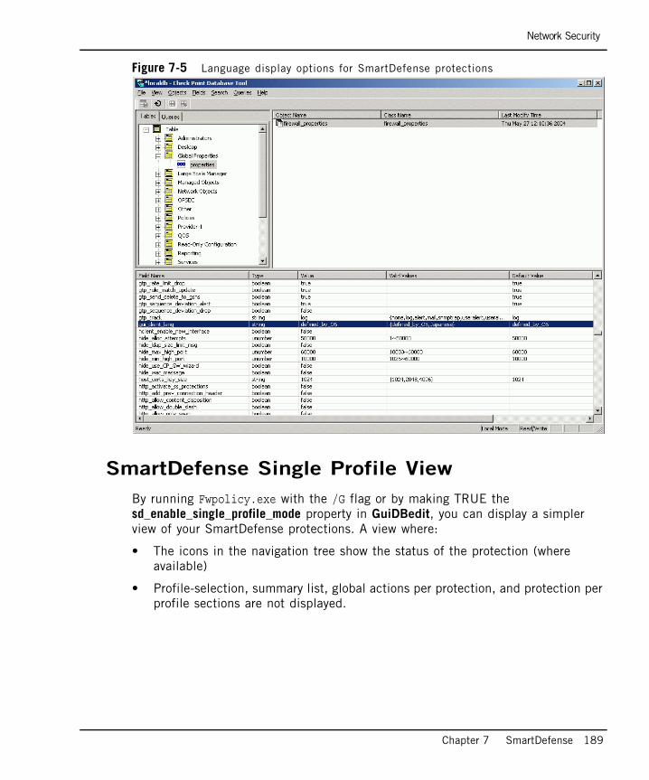
Network Security
Chapter 7 SmartDefense 189
Figure 7-5 Language display options for SmartDefense protections
SmartDefense Single Profile View
By running Fwpolicy.exe with the /G flag or by making TRUE the sd_enable_single_profile_mode property in GuiDBedit, you can display a simpler view of your SmartDefense protections. A view where:
• The icons in the navigation tree show the status of the protection (where available)
• Profile-selection, summary list, global actions per protection, and protection per profile sections are not displayed.
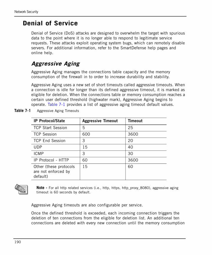
Network Security
190
Denial of ServiceDenial of Service (DoS) attacks are designed to overwhelm the target with spurious data to the point where it is no longer able to respond to legitimate service requests. These attacks exploit operating system bugs, which can remotely disable servers. For additional information, refer to the SmartDefense help pages and online help.
Aggressive AgingAggressive Aging manages the connections table capacity and the memory consumption of the firewall in to order to increase durability and stability.
Aggressive Aging uses a new set of short timeouts called aggressive timeouts. When a connection is idle for longer than its defined aggressive timeout, it is marked as eligible for deletion. When the connections table or memory consumption reaches a certain user defined threshold (highwater mark), Aggressive Aging begins to operate. Table 7-1 provides a list of aggressive aging timeout default values.
Table 7-1 Aggressive Aging Timeouts
Aggressive Aging timeouts are also configurable per service.
Once the defined threshold is exceeded, each incoming connection triggers the deletion of ten connections from the eligible for deletion list. An additional ten connections are deleted with every new connection until the memory consumption
IP Protocol/State Aggressive Timeout Timeout
TCP Start Session 5 25
TCP Session 600 3600
TCP End Session 3 20
UDP 15 40
ICMP 3 30
IP Protocol - HTTP 60 3600
Other (these protocols are not enforced by default)
15 60
Note - For all http related services (i.e., http, https, http_proxy_8080), aggressive aging timeout is 60 seconds by default.

Network Security
Chapter 7 SmartDefense 191
or the connections capacity falls below a certain low watermark. If there are no "eligible for deletion" connections, no connections are deleted at that time but the list is checked after each subsequent connection that exceeds the highwater mark.
Timeout settings are a key factor in memory consumption configuration. When timeout values are low, connections are deleted faster from the table, enabling the firewall to handle more connections concurrently. When memory consumption exceeds its threshold, it is best to work with shorter timeouts that can maintain the connectivity of the vast majority of the traffic.
The major benefit of Aggressive aging is that is starts to operate when the machine still has available memory and the connections table is not entirely full. This way, it reduces the chance to encounter connectivity problems that might have occurred under low resources conditions.
Aggressive Aging allows the gateway machine to handle large amounts of unexpected traffic, especially during a DoS attack.
If a SecureXL device does not support Aggressive Aging, then the feature is disabled. When this happens, the action is logged and a console message is generated. All SecureXL NGX R65 devices support Aggressive Aging.
IP and ICMPIP and ICMP provides a comprehensive sequence of layer three tests for the IP and ICMP protocols. For example, the Fragmentation Timeout Logs feature generates logs when it detects packets that have been fragmented for a firewall bypassing or a DoS attack. For additional information, refer to the SmartDefense help pages and online help.
TCPVPN-1 can identify the basic IP based protocols and analyze a packet in order to verify that it only contains permitted options. The following tests are conducted to verify that TCP packets are legitimate:
• Protocol type verification
• Protocol header analysis
• Protocol flags analysis and verification
SYN Attack Protection prevents attacks in which TCP connection initiation packets are sent to the server in an attempt to cause denial of service.
Network Security
192
The Sequence Verifier is a mechanism that matches the current TCP packet sequence number to the TCP connection state. Packets that match the connection in terms of the TCP session but have incorrect sequence numbers are either dropped or stripped of data. For additional information, refer to the SmartDefense help pages and online help.
Fingerprint ScramblingIt is sometimes possible to identify a machine’s operating system or to impersonate an existing connection with a fingerprint that identifies the operating system or the connection. The SmartDefense Fingerprint Scrambling feature prevents this by distorting the fingerprint in order to make identification impossible. For additional information, refer to the SmartDefense help pages and online help.
Successive EventsThe Successive Events feature detects malicious or suspicious events and notifies the security administrator. Successive Events detection runs on the SmartCenter server and analyzes logs from VPN-1 gateways by matching log entries to attack profiles. The security administrator can modify attack detection parameters, enable/disable detection for specific attacks or disable the Successive Events feature.
Logs that do not reach the SmartCenter server (for example, local logs and logs sent to the Log server) are not analyzed. For additional information, refer to the SmartDefense help pages and online help
DShield Storm CenterStorm Centers gather logging information on attacks. This information is voluntarily provided by organizations worldwide for the benefit of all. Storm Centers collate and present reports on real-time threats to network security.
The SmartDefense Storm Center Module updates your organization with the latest attack information from other Storm Centers and allows you to contribute your attack logs to their databases.
One of the leading Storm Centers is SANS DShield.org. SmartDefense integrates with the SANS DShield.org Storm Center in the following ways:

Network Security
Chapter 7 SmartDefense 193
• The DShield.org Storm Center produces a Block List report, which is a list of address ranges that are recommended for blocking. This list is frequently updated. The SmartDefense Storm Center Module retrieves and immediately adds this list to the security policy.
• Sending logs to the Storm Center to help other organizations combat threats that were directed at your network. You can decide which logs to send by selecting the rules for which you want to send logs.
For additional information on SmartDefense DShield Storm Center integration, refer to “SmartDefense StormCenter Module” on page 216.
Port ScanPort Scanning is an information collection method for open TCP and UDP ports in a network. Although the collection of information does not in itself constitute an attack, this information can be used later to target and attack vulnerable computers.
In order to offer a service to another computer, a host must open a port for that service. Ports often remain open in default installations, unbeknownst to the administrator, leaving the host vulnerable to attack. For example, if the FTP service is left open by default, an attacker can try to guess the default username and password in order to gain access to the machine. Port scanning can be performed either by a hacker using a scanning utility, or by a worm attempting to spread to other computers. Port scanning is most commonly performed by trying to access a port and waiting for a response, whereby the response indicates whether or not the port is open.
The SmartDefense Port Scanning feature does not block the scanning, but detects ports scans with one of three levels of detection sensitivity. When a port scan is detected, a log or an alert is issued.
Network Security
194
You can block clients that SmartDefense detects as sources of port scanning by configuring automatic SAM (Suspicious Activity Monitoring) alert rules on the SmartCenter server to block the offending IP addresses. For additional information on the sam_alert command, refer to the Command Line Interface (CLI) Administration Guide.
For additional information, refer to the SmartDefense help pages and online help.
Dynamic PortsA number of services (such as FTP under heavy load and SIP protocols) can set up connections by opening ports dynamically. These ports can turn out to be the same as those used by one of the predefined services in SmartDashboard. From the Dynamic Ports page, you can define whether to drop a connection with a dynamically opened port that is the same as a predefined service port. You can also decide whether to drop dynamic port connections that use low port numbers (below 1024). For additional information, refer to the SmartDefense help pages and online help.
Warning - An automatic sam_alert rule may expose legitimate hosts to a remote DoS attack. An attacker could spoof a port scan from a legitimate IP, which would then be blocked by the automatic SAM rule.

Application Intelligence
Chapter 7 SmartDefense 195
Application IntelligenceApplication Intelligence pages allow you to configure various protections at the application layer.
MailThe SMTP security server enables strict enforcement of the SMTP protocol. It protects against malicious mail messages, provides SMTP protocol centered security, prevents attempts to bypass the Rule Base using mail relays, and prevents Denial of Service and spam mail attacks. Normally, the security server is activated by specifying resources or authentication rules in the Security Rule Base.
You can define which types of enforcement are applied to SMTP connections passing through the security server. The Configuration applies to all connections option forwards all SMTP connections to the SMTP security server and enforces the defined settings on all connections without having to define a resource in the Rule Base. The Configurations apply only to connections related to Rule Base defined objects option only applies these configurations to SMTP connections for which a resource is defined in the Rule Base.
For additional information, refer to the SmartDefense help pages and online help.
FTPYou can configure various protections related to the FTP protocol. For example, preventing FTP port overflow checks and foils any attempt to use an FTP server as an agent for a malicious operation.
For additional information, refer to “FTP Security” on page 333 and the SmartDefense help pages and online help.
Microsoft NetworksYou can configure various protections at the application layer, using SmartDefense's Application Intelligence capabilities. For additional information, refer to “Microsoft Networking Services (CIFS) Security” on page 329 and the SmartDefense help pages and online help.
Application Intelligence
196
Peer-to-PeerSmartDefense can block peer-to-peer traffic by identifying the proprietary protocols and preventing the initial connection to the peer to peer networks. This not only prevents, but also search operations. SmartDefense can identify the protocol even if the peer to peer application switches port numbers. The detection does not, for example, rely on identifying HTTP header signatures. For additional information, refer to the SmartDefense HTML pages and online help.
Instant MessengersYou can block Instant Messaging applications that use VoIP protocols. Instant Messaging applications have many capabilities, including voice calls, message transfer and file sharing. For additional information, refer to the SmartDefense HTML pages and online help.
DNSThe DNS protocol identifies servers by their IP addresses and aliases. DNS protocol messages can be transported over TCP or UDP. This option verifies that all the connections on the DNS port over UDP are DNS related. In addition, certain restrictions are imposed on the type of data allowed in queries and answers. For additional information, refer to the SmartDefense HTML pages and online help.
VoIPVoice and video traffic must to be protected as it enters and leaves a network. Potential threats to voice and video traffic are:
• Call redirections whereby calls intended for one recipient are redirected to another.
• Stealing calls, where the caller pretends to be someone else.
• System hacking using ports opened for VoIP connections.
VoIP calls involve a series of complex protocols, each of which can carry potentially threatening information through many ports.
SmartDefense ensures that caller and recipient addresses are valid and that the caller and recipient can make and receive VoIP calls. SmartDefense also examines the contents of the packets passing through every allowed port to ensure that they

Application Intelligence
Chapter 7 SmartDefense 197
contain the proper information. Full stateful inspection on H.323, SIP, MGCP and SCCP commands ensures that all VoIP packets are structurally valid and that they arrive in a valid sequence.
For additional information, refer to “Securing Voice Over IP (VoIP)” on page 247.
SNMPSmartDefense enables you to protect against SNMP vulnerabilities by providing the option of enforcing SNMPv3 (the latest SNMP version) while rejecting previous versions. In addition, SmartDefense can allow all SNMP versions while dropping requests with SNMPv1 and SNMPv2 default community strings. Monitor-only mode enables you to track unauthorized traffic without blocking it. For additional information, refer to the SmartDefense HTML pages and online help.

Web Intelligence
198
Web IntelligenceIn This Section
Web Intelligence focuses on protecting Web servers against attacks. As such, Web server objects are defined, and protections are applied either to all Web servers or to selected Web servers. Any gateway or host object can be defined as a Web server.
Web Intelligence ProtectionsWeb Intelligence protections are organized into a number of protection classes
Malicious CodeThese protections prevent attacks that attempt to run malicious code on Web servers .
Application LayerThis class of protection prevents hackers from introducing text, tags, commands, or other characters that a web application will interpret as special instructions.
Introducing such objects into forms or URLs can allow a hacker to steal private data, redirect a communication session to a malicious web site, steal information from a database, gain unauthorized access, or execute restricted commands.
Web Intelligence Protections page 198
Web Intelligence Technologies page 199
Web Intelligence and ClusterXL Gateway Clusters page 199
Web Content Protections page 200
Customizable Error Page page 200
Connectivity Versus Security Considerations page 201
Web Security Performance Considerations page 203
Backward Compatibility Options for HTTP Protocol Inspection page 205
Web Intelligence License Enforcement page 205
Understanding HTTP Sessions, Connections and URLs page 207
Web Intelligence
Chapter 7 SmartDefense 199
Information DisclosureThese protections prevent an attacker from gathering information about a web site. The goal of information disclosure is to obtain information from the Web server that can be used to tailor an attack.
HTTP Protocol InspectionHTTP Protocol Inspection provides strict enforcement of the HTTP protocol, ensuring that sessions comply with RFC standards and common security practices.
Web Intelligence TechnologiesWeb Intelligence is based on Check Point's Stateful Inspection, Application Intelligence, and Malicious Code Protector technologies, so that it is possible to block not only specific attacks, but also entire categories of attacks, while allowing legitimate traffic to pass.
• Malicious Code Protector is a Check Point patent-pending technology that blocks hackers from sending malicious code to target Web servers and applications. It can detect malicious executable code within web communications by identifying not only the existence of executable code in a data stream but its potential for malicious behavior. Malicious Code Protector is a kernel-based protection delivering almost wire-speed performance.
• Application Intelligence is a set of technologies that detect and prevent application-level attacks by integrating a deeper understanding of application behavior into network security defenses.
• Stateful Inspection analyzes the information flow into and out of a network so that real-time security decisions are based on communication session information as well as on application information. It accomplishes this by tracking the state and context of all communications traversing the firewall gateway, even when the connection involves complex protocols.
Web Intelligence and ClusterXL Gateway ClustersWeb Intelligence features on a ClusterXL gateway cluster do not survive failover. This means that if ClusterXL is providing Web Intelligence protections and a cluster member fails, HTTP connections passing through the failed member are lost.
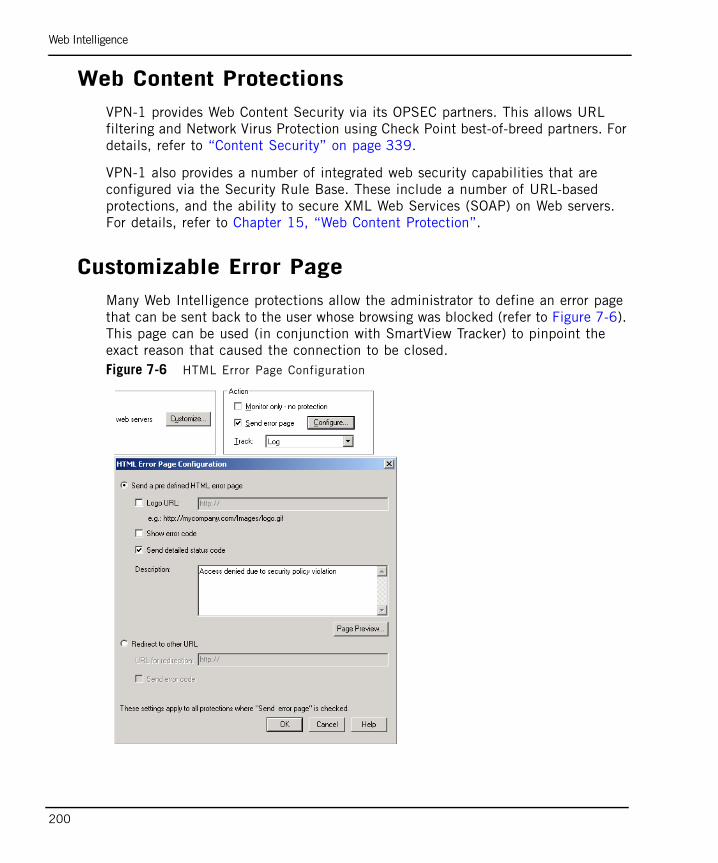
Web Intelligence
200
Web Content ProtectionsVPN-1 provides Web Content Security via its OPSEC partners. This allows URL filtering and Network Virus Protection using Check Point best-of-breed partners. For details, refer to “Content Security” on page 339.
VPN-1 also provides a number of integrated web security capabilities that are configured via the Security Rule Base. These include a number of URL-based protections, and the ability to secure XML Web Services (SOAP) on Web servers. For details, refer to Chapter 15, “Web Content Protection”.
Customizable Error PageMany Web Intelligence protections allow the administrator to define an error page that can be sent back to the user whose browsing was blocked (refer to Figure 7-6). This page can be used (in conjunction with SmartView Tracker) to pinpoint the exact reason that caused the connection to be closed.Figure 7-6 HTML Error Page Configuration
Web Intelligence
Chapter 7 SmartDefense 201
This makes it possible to quickly nail down and eliminate the attack, before it can spread. The security administrator can fix the problem even before users know about it, or if the users notice the problem first, they can call the Help Desk about it. Alternatively, users can be given information in the web page about how to fix the problem themselves, which is of great benefit to overworked support staff.
The administrator can customize the page to include text and a logo. To help pinpoint the reason that caused the connection to be closed, the page shows two IDs: a Reject ID and an Error Description ID.
Reject IDThe Reject ID that appears on the error page is intended to deliver information to the administrator without exposing it to a potential attacker.
The Reject ID is unique for each rejected connection. The Reject ID also appears in the SmartView Tracker and allows the administrator to correlate between an error and a log record of a specific connection. The log record contains attack information, such as “Cross site scripting detected”.
Error Description IDThe Error Description ID is a standard ID that is used to identify the attack. It appears in the SmartView Tracker log and corresponds to a SecureKnowledge solution about the attack. For example, the following could appear in the Information column of the SmartView Tracker log: “WSE0030002 cross site scripting detected in request”. The WSE0030002 is the Error description ID, and a SecureKnowledge search for that ID will locate information about the attack.
The administrator can decide whether or not to display the Error Description ID on the error page. Due to the potential for misuse by an attacker, it is recommended that you do not display this information .
Connectivity Versus Security ConsiderationsWeb Intelligence can be tuned for greater Web server security at the expense of connectivity, or vice versa.
Note - Activating the Error Page decreases performance for Web traffic to which this fea-ture is applied.

Web Intelligence
202
Monitor-Only ModeAll Web Intelligence protections have a monitor-only mode which makes it possible to evaluate how the protection will affect connectivity, by examining logs to spot traffic that Web Intelligence has detected as being dangerous. All this, while allowing uninterrupted traffic flow.
Protection for Specific ServersAll Web Intelligence defenses can be activated for specific Web servers. If the protection is problematic on a particular Web server, it can be turned off for that specific Web server.
Variable Security LevelsSome of the advanced defenses (Cross Site Scripting, Command Injection, SQL injection and Malicious Code Protector) have variable security level settings. If a connectivity problem arises on a specific Web server, the security level can be lowered for that Web server.
Connectivity Implications of Specific ProtectionsHTTP protocol inspection settings that are too severe can affect connectivity to and from valid Web servers.
• HTTP Format sizes protection restricts URL lengths, header lengths or the number of headers. This is good practice because these elements can be used to perform a Denial of Service attack on a Web server. At the same time, these restrictions can potentially block valid sites. Applying the protection for specific Web servers can solve the connectivity problems.
• ASCII only Request Header protection can block connectivity to web pages that have non-ASCII characters in URLs. Applying the protection for specific Web servers can solve the connectivity problems.
HTTP methods - Some standard and non-standard HTTP methods are unsafe, because they can be used to exploit vulnerabilities on a Web server. Microsoft WebDAV methods (used for Outlook Express access to Hotmail), for example, have certain security issues, but blocking them can prevent the use of important applications. Applying the protection for specific Web servers can solve the connectivity problems.
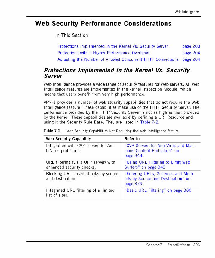
Web Intelligence
Chapter 7 SmartDefense 203
Web Security Performance Considerations
In This Section
Protections Implemented in the Kernel Vs. Security ServerWeb Intelligence provides a wide range of security features for Web servers. All Web Intelligence features are implemented in the kernel Inspection Module, which means that users benefit from very high performance.
VPN-1 provides a number of web security capabilities that do not require the Web Intelligence feature. These capabilities make use of the HTTP Security Server. The performance provided by the HTTP Security Server is not as high as that provided by the kernel. These capabilities are available by defining a URI Resource and using it the Security Rule Base. They are listed in Table 7-2.
Protections Implemented in the Kernel Vs. Security Server page 203
Protections with a Higher Performance Overhead page 204
Adjusting the Number of Allowed Concurrent HTTP Connections page 204
Table 7-2 Web Security Capabilities Not Requiring the Web Intelligence feature
Web Security Capability Refer to
Integration with CVP servers for An-ti-Virus protection.
“CVP Servers for Anti-Virus and Mali-cious Content Protection” on page 344.
URL filtering (via a UFP server) with enhanced security checks.
“Using URL Filtering to Limit Web Surfers” on page 348
Blocking URL-based attacks by source and destination
“Filtering URLs, Schemes and Meth-ods by Source and Destination” on page 379.
Integrated URL filtering of a limited list of sites.
“Basic URL Filtering” on page 380

Web Intelligence
204
Protections with a Higher Performance OverheadWeb Intelligence default protections are optimized to blend high security and performance.
Activating the following features decreases performance for the web traffic to which these features are applied:
• Custom HTML error pages.
• Header Spoofing, where headers are rewritten.
• ASCII Only Response Headers, where the HTTP response is inspected.
Adjusting the Number of Allowed Concurrent HTTP ConnectionsIt is possible to adjust the resources available for HTTP connections on the VPN-1 gateway. If the traffic volume is greater than 1000 concurrent connections, you can increase the allowed maximum number of concurrent HTTP connections. Conversely, if there is a problem installing the security policy due to a lack of memory, you can decrease the allowed maximum number of concurrent connections.
From the SmartDashboard main menu, select Policy> Global Properties, and then SmartDashboard Customization > Configure. In the Advanced Configuration window, select FireWall-1 > Web Security > Tuning. Adjust the value of the parameter http_max_concurrent_connections. The default value is 1000.
HTML weeding: Stripping script tags, Applet tags, ActiveX, FTP links and port Strings.
“Java and ActiveX Security” on page 381.
HTTP Response scanning: Blocking Java Code.
“Java and ActiveX Security” on page 381
Securing XML Web Services (SOAP). “Securing XML Web Services (SOAP)” on page 382.
Table 7-2 Web Security Capabilities Not Requiring the Web Intelligence feature
Web Security Capability Refer to
Web Intelligence
Chapter 7 SmartDefense 205
Backward Compatibility Options for HTTP Protocol Inspection
Web Intelligence performs high performance kernel-level inspection of all connections passing through version NG with Application Intelligence (R55W) gateways or higher.
On earlier version gateways, you have a choice. In Web Intelligence, under HTTP Protocol Inspection, it is possible to choose whether to perform HTTP protocol inspection using the kernel for optimized performance, or using the HTTP Security Server for strict protocol enforcement. The three options are:
• Configurations apply to all connections: Perform optimized protocol enforcement
The following HTTP protocol inspection options are enforced by the kernel on all connections (if active): HTTP Format sizes, ASCII Only Request, Header Rejection, and General HTTP Worm Catcher. Note that in this option, the ASCII Only Response Headers protection is not performed. If a connection matches a rule in the Rule Base that activates the Security server, the Security server performs these options (if activated).
• Configurations apply to all connections: Perform strict protocol enforcement
The HTTP protocol inspection options are enforced by the Security server.
• Configurations apply only to connections related to resources used in the Rule Base
For connections related to resources used in the Rule Base, the HTTP protocol inspection options are enforced by the Security server. For all other connections, the options are not enforced.
Web Intelligence License EnforcementA gateway or gateway cluster requires a Web Intelligence license if it enforces one or more of the following protections:
• Malicious Code Protector
• LDAP Injection
• SQL Injection
• Command Injection
• Directory Listing
• Error Concealment
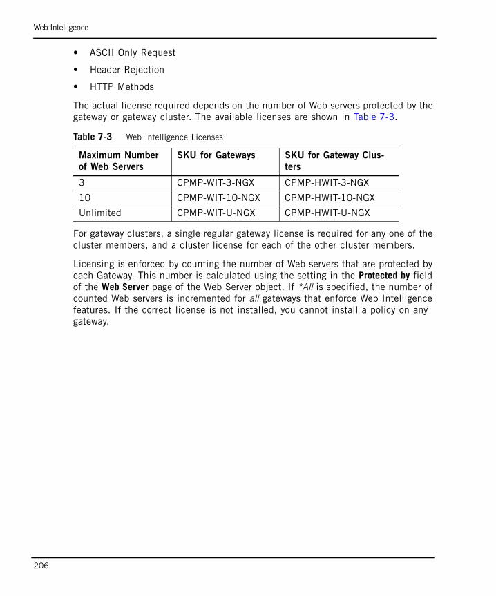
Web Intelligence
206
• ASCII Only Request
• Header Rejection
• HTTP Methods
The actual license required depends on the number of Web servers protected by the gateway or gateway cluster. The available licenses are shown in Table 7-3.
For gateway clusters, a single regular gateway license is required for any one of the cluster members, and a cluster license for each of the other cluster members.
Licensing is enforced by counting the number of Web servers that are protected by each Gateway. This number is calculated using the setting in the Protected by field of the Web Server page of the Web Server object. If *All is specified, the number of counted Web servers is incremented for all gateways that enforce Web Intelligence features. If the correct license is not installed, you cannot install a policy on any gateway.
Table 7-3 Web Intelligence Licenses
Maximum Number
of Web Servers
SKU for Gateways SKU for Gateway Clus-
ters
3 CPMP-WIT-3-NGX CPMP-HWIT-3-NGX
10 CPMP-WIT-10-NGX CPMP-HWIT-10-NGX
Unlimited CPMP-WIT-U-NGX CPMP-HWIT-U-NGX
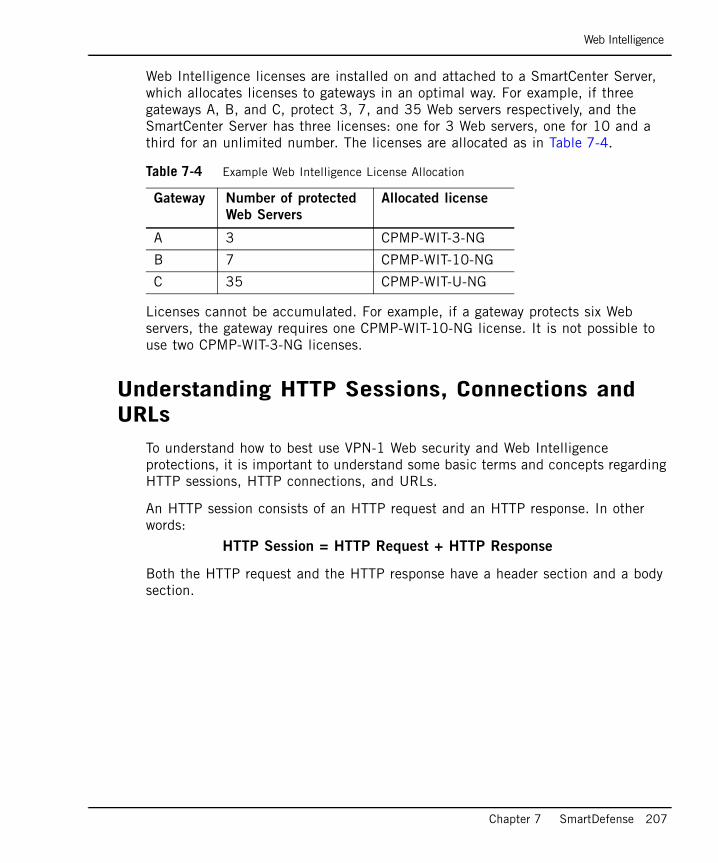
Web Intelligence
Chapter 7 SmartDefense 207
Web Intelligence licenses are installed on and attached to a SmartCenter Server, which allocates licenses to gateways in an optimal way. For example, if three gateways A, B, and C, protect 3, 7, and 35 Web servers respectively, and the SmartCenter Server has three licenses: one for 3 Web servers, one for 10 and a third for an unlimited number. The licenses are allocated as in Table 7-4.
Licenses cannot be accumulated. For example, if a gateway protects six Web servers, the gateway requires one CPMP-WIT-10-NG license. It is not possible to use two CPMP-WIT-3-NG licenses.
Understanding HTTP Sessions, Connections and URLs
To understand how to best use VPN-1 Web security and Web Intelligence protections, it is important to understand some basic terms and concepts regarding HTTP sessions, HTTP connections, and URLs.
An HTTP session consists of an HTTP request and an HTTP response. In other words:
HTTP Session = HTTP Request + HTTP Response
Both the HTTP request and the HTTP response have a header section and a body section.
Table 7-4 Example Web Intelligence License Allocation
Gateway Number of protected
Web Servers
Allocated license
A 3 CPMP-WIT-3-NG
B 7 CPMP-WIT-10-NG
C 35 CPMP-WIT-U-NG
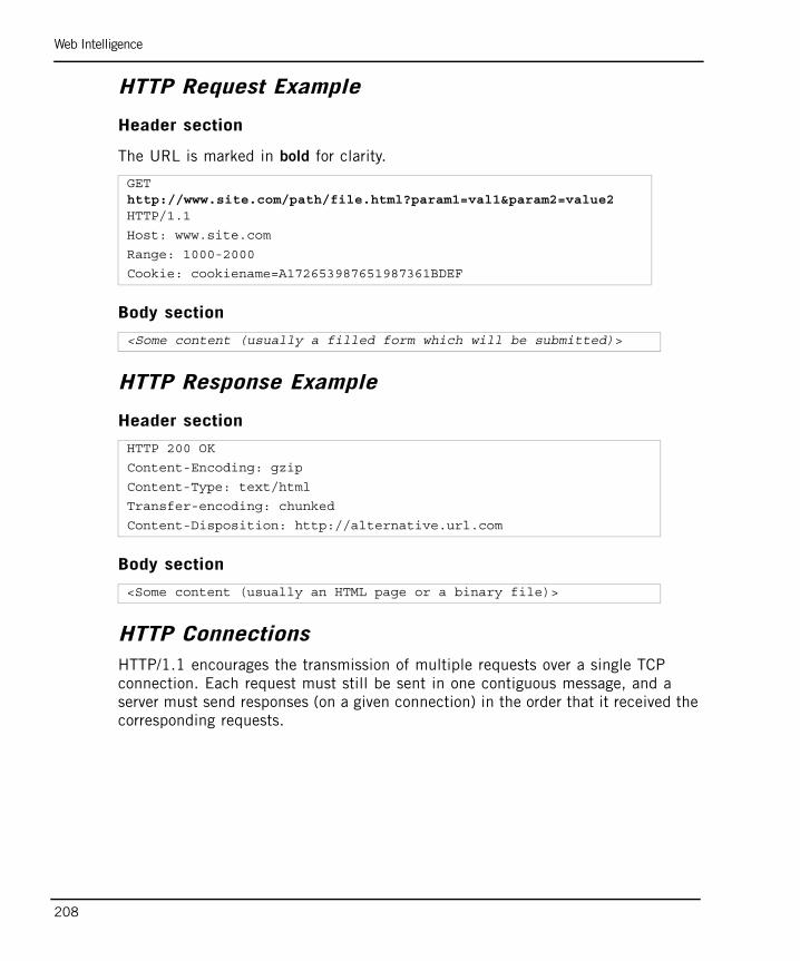
Web Intelligence
208
HTTP Request Example
Header section
The URL is marked in bold for clarity.
Body section
HTTP Response Example
Header section
Body section
HTTP ConnectionsHTTP/1.1 encourages the transmission of multiple requests over a single TCP connection. Each request must still be sent in one contiguous message, and a server must send responses (on a given connection) in the order that it received the corresponding requests.
GET http://www.site.com/path/file.html?param1=val1¶m2=value2 HTTP/1.1
Host: www.site.com
Range: 1000-2000
Cookie: cookiename=A172653987651987361BDEF
<Some content (usually a filled form which will be submitted)>
HTTP 200 OK
Content-Encoding: gzip
Content-Type: text/html
Transfer-encoding: chunked
Content-Disposition: http://alternative.url.com
<Some content (usually an HTML page or a binary file)>
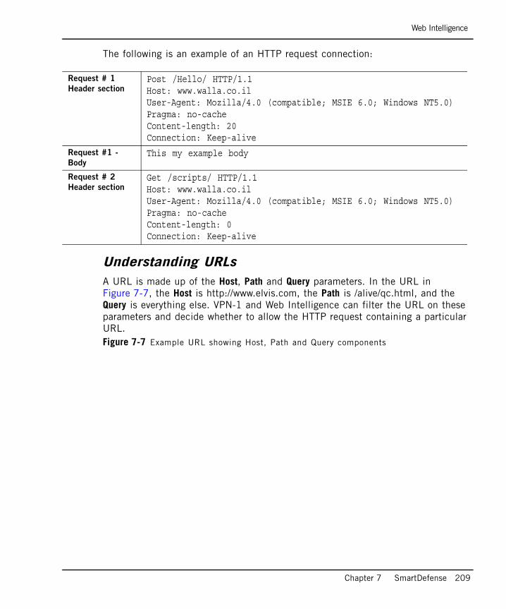
Web Intelligence
Chapter 7 SmartDefense 209
The following is an example of an HTTP request connection:
Understanding URLsA URL is made up of the Host, Path and Query parameters. In the URL in Figure 7-7, the Host is http://www.elvis.com, the Path is /alive/qc.html, and the Query is everything else. VPN-1 and Web Intelligence can filter the URL on these parameters and decide whether to allow the HTTP request containing a particular URL. Figure 7-7 Example URL showing Host, Path and Query components
Request # 1
Header sectionPost /Hello/ HTTP/1.1Host: www.walla.co.ilUser-Agent: Mozilla/4.0 (compatible; MSIE 6.0; Windows NT5.0)Pragma: no-cacheContent-length: 20Connection: Keep-alive
Request #1 -
BodyThis my example body
Request # 2
Header sectionGet /scripts/ HTTP/1.1Host: www.walla.co.ilUser-Agent: Mozilla/4.0 (compatible; MSIE 6.0; Windows NT5.0)Pragma: no-cacheContent-length: 0Connection: Keep-alive
Configuring SmartDefense
210
Configuring SmartDefenseTo configure SmartDefense:
1. In the SmartDashboard window, click the SmartDefense tab. The SmartDefense Settings window opens.
2. In the SmartDefense Settings window, select the SmartDefense category you want to view information on.
3. To view details of a specific attack, click [+] to expand the branch and then select the attack.
4. Select the attacks you want to defend against and select Settings to configure the categories and the specific attacks.
5. Install the security policy. You need to reinstall the security policy in order to implement changes to the SmartDefense configuration.
Updating SmartDefense with the Latest DefensesTo obtain updates of all the latest defenses from the SmartDefense website:
• Access the SmartDefense Settings > General page, and click Update SmartDefense.
SmartDefense Services
Chapter 7 SmartDefense 211
SmartDefense ServicesFrom the SmartDefense Services tab, you can update all available products from a central location. The Services tab contains the following three views:
• Download Updates
• Advisories
• Security Best Practices
Download UpdatesFrom the Download Updates tab, you can review information on updates available for download. Each entry in the table describes the following update packages:
• VPN-1 Includes SmartDefense and Web Intelligence updates for the following network objects:
• VPN-1 Power/UTM gateways
• VPN-1 Power/UTM clusters
• VPN-1 UTM Edge or Embedded gateways
• VPN-1 Power VSX gateways
• VPN-1 Power VSX clusters
• InterSpect 1.x and 2.0: Describes SmartDefense and Web Intelligence updates for centrally managed InterSpect gateways of versions 1.0, 1.1, 1.5 and 2.0. This entry appears only if the gateways are defined in SmartDashboard.
• InterSpect NGX: Describes SmartDefense and Web Intelligence updates for centrally managed InterSpect gateways of version NGX. This entry appears only if the gateways are defined in SmartDashboard.
• Connectra 2.0: Describes SmartDefense and Web Intelligence updates for centrally managed Connectra gateways of version 2.0. This entry appears only if the gateways are defined in SmartDashboard.
• Connectra NGX: Describes SmartDefense and Web Intelligence updates for centrally managed Connectra gateways of version NGX. This entry appears only if the gateways are defined in SmartDashboard.
• CI: Describes manual signature updates for gateways that are Anti Virus installed. To implement this, ensure that Anti Virus is selected in the Check Point Products list in the General Properties page of the gateway. This entry appears only if the gateways are defined in SmartDashboard.
SmartDefense Services
212
• VPN-1 UTM Edge CI: Describes manual signature updates for VPN-1 UTM Edge gateways that are Anti Virus installed, these are defined on the Content Filtering page of the gateway. This entry appears only if the gateways are defined in SmartDashboard.
The following Downloads Update table columns provide detailed information on each update:
1. Last Downloaded Update: Displays the update that is currently downloaded in SmartCenter. When you click on the link, the highlights of the currently installed update are displayed. (For the CI entries, such information does not exist.)
2. Available New Update: Displays the latest available update on the download center. When you click on the link, the highlights of the newest update are displayed. (For the CI entries, such information does not exist.)
3. Deployment Status: Shows which updated version is installed for each gateway, as well as one of the following gateway statuses:
• Up to date: The gateway has the latest available update installed.
• Out of date: The gateway does not have the latest update installed.
• Not available: There is no update currently installed on the gateway.
AdvisoriesFrom the Advisories tab, you can view detailed descriptions of SmartDefense updates and step-by-step instructions on how to activate and configure them.
To view advisories, do one of the following:
• If the administrator is not logged in to the UserCenter, click in the Check Point Reference column to view a vulnerability description.
• If the administrator is logged in to the UserCenter (through the Log in to UserCenter link located at the top of the page), a full step-by-step solution to the described attacks is provided.

SmartDefense Services
Chapter 7 SmartDefense 213
Security Best PracticesFrom the Security Best Practices tab, you can view Check Point’s latest security recommendations briefs.
Similar to the Advisories tab, this view also has two states: one when the administrator is logged in, and the other when the administrator is not logged in (for additional information, refer to “Advisories” on page 212).
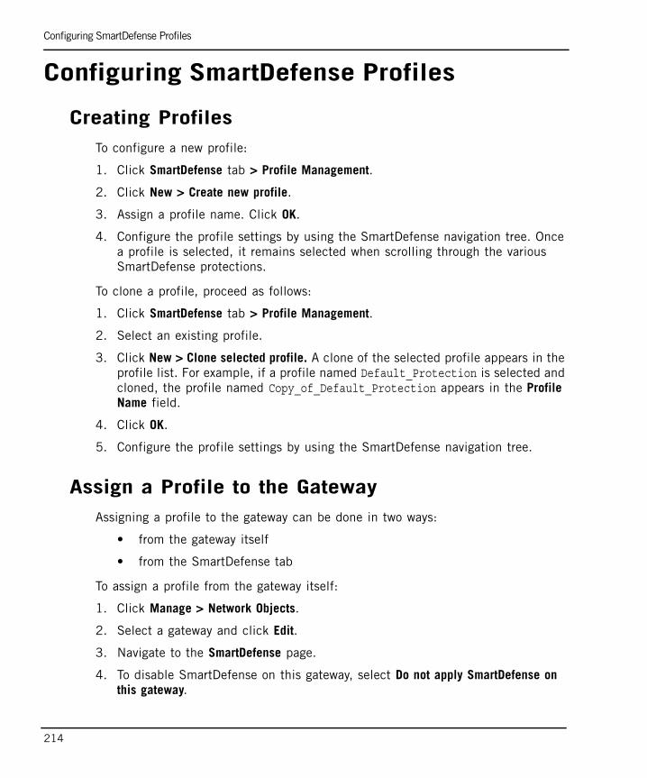
Configuring SmartDefense Profiles
214
Configuring SmartDefense Profiles
Creating ProfilesTo configure a new profile:
1. Click SmartDefense tab > Profile Management.
2. Click New > Create new profile.
3. Assign a profile name. Click OK.
4. Configure the profile settings by using the SmartDefense navigation tree. Once a profile is selected, it remains selected when scrolling through the various SmartDefense protections.
To clone a profile, proceed as follows:
1. Click SmartDefense tab > Profile Management.
2. Select an existing profile.
3. Click New > Clone selected profile. A clone of the selected profile appears in the profile list. For example, if a profile named Default_Protection is selected and cloned, the profile named Copy_of_Default_Protection appears in the Profile Name field.
4. Click OK.
5. Configure the profile settings by using the SmartDefense navigation tree.
Assign a Profile to the GatewayAssigning a profile to the gateway can be done in two ways:
• from the gateway itself
• from the SmartDefense tab
To assign a profile from the gateway itself:
1. Click Manage > Network Objects.
2. Select a gateway and click Edit.
3. Navigate to the SmartDefense page.
4. To disable SmartDefense on this gateway, select Do not apply SmartDefense on this gateway.
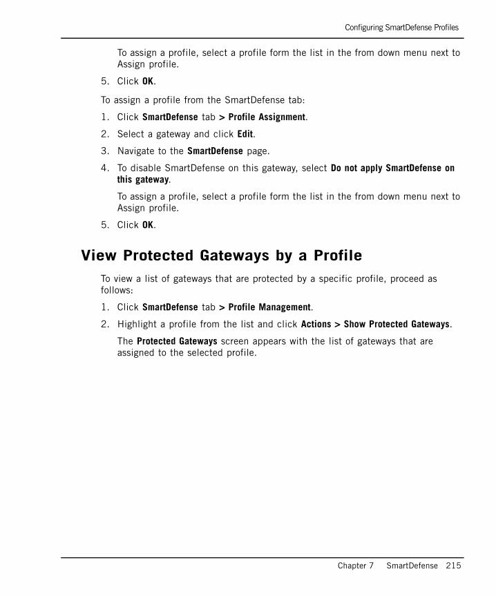
Configuring SmartDefense Profiles
Chapter 7 SmartDefense 215
To assign a profile, select a profile form the list in the from down menu next to Assign profile.
5. Click OK.
To assign a profile from the SmartDefense tab:
1. Click SmartDefense tab > Profile Assignment.
2. Select a gateway and click Edit.
3. Navigate to the SmartDefense page.
4. To disable SmartDefense on this gateway, select Do not apply SmartDefense on this gateway.
To assign a profile, select a profile form the list in the from down menu next to Assign profile.
5. Click OK.
View Protected Gateways by a ProfileTo view a list of gateways that are protected by a specific profile, proceed as follows:
1. Click SmartDefense tab > Profile Management.
2. Highlight a profile from the list and click Actions > Show Protected Gateways.
The Protected Gateways screen appears with the list of gateways that are assigned to the selected profile.
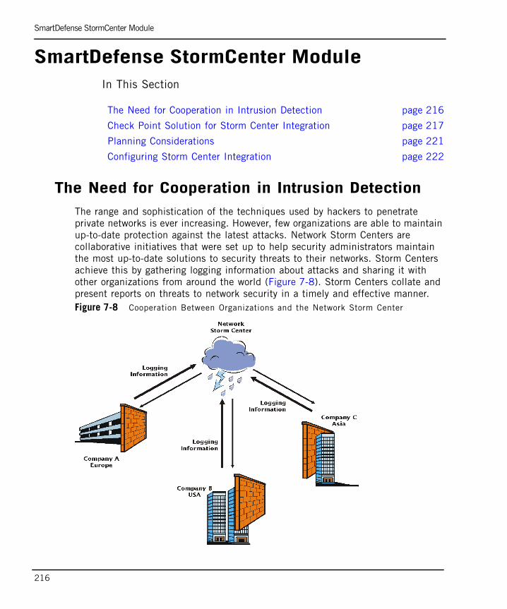
SmartDefense StormCenter Module
216
SmartDefense StormCenter ModuleIn This Section
The Need for Cooperation in Intrusion DetectionThe range and sophistication of the techniques used by hackers to penetrate private networks is ever increasing. However, few organizations are able to maintain up-to-date protection against the latest attacks. Network Storm Centers are collaborative initiatives that were set up to help security administrators maintain the most up-to-date solutions to security threats to their networks. Storm Centers achieve this by gathering logging information about attacks and sharing it with other organizations from around the world (Figure 7-8). Storm Centers collate and present reports on threats to network security in a timely and effective manner. Figure 7-8 Cooperation Between Organizations and the Network Storm Center
The Need for Cooperation in Intrusion Detection page 216
Check Point Solution for Storm Center Integration page 217
Planning Considerations page 221
Configuring Storm Center Integration page 222
SmartDefense StormCenter Module
Chapter 7 SmartDefense 217
Check Point Solution for Storm Center Integration
In This Section
IntroductionThe SmartDefense Storm Center module is included in the standard VPN-1 product installation. It enables two-way information flow between the Network Storm Centers and the organizations requiring network security information.
One of the leading Storm Centers is SANS DShield.org, located at: http://www.dshield.org/. DShield.org gathers statistics and presents it as a series of reports at http://www.dshield.org/reports.html.
SmartDefense integrates with the SANS DShield.org Storm Center in the following two ways (Figure 7-9):
• The DShield.org Storm Center produces a Block List report, which is a frequently updated list of address ranges that are recommended for blocking. The SmartDefense Storm Center module retrieves and adds this list to the security policy.
• The Storm Center sends logs to other organizations in order to help them combat threats that were directed at your network. To send logs, select the Security Rules and SmartDefense/Web Intelligence protections for which you want to send logs.
Introduction page 217
How the Block List is Received page 218
How Logs Are Submitted to the Storm Center page 219
What a Submitted Log Contains page 220
Removing Identifying Information from the Submitted Log page 220
How Authenticity is Assured page 221
Log Size and Effect on VPN-1 Performance page 221
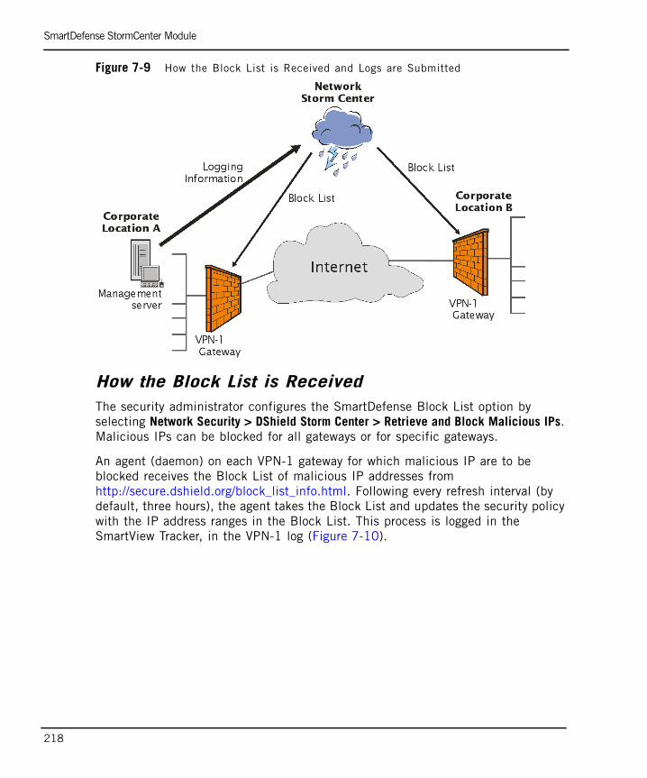
SmartDefense StormCenter Module
218
Figure 7-9 How the Block List is Received and Logs are Submitted
How the Block List is Received The security administrator configures the SmartDefense Block List option by selecting Network Security > DShield Storm Center > Retrieve and Block Malicious IPs. Malicious IPs can be blocked for all gateways or for specific gateways.
An agent (daemon) on each VPN-1 gateway for which malicious IP are to be blocked receives the Block List of malicious IP addresses from http://secure.dshield.org/block_list_info.html. Following every refresh interval (by default, three hours), the agent takes the Block List and updates the security policy with the IP address ranges in the Block List. This process is logged in the SmartView Tracker, in the VPN-1 log (Figure 7-10).
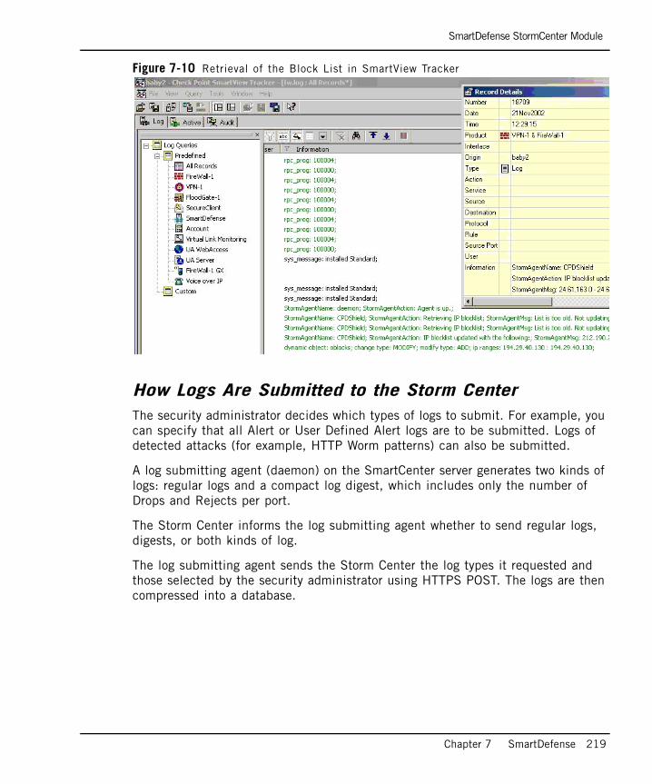
SmartDefense StormCenter Module
Chapter 7 SmartDefense 219
Figure 7-10 Retrieval of the Block List in SmartView Tracker
How Logs Are Submitted to the Storm CenterThe security administrator decides which types of logs to submit. For example, you can specify that all Alert or User Defined Alert logs are to be submitted. Logs of detected attacks (for example, HTTP Worm patterns) can also be submitted.
A log submitting agent (daemon) on the SmartCenter server generates two kinds of logs: regular logs and a compact log digest, which includes only the number of Drops and Rejects per port.
The Storm Center informs the log submitting agent whether to send regular logs, digests, or both kinds of log.
The log submitting agent sends the Storm Center the log types it requested and those selected by the security administrator using HTTPS POST. The logs are then compressed into a database.

SmartDefense StormCenter Module
220
What a Submitted Log ContainsThe logs that are submitted to the Storm Center contain the following information:
• Connection Parameters: Source IP Address, Destination IP Address, Source Port, Destination Port (the Service) and IP protocol (for example, UDP, TCP or ICMP)
• Rule Base Parameters: Time and action
• Detailed Log Description
For HTTP Worm patterns, the log contains the same connection and Rule Base parameters as well as the name of the attack and the detected URL pattern.
The logs are submitted as SmartDefense logs in SmartView Tracker (Figure 7-11).Figure 7-11 The submission of Logs to the Storm Center in SmartView Tracker
Removing Identifying Information from the Submitted LogYou can delete identifying information from internal IP addresses in the submitted log by defining a designated number of bits to mask.
The mask is used to delete as many bits as you want from the internal IP addresses. A zero bit mask obscures the whole IP address and a 32 bit mask reveals the whole internal IP address. An 8 bit mask reveals 8 valid bits and converts the IP address 192.168.46.88 to 0.0.0.88.
SmartDefense StormCenter Module
Chapter 7 SmartDefense 221
How Authenticity is AssuredThe Block List and the submitted logs are securely transferred and authenticated through SSL. The Certificate of the Storm Center Certificate Authority, which comes with the Storm Center module, is stored locally and serves the following purposes:
• To verify the authenticity of the origin of the received Block List.
• To establish an SSL connection with the Storm Center when submitting logs, while assuring that the logs are sent only to the Storm Center.
The Certificate Authority of SANS DShield.org is Equifax. equifax.cer is the file name of the locally stored certificate, which is stored in the conf directory of the Storm Center module installation.
To send logs to DShield.org, you must first register with them. DShield.org authenticates log submitters with a username and password that is obtained upon registration.
Log Size and Effect on VPN-1 PerformanceReceiving the Block List does not effect VPN-1 performance because only a very small amount of data is received. The submitted log is compressed and makes up a small subset of the complete SmartDefense log. The size of the log depends on the log interval and the maximum size of the log database (for example, approximately 10,000 lines of logs take up 200 KB).
Planning Considerations
Which Logs to Send to the Storm Center Storm Centers are generally interested in receiving logging information on:
• Unwanted port 80 traffic that reaches the organization.
• The Drop All rule (the last Rule in the Rule Base), which drops all traffic that is not explicitly allowed by previous rules.
• Logs generated by the blocking of malicious IP addresses.
• SmartDefense and Web Intelligence protections.
Which Logs NOT to Send to the Storm CenterIt is not recommended to send logs generated by rules that log internal traffic.
SmartDefense StormCenter Module
222
Which Identifying Information to Remove from Submitted LogsFirst decide which of your organization IP addresses that you want to obscure from the submitted logs. If all your internal addresses are private, nonroutable addresses, it may not be necessary to mask the addresses. However, you should keep in mind that even nonroutable addresses can reveal information about your internal network topology.
Configuring Storm Center Integration
Retrieving and Blocking Malicious IPsTo retrieve and block malicious IPs:
1. In the Security Rule Base, define appropriate rules as necessary. Gateways and SmartCenter servers must be able to connect to the Storm Center using HTTPS.
2. In SmartDefense, select Network Security > DShield Storm Center > Retrieve and Block Malicious IPs.
3. Configure the required settings. You can block connections from IP addresses in the Block List at all gateways or at selected gateways.
4. If you are also submitting logs to DShield and want to report logs generated by blocking malicious IP addresses, ensure that the Track setting is identical to the Submit Logs of Type setting in the SmartDefense DShield Storm Center > Report to DShield section.
5. Install the security policy.
Manually Configuring the Blocking of Malicious IPsWhen configured through SmartDefense, the DShield Block List is enforced before the Rule Base. Because DShield uses statistical analysis and the Block List is made up of /24 (Class C) networks, not all of those IP addresses are necessarily malicious. Therefore, in order to prevent reputable IP addresses from being blocked, you can manually add a Block List rule in the Security Rule Base.
Note - Ensure that the Block List is enforced on perimeter gateways ONLY.
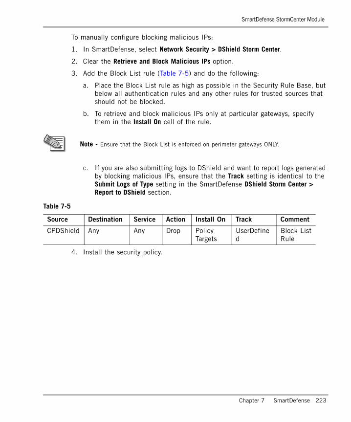
SmartDefense StormCenter Module
Chapter 7 SmartDefense 223
To manually configure blocking malicious IPs:
1. In SmartDefense, select Network Security > DShield Storm Center.
2. Clear the Retrieve and Block Malicious IPs option.
3. Add the Block List rule (Table 7-5) and do the following:
a. Place the Block List rule as high as possible in the Security Rule Base, but below all authentication rules and any other rules for trusted sources that should not be blocked.
b. To retrieve and block malicious IPs only at particular gateways, specify them in the Install On cell of the rule.
c. If you are also submitting logs to DShield and want to report logs generated by blocking malicious IPs, ensure that the Track setting is identical to the Submit Logs of Type setting in the SmartDefense DShield Storm Center > Report to DShield section.
4. Install the security policy.
Note - Ensure that the Block List is enforced on perimeter gateways ONLY.
Table 7-5
Source Destination Service Action Install On Track Comment
CPDShield Any Any Drop Policy Targets
UserDefined
Block ListRule
SmartDefense StormCenter Module
224
Submitting Logs to DShield.orgTo submit logs to DSheild.org:
1. To submit logs to DShield.org, first register at: http://www.dshield.org/register.html. You receive a DShield username and password. (You can receive the Block List without registering.)
2. To view DShield reports and statistics about submitted logs, log in to DShield at: http://www.dshield.org/login.html.
3. VPN-1 gateways and SmartCenter server(s) must be able to connect to the Storm Center using HTTPS. In the Security Rule Base, define an appropriate Rule if necessary.
4. In SmartDefense, select Network Security > DShield Storm Center > Report to DShield.
5. Configure the Submit all logs of type option to determine which logs are sent to the Storm Center, for example, submit all Alert or User Defined Alert log types.
6. Set the Track option of any rule or SmartDefense/Web Intelligence protection for the logs that you want to submit.
7. Configure the Hide internal networks using this mask option to prevent the internal network topology from being exposed by the submitted logs. A 0.0.0.0 mask reveals the whole internal IP address. A 255.255.255.0 mask reveals 8 valid bits and converts the 192.168.46.88 IP address to 0.0.0.88.
8. From the gateway object Topology page, ensure that the topology is correctly defined for all gateways.
9. Install the security policy.
Application IntelligenceCheck Point Application Intelligence is a set of advanced capabilities, integrated into VPN-1 and SmartDefense, which detect and prevent application-level attacks. This section describes how to protect against application-level attacks for each application protocol, and how to work with anti-virus (CVP) and URL filtering (UFP) applications.


227
Chapter 8Content Inspection
In This Chapter
Anti Virus Protection page 228
Web Filtering page 243
Anti Virus Protection
228
Anti Virus ProtectionIn This Section
Introduction to Integrated Anti Virus ProtectionViruses are a major threat to an network operations and have become increasingly dangerous and sophisticated. For example, worms, blended threats (which use combinations of malicious code and vulnerabilities for infection and dissemination) and trojans.
VPN-1 Content Inspection (CI) gateways contain integrated Anti Virus technology. Integrated Anti Virus solutions require no extra IT resources and organizations benefit from their easy management in the familiar Check Point SMART infrastructure, which includes policy management, logging and monitoring. As a single box solution, hardware management is also simplified.
Anti Virus protection is available for the HTTP, FTP, SMTP and POP3 protocols. By default, all protocols are scanned and options for each protocol can be centrally configured.
Introduction to Integrated Anti Virus Protection page 228
Architecture page 229
Configuring Integrated Anti Virus Scanning page 229
Database Updates page 230
Understanding Scan By Direction and Scan By IP page 231
Scanning by Direction: Selecting Data to Scan page 235
File Type Recognition page 237
Continuous Download page 238
Logging and Monitoring page 239
File Size Limitations and Scanning page 240
VPN-1 UTM Edge Anti Virus page 242
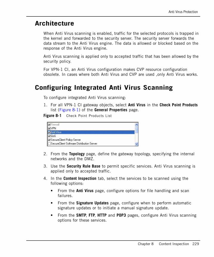
Anti Virus Protection
Chapter 8 Content Inspection 229
ArchitectureWhen Anti Virus scanning is enabled, traffic for the selected protocols is trapped in the kernel and forwarded to the security server. The security server forwards the data stream to the Anti Virus engine. The data is allowed or blocked based on the response of the Anti Virus engine.
Anti Virus scanning is applied only to accepted traffic that has been allowed by the security policy.
For VPN-1 CI, an Anti Virus configuration makes CVP resource configuration obsolete. In cases where both Anti Virus and CVP are used ,only Anti Virus works.
Configuring Integrated Anti Virus ScanningTo configure integrated Anti Virus scanning:
1. For all VPN-1 CI gateway objects, select Anti Virus in the Check Point Products list (Figure 8-1) of the General Properties page.
Figure 8-1 Check Point Products List
2. From the Topology page, define the gateway topology, specifying the internal networks and the DMZ.
3. Use the Security Rule Base to permit specific services. Anti Virus scanning is applied only to accepted traffic.
4. In the Content Inspection tab, select the services to be scanned using the following options:
• From the Anti Virus page, configure options for file handling and scan failures.
• From the Signature Updates page, configure when to perform automatic signature updates or to initiate a manual signature update.
• From the SMTP, FTP, HTTP and POP3 pages, configure Anti Virus scanning options for these services.
Anti Virus Protection
230
• From the File Types page, configure whether to Scan, Block or Pass traffic according to the file type and configure continuous Download settings.
Database UpdatesThe following kinds of database updates are available:
• Automatic: Updates of the virus signature can be scheduled at a predefined interval.
• Manual: Updates of virus signatures can be initiated at any time.
When using the CI gateway and/or the SmartCenter server, download updates from a Check Point server prior to downloading signature updates. First verify that:
• HTTP and HTTPs Internet connectivity with DNS is properly configured.
• You have a valid Check Point User Center username and password.
The following signature update methods are available (the default update interval is 120 minutes for all methods):
• Download signature updates every x minutes: Enables you to define the update interval.
• Download from Check Point site: Indicates that each VPN-1 gateway is responsible for contacting Check Point’s site to obtain Anti Virus signatures. Updates are downloaded directly to the CI gateways. This method usually results in faster update times.
• Download from My local SmartCenter Server: Indicates that updates are only downloaded by the SmartCenter server from the default Check Point signature distribution server and then redistributed all VPN-1 CI gateways. This method is useful when Internet access is not available for all gateways or if the download can only occur once for all the gateways.

Anti Virus Protection
Chapter 8 Content Inspection 231
Understanding Scan By Direction and Scan By IP
In This Section
DefinitionsScan by Direction and Scan by IP are two file scanning methods used by Content Inspection. Anti Virus scanning is performed only on traffic that is allowed by the Security Rule Base.
Scan By Direction
Scan by Direction scans all files passing in one direction, either to or from the external, internal and/or DMZ networks. Using this method (the default) is fairly intuitive and does not require the specification of hosts or networks. This method also enables you to define exceptions, for example, locations to or from which files are not scanned.
Scan By IP Address
Scan by IP address enables you to define which traffic is scanned. For example, if all incoming traffic from external networks reaches the DMZ using Scan by IP, you can configure CE to scan only traffic to the FTP, SMTP, HTTP and POP3 servers. Conversely, Scan by Direction scans all traffic to the DMZ.
When using Scan by IP address, use a Rule Base to specify the source and destination of the data to be scanned. For FTP, for each rule, you can scan either the GET or the PUT methods, or both. For HTTP, for each rule, you can scan either the HTTP Request, the HTTP Response or both.
Definitions page 231
Comparing Scan by Direction and by IP page 232
Note - Scan By Direction works only when CI is connected as a gateway and is placed in line between the external and the internal/DMZ networks. It does not work when VPN-1 CI is connected as a node in Proxy mode. The gateway topology must also be correctly defined.
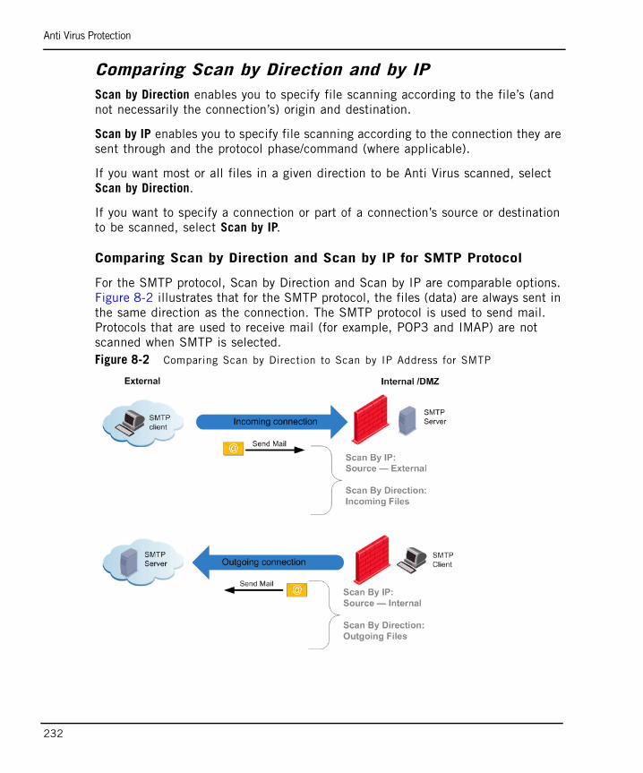
Anti Virus Protection
232
Comparing Scan by Direction and by IPScan by Direction enables you to specify file scanning according to the file’s (and not necessarily the connection’s) origin and destination.
Scan by IP enables you to specify file scanning according to the connection they are sent through and the protocol phase/command (where applicable).
If you want most or all files in a given direction to be Anti Virus scanned, select Scan by Direction.
If you want to specify a connection or part of a connection’s source or destination to be scanned, select Scan by IP.
Comparing Scan by Direction and Scan by IP for SMTP Protocol
For the SMTP protocol, Scan by Direction and Scan by IP are comparable options. Figure 8-2 illustrates that for the SMTP protocol, the files (data) are always sent in the same direction as the connection. The SMTP protocol is used to send mail. Protocols that are used to receive mail (for example, POP3 and IMAP) are not scanned when SMTP is selected. Figure 8-2 Comparing Scan by Direction to Scan by IP Address for SMTP
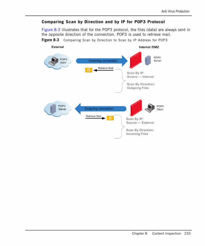
Anti Virus Protection
Chapter 8 Content Inspection 233
Comparing Scan by Direction and by IP for POP3 Protocol
Figure 8-3 illustrates that for the POP3 protocol, the files (data) are always sent in the opposite direction of the connection. POP3 is used to retrieve mail. Figure 8-3 Comparing Scan by Direction to Scan by IP Address for POP3
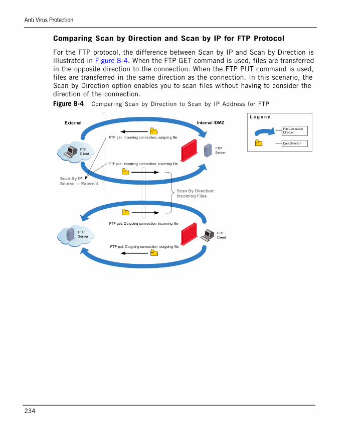
Anti Virus Protection
234
Comparing Scan by Direction and Scan by IP for FTP Protocol
For the FTP protocol, the difference between Scan by IP and Scan by Direction is illustrated in Figure 8-4. When the FTP GET command is used, files are transferred in the opposite direction to the connection. When the FTP PUT command is used, files are transferred in the same direction as the connection. In this scenario, the Scan by Direction option enables you to scan files without having to consider the direction of the connection. Figure 8-4 Comparing Scan by Direction to Scan by IP Address for FTP
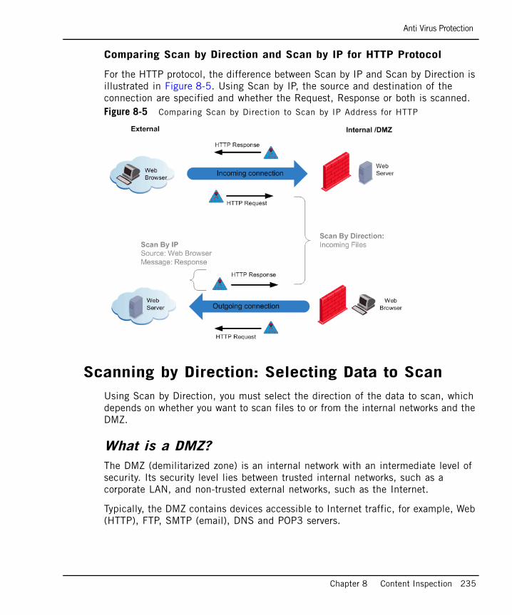
Anti Virus Protection
Chapter 8 Content Inspection 235
Comparing Scan by Direction and Scan by IP for HTTP Protocol
For the HTTP protocol, the difference between Scan by IP and Scan by Direction is illustrated in Figure 8-5. Using Scan by IP, the source and destination of the connection are specified and whether the Request, Response or both is scanned. Figure 8-5 Comparing Scan by Direction to Scan by IP Address for HTTP
Scanning by Direction: Selecting Data to ScanUsing Scan by Direction, you must select the direction of the data to scan, which depends on whether you want to scan files to or from the internal networks and the DMZ.
What is a DMZ?The DMZ (demilitarized zone) is an internal network with an intermediate level of security. Its security level lies between trusted internal networks, such as a corporate LAN, and non-trusted external networks, such as the Internet.
Typically, the DMZ contains devices accessible to Internet traffic, for example, Web (HTTP), FTP, SMTP (email), DNS and POP3 servers.
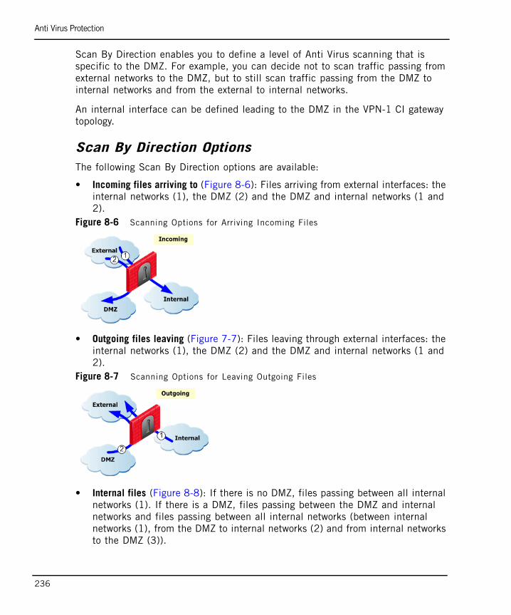
Anti Virus Protection
236
Scan By Direction enables you to define a level of Anti Virus scanning that is specific to the DMZ. For example, you can decide not to scan traffic passing from external networks to the DMZ, but to still scan traffic passing from the DMZ to internal networks and from the external to internal networks.
An internal interface can be defined leading to the DMZ in the VPN-1 CI gateway topology.
Scan By Direction OptionsThe following Scan By Direction options are available:
• Incoming files arriving to (Figure 8-6): Files arriving from external interfaces: the internal networks (1), the DMZ (2) and the DMZ and internal networks (1 and 2).
Figure 8-6 Scanning Options for Arriving Incoming Files
• Outgoing files leaving (Figure 7-7): Files leaving through external interfaces: the internal networks (1), the DMZ (2) and the DMZ and internal networks (1 and 2).
Figure 8-7 Scanning Options for Leaving Outgoing Files
• Internal files (Figure 8-8): If there is no DMZ, files passing between all internal networks (1). If there is a DMZ, files passing between the DMZ and internal networks and files passing between all internal networks (between internal networks (1), from the DMZ to internal networks (2) and from internal networks to the DMZ (3)).
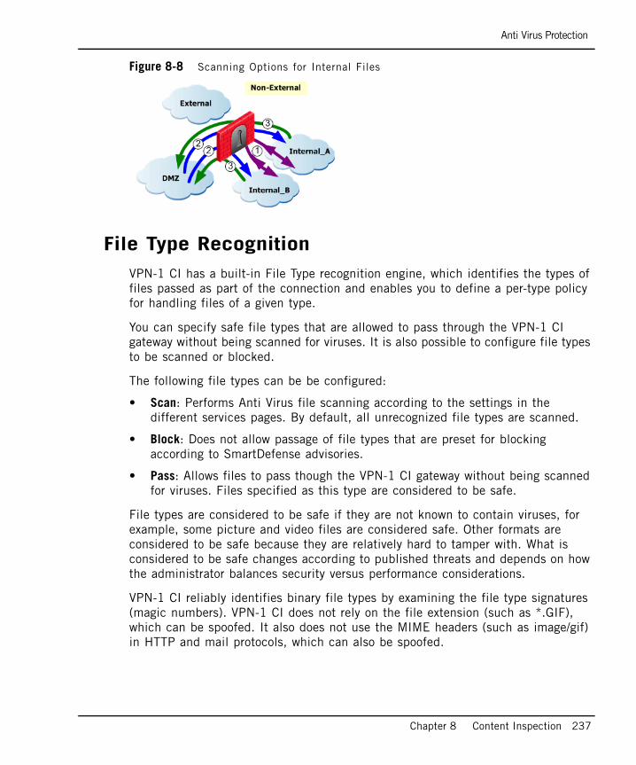
Anti Virus Protection
Chapter 8 Content Inspection 237
Figure 8-8 Scanning Options for Internal Files
File Type RecognitionVPN-1 CI has a built-in File Type recognition engine, which identifies the types of files passed as part of the connection and enables you to define a per-type policy for handling files of a given type.
You can specify safe file types that are allowed to pass through the VPN-1 CI gateway without being scanned for viruses. It is also possible to configure file types to be scanned or blocked.
The following file types can be be configured:
• Scan: Performs Anti Virus file scanning according to the settings in the different services pages. By default, all unrecognized file types are scanned.
• Block: Does not allow passage of file types that are preset for blocking according to SmartDefense advisories.
• Pass: Allows files to pass though the VPN-1 CI gateway without being scanned for viruses. Files specified as this type are considered to be safe.
File types are considered to be safe if they are not known to contain viruses, for example, some picture and video files are considered safe. Other formats are considered to be safe because they are relatively hard to tamper with. What is considered to be safe changes according to published threats and depends on how the administrator balances security versus performance considerations.
VPN-1 CI reliably identifies binary file types by examining the file type signatures (magic numbers). VPN-1 CI does not rely on the file extension (such as *.GIF), which can be spoofed. It also does not use the MIME headers (such as image/gif) in HTTP and mail protocols, which can also be spoofed.
Anti Virus Protection
238
Continuous DownloadThe Anti Virus engine acts as a proxy which caches the scanned file before delivering it to the client for files that need to be scanned.
When scanning large files, if the whole file is scanned before being made available, the user may experience a long delay before the file is delivered. A similar problem may arise when using client applications with short timeout periods (for example, certain FTP clients) to download large files. If the whole file is cached and scanned before being delivered, the client applications may time out while waiting.
To address this problem, Continuous Download starts sending information to the client while Anti Virus scanning is still taking place. If a virus is found during the scan, file delivery to the client is terminated.
You can specify the file types for which you do not want Continuous Download to occur. Some file types (for example, Adobe Acrobat PDF and Microsoft Power Point files) can open on a client computer before the whole file has been downloaded. If Continuous Download is allowed for those file types, and a virus is present in the opened part of the file, it could infect the client computer.
Note - The SMTP and POP3 protocols support Continuous Download for the entire email message.
Anti Virus Protection
Chapter 8 Content Inspection 239
Logging and MonitoringLogging information on the Anti Virus scan is sent to the SmartCenter server and can be viewed using SmartView Tracker. Scan results information is shown in the logs. In addition, there are logs for signature updates, new update checks, and download results.
The Anti Virus status is monitored using SmartView Monitor. The Anti Virus status appears under the Firewall-1 product. The status contains information on the currently installed signature file and the Anti Virus engine version. The Anti Virus status also includes statistics about scanned files and found viruses.

Anti Virus Protection
240
File Size Limitations and Scanning
General SettingsThe default settings in the Anti Virus window have been configured to prevent the Anti Virus engine from overloading. It is recommended that you use the default settings provided.
If the Anti Virus engine becomes overloaded, use the options in the Anti Virus window to determine:
• Whether to allow files that have not been scanned to pass. Selecting this option leaves you open to virus attacks.
• Whether to block all files. Selecting this option may result in connectivity problems.
File HandlingThe following file handling options are available:
• Maximum file size to scan: Limits the file size that is allowed to pass through the gateway. If the file is a compressed archive, the limit applies to the file after decompression (the Anti Virus engine decompresses archives before scanning them). Before performing Anti Virus scanning, the gateway reassembles the entire file and then scans it. The limit protects the gateway resources and the destination client.An archive is a file that contains one or more files in a compressed format. Archives (and all other file types) are recognized by their binary signature. By default, any file type that is not identified as non-archive is assumed to be an archive and the Anti Virus engine tries to expand it.
• When file exceeds limit: Determines whether to scan or block the file.
Note - An email is treated as an archive and as a result it is not affected when the file exceeds the limit.
Anti Virus Protection
Chapter 8 Content Inspection 241
Archive File HandlingThe following file handling archiving options are available:
• Maximum archive nesting level: Limits the number of nested archives (one within another). This limit protects the gateway and destination client from attacks that employ deep nesting levels.
• Maximum compression ratio: Prevents attacks that employ a small size archive that decompresses into a very large file on target.
• When archive file exceeds limit or extraction fails: Determines whether to scan or block the file.
Scan FailureThe following scan failure options are available:
• When Anti Virus engine is overloaded or scan fails: Determines whether to scan or block the file.
• When Anti Virus engine fails to initialize: Determines whether to scan or block the file.
Anti Virus Protection
242
VPN-1 UTM Edge Anti VirusYou can now enable Anti Virus protection within VPN-1 UTM Edge. Selecting the Anti Virus Protection enabled option indicates that Anti Virus protection is installed and that updates are sent to the specified gateway.
Using VPN-1 UTM Edge Anti Virus, you can define the maximum archive file sizes for VPN-1 UTM Edge machines that are scanned, and configure procedures for when these limits are exceeded and/or the scan fails.
The VPN-1 UTM Edge Anti Virus feature enables you to automatically or manually update virus signatures for VPN-1 UTM Edge machines and provides you with the tools to configure how VPN-1 UTM Edge traffic is scanned.
The VPN-1 UTM Edge Anti Virus scanning policy enables you to select the service(s) to and from which a source and/or destination is scanned. Files set for scanning is determined using a classic Rule Base, which defines the source and destination of the connection to be scanned. It is recommended to use this method if you want to define exactly which traffic to scan, for example, if all incoming traffic from external networks reaches the DMZ, you can specify that only traffic to the Anti Virus servers is scanned.
To enable and configure Anti Virus protection:
1. From the General Properties tab of the VPN-1 UTM Edge/Embedded gateway, select the Anti Virus Protection enabled option.
2. In the Edge Anti Virus section of the Content Inspection tab, configure Anti Virus to work on VPN-1 UTM Edge gateways. All of the Anti Virus settings in the Content Inspection tab do not work for VPN-1 UTM Edge machines. The Edge Anti Virus settings in the Content Inspection tab only work for VPN-1 UTM Edge machines.
Note - It is important to configure a valid DNS server address on your management and gateway in order for the signature update to work.
Web Filtering
Chapter 8 Content Inspection 243
Web FilteringIn This Section
Introduction to Web FilteringAccess to the Internet can expose your organization to a variety of security threats and negatively affect employee productivity as a result of non-work-related surfing and downloading of files.
Due to the problems associated with excessive employee web surfing, organizations are turning to Web Filtering to control employee Internet access, reduce legal liability and improve organizational security. Web Filtering enforces filtering rules based on the organization’s needs and predefined categories made up of URLs and patterns of URLs.
Web Filtering includes reporting and monitoring tools that capture and present web traffic data, providing organizations with an in-depth look at how web surfing affects their organization’s security and supports decisions regarding web surfing limitations.
A web filter is a function that screens incoming web pages to determine whether or not to display its web content. The web filter verifies the web page URL against a list of approved sites and blocks access to complete sites or pages within sites that contain objectionable material (for example, pornography, illegal software and spyware).
Introduction to Web Filtering page 243
Terminology page 244
Architecture page 244
Configuring Web Filtering page 245
Web Filtering
244
TerminologyThe following terms are used in Web Filtering applications:
• Allow List: A list of allowed URL addresses, for example, a URL in the Allow List is allowed even if it is associated with a category that is blocked.
• Block List: A list of blocked URL addresses, for example, a URL in the Block List is blocked even if it is associated with a category that is not blocked.
• Blocking Notifications: Contains the message that appears when a URL address is blocked and the URL to which a blocked URL address is redirected.
• Category: Contains a group of topics sharing a common attribute (for example, crime, education and games.
• Network Exceptions: Contains a list of connections for which Web Filtering should not be enforced.
• Web Filter: Enables you to allow or block URLs based on network connections and/or an external categorized database and local exception lists.
ArchitectureWhen a URL request arrives at a local machine, the machine checks the Network Exceptions List to determine whether to enforce the Web Filtering policy. The Web Filtering policy is activated if the connection is accepted by the Security Policy. If the Web Filtering policy is enforced, the URL header is stripped and the address is sent to the Web Filter engine.
The URL is allowed or blocked based on categories in the predefined database and/or the Web Filter Allow/Block Lists. For example, if the URL address matches two or more categories, and one of them is blocked, the URL address is denied, however, if the same address appears in the Allow List it is accepted.
The Web Filter engine is installed on VPN-1 and the categories are updated by selecting: SmartDashboard > Content Inspection > Database Updates > Web Filtering > Web Filtering Policy.
Web Filtering
Chapter 8 Content Inspection 245
Configuring Web FilteringTo configure Web Filtering:
1. For all Check Point gateway objects, from the General Properties page, select Web Filtering in the Check Point Products List to activate Web Filtering for the specific gateway.
2. In the Content Inspection tab of SmartDashboard, select Web Filtering > Web Filtering Policy.
3. From the Web Filtering page, configure the following:
a. Select one of the following Web Filtering Policy Modes:
• On: Web Filtering is active and URLs associated with blocked categories are blocked.
• Monitor: URLs associated with blocked categories are logged and not blocked.
• Off: Web Filtering is off and does not inspect URL addresses.
b. In the Enforcing Gateways window, select the gateways for which you want to activate Web Filtering. This window contains all of the gateways for which Web Filtering can and has been enforced. You can also activate Web Filtering from the General Properties page by selecting Web Filtering from the Check Point Products list of the specific gateway.
c. In the Category Selection list, select the URL categories to block.
• A green icon indicates that URLs associated with this category are allowed.
• A red icon indicates that URLs associated with this category are blocked.
d. In Track Configuration, select how to track a detected URL address. All options other than None generate a log record in SmartView Tracker.
4. Select Advanced > Allow List to add a URL and/or IP address to be allowed even if it is associated with a blocked category.
5. Select Advanced > Block List to add a URL and/or IP address to be blocked even if it is associated with an allowed category.
Web Filtering
246
6. In the Advanced area, select Network Exceptions to create a list of the networks connections through which traffic should not be inspected or in order to enforce Web Filtering on all web traffic. Network Exceptions works according to a source and destination Rule Base and does not use the Web Filtering engine.
7. In the Advanced area, select one of the following Blocking Notifications in order to notify the user when the URL request is blocked:
• Enter the message to be displayed when a URL address is blocked according to the Web Filtering policy.
• Enter the URL address to which the user is to be redirected.
247
Chapter 9Securing Voice Over IP (VoIP)
In This Chapter
The Need to Secure Voice Over IP page 248
Introduction to the Check Point Solution for Secure VoIP page 249
Control Signalling and Media Protocols page 250
VoIP Handover page 251
VoIP Application Intelligence page 253
VoIP Logging page 257
Securing SIP-Based VoIP page 259
Troubleshooting SIP page 278
Securing H.323-Based VoIP page 279
Securing MGCP-Based VoIP page 303
Securing SCCP-Based VoIP page 311
The Need to Secure Voice Over IP
248
The Need to Secure Voice Over IPMany organizations use Voice over IP (VOIP) connectivity to communicate with remote locations and to carry data, voice and video. VOIP connectivity is also used for video conferences and for other activities that provide efficiency and significant cost savings for an organization.
Voice and video traffic, like any other information on the corporate IP network, has to be protected as it enters and exits the network. Potential threats from voice and video traffic include:
• Stealing calls: The caller pretends to be someone else by registering the calls in the name of another user.
• Call hijacking: Calls intended for the recipient are redirected to the hijacker.
• Systems hacking: Hackers abuse ports opened for VoIP connections.
• Denial of Service attacks: A rogue phone floods the network with calls, thereby interfering with proper use of the phone network.
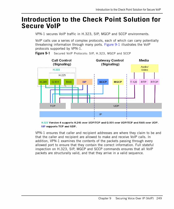
Introduction to the Check Point Solution for Secure VoIP
Chapter 9 Securing Voice Over IP (VoIP) 249
Introduction to the Check Point Solution for Secure VoIP
VPN-1 secures VoIP traffic in H.323, SIP, MGCP and SCCP environments.
VoIP calls use a series of complex protocols, each of which can carry potentially threatening information through many ports. Figure 9-1 illustrates the VoIP protocols supported by VPN-1.Figure 9-1 Secured VoIP Protocols: SIP, H.323, MGCP and SCCP
VPN-1 ensures that caller and recipient addresses are where they claim to be and that the caller and recipient are allowed to make and receive VoIP calls. In addition, VPN-1 examines the contents of the packets passing through every allowed port to ensure that they contain the correct information. Full stateful inspection on H.323, SIP, MGCP and SCCP commands ensures that all VoIP packets are structurally valid, and that they arrive in a valid sequence.
Control Signalling and Media Protocols
250
Control Signalling and Media ProtocolsA phone call on both an ordinary digital phone network and a VoIP network is made up of media and control signals. The voice conversation itself is the media stream. Dial tones and ringing tones, for example, are an indication that call control processes are taking place.
The various VoIP protocols all use very different technologies, though they have the same aims. As illustrated in Figure 9-1 on page 249, VoIP protocols handle the following call control (or gateway) control and media functions:
• Call Control (Signalling): Responsible for setting up the call, finding the peer, negotiating coding protocols, making the connection and ending the call.
• Gateway Control: Similar to call control, Gateway Control is responsible for communication between VoIP gateways, rather than between endpoint phones. These gateways act as intermediaries on behalf of the phones.
• Media: The actual voice. Both VoIP and ordinary phone networks use RTP/RTCP for the media. RTP carries the actual media and RTCP carries status and control information.
Control signals open both fixed (known) and dynamic ports. The parties of a call then use control signals to negotiate dynamically assigned ports that each side opens to receive the RTP/RTCP media stream.
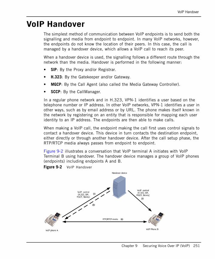
VoIP Handover
Chapter 9 Securing Voice Over IP (VoIP) 251
VoIP HandoverThe simplest method of communication between VoIP endpoints is to send both the signalling and media from endpoint to endpoint. In many VoIP networks, however, the endpoints do not know the location of their peers. In this case, the call is managed by a handover device, which allows a VoIP call to reach its peer.
When a handover device is used, the signalling follows a different route through the network than the media. Handover is performed in the following manner:
• SIP: By the Proxy and/or Registrar.
• H.323: By the Gatekeeper and/or Gateway.
• MGCP: By the Call Agent (also called the Media Gateway Controller).
• SCCP: By the CallManager.
In a regular phone network and in H.323, VPN-1 identifies a user based on the telephone number or IP address. In other VoIP networks, VPN-1 identifies a user in other ways, such as by email address or by URL. The phone makes itself known in the network by registering on an entity that is responsible for mapping each user identity to an IP address. The endpoints are then able to make calls.
When making a VoIP call, the endpoint making the call first uses control signals to contact a handover device. This device in turn contacts the destination endpoint, either directly or through another handover device. After the call setup phase, the RTP/RTCP media always passes from endpoint to endpoint.
Figure 9-2 illustrates a conversation that VoIP terminal A initiates with VoIP Terminal B using handover. The handover device manages a group of VoIP phones (endpoints) including endpoints A and B. Figure 9-2 VoIP Handover
VoIP Handover
252
The following is a typical VoIP Handover workflow:
1. Endpoint A sends control signals to the handover device.
2. The handover device and the endpoints agree on which ports to use to communicate, depending on the protocol and the topology.
3. The handover device routes the control signal to endpoint B.
4. The handover device provides A with the IP address and the destination port of B.
5. A sends the media directly to and from endpoint to endpoint.
When to Enforce HandoverAlthough enforcing handover using a VoIP domain adds security by providing access control for the VoIP signal protocols, it is not always possible to define a VoIP domain. The handover device may be maintained by an external carrier and you do not know which machines the handover device controls. Likewise, the handover device may be trusted. In these cases, it is either impossible or unnecessary to enforce the handover and there is no need to define a VoIP domain.

VoIP Application Intelligence
Chapter 9 Securing Voice Over IP (VoIP) 253
VoIP Application IntelligenceIn This Section
Introduction to VoIP Application IntelligenceVPN-1 secures VoIP networks by eliminating common threats to VoIP traffic. These threats include call hijacking, call theft, network hacking and Denial of Service (DoS) attacks (for a description of these threats, refer to “The Need to Secure Voice Over IP” on page 248).
VPN-1 provides VoIP security by inspecting the VoIP control signals that pass through the gateway. Using information derived from the control signals, VPN-1 is responsible for:
• “Restricting Handover Locations Using a VoIP Domain”
• “Controlling Signalling and Media Connections”
• “Preventing Denial of Service Attacks”
• “Protocol-Specific Application Intelligence”
Introduction to VoIP Application Intelligence page 253
Restricting Handover Locations Using a VoIP Domain page 254
Controlling Signalling and Media Connections page 255
Protocol-Specific Application Intelligence page 256

VoIP Application Intelligence
254
Restricting Handover Locations Using a VoIP Domain
Handover devices are responsible for rerouting call control signals. VPN-1 prevents the abuse of the redirection capabilities by defining a VoIP domain. The handover device can only route calls to the endpoints in its VoIP domain. The VoIP domain also controls the allowed direction of the call.
For example, in Figure 9-3, if A and B are in the VoIP domain of the handover device C, VPN-1 ensures that A sends its media streams only to B by verifying that the address of B (which in step 3 the handover device C provided to A) is in the VoIP domain. This process prevents unwanted callers from getting through the firewall.Figure 9-3 VoIP Security by VPN-1

VoIP Application Intelligence
Chapter 9 Securing Voice Over IP (VoIP) 255
Controlling Signalling and Media ConnectionsControl signals always pass through the VPN-1 gateway. VPN-1 secures the call by opening RTP/RTCP ports only for those endpoints that were negotiated during signalling. It keeps those ports open only for as long as required and then closes them as soon as the call ends (without waiting for a time-out). The order and direction of the packets is also secured.
VoIP Billing IssuesVPN-1 closes RTP/RTCP data connections due to potential security threats in VoIP billing. Security is compromised when the control and media connections follow different routes. The handover device is responsible for billing, but the RTP (the voice media) is not routed through this device. Instead, the RTP is routed between the IP Phones, which poses a security threat because IP Phones can send VoIP control messages that indicate the call has ended, but continue sending and receiving media (the RTP connection).
VPN-1 secures billing processes by monitoring the relationship between the control and media connections. VPN-1 inspects the VoIP services and deletes the media connection when the messages in the control connection specify that the media connection must end.
If both endpoints are on the same side of the VPN-1 gateway, the VPN-1 does not open any ports for the media.
Preventing Denial of Service AttacksA rogue IP phone could create Denial of Service (DoS) attacks by flooding the network with calls and interfering with the proper use of the phone network.
SmartDefense protects against DoS attacks directed against VoIP networks by limiting the number of call attempts per minute that the VPN-1 gateway allows from an individual IP address. Calls from handover devices are not counted because they make a large number of calls.

VoIP Application Intelligence
256
Protocol-Specific Application IntelligenceVPN-1 understands complex VoIP protocols and performs application layer filtering of SIP, H.323, MGCP and SCCP packets. For additional information, refer to:
• “Application Intelligence for SIP” on page 264.
• “Application Intelligence for H.323” on page 283.
• “MGCP Network Security and Application Intelligence” on page 305.
• “SCCP Network Security and Application Intelligence” on page 312

VoIP Logging
Chapter 9 Securing Voice Over IP (VoIP) 257
VoIP LoggingVPN-1 provides detailed, protocol-specific logs for VoIP traffic. If VoIP logging is disabled, then only standard logging takes place, showing the source, destination and protocol information. SIP, H.323, MGCP and SCCP events are logged in SmartView Tracker. There is also a predefined SmartView Tracker VoIP log query.
To enable VoIP logging:
• From the Global Properties Log and Alert page, select the Log VoIP connection option. The following VoIP log fields are displayed:
• Reg. IP-phones : Call registration events. For SIP and MGCP events, this field shows the URL, for example, [email protected]. For H.323 events, this field shows the phone number, for example, 123456#7.
• Source IP Phone and Destination IP Phone: Call setup events.
• Media Type: Type of media (audio, video, instant messaging, applications or unknown) flowing between the source and destination IP Phones.
• Information: Call and security information, for example, the port used, commands used and illegal direction and setup messages. For MGCP events, the commands are shown.
Protocol-Specific Security
258
Protocol-Specific SecurityThe following sections describe the specific security requirements of the VoIP protocols supported by VPN-1.
In This Section
Securing SIP-Based VoIP page 259
Securing H.323-Based VoIP page 279
Securing MGCP-Based VoIP page 303
Securing SCCP-Based VoIP page 311
Securing SIP-Based VoIP
Chapter 9 Securing Voice Over IP (VoIP) 259
Securing SIP-Based VoIP
SIP Architectural Elements in the Security Rule Base page 260
Supported SIP RFCs and Standards page 261
Secured SIP Topologies and NAT Support page 262
Application Intelligence for SIP page 264
SmartDefense Application Intelligence for SIP page 265
Synchronizing User Information page 267
SIP Services page 267
Using SIP on a Non-Default Port page 268
ClusterXL and Multicast Support for SIP page 268
Securing SIP-Based Instant Messenger Applications page 268
Configuring SIP-Based VoIP page 269
Note - Before reading this section, read “Introduction to the Check Point Solution for Secure VoIP” on page 249 to “Protocol-Specific Security” on page 258.
The SIP protocol is described in this section only to the extent required to secure SIP traffic using VPN-1.
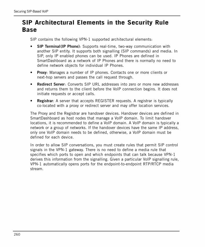
Securing SIP-Based VoIP
260
SIP Architectural Elements in the Security Rule Base
SIP contains the following VPN-1 supported architectural elements:
• SIP Terminal(IP Phone): Supports real-time, two-way communication with another SIP entity. It supports both signalling (SIP commands) and media. In SIP, only IP enabled phones can be used. IP Phones are defined in SmartDashboard as a network of IP Phones and there is normally no need to define network objects for individual IP Phones.
• Proxy: Manages a number of IP phones. Contacts one or more clients or next-hop servers and passes the call request through.
• Redirect Server : Converts SIP URL addresses into zero or more new addresses and returns them to the client before the VoIP connection begins. It does not initiate requests or accept calls.
• Registrar: A server that accepts REGISTER requests. A registrar is typically co-located with a proxy or redirect server and may offer location services.
The Proxy and the Registrar are handover devices. Handover devices are defined in SmartDashboard as host nodes that manage a VoIP domain. To limit handover locations, it is recommended to define a VoIP domain. A VoIP domain is typically a network or a group of networks. If the handover devices have the same IP address, only one VoIP domain needs to be defined, otherwise, a VoIP domain must be defined for each device.
In order to allow SIP conversations, you must create rules that permit SIP control signals in the VPN-1 gateway. There is no need to define a media rule that specifies which ports to open and which endpoints that can talk because VPN-1 derives this information from the signalling. Given a particular VoIP signalling rule, VPN-1 automatically opens ports for the endpoint-to-endpoint RTP/RTCP media stream.
Securing SIP-Based VoIP
Chapter 9 Securing Voice Over IP (VoIP) 261
Supported SIP RFCs and StandardsThe following SIP RFCs and standards are supported by VPN-1:
• RFC 3261 - The most recent SIP RFC.
• RFC 3372 - Session Initiation Protocol for Telephones (SIP-T). Refer to “Configuring SIP-T Support” on page 277 for details.
• RFC 3311 - UPDATE message.
• RFC 2976 - INFO message.
• RFC 3515 - REFER message.
• RFC 3265 - SIP Events.
• RFC 3262 - Reliability of Provisional Responses.
• RFC 3428 - MESSAGE message.
• MSN messenger over SIP.
• SIP over TCP.
• SIP over UDP.
• SIP early media.
SIP can be configured using the standard, dynamic and nonstandard ports.
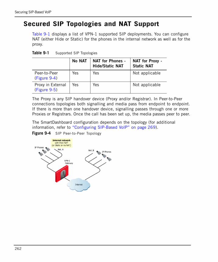
Securing SIP-Based VoIP
262
Secured SIP Topologies and NAT SupportTable 9-1 displays a list of VPN-1 supported SIP deployments. You can configure NAT (either Hide or Static) for the phones in the internal network as well as for the proxy.
The Proxy is any SIP handover device (Proxy and/or Registrar). In Peer-to-Peer connections topologies both signalling and media pass from endpoint to endpoint. If there is more than one handover device, signalling passes through one or more Proxies or Registrars. Once the call has been set up, the media passes peer to peer.
The SmartDashboard configuration depends on the topology (for additional information, refer to “Configuring SIP-Based VoIP” on page 269). Figure 9-4 SIP Peer-to-Peer Topology
Table 9-1 Supported SIP Topologies
No NAT NAT for Phones -
Hide/Static NAT
NAT for Proxy -
Static NAT
Peer-to-Peer (Figure 9-4)
Yes Yes Not applicable
Proxy in External (Figure 9-5)
Yes Yes Not applicable

Securing SIP-Based VoIP
Chapter 9 Securing Voice Over IP (VoIP) 263
Figure 9-5 SIP Proxy in Internet with NAT for Internal Phones
Additional Conditions for Using NAT in SIP NetworksSIP can be used with Network Address Translation (NAT), subject to the following conditions:
• Hide NAT can be used for all types of calls (incoming, outgoing, internal and external). However, Manual Hide NAT rules cannot be used with Hide NAT for incoming calls. For security reasons, when using Hide NAT for incoming calls, the Destination of the VoIP call in the appropriate rule in the Security Rule Base cannot be Any.
• When both endpoints are on the trusted side of the VPN-1 gateway, calls cannot be made from the same source to two endpoints, where one endpoint is NATed (either Static or Hide) and the other is not.
• Bidirectional NAT of VoIP calls is not supported.
Securing SIP-Based VoIP
264
Application Intelligence for SIP VPN-1 restricts handover locations and controls signalling and data connections (for additional information, refer to “VoIP Application Intelligence” on page 253). For SIP, VPN-1 Application Intelligence ensures that packets conform to RFC 3261 for SIP over UDP and TCP and inspects SIP-based Instant Messaging protocols. It protects against Denial of Service (DoS) attacks and penetration attempts such as connection hijacking and manipulation.
VPN-1 validates the expected usage of the SIP protocol, for example, if an end of call message is sent immediately after the start of the call, the call is denied because this behavior is characteristic of a DoS attack.
Application layer verification includes:
• Checking for binaries and illegal characters in the packets.
• Enforcing RFC header fields.
• Restricting the length of header fields.
• Removing unknown media types.
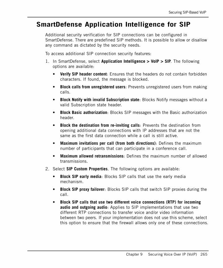
Securing SIP-Based VoIP
Chapter 9 Securing Voice Over IP (VoIP) 265
SmartDefense Application Intelligence for SIPAdditional security verification for SIP connections can be configured in SmartDefense. There are predefined SIP methods. It is possible to allow or disallow any command as dictated by the security needs.
To access additional SIP connection security features:
1. In SmartDefense, select Application Intelligence > VoIP > SIP. The following options are available:
• Verify SIP header content: Ensures that the headers do not contain forbidden characters. If found, the message is blocked.
• Block calls from unregistered users: Prevents unregistered users from making calls.
• Block Notify with invalid Subscription state: Blocks Notify messages without a valid Subscription state header.
• Block Basic authorization: Blocks SIP messages with the Basic authorization header.
• Block the destination from re-inviting calls: Prevents the destination from opening additional data connections with IP addresses that are not the same as the first data connection while a call is still active.
• Maximum invitations per call (from both directions): Defines the maximum number of participants that can participate in a conference call.
• Maximum allowed retransmissions: Defines the maximum number of allowed transmissions.
2. Select SIP Custom Properties. The following options are available:
• Block SIP early media: Blocks SIP calls that use the early media mechanism.
• Block SIP proxy failover: Blocks SIP calls that switch SIP proxies during the call.
• Block SIP calls that use two different voice connections (RTP) for incoming audio and outgoing audio: Applies to SIP implementations that use two different RTP connections to transfer voice and/or video information between two peers. If your implementation does not use this scheme, select this option to ensure that the firewall allows only one of these connections.
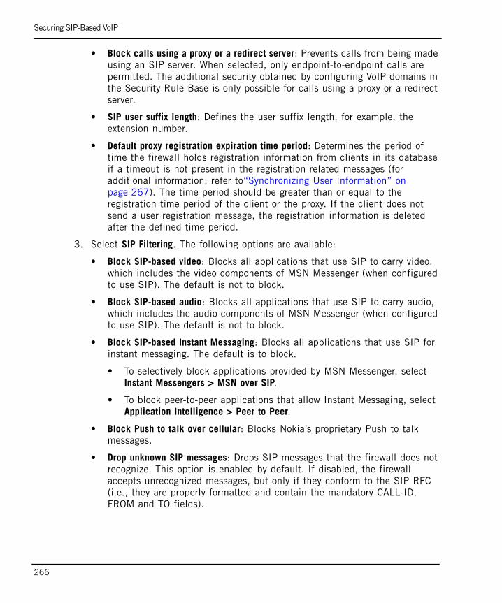
Securing SIP-Based VoIP
266
• Block calls using a proxy or a redirect server: Prevents calls from being made using an SIP server. When selected, only endpoint-to-endpoint calls are permitted. The additional security obtained by configuring VoIP domains in the Security Rule Base is only possible for calls using a proxy or a redirect server.
• SIP user suffix length: Defines the user suffix length, for example, the extension number.
• Default proxy registration expiration time period: Determines the period of time the firewall holds registration information from clients in its database if a timeout is not present in the registration related messages (for additional information, refer to“Synchronizing User Information” on page 267). The time period should be greater than or equal to the registration time period of the client or the proxy. If the client does not send a user registration message, the registration information is deleted after the defined time period.
3. Select SIP Filtering. The following options are available:
• Block SIP-based video: Blocks all applications that use SIP to carry video, which includes the video components of MSN Messenger (when configured to use SIP). The default is not to block.
• Block SIP-based audio: Blocks all applications that use SIP to carry audio, which includes the audio components of MSN Messenger (when configured to use SIP). The default is not to block.
• Block SIP-based Instant Messaging: Blocks all applications that use SIP for instant messaging. The default is to block.
• To selectively block applications provided by MSN Messenger, select Instant Messengers > MSN over SIP.
• To block peer-to-peer applications that allow Instant Messaging, select Application Intelligence > Peer to Peer.
• Block Push to talk over cellular: Blocks Nokia’s proprietary Push to talk messages.
• Drop unknown SIP messages: Drops SIP messages that the firewall does not recognize. This option is enabled by default. If disabled, the firewall accepts unrecognized messages, but only if they conform to the SIP RFC (i.e., they are properly formatted and contain the mandatory CALL-ID, FROM and TO fields).
Securing SIP-Based VoIP
Chapter 9 Securing Voice Over IP (VoIP) 267
Synchronizing User InformationThe user IP Phone sends SIP messages to the Redirect server in order to register on the network. Once a phone is registered, it can make calls.
These SIP messages cross the VPN-1 gateway, which reads them. The VoIP user databases on VPN-1 and the Redirect server are therefore always synchronized.
Registration makes it possible to initiate calls from outside the VPN-1 gateway to phones whose addresses are translated using Hide NAT.
If the VPN-1 machine is rebooted, the VoIP user database is deleted. The cpstop/cpstart commands do not delete the user database.
SIP ServicesThe following predefined SIP services are available:
• sip and sip-tcp: Used to enforce handover. Use a VoIP domain in the source or destination of the rule together with the sip service.
• sip_any and sip-tcp_any: Used if not enforcing handover. Do not place a VoIP domain in the source or destination of the rule. Instead, use Any or a network object, together with the sip_any or sip-tcp_any service. If a VoIP domain is used with the sip_any or sip-tcp_any service, it is equivalent to the sip service.
For VoIP equipment that uses SIP TCP, use the sip-tcp and sip-tcp_any services. When it uses UDP, use the sip and sip_any services.
When these services are employed, registration messages are tracked and a database is maintained that includes the details of the IP phones and the users. If an incoming call is made to a Hide NATed address, VPN-1 verifies that the user exists in the sip registration database before allowing the call, which can prevent DoS attacks.
To view a list of the online IP phones:
• Run the fw tab -t sip_registration -f command.
Note - The services sip and sip_any cannot be used in the same rule because they contradict each other. The same is true for sip-tcp and sip-tcp_any.
Securing SIP-Based VoIP
268
Using SIP on a Non-Default PortBy default, SIP uses the UDP port 5060, however, SIP phones and SIP Proxies can be configured to use a different port. VPN-1 can enforce SIP security on any SIP port. To configure a new port, a new UDP service must be defined in SmartDashboard, with SIP rules defined in the Security Rule Base. You can use both the newly defined service and the predefined services (sip and sip_any) in the same rule.
To configure a new SIP service:
1. From the SmartDashboard main menu, select Manage > Services > New… > UDP.
2. In the UDP Service Properties window, name the new service and specify the new SIP port.
3. Click Advanced….
4. In the Advanced UDP Service Properties window, select the sip_udp Protocol Type and click OK.
5. Define a rule in the Security Rule Base that uses the new service.
ClusterXL and Multicast Support for SIPSIP calls can be made across a ClusterXL gateway cluster in either High Availability or Load Sharing modes. In Load Sharing Mode, the Sticky Decision Function must be enabled (for additional information, refer to the ClusterXL Administration Guide).
The fw_sip_allow_mcast (true, false) property allows or drops multicast RTP traffic. The default value of this property is false. This is a per module property. To change the value, run the fw ctl set int fw_sip_allow_mcast command.
Securing SIP-Based Instant Messenger Applications
For information on Securing SIP-Based Instant Messenger Applications and MSN Messenger over SIP, refer to “Securing Instant Messaging Applications” on page 319.
Securing SIP-Based VoIP
Chapter 9 Securing Voice Over IP (VoIP) 269
Configuring SIP-Based VoIP
In This Section
SIP Rules for a Peer-to-Peer No-Proxy Topology page 270
SIP Rules for a Proxy in an External Network page 271
SIP Rules for a Proxy-to-Proxy Topology page 273
SIP Rules for a Proxy in DMZ Topology page 275
Configuring SIP-Based Instant Messenger Applications page 277
Configuring SIP-T Support page 277
Note - Security rules can be defined that allow either bidirectional calls or only incoming or outgoing calls. The examples provided in the following sections describe how to define bidirectional rules.

Securing SIP-Based VoIP
270
SIP Rules for a Peer-to-Peer No-Proxy TopologyFigure 9-6 illustrates SIP rules for a peer-to-peer topology.Figure 9-6 SIP Peer-to-Peer Topology
To configure SIP rules for a peer-to-peer topology:
1. Define a rule that allows IP phones in Net_A to call Net_Band, and vice versa (Table 9-2)
2. Define Hide NAT (or Static NAT) for the phones in the internal network by editing the network object for Net_A.
3. In the NAT tab, select Add Automatic Address Translation Rules and then the Translation method (Hide or Static).
4. Select Application Intelligence > VoIP > SIP to configure SmartDefense options (for additional information, refer to “SmartDefense Application Intelligence for SIP” on page 265 or the online help).
5. Install the security policy.
Table 9-2
Source Destination Service Action Comment
Net_ANet_B
Net_BNet_A
sip or sip-tcp
Accept Bidirectional calls
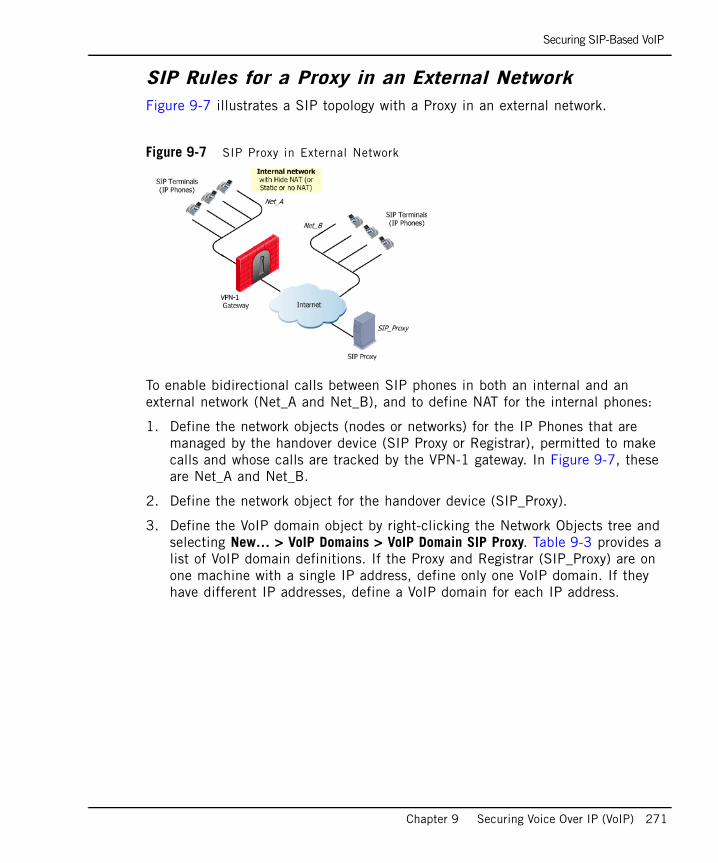
Securing SIP-Based VoIP
Chapter 9 Securing Voice Over IP (VoIP) 271
SIP Rules for a Proxy in an External NetworkFigure 9-7 illustrates a SIP topology with a Proxy in an external network.
Figure 9-7 SIP Proxy in External Network
To enable bidirectional calls between SIP phones in both an internal and an external network (Net_A and Net_B), and to define NAT for the internal phones:
1. Define the network objects (nodes or networks) for the IP Phones that are managed by the handover device (SIP Proxy or Registrar), permitted to make calls and whose calls are tracked by the VPN-1 gateway. In Figure 9-7, these are Net_A and Net_B.
2. Define the network object for the handover device (SIP_Proxy).
3. Define the VoIP domain object by right-clicking the Network Objects tree and selecting New… > VoIP Domains > VoIP Domain SIP Proxy. Table 9-3 provides a list of VoIP domain definitions. If the Proxy and Registrar (SIP_Proxy) are on one machine with a single IP address, define only one VoIP domain. If they have different IP addresses, define a VoIP domain for each IP address.
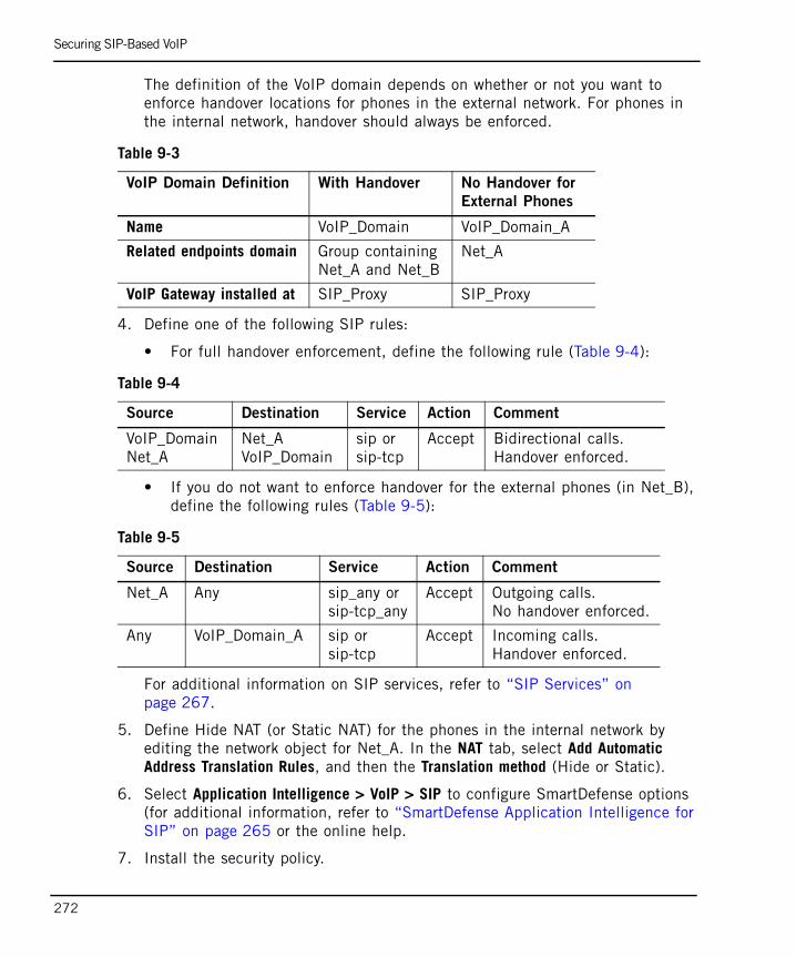
Securing SIP-Based VoIP
272
The definition of the VoIP domain depends on whether or not you want to enforce handover locations for phones in the external network. For phones in the internal network, handover should always be enforced.
4. Define one of the following SIP rules:
• For full handover enforcement, define the following rule (Table 9-4):
• If you do not want to enforce handover for the external phones (in Net_B), define the following rules (Table 9-5):
For additional information on SIP services, refer to “SIP Services” on page 267.
5. Define Hide NAT (or Static NAT) for the phones in the internal network by editing the network object for Net_A. In the NAT tab, select Add Automatic Address Translation Rules, and then the Translation method (Hide or Static).
6. Select Application Intelligence > VoIP > SIP to configure SmartDefense options (for additional information, refer to “SmartDefense Application Intelligence for SIP” on page 265 or the online help.
7. Install the security policy.
Table 9-3
VoIP Domain Definition With Handover No Handover for
External Phones
Name VoIP_Domain VoIP_Domain_A
Related endpoints domain Group containingNet_A and Net_B
Net_A
VoIP Gateway installed at SIP_Proxy SIP_Proxy
Table 9-4
Source Destination Service Action Comment
VoIP_Domain Net_A
Net_A VoIP_Domain
sip or sip-tcp
Accept Bidirectional calls. Handover enforced.
Table 9-5
Source Destination Service Action Comment
Net_A Any sip_any orsip-tcp_any
Accept Outgoing calls. No handover enforced.
Any VoIP_Domain_A sip or sip-tcp
Accept Incoming calls. Handover enforced.
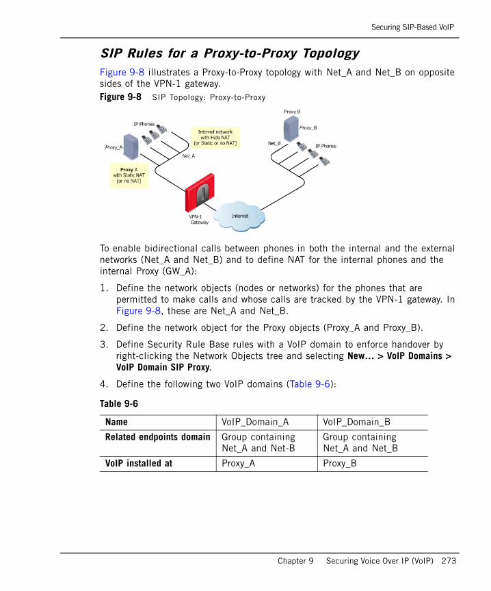
Securing SIP-Based VoIP
Chapter 9 Securing Voice Over IP (VoIP) 273
SIP Rules for a Proxy-to-Proxy TopologyFigure 9-8 illustrates a Proxy-to-Proxy topology with Net_A and Net_B on opposite sides of the VPN-1 gateway. Figure 9-8 SIP Topology: Proxy-to-Proxy
To enable bidirectional calls between phones in both the internal and the external networks (Net_A and Net_B) and to define NAT for the internal phones and the internal Proxy (GW_A):
1. Define the network objects (nodes or networks) for the phones that are permitted to make calls and whose calls are tracked by the VPN-1 gateway. In Figure 9-8, these are Net_A and Net_B.
2. Define the network object for the Proxy objects (Proxy_A and Proxy_B).
3. Define Security Rule Base rules with a VoIP domain to enforce handover by right-clicking the Network Objects tree and selecting New… > VoIP Domains > VoIP Domain SIP Proxy.
4. Define the following two VoIP domains (Table 9-6):
Table 9-6
Name VoIP_Domain_A VoIP_Domain_B
Related endpoints domain Group containingNet_A and Net-B
Group containingNet_A and Net_B
VoIP installed at Proxy_A Proxy_B
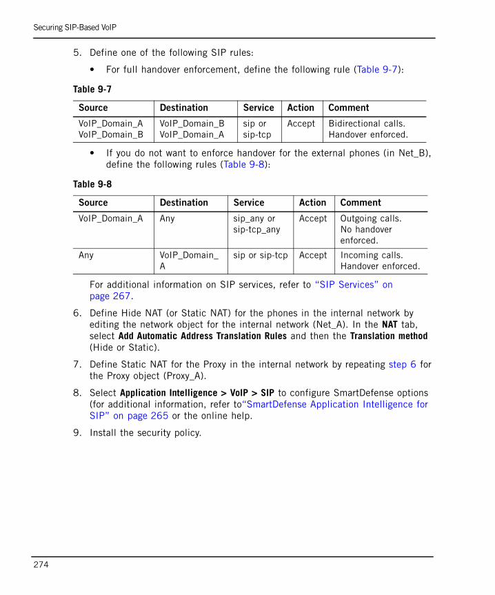
Securing SIP-Based VoIP
274
5. Define one of the following SIP rules:
• For full handover enforcement, define the following rule (Table 9-7):
• If you do not want to enforce handover for the external phones (in Net_B), define the following rules (Table 9-8):
For additional information on SIP services, refer to “SIP Services” on page 267.
6. Define Hide NAT (or Static NAT) for the phones in the internal network by editing the network object for the internal network (Net_A). In the NAT tab, select Add Automatic Address Translation Rules and then the Translation method (Hide or Static).
7. Define Static NAT for the Proxy in the internal network by repeating step 6 for the Proxy object (Proxy_A).
8. Select Application Intelligence > VoIP > SIP to configure SmartDefense options (for additional information, refer to“SmartDefense Application Intelligence for SIP” on page 265 or the online help.
9. Install the security policy.
Table 9-7
Source Destination Service Action Comment
VoIP_Domain_AVoIP_Domain_B
VoIP_Domain_BVoIP_Domain_A
sip or sip-tcp
Accept Bidirectional calls.Handover enforced.
Table 9-8
Source Destination Service Action Comment
VoIP_Domain_A Any sip_any orsip-tcp_any
Accept Outgoing calls. No handover enforced.
Any VoIP_Domain_A
sip or sip-tcp Accept Incoming calls. Handover enforced.
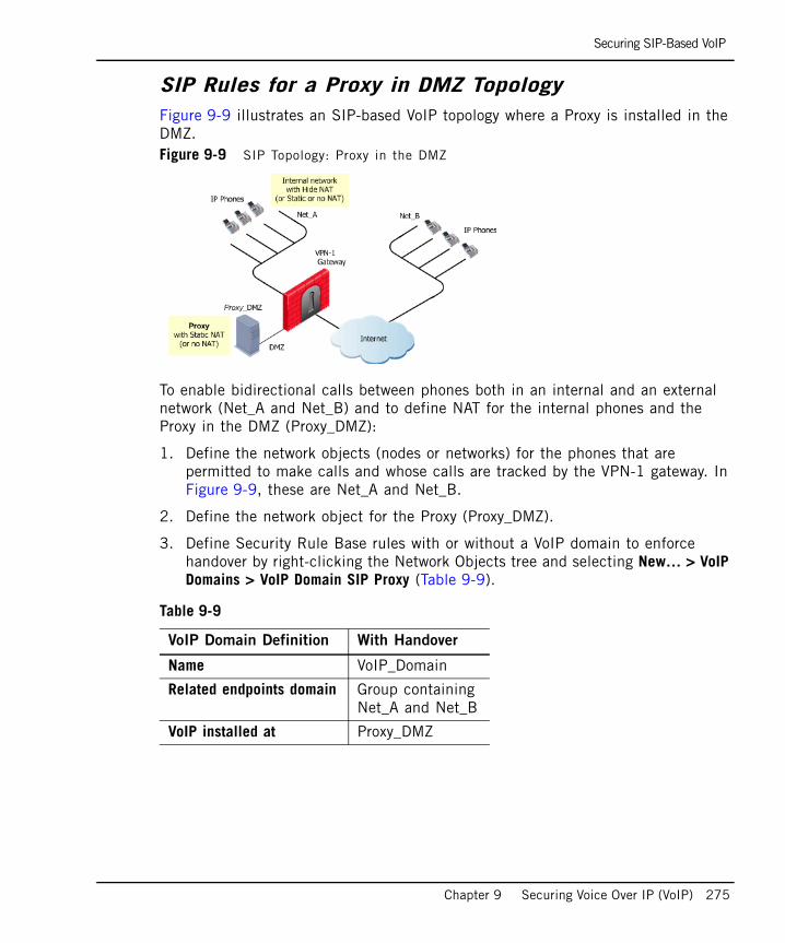
Securing SIP-Based VoIP
Chapter 9 Securing Voice Over IP (VoIP) 275
SIP Rules for a Proxy in DMZ TopologyFigure 9-9 illustrates an SIP-based VoIP topology where a Proxy is installed in the DMZ. Figure 9-9 SIP Topology: Proxy in the DMZ
To enable bidirectional calls between phones both in an internal and an external network (Net_A and Net_B) and to define NAT for the internal phones and the Proxy in the DMZ (Proxy_DMZ):
1. Define the network objects (nodes or networks) for the phones that are permitted to make calls and whose calls are tracked by the VPN-1 gateway. In Figure 9-9, these are Net_A and Net_B.
2. Define the network object for the Proxy (Proxy_DMZ).
3. Define Security Rule Base rules with or without a VoIP domain to enforce handover by right-clicking the Network Objects tree and selecting New… > VoIP Domains > VoIP Domain SIP Proxy (Table 9-9).
Table 9-9
VoIP Domain Definition With Handover
Name VoIP_Domain
Related endpoints domain Group containingNet_A and Net_B
VoIP installed at Proxy_DMZ
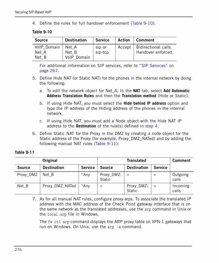
Securing SIP-Based VoIP
276
4. Define the rules for full handover enforcement (Table 9-10).
For additional information on SIP services, refer to “SIP Services” on page 267.
5. Define Hide NAT (or Static NAT) for the phones in the internal network by doing the following:
a. To edit the network object for Net_A, In the NAT tab, select Add Automatic Address Translation Rules and then the Translation method (Hide or Static).
b. If using Hide NAT, you must select the Hide behind IP address option and type the IP address of the Hiding address of the phones in the internal network.
c. If using Hide NAT, you must add a Node object with the Hide NAT IP address to the Destination of the rule(s) defined in step 4.
6. Define Static NAT for the Proxy in the DMZ by creating a node object for the Static address of the Proxy (for example, Proxy_DMZ_NATed) and by adding the following manual NAT rules (Table 9-11):
7. As for all manual NAT rules, configure proxy-arps. To associate the translated IP address with the MAC address of the Check Point gateway interface that is on the same network as the translated addresses, use the arp command in Unix or the local.arp file in Windows.
The fw ctl arp command displays the ARP proxy table on VPN-1 gateways that run on Windows. On Unix, use the arp -a command.
Table 9-10
Source Destination Service Action Comment
VoIP_DomainNet_ANet_B
Net_ANet_BVoIP_Domain
sip or sip-tcp
Accept Bidirectional calls. Handover enforced.
Table 9-11
Original Translated Comment
Source Destination Service Source Destination Service
Proxy_DMZ Net_B *Any Proxy_DMZ:Static
= = Outgoingcalls
Net_B Proxy_DMZ_NATed *Any = Proxy_DMZ:Static
= Incomingcalls

Securing SIP-Based VoIP
Chapter 9 Securing Voice Over IP (VoIP) 277
8. Select Application Intelligence > VoIP > SIP to configure SmartDefense options (for additional information, refer to “SmartDefense Application Intelligence for SIP” on page 265 or the online help.
9. Install the security policy.
Configuring SIP-Based Instant Messenger ApplicationsFor information on configuring MSN Messenger over SIP, refer to “Configuring SIP-based Instant Messengers” on page 325.
Configuring SIP-T SupportTo configure support for RFC 3372 Session Initiation Protocol for Telephones (SIP-T):
1. Add the $FWDIR/lib/user.def line on the SmartCenter server:
where first_ip and second_ip are the IP addresses between which (bi-directional) SIP-T are allowed. For example, to allow SIP-T between 192.1.1.1 and 192.1.1.2, and between 192.1.1.1 and 192.1.1.3 add the following line:
If the file does not exist, create it.
2. Save the file.
3. Install the security policy.
sipt_hosts = { < first_ip, second_ip> , < first_ip, second_ip> , .... ....,< first_ip, second_ip> } ;
sipt_hosts = { < 192.1.1.1, 192.1.1.2> , < 192.1.1.1, 192.1.1.3> } ;
Troubleshooting SIP
278
Troubleshooting SIPTo view a list of all of the online IP phones that VPN-1 has recorded as having registered:
Run the fw tab -t sip_registration -f command. The output of this command is a list in the username; IP address format.
To obtain information on current SIP calls:
Run the fw tab -t sip_state -f command. The following output is displayed:
• Control connection (source, destination).
• RTP connection (endpoint IP addresses).
• Call state (established, ended, registration).
• Media type (audio, video, audio/video, application).
• Number of reinvites (number of participants in a conference call).

Securing H.323-Based VoIP
Chapter 9 Securing Voice Over IP (VoIP) 279
Securing H.323-Based VoIPIn This Section
H.323 Architectural Elements in the Security Rule Base
VPN-1 supports the following H.323 architectural elements:
• IP phones, which are IP devices that handle both signalling (that is, the H.323 commands themselves) and media. They connect to an H.323 gatekeeper.
IP Phones are defined in SmartDashboard, usually as a network of IP Phones. There is normally no need to define network objects for individual IP Phones.
• Conventional telephones connect to an H.323 gateway. These are not IP devices and there is no need to define them in SmartDashboard.
• A Gatekeeper manages a collection of H.323 devices such as phones. It converts phone numbers to IP addresses. A Gatekeeper usually provide gateway services as well.
• A Gateway provides interoperability between different networks. It translates between the telephony protocol and IP.
H.323 Architectural Elements in the Security Rule Base page 279
Supported H.323 RFCs and Standards page 280
Secured H.323 Topologies and NAT Support page 280
Application Intelligence for H.323 page 283
SmartDefense Application Intelligence Settings for H.323 page 284
Gatekeeper and Gateway Call Routing page 284
H.323 Services page 286
Configuring H.323-Based VoIP page 287
Note - Before reading this section, read “Introduction to the Check Point Solution for Secure VoIP” on page 249 to “Protocol-Specific Security” on page 258.
The H.323 protocol is described in this section only to the extent required to secure H.323 traffic using VPN-1.
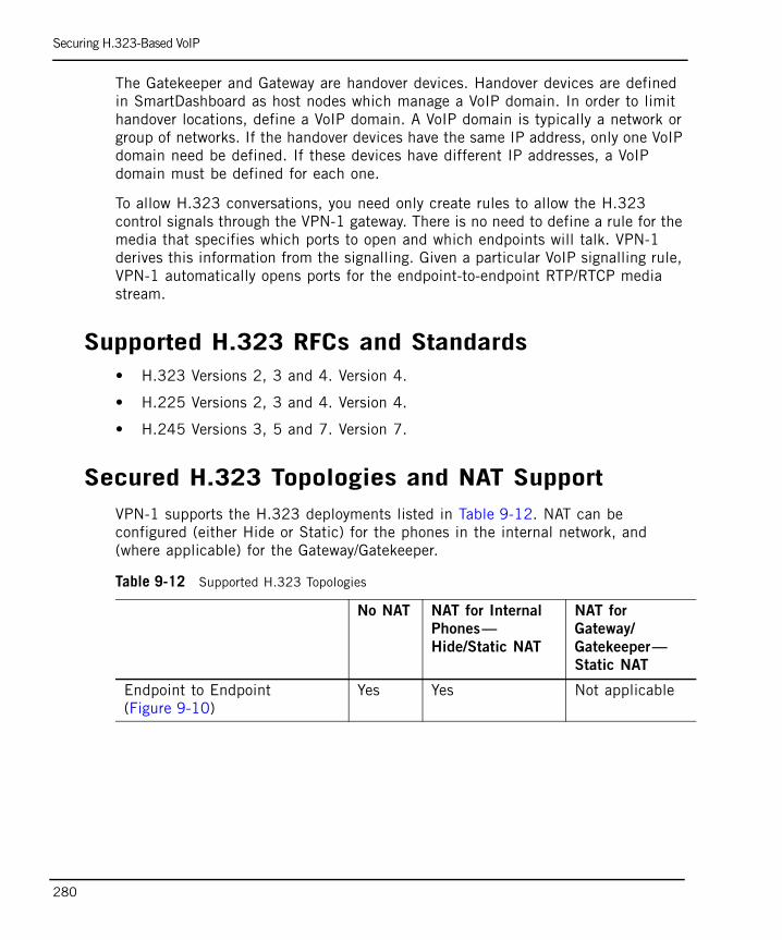
Securing H.323-Based VoIP
280
The Gatekeeper and Gateway are handover devices. Handover devices are defined in SmartDashboard as host nodes which manage a VoIP domain. In order to limit handover locations, define a VoIP domain. A VoIP domain is typically a network or group of networks. If the handover devices have the same IP address, only one VoIP domain need be defined. If these devices have different IP addresses, a VoIP domain must be defined for each one.
To allow H.323 conversations, you need only create rules to allow the H.323 control signals through the VPN-1 gateway. There is no need to define a rule for the media that specifies which ports to open and which endpoints will talk. VPN-1 derives this information from the signalling. Given a particular VoIP signalling rule, VPN-1 automatically opens ports for the endpoint-to-endpoint RTP/RTCP media stream.
Supported H.323 RFCs and Standards• H.323 Versions 2, 3 and 4. Version 4.
• H.225 Versions 2, 3 and 4. Version 4.
• H.245 Versions 3, 5 and 7. Version 7.
Secured H.323 Topologies and NAT SupportVPN-1 supports the H.323 deployments listed in Table 9-12. NAT can be configured (either Hide or Static) for the phones in the internal network, and (where applicable) for the Gateway/Gatekeeper.
Table 9-12 Supported H.323 Topologies
No NAT NAT for Internal
Phones—
Hide/Static NAT
NAT for
Gateway/
Gatekeeper—
Static NAT
Endpoint to Endpoint (Figure 9-10)
Yes Yes Not applicable
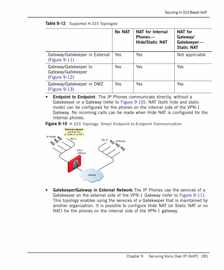
Securing H.323-Based VoIP
Chapter 9 Securing Voice Over IP (VoIP) 281
• Endpoint to Endpoint: The IP Phones communicate directly, without a Gatekeeper or a Gateway (refer to Figure 9-10). NAT (both hide and static mode) can be configured for the phones on the internal side of the VPN-1 Gateway. No incoming calls can be made when Hide NAT is configured for the internal phones.
Figure 9-10 H.323 Topology: Direct Endpoint-to-Endpoint Communication
• Gatekeeper/Gateway in External Network:The IP Phones use the services of a Gatekeeper on the external side of the VPN-1 Gateway (refer to Figure 9-11). This topology enables using the services of a Gatekeeper that is maintained by another organization. It is possible to configure Hide NAT (or Static NAT or no NAT) for the phones on the internal side of the VPN-1 gateway.
Gateway/Gatekeeper in External(Figure 9-11)
Yes Yes Not applicable
Gateway/Gatekeeper to Gateway/Gatekeeper(Figure 9-12)
Yes Yes Yes
Gateway/Gatekeeper in DMZ(Figure 9-13)
Yes Yes Yes
Table 9-12 Supported H.323 Topologies
No NAT NAT for Internal
Phones—
Hide/Static NAT
NAT for
Gateway/
Gatekeeper—
Static NAT
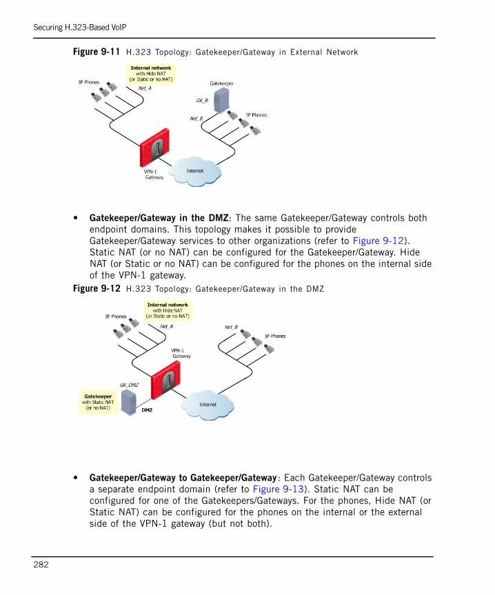
Securing H.323-Based VoIP
282
Figure 9-11 H.323 Topology: Gatekeeper/Gateway in External Network
• Gatekeeper/Gateway in the DMZ: The same Gatekeeper/Gateway controls both endpoint domains. This topology makes it possible to provide Gatekeeper/Gateway services to other organizations (refer to Figure 9-12). Static NAT (or no NAT) can be configured for the Gatekeeper/Gateway. Hide NAT (or Static or no NAT) can be configured for the phones on the internal side of the VPN-1 gateway.
Figure 9-12 H.323 Topology: Gatekeeper/Gateway in the DMZ
• Gatekeeper/Gateway to Gatekeeper/Gateway : Each Gatekeeper/Gateway controls a separate endpoint domain (refer to Figure 9-13). Static NAT can be configured for one of the Gatekeepers/Gateways. For the phones, Hide NAT (or Static NAT) can be configured for the phones on the internal or the external side of the VPN-1 gateway (but not both).

Securing H.323-Based VoIP
Chapter 9 Securing Voice Over IP (VoIP) 283
Figure 9-13 H.323 Topology: Gatekeeper/Gateway to Gatekeeper/Gateway
Application Intelligence for H.323VPN-1 supports H.323 version 4 and below, which includes H.225 version 4 and H.245 version 7. It performs the following application layer checks:
• Strict enforcement of the protocol, including the order and direction of H.323 packets.
• If the phone number sent is longer than 24 characters, the packet is dropped. This prevents buffer overruns in the server.
• Dynamic ports are only opened if the port is not used by another service. For example: If the Connect message sends port 80 for the H.245, it will not be opened. This prevents illegal use of well-known ports.
VPN-1 supports Fast Connect, an advanced H.323 capability that ensures that audio is available as soon as the phone is answered. This feature is active by default, and is always available.
Securing H.323-Based VoIP
284
SmartDefense Application Intelligence Settings for H.323
The following additional Application Intelligence checks can be configured via SmartDefense Application Intelligence > VoIP > H.323:
• Block connections re-direction: Prevents conversations being handed over on both sides. It must be unchecked in order to use Gatekeepers or Gateways.
• Prevent blank source phone numbers for gatekeeper connections: Rejects RAS connections in which the source phone number is blank. By default, they are prevented. If a field that should be present in the packet is missing, the packet is dropped.
• Disable dynamic T.120: Blocks application-sharing file transfer, used for white board, chat, and application sharing in applications such as Microsoft NetMeeting. T.120 is not allowed by default.
• Block H.245 Tunneling: Prevents the encapsulation a H.245 message in any Q.931 message. H.245 tunneling conserves resources, synchronizes call signaling and control, and reduces call setup time. H.245 Tunneling should be allowed, if the VoIP equipment supports it.
• Disable dynamic opening of H.323 connections opened from RAS messages: Controls the way the H323_ras service works. If the service is allowed in the Rule Base, this setting controls whether control connections required by all H.323 sessions will be dynamically opened by the firewall. If H.323 connections opened from RAS messages are blocked, it is necessary to allow the H323 service in the Rule Base. This setting applies only to connections that start with RAS (that is allowed and inspected by the H323_ras service).
• Drop H.323 calls that do not start with a SETUP message: Ensures that if this option is selected, all H.323/Q.931 connections that do not start with a SETUP message are dropped.
• T120 timeout: Determines how long a dynamically opened T120 connection can be idle. After this time, the connection is deleted. The default timeout is 3600 seconds.
Gatekeeper and Gateway Call RoutingH.323 routing modes define which control protocols are allowed to pass between the Gatekeepers or Gateways, and which are allowed to pass directly between the endpoints. VPN-1 can be configured to allow one or more routing modes. To understand routing modes, a basic understanding of H.323 protocols and the sequence in which they are used is required.
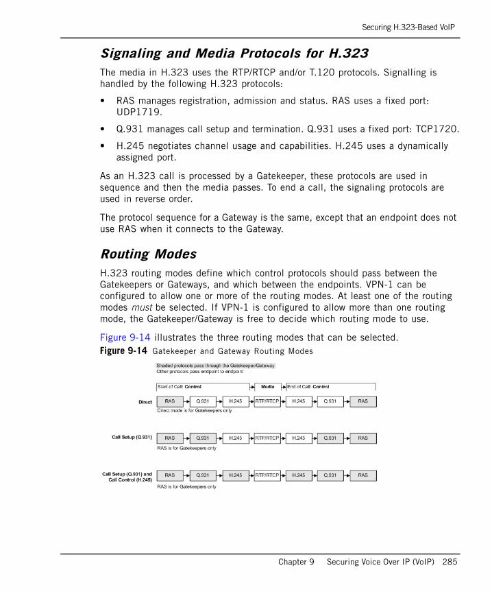
Securing H.323-Based VoIP
Chapter 9 Securing Voice Over IP (VoIP) 285
Signaling and Media Protocols for H.323The media in H.323 uses the RTP/RTCP and/or T.120 protocols. Signalling is handled by the following H.323 protocols:
• RAS manages registration, admission and status. RAS uses a fixed port: UDP1719.
• Q.931 manages call setup and termination. Q.931 uses a fixed port: TCP1720.
• H.245 negotiates channel usage and capabilities. H.245 uses a dynamically assigned port.
As an H.323 call is processed by a Gatekeeper, these protocols are used in sequence and then the media passes. To end a call, the signaling protocols are used in reverse order.
The protocol sequence for a Gateway is the same, except that an endpoint does not use RAS when it connects to the Gateway.
Routing ModesH.323 routing modes define which control protocols should pass between the Gatekeepers or Gateways, and which between the endpoints. VPN-1 can be configured to allow one or more of the routing modes. At least one of the routing modes must be selected. If VPN-1 is configured to allow more than one routing mode, the Gatekeeper/Gateway is free to decide which routing mode to use.
Figure 9-14 illustrates the three routing modes that can be selected.Figure 9-14 Gatekeeper and Gateway Routing Modes
Securing H.323-Based VoIP
286
The following routing modes are illustrated in Figure 9-14:
• Direct mode is for Gatekeepers only, and not for Gateways. Only the RAS signals pass through the Gatekeeper. All other signalling (Q.931 and H.245), as well as the RTP/RTCP media, passes directly endpoint to endpoint.
• Call Setup (Q.931) mode allows RAS (used only by Gatekeepers) and Q.931 to pass through the Gatekeeper/Gateway. H.245 and the RTP/RTCP media pass endpoint to endpoint.
• Call Setup (Q.931) and Call Control (H.245) mode allows RAS (for a Gatekeeper only), Q.931 and H.245 to pass through the Gatekeeper/Gateway. Only the RTP/RTCP media passes endpoint to endpoint.
H.323 ServicesThe following predefined services are available for use in H.323 rules. They can be used to limit the protocols that are permitted during each stage of the H.323 call. Separate rules can be defined for the different protocols:
• H323_ras_only allows only RAS. Cannot be used to make calls. If this service is used, no Application Intelligence checks (payload inspection or modification) are made. Do not use in the same rule as the H323_ras service.
• H323_ras allows a RAS port to be opened, followed by a Q.931 port. Q.931 then opens a H.245 port if needed, which in turn opens ports for RTP/RTCP or T.120. Use this service to do NAT on RAS messages. Do not use in the same rule as the H323_ras_only service.
• H323 allows a Q.931 to be opened (and if needed, a H.245 port,) which in turn opens ports for RTP/RTCP or T.120. Do not use in the same rule as the H323_any service.
• H323_any is like the H323 service, but also allows the Destination in the rule to be ANY rather than a network object. Only use H323_any if you do not know the VoIP topology, and are not enforcing handover using a VoIP domain. Do not use in the same rule as the H323 service.
Note - The services H323 and H323_any cannot be used in the same rule because they contradict each other. Similarly, the services H323_ras and H323_ras_any cannot be used in the same rule.
Securing H.323-Based VoIP
Chapter 9 Securing Voice Over IP (VoIP) 287
Configuring H.323-Based VoIP
In This Section
Choosing the Type of H.323-VoIP DomainConfigure a VoIP domain for H.323 phones if they use the Gateway or Gatekeeper to make calls. Select either a Gateway or Gatekeeper object according to the following criteria:
• Use a VoIP Domain H.323 Gateway if the first packet that the device sees when a call is initiated is a Q.931/H.225 packet, and not an RAS packet.
• Use a VoIP Domain H.323 Gatekeeper if the first packet that the device sees when a call is initiated is an RAS/H.225 packet.
For an H.323 Gatekeeper, the VoIP domain corresponds to the zone of that Gatekeeper. A zone is a collection of terminals that are managed by a single Gatekeeper. A zone has one and only one Gatekeeper.
If the Gatekeeper and Gateway have different IP addresses, define a VoIP domain for each one. If the Gateway and Gatekeeper are on single machine, and have the same IP address, define only a single VoIP Domain H.323 Gatekeeper object.
H.323 Rule for an Endpoint-to-Endpoint TopologyAn endpoint-to-endpoint topology is shown in Figure 9-15, with Net_A and Net_B on opposite sides of the VPN-1 gateway. The following procedure explains how to allow bidirectional calls between the phones in the internal network (Net_A) and phones in an external network (Net_B), and how to define NAT for the internal phones. No incoming calls can be made when Hide NAT is configured for the internal phones.
Choosing the Type of H.323-VoIP Domain page 287
H.323 Rule for an Endpoint-to-Endpoint Topology page 287
H.323 Rules for a Gatekeeper-to-Gatekeeper Topology page 288
H.323 Rules for a Gateway-to-Gateway Topology page 291
H.323 Rules for a Gatekeeper in the External Network page 292
H.323 Rules for a Gateway in the External Network page 295
H.323 Rules for a Gatekeeper in DMZ Topology page 296
H.323 Rules for a Gateway in DMZ Topology page 300
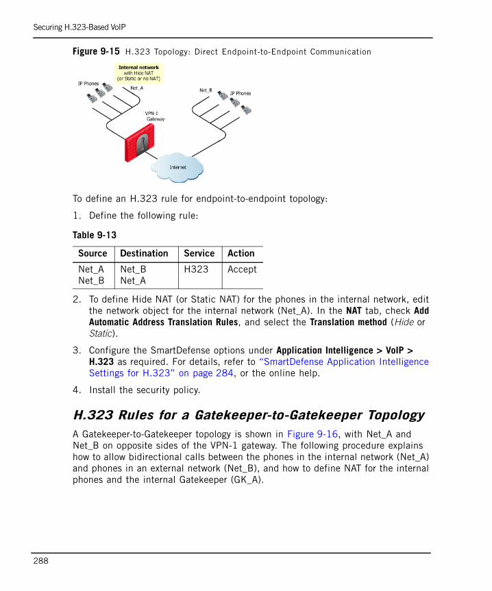
Securing H.323-Based VoIP
288
Figure 9-15 H.323 Topology: Direct Endpoint-to-Endpoint Communication
To define an H.323 rule for endpoint-to-endpoint topology:
1. Define the following rule:
2. To define Hide NAT (or Static NAT) for the phones in the internal network, edit the network object for the internal network (Net_A). In the NAT tab, check Add Automatic Address Translation Rules, and select the Translation method (Hide or Static).
3. Configure the SmartDefense options under Application Intelligence > VoIP > H.323 as required. For details, refer to “SmartDefense Application Intelligence Settings for H.323” on page 284, or the online help.
4. Install the security policy.
H.323 Rules for a Gatekeeper-to-Gatekeeper TopologyA Gatekeeper-to-Gatekeeper topology is shown in Figure 9-16, with Net_A and Net_B on opposite sides of the VPN-1 gateway. The following procedure explains how to allow bidirectional calls between the phones in the internal network (Net_A) and phones in an external network (Net_B), and how to define NAT for the internal phones and the internal Gatekeeper (GK_A).
Table 9-13
Source Destination Service Action
Net_ANet_B
Net_BNet_A
H323 Accept
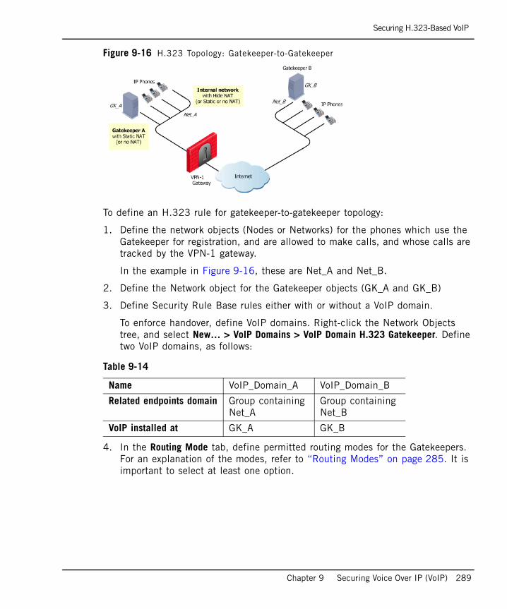
Securing H.323-Based VoIP
Chapter 9 Securing Voice Over IP (VoIP) 289
Figure 9-16 H.323 Topology: Gatekeeper-to-Gatekeeper
To define an H.323 rule for gatekeeper-to-gatekeeper topology:
1. Define the network objects (Nodes or Networks) for the phones which use the Gatekeeper for registration, and are allowed to make calls, and whose calls are tracked by the VPN-1 gateway.
In the example in Figure 9-16, these are Net_A and Net_B.
2. Define the Network object for the Gatekeeper objects (GK_A and GK_B)
3. Define Security Rule Base rules either with or without a VoIP domain.
To enforce handover, define VoIP domains. Right-click the Network Objects tree, and select New… > VoIP Domains > VoIP Domain H.323 Gatekeeper. Define two VoIP domains, as follows:
4. In the Routing Mode tab, define permitted routing modes for the Gatekeepers. For an explanation of the modes, refer to “Routing Modes” on page 285. It is important to select at least one option.
Table 9-14
Name VoIP_Domain_A VoIP_Domain_B
Related endpoints domain Group containingNet_A
Group containingNet_B
VoIP installed at GK_A GK_B
Securing H.323-Based VoIP
290
5. Now define the rules. To enforce handover, define the following rule with VoIP domains:
If you do not want to enforce handover, define the following rules:
When rules without a VoIP domain are defined, all connections other than H323_ras must be peer to peer.
For an explanation of the H.323 services, refer to “H.323 Services” on page 286.
6. To define Hide NAT (or Static NAT) for the phones in the internal network, edit the network object for the internal network (Net_A). In the NAT tab, select Add Automatic Address Translation Rules, and select the Translation method (Hide or Static).
7. To define Static NAT for the Gatekeeper/Gateway in the internal network, repeat step 6 for the Gatekeeper object (GK_A).
8. It is recommended to make the time-out of the H323_ras service equal to or greater than the Gatekeeper registration time-out. Configure the time-outs in the Advanced Properties window of the Service object.
9. Configure the SmartDefense options under Application Intelligence > VoIP > H.323 as required. For details, refer to “SmartDefense Application Intelligence Settings for H.323” on page 284, or the online help.
10. Install the security policy.
Table 9-15
Source Destination Service Action Comment
VoIP_Domain_AVoIP_Domain_B
VoIP_Domain_BVoIP_Domain_A
H323_ras Accept Bidirectional calls.Handover enforced.
Table 9-16
Source Destination Service Action Comment
GK_A GK_B H323_ras_only Accept No handover.
Net_ANet_B
Net_ANet_B
H323 Accept No handover.
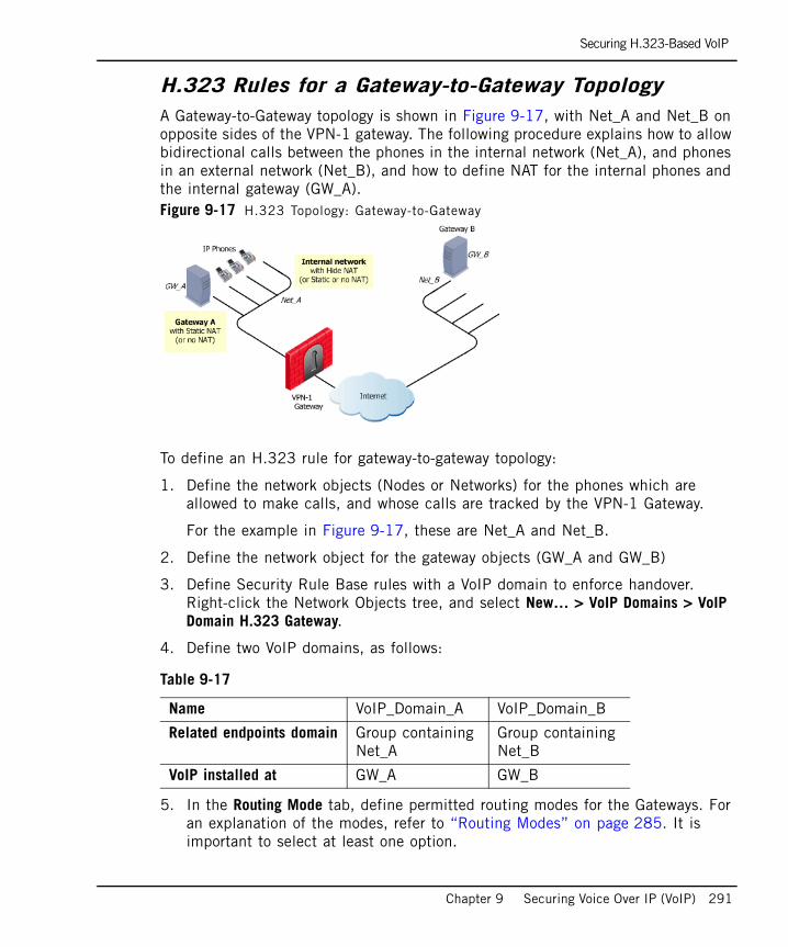
Securing H.323-Based VoIP
Chapter 9 Securing Voice Over IP (VoIP) 291
H.323 Rules for a Gateway-to-Gateway TopologyA Gateway-to-Gateway topology is shown in Figure 9-17, with Net_A and Net_B on opposite sides of the VPN-1 gateway. The following procedure explains how to allow bidirectional calls between the phones in the internal network (Net_A), and phones in an external network (Net_B), and how to define NAT for the internal phones and the internal gateway (GW_A). Figure 9-17 H.323 Topology: Gateway-to-Gateway
To define an H.323 rule for gateway-to-gateway topology:
1. Define the network objects (Nodes or Networks) for the phones which are allowed to make calls, and whose calls are tracked by the VPN-1 Gateway.
For the example in Figure 9-17, these are Net_A and Net_B.
2. Define the network object for the gateway objects (GW_A and GW_B)
3. Define Security Rule Base rules with a VoIP domain to enforce handover. Right-click the Network Objects tree, and select New… > VoIP Domains > VoIP Domain H.323 Gateway.
4. Define two VoIP domains, as follows:
5. In the Routing Mode tab, define permitted routing modes for the Gateways. For an explanation of the modes, refer to “Routing Modes” on page 285. It is important to select at least one option.
Table 9-17
Name VoIP_Domain_A VoIP_Domain_B
Related endpoints domain Group containingNet_A
Group containingNet_B
VoIP installed at GW_A GW_B
Securing H.323-Based VoIP
292
6. Now define the rules. To enforce handover, define the following rule with VoIP domains:
For an explanation of the H.323 services, refer to “H.323 Services” on page 286.
7. To define Hide NAT (or Static NAT) for the phones in the internal network, edit the network object for the internal network (Net_A). In the NAT tab, select Add Automatic Address Translation Rules, and select the Translation method (Hide or Static)
8. To define Static NAT for the Gatekeeper/Gateway in the internal network, repeat step 6 for the Gatekeeper/Gateway object (GK_A).
9. Configure the SmartDefense options under Application Intelligence > VoIP > H.323 as required. For details, refer to “SmartDefense Application Intelligence Settings for H.323” on page 284, or the online help.
10. Install the security policy.
H.323 Rules for a Gatekeeper in the External NetworkAn H.323 topology with a Gatekeeper in the Internet is shown in Figure 9-18, with Net_A and Net_B on opposite sides of the VPN-1 gateway. The following procedure explains how to allow bidirectional calls between the phones in the internal network (Net_A) and phones in an external network (Net_B), and how to define NAT for the internal phones.
Table 9-18
Source Destination Service Action Comment
VoIP_Domain_AVoIP_Domain_B
VoIP_Domain_BVoIP_Domain_A
H323 Accept Bidirectional calls.Handover enforced.
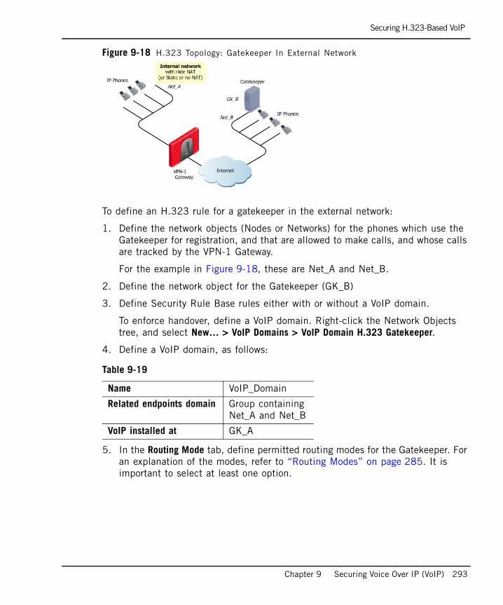
Securing H.323-Based VoIP
Chapter 9 Securing Voice Over IP (VoIP) 293
Figure 9-18 H.323 Topology: Gatekeeper In External Network
To define an H.323 rule for a gatekeeper in the external network:
1. Define the network objects (Nodes or Networks) for the phones which use the Gatekeeper for registration, and that are allowed to make calls, and whose calls are tracked by the VPN-1 Gateway.
For the example in Figure 9-18, these are Net_A and Net_B.
2. Define the network object for the Gatekeeper (GK_B)
3. Define Security Rule Base rules either with or without a VoIP domain.
To enforce handover, define a VoIP domain. Right-click the Network Objects tree, and select New… > VoIP Domains > VoIP Domain H.323 Gatekeeper.
4. Define a VoIP domain, as follows:
5. In the Routing Mode tab, define permitted routing modes for the Gatekeeper. For an explanation of the modes, refer to “Routing Modes” on page 285. It is important to select at least one option.
Table 9-19
Name VoIP_Domain
Related endpoints domain Group containing Net_A and Net_B
VoIP installed at GK_A

Securing H.323-Based VoIP
294
6. Now define the rules. To enforce handover, define the following rule with a VoIP domain:
If you do not want to enforce handover, define the following rules:
When rules without a VoIP domain are defined, all connections other than RAS connections must be peer to peer.
For an explanation of the H.323 services, refer to “H.323 Services” on page 286.
7. To define Hide NAT (or Static NAT) for the phones in the internal network:
• Edit the network object for the internal network (Net_A). In the NAT tab, check Add Automatic Address Translation Rules, and select the Translation method (Hide or Static)
• If defining Hide NAT, add a Node object with the Hide NAT IP address to the Destination of the rule(s) defined in step 6.
8. It is recommended to make the time-out of the H323_ras service greater or equal to the Gatekeeper registration time-out. Configure the time-outs in the Advanced Properties window of the Service object.
9. Configure the SmartDefense options under Application Intelligence > VoIP > H.323 as required. For details, refer to “SmartDefense Application Intelligence Settings for H.323” on page 284, or the online help.
10. Install the security policy.
Table 9-20
Source Destination Service Action Comment
Net_ANet_BVoIP_Domain
VoIP_DomainNet_A
H323_rasH323
Accept Bidirectional calls. Handover enforced.
Table 9-21
Source Destination Service Action Comment
Net_A GK_B H323_ras_only Accept No handover.
Net_ANet_B
Net_ANet_B
H323 Accept No handover.
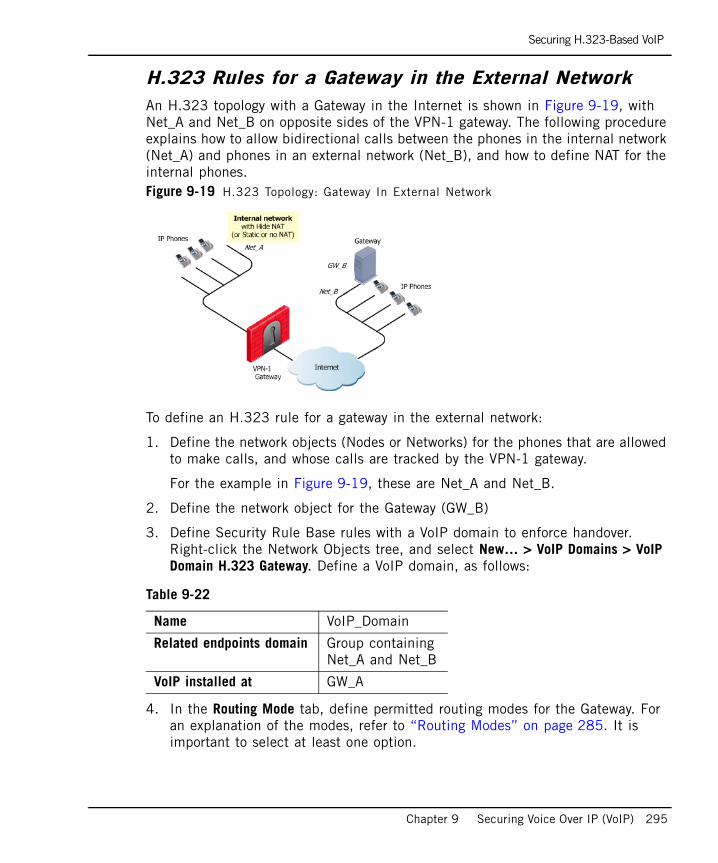
Securing H.323-Based VoIP
Chapter 9 Securing Voice Over IP (VoIP) 295
H.323 Rules for a Gateway in the External NetworkAn H.323 topology with a Gateway in the Internet is shown in Figure 9-19, with Net_A and Net_B on opposite sides of the VPN-1 gateway. The following procedure explains how to allow bidirectional calls between the phones in the internal network (Net_A) and phones in an external network (Net_B), and how to define NAT for the internal phones. Figure 9-19 H.323 Topology: Gateway In External Network
To define an H.323 rule for a gateway in the external network:
1. Define the network objects (Nodes or Networks) for the phones that are allowed to make calls, and whose calls are tracked by the VPN-1 gateway.
For the example in Figure 9-19, these are Net_A and Net_B.
2. Define the network object for the Gateway (GW_B)
3. Define Security Rule Base rules with a VoIP domain to enforce handover. Right-click the Network Objects tree, and select New… > VoIP Domains > VoIP Domain H.323 Gateway. Define a VoIP domain, as follows:
4. In the Routing Mode tab, define permitted routing modes for the Gateway. For an explanation of the modes, refer to “Routing Modes” on page 285. It is important to select at least one option.
Table 9-22
Name VoIP_Domain
Related endpoints domain Group containing Net_A and Net_B
VoIP installed at GW_A
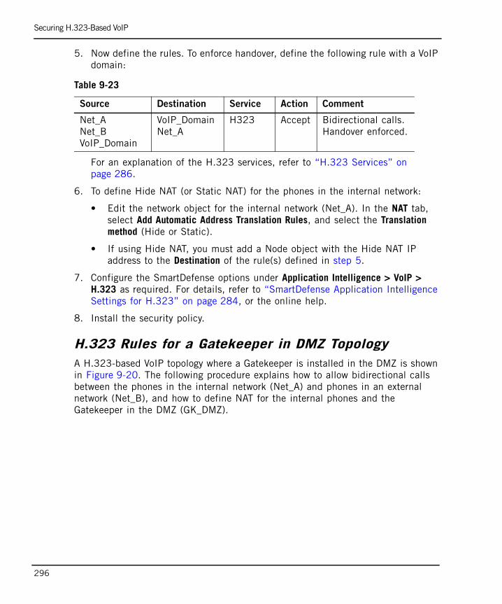
Securing H.323-Based VoIP
296
5. Now define the rules. To enforce handover, define the following rule with a VoIP domain:
For an explanation of the H.323 services, refer to “H.323 Services” on page 286.
6. To define Hide NAT (or Static NAT) for the phones in the internal network:
• Edit the network object for the internal network (Net_A). In the NAT tab, select Add Automatic Address Translation Rules, and select the Translation method (Hide or Static).
• If using Hide NAT, you must add a Node object with the Hide NAT IP address to the Destination of the rule(s) defined in step 5.
7. Configure the SmartDefense options under Application Intelligence > VoIP > H.323 as required. For details, refer to “SmartDefense Application Intelligence Settings for H.323” on page 284, or the online help.
8. Install the security policy.
H.323 Rules for a Gatekeeper in DMZ TopologyA H.323-based VoIP topology where a Gatekeeper is installed in the DMZ is shown in Figure 9-20. The following procedure explains how to allow bidirectional calls between the phones in the internal network (Net_A) and phones in an external network (Net_B), and how to define NAT for the internal phones and the Gatekeeper in the DMZ (GK_DMZ).
Table 9-23
Source Destination Service Action Comment
Net_ANet_BVoIP_Domain
VoIP_DomainNet_A
H323 Accept Bidirectional calls. Handover enforced.
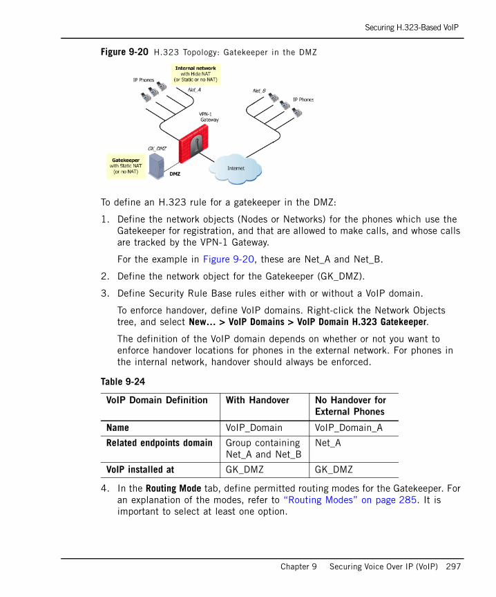
Securing H.323-Based VoIP
Chapter 9 Securing Voice Over IP (VoIP) 297
Figure 9-20 H.323 Topology: Gatekeeper in the DMZ
To define an H.323 rule for a gatekeeper in the DMZ:
1. Define the network objects (Nodes or Networks) for the phones which use the Gatekeeper for registration, and that are allowed to make calls, and whose calls are tracked by the VPN-1 Gateway.
For the example in Figure 9-20, these are Net_A and Net_B.
2. Define the network object for the Gatekeeper (GK_DMZ).
3. Define Security Rule Base rules either with or without a VoIP domain.
To enforce handover, define VoIP domains. Right-click the Network Objects tree, and select New… > VoIP Domains > VoIP Domain H.323 Gatekeeper.
The definition of the VoIP domain depends on whether or not you want to enforce handover locations for phones in the external network. For phones in the internal network, handover should always be enforced.
4. In the Routing Mode tab, define permitted routing modes for the Gatekeeper. For an explanation of the modes, refer to “Routing Modes” on page 285. It is important to select at least one option.
Table 9-24
VoIP Domain Definition With Handover No Handover for
External Phones
Name VoIP_Domain VoIP_Domain_A
Related endpoints domain Group containingNet_A and Net_B
Net_A
VoIP installed at GK_DMZ GK_DMZ

Securing H.323-Based VoIP
298
5. Now define the rules. For full handover enforcement, define the following rule:
If you do not want to enforce handover for the external phones (in Net_B), define the following rules:
When rules without a VoIP domain are defined, all connections other than H323_ras are only allowed to be peer to peer.
For an explanation of the H.323 services, refer to “H.323 Services” on page 286.
6. To define Hide NAT (or Static NAT) for the phones in the internal network:
• Edit the network object for Net_A. In the NAT tab, select Add Automatic Address Translation Rules, and select the Translation method (Hide or Static).
• If using Hide NAT, you must select the Hide behind IP address option, and type the IP address of the Hiding address of the phones in the internal network.
• If using Hide NAT, you must add a Node object with the Hide NAT IP address to the Destination of the rule(s) defined in step 5.
7. To define Static NAT for the Gatekeeper in the DMZ, add manual NAT rules, as follows:
• Create a Node object for the Static address of the Gatekeeper (for example: GK_DMZ_NATed).
Table 9-25
Source Destination Service Action Comment
VoIP_DomainNet_ANet_B
Net_ANet_BVoIP_Domain
H323_ras Accept
Bidirectional calls. Handover enforced.
Table 9-26
Source Destination Service Action Comment
Net_A, Net_B, GK_DMZ
Net_A, Net_B, GK_DMZ
H323_ras_only Accept Outgoing calls. No handover enforced.
Net_ANet_B
Net_ANet_B
H323 Accept No Handover enforced.
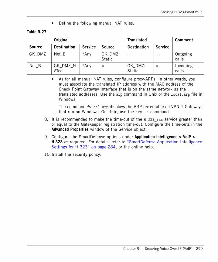
Securing H.323-Based VoIP
Chapter 9 Securing Voice Over IP (VoIP) 299
• Define the following manual NAT rules:
• As for all manual NAT rules, configure proxy-ARPs. In other words, you must associate the translated IP address with the MAC address of the Check Point Gateway interface that is on the same network as the translated addresses. Use the arp command in Unix or the local.arp file in Windows.
The command fw ctl arp displays the ARP proxy table on VPN-1 Gateways that run on Windows. On Unix, use the arp -a command.
8. It is recommended to make the time-out of the H.323_ras service greater than or equal to the Gatekeeper registration time-out. Configure the time-outs in the Advanced Properties window of the Service object.
9. Configure the SmartDefense options under Application Intelligence > VoIP > H.323 as required. For details, refer to “SmartDefense Application Intelligence Settings for H.323” on page 284, or the online help.
10. Install the security policy.
Table 9-27
Original Translated Comment
Source Destination Service Source Destination Service
GK_DMZ Net_B *Any GK_DMZ:Static
= = Outgoing calls
Net_B GK_DMZ_NATed
*Any = GK_DMZ:Static
= Incoming calls

Securing H.323-Based VoIP
300
H.323 Rules for a Gateway in DMZ TopologyA H.323-based VoIP topology where a Gateway is installed in the DMZ is shown in Figure 9-21. The following procedure explains how to allow bidirectional calls between the phones in the internal network (Net_A) and phones in an external network (Net_B), and how to define NAT for the internal phones and the Gateway in the DMZ (GK_DMZ). Figure 9-21 H.323 Topology: Gateway in the DMZ
To define an H.323 rule for a gateway in the DMZ:
1. Define the network objects (Nodes or Networks) for the phones that are allowed to make calls, and whose calls are tracked by the VPN-1 Gateway.
For the example in Figure 9-21, these are Net_A and Net_B.
2. Define the network object for the Gateway (GW_DMZ).
3. Define Security Rule Base rules with or without a VoIP domain to enforce handover. Right-click the Network Objects tree, and select New… > VoIP Domains > VoIP Domain H.323 Gateway.
4. In the Routing Mode tab, define permitted routing modes for the Gateway. For an explanation of the modes, refer to “Routing Modes” on page 285. It is important to select at least one option.
Table 9-28
VoIP Domain Definition With Handover
Name VoIP_Domain
Related endpoints domain Group containingNet_A and Net_B
VoIP installed at GK_DMZ
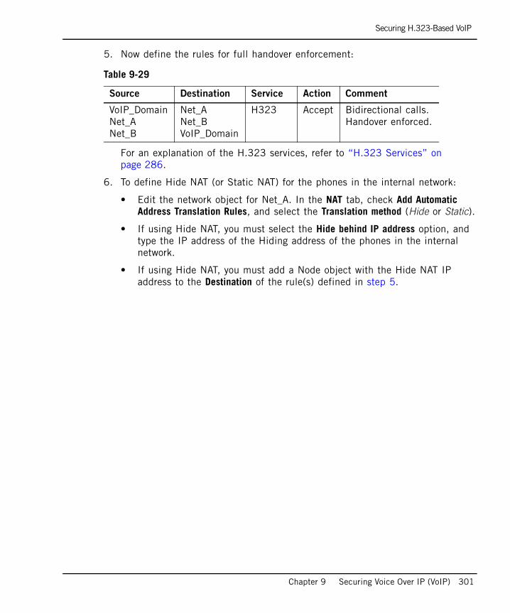
Securing H.323-Based VoIP
Chapter 9 Securing Voice Over IP (VoIP) 301
5. Now define the rules for full handover enforcement:
For an explanation of the H.323 services, refer to “H.323 Services” on page 286.
6. To define Hide NAT (or Static NAT) for the phones in the internal network:
• Edit the network object for Net_A. In the NAT tab, check Add Automatic Address Translation Rules, and select the Translation method (Hide or Static).
• If using Hide NAT, you must select the Hide behind IP address option, and type the IP address of the Hiding address of the phones in the internal network.
• If using Hide NAT, you must add a Node object with the Hide NAT IP address to the Destination of the rule(s) defined in step 5.
Table 9-29
Source Destination Service Action Comment
VoIP_DomainNet_ANet_B
Net_ANet_BVoIP_Domain
H323 Accept Bidirectional calls. Handover enforced.
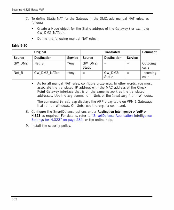
Securing H.323-Based VoIP
302
7. To define Static NAT for the Gateway in the DMZ, add manual NAT rules, as follows:
• Create a Node object for the Static address of the Gateway (for example: GW_DMZ_NATed).
• Define the following manual NAT rules:
• As for all manual NAT rules, configure proxy-arps. In other words, you must associate the translated IP address with the MAC address of the Check Point Gateway interface that is on the same network as the translated addresses. Use the arp command in Unix or the local.arp file in Windows.
The command fw ctl arp displays the ARP proxy table on VPN-1 Gateways that run on Windows. On Unix, use the arp -a command.
8. Configure the SmartDefense options under Application Intelligence > VoIP > H.323 as required. For details, refer to “SmartDefense Application Intelligence Settings for H.323” on page 284, or the online help.
9. Install the security policy.
Table 9-30
Original Translated Comment
Source Destination Service Source Destination Service
GW_DMZ Net_B *Any GW_DMZ:Static
= = Outgoing calls
Net_B GW_DMZ_NATed *Any = GW_DMZ:Static
= Incoming calls
Securing MGCP-Based VoIP
Chapter 9 Securing Voice Over IP (VoIP) 303
Securing MGCP-Based VoIP
The Need for MGCPRegular phones are relatively inexpensive because they do not need to be complex; they are fixed to a specific switch at a central switching location. IP phones and devices, on the other hand, are not fixed to a specific switch, so they must contain processors that enable them to function and be intelligent on their own, independent from a central switching location. This makes the terminal (phone or device) more complex and, therefore, more expensive.
The MGCP (Media Gateway Control Protocol) protocol is meant to simplify standards for VoIP by eliminating the need for complex, processor-intense IP telephony devices, thus simplifying and lowering the cost of these terminals.
MGCP interoperates with SIP and H.323, but does not replace them. MGCP converts audio signals carried on telephone circuits (PSTN) to data packets carried over the Internet or other packet networks.
The Need for MGCP page 303
MGCP Protocol and Devices page 304
MGCP Network Security and Application Intelligence page 305
Secured MGCP Topologies and NAT Support page 307
Synchronizing User Information page 308
Configuring MGCP-Based VoIP page 309
Note - Before reading this section, read “Introduction to the Check Point Solution for Secure VoIP” on page 249 to “Protocol-Specific Security” on page 258.
The MGCP protocol is described in this section only to the extent required to secure MGCP traffic using VPN-1.

Securing MGCP-Based VoIP
304
MGCP Protocol and DevicesMGCP is a protocol for controlling telephony gateways from external call control devices called Call Agents (also known as Media Gateway Controllers).
MGCP is a master/slave protocol, which means it assumes limited intelligence at the edge (endpoints) and intelligence at the core (Call Agent). In this it differs from SIP and H.323, which are peer-to-peer protocols.
The MGCP assumes that the call control devices, or Call Agents, will synchronize with each other to send commands to devices under their control called Media Gateways. Call Agents can also connect directly to IP Phones. The Media Gateways or IP Phones are expected to execute commands sent by the Call Agents. Figure 9-22 shows the MGCP elements and a simplified call control process.Figure 9-22 MGCP Elements
The Call Agent and Media Gateways are defined in SmartDashboard, usually as Node objects.
To allow MGCP conversations you need only create rules to allow the MGCP control signals through the VPN-1 gateway. There is no need to define a rule for the media that specifies which ports to open and which endpoints will talk. VPN-1 derives this information from the signalling. Given a particular VoIP signalling rule, VPN-1 automatically opens ports for the endpoint-to-endpoint RTP/RTCP media stream.
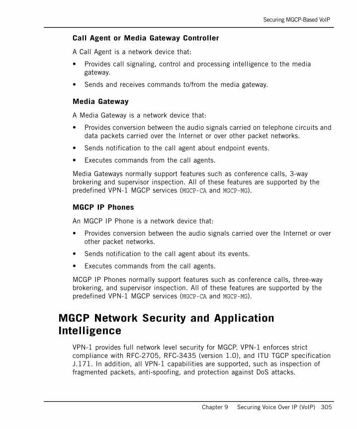
Securing MGCP-Based VoIP
Chapter 9 Securing Voice Over IP (VoIP) 305
Call Agent or Media Gateway Controller
A Call Agent is a network device that:
• Provides call signaling, control and processing intelligence to the media gateway.
• Sends and receives commands to/from the media gateway.
Media Gateway
A Media Gateway is a network device that:
• Provides conversion between the audio signals carried on telephone circuits and data packets carried over the Internet or over other packet networks.
• Sends notification to the call agent about endpoint events.
• Executes commands from the call agents.
Media Gateways normally support features such as conference calls, 3-way brokering and supervisor inspection. All of these features are supported by the predefined VPN-1 MGCP services (MGCP-CA and MGCP-MG).
MGCP IP Phones
An MGCP IP Phone is a network device that:
• Provides conversion between the audio signals carried over the Internet or over other packet networks.
• Sends notification to the call agent about its events.
• Executes commands from the call agents.
MCGP IP Phones normally support features such as conference calls, three-way brokering, and supervisor inspection. All of these features are supported by the predefined VPN-1 MGCP services (MGCP-CA and MGCP-MG).
MGCP Network Security and Application Intelligence
VPN-1 provides full network level security for MGCP. VPN-1 enforces strict compliance with RFC-2705, RFC-3435 (version 1.0), and ITU TGCP specification J.171. In addition, all VPN-1 capabilities are supported, such as inspection of fragmented packets, anti-spoofing, and protection against DoS attacks.

Securing MGCP-Based VoIP
306
VPN-1 restricts handover locations and controls signalling and data connections, as described in “VoIP Application Intelligence” on page 253.
SmartDefense can perform additional content security checks for MGCP connections, thereby providing a greater level of protection. MGCP-specific Application Intelligence security is configured via SmartDefense, under Application Intelligence > VoIP > MGCP. Three options are available:
• Blocked/Accepted Commands
• Verify MGCP Header Content
• Allow Multicast RTP Connections
Blocked/Accepted Commands There are nine predefined MGCP commands. Some commands are made by the Call Agent, and others by the Gateway, as shown in Table 9-31. It is possible to allow or disallow any command as dictated by the security needs.
In addition, it is possible to define additional proprietary commands, as well as whether to allow or block those commands. By default, all undefined commands are blocked.
VPN-1 verifies that the new commands are RFC compliant.
MGCP packets contain an optional SDP header. This header contains information such as the destination port number, the destination IP address and the media type (audio or video). The predefined MGCP commands MDCX and CRCX have an SDP header.
Table 9-31 MGCP commands
Call Agent Commands Gateway Commands
EndpointConfiguration (EPCF) Notify (NTFY)
NotificationRequest (RQNT) DeleteConnection (DLXC)
CreateConnection (CRCX) RestartInProgress (RSIP)
ModifyConnection (MDCX)
DeleteConnection (DLCX)
AuditEndpoint (AUEP)
AuditConnection (AUCX)
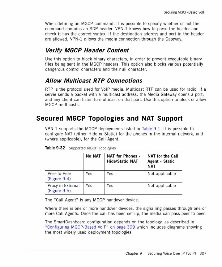
Securing MGCP-Based VoIP
Chapter 9 Securing Voice Over IP (VoIP) 307
When defining an MGCP command, it is possible to specify whether or not the command contains an SDP header. VPN-1 knows how to parse the header and check it has the correct syntax. If the destination address and port in the header are allowed, VPN-1 allows the media connection through the Gateway.
Verify MGCP Header ContentUse this option to block binary characters, in order to prevent executable binary files being sent in the MGCP headers. This option also blocks various potentially dangerous control characters and the null character.
Allow Multicast RTP ConnectionsRTP is the protocol used for VoIP media. Multicast RTP can be used for radio. If a server sends a packet with a multicast address, the Media Gateway opens a port, and any client can listen to multicast on that port. Use this option to block or allow MGCP multicasts.
Secured MGCP Topologies and NAT SupportVPN-1 supports the MGCP deployments listed in Table 9-1. It is possible to configure NAT (either Hide or Static) for the phones in the internal network, and (where applicable), for the Call Agent.
The “Call Agent” is any MGCP handover device.
Where there is one or more handover devices, the signalling passes through one or more Call Agents. Once the call has been set up, the media can pass peer to peer.
The SmartDashboard configuration depends on the topology, as described in “Configuring MGCP-Based VoIP” on page 309 which includes diagrams showing the most widely used deployment topologies.
Table 9-32 Supported MGCP Topologies
No NAT NAT for Phones -
Hide/Static NAT
NAT for the Call
Agent - Static
NAT
Peer-to-Peer (Figure 9-4)
Yes Yes Not applicable
Proxy in External (Figure 9-5)
Yes Yes Not applicable
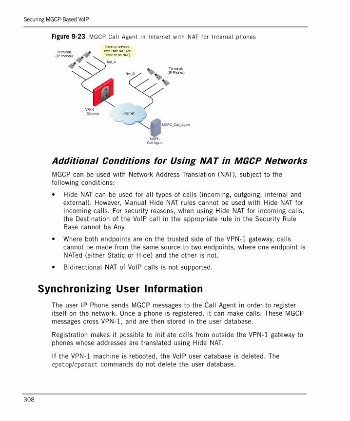
Securing MGCP-Based VoIP
308
Figure 9-23 MGCP Call Agent in Internet with NAT for Internal phones
Additional Conditions for Using NAT in MGCP NetworksMGCP can be used with Network Address Translation (NAT), subject to the following conditions:
• Hide NAT can be used for all types of calls (incoming, outgoing, internal and external). However, Manual Hide NAT rules cannot be used with Hide NAT for incoming calls. For security reasons, when using Hide NAT for incoming calls, the Destination of the VoIP call in the appropriate rule in the Security Rule Base cannot be Any.
• Where both endpoints are on the trusted side of the VPN-1 gateway, calls cannot be made from the same source to two endpoints, where one endpoint is NATed (either Static or Hide) and the other is not.
• Bidirectional NAT of VoIP calls is not supported.
Synchronizing User InformationThe user IP Phone sends MGCP messages to the Call Agent in order to register itself on the network. Once a phone is registered, it can make calls. These MGCP messages cross VPN-1, and are then stored in the user database.
Registration makes it possible to initiate calls from outside the VPN-1 gateway to phones whose addresses are translated using Hide NAT.
If the VPN-1 machine is rebooted, the VoIP user database is deleted. The cpstop/cpstart commands do not delete the user database.
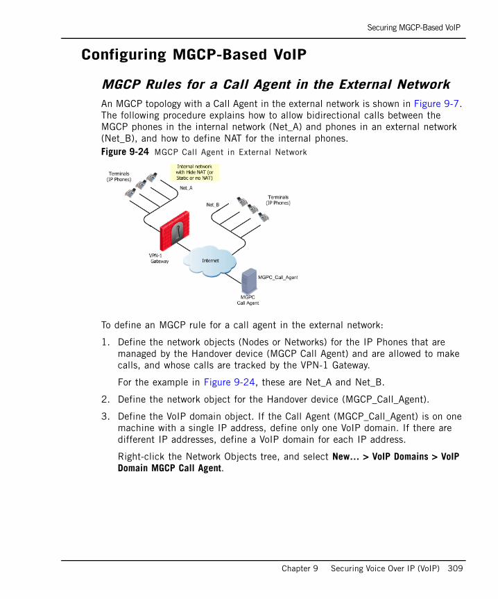
Securing MGCP-Based VoIP
Chapter 9 Securing Voice Over IP (VoIP) 309
Configuring MGCP-Based VoIP
MGCP Rules for a Call Agent in the External NetworkAn MGCP topology with a Call Agent in the external network is shown in Figure 9-7. The following procedure explains how to allow bidirectional calls between the MGCP phones in the internal network (Net_A) and phones in an external network (Net_B), and how to define NAT for the internal phones. Figure 9-24 MGCP Call Agent in External Network
To define an MGCP rule for a call agent in the external network:
1. Define the network objects (Nodes or Networks) for the IP Phones that are managed by the Handover device (MGCP Call Agent) and are allowed to make calls, and whose calls are tracked by the VPN-1 Gateway.
For the example in Figure 9-24, these are Net_A and Net_B.
2. Define the network object for the Handover device (MGCP_Call_Agent).
3. Define the VoIP domain object. If the Call Agent (MGCP_Call_Agent) is on one machine with a single IP address, define only one VoIP domain. If there are different IP addresses, define a VoIP domain for each IP address.
Right-click the Network Objects tree, and select New… > VoIP Domains > VoIP Domain MGCP Call Agent.
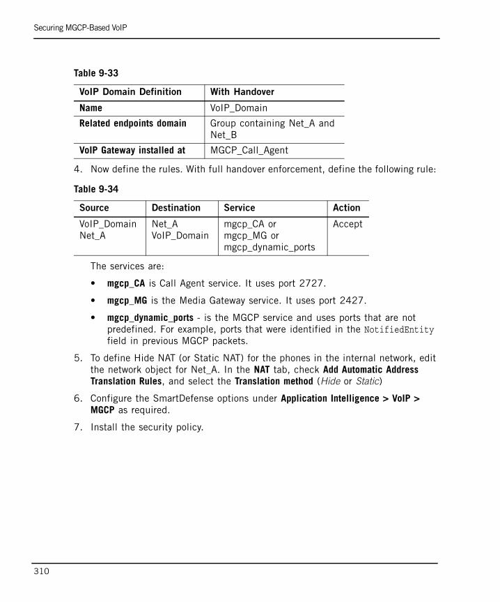
Securing MGCP-Based VoIP
310
4. Now define the rules. With full handover enforcement, define the following rule:
The services are:
• mgcp_CA is Call Agent service. It uses port 2727.
• mgcp_MG is the Media Gateway service. It uses port 2427.
• mgcp_dynamic_ports - is the MGCP service and uses ports that are not predefined. For example, ports that were identified in the NotifiedEntity field in previous MGCP packets.
5. To define Hide NAT (or Static NAT) for the phones in the internal network, edit the network object for Net_A. In the NAT tab, check Add Automatic Address Translation Rules, and select the Translation method (Hide or Static)
6. Configure the SmartDefense options under Application Intelligence > VoIP > MGCP as required.
7. Install the security policy.
Table 9-33
VoIP Domain Definition With Handover
Name VoIP_Domain
Related endpoints domain Group containing Net_A and Net_B
VoIP Gateway installed at MGCP_Call_Agent
Table 9-34
Source Destination Service Action
VoIP_Domain Net_A
Net_A VoIP_Domain
mgcp_CA or mgcp_MG or mgcp_dynamic_ports
Accept
Securing SCCP-Based VoIP
Chapter 9 Securing Voice Over IP (VoIP) 311
Securing SCCP-Based VoIP
In This Section
The SCCP ProtocolMany Cisco® devices use the Cisco proprietary VoIP protocol, SCCP (Skinny Client Control Protocol). The SCCP protocol is also licensed to a number of Cisco partners.
SCCP uses TCP on port 2000 for the control signals. Media is transmitted using RTP over UDP to and from a SCCP client or H.323 terminal for audio.
The protocol headers are binary headers (unlike MGCP, for example, which uses text headers).
The SCCP protocol defines hundreds of messages. They can be broadly divided into three groups:
• Registration and management messages.
• Media Control Messages.
• Call Control Messages.
Note - Before reading this section, read “Introduction to the Check Point Solution for Secure VoIP” on page 249 to “Protocol-Specific Security” on page 258.
The SCCP protocol is described in this section only to the extent required to secure SCCP traffic using VPN-1.
The SCCP Protocol page 311
SCCP Devices page 312
SCCP Network Security and Application Intelligence page 312
ClusterXL Support for SCCP page 313
Configuring SCCP-Based VoIP page 313

Securing SCCP-Based VoIP
312
SCCP DevicesSCCP has a centralized call-control architecture. The CallManager manages SCCP clients (VoIP endpoints), which can be IP Phones or Cisco ATA analog phone adapters. The CallManager controls all the features of the endpoints. It requests information, such as the station capabilities, and sends information, such as the button template and the date/time, to the VoIP endpoints.
The CallManagers are defined in SmartDashboard, usually as Node objects. The networks containing directly-managed IP Phones are also defined in SmartDashboard. There is normally no need to define network objects for individual phones. Cisco ATA devices that are managed by a CallManager must be defined in SmartDashboard, but the connected analog phones are not defined.
To allow SCCP conversations, you need only create rules to allow the SCCP control signals through the VPN-1 Gateway. There is no need to define a rule for the media that specifies which ports to open and which endpoints will talk. VPN-1 derives this information from the signalling. Given a particular VoIP signalling rule, VPN-1 automatically opens ports for the endpoint-to-endpoint RTP/RTCP media stream.
SCCP Network Security and Application Intelligence
VPN-1 provides full connectivity and network level and security for SCCP-based VoIP communication. All SCCP traffic is inspected and legitimate traffic is allowed to pass while attacks are blocked. All VPN-1 capabilities are supported, such as anti- spoofing and protection against DoS attacks. Fragmented packets are examined and secured using kernel-based streaming. However, NAT on SCCP devices is not supported.
VPN-1 restricts handover locations, and controls signalling and data connections, as described in “VoIP Application Intelligence” on page 253.
VPN-1 tracks state and verifies that the state is valid for all SCCP message. For a number of key messages, it also verifies of existence and correctness of the message parameters.
SmartDefense can perform additional content security checks for SCCP connections, thereby providing a greater level of protection.
Under Application Intelligence > VoIP > SCCP, two options are available:
• Verify SCCP Header Content blocks various potentially dangerous control characters, and the null character.
Securing SCCP-Based VoIP
Chapter 9 Securing Voice Over IP (VoIP) 313
• Block Multicast RTP Connections blocks SCCP multicasts. RTP is the protocol used for VoIP media. Multicast RTP can be used for radio. If a server sends a packet with a multicast address, the CallManager opens a port, and any client can listen to multicast on that port.
ClusterXL Support for SCCPSCCP calls can be made across a ClusterXL Gateway cluster. However, calls do not survive failover if the failover occurs while the call is being set up.
Configuring SCCP-Based VoIPTo configure SCCP-Based VoIP:
1. Configure the SmartDefense settings for SCCP under Application Intelligence > VoIP > SCCP.
2. Define the network objects (Nodes or Networks) for the Cisco ATA devices or IP Phones that are controlled by the CallManagers.
3. Define a Group object for the VoIP endpoint domain. This is a group all the network objects defined in step 2.
4. Define the network object for the machine on which the CallManager is installed.
5. Define the VoIP domain object.
From the SmartDashboard menu, select Manage > Network Objects > New… > VoIP Domains > VoIP Domain SCCP. Give the Domain object a Name. For the Related endpoints domain, select the Group object defined in step 3. For the VoIP installed at option, select the network object defined in step 4.
6. Define the VoIP Rule(s) that are appropriate for the topology. Place the predefined SCCP service in the Service column of the rule. SCCP interoperates with other VoIP protocols. However, SCCP configuration is independent of the other VoIP protocol configuration. Define separate rules for SCCP and the other VoIP protocols.
The rules depend on the network topology. For details, refer to the following sections:
• “SCCP Rules for a CallManager in the DMZ” on page 314.
• “SCCP Rules for a CallManager in the Internal Network” on page 315.
• “SCCP Rules for a CallManager in an External Network” on page 316.
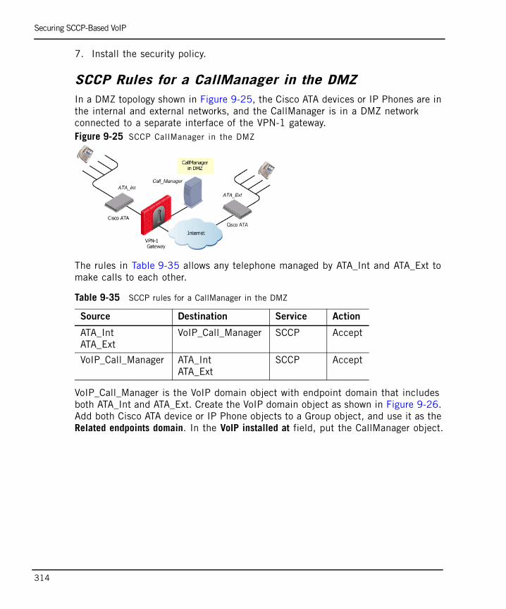
Securing SCCP-Based VoIP
314
7. Install the security policy.
SCCP Rules for a CallManager in the DMZIn a DMZ topology shown in Figure 9-25, the Cisco ATA devices or IP Phones are in the internal and external networks, and the CallManager is in a DMZ network connected to a separate interface of the VPN-1 gateway. Figure 9-25 SCCP CallManager in the DMZ
The rules in Table 9-35 allows any telephone managed by ATA_Int and ATA_Ext to make calls to each other.
VoIP_Call_Manager is the VoIP domain object with endpoint domain that includes both ATA_Int and ATA_Ext. Create the VoIP domain object as shown in Figure 9-26. Add both Cisco ATA device or IP Phone objects to a Group object, and use it as the Related endpoints domain. In the VoIP installed at field, put the CallManager object.
Table 9-35 SCCP rules for a CallManager in the DMZ
Source Destination Service Action
ATA_IntATA_Ext
VoIP_Call_Manager SCCP Accept
VoIP_Call_Manager ATA_IntATA_Ext
SCCP Accept
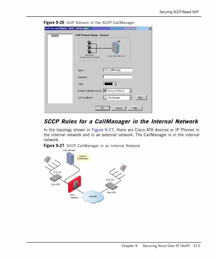
Securing SCCP-Based VoIP
Chapter 9 Securing Voice Over IP (VoIP) 315
Figure 9-26 VoIP Domain of the SCCP CallManager
SCCP Rules for a CallManager in the Internal NetworkIn the topology shown in Figure 9-27, there are Cisco ATA devices or IP Phones in the internal network and in an external network. The CallManager is in the internal network. Figure 9-27 SCCP CallManager in an Internal Network
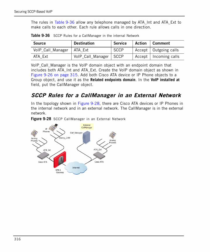
Securing SCCP-Based VoIP
316
The rules in Table 9-36 allow any telephone managed by ATA_Int and ATA_Ext to make calls to each other. Each rule allows calls in one direction.
VoIP_Call_Manager is the VoIP domain object with an endpoint domain that includes both ATA_Int and ATA_Ext. Create the VoIP domain object as shown in Figure 9-26 on page 315. Add both Cisco ATA device or IP Phone objects to a Group object, and use it as the Related endpoints domain. In the VoIP installed at field, put the CallManager object.
SCCP Rules for a CallManager in an External NetworkIn the topology shown in Figure 9-28, there are Cisco ATA devices or IP Phones in the internal network and in an external network. The CallManager is in the external network.Figure 9-28 SCCP CallManager in an External Network
Table 9-36 SCCP Rules for a CallManager in the internal Network
Source Destination Service Action Comment
VoIP_Call_Manager ATA_Ext SCCP Accept Outgoing calls
ATA_Ext VoIP_Call_Manager SCCP Accept Incoming calls
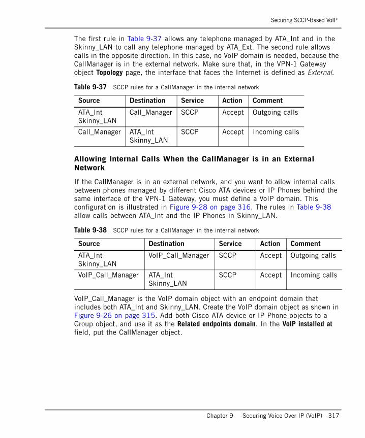
Securing SCCP-Based VoIP
Chapter 9 Securing Voice Over IP (VoIP) 317
The first rule in Table 9-37 allows any telephone managed by ATA_Int and in the Skinny_LAN to call any telephone managed by ATA_Ext. The second rule allows calls in the opposite direction. In this case, no VoIP domain is needed, because the CallManager is in the external network. Make sure that, in the VPN-1 Gateway object Topology page, the interface that faces the Internet is defined as External.
Allowing Internal Calls When the CallManager is in an External Network
If the CallManager is in an external network, and you want to allow internal calls between phones managed by different Cisco ATA devices or IP Phones behind the same interface of the VPN-1 Gateway, you must define a VoIP domain. This configuration is illustrated in Figure 9-28 on page 316. The rules in Table 9-38 allow calls between ATA_Int and the IP Phones in Skinny_LAN.
VoIP_Call_Manager is the VoIP domain object with an endpoint domain that includes both ATA_Int and Skinny_LAN. Create the VoIP domain object as shown in Figure 9-26 on page 315. Add both Cisco ATA device or IP Phone objects to a Group object, and use it as the Related endpoints domain. In the VoIP installed at field, put the CallManager object.
Table 9-37 SCCP rules for a CallManager in the internal network
Source Destination Service Action Comment
ATA_IntSkinny_LAN
Call_Manager SCCP Accept Outgoing calls
Call_Manager ATA_IntSkinny_LAN
SCCP Accept Incoming calls
Table 9-38 SCCP rules for a CallManager in the internal network
Source Destination Service Action Comment
ATA_IntSkinny_LAN
VoIP_Call_Manager SCCP Accept Outgoing calls
VoIP_Call_Manager ATA_IntSkinny_LAN
SCCP Accept Incoming calls

Securing SCCP-Based VoIP
318
319
Chapter 10Securing Instant Messaging Applications
In This Chapter
The Need to Secure Instant Messenger Applications page 320
Introduction to Instant Messenger Security page 321
Understanding Instant Messenger Security page 322
NAT Support for MSN Messenger over SIP page 323
NAT Support for MSN Messenger over MSNMS page 324
Logging Instant Messenger Applications page 324
Configuring SIP-based Instant Messengers page 325
Configuring MSN Messenger over MSNMS page 327
Configuring Skype, Yahoo and ICQ and Other Instant Messengers page 328
The Need to Secure Instant Messenger Applications
320
The Need to Secure Instant Messenger Applications
Common Instant Messenger capabilities include file transfer, remote collaboration, and remote assistance. File transfers, for example, are a potential source of virus and worm infections. Traditional content filters do not look for Instant Messenger traffic and, as a result most of the new worms and Trojans, use Instant Messenger and peer-to-peer networks to propagate. Remote assistance allows help desk staff to control the PC to improve service and reduce MIS costs. However, it can also be used by hackers to take control of a remote computer.
Instant Messaging protocols themselves have vulnerabilities that can be exploited to cause a Denial of Service attack. For example, passing an overly long user name and password for authorization for some applications may cause a buffer overflow that could bring down the Instant Messenger server.
SIP is emerging as the de-facto standard for instant messaging applications in the enterprise. There are several known security issues associated with SIP-based instant messaging applications. These are similar to the vulnerabilities associated with SIP when used for Voice Over IP (VoIP), with additional vulnerabilities caused by the nature of Instant Messengers and the way that they are used in the enterprise.
Introduction to Instant Messenger Security
Chapter 10 Securing Instant Messaging Applications 321
Introduction to Instant Messenger SecurityInstant Messenger applications allow communication and collaboration between users employing various communication modes, such as Instant Messaging, Voice and Video, Application Sharing, White board, File Transfer, and Remote Assistance.
Firewall and SmartDefense provide powerful and flexible security for Instant Messengers. MSN Messenger in particular, both in its SIP mode of operation, and using the native MSNMS protocol, can be secured with an extra level of granularity.
It is possible to selectively block audio, video or other selected capabilities of MSN Messenger. In addition, the audio and video streams of any SIP-based Instant Messaging application can be blocked. The Security Rule Base can be used to allow communication to and from specified locations.
Firewall and SmartDefense secure MSN Messenger over SIP topologies. MSN Messenger over SIP requires the use of a SIP proxy, and does not support endpoint -to-endpoint calls.

Understanding Instant Messenger Security
322
Understanding Instant Messenger SecurityTo understand the principles of securing SIP-based Instant Messenger communication, refer to Chapter 9, “Securing Voice Over IP (VoIP)”: “Introduction to the Check Point Solution for Secure VoIP” on page 249 to “Securing SIP-Based VoIP” on page 259 (inclusive).
VPN-1 dynamically opens ports for the services used by Instant Messenger applications. It keeps those ports open only for as long as required, and closes them as soon as the call ends, without waiting for a time-out. The order and direction of the packets is also enforced.
For detailed information about MSN Messenger and the protocols it uses, visit the following Microsoft web pages:
• http://www.microsoft.com/technet/prodtechnol/winxppro/evaluate/insid01.mspx
• http://www.microsoft.com/technet/prodtechnol/winxppro/plan/rtcprot.mspx(recommended for technical reference)
Some peer-to-peer applications also have Instant Messenger capabilities, which can be blocked or allowed. For details, see the HTML pages and online help for the SmartDefense Application Intelligence > Peer to Peer category.

NAT Support for MSN Messenger over SIP
Chapter 10 Securing Instant Messaging Applications 323
NAT Support for MSN Messenger over SIPThe Firewall and SmartDefense components of VPN-1 allow all SIP-based MSN Messenger applications to work seamlessly with Static Network Address Translation (NAT). Hide NAT is fully supported for Instant Messenger (chat) and audio connections. For other MSN Messenger applications, some Hide NAT operations are not supported due to the inconsistent behavior of MSN Messenger. Table 10-1 shows how Hide NAT can be used with SIP-based MSN Messenger applications.
Table 10-1 Support for Hide NAT with SIP-Based MSN Messenger Capabilities
Hide NAT Instant Messaging
Application Sharingand Whiteboard
File Transfer and Remote Assistance
Audio Video andAudio
Internal –> External(outbound traffic)
Yes Yes No Yes No
External –> Internal(inbound traffic)
Yes No Yes Yes No
Internal –> Internal(internal traffic)
Yes Yes Yes Yes Yes
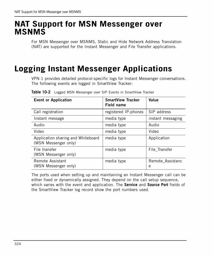
NAT Support for MSN Messenger over MSNMS
324
NAT Support for MSN Messenger over MSNMS
For MSN Messenger over MSNMS, Static and Hide Network Address Translation (NAT) are supported for the Instant Messenger and File Transfer applications.
Logging Instant Messenger ApplicationsVPN-1 provides detailed protocol-specific logs for Instant Messenger conversations. The following events are logged in SmartView Tracker:
The ports used when setting up and maintaining an Instant Messenger call can be either fixed or dynamically assigned. They depend on the call setup sequence, which varies with the event and application. The Service and Source Port fields of the SmartView Tracker log record show the port numbers used.
Table 10-2 Logged MSN Messenger over SIP Events in SmartView Tracker
Event or Application SmartView Tracker
Field name
Value
Call registration registered IP-phones SIP address
Instant message media type instant messaging
Audio media type Audio
Video media type Video
Application sharing and Whiteboard (MSN Messenger only)
media type Application
File transfer (MSN Messenger only)
media type File_Transfer
Remote Assistant (MSN Messenger only)
media type Remote_Assistance
Configuring SIP-based Instant Messengers
Chapter 10 Securing Instant Messaging Applications 325
Configuring SIP-based Instant Messengers The Firewall and SmartDefense components make it possible to block or allow all SIP-based Instant Messenger applications. For MSN Messenger over SIP, additional granular control is possible.
To completely block MSN Messenger over SIP and other SIP-based Instant Messenger applications, including the core instant messaging capabilities, do not allow the SIP service in the Security Rule Base.
To selectively block SIP-based Instant Messenger applications (while allowing the core instant Messaging capabilities):
1. Create a network group object that contains all clients that are allowed to work with the SIP proxy (call it allowed_phones, for example).
2. Create a VoIP domain object for the SIP proxy (call it SIP_domain, for example).
3. Define the rule that includes all the services that you wish to allow. The rule in Table 10-3 includes all the relevant services, and allows calls in both directions.
The relevant services are:
• sip allows the use of a proxy server and enforces handover via a VoIP Domain. See “SIP Services” on page 267.
• sip_dynamic_ports is required for all SIP-based instant messaging applications.
• T.120 is needed for application sharing and whiteboard applications.
• MSN_Messenger_File_Transfer is used for the MSN Messenger File Transfer application.
Note - To understand how to configure SmartDashboard for a SIP Proxy topology, it is highly recommended to first read “Configuring SIP-Based VoIP” on page 269.
Table 10-3 Example rule allowing SIP-based Instant Messengers
Source Destination Service Action Action
allowed_phonesSIP_domain
SIP_domainallowed_phones
sipsip_dynamic_portsT.120MSN_Messenger_File_Transfer
Accept Log
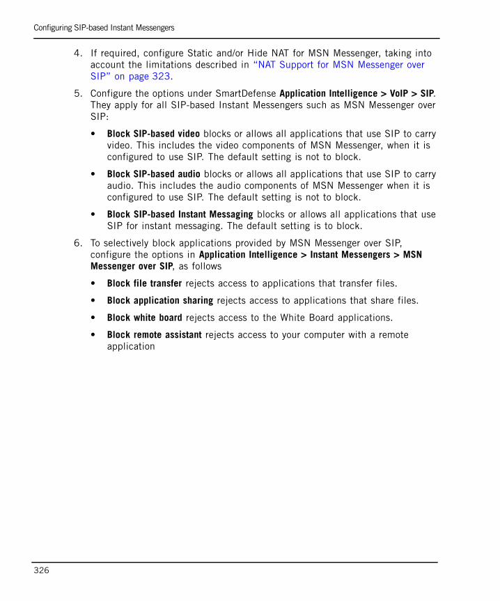
Configuring SIP-based Instant Messengers
326
4. If required, configure Static and/or Hide NAT for MSN Messenger, taking into account the limitations described in “NAT Support for MSN Messenger over SIP” on page 323.
5. Configure the options under SmartDefense Application Intelligence > VoIP > SIP. They apply for all SIP-based Instant Messengers such as MSN Messenger over SIP:
• Block SIP-based video blocks or allows all applications that use SIP to carry video. This includes the video components of MSN Messenger, when it is configured to use SIP. The default setting is not to block.
• Block SIP-based audio blocks or allows all applications that use SIP to carry audio. This includes the audio components of MSN Messenger when it is configured to use SIP. The default setting is not to block.
• Block SIP-based Instant Messaging blocks or allows all applications that use SIP for instant messaging. The default setting is to block.
6. To selectively block applications provided by MSN Messenger over SIP, configure the options in Application Intelligence > Instant Messengers > MSN Messenger over SIP, as follows
• Block file transfer rejects access to applications that transfer files.
• Block application sharing rejects access to applications that share files.
• Block white board rejects access to the White Board applications.
• Block remote assistant rejects access to your computer with a remote application
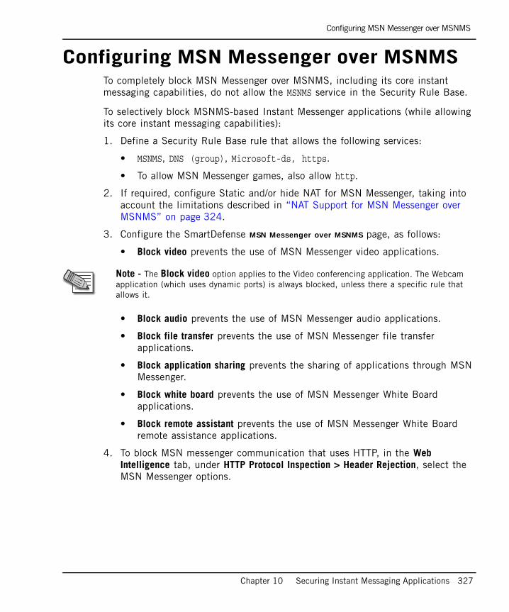
Configuring MSN Messenger over MSNMS
Chapter 10 Securing Instant Messaging Applications 327
Configuring MSN Messenger over MSNMSTo completely block MSN Messenger over MSNMS, including its core instant messaging capabilities, do not allow the MSNMS service in the Security Rule Base.
To selectively block MSNMS-based Instant Messenger applications (while allowing its core instant messaging capabilities):
1. Define a Security Rule Base rule that allows the following services:
• MSNMS, DNS (group), Microsoft-ds, https.
• To allow MSN Messenger games, also allow http.
2. If required, configure Static and/or hide NAT for MSN Messenger, taking into account the limitations described in “NAT Support for MSN Messenger over MSNMS” on page 324.
3. Configure the SmartDefense MSN Messenger over MSNMS page, as follows:
• Block video prevents the use of MSN Messenger video applications.
• Block audio prevents the use of MSN Messenger audio applications.
• Block file transfer prevents the use of MSN Messenger file transfer applications.
• Block application sharing prevents the sharing of applications through MSN Messenger.
• Block white board prevents the use of MSN Messenger White Board applications.
• Block remote assistant prevents the use of MSN Messenger White Board remote assistance applications.
4. To block MSN messenger communication that uses HTTP, in the Web Intelligence tab, under HTTP Protocol Inspection > Header Rejection, select the MSN Messenger options.
Note - The Block video option applies to the Video conferencing application. The Webcam application (which uses dynamic ports) is always blocked, unless there a specific rule that allows it.
Configuring Skype, Yahoo and ICQ and Other Instant Messengers
328
Configuring Skype, Yahoo and ICQ and Other Instant Messengers
• To allow Skype, Yahoo and ICQ and other Instant Messenger applications, follow the instructions provided by the application vendors.
• To block Skype, Yahoo! Messenger and ICQ, configure the SmartDefense options under Application Intelligence > Instant Messengers.
• Some peer-to-peer applications also have instant messaging capabilities. Block or allow peer-to-peer applications using the options in Application Intelligence > Peer to Peer.

329
Chapter 11Microsoft Networking Services (CIFS) Security
In This Chapter
Securing Microsoft Networking Services (CIFS) page 330
Restricting Access to Servers and Shares (CIFS Resource) page 331
Securing Microsoft Networking Services (CIFS)
330
Securing Microsoft Networking Services (CIFS)
CIFS (Common Internet File System) is a protocol used to request file and print services from server systems over a network. CIFS is an extension of the Server Message Block (SMB) protocol. CIFS is used as the underlying transport layer for the NETBIOS session (nbsession) service over TCP using port 139. In Windows networking, CIFS is used over the Microsoft-DS protocol (port 445) for networking and file sharing. More information on CIFS can be found at http://samba.org/cifs/.
By default, a Windows server has default shares open for administrative purposes (C$, ADMIN$, PRINT$) and is therefore an easy target for internal attacks, such as brute-force password attacks on file servers.
VPN-1 secures Microsoft Networking Services in the Inspection Module, without requiring a Security server. This meets the high performance requirements of LAN security (Fast Ethernet and Gigabit Ethernet).
The CIFS resource can be used to enforce the following security checks on CIFS connections:
• Verifying the correctness of the protocol.
• Preventing CIFS and NETBIOS messages issued by the client from pointing to beyond message boundaries.
• Restricting access to a list of CIFS servers and disk shares.
• Logging disk share access.
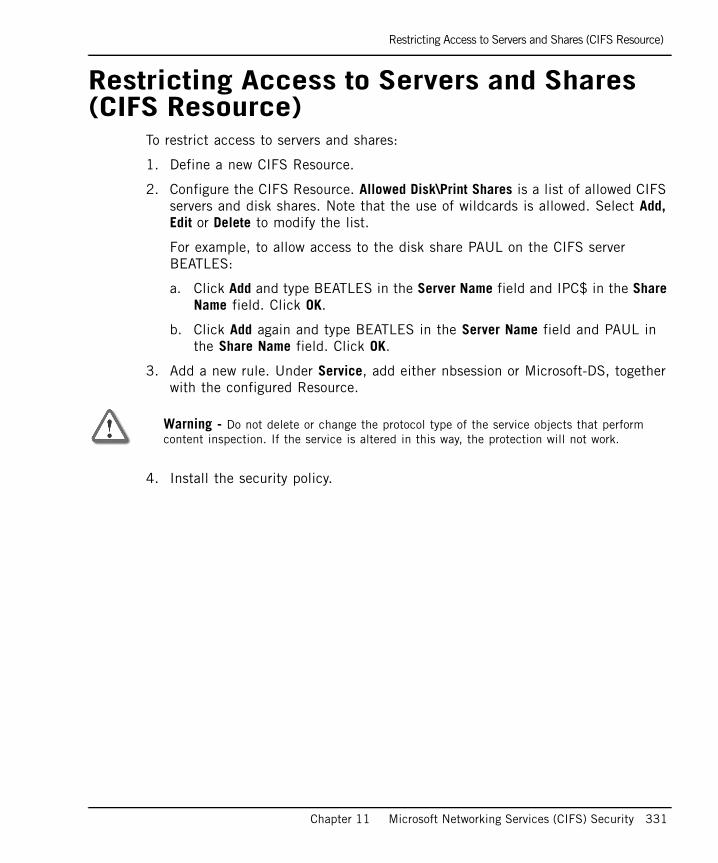
Restricting Access to Servers and Shares (CIFS Resource)
Chapter 11 Microsoft Networking Services (CIFS) Security 331
Restricting Access to Servers and Shares (CIFS Resource)
To restrict access to servers and shares:
1. Define a new CIFS Resource.
2. Configure the CIFS Resource. Allowed Disk\Print Shares is a list of allowed CIFS servers and disk shares. Note that the use of wildcards is allowed. Select Add, Edit or Delete to modify the list.
For example, to allow access to the disk share PAUL on the CIFS server BEATLES:
a. Click Add and type BEATLES in the Server Name field and IPC$ in the Share Name field. Click OK.
b. Click Add again and type BEATLES in the Server Name field and PAUL in the Share Name field. Click OK.
3. Add a new rule. Under Service, add either nbsession or Microsoft-DS, together with the configured Resource.
4. Install the security policy.
Warning - Do not delete or change the protocol type of the service objects that perform content inspection. If the service is altered in this way, the protection will not work.

Restricting Access to Servers and Shares (CIFS Resource)
332
333
Chapter 12FTP Security
In This Chapter
Introduction to FTP Content Security page 334
FTP Enforcement by the VPN-1 Kernel page 334
FTP Enforcement by the FTP Security Server page 335
Configuring Restricted Access to Specific Directories page 337
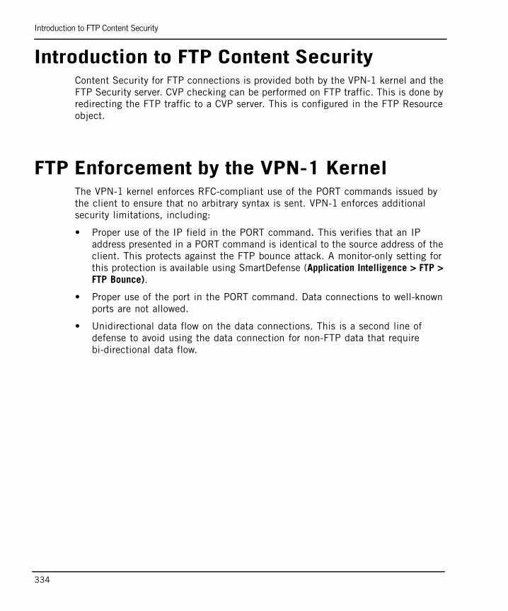
Introduction to FTP Content Security
334
Introduction to FTP Content SecurityContent Security for FTP connections is provided both by the VPN-1 kernel and the FTP Security server. CVP checking can be performed on FTP traffic. This is done by redirecting the FTP traffic to a CVP server. This is configured in the FTP Resource object.
FTP Enforcement by the VPN-1 Kernel The VPN-1 kernel enforces RFC-compliant use of the PORT commands issued by the client to ensure that no arbitrary syntax is sent. VPN-1 enforces additional security limitations, including:
• Proper use of the IP field in the PORT command. This verifies that an IP address presented in a PORT command is identical to the source address of the client. This protects against the FTP bounce attack. A monitor-only setting for this protection is available using SmartDefense (Application Intelligence > FTP > FTP Bounce).
• Proper use of the port in the PORT command. Data connections to well-known ports are not allowed.
• Unidirectional data flow on the data connections. This is a second line of defense to avoid using the data connection for non-FTP data that require bi-directional data flow.
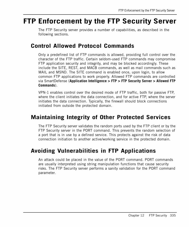
FTP Enforcement by the FTP Security Server
Chapter 12 FTP Security 335
FTP Enforcement by the FTP Security ServerThe FTP Security server provides a number of capabilities, as described in the following sections.
Control Allowed Protocol CommandsOnly a predefined list of FTP commands is allowed, providing full control over the character of the FTP traffic. Certain seldom-used FTP commands may compromise FTP application security and integrity, and may be blocked accordingly. These include the SITE, REST, and MACB commands, as well as mail commands such as MAIL and MSND. The SITE command is enabled once, upon login, to allow common FTP applications to work properly. Allowed FTP commands are controlled via SmartDefense (Application Intelligence > FTP > FTP Security Server > Allowed FTP Commands).
VPN-1 enables control over the desired mode of FTP traffic, both for passive FTP, where the client initiates the data connection, and for active FTP, where the server initiates the data connection. Typically, the firewall should block connections initiated from outside the protected domain.
Maintaining Integrity of Other Protected ServicesThe FTP Security server validates the random ports used by the FTP client or by the FTP Security server in the PORT command. This prevents the random selection of a port that is in use by a defined service. This protects against the risk of data connection initiation to another active/working service in the protected domain.
Avoiding Vulnerabilities in FTP ApplicationsAn attack could be placed in the value of the PORT command. PORT commands are usually interpreted using string manipulation functions that cause security risks. The FTP Security server performs a sanity validation for the PORT command parameter.
FTP Enforcement by the FTP Security Server
336
Content Security via the FTP ResourceFTP connections can be inspected for viruses and malicious content through integration with third-party, OPSEC-certified CVP and UFP applications. For additional information, refer to “Using CVP for Virus Scanning on FTP Connections” on page 346.
Configuring Restricted Access to Specific Directories
Chapter 12 FTP Security 337
Configuring Restricted Access to Specific Directories
It is possible to allow only file downloads (by specifying GET as an allowed method) or only uploads (by specifying PUT as an allowed method), or both, in an FTP resource.
It is also possible to restrict connections to a particular path and/or filename. This protects against exposure of the FTP server's file system.
The following procedure restricts access to a specific directory on the FTP server when uploading files from the internal network, but allows files to be downloaded from anywhere on the FTP server to the internal network.
Two resources must be created. One for upload, and another for download.
To restrict access:
1. Create an FTP Resource to allow file downloads (Manage > Resources, click New > FTP...).
In the General tab, name the resource (for example, Download), and select a Tracking Option (such as Log).
In the Match tab, type the allowed directory path using wildcards, for example, * to allow any directory and filename. Under Methods, select GET.
2. Create an FTP Resource to allow file uploads.
In the General tab, name the resource (for example, Upload), and select a Tracking Option.
In the Match tab, type the allowed directory path and filename, using wildcards. For example /uploads/*. Under Methods, select PUT.
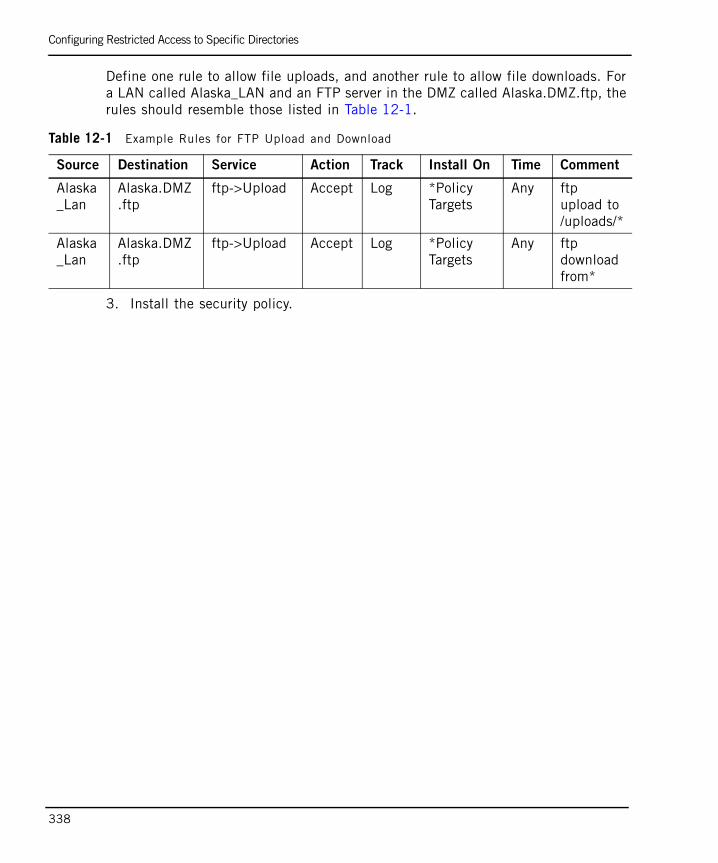
Configuring Restricted Access to Specific Directories
338
Define one rule to allow file uploads, and another rule to allow file downloads. For a LAN called Alaska_LAN and an FTP server in the DMZ called Alaska.DMZ.ftp, the rules should resemble those listed in Table 12-1.
3. Install the security policy.
Table 12-1 Example Rules for FTP Upload and Download
Source Destination Service Action Track Install On Time Comment
Alaska_Lan
Alaska.DMZ.ftp
ftp->Upload Accept Log *Policy Targets
Any ftp upload to /uploads/*
Alaska_Lan
Alaska.DMZ.ftp
ftp->Upload Accept Log *Policy Targets
Any ftp download from*

339
Chapter 13Content Security
In This Chapter
The Need for Content Security page 340
Check Point Solution for Content Security page 341
Configuring Content Security page 352
Advanced CVP Configuration: CVP Chaining and Load Sharing page 361
The Need for Content Security
340
The Need for Content SecurityProtecting corporate resources is a major concern for most businesses. Blocking undesirable content is an important part of a corporate security policy for a variety of reasons, including::
• Computer viruses, Trojans and ActiveX components containing malicious code can bring down entire networks.
• Viewing undesirable web content wastes time and resources.
Access control firewalls prevent unauthorized traffic from passing through the gateway. However, hackers also attempt to misuse allowed traffic and services. Some of the most serious threats in today's Internet environment come from attacks that attempt to exploit the application layer. Access control devices cannot easily detect malicious attacks aimed at these services.
Check Point Solution for Content Security
Chapter 13 Content Security 341
Check Point Solution for Content SecurityIn This Section
Introduction to Content SecurityVPN-1 provides Content Security by integrating with best-of-breed, OPSEC-certified applications that are complement with VPN-1 Content Security capabilities. OPSEC applications enable organizations to select content screening applications that best meet their needs, while managing Content Security centrally. These applications:
• Protect against network viruses, by scanning data and URLs to prevent viruses, malicious Java and ActiveX components, and other malicious content from entering your organization.
• Prevent users from browsing to undesirable web sites, by filtering URLs.
• Provide auditing capabilities and detailed reports.
For a listing of OPSEC Content Security solutions, refer to: http://www.opsec.com/solutions/sec_content_security.html.
Content security applications, like virus scanners, inspect the content of individual packets for specific services.
The Content Vectoring Protocol (CVP) is an API specification developed by Check Point used for integration with anti-virus servers. This API defines an asynchronous interface to server applications that validate file content. An important feature of CVP is scanning files for viruses or harmful applets as they pass through firewalls. CVP defines a client/server relationship that enables different VPN-1 gateways to share a common content validation server.
The URL Filtering protocol (UFP) blocks user access to forbidden web sites, allowing administrators to define undesirable or inappropriate types of web sites. No configuration is required at the client machine. UFP is useful for companies that wish to avoid a loss of employee productivity.
Introduction to Content Security page 341
Security Servers page 342
Deploying OPSEC Servers page 343
CVP Servers for Anti-Virus and Malicious Content Protection page 344
Using URL Filtering to Limit Web Surfers page 348
The TCP Security Server page 351
Check Point Solution for Content Security
342
In Service Provider environments, it can be offered as an add-on to Internet services, where it may be used for parental restriction of child web surfing or on behalf of businesses that have an inherent distrust of Internet content.
Security ServersSecurity servers are Check Point processes that are integrated into VPN-1. They are user mode processes that provide content security for:
• HTTP
• FTP
• SMTP
There is also a generic TCP Security server. Security servers employ many ways of enforcing Content Security, including, checking whether the connections for these protocols are well formed, stripping script tags for HTTP, email address translation for SMTP, and file name matching for FTP.
In addition to Content Security, Security servers also perform authentication. For additional information on the authentication functions of the Security servers, refer to “Authentication” on page 59.
How a Security Server Mediates a ConnectionFigure 13-1 shows how the Security servers mediate a connection. The HTTP Security server is used as an example, but the method is the same for all Security servers.
When a packet is matched to a rule that contains a resource, the Inspection Module diverts or “folds” a connection to a Security server. The Security server performs the Application Security checks, and, if necessary, diverts the connection to a Content Vectoring Protocol (CVP) server application or a URL Filtering (UFP) server application. The Security server then returns the connection to the Inspection Module, which opens a second connection that is sent on the destination HTTP server.
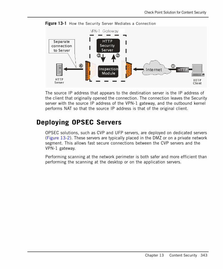
Check Point Solution for Content Security
Chapter 13 Content Security 343
Figure 13-1 How the Security Server Mediates a Connection
The source IP address that appears to the destination server is the IP address of the client that originally opened the connection. The connection leaves the Security server with the source IP address of the VPN-1 gateway, and the outbound kernel performs NAT so that the source IP address is that of the original client.
Deploying OPSEC ServersOPSEC solutions, such as CVP and UFP servers, are deployed on dedicated servers (Figure 13-2). These servers are typically placed in the DMZ or on a private network segment. This allows fast secure connections between the CVP servers and the VPN-1 gateway.
Performing scanning at the network perimeter is both safer and more efficient than performing the scanning at the desktop or on the application servers.
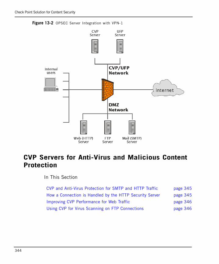
Check Point Solution for Content Security
344
Figure 13-2 OPSEC Server Integration with VPN-1
CVP Servers for Anti-Virus and Malicious Content Protection
In This Section
CVP and Anti-Virus Protection for SMTP and HTTP Traffic page 345
How a Connection is Handled by the HTTP Security Server page 345
Improving CVP Performance for Web Traffic page 346
Using CVP for Virus Scanning on FTP Connections page 346
Check Point Solution for Content Security
Chapter 13 Content Security 345
CVP and Anti-Virus Protection for SMTP and HTTP TrafficTo perform virus scanning, the HTTP or SMTP security server transfers packets from the VPN-1 gateway to another server running an OPSEC certified virus scanner. This method uses the Content Vectoring Protocol (CVP) to transfer packets to and from an OPSEC virus scanning server.
The virus scanning CVP server determines if there is a virus. If it finds a virus it can either:
• Return the file to the VPN-1 gateway with the offending content removed (if the CVP server is configured to modify content), or
• Drop the file (if the CVP server is not allowed to modify content).
CVP uses TCP port 18181, by default.
How a Connection is Handled by the HTTP Security ServerThis section describes how the HTTP Security server handles a connection where CVP checking is performed. The VPN-1 gateway that runs the HTTP Security server acts as a proxy, and so is not an active participant in the connection.
The connection request/response process without a CVP server is:
1. HTTP client to HTTP server (request)
2. HTTP server to HTTP client (response)
The data that needs to be checked is carried in the response that comes from the Web server. Therefore, when a CVP server is used, the response is always checked. In that case, the connection request/response process is:
1. HTTP client to HTTP server (request)
2. HTTP server to CVP server (response)
3. CVP server to HTTP client (response)
Check Point Solution for Content Security
346
Normally, only HTTP responses, which come from the Web server, are sent to the CVP server for checking. However, you also may wish to protect against undesirable content in the HTTP request, for example, when inspecting peer-to-peer connections. In this case, the connection request/response process is:
1. HTTP client to CVP server (request)
2. CVP server to HTTP server (request)
3. HTTP server to CVP server (response)
4. CVP server to HTTP client (response)
The HTTP Security server can be configured to send HTTP headers to the CVP server, as well as the HTTP message data.
Improving CVP Performance for Web TrafficHTTP Security server performance can be significantly improved by ensuring that safe traffic is not sent to the CVP server. This reducess the number of connections opened with the CVP server. Nonetheless, sending all content for CVP checking provides better protection.
VPN-1 considers non-executable picture and video files to be safe because they do not normally contain viruses.
The HTTP Security server identifies safe content by actually examining the contents of a file. It does not rely on examining the URL (for file extensions such as *.GIF) nor does it rely on checking the MIME type (such as image/gif) in the server response.
For configuration details, refer to “Configuring CVP Checking for Web Traffic with Improved Performance” on page 356.
Using CVP for Virus Scanning on FTP Connections Virus scanning on FTP connections can be performed by transferring the file to a third-party anti-virus application using the CVP protocol.
Figure 13-3 illustrates how VPN-1 implements CVP for virus checking on an FTP connection.
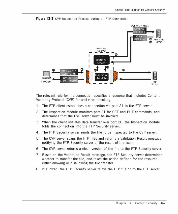
Check Point Solution for Content Security
Chapter 13 Content Security 347
Figure 13-3 CVP Inspection Process during an FTP Connection
The relevant rule for the connection specifies a resource that includes Content Vectoring Protocol (CVP) for anti-virus checking.
1. The FTP client establishes a connection via port 21 to the FTP server.
2. The Inspection Module monitors port 21 for GET and PUT commands, and determines that the CVP server must be invoked.
3. When the client initiates data transfer over port 20, the Inspection Module folds the connection into the FTP Security server.
4. The FTP Security server sends the file to be inspected to the CVP server.
5. The CVP server scans the FTP files and returns a Validation Result message, notifying the FTP Security server of the result of the scan.
6. The CVP server returns a clean version of the file to the FTP Security server.
7. Based on the Validation Result message, the FTP Security server determines whether to transfer the file, and takes the action defined for the resource, either allowing or disallowing the file transfer.
8. If allowed, the FTP Security server relays the FTP file on to the FTP server.

Check Point Solution for Content Security
348
Using URL Filtering to Limit Web Surfers
In This Section
Understanding URL FilteringThe security administrator can prevent access to specific destinations on the Internet, allow access only to appropriate web pages, and make it impossible to access particular web sites, or download certain file types.
This is done using third-party, OPSEC-certified URL SmartCenter applications. The security administrator can define a corporate security policy that includes URL screening to block undesirable web pages and to record the types of URLs accessed for internal analysis and reporting needs.
A URL Filtering Protocol (UFP) serverto maintains a list of URLs and their categories. When a user requests a URL, VPN-1 checks that URL against a UFP server, which returns the category under which the URL falls. In SmartDashboard, permitted categories can be selected. Access to the web page is allowed if the URL is in a permitted category.
By default, UFP uses TCP port 18182.
VPN-1 can integrate with OPSEC-certified solutions in two ways:
• Enhanced UFP Performance mode (called Enhanced UFP Performance in the URI Resource) uses VPN-1 kernel inspection together with a dedicated UFP daemon (aufpd). However, in this mode, it is not possible to use CVP and UFP checking on the same connection.
• The ordinary UFP checking mode uses the VPN-1 HTTP Security server to mediate UFP connections. This can add significantly to the response time experienced by clients that browse web sites, in comparison to the Enhanced UFP Performance mode.
Understanding URL Filtering page 348
URL Filtering Using the HTTP Security Server page 349
Enhanced UFP Performance Mode page 350
Choosing the URL Filtering Mode page 351
Note - A basic URL filtering capability is built in to VPN-1. It can be used to block a specific list of URLs without a UFP server. For details, refer to “Basic URL Filtering” on page 380.
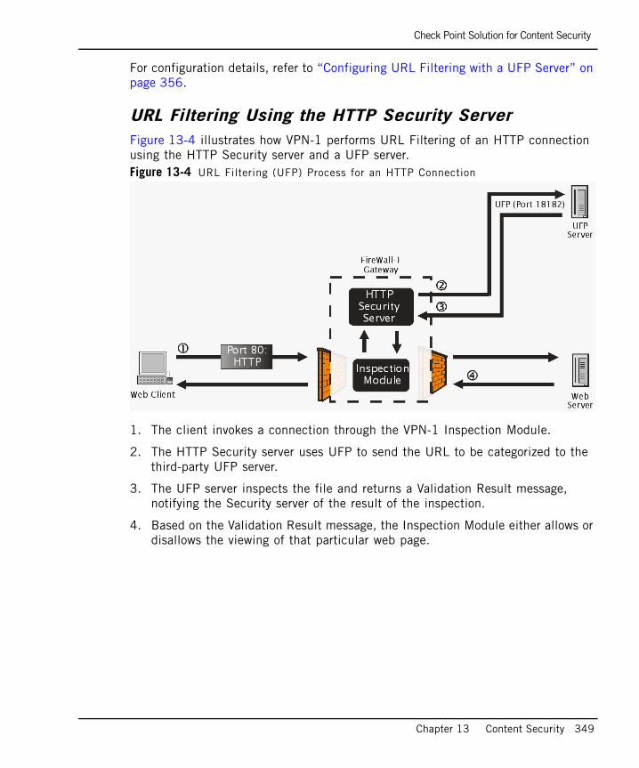
Check Point Solution for Content Security
Chapter 13 Content Security 349
For configuration details, refer to “Configuring URL Filtering with a UFP Server” on page 356.
URL Filtering Using the HTTP Security Server Figure 13-4 illustrates how VPN-1 performs URL Filtering of an HTTP connection using the HTTP Security server and a UFP server.Figure 13-4 URL Filtering (UFP) Process for an HTTP Connection
1. The client invokes a connection through the VPN-1 Inspection Module.
2. The HTTP Security server uses UFP to send the URL to be categorized to the third-party UFP server.
3. The UFP server inspects the file and returns a Validation Result message, notifying the Security server of the result of the inspection.
4. Based on the Validation Result message, the Inspection Module either allows or disallows the viewing of that particular web page.

Check Point Solution for Content Security
350
Enhanced UFP Performance Mode Figure 13-5 illustrates how enhanced URL Filtering (UFP) performance of an HTTP connection works.Figure 13-5 Enhanced URL Filtering (UFP) Process, Using Kernel Inspection
1. The web client invokes a connection through the VPN-1 Inspection Module.
2. The kernel Inspection Module puts up a barrier that prevents the web clients receiving a response from the web server before a confirmation is received from the UFP server.
3. HTTP requests destined for the web server go through VPN-1 uninterrupted.
4. At the same time as step 3, the Inspection Module extracts the URL, and the AUFPD daemon establishes a UFP session with the UFP server to categorize the URL.
5. Based on the Validation Result message, AUFPD tells the Inspection Module whether or not to block the URL.
6. If the URL is permitted, the barrier is removed, and the HTTP response from the web server is allowed through VPN-1.
7. If the URL is blocked, the HTTP response is rejected.
Check Point Solution for Content Security
Chapter 13 Content Security 351
Choosing the URL Filtering Mode“Enhanced UFP Performance Mode” and “URL Filtering Using the HTTP Security Server” are different ways of performing UFP Filtering. When deciding the method to employ, you must balance performance against security.
When the Enhanced UFP Performance mode is used, users browsing web sites experience significantly improved response times, as compared to UFP checking using the VPN-1 HTTP Security server. However, in this mode (called Enhanced UFP Performance in the URI Resource), it is not possible to use CVP and UFP checking on the same connection.
The TCP Security ServerMalicious content can potentially be carried in any TCP service, not only SMTP, HTTP and FTP.
The TCP Security server is used to perform CVP or UFP Content Security by a third-party, OPSEC-compliant application, on any TCP Service.
For configuration details, refer to“Performing CVP or UFP Inspection on any TCP Service” on page 360.
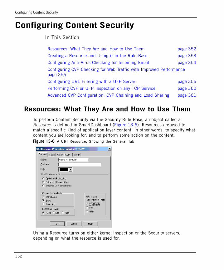
Configuring Content Security
352
Configuring Content SecurityIn This Section
Resources: What They Are and How to Use ThemTo perform Content Security via the Security Rule Base, an object called a Resource is defined in SmartDashboard (Figure 13-6). Resources are used to match a specific kind of application layer content, in other words, to specify what content you are looking for, and to perform some action on the content. Figure 13-6 A URI Resource, Showing the General Tab
Using a Resource turns on either kernel inspection or the Security servers, depending on what the resource is used for.
Resources: What They Are and How to Use Them page 352
Creating a Resource and Using it in the Rule Base page 353
Configuring Anti-Virus Checking for Incoming Email page 354
Configuring CVP Checking for Web Traffic with Improved Performance page 356
Configuring URL Filtering with a UFP Server page 356
Performing CVP or UFP Inspection on any TCP Service page 360
Advanced CVP Configuration: CVP Chaining and Load Sharing page 361
Configuring Content Security
Chapter 13 Content Security 353
For instance, a rule can be created that will drop the connection and generate an alert if there are GETs or PUTs in an FTP transfer or if a specifically named file is part of the transfer. Another rule can drop email addresses or attachments while allowing the rest of the content through.
To specify the content you are looking for, regular expressions and wildcards can be used in the Resource.
The Resource is triggered when a rule includes the Resource, and a packet matching that rule is encountered. A Resource is applied per Service. If a connection matches the source and destination of the rule and the match parameters of the Resource, then both the action in the rule and the action in the Resource are applied.
Creating a Resource and Using it in the Rule Base1. To create a resource, select the Resources tab in the objects tree. Select the
Resource Type, right-click, select a resource type, such as New URI... or New SMTP....
2. Define the resource parameters in the General tab, and in the other tabs as required.
3. To use a service with a resource in a rule, right-click in the Service column of the rule, right-click, and select Add with Resource.... In the Service with Resource window, select the service, and then select the Resource that will operate on the service. Click OK.
If a connection matches the source and destination of the rule and the match parameters of the Resource, then both the action in the rule and the action in the Resource are applied.
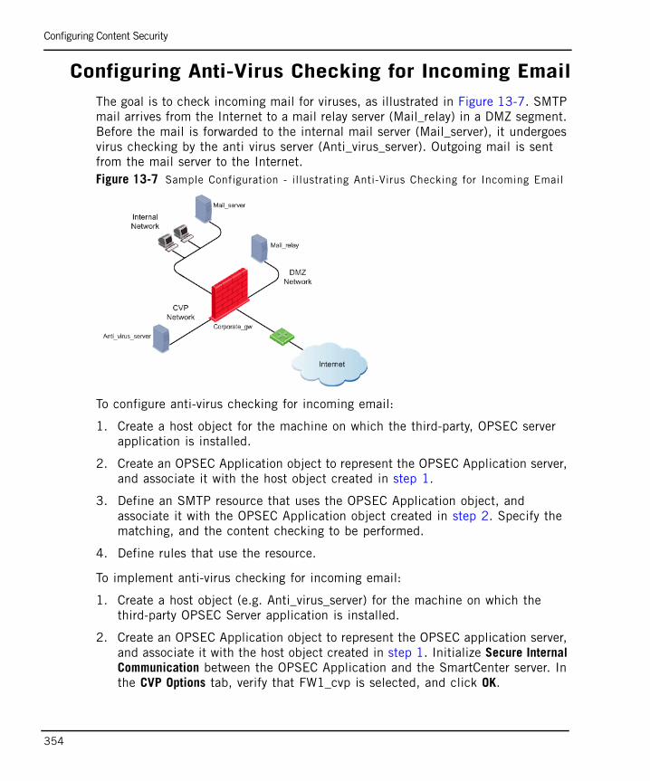
Configuring Content Security
354
Configuring Anti-Virus Checking for Incoming EmailThe goal is to check incoming mail for viruses, as illustrated in Figure 13-7. SMTP mail arrives from the Internet to a mail relay server (Mail_relay) in a DMZ segment. Before the mail is forwarded to the internal mail server (Mail_server), it undergoes virus checking by the anti virus server (Anti_virus_server). Outgoing mail is sent from the mail server to the Internet.Figure 13-7 Sample Configuration - illustrating Anti-Virus Checking for Incoming Email
To configure anti-virus checking for incoming email:
1. Create a host object for the machine on which the third-party, OPSEC server application is installed.
2. Create an OPSEC Application object to represent the OPSEC Application server, and associate it with the host object created in step 1.
3. Define an SMTP resource that uses the OPSEC Application object, and associate it with the OPSEC Application object created in step 2. Specify the matching, and the content checking to be performed.
4. Define rules that use the resource.
To implement anti-virus checking for incoming email:
1. Create a host object (e.g. Anti_virus_server) for the machine on which the third-party OPSEC Server application is installed.
2. Create an OPSEC Application object to represent the OPSEC application server, and associate it with the host object created in step 1. Initialize Secure Internal Communication between the OPSEC Application and the SmartCenter server. In the CVP Options tab, verify that FW1_cvp is selected, and click OK.
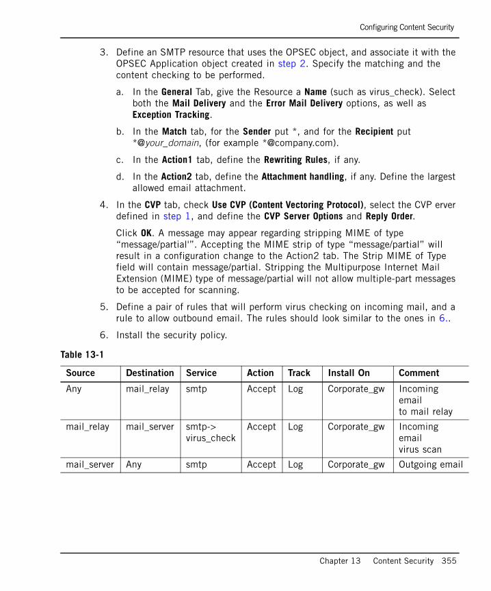
Configuring Content Security
Chapter 13 Content Security 355
3. Define an SMTP resource that uses the OPSEC object, and associate it with the OPSEC Application object created in step 2. Specify the matching and the content checking to be performed.
a. In the General Tab, give the Resource a Name (such as virus_check). Select both the Mail Delivery and the Error Mail Delivery options, as well as Exception Tracking.
b. In the Match tab, for the Sender put *, and for the Recipient put *@your_domain, (for example *@company.com).
c. In the Action1 tab, define the Rewriting Rules, if any.
d. In the Action2 tab, define the Attachment handling, if any. Define the largest allowed email attachment.
4. In the CVP tab, check Use CVP (Content Vectoring Protocol), select the CVP erver defined in step 1, and define the CVP Server Options and Reply Order.
Click OK. A message may appear regarding stripping MIME of type “message/partial'”. Accepting the MIME strip of type “message/partial” will result in a configuration change to the Action2 tab. The Strip MIME of Type field will contain message/partial. Stripping the Multipurpose Internet Mail Extension (MIME) type of message/partial will not allow multiple-part messages to be accepted for scanning.
5. Define a pair of rules that will perform virus checking on incoming mail, and a rule to allow outbound email. The rules should look similar to the ones in 6..
6. Install the security policy.
Table 13-1
Source Destination Service Action Track Install On Comment
Any mail_relay smtp Accept Log Corporate_gw Incoming emailto mail relay
mail_relay mail_server smtp->virus_check
Accept Log Corporate_gw Incoming emailvirus scan
mail_server Any smtp Accept Log Corporate_gw Outgoing email
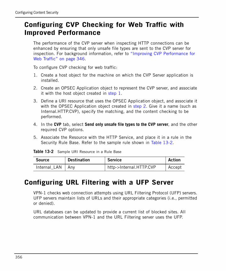
Configuring Content Security
356
Configuring CVP Checking for Web Traffic with Improved Performance
The performance of the CVP server when inspecting HTTP connections can be enhanced by ensuring that only unsafe file types are sent to the CVP server for inspection. For background information, refer to “Improving CVP Performance for Web Traffic” on page 346.
To configure CVP checking for web traffic:
1. Create a host object for the machine on which the CVP Server application is installed.
2. Create an OPSEC Application object to represent the CVP server, and associate it with the host object created in step 1.
3. Define a URI resource that uses the OPSEC Application object, and associate it with the OPSEC Application object created in step 2. Give it a name (such as Internal.HTTP.CVP), specify the matching, and the content checking to be performed.
4. In the CVP tab, select Send only unsafe file types to the CVP server, and the other required CVP options.
5. Associate the Resource with the HTTP Service, and place it in a rule in the Security Rule Base. Refer to the sample rule shown in Table 13-2.
Configuring URL Filtering with a UFP ServerVPN-1 checks web connection attempts using URL Filtering Protocol (UFP) servers. UFP servers maintain lists of URLs and their appropriate categories (i.e., permitted or denied).
URL databases can be updated to provide a current list of blocked sites. All communication between VPN-1 and the URL Filtering server uses the UFP.
Table 13-2 Sample URI Resource in a Rule Base
Source Destination Service Action
Internal_LAN Any http->Internal.HTTP.CVP Accept
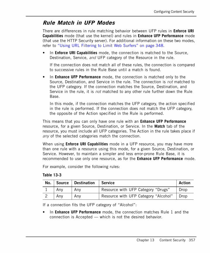
Configuring Content Security
Chapter 13 Content Security 357
Rule Match in UFP ModesThere are differences in rule matching behavior between UFP rules in Enforce URI Capabilities mode (that use the kernel) and rules in Enhance UFP Performance mode (that use the HTTP Security server). For additional information on these two modes, refer to “Using URL Filtering to Limit Web Surfers” on page 348.
• In Enforce URI Capabilities mode, the connection is matched to the Source, Destination, Service, and UFP category of the Resource in the rule.
If the connection does not match all of these rules, the connection is compared to successive rules in the Rule Base until a match is found.
• In Enhance UFP Performance mode, the connection is matched only to the Source, Destination, and Service in the rule. The connection is not matched to the UFP category. If the connection matches the Source, Destination, and Service in the rule, it is not matched to any other rule further down the Rule Base.
In this mode, if the connection matches the UFP category, the action specified in the rule is performed. If the connection does not match the UFP category, the opposite of the Action specified in the Rule is performed.
This means that you can only have one rule with an Enhance UFP Performance resource, for a given Source, Destination, or Service. In the Match tab of the resource, you must include all UFP categories. The Action in the rule takes place if any of the selected categories match the connection.
When using Enforce URI Capabilities mode in a UFP resource, you may have more than one rule with a resource using this mode, for a given Source, Destination, or Service. However, to maintain a simpler and less error-prone Rule Base, it is recommended to use only one resource, as for the Enhance UFP Performance mode.
For example, consider the following rules:
If a connection fits the UFP category of “Alcohol”:
• In Enhance UFP Performance mode, the connection matches Rule 1 and the connection is Accepted — which is not the desired behavior.
Table 13-3
No. Source Destination Service Action
1 Any Any Resource with UFP Category “Drugs” Drop
2 Any Any Resource with UFP Category “Alcohol” Drop
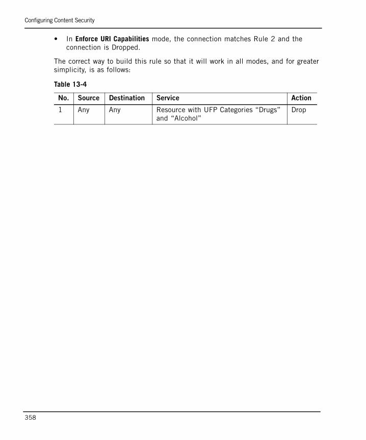
Configuring Content Security
358
• In Enforce URI Capabilities mode, the connection matches Rule 2 and the connection is Dropped.
The correct way to build this rule so that it will work in all modes, and for greater simplicity, is as follows:
Table 13-4
No. Source Destination Service Action
1 Any Any Resource with UFP Categories “Drugs” and “Alcohol”
Drop
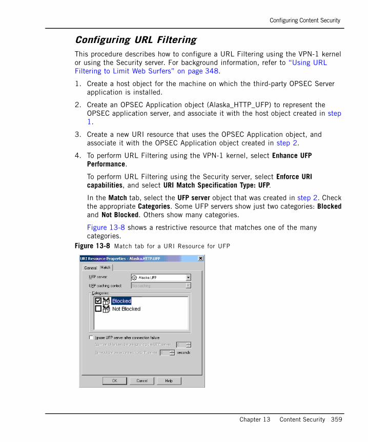
Configuring Content Security
Chapter 13 Content Security 359
Configuring URL Filtering This procedure describes how to configure a URL Filtering using the VPN-1 kernel or using the Security server. For background information, refer to “Using URL Filtering to Limit Web Surfers” on page 348.
1. Create a host object for the machine on which the third-party OPSEC Server application is installed.
2. Create an OPSEC Application object (Alaska_HTTP_UFP) to represent the OPSEC application server, and associate it with the host object created in step 1.
3. Create a new URI resource that uses the OPSEC Application object, and associate it with the OPSEC Application object created in step 2.
4. To perform URL Filtering using the VPN-1 kernel, select Enhance UFP Performance.
To perform URL Filtering using the Security server, select Enforce URI capabilities, and select URI Match Specification Type: UFP.
In the Match tab, select the UFP server object that was created in step 2. Check the appropriate Categories. Some UFP servers show just two categories: Blocked and Not Blocked. Others show many categories.
Figure 13-8 shows a restrictive resource that matches one of the many categories.
Figure 13-8 Match tab for a URI Resource for UFP
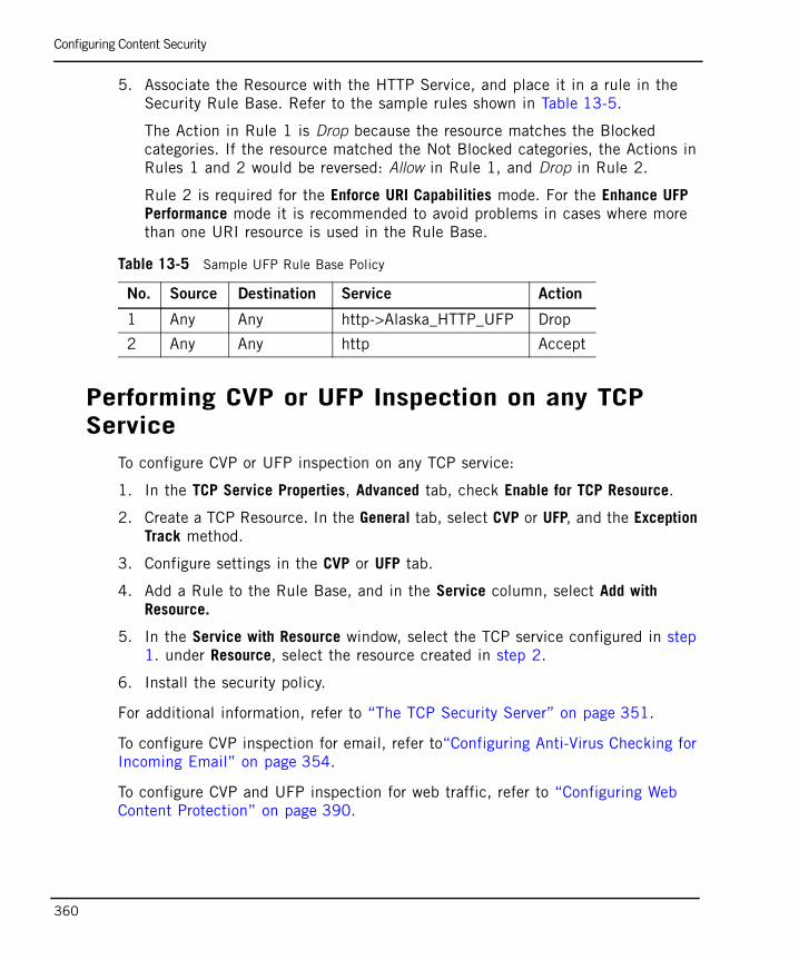
Configuring Content Security
360
5. Associate the Resource with the HTTP Service, and place it in a rule in the Security Rule Base. Refer to the sample rules shown in Table 13-5.
The Action in Rule 1 is Drop because the resource matches the Blocked categories. If the resource matched the Not Blocked categories, the Actions in Rules 1 and 2 would be reversed: Allow in Rule 1, and Drop in Rule 2.
Rule 2 is required for the Enforce URI Capabilities mode. For the Enhance UFP Performance mode it is recommended to avoid problems in cases where more than one URI resource is used in the Rule Base.
Performing CVP or UFP Inspection on any TCP Service
To configure CVP or UFP inspection on any TCP service:
1. In the TCP Service Properties, Advanced tab, check Enable for TCP Resource.
2. Create a TCP Resource. In the General tab, select CVP or UFP, and the Exception Track method.
3. Configure settings in the CVP or UFP tab.
4. Add a Rule to the Rule Base, and in the Service column, select Add with Resource.
5. In the Service with Resource window, select the TCP service configured in step 1. under Resource, select the resource created in step 2.
6. Install the security policy.
For additional information, refer to “The TCP Security Server” on page 351.
To configure CVP inspection for email, refer to“Configuring Anti-Virus Checking for Incoming Email” on page 354.
To configure CVP and UFP inspection for web traffic, refer to “Configuring Web Content Protection” on page 390.
Table 13-5 Sample UFP Rule Base Policy
No. Source Destination Service Action
1 Any Any http->Alaska_HTTP_UFP Drop
2 Any Any http Accept
Advanced CVP Configuration: CVP Chaining and Load Sharing
Chapter 13 Content Security 361
Advanced CVP Configuration: CVP Chaining and Load Sharing
In This Section
Introduction to CVP Chaining and Load SharingTraffic that crosses the VPN-1 gateway can be checked using CVP servers. CVP checking is available for Web, Mail, FTP and TCP traffic. For detailed explanations, see:
• “CVP and Anti-Virus Protection for SMTP and HTTP Traffic” on page 345.
• “Using CVP for Virus Scanning on FTP Connections” on page 346.
It is possible to chain CVP servers in order to combine functionality, and to perform load sharing between CVP servers, in order to speed up CVP checking.
CVP ChainingCVP servers can be chained for the purpose of combining functionality. Chaining is useful when each of the CVP servers performs a different task, such as scanning for viruses, or blocking large email attachments. In the configuration shown in Figure 13-9, the VPN-1 Security server invokes the first, second, and third CVP servers in turn.
Introduction to CVP Chaining and Load Sharing page 361
CVP Chaining page 361
CVP Load Sharing page 363
Combining CVP Chaining and Load Sharing page 364
Configuring CVP Chaining and Load Sharing page 364
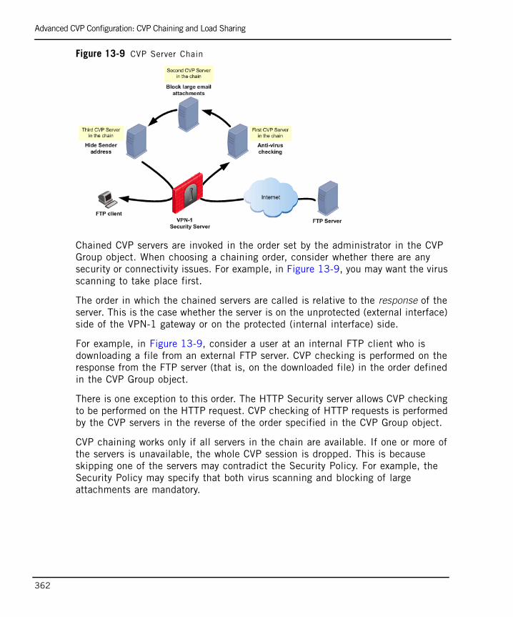
Advanced CVP Configuration: CVP Chaining and Load Sharing
362
Figure 13-9 CVP Server Chain
Chained CVP servers are invoked in the order set by the administrator in the CVP Group object. When choosing a chaining order, consider whether there are any security or connectivity issues. For example, in Figure 13-9, you may want the virus scanning to take place first.
The order in which the chained servers are called is relative to the response of the server. This is the case whether the server is on the unprotected (external interface) side of the VPN-1 gateway or on the protected (internal interface) side.
For example, in Figure 13-9, consider a user at an internal FTP client who is downloading a file from an external FTP server. CVP checking is performed on the response from the FTP server (that is, on the downloaded file) in the order defined in the CVP Group object.
There is one exception to this order. The HTTP Security server allows CVP checking to be performed on the HTTP request. CVP checking of HTTP requests is performed by the CVP servers in the reverse of the order specified in the CVP Group object.
CVP chaining works only if all servers in the chain are available. If one or more of the servers is unavailable, the whole CVP session is dropped. This is because skipping one of the servers may contradict the Security Policy. For example, the Security Policy may specify that both virus scanning and blocking of large attachments are mandatory.
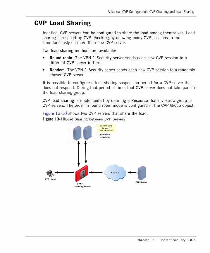
Advanced CVP Configuration: CVP Chaining and Load Sharing
Chapter 13 Content Security 363
CVP Load SharingIdentical CVP servers can be configured to share the load among themselves. Load sharing can speed up CVP checking by allowing many CVP sessions to run simultaneously on more than one CVP server.
Two load-sharing methods are available:
• Round robin: The VPN-1 Security server sends each new CVP session to a different CVP server in turn.
• Random: The VPN-1 Security server sends each new CVP session to a randomly chosen CVP server.
It is possible to configure a load-sharing suspension period for a CVP server that does not respond. During that period of time, that CVP server does not take part in the load-sharing group.
CVP load sharing is implemented by defining a Resource that invokes a group of CVP servers. The order in round robin mode is configured in the CVP Group object.
Figure 13-10 shows two CVP servers that share the load.Figure 13-10Load Sharing between CVP Servers
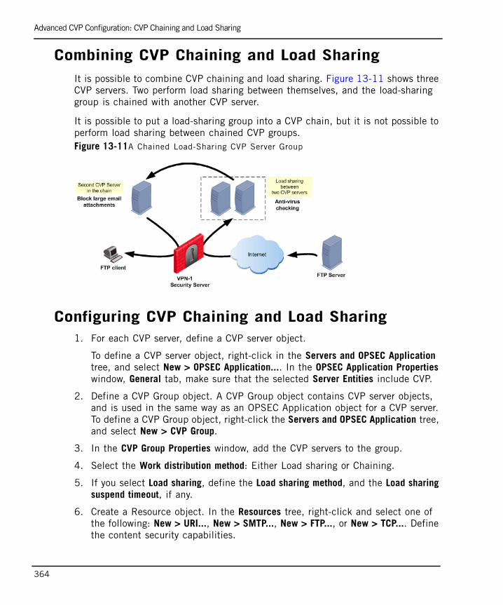
Advanced CVP Configuration: CVP Chaining and Load Sharing
364
Combining CVP Chaining and Load SharingIt is possible to combine CVP chaining and load sharing. Figure 13-11 shows three CVP servers. Two perform load sharing between themselves, and the load-sharing group is chained with another CVP server.
It is possible to put a load-sharing group into a CVP chain, but it is not possible to perform load sharing between chained CVP groups.Figure 13-11A Chained Load-Sharing CVP Server Group
Configuring CVP Chaining and Load Sharing1. For each CVP server, define a CVP server object.
To define a CVP server object, right-click in the Servers and OPSEC Application tree, and select New > OPSEC Application.... In the OPSEC Application Properties window, General tab, make sure that the selected Server Entities include CVP.
2. Define a CVP Group object. A CVP Group object contains CVP server objects, and is used in the same way as an OPSEC Application object for a CVP server. To define a CVP Group object, right-click the Servers and OPSEC Application tree, and select New > CVP Group.
3. In the CVP Group Properties window, add the CVP servers to the group.
4. Select the Work distribution method: Either Load sharing or Chaining.
5. If you select Load sharing, define the Load sharing method, and the Load sharing suspend timeout, if any.
6. Create a Resource object. In the Resources tree, right-click and select one of the following: New > URI..., New > SMTP..., New > FTP..., or New > TCP.... Define the content security capabilities.
Advanced CVP Configuration: CVP Chaining and Load Sharing
Chapter 13 Content Security 365
7. In the CVP Server field in the CVP tab of the Resource object, select the CVP Group defined in step 2.
8. In the Security Rule Base, define a rule that uses the Resource.
9. Save and install the security policy.

Advanced CVP Configuration: CVP Chaining and Load Sharing
366
367
Chapter 14Services with Application Intelligence
In This Chapter
DCE-RPC page 368
SSLv3 Service page 369
SSHv2 Service page 369
FTP_BASIC Protocol Type page 369
Domain_UDP Service page 370
Point-to-Point Tunneling Protocol (PPTP) page 371
Blocking Visitor Mode (TCPT) page 373
Introduction to Services with Application Intelligence
368
Introduction to Services with Application Intelligence
There are a number of TCP services for which VPN-1 can perform content inspection, in addition to checking port numbers.
Services that support content inspection are those services having a defined Protocol Type in the TCP Service Properties>Advanced window, either nbsession or Microsoft-DS together with the configured Resource.
DCE-RPCDCE-RPC (Distributed Computing Environment- Remote Procedure Call) is a technology that calls a procedure on a remote machine. Unlike other services that are associated with a specific TCP or UDP port, DCE-RPC uses dynamically assigned port numbers assigned by the Endpoint Mapper.
DCE-RPC uses the Endpoint Mapper mechanism for the purpose of dynamically assigning a port number to specific applications. A client that wishes to connect to a DCE-RPC application typically connects to TCP135 (the default RPC Endpoint Mapper port) and provides the Endpoint Mapper with a UUID number interface. In return, the Endpoint Mapper provides the client with a port to which the client can connect.
SmartView Tracker logs UUID interfaces, making it possible to identify non-common UUID interfaces. UUID interfaces can be used to enforce security rules.
Warning - Do not delete or change the protocol type of the service objects that perform content inspection. If the service is altered in this way, the content inspection may not work.
SSLv3 Service
Chapter 14 Services with Application Intelligence 369
SSLv3 ServiceTo prevent security problems associated with earlier versions of SSL, it is possible to verify that SSL client connections are using version 3 or higher of the SSL protocol. SSLv3 enforcement is enabled using the ssl_v3 service.
If the ssl_v3 service is used in a rule, and an SSLv2 connection is attempted, the connection is rejected. Many Internet browsers use SSLv2. To allow their connections to pass through VPN-1, use the HTTPS service in the Rule Base.
SSHv2 ServiceTo prevent security problems associated with earlier versions of SSH, it is possible to verify that SSH connections are using version 2 or higher of the protocol. SSHv2 enforcement is enabled using the ssh_version_2 service.
If the SSHv2 service is used in a rule, SSHv1 connections are dropped.
FTP_BASIC Protocol TypeFTP_BASIC is a new protocol type. This protocol enforces a reduced set of the FTP security checks performed by the regular FTP protocol type. Using FTP_BASIC eliminates known connectivity problems with FTP implementations that are not fully RFC compliant. The following checks are NOT enforced by FTP_BASIC, and are enforced by the FTP protocol type:
• Every packet must be terminated with a newline character, so that the PORT command is not split across packets. This protects against the FTP Bounce attack.
• Data connections to or from well-known ports are not allowed, to prevent the FTP data connection being used to access some other service.
• Bidirectional traffic on the data connection is not allowed, as it can be used improperly.
Domain_UDP Service
370
Domain_UDP ServiceThe Domain_UDP service provides access control for DNS.
• DNS performance when using this service has been improved. Many DNS connections are for queries which comprise one request and one reply packet. VPN-1 normally maintains virtual DNS connections for the period of the UDP timeout. DNS verification speed can be improved by telling VPN-1 to delete the connection as soon as it receives the reply packet. To do this, change the property delete_on_reply (false) to true using the Database Tool.
• DNS logs are more informative. For example, the domain of the device making a DNS query is now shown in the Information column.
• DNS verification of EDNS queries is supported. This allows use of BIND. EDNS headers are allowed if they contain all zeros, other than the field that controls the packet length (maximum payload size).

Point-to-Point Tunneling Protocol (PPTP)
Chapter 14 Services with Application Intelligence 371
Point-to-Point Tunneling Protocol (PPTP)Point-to-Point Tunneling Protocol (PPTP) is a network protocol for creating Virtual Private Networks (VPNs) over the Internet. It was developed jointly by Microsoft Corporation and several remote access vendor companies.
PPTP sets up a secure client-to-client connection via a PPTP server. The connection is made up of TCP/PPTP control connections and the GRE data connections, GRE being the actual VPN tunnel.
VPN-1 secures PPTP while allowing Hide NAT as well as Static NAT for PPTP connections. VPN-1 can also enforce compliance to the PPTP protocol. If enforcement is turned on, PPTP packets are checked for compliance with RFC 2637, including message type, and packet length. In addition, if the PPTP control connection closes, the GRE tunnel is also closed.
Configuring for PPTPTo configure PPTP:
1. Define an object for the PPTP client that originates the connection, and an object for the PPTP server (not the destination client).
2. To allow PPTP connections through the VPN-1 gateway, you must define a PPTP rule in the Security Rule Base using the pptp_tcp service. In the service column, set either pptp_tcp or Any (by default the pptp_tcp Service object is set to Match for Any in the Advanced Service Properties).
3. To enforce compliance to the PPTP protocol and allow Hide NAT, turn on enforcement in SmartDefense Application Intelligence > VPN Protocols > Point to Point Tunneling Protocol. Static NAT is supported even with the enforcement turned off. SmartDefense enforcement is turned on by default for new installations. For upgrades it is turned off.
Table 14-1
Source Destination Service Action
pptp_client pptp_server TCP: pptp_tcp Accept
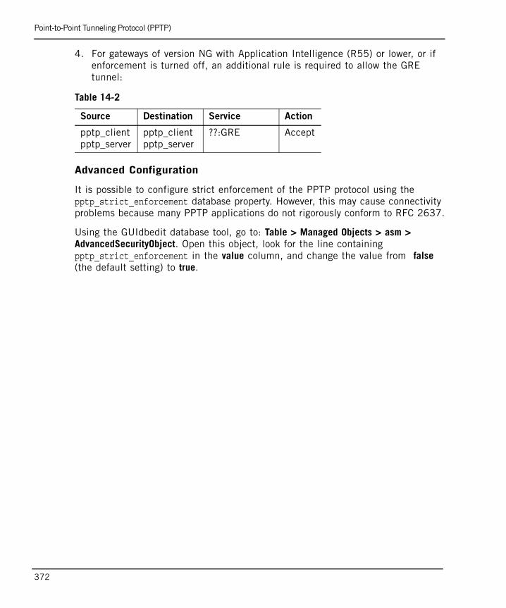
Point-to-Point Tunneling Protocol (PPTP)
372
4. For gateways of version NG with Application Intelligence (R55) or lower, or if enforcement is turned off, an additional rule is required to allow the GRE tunnel:
Advanced Configuration
It is possible to configure strict enforcement of the PPTP protocol using the pptp_strict_enforcement database property. However, this may cause connectivity problems because many PPTP applications do not rigorously conform to RFC 2637.
Using the GUIdbedit database tool, go to: Table > Managed Objects > asm > AdvancedSecurityObject. Open this object, look for the line containing pptp_strict_enforcement in the value column, and change the value from false (the default setting) to true.
Table 14-2
Source Destination Service Action
pptp_clientpptp_server
pptp_clientpptp_server
??:GRE Accept
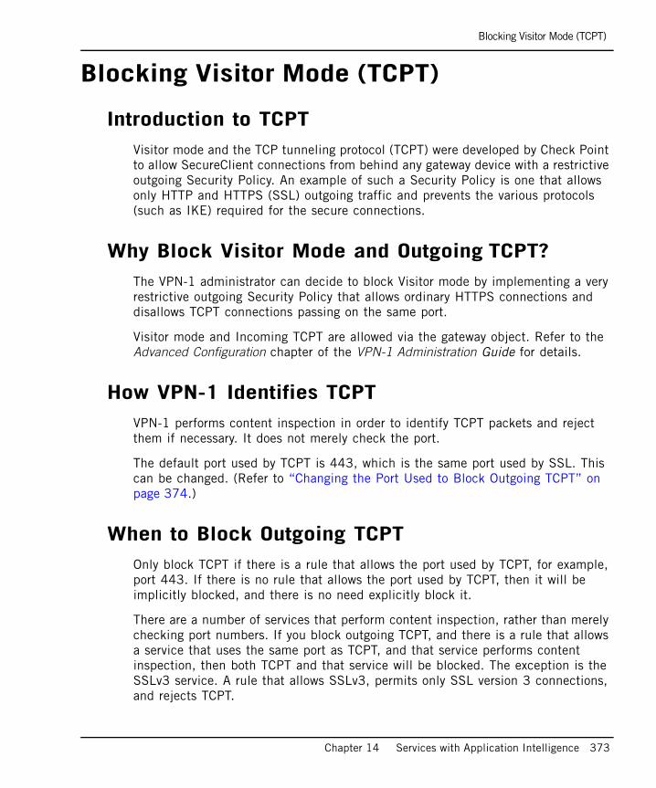
Blocking Visitor Mode (TCPT)
Chapter 14 Services with Application Intelligence 373
Blocking Visitor Mode (TCPT)
Introduction to TCPTVisitor mode and the TCP tunneling protocol (TCPT) were developed by Check Point to allow SecureClient connections from behind any gateway device with a restrictive outgoing Security Policy. An example of such a Security Policy is one that allows only HTTP and HTTPS (SSL) outgoing traffic and prevents the various protocols (such as IKE) required for the secure connections.
Why Block Visitor Mode and Outgoing TCPT?The VPN-1 administrator can decide to block Visitor mode by implementing a very restrictive outgoing Security Policy that allows ordinary HTTPS connections and disallows TCPT connections passing on the same port.
Visitor mode and Incoming TCPT are allowed via the gateway object. Refer to the Advanced Configuration chapter of the VPN-1 Administration Guide for details.
How VPN-1 Identifies TCPTVPN-1 performs content inspection in order to identify TCPT packets and reject them if necessary. It does not merely check the port.
The default port used by TCPT is 443, which is the same port used by SSL. This can be changed. (Refer to “Changing the Port Used to Block Outgoing TCPT” on page 374.)
When to Block Outgoing TCPTOnly block TCPT if there is a rule that allows the port used by TCPT, for example, port 443. If there is no rule that allows the port used by TCPT, then it will be implicitly blocked, and there is no need explicitly block it.
There are a number of services that perform content inspection, rather than merely checking port numbers. If you block outgoing TCPT, and there is a rule that allows a service that uses the same port as TCPT, and that service performs content inspection, then both TCPT and that service will be blocked. The exception is the SSLv3 service. A rule that allows SSLv3, permits only SSL version 3 connections, and rejects TCPT.
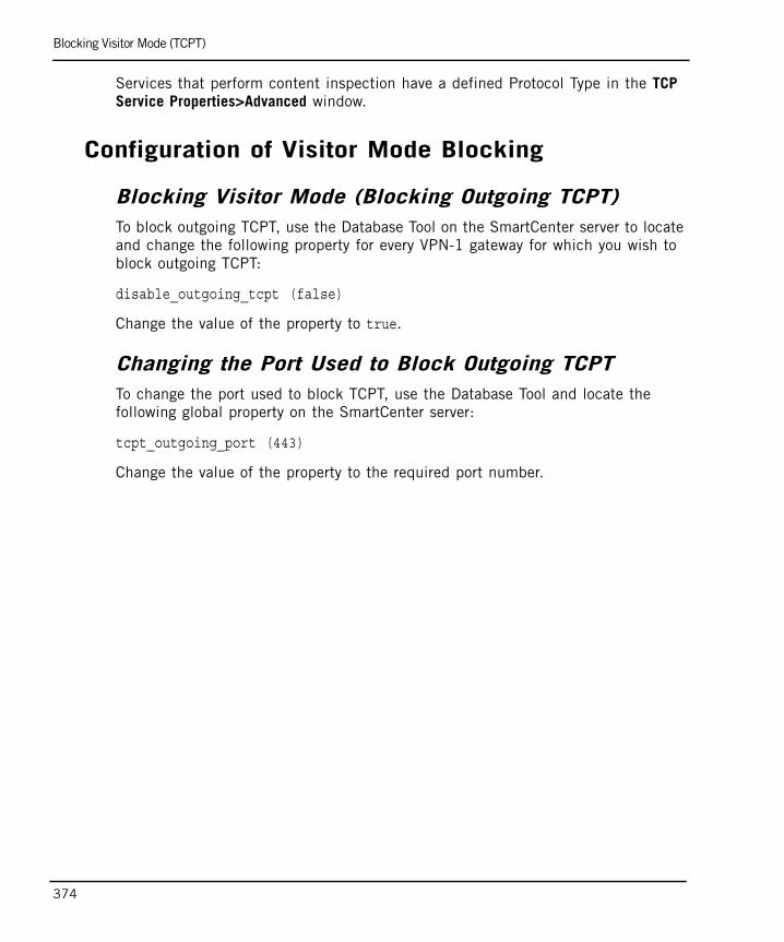
Blocking Visitor Mode (TCPT)
374
Services that perform content inspection have a defined Protocol Type in the TCP Service Properties>Advanced window.
Configuration of Visitor Mode Blocking
Blocking Visitor Mode (Blocking Outgoing TCPT)To block outgoing TCPT, use the Database Tool on the SmartCenter server to locate and change the following property for every VPN-1 gateway for which you wish to block outgoing TCPT:
disable_outgoing_tcpt (false)
Change the value of the property to true.
Changing the Port Used to Block Outgoing TCPT To change the port used to block TCPT, use the Database Tool and locate the following global property on the SmartCenter server:
tcpt_outgoing_port (443)
Change the value of the property to the required port number.
Web SecurityThis section describes the VPN-1 Web Content capabilities, as well as the Web Intelligence feature for VPN-1 that provides high performance attack protection for web servers and applications.

377
Chapter 15Web Content Protection
In This Chapter
Introduction to Web Content Protection page 378
Web Content Security via the Security Rule Base page 379
Securing XML Web Services (SOAP) page 382
Understanding HTTP Sessions, Connections and URLs page 383
Connectivity Versus Security Considerations for Web Surfers page 386
Factors Affecting HTTP Security Server Performance page 388
Configuring Web Content Protection page 390
Introduction to Web Content Protection
378
Introduction to Web Content ProtectionThis chapter discusses the following VPN-1 Web Security capabilities:
• Integrated web security capabilities configured via the Security Rule Base. These include a number of URL-based protections.
• The ability to secure XML Web Services (SOAP) on Web servers.
Web Intelligence is a VPN-1 feature that provides high performance attack protection for Web servers and applications. It provides proactive attack protection by looking for malicious code and ensuring adherence to protocols and security best practice. For details about Web Intelligence, refer to “Web Intelligence” on page 198.
Web Content Security via OPSEC partners allows network virus protection and URL filtering using best-of-breed Check Point partners. For details, refer to “Content Security” on page 339.
Web Content Security via the Security Rule Base
Chapter 15 Web Content Protection 379
Web Content Security via the Security Rule Base
In This Section
VPN-1 provides certain web security capabilities that are configured via the Security Rule Base, rather than Web Intelligence. These include a number of URL-based protections.
What is a URI Resource?Web security is implemented via the Security Rule Base by defining a SmartDashboard object called a URI Resource, and using it in the Security Rule Base. For a description of Resource objects, refer to “Resources: What They Are and How to Use Them” on page 352.
URI stands for Uniform Resource Identifier. A URI is more or less identical to the familiar URL (Uniform Resource Locator).
Filtering URLs, Schemes and Methods by Source and Destination
It is possible to block URL-based attacks, such as Code Red and Nimda, using a URI resource. Attacks from and to a specified source and destination can be blocked. HTTP methods (such as GET and POST) and schemes (such as http, ftp, and mailto) can also be blocked.
URL patterns are specified using regular expressions. The URL can be broken into filterable components using the Host, Path and Query parameters that are specified in the Match tab.
For configuration details, refer to “Blocking URL-based Attacks Using a URI Resource” on page 390.
What is a URI Resource? page 379
Filtering URLs, Schemes and Methods by Source and Destination page 379
Basic URL Filtering page 380
URL Logging page 380
Java and ActiveX Security page 381
Web Content Security via the Security Rule Base
380
Basic URL Filtering Basic URL Filtering capability is integrated into VPN-1. Use this capability to restrict user access to as many as 50 URLs, without having to define a separate resource for each URL.
This method is not recommended for large URL lists, because the list of banned sites must be defined in a file, and then manually edited and maintained, which is difficult for a large list of banned sites.
For configuration details, refer to “Configuring Basic URL Filtering” on page 392.
More comprehensive URL Filtering is available using third-party, OPSEC-certified applications (refer to “Using URL Filtering to Limit Web Surfers” on page 348).
URL LoggingNormally, a logged connection shows the source or destination Web server and domain (for example http://foo.bar.com).
It is possible to generate extra URL logging information by performing kernel inspection on the HTTP connection, rather than using a URI Resource, which gives a less detailed log. This shows in the log the full path and query of the requested URL, not just the name of the Web server (e.g., http://foo.bar.com/products/servlet/Satellite?pagename=1234). Do this by defining a URI resource and selecting Optimize URL Logging.
For details on configuring the logging of URLs, either by performing kernel inspection on the HTTP connection or using a URI Resource, refer to “Configuring URL Logging” on page 391.
Web Content Security via the Security Rule Base
Chapter 15 Web Content Protection 381
Java and ActiveX Security VPN-1 can protect web surfers by controlling incoming Java and ActiveX code according to specific conditions, such as host, URL, or authenticated user name.
Java and ActiveX screening capabilities include the following:
• Stripping ActiveX tags from HTML pages.
• Stripping Java applet tags from HTML pages.
• Blocking Java attacks by blocking suspicious back connections.
More comprehensive scanning of Java, ActiveX and other executables can be accomplished with content security applications from OPSEC-certified vendors.
To screen for Java and ActiveX, you need to define a URI resource and add it to a Security Rule Base rule. Refer to “Creating a Resource and Using it in the Rule Base” on page 353.
Securing XML Web Services (SOAP)
382
Securing XML Web Services (SOAP) VPN-1 provides certain web security capabilities configurable via the Security Rule Base, rather than Web Intelligence. These include securing SOAP-based XML Web Services.
XML Web services, using XML Schema and SOAP, facilitate application to application communication. This is an important emerging communicating protocol using Internet protocols and standards. This is in contrast to Web pages (using HTML and DHTML), which are intended for person-to-program communication, and email and Instant Messaging (using protocols such as SMTP and MIME), which are also intended ford for person-to-person communication.
The Simple Object Access Protocol (SOAP) provides a way for applications to communicate with each other over the Internet, independent of platform. SOAP relies on XML to define the format of the information and then adds the necessary HTTP headers to send it. XML passes information using commands, called Methods, that run on the destination computer.
VPN-1 uses a Security server to prevent potential attacks by verifying that the HTTP, XML, and methods in SOAP requests conform to the RFC. VPN-1 also ensures that only methods contained in a predefined white-list of acceptable methods are allowed in a SOAP packet. The manner in which VPN-1 treats SOAP packets is defined in a URI resource that specifies whether a SOAP packet passing though the gateway is always accepted, or limited to methods specified in the white list.
SOAP processing defined in the URI resource is performed only if the HTTP connection carrying the SOAP message has already been accepted by the rule in which the URI resource is used. In other words, the connection must match the rule, and the rule Action cannot be Reject or Drop.
For configuration details, refer to the online help in the URI Resource Properties SOAP tab.
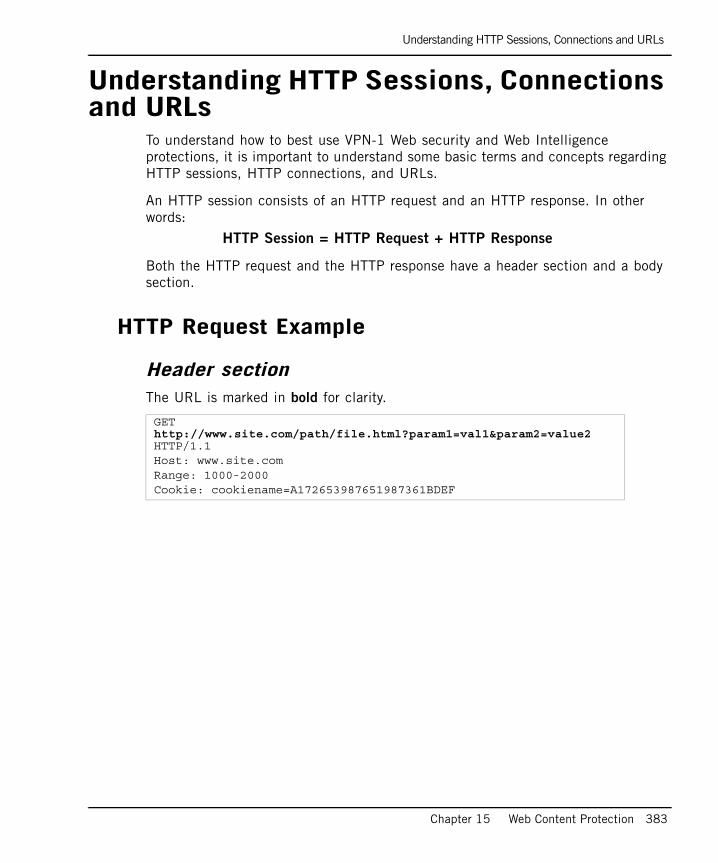
Understanding HTTP Sessions, Connections and URLs
Chapter 15 Web Content Protection 383
Understanding HTTP Sessions, Connections and URLs
To understand how to best use VPN-1 Web security and Web Intelligence protections, it is important to understand some basic terms and concepts regarding HTTP sessions, HTTP connections, and URLs.
An HTTP session consists of an HTTP request and an HTTP response. In other words:
HTTP Session = HTTP Request + HTTP Response
Both the HTTP request and the HTTP response have a header section and a body section.
HTTP Request Example
Header section The URL is marked in bold for clarity.
GET http://www.site.com/path/file.html?param1=val1¶m2=value2 HTTP/1.1Host: www.site.comRange: 1000-2000Cookie: cookiename=A172653987651987361BDEF
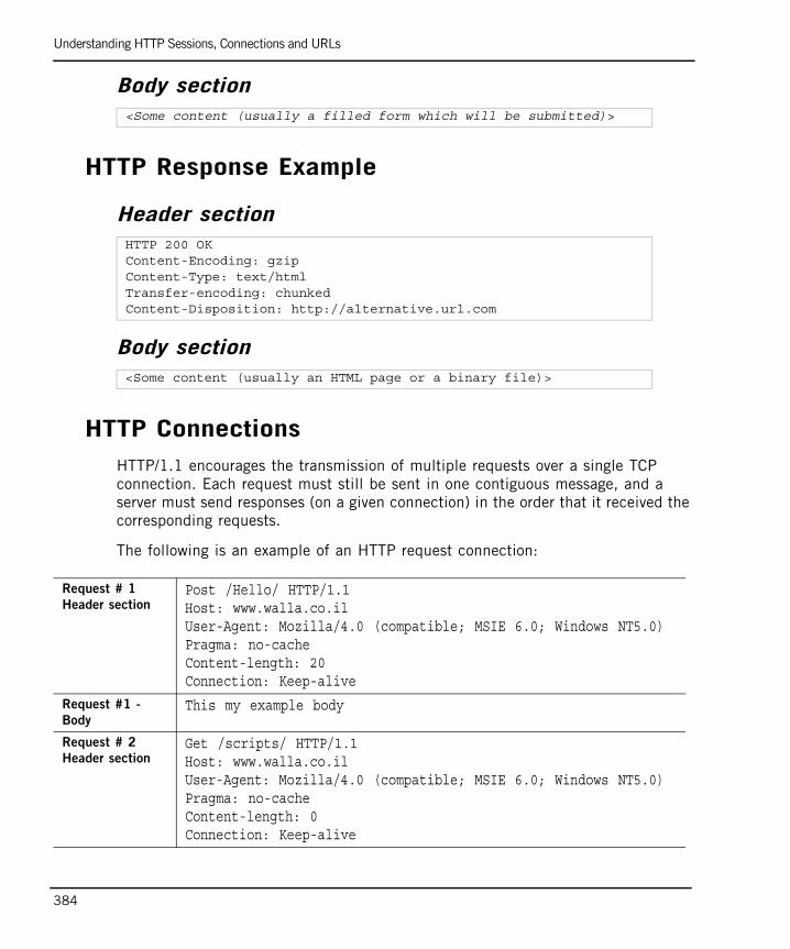
Understanding HTTP Sessions, Connections and URLs
384
Body section
HTTP Response Example
Header section
Body section
HTTP ConnectionsHTTP/1.1 encourages the transmission of multiple requests over a single TCP connection. Each request must still be sent in one contiguous message, and a server must send responses (on a given connection) in the order that it received the corresponding requests.
The following is an example of an HTTP request connection:
<Some content (usually a filled form which will be submitted)>
HTTP 200 OKContent-Encoding: gzipContent-Type: text/htmlTransfer-encoding: chunkedContent-Disposition: http://alternative.url.com
<Some content (usually an HTML page or a binary file)>
Request # 1
Header sectionPost /Hello/ HTTP/1.1Host: www.walla.co.ilUser-Agent: Mozilla/4.0 (compatible; MSIE 6.0; Windows NT5.0)Pragma: no-cacheContent-length: 20Connection: Keep-alive
Request #1 -
BodyThis my example body
Request # 2
Header sectionGet /scripts/ HTTP/1.1Host: www.walla.co.ilUser-Agent: Mozilla/4.0 (compatible; MSIE 6.0; Windows NT5.0)Pragma: no-cacheContent-length: 0Connection: Keep-alive
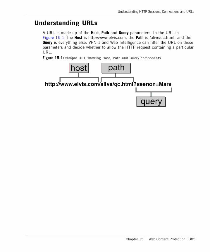
Understanding HTTP Sessions, Connections and URLs
Chapter 15 Web Content Protection 385
Understanding URLsA URL is made up of the Host, Path and Query parameters. In the URL in Figure 15-1, the Host is http://www.elvis.com, the Path is /alive/qc.html, and the Query is everything else. VPN-1 and Web Intelligence can filter the URL on these parameters and decide whether to allow the HTTP request containing a particular URL. Figure 15-1Example URL showing Host, Path and Query components
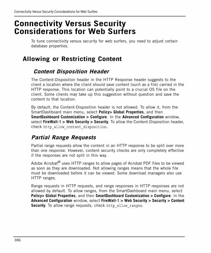
Connectivity Versus Security Considerations for Web Surfers
386
Connectivity Versus Security Considerations for Web Surfers
To tune connectivity versus security for web surfers, you need to adjust certain database properties.
Allowing or Restricting Content
Content Disposition HeaderThe Content-Disposition header in the HTTP Response header suggests to the client a location where the client should save content (such as a file) carried in the HTTP response. This location can potentially point to a crucial OS file on the client. Some clients may take up this suggestion without question and save the content to that location.
By default, the Content-Disposition header is not allowed. To allow it, from the SmartDashboard main menu, select Policy> Global Properties, and then SmartDashboard Customization > Configure. In the Advanced Configuration window, select FireWall-1 > Web Security > Security. To allow the Content-Disposition header, check http_allow_content_disposition.
Partial Range RequestsPartial range requests allow the content in an HTTP response to be split over more than one response. However, content security checks are only completely effective if the responses are not split in this way.
Adobe Acrobat® uses HTTP ranges to allow pages of Acrobat PDF files to be viewed as soon as they are downloaded. Not allowing ranges means that the whole file must be downloaded before it can be viewed. Some download managers also use HTTP ranges.
Range requests in HTTP requests, and range responses in HTTP responses are not allowed by default. To allow ranges, from the SmartDashboard main menu, select Policy> Global Properties, and then SmartDashboard Customization > Configure. In the Advanced Configuration window, select FireWall-1 > Web Security > Security > Content Security. To allow range requests, check http_allow_ranges.
Connectivity Versus Security Considerations for Web Surfers
Chapter 15 Web Content Protection 387
Content CompressionCompressing content in HTTP responses is a way of increasing the speed of the connection. However, content security checks such as HTML weeding and CVP checking cannot be performed on compressed content.
The Content-Encoding and Content-Type headers in the HTTP response indicate whether or not the content is compressed, for example: Content-Encoding: gzip, Content-Type: application/gzip.
The http_disable_content_enc and http_disable_content_type database properties control whether or not to allow data in the HTTP response to be compressed. If these properties are false (the default value), compression of content in an HTTP response is not allowed. Both these properties can be either true or false. One may be true when the other is false. Each one affects it own header.
These properties only affect content on which one or more of the following content security checks are performed: HTML weeding, blocking Java code, CVP, SOAP.
To change the value of this property, in SmartDashboard, edit the Global Properties in the SmartDashboard Customization > Advanced Configuration page, under Web Security.

Factors Affecting HTTP Security Server Performance
388
Factors Affecting HTTP Security Server Performance
On multiple CPU machines, running more than one instance of the HTTP Security server increases the performance experienced by users. This is because each Security server uses a different CPU. Run at least one Security server instance for each CPU (refer to “How To Run Multiple Instances of the HTTP Security Server” on page 389).
To allow more concurrent connections, it may well be worthwhile to run more than one Security server, even on a single CPU machine. However, this will increase the memory usage.
The Number of Simultaneous Security Server Connections
Each Security server allows up to 1024 file descriptors, which limits the number of simultaneous connections. In an ordinary connection, packets pass in both directions through the VPN-1 gateway, as follows:
1. Web client to VPN-1 to Web server (request).
2. Web server to VPN-1 to Web client (response).
512 descriptors are available for use in each direction, so that a total of 512 simultaneous connections are possible.
Where a CVP or UFP server is used, packets in each connection pass through VPN-1 three times:
1. Web client to VPN-1 to Web server (request).
2. Web server to VPN-1 to CVP/UFP server (response).
3. CVP/UFP server to VPN-1 to Web client (response).
Therefore, the available file descriptors are split three ways, so that a total of 341 simultaneous connections are possible.
Factors Affecting HTTP Security Server Performance
Chapter 15 Web Content Protection 389
How To Run Multiple Instances of the HTTP Security Server
To run multiple instances of the HTTP Security server:
1. Edit $FWDIR/conf/fwauthd.conf, and include the line
80 in.ahttpd wait -2
The last digit on the line is the number of instances of the Security server. In this example, there are two instances of the HTTP Security server.
2. Restart the VPN-1 gateway (cpstart).
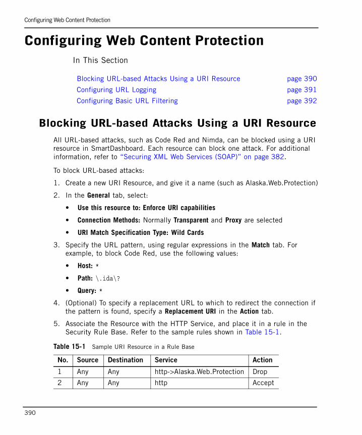
Configuring Web Content Protection
390
Configuring Web Content ProtectionIn This Section
Blocking URL-based Attacks Using a URI ResourceAll URL-based attacks, such as Code Red and Nimda, can be blocked using a URI resource in SmartDashboard. Each resource can block one attack. For additional information, refer to “Securing XML Web Services (SOAP)” on page 382.
To block URL-based attacks:
1. Create a new URI Resource, and give it a name (such as Alaska.Web.Protection)
2. In the General tab, select:
• Use this resource to: Enforce URI capabilities
• Connection Methods: Normally Transparent and Proxy are selected
• URI Match Specification Type: Wild Cards
3. Specify the URL pattern, using regular expressions in the Match tab. For example, to block Code Red, use the following values:
• Host: *
• Path: \.ida\?
• Query: *
4. (Optional) To specify a replacement URL to which to redirect the connection if the pattern is found, specify a Replacement URI in the Action tab.
5. Associate the Resource with the HTTP Service, and place it in a rule in the Security Rule Base. Refer to the sample rules shown in Table 15-1.
Blocking URL-based Attacks Using a URI Resource page 390
Configuring URL Logging page 391
Configuring Basic URL Filtering page 392
Table 15-1 Sample URI Resource in a Rule Base
No. Source Destination Service Action
1 Any Any http->Alaska.Web.Protection Drop
2 Any Any http Accept
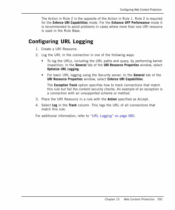
Configuring Web Content Protection
Chapter 15 Web Content Protection 391
The Action in Rule 2 is the opposite of the Action in Rule 1. Rule 2 is required for the Enforce URI Capabilities mode. For the Enhance UFP Performance mode it is recommended to avoid problems in cases where more than one URI resource is used in the Rule Base.
Configuring URL Logging1. Create a URI Resource.
2. Log the URL in the connection in one of the following ways:
• To log the URLs, including the URL paths and query, by performing kernel inspection: In the General tab of the URI Resource Properties window, select Optimize URL Logging.
• For basic URL logging using the Security server: In the General tab of the URI Resource Properties window, select Enforce URI Capabilities.
The Exception Track option specifies how to track connections that match this rule but fail the content security checks. An example of an exception is a connection with an unsupported scheme or method.
3. Place the URI Resource in a rule with the Action specified as Accept.
4. Select Log in the Track column. This logs the URL of all connections that match this rule.
For additional information, refer to “URL Logging” on page 380.
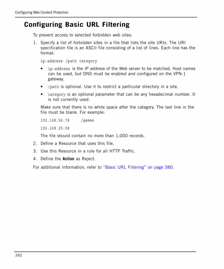
Configuring Web Content Protection
392
Configuring Basic URL FilteringTo prevent access to selected forbidden web sites:
1. Specify a list of forbidden sites in a file that lists the site URIs. The URI specification file is an ASCII file consisting of a list of lines. Each line has the format:
ip-address /path category
• ip-address is the IP address of the Web server to be matched. Host names can be used, but DNS must be enabled and configured on the VPN-1 gateway.
• /path is optional. Use it to restrict a particular directory in a site.
• category is an optional parameter that can be any hexadecimal number. It is not currently used.
Make sure that there is no white space after the category. The last line in the file must be blank. For example:
192.168.56.78 /games
192.168.25.58
The file should contain no more than 1,000 records.
2. Define a Resource that uses this file.
3. Use this Resource in a rule for all HTTP Traffic.
4. Define the Action as Reject.
For additional information, refer to “Basic URL Filtering” on page 380.
AppendicesThis section describes how the VPN-1 machine protects itself and the networks behind it upon activation, and the command line interface.

395
Appendix ASecurity BeforeVPN-1 Activation
In This Appendix
Achieving Security Before VPN-1 Activation page 396
Boot Security page 396
The Initial Policy page 399
Default Filter and Initial Policy Configuration page 402
Achieving Security Before VPN-1 Activation
396
Achieving Security Before VPN-1 ActivationThere are several scenarios in which a computer does not yet have a VPN-1 security policy installed and is vulnerable. Two features provide security during these situations: Boot Security, which secures communication during the boot period, and Initial Policy, which provides security before a security policy is installed for the first time. As a result, there is no point in time when the computer is left unprotected.
Boot SecurityDuring the boot process, there is a short period of time (measured in seconds) between the point when the computer is capable of receiving communication (and can be attacked) and the point when the security policy is loaded and is enforced. During this time, VPN-1 Boot Security feature protects both the internal networks behind the VPN-1 gateway, and the computer itself. Boot Security is provided by two elements working together:
• Control of IP Forwarding on boot
• Default Filter
The Default Filter also provides protection in a scenario where VPN-1 processes are stopped for maintenance.
Control of IP Forwarding on BootFor networks protected by a VPN-1 gateway, protection is available at boot by disabling IP forwarding in the OS kernel. This ensures that there will never be a time when IP Forwarding is active and no security policy is enforced. This ensures that networks behind the gateway are safe.
Disabling IP Forwarding protects networks behind the VPN-1 computer, but it does not protect the VPN-1 computer itself. For this purpose, VPN-1 implements a Default Filter during the period of vulnerability.
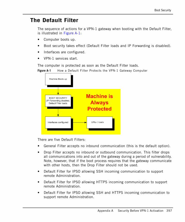
Boot Security
Appendix A Security Before VPN-1 Activation 397
The Default Filter The sequence of actions for a VPN-1 gateway when booting with the Default Filter, is illustrated in Figure A-1:
• Computer boots up.
• Boot security takes effect (Default Filter loads and IP Forwarding is disabled).
• Interfaces are configured.
• VPN-1 services start.
The computer is protected as soon as the Default Filter loads.Figure A-1 How a Default Filter Protects the VPN-1 Gateway Computer
There are five Default Filters:
• General Filter accepts no inbound communication (this is the default option).
• Drop Filter accepts no inbound or outbound communication. This filter drops all communications into and out of the gateway during a period of vulnerability. Note, however, that if the boot process requires that the gateway communicate with other hosts, then the Drop Filter should not be used.
• Default Filter for IPSO allowing SSH incoming communication to support remote Administration.
• Default Filter for IPSO allowing HTTPS incoming communication to support remote Administration.
• Default Filter for IPSO allowing SSH and HTTPS incoming communication to support remote Administration.
Boot Security
398
The appropriate Default Filter should be selected based on platform and communication needs. The General Filter is selected by default.
The Default Filter also provides anti-spoofing protection for the VPN-1 gateway. It ensures that packets whose source are the VPN-1 gateway computer itself have not come from one of its interfaces.
Using the Default Filter for MaintenanceIt is possible to stop VPN-1 processes for maintenance while at the same time protecting the VPN-1 gateway and the internal network.
During maintenance, the Default Filter allows open connections to the gateway to remain open, without dropping them.
The Initial Policy
Appendix A Security Before VPN-1 Activation 399
The Initial PolicyUntil the VPN-1 administrator installs the security policy on the gateway for the first time, security is enforced by an Initial Policy. The Initial Policy operates by adding “implied rules” to the Default Filter. These rules forbid most communication yet allows the communication needed for the installation of the security policy. The Initial Policy also protects a gateway during Check Point product upgrades, when a SIC certificate is reset on the gateway, or in the case of a Check Point product license expiration.
The sequence of actions during boot of the VPN-1 gateway computer until a security policy is loaded for the first time, is illustrated in Figure A-2.
• The computer boots up.
• The Default Filter loads and IP Forwarding is disabled.
• The Interfaces are configured.
• VPN-1 services start.
• The Initial policy is fetched from the local gateway.
• SmartConsole clients connect or Trust is established, and the security policy is installed.
Note - During a Check Point upgrade, a SIC certificate reset, or license expiration, the Initial Policy overwrites the user-defined policy.

The Initial Policy
400
Figure A-2 Initial Policy- Until the First Policy Installation
The Initial Policy is enforced until a policy is installed, and is never loaded again. In subsequent boots, the regular policy is loaded immediately after the Default Filter.
There are different Initial Policies for standalone and distributed setups. In a standalone configuration, where the SmartCenter server and VPN-1 gateway are on the same computer, the Initial Policy allows CPMI communication only. This permits SmartConsole clients to connect to the SmartCenter server.
The Initial Policy
Appendix A Security Before VPN-1 Activation 401
In a distributed configuration, where the Primary SmartCenter server is on one computer and the VPN-1 gateway is on a different computer, the Initial Policy allows the following:
• Primary SmartCenter server computer — allows CPMI communication for SmartConsole clients.
• VPN-1 Gateway — allows cpd and fwd communication for SIC communication (to establish trust) and for Policy installation.
In a distributed configuration, the Initial Policy on the VPN-1 gateway does not allow CPMI connections. The SmartConsole will not be able to connect to the SmartCenter server if the SmartConsole must access the SmartCenter server through a gateway running the Initial Policy.
There is also an Initial Policy for a Secondary SmartCenter server (Management High Availability). This Initial Policy allows CPMI communication for SmartConsole clients and allows cpd and fwd communication for SIC communication (to establish trust) and for Policy installation.

Default Filter and Initial Policy Configuration
402
Default Filter and Initial Policy Configuration
In This Section
Verifying Default Filter or Initial Policy LoadingYou can verify that the Default Filter and/or Initial Policy are loaded.
To verify loading of the Default Filter or Initial Policy:
1. Boot the system.
2. Before installing another security policy, type the following command:
The command’s output should show that defaultfilter is installed for the Default Filter status. It should show that InitialPolicy is installed for the Initial Policy.
Verifying Default Filter or Initial Policy Loading page 402
Change the Default Filter to a Drop Filter page 403
User-Defined Default Filter page 403
Using the Default Filter for Maintenance page 404
To Unload a Default Filter or an Initial Policy page 404
If You Cannot Complete Reboot After Installation page 404
Command Line Reference for Default Filter and Initial Policy page 405
$FWDIR/bin/fw stat

Default Filter and Initial Policy Configuration
Appendix A Security Before VPN-1 Activation 403
Change the Default Filter to a Drop FilterFor a typical setup there are two Default Filters: defaultfilter.boot and defaultfilter.drop. They are located in $FWDIR/lib.
To change the Default Filter:
1. Copy over and rename the relevant desired Default Filter Inspect file (defaultfilter.boot or defaultfilter.drop) to $FWDIR/conf/defaultfilter.pf
2. Compile the Default Filter by running the command:
fw defaultgen
The output will be in $FWDIR/state/default.bin
3. Run fwboot bootconf get_def to print the Default Filter file path.
4. Copy default.bin to the Default Filter file path.
5. If the security policy has not yet been installed, run cpconfig to regenerate the Initial Policy.
User-Defined Default FilterFor administrators with Inspect knowledge, it is possible to define your own Default Filter.
To define a Default Filter:
1. Create an Inspect script named defaultfilter.pf in $FWDIR/conf:
2. Continue from step 2 of “Change the Default Filter to a Drop Filter” on page 403.”
You must ensure that your security policy does not interfere with the boot process.
Warning - Ensure that the script does not perform any of the following functions:
• Logging
• Authentication
• Encryption
• Content security

Default Filter and Initial Policy Configuration
404
Using the Default Filter for MaintenanceIt is sometimes necessary to stop VPN-1 processes for maintenance, and it is impractical to disconnect the VPN-1 gateway computer from the network (for example, the computer may be at a remote location). The cpstop -fwflag -default and cpstop -fwflag -proc commands allow VPN-1 processes to be temporarily stopped for remote maintenance without exposing the computer to attack.
To Unload a Default Filter or an Initial PolicyTo unload a Default Filter or an Initial Policy from the kernel, use the same command that is used for unloading a regular policy. Do this only if you are certain that you do not need the security provided by the Default Filter or an Initial Policy.
• To unload the Default Filter locally, run the fw unloadlocal command.
• To unload an Initial Policy from a remote SmartCenter machine, run the following command on the SmartCenter server:
fwm unload <hostname>
where hostname is the SIC_name of the gateway.
If You Cannot Complete Reboot After InstallationIn certain configurations the Default Filter may prevent the VPN-1 gateway computer from completing the reboot following installation.
First, examine the Default Filter and verify that the Default Filter allows traffic that the computer needs in order to boot.
If the boot process cannot complete successfully, remove the Default Filter as follows:
1. Reboot in single user mode (for UNIX) or Safe Mode With No Networking (for Windows 2000).
2. Ensure that the Default Filter does not load in future boots. Use the commandfwbootconf bootconf Set_def
3. Reboot.
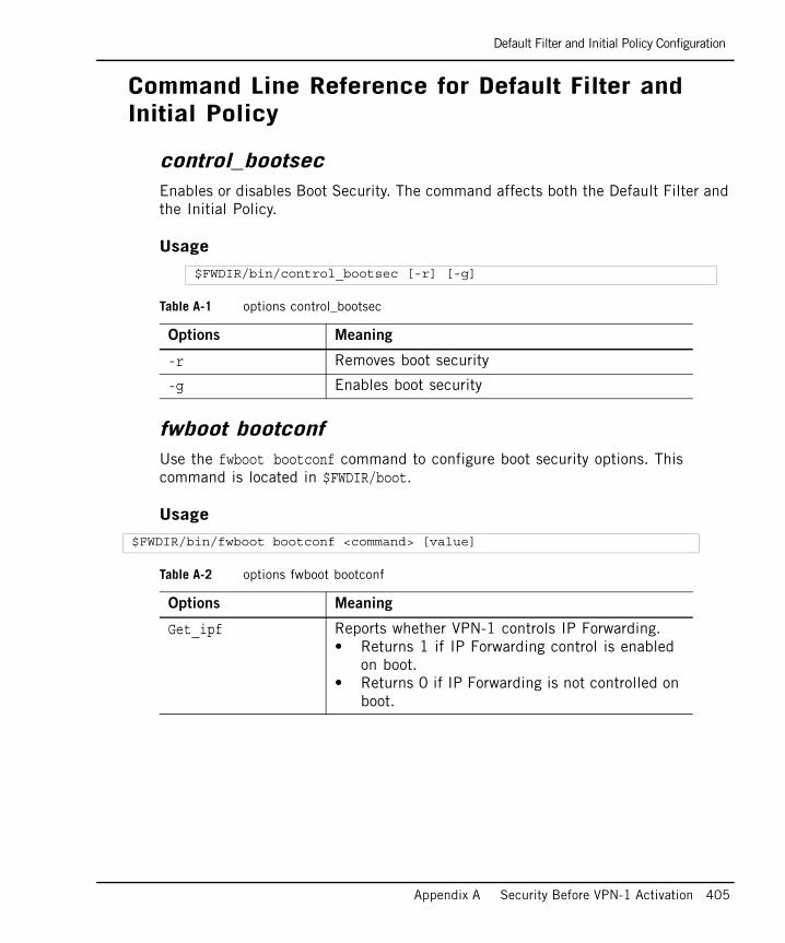
Default Filter and Initial Policy Configuration
Appendix A Security Before VPN-1 Activation 405
Command Line Reference for Default Filter and Initial Policy
control_bootsecEnables or disables Boot Security. The command affects both the Default Filter and the Initial Policy.
Usage
fwboot bootconf Use the fwboot bootconf command to configure boot security options. This command is located in $FWDIR/boot.
Usage
$FWDIR/bin/control_bootsec [-r] [-g]
Table A-1 options control_bootsec
Options Meaning
-r Removes boot security
-g Enables boot security
$FWDIR/bin/fwboot bootconf <command> [value]
Table A-2 options fwboot bootconf
Options Meaning
Get_ipf Reports whether VPN-1 controls IP Forwarding. • Returns 1 if IP Forwarding control is enabled
on boot. • Returns 0 if IP Forwarding is not controlled on
boot.
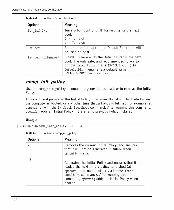
Default Filter and Initial Policy Configuration
406
comp_init_policyUse the comp_init_policy command to generate and load, or to remove, the Initial Policy.
This command generates the Initial Policy. It ensures that it will be loaded when the computer is booted, or any other time that a Policy is fetched, for example, at cpstart, or with the fw fetch localhost command. After running this command, cpconfig adds an Initial Policy if there is no previous Policy installed.
Usage
Set_ipf 0/1 Turns off/on control of IP forwarding for the next boot. 0 - Turns off1 - Turns on
Get_def Returns the full path to the Default Filter that will be used on boot.
Set_def <filename> Loads <filename> as the Default Filter in the next boot. The only safe, and recommended, place to put the default.bin file is $FWDIR\boot. (The default.bin filename is a default name.)
Note - Do NOT move these files.
Table A-2 options fwboot bootconf
Options Meaning
$FWDIR/bin/comp_init_policy [-u | -g]
Table A-3 options comp_init_policy
Options Meaning
-u Removes the current Initial Policy, and ensures that it will not be generated in future when cpconfig is run.
-gGenerates the Initial Policy and ensures that it is loaded the next time a policy is fetched (at cpstart, or at next boot, or via the fw fetch localhost command). After running this command, cpconfig adds an Initial Policy when needed.
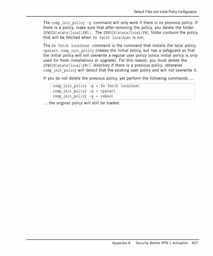
Default Filter and Initial Policy Configuration
Appendix A Security Before VPN-1 Activation 407
The comp_init_policy -g command will only work if there is no previous policy. If there is a policy, make sure that after removing the policy, you delete the folder $FWDIR\state\local\FW1\. The $FWDIR/state/local/FW1 folder contains the policy that will be fetched when fw fetch localhost is run.
The fw fetch localhost command is the command that installs the local policy. cpstart. comp_init_policy creates the initial policy, but has a safeguard so that the initial policy will not overwrite a regular user policy (since initial policy is only used for fresh installations or upgrade). For this reason, you must delete the $FWDIR\state\local\FW1\ directory if there is a previous policy, otherwise comp_init_policy will detect that the existing user policy and will not overwrite it.
If you do not delete the previous policy, yet perform the following commands …
… the original policy will still be loaded.
comp_init_policy -g + fw fetch localhostcomp_init_policy -g + cpstartcomp_init_policy -g + reboot
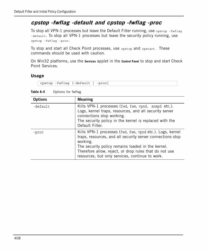
Default Filter and Initial Policy Configuration
408
cpstop -fwflag -default and cpstop -fwflag -procTo stop all VPN-1 processes but leave the Default Filter running, use cpstop -fwflag
-default. To stop all VPN-1 processes but leave the security policy running, use cpstop -fwflag -proc.
To stop and start all Check Point processes, use cpstop and cpstart. These commands should be used with caution.
On Win32 platforms, use the Services applet in the Control Panel to stop and start Check Point Services.
Usage
cpstop -fwflag [-default | -proc]
Table A-4 Options for fwflag
Options Meaning
-default Kills VPN-1 processes (fwd, fwm, vpnd, snmpd etc.). Logs, kernel traps, resources, and all security server connections stop working.The security policy in the kernel is replaced with the Default Filter.
-proc Kills VPN-1 processes (fwd, fwm, vpnd etc.). Logs, kernel traps, resources, and all security server connections stop working.The security policy remains loaded in the kernel. Therefore allow, reject, or drop rules that do not use resources, but only services, continue to work.
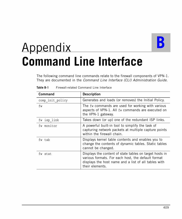
409
Appendix BCommand Line Interface
The following command line commands relate to the firewall components of VPN-1. They are documented in the Command Line Interface (CLI) Administration Guide.
Table B-1 Firewall-related Command Line Interface
Command Description
comp_init_policy Generates and loads (or removes) the Initial Policy.
fw The fw commands are used for working with various aspects of VPN-1. All fw commands are executed on the VPN-1 gateway.
fw isp_link Takes down (or up) one of the redundant ISP links.
fw monitor A powerful built-in tool to simplify the task of capturing network packets at multiple capture points within the firewall chain.
fw tab Displays kernel table contents and enables you to change the contents of dynamic tables. Static tables cannot be changed.
fw stat Displays the content of state tables on target hosts in various formats. For each host, the default format displays the host name and a list of all tables with their elements.

410
fw ver Displays the VPN-1 major and minor version number and build number.
sam_alert Executes VPN-1 SAM (Suspicious Activity Monitoring) actions according to information received through standard input. This tool is for executing SAM actions with the User Defined alerts mechanism. It is normally run on on the SmartCenter server.
svr_webupload_config This utility is used to configure the Eventia Reporter web upload script.
Table B-1 Firewall-related Command Line Interface (continued)
Command Description
411
THIRD PARTY TRADEMARKS AND COPYRIGHTS
Entrust is a registered trademark of Entrust Technologies, Inc. in the United States and other countries. Entrust’s logos and Entrust product and service names are also trademarks of Entrust Technologies, Inc. Entrust Technologies Limited is a wholly owned subsidiary of Entrust Technologies, Inc. FireWall-1 and SecuRemote incorporate certificate management technology from Entrust.
Verisign is a trademark of Verisign Inc.
The following statements refer to those portions of the software copyrighted by University of Michigan. Portions of the software copyright © 1992-1996 Regents of the University of Michigan. All rights reserved. Redistribution and use in source and binary forms are permitted provided that this notice is preserved and that due credit is given to the University of Michigan at Ann Arbor. The name of the University may not be used to endorse or promote products derived from this software without specific prior written permission. This software is provided “as is” without express or implied warranty. Copyright © Sax Software (terminal emulation only).
The following statements refer to those portions of the software copyrighted by Carnegie Mellon University.
Copyright 1997 by Carnegie Mellon University. All Rights Reserved.
Permission to use, copy, modify, and distribute this software and its documentation for any purpose and without fee is hereby granted, provided that the above copyright notice appear in all copies and that both that copyright notice and this permission notice appear in supporting documentation, and that the name of CMU not be used in advertising or publicity pertaining to distribution of the software without specific, written prior permission.CMU DISCLAIMS ALL WARRANTIES WITH REGARD TO THIS SOFTWARE, INCLUDING ALL IMPLIED WARRANTIES OF MERCHANTABILITY AND FITNESS, IN NO EVENT SHALL CMU BE LIABLE FOR ANY SPECIAL, INDIRECT OR CONSEQUENTIAL DAMAGES OR ANY DAMAGES WHATSOEVER RESULTING FROM LOSS OF USE, DATA OR PROFITS, WHETHER IN AN ACTION OF CONTRACT, NEGLIGENCE OR OTHER TORTIOUS ACTION, ARISING OUT OF OR IN CONNECTION WITH THE USE OR PERFORMANCE OF THIS SOFTWARE.
The following statements refer to those portions of the software copyrighted by The Open Group.
THE SOFTWARE IS PROVIDED "AS IS", WITHOUT WARRANTY OF ANY KIND, EXPRESS OR IMPLIED, INCLUDING BUT NOT LIMITED TO THE WARRANTIES OF MERCHANTABILITY, FITNESS FOR A PARTICULAR PURPOSE AND NONINFRINGEMENT. IN NO EVENT SHALL THE OPEN GROUP BE LIABLE FOR ANY CLAIM, DAMAGES OR OTHER LIABILITY, WHETHER IN AN ACTION OF CONTRACT, TORT OR OTHERWISE, ARISING FROM, OUT OF OR IN CONNECTION WITH THE SOFTWARE OR THE USE OR OTHER DEALINGS IN THE SOFTWARE.
The following statements refer to those portions of the software copyrighted by The OpenSSL Project. This product includes software developed by the OpenSSL Project for use in the OpenSSL Toolkit (http://www.openssl.org/).
THIS SOFTWARE IS PROVIDED BY THE OpenSSL PROJECT ``AS IS'' AND ANY * EXPRESSED OR IMPLIED WARRANTIES, INCLUDING, BUT NOT LIMITED TO, THE IMPLIED WARRANTIES OF MERCHANTABILITY AND FITNESS FOR A PARTICULAR PURPOSE ARE DISCLAIMED. IN NO EVENT SHALL THE OpenSSL PROJECT OR ITS CONTRIBUTORS BE LIABLE FOR ANY DIRECT, INDIRECT, INCIDENTAL, SPECIAL, EXEMPLARY, OR CONSEQUENTIAL DAMAGES (INCLUDING, BUT NOT LIMITED TO, PROCUREMENT OF SUBSTITUTE GOODS OR SERVICES; LOSS OF USE, DATA, OR PROFITS; OR BUSINESS INTERRUPTION) HOWEVER CAUSED AND ON ANY THEORY OF LIABILITY, WHETHER IN CONTRACT, STRICT LIABILITY, OR TORT (INCLUDING NEGLIGENCE OR OTHERWISE) ARISING IN ANY WAY OUT OF THE USE OF THIS SOFTWARE, EVEN IF ADVISED OF THE POSSIBILITY OF SUCH DAMAGE.
The following statements refer to those portions of the software copyrighted by Eric Young. THIS SOFTWARE IS PROVIDED BY ERIC YOUNG ``AS IS'' AND ANY EXPRESS OR IMPLIED WARRANTIES, INCLUDING, BUT NOT LIMITED TO, THE IMPLIED WARRANTIES OF MERCHANTABILITY AND FITNESS FOR A PARTICULAR PURPOSE ARE DISCLAIMED. IN NO EVENT SHALL THE AUTHOR OR CONTRIBUTORS BE LIABLE FOR ANY DIRECT, INDIRECT, INCIDENTAL, SPECIAL, EXEMPLARY, OR CONSEQUENTIAL DAMAGES (INCLUDING, BUT NOT LIMITED TO, PROCUREMENT OF SUBSTITUTE GOODS OR SERVICES; LOSS OF USE, DATA, OR PROFITS; OR BUSINESS INTERRUPTION) HOWEVER CAUSED AND ON ANY THEORY OF LIABILITY, WHETHER IN CONTRACT, STRICT LIABILITY, OR TORT (INCLUDING NEGLIGENCE OR OTHERWISE) ARISING IN ANY WAY OUT OF THE USE OF THIS SOFTWARE, EVEN IF ADVISED OF THE POSSIBILITY OF SUCH DAMAGE. Copyright © 1998 The Open Group.
412
The following statements refer to those portions of the software copyrighted by Jean-loup Gailly and Mark Adler Copyright (C) 1995-2002 Jean-loup Gailly and Mark Adler. This software is provided 'as-is', without any express or implied warranty. In no event will the authors be held liable for any damages arising from the use of this software. Permission is granted to anyone to use this software for any purpose, including commercial applications, and to alter it and redistribute it freely, subject to the following restrictions:
1. The origin of this software must not be misrepresented; you must not claim that you wrote the original software. If you use this software in a product, an acknowledgment in the product documentation would be appreciated but is not required.
2. Altered source versions must be plainly marked as such, and must not be misrepresented as being the original software.
3. This notice may not be removed or altered from any source distribution.
The following statements refer to those portions of the software copyrighted by the Gnu Public License. This program is free software; you can redistribute it and/or modify it under the terms of the GNU General Public License as published by the Free Software Foundation; either version 2 of the License, or (at your option) any later version. This program is distributed in the hope that it will be useful, but WITHOUT ANY WARRANTY; without even the implied warranty of MERCHANTABILITY or FITNESS FOR A PARTICULAR PURPOSE. See the GNU General Public License for more details.You should have received a copy of the GNU General Public License along with this program; if not, write to the Free Software Foundation, Inc., 675 Mass Ave, Cambridge, MA 02139, USA.
The following statements refer to those portions of the software copyrighted by Thai Open Source Software Center Ltd and Clark Cooper Copyright (c) 2001, 2002 Expat maintainers. Permission is hereby granted, free of charge, to any person obtaining a copy of this software and associated documentation files (the "Software"), to deal in the Software without restriction, including without limitation the rights to use, copy, modify, merge, publish, distribute, sublicense, and/or sell copies of the Software, and to permit persons to whom the Software is furnished to do so, subject to the following conditions: The above copyright notice and this permission notice shall be included in all copies or substantial portions of the Software. THE SOFTWARE IS PROVIDED "AS IS", WITHOUT WARRANTY OF ANY KIND, EXPRESS OR IMPLIED, INCLUDING BUT NOT LIMITED TO THE WARRANTIES OF MERCHANTABILITY, FITNESS FOR A PARTICULAR PURPOSE AND NONINFRINGEMENT. IN NO EVENT SHALL THE AUTHORS OR COPYRIGHT HOLDERS BE LIABLE FOR ANY CLAIM, DAMAGES OR OTHER LIABILITY, WHETHER IN AN ACTION OF CONTRACT, TORT OR OTHERWISE, ARISING FROM, OUT OF OR IN CONNECTION WITH THE SOFTWARE OR THE USE OR OTHER DEALINGS IN THE SOFTWARE.GDChart is free for use in your applications and for chart generation. YOU MAY NOT re-distribute or represent the code as your own. Any re-distributions of the code MUST reference the author, and include any and all original documentation. Copyright. Bruce Verderaime. 1998, 1999, 2000, 2001. Portions copyright 1994, 1995, 1996, 1997, 1998, 1999, 2000, 2001, 2002 by Cold Spring Harbor Laboratory. Funded under Grant P41-RR02188 by the National Institutes of Health. Portions copyright 1996, 1997, 1998, 1999, 2000, 2001, 2002 by Boutell.Com, Inc. Portions relating to GD2 format copyright 1999, 2000, 2001, 2002 Philip Warner. Portions relating to PNG copyright 1999, 2000, 2001, 2002 Greg Roelofs. Portions relating to gdttf.c copyright 1999, 2000, 2001, 2002 John Ellson ([email protected]). Portions relating to gdft.c copyright 2001, 2002 John Ellson ([email protected]). Portions relating to JPEG and to color quantization copyright 2000, 2001, 2002, Doug Becker and copyright (C) 1994, 1995, 1996, 1997, 1998, 1999, 2000, 2001, 2002, Thomas G. Lane. This software is based in part on the work of the Independent JPEG Group. See the file README-JPEG.TXT for more information. Portions relating to WBMP copyright 2000, 2001, 2002 Maurice Szmurlo and Johan Van den Brande. Permission has been granted to copy, distribute and modify gd in any context without fee, including a commercial application, provided that this notice is present in user-accessible supporting documentation. This does not affect your ownership of the derived work itself, and the intent is to assure proper credit for the authors of gd, not to interfere with your productive use of gd. If you have questions, ask. "Derived works" includes all programs that utilize the library. Credit must be given in user-accessible documentation. This software is provided "AS IS." The copyright holders disclaim all warranties, either express or implied, including but not limited to implied warranties of merchantability and fitness for a particular purpose, with respect to this code and accompanying documentation. Although their code does not appear in gd 2.0.4, the authors wish to thank David Koblas, David Rowley, and Hutchison Avenue Software Corporation for their prior contributions.
Licensed under the Apache License, Version 2.0 (the "License"); you may not use this file except in compliance with the License. You may obtain a copy of the License at http://www.apache.org/licenses/LICENSE-2.0
The curl license
COPYRIGHT AND PERMISSION NOTICE
Copyright (c) 1996 - 2004, Daniel Stenberg, <[email protected]>.All rights reserved.
Permission to use, copy, modify, and distribute this software for any purpose
with or without fee is hereby granted, provided that the above copyright
notice and this permission notice appear in all copies.
413
THE SOFTWARE IS PROVIDED "AS IS", WITHOUT WARRANTY OF ANY KIND, EXPRESS OR IMPLIED, INCLUDING BUT NOT LIMITED TO THE WARRANTIES OF MERCHANTABILITY, FITNESS FOR A PARTICULAR PURPOSE AND NONINFRINGEMENT OF THIRD PARTY RIGHTS. IN NO EVENT SHALL THE AUTHORS OR COPYRIGHT HOLDERS BE LIABLE FOR ANY CLAIM, DAMAGES OR OTHER LIABILITY, WHETHER IN AN ACTION OF CONTRACT, TORT OR OTHERWISE, ARISING FROM, OUT OF OR IN CONNECTION WITH THE SOFTWARE OR THE USE OR OTHER DEALINGS IN THE SOFTWARE.
Except as contained in this notice, the name of a copyright holder shall not be used in advertising or otherwise to promote the sale, use or other dealings in this Software without prior written authorization of the copyright holder.
The PHP License, version 3.0
Copyright (c) 1999 - 2004 The PHP Group. All rights reserved.
Redistribution and use in source and binary forms, with or without modification, is permitted provided that the following conditions are met:
1. Redistributions of source code must retain the above copyright notice, this list of conditions and the following disclaimer.
2. Redistributions in binary form must reproduce the above copyright notice, this list of conditions and the following disclaimer in the documentation and/or other materials provided with the distribution.
3. The name "PHP" must not be used to endorse or promote products derived from this software without prior written permission. For written permission, please contact [email protected].
4. Products derived from this software may not be called "PHP", nor may "PHP" appear in their name, without prior written permission from [email protected]. You may indicate that your software works in conjunction with PHP by saying "Foo for PHP" instead of calling it "PHP Foo" or "phpfoo"
5. The PHP Group may publish revised and/or new versions of the license from time to time. Each version will be given a distinguishing version number. Once covered code has been published under a particular version of the license, you may always continue to use it under the terms of that version. You may also choose to use such covered code under the terms of any subsequent version of the license published by the PHP Group. No one other than the PHP Group has the right to modify the terms applicable to covered code created under this License.
6. Redistributions of any form whatsoever must retain the following acknowledgment:
"This product includes PHP, freely available from <http://www.php.net/>".
THIS SOFTWARE IS PROVIDED BY THE PHP DEVELOPMENT TEAM ``AS IS'' AND ANY EXPRESSED OR IMPLIED WARRANTIES, INCLUDING, BUT NOT LIMITED TO, THE IMPLIED WARRANTIES OF MERCHANTABILITY AND FITNESS FOR A PARTICULAR PURPOSE ARE DISCLAIMED. IN NO EVENT SHALL THE PHP DEVELOPMENT TEAM OR ITS CONTRIBUTORS BE LIABLE FOR ANY DIRECT, INDIRECT, INCIDENTAL, SPECIAL, EXEMPLARY, OR CONSEQUENTIAL DAMAGES (INCLUDING, BUT NOT LIMITED TO, PROCUREMENT OF SUBSTITUTE GOODS OR SERVICES; LOSS OF USE, DATA, OR PROFITS; OR BUSINESS INTERRUPTION) HOWEVER CAUSED AND ON ANY THEORY OF LIABILITY, WHETHER IN CONTRACT, STRICT LIABILITY, OR TORT (INCLUDING NEGLIGENCE OR OTHERWISE) ARISING IN ANY WAY OUT OF THE USE OF THIS SOFTWARE, EVEN IF ADVISED OF THE POSSIBILITY OF SUCH DAMAGE.
This software consists of voluntary contributions made by many individuals on behalf of the PHP Group. The PHP Group can be contacted via Email at [email protected].
For more information on the PHP Group and the PHP project, please see <http://www.php.net>. This product includes the Zend Engine, freely available at <http://www.zend.com>.
This product includes software written by Tim Hudson ([email protected]).
THIS SOFTWARE IS PROVIDED BY THE COPYRIGHT HOLDERS AND CONTRIBUTORS "AS IS" AND ANY EXPRESS OR IMPLIED WARRANTIES, INCLUDING, BUT NOT LIMITED TO, THE IMPLIED WARRANTIES OF MERCHANTABILITY AND FITNESS FOR A PARTICULAR PURPOSE ARE DISCLAIMED. IN NO EVENT SHALL THE COPYRIGHT OWNER OR CONTRIBUTORS BE LIABLE FOR ANY DIRECT, INDIRECT, INCIDENTAL, SPECIAL, EXEMPLARY, OR CONSEQUENTIAL DAMAGES (INCLUDING, BUT NOT LIMITED TO, PROCUREMENT OF SUBSTITUTE GOODS OR SERVICES; LOSS OF USE, DATA, OR PROFITS; OR BUSINESS
INTERRUPTION) HOWEVER CAUSED AND ON ANY THEORY OF LIABILITY, WHETHER IN CONTRACT, STRICT LIABILITY, OR TORT (INCLUDING NEGLIGENCE OR OTHERWISE) ARISING IN ANY WAY OUT OF THE USE OF THIS SOFTWARE, EVEN IF ADVISED OF THE POSSIBILITY OF SUCH DAMAGE.
Copyright (c) 1998, 1999, 2000 Thai Open Source Software Center Ltd
414
Permission is hereby granted, free of charge, to any person obtaining a copy of this software and associated documentation files (the "Software"), to deal in the Software without restriction, including without limitation the rights to use, copy, modify, merge, publish, distribute, sublicense, and/or sell copies of the Software, and to permit persons to whom the Software is furnished to do so, subject to the following conditions: The above copyright notice and this permission notice shall be included in all copies or substantial portions of the Software.
THE SOFTWARE IS PROVIDED "AS IS", WITHOUT WARRANTY OF ANY KIND, EXPRESS OR IMPLIED, INCLUDING BUT NOT LIMITED TO THE WARRANTIES OF MERCHANTABILITY, FITNESS FOR A PARTICULAR PURPOSE AND NONINFRINGEMENT. IN NO EVENT SHALL THE AUTHORS OR COPYRIGHT HOLDERS BE LIABLE FOR ANY CLAIM, DAMAGES OR OTHER LIABILITY, WHETHER IN AN ACTION OF CONTRACT, TORT OR OTHERWISE, ARISING FROM, OUT OF OR IN CONNECTION WITH THE SOFTWARE OR THE USE OR OTHER DEALINGS IN THE SOFTWARE.
Copyright © 2003, 2004 NextHop Technologies, Inc. All rights reserved.
Confidential Copyright Notice
Except as stated herein, none of the material provided as a part of this document may be copied, reproduced, distrib-uted, republished, downloaded, displayed, posted or transmitted in any form or by any means, including, but not lim-ited to, electronic, mechanical, photocopying, recording, or otherwise, without the prior written permission of NextHop Technologies, Inc. Permission is granted to display, copy, distribute and download the materials in this doc-ument for personal, non-commercial use only, provided you do not modify the materials and that you retain all copy-right and other proprietary notices contained in the materials unless otherwise stated. No material contained in this document may be "mirrored" on any server without written permission of NextHop. Any unauthorized use of any material contained in this document may violate copyright laws, trademark laws, the laws of privacy and publicity, and communications regulations and statutes. Permission terminates automatically if any of these terms or condi-tions are breached. Upon termination, any downloaded and printed materials must be immediately destroyed.
Trademark Notice
The trademarks, service marks, and logos (the "Trademarks") used and displayed in this document are registered and unregistered Trademarks of NextHop in the US and/or other countries. The names of actual companies and products mentioned herein may be Trademarks of their respective owners. Nothing in this document should be construed as granting, by implication, estoppel, or otherwise, any license or right to use any Trademark displayed in the document. The owners aggressively enforce their intellectual property rights to the fullest extent of the law. The Trademarks may not be used in any way, including in advertising or publicity pertaining to distribution of, or access to, materials in
this document, including use, without prior, written permission. Use of Trademarks as a "hot" link to any website is prohibited unless establishment of such a link is approved in advance in writing. Any questions concerning the use of these Trademarks should be referred to NextHop at U.S. +1 734 222 1600.
U.S. Government Restricted Rights
The material in document is provided with "RESTRICTED RIGHTS." Software and accompanying documentation are provided to the U.S. government ("Government") in a transaction subject to the Federal Acquisition Regulations with Restricted Rights. The Government's rights to use, modify, reproduce, release, perform, display or disclose are
restricted by paragraph (b)(3) of the Rights in Noncommercial Computer Software and Noncommercial Computer Soft-ware Documentation clause at DFAR 252.227-7014 (Jun 1995), and the other restrictions and terms in paragraph (g)(3)(i) of Rights in Data-General clause at FAR 52.227-14, Alternative III (Jun 87) and paragraph (c)(2) of the Commer-cial
Computer Software-Restricted Rights clause at FAR 52.227-19 (Jun 1987).
Use of the material in this document by the Government constitutes acknowledgment of NextHop's proprietary rights in them, or that of the original creator. The Contractor/Licensor is NextHop located at 1911 Landings Drive, Mountain View, California 94043. Use, duplication, or disclosure by the Government is subject to restrictions as set forth in applicable laws and regulations.
Disclaimer Warranty Disclaimer Warranty Disclaimer Warranty Disclaimer Warranty
THE MATERIAL IN THIS DOCUMENT IS PROVIDED "AS IS" WITHOUT WARRANTIES OF ANY KIND EITHER EXPRESS OR IMPLIED. TO THE FULLEST EXTENT POSSIBLE PURSUANT TO THE APPLICABLE LAW, NEXTHOP DISCLAIMS ALL WARRANTIES,
EXPRESSED OR IMPLIED, INCLUDING, BUT NOT LIMITED TO, IMPLIED WARRANTIES OF MERCHANTABILITY, FITNESS FOR A PARTICULAR PURPOSE, NON INFRINGEMENT OR OTHER VIOLATION OF RIGHTS. NEITHER NEXTHOP NOR ANY OTHER PROVIDER OR DEVELOPER OF MATERIAL CONTAINED IN THIS DOCUMENT WARRANTS OR MAKES ANY REPRESEN-TATIONS REGARDING THE USE, VALIDITY, ACCURACY, OR RELIABILITY OF, OR THE RESULTS OF THE USE OF, OR OTHERWISE RESPECTING, THE MATERIAL IN THIS DOCUMENT.
Limitation of Liability
415
UNDER NO CIRCUMSTANCES SHALL NEXTHOP BE LIABLE FOR ANY DIRECT, INDIRECT, SPECIAL, INCIDENTAL OR CONSEQUENTIAL DAMAGES, INCLUDING, BUT NOT LIMITED TO, LOSS OF DATA OR PROFIT, ARISING OUT OF THE USE, OR THE INABILITY TO USE, THE MATERIAL IN THIS DOCUMENT, EVEN IF NEXTHOP OR A NEXTHOP AUTHORIZED REPRESENTATIVE HAS ADVISED OF THE POSSIBILITY OF SUCH DAMAGES. IF YOUR USE OF MATERIAL FROM THIS DOCUMENT RESULTS IN THE NEED FOR SERVICING, REPAIR OR CORRECTION OF EQUIPMENT OR DATA, YOU ASSUME ANY COSTS THEREOF. SOME STATES DO NOT ALLOW THE EXCLUSION OR LIMITATION OF INCIDENTAL OR CONSEQUENTIAL DAMAGES, SO THE ABOVE LIMITATION OR EXCLUSION MAY NOT FULLY APPLY TO YOU.
Copyright © ComponentOne, LLC 1991-2002. All Rights Reserved.
BIND: ISC Bind (Copyright (c) 2004 by Internet Systems Consortium, Inc. ("ISC"))
Copyright 1997-2001, Theo de Raadt: the OpenBSD 2.9 Release
PCRE LICENCE
PCRE is a library of functions to support regular expressions whose syntax and semantics are as close as possible to those of the Perl 5 language. Release 5 of PCRE is distributed under the terms of the "BSD" licence, as specified below. The documentation for PCRE, supplied in the "doc" directory, is distributed under the same terms as the software itself.
Written by: Philip Hazel <[email protected]>
University of Cambridge Computing Service, Cambridge, England. Phone:
+44 1223 334714.
Copyright (c) 1997-2004 University of Cambridge All rights reserved.
Redistribution and use in source and binary forms, with or without modification, are permitted provided that the following conditions are met:
* Redistributions of source code must retain the above copyright notice, this list of conditions and the following disclaimer.
* Redistributions in binary form must reproduce the above copyright notice, this list of conditions and the following disclaimer in the documentation and/or other materials provided with the distribution.
* Neither the name of the University of Cambridge nor the names of its contributors may be used to endorse or promote products derived from this software without specific prior written permission.
THIS SOFTWARE IS PROVIDED BY THE COPYRIGHT HOLDERS AND CONTRIBUTORS "AS IS" AND ANY EXPRESS OR IMPLIED WARRANTIES, INCLUDING, BUT NOT LIMITED TO, THE IMPLIED WARRANTIES OF MERCHANTABILITY AND FITNESS FOR A PARTICULAR PURPOSE ARE DISCLAIMED. IN NO EVENT SHALL THE COPYRIGHT OWNER OR CONTRIBUTORS BE LIABLE FOR ANY DIRECT, INDIRECT, INCIDENTAL, SPECIAL, EXEMPLARY, OR CONSEQUENTIAL DAMAGES (INCLUDING, BUT NOT LIMITED TO, PROCUREMENT OF SUBSTITUTE GOODS OR SERVICES; LOSS OF USE, DATA, OR PROFITS; OR BUSINESS INTERRUPTION) HOWEVER CAUSED AND ON ANY THEORY OF LIABILITY, WHETHER IN CONTRACT, STRICT LIABILITY, OR TORT (INCLUDING NEGLIGENCE OR OTHERWISE) ARISING IN ANY WAY OUT OF THE USE OF THIS SOFTWARE, EVEN IF ADVISED OF THE POSSIBILITY OF SUCH DAMAGE.
Eventia Reporter includes software whose copyright is owned by, or licensed from, MySQL AB.

416

417
Index
AAccess Control
definition 31ActiveX 381Address Translation Rule
Base 107Anti-spoofing
and NAT 111understanding 35
Anti-Virus 227Anti-Virus Protection
for HTTP 345for SMTP 354understanding CVP 345
Application Intelligence 199Architecture of VPN-1 31
BBoot Security 396
default filter 396IP Forwarding 396
boot securityIP Forwarding 396, 405
CCIFS
Configuring protection 331inspection 329, 330
Code Red 379Content Security
Connectivity versus security 386
FTP configuration 337Performed by Services 373
Cooperative Enforcement 40configuration 51
CVPchaining 361
for any TCP service 360for HTTP 345for SMTP
configuring 354Improving performance 356Load Sharing 361
DDefault Filter 396Default Security Policy
verifying that it is loaded 402
DVMRP (Distance Vector Multicast Routing Protocol) 37
Eenable_propfind_method 386End Point Quarantine (EPQ) 42
configuration 52Error page 200
FFingerprint scrambling 192FTP Commands
limiting using resource 335fw isp_link 143FW1_clntauth 84fwauthd.conf 84
HH.323 249
configuration 287Gatekeeper 279Gateway 279
IP phones 279NAT Support 280Protocols 285routing modes 285services 286SmartDefense 284topologies 280VoIP Domain 287
Handover 251VoIP Domain 254when to enforce 252
Hide NAT 104HTTP
concurrent connections 204Sessions 207
http_allow_content_disposition 386
http_allow_ranges 386http_disable_content_enc 387http_disable_content_type 387
IIGMP 38Implied Rules
definition 34when to edit 46
Instant Messaging 319Internet Service Provider. See ISP
RedundancyIP addresses, private and
public 101IP Forwarding 396ISP Redundancy
ClusterXL support 146configuring 150deployment, choosing 149deployments 144dialup support 145DNS configuration 151how it works 141incoming connections 141link monitoring 141

418
link status 143modes, choosing 149modes, understanding 140NAT, Hide 141, 153NAT, Static 141, 153need 138outgoing connections 141overview 139script 143SmartView Monitor 141
JJava 381
LLicensing
Web Intelligence 205Load agents port property 166
MMalicious Activity Detection
(MAD) 192Malicious Code Protector 199MGCP 249
configuration 309NAT support 307securing 303SmartDefense 305
Monitor-only 187considerations 202for all active protections 187per Web server 187
MSN Messengerover MSNMS,
configuration 327over MSNMS, NAT
support 324over SIP, configuration 325over SIP, NAT support 323securing 321
Multicastaddressing 38configuration 50protocols 37
securing 37
NNAT
anti-spoofing 111arp commands 113automatic and manual 105bidirectional 108definition 102disabling in VPNs 113for H.323 280for SIP 263, 308Hide address 115Hide NAT 104Hide NAT for all internal
networks 106Hide, planning for 114IP pools 131port translation
understanding 111private and public
addresses 101Rule Base 107rule match 107Static NAT 103static routes 111Static, planning for 114understanding
automatic 109Network 31Nimda 379
OOSPF 37
PPIM (Protocol-Independent
Multicast) 37Port scan 193
QQuickUFP. See UFP
enhancing performance
RResource
creating 353Resources
definition 352URI resource definition 379
RFC 1918 101RTP/RTCP 250Rule Base
basic rules 45elements 33using X11 in 46
Rule Base. See Rule Base
SSCCP 249
configuring 313securing 311SmartDefense 312
Security Before VPN-1 Activation 396
Security Policy 32Security Server
FTP 335how it works 342HTTP
CVP 345CVP performance 346
Security Servers 342Sequence verifier 180Services
DNS 370H.323 286PPTP 371SIP 267SSHv2 369SSLv3 369TCPT 373X11 46
SIP 249

419
architectural elements 260logging 257NAT support 262, 263, 308Proxy 260Redirect Server 260, 267,
308Registrar 260RFCs 261services 267SmartDefense 265Terminal (IP Phone) 260topologies 262, 307Troubleshooting 278
SmartDefensearchitecture 183DoS attack protection 190H.323 284Malicious Activity Detection
(MAD) 192MGCP 305SCCP 312sequence verifier 180SIP 265updating 210
SmartDefense ProfilesConfiguring 214
SOAP 382Stateful Inspection 31, 199Static NAT 103
TTelephony
threats 248
UUFP
enhancing performance-concept 348
enhancing performance-configuration 356
for any TCP service 360rule match behavior 357
URL Filteringbasic 380using UFP 348
Vversion number
displaying 410Visitor Mode 373VoIP
DoS protection 255Handover 251logging 257
VoIP DomainHandover 254
VPN-1 version numberdisplaying 410
WWeb Intelligence
ClusterXL compatibility 199connectivity
Implications 202Licensing 205performance
implications 204Technologies 199
XX11 service, using in Rule
Base 46

420