Fireplaces, Chimenys, and Flues - Nanaimo · This chapter is devoted to the design and construction...
22
10 Fireplaces, Chimneys, and Flues Key Points Fireplaces must be designed and constructed to fulfill the following functions: - transfer structural loads to the surrounding soil or foundation wall; ensure fire safety by providing adequate clearances from combustible materials; provide adequate outside air to assist in the combustion process; and exhaust the by-products from the combustion of fuels. This chapter is devoted to the design and construction of fireplaces and chimneys. Fireplaces and chimneys are commonly constructed of masonry or concrete. Section 7.2 and subsection 1.4.2 in this guide outline the Code re- quirements for the masonry and concrete to be used. Prefabricated chimneys and fireplaces are discussed in some detail below. Reference to manufacturers' specifica- tions and other building standards is also strongly recommended. The need for proper design, installation and operation of fireplaces, chimneys, and flues cannot be over-emphasized. Above and beyond concerns which relate to the construction of the building envelope, energy efficiency and aesthetics, ensuring occupant health and safety is fundamental to the incorpora- tion of solid-fuel burning appliances into the home. This chapter is divided into two major parts. The first investigates the prin- ciples of design for fireplaces and prefabricated fireplaces. The second deals with the functions of the chimney and the limitations that are imposed upon it. 10 -1
Transcript of Fireplaces, Chimenys, and Flues - Nanaimo · This chapter is devoted to the design and construction...

10 Fireplaces, Chimneys, and Flues
Key Points
Fireplaces must be designed and constructed to fulfill the following functions:
- transfer structural loads to the surrounding soil or foundation wall;
ensure fire safety by providing adequate clearances from combustible materials;
provide adequate outside air to assist in the combustion process; and
exhaust the by-products from the combustion of fuels.
This chapter is devoted to the design and construction of fireplaces and chimneys. Fireplaces and chimneys are commonly constructed of masonry or concrete. Section 7.2 and subsection 1.4.2 in this guide outline the Code requirements for the masonry and concrete to be used.
Prefabricated chimneys and fireplaces are discussed in some detail below. Reference to manufacturers' specifications and other building standards is also strongly recommended.
The need for proper design, installation and operation of fireplaces, chimneys, and flues cannot be over-emphasized. Above and beyond concerns which relate to the construction of the building envelope, energy efficiency and aesthetics, ensuring occupant health and safety is fundamental to the incorporation of solid-fuel burning appliances into the home.
This chapter is divided into two major parts. The first investigates the principles of design for fireplaces and prefabricated fireplaces. The second deals with the functions of the chimney and the limitations that are imposed upon it.
10 - 1

10 Fireplaces, Chimneys, and Flues
10.1 FIREPLACES
A fireplace must provide for the proper combustion of fuel and the exhausting of combustion by-products (smoke) in a safe manner.
Installation should ensure that the maximum heat output of the fireplaces does not cause occupants undue discomfort from overheating.
10-2
Fireplace Location and Selection
Factors that influence the selection and design and placement of fireplaces are numerous. The traffic flows through a space need to be examined to determine the appropriate location for the fireplace.
In addition to aesthetic considerations, fireplace selection must consider the maximum amount of heat that can be supplied to a space by a fireplace to maintain a comfortable temperature.
The figure below presents fireplace selection and location issues.
Multiple-faced fireplaces are used as space dividers and to serve 'L • and ·u· shaped spaces
f-------r----'- - - - - - - - - - - ..!
1----'-,- - - - - - - - - - - - - - .--..1-----1
1------.--------
. 1----'-------· D '
' . . ' ' -
, .... : ....... .
r:
10 Fireplaces, Chimneys, and Flues
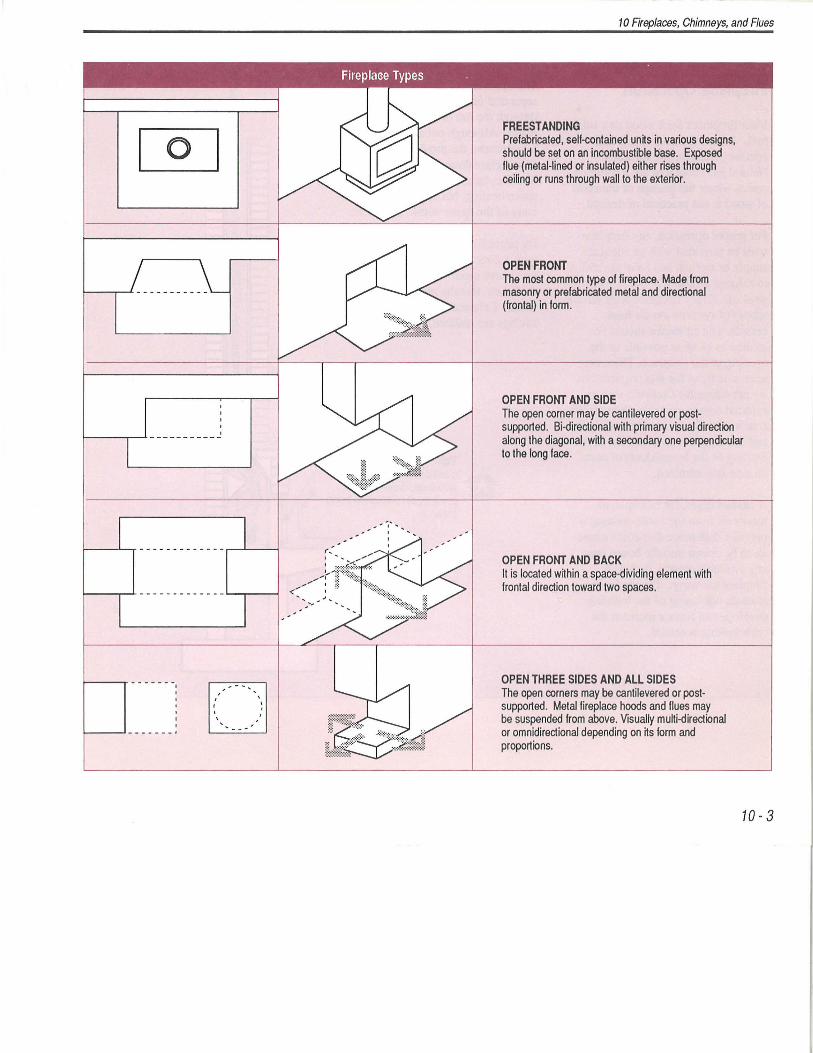
FREEST ANDING Prefabricated, self-contained units in various designs, should be set on an incombustible base. Exposed flue (metal-lined or insulated) either rises through ceiling or runs through wall to the exterior.
OPEN FRONT The most common type of fireplace. Made from masonry or prefabricated metal and directional (frontal) in form.
OPEN FRONT AND SIDE The open corner may be cantilevered or postsupported. Bi-directional with primary visual direction along the diagonal, with a secondary one perpendicular to the long face.
OPEN FRONT AND BACK It is located within a space-dividing element with frontal direction toward two spaces.
OPEN THREE SIDES AND All SIDES The open corners may be cantilevered or postsupported. Metal fireplace hoods and flues may be suspended from above. Visually multi-directional or omnidirectional depending on its form and proportions.
10-3

10 Fireplaces, Chimneys, and Flues
Fireplace Operation
Most fireplaces burn wood as a solid fuel. Some bum natural gas and operate similar to gas furnaces. Natural gas fireplaces are a common option where the storage or transport of wood is not practical or desired.
For proper operation, any fireplace must be provided with an adequate supply of oxygen and have the ability to exhaust a variety of combustion byproducts. Every fireplace must have a supply of combustion air from outside. The air intake should be located as close as possible to the opening of the fireplace. There are several reasons for this requirement. By providing the fireplace with an external source of combustion air the competition for inside air is reduced and therefore the potential for backdrafting of the by-products of combustion is minimized.
A clothes dryer, for example, exhausts air from the home creating a pressure difference that could cause air to be drawn into the house from any available source, such as a fireplace chimney. The tendency towards tightening of the building envelope can further increase the backdrafting potential.
10-4
The operation of the fireplace can be separated further from the house through the use of tight fitting glass doors. Although not a specific Code requirement, the provision of tight fitting glass doors is recommended. The fireplace continues to provide space heating, but operates independently of the space within the home.
By providing the combustion chamber with a direct source of combustion air less warm inside air is exhausted out ~f the house, thereby reducing energy waste. Enhanced safety and cost savings are realized.
Tight fitting pyroceramic glass doors prevent house air from being drawn out and products of combustion being drawn in
External source of combustion air

1 0.1.1 General Requirements
Footings must be provided under all masonry or concrete fireplaces and must rest on undisturbed soil, rock, or compacted granular fill. The size of the footing will be deterinined by the size of the fireplace, whether or not the
Noncombustible hood to direct air away from fire and to prevent entry of flaming embers (9.22.1.4)
Tight fitting damper w~h control that indicates position of damper -operable from room containing fireplace
Supply air duct minimum 100 mm (4') diameter or equivalent area non combustible and corrosion resistant
Figure 1 0.1.2 a Air Intake Requ irements
chimney is supported, whether the fireplace provides support to structural elements of the building, and the bearing capacity of the soil. A footing is required to be at least 100 mm (4") thick and its projection must not be greater than the thickness unless it is reinforced. Chapter 2, Foundations, provides more details.
Air supply located at front centre of fire chamber
50 mm (2')
Minimum 50 mm (2') clearance from combustible material for min. 1.0 m (3' 3') away from outlet to fire chamber 25 mm ( 1') clearance for the remainder of the duct 2!1IY. if intake is above the hearth
10 Fireplaces, Chimneys, and Flues
1 0.1.2 Combustion Air for Fireplaces
All fireplaces must be provided with an outside air source for the combustion of fuel. The requirements for this air intake duct are outlined in Figure 1 0.1.2 (a). Clearance from combustible material of 50 mm (2") is required from the outlet in the fireplace for 1m (3' 3") along the intake supply duct.
Note that the 25 mm (1 ") clearance to combustible material for the remainder of the supply duct only applies if the intake vent is higher than the outlet in the fireplace. The exterior intake must prevent the entry of rain, direct wind, snow, insects and fallen leaves and be constructed with a non-corrosive material.
Factory-built fireplaces are required to have external combustion air and must be installed according to the requirements in 1 0.1.6 of this Guide.
The Housing Code provisions for fireplace inserts are outlined in 10.1. 7 of this Guide.
10-5

10 Fireplaces, Chimneys, and Flues
1 0.1.3 Clearance of Masonry Fireplaces to Combustibles
The clearance of a fireplace to combustible framing must conform to Figure 10.1.3 (a). Interior wall framing must have 100 mm (4") of clearance from a fireplace while exterior wall framing must have at least 50 mm (2") clearance. The clearance from the smoke chamber to interior wall framing can be no less than 50 mm (2") and 25 mm (1 ") to exterior wall framing.
It is very important that the exposure of combustible material is kept at a safe distance from the opening of a fireplace. Figure 10.1.3 (b) illustrates the required clearances. Combustible materials must not be placed within 150 mm (6") of the fireplace opening or heat circulating vent. If the combustible material projects more than 38 mm (1-1/2") from the face of the fireplace, the clearance of the combustible material must be doubled to 300 mm (12"). Combustible material requires at least 50 mm (2") of clearance from metal that penetrates from inside out to the face of the fireplace such as a damper control.
10- 6
EXTERIOR WALL
Clearance of combustible framing below smoke chamber on exterior wall min 50 mm (2") (9 .22.9.3(1 )) Figure 1 0.1.3 a Clearance of a Fireplace to Combustible Framing
Clearance to the fireplace opening or above heat circulatin-.--.~1...1 duct openings:
min 300 mm (12") if combustible projection is • more than 38 mm (1-1/2") beyond face of fireplace or 150 mm (6") if combustible projection is 38 mm (1 1 !2") or less (9.22.9.1) (9.22.9.4)
Figure 10.1.3 b
... . . ...
INTERIOR WALL
Clearance of combustible framing above smoke chamber on interior wall min 50 mm (2")
1-=-"<r/1.- (9.22.9.3.(2))
Steel stud spacer
of combustible framing smoke chamber on interior
wall min 100 mm (4") (9.22.9.3.(1))
Note :
Metal exposed to the interior of a fireplace such as the damper control shall have a min 50 mm (2") clearance from any combustible
aterial on the face of fireplace
.22.9.2)
Projections are measured from finished fireplace openings
Clearance of Combustible Material from Fireplace Opening

Figure 1 0.1.4 a
Warm air outlet
' '
' ' ' ' ' I , ' I
-- r -4------ - - - ---- --- - - -- · - ~- -~---- · -: ; -- --- - ~
-, ' I ' '
- J
Cold air intake
' '
r -I I
' ·' '-
Steel Liner With Air Circulation Chamber (9.22.2.3)
non·combustible hearth
~=-1 ~!~ tM
min. 200 mm (8') J Figure 10.1.5 a Hearth Extension
E E
§
(9.22.5.1)
10 Fireplaces, Chimneys, and Flues
1 0.1.4 Fireplace Liners
A fireplace must have at least 50 mm (2") thick firebrick around the sides and the back and at least 25 mm (1") on the floor. Firebricks are required to be laid with high temperature cement mortar that complies with CGSB 10-GP-3Ma, "Refractory Mortar, Air Setting." The joints between firebricks must be offset from the surrounding masonry in the fireplace.
Fireplaces can also be lined with steel , provided that manufacturing and installation complies with CANIULCS639-M87, "Standard for Steel Liner Assemblies for Solid-Fuel Burning Masonry Fireplaces." Figure 10.1.4 (a) shows a steel liner with an air circulation chamber incorporated into it.
1 0.1.5 Masonry and Concrete Hearths
A fireplace must have its hearth, the floor of the fireplace, extend out beyond the face of the fireplace at least 400 mm (16") horizontally and 200 mm (8") to either side vertically. The extension of the hearth must be noncombustible. Refer to Figure 10.1.5 (a).
10- 7

10 Fireplaces, Chimneys, and Flues
The hearth of the fireplace may step up from the hearth extension provided that the width of the hearth is increased 50 mm (2") for rises between 150 mm (6") and 300 mm (12"). Where the fireplace hearth is more than 300 mm (1 2") above the hearth extension, the width of the hearth must increase 25 mm (1 ") for every 50 mm (2") the fireplace extends higher than the 300 mm (1 2") limit. Refer to Figure 10.1.5 (b).
The support of a hearth for a fireplace must be with at least 140 mm (5.5") of solid masonry forming a trimmer arch or at least 100 mm (4") of reinforced concrete forming a trimmer not including the thickness of the hearth itself. Provided that a fireplace opening is at least 200 mm (8") above the floor level, the hearth extension may rest on the combustible floor framing. Refer to Figure 10.1.5 (b) .
10-8
Framing and lormwork instal led beneath the hearth
lor forming purposes should be removed
II v
Reinforcing bar
450 mm (18') \ 300 mm (12')
, . . . .
· ~ I I
~ I~(
Provided that the fireplace __. ~
~~ open ing is at least 200 mm (8') above the floor level,
the hearth e~ension may r~st on the combustible floor lram1ng
( 9.22.5.2 (2))
Figure 10.1.5 b Hearth Dimension and Support
v ~ e R 1nforc1ng bar
Where the hearth is elevated more than 150 mm (5-7/8') above the hearth extension, the width of the hearth extension must be increased by -50 mm (2') lor an elevation between 150 mm (5-7/8') and 300 mm (12') and -an additional 25mm (1') lor every 50 mm (2' ) in elevation above 300 mm (12') (9.22.5.1 (2))
(9.22.5.2)
Exterior
Minimum 140 mm (5-112"
I I
I I
Exterior
Minimum 140 mm (5-112"
Figure 10.1.5 c Fireplace Liner
I
I
I
I
I I
Interior
Exterior sides minimum 140 (5-1/2")
Interior
minimum 190 mm ( 7-112')T Exterior sides minimum 140 (5-1/2")
Minimum 190 mm (7-112")
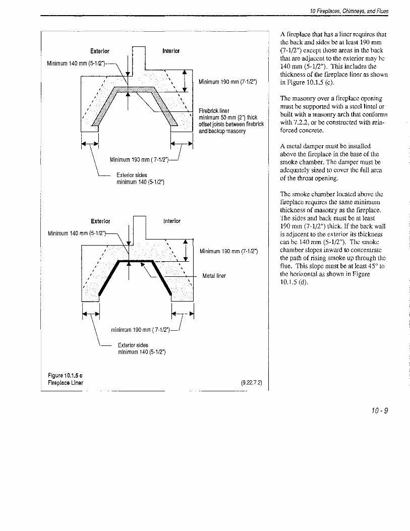
Firebrick liner minimum 50 mm (2") thick offset joints between firebrick and backup masonry
Minimum 190 mm (7-112")
Metal liner
(9.22.7.2)
10 Fireplaces, Chimneys, and Flues
A fireplace that has a liner requires that the back and sides be at least 190 mm (7 -1/2") except those areas in the back that are adjacent to the exterior may be 140 mm (5-1/2"). This includes the thickness of the fireplace liner as shown in Figure 10.1.5 (c).
The masonry over a fireplace opening must be supported with a steel lintel or built with a masonry arch that conforms with 7.2.2, or be constructed with reinforced concrete.
A metal damper must be installed above the fireplace in the base of the smoke chamber. The damper must be adequately sized to cover the full area of the throat opening.
The smoke chamber located above the fireplace requires the same minimum thickness of masonry as the fireplace. The sides and back must be at least 190 mm (7 -1/2") thick. If the back wall is adjacent to the exterior its thickness can be 140 mm (5-1/2"). The smoke chamber slopes inward to concentrate the path of rising smoke up through the flue. This slope must be at least 45° to the horizontal as shown in Figure 10.1.5 (d).
10-9

10 Fireplaces, Chimneys, and Flues
Flue should be centered to avoid uneven drafts
Smoke chamber: front back and sides should be smooth to minimize drag
Allow for expansion :' at damper ends :
'
'
' ' '
' '
' '
,' ,r - - - - - - - - - - - - - - - - -
' ------- ----------' . .
Figure 10.1.5 d Smoke Chamber
10 - 10
' ' ' ' ' ' '
' ' ' '
' ' ' -- - - - - - - . ~ - .,).
' '
' '
Smoke-tight walls
25 mm (1 ' ) clearance between wood and the sides of the smoke chamber
Minimum 45°
12 mm (112') offset recommended for better efficiency
"'Q Parging
Smoke chamber Throat 50 mm (2') firebrick ( 9.22.2.1)
Stagger firebrick and backup masonary joints ( 9.22.2.2)
Minimum 25 mm (1') firebrick on floor
( 9.22.2.1) Q:::.::;:::::::::.::;:::::::::.::;::::::~dn~~=t::!~~
Section through fireplace
(9.22.7.1)

1 0.1.6 Factory-Built Fireplaces
The installation of factory-built fireplaces must comply with CAN/ULC S?10-M87, "Standard for Factory-Built Frreplaces." Some general requirements include: all prefabricated frreplaces must have prefabricated chimneys which are specifically tested for use with the fireplace; installation instructions provided by the manufacturer must accompany the fireplace; all parts and components must be made of non-c.ombustible material; only factory supphed hardware is to be used for
Have a direct sealed connection to the chimney flue, or extend the entire height of the chimney w~h a listed chimney liner, or have a direct sealed connection to smoke chamber with a clean-out or have provisions for removal fo'r cleaning flue and smoke chamber
Extend hearth using min. 10 mm (3/8' ) thick non-combustible material to compensate for the insert protruding in front of fireplace facing
Figure 10.1.7 a Fireplace Inserts
installation; and on-site cutting and make-fitting is strictly prohibited.
Other provisions include requirements for unit assembly, joints, frre stop spacers , supports, radiation shields, flue dampers, caps, roof assemblies, frre screens, hearth assembly, combustion air, and doors. A prefabricated frreplace does not necessarily have to be enclosed in masonry. Tile or gypsum finishes may also be used.
If a factory-built frreplace is installed in the basement ensure it is certified for this type of installation.
This is a preferred method of instalation. Other methods are allowed by the code
Flue collar sealing plate
Metal connecting flue collar Shroud
Metal liner, firebrick or other masonry must not be removed to accommodate the insert
* Insert must not be installed in a factory built fireplace
(9.22.10.1)
10 Fireplaces, Chimneys, and Flues
1 0.1.7 Fireplace Inserts
Fireplace inserts are required to be installed in conformance with CAN/ CSA-B365-M87, "Installation Code for Solid Fuel Burning Appliance and Equipment." A frreplace insert may only be installed in a frreplace that has at least 190 mm (7 -1{2 ") of solid masonry between the smoke chamber and any combustible materials unless the insert is designed and listed for lower clearances.
Inserts that are not designed for rem~val f?r cleaning must have a factory bmlt chimney liner installed from the throat of the insert to the top of the chimney, a completely sealed connection between the chimney flue and insert, or a direct sealed connection to the smoke chamber with a cleanout to any part of the smoke chamber that is inaccessible. Refer to Figure 10.1.7 (a) for other details.
10- 11

10 Fireplaces, Chimneys, and Flues
10.2 CHIMNEYS AND FLUES
Chimneys are used to exhaust the byproducts from the combustion of a fuel such as oil, gas, or wood. The chimney, by definition is the entire structure provided to allow the exhaust of unwanted fumes or smoke. The liner is the inner surface of a chimney exposed to the exhausted by-products. The passage through which these fumes or smoke travel is referred to as a flue.
The requirements for fire safety and health that follow must be strictly adhered to. The requirements for the exhaust of smoke from fireplaces as well as other appliances within the scope of the Housing Guide are detailed in this section. Chapter 12 of this Guide identifies other appliances that require chimneys.
Gas fired appliances must be designed and installed according to specific applicable standards. Local gas utilities can provide more information.
10 - 12
1 0.2.1 General Requirements
The scope of this Guide is limited to chimneys that are no greater than 12 m (39') in height, constructed of masonry or concrete, and that serve fireplaces or appliances having a total combined output of 120 kW or less. Flue pipes for appliances such as stoves, ranges, prefabricated fireplaces, and space heaters are governed by CAN/CSAB365-M87, "Installation Code for Solid-Fuel Burning Appliances and Equipment."
As noted earlier, all prefabricated fireplaces require factory-built chimneys. The installation of these chimneys is regulated by CAN/ULC-S629-M87, "Standard for 650 °C Factory-Built Chimneys".
A flue must be constructed completely air tight so as to prevent any smoke, burning embers, or flames from escaping and creating a fire hazard.
Additional chimney requirements are found in the corresponding section of the Housing Code and in Section 1.5.
1 0.2.2 Clearance of Chimneys and Flues to Combustibles
Clean out openings for fireplaces require a minimum clearance of 150 mm (6") from combustible material.
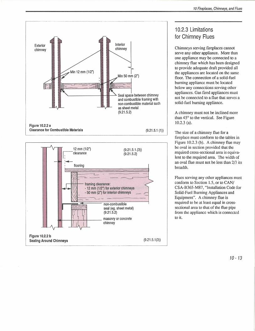
Clearance of combustible materials from chimneys is required as shown in Figure 10.2.2 (a). A minimum of 50 mm (2") of clearance is required for interior chimneys and 12 mm (1/2") clearance for exterior chimneys.
Flooring materials require a minimum clearance of at least 12 mm (1/2") from chimneys as shown in Figure 10.2.2 (b). All spaces created from these clearances must be sealed at the top or bottom as shown in Figure 10.2.2 (b) with a non-combustible material. This seal must be air tight to prevent the passage of smoke. Sheet metal is a suitable material for this purpose.
Joists and beams can be supported by masonry walls that enclose chimneys if combustible framing is separated by at least 290 mm ( 11-1/2 ") of solid masonry.
Exterior chimney
Figure 10.2.2 a
(2")
'---------11---111-~ Seal space between chimney and combustible framing with non-combustible material such as sheet metal (9.21.5.2)
Clearance for Combustible Materials (9.21.5.1 (1))
12 mm (112") ~clearance
:-flooring
r-I!Hrt-.J-- framing clearance:
(9.21.5.1 .(3)) (9.21.5.2)
- 12 mm (112") for exterior chimneys -50 mm (2") for interior chimneys _ .s-
non-combustible seal (eg. sheet metal) (9.21.5.2)
~f..--r-1....--+--+-~-- masonry or concrete chimney
Figure 1 0.2.2 b Sealing Around Chimneys (9.21 .5.1(3))
10 Fireplaces, Chimneys, and Flues
1 0.2.3 Limitations for Chimney Flues
Chimneys serving fireplaces cannot serve any other appliance. More than one appliance may be connected to a chimney flue which has been designed to provide adequate draft provided all the appliances are located on the same floor. The connection of a solid-fuel burning appliance must be located below any connections serving other appliances. Gas fired appliances must not be connected to a flue that serves a solid-fuel burning appliance.
A chimney must not be inclined more than 45° to the vertical. See Figure 10.2.3 (a).
The size of a chimney flue for a fireplace must conform to the tables in Figure 10.2.3 (b). A chimney flue may be oval in section provided that the required cross-sectional area is equivalent to the required area. The width of an oval flue must not be less than 2/3 its breadth.
Flues serving any other appliances must conform to Section 1.5, or to CAN/ CSA-B365-M87, "Installation Code for Solid-Fuel Burning Appliances and Equipment". A chimney flue is required to be at least equal in crosssectional area to that of the flue pipe from the appliance which is connected to it.
10- 13

10 Fireplaces, Chimneys, and Flues
' Nominal Rectangular Flue Sizes for Fireplace Chimneys '
Maximum FirEfplace Chimney Height in metres (ft) Opening m2 (ft2) 3.0 4.6
0.15 (1.6) 200 X 200 (8 X 8) 200 X 200 (8 X 8)
0.25 (2.7) 200 X 300 (8 X 12) 200 X 300 (8 X 12)
0.35 (3.8) 200 X 300 (8 X 12) 200 X 300 (8 X 12)
0.50 (5.4) 300 X 300 (12 X 12) 300 X 300 (12 X 12)
0.65 (7.0) 300 X 400 (12 X 16) 300 X 400 (12 X 16)
0.80 (8.6) 400 X 400 (16 X 16) 300 X 400 (12 X 16)
1.0 (10.8) 400 X 400 (16 X 16) 400 X 400 (16 X 16)
1.2 (12.0) - 400 X 400 (16 X 16)
6.0 9.0
c 0.1 5 (1 .6) 200 X 200 (B x B) 200 X 200 (B X B)
0.25 (2.7) 200 X 300 (B X 12) 200 X 300 (B X 12)
0.35 (3.8) 200 X 300 (B X 12) 200 X 300 (8 X 12)
0.50 (5.4) 300 X 300 (12 X 12) 300 X 300 (12 X 12)
0.65 (7.0) 300 X 400 (12 X 16) 300 X 400 (12 X 16)
0.80 (8.6) 300 X 400 (12 X 16) 300 X 400 (12 X 16)
1.0 (10.8) 300 X 400 (12 X 16) 300 X 400 (12 X 16)
Figure 1 0.2.3 a 1.2 (12.0) 400 X 400 (16 X 16) 300 X 400 (12 X 16) Inclination of Chimney Flues (9.21 .2.3)
1.4 (15.0) 400 X 400 (16 X 16) 400 X 400 (16 X 16)
1.6 (17.2) - 400 X 400 (16 X 16)
Figure 10.2.3 b Flue Sizes for Fireplace Chimneys (9.21.2.5)
10- 14

Figure 1 0.2.4 a Flue Liner
Chimney liner installed when surrounding masonry is installed
If this dimension is less than 190 mm ( 7-1/2')
~~1------ then this space shall not be filled with mortar (9.21.3.8(1))
1-------- Mortar on butt ends of chimney liner 1 part portland cement to 3 parts sand
~_Lli.L_L_.a__ ___ and struck flush ( 9.21.3.2(2))
10 Fireplaces, Chimneys, and Flues
1 0.2.4 Chimney Liners
A chimney constructed of masonry or concrete must be lined with either concrete, clay, firebrick, or metal. The lining must be installed at the same time of chimney construction.
The joints of linings must be sealed to prevent any escape of smoke, fumes, or condensate into the assembly of the chimney. The mortar joints of clay or firebrick liners must be struck flush to make a smooth continuous surface that will reduce the build-up of soot on the liner.
Concrete liners must conform to Clause 4.2.6.4 of CAN/CSA-A405, "Design and Construction of Masonry Chimney and Fireplaces", as shown.
Clay liners must comply with ASTM C315, "Clay Flue Linings", be at least 15.9 mm (5/8") thick, and be able to resist softening, splitting, or cracking at temperatures up to 1100 °C.
Firebrick liners must comply with ASTM C27, "Classification of Fireclay and High Alumina Refractory Brick" and mortar for these liners must comply with CGSB 10-GP-3Ma, "Refractory Mortar, Air Setting."
A space of not less than 10 mm (3/8") is required between the liner and the chimney walls. This space may be filled with mortar provided that the chimney walls are at least 190 mm (7-1/2") thick masonry. Refer to Figure 10.2.4 (a).
10. 15

10 Fireplaces, Chimneys, and Flues
Chimney liners used for solid-fuel, gas, or oil burning appliances must be butted using mortar consisting of 1 part Portland cement to 3 parts sand by volume. Chimney liners used for solidfuel appliances may optionally use mortar that conforms with CGSB 10-GP-3Ma, "Refractory Mortar, Air Setting."
A chimney liner is required to extend at least 200 mm (8") below the lowest flue pipe connected to it. The liner is also required to extend at least 50 mm (2") and not more than 100 mm (4") above the chimney cap. Refer to Figure 10.2.4 (b).
10- 16
Figure 1 0.2.4 b Chimney Liner Extensions
.. -t-. ··~
Extend liner above chimney cap minimum 50 mm (2') maximum 100 mm (4')
Chimney cap
Chimney liner
Thimble
Lowest flue pipe ----~ connecting into liner
Chimney liner must extend min. 200 mm ( 7-7/8') below lowest flue pipe
Corbelling
Cleanout w~h tight fitting door
min. 200 mm ±20 mm (min. 8' ± 7/8')

1 0.2.5 Masonry and Concrete Chimneys
The wall thickness of a chimney must be at least 75 mm (3") solid masonry excluding the liner thickness. The separation of flues, where more than one are in a chimney, requires 75 mm (3 ") of masonry or concrete (not including the liner thickness), or at least 90 mm (3.5") of firebrick may be used. Refer to Figure 10.2.5 (a).
A chimney must be in all cases at least 900 mm (3') at least above the highest point that the chimney contacts. Refer to Figure 10.2.5 (b). A chimney must
Figure 1 0.2.5 a
also be not less than 600 mm (2') above any part of the roof that is within 3 m (9'-10") of the chimney. CAN/CSAA405 "Design and Construction of Masonry Fireplaces" discusses the required lateral restraint for chimneys.
A cap that is waterproof and constructed with either reinforced concrete, masonry, or metal must be placed on the top of the chimney . This cap must allow water run-off and provide a drip not less than 25 mm (1 ") from the chimney wall on the underside of the capping projection.
Caps that are cast-in-place concrete only require a sufficient space between the cap and the liner to fill with a bond
Separation of Chimney Flues In the Same Chimney
10 Fireplaces, Chimneys, and Flues
break. Refer to Figure 10.2.5 (c). Caps that are precast concrete or masonry require a space for a bond break as well as flashing which is sealed to the liner and runs out under the cap. Refer to Figure 10.2.5 (d).
A cleanout must be provided for chimneys that do not serve a fireplace. A tight fitting metal door must be provided at the bottom of the chimney. Refer to Figure 10.2.4 (b).
Flashing must be provided to prevent the penetration of water into the chimney and the building envelope.
Rue liners
75 mm ( 3') minimum of masonry or concrete when flue liners are clay 90 mm ( 3-112') minimum firebrick when flue liners are made of firebrick
(9.21 .4.8) (9.21.4.9)
10- 17

10 Fireplaces, Chimneys, and Flues
Figure 10.2.5 b Height of Chimney Flues
10- 18
0
less than 3m (9' 10")
0
( 9.21.4.4)
900 mm (2' 11 ") minimum
0
0
Bracing required when height of chimney is greater than 3.6 m (11' 10") or as required to provide additional lateral stability.
More than one tie is recommended ( 9.21.4.5)

Figure 1 0.2.5 c Cast in Place Chimney Cap
Flue liner
Bond break
Slope away from liner
14---- Cast in place concrete chimney cap
Minimum 25 mm ( 1') drip projection
Chimney wall
Flue liner ---------111.
Bond break
Slope away from liner
Jointed precast concrete or masonry chimney cap
Figure 1 0.2.5 d
Metal flashing (9.21.4.10)
Minimum 25 mm ( 1') _ ____..__-J&.<'-,L,.L/ drip projection
Precast Concrete or Masonry Chimney Cap
(9.21.4.5)
(9.21.4.5)
10 Fireplaces, Chimneys, and Flues
From CAN/CSA·A405 "Design and Construction of Masonry Fireplaces"
A chimney constructed with Type N mortar can rise 3.6 m (11' 10") from the highest point of lateral support provided that the smallest dimension is at least 400 mm (16").
The number of flues that are contained within a chimney does not influence height requirements.
The height shall be taken from the last point of lateral support for the chimney. On frame construction of interior chimneys, the height measurement is taken from the bottom of the lowest flue liner. In solid or brick veneer construction, the height measurement is taken from the point where the chimney stack leaves the masonry which forms part of the exterior. The portion of the. chimney stack above the roof shall be considered as free standing.
10- 19
10 Fireplaces, Chimneys, and Flues
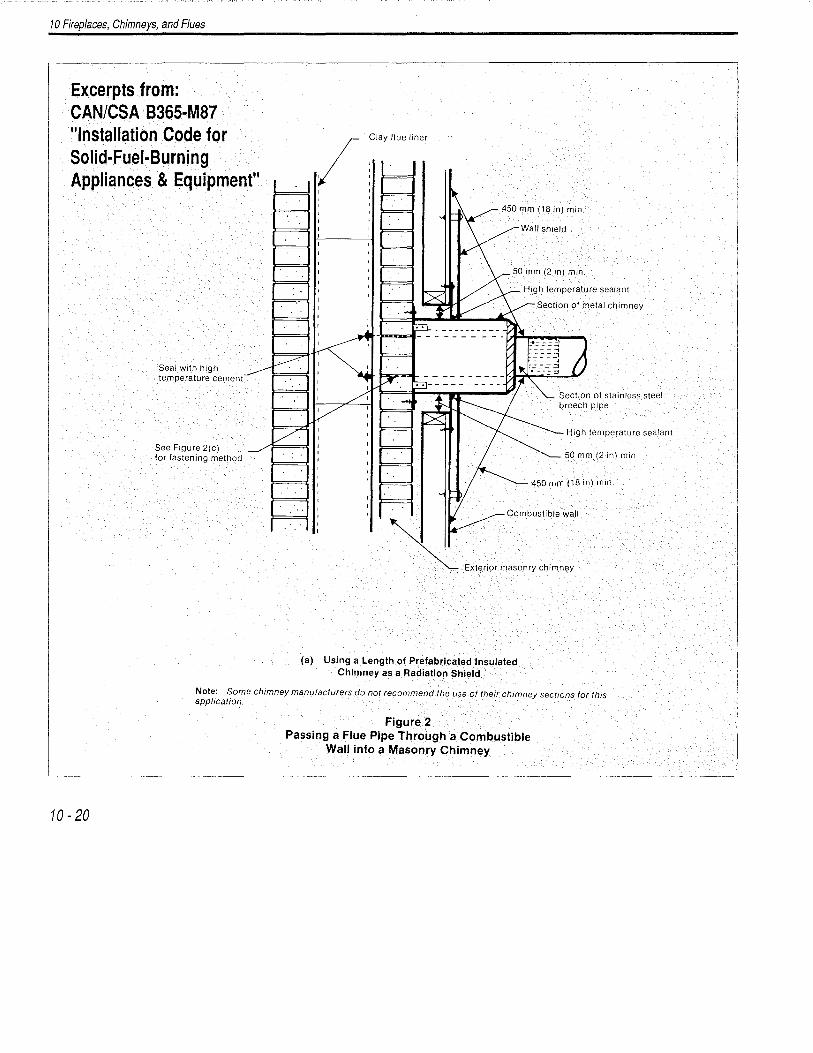
Excerpts from: CAN/CSA 8365-M87 "Installation Code for Solid-Fuel-Burning Appliances & Equipment"
Seal with high temperature cement
See Figure 2(c) for fastening method
Clay flue liner
Wall shield
High temperature sealant
450 mm (18 in) min.
Combustible wall
Exterior masonry chimney
(a) Using a Length of Prefabricated Insulated Chimney as a Radiation Shield
Note: Some chimney manufacturers do not recommend the use of their chimney sect10ns for this application.
10-20
Figure 2 Passing a Flue Pipe Through a Combustible
Wall into a Masonry Chimney

10 Fireplaces, Chimneys, and Flues
air space
Metal radiation shield
Mechanical fastening
Clay flue thimble
Stainless steel breech pipe
Flue pipe
600 mm (18 in) min.
25 mm (1 in) min. air space
(b) Using a Clay Thimble
Outward protrusions to provide mechanical fastening
Section of stainless steel breech pipe
Refractory cement
(c) Using a Mechanically Fastened Breech Pipe (No Thimble Required)
Note: Protection of combustible construction not shown.
Figure 2 (Concluded)
10-21

10 Fireplaces, Chimneys, and Flues
10-22
Hole in wall sized to clear sheet metal. sleeve.
Ceiling Sheet metal (or other noncombustrble -"--<--<'--'.'li-''-";,"-<--'-'--'7""
material) cover on one side only. t~ If cover is also used on the ::-.. other srde, the sleeve must protrude .:!:> $' :r through it. '-- E
li t{ E~
$ 1225 m'm ~~ I' (9 rn) l
0
I "' 25 mm
(1 in)
Sheet metal sleeve (supported on one end, open on both ends) with a diameter that provides 225 mm (9 in) of clearance to combustibles all around the flue pipe and a length that provides 450 mm (18 in) flue pipe to wall.
/1 25 mm (1 in)
450mm (18 in)
(b) Flue Pipe Installation Through an Interior Wall of Combustible Material-0.33 mm (0.013 in) Sheet Metal Protection
Ceiling <f)
"' //////////////1 (j)
Sheet metal (or other noncombustible material) covers on each side of the wall. (Spacers shown only to provide more stable support of factory-built chimney section.) \'0\1'\
"'' ~<§l"'
Length of factory-built chimney. (Sheet metal covers would be of equal size if chimney was centred in the wall.)
Chimney sections used should be of the solid-pack, insulated type having metal caps factory installed at each end, and of a type certified for 50 mm (2 in) clearance to combustible material.
c ::J
-'" c '" ·-(f) a)-
Flue pipe
(c) Flue Pipe Installation Through an Interior Wall of Combustible Material Using a Length of Prefabricated Insulated Chimney as a Radiation Shield Note: Some chimney manufacturers do not recommend the use of their chimney sections for this application.
Figure 1 Methods of Passing a Flue Pipe
Through an Interior Wall of Combustible Material