Fire Suppression by Water Spray
52
Fire suppression by water sprays G. Grant a,1 , J. Brenton b,1 , D. Drysdale c, * a Grant Fire Consultants Ltd, 42 Bonaly Road, Edinburgh EH13 0EQ, UK b Institute of Physics Publishing, Dirac House, Temple Back, Bristol BS1 6BE, UK c Department of Civil and Environmental Engineering, The University of Edinburgh, The King’s Buildings, Edinburgh EH9 3JN, UK Abstract Water has become the most widely used fire-fighting agent because its fire suppression performance is hard to beat. The thermal characteristics of water make it ideally suitable as an extinguishing agent for most types of fire, whether it is used to extract heat directly from the flames, the hot products of combustion or from the surface of the fuel. The phase change from liquid water to water vapour (steam) is particularly effective in extracting thermal energy and the production of large quantities of water vapour may further contribute to fire extinguishment by reducing the oxygen concentration of the surrounding atmosphere, particularly where the fire is confined. The present paper is based on an extensive literature review conducted within Edinburgh University’s Fire Safety Engineering Group and sponsored by the UK Home Office Fire Research and Development Group. The aim of the research project was to establish the current state-of-the-art regarding the use of water sprays for the suppression and extinguishment of typical (Class ‘A’) compartment fires and to identify where gaps exist in the current knowledge. q 2000 Elsevier Science Ltd. All rights reserved. Keywords: Water; Spray; Fire; Suppression; Extinguishment; Droplets Contents 1. Introduction .................................................................. 80 2. Classification of fire types ........................................................ 82 3. The Class ‘A’ fire—characteristics ................................................. 83 3.1. Heat transfer aspects ....................................................... 83 3.2. Mechanisms of flame spread in Class ‘A’ fires .................................... 83 3.3. Pre-flashover compartment fires ............................................... 83 3.4. Post-flashover compartment fires .............................................. 84 3.5. Unconfined Class ‘A’ fires ................................................... 84 4. Class ‘A’ fire extinguishment by water .............................................. 85 5. Quantitative characterisation of water sprays .......................................... 86 5.1. General ................................................................. 86 5.2. Definition of droplet mean diameter ............................................ 86 5.3. Sample size and standard distributions .......................................... 87 5.4. Practical methods for measuring drop size distribution ............................... 87 5.5. Determination of spray pattern ................................................ 88 6. Modes of application of fire-fighting water ............................................ 88 6.1. Solid jets ................................................................ 88 6.1.1. Origins of jet instability ............................................... 88 Progress in Energy and Combustion Science 26 (2000) 79–130 PERGAMON www.elsevier.com/locate/pecs 0360-1285/00/$ - see front matter q 2000 Elsevier Science Ltd. All rights reserved. PII: S0360-1285(99)00012-X * Corresponding author. 1 Formerly at: Department of Civil and Environment Engineering, The University of Edinburgh, Edinburgh EH9 3JN, UK.
description
FIRE SAFETY
Transcript of Fire Suppression by Water Spray

Fire suppression by water sprays
G. Granta,1, J. Brentonb,1, D. Drysdalec,*aGrant Fire Consultants Ltd, 42 Bonaly Road, Edinburgh EH13 0EQ, UK
bInstitute of Physics Publishing, Dirac House, Temple Back, Bristol BS1 6BE, UKcDepartment of Civil and Environmental Engineering, The University of Edinburgh, The King’s Buildings, Edinburgh EH9 3JN, UK
Abstract
Water has become the most widely used fire-fighting agent because its fire suppression performance is hard to beat. Thethermal characteristics of water make it ideally suitable as an extinguishing agent for most types of fire, whether it is used toextract heat directly from the flames, the hot products of combustion or from the surface of the fuel. The phase change fromliquid water to water vapour (steam) is particularly effective in extracting thermal energy and the production of large quantitiesof water vapour may further contribute to fire extinguishment by reducing the oxygen concentration of the surroundingatmosphere, particularly where the fire is confined. The present paper is based on an extensive literature review conductedwithin Edinburgh University’s Fire Safety Engineering Group and sponsored by the UK Home Office Fire Research andDevelopment Group. The aim of the research project was to establish the current state-of-the-art regarding the use of watersprays for the suppression and extinguishment of typical (Class ‘A’) compartment fires and to identify where gaps exist in thecurrent knowledge.q 2000 Elsevier Science Ltd. All rights reserved.
Keywords: Water; Spray; Fire; Suppression; Extinguishment; Droplets
Contents
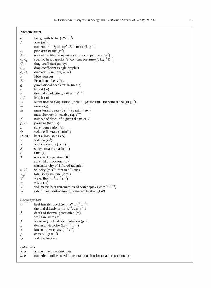
1. Introduction . . . . . . . . . . . . . . . . . . . . . . . . . . . . . . . . . . . . . . . . . . . . . . . . . . . . . . . . . . . . . . . . . . 802. Classification of fire types. . . . . . . . . . . . . . . . . . . . . . . . . . . . . . . . . . . . . . . . . . . . . . . . . . . . . . . . 823. The Class ‘A’ fire—characteristics. . . . . . . . . . . . . . . . . . . . . . . . . . . . . . . . . . . . . . . . . . . . . . . . . 83
3.1. Heat transfer aspects. . . . . . . . . . . . . . . . . . . . . . . . . . . . . . . . . . . . . . . . . . . . . . . . . . . . . . . 833.2. Mechanisms of flame spread in Class ‘A’ fires. . . . . . . . . . . . . . . . . . . . . . . . . . . . . . . . . . . . 833.3. Pre-flashover compartment fires. . . . . . . . . . . . . . . . . . . . . . . . . . . . . . . . . . . . . . . . . . . . . . . 833.4. Post-flashover compartment fires. . . . . . . . . . . . . . . . . . . . . . . . . . . . . . . . . . . . . . . . . . . . . . 843.5. Unconfined Class ‘A’ fires. . . . . . . . . . . . . . . . . . . . . . . . . . . . . . . . . . . . . . . . . . . . . . . . . . . 84
4. Class ‘A’ fire extinguishment by water. . . . . . . . . . . . . . . . . . . . . . . . . . . . . . . . . . . . . . . . . . . . . . 855. Quantitative characterisation of water sprays. . . . . . . . . . . . . . . . . . . . . . . . . . . . . . . . . . . . . . . . . . 86
5.1. General. . . . . . . . . . . . . . . . . . . . . . . . . . . . . . . . . . . . . . . . . . . . . . . . . . . . . . . . . . . . . . . . . 865.2. Definition of droplet mean diameter. . . . . . . . . . . . . . . . . . . . . . . . . . . . . . . . . . . . . . . . . . . . 865.3. Sample size and standard distributions. . . . . . . . . . . . . . . . . . . . . . . . . . . . . . . . . . . . . . . . . . 875.4. Practical methods for measuring drop size distribution. . . . . . . . . . . . . . . . . . . . . . . . . . . . . . . 875.5. Determination of spray pattern. . . . . . . . . . . . . . . . . . . . . . . . . . . . . . . . . . . . . . . . . . . . . . . . 88
6. Modes of application of fire-fighting water. . . . . . . . . . . . . . . . . . . . . . . . . . . . . . . . . . . . . . . . . . . . 886.1. Solid jets. . . . . . . . . . . . . . . . . . . . . . . . . . . . . . . . . . . . . . . . . . . . . . . . . . . . . . . . . . . . . . . . 88
6.1.1. Origins of jet instability . . . . . . . . . . . . . . . . . . . . . . . . . . . . . . . . . . . . . . . . . . . . . . . 88
Progress in Energy and Combustion Science 26 (2000) 79–130PERGAMONwww.elsevier.com/locate/pecs
0360-1285/00/$ - see front matterq 2000 Elsevier Science Ltd. All rights reserved.PII: S0360-1285(99)00012-X
* Corresponding author.1 Formerly at: Department of Civil and Environment Engineering, The University of Edinburgh, Edinburgh EH9 3JN, UK.
6.1.2. Optimum pressure head at the nozzle. . . . . . . . . . . . . . . . . . . . . . . . . . . . . . . . . . . . . . 886.1.3. Height of throw and width of spread. . . . . . . . . . . . . . . . . . . . . . . . . . . . . . . . . . . . . . 88
6.2. Diffuse jets . . . . . . . . . . . . . . . . . . . . . . . . . . . . . . . . . . . . . . . . . . . . . . . . . . . . . . . . . . . . . . 886.2.1. Early use of sprays in fire-fighting. . . . . . . . . . . . . . . . . . . . . . . . . . . . . . . . . . . . . . . . 886.2.2. Definition of sprays. . . . . . . . . . . . . . . . . . . . . . . . . . . . . . . . . . . . . . . . . . . . . . . . . . 896.2.3. Methods of spray production. . . . . . . . . . . . . . . . . . . . . . . . . . . . . . . . . . . . . . . . . . . . 89
6.3. Water mist systems. . . . . . . . . . . . . . . . . . . . . . . . . . . . . . . . . . . . . . . . . . . . . . . . . . . . . . . . 896.3.1. General . . . . . . . . . . . . . . . . . . . . . . . . . . . . . . . . . . . . . . . . . . . . . . . . . . . . . . . . . . . 896.3.2. Definitions of water mist. . . . . . . . . . . . . . . . . . . . . . . . . . . . . . . . . . . . . . . . . . . . . . . 906.3.3. Design of water mist nozzles. . . . . . . . . . . . . . . . . . . . . . . . . . . . . . . . . . . . . . . . . . . . 91
6.3.3.1. Single-fluid mist nozzles. . . . . . . . . . . . . . . . . . . . . . . . . . . . . . . . . . . . . . . 916.3.3.2. Twin-fluid mist nozzles. . . . . . . . . . . . . . . . . . . . . . . . . . . . . . . . . . . . . . . . 91
6.4. Methods of water application used by the fire service. . . . . . . . . . . . . . . . . . . . . . . . . . . . . . . 926.4.1. Jet/spray branches for fire-fighting. . . . . . . . . . . . . . . . . . . . . . . . . . . . . . . . . . . . . . . . 926.4.2. High and low pressure hosereel systems. . . . . . . . . . . . . . . . . . . . . . . . . . . . . . . . . . . 92
7. Desirable droplet characteristics for fire-fighting. . . . . . . . . . . . . . . . . . . . . . . . . . . . . . . . . . . . . . . . 927.1. Spray cooling of gaseous combustion products. . . . . . . . . . . . . . . . . . . . . . . . . . . . . . . . . . . . 927.2. Spray cooling of solid fuel surfaces. . . . . . . . . . . . . . . . . . . . . . . . . . . . . . . . . . . . . . . . . . . . 977.3. Attenuation of thermal radiation by water droplets. . . . . . . . . . . . . . . . . . . . . . . . . . . . . . . . . 1027.4. Spray penetration or ‘throw’. . . . . . . . . . . . . . . . . . . . . . . . . . . . . . . . . . . . . . . . . . . . . . . . . . 102
7.4.1. General . . . . . . . . . . . . . . . . . . . . . . . . . . . . . . . . . . . . . . . . . . . . . . . . . . . . . . . . . . . 1027.4.2. Modelling spray penetration into a fire plume. . . . . . . . . . . . . . . . . . . . . . . . . . . . . . . 104
7.5. Concept of ‘optimum’ droplet size. . . . . . . . . . . . . . . . . . . . . . . . . . . . . . . . . . . . . . . . . . . . . 1068. Experimental data on fire suppression/extinguishment. . . . . . . . . . . . . . . . . . . . . . . . . . . . . . . . . . . 108
8.1. General. . . . . . . . . . . . . . . . . . . . . . . . . . . . . . . . . . . . . . . . . . . . . . . . . . . . . . . . . . . . . . . . . 1088.2. Nature of the ‘standard fire’. . . . . . . . . . . . . . . . . . . . . . . . . . . . . . . . . . . . . . . . . . . . . . . . . . 1098.3. Suppression tests on unconfined fires. . . . . . . . . . . . . . . . . . . . . . . . . . . . . . . . . . . . . . . . . . . 1108.4. Suppression tests on compartment fires. . . . . . . . . . . . . . . . . . . . . . . . . . . . . . . . . . . . . . . . . . 1158.5. Fire suppression test data from WMFSS development. . . . . . . . . . . . . . . . . . . . . . . . . . . . . . . 121
9. Summary . . . . . . . . . . . . . . . . . . . . . . . . . . . . . . . . . . . . . . . . . . . . . . . . . . . . . . . . . . . . . . . . . . . . 124Acknowledgements . . . . . . . . . . . . . . . . . . . . . . . . . . . . . . . . . . . . . . . . . . . . . . . . . . . . . . . . . . . . . . . 126References. . . . . . . . . . . . . . . . . . . . . . . . . . . . . . . . . . . . . . . . . . . . . . . . . . . . . . . . . . . . . . . . . . . . . . 126Glossary of selected terms. . . . . . . . . . . . . . . . . . . . . . . . . . . . . . . . . . . . . . . . . . . . . . . . . . . . . . . . . . . 129
1. Introduction
The UK Home Office Fire Research and DevelopmentGroup (FRDG) has several responsibilities to British FireBrigades, including the assessment of new fire-fighting tech-niques, the publication of technical reports and the develop-ment of training material. One topic of continuing interest tothe FRDG is the use of water sprays to suppress and extin-guish compartment fires of the type attended by the FireService on a daily basis. Consequently, the FRDG spon-sored a major research initiative by the University of Edin-burgh entitledA Study of the Science of Fire Suppressionand Extinctionin order to determine the current state-of-the-art of the subject and to identify any gaps in the currentknowledge base.
Two FRDG technical reports have been published to date:a brief review of the actual mechanisms of fire suppression[1] and a more comprehensive analysis of the important rolethat water plays in fire-fighting practice [2]. The literaturereview on which the present paper is based [2] has revealed,
perhaps surprisingly, that although research into fire safetyscience in general has increased greatly since the SecondWorld War, the subject of fire suppression has receivedrelatively little attention. However, this trend has beenreversed over the last few years, due in large measure tothe interest in water mist as a replacement for Halon gasfixed fire protection systems.
The paper begins by considering the various classifica-tions of fire, with particular emphasis on the ‘Class A’ type.The mechanisms by which water may extinguish fires arethen described, followed by a discussion of the characteris-tics of water sprays and how these characteristics can bequantified. The application of fire-fighting water in theform of solid jets, diffuse sprays and mists is then consid-ered, prior to a more in-depth analysis of the desirabledroplet characteristics for fire-fighting and the concept ofan ‘optimum droplet size’. The paper concludes with acomprehensive review of experimental data relating to firesuppression by water for both confined and un-confined firesover a wide range of scales.
G. Grant et al. / Progress in Energy and Combustion Science 26 (2000) 79–13080
G. Grant et al. / Progress in Energy and Combustion Science 26 (2000) 79–130 81
Nomenclature
a fire growth factor (kW s22)A area (m2)
numerator in Spalding’sB-number (J kg21)Af plan area of fire (m2)Av area of ventilation openings in fire compartment (m2)c, Cp specific heat capacity (at constant pressure) (J kg21 K21)CD drag coefficient (spray)CDS drag coefficient (single droplet)d, D diameter (mm, mm, or m)F Flow numberFr Froude numberv2
=gdg gravitational acceleration (m s22)h height (m)k thermal conductivity (W m21 K21)l, L length (m)Lv latent heat of evaporation (‘heat of gasification’ for solid fuels) (kJ g21)m mass (kg)_m mass burning rate (g s21, kg min21 etc.)
mass flowrate in nozzles (kg s21)Ni number of drops of a given diameter,Ip, P pressure (bar, Pa)p spray penetration (m)Q volume flowrate (l min21)_Q; D _Q heat release rate (kW)V volume (m3)R application rate (l s21)S spray surface area (mm2)t time (s)T absolute temperature (K)
spray film thickness (m)transmissivity of infrared radiation
u, U velocity (m s21, mm min21 etc.)Vtot total spray volume (mm3)_V 00 water flux (m3 m22 s21)w width (m)W volumetric heat transmission of water spray (W m23 K21)_W rate of heat abstraction by water application (kW)
Greek symbolsa heat transfer coefficient (W m22 K21)
thermal diffusivity (m2 s21, cm2 s21)d depth of thermal penetration (m)
wall thickness (m)l wavelength of infrared radiation (mm)m dynamic viscosity (kg s21 m21)n kinematic viscosity (m2 s21)r density (kg m23)f volume fraction
Subscriptsa, A ambient, aerodynamic, aira, b numerical indices used in general equation for mean drop diameter
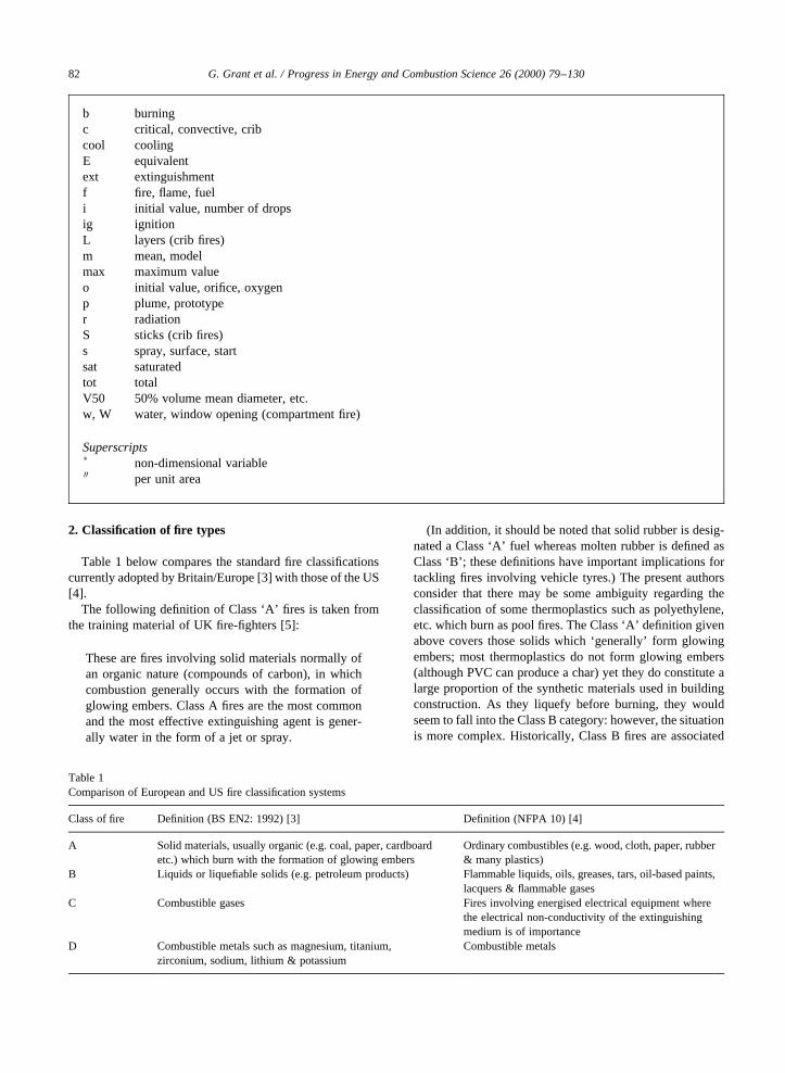
2. Classification of fire types
Table 1 below compares the standard fire classificationscurrently adopted by Britain/Europe [3] with those of the US[4].
The following definition of Class ‘A’ fires is taken fromthe training material of UK fire-fighters [5]:
These are fires involving solid materials normally ofan organic nature (compounds of carbon), in whichcombustion generally occurs with the formation ofglowing embers. Class A fires are the most commonand the most effective extinguishing agent is gener-ally water in the form of a jet or spray.
(In addition, it should be noted that solid rubber is desig-nated a Class ‘A’ fuel whereas molten rubber is defined asClass ‘B’; these definitions have important implications fortackling fires involving vehicle tyres.) The present authorsconsider that there may be some ambiguity regarding theclassification of some thermoplastics such as polyethylene,etc. which burn as pool fires. The Class ‘A’ definition givenabove covers those solids which ‘generally’ form glowingembers; most thermoplastics do not form glowing embers(although PVC can produce a char) yet they do constitute alarge proportion of the synthetic materials used in buildingconstruction. As they liquefy before burning, they wouldseem to fall into the Class B category: however, the situationis more complex. Historically, Class B fires are associated
G. Grant et al. / Progress in Energy and Combustion Science 26 (2000) 79–13082
b burningc critical, convective, cribcool coolingE equivalentext extinguishmentf fire, flame, fueli initial value, number of dropsig ignitionL layers (crib fires)m mean, modelmax maximum valueo initial value, orifice, oxygenp plume, prototyper radiationS sticks (crib fires)s spray, surface, startsat saturatedtot totalV50 50% volume mean diameter, etc.w, W water, window opening (compartment fire)
Superscriptsp non-dimensional variable00 per unit area
Table 1Comparison of European and US fire classification systems
Class of fire Definition (BS EN2: 1992) [3] Definition (NFPA 10) [4]
A Solid materials, usually organic (e.g. coal, paper, cardboardetc.) which burn with the formation of glowing embers
Ordinary combustibles (e.g. wood, cloth, paper, rubber& many plastics)
B Liquids or liquefiable solids (e.g. petroleum products) Flammable liquids, oils, greases, tars, oil-based paints,lacquers & flammable gases
C Combustible gases Fires involving energised electrical equipment wherethe electrical non-conductivity of the extinguishingmedium is of importance
D Combustible metals such as magnesium, titanium,zirconium, sodium, lithium & potassium
Combustible metals
with the most common form of liquid fire: the hydrocarbonpool fire. Hydrocarbons are less dense than water and arenot efficiently cooled by water because of the ease withwhich combustible vapours are released (i.e. they possessa low ‘firepoint’). In contrast, thermoplastics generallyhave firepoints in excess of 2008C, and in some cases3008C, and can be cooled effectively through the applicationof water.
3. The Class ‘A’ fire—characteristics
3.1. Heat transfer aspects
The essential feature of an ‘unwanted fire’ is that the fuelsupply is controlled by the positive feedback of heat fromthe products of its own combustion [6]. The supply ofgaseous volatiles is produced via this feedback of thermalenergy, which is dominated by thermal radiation from turbu-lent diffusion flames when the characteristic fire dimension is.0.3 m [6]. Increasing the rate of evolution of combustionproducts increases the radiative heat feedback, which inturn increases the rate of evolution of volatiles and therebyintensifies the combustion process. This ‘feedback loop’ isultimately self-limiting however, as the flame emissivitycannot exceed unity and thermal radiation absorption occursin the vapour zone above the fuel surface.
Two major differences exist between flammable liquidfires and those involving solid fuels: in solids, both thesurface temperature during burning and the ‘heat of gasifi-cation’ �LV� tend to be significantly greater than those for
liquids [7]. The relatively high surface temperature of burn-ing solids (,400–5008C) in turn leads to significant radia-tive heat losses, while high values ofLV are indicative of theadditional thermal energy required for the chemical decom-position (pyrolysis) of the solid. The formation of a charlayer on the burning surface of wood and some syntheticpolymers initially reduces the heat transfer rate to the in-terior, reducing the pyrolysis rate. Consequently, a greaterexternal heat flux may be required to re-establish a flowrateof volatiles sufficient to sustain combustion. Surfacetemperatures are therefore increased, to maintain therequired flow of heat through the char layer and so theradiative losses will also increase, although surface oxida-tion of the char layer offsets these losses to some degree [7].In confined fires, localised temperatures of,11008C arepossible with corresponding heat flux values as high as200 kW m22.
3.2. Mechanisms of flame spread in Class ‘A’ fires
The possible mechanisms of flame spread and fire growthdepend on the class of fire; solid fuels may be burned in anyorientation, however with liquid fuels the flame is alwayslocated above the horizontal free surface and flame propa-gation is usually horizontal. Williams [8] considered theconcept of ‘fire spread’ to be meaningful only in situationswhere some form of thermal ‘communication’ existsbetween the burning region and the non-burning fuel (e.g.conduction, convection, radiation, or the ejection of flamingembers). Regarding the spread of fire amongst discrete fuelelements, it was noted that thermal conduction is generally
G. Grant et al. / Progress in Energy and Combustion Science 26 (2000) 79–130 83
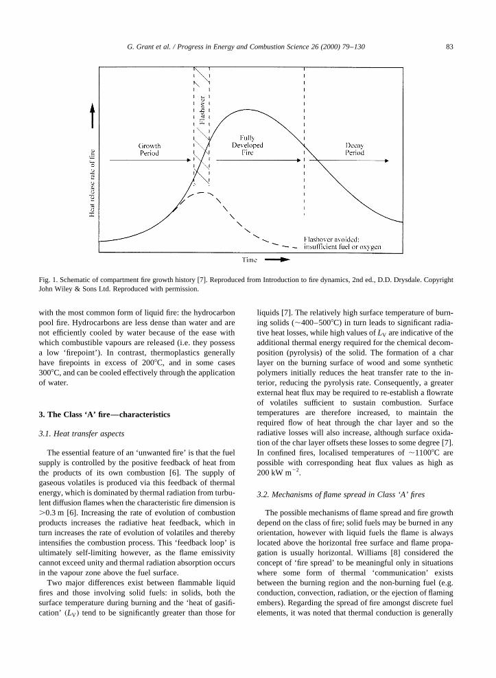
Fig. 1. Schematic of compartment fire growth history [7]. Reproduced from Introduction to fire dynamics, 2nd ed., D.D. Drysdale. CopyrightJohn Wiley & Sons Ltd. Reproduced with permission.

not relevant to item-to-item fire propagation [8]. In this casethe principal mechanisms are radiation, the convection ofhot gases and the expulsion of burning fragments.
3.3. Pre-flashover compartment fires
Compartment fires in domestic or commercial premisesrepresent by far the most common type of fire attended bythe Fire Service. An extensive account of confined firedevelopment in both the ‘pre-flashover’ and ‘post-flashover’regimes has been given by Drysdale [7]. In the context ofClass ‘A’ fire extinguishment, three possible end states havebeen proposed for the compartment environment oncelocalised burning is established [7]:
• The fire may burn itself out without involving other itemsof combustible material, particularly if the item firstignited is in an isolated position.
• If there is inadequate ventilation, the fire may self-extin-guish or continue to burn at a very slow rate dictated bythe availability of oxygen.
• If there is sufficient fuel and ventilation, the fire mayprogress to full room involvement, in which all combus-tible surfaces are burning.
‘Flashover’ is the term given to the relatively abruptchange from a localised and still relatively easily extin-guished fire to the complete involvement of all the combus-tible elements within the compartment. Any occupants whohave not escaped the fire by this stage are unlikely to survive[7].
This sequence of fire development is depicted schemati-cally in Fig. 1, where the periods of growth, full involve-ment and final decay are identified. Here, ‘flashover’ isshown to occur over a finite period of time, which is the
case in reality; although short in relation to the main stagesof the fire history, the flashover period cannot be construedas an instantaneous ‘event’. The lower (dashed) curve illus-trates the course of a hypothetical fire where flashover doesnot occur, either because the available fuel has beenconsumed or through oxygen starvation.
3.4. Post-flashover compartment fires
Post-flashover compartment fires are typified by the totalinvolvement of all combustible surfaces, leading to a maxi-mum heat release rate (HRR) and gas temperatures up to,11008C. This peak, which occurs during the ‘fullydeveloped’ stage and the subsequent ‘decay period’, isshown in Fig. 1. The details of the post-flashover fire historyare dependent upon the quantity and disposition of the fuelelements and the geometry of any ventilation openings.Thus, post-flashover fires may be classed broadly as ‘fuel-controlled’ (no restriction of combustion air supply) or‘ventilation-controlled’ (restricted air supply). In general,fuel-controlled fires tend to be less severe; the presence ofexcess air (i.e. more than is theoretically required forcomplete combustion of the fuel) moderates the compart-ment temperature and is therefore associated with lowerrates of heat release.
3.5. Unconfined Class ‘A’ fires
The behaviour of an unconfined Class ‘A’ fire differs fromthe confined case in several important respects. For openfires, the radiant feedback from solid ‘boundaries’ outwiththe combustion zone and from a smoke layer under theceiling are absent; the mass rate of burning� _m� dependson local heat transfer effects from the flame zone to the
G. Grant et al. / Progress in Energy and Combustion Science 26 (2000) 79–13084
Fig. 2. Thermal energy for heating and phase changes of 1 l of water [10]. Reproduced from O. Herterich, Water as an extinguishing agent(published by Alfred Huthig Publishing Company, Heidelberg, 1960).

fuel bed. For a given fuel load,_m will generally be lowerthan for the equivalent confined case and is fuel-controlled(i.e. the controlling parameter is the fire area,Af and theventilation areaAv is not relevant). ‘Ventilation-controlled’fires in the open are not encountered; however a strong windmay increase the burning rate of fires in the open by indu-cing vigorous turbulent mixing of excess combustion air. Ingeneral, open fires are characterised by a lower smoke andCO production, increased yields of CO2 and water vapourand by lower product temperatures. Thus the combustion ismore efficient (in terms of the chemical conversion ofcarbon) than in the confined case and a given fuel load
will generally burn longer in the open, if unchecked,although the maximum rate of heat release will generallybe lower.
4. Class ‘A’ fire extinguishment by water
The principal action of liquid fire suppressants, such aswater, is the removal of heat from the fire through their heatcapacity and latent heat of vapourisation [9]. Althoughwater may sometimes contribute to fuel dilution (in thecase of water-miscible liquid fuels) or fuel ‘blanketing’
G. Grant et al. / Progress in Energy and Combustion Science 26 (2000) 79–130 85
Fig. 3. Number of droplets and total surface area produced by one litre of water, as monodisperse sprays with various mean droplet diameters,d[10]. Reproduced from O. Herterich, Water as an extinguishing agent (published by Alfred Huthig Publishing Company, Heidelberg, 1960).

(forming a barrier on the fuel surface), in the case of Class‘A’ fires the most important suppression mechanisms are:
• Cooling the fuelsurface, which reduces the pyrolysis rateand so the rate of fuel supply to the flame zone, thusreducing the heat release rate and the radiative feedbackfrom the flame to the fuel surface.
• Cooling the flame zonedirectly, which disrupts thechemical reactions responsible for combustion. Someportion of the heat of reaction is abstracted in heatingand evaporating the liquid water; therefore less thermalenergy is available in the vicinity of the reaction zone.
• Volumetric displacement of the oxidant(oxygen),through the production of (inert) water vapour withinthe combusting environment. This is also known as‘flame smothering’.
In addition, the pre-wetting of adjacent combustiblesurfaces may also control fire spread, by providing a heat-sink which effectively delays ignition. The ability of watersprays to absorb thermal radiation has also been exploited asan ‘indirect’ fire-fighting measure, in order to shield person-nel or property (Section 7.3).
The potent cooling effect of water is due to its high latentheat of vapourisation, as illustrated in Fig. 2. Here, 418 kJ ofthermal energy are required to raise the temperature of onelitre of water from 0 to 1008C, whereas a further 2257 kJ aresubsequently required to effect the phase change to watervapour (without further change in temperature). Moreover,given that evaporation can occur only at the liquid surface, itseems desirable, in theory at least, to seek to maximise thesurface area per unit volume of fire-fighting water.
In practice however, the efficiency of water as a heat sinkis usually determined by the application technique, as waterthat fails to reach the seat of the fire cannot contribute to itsultimate extinguishment [9]. In typical fire-fighting sprays,only a small fraction of the relatively large droplets willrealise their maximum heat extraction potential throughevaporation, while the majority will remain in the liquidphase and form runoff. Conversely, if the water is deliveredin the form of very fine droplets with the aim of promotingrapid evaporation, the spray may not possess the momentumrequired to penetrate the flame; again the net result is thatwater is wasted and fire-fighting efficiency is compromised.
5. Quantitative characterisation of water sprays
5.1. General
It is apparent from the foregoing that some quantitativemeasure of spray droplet ‘size’ is required when discussingthe heat transfer properties of fire-fighting sprays, indeedsuch a parameter is also fundamental in defining other attri-butes of the spray. For example, the kinetic energy of adroplet is proportional to its mass, which in turn is propor-tional to the cube of its diameter. Similarly, the aerodynamic
resistance offered by the atmosphere to the forward motionof a droplet is proportional to its diameter; consequently,spray penetration is strongly dependent upon the drop sizedistribution.
In order to illustrate the relationship between dropletmean diameter and the total surface area of the spray, it isinstructive to consider the idealised atomisation of one litreof water into a number of droplets of equal diameter [10].For 1 l of water subdivided intoi droplets of equal volume,
Vtot � ipd3
6� 106 �mm3� �1�
so the diameter of each droplet is given by
d ������������6 × 10⁶
ip
3
s�mm� �2�
and
Stot � ipd2 �mm2� �3�is the corresponding total surface area per litre volume of theresulting spray. The plot shown in Fig. 3, for 1 l of water and103 # i # 1012
; illustrates the increase in surface areawhich may be achieved with effective atomisation.
In practice,monodispersesprays, which comprise single-sized droplets, are rare and most sprays of practicalimportance arepolydispersein nature, containing a widedistribution of droplet sizes. Polydisperse sprays haveundergone intense experimental investigation over theyears; one of the primary aims in these studies has been tofind simple empirical equations, which characterise themean droplet diameter and size distribution in terms of afew principal system variables. Surface tension, viscosityand density all impact on drop size; for liquids injectedinto a gaseous atmosphere, the gas density is also important,as are the liquid and gas velocity fields and the nozzlegeometry. Liquid viscosity has been identified as the mostinfluential property affecting the drop size, a decrease inviscosity resulting in a more uniform spray of smallerdrops [11]. More detailed discussions of how these factorsaffect the quality of sprays are available elsewhere [10–12].
5.2. Definition of droplet mean diameter
To simplify the discussion and analysis of sprays, it isconventional to quote a singlemean or representativediameter, which is unique to a given drop size distributionand which represents some physical attribute of the spray asa whole. The mean diameter used to describe a spraydepends on its intended use: for example, the ‘SauterMean Diameter’ (SMD) is the sum of the droplet volumesdivided by the sum of the droplet surface areas of a givenspray and defines a droplet which has the mean surface areaand volume for the whole spray. As the surface area tovolume ratio determines the rate at which a droplet canevaporate, it is equally relevant to the behaviour of fuel
G. Grant et al. / Progress in Energy and Combustion Science 26 (2000) 79–13086
sprays in combustion problems and water sprays used in firefighting.
In most situations, a measure of the range of drop sizesand a mean diameter value are sufficient to describe thedistribution. A standard notation for defining meandiameters has been suggested by Mugele and Evans [13]:
Dab �P
NiDaiP
NiDbi
!1=�a2b��4�
where the numerical values ofa and b depend on thephenomenon under investigation. Table 2 contains exam-ples of commonly used mean diameters.
Another commonly used representative diameter is thevolume median diameter, often denoted byDV50; here, halfof a given volume of water is contained in droplets greaterthan this diameter and the other half in droplets smaller thanthis diameter. In all cases, mean diameters are a measure ofthe central tendency of the distribution and for large samplesizes will not reflect a relatively few extreme values at the‘tail ends’ of the distribution. Great care must be takenhowever, always to use equivalent measurements when
making comparisons, especially when data from differentcollection systems are being analysed, so as always tocompare like-with-like.
5.3. Sample size and standard distributions
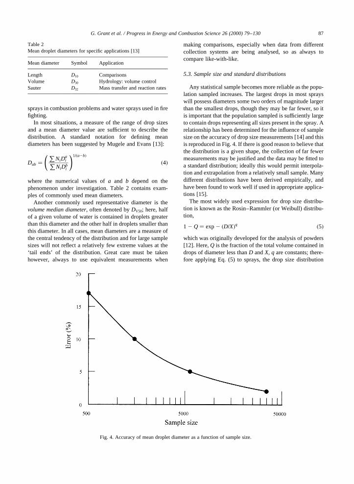
Any statistical sample becomes more reliable as the popu-lation sampled increases. The largest drops in most sprayswill possess diameters some two orders of magnitude largerthan the smallest drops, though they may be far fewer, so itis important that the population sampled is sufficiently largeto contain drops representing all sizes present in the spray. Arelationship has been determined for the influence of samplesize on the accuracy of drop size measurements [14] and thisis reproduced in Fig. 4. If there is good reason to believe thatthe distribution is a given shape, the collection of far fewermeasurements may be justified and the data may be fitted toa standard distribution; ideally this would permit interpola-tion and extrapolation from a relatively small sample. Manydifferent distributions have been derived empirically, andhave been found to work well if used in appropriate applica-tions [15].
The most widely used expression for drop size distribu-tion is known as the Rosin–Rammler (or Weibull) distribu-tion,
1 2 Q� exp2 �D=X�q �5�which was originally developed for the analysis of powders[12]. Here,Q is the fraction of the total volume contained indrops of diameter less thanD andX, q are constants; there-fore applying Eq. (5) to sprays, the drop size distribution
G. Grant et al. / Progress in Energy and Combustion Science 26 (2000) 79–130 87
Fig. 4. Accuracy of mean droplet diameter as a function of sample size.
Table 2Mean droplet diameters for specific applications [13]
Mean diameter Symbol Application
Length D10 ComparisonsVolume D30 Hydrology: volume controlSauter D32 Mass transfer and reaction rates
may be described in terms of the two parametersX andq.The latter gives a measure of the spread of the drop sizes; thehigher the value ofq, the more uniform is the spray. In thelimit where q is infinite, all the drops are of the same size,i.e. the spray ismonodisperse. Further discussions of theapplication of the Rosin–Rammler distribution have beenpublished elsewhere [16–18].
5.4. Practical methods for measuring drop size distribution
Droplet sizing techniques are diverse and the preferredmethod for a given situation depends on the implicit natureof the spray and the intended end use for the data. Measuringthe individual sizes of a large number of small, swiftlymoving bodies is not a trivial task and modern optical tech-niques are used almost exclusively. These have two mainadvantages over other, older methods (e.g. the collection ofdrops on slides or electrical techniques): they are non-intru-sive and they allow measurements over very short and/orvery sharply defined time intervals. Lefebvre [12] hasreviewed mechanical, electrical and optical methods ofspray characterisation and the last of these has also beenthe subject of an extensive review by Chigier [19]. Theapplication of optical measurement techniques in the char-acterisation of typical fire-fighting sprays has beendescribed by several authors [17,20–22].
Measuring the sizes of droplets and producing afrequency distribution is useful only if the sample size islarge enough to ensure reliable results. If enough data arenot available it may still be that the data acquired can befitted to an appropriate model, which will allow interpola-tion over a ‘whole’ distribution. At all stages however, theremust be sufficient information to permit informed compar-isons between sprays. For example, two nozzles may eachproduce a spray that may be described as a ‘500mm spray’.As it is highly unlikely that each droplet in the spray isexactly that size, the designation ‘500mm’ infers someform of ‘mean size’; however, several different methodsof calculating mean sizes are regularly used, depending onthe application (Table 2). In addition, the width of the sizedistribution may be important but is undefined in this exam-ple. Both nozzles may produce droplets with an arithmeticmean size of 500mm but one may produce droplets in therange 495–505mm and the other in the range 0–1000mm;therefore the sprays may not be interchangeable for a givenapplication. Finally, each droplet sizing technique is subjectto error, and the degree of error must be quantified, particu-larly if comparisons are made between results obtainedusing different techniques.
5.5. Determination of spray pattern
While a knowledge of the droplet size distribution isimportant, this information alone is insufficient to char-acterise the fire-fighting efficiency of a water spray. It isequally important to know how the spray spreads out
after leaving the nozzle; this requires the determinationof the ‘spray angle’, ‘spray distance’ and ‘spray density’� _m00w� [10,16].
6. Modes of application of fire-fighting water
6.1. Solid jets
6.1.1. Origins of jet instabilityWater discharged in the form of a jet appears initially as a
solid tube-like flow which undergoes a gradual transition tothe separated flow characteristic of a ‘diffuse jet’. The prin-cipal agents responsible for this transition have been identi-fied as the internal turbulence in the water stream and thesteep velocity gradient generated between the jet and theambient air [10]. The break-up of a solid jet is more abruptwith smaller diameter nozzles operating at higher pressures;air–foam jets which are initially less ‘solid’, are even moreprone to early break-up.
6.1.2. Optimum pressure head at the nozzleThe range and stability of a water jet depend critically
upon the nozzle pressure. In the 1960s, opinion was dividedover the optimum operating pressure required to produce ‘agood extinguishing water jet’ [10]. The notion of ‘soft’ and‘hard’ solid water jets was introduced, where the formeremployed exit pressures which tended to preserve the‘solid’ nature of the jet while the latter were more unstableand were prone to earlier jet break-up close to the nozzleexit [10]. Hard jets were deemed to provide better penetra-tion of deep-seated, glowing fires and improved heat absorp-tion following the shattering of the jet on impact. The solidjet was considered essential for fighting rapidly developingfires and where strong draughts were generated, though theuse of a wide-area spray jet with large (high momentum)water droplets was considered a pragmatic option in somecases.
6.1.3. Height of throw and width of spreadThe calculation of jet trajectory is simplified by assuming
that the fluid stream behaves in a similar manner to a solidprojectile [10]. While this model is attractive, in practice theinteraction between the jet and the atmosphere introducessignificant changes in the dynamics. It can be demonstratedthat the maximum throw of a jet is achieved with an initialangle of,328 while for a solid projectile the critical angle is458. In order to achieve the maximum vertical height ofthrow, an initial discharge angle of 808 has been recom-mended [10].
6.2. Diffuse jets
6.2.1. Early use of sprays in fire-fightingIt has been noted that the ‘solid’ jet is an unstable flow
regime, tending always to break-up and undergo transitionto a diffuse jet. A shift towards the latter as the preferred
G. Grant et al. / Progress in Energy and Combustion Science 26 (2000) 79–13088

delivery mode for fire-fighting water has been driven bythe observation that for certain types of fire, very efficientextinguishment may be achieved using only a smallamount of water. The origins of spray-jet technologyhave been traced back to 1877, while in 1925 and 1933the use of sprays was advocated for ‘damping downgases’ and fighting Class ‘B’ fires, respectively [10].Following the Second World War, it was postulated thathigh-pressure sprays (which were believed to contain veryfine drops) represented the ultimate in fire-fighting effi-ciency [23]. On the contrary, an extensive study involvingthe London and Birmingham Fire Brigades [24] found nomaterial advantage in increasing the operational pressureabove ,7 bar as any theoretical advantage of such finesprays was offset by their limited trajectory.
6.2.2. Definition of spraysThe spectrum of droplet sizes is shown in Fig. 5
[10,12,25]; the size categories in upper area of thefigure (‘colloidal’, ‘dust’ etc.) are reproduced fromHerterich [10], where the ‘average’ size range from100 to 1000mm was deemed to be of most interestfor fire fighting. The text below thex-axis shows therange defined as ‘fine sprays’ [25], together with theapproximate locations of ‘aerosols’, ‘nozzles’ and‘sprinklers’ in the droplet spectrum. The boundarybetween ‘sprays’ and ‘mists’ is somewhat arbitrary,however, although standard definitions are emerging(see Section 6.3).
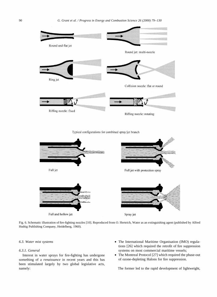
6.2.3. Methods of spray productionFundamentally, the function of a spray nozzle is to accel-
erate and atomise water and to disperse the resulting drops
[11]. Spray nozzles for fire-fighting may be classified bythree distinct types [10].
• Pressure atomisers: the water is moved within the nozzleand the ambient air is still.
• Gaseous atomisers: the water is essentially stationary andthe gas which effects the atomisation moves rapidlywithin the nozzle.
• Rifling nozzles: the nozzle remains stationary, while thewater is given a forward motion and also a rotationalmotion. After ejection at the nozzle, the leading edge ofthe liquid takes the form of a hollow cone, the openingangle of which may be large or small.
The main types of fire-fighting jets and sprays and theiroperating principles are illustrated in Fig. 6.
Several practical requirements for fire-fighting nozzleshave been suggested [10]:
• As fire-fighting water is seldom clean, it is important thatspray nozzle apertures should not be too small in order toprevent blockages;
• ‘Multi-purpose’ fire-fighting branches offer importantadvantages on the fire-ground, permitting the productionof a solid stream, a spray jet of varying angle or a combi-nation of the two;
• The spray nozzle should provide a flowrate of100 l min21 and 400 l min21 respectively, where smallor large jet pipes are used and these flowrates must beattained at pressures of,5 bar;
• At 5 bar, the mean droplet diameter must be 500–1500mm;
• Efficient nozzle design minimises the energy required toachieve atomisation, ensuring satisfactory meandistances of throw at operating pressures of 5 bar.
G. Grant et al. / Progress in Energy and Combustion Science 26 (2000) 79–130 89
Fig. 5. Spectrum of droplet diameters [10,12,25].
6.3. Water mist systems
6.3.1. GeneralInterest in water sprays for fire-fighting has undergone
something of arenaissancein recent years and this hasbeen stimulated largely by two global legislative acts,namely:
• The International Maritime Organisation (IMO) regula-tions [26] which required the retrofit of fire suppressionsystems on most commercial maritime vessels;
• The Montreal Protocol [27] which required the phase-outof ozone-depleting Halons for fire suppression.
The former led to the rapid development of lightweight,
G. Grant et al. / Progress in Energy and Combustion Science 26 (2000) 79–13090
Fig. 6. Schematic illustration of fire-fighting nozzles [10]. Reproduced from O. Herteich, Water as an extinguishing agent (published by AlfredHuthig Publishing Company, Heidelberg, 1960).

low impact, high efficiency (low water demand) mistsystems to replace existing shipboard sprinkler systemswhile the intended phase-out of Halon fire suppressantsprompted an ongoing search for alternative technologieswhich preserve the benefits of a clean ‘total flooding’agent yet are environmentally benign.
6.3.2. Definitions of water mistThe definition of awater mistadopted in the NFPA 750
standard [28] is: ‘a water spray for which theDV99 (99%volume diameter) as measured at the coarsest part of thespray in a plane 1 m from the nozzle, at its minimumoperating design pressure, is less than 1000mm’. Bycomparison, in a conventional sprinkler systemDV99 maybe of the order of 5000mm [29]. It is argued that water mistfire suppression systems (WMFSS) rely on the production ofrelatively small (,500mm) droplet sprays to extinguishfires and that the very low terminal velocities of the smallestdroplets (,100mm) allow the mist to circulate aroundobstructions and to extinguish fires in the manner of atotal flooding gas [29]. It has been suggested that theNFPA definition is too loose, because it permits dropsizes, which are not dissimilar to those produced by conven-tional waterspray and sprinkler systems. An alternative defi-nition has been advanced [30]: ‘a water distribution of finedrops having a mean diameter of 80–200mm and aDV99 lessthan or equal to 500mm’. This definition ensures a verysmall average drop diameter in order to prevent manufac-turers from offering slightly modified standard waterspraysystems as ‘mist’ systems.
Mawhinney and Solomon [31] proposed a mist classifica-tion system based on a ‘cumulative percent volume’ distri-bution plot which distinguishes between ‘coarser’ and‘finer’ water sprays (Fig. 7). Thus, for ‘Class 1’ sprays,90% of the volume is contained in droplets less than200mm in diameter; Class 2 and Class 3 sprays are definedin a similar manner. It is argued that sprays comprising
almost entirely of ‘fine’ drop sizes will evaporate rapidlyin the fire environment and facilitate the characteristic extin-guishment mechanisms of water mist, i.e. flame cooling andvolumetric displacement of oxygen through the productionof water vapour [31]. In practice, Class 1 and Class 2 spraysare suited to the suppression of liquid pool or spray fires orwhere ‘splashing’ of the fuel is to be avoided. Class 3 spraysare a better choice where fuel wetting is tolerable, or evennecessary to achieve extinguishment, for example whentackling Class ‘A’ fires.
6.3.3. Design of water mist nozzlesThe physical nature of water presents a fundamental
problem in nozzle design: water possesses a high surfacetension which makes it relatively difficult to atomise effec-tively [32] because the consolidating influence of this forcemust be disrupted through the action of other internal and/orexternal forces [12]. In the absence of such disruptiveforces, an isolated liquid droplet in equilibrium assumes aspherical shape to satisfy the minimum surface energycondition. Any change in system geometry promoted byexternal distorting forces, such as aerodynamic forces, isresisted by a combination of stabilising internal viscousforces and surface tension. Atomisation occurs only whenthe magnitude of the external forces exceeds the surfacetension force.
Nozzles originally designed for agricultural or industrialapplications have been adopted or modified for use in firesuppression applications and the various designs may besubdivided broadly into ‘single-fluid’ and ‘twin-fluid’types [32]:
6.3.3.1. Single-fluid mist nozzles
• Hollow cone–single fluid:a swirling motion is induced inthe liquid within the nozzle producing a plume wheremost of the droplets are concentrated at the outer edge.
G. Grant et al. / Progress in Energy and Combustion Science 26 (2000) 79–130 91
Fig. 7. Classification of water sprays by dropsize distribution [31]. Reprinted with permission from Fire Protection Handbook, 18th ed.,Copyrightq 1997, National Fire Protection Association, Quincy, MA 02269.

• Solid cone–single fluid:an approximately homogeneousconcentration of droplets is distributed over a round,square or rectangular ‘footprint’.
• Flat spray–single fluid:an elliptical orifice produces asheet spray with a relatively uniform distribution ofdroplets, which is particularly suitable for protectingequipment in narrow voids.
Single-fluid systems are also known as ‘simplex’ or‘hydraulic’ types. For these, the resulting spray is influencedby the water pressure according to the following approxi-mate relationship:
D301
D302
/ p2
p1
� �0:3
�6�
whereD30 is the ‘volume mean diameter’ (Table 2) andp isthe nozzle operating pressure. The improvement of atomisa-tion efficiency at higher pressures is the reason why somesystems operate at around 100–300 bar.
6.3.3.2. Twin-fluid mist nozzlesThe alternative to single-fluid mist production is the dual fluid head, also known as‘air atomising’, ‘duplex’ or ‘pneumatic’ nozzles. In thesesystems a gas, commonly nitrogen, is mixed with water ina highly turbulent environment, producing a fine mist whichis then expelled through single or multiple outlets. Effectiveatomisation occurs at low operating pressures (,5–6 bar),with average droplet diameter decreasing with increasinggas:liquid pressure ratio. These systems may also providehigh initial droplet velocities and good horizontal projectioncharacteristics. Disadvantages are a high gas demand andthe need for a twin supply manifold, resulting in anincreased cost over single-fluid systems.
Single-fluid nozzles can produce droplets as small as90–100mm at pressures around 5–6 bar, but to achievesmaller droplets (down to,30mm), twin-fluid systemsare required [25]. In addition, despite the theoretical andexperimental evidence that such small droplets are ex-tremely effective in combustion suppression, the productionof sprays containing the bulk of their water in droplets smal-ler than,30mm remains problematic.
6.4. Methods of water application used by the fire service
6.4.1. Jet/spray branches for fire-fightingDuring the early 1980s, the UK Home Office conducted a
practical appraisal of a wide range of commercially avail-able jet/spray branches for use with a standard 70 mmdiameter hose [33–36]. The broad aim of the study was:‘… to evaluate the range of hand-controlled branches avail-able in order to give guidance on their cost effectiveness andefficiency.’ Initially, 31 different branches were assessed interms of hydraulic criteria (jet throw and quality, spraypatterns and flow vs. pressure characteristics), ease of hand-ling, ‘robustness’ and general maintenance requirements[33-35]. The interested reader is directed to these references,however, there follows a brief discussion of some of themore interesting results.
In general it was found that jet throw was roughly propor-tional to flowrate, although there was considerable scatter;hence the ‘maximum’ and ‘minimum’ values shown inTable 3 are approximate extremes taken from the graphicaldata [33].
The hydraulic performance data for branches operatedpurely as sprays were also presented [33]; however herethe situation was more complex, owing to additionalvariables such as cone included angle and spray breadth.Some examples of the spray branch performance data areshown in Table 4 [33].
6.4.2. High and low pressure hosereel systemsThe jet/spray branches described above are deployed only
when it is necessary to deliver a large quantity of water atthe fireground. The vast majority of fires, particularly thosewithin residential buildings, are attacked initially andfrequently extinguished completely using the lower capacityhosereel systems which are also carried on fire appliances[20]. As far back as 1960 it was observed that the use ofhosereels had steadily increased to the point where 75% ofthe fires in which water was applied by the UK Fire Servicewere extinguished in this manner [37]. Hosereel systemsemploy flexible rubber hoses of,19 mm diameter and arefaster to deploy and more flexible in operation than mainjets; however the maximum flowrate is much lower, at,150 l min21.
Up until the mid 1960s, the maximum pressure availablefor hosereel systems on fire appliances was around 10 bar[20]. This situation changed with the development of ‘highpressure’ pumps, which delivered pressures of up to,30–40 bar at the hosereel outlet on fire appliances. The intro-duction of these pumps encouraged the development of newhosereel guns with a range of droplet sizes, velocities, flow-rates and spray patterns; contemporary units operating at upto 10 bar have been defined as ‘low pressure’ and thoseoperating at greater pressures have been designated ‘highpressure’ [20]. Advocates of high pressure hosereel systemscite the ability to produce a finer spray as a critical advan-tage during fire-fighting; the technical reasons underlying
G. Grant et al. / Progress in Energy and Combustion Science 26 (2000) 79–13092
Table 3Hydraulic performance data for branches operating as jets [33]
Operatingpressure(bar)
Elevation(8)
‘Minimum’throw/flowm/(l min21)
‘Maximum’throw/flowm/(l min21)
7 0 12/120 17/10307 20 23/120 42/10307 35 25/120 48/10503 0 8/100 11/7003 20 17/100 32/7003 35 18/100 40/700

G.
Gra
nt
et
al.
/P
rog
ress
inE
ne
rgy
an
dC
om
bu
stionS
cien
ce2
6(2
00
0)
79
–1
30
93
Table 4Hydraulic performance data for branches operating as sprays at 08 elevation [33]
Operating pressure (bar) Flow (l min21) Spray cone included angle (8) Throw (m) Breadth (m) Range to breadth (m) Comments [33]
7 224 20 14 0.9 6.0 Entrained fog visible to 20m, measured ‘throws’ referto large droplets.
7 278 158 2.2 16.5 2.0 Coarse, hollow spray, novisible entrainment.
3 296 28 9.8 2.4 6.0 Coarse spray, hollow cone.3 311 180 1.8 14.3 1.0 Hollow cone, ‘spoke effect’.
this belief have been outlined in the earlier discussion on thedefinition of water mist. There is a price to be paid for theseadvantages however, because higher quality hoses andfittings are essential and more rigorous maintenance isrequired [37].
7. Desirable droplet characteristics for fire-fighting
7.1. Spray cooling of gaseous combustion products
The great advantage of sprays in heat transfer applica-tions, viz. their large surface area to volume ratio hasalready been mentioned. The evaporation of drops withina spray involves simultaneous heat and mass transferprocesses where the heat required is transferred to thedrop surface by conduction and convection from thesurrounding hot gas and water vapour is transferred byconvection and diffusion back into the gas stream [12].Herterich [10] noted that the rate of vapourisation of adroplet is dependent upon its surface area, the characteristicheat transfer coefficient (a ) and the relative velocitybetween the droplet and the surrounding gas.
For a spherical droplet in a quiescent atmosphere, the heattransfer coefficient may be written,
a � constant× kd�W m22 K21� �7�
wherek is the thermal conductivity of the surrounding gas(W m21 K21) andd is the droplet diameter (m).
However, in practical fire-fighting operations it cannot beassumed that the relative velocity between spray dropletsand the surrounding air is zero and more complex mathe-matical expressions are required to describe the heat transferprocess. The measurement of droplet evaporation in movingairstreams has been studied using diverse and ingenioustechniques [38,39]. The resulting data are conventionallycorrelated using well-known non-dimensional heat transferand fluid flow parameters:
Nu� adk�Nusselt number� �8�
Sc� n
D�Schmidt number� �9�
Pr � chk�Prandtl number� �10�
Re� udn�Reynolds number� �11�
Pe� Re·Pr� udK�P�eclet number� �12�
wherea; d; k have been defined previously andn;h; c are thekinematic viscosity, dynamic viscosity and specific heatcapacity of air at constant pressure, respectively. In addition,the symbolsD andK represent the mass diffusivity of water
vapour in air (m2 s21) and the thermal diffusivity of air(m2 s21), respectively; the latter is defined by the expres-sion,
K � krc
�13�
again using the above symbol definitions.Ranz and Marshall [38] performed experiments on
droplet evaporation in air at temperatures up to 2208C, fordrop diameters in the range 600–1000mm and at 0# Re#200: The expression,
Nu� 2 1 0:6Pr1=3Re1=2 �14�was found to correlate the experimental data well and alsosatisfied the theoretical requirement thatNu� 2 at Re� 0(zero relative velocity case); the range of validity was givenas 1, Re, 70× 103 and 0:6 , Pr , 400:
Kincaid and Longley [39] employed Eq. (14) in theirtheoretical model of spray evaporation in the context ofagricultural sprinkler irrigation. Droplet temperatures werecalculated as a function of time for a range of droplet sizes,velocities and initial temperatures at ejection. The dropletdiameter was found to have a significant effect on the rate oftemperature change whereas the effect of droplet velocitywas negligible. Regarding the rate of droplet evaporation, itwas found that higher gas temperatures and lower relativehumidity resulted in the greatest evaporation rates. Initialdroplet velocities were in the range 0–10 m s21 withdiameters between 300 and 2000mm. However, the rangeof ambient temperatures relevant to agricultural problemswas,0–408C, much lower than in fire-fighting operations.
Using their model, Kincaid and Longley [39] determinedthat if the initial droplet temperature was not equal to theambient wet-bulb temperature, then it could take some 8 sbefore this temperature was reached. Once at this tempera-ture; however, all subsequent heat received by the dropletwas dissipated as latent heat lost in the evaporation process;that is, the latent heat lost was exactly balanced by thesensible heat input to the droplet from the air. In contrastto agricultural applications where droplet evaporationequates to agrochemical wastage and is undesirable, ef-ficient droplet evaporation is beneficial in fire-fightingsprays. Kincaid and Longley [39] also showed that reducingthe droplet diameter reduces the time taken to reach the wet-bulb temperature and that ford less than,550mm, the timedelay is negligible.
Rasbash [40] discussed the limitations of Eq. (14) asapplied to the evaporation of drops immersed in gaseousatmospheres at elevated temperatures (i.e. above the2208C maximum employed previously [38]). It was foundthat, for droplets evaporating within Bunsen burner flames,the measured evaporation times were consistently some60% greater than those predicted by Eq. (14). The discre-pancy was attributed to the insulating effect of the watervapour as it passed through the boundary layer surroundingthe drop, tending to reduce the rate at which heat was
G. Grant et al. / Progress in Energy and Combustion Science 26 (2000) 79–13094
transferred to the liquid surface. Although the thermalconductivity of air and water vapour is similar at 1008C(,0.028 W m21 K21), the specific heat capacity of watervapour is twice as high (Cp , 2000 J kg21 K21) whichwould be consistent with the observed insulating effect.Rasbash [40] proposed the expression,
Nu� l 0
l 0 1 0:4b�2 1 0:6Pr1=3Re1=2� �15�
to take account of this effect, wherel 0 is the total heat ofvapourisation of the drops andb is the increase in enthalpyof the water vapour when raised from the surface tempera-ture of the drop to the temperature of the flame.
Herterich [10] reported an alternative ‘corrected’ form ofEq. (14),
Nu� adk� 2:831 0:6Pr1=3Re1=2 �16�
which was derived in order to explain the observed rates ofheat transfer to droplets inexcessof those predicted by Eq.(14) and where values ofk, ReandPr are calculated usingthe average physical properties of the air and the steam layeraround the droplet. It should be noted however that the‘correction’ in Eq. (16) is in the opposite direction to thatproposed by Rasbash [40], where reduced rather thanenhanced experimental heat transfer rates were reported.The reason for this discrepancy is unclear, although ithas been suggested recently that the presence of certainsurfactants may reduce the evaporation rates of water
droplets; this effect is discussed at the end of the presentsection.
Eq. (16) was employed by Gu¨ttler [41] to estimate thetotal quantity of heat transmitted to high- and low-pressuremonodisperse water sprays using the expression,
W � aO �W m23 K21� �17�where a is the heat transfer number for an individualdroplet, as discussed above anO is the total surface areaof the spray per unit volume of water (m2 m23 or m21).Guttler’s [41] calculations were somewhat simplistic andused the expression [10],
d < 450=u2 �18�to estimate a representative drop size from the notionaldischarge velocities of fire-fighting sprays. Eq. (18) yieldspredictions of droplet diameters which are inversely propor-tional to the square of the initial spray velocity; hence higherpressure sprays are predicted to produce ever smaller dropletsizes. In practice however, the relationship between nozzlepressure and droplet diameter does not remain monotonicindefinitely and above a certain pressure the mean drop sizeis found to increase again due to droplet coalescence.Despite the rather approximate nature of Gu¨ttler’s [41]subsequent methodology, Eq. (17) is a useful rule-of-thumb for estimating the cooling capacity of water sprays.The application of this expression to practical polydispersespays, however, requires a detailed knowledge of the drop
G. Grant et al. / Progress in Energy and Combustion Science 26 (2000) 79–130 95
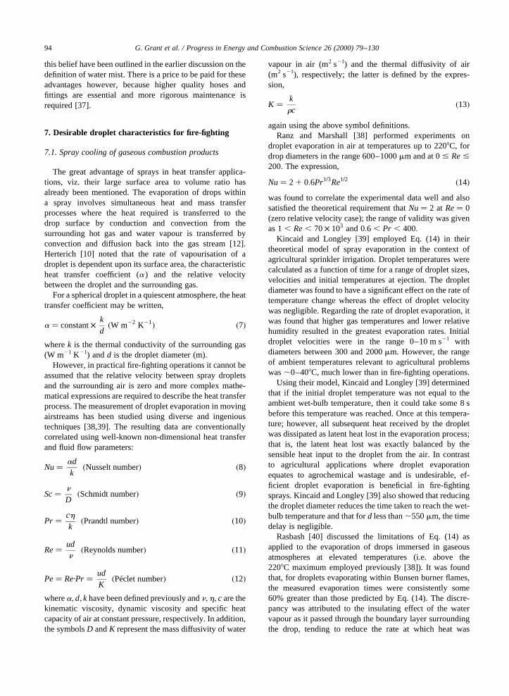
Fig. 8. Heat transfer by convection to drops of water from a flame at 10008C [40]. Reproduced from Proceedings of the Symposium on theInteraction of Fluids and Particles. Reproduced by permission of the Building Research Establishment.
size distribution in order to calculateO, the spray area perunit volume. The practical situation is complicated furtherbecause the droplet diameter and velocity will both reducewith time and temporal variations have been absent from theforegoing discussion.
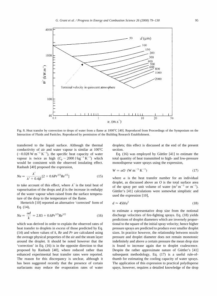
Rasbash [40] employed Eq. (15) to model the heattransfer between flames of freely burning hydrocarbonfires and water sprays. The rate of convective heat transferwas plotted as a function of drop velocity for drop sizesranging from 50 to 2000mm, assuming a flame temperatureof 10008C (Fig. 8); in general, higher droplet velocities andsmaller droplet diameters were found to increase the heattransfer rate. The model also included temporal variations indroplet velocity and diameter, which enabled estimates to bemade of the droplet penetration distance into the flame priorto evaporation (Fig. 9). The heat transfer from a unit volumeof flame was defined as the product of the total surface areaof the drops present, the heat transfer coefficient and thetemperature difference between the drop surface and theflame. Given a mass flux_m00d (kg m22 s21) of spray enteringthe flame, comprising drops of diameterd (m) travelling atud (m s21) then the total mass of drops per unit volume isgiven by _m00d=ud: From Eqs. (1) and (3), the total surface area
of the spray is,
O� 6 _m00drwdud
�m2 m23� �19�
whererw is the density of water; see also Eq. (17). Rasbash[40] used this expression to define a ‘heat transfer capacity’for the spray,
X � 6 _m00drwdud
aDT �W m23� �20�
wherea is the heat transfer coefficient for a drop andDT isthe temperature differential described above; thusX isequivalent toW·DT in Guttler’s terminology [41].
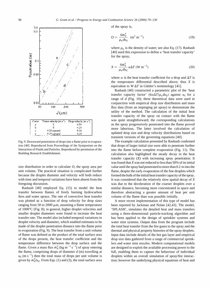
Rasbash [40] constructed a parametric plot of the ‘heattransfer capacity factor’�6aDT=rwdud� against ud for arange ofd (Fig. 10); these theoretical data were used inconjunction with empirical drop size distribution and massflux data (from an impinging jet spray) to demonstrate theutility of the method. The calculation of the initial heattransfer capacity of the spray on contact with the flamewas quite straightforward; the corresponding calculationsas the spray progressively penetrated into the flame provedmore laborious. The latter involved the calculation ofupdated drop size and drop velocity distributions based ontransient versions of the governing equations [40].
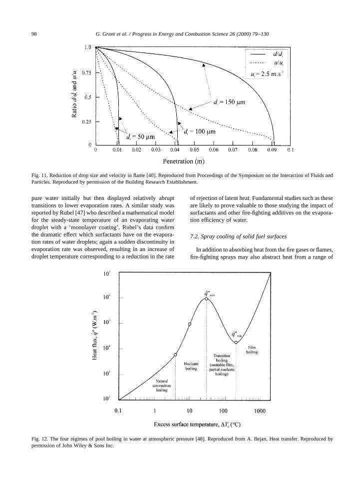
The example calculation presented by Rasbash confirmedthat drops of larger initial size were able to penetrate furtherinto the flame before complete evaporation (Fig. 11). Thecalculation also highlighted the steady decay in the heattransfer capacity (X) with increasing spray penetration. Itwas found thatXwas not reduced to less than 50% of its initialvalue until the spray had penetrated to more than 0.2 m into theflame, despite the early evaporation of the fine droplets whichformed the bulk of the initial heat transfercapacity of the spray.It was considered that the relatively slow spatial decay ofXwas due to the deceleration of the coarser droplets over asimilar distance, becoming more concentrated in space andtherefore abstracting a greater amount of heat per unitvolume of the flame than was possible initially.
A more recent implementation of this type of model hasbeen reported by Jackman and Nolan [42,43]. The model,‘SPLASH’, simulates the detailed heat and mass transfersusing a three-dimensional particle-tracking algorithm andhas been applied to the design of sprinkler systems andwater mist systems. Output data from the program includethe total heat transfer from the fire gases to the spray and thethermal and physical property histories of the spray droplets.Input data include details of the hot gas layer and empiricaldrop size data gathered from a range of commercial sprink-lers and water mist nozzles. Modern computational modelsare designed to exploit the available processing power to thefull, enabling them to capture the behaviour of individualdroplets within an overall simulation of spray/fire interac-tion; however the underlying physical equations of heat and
G. Grant et al. / Progress in Energy and Combustion Science 26 (2000) 79–13096
Fig. 9. Downward penetration of drops into a flame prior to evapora-tion [40]. Reproduced from Proceedings of the Symposium on theInteraction of Fluids and Particles. Reproduced by permission of theBuilding Research Establishment.
mass transfer are generally the same as those employed inearlier models.
Detailed accounts of the mechanics of droplet evapora-tion are found in the literature dedicated to aerosol scienceand transfer processes. Kucherov [44] presented a mathe-matical description of droplet evaporation occurring in eachof the five ‘evaporation re´gimes’: diffusion, diffusional–convective, subsonic, sonic and explosive (in order ofincreasing rate of heat transfer). Kucherov [44] alsopresented example calculations of drop temperature andradius for all five evaporation re´gimes; however the theorypresented was valid only for very small droplets (d , 1–10mm), much smaller than normally encountered in fire-fighting applications. Ferron and Soderholm [45] estimatedthe evaporation rates of pure water droplets and the stabil-isation times of particles containing salt in order to model
aerosols produced by medical nebulisers. The lifetimes ofpure water droplets in air at 208C and varying relativehumidity were described; however droplet sizes wereagain of the order of,10mm.
Sadd et al. [46] described an experimental investigationof water droplet evaporation where the droplets were dopedwith various soluble surfactants; the ultimate objective wasto model the evaporation of aerosols contaminated withsoluble, involatile surfactants. The evaporation of dropletsof initial size ,1200mm was observed with a micrometermicroscope to an accuracy of,4 mm; the temperatureranged between 13 and 298C and the relative humiditywas varied between 3 and 92%. The data confirmed thatsurfactants are capable of generating a very high resistanceto mass transfer but have no effect on heat transfer; thekinetics of evaporation were observed to follow those of
G. Grant et al. / Progress in Energy and Combustion Science 26 (2000) 79–130 97
Fig. 10. Heat transfer capacity factor for various drop sizes and velocities [40]. Reproduced from Proceedings of the Symposium on theInteraction of Fluids and Particles. Reproduced by permission of the Building Research Establishment.
pure water initially but then displayed relatively abrupttransitions to lower evaporation rates. A similar study wasreported by Rubel [47] who described a mathematical modelfor the steady-state temperature of an evaporating waterdroplet with a ‘monolayer coating’. Rubel’s data confirmthe dramatic effect which surfactants have on the evapora-tion rates of water droplets; again a sudden discontinuity inevaporation rate was observed, resulting in an increase ofdroplet temperature corresponding to a reduction in the rate
of rejection of latent heat. Fundamental studies such as theseare likely to prove valuable to those studying the impact ofsurfactants and other fire-fighting additives on the evapora-tion efficiency of water.
7.2. Spray cooling of solid fuel surfaces
In addition to absorbing heat from the fire gases or flames,fire-fighting sprays may also abstract heat from a range of
G. Grant et al. / Progress in Energy and Combustion Science 26 (2000) 79–13098
Fig. 12. The four re´gimes of pool boiling in water at atmospheric pressure [48]. Reproduced from A. Bejan, Heat transfer. Reproduced bypermission of John Wiley & Sons Inc.
Fig. 11. Reduction of drop size and velocity in flame [40]. Reproduced from Proceedings of the Symposium on the Interaction of Fluids andParticles. Reproduced by permission of the Building Research Establishment.

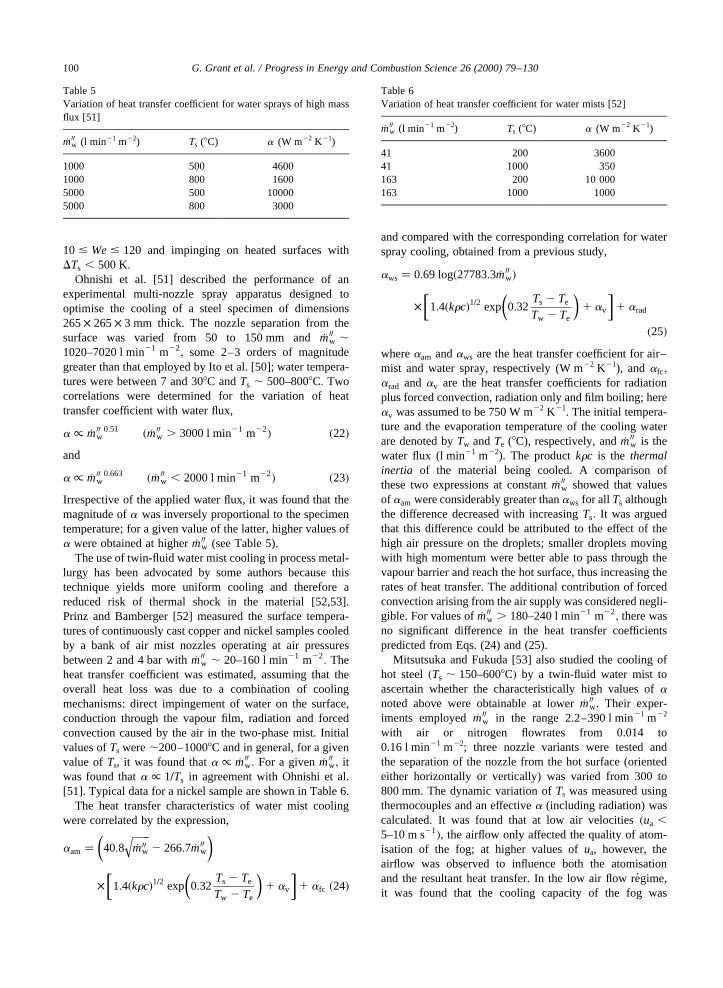
hot solid surfaces, including the burning (Class ‘A’) fuel,unburned fuel and various non-combustible surfaces such asbrick or metal structural elements. Bejan [48] identified fourdistinct regimes of boiling heat transfer for water at atmo-spheric pressure, depending on the temperature of the solidsurface (Ts). In order of increasing excess surface tempera-ture �DTs�; these are:natural convection boiling, nucleateboiling, transition boilingandfilm boiling (Fig. 12). Here,DTs is defined as the surface temperature minus thesatura-tion temperatureof liquid (Tsat), the latter being the tempera-ture of the liquid–vapour interface at the local pressure.
Given the high surface temperatures associated with thecombustion of Class ‘A’ fuels, it is apparent that the initialapplication of water will produce ‘film boiling’ on the fuelsurface; this re´gime occurs aboveDTs ,200–3008C and isso-called because a continuous film of water vapour isformed between the solid surface and the liquid waterdroplets [48]. The decrease inTs is accompanied by agradual reduction in heat flux� _q00� until the Leidenfrosttemperatureis reached, corresponding to a minimum heatflux leaving the surface� _q00min�; at this point the vapour filmcollapses, causing a sudden increase in_q00 and a sharp rise ina [49]. For water at 1 atm, Bejan [48] estimated the Leiden-frost point to occur atDTs , 100–2008C and a re´gime ofpartial film boiling (or transition boiling) to exist in therange, 308C , Ts , 2008C:
Boiling heat transfer has been studied extensively in themetallurgical processing industry where spray cooling isused extensively in the continuous casting of metals[49–54]. Reiners et al. [49] reported a method for esti-mating the heat transfer coefficient pertaining to waterspray cooling of steel castings whereTs was typically inthe range 800–14008C, corresponding to the stable film boil-ing regime. It was found that the heat transfer coefficientremained constant (a , 140 W m22 K21) over the surfacetemperature range investigated (Ts , 830–9508C), although
locally high values (a , 2800 W m22 K21) were recordedwhen water–air nozzles were operated at high throughputs.
Ito et al. [50] reported an analytical study of spray coolingand the associated film boiling heat transfer; these workersdefined ‘spray cooling’ as that originating from a single fluidnozzle, while mist (or fog) cooling was obtained viatwin-fluid nozzles employing a lower mass flux ofwater � _m00w�: The behaviour of spray droplets impingingonto horizontal heated surfaces was characterised in termsof the non-dimensionalWeber number,
We� u�rd=s�1=2 �21�which is the ratio of the inertial force to the surface tensionforce. ForWe# 30; droplets rebounded immediately fromthe heated surface without disintegrating, while for therange 30# We# 80 they tended to spread radially overthe surface, forming a thin vapour layer on the underside,before contacting with the hot surface and finally rebound-ing. However, for values ofWe$ 80; impinging dropletsformed a thin spreading liquid film upon collision, whichsubsequently disintegrated into smaller droplets. Rymkie-wicz and Zapalowicz [55] (Fig. 13), assuming three mainsystem variables presented a qualitative illustration of thesedroplet-surface interactions: droplet size, impact velocityand initial surface temperature.
The model developed by Ito et al. [50] included heattransfer by radiation, convection and evaporation; the tran-sient reduction in droplet diameter was also modelled. Themodel was compared with empirical data obtained fromexperiments with water spray nozzles operating in therange _m00w , 1.8–10.2 l min21 m22 and with volume meandrop diameters in the range,130–550mm; these experi-ments yielded total heat transfer rates in the film boilingregime of _q00 , 25–150 kW m22 at surface excess tempera-tures of,150–5008C. The analytical model was found to bein good agreement with these data for drops of this size, with
G. Grant et al. / Progress in Energy and Combustion Science 26 (2000) 79–130 99
Fig. 13. Droplet–surface interaction matrix [55].
10 # We# 120 and impinging on heated surfaces withDTs , 500 K:
Ohnishi et al. [51] described the performance of anexperimental multi-nozzle spray apparatus designed tooptimise the cooling of a steel specimen of dimensions265× 265× 3 mm thick. The nozzle separation from thesurface was varied from 50 to 150 mm and_m00w ,1020–7020 l min21 m22
; some 2–3 orders of magnitudegreater than that employed by Ito et al. [50]; water tempera-tures were between 7 and 308C andTs , 500–8008C: Twocorrelations were determined for the variation of heattransfer coefficient with water flux,
a / _m00w0:51 � _m00w . 3000 l min21 m22� �22�
and
a / _m00w0:663 � _m00w , 2000 l min21 m22� �23�
Irrespective of the applied water flux, it was found that themagnitude ofa was inversely proportional to the specimentemperature; for a given value of the latter, higher values ofa were obtained at higher_m00w (see Table 5).
The use of twin-fluid water mist cooling in process metal-lurgy has been advocated by some authors because thistechnique yields more uniform cooling and therefore areduced risk of thermal shock in the material [52,53].Prinz and Bamberger [52] measured the surface tempera-tures of continuously cast copper and nickel samples cooledby a bank of air mist nozzles operating at air pressuresbetween 2 and 4 bar with_m00w , 20–160 l min21 m22
: Theheat transfer coefficient was estimated, assuming that theoverall heat loss was due to a combination of coolingmechanisms: direct impingement of water on the surface,conduction through the vapour film, radiation and forcedconvection caused by the air in the two-phase mist. Initialvalues ofTs were,200–10008C and in general, for a givenvalue ofTs, it was found thata / _m00w: For a given _m00w; itwas found thata / 1=Ts in agreement with Ohnishi et al.[51]. Typical data for a nickel sample are shown in Table 6.
The heat transfer characteristics of water mist coolingwere correlated by the expression,
aam� 40:8�����_m00w
q2 266:7 _m00w
� �
� 1:4�krc�1=2 exp 0:32Ts 2 Te
Tw 2 Te
� �1 av
� �1 afc �24�
and compared with the corresponding correlation for waterspray cooling, obtained from a previous study,
aws � 0:69 log�27783:3 _m00w�
� 1:4�krc�1=2 exp 0:32Ts 2 Te
Tw 2 Te
� �1 av
� �1 arad
�25�whereaam andaws are the heat transfer coefficient for air–mist and water spray, respectively (W m22 K21), andafc;
arad andav are the heat transfer coefficients for radiationplus forced convection, radiation only and film boiling; hereav was assumed to be 750 W m22 K21. The initial tempera-ture and the evaporation temperature of the cooling waterare denoted byTw andTe (8C), respectively, and_m00w is thewater flux (l min21 m22). The productkrc is the thermalinertia of the material being cooled. A comparison ofthese two expressions at constant_m00w showed that valuesof aam were considerably greater thanaws for all Ts althoughthe difference decreased with increasingTs: It was arguedthat this difference could be attributed to the effect of thehigh air pressure on the droplets; smaller droplets movingwith high momentum were better able to pass through thevapour barrier and reach the hot surface, thus increasing therates of heat transfer. The additional contribution of forcedconvection arising from the air supply was considered negli-gible. For values of_m00w . 180–240 l min21 m22
; there wasno significant difference in the heat transfer coefficientspredicted from Eqs. (24) and (25).
Mitsutsuka and Fukuda [53] also studied the cooling ofhot steel�Ts , 150–6008C� by a twin-fluid water mist toascertain whether the characteristically high values ofanoted above were obtainable at lower_m00w: Their exper-iments employed _m00w in the range 2.2–390 l min21 m22
with air or nitrogen flowrates from 0.014 to0.16 l min21 m22; three nozzle variants were tested andthe separation of the nozzle from the hot surface (orientedeither horizontally or vertically) was varied from 300 to800 mm. The dynamic variation ofTs was measured usingthermocouples and an effectivea (including radiation) wascalculated. It was found that at low air velocities�ua ,5–10 m s21�; the airflow only affected the quality of atom-isation of the fog; at higher values ofua, however, theairflow was observed to influence both the atomisationand the resultant heat transfer. In the low air flow re´gime,it was found that the cooling capacity of the fog was
G. Grant et al. / Progress in Energy and Combustion Science 26 (2000) 79–130100
Table 6Variation of heat transfer coefficient for water mists [52]
_m00w (l min21 m22) Ts (8C) a (W m22 K21)
41 200 360041 1000 350163 200 10 000163 1000 1000
Table 5Variation of heat transfer coefficient for water sprays of high massflux [51]
_m00w (l min21 m22) Ts (8C) a (W m22 K21)
1000 500 46001000 800 16005000 500 100005000 800 3000
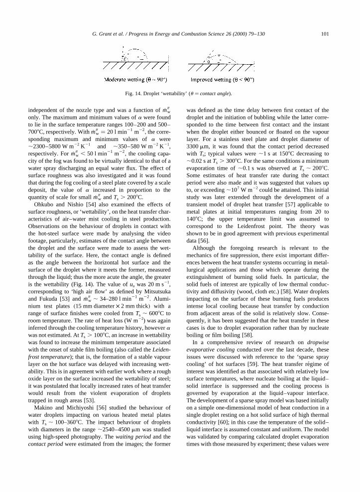
independent of the nozzle type and was a function of_m00wonly. The maximum and minimum values ofa were foundto lie in the surface temperature ranges 100–200 and 500–7008C, respectively. With_m00w � 20 l min21 m22
; the corre-sponding maximum and minimum values ofa were,2300–5800 W m22 K21 and ,350–580 W m22 K21,respectively. For_m00w , 50 l min21 m22
; the cooling capa-city of the fog was found to be virtually identical to that of awater spray discharging an equal water flux. The effect ofsurface roughness was also investigated and it was foundthat during the fog cooling of a steel plate covered by a scaledeposit, the value ofa increased in proportion to thequantity of scale for small_m00w andTs . 2008C:
Ohkubo and Nishio [54] also examined the effects ofsurface roughness, or ‘wettability’, on the heat transfer char-acteristics of air–water mist cooling in steel production.Observations on the behaviour of droplets in contact withthe hot-steel surface were made by analysing the videofootage, particularly, estimates of the contact angle betweenthe droplet and the surface were made to assess the wet-tability of the surface. Here, the contact angle is definedas the angle between the horizontal hot surface and thesurface of the droplet where it meets the former, measuredthrough the liquid; thus the more acute the angle, the greateris the wettability (Fig. 14). The value ofua was 20 m s21,corresponding to ‘high air flow’ as defined by Mitsutsukaand Fukuda [53] and_m00w , 34–280 l min21 m22
: Alumi-nium test plates�15 mm diameter× 2 mm thick� with arange of surface finishes were cooled fromTs , 6008C toroom temperature. The rate of heat loss (W m22) was againinferred through the cooling temperature history, howeverawas not estimated. AtTs . 1008C; an increase in wettabilitywas found to increase the minimum temperature associatedwith the onset of stable film boiling (also called theLeiden-frost temperature); that is, the formation of a stable vapourlayer on the hot surface was delayed with increasing wett-ability. This is in agreement with earlier work where a roughoxide layer on the surface increased the wettability of steel;it was postulated that locally increased rates of heat transferwould result from the violent evaporation of dropletstrapped in rough areas [53].
Makino and Michiyoshi [56] studied the behaviour ofwater droplets impacting on various heated metal plateswith Ts , 100–3608C: The impact behaviour of dropletswith diameters in the range,2540–4500mm was studiedusing high-speed photography. Thewaiting periodand thecontact periodwere estimated from the images; the former
was defined as the time delay between first contact of thedroplet and the initiation of bubbling while the latter corre-sponded to the time between first contact and the instantwhen the droplet either bounced or floated on the vapourlayer. For a stainless steel plate and droplet diameter of3300mm, it was found that the contact period decreasedwith Ts; typical values were,1 s at 1508C decreasing to,0.02 s atTs . 3008C: For the same conditions a minimumevaporation time of,0.1 s was observed atTs , 2008C:Some estimates of heat transfer rate during the contactperiod were also made and it was suggested that values upto, or exceeding,107 W m22 could be attained. This initialstudy was later extended through the development of atransient model of droplet heat transfer [57] applicable tometal plates at initial temperatures ranging from 20 to1408C; the upper temperature limit was assumed tocorrespond to the Leidenfrost point. The theory wasshown to be in good agreement with previous experimentaldata [56].
Although the foregoing research is relevant to themechanics of fire suppression, there exist important differ-ences between the heat transfer systems occurring in metal-lurgical applications and those which operate during theextinguishment of burning solid fuels. In particular, thesolid fuels of interest are typically of low thermal conduc-tivity and diffusivity (wood, cloth etc.) [58]. Water dropletsimpacting on the surface of these burning fuels producesintense local cooling because heat transfer by conductionfrom adjacent areas of the solid is relatively slow. Conse-quently, it has been suggested that the heat transfer in thesecases is due to droplet evaporation rather than by nucleateboiling or film boiling [58].
In a comprehensive review of research ondropwiseevaporative coolingconducted over the last decade, theseissues were discussed with reference to the ‘sparse spraycooling’ of hot surfaces [59]. The heat transfer re´gime ofinterest was identified as that associated with relatively lowsurface temperatures, where nucleate boiling at the liquid–solid interface is suppressed and the cooling process isgoverned by evaporation at the liquid–vapour interface.The development of a sparse spray model was based initiallyon a simple one-dimensional model of heat conduction in asingle droplet resting on a hot solid surface of high thermalconductivity [60]; in this case the temperature of the solid–liquid interface is assumed constant and uniform. The modelwas validated by comparing calculated droplet evaporationtimes with those measured by experiment; these values were
G. Grant et al. / Progress in Energy and Combustion Science 26 (2000) 79–130 101
Fig. 14. Droplet ‘wettability’ (u � contact angle).
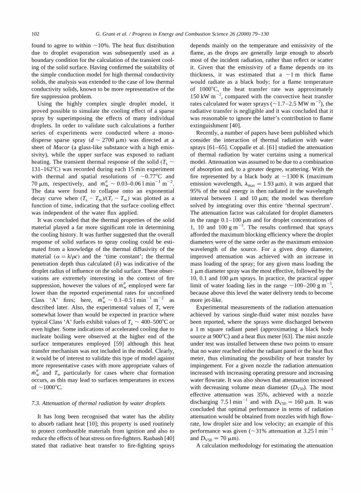
found to agree to within,10%. The heat flux distributiondue to droplet evaporation was subsequently used as aboundary condition for the calculation of the transient cool-ing of the solid surface. Having confirmed the suitability ofthe simple conduction model for high thermal conductivitysolids, the analysis was extended to the case of low thermalconductivity solids, known to be more representative of thefire suppression problem.
Using the highly complex single droplet model, itproved possible to simulate the cooling effect of a sparsespray by superimposing the effects of many individualdroplets. In order to validate such calculations a furtherseries of experiments were conducted where a mono-disperse sparse spray�d , 2700mm� was directed at asheet ofMacor (a glass-like substance with a high emis-sivity), while the upper surface was exposed to radiantheating. The transient thermal response of the solid�Ts ,131–1628C� was recorded during each 15 min experimentwith thermal and spatial resolutions of,0.778C and70mm, respectively, and _m00w , 0:03–0:06 l min21 m22
:
The data were found to collapse onto an exponentialdecay curve when�Ts 2 T∞�=�Ti 2 T∞� was plotted as afunction of time, indicating that the surface cooling effectwas independent of the water flux applied.
It was concluded that the thermal properties of the solidmaterial played a far more significant role in determiningthe cooling history. It was further suggested that the overallresponse of solid surfaces to spray cooling could be esti-mated from a knowledge of the thermal diffusivity of thematerial �a � k=rc� and the ‘time constant’; the thermalpenetration depth thus calculated (d ) was indicative of thedroplet radius of influence on the solid surface. These obser-vations are extremely interesting in the context of firesuppression, however the values of_m00w employed were farlower than the reported experimental rates for unconfinedClass ‘A’ fires; here, _m00w , 0:1–0:5 l min21 m22 asdescribed later. Also, the experimental values ofTs weresomewhat lower than would be expected in practice wheretypical Class ‘A’ fuels exhibit values ofTs , 400–5008C oreven higher. Some indications of accelerated cooling due tonucleate boiling were observed at the higher end of thesurface temperatures employed [59] although this heattransfer mechanism was not included in the model. Clearly,it would be of interest to validate this type of model againstmore representative cases with more appropriate values of_m00w and Ts, particularly for cases where char formationoccurs, as this may lead to surfaces temperatures in excessof ,10008C.
7.3. Attenuation of thermal radiation by water droplets
It has long been recognised that water has the abilityto absorb radiant heat [10]; this property is used routinelyto protect combustible materials from ignition and also toreduce the effects of heat stress on fire-fighters. Rasbash [40]stated that radiative heat transfer to fire-fighting sprays
depends mainly on the temperature and emissivity of theflame, as the drops are generally large enough to absorbmost of the incident radiation, rather than reflect or scatterit. Given that the emissivity of a flame depends on itsthickness, it was estimated that a,1 m thick flamewould radiate as a black body; for a flame temperatureof 10008C, the heat transfer rate was approximately150 kW m22, compared with the convective heat transferrates calculated for water sprays (,1.7–2.5 MW m22), theradiative transfer is negligible and it was concluded that itwas reasonable to ignore the latter’s contribution to flameextinguishment [40].
Recently, a number of papers have been published whichconsider the interaction of thermal radiation with watersprays [61–65]. Coppalle et al. [61] studied the attenuationof thermal radiation by water curtains using a numericalmodel. Attenuation was assumed to be due to a combinationof absorption and, to a greater degree, scattering. With thefire represented by a black body at,1300 K (maximumemission wavelength,lmax� 1:93mm�; it was argued that95% of the total energy is then radiated in the wavelengthinterval between 1 and 10mm; the model was thereforesolved by integrating over this entire ‘thermal spectrum’.The attenuation factor was calculated for droplet diametersin the range 0.1–100mm and for droplet concentrations of1, 10 and 100 g m23. The results confirmed that spraysafforded the maximum blocking efficiency where the dropletdiameters were of the same order as the maximum emissionwavelength of the source. For a given drop diameter,improved attenuation was achieved with an increase inmass loading of the spray; for any given mass loading the1 mm diameter spray was the most effective, followed by the10, 0.1 and 100mm sprays. In practice, the practical upperlimit of water loading lies in the range,100–200 g m23,because above this level the water delivery tends to becomemore jet-like.
Experimental measurements of the radiation attenuationachieved by various single-fluid water mist nozzles havebeen reported, where the sprays were discharged betweena 1 m square radiant panel (approximating a black bodysource at 9008C) and a heat flux meter [63]. The mist nozzleunder test was installed between these two points to ensurethat no water reached either the radiant panel or the heat fluxmeter, thus eliminating the possibility of heat transfer byimpingement. For a given nozzle the radiation attenuationincreased with increasing operating pressure and increasingwater flowrate. It was also shown that attenuation increasedwith decreasing volume mean diameter (DV50). The mosteffective attenuation was 35%, achieved with a nozzledischarging 7.5 l min21 and with DV50 � 160mm: It wasconcluded that optimal performance in terms of radiationattenuation would be obtained from nozzles with high flow-rate, low droplet size and low velocity; an example of thisperformance was given (,31% attenuation at 3.25 l min21
andDV50 � 70mm�:A calculation methodology for estimating the attenuation
G. Grant et al. / Progress in Energy and Combustion Science 26 (2000) 79–130102
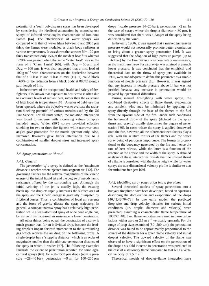
potential of a ‘real’ polydisperse spray has been developedby considering the idealised attenuation by monodispersesprays of infrared wavelengths characteristic of luminousflames [64]. The effectiveness of water sprays wascompared with that of water films between 0 and 2000mmthick; the flames were modelled as black body radiators atvarious temperatures. It was shown that a water film 100mmthick transmitted only 15% of the incident heat flux whereas,28% was passed when the same ‘water load’ was in theform of a ‘Class 1 mist’ [66], withDV10 � 50mm andDV90 � 100mm: It was also suggested that a mist load of100 g m23 with characteristics on the borderline betweenthat of a ‘Class 1’ and ‘Class 2’ mist (Fig. 7) could block,60% of the radiation from a black body at 8008C along apath length of 1 m.
In the context of the occupational health and safety of fire-fighters, it is known that exposure to heat stress is often dueto excessive levels of radiant heat, rather than the existenceof high local air temperatures [65]. A series of field tests hasbeen reported, where the objective was to evaluate the radia-tion-blocking potential of various nozzles used by the USFire Service. For all units tested, the radiation attenuationwas found to increase with increasing values of sprayincluded angle. Wider (908) sprays provided effectiveshielding for two or three fire-fighters while narrower coneangles gave protection for the nozzle operator only. Also,increased flowrates gave better attenuation due to acombination of smaller droplet sizes and increased sprayconcentration.
7.4. Spray penetration or ‘throw’
7.4.1. GeneralThe penetration of a sprayis defined as the ‘maximum
distance it reaches when injected into stagnant air’ [12]. Thegoverning factors are the relative magnitudes of the kineticenergy of the initial liquid jet and the degree of aerodynamicresistance offered by the surrounding gas. Although theinitial velocity of the jet is usually high, the ensuingbreak-up into droplets rapidly increases the surface area ofthe spray and the kinetic energy is gradually dissipated byfrictional losses. Thus, a combination of local air currentsand the force of gravity dictate the spray trajectory. Ingeneral, a compact narrow spray has a relatively high pene-tration while a well-atomised spray of wide cone angle has,by virtue of its increased air resistance, a lower penetration.
All other things being equal, the penetration of a spray ismuch greater than for an individual drop, because the lead-ing droplets impart forward momentum to the surroundinggas which reduces the air drag on the following drops. Asingle droplet has a ‘stopping distance’ which is an order ofmagnitude smaller than the ultimate penetration distance ofthe spray in which it resides [67]. The following examplesillustrate the extent of penetration reported for some agri-cultural sprays [68]: for 400–1500mm drops (nozzle pres-sure ,28–40 bar), penetration,9 m, for 100–200mm
drops (nozzle pressure 14–20 bar), penetration,2 m. Inthe case of sprays where the droplet diameter,80mm, itwas considered that there was a danger of the spray beingdeflected by the wind.
In the early 1960s, it was argued that a marked increase inpressure would not necessarily promote better atomisationor bring about a greater spray penetration [10]. It wassuggested that the adoption of high pressure pumps (up to,60 bar) by the Fire Service was completely unnecessary,as the maximum throw for a spray-jet was attained at a muchlower pressure. It was concluded that the empirical andtheoretical data on the throw of spray jets, available in1960, were not adequate to define this parameter as a simplefunction of nozzle pressure [10]. However, it was arguedthat any increase in nozzle pressure above 14 bar was notjustified because any increase in penetration would benegated by operational difficulties.
During manual fire-fighting with water sprays, thecombined dissipative effects of flame thrust, evaporationand ambient wind may be minimised by applying thespray directly through the base of the flames to the fuelfrom the upwind side of the fire. Under such conditionsthe horizontal throw of the spray (dictated by the spraythrust and gravity) usually determines the degree of pene-tration [69]. In cases where the spray is applied downwardonto the fire, however, all the aforementioned factors play arole, with the relative thrusts of the flames and the waterspray being of particular importance. The former is propor-tional to the buoyancy generated by the fire and hence therate of heat release, while the latter is a function of thereaction at the nozzle and the width of the spray. A detailedanalysis of these interactions reveals that the upward thrustof a flame is correlated with the flame height while for watersprays the non-dimensional velocity profile is similar to thatfor turbulent free jets [69].
7.4.2. Modelling spray penetration into a fire plumeSeveral theoretical models of spray penetration into a
buoyant fire plume have been developed, based on equationsdescribing the deceleration and evaporation of the drops[40,42,43,70–78]. In one early model, the predicteddrop size and drop velocity histories for various initialconditions (i.e. droplet diameter and velocity) werepresented, assuming a characteristic flame temperature of10008C [40]. Two flame velocities were used in these calcu-lations, either zero or 2.5 m s21 vertically upwards. For therange of drop sizes examined (50–500mm), the penetrationdistance was found to be approximately proportional to thesquare of the diameter for a given flame velocity and initialdroplet velocity. The upward velocity of the flame wasobserved to have a significant effect on the penetration ofthe drop; a six-fold increase in penetration was predicted inthe case of a stationary flame compared to that with a verti-cal velocity of 2.5 m s21.
Theoretical models of droplet–flame interaction have
G. Grant et al. / Progress in Energy and Combustion Science 26 (2000) 79–130 103
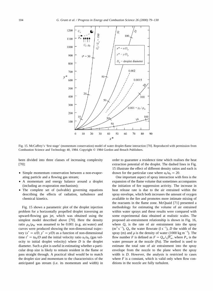
been divided into three classes of increasing complexity[70]:
• Simple momentum conservation between a non-evapor-ating particle and a flowing gas stream;
• A momentum and energy balance around a droplet(including an evaporation mechanism);
• The complete set of (solvable) governing equationsdescribing the effects of radiation, turbulence andchemical kinetics.
Fig. 15 shows a parametric plot of the droplet injectionproblem for a horizontally propelled droplet traversing anupward-flowing gas jet, which was obtained using thesimplest model described above [70]. Here the densityratio rA =rW was assumed to be 0.001 (e.g. air:water) andcurves were produced showing the non-dimensional trajec-tory �xp � x=D; yp � y=D� as a function of non-dimensionaltime tp � tu0=D and the initial velocity ratiouf =u0 (gas vel-ocity to initial droplet velocity) whereD is the dropletdiameter. Such a plot is useful in estimating whether a parti-cular drop size is likely to remain resident in the flame orpass straight through. A practical ideal would be to matchthe droplet size and momentum to the characteristics of theanticipated gas stream (i.e. its momentum and width) in
order to guarantee a residence time which realises the heatextraction potential of the droplet. The dashed lines in Fig.15 illustrate the effect of different density ratios and each isdrawn for the particular case whereuf =u0 � 20:
One important aspect of spray interaction with fires is theexpansion of the flame volume that sometimes accompaniesthe initiation of fire suppression activity. The increase inheat release rate is due to the air entrained within thespray envelope, which both increases the amount of oxygenavailable to the fire and promotes more intimate mixing ofthe reactants in the flame zone. McQuaid [71] presented amethodology for estimating the volume of air entrainedwithin water sprays and these results were compared withsome experimental data obtained at realistic scales. Theproposed air-entrainment relationship is shown in Fig. 16,where Qa is the rate of air entrainment into the spray(m3 s21), Qw the water flowrate (l s21), D the width of thespray (m) andr is the density of water (1000 kg m23). Theflow numberF is defined asF � Qw=
����Pwp
, wherePw is thewater pressure at the nozzle (Pa). The method is used toestimate the total rate of air entrainment into the sprayenvelope from the nozzle to the plane where the spraywidth is D. However, the analysis is restricted to caseswhereF is a constant, which is valid only when flow con-ditions in the nozzle are fully turbulent.
G. Grant et al. / Progress in Energy and Combustion Science 26 (2000) 79–130104
Fig. 15. McCaffrey’s ‘first stage’ (momentum conservation) model of water droplet-flame interaction [70]. Reproduced with permission fromCombustion Science and Technology 40, 1984. Copyrightq 1984 Gordon and Breach Publishers.
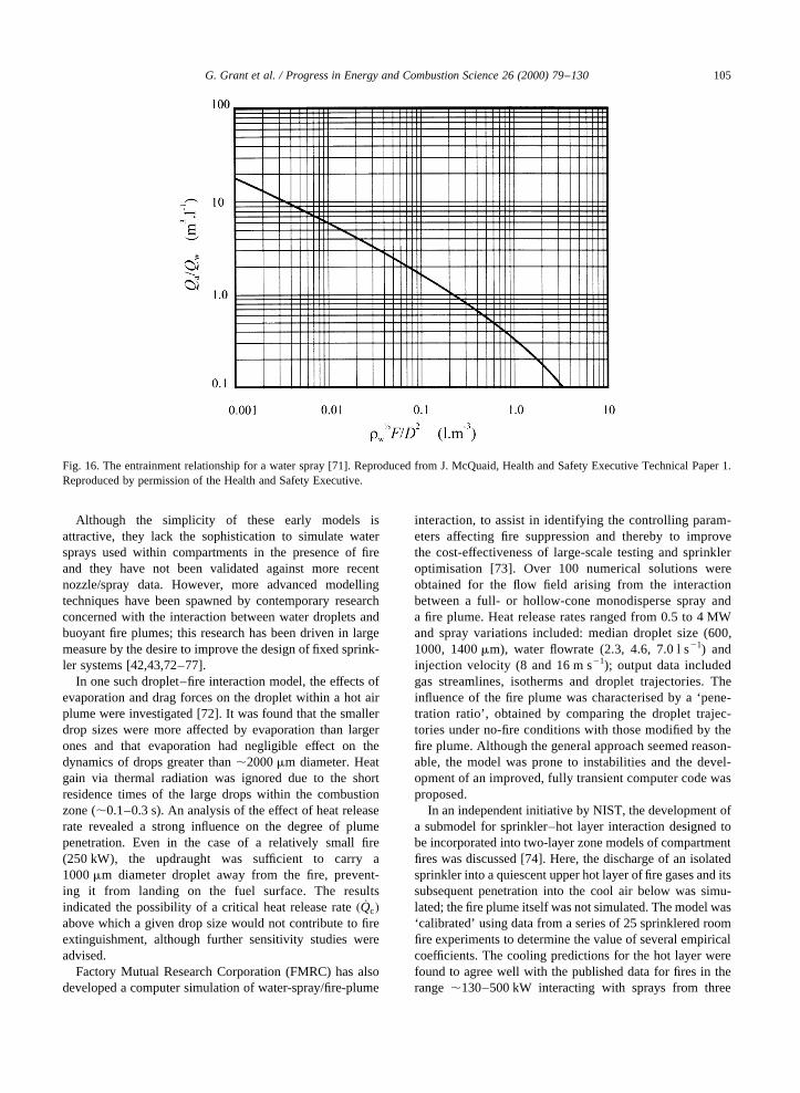
Although the simplicity of these early models isattractive, they lack the sophistication to simulate watersprays used within compartments in the presence of fireand they have not been validated against more recentnozzle/spray data. However, more advanced modellingtechniques have been spawned by contemporary researchconcerned with the interaction between water droplets andbuoyant fire plumes; this research has been driven in largemeasure by the desire to improve the design of fixed sprink-ler systems [42,43,72–77].
In one such droplet–fire interaction model, the effects ofevaporation and drag forces on the droplet within a hot airplume were investigated [72]. It was found that the smallerdrop sizes were more affected by evaporation than largerones and that evaporation had negligible effect on thedynamics of drops greater than,2000mm diameter. Heatgain via thermal radiation was ignored due to the shortresidence times of the large drops within the combustionzone (,0.1–0.3 s). An analysis of the effect of heat releaserate revealed a strong influence on the degree of plumepenetration. Even in the case of a relatively small fire(250 kW), the updraught was sufficient to carry a1000mm diameter droplet away from the fire, prevent-ing it from landing on the fuel surface. The resultsindicated the possibility of a critical heat release rate� _Qc�above which a given drop size would not contribute to fireextinguishment, although further sensitivity studies wereadvised.
Factory Mutual Research Corporation (FMRC) has alsodeveloped a computer simulation of water-spray/fire-plume
interaction, to assist in identifying the controlling param-eters affecting fire suppression and thereby to improvethe cost-effectiveness of large-scale testing and sprinkleroptimisation [73]. Over 100 numerical solutions wereobtained for the flow field arising from the interactionbetween a full- or hollow-cone monodisperse spray anda fire plume. Heat release rates ranged from 0.5 to 4 MWand spray variations included: median droplet size (600,1000, 1400mm), water flowrate (2.3, 4.6, 7.0 l s21) andinjection velocity (8 and 16 m s21); output data includedgas streamlines, isotherms and droplet trajectories. Theinfluence of the fire plume was characterised by a ‘pene-tration ratio’, obtained by comparing the droplet trajec-tories under no-fire conditions with those modified by thefire plume. Although the general approach seemed reason-able, the model was prone to instabilities and the devel-opment of an improved, fully transient computer code wasproposed.
In an independent initiative by NIST, the development ofa submodel for sprinkler–hot layer interaction designed tobe incorporated into two-layer zone models of compartmentfires was discussed [74]. Here, the discharge of an isolatedsprinkler into a quiescent upper hot layer of fire gases and itssubsequent penetration into the cool air below was simu-lated; the fire plume itself was not simulated. The model was‘calibrated’ using data from a series of 25 sprinklered roomfire experiments to determine the value of several empiricalcoefficients. The cooling predictions for the hot layer werefound to agree well with the published data for fires in therange ,130–500 kW interacting with sprays from three
G. Grant et al. / Progress in Energy and Combustion Science 26 (2000) 79–130 105
Fig. 16. The entrainment relationship for a water spray [71]. Reproduced from J. McQuaid, Health and Safety Executive Technical Paper 1.Reproduced by permission of the Health and Safety Executive.
different sprinkler nozzles at flowrates between,40 and100 l min21.
In the UK, the spray–plume interaction model‘SPLASH’ was developed to simulate the water delugeprotection of chemical plant installations subjected toexternal fire impingement [42]. Output data from thismodel include the total heat transfer from the fire gasesto the spray, the complete physical and thermal drophistories throughout the spray and the changing propertiesof the fire gases. In the simulations reported, the degree ofwater coverage was found to diminish with both increas-ing fire gas temperature and external wind velocity; theresults were also found to be in general agreement withexperimental investigations of LPG tank protection. Themathematical formulation of the ‘SPLASH’ code has beendescribed in more detail by Jackman et al. [43], togetherwith representative output data from 22 simulations of asprinklered corridor fire. For each simulation the ultimatefate of 12 044 individual drops was determined, enablingboth the percentage of water evaporated and the percen-tage of water reaching the interface between hot and coldgas layers to be estimated.
Hoffman and Galea also developed a three-dimensionaltwo-phase fire-sprinkler interaction model [75–77].Describing the mathematical basis for their model [76],these workers noted that in contrast to the compartmentfire growth problem, the subject of fire suppression hadreceived comparatively little attention from the modellingcommunity and therefore remained in a relatively primitivestate of development. A comparison of the model’s predic-tions with experimental data from a fire–sprinkler inter-action scenario showed the time-dependent gas temperaturesto be in reasonable agreement with the test data [75,77]. Itwas concluded that although the technique was still in its‘early days’, the model was capable of producing qualita-tively correct simulations of the fire–sprinkler interaction.Given the massive computational effort required to solvesuch problems, it was seen as essential that futureimplementations of such models should run on parallelcomputers.
Fthenakis et al. presented a computational model ofwater spray interaction with a gaseous plume in thecontext of absorbing and dispersing an accidental releaseof toxic gas (hydrofluoric acid) in the atmosphere [78].Again the fundamental equations for momentum, massand energy interchange between the gas and liquid phaseswere solved; the solution domain was two-dimensional inthis case and the effects of turbulence were also includedthrough modified laminar flow equations. The influence ofthe water droplets was examined in two distinct flowregions: a dense spray region close to the nozzle and asparse spray region where the droplet trajectories wereassumed to be separate. The dense spray region wasdefined as occurring where the drops occupied a signifi-cant fraction, f , of the volume of the gas-phase(e.g.f . 0:05� and droplet trajectories were closely
spaced. In this region, the expression,
CD
CDS� 1 1 3:5f �26�
was adopted to relate the drop drag coefficient (CD) to thesingle drop drag coefficient (CDS). In the sparse sprayregion further from the nozzle however, the droplet popu-lation is small and the motion of the gas induced bypreceding drops may reduce the overall resistance to thespray as described earlier. Previous research on sparsesprays had shown that for sprays consisting of 300mmdrops, the maximum expected decrease inCDS would be,30%; a reduction inCDS of 15% was adopted for thesprays modelled (consisting mostly of droplets in the100–200mm range).
The ability of the model to predict air entrainment intothe spray was also discussed; in order to produce anacceptable level of agreement between the model andexperimental data it was necessary to adjust two of theconstants in the turbulence model [78]. This highlights arecurring feature associated with such sophisticatedmodelling techniques: although they are based on thefundamental equations of fluid motion and are thus bynature ‘generally applicable’, the successful representa-tion of certain specific flow features often requires addi-tional ‘sub-models’. Confidence in the latter should first begained however, typically through ‘validation’ comparisonsagainst high-quality empirical data, preferably gleaned fromlarge-scale experiments.
The optimum representation of the drop size distributionof the spray was examined during sensitivity studies. It wasfound that for the nozzles being modelled (which produceddroplets in the range 50–700mm), input data based on onlyfive representative drop sizes were sufficient to producesolutions that were insensitive to this parameter. Using asingle mean size rather than a size distribution resulted indeviations in the range of 2–5%.
7.5. Concept of ‘optimum’ droplet size
Given the importance of droplet size in fire-fightingsprays, it is reasonable to ask whether there exists is anoptimum droplet size which should be sought in practice.In trying to answer this question, it is valuable to recall thethree main mechanisms for fire extinguishment by water:flame cooling, fuel cooling and inerting the atmospherethrough the production of water vapour. The benefits ofthermal radiation absorption in limiting the fire spread andameliorating the thermal stresses on fire-fighters must alsobe considered.
If only one of these factors dominated the process of firesuppression, then it might be possible to stipulate an opti-mum drop size. For example, if flame cooling were thesingle most important factor, then a fine spray would alwaysbe preferable, the large surface-area to volume ratio wouldpromote efficient heat transfer and droplet evaporation,
G. Grant et al. / Progress in Energy and Combustion Science 26 (2000) 79–130106

leading to speedy fire extinguishment. On the contrary, ifcooling the fuel bed was the primary objective, then acoarser spray would be a better choice in order to ensuredroplet penetration through the fire plume convectioncurrents. In this case however, a fine spray would alsobe desirable to protect fire-fighters from high levels ofthermal radiation. For deep-seated glowing fires, the useof so-called ‘hard jets’ has been recommended [10],because of their high kinetic energy and good penetrativequalities.
In practice, however, it is not always apparent which firesuppression mechanism is the most important and it islikely that the relative importance of the various mechan-isms will change as the fire-fighting operation progresses.Intuitively then, it would be surprising if a single drop sizewere found to be a panacea for all stages of the suppres-sion and extinguishment of fire, given the complexities offire dynamics and the physical and chemical interactionsinvolved. Given that the geometry, temperatures and gasvelocities involved in practice will be wide ranging, itcould be argued that the introduction of a range of dropsizes would be more effective in fire suppression.Although this argument has a certain ‘theoretical’ appeal,it is also convenient because practical spray populationscomprise a range of droplet sizes (although the distributionmay be skewed by the appropriate selection of nozzledesign).
Notwithstanding the above, optimum droplet sizes havebeen proposed periodically in the literature. An optimummean diameter ofd , 350mm has been suggested [10],based on maximising the droplet heat transfer number (a )by maximising the ratio of terminal velocity to dropletdiameter. However, a counter argument has been madethat the emphasis should more correctly be placed on maxi-mising the total quantity of heat transferred to a given spray(W), by minimising the mean droplet diameter and thusmaximising the total spray surface area. Gu¨ttler [54]proposed the use of high-pressure (,30 bar) fogs compris-ing very small initial droplet diameters (,70mm) with highinitial velocity ,80 m s21. These sprays were designed toundergo a rapid deceleration at the fire zone(u∞ , 0.1 m s21) to ensure a ‘residence time’ sufficient torealise their maximum cooling effect through completeevaporation. A similar optimum droplet diameter (75mm)has also been deduced from a theoretical analysis of the heattransfer between a monodisperse spray and a propagatinghigh-temperature explosion flame [79].
Computational data relating the rate of heat absorptionof a monodisperse spray to the initial droplet diameterhave been derived [80]. Strong ‘peaks’ were observed inthe plots of rate of heat absorption versus the initial dropletdiameter; the heat abstraction rate was observed to fallaway for diameters either larger or smaller than somecritical diameter. Based on this study, it was concludedthat initial droplet sizes in the range 300–900mmproduced the best extinguishing performance, but that
the optimum diameter depended on the distance betweenthe nozzle and the flame zone and the prevailing thermalenvironment.
When fuel cooling is required, the problems associatedwith bringing water to the seat of the fire must be considered[72]. It has been suggested that droplets smaller than,1000mm are ineffective in pre-wetting or extinguishinga fire larger than,250 kW because they suffer gross deflec-tion by the fire plume and do not contribute to fuel cooling.Conversely, droplets larger than 2000mm are able to pene-trate the plume effectively and undergo little evaporation inthe process; hence these larger drops are better able to reachthe hot fuel surface.
The interaction between water sprays and thermalradiation has also been discussed previously. For theinfrared wavelengths of interest,l , 1–10mm; the radi-ant attenuation has been found to be strongly correlatedwith droplet radius [61–65]. Clearly, a spray whosecharacteristics are suited to plume penetration and fuelbed cooling (i.e.d , 2000mm and above) will not becompatible with the provision of optimum radiationattenuation.
In a literature survey concerning the measurement of dropsize and its impact on the extinguishment of confined andunconfined fires [81], the mechanisms of fire extinguishmentand the techniques of fire-fighting were discussed; it wasobserved that different fire scenarios required differentfire-fighting tactics. In general however, the literaturesuggested that the primary strategy for extinguishing roomfires should be to cool the fuel rather than ‘smother’ theflame (oxygen displacement by water vapour); hence theability of the spray droplets to penetrate to the fuel surfacewas of paramount importance. For intense fires in confinedspaces, the initial strategy of directing the spray to the upperpart of the space from a low-level opening was advised. Theuse of this tactic maximises the amount of water convertedto vapour; the accompanying absorption of heat coupledwith the displacement of smoke was found to yield bettervisibility and hence better accessibility to the seat of thefire. As this type of fire is frequently under-ventilatedwhen fire-fighting commences, the possibility of indu-cing a backdraught-like event by air entrainment was alsostressed.
In conclusion then, the literature on fire suppression doesnot indicate a single optimum drop size for fire-fighting; fornormal operations the availability of a range of drop sizesbetween,300 and 2000mm is desirable. If the effectiveabsorption of thermal radiation is also required for shieldingpurposes, the optimum droplet sizes lie at the lower end ofthe range 1–100mm. Flexibility of fire-fighting tactics isimportant and an adjustable nozzle appears to have tacticaladvantages. In the case of fixed fire suppression systems,physiological factors are not relevant and the optimumspray character is governed by environmental parameterssuch as the hazard class, compartment geometry and venti-lation configuration etc.
G. Grant et al. / Progress in Energy and Combustion Science 26 (2000) 79–130 107
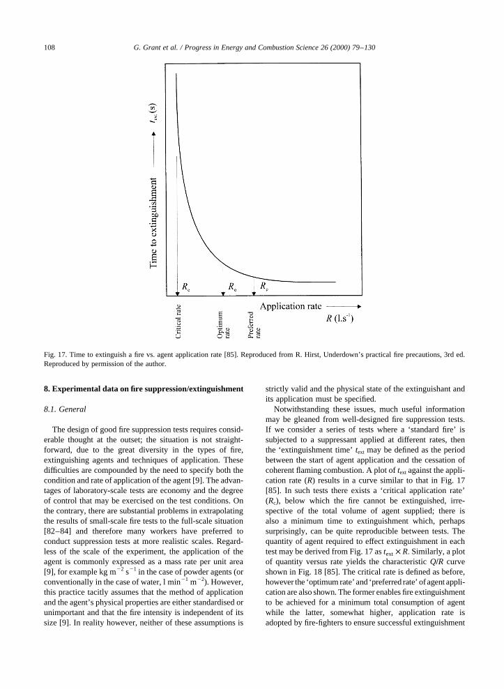
8. Experimental data on fire suppression/extinguishment
8.1. General
The design of good fire suppression tests requires consid-erable thought at the outset; the situation is not straight-forward, due to the great diversity in the types of fire,extinguishing agents and techniques of application. Thesedifficulties are compounded by the need to specify both thecondition and rate of application of the agent [9]. The advan-tages of laboratory-scale tests are economy and the degreeof control that may be exercised on the test conditions. Onthe contrary, there are substantial problems in extrapolatingthe results of small-scale fire tests to the full-scale situation[82–84] and therefore many workers have preferred toconduct suppression tests at more realistic scales. Regard-less of the scale of the experiment, the application of theagent is commonly expressed as a mass rate per unit area[9], for example kg m22 s21 in the case of powder agents (orconventionally in the case of water, l min21 m22). However,this practice tacitly assumes that the method of applicationand the agent’s physical properties are either standardised orunimportant and that the fire intensity is independent of itssize [9]. In reality however, neither of these assumptions is
strictly valid and the physical state of the extinguishant andits application must be specified.
Notwithstanding these issues, much useful informationmay be gleaned from well-designed fire suppression tests.If we consider a series of tests where a ‘standard fire’ issubjected to a suppressant applied at different rates, thenthe ‘extinguishment time’text may be defined as the periodbetween the start of agent application and the cessation ofcoherent flaming combustion. A plot oftext against the appli-cation rate (R) results in a curve similar to that in Fig. 17[85]. In such tests there exists a ‘critical application rate’(Rc), below which the fire cannot be extinguished, irre-spective of the total volume of agent supplied; there isalso a minimum time to extinguishment which, perhapssurprisingly, can be quite reproducible between tests. Thequantity of agent required to effect extinguishment in eachtest may be derived from Fig. 17 astext × R: Similarly, a plotof quantity versus rate yields the characteristicQ=R curveshown in Fig. 18 [85]. The critical rate is defined as before,however the ‘optimum rate’ and ‘preferred rate’ ofagent appli-cation are also shown. The former enables fire extinguishmentto be achieved for a minimum total consumption of agentwhile the latter, somewhat higher, application rate isadopted by fire-fighters to ensure successful extinguishment
G. Grant et al. / Progress in Energy and Combustion Science 26 (2000) 79–130108
Fig. 17. Time to extinguish a fire vs. agent application rate [85]. Reproduced from R. Hirst, Underdown’s practical fire precautions, 3rd ed.Reproduced by permission of the author.

in practice. Although the preferred rate may be some 3–4times greater thanRc and less economical than the optimumdelivery rate, the time to extinguishment is correspondinglyless (Fig. 17).
8.2. Nature of the ‘standard fire’
A standard fire source is a prerequisite for meaningfulinter-comparisons between various suppression agentsand application techniques. The standard fire has takenmany forms, including wooden cribs, pools of liquidfuels and even hi-rack arrangements of ‘typical’commodities stored in warehouses. Although many work-ers have devised their own standard fire in order to char-acterise a particular suppression problem, standards existin the US [86] and the UK [87] for the Class ‘A’ crib fire(Fig. 19). An important parameter for the standard cribfire is the total exposed fuel surface area, which may bederived from the stacking arrangement and the dimen-sions of the individual sticks. The standard cribsemployed in American studies are nominally square inplan but with varying heights (Fig. 19); for the exampleslisted in Table 7, the total exposed surface area may be
expressed as:
Ac � 2NSNL�wh1 hl 1 wl�2 2�NL 2 1��NSw�2 �27�whereNL andNS are the numbers of layers and sticks perlayer, respectively, andw, h, l are the width, height andlength of the individual sticks. This expression assumesthat the only unexposed wood occurs at the intersectionsof the sticks and that the crib is supported such that theobscured wood at its base is negligible.
The British Standard cribs are cuboid in shape and alwayscomprise 14 layers, therefore the surface area expression isdifferent:
Ac � 2:66�2l 1 38× 1023�1 0:364NS �28�The sticks used are nominally 38 mm square in cross-section and 500 mm long in the transverse direction (i.e.‘into the page’ in Fig. 19); longitudinal layers alwayscontain 5 sticks of lengthl, whilst the number of sticks intransverse layers,NS, is variable. The data for these cribs aregiven in Table 8.
Aside from the physical and chemical nature of the fuel,the burning behaviour of standard test fires depends onenvironmental factors such as the degree of confinement
G. Grant et al. / Progress in Energy and Combustion Science 26 (2000) 79–130 109
Fig. 18. Suppression agent quantity/rate curve [85]. Reproduced from R. Hirst, Underdown’s practical fire precautions, 3rd ed. Reproduced bypermission of the author.
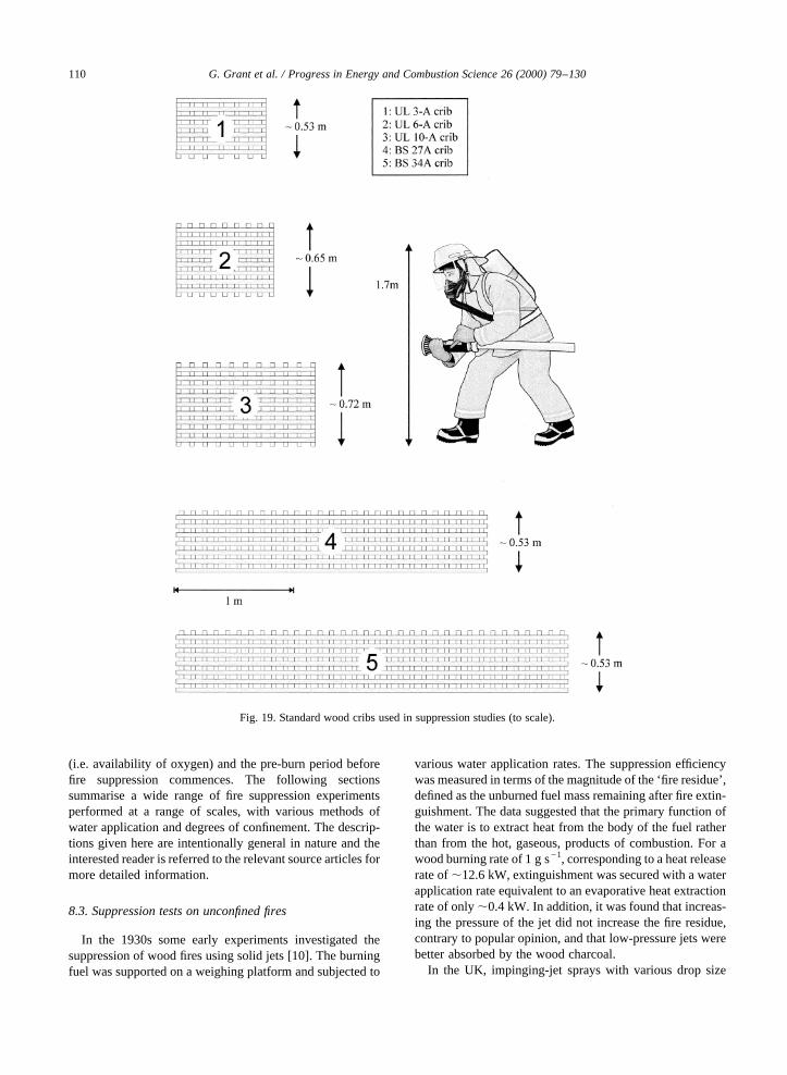
(i.e. availability of oxygen) and the pre-burn period beforefire suppression commences. The following sectionssummarise a wide range of fire suppression experimentsperformed at a range of scales, with various methods ofwater application and degrees of confinement. The descrip-tions given here are intentionally general in nature and theinterested reader is referred to the relevant source articles formore detailed information.
8.3. Suppression tests on unconfined fires
In the 1930s some early experiments investigated thesuppression of wood fires using solid jets [10]. The burningfuel was supported on a weighing platform and subjected to
various water application rates. The suppression efficiencywas measured in terms of the magnitude of the ‘fire residue’,defined as the unburned fuel mass remaining after fire extin-guishment. The data suggested that the primary function ofthe water is to extract heat from the body of the fuel ratherthan from the hot, gaseous, products of combustion. For awood burning rate of 1 g s21, corresponding to a heat releaserate of,12.6 kW, extinguishment was secured with a waterapplication rate equivalent to an evaporative heat extractionrate of only,0.4 kW. In addition, it was found that increas-ing the pressure of the jet did not increase the fire residue,contrary to popular opinion, and that low-pressure jets werebetter absorbed by the wood charcoal.
In the UK, impinging-jet sprays with various drop size
G. Grant et al. / Progress in Energy and Combustion Science 26 (2000) 79–130110
Fig. 19. Standard wood cribs used in suppression studies (to scale).

distributions were employed during extinguishment trialsinvolving 30 cm pan fires of alcohol, benzole, petrol, kero-sene (firepoint,60–688C), gas oil (firepoint,104–1158C)and transformer oil (firepoint,175–1808C) [88]. Fivedifferent sprays were employed, with volumetric meandiameters (D30) in the range 157–250mm, correspondingto Sauter mean diameters (D32 in Table 2) of 230–430mm, respectively. The pre-burn time for the liquidsvaried from 1 s to 8 min. The finer sprays promoted themost rapid extinguishment on volatile fuel fires (alcohol,petrol, benzole) whereas the coarser sprays were bettersuited to extinguishing the less volatile fuels (gas oil, trans-former oil). The results were analysed by correlating theextinguishment time (text) with properties of both the firesand the sprays. The most efficient sprays were found to bethose with the finest droplets, the highest rates of water flowand the highest velocities of entrained air.
The critical application rate for extinguishing wood fireswas determined in the US [89], from experiments involvinga burning wood crib constructed of 51 mm square sectionsof Corsican Pine (moisture content 12%) and with a totalsurface area of 7.2 m2. A single horizontal water spray wasdirected on the rotating burning crib and the time to extin-guishment was measured as a function of the applicationrate. The critical rate for extinguishment� _m00wc� was deter-mined to be 0.10 l min21 m22 for a 38% pre-burn (i.e. waterapplication commenced after the crib had lost 38% of its
initial mass) and it was concluded that the predominantextinguishment mechanism was fuel cooling.
More recently, a horizontal water spray was appliedmanually to two sides of a burning wooden (JapaneseCedar) crib [90] and _m00wc was found to be,0.15 l min21 m22. Experimental data have also beenreported from suppression tests on fires involving woodencribs (moisture content,0%) and wooden pallets (moisturecontents between 6 and 10%) [91]. The cribs comprisedsticks 17× 17× 185 mm with 4 sticks per layer (6, 11, or16). The wooden pallets were of volume 1.8 m3 and were ofa similar material. For the cribs,_m00wc varied from 0.11 to0.14 l min21 m22 for pre-burn values of 5 and 20%, re-spectively. For the fully involved pallet fires, a value for_m00wc , 0.15 l min21 m22 was determined for both 10 and20% pre-burns. Tamanini reported values for_m00wc of 0.09and 0.18 l min21 m22 for fires involving ‘loosely packed’and ‘densely packed’ cribs, respectively [92]; here thecribs were constructed from sticks of thickness 10, 13 and19 mm. In parallel suppression tests on small-scale slabs[93], with dimensions 191× 279 mm2 and thickness 6.4,12.7 and 19.1 mm, the critical application rate was_m00wc ,0:08 l min21 m22
:
Stolp observed that the critical delivery rate variesdepending upon the scale of the fire [94]; these data arereproduced in Table 9.
The discrepancies between the expected_m00wc obtained
G. Grant et al. / Progress in Energy and Combustion Science 26 (2000) 79–130 111
Table 8Wood crib fire dimensions to BS 5423 [87]
Standard testfire designation
No. of 500 mmsticks pertransverse layer,NS
Length of test firel (m) Total exposed fuelsurface area (m2)
3A 3 0.3 2.795A 5 0.5 4.588A 8 0.8 7.2713A 13 1.3 11.7521A 21 2.1 18.9227A 27 2.7 24.2934A 34 3.4 30.5743A 43 4.3 38.6355A 55 5.5 49.38
Table 7Wood crib fire dimensions to UL711 [86] (w� h� 0.038 m in all cases)
Standard testfire designation
No. of layers× no. of sticks,NL × NS
l (m) Total exposed fuelsurface area (m2)
1-A 10× 5 0.508 3.362-A 13× 6 0.651 6.703-A 14× 7 0.781 10.084-A 15× 8 0.848 13.236-A 17× 9 0.848 16.4210-A 19× 11 1.207 32.66
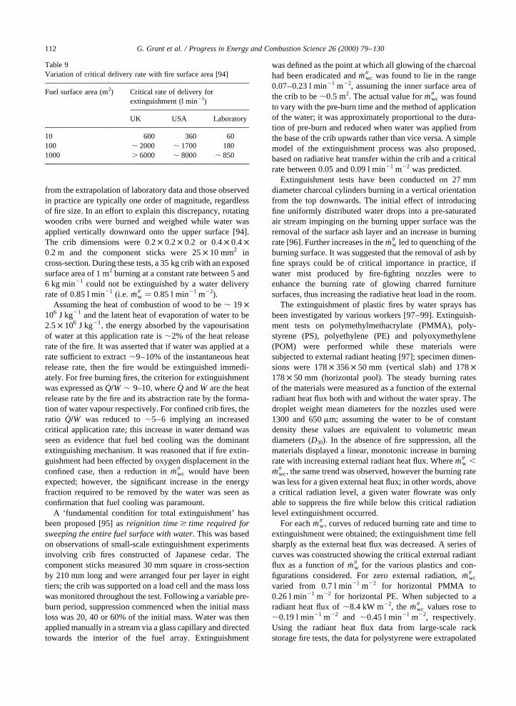
from the extrapolation of laboratory data and those observedin practice are typically one order of magnitude, regardlessof fire size. In an effort to explain this discrepancy, rotatingwooden cribs were burned and weighed while water wasapplied vertically downward onto the upper surface [94].The crib dimensions were 0:2 × 0:2 × 0:2 or 0:4 × 0:4 ×0:2 m and the component sticks were 25× 10 mm2 incross-section. During these tests, a 35 kg crib with an exposedsurface area of 1 m2 burning at a constant rate between 5 and6 kg min21 could not be extinguished by a water deliveryrate of 0.85 l min21 (i.e. _m00w � 0:85 l min21 m22).
Assuming the heat of combustion of wood to be, 19×106 J kg21 and the latent heat of evaporation of water to be2:5 × 10⁶ J kg21
; the energy absorbed by the vapourisationof water at this application rate is,2% of the heat releaserate of the fire. It was asserted that if water was applied at arate sufficient to extract,9–10% of the instantaneous heatrelease rate, then the fire would be extinguished immedi-ately. For free burning fires, the criterion for extinguishmentwas expressed as_Q= _W , 9–10; where _Q and _W are the heatrelease rate by the fire and its abstraction rate by the forma-tion of water vapour respectively. For confined crib fires, theratio _Q= _W was reduced to,5–6 implying an increasedcritical application rate; this increase in water demand wasseen as evidence that fuel bed cooling was the dominantextinguishing mechanism. It was reasoned that if fire extin-guishment had been effected by oxygen displacement in theconfined case, then a reduction in_m00wc would have beenexpected; however, the significant increase in the energyfraction required to be removed by the water was seen asconfirmation that fuel cooling was paramount.
A ‘fundamental condition for total extinguishment’ hasbeen proposed [95] asreignition time$ time required forsweeping the entire fuel surface with water. This was basedon observations of small-scale extinguishment experimentsinvolving crib fires constructed of Japanese cedar. Thecomponent sticks measured 30 mm square in cross-sectionby 210 mm long and were arranged four per layer in eighttiers; the crib was supported on a load cell and the mass losswas monitored throughout the test. Following a variable pre-burn period, suppression commenced when the initial massloss was 20, 40 or 60% of the initial mass. Water was thenapplied manually in a stream via a glass capillary and directedtowards the interior of the fuel array. Extinguishment
was defined as the point at which all glowing of the charcoalhad been eradicated and_m00wc was found to lie in the range0.07–0.23 l min21 m22, assuming the inner surface area ofthe crib to be,0.5 m2. The actual value for_m00wc was foundto vary with the pre-burn time and the method of applicationof the water; it was approximately proportional to the dura-tion of pre-burn and reduced when water was applied fromthe base of the crib upwards rather than vice versa. A simplemodel of the extinguishment process was also proposed,based on radiative heat transfer within the crib and a criticalrate between 0.05 and 0.09 l min21 m22 was predicted.
Extinguishment tests have been conducted on 27 mmdiameter charcoal cylinders burning in a vertical orientationfrom the top downwards. The initial effect of introducingfine uniformly distributed water drops into a pre-saturatedair stream impinging on the burning upper surface was theremoval of the surface ash layer and an increase in burningrate [96]. Further increases in the_m00w led to quenching of theburning surface. It was suggested that the removal of ash byfine sprays could be of critical importance in practice, ifwater mist produced by fire-fighting nozzles were toenhance the burning rate of glowing charred furnituresurfaces, thus increasing the radiative heat load in the room.
The extinguishment of plastic fires by water sprays hasbeen investigated by various workers [97–99]. Extinguish-ment tests on polymethylmethacrylate (PMMA), poly-styrene (PS), polyethylene (PE) and polyoxymethylene(POM) were performed while these materials weresubjected to external radiant heating [97]; specimen dimen-sions were 178× 356× 50 mm (vertical slab) and 178×178× 50 mm (horizontal pool). The steady burning ratesof the materials were measured as a function of the externalradiant heat flux both with and without the water spray. Thedroplet weight mean diameters for the nozzles used were1300 and 650mm; assuming the water to be of constantdensity these values are equivalent to volumetric meandiameters (D30). In the absence of fire suppression, all thematerials displayed a linear, monotonic increase in burningrate with increasing external radiant heat flux. Where_m00w ,_m00wc; the same trend was observed, however the burning ratewas less for a given external heat flux; in other words, abovea critical radiation level, a given water flowrate was onlyable to suppress the fire while below this critical radiationlevel extinguishment occurred.
For each _m00w; curves of reduced burning rate and time toextinguishment were obtained; the extinguishment time fellsharply as the external heat flux was decreased. A series ofcurves was constructed showing the critical external radiantflux as a function of _m00w for the various plastics and con-figurations considered. For zero external radiation,_m00wc
varied from 0.7 l min21 m22 for horizontal PMMA to0.26 l min21 m22 for horizontal PE. When subjected to aradiant heat flux of,8.4 kW m22, the _m00wc values rose to,0.19 l min21 m22 and ,0.45 l min21 m22, respectively.Using the radiant heat flux data from large-scale rackstorage fire tests, the data for polystyrene were extrapolated
G. Grant et al. / Progress in Energy and Combustion Science 26 (2000) 79–130112
Table 9Variation of critical delivery rate with fire surface area [94]
Fuel surface area (m2) Critical rate of delivery forextinguishment (l min21)
UK USA Laboratory
10 600 360 60100 , 2000 , 1700 1801000 . 6000 , 8000 , 850
to predict _m00wc under realistic conditions; at radiant fluxes of,63 kW m22, _m00wc , 1:07 l min21 m22
; some 10% of thedelivery of contemporary automatic sprinklers.
Another study considered the burning behaviour andsuppressibility of plastics arranged in three-dimensionalstructures [98]. Plastic rods (15 mm in diameter× 330 mmin length) were used to construct three-dimensional cribs;the plastics used were: PVC (polyvinyl chloride), PU(polyurethane), PC (Polycarbonate), PF (phenol formalde-hyde), PE (polyethylene), PMMA (polymethyl methacry-late), POM (polyoxymethylene), ABS (acrylonitrile–butadiene–styrene co-polymer) and PP (polypropylene).The rods were supported in 5 layers in a steel mesh framewith 6 rods per layer. Three foam plastics (PF, PS, PU), withand without flame-retardants, were also tested as rectangularsamples either singly (PU) or in small cribs (PF, PS).Following ignition of the test material, a pre-burn delay ofup to 5 min was allowed, prior to the application of waterfrom a spray nozzle located 900 mm above the surface of thesample.
For the crib tests, a graph of extinguishment time againstpre-burn time was plotted for_m00w , 15 l min21 m22; it wasconcluded that the extinguishment time was proportional tothe delay between ignition and the activation of the waterspray for all the materials tested. For the foam plastics,unretarded PF was found to burn ‘exactly like wood’ andthe exposed surfaces were easily extinguished, however thedeep-seated flames persisted until the rate of water applica-tion was increased. A solid water stream proved more effec-tive than a spray and this was attributed to the former’sability to penetrate deeper inside the densely packed fuelarray. In general, there were large differences in the extin-guishing behaviour of plastics fires due to their differentchemical and physical properties; a tentative ranking ofthe increasing difficulty of extinguishment placed a ‘woodfire’ between PMMA and POM. Low water application rateswere found only to ‘agitate’ the combustion and extinguish-ment was only possible above a certain critical rate.
The extinguishment of small samples of solid white pine�50× 50× 20 mm� has been compared with that of similarsized samples of PMMA and unretarded PS foam [99]. Thematerials were burned either in a horizontal orientation or at458 inclination beneath a conical radiant heater capable ofsupplying a heat flux of up to,25 kW m22 on the uppersurface of the sample [99]. After a preheating time of 1 min,the sample was ignited and following an additional 1 minpre-burn interval, a low pressure water spray was dischargedvertically downward through the central aperture in theheater. Two spray nozzles were selected, conforming to amist classification system proposed by other workers [66];the average droplet sizes were,200mm and between 400and 1000mm. The extinguishment time generally decreasedwith increasing water application rate, approaching anasymptotic value at higher_m00w; for a given _m00w; the timeto extinguishment was found to decrease with decreasingmean droplet diameter. Due to the short ‘residence time’
of the droplets in the flame zone, evaporation in the flamezone was deemed to be negligible; hence fuel coolingappeared to be the primary extinguishment mechanism. Itwas stressed however, that the droplets produced bycommercial mist systems would be much smaller thanthose in the experimental study (and the flame zone muchlarger), leading to longer residence times and more dropletevaporation in practice. It was concluded that, in full-scaleapplications, the primary action of mist systems would be tocool the combustion zone. Acknowledging the importanceof fuel cooling in Class ‘A’ fire extinguishment, it wasrecommended that future research should aim to character-ise the nature of the spray near the fuel surface in order toelucidate the complex heat transfer interactions in thatregion.
The performance of low flow water hosereel systems hasbeen investigated experimentally [100] in a series of extin-guishment tests, performed on various sizes of unconfinedwooden cribs of types UL 10-A, 6-A and 3-A. The masses ofthese test cribs were nominally 187, 96 and 57 kg, re-spectively, and no attempt was made to control the moisturecontent of the wood. The 15 m long by 1.9 cm diameter hardrubber hose was fitted with a variable pattern nozzle deliver-ing a nominal flowrate of 1.9 l s21. The crib was mounted onfour load cells and other instrumentation included standardvideo equipment, IR imaging and two radiometers.
After an initial pre-burn period of between 5 and 6 min,manual fire-fighting was commenced, initially from adistance of 1.8 m and then freely from any position; theonly restriction imposed was that water could not be appliedto the rear vertical face of the crib. Extinguishment wasconfirmed when visual inspection and IR imaging showedno flames or ‘hot spots’ respectively at any point in the crib.A total of 26 crib fire tests were conducted in this mannerand the average mass loss rates for the 10-A, 6-A and 3-Afires were 250–320, 158 and 94 g s21, respectively. Thehosereel system performance was assessed from graphs offire control time vs. nozzle pressure, radiation attenuationversus nozzle pressure and ‘water density to control’ (l m22)vs. application rate (l min21 m22). The application ratesemployed during the tests varied widely, from 1.02 (lowflow, large crib) to 10.2 l min21 m22 (high flow, smallcrib). The m00w value required to control the fires wasfound to be fairly constant, at,0.6–1.2 l m22, except inthe case of the larger fires where the lowest applicationrates were used (1.02–1.56 l min21 m22) or the nozzle wasoperated at,4.6 m from the fire (‘stand-off’ tactic). Forthese adverse cases, the range of application densityrequired wasm00w , 2.2–2.8 l m22. Overall, in terms of ef-ficiency of water usage, a minimum nozzle pressure of,1.5–2 bar and corresponding flowrate of,45–60 l min21
were recommended. For a nozzle flow of,115 l min21,pressures below,1.5 bar were not recommended and deliv-ery rates of,45–70 l min21 were provisionally recom-mended for fighting post-flashover compartment fires.
Preliminary studies of the effectiveness of low pressure
G. Grant et al. / Progress in Energy and Combustion Science 26 (2000) 79–130 113
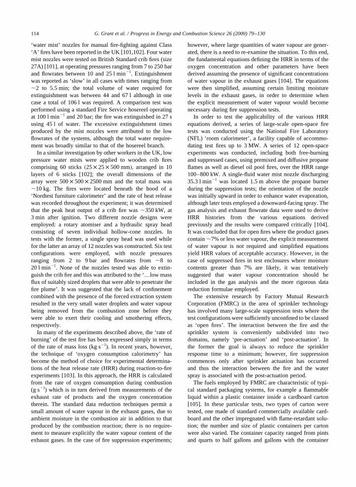
‘water mist’ nozzles for manual fire-fighting against Class‘A’ fires have been reported in the UK [101,102]. Four watermist nozzles were tested on British Standard crib fires (size27A) [101], at operating pressures ranging from 7 to 250 barand flowrates between 10 and 25 l min21. Extinguishmentwas reported as ‘slow’ in all cases with times ranging from,2 to 5.5 min; the total volume of water required forextinguishment was between 44 and 67 l although in onecase a total of 106 l was required. A comparison test wasperformed using a standard Fire Service hosereel operatingat 100 l min21 and 20 bar; the fire was extinguished in 27 susing 45 l of water. The excessive extinguishment timesproduced by the mist nozzles were attributed to the lowflowrates of the systems, although the total water require-ment was broadly similar to that of the hosereel branch.
In a similar investigation by other workers in the UK, lowpressure water mists were applied to wooden crib firescomprising 60 sticks�25× 25× 500 mm�; arranged in 10layers of 6 sticks [102]; the overall dimensions of thearray were 500× 500× 2500 mm and the total mass was,10 kg. The fires were located beneath the hood of a‘Nordtest furniture calorimeter’ and the rate of heat releasewas recorded throughout the experiment; it was determinedthat the peak heat output of a crib fire was,350 kW, at3 min after ignition. Two different nozzle designs wereemployed: a rotary atomiser and a hydraulic spray headconsisting of seven individual hollow-cone nozzles. Intests with the former, a single spray head was used whilefor the latter an array of 12 nozzles was constructed. Six testconfigurations were employed, with nozzle pressuresranging from 2 to 9 bar and flowrates from,8 to20 l min21. None of the nozzles tested was able to extin-guish the crib fire and this was attributed to the ‘…low massflux of suitably sized droplets that were able to penetrate thefire plume’. It was suggested that the lack of confinementcombined with the presence of the forced extraction systemresulted in the very small water droplets and water vapourbeing removed from the combustion zone before theywere able to exert their cooling and smothering effects,respectively.
In many of the experiments described above, the ‘rate ofburning’ of the test fire has been expressed simply in termsof the rate of mass loss (kg s21). In recent years, however,the technique of ‘oxygen consumption calorimetry’ hasbecome the method of choice for experimental determina-tions of the heat release rate (HRR) during reaction-to-fireexperiments [103]. In this approach, the HRR is calculatedfrom the rate of oxygen consumption during combustion(g s21) which is in turn derived from measurements of theexhaust rate of products and the oxygen concentrationtherein. The standard data reduction techniques permit asmall amount of water vapour in the exhaust gases, due toambient moisture in the combustion air in addition to thatproduced by the combustion reaction; there is no require-ment to measure explicitly the water vapour content of theexhaust gases. In the case of fire suppression experiments;
however, where large quantities of water vapour are gener-ated, there is a need to re-examine the situation. To this end,the fundamental equations defining the HRR in terms of theoxygen concentration and other parameters have beenderived assuming the presence of significant concentrationsof water vapour in the exhaust gases [104]. The equationswere then simplified, assuming certain limiting moisturelevels in the exhaust gases, in order to determine whenthe explicit measurement of water vapour would becomenecessary during fire suppression tests.
In order to test the applicability of the various HRRequations derived, a series of large-scale open-space firetests was conducted using the National Fire Laboratory(NFL) ‘room calorimeter’, a facility capable of accommo-dating test fires up to 3 MW. A series of 12 open-spaceexperiments was conducted, including both free-burningand suppressed cases, using premixed and diffusive propaneflames as well as diesel oil pool fires, over the HRR range100–800 kW. A single-fluid water mist nozzle discharging35.3 l min21 was located 1.5 m above the propane burnerduring the suppression tests; the orientation of the nozzlewas initially upward in order to enhance water evaporation,although later tests employed a downward-facing spray. Thegas analysis and exhaust flowrate data were used to deriveHRR histories from the various equations derivedpreviously and the results were compared critically [104].It was concluded that for open fires where the product gasescontain,7% or less water vapour, the explicit measurementof water vapour is not required and simplified equationsyield HRR values of acceptable accuracy. However, in thecase of suppressed fires in test enclosures where moisturecontents greater than 7% are likely, it was tentativelysuggested that water vapour concentration should beincluded in the gas analysis and the more rigorous datareduction formulae employed.
The extensive research by Factory Mutual ResearchCorporation (FMRC) in the area of sprinkler technologyhas involved many large-scale suppression tests where thetest configurations were sufficiently unconfined to be classedas ‘open fires’. The interaction between the fire and thesprinkler system is conveniently subdivided into twodomains, namely ‘pre-actuation’ and ‘post-actuation’. Inthe former the goal is always to reduce the sprinklerresponse time to a minimum; however, fire suppressioncommences only after sprinkler actuation has occurredand thus the interaction between the fire and the waterspray is associated with the post-actuation period.
The fuels employed by FMRC are characteristic of typi-cal standard packaging systems, for example a flammableliquid within a plastic container inside a cardboard carton[105]. In these particular tests, two types of carton weretested, one made of standard commercially available card-board and the other impregnated with flame-retardant solu-tion; the number and size of plastic containers per cartonwere also varied. The container capacity ranged from pintsand quarts to half gallons and gallons with the container
G. Grant et al. / Progress in Energy and Combustion Science 26 (2000) 79–130114
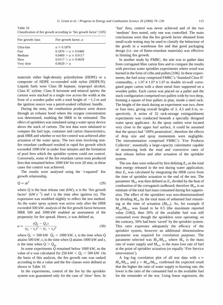
materials either high-density polyethylene (HDPE) or acomposite of HDPE co-extruded with nylon (HDPE/N).Liquids fuels were Class IB heptane, isopropyl alcohol,Class IC xylene, Class II kerosene and mineral spirits; thecartons were stacked in a single row across the width at thefront of a wooden pallet with a total height of,1.2 m andthe ignition source was a petrol-soaked cellulosic bundle.
During the tests, the combustion products were drawnthrough an exhaust hood where the oxygen concentrationwas determined, enabling the HRR to be estimated. Theeffect of sprinklers was simulated using a water spray deviceabove the stack of cartons. The test data were tabulated tocompare the fuel type, container and carton characteristics,peak HRR and whether or not fire control was achieved afteractuation of the water spray. The two tests involving non-fire retardant cardboard resulted in rapid fire growth whichexceeded 1000 kW in under four minutes and the formationof pool fires which the sprinkler system could not control.Conversely, some of the fire retardant carton tests producedfires that remained below 1000 kW for over 20 min; in thesecases fire control was achieved.
The results were analysed using the ‘t-squared’ firegrowth relationship,
_Q� at2 �29�where _Q is the heat release rate (kW),a is the ‘fire growthfactor’ (kW s22) and t is the time after ignition (s). Theexpression was modified slightly to reflect the test method.As the water spray system was active only after the HRRexceeded 500 kW, analysis of the fire growth factor betweenHRR 500 and 1000 kW enabled an assessment of thepropensity for fire spread. Hence,a was defined as,
a� � _Q2 2 _Q1��t2 2 ts�2 2 �t1 2 ts�2
�30�
where _Q1 � 500 kW _Q2 � 1000 kW; t1 is the time when_Qattains 500 kW,t2 is the time when_Q attains 1000 kW andtsis the time when_Q . _Qig:
In some experiments_Q remained below 1000 kW, so thevalue ofa was calculated for 250 kW, _Q2 , 500 kW: Onthe basis of this analysis, the fire growth rate was rankedaccording to thea value and the fire classes were defined asshown in Table 10.
In the experiments, control of the fire by the sprinklersystem was guaranteed only for the case of ‘slow’ fires. In
‘fast’ fires, control was never achieved and of the two‘medium’ fires tested, only one was controlled. The mainconclusions were that the fire growth factor obtained fromsmall-scale testing may be used to classify the behaviour ofthe goods in a warehouse fire and that good packagingdesign (i.e. use of flame-retardant materials) was effectivein limiting fire growth.
In another study by FMRC, the aim was to gather datafrom corrugated fibre carton fires and to compare the resultswith previous water sprinkler experiments where wood wasburned in the form of cribs and pallets [106]. In these experi-ments, the fuel array comprised FMRC’s ‘Standard Class II’commodity, a 1:07× 1:07× 1:07 m double tri-wall corru-gated paper carton with a sheet metal liner supported on awooden pallet. Each carton was placed on a pallet and thestack configuration comprised two pallets wide by two deep,forming a square of four pallets in plan, inside a steel rack.The height of the stack during an experiment was two, threeor four tiers, giving overall heights of 3, 4.5 and 6 m, re-spectively. A series of 32 rack-storage extinguishmentexperiments was conducted beneath a specially designedwater spray applicator. As the spray outlets were locatedvery close to the upper fuel surface, it could be assumedthat the sprays had ‘100% penetration’, therefore the effectsof drop size and spray momentum were negligible.The instrumentation comprised FMRC’s ‘Fire ProductsCollector’, essentially a large-capacity calorimeter capableof monitoring both the total and convective rates ofheat release before and after actuation of the sprinklersystem.
The raw data were reduced by first definingEw as the totalheat energy released in the test during water application;thusEw was calculated by integrating the HRR curve fromthe time of sprinkler actuation to the end of the test. TheparameterMext was then defined asEw divided by the heat ofcombustion of the corrugated cardboard; thereforeMext is anestimate of the total fuel mass consumed during fire suppres-sion. The effect of the sprinklers was non-dimensionalisedby dividing Mext by the total mass of unburned fuel remain-ing at the time of actuation (M0.w). So, for example ifMext=M0:w was found to be 0.5 (the maximum reportedvalue [106]), then 50% of the available fuel was stillconsumed even though the sprinklers were operating; onthe contrary, 50% had been ‘saved’ by the sprinkler system.This ratio expresses adequately the efficacy of thesprinkler system, however an additional dimensionlessparameter was required for correlation purposes. Theparameter selected was_Mw= _Mb:w where _Mw is the massrate of water supply and_Mb:w is the mass loss rate of fuelat the point of sprinkler actuation (or equally ‘Fire Serviceintervention’).
A log–log correlation plot of all test data withx�_Mw= _Mb:w andy� Mext=M0:w confirmed the expected result
that the higher the ratio of water supply to burning rate, thelower is the ratio of the consumed fuel to the available fuelfor the remainder of the test. Using linear regression, the
G. Grant et al. / Progress in Energy and Combustion Science 26 (2000) 79–130 115
Table 10Classification of fire growth according to ‘fire growth factor’ [105]
Fire growth class Fire growth factor,a
Ultra-fast a $ 0:1876Fast 0:1876. a $ 0:0469Medium 0:0469. a $ 0:0117Slow 0:0117. a $ 0:0029Very slow 0:0029. a
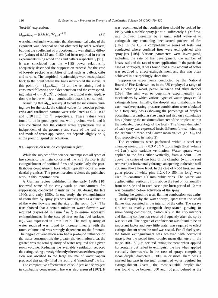
‘best-fit’ expression,
Mext=M0:w � 0:35� _Mw= _Mb:w�21:55 �31�was obtained and it was noted that the numerical value of theexponent was identical to that obtained by other workers,but that the coefficient of proportionality was slightly differ-ent (values of 0.312 and 0.150 had been reported in earlierexperiments using wood cribs and pallets respectively [91]).It was concluded that the21.55 power relationshipadequately described the suppression process for the caseof loosely packed assemblies of fuel such as pallets, cribsand cartons. The empirical relationships were extrapolatedback to the point where the lines intercepted thex-axis; atthis point �y� Mext=M0:w � 1� all the remaining fuel isconsumed following sprinkler actuation and the correspond-ing value ofx� _Mw= _Mb:w defines the critical water applica-tion rate below which all combustible mass is consumed.
Assuming that_Mb:w was equal to half the maximum burn-ing rate for the stack, the critical values for wooden pallets,cribs and cardboard cartons were calculated as 0.11, 0.13and 0.18 l min21 m22, respectively. These values werefound to be in good agreement with previous work, and itwas concluded that the critical water application rate isindependent of the geometry and scale of the fuel arrayand mode of water application, but depends slightly on_Qat the point of sprinkler actuation.
8.4. Suppression tests on compartment fires
While the subject of fire science encompasses all types offire scenario, the main concern of the Fire Service is theextinguishment of confined fires and particularly the post-flashover compartment fires which typically occur in resi-dential premises. The present section reviews the publishedwork in this important area.
A German review published in the early 1960s [10]reviewed some of the early work on compartment firesuppression, conducted mainly in the UK during the late1940s and early 1950s. In one study, the extinguishmentof room fires by spray jets was investigated as a functionof the water flowrate and the size of the room [107]. Thetests showed that a certain minimum water flowrate wasrequired (expressed in l min21 m23) to ensure successfulextinguishment; in the case of fires on flat fuel surfaces,_m00wc was expressed in l min21 m22. The total quantity ofwater required was found to increase linearly with theroom volume and was strongly dependent on the flowrate.The degree of ventilation also had a profound influence onthe water consumption; the greater the ventilation area, thegreater was the total quantity of water required for a givenroom volume. Reducing the available ventilation reducedthe extinguishing timesignificantly; the enhanced fire suppres-sion was ascribed to the large volume of water vapourproduced that rapidly filled the room and ‘smothered’ the fire.
The comparative effectiveness of solid jets and spray-jetsin combating compartment fire was also assessed [107]. It
was recommended that confined fires should be tackled in-itially with a mobile spray-jet at a ‘sufficiently high’ flow-rate followed thereafter by a small solid water-jet toextinguish any remaining deep-seated pockets of fire[107]. In the US, a comprehensive series of tests wasconducted where confined fires were extinguished withspray-jets [108]. Various parameters were investigated,including the rate of fire development, the number ofhoses used and the rate of water application. In the particularcase of spray-jets, it was found that a low amount of waterwas required to effect extinguishment and this was oftenachieved in a surprisingly short time.
Suppression experiments conducted by the NationalBoard of Fire Underwriters in the US employed a range offuels including wood, petrol, kerosene and ethyl alcohol[109]. The aim was to determine experimentally themechanisms by which various types of water sprays couldextinguish fires. Initially, the droplet size distributions foreach nozzle/operating pressure combination were tabulatedon a frequency basis (showing the percentage of dropletsoccurring in a particular size band) and also on a cumulativebasis (showing the maximum diameter of the droplets withinthe indicated percentage of the total). The ‘mean diameter’of each spray was expressed in six different forms, includingthe arithmetic mean and Sauter mean values (i.e.D10 andD32, respectively, in Table 2).
The experiments were performed within a steel testchamber measuring, 0:9 × 0:9 × 1:5 m high (total volume,1.2 m3) with variable ventilation. Water sprays wereapplied to the fires either vertically, from a point,3 mabove the centre of the base of the chamber (with the roofremoved) or horizontally through an opening in the side wall250 mm above floor level. In the case of wood fires, rectan-gular pieces of white pine�12× 6 × 150 mm long) wereused to construct 150 mm cubic cribs. The water wasapplied either vertically from above the fuel or horizontallyfrom one side and in each case a pre-burn period of 10 minwas permitted before activation of the spray.
During the wood fire tests, flaming combustion was extin-guished rapidly by the water sprays, apart from the smallflames that persisted in the interior of the cribs. The spraysdid not as readily extinguish deep-seated glowing orsmouldering combustion, particularly in the crib interiorsand flaming combustion recurred frequently after the spraywas shut off. The degree of confinement was found to be animportant factor and very little water was required to effectextinguishment when the roof was sealed. For all fuel types,the fastest extinguishment was achieved with horizontalsprays. For the petrol fires, droplet mean diameters in therange 100–150mm secured extinguishment when appliedhorizontally but failed to extinguish the fire when appliedvertically downwards. In the case of sprays comprisingmean droplet diameters,300mm or more, there was amarked increase in the total amount of water required forextinguishment. Overall, the ‘most suitable’ droplet sizewas found to be between 300 and 400mm, defined as the
G. Grant et al. / Progress in Energy and Combustion Science 26 (2000) 79–130116
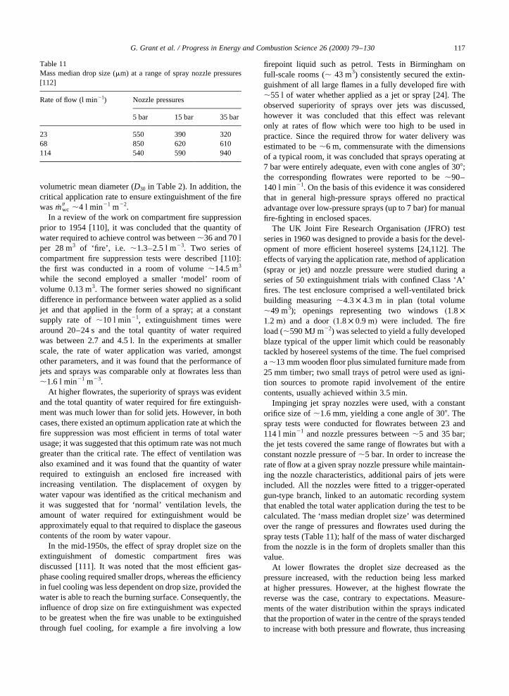
volumetric mean diameter (D30 in Table 2). In addition, thecritical application rate to ensure extinguishment of the firewas _m00wc ,4 l min21 m22.
In a review of the work on compartment fire suppressionprior to 1954 [110], it was concluded that the quantity ofwater required to achieve control was between,36 and 70 lper 28 m3 of ‘fire’, i.e. ,1.3–2.5 l m23. Two series ofcompartment fire suppression tests were described [110]:the first was conducted in a room of volume,14.5 m3
while the second employed a smaller ‘model’ room ofvolume 0.13 m3. The former series showed no significantdifference in performance between water applied as a solidjet and that applied in the form of a spray; at a constantsupply rate of,10 l min21, extinguishment times werearound 20–24 s and the total quantity of water requiredwas between 2.7 and 4.5 l. In the experiments at smallerscale, the rate of water application was varied, amongstother parameters, and it was found that the performance ofjets and sprays was comparable only at flowrates less than,1.6 l min21 m23.
At higher flowrates, the superiority of sprays was evidentand the total quantity of water required for fire extinguish-ment was much lower than for solid jets. However, in bothcases, there existed an optimum application rate at which thefire suppression was most efficient in terms of total waterusage; it was suggested that this optimum rate was not muchgreater than the critical rate. The effect of ventilation wasalso examined and it was found that the quantity of waterrequired to extinguish an enclosed fire increased withincreasing ventilation. The displacement of oxygen bywater vapour was identified as the critical mechanism andit was suggested that for ‘normal’ ventilation levels, theamount of water required for extinguishment would beapproximately equal to that required to displace the gaseouscontents of the room by water vapour.
In the mid-1950s, the effect of spray droplet size on theextinguishment of domestic compartment fires wasdiscussed [111]. It was noted that the most efficient gas-phase cooling required smaller drops, whereas the efficiencyin fuel cooling was less dependent on drop size, provided thewater is able to reach the burning surface. Consequently, theinfluence of drop size on fire extinguishment was expectedto be greatest when the fire was unable to be extinguishedthrough fuel cooling, for example a fire involving a low
firepoint liquid such as petrol. Tests in Birmingham onfull-scale rooms (, 43 m3) consistently secured the extin-guishment of all large flames in a fully developed fire with,55 l of water whether applied as a jet or spray [24]. Theobserved superiority of sprays over jets was discussed,however it was concluded that this effect was relevantonly at rates of flow which were too high to be used inpractice. Since the required throw for water delivery wasestimated to be,6 m, commensurate with the dimensionsof a typical room, it was concluded that sprays operating at7 bar were entirely adequate, even with cone angles of 308;the corresponding flowrates were reported to be,90–140 l min21. On the basis of this evidence it was consideredthat in general high-pressure sprays offered no practicaladvantage over low-pressure sprays (up to 7 bar) for manualfire-fighting in enclosed spaces.
The UK Joint Fire Research Organisation (JFRO) testseries in 1960 was designed to provide a basis for the devel-opment of more efficient hosereel systems [24,112]. Theeffects of varying the application rate, method of application(spray or jet) and nozzle pressure were studied during aseries of 50 extinguishment trials with confined Class ‘A’fires. The test enclosure comprised a well-ventilated brickbuilding measuring,4:3 × 4:3 m in plan (total volume,49 m3); openings representing two windows�1:8 ×1:2 m� and a door�1:8 × 0:9 m� were included. The fireload (,590 MJ m22) was selected to yield a fully developedblaze typical of the upper limit which could be reasonablytackled by hosereel systems of the time. The fuel compriseda,13 mm wooden floor plus simulated furniture made from25 mm timber; two small trays of petrol were used as igni-tion sources to promote rapid involvement of the entirecontents, usually achieved within 3.5 min.
Impinging jet spray nozzles were used, with a constantorifice size of,1.6 mm, yielding a cone angle of 308. Thespray tests were conducted for flowrates between 23 and114 l min21 and nozzle pressures between,5 and 35 bar;the jet tests covered the same range of flowrates but with aconstant nozzle pressure of,5 bar. In order to increase therate of flow at a given spray nozzle pressure while maintain-ing the nozzle characteristics, additional pairs of jets wereincluded. All the nozzles were fitted to a trigger-operatedgun-type branch, linked to an automatic recording systemthat enabled the total water application during the test to becalculated. The ‘mass median droplet size’ was determinedover the range of pressures and flowrates used during thespray tests (Table 11); half of the mass of water dischargedfrom the nozzle is in the form of droplets smaller than thisvalue.
At lower flowrates the droplet size decreased as thepressure increased, with the reduction being less markedat higher pressures. However, at the highest flowrate thereverse was the case, contrary to expectations. Measure-ments of the water distribution within the sprays indicatedthat the proportion of water in the centre of the sprays tendedto increase with both pressure and flowrate, thus increasing
G. Grant et al. / Progress in Energy and Combustion Science 26 (2000) 79–130 117
Table 11Mass median drop size (mm) at a range of spray nozzle pressures[112]
Rate of flow (l min21) Nozzle pressures
5 bar 15 bar 35 bar
23 550 390 32068 850 620 610114 540 590 940
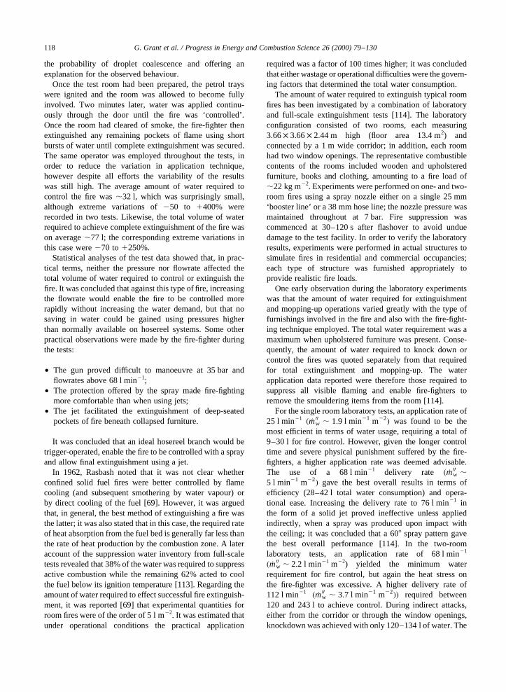
the probability of droplet coalescence and offering anexplanation for the observed behaviour.
Once the test room had been prepared, the petrol trayswere ignited and the room was allowed to become fullyinvolved. Two minutes later, water was applied continu-ously through the door until the fire was ‘controlled’.Once the room had cleared of smoke, the fire-fighter thenextinguished any remaining pockets of flame using shortbursts of water until complete extinguishment was secured.The same operator was employed throughout the tests, inorder to reduce the variation in application technique,however despite all efforts the variability of the resultswas still high. The average amount of water required tocontrol the fire was,32 l, which was surprisingly small,although extreme variations of250 to 1400% wererecorded in two tests. Likewise, the total volume of waterrequired to achieve complete extinguishment of the fire wason average,77 l; the corresponding extreme variations inthis case were270 to 1250%.
Statistical analyses of the test data showed that, in prac-tical terms, neither the pressure nor flowrate affected thetotal volume of water required to control or extinguish thefire. It was concluded that against this type of fire, increasingthe flowrate would enable the fire to be controlled morerapidly without increasing the water demand, but that nosaving in water could be gained using pressures higherthan normally available on hosereel systems. Some otherpractical observations were made by the fire-fighter duringthe tests:
• The gun proved difficult to manoeuvre at 35 bar andflowrates above 68 l min21;
• The protection offered by the spray made fire-fightingmore comfortable than when using jets;
• The jet facilitated the extinguishment of deep-seatedpockets of fire beneath collapsed furniture.
It was concluded that an ideal hosereel branch would betrigger-operated, enable the fire to be controlled with a sprayand allow final extinguishment using a jet.
In 1962, Rasbash noted that it was not clear whetherconfined solid fuel fires were better controlled by flamecooling (and subsequent smothering by water vapour) orby direct cooling of the fuel [69]. However, it was arguedthat, in general, the best method of extinguishing a fire wasthe latter; it was also stated that in this case, the required rateof heat absorption from the fuel bed is generally far less thanthe rate of heat production by the combustion zone. A lateraccount of the suppression water inventory from full-scaletests revealed that 38% of the water was required to suppressactive combustion while the remaining 62% acted to coolthe fuel below its ignition temperature [113]. Regarding theamount of water required to effect successful fire extinguish-ment, it was reported [69] that experimental quantities forroom fires were of the order of 5 l m22. It was estimated thatunder operational conditions the practical application
required was a factor of 100 times higher; it was concludedthat either wastage or operational difficulties were the govern-ing factors that determined the total water consumption.
The amount of water required to extinguish typical roomfires has been investigated by a combination of laboratoryand full-scale extinguishment tests [114]. The laboratoryconfiguration consisted of two rooms, each measuring3:66× 3:66× 2:44 m high (floor area 13.4 m2) andconnected by a 1 m wide corridor; in addition, each roomhad two window openings. The representative combustiblecontents of the rooms included wooden and upholsteredfurniture, books and clothing, amounting to a fire load of,22 kg m22. Experiments were performed on one- and two-room fires using a spray nozzle either on a single 25 mm‘booster line’ or a 38 mm hose line; the nozzle pressure wasmaintained throughout at 7 bar. Fire suppression wascommenced at 30–120 s after flashover to avoid unduedamage to the test facility. In order to verify the laboratoryresults, experiments were performed in actual structures tosimulate fires in residential and commercial occupancies;each type of structure was furnished appropriately toprovide realistic fire loads.
One early observation during the laboratory experimentswas that the amount of water required for extinguishmentand mopping-up operations varied greatly with the type offurnishings involved in the fire and also with the fire-fight-ing technique employed. The total water requirement was amaximum when upholstered furniture was present. Conse-quently, the amount of water required to knock down orcontrol the fires was quoted separately from that requiredfor total extinguishment and mopping-up. The waterapplication data reported were therefore those required tosuppress all visible flaming and enable fire-fighters toremove the smouldering items from the room [114].
For the single room laboratory tests, an application rate of25 l min21 � _m00w , 1:9 l min21 m22� was found to be themost efficient in terms of water usage, requiring a total of9–30 l for fire control. However, given the longer controltime and severe physical punishment suffered by the fire-fighters, a higher application rate was deemed advisable.The use of a 68 l min21 delivery rate � _m00w ,5 l min21 m22� gave the best overall results in terms ofefficiency (28–42 l total water consumption) and opera-tional ease. Increasing the delivery rate to 76 l min21 inthe form of a solid jet proved ineffective unless appliedindirectly, when a spray was produced upon impact withthe ceiling; it was concluded that a 608 spray pattern gavethe best overall performance [114]. In the two-roomlaboratory tests, an application rate of 68 l min21
� _m00w , 2.2 l min21 m22) yielded the minimum waterrequirement for fire control, but again the heat stress onthe fire-fighter was excessive. A higher delivery rate of112 l min21 � _m00w , 3:7 l min21 m22�� required between120 and 243 l to achieve control. During indirect attacks,either from the corridor or through the window openings,knockdown was achieved with only 120–134 l of water. The
G. Grant et al. / Progress in Energy and Combustion Science 26 (2000) 79–130118
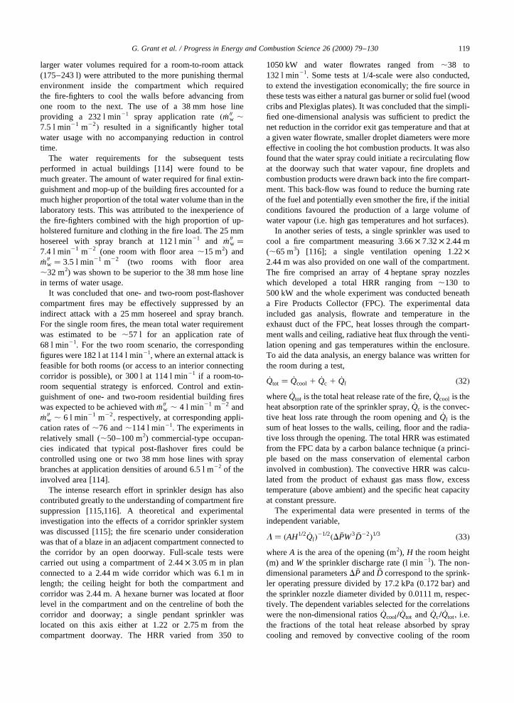
larger water volumes required for a room-to-room attack(175–243 l) were attributed to the more punishing thermalenvironment inside the compartment which requiredthe fire-fighters to cool the walls before advancing fromone room to the next. The use of a 38 mm hose lineproviding a 232 l min21 spray application rate� _m00w ,7:5 l min21 m22� resulted in a significantly higher totalwater usage with no accompanying reduction in controltime.
The water requirements for the subsequent testsperformed in actual buildings [114] were found to bemuch greater. The amount of water required for final extin-guishment and mop-up of the building fires accounted for amuch higher proportion of the total water volume than in thelaboratory tests. This was attributed to the inexperience ofthe fire-fighters combined with the high proportion of up-holstered furniture and clothing in the fire load. The 25 mmhosereel with spray branch at 112 l min21 and _m00w �7:4 l min21 m22 (one room with floor area,15 m2) and_m00w � 3:5 l min21 m22 (two rooms with floor area,32 m2) was shown to be superior to the 38 mm hose linein terms of water usage.
It was concluded that one- and two-room post-flashovercompartment fires may be effectively suppressed by anindirect attack with a 25 mm hosereel and spray branch.For the single room fires, the mean total water requirementwas estimated to be,57 l for an application rate of68 l min21. For the two room scenario, the correspondingfigures were 182 l at 114 l min21, where an external attack isfeasible for both rooms (or access to an interior connectingcorridor is possible), or 300 l at 114 l min21 if a room-to-room sequential strategy is enforced. Control and extin-guishment of one- and two-room residential building fireswas expected to be achieved with_m00w , 4 l min21 m22 and_m00w , 6 l min21 m22
; respectively, at corresponding appli-cation rates of,76 and,114 l min21. The experiments inrelatively small (,50–100 m2) commercial-type occupan-cies indicated that typical post-flashover fires could becontrolled using one or two 38 mm hose lines with spraybranches at application densities of around 6.5 l m22 of theinvolved area [114].
The intense research effort in sprinkler design has alsocontributed greatly to the understanding of compartment firesuppression [115,116]. A theoretical and experimentalinvestigation into the effects of a corridor sprinkler systemwas discussed [115]; the fire scenario under considerationwas that of a blaze in an adjacent compartment connected tothe corridor by an open doorway. Full-scale tests werecarried out using a compartment of 2:44× 3:05 m in planconnected to a 2.44 m wide corridor which was 6.1 m inlength; the ceiling height for both the compartment andcorridor was 2.44 m. A hexane burner was located at floorlevel in the compartment and on the centreline of both thecorridor and doorway; a single pendant sprinkler waslocated on this axis either at 1.22 or 2.75 m from thecompartment doorway. The HRR varied from 350 to
1050 kW and water flowrates ranged from,38 to132 l min21. Some tests at 1/4-scale were also conducted,to extend the investigation economically; the fire source inthese tests was either a natural gas burner or solid fuel (woodcribs and Plexiglas plates). It was concluded that the simpli-fied one-dimensional analysis was sufficient to predict thenet reduction in the corridor exit gas temperature and that ata given water flowrate, smaller droplet diameters were moreeffective in cooling the hot combustion products. It was alsofound that the water spray could initiate a recirculating flowat the doorway such that water vapour, fine droplets andcombustion products were drawn back into the fire compart-ment. This back-flow was found to reduce the burning rateof the fuel and potentially even smother the fire, if the initialconditions favoured the production of a large volume ofwater vapour (i.e. high gas temperatures and hot surfaces).
In another series of tests, a single sprinkler was used tocool a fire compartment measuring 3:66× 7:32× 2:44 m(,65 m3) [116]; a single ventilation opening 1:22×2:44 m was also provided on one wall of the compartment.The fire comprised an array of 4 heptane spray nozzleswhich developed a total HRR ranging from,130 to500 kW and the whole experiment was conducted beneatha Fire Products Collector (FPC). The experimental dataincluded gas analysis, flowrate and temperature in theexhaust duct of the FPC, heat losses through the compart-ment walls and ceiling, radiative heat flux through the venti-lation opening and gas temperatures within the enclosure.To aid the data analysis, an energy balance was written forthe room during a test,
_Qtot � _Qcool 1 _Qc 1 _Ql �32�where _Qtot is the total heat release rate of the fire,_Qcool is theheat absorption rate of the sprinkler spray,_Qc is the convec-tive heat loss rate through the room opening and_Ql is thesum of heat losses to the walls, ceiling, floor and the radia-tive loss through the opening. The total HRR was estimatedfrom the FPC data by a carbon balance technique (a princi-ple based on the mass conservation of elemental carboninvolved in combustion). The convective HRR was calcu-lated from the product of exhaust gas mass flow, excesstemperature (above ambient) and the specific heat capacityat constant pressure.
The experimental data were presented in terms of theindependent variable,
L � �AH1=2 _Ql�21=2�D �PW3 �D22�1=3 �33�whereA is the area of the opening (m2), H the room height(m) andW the sprinkler discharge rate (l min21). The non-dimensional parametersD �P and �D correspond to the sprink-ler operating pressure divided by 17.2 kPa (0.172 bar) andthe sprinkler nozzle diameter divided by 0.0111 m, respec-tively. The dependent variables selected for the correlationswere the non-dimensional ratios_Qcool= _Qtot and _Qc= _Qtot; i.e.the fractions of the total heat release absorbed by spraycooling and removed by convective cooling of the room
G. Grant et al. / Progress in Energy and Combustion Science 26 (2000) 79–130 119
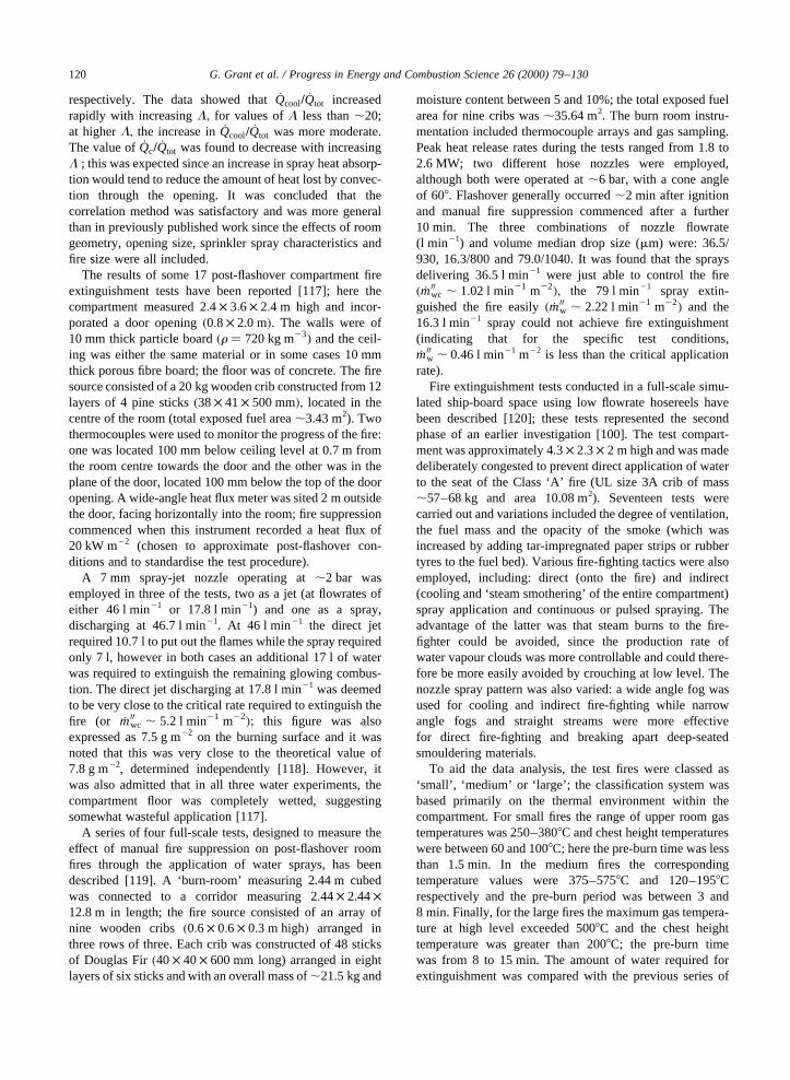
respectively. The data showed that_Qcool= _Qtot increasedrapidly with increasingL; for values ofL less than,20;at higherL; the increase in_Qcool= _Qtot was more moderate.The value of _Qc= _Qtot was found to decrease with increasingL ; this was expected since an increase in spray heat absorp-tion would tend to reduce the amount of heat lost by convec-tion through the opening. It was concluded that thecorrelation method was satisfactory and was more generalthan in previously published work since the effects of roomgeometry, opening size, sprinkler spray characteristics andfire size were all included.
The results of some 17 post-flashover compartment fireextinguishment tests have been reported [117]; here thecompartment measured 2:4 × 3:6 × 2:4 m high and incor-porated a door opening�0:8 × 2:0 m�: The walls were of10 mm thick particle board�r � 720 kg m23� and the ceil-ing was either the same material or in some cases 10 mmthick porous fibre board; the floor was of concrete. The firesource consisted of a 20 kg wooden crib constructed from 12layers of 4 pine sticks�38× 41× 500 mm�; located in thecentre of the room (total exposed fuel area,3.43 m2). Twothermocouples were used to monitor the progress of the fire:one was located 100 mm below ceiling level at 0.7 m fromthe room centre towards the door and the other was in theplane of the door, located 100 mm below the top of the dooropening. A wide-angle heat flux meter was sited 2 m outsidethe door, facing horizontally into the room; fire suppressioncommenced when this instrument recorded a heat flux of20 kW m22 (chosen to approximate post-flashover con-ditions and to standardise the test procedure).
A 7 mm spray-jet nozzle operating at,2 bar wasemployed in three of the tests, two as a jet (at flowrates ofeither 46 l min21 or 17.8 l min21) and one as a spray,discharging at 46.7 l min21. At 46 l min21 the direct jetrequired 10.7 l to put out the flames while the spray requiredonly 7 l, however in both cases an additional 17 l of waterwas required to extinguish the remaining glowing combus-tion. The direct jet discharging at 17.8 l min21 was deemedto be very close to the critical rate required to extinguish thefire (or _m00wc , 5:2 l min21 m22�; this figure was alsoexpressed as 7.5 g m22 on the burning surface and it wasnoted that this was very close to the theoretical value of7.8 g m22, determined independently [118]. However, itwas also admitted that in all three water experiments, thecompartment floor was completely wetted, suggestingsomewhat wasteful application [117].
A series of four full-scale tests, designed to measure theeffect of manual fire suppression on post-flashover roomfires through the application of water sprays, has beendescribed [119]. A ‘burn-room’ measuring 2.44 m cubedwas connected to a corridor measuring 2:44× 2:44×12:8 m in length; the fire source consisted of an array ofnine wooden cribs�0:6 × 0:6 × 0:3 m high� arranged inthree rows of three. Each crib was constructed of 48 sticksof Douglas Fir�40× 40× 600 mm long) arranged in eightlayers of six sticks and with an overall mass of,21.5 kg and
moisture content between 5 and 10%; the total exposed fuelarea for nine cribs was,35.64 m2. The burn room instru-mentation included thermocouple arrays and gas sampling.Peak heat release rates during the tests ranged from 1.8 to2.6 MW; two different hose nozzles were employed,although both were operated at,6 bar, with a cone angleof 608. Flashover generally occurred,2 min after ignitionand manual fire suppression commenced after a further10 min. The three combinations of nozzle flowrate(l min21) and volume median drop size (mm) were: 36.5/930, 16.3/800 and 79.0/1040. It was found that the spraysdelivering 36.5 l min21 were just able to control the fire� _m00wc , 1:02 l min21 m22�; the 79 l min21 spray extin-guished the fire easily� _m00w , 2:22 l min21 m22� and the16.3 l min21 spray could not achieve fire extinguishment(indicating that for the specific test conditions,_m00w , 0.46 l min21 m22 is less than the critical applicationrate).
Fire extinguishment tests conducted in a full-scale simu-lated ship-board space using low flowrate hosereels havebeen described [120]; these tests represented the secondphase of an earlier investigation [100]. The test compart-ment was approximately 4:3 × 2:3 × 2 m high and was madedeliberately congested to prevent direct application of waterto the seat of the Class ‘A’ fire (UL size 3A crib of mass,57–68 kg and area 10.08 m2). Seventeen tests werecarried out and variations included the degree of ventilation,the fuel mass and the opacity of the smoke (which wasincreased by adding tar-impregnated paper strips or rubbertyres to the fuel bed). Various fire-fighting tactics were alsoemployed, including: direct (onto the fire) and indirect(cooling and ‘steam smothering’ of the entire compartment)spray application and continuous or pulsed spraying. Theadvantage of the latter was that steam burns to the fire-fighter could be avoided, since the production rate ofwater vapour clouds was more controllable and could there-fore be more easily avoided by crouching at low level. Thenozzle spray pattern was also varied: a wide angle fog wasused for cooling and indirect fire-fighting while narrowangle fogs and straight streams were more effectivefor direct fire-fighting and breaking apart deep-seatedsmouldering materials.
To aid the data analysis, the test fires were classed as‘small’, ‘medium’ or ‘large’; the classification system wasbased primarily on the thermal environment within thecompartment. For small fires the range of upper room gastemperatures was 250–3808C and chest height temperatureswere between 60 and 1008C; here the pre-burn time was lessthan 1.5 min. In the medium fires the correspondingtemperature values were 375–5758C and 120–1958Crespectively and the pre-burn period was between 3 and8 min. Finally, for the large fires the maximum gas tempera-ture at high level exceeded 5008C and the chest heighttemperature was greater than 2008C; the pre-burn timewas from 8 to 15 min. The amount of water required forextinguishment was compared with the previous series of
G. Grant et al. / Progress in Energy and Combustion Science 26 (2000) 79–130120
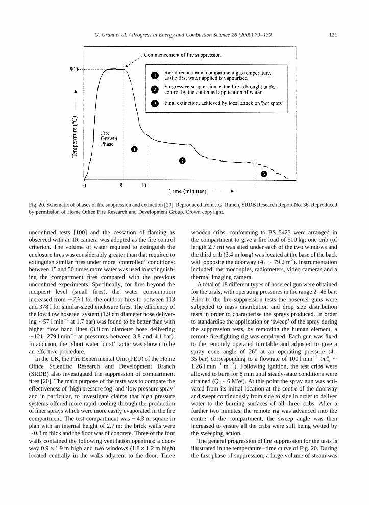
unconfined tests [100] and the cessation of flaming asobserved with an IR camera was adopted as the fire controlcriterion. The volume of water required to extinguish theenclosure fires was considerably greater than that required toextinguish similar fires under more ‘controlled’ conditions;between 15 and 50 times more water was used in extinguish-ing the compartment fires compared with the previousunconfined experiments. Specifically, for fires beyond theincipient level (small fires), the water consumptionincreased from,7.6 l for the outdoor fires to between 113and 378 l for similar-sized enclosure fires. The efficiency ofthe low flow hosereel system (1.9 cm diameter hose deliver-ing ,57 l min21 at 1.7 bar) was found to be better than withhigher flow hand lines (3.8 cm diameter hose delivering,121–279 l min21 at pressures between 3.8 and 4.1 bar).In addition, the ‘short water burst’ tactic was shown to bean effective procedure.
In the UK, the Fire Experimental Unit (FEU) of the HomeOffice Scientific Research and Development Branch(SRDB) also investigated the suppression of compartmentfires [20]. The main purpose of the tests was to compare theeffectiveness of ‘high pressure fog’ and ‘low pressure spray’and in particular, to investigate claims that high pressuresystems offered more rapid cooling through the productionof finer sprays which were more easily evaporated in the firecompartment. The test compartment was,4.3 m square inplan with an internal height of 2.7 m; the brick walls were,0.3 m thick and the floor was of concrete. Three of the fourwalls contained the following ventilation openings: a door-way 0:9 × 1:9 m high and two windows�1:8 × 1:2 m high)located centrally in the walls adjacent to the door. Three
wooden cribs, conforming to BS 5423 were arranged inthe compartment to give a fire load of 500 kg; one crib (oflength 2.7 m) was sited under each of the two windows andthe third crib (3.4 m long) was located at the base of the backwall opposite the doorway�Af , 79:2 m2�: Instrumentationincluded: thermocouples, radiometers, video cameras and athermal imaging camera.
A total of 18 different types of hosereel gun were obtainedfor the trials, with operating pressures in the range 2–45 bar.Prior to the fire suppression tests the hosereel guns weresubjected to mass distribution and drop size distributiontests in order to characterise the sprays produced. In orderto standardise the application or ‘sweep’ of the spray duringthe suppression tests, by removing the human element, aremote fire-fighting rig was employed. Each gun was fixedto the remotely operated turntable and adjusted to give aspray cone angle of 268 at an operating pressure (4–35 bar) corresponding to a flowrate of 100 l min21 � _m00w ,1:26 l min21 m22�: Following ignition, the test cribs wereallowed to burn for 8 min until steady-state conditions wereattained� _Q , 6 MW�: At this point the spray gun was acti-vated from its initial location at the centre of the doorwayand swept continuously from side to side in order to deliverwater to the burning surfaces of all three cribs. After afurther two minutes, the remote rig was advanced into thecentre of the compartment; the sweep angle was thenincreased to ensure all the cribs were still being wetted bythe sweeping action.
The general progression of fire suppression for the tests isillustrated in the temperature–time curve of Fig. 20. Duringthe first phase of suppression, a large volume of steam was
G. Grant et al. / Progress in Energy and Combustion Science 26 (2000) 79–130 121
Fig. 20. Schematic of phases of fire suppression and extinction [20]. Reproduced from J.G. Rimen, SRDB Research Report No. 36. Reproducedby permission of Home Office Fire Research and Development Group. Crown copyright.
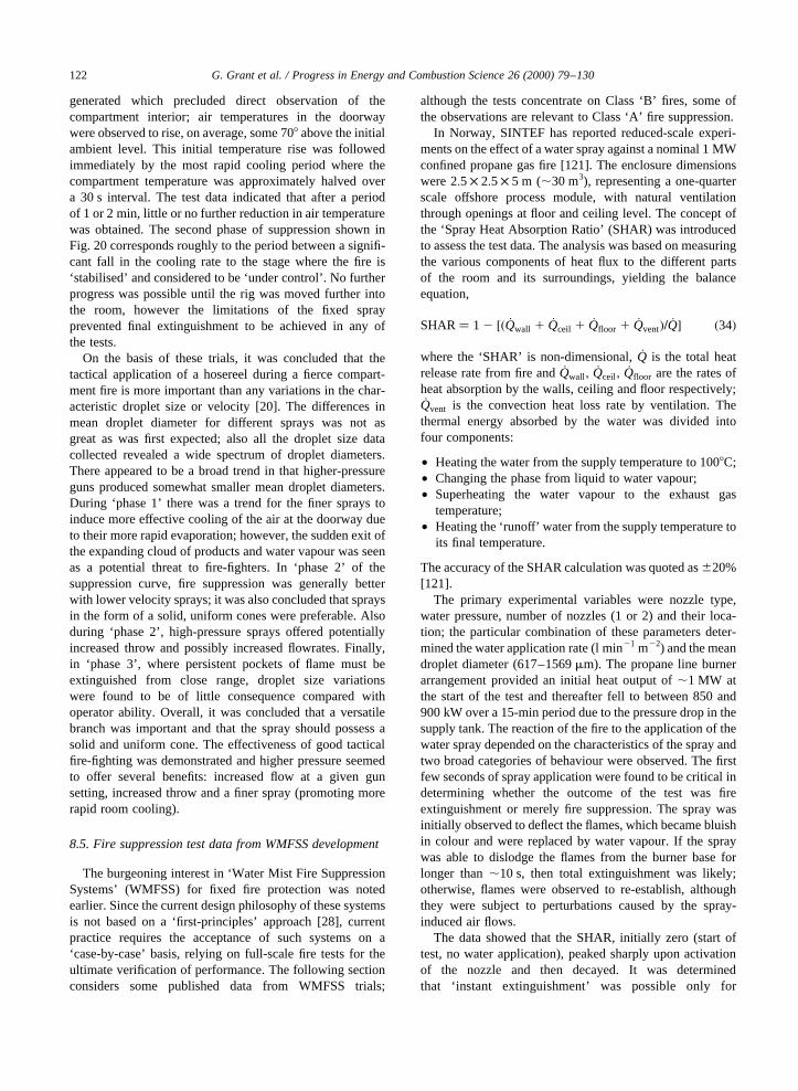
generated which precluded direct observation of thecompartment interior; air temperatures in the doorwaywere observed to rise, on average, some 708 above the initialambient level. This initial temperature rise was followedimmediately by the most rapid cooling period where thecompartment temperature was approximately halved overa 30 s interval. The test data indicated that after a periodof 1 or 2 min, little or no further reduction in air temperaturewas obtained. The second phase of suppression shown inFig. 20 corresponds roughly to the period between a signifi-cant fall in the cooling rate to the stage where the fire is‘stabilised’ and considered to be ‘under control’. No furtherprogress was possible until the rig was moved further intothe room, however the limitations of the fixed sprayprevented final extinguishment to be achieved in any ofthe tests.
On the basis of these trials, it was concluded that thetactical application of a hosereel during a fierce compart-ment fire is more important than any variations in the char-acteristic droplet size or velocity [20]. The differences inmean droplet diameter for different sprays was not asgreat as was first expected; also all the droplet size datacollected revealed a wide spectrum of droplet diameters.There appeared to be a broad trend in that higher-pressureguns produced somewhat smaller mean droplet diameters.During ‘phase 1’ there was a trend for the finer sprays toinduce more effective cooling of the air at the doorway dueto their more rapid evaporation; however, the sudden exit ofthe expanding cloud of products and water vapour was seenas a potential threat to fire-fighters. In ‘phase 2’ of thesuppression curve, fire suppression was generally betterwith lower velocity sprays; it was also concluded that spraysin the form of a solid, uniform cones were preferable. Alsoduring ‘phase 2’, high-pressure sprays offered potentiallyincreased throw and possibly increased flowrates. Finally,in ‘phase 3’, where persistent pockets of flame must beextinguished from close range, droplet size variationswere found to be of little consequence compared withoperator ability. Overall, it was concluded that a versatilebranch was important and that the spray should possess asolid and uniform cone. The effectiveness of good tacticalfire-fighting was demonstrated and higher pressure seemedto offer several benefits: increased flow at a given gunsetting, increased throw and a finer spray (promoting morerapid room cooling).
8.5. Fire suppression test data from WMFSS development
The burgeoning interest in ‘Water Mist Fire SuppressionSystems’ (WMFSS) for fixed fire protection was notedearlier. Since the current design philosophy of these systemsis not based on a ‘first-principles’ approach [28], currentpractice requires the acceptance of such systems on a‘case-by-case’ basis, relying on full-scale fire tests for theultimate verification of performance. The following sectionconsiders some published data from WMFSS trials;
although the tests concentrate on Class ‘B’ fires, some ofthe observations are relevant to Class ‘A’ fire suppression.
In Norway, SINTEF has reported reduced-scale experi-ments on the effect of a water spray against a nominal 1 MWconfined propane gas fire [121]. The enclosure dimensionswere 2:5 × 2:5 × 5 m (,30 m3), representing a one-quarterscale offshore process module, with natural ventilationthrough openings at floor and ceiling level. The concept ofthe ‘Spray Heat Absorption Ratio’ (SHAR) was introducedto assess the test data. The analysis was based on measuringthe various components of heat flux to the different partsof the room and its surroundings, yielding the balanceequation,
SHAR� 1 2 �� _Qwall 1 _Qceil 1 _Qfloor 1 _Qvent�= _Q� �34�
where the ‘SHAR’ is non-dimensional,_Q is the total heatrelease rate from fire and_Qwall; _Qceil; _Qfloor are the rates ofheat absorption by the walls, ceiling and floor respectively;_Qvent is the convection heat loss rate by ventilation. Thethermal energy absorbed by the water was divided intofour components:
• Heating the water from the supply temperature to 1008C;• Changing the phase from liquid to water vapour;• Superheating the water vapour to the exhaust gas
temperature;• Heating the ‘runoff’ water from the supply temperature to
its final temperature.
The accuracy of the SHAR calculation was quoted as^20%[121].
The primary experimental variables were nozzle type,water pressure, number of nozzles (1 or 2) and their loca-tion; the particular combination of these parameters deter-mined the water application rate (l min21 m22) and the meandroplet diameter (617–1569mm). The propane line burnerarrangement provided an initial heat output of,1 MW atthe start of the test and thereafter fell to between 850 and900 kW over a 15-min period due to the pressure drop in thesupply tank. The reaction of the fire to the application of thewater spray depended on the characteristics of the spray andtwo broad categories of behaviour were observed. The firstfew seconds of spray application were found to be critical indetermining whether the outcome of the test was fireextinguishment or merely fire suppression. The spray wasinitially observed to deflect the flames, which became bluishin colour and were replaced by water vapour. If the spraywas able to dislodge the flames from the burner base forlonger than,10 s, then total extinguishment was likely;otherwise, flames were observed to re-establish, althoughthey were subject to perturbations caused by the spray-induced air flows.
The data showed that the SHAR, initially zero (start oftest, no water application), peaked sharply upon activationof the nozzle and then decayed. It was determinedthat ‘instant extinguishment’ was possible only for
G. Grant et al. / Progress in Energy and Combustion Science 26 (2000) 79–130122
SHAR . 0:6 in the early stages (i.e. the spray was absorb-ing 60% of the instantaneous HRR). Otherwise, typicallonger-term SHAR of,0.1–0.3 resulted in fire suppressiononly; in these cases extinguishment was achieved only byincreasing the delivery pressure such that SHAR. 0:7: Aclear correlation was obtained between the SHAR value andnozzle pressure; higher pressure resulted in an increaseddelivery density and smaller mean droplet diameter. A ‘criti-cal droplet size’ of 3000mm was inferred from the test data[121]; above this mean droplet diameter, the water applica-tion rate for extinguishment rose exponentially with increas-ing mean droplet diameter. A similar trend was observedduring an earlier small-scale investigation [109], althoughthe critical mean droplet diameter there was,300mm,suggesting a scale effect between the two sets of data.
Some scaling criteria were tentatively postulated, basedon Froude number (Fr) similarity, as developed for the studyof fire plume problems. The various scaling parameters werebased on geometrical similarity, thermodynamic similarityand dynamic similarity principles as shown in Table 12.
Using these criteria, predictions of large-scale behaviourwere made from the 30 m3 enclosure experiments, assuminga prototype compartment with sides 4 times larger than theexperimental case (i.e. enclosure volume,2000 m3). For ageometrically similar nozzle, it was predicted that:
• A 32 MW fire � _mf � 0:7 kg s21 propane) would be extin-guished by a water application rate of_m00wc ,2:7 l min21 m22 using a full cone spray with a meandroplet diameter of 1200mm; for a mean dropletdiameter of 2000mm, _m00wc , 7 l min21 m22
• A 119 MW fire � _mf � 2:6 kg s21� would be extinguishedby a spray delivery rate of_m00wc , 10 l min21 m22 wherethe mean droplet diameter was 1200mm.
The Marioff ‘Hi-fog’ system, developed for maritime appli-cations, employs high-pressure hydraulic technology togenerate a fog that is propelled at sufficient velocity topenetrate even a post-flashover fire environment. This over-comes the inherent drawback of normal water mists: lack ofmomentum and hence penetration to the seat of the fire. TheSwedish National Testing & Research Institute (SP)
conducted tests to investigate the system’s performanceagainst fires in cabins, large rooms and in public open spaceson board a passenger ship [122]. In the machinery space firescenarios described below, Marioff adopted a modifiedsystem employing a low-pressure water fog as a coolingand controlling mechanism and a high-pressure fog forextinguishment. The operating sequence involves an initialhigh-pressure burst of fog, which ensures good penetrationof the mist into the combustion zone while the subsequentcontinuous discharge of low-pressure mist provides contin-uous cooling to prevent reignition.
• Prototype machinery space fire tests, Finland—July1991:a series of tests was carried out in a purpose builtfire test engine room of 261 m3. Nine gas burners(,400 kW) were ignited to heat a steel plate simulatinga split oil pipe or filter housing. When the temperaturereached,6008C, an oil flow of 10 l min21 at 130 bar wassprayed over the hot plate to ignite the flow into thebilges. After a delay of several minutes the system wasactivated and in the five tests, extinguishment wasattained in 6–35 s after activation, with a water consump-tion between 6 and 34 l.
• Machinery space development trials, Sweden—April/June 1992:a series of full-scale tests was carried out inSP’s fire hall within a compartment of dimensions 8×10× 4:8 m high (384 m3). The experiments weredesigned to evaluate the Hi-Fog’s performance againstpool and spray fires in a simulated ship’s engine room.Fuel oil, diesel oil and lubrication oil pools fires of area2–11 m2 were used and spray fires and spray/pool combi-nations were also employed (using the same fuels).Approximately 150 tests were conducted using the Hi-Fog system and a large number of system modificationswere assessed. The tests showed that the system was ableto extinguish large engine room fires (pools and sprays)in the presence of natural ventilation through open doorsand hatches. Previous tests conducted by SP had shownthat a conventional water spray with a 5 l min21 m22
delivery rate [26] had a very limited extinguishingcapacity compared with the Hi-Fog system.
• Large engine room fire tests, Finland— November1992: eight full-scale suppression experiments wereperformed in the large test hall of VTT’s Fire Technol-ogy Laboratory. An engine mock-up, identical to thatused in previous tests, was constructed in the test hallto simulate diesel oil fires in a large engine room. Themost intense fire comprised four pool fires under theengine model plus one pool fire on top (total area11 m2) and a spray fire alongside. The maximum heatrelease rate was estimated to be,20 MW. The pre-burn time in all tests was around 2 min from thepoint of ignition, after which the Hi-Fog system wasactivated manually. The tests demonstrated the abilityof the system to extinguish a 20 MW oil fire even in anunenclosed large space.
G. Grant et al. / Progress in Energy and Combustion Science 26 (2000) 79–130 123
Table 12Non-dimensional scaling criteria for the extrapolation of WMFSSdata [121]
Similarity criterion Scaling parameter
Compartment geometry L � lm=lpFuel burning rate _mf =L
5=2
Thermal properties ofcompartment
kT0=�dL1=2�
Thermal properties ofcompartment
tcL=�rCpkT20 �
Droplet diameter dm=L1=2
Droplet velocity V0=L1=2
Water application rate _mw=L{5 =2}
It has been stated that whilst water is known to be a goodClass A and B fire suppressant, ‘…scepticism remains overits use in Class C applications due to its conductivity’ [123];the problem of possible corrosion of circuitry due to theincrease in humidity has also been discussed [124]. In afeasibility study designed to assess the effectiveness ofwater mist fire suppression in telecommunications switchgear [123], the geometry was such that direct applicationof mist could be achieved from the top, bottom or side of thevertically oriented void channels between the printed circuitboards (PCBs). From a practical standpoint, total flooding(‘room fogging’) is undesirable because of the potentialdisruption to non fire-affected equipment bays. The teststherefore, employed manifolds that allowed the nozzles tobe sited between the rows of PCBs. It was found that twin-fluid nozzles performed equally as well as the single fluidtypes but the former’s added complexity was undesirable.Sprays with a narrow cone angle concentrated the waterinside the bay and led to rapid extinguishment; also, coarse,low-pressure sprays consumed more water and gave longerextinguishment times than the high-pressure single fluid ortwin-fluid designs. The larger, lower velocity dropletsproduced by the coarse sprays were not able to negotiateobstacles or penetrate to the seat of combustion effectively.Experiments on energised equipment showed that water fogdid not damage the electrical gear contained in the bay. Thewater fog activated the current trips (set at,10–100 mA) ineach bay so the shock hazard associated with using waterwas low. The switch gear bays became fully operationalafter a 60 min drying period.
In a major European research programme, the replace-ment of Halon systems by water mist for the fire protectionin turbine hoods on offshore platforms was assessed [125].The project was subdivided into three phases.
• Phase I involved tests in a 30 m3 test chamber designed tocharacterise the effect of different water spray nozzlesagainst gas fires [121]. The main results of these testswere the identification of the most challenging firescenarios and a suitable nozzle design.
• Phase II of the project was carried out in a full-scalemock-up of a turbine hood with a model turbine inside.A realistic geometry was retained, including obstaclesand a representative ventilation system. The total volumeof the turbine hood was,70 m3. The Fine Water Spraysystem was used against various fires and the possibilityof turbine damage due to rapid cooling was investigated.
• Phase III employed the same turbine mock-up but in anenclosure of,140 m3, corresponding to a room contain-ing an emergency generator. Various diesel pool- andspray-fires were burned in different locations while thenumber and type of Fine Water Spray Nozzles wasvaried.
It was concluded that the Fine Water Spray system wasvery efficient in extinguishing large fires in enclosed spaces,
particularly when the fires were ventilation-controlled.Small fires proved difficult to extinguish however, exceptwhere the spray impinged directly on the base of the fire;where the fire size was large compared with the room size,the fine water spray acted as a total flooding (oxygen dis-placement) agent. The extinguishment mechanism of theFine Water Spray system was a combination of oxygendisplacement within the combustion zone and of reactantcooling.
The minimum amount of water required for rapid extin-guishment of a large fire (2–3 diesel pool fires and a dieselspray fire) in a 70 m3 turbine hood was 4–5 l, correspondingto a specific water fraction ofmwater� 0:06–0:07 l m23
:
A corresponding specific water fractionmwater�0:4–0:6 l m23 proved applicable to ‘small fires in largeenclosures’, for the particular test geometry employed. Ahigh nozzle exit velocity combined with a Median DropletDiameter of,200mm appeared to be a near optimal combi-nation for extinguishing hydrocarbon fires in enclosureswith ceiling heights up to,4 m.
The acceptance of water mist fire protection for newapplications continues on the ‘case by case’ design approachadvocated in NFPA 750 [28]. Two recent projects wheresuch full-scale performance-based fire suppression testswere adopted are Eurotunnel’s Onboard Fire SuppressionSystem for HGV shuttle trains [126] and the MercuryEnergy cable tunnel in New Zealand [127].
It is clear that in certain instances, water mist systemshave proved extremely efficient in suppressing fires. Theefficiency may be estimated quantitatively using the methodof McCaffrey [70], originally developed for water sprays[70]. Small-scale fire suppression data were correlatedusing the concept of an ‘equivalent heat release rate’,_QE;
defined as the normal heat release rate of the flame,_Q; minusthe calculated cooling effect of the water_QH2O: Assuming aninitial water temperature of 208C, the latent and specific heatcomponents of_QH2O were defined as follows.
liquid: 0:0042 kW=�g s21 K� × 80 Kvapourisation: 2:26 kW=�g s21�steam: 0:0024 kW=�g s21 K� × �Tf 2 373�
or
_QH2O � �1:7 1 0:0024Tf � _mH2O �35�
Here the specific heat capacity of steamCp corresponds toa temperature of 1150 K, a midrange value between theboiling point of water and a nominal maximum flametemperature of 2000 K;_mH2O is measured in g s21. For arepresentative flame temperature (Tf) of 1500 K, the coolingcapacity of ‘liquid heating’ plus ‘vapourisation’ is approxi-mately equal to that of the ‘steam heating’ alone (Fig. 2).Thus the potential cooling capacity of a liquid water spray isdouble that of an equivalent mass flow of water vapour [70].
Water mist fire suppression systems have realised anever-increasing share of the fixed fire suppression systems
G. Grant et al. / Progress in Energy and Combustion Science 26 (2000) 79–130124
market. Their promise of greatly reduced water consump-tion has been verified in purpose-built full-scale test facil-ities, however at present this trend has not been mirrored inmanual fire-fighting. The main factors responsible for thisare probably: less penetration compared with conventionaljet/spray nozzles (hence closer attack required), lower flow-rates (hence longer time to final extinguishment) and lack offlexibility (jet attack on ‘hot-spots’ is not feasible). Despitethese present difficulties, there will doubtless be furtherresearch in this area as water mist systems become evermore prevalent. Those interested in reading further on thesubject of water mist fire protection are referred to thecurrent edition of the NFPA Fire Protection Handbook[128].
9. Summary
• Fire suppression tests involving water are commonlydiscussed in terms of the ‘application rate’, measured inl min21 or l min21 m22; a plot of extinguishment timeversus application rate results in a characteristic curve(Fig. 17). In such tests, there exists a ‘critical applicationrate’ � _m00wc�; below which the fire cannot be extinguished.There is also a minimum time to extinguishment, whichcan be quite reproducible when the fire-fighter is familiarwith the test conditions. The quantity of water requiredfor successful extinguishment may be calculated from theproduct of the extinguishment time and the applicationrate. A plot of quantity versus rate (the ‘Q/R’ curve) canthen be constructed (Fig. 18).
• The critical rate, the ‘optimum rate’ and the ‘preferredrate’ of agent application may be plotted on a typicalQ/Rcurve. The optimum rate corresponds to the case wherefire extinguishment is achieved using the minimum totalquantity of agent. The preferred rate corresponds to asomewhat higher rate used by fire-fighters in practice,in order to ensure successful extinguishment. While theoptimum rate is more economical, its proximity to thecritical rate makes it unsuitable in practice; althoughthe preferred rate may be some 3–4 times greater thanthe critical rate and hence less economical than the opti-mum delivery rate, the time to extinguishment is reduced(Fig. 17).
• The critical rate has been found to vary with the particularfire scenario, especially the fire development time (or‘pre-burn’ period), degree of ventilation (for enclosurefires) and method of water application. In general, thecritical rate has been found to be higher with increasingpre-burn time and total area of ventilation openings (Av)and lower when water is applied from the base of a fireupwards rather than vice versa.
• The total volume of water required to extinguish acompartment fire may also be expressed ‘per unit volumeof flame’ (l m23), per unit volume of enclosure (l m23) or
per unit floor area (l m22). The total water volumerequired for Class A fire extinguishment increases line-arly with room volume and depends also onQ (l min21)andAv (m2). Increasing the room ventilation increases thetotal water required for fire extinguishment, whereasreducing the ventilation decreases the extinguishmenttime significantly because the production of water vapourassists in smothering the fire.
• Values of the critical application rate� _m00wc� determined inthe laboratory are consistently some 10–100 times lessthan those required in practice. Expected critical rates inpractice are typically one order of magnitude greater thanlaboratory determinations for unconfined fires and twoorders of magnitude in confined cases. These disparitiesare usually attributed to wastage and/or operational diffi-culties, e.g. the need for fire-fighters to cool their envir-onment in enclosure fires;
• It has also been found that critical application rates aregreater for wooden cribs in confined situations than forthose in the open, which is regarded as evidence that fuelcooling is the dominant extinguishment mechanism forClass A fires. It is argued that if fire suppression wereaided by the production of water vapour (inerting of thefire atmosphere) in the confined case, then the overallwater demand should be reduced, not increased.
• Plastic fires have thus far received relatively little atten-tion in the literature. Preliminary work in this areasuggests that_m00wc values are generally higher thanthose typical of wood crib fires. It has also been foundthat the total water volume required for extinguishmentand subsequent mopping-up varies with the type offurnishings involved and with the fire-fighting technique.The water requirement has been found to be particularlylarge where upholstered furniture is present.
• The primary function of water in Class ‘A’ fire suppres-sion is to remove heat from the body of the fuel and,therefore, the water requirement depends on the ‘heatcontent’ of the fuel rather than the instantaneous heatrelease rate (HRR) of the fire. In fact, the rate ofheat absorption from the fuel bed required to achieveextinguishment is generally far less than the HRR bythe fire at any given time. Higher values of criticalwater application rate� _m00wc� have been observed for‘densely packed’ fuel beds than for ‘loosely packed’ones. Final extinguishment is achieved only when ‘burn-back’ (re-ignition) is prevented and the water require-ment is proportional to the pre-burn period before firesuppression commences.
• Early tests in the UK (mid-1950s) showed that sprayswere ‘better’ than jets only at very high rates of flow.Assuming a representative throw requirement of,6 min practice, sprays at 7 bar with 308 cone angles, deliver-ing 90–140 l min21 were considered adequate. Also,statistical analyses of test data showed no effect of eitherpressure or flowrate on the total volume required tocontrol or extinguish the fire. However, greater flowrates
G. Grant et al. / Progress in Energy and Combustion Science 26 (2000) 79–130 125

were found to promote more rapid fire control, butshowed no saving in water usage at higher pressures.
• More recent US work on laboratory mock-ups of singleand two-room compartments have shown a 608,68 l min21 spray to be superior to a 76 l min21 solid jetin a single room (,33 m3) and required,57 l of water toachieve control. In a two-room fire scenario, effectivecontrol required 182 l of water delivered at 114 l min21.It was concluded that control and extinguishment ofone- and two-room residential building fires would beexpected to require application densities of,4 l min21 m22 and ,6 l min21 m22, respectively, atcorresponding application rates of approximately76 l min21 and 114 l min21.
• The use of Water Mist Fire Suppression Systems(WMFSS) as replacements for Halon-based systems hasreceived much attention in recent years. Initial feasibilitystudies were largely concerned with confined Class ‘B’and ‘C’ fire scenarios in the offshore and process indus-tries. The mechanisms of extinguishment have been iden-tified as flame cooling and atmospheric inerting by theproduction of water vapour. These mechanisms haveproved highly effective in the confined spaces and highthermal conductivity structures typical of these environ-ments.
• The suppression efficiency of WMFSS is highly depen-dent on the characteristic droplet size of the mist, sincesmaller droplets evaporate more quickly and provide amore efficient heat sink, however the ‘residence time’(within the flame zone) and transport properties of thedroplets are also important. Experiments with confinedgas burners have shown that ‘instant extinguishment’ ispossible if the spray can absorb.60% of the instanta-neous HRR of the fire. As mentioned previously, thissimplistic criterion does not apply to Class A firesbecause of the overriding importance of heat absorptionfrom the fuel bed and the tendency for such fires to ‘burn-back’.
• Large-scale (70 m3) turbine hood enclosure fire exper-iments have shown that extinguishment can be achievedwith a ‘water fraction’ of,0.07 l m23. For small fires inlarge spaces, the corresponding figure is,0.5 l m23,indicating the crucial role of confinement in these parti-cular situations. Typical values for confined Class A firescover the range from 0.2 to 19 l m23, although most testdata lie between the values of,0.2–2 l m23.
• The most spectacular demonstrations of WMFSS ef-ficiency are observed in tests where a large confinedfire is allowed to develop, thus heating the surroundingsand depleting the compartment oxygen concentration.The sudden introduction of a fine water mist promotesrapid cooling, and through the production of watervapour the combination of atmospheric cooling and inert-ing promotes extremely efficient extinguishment. Inindustrial scenarios, the high thermal conductivity(metallic) compartment walls provide a continual flow
of heat which maintains their high surface temperatureand ensures that subsequent impinging droplets continueto be vapourised over a relatively long period. The lattereffect is not observed with typical (low conductivity)residential building materials and, therefore, the evapora-tion of droplets in contact with the walls cannot continueindefinitely during the suppression of typical confinedClass A fires.
• The UK Home Office Fire Experimental Unit tests onunconfined Class A crib fires have shown water mistnozzles (delivering between 10 and 25 l min21 atpressures in the range of 7–250 bar) to be inferior to astandard Fire Service hosereel operating at 20 bar anddelivering ,100 l min21. The mist nozzles requiredbetween 4 and 9 times longer to extinguish the fire.However, the total water required for extinguishmentwas found to be fairly constant (which would seem tosupport the heat absorption argument outlined above).
• It is commonly reported that spray-jets can effect extin-guishment in compartment fires using a small totalvolume of water in a ‘surprisingly’ short time. Someestimates are in the range 1.3–2.5 l m23, however, thereis also often extreme variance reported within suchexperiments. As a rule-of-thumb, it has been suggestedthat for levels of ventilation normally encountered inrooms, the amount of water required is approximatelyequal to that required to displace the gaseous contentsof the room by water vapour. Assuming a room of17 m3, and that 100% of the water applied is vapourised,with a consequent 1700-fold volume expansion, thiswould require 10 l of liquid water, or 0.6 l m23. However,the inefficiencies in the application lead to the somewhathigher application rates quoted above.
• In the context of fire service operations, drop size is morerelevant to the initial gas-phase cooling of the firecompartment (Fig. 20 ‘Phase 1’). A smaller drop sizepromotes more efficient gas-phase cooling and thereforethe influence of droplet size is greatest when the firecannot be extinguished by fuel cooling (e g. low firepointliquids such as petrol). For Class A fires, where solid-phase cooling is necessary, the efficiency of this processis expected to be less influenced by drop size, providedthe water is able to reach the fuel surface. Recent work bythe FEU, where high- and low-pressure hosereel systems(operating between 2 and 45 bar) were evaluated, hasconfirmed this hypothesis and it was concluded therethat fire-fighting tactics are more decisive than any varia-tions in charcteristic droplet size or velocity.
• Some guidelines for fire-fighting tactics may be statedbased on the foregoing discussion. Initial flame knock-down is achieved faster and with less water using a spraynozzle. However, final extinguishment requires the samevolume of additional water, regardless of the applicationmethod (jet/spray), provided this water reaches the fuelsurface. Pulsed spray application in the early (room-cool-ing) phase reduces the possibility of ‘steam burns’ to the
G. Grant et al. / Progress in Energy and Combustion Science 26 (2000) 79–130126

fire-fighter since the rate of production of clouds of watervapour is more predictable and therefore more easilyavoided by crouching at low level. Wide-angle fog isrecommended during this phase, followed by a narrow-angle fog or solid jet, particularly for fuel cooling ofdeep-seated Class ‘A’ materials. These materials requireadequate cooling to ensure final extinguishment (thusprecluding ‘burnback’), although gas-phase cooling andinerting of the fire atmosphere are beneficial to the fire-fighters’ comfort and also contribute some suppressioneffect. Based on small-scale wooden crib fires, it has beenpostulated that the ‘fundamental condition for total fireextinguishment’ may be expressed asreignition time$time required for sweeping the entire fuel surface withwater.
Acknowledgements
The authors gratefully acknowledge the sponsorship of thisproject by the UK Home Office Fire Research and Develop-ment Group and the technical assistance of members of theFEU, particularly John Foster, Gary Pearson, Peter Snowdenand Martin Fraser. Also, a big thank you to all those in theglobal ‘fire safety community’ who responded to our letters,e-mails and faxes during the course of this project.
References
[1] Grant GB, Drysdale DD. A review of the extinction mechan-isms of diffusion flame fires. UK Home Office Fire Researchand Development Group, FRDG Publication No6/96, 1996.
[2] Grant GB, Drysdale DD. The suppression and extinction ofClass ‘A’ fires using water sprays. UK Home Office FireResearch & Development Group, FRDG Publication No1/97, 1997.
[3] BS EN 2: Classification of fires. British Standards Institution,1992.
[4] NFPA 10: Standard for portable fire extinguishers, 1990edition.
[5] Manual of firemanship: book 1—elements of combustionand extinction. UK Home Office (Fire Department). London:HMSO, 1974.
[6] Cox C, editor. Combustion fundamentals of fire. New York:Academic Press, 1995.
[7] Drysdale DD. Introduction to fire dynamics, 2nd edn. NewYork: Wiley, 1998.
[8] Williams FA. Mechanisms of fire spread. 16th Symposium(International) on Combustion. The Combustion Institute,Pittsburgh, 1976. p. 1281–94.
[9] Fristrom RM. Combustion suppression. Fire ResearchAbstracts and Reviews 1967;9:125–60.
[10] Herterich O. Water as an extinguishing agent, Heidelberg:Alfred Huthig Publishing Company, 1960.
[11] Fraser RP, Eisenklam P. Liquid atomization and the drop sizeof sprays. Trans IChemE 1956;34:294–319.
[12] Lefebvre AH. Atomization and sprays, New York: Hemi-sphere, 1989.
[13] Mugele R, Evans HD. Droplet size distribution in sprays. IndEngng Chem 1951;43(6):1317–24.
[14] Bowen IG, Davies GP. Report ICT28. Shell Research Ltd,London, 1951.
[15] Allen T. Particle size measurement. 4th edn. London: Chap-man and Hall, 1990.
[16] Goodfellow DG. A Statistical model for analysis of sprinklerwater-spray distributions. Factory Mutual Research Corpora-tion, Norwood, MA, August, 1985.
[17] Dlugogorski BZ, Mawhinney JR, Jonasson KA. Character-istics of air-assist and swirl atomisers for fire suppressionsystems. Seventh Annual Conference on Liquid Atomisationand Spray Systems, Bellvue Washington. Department ofMechanical Engineering, University of Washington, 1994.p. 85–9.
[18] Peleg M. Determination of the parameters of the Rosin–Rammler and beta distributions from their mode andvariance using equation-solving software. Powder Technol-ogy 1996;87:181–4.
[19] Chigier N. Optical imaging of sprays. Prog Energy CombustSci 1991;17(3):211–62.
[20] Rimen JG. The use of high pressure and low pressure pumpswith Hosereel systems. Home Office SRDB Research ReportNo. 36, 1990.
[21] Jackman LA. Sprinkler spray interactions with fire gases.PhD thesis, South Bank University, 1992.
[22] Lawson JR, Walton WD, Evans DD. Measurement of dropletsize in sprinkler sprays, NBSIR 88-3715. National Bureau ofStandards, April, 1988.
[23] Clarke SH. Fire research. Fire Abst Rev 1961;3:67–75.[24] Hird D, Pickard RW, Fittes DW, Nash P. The use of high and
low pressure water sprays against fully developed room fires.FR Note No.388, Fire Research Station, UK, March 1959.
[25] Jones A, Nolan PF. Discussions on the use of fine watersprays or mists for fire suppression. J Loss Prev ProcessInd 1995;8(1):17–22.
[26] SOLAS (Safety Of Life At Sea) regulations, chap. II-2.Construction: fire protection, fire detection and fire extinc-tion, 1997 Consolidated Edition, International MaritimeOrganisation, London, July 1997.
[27] Montreal protocol on substances that deplete the ozone layer.Final Act, Montreal, Canada, United Nations EnvironmentalProgram (UNEP), September 1987.
[28] NFPA 750: standard on the installation of water mist fireprotection systems. National Fire Protection Association,1996.
[29] Back GG. Progress report: water mist fire suppression systemtechnologies. SFPE Bull 1995;Fall:11–8.
[30] Ramsden N. Water mist—a status update. Fire Prevention1996;287:16–20.
[31] Mawhinney JR, Solomon, R. Water mist fire suppressionsystems. In: Cote AE, editor-in-chief. Fire protection hand-book, 18th ed., sect. 6/chap. 15. Quincy, MA: National FireProtection Association, 1997. p. 6/216–6/248.
[32] Smith DP. Water mist fire suppression systems. BFPSA PostHalon Era: One-Day Symposium. The British Fire ProtectionSystems Association, April, 1994.
[33] Rimen JG. An appraisal of jet/spray branches. Part. 1:hydraulic performance. Home office SRDB publication, 18/82, 1982.
[34] Rimen JG. An appraisal of jet/spray branches. Part. 2: robust-
G. Grant et al. / Progress in Energy and Combustion Science 26 (2000) 79–130 127
ness and maintenance. Home office SRDB publication, 66/83, 1983.
[35] Rimen JG. An appraisal of jet/spray branches. Part 3:summary and guide to Parts 1 and 2. Home office SRDBpublication, 67/83, 1983.
[36] Rimen JG. An appraisal of jet/spray branches: supplement toresearch report number 22. Home Office SRDB ResearchReport No. 28, 1986.
[37] Extinguishing room fires with high and low pressure watersprays: JFRO tests. Fire Protection Review 1960;May:358–60.
[38] Ranz WE, Marshall WR. Evaporation from drops. ChemEngng Progr 1952;48:141–6, 173–80.
[39] Kincaid DC, Longley TS. A water droplet evaporation andtemperature model. Trans ASAE 1989;32(2):457–63.
[40] Rasbash DJ. Heat transfer between water sprays and flamesof freely burning fires. Proceedings of the Symposium on theInteraction of Fluids and Particles. Institution of ChemicalEngineers, June 1962. p. 217–23.
[41] Guttler E. Normal pressure vs. high pressure: a comparison.Fire Int 1972;37:94–101.
[42] Jackman LA, Nolan PF. Investigation into the effect of windon fire protection sprayers using the model SPLASH.IChemE Symp Ser 1994;134:415–40.
[43] Jackman LA, Nolan PF, Gardiner AJ, Morgan HP. Mathe-matical model of the interaction of sprinkler spray drops withfire gases. Proceedings of the First International Conferenceon Fire Suppression Research, Stockholm and Bora˚s. Swed-ish Fire Protection Board, US Department of Commerce,National Institute of Standards and Technology, May,1992. p. 209–27.
[44] Kucherov AN. Re´gimes of evaporation of a drop of a wateraerosol. High Temperature—USSR 1991;29(1):135–42.
[45] Ferron GA, Soderholm SC. Estimation of the evaporation orstabilisation times of water droplets. J Aerosol Sci1987;18(6):639–42.
[46] Sadd PA, Lamb JA, Clift R. The effect of surfactants on heatand mass transfer to water drops in air. Chemical Engng Sci1992;47(17/18):4415–24.
[47] Rubel GO. Steady-state temperature of an evaporating waterdroplet with a monolayer coating. J Appl Phys1990;67(10):6085–7.
[48] Bejan A. Heat transfer, New York: Wiley, 1993.[49] Reiners U, Jeschar R, Scholz R, Zebrowski D, Reichelt W. A
measuring method for quick determination of local heattransfer coefficients in spray water cooling within the rangeof stable film boiling. Steel Res 1985;56(5):239–46.
[50] Ito T, Takata Y, Mousa MM. Studies on the water cooling ofhot surfaces. JSME Int J Ser II 1992;35(4):589–98.
[51] Ohnishi A, Takashima H, Hakiri, M. Characteristics of heattransfer of multi water spray nozzle. Trans Iron and Steel InstJpn 1987;27(12):299.
[52] Prinz B, Bamberger M. Determination of heat transfer coef-ficient of mist air sprays. Mater Sci Technol 1989;5(4):389–93.
[53] Mitsutsuka M, Fukuda K. Cooling characteristics and heattransfer coefficients during fog cooling of hot steel plates.Trans Iron and Steel Inst Jpn 1981;21(10):689–98.
[54] Ohkubo H, Nishio S. Study on accurate prediction of heattransfer characteristics of mist cooling. JSME Int J Ser II1990;33(2):326–32.
[55] Rymkiewicz J, Zapalowicz Z. Analysis of the evaporationprocess for water droplet on flat heated surface. Int CommHeat Mass Transfer 1993;20:687–97.
[56] Makino K, Michiyoshi I. The behaviour of a water droplet onheated surfaces. Int J Heat Mass Transfer 1984;27(5):781–91.
[57] Makino K, Michiyoshi I. Discussions of transient heattransfer to a droplet on heated surfaces under atmosphericpressure. Int J Heat Mass Transfer 1987;30(9):1895–905.
[58] Trehan AK, Di Marzo M, Evans DD. Transient cooling of ahot surface by droplet evaporation. Chemical and physicalprocesses in combustion, Eastern Section. The CombustionInstitute, November 1985.
[59] Di Marzo M. Dropwise evaporative cooling, in Sparse watersprays in fire protection, NIST-GCR-96-687. National Insti-tute of Standards and Technology, June 1996.
[60] Di Marzo M, Evans DD. Evaporation of a water dropletdeposited on a hot high thermal conductivity solid surface.Trans ASME: J Heat Transfer 1989;111:210–3.
[61] Coppalle A, Nedelka D, Bauer B. Fire protection: watercurtains. Fire Safety J 1993;20:241–55.
[62] Buchlin J-M, Pre´trel H. Attenuation de Sources ThermiquesRadiatives par Ridaux d’Eau. Industrial Fires II: WorkshopProceedings, European Commission, May 1994.
[63] Murrell JV, Crowhurst D, Rock P. Experimental study ofthe thermal radiation attenuation of sprays from selectedhydraulic nozzles. Proceedings of the 1995 Halon OptionsTechnical Working Conference, Albuquerque, The Univer-sity of New Mexico, May 1995. p. 369–78.
[64] Log T. Radiant heat attenuation in fine water sprays. Confer-ence Proceedings: Interflam ‘96, Seventh International FireScience and Engineering Conference, Interscience Commu-nications Ltd, March, 1996. p. 425–34.
[65] Reischl U. Water fog stream heat radiation attenuation. FireTech 1979;15(4):262–70.
[66] Mawhinney JR, Dlugogorski BZ, Kim AK. A closer look atthe fire extinguishing properties of water mist. Fire SafetyScience: Proceedings of the Fourth International Sympo-sium. International association for fire safety science, 1994.p. 47–60.
[67] Ranz WE. On sprays and spraying: a survey of spray tech-nology for research and development engineers—Part 1.Department of Engineering Research, Pennsylvania StateUniversity, March 1956.
[68] Hoare ER. The development of spraying machines in thiscountry and overseas and methods of assessing their per-formance. J Inst Br Agri Engng 1954;4(X):3–23.
[69] Rasbash DJ. The extinction of fires by water sprays. Fire ResAbst Rev 1962;4(1/2):28–53.
[70] McCaffrey BJ. Jet diffusion flame suppression using watersprays—an interim report. Comb Sci Tech 1984;40:107–36.
[71] McQuaid J. Examination of entrained air-flow rate data forlarge-scale water spray installations, Technical Paper 1.Health and Safety Executive, 1978.
[72] Beyler CL. The interaction of fire and sprinklers. Departmentof Fire Protection Engineering, University of Maryland,1977.
[73] Alpert RL, Delichatsios MM. Calculated interaction of waterdroplet sprays with fire plumes in compartments. NBS-GCR-86-520, National Bureau of Standards, 1986.
G. Grant et al. / Progress in Energy and Combustion Science 26 (2000) 79–130128
[74] Heskestad G. Sprinkler/hot layer interaction. NIST-GCR-91-590, National Institute of Standards and Technology, 1991.
[75] Hoffmann NA, Galea ER. The mathematical modelling oftwo-phase fire-sprinkler interaction. Proceedings of the FifthEuropean Conference on Mathematics in Industry, Finland,1990. Dordrecht: Stuttgart and Kluwer, p. 249–53.
[76] Hoffmann NA, Galea ER. An extension of the fire-fieldmodelling technique to include fire-sprinkler interaction—I: the mathematical basis. Int J Heat Mass Transfer 1993;36(6):1435–44.
[77] Hoffmann NA, Galea ER. An extension of the fire-fieldmodelling technique to include fire-sprinkler interaction—II: the simulations. Int J Heat Mass Transfer 1993;36(6):1445–57.
[78] Fthenakis VM, Schatz KW, Rohatgi US, Zakkay V. Compu-tation of flow fields induced by water spraying of an uncon-fined gaseous plume. Trans ASME: J Fluids Engng1993;115:742–50.
[79] Grin GV, Sergeev VS. Heat transfer between a high-tempera-ture flame and sprayed water. High Temperature—USSR1984;22(4):609–12.
[80] Kaleta A. Effect of drop size on extinguishing effectivenessof a water spray. Archivum Combustionis 1986;6(3-4):201–12.
[81] Hayes WD, Jr. Literature survey on drop size data, measur-ing equipment, and a discussion of the significance of dropsize in fire extinguishment. NBSIR 85-3100-1, NationalBureau of Standards, 1985.
[82] Williams FA. Scaling mass fires. Fire Res Abst Rev1969;11:1–22.
[83] Spalding DB. The art of partial modelling, Ninth Symposium(International) on Combustion. New York: Academic Press,1963. p. 833–43.
[84] Quintiere JG. Scaling applications in fire research. FireSafety J 1989;15:3–29.
[85] Hirst R. Underdown’s practical fire precautions. 3rd edn.London: Gower Press, 1989.
[86] UL 711: Rating and testing of fire extinguishers, Under-writers Laboratories Inc., 1995.
[87] BS 5423: Portable fire extinguishers, British Standards Insti-tution, 1987.
[88] Rasbash DJ, Rogowski ZW, Stark GWV. Mechanisms ofextinction of liquid fires with water sprays. Combust Flame1960;4:223–34.
[89] Bryan J, Smith DN. The effect of chemicals in water solu-tions on fire extinction. Engineering 1945;159:457.
[90] Kida H. Extinction of fires of small wooden crib with spraysof water and some solutions, Report No.36, Fire ResearchInstitute of Japan, 1973.
[91] Kung HC, Hill JP. Extinction of wood crib and pallet fires.Combust Flame 1975;24:305–17.
[92] Tamanini F. The application of water sprays to the extinguish-ment of crib fires. Combust Sci Technol 1976;14:17–23.
[93] Tamanini F. A study of the extinguishment of verticalwooden slabs in self-sustained burning by water application.Combust Sci Technol 1976;14:1–15.
[94] Stolp M. The extinction of small wood crib fires by water. FifthInternational Fire Protection Seminar, Karlsruhe. Vereinigungzur Forderung des Deutschen Brandschutzes—VFDB—September 1976. p. 127–41.
[95] Takahashi S. Experiments and theory in the extinction of a
wood crib. Fire safety science. Proceedings of the First Inter-national Symposium. Washington, DC: Hemisphere, 1985.p. 1197–206.
[96] Bhagat PM. Extinguishment of burning wood charcoalsurfaces. Fire Safety J 1980;3(1):47–53.
[97] Magee RS, Reitz RD. Extinguishment of radiation augmen-ted plastic fires by water sprays. 15th Symposium (Inter-national) on Combustion. The Combustion Institute, 1975.p. 337–47.
[98] Takahashi S. Extinguishment of plastics fires with plainwater and wet water. Fire Safety J 1994;22(2):169–79.
[99] Yang JC, Boyer CI, Grosshandler, WL. Minimum mass fluxrequirements to suppress burning surfaces with water sprays.NISTIR 5795, National Institute of Standards and Technol-ogy, April 1996.
[100] Scheffey JL, Williams FW. The extinguishment of fires usinglow flow water hose streams—part I. Fire Technol1991;27(2):128–44.
[101] Johnson B. Fire-fighting sprays: work package 1. Unpub-lished report by the Fire Experimental Unit, UK Home OfficeFire Research and Development Group, November 1994.
[102] Andrews SP. Private communication, Fire Research Station,UK, August 1992.
[103] ISO 5660: Fire tests—reaction to fire—rate of heat releasefrom building products. International Standards Organisa-tion, Switzerland, 1991.
[104] Dlugogorski B, Mawhinney JR, Duc VH. The measurementof heat release rates by oxygen consumption calorimetry infires under suppression. Fire safety science. Proceedings ofthe Fourth International Symposium. International Associa-tion for Fire Safety Science, June 1994. p. 877–88.
[105] Przybyla L, Ghandi P. The results are in on flammable liquidsin plastic containers. Fire J 1990;84(3):38–9, 41–3.
[106] Lee JL. Extinguishment of rack storage fires of corrugatedcartons using water, Fire safety science. Proceedings of theFirst International Symposium. Washington, DC: Hemi-sphere, 1985. p. 1177–86.
[107] Nash P, Rasbash DJ. The use of water to extinguish fire. TheInstitution of Fire Engineers Annual Report, 1955. p. 93–116.
[108] Layman L. Attacking and extinguishing interior fires. 4thedn. Boston: National Fire Protection Association, 1960.
[109] Braidech MM, Neale JA, Matson AF, Dufour RE. Themechanism of extinguishment of fire by finely dividedwater. Research Report No. 10, National Board of FireUnderwriters, 1955.
[110] Thomas PH, Smart PMT. The extinction of fires in enclosedspaces. FR Note No. 86, Fire Research Station, UK, 1954.
[111] Rasbash DJ, Thomas PH. Water sprays for fires in rooms.Joint Fire Research Organisation: Draft for Discussion, FireResearch Station, UK, February 1955.
[112] Extinguishing room fires with high and low pressure watersprays: JFRO tests. Fire Protection Review, May 1960. p.358–60.
[113] Fuchs P. On the extinguishing effect of various extinguishingagents and extinguishing methods with different fuels. FireSafety J 1984;7(2):165–75.
[114] Salzberg F, Vodvarka FJ, Maatman GL. Minimum waterrequirements for suppression of room fires. Fire Technol1970;6(1):22–8.
[115] Liu ST. Analytical and experimental study of evaporative
G. Grant et al. / Progress in Energy and Combustion Science 26 (2000) 79–130 129
cooling and room fire suppression by corridor sprinklersystem. NBSIR 77-1287, National Bureau of Standards,October 1977.
[116] You HZ, Kung HC, Han Z. Spray cooling in room fires. 21stSymposium (International) on Combustion. The CombustionInstitute, 1986. p. 129–36.
[117] Kokkala MA. Extinguishment of compartment fires usingportable chemical extinguishers and water. Fire Safety J1986;11(3):201–9.
[118] Takahashi S. A theoretical study on the requirements ofwater application for a compartment fire extinction. BullJpn Assoc Fire Sci Engng 1984;34:1–5 (in Japanese, abstractin English).
[119] Stroup DW, Evans DD. Suppression of post-flashovercompartment fires using manually applied water sprays.NISTIR 4625, National Institute of Standards and Technol-ogy, July 1991.
[120] Scheffey JL, Williams FW. The extinguishment of fires usinglow flow water hose streams–part II. Fire Technol1991;27(4):291–320.
[121] Wighus R. Active fire protection-extinguishment of enclosedgas fires with water sprays. SINTEF Report No. STF25A91028, June 1991.
[122] Turner ARF. Water mist in marine applications. Proceedingsof the Water Mist Fire Suppression Workshop, 1–2 March1993. NISTIR 5207, National Institute of Standards andTechnology, June 1993. p. 105–22.
[123] Simpson T, Smith DP. A fully integrated water mist firesuppression system for telecommunications and other elec-tronics cabinets. Water mist instead of Halon?: InternationalConference on Water Mist Fire Suppression Systems, Bora˚s,Swedish National Testing and Research Institute, November1993.
[124] Mawhinney JR. Water-mist fire suppression systems for thetelecommunication and utility industries. Fire ResearchNews, National Fire Laboratory, National Research CouncilCanada, Fall 1994.
[125] Wighus R, Aune P, Drangsholt G, Stensaas JP. Full-scalewater mist experiments. Water mist instead of Halon?: Inter-national Conference on Water Mist Fire SuppressionSystems, Bora˚s, Swedish National Testing and ResearchInstitute, November 1993.
[126] Grant G, Southwood P. Development of an onboard firesuppression system for Eurotunnel HGV shuttle trains.Conference Proceedings: Interflam ‘99. Eighth InternationalFire Science & Engineering Conference, 29 June–1 July1999, Edinburgh Conference Centre, Scotland. InterscienceCommunications, 1999. p. 651–62.
[127] Mawhinney JR, Soja E, Gillespie R. Mercury energy CBDtunnel project, New Zealand—performance based fire test-ing of a water mist fire suppression system. ConferenceProceedings: Interflam ‘99. Eighth International Fire Science& Engineering Conference, 29 June–1 July 1999, EdinburghConference Centre, Scotland. Interscience Communications,1999. p. 663–73.
[128] Cote AE, editor. Fire protection handbook 18. Quincy, MA:National Fire Protection Association, 1997.
Glossary of selected terms
Backdraught: An explosion resulting from the suddenintroduction of air (i.e. oxygen) into a confined spacecontaining oxygen deficient superheated products of incom-plete combustion.Branch: Term used by the UK Fire Service to describe aninterchangeable fire-fighting nozzle (examples are shown inFig. 6).Extinguishment: The application of an extinguishing agentto a fire at any level high enough and for long enough suchthat no burning of any kind continues.Firepoint: The lowest temperature of a solid or liquid fuelwhere ignition is followed by sustained burning (cf. Flash-point).Flashover: A transition phase in the development of acontained fire in which surfaces exposed to thermal radia-tion reach ignition temperature more or less simultaneouslyand fire spreads rapidly throughout the space.Flashpoint: The lowest temperature of a solid or liquid fuelwhere ignition can occur (cf. Firepoint).Fuel-controlled: A fire in which the burning rate is inde-pendent of the rate of air (oxidant) supply to the combustionzone (cf. Ventilation-controlled)Fuel load: An expression of the calorific potential combus-tible materials per unit floor area within an occupancy andsynonymous with fire load (e.g. MJ m22).Heat of gasification:The heat required to produce the flowof volatiles from the surface of the fuel (liquid or solid).Heat release rate: The single most important factor inmodern fire safety engineering with the dimensions ofenergy released per unit time (e.g. kW, MW).Pyrolysis: The chemical decomposition (literally ‘loosen-ing by fire’) of solid fuels required for the liberation of lowmolecular weight products that can volatilise from thesurface and enter the flame zone.Runoff: Water wasted during fire-fighting, which neitherevaporates completely nor contributes to fuel-surface cooling.Suppression:The application of an extinguishing agent to afire at such a level that open flaming is arrested, however adeep-seated fire will require additional steps to assure totalextinguishment.Ventilation-controlled: A fire in which the burning rate iscontrolled by the rate of air (oxidant) supply to the combus-tion zone (cf. Fuel-controlled).Volatiles: Chemicals that readily change from solid orliquid phase to form a vapour (particularly flammablevapours in the present context).
G. Grant et al. / Progress in Energy and Combustion Science 26 (2000) 79–130130