Fire Safety Needs for Mass Timber Buildings _Arup_UoE
37
Needs for Total Fire Engineering of Mass Timber Buildings WCTE 2016 – Prof Luke Bisby & Dr Susan Deeny
-
Upload
susan-deeny -
Category
Engineering
-
view
776 -
download
2
Transcript of Fire Safety Needs for Mass Timber Buildings _Arup_UoE

Needs for Total Fire Engineering of Mass Timber Buildings
WCTE 2016 – Prof Luke Bisby & Dr Susan Deeny

Great Fire of London 1666Major conflagrations have shape our fire safety regulations.
These now hinge on the assumption of using non-combustible materials in our building fabric

As the consequence of structural failure is proportional to the building height our smallest buildings require a low level ofperformance and our tallest buildings the highest; this produces a consistent level of risk across buildings.
Globally structural fire performance requirements are defined in terms of fire resistance which is always express in minutes of exposure to the standard fire.
Fire performance requirements for buildings
Garden Festival Metropol Parasol Framework, Portland

Origins of ‘Fire Resistance’ Testing & Design
Stewart & Woolson (1902)
Standard fire tests were originally conceived as comparative tests of alleged ‘fireproof’ building systems in the late 1800s
•Before temperatures in real fires had been properly characterised
•Without the intent to assign fire resistance ratings
ASTM E119 (1918)
FTT (2016)

Ingberg’s 1st Insight: ‘Fire Resistance’ (c. 1922-1928)
Relating real fires to standard fires?•The full history of a compartment is related to the duration of standard fire that gives the same enclosed area
•This area is the ‘equivalent’ fire resistance time
Tem
pera
ture
Time
1000oC
Standard fire
AREA 1
1 hr
Threshold Temperature
Equivalent Standard Fire
Resistance Time
Natural (real) fire
0oC
AREA 2
2 hrs 3 hrs
AREA 1 = AREA 2
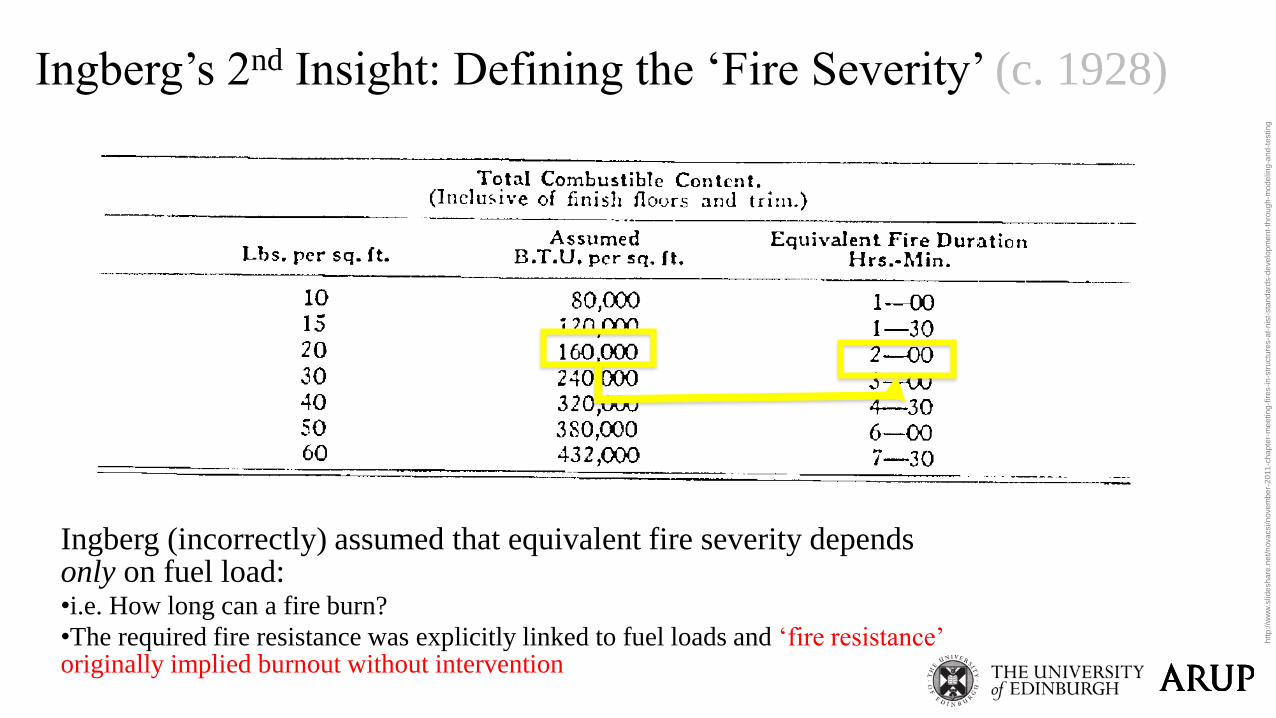
Ingberg’s 2nd Insight: Defining the ‘Fire Severity’ (c. 1928)
Ingberg (incorrectly) assumed that equivalent fire severity depends only on fuel load:•i.e. How long can a fire burn?
•The required fire resistance was explicitly linked to fuel loads and ‘fire resistance’ originally implied burnout without intervention
htt
p:/
/ww
w.s
lid
esh
are
.ne
t/n
ova
csi/n
ove
mb
er-
20
11
-ch
ap
ter-
me
etin
g-f
ire
s-i
n-s
tru
ctu
res-a
t-n
ist-
sta
nd
ard
s-d
eve
lop
me
nt-
thro
ug
h-m
od
elin
g-a
nd
-te
stin
g
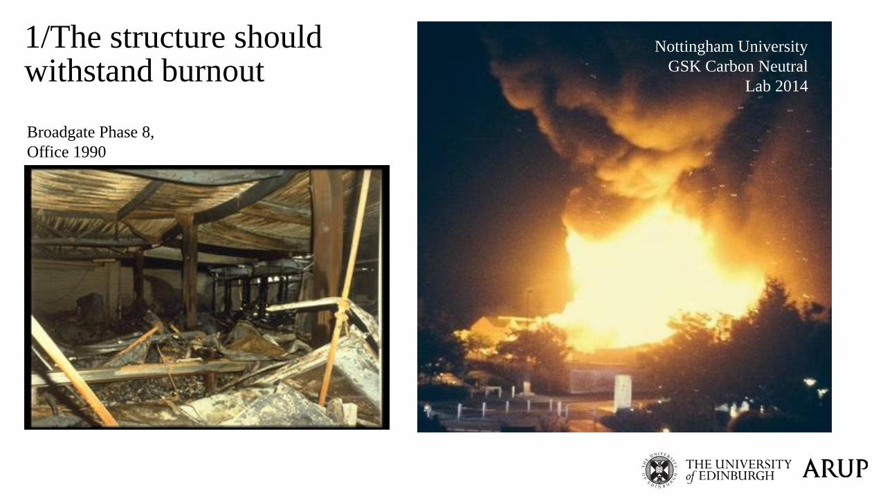
1/The structure should withstand burnout
Broadgate Phase 8,
Office 1990
Nottingham University
GSK Carbon Neutral
Lab 2014
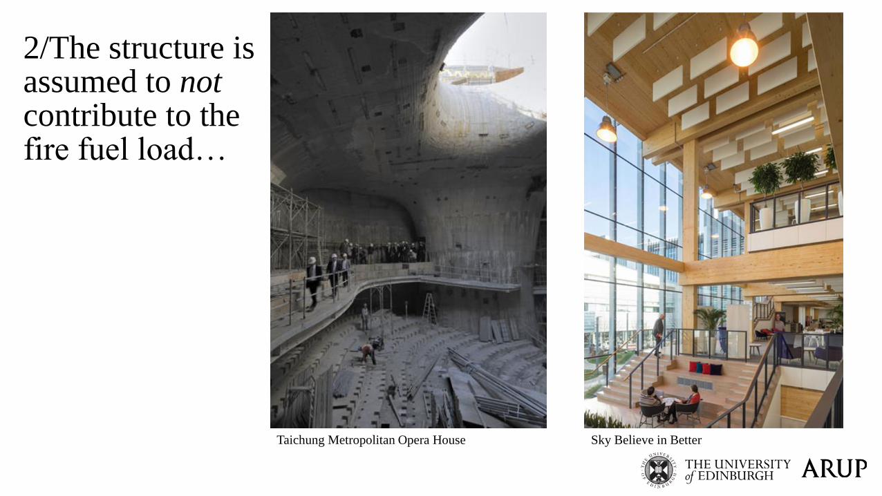
Taichung Metropolitan Opera House Sky Believe in Better
2/The structure is assumed to not contribute to the fire fuel load…

3/Conventional furnaces were not intended for timber …
Gas Temperature Gas Temperature
The test on concrete will use more fuel than tests on exposed timber to yield the same gas temperatures in a furnace:•Do timber buildings have less fuel in them than concrete buildings?
•Is this a ‘fair’ comparison of candidate structural framing systems?
Concrete Beam Timber Beam
Structural design for fire is different when ‘exposed’ mass timber is used
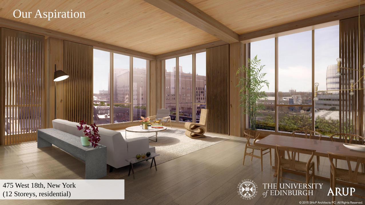
475 West 18th, New York
(12 Storeys, residential)
Our Aspiration
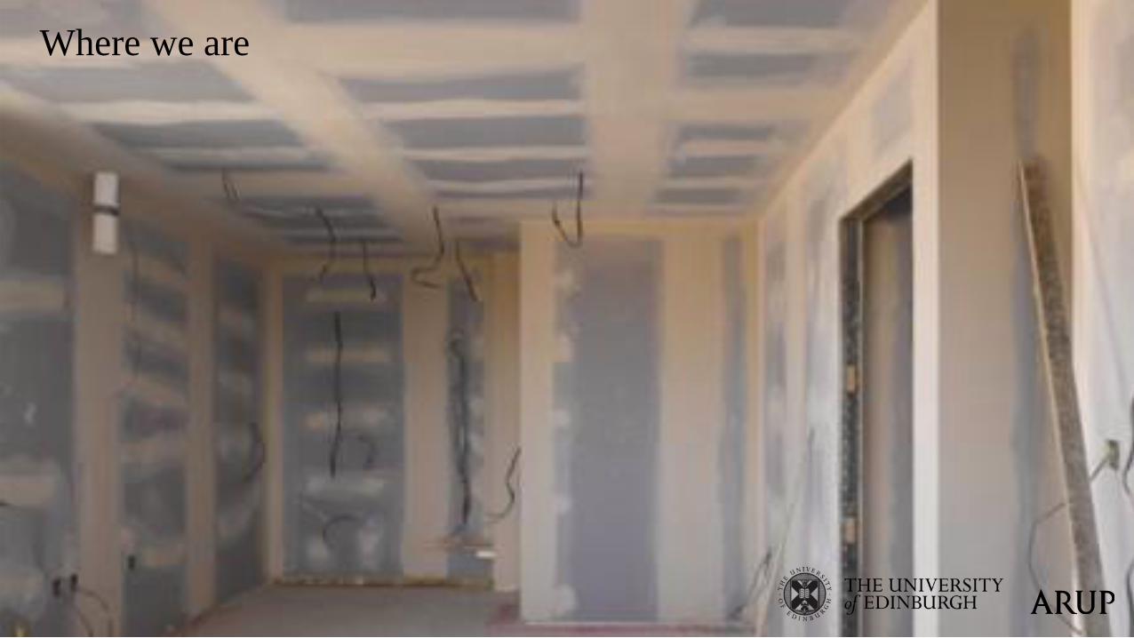
Where we are

Knowingly
The key to start truly pushing boundaries in tall and mass timber construction is to identify and address them as engineers…
The methodology for doing so is already well established for non-combustible construction

Total Fire Engineering Design:Non-Combustible Construction
Develop the design
fire(s)
Fire duration
Tem
per
atu
re
Established compartment fire models : (Cardington Natural Fire Safety
Concept 3)

Total Fire Engineering Design:Non-Combustible Construction
Develop the design
fire(s)
Fire Analysis: Thermal
Exposure
Incident Heat Flux / Cardington Natural Fire Safety Concept 3
Total Fire Engineering Design:Non-Combustible Construction
Develop the design
fire(s)
Fire Analysis: Thermal
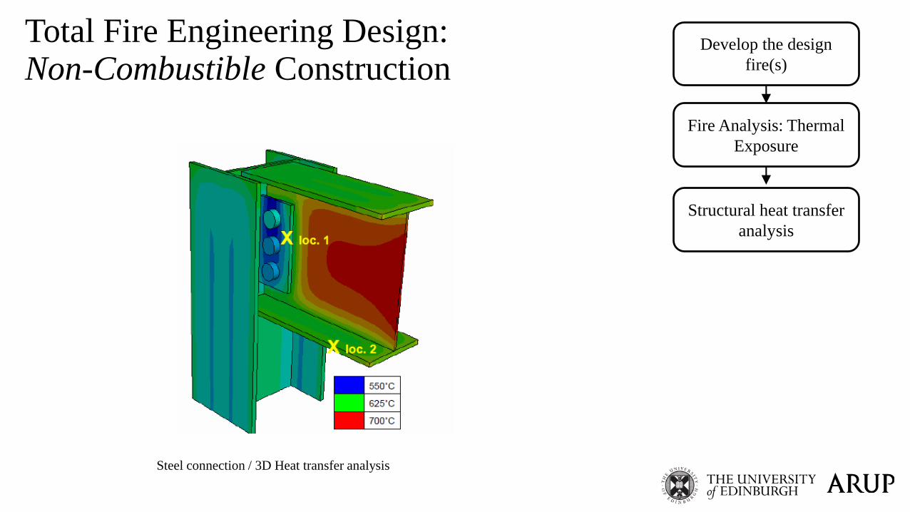
Exposure
Structural heat transfer
analysis
Steel connection / 3D Heat transfer analysis

Total Fire Engineering Design:Non-Combustible Construction
Develop the design
fire(s)
Fire Analysis: Thermal
Exposure
Structural heat transfer
analysis
Material response at
high temperatures
Concrete Spalling / Channel Tunnel ‘96

Total Fire Engineering Design:Non-Combustible Construction
Develop the design
fire(s)
Fire Analysis: Thermal
Exposure
Structural heat transfer
analysis
Material response at
high temperatures
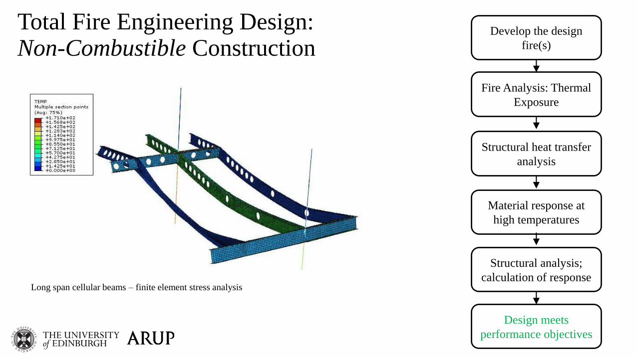
Structural analysis;
calculation of responseLong span cellular beams – finite element stress analysis
Total Fire Engineering Design:Non-Combustible Construction
Develop the design
fire(s)
Fire Analysis: Thermal
Exposure
Structural heat transfer
analysis
Material response at
high temperatures
Structural analysis;
calculation of response
Design meets
performance objectives
Long span cellular beams – finite element stress analysis

Total Fire Engineering Design:Non-Combustible Construction
Develop the design
fire(s)
Fire Analysis: Thermal
Exposure
Structural heat transfer
analysis
Material response at
high temperatures
Structural analysis;
calculation of response
Design meets
performance objectives
Design fails
performance objectives
Redesign
structure &
fire protection
Mitigate the
fire hazard
Fire duration
Tem
per
atu
re
Redesign of structure and/or
its fire protection
Mitigate the fire hazards

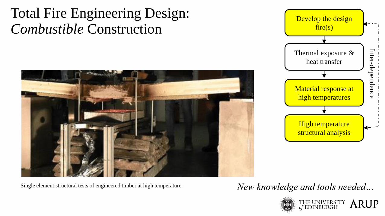
Total Fire Engineering Design:Combustible Construction
Develop the design
fire(s)
Arup – University of Edinburgh CLT Compartment fire tests, 2016
New knowledge and tools needed…

Total Fire Engineering Design:Combustible Construction
Develop the design
fire(s)
Thermal exposure &
heat transfer
Timber heat transfer model

Total Fire Engineering Design:Combustible Construction
Develop the design
fire(s)
Thermal exposure &
heat transfer
Material response at
high temperatures
Inter-d
epen
den
ce
Normal Wood
Pyrolysis zone
Char layer
Material tests of engineered timber under radiative heat flux
New knowledge and tools needed…
Total Fire Engineering Design:Combustible Construction
Develop the design
fire(s)
Thermal exposure &
heat transfer
Material response at
high temperatures
High temperature
structural analysis
Single element structural tests of engineered timber at high temperature
Inter-d
epen
den
ce
New knowledge and tools needed…

Total Fire Engineering Design:Combustible Construction
Develop the design
fire(s)
Thermal exposure &
heat transfer
Material response at
high temperatures
High temperature
structural analysis
Does the structure
survive burnout?
Inter-d
epen
den
ce
Extinction
Design needs to satisfy both stability and burnout performance criteria

Total Fire Engineering Design:Combustible Construction
Develop the design
fire(s)
Thermal exposure &
heat transfer
Material response at
high temperatures
High temperature
structural analysis
Does the structure
survive burnout?
Inter-d
epen
den
ceMitigate the
fire hazard
Design fails
performance
objectives
Redesign
structure &
fire protection
Design meets
performance objectivesRedesign the structure and/or its
fire protection
Mitigate the fire hazard
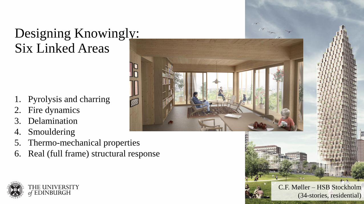
Designing Knowingly:Six Linked Areas
1. Pyrolysis and charring
2. Fire dynamics
3. Delamination
4. Smouldering
5. Thermo-mechanical properties
6. Real (full frame) structural response
C.F. Møller – HSB Stockholm
(34-stories, residential)

Knowledge Gap 2 – Fire Dynamics with Exposed Timber
Coupling between burning of fuel and burning of
the structure:•Faster fire growth & time to flashover
•No increase in gas temperatures (if ventilation controlled)
•Increased production of volatiles and smoke
•Increased severity of external flaming
•Increased total heat release rate
•Longer burning duration
•Potential for secondary flashover
•Does ‘fire resistance’ concept make sense?
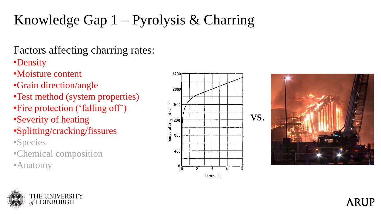
Knowledge Gap 1 – Pyrolysis & Charring
vs.
Factors affecting charring rates:•Density
•Moisture content
•Grain direction/angle
•Test method (system properties)
•Fire protection (‘falling off’)
•Severity of heating
•Splitting/cracking/fissures
•Species
•Chemical composition
•Anatomy
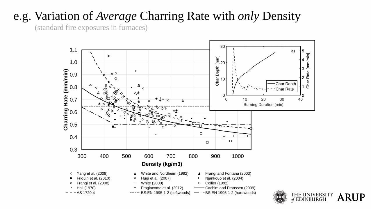
0.3
0.4
0.5
0.6
0.7
0.8
0.9
1.0
1.1
300 400 500 600 700 800 900 1000
Ch
arr
ing
Rate
(m
m/m
in)
Density (kg/m3)
Yang et al. (2009) White and Nordheim (1992) Frangi and Fontana (2003)
Friquin et al. (2010) Hugi et al. (2007) Njankouo et al. (2004)
Frangi et al. (2008) White (2000) Collier (1992)
Hall (1970) Fragiacomo et al. (2012) Cachim and Franssen (2009)
AS 1720.4 BS:EN 1995-1-2 (softwoods) BS EN 1995-1-2 (hardwoods)
e.g. Variation of Average Charring Rate with only Density(standard fire exposures in furnaces)

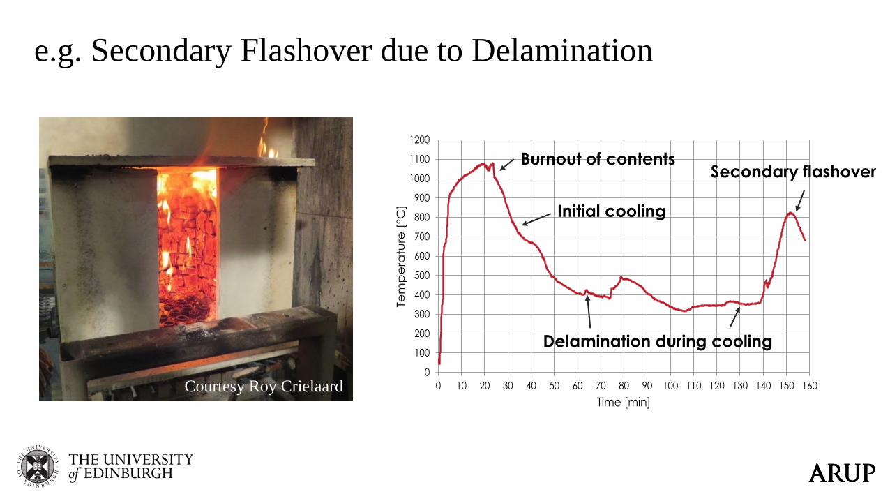
Knowledge Gap 3 – Delamination
Falling off or loss-of-stickability of charred
timber lamellae
• Effects on effective charring rates in furnace
tests can be accounted for
• Causes and contributory factors not understood:
• Adhesive type (MUF vs. PUR)?
• Critical temperatures?
• Orientation?
• Loading?
• Grain direction, species, moisture, lamella
thickness,
0
100
200
300
400
500
600
700
800
900
1000
1100
1200
0 10 20 30 40 50 60 70 80 90 100 110 120 130 140 150 160
Tem
pe
ratu
re [
°C]
Time [min]
Burnout of contents
Initial cooling
Delamination during cooling
Secondary flashover
e.g. Secondary Flashover due to Delamination
Courtesy Roy Crielaard
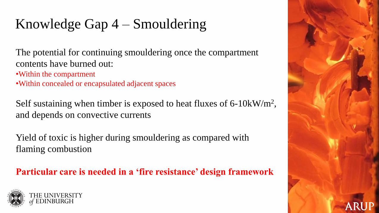
Knowledge Gap 4 – Smouldering
The potential for continuing smouldering once the compartment
contents have burned out:•Within the compartment
•Within concealed or encapsulated adjacent spaces
Self sustaining when timber is exposed to heat fluxes of 6-10kW/m2,
and depends on convective currents
Yield of toxic is higher during smouldering as compared with
flaming combustion
Particular care is needed in a ‘fire resistance’ design framework

0
20
40
60
80
100
0 50 100 150 200 250 300
Rel
ati
ve
Yo
un
g's
Mo
du
lus
(%)
Temperature (°C)
Konig and Walleij [55] Ostman [60]
Thomas [57] Sulzberger [64]
Nyman [69] Lie [58]
Kollman [63] Preusser [70]
Young [66] Janssens [68]
James [71] Schaffer [52]
Knowledge Gap 5 – Thermo-mechanical Properties
0
20
40
60
80
100
0 50 100 150 200 250 300
Rel
ati
ve
Ten
sile
Str
eng
th (
%)
Temperature (°C)
Konig and Walleij [55] Knudson & Schneiwind [56]
Thomas [57] Schaffer [52]
Lie [58] Lau & Barrett [59]
Ostman [60] Schaffer [61]
Kollmann [62]
0
20
40
60
80
100
0 50 100 150 200 250 300
Rel
ati
ve
Co
mp
ress
iveS
tren
gth
(%
)
Temperature (°C)
Konig & Walleij [55] Knudson & Schneiwind [56]
Thomas [57] Schaffer [52]
Kollmann [63] Sulzberger [64]
Youngs [65] Young [66]
Ingberg [67]
Tensile Strength Compressive Strength Elastic Modulus

Knowledge Gap 6 – Structural Response(as distinct from single element response)
Mass timber elements are widely considered to perform well in fire but…
There are uncertainties:•Full frame structural response (is a dominant factor for steel buildings but widely ignored for timber)
•Both full frame and element level failure modes (e.g. rolling shear)
•Compression elements and stability failures
•Connection response and failure modes
Pedro Palma, Andrea Frangi, Erich Hugi, Paulo Cachim and Helena Cruz
A.1 (10 mm gap) A.2 (20 mm gap) A.3 (0 mm gap)
Figure 7. Influence of the gap between the beam and the column: connections A.1, A.2, and A.3 after the fire tests.
The common commercially available concealed beam-hanger (A.5) had gap of only 6 mm between
the beam and the column (Figure 2.1 and Table 2), but a much lower estimated load-carrying capacity of
the column-side of the connection (Table 3 and Figure 4a), although it failed on the beam-side at normal
temperature. This commercial connection exhibit a fire resistance 5 minutes lower than the custom A.1
connection and failed in the column-side, with a failure mode similar to that of the connections A.2.
However, the load in connection A.5 during the fire test was about 40% of the load-carrying capacity of
the beam-side at normal temperature, instead of the 30% in connections A.1-3.
A.4 (reinforced) A.5 (commercial beam-hanger)
Figure 8. Connections A.4 and A.5 after the fire tests.
The influence of the failure mode can be analysed in the connections B.1 and B.2. These connections
had smaller sized dowels (diameter of 8 mm) and showed brittle splitting (B.1) and ductile
embedment/dowel failures (B.2) at normal temperature. In the fire tests, however, both typologies
exhibited similar extensive embedment failures, followed by splitting. In fire, the smaller minimum dowel
spacing perpendicular to the grain prescribed by EN 1995-1-1 (only 3·d, compared to 5·d parallel to the
grain) leads to a premature failure when all the wood between the dowels is charred (Figure 9). Also the
smaller minimum unloaded edge distances (connection B.2) perpendicular to the grain (only 3·d, compared to 7·d parallel to the grain) result in the complete charring of the wood surrounding the
outermost dowels. Regardless of the failure mode at normal temperature, both connection typologies
exhibited approximately the same fire resistance.
B.1 B.2
Figure 9. Connections B.1 and B.2 after the fire tests.
Pedro Palma, Andrea Frangi, Erich Hugi, Paulo Cachim and Helena Cruz
Connections C.1 exhibited shear/splitting failures at normal temperature and the highest load-carrying
capacities of the R30 connections (Table 3). In the fire tests, they reached approximately the same fire
resistance as connections A.1. In fire, the dowels remained mostly straight and the wood surrounding the
dowels closer to the unloaded edge charred completely. After failure, splitting cracks could be observed
in the beam side.
C.1
Figure 10. Connections C.1 after the fire tests.
Connections A.6 and C.2 reached more than the estimated minimum 60 minutes of fire resistance [8].
Regarding connections A.6 (with 12 mm dowels), the long fire exposure charred the wood below and
above the header steel plate nailed to the column, affecting the tension (nail withdrawal) and compression
zones and allowing the steel plates to rotate (Figure 11, left). The dowels’ end distance in connections C.1
(8 mm dowels) was smaller than in connections A.6 and, consequently, so was the moment in the header
plate. Therefore, the rotation of the header plate was negligible. On the other hand, the charred depth in
the zone between the dowels and the end of the beam was significantly higher than elsewhere in the
beam, due to additional heat coming from the burning column-member and transferred by the dowels into
the cross-section. After the wood between the dowels charred, the load was mostly transferred through the
last dowel and it ultimately bent (Figure 11, right).
A.6 C.2
Figure 11. Connections A.6 and C.2 after the fire tests.
Finally, the commercial aluminium dovetail connection D.1 also reached more than 30 minutes of fire
resistance, failing in the connector itself after 36 minutes. This connection had a gap of 18 mm between
the beam and the column (thickness of the connector), which is larger than the 10 mm of most of the other
connections.
D.1
Figure 12. Connection D.1 after the fire test.
From Palma et al. (2014)

“we cling to the myth that timber
construction presents risks, while concrete
and steel do not. Nonsense. Every material
presents risks, but we manage them in
different ways”
Russell Fortmeyer, Arup, 2011
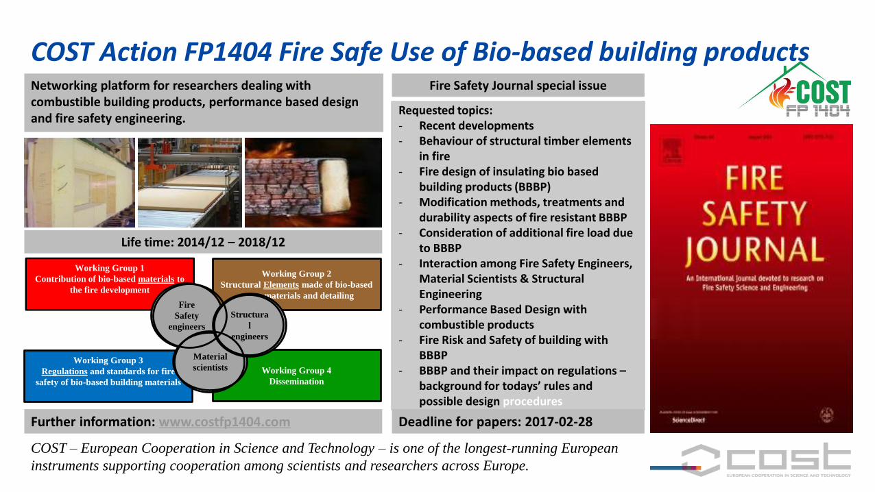
Requested topics: - Recent developments- Behaviour of structural timber elements
in fire- Fire design of insulating bio based
building products (BBBP)- Modification methods, treatments and
durability aspects of fire resistant BBBP- Consideration of additional fire load due
to BBBP- Interaction among Fire Safety Engineers,
Material Scientists & Structural Engineering
- Performance Based Design with combustible products
- Fire Risk and Safety of building with BBBP
- BBBP and their impact on regulations –background for todays’ rules and possible design procedures
Fire Safety Journal special issue
Deadline for papers: 2017-02-28
Life time: 2014/12 – 2018/12
Networking platform for researchers dealing with combustible building products, performance based design and fire safety engineering.
Further information: www.costfp1404.com
COST – European Cooperation in Science and Technology – is one of the longest-running European
instruments supporting cooperation among scientists and researchers across Europe.
Working Group 1
Contribution of bio-based materials to
the fire development
Working Group 2
Structural Elements made of bio-based
materials and detailing
Working Group 3
Regulations and standards for fire
safety of bio-based building materials
Working Group 4
Dissemination
Fire
Safety
engineers
Material
scientists
Structura
l
engineers
COST Action FP1404 Fire Safe Use of Bio-based building products