
Fire Engineering in Practice – State of the Art in...
128
Buro Happold the engineering of excellence Fire Engineering in Practice – State of the Art in Performance-based Design Florian Block COST-TU0904 – Training School
Transcript of Fire Engineering in Practice – State of the Art in...

Buro Happold the engineering of excellence
Fire Engineering in Practice – State of the Art in Performance-based DesignFlorian BlockCOST-TU0904 – Training School

Buro Happold the engineering of excellence
Agenda
• What is it a fire engineer does?• What is Performance Based Design?• How is Performance Based Design done in reality?• Project examples• Conclusions
Tento obrázek nyní nelze zobrazit.

Buro Happold the engineering of excellence
Buro HappoldFounded 1976 in Bath by Sir Ted Happold and 6 partners26 Offices around the world~1500 members of staff
• Structural Engineering• Building Services• Facades• Infrastructure• Sustainability• Geotechnics• Lighting• Etc…..• And Fire Engineering

Buro Happold the engineering of excellence
Buro Happold Office LocationsBuro Happold FEDRA Office

Buro Happold the engineering of excellence
Fire Engineering

Circle of Fire Engineering

Fire Safety Objectives
• Life‐safety • Property protection –Museums, galleries• Business continuity – Finance institutes, data centres, manufacturing facilities• Security Requirements ‐Prisons• Educational continuity ‐Schools• Operational requirements –Hospitals (surgical theatres)• Specific local requirements –Local AHJ

Focus/Feasibility
• Emergency vehicle access around site & to buildings
• Fire protection infrastructure•Building separation distances•Required protection of facades
•Building access requirements
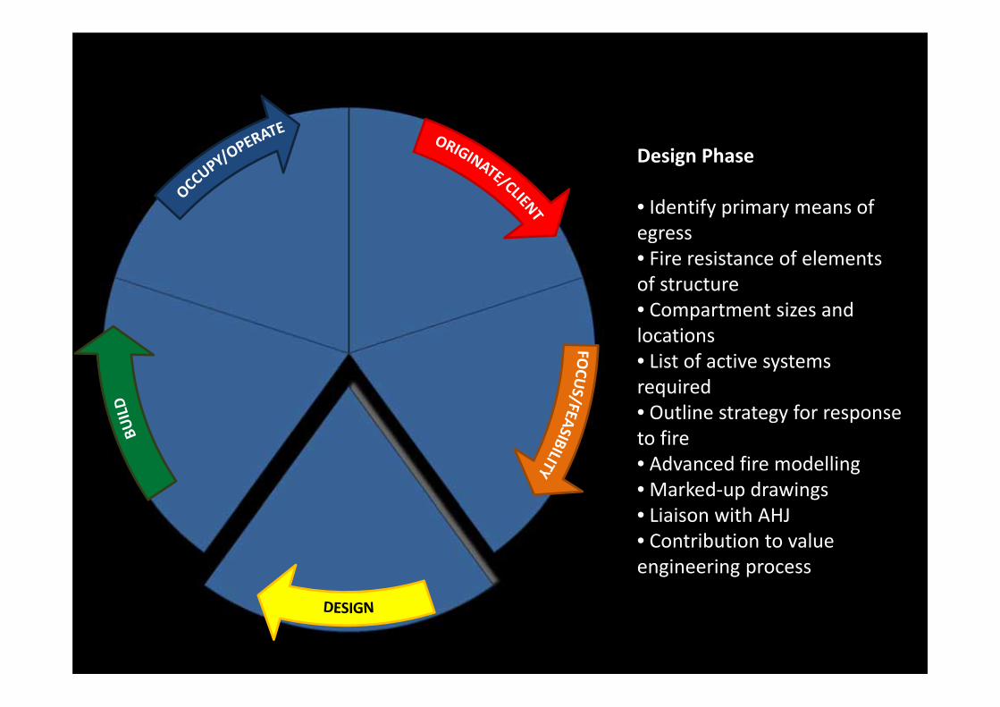
Design Phase
• Identify primary means of egress • Fire resistance of elements of structure• Compartment sizes and locations• List of active systems required• Outline strategy for response to fire• Advanced fire modelling• Marked‐up drawings• Liaison with AHJ• Contribution to value engineering process

Build/Construction Phase
• Site Inspections•Checks for compliance with fire strategy
•Attendance at commissioning of fire systems – particularly for fire engineering solutions
•As‐built Fire Strategy• Trouble‐shooting

Occupy/Operate
•Periodic Audit•Portfolio Management• Fire safety training•Phase Occupancy Strategy•Personal Emergency Evacuation Plans ‐ schools
•Operations and Maintenance Manuals – testing of fire engineered designs
• Training ‐ How does this fire engineered solution work in practice?

‘Connection’ to Fire Engineer
Fire Engineer
Structures
Architecture
Electrical
Mechanical
Plumbing
Landscape
Facades

Buro Happold the engineering of excellence
Performance Based Design
Tailored solutions to solve fire safety issues for which prescriptive solutions don’t give satisfying results in the areas of:
• Life safety• Robustness of Structures• Architectural Vision• Sustainability• Cost

Buro Happold the engineering of excellence
Performance Based Design
Approach
PerformanceBased
CodeCompliant
TimeApprovals Risk Safety
Calculable S
afety
Value
Return on investm
ent

Buro Happold the engineering of excellence
Performance Based Design
x x
x
x xxx
x x x
Engineering
Code
80%
100%
Safety
Cost

Buro Happold the engineering of excellence
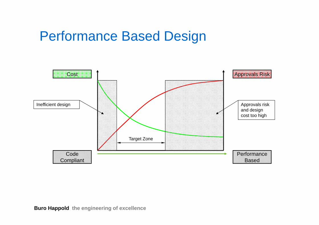
Approvals Risk
Performance Based Design
CodeCompliant
PerformanceBased
Cost

Buro Happold the engineering of excellence
Approvals Risk
Performance Based Design
CodeCompliant
PerformanceBased
Cost
Inefficient design

Buro Happold the engineering of excellence
Approvals Risk
Performance Based Design
CodeCompliant
PerformanceBased
Cost
Inefficient design Approvals risk and design cost too high
Buro Happold the engineering of excellence
Approvals Risk
Performance Based Design
CodeCompliant
PerformanceBased
Cost
Inefficient design Approvals risk and design cost too high
Target Zone

Buro Happold the engineering of excellence
Performance Based Design - Process
1. Conduct cost benefit analysisScoping studyTest the market
2. Initial consultationConsult stakeholder (Client, insurers, approving authority and fire brigade)Agree acceptance criteriaAgree design fires scenarios
3. Conduct AnalysisSmoke and fire behaviourPeople movement Structural response

Buro Happold the engineering of excellence
Performance Based Design - Process
4. Prepare a detailed report
5. Gain building control approval
6. Construction drawings
7. Site inspection

Buro Happold the engineering of excellence
Fire Safety Objectives
Life Safety of people in the building
Protection of other property
Facilitate fire fighting
Property Protection– Buildings– Contents
Business / Operational Continuity
Protection of Brand / Image

Buro Happold the engineering of excellence
Acceptance criteria
For structure:• Stability of structure• Containment of fire
For escape:• Visibility• Toxicity• Temperature• Air velocity and pressures
For fire fighting:• Access• Fire fighting systems

Determining the Design Fire ScenariosPerform a Qualitative Risk and Hazard assessment
• Find a number of worst case design fire scenarios
• Also consider low possibility but high consequence event

Determine the Design Fire
Isolated Fires• Develop in large open
spaces or outside• Fuel controlled
Compartment Fires• Heat is conserved by
surrounding structure• Much higher temperatures
than isolated fires• Ventilation controlled

Agree with Stakeholders - Fire Engineering Brief (FEB)
Why?
• Performance based designs introduce risk
• Way to consult stakeholders early• Aims to establish platform of principles for
fire engineering to work from

Buro Happold the engineering of excellence
Time as Means of MeasurementTemperature
Time
Localevacuationperiod
Time to untenability incompartment of origin
Marginof safety
Time to untenability of escape routes
Global evacuation period Marginof safety
The position of this linemoves in accordance withthe risk
Time to global/progressive collapse or unacceptable collateral damage.This will vary in accordance with the acceptance of society.
Actual evacuation time
Time as Measure – ASET vs RSET
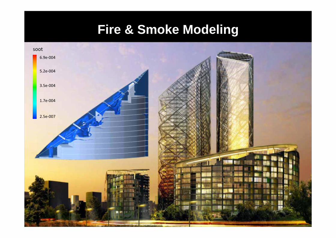
Fire & Smoke Modelingsoot
6.9e‐004
5.2e‐004
3.5e‐004
1.7e‐004
2.5e‐007

Fire & Smoke ModelingHand Calculations
Axisymmetric Plume
21
25
max
35
31
1
52
452
60
460144
0042.0)022.0(,_
533.0
O
OS
P
CSOS
cc
cl
TTTdV
mV
TRPmC
QKTT
QzQmzzwhen
Qz
Axisymmetric Plume

Fire & Smoke ModelingHand Calculations
Balcony Spill Plume
21
25
max
21
35
31
21
157
51
31
31
2
452
60
460144
18.0)()(077.0
)15098.0(31.0
)25.0()(12.0
O
OS
P
CSOS
wwwww
bb
b
TTTdV
mV
TRPmC
QKTT
HAazHAm
WzWQm
HzQWm
Balcony Spill Plume

Fire & Smoke ModelingHand Calculations
Where the principle is to maintain a stable smoke layer in a regular ‘geometry’ hand calcs will often do
Defined Clear Layer Height

Fire & Smoke ModelingComputational Fluid Dynamics (CFD)

Fire & Smoke ModelingComputational Fluid Dynamics (CFD)
Define……..
Geometry
X m
Y m
Z m

Fire & Smoke ModelingComputational Fluid Dynamics (CFD)
Define……..
Geometry
Boundary Materials

Fire & Smoke ModelingComputational Fluid Dynamics (CFD)
Define……..
Geometry
Boundary materials
Mesh

Fire & Smoke ModelingComputational Fluid Dynamics (CFD)
Define……..
Geometry
Boundary materials
Mesh
Fire Location/size

Fire & Smoke ModelingComputational Fluid Dynamics (CFD)
Define……..
Geometry
Boundary materials
Mesh
Fire Location/size
Soot Yield

Fire & Smoke ModelingComputational Fluid Dynamics (CFD)
Define……..
Geometry
Boundary materials
Mesh
Fire Location/size
Soot Yield
Extract Provisions

Fire & Smoke ModelingComputational Fluid Dynamics (CFD)
Define……..
Geometry
Boundary materials
Mesh
Fire Location/size
Soot Yield
Extract Provisions
Replacement Air

Fire & Smoke ModelingComputational Fluid Dynamics (CFD)
Define……..
Geometry
Boundary materials
Mesh
Fire Location/size
Soot Yield
Extract Provisions
Replacement Air
External Temp

Fire & Smoke ModelingComputational Fluid Dynamics (CFD)
Define……..
Geometry
Boundary materials
Mesh
Fire Location/size
Soot Yield
Extract Provisions
Replacement Air
External Temp
Wind Conditions

Fire & Smoke ModelingComputational Fluid Dynamics (CFD)

CFD Assessment – Example of a Shopping Mall

CFD Assessment – Results for ‘West’ Case – Video
• Video 1 – Smoke Production Longitudinal Section of Mall
• Video 2 – Smoke Visibility Longitudinal Section of Mall
• Video 3 – Smoke Visibility Cross Section at Fire Location

Egress Modeling

Egress Modelling
There are different approaches to egress modelling:• Follow prescriptive escape width and distance provisions in codes• Use simple flow calculations by hand• Use network models (Steps,…)• Use agent based egress modelling (Exodus,…)

Define & Populate Geometry

Determine Population Characteristics
• Age/Gender
• Staff/Public
• Mobility (disabled occupant)
• Walking speed
• Distance to exit
• Flow rate though doors
• Flow rates down/up stairs
• Decision making algorithms;
- Pre movement time- Nearest exit- Main exit- Follow crowd- Redistribution upon queuing

Fill Geometry

Define Fire Location

Egress Modeling Time to Evacuate + Factor of Safety < Time to untenable Conditions

Structural Fire Engineering Design Methods

Heat transfer from fire to structure - compartment fire1. Table 9 and 10 in BS5950-8: Temperature depending on flange thickness.
2. Simple heat transfer method in Eurocode 3-1.2 for protected and unprotected steel members depending on section factor.
3. Finite element software: SAFIR, TASEF, ANSYS, ABAQUS
0
100
200
300
400
500
600
700
800
900
1000
0 20 40 60 80 100 120
Time (mins)
Tem
pera
ture
(°C
)
476 FireUnproteced Beam60-minute beam60-minute column620 C̊540 C̊

Heat transfer from fire to structure – localised fire
RadiationConvection if member is in the plumeView factor calculations for radiation!

Structural Responds – Fire limit state
A fire limit state should be treated as an Accidental Limit Statewith its own associated partial factors
Load Factors (f) - Table 2 BS5950-8• Dead Loads 1.0• Imposed Loads (permanent) 1.0• Imposed Loads (non-permanent) 0.8
for commercial offices 0.5• Wind Loads 0.33

Steel stress-strain curves at high temperatures
Strength/stiffness reduction factors for elastic modulus and yield strength (2% strain).
Strain (%)0.5 1.0 1.5 2.0
Stress (N/mm2)
0
300
250
200
150
100
50
20°C
200°C300°C
400°C500°C
600°C
700°C
800°C
Elastic modulus at 600°C reduced by about 70%.
Yield strength at 600°C reduced by over 50%.

1.00.90.80.70.60.50.40.30.20.10
1 2 3 4
1000°C800°C
20°C
200°C
400°C
600°C
Strain (%)
Normalised stress
Concrete also loses strength and stiffness from 100°C upwards.
Does not regain strength on cooling.
High temperature properties depend mainly on aggregate type used.
Concrete stress-strain curves at high temperatures

Limiting Temperature > Design Temperature
Limiting Temperature Method
The Design temperature is the temperature which the section will reach at the prescribed fire resistance time. It is based on member type and fire resistance
The Limiting temperature is the temperature at which the section is deemed to fail. It is based on member type, thermal gradient and Load Ratio
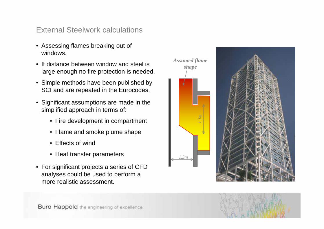
External Steelwork calculations
1.5m
Assumed flameshape
• Assessing flames breaking out of windows.
• If distance between window and steel is large enough no fire protection is needed.
• Simple methods have been published by SCI and are repeated in the Eurocodes.
• Significant assumptions are made in the simplified approach in terms of:
• Fire development in compartment
• Flame and smoke plume shape
• Effects of wind
• Heat transfer parameters
• For significant projects a series of CFD analyses could be used to perform a more realistic assessment.
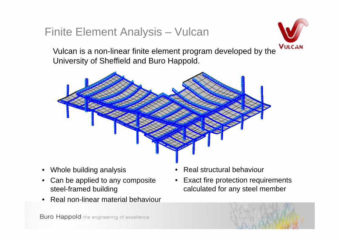
Finite Element Analysis – Vulcan
• Whole building analysis• Can be applied to any composite
steel-framed building• Real non-linear material behaviour
• Real structural behaviour• Exact fire protection requirements
calculated for any steel member
Vulcan is a non-linear finite element program developed by the University of Sheffield and Buro Happold.

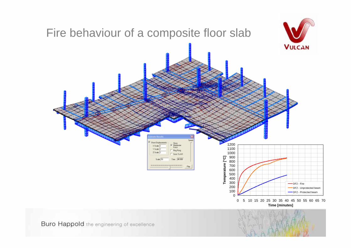
Fire behaviour of a composite floor slab
0100200300400500600700800900
100011001200
0 5 10 15 20 25 30 35 40 45 50 55 60 65 70Time [minutes]
Tem
pera
ture
[°C
]
DF2 - Fire
DF2 - Unprotected beam
DF2 - Protected beam

Fire behaviour of a composite floor slab
0100200300400500600700800900
100011001200
0 5 10 15 20 25 30 35 40 45 50 55 60 65 70Time [minutes]
Tem
pera
ture
[°C
]
DF2 - Fire
DF2 - Unprotected beam
DF2 - Protected beam

Fire behaviour of a composite floor slab
0100200300400500600700800900
100011001200
0 5 10 15 20 25 30 35 40 45 50 55 60 65 70Time [minutes]
Tem
pera
ture
[°C
]
DF2 - Fire
DF2 - Unprotected beam
DF2 - Protected beam

Fire behaviour of a composite floor slab
0100200300400500600700800900
100011001200
0 5 10 15 20 25 30 35 40 45 50 55 60 65 70Time [minutes]
Tem
pera
ture
[°C
]
DF2 - Fire
DF2 - Unprotected beam
DF2 - Protected beam

Fire behaviour of a composite floor slab
0100200300400500600700800900
100011001200
0 5 10 15 20 25 30 35 40 45 50 55 60 65 70Time [minutes]
Tem
pera
ture
[°C
]
DF2 - Fire
DF2 - Unprotected beam
DF2 - Protected beam

Fire behaviour of a composite floor slab
0100200300400500600700800900
100011001200
0 5 10 15 20 25 30 35 40 45 50 55 60 65 70Time [minutes]
Tem
pera
ture
[°C
]
DF2 - Fire
DF2 - Unprotected beam
DF2 - Protected beam

Fire behaviour of a composite floor slab
0100200300400500600700800900
100011001200
0 5 10 15 20 25 30 35 40 45 50 55 60 65 70Time [minutes]
Tem
pera
ture
[°C
]
DF2 - Fire
DF2 - Unprotected beam
DF2 - Protected beam

Fire behaviour of a composite floor slab
0100200300400500600700800900
100011001200
0 5 10 15 20 25 30 35 40 45 50 55 60 65 70Time [minutes]
Tem
pera
ture
[°C
]
DF2 - Fire
DF2 - Unprotected beam
DF2 - Protected beam

Fire behaviour of a composite floor slab
0100200300400500600700800900
100011001200
0 5 10 15 20 25 30 35 40 45 50 55 60 65 70Time [minutes]
Tem
pera
ture
[°C
]
DF2 - Fire
DF2 - Unprotected beam
DF2 - Protected beam
Fire behaviour of a composite floor slab
0100200300400500600700800900
100011001200
0 5 10 15 20 25 30 35 40 45 50 55 60 65 70Time [minutes]
Tem
pera
ture
[°C
]
DF2 - Fire
DF2 - Unprotected beam
DF2 - Protected beam

Fire behaviour of a composite floor slab
0100200300400500600700800900
100011001200
0 5 10 15 20 25 30 35 40 45 50 55 60 65 70Time [minutes]
Tem
pera
ture
[°C
]
DF2 - Fire
DF2 - Unprotected beam
DF2 - Protected beam

Fire behaviour of a composite floor slab
0100200300400500600700800900
100011001200
0 5 10 15 20 25 30 35 40 45 50 55 60 65 70Time [minutes]
Tem
pera
ture
[°C
]
DF2 - Fire
DF2 - Unprotected beam
DF2 - Protected beam

Fire behaviour of a composite floor slab
0100200300400500600700800900
100011001200
0 5 10 15 20 25 30 35 40 45 50 55 60 65 70Time [minutes]
Tem
pera
ture
[°C
]
DF2 - Fire
DF2 - Unprotected beam
DF2 - Protected beam

Fire behaviour of a composite floor slab
0100200300400500600700800900
100011001200
0 5 10 15 20 25 30 35 40 45 50 55 60 65 70Time [minutes]
Tem
pera
ture
[°C
]
DF2 - Fire
DF2 - Unprotected beam
DF2 - Protected beam

Fire behaviour of a composite floor slab
0100200300400500600700800900
100011001200
0 5 10 15 20 25 30 35 40 45 50 55 60 65 70Time [minutes]
Tem
pera
ture
[°C
]
DF2 - Fire
DF2 - Unprotected beam
DF2 - Protected beam

Fire behaviour of a composite floor slab
0100200300400500600700800900
100011001200
0 5 10 15 20 25 30 35 40 45 50 55 60 65 70Time [minutes]
Tem
pera
ture
[°C
]
DF2 - Fire
DF2 - Unprotected beam
DF2 - Protected beam

Results
Start of FireDetection
Local evacuation completes
Flashover
Global evacuation completes
Firefighters intervention
Stability of structure fails
Termination of heating phase for this fire scenario
75 minutes - factor of safety against scenario if heating continues*Automatic
sprinklers operate
Beam deflections subject to standard fire heating
Real fire subject to sprinklers operation
Real fire with high ventilation
Standard fire curve
-1600
-1400
-1200
-1000
-800
-600
-400
-200
0-30 0 30 60 90 120 150
Dis
plac
emen
t (m
m)
0
200
400
600
800
1000
1200
1400
Time (mins)
Tem
pera
ture
(°C
)
Primary BeamDisplacement
IntermediateBeamDisplacement
Standard FireCurve
Real Fire Curve

Sensitivity Study
• It is essential that sufficient sensitivity studies are performed to ensure that a robust solution.
• The input parameter and boundary conditions need to be varied beyond the normal design assumptions.
• Check for sudden changes in behaviours - ‘Cliff edge analysis’

Reporting and Quality control of Assessment
Reporting:• Detailed documentation of all assumptions and input variable with
appropriate references• Full results in calculations reports• Summary report for stakeholders
Checking:• 4 eyes concept• Design reviews and sanity checks by senior staff• Third party checking

Site Inspections and performance tests
• Site inspections are essential for performance based solutions during construction and after completion.
• Testing of mechanical systems – smoke test• Trial evacuations

Buro Happold the engineering of excellence
Modelling Process
IFE – Special Interest Group• Fire Modelling
Currently draft
Comment welcome
Size, growth and location Advisory Box 1 - NAB to collate
Heat release A list of recognised design fires
Fuel type and amount and references for test data.
Ventilation conditions
Client
Contractor
Design Team
Fire Service
Insurers
Legislation
Owner / occupier
Regulatory Enforcers
Sub-contractors
Advisory Box 2:
AJ - structural modelling
DB - smoke modelling
JB - evacuation modellingGW - heat transfer modelling
END
OR
Prescriptive solution, or
OR Scenario enveloped by another scenario
Cost / time relative to project
Qualifications of user
Training needs
Design review
Calcualtion checks
Deliverables
Deadlines
OUTPUT
For each fire scenario:
- remove the risk, or
- define the methodology for assessment
and the PQP and gain approval.
Advisory Box 3:
AJ - structural modelling
DB - smoke modelling
JB - evacuation modelling
GW - heat transfer modelling
Are the initial geometry, conditions and boundary conditions accurately represented? Advisory Box 4:
AJ - structural modelling
DB - smoke modelling
Convergence JB - evacuation modelling
Result integrity GW - heat transfer modelling
Advisory Box 5:
AJ - structural modelling
OUTPUT DB - smoke modelling
Build a model for simulation JB - evacuation modelling
Check the model set-up GW - heat transfer modelling
Run the simulations
Check the results
There are several documents that provide structures for reporting, such as:
BS 7974: 2001 - Section 5
OUTPUT NFPA 101 - Chapter 5
Review the technical quality International Fire Engineering Guidance
Document and report the process
Rejoin loop as appropriate.
Are results commensurate with expectations
Check inputs have been reproduced
Is model valid for solutions produced
Sanity check
Individual SimulationsTECHNICAL
Technical Quality Review
Can
be
hand
cal
cula
tions
, com
plex
mod
els,
etc
.
Rep
eat u
ntil
enou
gh s
imul
atio
ns to
test
sen
sitiv
ity
to d
iffer
ent f
ire s
cena
rios
and
mod
el u
ncer
tain
ty
(phy
sica
l, nu
mer
ical
, des
ign,
regu
lato
ry, e
tc.)
QUALITY REVIEW
REPORT
Groups of simulations for consistency
Review against expectationReview against original objectives
Review against acceptance criteria
If OK
Hand
Impirical
Numerical
Select Tool
Verification and Validation
LimitationsDeterministic
Risk Based
Select Method
and
Define Means of Measurement
Test / experimental
Analytical
Quantitative
Fire Safety Strategy,
Absolute
Relative
Assessment
Assessment
Remove Risk
Assess Risk Qualitative
Acceptance Criteriaand Safety Margin
SOLUTION STRATEGY
(and expectations)
Consider solutionsDefine outputs and acceptance criteria
Important physical processesMost cost effective method
Data requirements
Idealisation
or Scope of Work
(IFEG)
Agree Objectives Stakeholders
Abstract Description Important physical conditions
Environment
Physical Hazard
Fire Engineering Brief
(BS 7974 QDR)
Consequence of occurance Life-safety
Property protection
Business continutity
Toxicity
Radiaion
Risk of Hazard Likelihood of occurance
Fire Charateristics
Smoke
NEEDS ASSESSMENT
SPECIFICATION
(Scenario Identification)
SIMULATE
POST-PROCESS
PRE-PROCESS
OUTPUT:
Outline the problem
If not OK Critical review of predicted
physical behaviour.
Project Instruction Define Scenarios to be Modelled
Identify
Collect
Review
Analyse
Rep
eat u
ntil
valid
and
alig
ned
Computational Domain
Geometry Definition
Meshing (spatial and numerical discretisation)
Initial Conditions (including loads)
Geometrical and material properties
Project Quality Plan
Data Collection
Approval to proceed
Model integrity tests
Solution solver settings
Convergence Criteria
Boundary Conditions
Physical and behavioural submodels
Output requirements
Simulation time and temporal discretisation

Buro Happold the engineering of excellence
Problem Specification (Scenario Setting)
Size, growth and location Advisory Box 1 - NAB to collate
Heat release A list of recognised design fires
Fuel type and amount and references for test data.
Ventilation conditions
Client
Contractor
Design Team
Fire Service
Insurers
Legislation
Owner / occupier
Regulatory Enforcers
Sub-contractors
Advisory Box 2:
AJ - structural modelling
DB - smoke modelling
JB - evacuation modelling
GW - heat transfer modellingAcceptance Criteriaand Safety Margin
Consider solutionsDefine outputs and acceptance criteria
Important physical processesMost cost effective method
Data requirements
Idealisation
or Scope of Work
(IFEG)
Agree Objectives Stakeholders
Abstract Description Important physical conditions
Environment
Physical Hazard
Fire Engineering Brief
(BS 7974 QDR)
Consequence of occurance Life-safety
Property protection
Business continutity
Toxicity
Radiaion
Risk of Hazard Likelihood of occurance
Fire Charateristics
Smoke
NEEDS ASSESSMENT
SPECIFICATION
(Scenario Identification)
OUTPUT:
Outline the problem

Buro Happold the engineering of excellence
Solution StrategyEND
OR
Prescriptive solution, or
OR Scenario enveloped by another scenario
Cost / time relative to project
Qualifications of user
Training needs
Design review
Calcualtion checks
Deliverables
Deadlines
OUTPUT
For each fire scenario:
- remove the risk, or
- define the methodology for assessment
and the PQP and gain approval.
Hand
Impirical
Numerical
Select Tool
Verification and Validation
LimitationsDeterministic
Risk Based
Select Method
and
Define Means of Measurement
Test / experimental
Analytical
Quantitative
Fire Safety Strategy,
Absolute
Relative
Assessment
Assessment
Remove Risk
Assess Risk Qualitative
SOLUTION STRATEGY
(and expectations)
Project Instruction Define Scenarios to be Modelled
Identify
Collect
Review
Project Quality Plan
Data Collection
Approval to proceed

Buro Happold the engineering of excellence
AnalyseAdvisory Box 3:
AJ - structural modelling
DB - smoke modelling
JB - evacuation modelling
GW - heat transfer modelling
Are the initial geometry, conditions and boundary conditions accurately represented? Advisory Box 4:
AJ - structural modelling
DB - smoke modelling
Convergence JB - evacuation modelling
Result integrity GW - heat transfer modelling
Advisory Box 5:
AJ - structural modelling
OUTPUT DB - smoke modelling
Build a model for simulation JB - evacuation modelling
Check the model set-up GW - heat transfer modelling
Run the simulations
Check the results
Are results commensurate with expectations
Check inputs have been reproduced
Is model valid for solutions produced
Sanity check
Technical Quality Review
Can
be
hand
cal
cula
tions
, com
plex
mod
els,
etc
.
Rep
eat u
ntil
enou
gh s
imul
atio
ns to
test
sen
sitiv
ity
to d
iffer
ent f
ire s
cena
rios
and
mod
el u
ncer
tain
ty
(phy
sica
l, nu
mer
ical
, des
ign,
regu
lato
ry, e
tc.)
SIMULATE
POST-PROCESS
PRE-PROCESS
Analyse
Rep
eat u
ntil
valid
and
alig
ned
Computational Domain
Geometry Definition
Meshing (spatial and numerical discretisation)
Initial Conditions (including loads)
Geometrical and material properties
Model integrity tests
Solution solver settings
Convergence Criteria
Boundary Conditions
Physical and behavioural submodels
Output requirements
Simulation time and temporal discretisation

Buro Happold the engineering of excellence
Review and Report
There are several documents that provide structures for reporting, such as:
BS 7974: 2001 - Section 5
OUTPUT NFPA 101 - Chapter 5
Review the technical quality International Fire Engineering Guidance
Document and report the process
Rejoin loop as appropriate.
Individual SimulationsTECHNICAL
QUALITY REVIEW
REPORT
Groups of simulations for consistency
Review against expectation
Review against original objectives
Review against acceptance criteria
If OK If not OK Critical review of predicted
physical behaviour.

Case Study 1United States Institute of Peace Washington DC


Provide safe environment for atrium occupants with reduced smoke extractEscape Time + Safety Factor < Untenable Fire Conditions
Compare Fire & Smoke Model Vs Egress Model
Study Purpose
Time
Ignition Device Detection
ALARM Recognition Response
Notification Time
Pre Movement Time
Escape Time
(from egress model)
Safety Factor
Evacuation Completed
Tenability Limit
Allowable Safe Evacuation Time
(from Fire & smoke model)
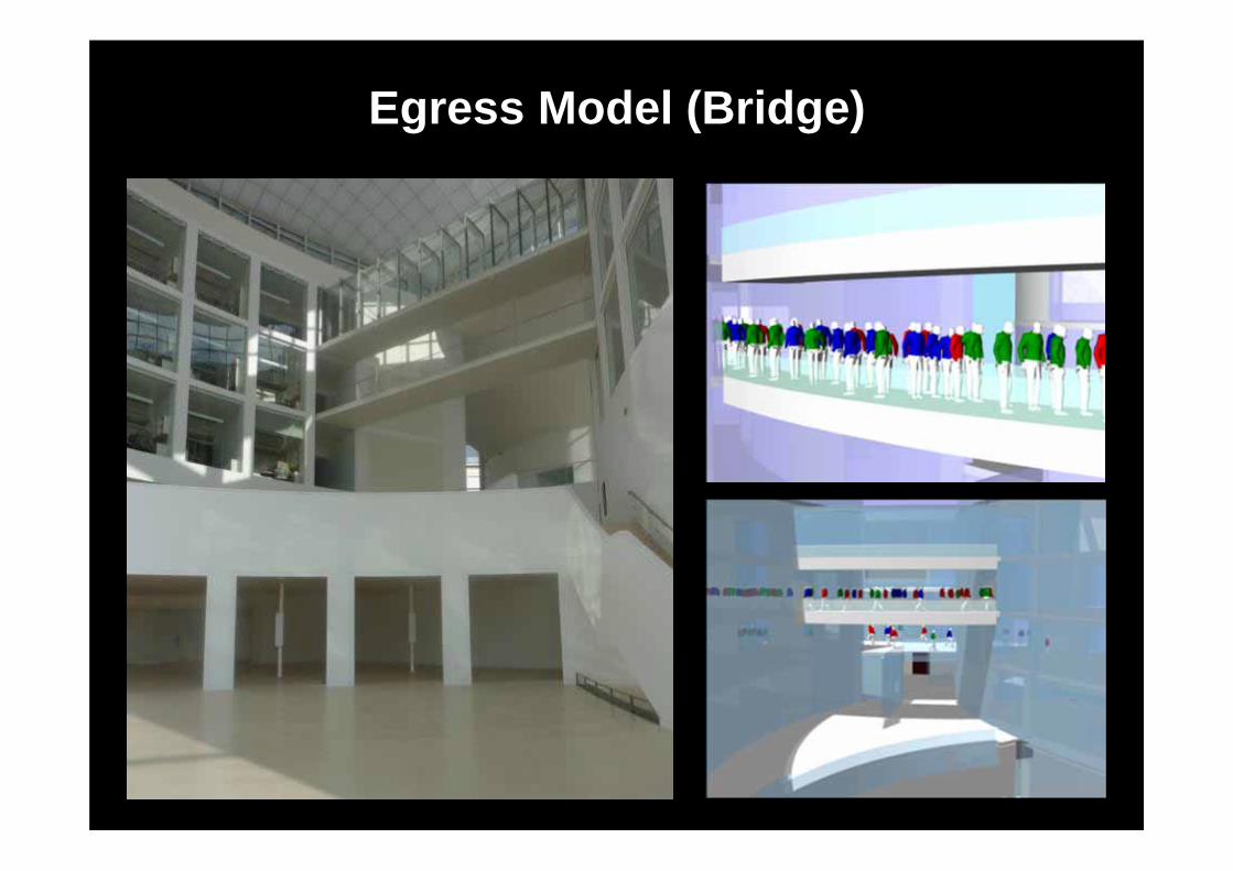
Egress Model (Bridge)
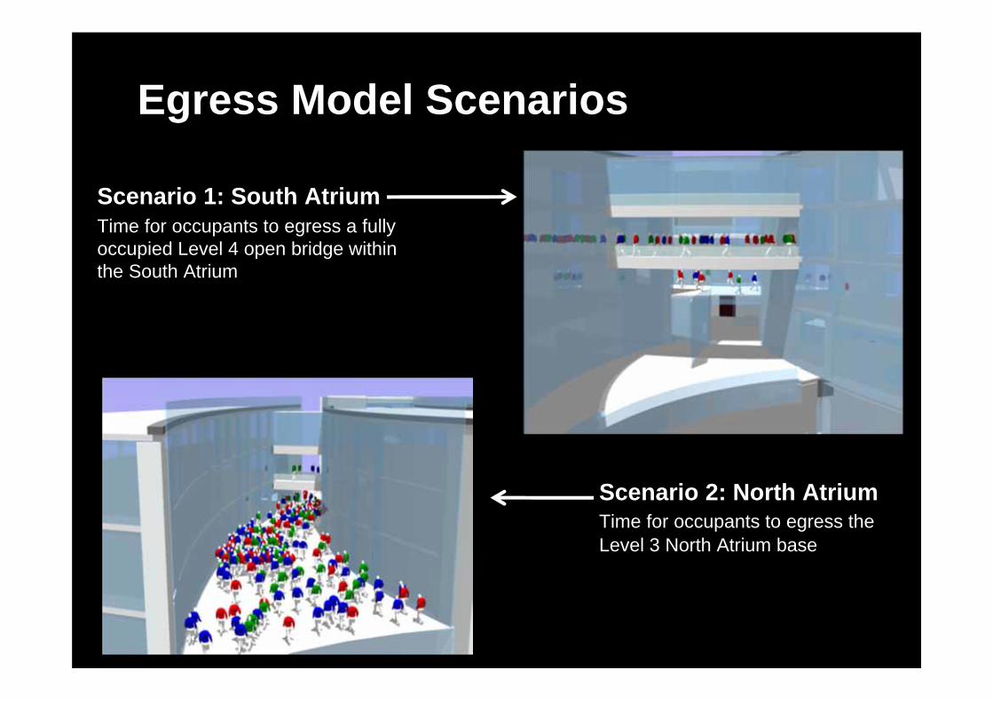
Egress Model Scenarios
Scenario 2: North AtriumTime for occupants to egress the Level 3 North Atrium base
Scenario 1: South AtriumTime for occupants to egress a fully occupied Level 4 open bridge within the South Atrium

Scenario 1 Egress ModelTento obrázek nyní nelze zobrazit.

Evacuation Timeline (Scenario 1)
Egress Model
Safety Factor
Time from fire ignition to detection – 60 seconds (taken from live smoke test Dec 2010)
Delay time to start of egress – 30 seconds (SFPE Handbook Table 3‐13.1)
Egress model time – 67 seconds (1m:07s)
Safety Factor : 50% of egress model time ‐ 34 seconds
TOTAL EVACUATION TIME = 191 seconds (3m:11s)
SFPE Handbook
Live Smoke Test

Results – Fire Model 4th Floor
Conditions maintained tenable for 245 seconds

Results – Fire Model 4th Floor
Conditions maintained tenable for 245 seconds
First failure point
Conditions maintained tenable for 245 seconds

Scenario 2 Egress Model
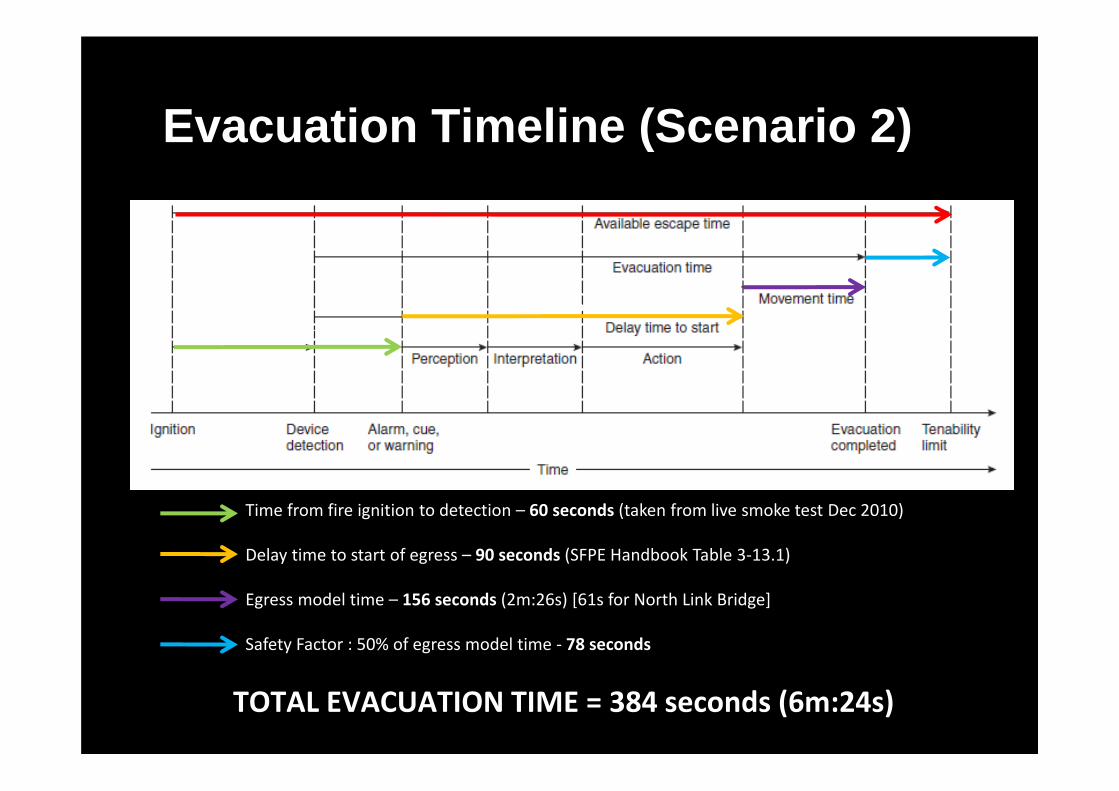
Evacuation Timeline (Scenario 2)
Egress Model
Safety Factor
Time from fire ignition to detection – 60 seconds (taken from live smoke test Dec 2010)
Delay time to start of egress – 90 seconds (SFPE Handbook Table 3‐13.1)
Egress model time – 156 seconds (2m:26s) [61s for North Link Bridge]
Safety Factor : 50% of egress model time ‐ 78 seconds
TOTAL EVACUATION TIME = 384 seconds (6m:24s)
SFPE Handbook
Live Smoke Test

Results – Fire Model 3rd Floor
Conditions maintained tenable for 657 seconds
First failure point
Conditions maintained tenable for 657 seconds

Scenario Total Egress Time (+ 50% code
Safety Factor)
Time to Untenable Conditions
Additional Safety Factor
(over the req’d 50% by code)
1 191 s (3m:11s) 245s (4m:05s) 54s (22%)
2 384 s (6m:24s) 657 s (10m:57s) 273s (42%)
RSET Vs ASET Conclusions
Safe conditions are maintained for longer periods than the minimum required safe egress times by
means of smoke control

Project Examples:
The Rock Triangle,Bury
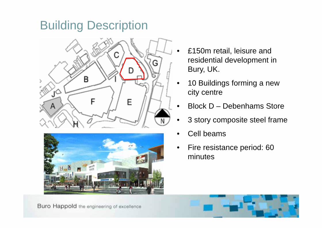
Building Description
• £150m retail, leisure and residential development in Bury, UK.
• 10 Buildings forming a new city centre
• Block D – Debenhams Store
• 3 story composite steel frame
• Cell beams
• Fire resistance period: 60 minutes

Overview of a floor plate
D1
Location of Vulcan model

Methodology and Process
1. Agree methodology with Stakeholders
2. Develop design fires (including cooling)
3. Develop assessment criteria
4. Build geometry of the sub-frames and analyse for different fires
5. Assess connection forces
6. Write a detailed report
7. Present and negotiate with Building Control
Show an equivalent standard of performance to what is seen to be acceptable in prescriptive guidance.

Design Fires
DF1-Standard Fire
DF4-Fast Fire
Hottest fire / Early deflections of unprotected beams /Largest connection forces
0
100
200
300
400
500
600
700
800
900
1000
1100
1200
1300
0 15 30 45 60 75 90 105 120 135 150 165 180Time [Minutes]
Tem
pera
ture
[C]
DF1 - BS 476
DF2 - Low Ventilation
DF3 - Medium Ventilation
DF4 - High Ventilation
DF3-Medium Fire
DF2-Slow Fire• Worst Parametric Fire• Largest vertical
deflections of protected beams
• Critical for columns

Acceptance Criteria
Design Fire Assessment Period Acceptance CriteriaDF1 – Low Ventilation (No Cooling) 60 minutes Check for runaway deflections
Deflection of protected beams < Span/20
Deflection of slab < Span/20 (compartment floor)
Deflection of slab < Span/10 (non-compartment floor)
Connection forces to be provided.
DF2 – Low Ventilation(With Cooling)
60 minutes (compartment floor)
Entire fire duration (non-compartment floor)
DF3 – Medium Ventilation(With Cooling)
DF4 – High Ventilation(With Cooling)
Stability
Integrity
Insulation
– checked by Vulcan
– controlled over deflection limits
– normally not a problem in composite slabs

Material TemperaturesTypical steel temperatures calculated by using EC3-1.2 heat transfer calculations for each part of the section
0
200
400
600
800
1000
1200
0 15 30 45 60 75 90 105 120
Time (minutes)
Tem
pera
ture
(°C
)
Design Fire 2 UnprotBeam-DF2 ProtBeam-DF2 ProtColumn-DF2
Design Fire 3 UnprotBeam-DF3 ProtBeam-DF3 ProtColumn-DF3
Design Fire 4 UnprotBeam-DF4 ProtBeam-DF4 ProtColumn-DF4
T ~
550
°C
T ~
250
°C

Material TemperaturesTypical concrete slab temperatures
0
200
400
600
800
1000
1200
0 30 60 90 120
Time (minutes)
Tem
pera
ture
(°C
)
Design Fire 3
Layer 1 (Bottom)
Layer 2
Layer 3
Layer 4
Layer 5
Layer 6 (Rein)
Layer 7 (Rein)
Layer 8
Layer 9
Layer 10
Layer 11
Layer 12 (Top)

Proposed Fire Protection Regime
A393 mesh

Vulcan Model - Loading
Floor Loads:
Dead Load 6.0kN/m2
Non-perm. Live Load 5.0kN/m2
FLS = 6.0 + 0.8 x 5.0 = 10.0kN/m2
+ Line loads for façade + Line loads for internal walls+ Point loads on columns

Heating regime20°C
Heated

SFE Analyses and ResultsDeflected shape_DF4

SFE Analyses and ResultsMax protected beam deflections
-1000
-800
-600
-400
-200
00 30 60 90 120 150 180 210 240 270 300
Time (minute)
Dis
plac
emen
t (m
m)
Span/20
D1_DF1
D1_DF2
D1_DF3
D1_DF4

SFE Analyses and ResultsMax differential slab deflections
-1200
-1000
-800
-600
-400
-200
0
200
0 30 60 90 120 150 180 210 240 270 300
Time (minute)
Dis
plac
emen
t (m
m)
Span/10
D1_DF1
D1_DF2
D1_DF3
D1_DF4

Connection forces
-2000
-1500
-1000
-500
0
500
1000
1500
2000
0 10 20 30 40 50 60 70 80 90
Time [minutes]
Forc
e [k
N]
Unprotected Beam - fastProtected Beam - fastUnprotected Beam - slowProtected Beam - slow
Tension
Compression
Local buckling in unprotected beams
Cooling phase

Connections in Fire - Cardington
Lower flange buckling occurred during early stages of fire – thermal expansion
Bolt failure occurred during cooling phase

Connections in Fire
Double web cleat for unprotected beams
Endplate connections to protected beams framing into columns
© K.S. Al-Jabri© H. YU

Site Pictures

Conclusions
• About 30% of floor beams can be unprotected
• Some protected secondary beams needed to be stronger
• Reinforcement mesh in slab increased
• Connection design influenced• Significant cost savings
A393 mesh

ME Hotel, London

ME Hotel – Aldwych London
Client:
Architects:
10 storey refurbished hotel and residential building with central atrium

Assessment Methodology1) Hazard identification and risk assessment
2) Structural response modelling at elevated temperature• Define design fire• Determine fire protection scheme• Calculate the heat transfer of the structure• Calculate the response of the structure at the elevated temperature• Assessment criteria – Global stability

Atrium Perimeter
Fire Base
Symmetry
Design Fire Scenarios
Design Fire
Location 2 – “Rear North”D
DDesign Fire
Location 1 – “Nose”
• Risk assessment result: Unsprinklered fire at the atrium base• 2 fire locations have been assessed

Thermal Analysis – Fire model
Design fire – Localised
Incident heat flux calculated based on 3D location of steel members in relations to fire for about 980 members.
Zone 3
Zone 4Zone 4
Zone 5
Zone 6Zone 6
Zone 5
Thermal Plume
Intermittent Flame
Continuous Flame
Zone 1
Zone 2
Cylinder Model for heat transfer

Thermal Analysis – Fire protection
Preliminary protection• Between G floor level to 1st floor
level – 120 mins• Between 1st floor level to 2nd
floor level – 60 mins• Rest of columns running to top
floor – 60 mins• Rest of atrium steelworks
unprotected

Thermal Analysis - Results
Ground Floor
1st Floor – Atrium Base
3rd Floor
4th Floor
5th Floor
6th Floor
7th Floor
8th Floor
9th Floor
10th Floor
2nd Floor
Nose fire Rear north fire

Structural Analysis using Vulcan - Restraints
Thermal restraints from slab Stiff cantilever representing concrete cores

Structural Analysis – Results at Rear North
-15
-10
-5
0
5
10
15
20
0 1000 2000 3000 4000
Dis
plac
emen
t (m
m)
Time (sec)
Nose
Rear North
Rear South

Site images

Conclusion
• Performance based design is sometimes the only way to demonstrate the safety of a building.
• Buy-in from all stakeholders required.
• Sensitivity studies are essential.
• If carefully conducted performance based design can generate significant value for a project.
• Great engineering discipline!


