Fire detection and fire alarm systems - nioec. راحي سيستم هاي...
28
BRITISH STANDARD BS EN 54-4:1998 Incorporating Amendment No. 1 Fire detection and fire alarm systems — Part 4: Power supply equipment The European Standard EN 54-4:1997, with the incorporation of amendment A1:2002, has the status of a British Standard ICS 13.220.20 Copyright British Standards Institution Provided by IHS under license with BSI Not for Resale No reproduction or networking permitted without license from IHS --`,``-`-`,,`,,`,`,,`---
Transcript of Fire detection and fire alarm systems - nioec. راحي سيستم هاي...
Copyright British StandardProvided by IHS under liceNo reproduction or network
BRITISH STANDARD
,,`,`,,
BS EN 54-4:1998Incorporating Amendment No. 1
Fire detection and fire alarm systems —
Part 4: Power supply equipment
--`,``-`-`,,`
The European Standard EN 54-4:1997, with the incorporation of amendment A1:2002, has the status of a British Standard
ICS 13.220.20
`---
���������������� ������������������������������� �������������s Institution nse with BSI
Not for Resaleing permitted without license from IHS

BS EN 54-4:1998
CopProNo
--`,``-`-`,,`,,`,`,,`---
This British Standard, having been prepared under the direction of the Health and Environment Sector Board, was published under the authority of the Standards Board and comes into effect on 15 March 1998
© BSI 27 August 2003
ISBN 0 580 29426 9
yright British Standards Institution vided by IHS under license with BSIreproduction or networking permitted without license from
National foreword This British Standard is the English language version of EN 54-4:1997, including amendment A1:2002. Together with BS EN 54-2:1997, it supersedes BS 5839-4:1988 which will be withdrawn on 1999-04-30. It is one of a series of standards for fire detection and fire alarm systems (see BS EN 54-1 for a full list of current and proposed standards).
The start and finish of text introduced or altered by amendment is indicated in the text by tags !". Tags indicating changes to CEN text carry the number of the CEN amendment. For example, text altered by CEN amendment A1 is indicated by !".
The UK participation in its preparation was entrusted by Technical Committee FSH/12, Fire detection and alarm systems, to Subcommittee FSH/12/3, Control and indicating equipment, which has the responsibility to:
A list of organizations represented on this subcommittee can be obtained on request to its secretary.
Cross-references
The British Standards which implement international or European publications referred to in this document may be found in the BSI Catalogue under the section entitled “International Standards Correspondence Index”, or by using the “Search” facility of the BSI Electronic Catalogue or of British Standards Online.
This publication does not purport to include all the necessary provisions of a contract. Users are responsible for its correct application.
Compliance with a British Standard does not of itself confer immunity from legal obligations.
— aid enquirers to understand the text; — present to the responsible European committee any enquiries on the
interpretation, or proposals for change, and keep the UK interests informed;
— monitor related international and European developments and promulgate them in the UK.
Summary of pages
This document comprises a front cover, an inside front cover, the EN title page,pages 2 to 24, an inside back cover and a back cover.
The BSI copyright notice displayed in this document indicates when the document was last issued.
Amendments issued since publication
Amd. No. Date Comments
14596 27 August 2003 See national foreword
Not for ResaleIHS
Copyright British StandarProvided by IHS under licNo reproduction or netwo
EUROPEAN STANDARD
NORME EUROPÉENNE
EUROPÄISCHE NORM
ds Instituense with
Not for Resalerking permitted without license from IHS
EN 54-4October 1997
+A1December 2002
ICS 13.220.20
Descriptors: Fire equipment, fire detection systems, automatic equipment, safety devices, electric power supply, specifications, tests, inspection, testing conditions, marking
English version
Fire detection and fire alarm systems — Part 4: Power supply equipment
(includes amendment A1:2002)
Systèmes de détection et d’alarme incendie —Partie 4: Equipement d’alimentation électrique (inclut l’amendement A1:2002)
Brandmeldeanlagen —Teil 4: Energieversorgungseinrichtungen (enthält Änderung A1:2002)
--`,``-`-`,,`,,`,`,,`---
This European Standard was approved by CEN on 25 December 1996, amendment A1 was approved by CEN on 23 September 2002.CEN members are bound to comply with the CEN/CENELEC Internal Regulations which stipulate the conditions for giving this European Standard the status of a national standard without any alteration. Up-to-date lists and bibliographical references concerning such national standards may be obtained on application to the Central Secretariat or to any CEN member. This European Standard exists in three official versions (English, French, German). A version in any other language made by translation under the responsibility of a CEN member into its own language and notified to the Central Secretariat has the same status as the official versions. CEN members are the national standards bodies of Austria, Belgium, Czech Republic, Denmark, Finland, France, Germany, Greece, Iceland, Ireland, Italy, Luxembourg, Malta, Netherlands, Norway, Portugal, Spain, Sweden, Switzerland and United Kingdom.
CENEuropean Committee for Standardization
Comité Européen de NormalisationEuropäisches Komitee für Normung
Central Secretariat: rue de Stassart 36, B-1050 Brussels
© 1997 CEN All rights of exploitation in any form and by any means reserved worldwide for CEN national Members.
Ref. No. EN 54-4:1997 + A1:2002 E
tion BSI
EN 54-4:1997
CopProNo
--`,``-`-`,,`,,`,`,,`---
Foreword This European Standard has been prepared by Technical Committee CEN/TC 72, Fire detection and fire alarm systems, the Secretariat of which is held by BSI.
This standard has been prepared in co-operation with the CEA (Comité Européen des Assurances) and with EURALARM (Association of European Manufacturers of Fire and Intruder Alarm Systems).
EN 54 is published in a series of parts. Information on the relationship between this European Standard and other standards of the EN 54 series is given in Annex A of EN 54-1.
This European Standard shall be given the status of a national standard, either by publication of an identical text or by endorsement, at the latest by April 1998, and conflicting national standards shall be withdrawn at the latest by April 1999. In addition, a further 36 months shall be allowed for certification purposes for equipment conforming to the national standard.
According to the CEN/CENELEC Internal Regulations, the national standards organizations of the following countries are bound to implement this European Standard: Austria, Belgium, Czech Republic, Denmark, Finland, France, Germany, Greece, Iceland, Ireland, Italy, Luxembourg, Netherlands, Norway, Portugal, Spain, Sweden, Switzerland and the United Kingdom.
Foreword to amendment A1This document (EN 54-4:1997/A1:2002) has been prepared by Technical Committee CEN/TC 72, Fire detection and fire alarm systems, the Secretariat of which is held by BSI.
This amendment to the European Standard EN 54-4:1997 shall be given the status of a national standard, either by publication of an identical text or by endorsement, at the latest by June 2003, and conflicting national standards shall be withdrawn at the latest by December 2005.
This document has been prepared under a mandate given to CEN by the European Commission and the European Free Trade Association, and supports essential requirements of EU Directive(s).
For relationship with EU Directive(s), see informative Annex ZA which is an integral part of this document.
According to the CEN/CENELEC Internal Regulations, the national standards organizations of the following countries are bound to implement this European Standard: Austria, Belgium, Czech Republic, Denmark, Finland, France, Germany, Greece, Iceland, Ireland, Italy, Luxembourg, Malta, Netherlands, Norway, Portugal, Spain, Sweden, Switzerland and the United Kingdom.
ContentsPage
Foreword 2Introduction 31 Scope 32 Normative references 33 Definitions and abbreviations 43.1 Definitions 43.2 Abbreviations 44 General requirements 44.1 Conformity 44.2 Power sources 45 Functions 55.1 Power supply from the main power source 55.2 Power supply from the standby power source
(battery) 55.3 Charger 55.4 Faults 56 Materials, design and manufacture 66.1 Manufacturer’s declaration 66.2 Mechanical design 66.3 Electrical design 66.4 Power supply interface 67 Documentation 67.1 User’s documentation 67.2 Design documentation 78 Marking 79 Tests 79.1 General 79.2 Functional tests 89.3 Test of the charger and the standby power
source 99.4 Environmental tests 99.5 Cold (operational) 109.6 Damp heat, steady state (operational) 119.7 Impact (operational) 129.8 Vibration, sinusoidal (operational) 129.9 Electrostatic discharges (operational) 139.10 Radiated electromagnetic interference
(operational) 149.11 Voltage transients — Fast transient bursts
(operational) 149.12 Voltage transients — Slow high energy
transients (operational) 159.13 Mains voltage dips and interruptions
(operational) 179.14 Damp heat, steady state (endurance) 179.15 Vibration, sinusoidal (endurance) 18AnnexesAnnex A Text DeletedAnnex ZA (informative) Clauses of this European Standard addressing essential requirements of the Construction Products or other provisions of EU Directives 19Bibliography 24
© BSI 27 August 20032yright British Standards Institution vided by IHS under license with BSI
Not for Resalereproduction or networking permitted without license from IHS

EN 54-4:1997
Copyright British StandardProvided by IHS under liceNo reproduction or network
--`,``-`-`,,`,,`,`,,`---
Introduction
This European Standard is drafted on the basis of functions which are to be provided on all power supplyequipment. The power supply equipment may have its own cabinet, or may be housed with other equipmentof the fire detection and fire alarm system, such as the control and indicating equipment of EN 54-2. A firedetection and fire alarm system may use more than one power supply equipment.
1 Scope
This European Standard specifies requirements, methods of test and performance criteria for power supply equipment (see component L of Figure 1 of EN 54-1) of fire detection and fire alarm systems installed in buildings.
!This standard does not cover the power supplies for self-contained smoke alarms or the battery powered parts of wire-free detection and fire alarm systems."
2 Normative references This European Standard incorporates by dated or undated reference, provisions from other publications. These normative references are cited at the appropriate places in the text and the publications are listed hereafter. For dated references, subsequent amendments to or revisions of any of these publications apply to this European Standard only when incorporated in it by amendment or revision. For undated references the latest edition of the publication referred to applies.
EN 54, Fire detection and fire alarm systems.
EN 54-1:1996, Introduction.
EN 54-2:1997, Control and indicating equipment.
ENV 50142:1994, Electromagnetic compatibility — Basic immunity standard — Surge immunity tests.
IEC 68, Basic environmental testing procedures.
IEC 68-1:1998, General and guidance.
IEC 68-2, Tests.
IEC 68-2-1:1990, Test A: Cold.
IEC 68-2-3:1969 + A1:1984, Test Ca: Damp heat, steady state.
IEC 68-2-6:1982 + A1:1983 + A2:1985, Test Fc and guidance — Vibration, sinusoidal.
IEC 68-2-47:1982, Specification for mounting of components, equipment and other articles for dynamic tests.
IEC 529:1989, Classification of degrees of protection provided by enclosures.
IEC 721, Classification of environmental conditions.
IEC 721-3, Classifications of groups of environmental parameters and their severities.
IEC 721-3-3:1978, Stationary use and weather protected locations.
IEC 801, Electromagnetic compatibility for industrial process measurement and control equipment.
IEC 801-2:1991, Method of evaluating susceptibility to electrostatic charge.
IEC 801-3:1984, Radiated electromagnetic field — Requirements.
IEC 801-4:1988, Electrical fast transient/burst requirements.
IEC 817:1984, Spring-operated impact test apparatus and its calibrations.
IEC 950:1991, Safety of information technology equipment including electrical business equipment.
© BSI 27 August 2003 3s Institution nse with BSI
Not for Resaleing permitted without license from IHS

EN 54-4:1997
CopProNo
3 Definitions and abbreviations
3.1 Definitions
For the purposes of this European Standard the definitions given in EN 54-1 apply together with the following.
3.1.1 float voltage the voltage which when applied to the battery will maintain the battery in a fully charged state. The float voltage is specified by the battery manufacturer
3.1.2 final voltage the lowest recommended voltage to which a battery should be discharged. The final voltage is specified by the battery manufacturer
3.2 Abbreviations For the purposes of this European Standard the following abbreviations apply.
4 General requirements
4.1 Conformity
In order to conform to this standard, the p.s.e. shall meet the requirements of Clauses 4, 5, 6, 7 and 8, shall be tested as described in Clause 9 and shall meet the requirements of the tests.
4.2 Power sources
There shall be at least two power sources for the power supply of a fire detection and fire alarm system; the main power source and the standby power source. The main power source shall be designed to operate from the public electricity supply or an equivalent system.
At least one standby power source shall be a rechargeable battery.
The p.s.e. shall include charging equipment to charge the battery and maintain it in a fully charged state.
Each power source, on its own, shall be capable of operating those parts of the fire detection and fire alarm system for which it is intended.
When the main power source is available, it shall be the exclusive source of power to the fire detection and fire alarm system, other than for currents associated with battery monitoring.
If the main power source fails, the p.s.e. shall be automatically switched over to a standby power source. When the main power source is restored, the p.s.e. shall be automatically switched back.
If the p.s.e. is integrated within other equipment of the fire detection and fire alarm system, the switching from one power source to the other shall not cause any change in status or indications other than those relating to the power supply.
If the p.s.e. is separated from other equipment of the fire detection and fire alarm system, and the switching from one power source to the other causes an interruption in supply of power, the duration of the interruption shall be specified in the manufacturer’s data.
Failure of one of the power sources shall not cause the failure of any other power source or the failure of the supply of power to the system. NOTE The compatibility of the separated p.s.e. with the other equipment, for example, the c.i.e., will be dealt with in EN 54-13 System requirements (to be published).
p.s.e.: power supply equipment (L of Figure 1 of EN 54-1) c.i.e.: control and indicating equipment (B of Figure 1 of EN 54-1)
--`,``-`-`,,`,,`,`,,`---
4 © BSI 27 August 2003yright British Standards Institution vided by IHS under license with BSI
Not for Resalereproduction or networking permitted without license from IHS

EN 54-4:1997
Copyright British StandardProvided by IHS under liceNo reproduction or network
5 Functions
5.1 Power supply from the main power source
When operated from the main power source, the p.s.e.:
a) shall be capable of operating in accordance with its specification given in the manufacturer’s data irrespective of the condition of the standby power source. This includes any charge condition of the battery, or open-circuit or short-circuit of the connection to the battery;
b) shall additionally be able to supply any required charging current for the battery or batteries;
c) may allow battery charging to be limited or interrupted when the p.s.e. is delivering a short duration maximum output load (see note to Table 1).
5.2 Power supply from the standby power source (battery)
5.2.1 When operated from the standby power source, the p.s.e. shall be capable of operating in accordance with the specification given in the manufacturer’s data, irrespective of the condition of the main power source. NOTE The standby and alarm periods required in any specific application should conform to the application guidelines (EN 54-14, to be published).
5.2.2 The battery shall:
a) be rechargeable;
b) be suitable to be maintained in a fully charged state;
c) be constructed for stationary use;
d) be marked with the type designation and date of manufacture.
If the battery is mounted in a cabinet which houses other fire detection and fire alarm equipment, it shall be of the sealed type and shall be mounted in accordance with the manufacturer’s data.
5.3 Charger
5.3.1 The charger shall be designed and rated so that:
a) the battery can be charged automatically;
b) a battery discharged to its final voltage can be recharged to at least 80 % of its rated capacity within 24 hours and to its rated capacity within another 48 hours;
c) the charging characteristics are within the battery manufacturer’s specification over the ambient temperature range of the battery.
5.3.2 Except for currents associated with battery monitoring, the battery shall not discharge through the charger when the charging voltage is below the battery voltage.
5.4 Faults
The p.s.e. shall be capable of recognizing and signalling the following faults:
a) loss of the main power source, within 30 minutes of the occurrence;
b) loss of the standby power source, within 15 minutes of the occurrence;
c) reduction of the battery voltage to less than 0,9 of the final voltage, within 30 minutes of the occurrence;
d) loss of the battery charger, within 30 minutes of the occurrence.
If the p.s.e. is separately housed from the c.i.e., at least a fault output common to the above-mentioned faults shall be provided.
If the p.s.e. is housed within the cabinet of the c.i.e., the above-mentioned faults shall be indicated in accordance with Clause 8 of EN 54-2 either on the c.i.e. or on the p.s.e. itself.
--`,``-`-`,,`,,`,`,,`---
© BSI 27 August 2003 5s Institution nse with BSI
Not for Resaleing permitted without license from IHS

EN 54-4:1997
CopProNo
--`,``-`-`,,`,,`,`,,`---
6 Materials, design and manufacture
6.1 Manufacturer’s declaration
In order to assist the process of design inspection, the manufacturer shall declare the following in writing:
a) that the design has been carried out in accordance with a quality management system which incorporates a set of rules for the design of all elements of the p.s.e.;
b) that the components of the p.s.e. have been selected for the intended purpose and are expected to operate within their specification when the environmental conditions outside the cabinet of the p.s.e conform to class 3K5 of IEC 721-3-3.
6.2 Mechanical design
6.2.1 The cabinet of the p.s.e. shall be of robust construction, consistent with the method of installation recommended in the documentation. It shall meet at least classification IP 30 of IEC 529:1989.
6.2.2 The p.s.e. may be housed either in a separate cabinet or in cabinets associated with other fire detection and fire alarm system equipment.
6.2.3 If the p.s.e. is housed in the c.i.e., manual controls, fuses, calibration elements etc. for disconnection and adjustment of the power sources shall be accessible only at access level 3 of EN 54-2.
6.2.4 If the p.s.e. is not housed in the c.i.e., manual controls, fuses, calibration elements etc. for disconnection and adjustment of the power sources shall be accessible only by the use of a tool or key.
6.2.5 All manual controls, fuses, calibration elements and cable terminals shall be clearly labelled (e.g. to indicate their function, rating or reference to appropriate drawings).
6.2.6 If mandatory indicators required by EN 54-2 are repeated on a separately housed p.s.e., the indicators shall meet the requirements of EN 54-2.
6.3 Electrical design
6.3.1 All outputs shall have appropriate power limitations in order to ensure that in case of external short-circuits no danger exists because of heat production.
6.3.2 The p.s.e. shall have safety characteristics in accordance with IEC 950:1991 for protection against direct and indirect contact, for the separation of the extra low voltage d.c. circuits from the low voltage a.c. circuits and for earthing of metal parts.
6.4 Power supply interface
If the p.s.e. is designed to be used with a c.i.e. contained in a separate cabinet, an interface shall be provided for at least two transmission paths to the c.i.e., such that a short-circuit or interruption in one path does not affect the other.
7 Documentation
7.1 User’s documentation
The manufacturer shall prepare installation and user documentation, which shall be submitted to the testing authority together with the p.s.e. This shall comprise at least the following:
a) a general description of the equipment;
b) technical specifications of the inputs and outputs of the p.s.e., sufficient to permit an assesment of the mechanical and electrical compatibility with other components of the system (as described in EN 54-1) including:
1) power requirements for recommended operation;
2) the maximum and minimum electrical ratings for each input and output;
3) information on the communication parameters employed by the transmission paths;
4) fuse ratings;
6 © BSI 27 August 2003yright British Standards Institution vided by IHS under license with BSI
Not for Resalereproduction or networking permitted without license from IHS

EN 54-4:1997
Copyright British StandardProvided by IHS under liceNo reproduction or network
--`,``-`-`,,`,,`,`,,`---
5) the types and the maximum and minimum capacities of the batteries suitable for use with the p.s.e.;
6) the maximum current drawn from the battery by the p.s.e. when the main power source is disconnected;
c) installation information, including:
1) the suitability for use in various environments;
2) mounting instructions;
3) instructions for connecting inputs and outputs;
d) commissioning instructions;
e) operating instructions;
f) maintenance information.
7.2 Design documentation
The manufacturer shall prepare design documentation, which shall be submitted to the testing authority together with the p.s.e. This documentation shall include drawings, parts lists, circuit diagrams, block diagrams and a functional description to such an extent that the compliance with the requirements of this European Standard can be checked and that a general assessment of the mechanical and electrical design is possible.
8 Marking
The p.s.e shall be clearly marked with the following information:
a) the number of this European Standard (i.e. EN 54-4:1997); b) the name or trademark of the manufacturer or supplier; c) the type number or other designation of the p.s.e.; d) the code or number identifying the production period of the p.s.e.
If the p.s.e is housed in its own cabinet, at least a), b) and c) shall be marked on the outside of this cabinet.
If the p.s.e. is integrated with other fire detection and fire alarm equipment in a common cabinet, then at least a) and b) shall be marked on the outside of the common cabinet.
9 Tests
9.1 General
9.1.1 Standard atmospheric conditions for testing
Unless otherwise stated in a test method, the testing shall be carried out after the test specimen has been allowed to stabilize in the standard atmospheric conditions for testing as described in IEC 68-1:1988 as follows:
The temperature and humidity shall be substantially constant for each environmental test where the standard atmospheric conditions are applied.
9.1.2 Mounting and orientation
Unless otherwise stated in a test procedure, the specimen shall be mounted in its normal orientation by the normal means of mounting indicated by the manufacturer.
temperature: 15 °C to 35 °C; relative humidity: 25 % to 75 %; air pressure: 86 kPa to 106 kPa.
© BSI 27 August 2003 7s Institution nse with BSI
Not for Resaleing permitted without license from IHS
EN 54-4:1997
CopProNo
9.1.3 Electrical connection
If the test procedure requires the specimen to be operating, then unless otherwise specified:
a) it shall be connected to the mains and to a battery of maximum capacity;
b) all inputs and outputs shall be connected to appropriate cables and equipment or to dummy loads corresponding to the maximum load, all as specified by the manufacturer.
9.2 Functional tests
9.2.1 Object of the tests
The object of the functional tests is to check the compliance of the specimen to each requirement in the standard.
9.2.2 Table of functional tests
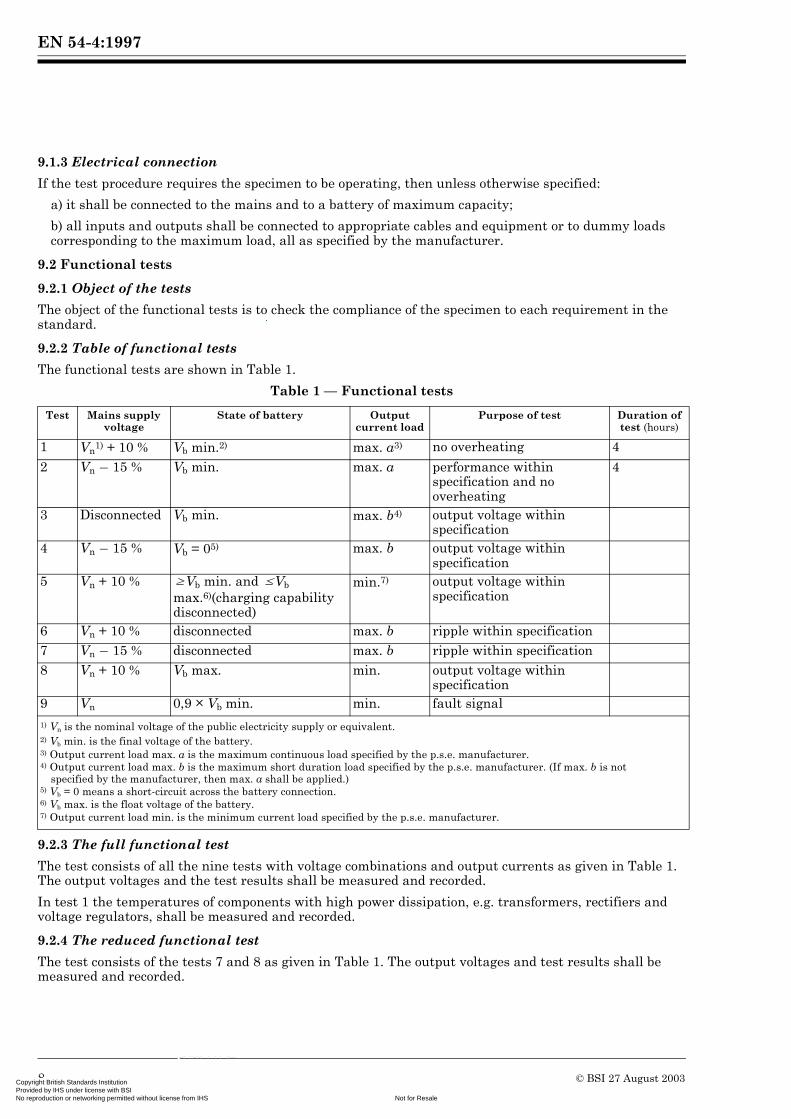
The functional tests are shown in Table 1.
Table 1 — Functional tests
9.2.3 The full functional test
The test consists of all the nine tests with voltage combinations and output currents as given in Table 1. The output voltages and the test results shall be measured and recorded.
In test 1 the temperatures of components with high power dissipation, e.g. transformers, rectifiers and voltage regulators, shall be measured and recorded.
9.2.4 The reduced functional test
The test consists of the tests 7 and 8 as given in Table 1. The output voltages and test results shall be measured and recorded.
Test Mains supply voltage
State of battery Output current load
Purpose of test Duration of test (hours)
1 Vn1) + 10 % Vb min.2) max. a3) no overheating 4
2 Vn p 15 % Vb min. max. a performance within specification and no overheating
4
3 Disconnected Vb min. max. b4) output voltage within specification
4 Vn p 15 % Vb = 05) max. b output voltage within specification
5 Vn + 10 % UVb min. and kVb max.6)(charging capability disconnected)
min.7) output voltage within specification
6 Vn + 10 % disconnected max. b ripple within specification 7 Vn p 15 % disconnected max. b ripple within specification 8 Vn + 10 % Vb max. min. output voltage within
specification 9 Vn 0,9 × Vb min. min. fault signal 1) Vn is the nominal voltage of the public electricity supply or equivalent.2) Vb min. is the final voltage of the battery.3) Output current load max. a is the maximum continuous load specified by the p.s.e. manufacturer.4) Output current load max. b is the maximum short duration load specified by the p.s.e. manufacturer. (If max. b is not
specified by the manufacturer, then max. a shall be applied.) 5) Vb = 0 means a short-circuit across the battery connection.6) Vb max. is the float voltage of the battery.7) Output current load min. is the minimum current load specified by the p.s.e. manufacturer.
8 © BSI 27 August 2003yright British Standards Institution vided by IHS under license with BSI
Not for Resalereproduction or networking permitted without license from IHS
--`,``-`-`,,`,,`,`,,`---

EN 54-4:1997
Copyright British StandardProvided by IHS under liceNo reproduction or network
--`,``-`-`,,`,,`,`,,`---
9.2.5 Requirements
9.2.5.1 In the tests of 9.2.3 and 9.2.4 the output voltages and test results recorded shall not fall outside the range specified by the p.s.e. manufacturer and the requirements in this standard.
9.2.5.2 In test 1 of 9.2.3 the temperatures shall not exceed the maximum temperatures specified by the component manufacturers.
9.3 Test of the charger and the standby power source
9.3.1 Test procedure
9.3.1.1 Discharge the battery to its final voltage at a discharge current of Id = C/20 amperes for lead acid type batteries, or Id = C/10 amperes for nickel cadmium type batteries, where C is the rated ampere hour capacity of the battery, given by the battery manufacturer. !For other battery types, the discharge current shall be that for which the battery manufacturer specifies the rated capacity."
9.3.1.2 Charge the battery for 72 hours with the appropriate charger connected to the nominal mains voltage (Vn).
During this period ensure that the p.s.e. supplies only the current for charging the battery and for operating the c.i.e. of the fire detection and fire alarm system in its normal operating condition. NOTE This current value should be specified by the p.s.e. manufacturer.
9.3.1.3 Repeat the procedure as in 9.3.1.1 and measure the discharge time (T1) in hours.
9.3.1.4 Charge the battery again for 24 h at Vn p 15 %.
During this period ensure that the p.s.e. supplies only the current for charging the battery and for operating the c.i.e. of the fire detection and fire alarm system in its normal operating condition. NOTE. This current value should be specified by the p.s.e. manufacturer.
9.3.1.5 Discharge the battery again to its final voltage at a discharge current as in 9.3.1.1 and measure the discharge time (T2) in hours.
9.3.2 Requirements
The product of the discharge time T1 and the discharge current Id shall be not less than the rated capacity of the battery (C).
The product of the discharge time T2 and the discharge current Id shall be not less than 0,8 × the rated capacity of the battery (C).
9.4 Environmental tests
9.4.1 General
One, two or three specimens may be supplied for environmental testing.
If the p.s.e. is housed in the c.i.e. then the environmental tests described in Clause 15 of EN 54-2 shall be carried out. However, the functional tests required by 9.4.5 of this part of EN 54 shall be carried out in addition to the functional tests required by EN 54-2.
If the p.s.e. is housed separately from the c.i.e. then the tests shown in Table 2 shall be applied.
© BSI 27 August 2003 9s Institution nse with BSI
Not for Resaleing permitted without license from IHS

EN 54-4:1997
CopProNo
Table 2 — Environmental tests
9.4.2 Tests for one specimen
If a single specimen is supplied for environmental testing, the specimen shall be subjected to all the operational tests, which may be carried out in any order. After the operational tests the endurance tests shall be carried out on the same specimen in any order.
9.4.3 Tests for two specimens
If two specimens are supplied for environmental testing, then the first test specimen shall be subjected to all the operational tests, which may be carried out in any order, followed by one of the endurance tests. The second specimen shall be subjected to the other endurance test.
9.4.4 Tests for three specimens
If three specimens are supplied for environmental testing, then one test specimen is subjected to all the operational tests, which may be carried out in any order. The second specimen shall be subjected to one of the endurance tests, and the third specimen shall be subjected to the other endurance test.
9.4.5 Selection of functional tests
A functional test shall be carried out before, after and, when required, during the conditioning of each environmental test, as indicated in the test procedures. For each specimen, the initial functional test (before the conditioning of the first environmental test, on that specimen) and the final functional test (after the conditioning of the last environmental test, on that specimen) shall both be the full functional test of 9.2.3; intermediate functional tests shall be the reduced functional test of 9.2.4. NOTE The functional test after the conditioning of one environmental test may be taken as the functional test before the conditioning of the next environmental test.
9.4.6 Requirements
When subjected to functional test each specimen shall satisfy the requirements of 9.2.5.
The output voltage(s) measured during conditioning shall comply with the manufacturer’s specification.
9.5 Cold (operational)
9.5.1 Object of the test
The object of the test is to demonstrate the ability of the equipment to function correctly at low ambient temperatures appropriate to the anticipated service environment.
9.5.2 Test procedure
9.5.2.1 General
The test procedures with gradual changes in temperature described in IEC 68-2-1:1990 shall be used. Test Ad shall be used for heat-dissipating specimens (as defined in IEC 68-2-1:1990) and test Ab shall be used for non-heat-dissipating specimens.
Test Operational or endurance Clause number
Cold Operational 9.5Damp heat, steady state Operational 9.6Impact Operational 9.7Vibration, sinusoidal Operational 9.8Electrostatic discharge Operational 9.9Radiated electromagnetic interference Operational 9.10Voltage transients — fast transient bursts Operational 9.11Voltage transients — slow high energy surge Operational 9.12Mains voltage dips and interruptions Operational 9.13Damp heat, steady state Endurance 9.14Vibration, sinusoidal Endurance 9.15
--`,``-`-`,,`,,`,`,,`---
10 © BSI 27 August 2003yright British Standards Institution vided by IHS under license with BSI
Not for Resalereproduction or networking permitted without license from IHS
EN 54-4:1997
Copyright British StandardProvided by IHS under liceNo reproduction or network
9.5.2.2 Initial examination
Before conditioning, subject the specimen to the functional test required by 9.4.5.
9.5.2.3 State of the specimen during conditioning
The specimen shall be mounted as required by 9.1.2, be connected as required by 9.1.3 and be operating.
9.5.2.4 Conditioning
Apply the following severity of conditioning:
a) temperature: p5 °C ± 3 °C;
b) duration: 16 h.
9.5.2.5 Measurements during conditioning
Monitor the specimen during the conditioning period to check that output voltages are within the specifications. During the last hour of the conditioning period, subject the specimen to the reduced functional test.
9.5.2.6 Final measurements
After the recovery period, subject the specimen to the functional test required by 9.4.5 and inspect it visually for mechanical damage both externally and internally.
9.6 Damp heat, steady state (operational)
9.6.1 Object of the test
The object of the test is to demonstrate the ability of the equipment to function correctly at high relative humidities (without condensation), which may occur for short periods in the service environment.
9.6.2 Test procedure
9.6.2.1 General
The test procedure described in IEC 68-2-3:1969 shall be used.
9.6.2.2 Initial examination
Before conditioning, subject the specimen to the functional test required by 9.4.5.
9.6.2.3 State of the specimen during conditioning
The specimen shall be mounted as required by 9.1.2, be connected as required by 9.1.3 and be operating.
9.6.2.4 Conditioning
Apply the following severity of conditioning:
a) temperature: 40 °C ± 2 °C;
b) relative humidity: ;
c) duration: 4 days.
Precondition the specimen at the conditioning temperature (40 °C ± 2 °C) until temperature stability has been reached to prevent the formation of water droplets on the specimen.
9.6.2.5 Measurements during conditioning
Monitor the specimen during the conditioning period to check that output voltages are within the specifications. During the last hour of the conditioning period, subject the specimen to the reduced functional test.
9.6.2.6 Final measurements
After the recovery period, subject the specimen to the functional test required by 9.4.5 and inspect it visually for mechanical damage both externally and internally.
93 2+ 3–
%
--`,``-`-`,,`,,`,`,,`---
© BSI 27 August 2003 11s Institution nse with BSI
Not for Resaleing permitted without license from IHS
EN 54-4:1997
CopProNo
9.7 Impact (operational)
9.7.1 Object of the test
The object of the test is to demonstrate the immunity of the equipment to mechanical impacts upon the surface, which it may sustain in the normal service environment and which it can reasonably be expected to withstand.
9.7.2 Test procedure
9.7.2.1 General
Apply the test apparatus and procedure described in IEC 817:1984.
9.7.2.2 Initial examination
Before conditioning, subject the specimen to the functional test required by 9.4.5.
9.7.2.3 State of the specimen during conditioning
The specimen shall be mounted as required by 9.1.2, be connected as required by 9.1.3 and be operating.
9.7.2.4 Conditioning
Apply impacts to all surfaces of the specimen which are accessible without special tools.
For all such surfaces three blows shall be applied to any point(s) considered likely to cause damage to or impair the operation of the specimen.
Care should be taken to ensure that the results from a series of three blows do not influence subsequent series.
In case of doubts, the defect shall be disregarded and a further three blows shall be applied to the same position on a new specimen.
Apply the following severity of conditioning:
a) impact energy: (0,5 ± 0,04) J;
b) number of impacts per point: 3.
9.7.2.5 Measurements during conditioning
Monitor the specimen during the conditioning periods to check that output voltages stay within the specifications and ensure that results of three blows do not influence subsequent series.
9.7.2.6 Final measurements
After the recovery period, subject the specimen to the functional test required by 9.4.5 and inspect it visually for mechanical damage both externally and internally.
9.8 Vibration, sinusoidal (operational)
9.8.1 Object of the test
The object of the test is to demonstrate the immunity of the equipment to vibrations at levels appropriate to the service environment.
9.8.2 Test procedure
9.8.2.1 General
The test procedure described in IEC 68-2-6:1982 shall be used. NOTE The vibration operational test may be combined with the vibration endurance test, so that the specimen is subjected to the operational test conditioning followed by the endurance test conditioning in each axis.
9.8.2.2 Initial examination
Before conditioning, subject the specimen to the functional test required by 9.4.5.
9.8.2.3 State of the specimen during conditioning
The specimen shall be mounted as required by 9.1.2 and in accordance with IEC 68-2-47:1982, be connected as required by 9.1.3 and be operating.
12 © BSI 27 August 2003yright British Standards Institution vided by IHS under license with BSI
Not for Resalereproduction or networking permitted without license from IHS
--`,``-`-`,,`,,`,`,,`---

EN 54-4:1997
Copyright British StandardProvided by IHS under liceNo reproduction or network
9.8.2.4 Conditioning
Subject the specimen to vibration in each of the three mutually perpendicular axes in turn, one of which is perpendicular to the plane of mounting of the specimen.
Apply the following severity of conditioning:
a) frequency range: 10 Hz to 150 Hz;
b) acceleration amplitude: 0,981 m·sp2 (0,1 gn);
c) number of axes: 3;
d) number of sweep cycles per axis: 1 for each functional condition.
9.8.2.5 Measurements during conditioning
Monitor the specimen during the conditioning periods to check that output voltages stay within the specifications.
9.8.2.6 Final measurements
After the recovery period, subject the specimen to the functional test required by 9.4.5 and inspect it visually for mechanical damage both externally and internally.
9.9 Electrostatic discharges (operational)
9.9.1 Object of the test
The object of the test is to demonstrate the immunity of the equipment to electrostatic discharges caused by personnel, who may have become electrostatically charged, touching the equipment or other equipment near by.
9.9.2 Test procedure
9.9.2.1 General
The test procedure for type tests performed in laboratories shall be used, as described in IEC 801-2:1991.
The tests consist of:
a) direct electrostatic discharges onto parts of the equipment accessible to the operator (i.e. at access level 2, as specified in EN 52-2);
b) indirect electrostatic discharges onto adjacent coupling planes.
9.9.2.2 Initial examination
Before conditioning, subject the specimen to the functional test required by 9.4.5.
9.9.2.3 State of the specimen during conditioning
The specimen shall be mounted as required by 9.1.2, be connected as required by 9.1.3 and be operating.
9.9.2.4 Conditioning
Apply the following severity of conditioning:
9.9.2.5 Measurements during conditioning
Monitor the specimen during the conditioning period to check that output voltages stay within the specifications.
a) test voltage: 2 kV, 4 kV and 8 kV for air discharges at insulating surfaces; 2 kV, 4 kV and 6 kV for contact discharges to conducting surfaces and to coupling planes;
b) polarity: positive and negative; c) number of discharges: 10 per pre-selected spot; d) time between successive discharges: at least 1 s.
--`,``-`-`,,`,,`,`,,`---
© BSI 27 August 2003 13s Institution nse with BSI
Not for Resaleing permitted without license from IHS
EN 54-4:1997
CopProNo
--`,``-`-`,,`,,`,`,,`---
9.9.2.6 Final measurements
After conditioning, subject the specimen to the functional test required by 9.4.5 and inspect it visually for mechanical damage both externally and internally.
9.10 Radiated electromagnetic interference (operational)
9.10.1 Object of the test
The object of the test is to demonstrate the immunity of the equipment to electromagnetic fields such as those produced by portable radio transceivers, etc.
9.10.2 Test procedure
9.10.2.1 General
The type test procedure of IEC 801-3:1984 shall be used.
9.10.2.2 Initial examination
Before conditioning, subject the specimen to the functional test required by 9.4.5.
9.10.2.3 State of the specimen during conditioning
The specimen shall be mounted as required by 9.1.2, be connected as required by 9.1.3 and be operating.
9.10.2.4 Conditioning
Apply the following severity of conditioning:
a) frequency range: 1 MHz – 1 GHz;
b) field strength: 10 V/m;
c) sinusoidal amplitude modulation: 80 % at 1 kHz.
9.10.2.5 Measurements during conditioning
Monitor the specimen during the conditioning period to check that output voltages stay within the specifications.
9.10.2.6 Final measurement
After conditioning, subject the specimen to the functional test required by 9.4.5 and inspect it visually for mechanical damage both externally and internally.
9.11 Voltage transients — Fast transient bursts (operational)
9.11.1 Object of the test
The object of the test is to demonstrate the immunity of the equipment to bursts of fast low energy transients which may be produced by relays, contactors, switching inductive loads etc. and may be induced into signal and data circuits.
9.11.2 Test procedure
9.11.2.1 General
Use the test procedure described in IEC 801-4:1988.
The test procedures for type tests performed in laboratories shall be used.
9.11.2.2 Initial examination
Before conditioning, subject the specimen to the functional test required by 9.4.5.
9.11.2.3 State of the specimen during conditioning
The specimen shall be mounted as required by 9.1.2, be connected as required by 9.1.3 and be operating.
14 © BSI 27 August 2003yright British Standards Institution vided by IHS under license with BSI
Not for Resalereproduction or networking permitted without license from IHS

EN 54-4:1997
Copyright British StandardProvided by IHS under liceNo reproduction or network
9.11.2.4 Conditioning
Apply the following severity of conditioning:
a) 2 kV to mains power supply terminals of the associated p.s.e. and protective earth conductor via a coupling/decoupling network;
b) 1 kV to each type of d.c. extra low voltage terminals and other inputs, signal-, data- and control-terminals via a capacitive coupling clamp.
9.11.2.5 Measurements during conditioning
Monitor the specimen during the conditioning period to check that output voltages stay within the specifications.
9.11.2.6 Final measurement
After conditioning, subject the specimen to the functional test required by 9.4.5 and inspect it visually for mechanical damage both externally and internally.
9.12 Voltage transients — Slow high energy transients (operational)
9.12.1 Object of the test
The object of the test is to demonstrate the immunity of the equipment to relatively slow high energy transients which may be included in power and signal cables from lightning strikes in the vicinity or by switching in power distribution systems or large voltage networks, including the switching of large capacitor batteries.
9.12.2 Test procedure
9.12.2.1 General
The test apparatus and procedure shall be generally as described in ENV 50142:1994 and hereafter.
A.C. mains power lines shall be subjected to transients injected by both line-to-line and line-to-ground coupling modes. With line-to-ground coupling the transients shall be injected via a 10 7 series resistor. The length of the power lines between the p.s.e. and the coupling/decoupling network shall be k2 m. At least 20 pulses of each polarity shall be applied at each of the voltage levels shown for the appropriate severity. These pulses shall be synchronized with the mains voltage wave such that at least 5 pulses are applied at each of the zero crossing points and at the maximum and minimum points. The pulses may be applied at a maximum rate of 1 per 5 s, however, it is necessary to ensure that any failures are not due to applying the pulses too frequently, and that if this is not clear then the failed devices should be replaced and the test repeated with the pulses applied at a rate of less than 1 per min.
Extra low voltage and signal lines shall be subjected to transients injected by line-to-ground coupling mode only, via a 40 7 series resistor. If the equipment has a large number of identical inputs/outputs (e.g. detector loops) then representative samples of each type of input/output may be selected for testing. The length of the signal lines between the p.s.e. and coupling/decoupling network(s) shall be k2 m. However, if it is specified that certain signal lines must only be connected with screened cables, then in these cases the transients shall be applied to the screen of a 20 m length of screened cable as shown in Figure 1. At least 5 pulses of each polarity shall be applied at each of the voltage levels shown for the appropriate severity. The pulses may be applied at a maximum rate of 1 per 5 s, however, it is necessary to ensure that any failures are not due to applying the pulses too frequently, and that if this is not clear then the failed devices should be replaced and the test repeated with pulses applied at a rate of less than 1 per min.
--`,``-`-`,,`,,`,`,,`---
© BSI 27 August 2003 15s Institution nse with BSI
Not for Resaleing permitted without license from IHS

EN 54-4:1997
CopProNo
--`,``-`-`,,`,,`,`,,`---
9.12.2.2 Initial examination
Before conditioning, subject the specimen to the functional test required by 9.4.5.
9.12.2.3 State of the specimen during conditioning
The specimen shall be arranged and connected in accordance with the manufacturer’s installation instructions and shall be operating. Apart from the manufacturer’s specified earth connections, the specimen and interconnecting cables shall be insulated from the ground reference.
9.12.2.4 Conditioning
Apply the following severity of conditioning:
Key
A: test generator;
B: protection equipment;
C: 10 nF capacitor (included if the screen is not connected to the equipment under test or if the equipment under test is not earthed);
D: 20 m of screened cable, bundled non-inductively;
E: earth reference;
F: equipment under test;
G: earthing connections in accordance with the manufacturer’s instructions;
L: 20 mH inductor (2 of).
Figure 1 — Transient injection into screened cable
a) for a.c. mains power lines: line-to-line: 500 V and 1 kV; line-to-ground: 500 V, 1 kV and 2 kV via a 10 7 series resistor.
NOTE The above levels are open-circuit voltages.
b) for d.c. extra low voltage and signal lines: line-to-ground: 500 V and 1 kV via a 40 7 series resistor.
NOTE The above levels are open-circuit voltages.
16 © BSI 27 August 2003yright British Standards Institution vided by IHS under license with BSI
Not for Resalereproduction or networking permitted without license from IHS
EN 54-4:1997
Copyright British StandardProvided by IHS under liceNo reproduction or network
--`,``-`-`,,`,,`,`,,`---
9.12.2.5 Measurements during conditioning
Monitor the specimen during the conditioning periods to check that output voltages stay within the specifications.
9.12.2.6 Final measurements
After conditioning, subject the specimen to the functional test required by 9.4.5.
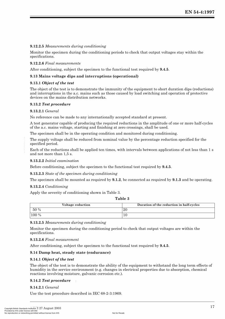
9.13 Mains voltage dips and interruptions (operational)
9.13.1 Object of the test
The object of the test is to demonstrate the immunity of the equipment to short duration dips (reductions) and interruptions in the a.c. mains such as those caused by load switching and operation of protective devices on the mains distribution networks.
9.13.2 Test procedure
9.13.2.1 General
No reference can be made to any internationally accepted standard at present.
A test generator capable of producing the required reductions in the amplitude of one or more half-cycles of the a.c. mains voltage, starting and finishing at zero crossings, shall be used.
The specimen shall be in the operating condition and monitored during conditioning.
The supply voltage shall be reduced from nominal value by the percentage reduction specified for the specified period.
Each of the reductions shall be applied ten times, with intervals between applications of not less than 1 s and not more than 1,5 s.
9.13.2.2 Initial examination
Before conditioning, subject the specimen to the functional test required by 9.4.5.
9.13.2.3 State of the specimen during conditioning
The specimen shall be mounted as required by 9.1.2, be connected as required by 9.1.3 and be operating.
9.13.2.4 Conditioning
Apply the severity of conditioning shown in Table 3.
Table 3
9.13.2.5 Measurements during conditioning
Monitor the specimen during the conditioning period to check that output voltages are within the specifications.
9.13.2.6 Final measurement
After conditioning, subject the specimen to the functional test required by 9.4.5.
9.14 Damp heat, steady state (endurance)
9.14.1 Object of the test
The object of the test is to demonstrate the ability of the equipment to withstand the long term effects of humidity in the service environment (e.g. changes in electrical properties due to absorption, chemical reactions involving moisture, galvanic corrosion etc.).
9.14.2 Test procedure
9.14.2.1 General
Use the test procedure described in IEC 68-2-3:1969.
Voltage reduction Duration of the reduction in half-cycles
50 % 20 100 % 10
© BSI 27 August 2003 17s Institution nse with BSI
Not for Resaleing permitted without license from IHS
EN 54-4:1997
CopProNo
9.14.2.2 Initial examination
Before conditioning, subject the specimen to the functional test required by 9.4.5.
9.14.2.3 State of the specimen during conditioning
The specimen shall be mounted as required by 9.1.2. The specimen shall not be supplied with power during the conditioning.
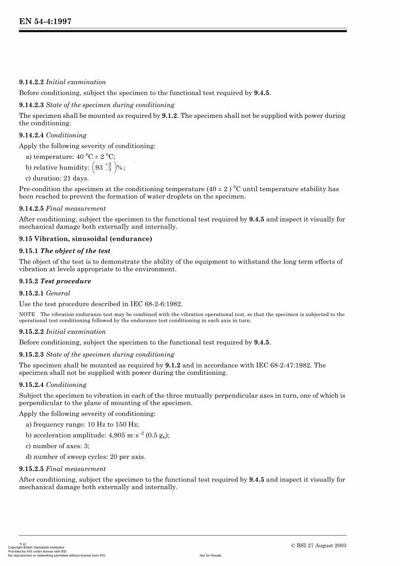
9.14.2.4 Conditioning
Apply the following severity of conditioning:
a) temperature: 40 °C ± 2 °C;
b) relative humidity: ;
c) duration: 21 days.
Pre-condition the specimen at the conditioning temperature (40 ± 2 ) °C until temperature stability has been reached to prevent the formation of water droplets on the specimen.
9.14.2.5 Final measurement
After conditioning, subject the specimen to the functional test required by 9.4.5 and inspect it visually for mechanical damage both externally and internally.
9.15 Vibration, sinusoidal (endurance)
9.15.1 The object of the test
The object of the test is to demonstrate the ability of the equipment to withstand the long term effects of vibration at levels appropriate to the environment.
9.15.2 Test procedure
9.15.2.1 General
Use the test procedure described in IEC 68-2-6:1982. NOTE The vibration endurance test may be combined with the vibration operational test, so that the specimen is subjected to the operational test conditioning followed by the endurance test conditioning in each axis in turn.
9.15.2.2 Initial examination
Before conditioning, subject the specimen to the functional test required by 9.4.5.
9.15.2.3 State of the specimen during conditioning
The specimen shall be mounted as required by 9.1.2 and in accordance with IEC 68-2-47:1982. The specimen shall not be supplied with power during the conditioning.
9.15.2.4 Conditioning
Subject the specimen to vibration in each of the three mutually perpendicular axes in turn, one of which is perpendicular to the plane of mounting of the specimen.
Apply the following severity of conditioning:
a) frequency range: 10 Hz to 150 Hz;
b) acceleration amplitude: 4,905 m·s–2 (0.5 gn);
c) number of axes: 3;
d) number of sweep cycles: 20 per axis.
9.15.2.5 Final measurement
After conditioning, subject the specimen to the functional test required by 9.4.5 and inspect it visually for mechanical damage both externally and internally.
93 2+ 3–
%
--`,``-`-`,,`,,`,`,,`---
18 © BSI 27 August 2003yright British Standards Institution vided by IHS under license with BSI
Not for Resalereproduction or networking permitted without license from IHS
EN 54-4:1997
Copyright British StandardProvided by IHS under liceNo reproduction or network
--`,``-`-`,,`,,`,`,,`--
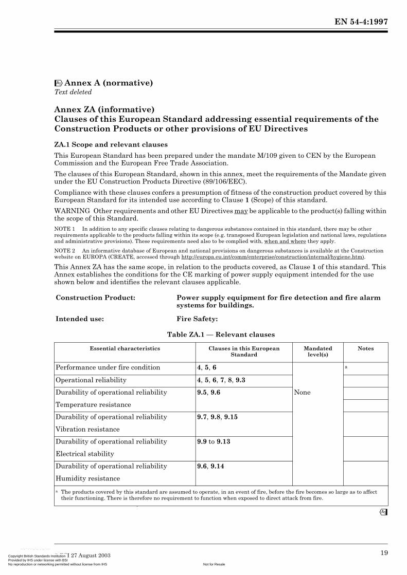
!Annex A (normative) Text deleted
Annex ZA (informative) Clauses of this European Standard addressing essential requirements of the Construction Products or other provisions of EU Directives
ZA.1 Scope and relevant clauses
This European Standard has been prepared under the mandate M/109 given to CEN by the European Commission and the European Free Trade Association.
The clauses of this European Standard, shown in this annex, meet the requirements of the Mandate given under the EU Construction Products Directive (89/106/EEC).
Compliance with these clauses confers a presumption of fitness of the construction product covered by this European Standard for its intended use according to Clause 1 (Scope) of this standard.
WARNING Other requirements and other EU Directives may be applicable to the product(s) falling within the scope of this Standard.NOTE 1 In addition to any specific clauses relating to dangerous substances contained in this standard, there may be other requirements applicable to the products falling within its scope (e.g. transposed European legislation and national laws, regulations and administrative provisions). These requirements need also to be complied with, when and where they apply.
NOTE 2 An informative database of European and national provisions on dangerous substances is available at the Construction website on EUROPA (CREATE, accessed through http://europa.eu.int/comm/enterprise/construction/internal/hygiene.htm).
This Annex ZA has the same scope, in relation to the products covered, as Clause 1 of this standard. This Annex establishes the conditions for the CE marking of power supply equipment intended for the use shown below and identifies the relevant clauses applicable.
Table ZA.1 — Relevant clauses
"
Construction Product: Power supply equipment for fire detection and fire alarm systems for buildings.
Intended use: Fire Safety:
Essential characteristics Clauses in this European Standard
Mandated level(s)
Notes
Performance under fire condition 4, 5, 6 a
Operational reliability 4, 5, 6, 7, 8, 9.3
Durability of operational reliability 9.5, 9.6 None
Temperature resistance
Durability of operational reliability 9.7, 9.8, 9.15
Vibration resistance
Durability of operational reliability 9.9 to 9.13
Electrical stability
Durability of operational reliability 9.6, 9.14
Humidity resistance
a The products covered by this standard are assumed to operate, in an event of fire, before the fire becomes so large as to affect their functioning. There is therefore no requirement to function when exposed to direct attack from fire.
© BSI 27 August 2003 19s Institution nse with BSI
Not for Resaleing permitted without license from IHS
-

EN 54-4:1997
CopProNo
--`,``-`-`,,`,,`,`,,`---
!ZA.2 Procedures for the attestation of conformity of power supply equipment covered by this standard
ZA.2.1 System of attestation of conformity
The mandate requires that the attestation of conformity system to be applied shall be that shown in Table ZA.2.
Table ZA.2 — Attestation of conformity system
This requires:
a) tasks to be provided by the manufacturer:
1) factory production control (see ZA.2.2b);
2) testing of samples taken at the factory by the manufacturer in accordance with a prescribed test plan;
b) tasks to be undertaken under the authority of a Notified Production Certification Body1):
1) type testing of the product;
2) inspection of the factory and factory production control;
3) continuous/periodic surveillance, assessment and approval of the factory production control.
ZA.2.2 Evaluation of conformity
The evaluation of conformity of power supply equipment covered by this European Standard shall be by the following:
a) Type testing
Type testing of the product shall be carried out in accordance with the clauses shown in Table ZA.1. The products tested shall be representative of the manufacturer’s normal production with regard to their construction, operation and calibration. Tests previously performed in accordance with the provisions of this standard may be taken into account providing that they were made to the same system of attestation of conformity on the same product or products of similar design, construction and functionality, such that the results may be considered applicable to the product in question. Wherever a change, for example in the product design, materials or supplier of the components or of the production process occurs, which could change significantly one or more of the characteristics, the type testing shall be repeated for the relevant product performance.
b) Factory production control
The manufacturer shall establish, document and maintain a permanent factory production control system to ensure that the products placed on the market conform with the stated performance characteristics. The factory production control system shall consist of procedures, regular inspections and tests and/or assessments and the use of the results to control incoming materials or components, equipment, the production process and the product.
The production control procedure shall be adequately extensive and detailed so that the conformity of the products is made apparent to the manufacturer and so that irregularities can be detected at the earliest possible stage."
Product Intended use Levels or classes Attestation of conformity system
Fire detection/Fire alarm:
Power supply equipment Fire safety None 1
System 1: See CPD Annex III.2.(i), without audit-testing of samples.
1) !A Notified Product Certification Body is an approved product certification body notified to the Commission by a member state, for this purpose, in accordance with article 18 of the Construction Products Directive (89/106/EEC)."
20 © BSI 27 August 2003yright British Standards Institution vided by IHS under license with BSI
Not for Resalereproduction or networking permitted without license from IHS

EN 54-4:1997
Copyright British StandardProvided by IHS under liceNo reproduction or network
--`,``-`-`,,`,,`,`,,`---
!A factory production control system conforming with the requirements of EN ISO 9001, and made specific to the requirements of this standard, should be considered to satisfy the above requirements.
The production control procedure shall be recorded in a manual, which shall be made available for inspection.
The factory production control shall be recorded. Theses records shall be available for inspection and shall include at least the following:
1) identification of the product tested;
2) the dates of sampling;
3) the test methods applied;
4) the test and inspection results;
5) the date of tests;
6) the identification of the responsible authority within the factory;
7) calibration records;
8) actions taken.
ZA.3 CE Marking and labelling and accompanying documentation
The CE-marking symbol (in accordance with Directive 93/68/EEC) shall be placed on the product and be accompanied by:
i) the identification number of the Notified Production Certification Body;
ii) the number of the EC certificate of conformity.
The CE marking symbol shall in addition be shown on the accompanying commercial documentation supplemented by:
a) the identification number of the Notified Product Certification Body;
b) the name or identifying mark and registered address of the manufacturer;
c) the last two digits of the year in which the marking was affixed;
d) the number of the EC certificate of conformity;
e) the reference to this European Standard (EN 54-4);
f) the description of the construction product (e.g. Power supply equipment for fire detection and fire alarm systems for buildings);
g) the type/model designation of the product;
h) the data required by Clause 7.1 or a reference to a document, which shall be uniquely identifiable and available from the manufacturer, containing these data.
Where the product exceeds the minimum performance levels stated in this standard, and where the manufacturer so desires, the CE marking may be accompanied by an indication of the parameter(s) concerned and the actual test result(s).
Figure ZA.1 shows an example of the information to be given on the accompanying commercial documentation."
© BSI 27 August 2003 21s Institution nse with BSI
Not for Resaleing permitted without license from IHS

EN 54-4:1997
CopProNo
--`,``-`-`,,`,,`,`,,`
!
ZA.4 EC Certification and declaration of conformity
The manufacturer, or his agent established in the EEA, shall prepare and retain a declaration of conformity, which authorizes the affixing of the CE marking. This declaration shall include:
— the name and address of the manufacturer, or his authorized representative established in the EEA, and the place of production:— the description of the construction product (i.e. power supply equipment for fire detection and fire alarm systems for buildings);— the type/model designation of the product;— the provisions to which the product conforms (i.e. Annex ZA of this European Standard);— any particular conditions applicable to the use of the product [if necessary];— the name and address (or identification number) of the Notified Product Certification Body;— the name of and position held by the person empowered to sign the declaration on behalf of the manufacturer or of his authorized representative."
Figure ZA.1 — Example of CE marking information on the accompanying commercial documentation
0123
AnyCo Ltd, P.O. Box 21, B1050
01
0123 – CPD – 001
EN 54-4
Power supply equipment for fire detection and fire alarmsystems for buildings
ABC 123
Technical data: see Doc.123/2000 held by themanufacturer.
---
22 © BSI 27 August 2003yright British Standards Institution vided by IHS under license with BSI
Not for Resalereproduction or networking permitted without license from IHS
EN 54-4:1997
Copyright British StandardProvided by IHS under liceNo reproduction or network
--`,``-`-`,,`,,`,`,,`---
!The declaration shall contain a certificate of conformity with the following information:
— the name and address of the Notified Product Certification Body;— the certificate number;— the name and address of the manufacturer, or his authorized representative established in the EEA;— the description of the construction product (i.e. power supply equipment for fire detection and fire alarm systems for buildings);— the type/model designation of the product;— the provisions to which the product conforms (i.e. Annex ZA of this European Standard); — any particular conditions applicable to the use of the product [if necessary];— any conditions and period of validity of the certificate, where applicable;— the name of and position held by the person empowered to sign the certificate.
The above mentioned declaration and certificate shall be presented (if requested) in the official language or languages of the Member State in which the product is to be used."
© BSI 27 August 2003 23s Institution nse with BSI
Not for Resaleing permitted without license from IHS

EN 54-4:1997
CopProNo
!
Bibliography
EN ISO 9001, Quality management systems — Requirements (ISO 9001).
EU Directive 93/68/EC, COUNCIL DIRECTIVE 93/68/EEC of 22 July 1993 amending Directives 87/404/EEC (simple pressure vessels), 88/378/EEC (safety of toys), 89/106/EEC (construction products), 89/336/EEC (electromagnetic compatibility), 89/392/EEC (machinery), 89/686/EEC (personal protective equipment), 90/384/EEC (non-automatic weighing instruments), 90/385/EEC (active implantable medicinal devices), 90/396/EEC (appliances burning gaseous fuels), 91/263/EEC (telecommunications terminal equipment), 92/42/EEC (new hot-water boilers fired with liquid or gaseous fuels) and 73/23/EEC (electrical equipment designed for use within certain voltage limits)."
24 © BSI 27 August 2003yright British Standards Institution vided by IHS under license with BSI
Not for Resalereproduction or networking permitted without license from IHS
--`,``-`-`,,`,,`,`,,`---

Copyright British StandardProvided by IHS under liceNo reproduction or network
blanks Institution nse with BSI
Not for Resaleing permitted without license from IHS
--`,``-`-`,,`,,`,`,,`---
CopProNo
BS EN 54-4:1998
vr
BSI
389 Chiswick High Road
London
W4 4AL
yright British Standards Institution ided by IHS under license with BSIeproduction or networking permitted without license from IHS
BSI — British Standards InstitutionBSI is the independent national body responsible for preparing British Standards. It presents the UK view on standards in Europe and at the international level. It is incorporated by Royal Charter.
Revisions
British Standards are updated by amendment or revision. Users of British Standards should make sure that they possess the latest amendments or editions.
It is the constant aim of BSI to improve the quality of our products and services. We would be grateful if anyone finding an inaccuracy or ambiguity while using this British Standard would inform the Secretary of the technical committee responsible, the identity of which can be found on the inside front cover. Tel: +44 (0)20 8996 9000. Fax: +44 (0)20 8996 7400.
BSI offers members an individual updating service called PLUS which ensures that subscribers automatically receive the latest editions of standards.
Buying standards
Orders for all BSI, international and foreign standards publications should be addressed to Customer Services. Tel: +44 (0)20 8996 9001. Fax: +44 (0)20 8996 7001. Email: [email protected]. Standards are also available from the BSI website at http://www.bsi-global.com.
In response to orders for international standards, it is BSI policy to supply the BSI implementation of those that have been published as British Standards, unless otherwise requested.
Information on standards
BSI provides a wide range of information on national, European and international standards through its Library and its Technical Help to Exporters Service. Various BSI electronic information services are also available which give details on all its products and services. Contact the Information Centre. Tel: +44 (0)20 8996 7111. Fax: +44 (0)20 8996 7048. Email: [email protected].
Subscribing members of BSI are kept up to date with standards developments and receive substantial discounts on the purchase price of standards. For details of these and other benefits contact Membership Administration. Tel: +44 (0)20 8996 7002. Fax: +44 (0)20 8996 7001. Email: [email protected].
Information regarding online access to British Standards via British Standards Online can be found at http://www.bsi-global.com/bsonline.
Further information about BSI is available on the BSI website at http://www.bsi-global.com.
Copyright
Copyright subsists in all BSI publications. BSI also holds the copyright, in the UK, of the publications of the international standardization bodies. Except as permitted under the Copyright, Designs and Patents Act 1988 no extract may be reproduced, stored in a retrieval system or transmitted in any form or by any means – electronic, photocopying, recording or otherwise – without prior written permission from BSI.
This does not preclude the free use, in the course of implementing the standard, of necessary details such as symbols, and size, type or grade designations. If these details are to be used for any other purpose than implementation then the prior written permission of BSI must be obtained.
Details and advice can be obtained from the Copyright & Licensing Manager. Tel: +44 (0)20 8996 7070. Fax: +44 (0)20 8996 7553. Email: [email protected].
--`,``-`-`,,`,,`,`,,`---
Not for Resale


![NFPA 2010·راحي سيستم هاي اعلام حريق/CD1/NFPA 2010.pdf · David M. Barreres, Bechtel SAIC, LLC, NV [U] Luciano ... This list represents the membership at the](https://static.fdocuments.in/doc/165x107/5e9c4b2989bdbf72c0059eed/nfpa-cd1nfpa-2010pdf-david-m.jpg)