FINITE ELEMENTS IN ANALYSIS AND DESIGN - Ever...
15
Reprinted from FINITE ELEMENTS IN ANALYSIS AND DESIGN Finite Elements in Analysis and Design 19 (1995) 181-194 A beam element for analysis of frames with laminated sections and flexible joints Julio F. Davalos a ,*, Youngchan Kim 3 "Ever J. Barbero b a Department of Civil Engineering, West Virginia University, Morgantown, WV 26506, USA b Department of Mechanical and Aerospace Engineering, West Virginia University, USA ELSEVIER
Transcript of FINITE ELEMENTS IN ANALYSIS AND DESIGN - Ever...

Reprinted from
FINITE ELEMENTSIN ANALYSISAND DESIGN
Finite Elements in Analysis and Design 19 (1995) 181-194
A l~yerwise beam element for analysis of frames with laminatedsections and flexible joints
Julio F. Davalosa,*, Youngchan Kim3 "Ever J. Barberob
a Department ofCivil Engineering, West Virginia University, Morgantown, WV 26506, USAb Department ofMechanical and Aerospace Engineering, West Virginia University, USA
ELSEVIER

Abstract
Keywords: Composite material; Beam element; Frame analysis; Layerwise beam theory; Soft-core beam; Sandwich beam
FI.NITE ELEMENTSIN ANALYSISAND DESIGN
Finite Elements in Analysis and Design 19 (1995) 181-194ELSEVIER
Fiber-reinforc~,d plastic (FRP) composites are being used currently as reinforcement for beams of conventionalmaterials, s:uch as concrete and glued-laminated timber (glulam). The common assumption of plane cross-sectionsthrough the laminate for laminated beams with dissimilar ply stiffnesses can lead to inaccurate results, 'particularly forrectangular sandwich beams with soft cores. In this paper, we extend the formulation of a 3-node beam finite element withlayerwise constant shear (BLCS) to the analysis of plane frames with rectangular laminated sections and flexible joints.Experimental results for sandwich beanls and glulam-FRP beams are used to illustrate the· accuracy of BLCS. AnA-frame with two distinct laminated cross-sections and a rigid or flexible apex-joint is analyzed with BLCS and alsoplane-stress and layered-shell elements of ANSYS. The BLCS element predicts the response of the A-frame accuratelyand does not exhibit shear-locking.
Julio F. Davalosa,*, Youngchan Kima, Ever J. Barberob
a Department of Civil Engineering, West Virginia University, Morgantown, WV 26506, USAb Department ofMechanical and Aerospace Engineering, West Virginia University, USA
A l~yerwise beam element for analysis of frames with laminatedsections and flexible joints
1
ns
1. Introduction
"e
isn~t
eIen1.
>r
A recent application of advanced composite materials, primarily fiber-reinforced plastic (FRP)composites', in civil engineering structures is the reinforcement of conventional materials, such asconcrete and glued-laminated timber (glulam), to increase their performance. The reinforcement ofconcrete and glulam beams has been explored either as a rehabilitation technique or as a means ofreducing the depth of a member, which in turn can reduce the weight and the bracing requirementsto prevent lateral buckling. Because of corrosion problems and as an alternative to the use of steelplates for strengthening purposes, glass fiber-reinforced plastic (GFRP) plates were bonded to thetension face of reinforced concrete beams [1J. Similarly, wood beams were reinforced withnon-prestressed or prestressed epoxy-bonded carbon fiber-reinforced plastic (CFRP) sheets [2,3J.
y,1.
te *Corresponding author.
Is 0168-874Xj95j$09.50 (!:) 1995 Elsevier Science B.V.. All rights reservedSSDI 0 1 68 - 8 7 4 X (9 5 ) 000 1 1 - 9
182 J.F. Davalos et al.I Finite Elements in Analysis and Design 19 (1995) 181-194
More recently, Davalos et al. [4] bonded pultruded GFRP laminates to glulam beams witha resorcinol-formaldehyde adhesive and obtained promising results.
In particular, the construction of large-scale glulam structures usually requires members withlarge depths [5,6], and to significantly increase the stiffness and strength of glulam, .the memberscan be reinforced with FRP at top and bottom surfaces. However, since the stiffness of the FRP facelayers can befo,ur to ten times greater than that of the wood core, glulam-FRP laminates aresandwich beams with relatively soft cores, and for these laminates, the common beam theoryassumption of plane cross-sections through the laminate may not apply. Thus, when explicitsolutions are used for sandwich beam analysis, the bending stiffness of the core and the sheardeformation of the faces are usually neglected [7,8]. The finite element models for sandwich platesare .reviewed by Ha [9]. .
The behavior of laminated composite beams has been studied analytically and experimentally byvarious investigators, as summarized by Kapania and Raciti [10]. Based on the generalizedlaminate plate theory (GLPT) [11], we present in this paper an overview of the formulation ofa 3-node beam finite element with layerwise constant shear (BLCS), which is equivalent toa first-order shear deformation beam theory (Timoshenko's beam) on each layer. While retainingthe simplicity of a beam theory, the BLCS element gives results as accurate as much more complexthree-dimensional elasticity analyses. The layerwise linear representation of in-plane displacementspermits accurate computation of normal and shear stresses on each layer for laminated beams withdissimilar ply stiffnesses. For the accurate computation inter- and intra-laminar shear stresses, theconstant shear stress on each layer is approximated by a quadratic function in a post-processingoperation. The displacements are formulated with respect to an arbitrary reference axis, andtherefore BLCS is basically a one-dimensional element suitable to model complex frame-typestructures.
The accuracy of BLCS is evaluated by comparing the predicted displacements and stresses withtest results for laminated sandwich beams and glulam-GFRP beams. For the static analysis ofplane frames, we introduce rotational degrees of freedom in the formulation and present details ofthe derivation of the global element stiffness matrix. To model flexible joints, a rotational springelement is used, and several options to distribute the spring stiffness through the laminate arediscussed., An A-frame with laminated members 'and a rigid or flexible apex-joint is analyzed, andthe results are compared to predictions with plane-stress and layered-shell elements of thecommercial program ANSYS [12].
2. Layerwise constant shear beam theory
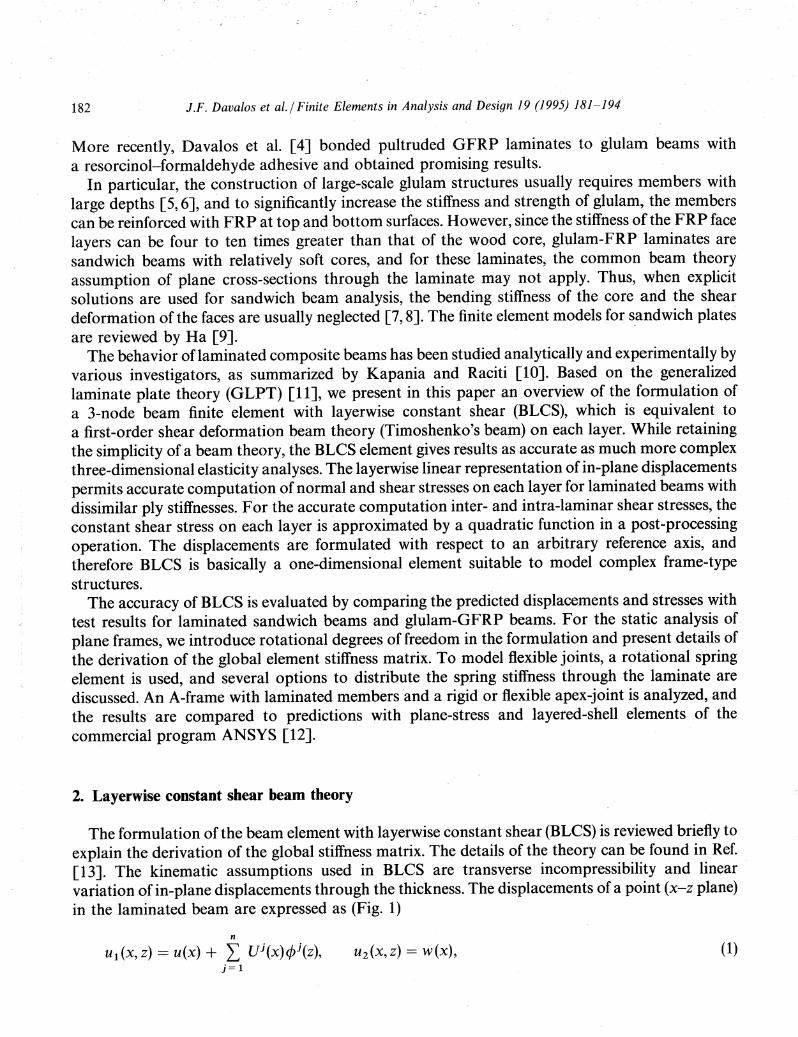
The formulation of the beam element with layerwise constant shear (BLCS) is reviewed briefly toexplain the derivation of the global stiffness matrix. The details of the theory can be found in Ref.[13]. The kinematic assumptions used in BLCS are transverse incompressibility and linearvariation of in-plane displacements through the thickness. The displacements of a point (x-z plane)in the laminated beam are expressed as (Fig. 1)
n
Ul (x, z) == u(x) + L Ui(x)¢i(z),i= 1
U2 (x, Z) == W(X), (1)
J.F. Davalos et al.I Finite Elements in Analysis and Design 19 (1995) 181-194
Defonned State
183
z
reference axis Initial State
* .../ .........•................P
w(x)u 2(x) = w(x)
x
Layer I
U(x) U(x,z
u I (x)
Fig. 1. Displacement components of a point p in the laminate.
where u and ware, respectively, the longitudinal and transverse displacements of a point ·on thereference axis of the laminate, and Ui(x) represent layerwise in-plane displacements approximatedby linear Lagrange interpolation functions 4Ji(z). To represent the state of stress in each cross-plylamina, the following approximations are used: (Jy = (Jxy = (Jyz = o. Using these approximationsand the transformed stress-strain relation of an orthotropic lamina under the assumption of planestress in the x-y plane, the constitutive relation of a lamina is derived. Using the laminaeconstitutive relations and integrating stresses through the thickness, the constitutive equation ofthe laminate is established. In the finite element formulation of BLCS, the strain-displacementrelation of an m-node element is defined as
where the superscripts 0 andj refer, respectively, to quantities at the reference axis and the laminaeinterfaces, and [BLJ and [ELJ are compatibility matrices expressed in terms of interpolationfunctions. Applying the principle of virtual work, the N-Iayer element model is obtained as follows:
or
{f} = [k] {d}, (2)
where b is the beam width, {F} includes transverse and axial force vectors applied at the referenceaxis, {F~} contains axial force vectors applied at the laminae interfaces, and the submatrices are
184
defined as
J.F. Davalos et aLI Finite Elements in Analysis and Design 19 (1995) 181-194
The number of degrees of freedom per element is (2 + N)m. In a post-processing operation, theconstant shear stress on each layer is converted into a parabolic shear stress distribution.
30 Formulation of the global stiffness matrix
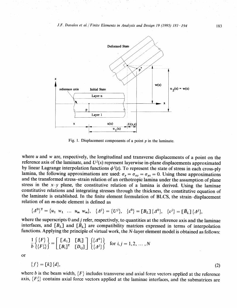
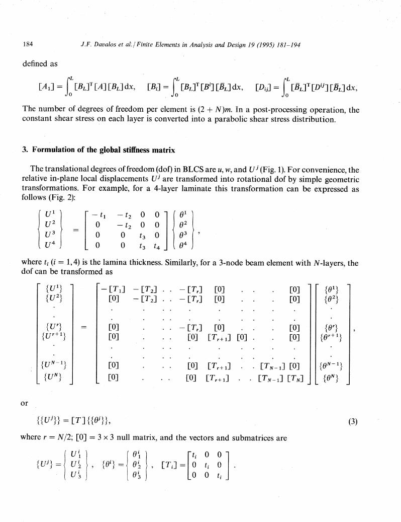
The translational degrees of freedom (dof) in BLCS are u, W, and V j (Fig. 1). For convenience, therelative in-plane local displacements vj are transformed into rotational dof by simple geometrictransformations. For example, for a 4-layer laminate this transformation can be expressed asfollows (Fig. 2):
VI - t1 - t2 0 0 01
U2 0 - t 2 0 0 02
U3 -0 0 0 f)3t3
U4 0 0 t 3 t4f)4
where ti (i = 1,4) is the lamina thickness. Similarly, for a 3-node beam element with N-Iayers, thedof can be transformed as
- [T 1J - [Tz][0] - [Tz]
[0][0]
[OJ[OJ
[0][Tr + 1] [0] .
[0][0]
[0][0]
or
[0]
[0]
[0] [Tr + 1]
[0] [Tr + 1]
. [TN-I] [0]
· [TN-I] [TN]
{{uj}} == [T] { { f)i} } ,
where r = N /2; [0] = 3 x 3 null matrix, and the vectors and submatrices are
(3)
J.F. Davalos et al.I Finite Elements in Analysis and Design 19 (1995) 181-194
Defonned cross section
185
layer 4
layer 3
layer 2
layer 1 8 1i•U 2_
1
Fig. 2. In-plane translational and rotational dof in a 4-layer laminate.
Local
reference axis
z
'----------------x
Global
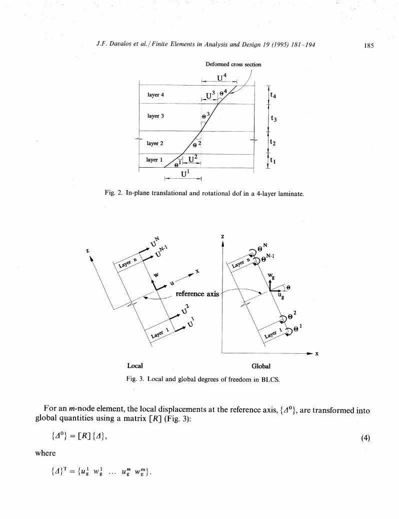
Fig. 3. Local and global degrees of freedom in BLCS.
For an m-node element, the local displacements at the reference axis, {jO}, are transformed intoglobal quantities using a matrix [R] (Fig. 3):
(4)
where
u~ w~}.

186 J.F. Davalos et al./Finite Elements in Analysis and Design 19 (1995) 181-194
For a 3-node beam element, [R] becomes
cosO sin 0 0 0 0 0- sin f) cosO 0 0 0 0
0 0 cos f) sinO 0 00 0 - sin f) cosO 0 00 0 0 0 cosO sin f)
0 O' 0 0 - sinO cosf)
where f) is the angle between local and global axes. Then, the local force and local displacementvectors can be transformed into global terms as follows:
{Q} = [A]T (f}, {d} = [A] {D},
where [A] is defined as
[[R] 0 ]o [T]
and the global force and displacement vectors are
(5)
{q}{q~}
{Q} =
{L1}{81
}, {D} =
Finally, consistent with matrix formulations, the global element model is expressed as
{Q} = [A]T [k] [A] {D} = [K] {D}, (6)
where the local element stiffness matrix [k] is given in Eq. (2), and the global element stiffnessmatrix [K] is written as
[[R]T [A 1] [R] [R]T [B i ] [T] ][T]T [Bi]T [R] [T] [D ij] [T] ·
In addition to the global element stiffness matrix, a rotational spring element is used to analyzeframes with flexible joints, as discussed next.
4. Connection modeling with spri~g elements
A rigid joint commonly assumed in structural analysis is seldom possible in sandwich beams,and a flexible joint can model the response more accurately. A rotational spring can simulatea flexible joint that transmits a moment proportional to the relative rotation of the spring.Following Holzer [14], the moment-rotation relation for a 2-dof spring element can be written

as
J.F. Davalos et al./ Finite Elements in Analysis and Design 19 (1995) 181-194 187
(7)
where y is spring stiffness (moment per unit radian), which represents the slope of the moment-rotation curve and can be found experimentally, as discussed in Ref. [15] for full-size tests ofbeam-to-column moment connections of glass-vinylester pultruded .sections. Expressed in matrixform, Eq. (7) becomes
{il} = Y [ 1 - IJ {81}..12 - 1 1 82
In the BLCS formulation of element-to-element connection with spring elements, the nodes atthe reference axis are connected, and the stiffness of the spring element is distributed through thelamin·ae above and below the reference axis. Since rotational dof are provided at the laminaeinterfaces through the laminate thickness (Fig. 3), except at the reference axis, several approachescan be used to distribute the spring stiffness through the laminate thickness. Considering that therelative rotation of a beam section is proportional to its bending stiffness, the stiffness of the springconnector can be distributed layerwise in proportion to the bending stiffness of each layer. Then,the spring stiffness corresponding to the kth layer of anN-layer laminate can be expressed as
E~ (ti/12 + zf tk ) (8)Yk = ~N . j 3 -2 Y,
L.Jj=IE x (t j /12 + Zj tj )
where Y is the joint stiffness and Zk is the distance from the beam neutral axis to the centroid of thekth layer. Another possibility is to distribute the joint stiffness either uniformly or selectivelythrough the laminate. This approach may be useful for sandwich beams with soft cores, for whichthe stiffness of the spring element can be distributed only to· the top and bottom face laminae. Weinvestigated several of these schemes and obtained similar results for various laminates. In thepresent study, the first method is used (Eq. (8)) for the analysis of an A-frame with flexible joints.
5. Numerical examples
The accuracy of the BLCS element is illustrated by analyzing the response of laminated beams andan A-frame with laminated sections and a rigid or flexible apex-joint. To evaluate the capabilities ofBLCS to predict member response, we use experimental results for glued-laminated timber(glulam) beams reinforced with GFRP and experimental/analytical results for sandwich beams.
5.1. M ember response
We present two examples to demonstrate the capability of the model to predict beam behavior.
1. Glulam-GFRP beamsDavalos et at [4] conducted two-point bending tests of simply supported glulam beams
reinforced with pultruded GFRP strips (Fig. 4). The material properties of the wood laminate given

188 J.F. Davalos et al./ Finite Elements in Analysis and Design 19 (1995) 181-194
in Table 1 are the averages of six wood layers. The longitudinal and shear moduli of the GFRP are19.7 and 3.80GPa, respectively, and the thickness is 9.4mm. The ratios shown in Table 2 areobtained by dividing the maximum displacements and tensile stresses of BLCS with thosemeasured experimentally. The results show that the BLCS predictions agree closely with theexperimental values.'
2. Sandwich beamsThe bending response of laminated sandwich beams is evaluated with ANSYS and BLCS. The
beams were tested under two-point loading by Kemmochi and Uemura [16], who used photoelasticity to measure the stress distribution. The beam configuration and modeling of one half of thebeam are given in Fig. 5. The material properties and load (p) are reported in Table 3 for two
13344N
3 @ 40.6 = 122 em
5.6 em 5.6 em,- -I ,- -I
Wood
VGFRP
-I without GFRP with GFRP
Section lay-up
Fig. 4. Configuration of glulam-GFRP beams.
Table 1Material properties of wood layers
Beam no. E avg (GPa) Gavg (GPa) tavg (mm)
1 15.12 0.7 19.392 14.52 0.70 19.393 14.47 0.68 19.44 13.71 0.73 19.09
Table 2Maximum displacement and stress ratios (BLCS/experimental)
Beam Without GFRP With GFRPno.
Displacement Stressa Displacement Stressb
1 0.933 0.929 0.943 0.9002 1.022 0.996 1.025 1.0623 0.947 0.960 1.001 1.0854 0.906 0.954 0.905 1.087
a Stresses are measured at the middle of the lower wood layer.b Stresses are measured at the bottom of the G FRP layer.

J.F. Davalos et al.I Finite Elements in Analysis and Design 19 (1995) 181-194 189
~\7 v
,.,4:~ ~
I'"
p
4 @ 55= 220 nuna:-I
face
core
face6.57 romI'" .. I
Section
4.72 rom
30.0 mm
4.72 rom
BLes8 elements with8 layers per element
v"--v~v
V/
..--v~~ ~v
vV
hV'--'v
ANSYS : 2-D plane stresselement(STIF 42)64 elements
dJ(;/ / / It! 7 / z1lJANSYS : Layered - shellelement(STIF 99)8 elements
Fig. 5. Sandwich beam configuration and modeling.
Table 3Material properties and loads
Case A Case B
Face' Core Face Core
E (MPa) 2440 521 2440 4.34G (MPa) 875 181 875 0.53p (N) 98 9.8
material/load cases. Using the commercial program ANSYS, the beams are analyzed by twoelements: (1) plane-stress, 4-node isoparametric element (STIF 42) and (2) Mindlin layered-shell,8-node element (STIF 99). Because of its favorable bending characteristics, an 8-node plane-stresselement (STIF 82) was initially used in the analysis, but similar results to' those given by the 4-nodeelement were obtained and, thereafter, the 4-node element .was chosen in this study. The midspanmaximum displacement and normal stress distribution are given in Table 4 and Fig. 6, respectively.The experimental displacements of the beams were not reported in Ref. [16]. For Case A, bothBLCS and ANSYS predict values quite close to those of Kemmochi and Uemura. For the soft-coreCase B, it is noticeable that the sign-change of normal stress within the face material cannot beaccurately predicted with the layered-shell element. In addition, and more sig.nificantly, theMindlin layered-shell element, which assumes first-order shear deformation through the crosssection, experiences "shear-locking" when the core material is soft. (The longitudinal and shearstiffness of the core for Case B are, respectively, 120 and 342 times lower than for Case A.) Asindicated in Table 4, the Mindlin layered-shell element predicts a very stiff response.

190 J.F. Davalos et al.I Finite Elements in Analysis and Design 19 (1995) 181-194
-2.0 -1.0 o
Case A
19.72 rom15.00
0.0
-15.00
-19.72 mm1.0 2.0 MPa -0.5 -0.25 0 0.25
CaseB
0.5 MPa
•o
Kemmochi & Uemura(experimental)BLCSANSYS (plane stress element)
ANSYS (layered-shell element)
Fig. 6. Normal stress distribution at midspan..
Table 4Comparison of maximum displacement (mm)
BLCS ANSYS
Plane stress Layered-shell
Case ACase B
0.350.76
0.350.74
0.310.04
5.2. Frame response
To evaluate the performance of the BLCS element in frame analysis, an A-frame with laminatedcro~s-sectionand loaded at the apex with concentrated loads is examined (see Fig. 7). Two materiallay-up configurations are used (Fig. 7 and Table 5): in Case 1 the material properties' varyprogressively through the depth, and in Case 2 the face material is much stiffer than the corematerial, and therefore Case 2 represents a soft-core sandwich member. The frame is modeled withBLCS using 16 elements with six layers per element; when modeling with ANSYS, we used 96plane-stress elements and 16 layered-shell elements. The frame is modeled for a rigid connectionand also a flexible connection at the apex. To simulate a flexible connection with BLCS the springelement described earlier (Eqs. (7) and (8» is used; similarly, a spring element (STIF 27) is used inconjunction with the layered-shell element of ANSYS. Since the plane-stress element in ANSYSdoes not have a rotational dof, a spring element cannot be used in this case, and therefore the

J.F. Davalos et al.j Finite Elements in Analysis and Design 19 (1995) 181-194 191
material nwnber/
ooסס2 N
~1
2000N f <l:25m-u 2 1A!,
w 3 42m
2 11 1
4m 4m13 em
I'" --I- "II- -I
Case 1 Case 2
0.5 em7.0 em
20 em
7.0 em0.5 em
Fig. 7. Frame configuration and cross-sections.
Table 5Material properties
Material no.
1234
E (MPa)
500015001100
110
G (MPa)
800500400
80
Table 6Displacements comparison (mm)
Case 1 Case 2
Rigid joint Flexible joint Rigid joint Flexible joint
BLCS PS LS BLCS LS BLCS PS LS BLCS LS
u 0.109 0.104 0.090 0.109 0.090 0.303 0.248 0.056 0.303 0.056w 3.938 3.970 3.559 4.357 3.584 6.958 7.19 2.205 12.14 2.223
PS = plane stress; LS = layered shell.
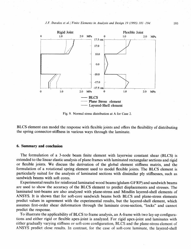
ANSYS plane-stress element is used only for the rigid-jointed Cases 1 and 2. The spring stiffnessused for the analysis is 105 N m/rad. The displacements of the apex of the frame are given inTable 6, and the normal stress distributions at point A near the apex (Fig. 7) are shown in Fig. 8 forCase 1 and in Fig. 9 for Case 2.
For Case 1 with rigid joint, the plane-stress (PS) element and BLCS predict basically the samevalues for deflections u and w (see Fig. 7 and Table 6) and normal stress (Fig. 8), whereas the

192 J.F. DavaLos et al.I Finite Elements in Analysis and Design 19 (1995) 181-194
Rigid Joint Flexible Joint0 1.0 2.0 MPa 0 1.0 2.0 MPa
17.5 em
17.0
10.0
0.0
-10.0
-17.0
-17.5 em-----r-- --r- I
0 1.0 2.0 MPa 0 1.0 2.0 MPa
-BLCS................... Plane Stress element.,~,.,"..".""".".",. Layered-Shell element
Fig. 8. Normal stress distribution at A for Case 1.
layered-shell element is slightly stiffer than the BLCS and PS elements, but the normal stressdistribution at A coincides with BLCS and ·PS (Fig. 8). For Case 1 with flexible joint, the maximumvertical d~flection given by the layered-shell element is 17% below the value given by BLCS(Table 6), and the distribution of normal stress (Fig. 8) with the layered-shell element is approximately constant on each layer consistent with the assumption of plane sections through thecross-section; in contrast, the layerwise formulation with BLCS can model the linear deformationon each layer more accurately.
For Case 2 with rigidjoint, the deflection predictions with BLeS and PS are close to each other,but the layered-shell element locks and cannot predict the response of the frame (Table 6). Also,similar stress distribution are predicted with BLCS and PS (Fig. 9), but the stresses predicted withthe layered-shell element are significantly different for the outer layers. For Case 2 witp. flexiblejoint, th.e layered-shell element exhibits an extremely stiff behavior and cannot predict themaximum deflection of the frame (Table 6), although the stress predictions follow.the general tre·ndof the BLCS stress distribution (Fig. 9).
The results obtained for Case B.ofthe sandwich beam (see member-response study, Table 3) andCase 2 of the A-frame indicate that for soft-core laminates the assumption of plane sectionsthrough the cross-section can result in shear-locking and inaccurate stress predictions. It is shownthat the BLCS element can accurately predict displacements and stresses for frames with soft-corelaminated members, as verified with the plane-stress element of ANSYS.
Although the number of dof with BLCS is approximately the same as that of the plane-stresselement, the BLCS mesh-definition is relatively simple and similar to that of a one-dimensionalbeam element. When flexible joints are included in the analysis of soft-core laminates, theshear-locking phenomenon with the Mindlin layered-shell element is exacerbated. Once again, the
J.F. Davalos et al.I Finite Elements in Analysis and Design 19 (1995) 181-194 193
10.0
- 17.0
0.0
-10.0
Rigid Joint Flexible Joint1.0 2.0 MPa 0 1.0 2.0 MPa
f--------l---_---L-__._..L.--;r L- 17.5 em I-:--_--l-.._-..L...".---.,----L.--- .l..__ .. _
o
2.0 MPa1.0
- -17.0
-17.5 emI-:-----r------r'-~-.,.-----.------l
2.0 MPa 01.0o
-BLCS"................. Plane Stress element""""..."""-.,,,,, Layered-Shell element
Fig. 9. Normal stress distribution at A for Case 2.
BLCS element can model the response with flexible joints and offers the flexibility of distributingthe spring connector-stiffness in various ways through the laminate.
6. Summary and conclusion
The formulation of a 3-node beam finite element with layerwise constant shear .(BLCS) isextended to the linear elastic analysis of plane frames with laminated rectangular sections and rigidor flexible joints. We discuss the derivation of the global element stiffness matrix, and theformulation of a rotational spring element used to model flexible joints. The BLCS element isparticularly suited for the analysis of laminated sections with dissimilar ply stiffnesses, such assandwich beams with soft cores.
Experimental results for reinforced laminated wood beams (glulam-GFRP) and sandwich beamsare used to show the accuracy of the BLCS element to predict displacements and stresses. Thelaminated test-beams are also analyzed with plane-stress and Mindlin layered-shell elements .ofANSYS. It is shown that for soft-core sandwich beams both BLCS and plane-stress elementspredict values in agreement with the experimental results, but the layered-shell element, whichassumes first-order shear deformation through the laminate cross-section, "locks" and cannotpredict the response.
To illustrate the applicability of BLCS to frame analysis, an A-frame with two lay-up configurations and either rigid or flexible apex-joint is analyzed. For rigid apex-joint and laminates witheither gradually varying stiffness or soft-core configuration, BLCS and the plane-stress element ofANSYS predict close results. In contrast, for the case of soft-core laminate, the layered-shell
194 J.F. Davalos et al.I Finite Elements in Analysis and Design 19 (1995) 181-194
element of ANSYS predicts inaccurate results for rigid and flexible apex-joints. Because of thelayerwise linear formulation, BLCS can efficiently model plane frames with soft-core laminates andflexible joints. The BLCS formulation offers the flexibility of distributing the connector springstiffness either selectively or uniformly through the cross-section laminae. In this paper, an.expression is provided to distribute the spring stiffness in proportion to the bending stiffness ofeach layer. .
References
[1] H.Saadtmanesh and M.R. Ehsani, "RC beams strengthened with GFRP: experimental study",J. Struct. Eng. 117,pp. 3417-3433, 1991.
[2] T.C..Triantafillou and N. Deskovic, "Prestressed FRP sheets as external reinforcem.ent of wood members", J.Struct. Eng. 118, pp. 1270-1284,1992.
[3] N. Plevris and T. Triantafillou, "FRP-reinforced wood as structural material", J. Mater. Civ. Eng. 4, pp. 300-317,1992.
[4] J.F. Davalos, H.A. Salim and U. Munipalle, "Glulam-GFRP composite beams for stress-laminated T-systembridges", Proc. 1st Int. Conf. ofAdvanced Composite Materials in Bridges and Structures, CSCE-CGC, Sherbrooke(Quebec), Canada, pp. 455-464, 1992.
[5] S.M. Holzer, J.F. Davalos and C.Y. Huang, "A review of finite element stability investigation of spatial woodstructures", Bull. Int. Assoc. Shell Spatial Struct. 31, pp. 161-171, 1991.
[6] J.F. Davalos, Y. Kim and S.S. Somnath, "Analysis of glulam-FRP beams by a layer-wise formulation", Proc.IASS-ASCE Int. Symp. '94, Atlanta, Georgia, pp. 67-75,1994.
[7] R.A. DiTaranto, "Static analysis of a laminated beam", J. Eng. Ind. 95, pp. 755-761, 1973.·[8] K.H. Ha and L.S. Salvador, "Stiffness matrices for exact analysis of sandwich beam systems", Proc. 2nd Int. Conf. on
Sandwich Construction, 1, pp. 67-89, 1992.[9] K.H. Ha, "Finite element analysis of sandwich plates: an overview", Comput. Struct. 37, pp. 397-403, 1990.
[10] R.K. Kapania and S. Raciti, "Recent advances in analysis of laminated beams and plates. Part 1: shear effect andbuckling", AIAA J. 27, pp. 923-934, 1989. .
[11] J.N. Reddy, "A generalization of two-dimensional theories of laminated composite plates", Commun. Appl. Numer.Methods 3, pp. 1,73-180, 1987.
[12] ANSYS User's Manual, Swanson Analysis System Inc., Houston, PA, 1989.[13] Y. Kim, J.F. Davalos and E.J. Barbero, "Composite beam element with layerwise plane sections", J. Eng. Mech.
ASCE 120 (5), pp. 1160-1166, 1994.[14] S.M. Holzer, Computer Analysis of Structures, Elsevier, New York, 1985.[15] L.C. Bank and A.S. Mosallam" "Performance ofpultruded FRP beam-to-column connections", Proc. ASCE Struct.
Congr. '91, pp. 389-392, 1991.[16] K. Kemmochi and M. Uemura, "Measurement of stress distribution in sandwich beams under four-point bending",
Exp. Mech. 20, pp. 80-86, 1980.