FINITE ELEMENT STUDIES IN THE TWO-WAY OUT-OF …km6e/Papers/6-NCEE.pdf · plane response of...
12
1 FINITE ELEMENT STUDIES IN THE TWO-WAY OUT-OF-PLANE FAILURE OF UNREINFORCED MASONRY Kirk Martini 1 Abstract The paper describes finite element studies of an unreinforced masonry wall panel sup- ported on the bottom and sides, and unsupported on the top, with no vertical surcharge. The analysis is based on a discrete cracking model, termed a block-interface model, using elastic volume elements to model masonry material, and surface contact elements to model mortar joints. After discussing the effects of mesh configuration, the behavior of the model is interpreted in terms of yield line theory, and a modified version of yield line theory is presented, using simplifying assumptions to account for the observed behavior of the finite element model. Comparison of the finite element results with the yield line results shows that the yield line analysis predicts a somewhat lower failure load, but reasonably approximates the pattern of failure. The paper concludes that the computationally intensive block-interface model is primarily useful in developing deeper knowledge of the two-way behavior of unreinforced walls in order to develop more practical methods such as the modified yield line method presented in the paper. 1 Assistant Professor of Architecture and Civil Engineering, Department of Architecture, Univer- sity of Virginia, Charlottesville VA 22903
-
Upload
vuongtuong -
Category
Documents
-
view
213 -
download
0
Transcript of FINITE ELEMENT STUDIES IN THE TWO-WAY OUT-OF …km6e/Papers/6-NCEE.pdf · plane response of...

1
FINITE ELEMENT STUDIES IN THE TWO-WAY OUT-OF-PLANEFAILURE OF UNREINFORCED MASONRY
Kirk Martini1
Abstract
The paper describes finite element studies of an unreinforced masonry wall panel sup-ported on the bottom and sides, and unsupported on the top, with no vertical surcharge.The analysis is based on a discrete cracking model, termed a block-interface model,using elastic volume elements to model masonry material, and surface contact elementsto model mortar joints. After discussing the effects of mesh configuration, the behaviorof the model is interpreted in terms of yield line theory, and a modified version of yieldline theory is presented, using simplifying assumptions to account for the observedbehavior of the finite element model. Comparison of the finite element results with theyield line results shows that the yield line analysis predicts a somewhat lower failureload, but reasonably approximates the pattern of failure. The paper concludes that thecomputationally intensive block-interface model is primarily useful in developing deeperknowledge of the two-way behavior of unreinforced walls in order to develop morepractical methods such as the modified yield line method presented in the paper.
1 Assistant Professor of Architecture and Civil Engineering, Department of Architecture, Univer-sity of Virginia, Charlottesville VA 22903
2
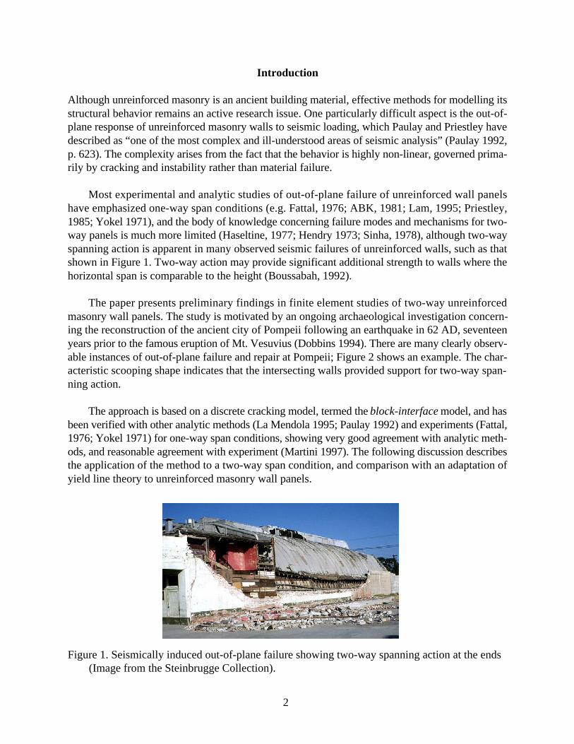
Figure 1. Seismically induced out-of-plane failure showing two-way spanning action at the ends(Image from the Steinbrugge Collection).
Introduction
Although unreinforced masonry is an ancient building material, effective methods for modelling itsstructural behavior remains an active research issue. One particularly difficult aspect is the out-of-plane response of unreinforced masonry walls to seismic loading, which Paulay and Priestley havedescribed as “one of the most complex and ill-understood areas of seismic analysis” (Paulay 1992,p. 623). The complexity arises from the fact that the behavior is highly non-linear, governed prima-rily by cracking and instability rather than material failure.
Most experimental and analytic studies of out-of-plane failure of unreinforced wall panelshave emphasized one-way span conditions (e.g. Fattal, 1976; ABK, 1981; Lam, 1995; Priestley,1985; Yokel 1971), and the body of knowledge concerning failure modes and mechanisms for two-way panels is much more limited (Haseltine, 1977; Hendry 1973; Sinha, 1978), although two-wayspanning action is apparent in many observed seismic failures of unreinforced walls, such as thatshown in Figure 1. Two-way action may provide significant additional strength to walls where thehorizontal span is comparable to the height (Boussabah, 1992).
The paper presents preliminary findings in finite element studies of two-way unreinforcedmasonry wall panels. The study is motivated by an ongoing archaeological investigation concern-ing the reconstruction of the ancient city of Pompeii following an earthquake in 62 AD, seventeenyears prior to the famous eruption of Mt. Vesuvius (Dobbins 1994). There are many clearly observ-able instances of out-of-plane failure and repair at Pompeii; Figure 2 shows an example. The char-acteristic scooping shape indicates that the intersecting walls provided support for two-way span-ning action.
The approach is based on a discrete cracking model, termed the block-interface model, and hasbeen verified with other analytic methods (La Mendola 1995; Paulay 1992) and experiments (Fattal,1976; Yokel 1971) for one-way span conditions, showing very good agreement with analytic meth-ods, and reasonable agreement with experiment (Martini 1997). The following discussion describesthe application of the method to a two-way span condition, and comparison with an adaptation ofyield line theory to unreinforced masonry wall panels.

3
Figure 2. Evidence of two-way out-of-plane failure in a masonry wall in the ancient city ofPompeii.
Figure 3. Organization of the finite element mesh for the block-interface model.
Studies of Two-way Behavior
The Study Panel
The study focuses on the behavior of a two-way panel, simply supported on the side edges, sittingon a rigid base at the bottom, and unsupported at the top. The properties of the panel are as follows:length = 12.2 m (40 ft); height = 6.1 m (20 ft) thickness = 0.51 m (20 in); E = 0.62 GPa (90 ksi);weight density = 15.7kN/m3 (100 pcf). The panel has no compressive surcharge, but the analysisaccounts for the self weight. These dimensions and properties are unusual for modern structuresbut are similar to many ancient masonry walls at Pompeii.
The block-interface approach uses 8-node elastic volume elements to model masonry mate-rial, and 8-node surface-contact elements to model mortar joints. All analyses use a coefficient offriction of 1.0 for the interface element although this value has not been verified by experiment.Figure 3 shows a diagram of a typical finite element mesh, described using the following terms:

4
Figure 4. Load-displacement curves for three different mesh configurations of the study panel.
• Course: A course corresponds to a horizontal row of masonry units, separated from adjacentcourses by arrays of 8-node surface-contact elements at coincident nodes.
• Layer: A layer is a horizontal subdivision of a course into continuous 8-node elastic finiteelements.
• Lamination: A lamination is a vertical subdivision of a course into continuous finite ele-ments.
Mesh Configuration and Behavior
The panel was tested with a variety of mesh configurations to assess the fineness of the meshrequired to achieve satisfactory results. Figure 4 shows load-displacement curves for three differ-ent mesh configurations; each mesh uses 10 courses composed of either 10 full blocks or 9 fullblocks and two half blocks at the ends, each with four laminations. The three curves compareresults for models with one, two, and three layers. The models were subjected to a uniform pressureon one face of the wall, increased using displacement control at the center of the top of the walluntil it became impossible to find an equilibrium state using a load increment larger than a speci-fied minimum value.
All the curves have a similar two-branch form: an initial high-stiffness branch, followed by asecond low-stiffness branch. Comparing the curves reveals that the three models are nearly identi-cal on the high-stiffness branch, but vary along the low-stiffness branch, with the finer meshesshowing greater strength and stiffness. This result is contrary to that found with one-way panels,where it was found that finer meshes tended to show less stiffness along both legs of the load-displacement curve (Martini, 1997). The fact that the difference occurs only on the low-stiffnessbranch indicates that the mechanism of load transfer in that region is sensitive to mesh configura-tion, while the mechanism on the other branch is not. To understand the differences of the loadtransfer mechanisms in the two regions, it is useful to examine the distribution of reaction forcesfor each.

5
Figure 5. Patterns of reaction force vectors at different stages of loading, corresponding to pointsA and B of Figure 4.
Point A Point B
Figure 5 shows the distribution of reaction-force vectors corresponding to the points marked Aand B on the curve of Figure 4. For point A in the high stiffness region, the horizontal reactionforces along the vertical edge supports are very small compared to the reactions at the base. Thebase shear for the wall is resisted by the horizontal component of the base reaction forces, and theoverturning moment is resisted by the eccentric vertical reaction as the base of the wall rotates.Note that the alternating large and small reaction forces at the base are the result of the runningbond organization of the mesh, the larger forces occur at the head joint where two blocks meet.
At point B the pattern is quite different. The horizontal reaction forces form a series of largecouples along the vertical edges. Figure 6 compares the distribution of vertical forces along onevertical edge for the two stages of loading. For point A, the horizontal reactions at the two verticaledges account for 14 percent of the base shear and 37 percent of the overturning moment. At pointB, these reactions account for less than 0.5 percent of the base shear and 64 percent of the overturn-ing moment. The larger couples occur at alternating courses, these are the courses that terminate ina full length block.
Figure 6. Distribution of horizontal reaction forces along a vertical edge, corresponding to pointsA and B on Figure 4.
0.0
0.6
1.2
1.8
2.4
3.0
3.7
4.3
4.9
5.5
6.1
-50 -40 -30 -20 -10 0 10 20 30 40 50
Horizontal reaction at vertical edge (kN)
Cou
rses
abo
ve b
ase
Point APoint B
1
2
3
4
5
6
7
8
9
10
6
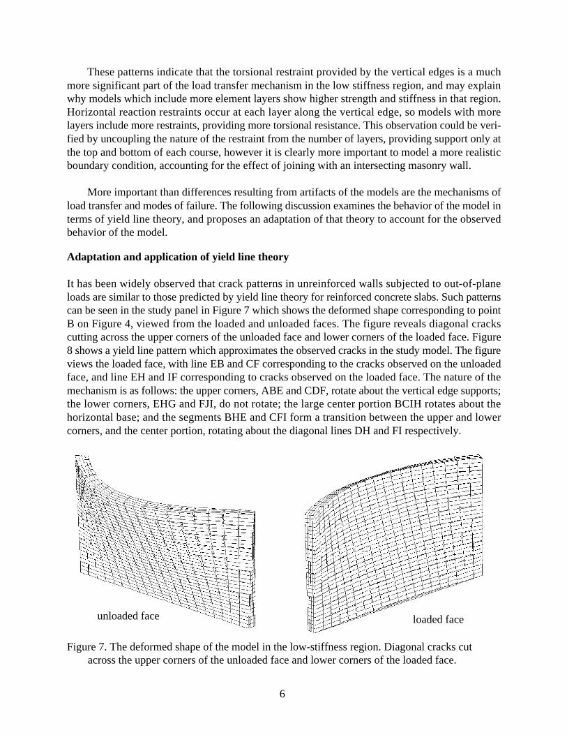
Figure 7. The deformed shape of the model in the low-stiffness region. Diagonal cracks cutacross the upper corners of the unloaded face and lower corners of the loaded face.
unloaded face loaded face
These patterns indicate that the torsional restraint provided by the vertical edges is a muchmore significant part of the load transfer mechanism in the low stiffness region, and may explainwhy models which include more element layers show higher strength and stiffness in that region.Horizontal reaction restraints occur at each layer along the vertical edge, so models with morelayers include more restraints, providing more torsional resistance. This observation could be veri-fied by uncoupling the nature of the restraint from the number of layers, providing support only atthe top and bottom of each course, however it is clearly more important to model a more realisticboundary condition, accounting for the effect of joining with an intersecting masonry wall.
More important than differences resulting from artifacts of the models are the mechanisms ofload transfer and modes of failure. The following discussion examines the behavior of the model interms of yield line theory, and proposes an adaptation of that theory to account for the observedbehavior of the model.
Adaptation and application of yield line theory
It has been widely observed that crack patterns in unreinforced walls subjected to out-of-planeloads are similar to those predicted by yield line theory for reinforced concrete slabs. Such patternscan be seen in the study panel in Figure 7 which shows the deformed shape corresponding to pointB on Figure 4, viewed from the loaded and unloaded faces. The figure reveals diagonal crackscutting across the upper corners of the unloaded face and lower corners of the loaded face. Figure8 shows a yield line pattern which approximates the observed cracks in the study model. The figureviews the loaded face, with line EB and CF corresponding to the cracks observed on the unloadedface, and line EH and IF corresponding to cracks observed on the loaded face. The nature of themechanism is as follows: the upper corners, ABE and CDF, rotate about the vertical edge supports;the lower corners, EHG and FJI, do not rotate; the large center portion BCIH rotates about thehorizontal base; and the segments BHE and CFI form a transition between the upper and lowercorners, and the center portion, rotating about the diagonal lines DH and FI respectively.

7
Figure 8. Yield line pattern approximating crack patterns observed in the finite element model,viewed from the loaded face.
Although crack patterns are often similar to yield line patterns, several researchers have pointedout that there is no theoretical basis for applying yield line theory to an unreinforced wall, since thebending behavior is brittle (Hendry, 1973; Drysdale, 1994 p. 304; Sinha 1978); while this is cer-tainly true when the ultimate moment capacity is based on the modulus of rupture, it is possible toadapt yield line theory to unreinforced masonry walls by considering the post-cracking mecha-nisms of moment transfer for both vertical and horizontal directions. The following discussiondiscusses this adaptation, and then applies it to the study panel.
Vertical Moment Resistance
An unreinforced masonry bending member under compressive prestress exhibits a non-linear mo-ment-curvature relationship that exhibits significant loss of stiffness after cracking. (Paulay, 1992p. 635). The moment-curvature relationship is not ductile, since the relationship is elastic, but it isnonlinear and can be suitable for the application of yield line theory. since post-cracking displace-ments of a panel will result primarily from large rotations at the flexible cracks. To apply yield linetheory, it is necessary to identify the equivalent of a plastic moment. For a horizontal crack, theupper bound is simply the overturning resisting moment due to vertical loads, as follows (for sim-plicity, the expression omits the effect of a vertical surcharge, which can easily be incorporated):
m py =ρt2
2y (1)
where:mpy = ultimate vertical moment per horizontal lengthρ = weight densityt = wall thicknessy = vertical distance from top of wall to crack
Horizontal Moment Resistance
The transfer mechanism for horizontal moments is much less clear than for vertical moments. It iswell known that the modulus of rupture for horizontal moments in running-bond masonry is typi-

8
Figure 9. Plan view of horizontal moment transfer. The method assumes that the moment istransferred through friction contact with blocks above and below.
Figure 10. Free body diagram of a block subjected to horizontal moment. The method assumesthe moment is resisted by a friction couple.
cally three to five times greater than that for vertical moments (Sinha 1978, Hendry 1973), becauseof the interlocking of the blocks. Considering post-cracking behavior, it appears that moment trans-fer takes place through friction between horizontal surfaces at the bed joints between courses. Thefollowing discussion presents a very simple and approximate model for accounting for such afriction-based mechanism.
Figure 9 shows a plan view of two adjacent blocks, subjected to horizontal bending moments.Neglecting any tension strength of the head joint between the blocks, the moment must be trans-ferred via the blocks directly above and below through friction contact. Figure 10 shows a freebody diagram of a single block, with the applied moment balanced by a couple generated by fric-tion forces as the block rotates. The free body diagram makes several simplifying assumptions.First, the nature of the friction resistance to rotation will depend on the size and shape of the contactarea, however the area may vary depending on the state of cracking due to vertical moment; ifvertical moments have opened a large crack, then the contact area will be smaller and have lessrotational resistance. The current method assumes that there is horizontal cracking, and the depth ofthe contact area is limited to a small portion of the thickness of the wall. The method also assumesthat the relative rotation between the contact area occurs at the center of the area, and the resultingforces are based on Coulomb friction.
With those assumptions, the friction couple can be reduced to two forces acting at half thewidth of the contact area, i.e. one fourth the length of a block. Each force has a magnitude equal tothe friction coefficient times the vertical load corresponding to a one-quarter block width, as fol-lows:

9
F = µρtLb
4y (2)
where:F = force due to frictionµ = friction coefficientLb = length of a block
Thus it follows that the horizontal moment capacity per unit length along the vertical is equal to thefriction force times the moment arm, divided by the height of a masonry course, as follows:
m px = µρtLb
2( )16H c
y (3)
where:mpx = ultimate horizontal moment per vertical lengthHc = height of a masonry course
Yield Line Analysis
Applying yield line analysis to the panel with the moment capacities described above requiresaccounting for the variation of the moment capacity with position in the wall; for both horizontaland vertical moments, the capacity increases with increasing vertical prestress toward the bottomof the wall. For the case of constant moment, the total internal work, WI, for a panel may calculatedby summing the x and y components of work at each yield line, as shown in the following equation,using notation described in Figure 11 (Park, 1980 p. 284)
WI = mpxy0( )θx +∑ mpyx0( )θy∑ (4)
Figure 11. Calculation of internal work at an inclined yield line with constant moment capacityin each direction. (after Park 1980)

10
Figure 12. Calculation of internal work at an inclined yield line with varying moment capacity ineach direction.
Figure 13. Variation of failure load relative to the coefficient α for the mechanism shown infigure 9, using the modified yield line method.
To account for variation in moment capacity with position, this expression must be modified so thatthe moment capacity in each direction is integrated over the projected length of the yield line, asfollows (Figure 12):
WI = mpx
y1
y 2
∫ y( )dy
θx +∑ mpy
x1
x2
∫ y( )dx
θy∑ (5)
Using this modified formulation, yield line analysis was applied to the test panel, using the patternshown in Figure 8 and solving for the variable dimension coefficient α to achieve a minimumfailure load. Figure 13 shows a graph of the failure load as a function of α. The minimum load isslightly less than 1.5 kN, when α = 0.35, although α could reasonably take any value in the rangeof 0.3 to 0.4, since the variation is small. The meaning and implications of this result are discussedin the summary and conclusions.

11
Summary And Conclusions
Comparing the finite element results with the yield line analysis reveals important aspects of both.First, the yield line method predicts a failure load of 1.5 kPa, somewhat lower than the finite ele-ment analyses which predict in the range of 1.6 to 1.7 kPa. The α value of 0.35 predicted by theyield line analysis corresponds well with the crack patterns observed in the finite element model,where the diagonal yield lines in the upper corners extend below mid height. The comparisonindicates promise for a modified yield line approach to produce reasonable predictions of bothfailure loads and failure patterns in unreinforced masonry walls, although there are several aspectsrequiring additional refinement, particularly the mechanisms of horizontal moment transfer andappropriate values for the coefficient of friction. Although there is reasonable agreement with thetwo methods, both must be compared with experiments to more fully understand their limitations.
Although the block-interface approach to finite element modeling provides useful insights, itis computationally intensive. The static analysis of the 4 lamination, three-layer model presented inthis paper required 19 hours of CPU time on an RS/6000 model 390 using the ABAQUS analysispackage, including 1138 complete solutions of the stiffness equations for a model with 4,340 ele-ments and 6,250 nodes. The utility of the method lies in developing a deeper understanding of themechanics of unreinforced walls, and in developing more practical and approximate methods, suchas the modified yield line approach. This knowledge will help in interpreting patterns of damage inancient and modern masonry structures, and in developing renovation strategies that account forthe strengthening effect of two-way spanning action.
Acknowledgments
This work has been conducted as part of the Pompeii Forum Project, directed by John J. Dobbins,with support from the University of Virginia’s School of Architecture Dean’s Forum, the Center forAdvanced Studies, and the National Endowment for the Humanities. This support is gratefullyacknowledged.
References
ABK: A Joint Venture Methodology for Mitigation of Seismic Hazards in Existing UnreinforcedMasonry Buildings: Wall Testing, Out-of Plane, ABK-TR-04, El Segundo, CA, 1981.
Boussabah, L. and M. Bruneau “Review of the Seismic Performance of Unreinforced MasonryWalls” Proc. of the 10th World Conf on Eq. Eng., 1992, 4537-4540.
Dobbins, J.J. “Problems of Chronology, Decoration, and Urban Design in the Forum at Pompeii”American Journal of Archaeology 98, no. 4 (October 1994): 629-694.
Drysdale, R.G., A. Hamid and L.R. Baker, Masonry Structures: Behavior and Design, EnglewoodCliffs: Prentice Hall, 1994.

12
Fattal, S.G. and L. E. Cattaneo, Structural Performance of Masonry Walls Under Compression andFlexure National Bureau of Standards, Building Science Series, no. 73, 1976.
Haseltine, B.A, H.W.H West, J.N. Tutt “Design of Walls to Resist Lateral Loads” The StructuralEngineer 55, no. 10, (1977), 422-430.
Hendry, A.W. “The Lateral Strength of Unreinforced Brickwork,” The Structural Engineer 51, no.2, (1973): 43-50.
HKS: Hibbitt, Karlsson & Sorensen, Inc. ABAQUS, Pawtucket, Rhode Island: http://www.abaqus.com/, 1997.
Lam, N.T.K., J.L. Wilson, G.L Hutchinson “The Seismic Resistance of Unreinforced MasonryCantilever Walls in Low Seismicity Areas” Bulletin of the New Zealand National Societyfor Earthquake Engineering 28 no. 3 (1995): 179-195.
La Mendola, L.L, M. Papia, G. Zingone “Stability of Masonry Walls Subjected to Seismic Trans-verse Forces” Journal of Structural Engineering 121, no. 11 (1995), 1581-1587.
Lotfi, H.R. and P.B. Shing “Interface Model Applied to Fracture of Masonry Structures” Journal ofStructural Engineering 120, no. 1 (1994): 63-80.
Martini, K. “Finite Element Studies in the Out-of-Plane Failure of Unreinforced Masonry” Pro-ceedings of the International Conference on Computing in Civil and Building Engineering,vol. 1, C.K. Choi, ed., Korea, 1997.
Park, R. and W.L. Gamble Reinforced Concrete Slabs J. Wiley, 1980.
Paulay, T. and M.J.N Priestley Seismic Design of Reinforced Concrete and Masonry Buildings, J.Wiley, 1992.
Priestley, M.J.N. “Seismic Behviour of Unreinforced Masonry Walls,” Bulletin of the New ZealandNational Society for Earthquake Engineering 18, no. 2, (June 1985): 191-205.
Rots, J.G. “Numerical simulation of cracking in structural masonry” Heron, 36, no. 2 (1991) 49-63.
Sinha, B.P. “A Simplified Ultimate Load Analysis of Laterally Loaded Model Orthotropic Brick-work Panels of Low Tensile Strength” The Structural Engineer 56B, no. 4. (Dec 1978): 81-84.
Yokel, F.Y., R.G. Mathey, R.D. Dikkers, Strength of Masonry Walls Under Compressive and Trans-verse Loads, National Bureau of Standards, Building Science Series, no. 34, 1971.