
Machine tools, Lathe, conventional lathe, CNC lathe, slant ...

Finite Element Structural Analysis of CNC Lathe
Basava Raju Pondhe
Associate Professor, Don Bosco Institute of Technology, Bangalore, India E-Mail : [email protected]
Abstract—The Computer Numerical Controlled (CNC) Precision Chucker is a machine tool (lathe) indigenously designed and manufactured by HMT machine tools ltd. widely used in precision manufacturing Indian industries. This machine enables machine finishing to higher level which replaces grinding machine usage in some applications. The rigidity of the machine tool is very important aspect in determining the precision and surface finish accurate representation of individual components I parts of the whole machine tool is very essential i n predicting the behavior of the entire machine tool when it is subjected to the actual working condition. The joints like spindle-bearing, linear motion guideway-LM bearing is also another area of interest since these joints influence the rigidity of the entire machine tool. The finite element method is chosen for the modellingbecauseof its flexibility in reasonably accurate modeling of various parts of the machine tool[l]. SESAM [2], finite element analysis software, opted for the modelling of the machine tool since it has super-element technique to model the individual components of the machine tool separately. The machine tool consists of several components and each component has varying size of cross-sections. Hence line (beam), surface (shell) and solid (brick) finite elements are used to get reasonably accurate model of the whole machine tool. Though these elements have different degrees of freedom, coupling of these elements are properly considered at element interfaces by using shell-solid and beam-solid connectivity. several components are modelled separately as two sub-assemblies; the stationary equivalent cutting loads are applied on the machine tool spindle and reactive forces on the tool post; the deformation results. major components of the entire machine tool with worst cutting load conditions are analyzed., the machine tool was re-designed to increase the rigidity and to reduce the weight of the machine tool. Finally, the dynamic behavior of the machine tool is considered. By analyzing the defection of the structure, better rigidity of the machine for facing, turning (general cutting) and parting off operations from rear has been observed. The result shows the increase in the rigidity of the machine for these operations from rear as compared to front. From this one can conclude that machining from rear side is always better based on the rigidity.
I. INTRODUCTION
The Computer Numerical Controlled (CNC) Precision Chucker is a machine tool (lathe) widely used in precision manufacturing Indian industries. This machine enables machine finishing to higher level which replaces grinding machine usage in someapplications. The rigidity of the machine tool is very important aspect in determining the precision and surface finish resulted from-the machining operation. Many studies are available for the individual components of the machine tool with reasonably accurate modelling; in some studies, very coarse modelling is used to study the behavior of the entire machine tool. On the other hand, Grenze ID: 02.ICCTEST.2017.1.81 © Grenze Scientific Society, 2017
Proc. of Int. Conf. on Current Trends in Eng., Science and Technology, ICCTEST
484
reasonably accurate representation of individual components I parts of the whole machine tool is very essential in predicting the behavior of the entire machine tool when it is subjected to the actual working condition. The joints like spindle-bearing, linear motion guideway-LM bearing is also another area of interest since these joints influence the rigidity of the entire machine tool. The finite element method is chosen for the modelling because of its flexibility in reasonably accurate modeling of various parts of the machine tool[l]. SESAM [2], finite element analysis software, opted for the modelling of the machine tool since it has super-element technique to model the individual components of the machine tool separately.
II. DESCRIPTION OF MACHINE TOOL COMPONENTS
The machine tool consists of several major structural components like cabinet base, bed, intermediate block and headstock with spindle, Z-slide with linear motion (LM) guideways, X- slide with linear motion (LM) guideways, tool-platen and tool-post. The whole structure is mounted over four vibration pads. There are some non-structural components like, motor drives, motion feedback mechanismsandcontrollers,electroniccontrol panels, etc.
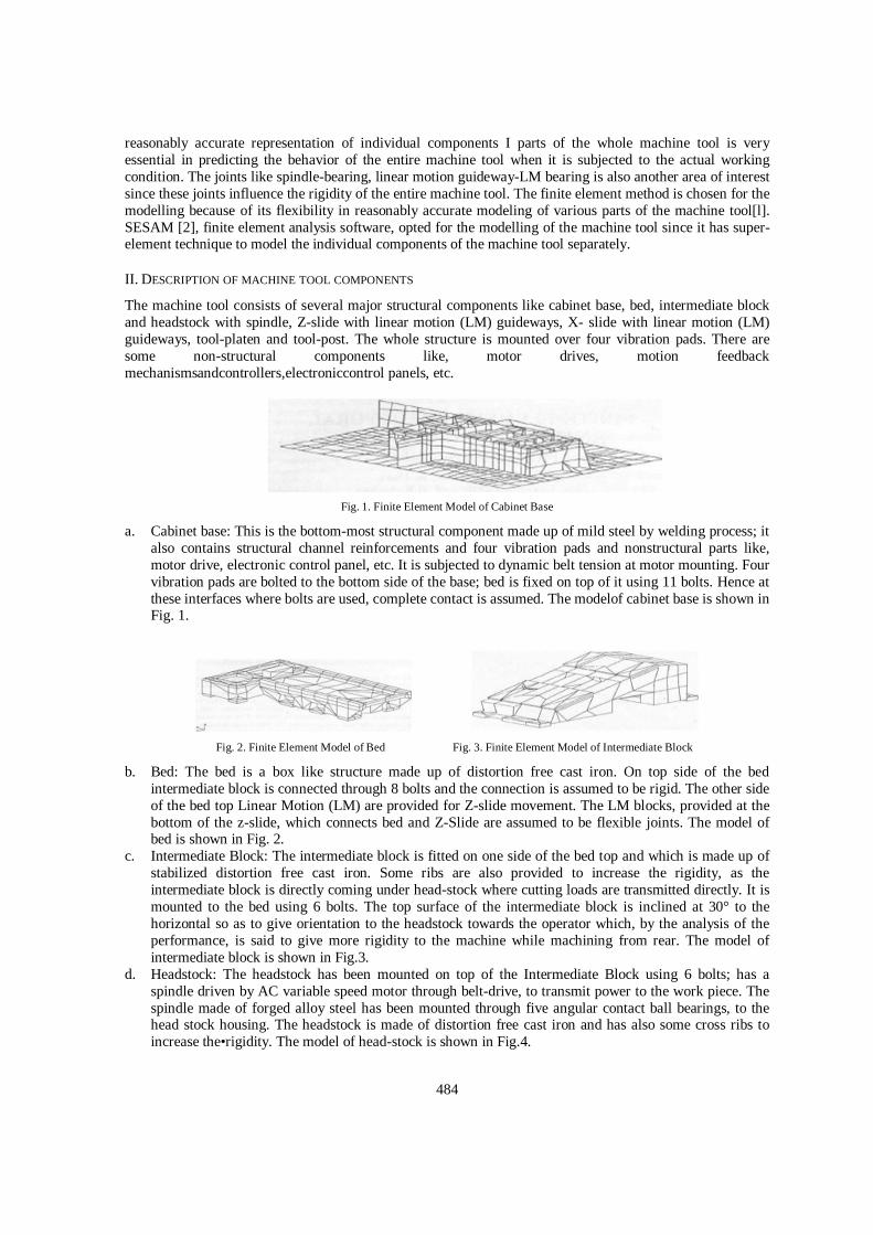
Fig. 1. Finite Element Model of Cabinet Base
a. Cabinet base: This is the bottom-most structural component made up of mild steel by welding process; it also contains structural channel reinforcements and four vibration pads and nonstructural parts like, motor drive, electronic control panel, etc. It is subjected to dynamic belt tension at motor mounting. Four vibration pads are bolted to the bottom side of the base; bed is fixed on top of it using 11 bolts. Hence at these interfaces where bolts are used, complete contact is assumed. The modelof cabinet base is shown in Fig. 1.
Fig. 2. Finite Element Model of Bed Fig. 3. Finite Element Model of Intermediate Block
b. Bed: The bed is a box like structure made up of distortion free cast iron. On top side of the bed intermediate block is connected through 8 bolts and the connection is assumed to be rigid. The other side of the bed top Linear Motion (LM) are provided for Z-slide movement. The LM blocks, provided at the bottom of the z-slide, which connects bed and Z-Slide are assumed to be flexible joints. The model of bed is shown in Fig. 2.
c. Intermediate Block: The intermediate block is fitted on one side of the bed top and which is made up of stabilized distortion free cast iron. Some ribs are also provided to increase the rigidity, as the intermediate block is directly coming under head-stock where cutting loads are transmitted directly. It is mounted to the bed using 6 bolts. The top surface of the intermediate block is inclined at 30° to the horizontal so as to give orientation to the headstock towards the operator which, by the analysis of the performance, is said to give more rigidity to the machine while machining from rear. The model of intermediate block is shown in Fig.3.
d. Headstock: The headstock has been mounted on top of the Intermediate Block using 6 bolts; has a spindle driven by AC variable speed motor through belt-drive, to transmit power to the work piece. The spindle made of forged alloy steel has been mounted through five angular contact ball bearings, to the head stock housing. The headstock is made of distortion free cast iron and has also some cross ribs to increase the•rigidity. The model of head-stock is shown in Fig.4.

485
Fig. 4. Finite Element Model of Headstock Fig. 5. Finite Element Model of Z-Slide
e. Z-Slide: The Z-slide is mounted on the LM rails (twonumbers,one on each side of the bed) provided over the bed which facilitates transverse movement in the Z-direction (in the direction of spindle axis). The four LM blocks (two for each rail) provided at the bottom of the z-slide contacts LM rails on the bed through LM bearings. The Z-slide obtains its power from the AC servomotor drive through ball screw which rotates and gives linear motion to nut screwed to the ball screw. Since Z-slide is rigidly connected to the nut, it also moves along with nut. The to-and-fro motion for Z-slide is obtained by changing the direction of rotation of ball-screw. On top of Z-slide, two LM rails are provided for X-slide transverse movement. Z-slide is made of stabilized distortion free cast iron. The top surface of Z-slide is 30° inclined down towards the operator. The model of Z-slide is shown in Fig. 5.
Fig. 6. Finite Element Model of X-Slide Fig.7. Finite Element Model of Tool Assembly
f. X-Slide: The X-slide is fitted onto the LM rails provided on the Z -slide. The LM blocks provided at bottom of the X-slide make contact with the LM rails through LM bearings. The X-slide gives transverse movement to the tool-tip in X-direction (in the direction of towards or away from the operator). It also works like Z-slide with ball screw obtaining power from AC servo motor and transferring to ball screw nut as linear motionandthusmovingtheX-slideto-and-fro. The top of the X-slidehas been provided with dovetailguide-waysfor fitting the tool platen. The model of X-slide is shown in Fig. 6.
g. Tool-platen and tool-post: The tool-platen is mounted on the X -slide rigidly and has the provision for mounting tool post anywhere. The tool post is mounted on the tool-platen by 2 screws each for rear and front and the tool is clamped on the tool-post by 4 screws. The model of tool platen and tool post assemblyis shown in Fig. 7.
III. MODELLING OF MACHINE TOOL
Each component of the machine tool consists of several parts with varying dimensions; hence line elements, surface elements and solid elements are needed to model the diversifying nature of the parts appropriately. The drawing of each part of every component is studied properlyand is transformed into equivalent finite element geometric model. Each component of the machine tool is modelled as a separate substructure (super-element). These super elements are transformed, copied and assembled, to suit the machine tool geometry configuration.
Guidelines for generation of finite element models Some of the guidelines employed, during the process of generating finite element geometry from the drawing, are listed below: Walls with thickness less than 17 mm are modeled with shell elements. Bulky castings with intricate shapes are modeled with ISO-parametric solid elements. The bearings on the spindle and between LM rail and LM block are considered as flexible elements and
are modeled with general spring elements. The vibration pads at the foundation of the machine are modelled with general springs to simulate the
behavior of elastic properties of the vibration isolator (pad).

486
The bolt connections are so rigid that the nodes at the bolt locations are declared Super(master),aboundaryconditionrequiredfor the nodes on the mating surfaces of super-elements during assembly. Thus, making the rigid connection between the components after the assembly.
For all super elements, the main consideration is given to displacements and not for stresses. Wherever possible, linear dependency is used for shell-solid nodes to transform the rotations (X, Y and
Z directions) of the shell node to translations (X, Y and Z directions) of nearby solid nodes. For making shell-solid coupling at the vicinity of the interface between any super-elements, the penetration technique has been applied. Similarly, for beam-solid coupling, the linear dependency has been used for transforming rotations of beam nodes into translations of nearby solid nodes.
Non-structure elements like motor, control panel, coolant and lubricant pump and tanks for coolant and lubricant, various drives and mechanisms, etc. are represented through lumped concentrated masses.
The geometric model for each super-element is created with surfaces and bodies for the locations where shell and solid elements are required respectively. The mesh density at any location mainly depends upon the importance of that area in the analysis. All shell-solid couplings are also done. A. Loadings: The loadings for different conditions via. Experimental condition and worst cutting condition
are considered. They consist of belt tension and cutting forces. They are fixed forces i.e., conservative forces, which do not change their direction (w.r.t. the global) as the structure deforms. These values are authentic as these loads are measured and tabulated during the actual machining operation. The gravity load for the components has not been considered so as to study the behavior of the machine under cutting loads alone. The additional belt tension created during power transmission to the spindle is considered
B. Bearing models: Each bearing of spindle is represented as six bearings which are at 60° interval around thespindle. The stiffness property of the bearing is distributed on each spring. From the stiffness Vs load diagram of the bearing, it is observed that the behavior of the bearing, under the working loads, as non-linear. But the non-linear analysis of the entire machine tool is very costly and it is decided to study the spindle-bearing non-linear behavior locally as a separate model; the spindle is modeled as a beam and bearing as non-linear springs with non-linear material properties; from this local study, equivalent stiffness of each bearing at the spindle are obtained. This spring stiffness resulted from the local non-linear study is super-imposed over the linear spring model of the headstock spindle.
The LM bearing behavior, under the working load conditions, is linear and hence there is no need of separate local non-linear study for this joint.
IV. VALIDATION OF FINITE ELEMENT REPRESENTATION
In the experimental study, a mandrel is inserted at the nose end of the spindle and stationary condition is considered; equivalent cutting forces are calculated; the cutting loads are applied on the mandrel and the reactive forces on the tool post. Then the deflections in terms of microns at salient points on the head-stock, intermediate-block, X-slide and Z- slide are noted with respect to the top surface of the bed. Two finite element sub-assembly models are created;the first sub-assembly (Fig.1) consists of head-stock with its spindle and intermediate block; tool post, tool platen, X-slide and Z- slide with LM block bearings are the components of the second subassembly. Both subassemblies are assumed to be mounted over the bed since all the experimental results are observed over the components of these subassemblies; hence the bottom side of the intermediate-block of the first subassembly and the bottom side of the LM bearing block of the Z-slide of the second assembly are assumed to be fixed.
TABLE I. COMPARISON ·OF RADIAL DISPLACEMENTS
Dial Set- up No. Analysis (µm) Experiment
(µm) 1 11.4 10.5 2 4.3 5.0 3 1.2 1.0 4 7.3 7.0

487
TABLE II. COMPARISON OF AXIAL DISPLACEMENTS
Fig8: Finite Element Model of Sub-Assembly-1(with hidden lines removed)
The cutting loads are applied at the spindle nose whereas the reactive forces are applied on the tool post. In SESAM software, the global stiffness matrix and the load matrix are assembled from the generated element stiffness matrices and load vectors for each subassembly separately. The Cholesky Decomposition method has been used to get the displacements for each subassembly. Then the deflections from experimental results at spindle job end, head stock housing, intermediate block, tool post, tool platen, X-slide are compared with that of the finite element method as shown in Tables I & II. They show good correlation which indicates the genuineness of the modeling approach.
V. STUDY FOR THE WORST CUTTING LOAD CONDITIONS
The worst loads for facing, turning and parting-off operations from both front and rear tool post positions are calculated separately; i.e. six worst loading conditions are identified. The cutting load components are applied at the spindle job position where as the reactive forces are applied on the tool post. All super elements of the components of the machine tool are assembled to get the model for the entire machine tool as shown in Fig.2. This entire machine tool is analyzed for these six worst cutting load conditions; the deformation of the whole machine tool for one load condition is displayed in Fig.3.
Fig 9: Finite Element Model of Entire Machine Tool Assembly Fig.10: Finite Element Deformed Shape of Entire Machine Tool Assembly
As we are concerned with the rigidity of the machine, the displacements at salient points like, job tip, cutting tool tip, bolted joints and LM bearings are required to be studied. The study of displacements at various points and finding the relative displacement of each component will enable one to draw a force-flux diagram for the whole machine. The force- flux diagram indicate that how much each component is deformed and how much each component is contributing to the total deflection at the tool tip and job tip. This will also enable one to calculate the stiffness of each component and the overall stiffness of the machine. The results were post-processed to get the minimum, maximum and average displacements at the interface of the components for all the six load cases. Then from these results, deflections of each super-element is calculated. The relative rigidity of each lathe component can be visualized from the above findings and is useful for the redesign of the machine.
Dial Set-up No. Analysis (µm) Experiment (µm) 1 3.8 5.0 2 17.3 17.0 3 5.0 6.0 4 17.25 15.0 5 19.6 19.0

488
VI. REDESIGN PROCEDURE FOR THE MACHINE
The design of a structure from the finite element analysis results involves following steps: Thoroughly studying the displacement and stress distribution over the structure. Finding high sensitivity areas for displacements and stress where to add more material/stiffeners. Finding high sensitivity areas for displacements and stress where to remove unnecessary material and
simply the geometry. Since in the rigidity analysis of machine tool, the stress values are far below the design values, the consideration has been given only the displacements. Except at the headstock, intermediate block and the tool assembly, the displacements are very low everywhere. So it was decided to remove some material from these areas and also to add some stiffeners. As the FE model for each component is created from geometric model generated by points, lines, surfaces and bodies by automatic mesh generation, the modification on the areas where solid elements are used involves redefining of the corresponding geometry which has to be started from the scratch once again. It is a time consuming process. So it was decided to modify only the areas where shell elements are used. For these areas, also only the thickness defined for these shell elements are changed and no changes in other geometric details. The modifications done for the components generally are: Changes in thickness of the surfaces where shell elements are defined. Beam cross section (usually C-section) is oriented to increase the rigidity. Ribs are added, wherever possible and required. Only Cabinet Base, Bed and Z-slide have been modified as it was very difficult to modify the components because of the above said reasons.
Re-designed Machine Tool: The redesigned model allows the machine to take up higher cutting loads because of the increase in
rigidity. This means rough turning can be performed using the redesigned machine. Hence by selecting optimal cutting parameters even the hardened workpieces can be subjected for
roughing and finishing operations one after another without change of job set- ups. Such operations save the set-up time, work piece handling time, etc. and avoid theintermediate operations.
For example, normally a good surface finish component on a turning centre is achieved by rough turning-finish turning-Hardening-surface finishing operations, where the job moves from one to another machine via hardening process.
But if the optimal cutting parameters are used on this machine with appropriate cutting tool, then a hardened job can be subjected for rough turning and the fine surface finishing in the same job set-up.
To see the response of the entire structure for the finishing operation using CBN tools, another run is made with the load corresponding to the finishing operation. All the deflections of finishing operations are found to be very low compared to the existing worst load conditions.
VII. DYNAMIC ANALYSIS OF MACHINE TOOL
The component mode synthesis method is used here to extract the natural frequencies and their mode shapes of the whole structure from the eigen pairs of the individual components of the machine tool. Eigen values are extracted using Subspace Iteration method for each super element of the component. One such mode shape is displayed in Fig.4. These eigen values and their modeshapes of the whole structure are used for getting the modal frequency domain response of the given loads.
Fig. 11: A Mode shape of entire Machine Tool Assembly

489
The 45 eigen values are found at top level of the entire assembly. The modeshapes in the lower range are getting contribution mainly from the base. The dynamic response in other areas are not represented by these mode shapes. The modal response curve for the displacements in x, y and z- directions and resultant displacement at the job end and tool tip for all the six load cases are obtained for the operating frequency range 5 Hz to 19 Hz. The operating load frequencies are in the range of 5-19 Hz. Only a few natural frequencies (13.4, 13.6, 15.8, 28.0, 28.2, 35.2, 44.8, 50.4, 54.0, 61.0, …, 492.4 Hz), mainly because of base / vibration pad, are near forcing frequency range. But other higher mode shapes are getting small contribution from other super elements. The total dynamic response is contributed by two components namely, spatial contribution of load and frequency contents of load. Most of the natural frequencies in this case are well above the operating load frequency range and hence frequency part is very small. Further, only the higher natural frequencies are getting significant spatial contribution of load and not the lower natural frequencies. Hence, dynamic response in this load frequency range is almost equivalent to static response.
VIII. CONCLUSION
The machine tool consists of several components and each component has varying size of cross-sections. Hence line (beam), surface (shell) and solid (brick) finite elements are used to get reasonably accurate model of the whole machine tool. Though these elements have different degrees of freedom, coupling of these elements are properly
considered at element interfaces by using shell-solid and beam-solid connectivity. By analyzing the defection of the structure, better rigidity of the machine for facing, turning (general
cutting) and parting off operations from rear has been observed. The result shows the increase in the rigidity of the machine for these operations from rear as compared to
front. From this one can conclude that machining from rear side is always better based on the rigidity. The rigidity/weight ratio can be further increased by the following features: Modifying the spindle bearings. Selecting bearings with higher rigidity or changing bearing locations or
number of bearings will further increase the rigidity of the structure because deflections at the bearing interfaces are very significant.
Modifying the other areas where solid element representation is used.
ACKNOWLEDGEMENTS
The author is grateful to Dr. N. Seshagiri, Director General, National Informatics Centre & Special Secretary to Govt. of India and Dr. B. K. Gairola, Deputy Director General, National Informatics Centre. Also acknowledge the support received from HMT Bangalore. Bangalore.
REFERENCES
[1] V. Ramamurti,Computer Aided Design in Mechanical Engineering (Tata Mc-Graw Hill, New Delhi, 1987). DNV SESAM, SESAM (Super Element Structural Analysis Module) Software, Oslo, Norway, 1994.
[2] Basava Raju Pondhe, P. Balasubramanyam and Anil Kumar P. Katti, Finite Element Structural Analysis on CNC Lathe, part 1–Modelling; NASDYN 98, Finite Element Analysis in Industry-Recent Trends, August 7 1998, IIT Madras.
[3] Basava Raju Pondhe, P. Balasubramanyam and Anil Kumar P. Katti, Finite Element Structural Analysis on CNC Lathe, part 2 –Analysis and design; NASDYN 98, Finite Element Analysis in Industry-Recent Trends, August 7 1998, IIT Madras.
[4] N. Ashwin Kumar and Basava Raju Pondhe, Optimization and Enhancement of Load Carrying Capacity of CNC Coordinate Drilling Machine using Finite Element Method . 2013
[5] Prof. Dr. Muhsin J. Weeg, Asst. Prof. Dr. Shawkat J. AL-Tornachi, Asst. Lect. Salah H. Abid-Aun, Optimization of Light Weight Aircraft Wing Structure, Journal of Engineering and Development, Vol. 12, No. 1, March (2008) ISSN 1813-7822
[6] Innovent Engineering Solutions, ANSYS Structural Mechanics Training Manual [7] Tadeusz Stolarski, Y. Nakasone, S. Yoshimoto, Engineering Analysis with ANSYS Software