Finite Element Simulation of Flexible Roll Forming: A...
7
4th International Conference and Exhibition on Design and Production of MACHINES and DIES/MOLDS, Cesme, TURKEY, 21-23/6/2007 Finite Element Simulation of Flexible Roll Forming: A Case Study on Variable Width U Channel E. Gülçeken 1 , A. Abeé 2 , A. Sedlmaier 2 and H. Livatyali 1 1 ITU Faculty of Mech. Engr., Gümüssuyu, TR-34437 Turkey 2 data-M Gmbh, Munich, Germany ABSTRACT The process and roll design for flexible roll forming of a U channel with varying cross-section was investigated. In order to obtain a constant leg height and variable cross-section width, rotational speeds, locations, orientations and dimensions of the rolls were calculated following the unfolding prediction of the sheet metal. The proposed methodology for variable cross-section open channels was tested by a case study conducted for a typical structural U channel of St 37 sheet steel with arbitrary dimensions. The appropriate pre-cut shape (unfolded blank) was calculated. The feasibility of the process and roll design was verified on a commercial roll forming design program COPRA ® RF coupled with a finite element module furnished by MSC Marc ® . Initial simulations yield not perfect, but promising results that the proposed process and roll design method is sufficiently powerful to program a computer numerically controlled flexible roll forming machine for a given open channel. Thus, the minor leg flare at the front and back ends and leg height variation along the channel can be eliminated by a few tryouts on the actual machine. Keywords: Metal forming, Roll forming, Finite element method 1 INTRODUCTION Cold formed long sheet metal parts with constant cross- section are used almost in every area of the industry. Especially in the automotive and construction industries, beam shaped, open or closed sections with constant cross-section are produced in huge quantities [1]. Due to its high productivity and low variable cost, roll forming has more significance compared to other techniques that manufacture sections with constant cross-section. In this technique, a great output quantity per time can be attained and consequently, a profitable economical efficiency can be achieved by the continuous bending action. The length of the profile is flexible and independent from tool geometry [2]. Competing techniques such as “press brake bending” and “die bending” are preferable because of their flexibility, especially when small batch sizes are required. While the shape spectrum with conventional roll forming is almost unlimited, with press brake and die bending relatively simple shapes can be produced [3]. The most important technical advantages of the cold roll formed components are relatively homogeneous work hardening and good surface properties. Naturally coated and enameled sheets can be processed without any harm on the surface. As a result of its incremental nature, relatively hard and brittle sheet metals can be roll formed to sharp edge radii. With this aspect, roll formed sections, particularly U channels, tubes and pipes are very suitable for lightweight vehicle concepts [4]. However, conventional roll forming is limited to constant cross-section sheet metal parts whereas futuristic vehicle structure concepts require variable width and height sections and smart material combinations with new materials and new joining techniques [5, 6]. Section and orientation variations of tubes are achieved by an expensive technology tube hydro-forming. The major limitation of this approach is that high grade tubing is needed and open sections are difficult to obtain. Dreistern Company developed an advanced conventional roll forming system that produces constant width-variable height open and closed sections (Figure 1) [7]. When closed sections are needed, a second constant width strip can be welded by double seams. Flexible roll forming process is proposed to manufacture open and closed profiles with variable width. Such cross- sections are conventionally manufactured cost-intensively either by multi step processes such as blanking and stamping, bending and welding or by multi-parts [3]. In spite of the expensive manufacturing methods, there is a wide application area of long components with varying cross-sections (Figure 2). Their main application areas are vehicle, machine or mechanical structures and building and furniture industries. In the automobile industry, variable cross-section longitudinal structure components are needed in especially commercial vehicles such as vans, buses, light and heavy trucks [5]. Figure 1. Constant width variable leg height open U channels can be manufactured using pre-cut strips (after Dreistern Co.)
Transcript of Finite Element Simulation of Flexible Roll Forming: A...

4th International Conference and Exhibition on Design and Production of MACHINES and DIES/MOLDS, Cesme, TURKEY, 21-23/6/2007
Finite Element Simulation of Flexible Roll Forming: A Case Study on Variable Width U Channel
E. Gülçeken1, A. Abeé2, A. Sedlmaier2 and H. Livatyali1
1 ITU Faculty of Mech. Engr., Gümüssuyu, TR-34437 Turkey
2 data-M Gmbh, Munich, Germany
ABSTRACT The process and roll design for flexible roll forming of a U channel with varying cross-section was investigated. In order to obtain a constant leg height and variable cross-section width, rotational speeds, locations, orientations and dimensions of the rolls were calculated following the unfolding prediction of the sheet metal. The proposed methodology for variable cross-section open channels was tested by a case study conducted for a typical structural U channel of St 37 sheet steel with arbitrary dimensions. The appropriate pre-cut shape (unfolded blank) was calculated. The feasibility of the process and roll design was verified on a commercial roll forming design program COPRA® RF coupled with a finite element module furnished by MSC Marc®. Initial simulations yield not perfect, but promising results that the proposed process and roll design method is sufficiently powerful to program a computer numerically controlled flexible roll forming machine for a given open channel. Thus, the minor leg flare at the front and back ends and leg height variation along the channel can be eliminated by a few tryouts on the actual machine. Keywords: Metal forming, Roll forming, Finite element method
1 INTRODUCTION Cold formed long sheet metal parts with constant cross-section are used almost in every area of the industry. Especially in the automotive and construction industries, beam shaped, open or closed sections with constant cross-section are produced in huge quantities [1]. Due to its high productivity and low variable cost, roll forming has more significance compared to other techniques that manufacture sections with constant cross-section. In this technique, a great output quantity per time can be attained and consequently, a profitable economical efficiency can be achieved by the continuous bending action. The length of the profile is flexible and independent from tool geometry [2]. Competing techniques such as “press brake bending” and “die bending” are preferable because of their flexibility, especially when small batch sizes are required. While the shape spectrum with conventional roll forming is almost unlimited, with press brake and die bending relatively simple shapes can be produced [3].
The most important technical advantages of the cold roll formed components are relatively homogeneous work hardening and good surface properties. Naturally coated and enameled sheets can be processed without any harm on the surface. As a result of its incremental nature, relatively hard and brittle sheet metals can be roll formed to sharp edge radii. With this aspect, roll formed sections, particularly U channels, tubes and pipes are very suitable for lightweight vehicle concepts [4].
However, conventional roll forming is limited to constant cross-section sheet metal parts whereas futuristic vehicle structure concepts require variable width and height sections and smart material combinations with new materials and new joining techniques [5, 6]. Section and orientation variations of tubes are achieved by an
expensive technology tube hydro-forming. The major limitation of this approach is that high grade tubing is needed and open sections are difficult to obtain. Dreistern Company developed an advanced conventional roll forming system that produces constant width-variable height open and closed sections (Figure 1) [7]. When closed sections are needed, a second constant width strip can be welded by double seams.
Flexible roll forming process is proposed to manufacture open and closed profiles with variable width. Such cross-sections are conventionally manufactured cost-intensively either by multi step processes such as blanking and stamping, bending and welding or by multi-parts [3]. In spite of the expensive manufacturing methods, there is a wide application area of long components with varying cross-sections (Figure 2). Their main application areas are vehicle, machine or mechanical structures and building and furniture industries. In the automobile industry, variable cross-section longitudinal structure components are needed in especially commercial vehicles such as vans, buses, light and heavy trucks [5].
Figure 1. Constant width variable leg height open U channels can be manufactured using pre-cut strips (after Dreistern Co.)

Figure 2. Some profile concepts with varying cross-sections [6]
For most structural applications, stiffness is relatively more important than strength, and stiffness-to-weight ratio is another significant advantage of flexible roll formed steel parts. When vertically loaded, longer web portions of a U channel can be located at the zones of highest bending stresses to keep the weight minimal. Roll forming, either conventional or flexible, produces a homogeneous work hardening along the bent edge as well as a homogeneous residual stress distribution. This makes structural parts that are more reliable and more corrosion resistant than those made by tube hydro-forming. The variable location and length of the longer portion of the U channel web (in vertical position) enables commercial vehicles with various lengths (Figure 3).
The main draw-back of flexible roll forming is that it requires a complex machine run by minimum six servo axes to be numerically controlled. Design of the variable width blank (pre-cut shape) according to the given channel geometry, design of the roll set (shapes and sizes) that will bend the section gradually to 90 degrees, design of the tool paths (roll axis trajectories) that keep the leg height constant, determining the rotational speed function of the rolls with respect to time to keep the slippage minimal; simulation of the highly non-linear process using the most appropriate finite element algorithm and model are the main research issues [8, 9].
2 OBJECTIVES AND APPROACH The main objective of this study is to develop of a flexible roll forming method and determine of its correct process parameters as a function of time to achieve a given U channel that has varying cross-section (web width). An arbitrary, however, typical U channel was developed and studied, as a case study for the flexible roll forming process.
Figure 3. Light trucks with different wheel bases [5]
The CAD model of the desired shape was generated and the process simulation was carried out using a commercial roll forming design program COPRA® RF coupled with a finite element module of MSC Marc®.
The steps of this investigation were:
1) Model a given U channel that has varying cross-section and determine the pre-cut shape by unfolding calculations.
2) Define tool path for the rolls to follow during the process, to achieve the constant leg height and variable web width along the part.
3) Determine the motion of rotation center of the rolls by keeping perpendicularity with the tool path.
4) Design the roll diameter, length, fillet radii and other geometric features based on process constraints.
5) Simulate the roll forming process on a commercial finite element program using flexible roll kinematics with six degrees of freedom.
6) Evaluate effects of process parameters based on simulation results, and determine of the optimal position of the roll stations and deformation steps.
7) Simplify the parameters in the computer environment in order to develop a roll control program.
3 DESIGN OF THE FLEXIBLE ROLL FORMING PROCESS AND ROLLS
Design of the roll forming process and rolls for a given product remains more of an experience based art rather than science. Even for a simple constant cross-section U channel, there are many different process and roll design alternatives that are commercially used. One of simplest processes uses a bending scheme of 30, 60 and 90 deg. rolls as shown in Figure 4. This particular design uses vertical idler rolls in the 60 and 90 degree stations that enable practical channel width adjustment when the center (top) roll is split into two parts. The split top roll design can also be used in flexible roll forming to make a variable (web) width U channel, if the top and vertical roll center and axis displacements with respect to time can be controlled accurately.
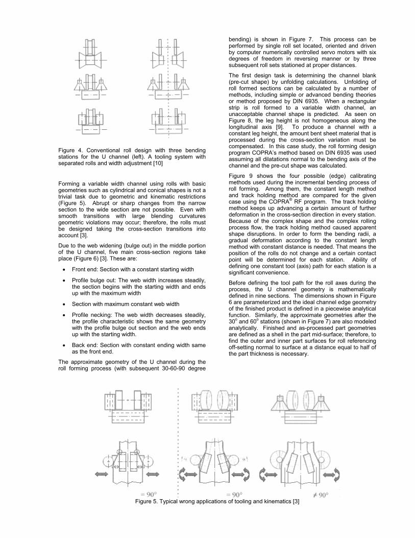
Figure 4. Conventional roll design with three bending stations for the U channel (left). A tooling system with separated rolls and width adjustment [10]
Forming a variable width channel using rolls with basic geometries such as cylindrical and conical shapes is not a trivial task due to geometric and kinematic restrictions (Figure 5). Abrupt or sharp changes from the narrow section to the wide section are not possible. Even with smooth transitions with large blending curvatures geometric violations may occur; therefore, the rolls must be designed taking the cross-section transitions into account [3].
Due to the web widening (bulge out) in the middle portion of the U channel, five main cross-section regions take place (Figure 6) [3]. These are:
• Front end: Section with a constant starting width
• Profile bulge out: The web width increases steadily, the section begins with the starting width and ends up with the maximum width
• Section with maximum constant web width
• Profile necking: The web width decreases steadily, the profile characteristic shows the same geometry with the profile bulge out section and the web ends up with the starting width.
• Back end: Section with constant ending width same as the front end.
The approximate geometry of the U channel during the roll forming process (with subsequent 30-60-90 degree
bending) is shown in Figure 7. This process can be performed by single roll set located, oriented and driven by computer numerically controlled servo motors with six degrees of freedom in reversing manner or by three subsequent roll sets stationed at proper distances.
The first design task is determining the channel blank (pre-cut shape) by unfolding calculations. Unfolding of roll formed sections can be calculated by a number of methods, including simple or advanced bending theories or method proposed by DIN 6935. When a rectangular strip is roll formed to a variable width channel, an unacceptable channel shape is predicted. As seen on Figure 8, the leg height is not homogeneous along the longitudinal axis [9]. To produce a channel with a constant leg height, the amount bent sheet material that is processed during the cross-section variation must be compensated. In this case study, the roll forming design program COPRA’s method based on DIN 6935 was used assuming all dilatations normal to the bending axis of the channel and the pre-cut shape was calculated.
Figure 9 shows the four possible (edge) calibrating methods used during the incremental bending process of roll forming. Among them, the constant length method and track holding method are compared for the given case using the COPRA® RF program. The track holding method keeps up advancing a certain amount of further deformation in the cross-section direction in every station. Because of the complex shape and the complex rolling process flow, the track holding method caused apparent shape disruptions. In order to form the bending radii, a gradual deformation according to the constant length method with constant distance is needed. That means the position of the rolls do not change and a certain contact point will be determined for each station. Ability of defining one constant tool (axis) path for each station is a significant convenience.
Before defining the tool path for the roll axes during the process, the U channel geometry is mathematically defined in nine sections. The dimensions shown in Figure 6 are parameterized and the ideal channel edge geometry of the finished product is defined in a piecewise analytical function. Similarly, the approximate geometries after the 30o and 60o stations (shown in Figure 7) are also modeled analytically. Finished and as-processed part geometries are defined as a shell in the part mid-surface; therefore, to find the outer and inner part surfaces for roll referencing off-setting normal to surface at a distance equal to half of the part thickness is necessary.
Figure 5. Typical wrong applications of tooling and kinematics [3]

Figure 6. Dimensions of the U Channel
Figure 7. a) The 30o b) 60o and c) final (90o) 3D forms of the U-channel during flexible roll forming
Figure 8. Flexible roll forming application on rectangular blank (300x40x2 mm; COPRA RF FEA and MSC Marc)
(a) (b)
(c) (d)
Figure 9. Edge calibrating methods: a) Constant radius method b) Constant length method c) Angle/Radius method and d) Track holding method
To simplify the roll design and motions, all rolls are selected to be cylindrical. Roll axis location and orientation as functions of time (tool path) are defined using tangency constraints and off-setting normal to the part surface (similar to the unfolding procedure).
Determining the path of rotation centers of the rolls is conducted by keeping the perpendicularity with tool path under the track holding edge calibration constraint. Next, values of the roll diameters, lengths and fillet radii are finalized based on the pre-determined process constraints. Diameters of the rolls are related with the transition area between two straight cross-sections of the channel. The greater angle of the transition is, the smaller the rolls must be in order to prevent a possible collision with the sheet (Figure 5).
The nonlinear mathematical definition of the roll motions in six degrees of freedom can not be used as are in the programming of the servo axes. Therefore, the tool paths and rotation center loci are simplified into piecewise linear trajectories in order to develop a roll control program in the computer numerical control environment. This also simplifies the finite element programming.
4 FINITE ELEMENT MODEL
The channel material is common structural sheet steel, St 37 (ASTM A284 Steel, grade C) with a modulus of elasticity of 210 GPa and Poisson’s ratio of 0.3. Under Von Misses yield criteria, flow stress of the steel was modeled as an isotropic elastic-rigid strain hardening plastic metal using Swift’s (Krupkowski’s) extended power law,

σ = 700(0.001 + ε)0.2
and the piecewise linear method was selected to model strain rate effects.
Various element types were evaluated and finally mechanical 3-D 8-noded hexahedral volume element of Type 7 (full integration) was selected from the Marc element library as the most stable element type for the pseudo-static implicit solver coupled with the roll forming design program COPRA RF. Element type 7 uses tri-linear interpolation functions, the strains tend to be constant throughout the element. This results in a poor representation of shear behavior. The shear (or bending) characteristics can be improved by using alternative interpolation functions. Thus, the “assumed strain” procedure is flagged through the geometric properties option. This element is preferred over higher-order elements when used in contact analysis. The stiffness of this element is formed using eight-point Gaussian integration. After meshing, the 325.16 mm long half shape sheet contained 1274 elements.
For nearly incompressible behavior, including plastic deformation, it is advantageous to use an alternative integration procedure. “Constant dilatation” method, which eliminates potential element locking, was selected. A mesh with hexahedral elements is generally more accurate, easier to visualize, simpler to edit and requires fewer elements than those meshes that contain tetrahedral elements (Figure 10). The roll surfaces, on the other hand, were modeled using rigid shells.
There are three possible ways to control the rigid contact-bodies, by referencing the velocity, position or load. Each way can be chosen to execute the movement of the flattener rolls. However, defining the translation move in addition with the rotation in many axes is only possible by the load control method. In kinematical movement trials, rotation of the rolls was succeeded with position control method as well, but the option was capable of rotation only around one axis. Therefore, the flattener rolls were assigned position control method (only translational) and the rotational rolls had load control (translational and rotational) enabling six degrees of freedom.
The position control of the flattener rolls is conducted by defining a forward move in the longitudinal (Z) direction. This movement is defined in a table that is used for all stations in the simulation (Figure 11). The load control definition is performed by defining two additional nodes, called the “Control Node” and the “Auxiliary Node”. These nodes were the references for defining the concurrent rotational and translational movements of the rolls. After defining these nodes for each station, the necessary movement definitions were given in the boundary condition tables. Before defining the tables
these points must be inserted to the right position, which is the rotational point location.
After introducing the contact bodies, contact tables were defined to present the contacts to the simulation and calculate the contact timing. That provides the simulation to count only the deformation in the rigid bodies that are defined in the contact table and accelerates the calculation time. According to these contact tables (or list of contact events) “Load Cases” which assign the durations of contact in the tables were defined in the next step. The contact time intervals also determine the destiny of a correct result and they must overlay with the real production time. It has been assumed that the sheet metal moves 1 mm per second in longitudinal direction, and the total process time was 650 seconds.
In the updated Lagrange formulation of MSC Marc, element quantities are evaluated with respect to a reference system that is updated by the current displacements using full Newton-Raphson iteration. The program uses Cauchy (true) stresses and the corresponding true strains. For small strains, this procedure is typically used for beam and shell structures where the rotations are large. It should be used in conjunction with the “Large displacement” option needed for linearized buckling analysis with a nonlinear preloading [9].
5 PROCESS SIMULATION
Simulating the flexible roll forming model took 3-4 CPU hours with a Pentium 4 processor and 1 GB RAM. For such a complex problem, this fairly fast simulation is obtained by the usage of single brick element in the thickness direction that limited the total element number to 1274. In contrast to academic circles, these kind of rough models are more preferable in the industrial environment where fast solutions are expected.
The dimensions of the formed channel were the most significant issue to evaluate in this investigation. Among them, channel leg height, shape and angle are the most critical ones. Figure 12 shows front view of the channel. Accordingly, there is a slight outwards curling at front end called end flare. In all simulations, this deviation was observed. At back end, a relatively smaller flare is again observed. These defects tend to occur in roll forming of pre-cut strips as well, and they are related to the residual stress pattern (Figure 13). The widening and narrowing of the channel may have amplified them. Thus, the normal stress distribution asymmetry explains the difference between the front and the end. Nevertheless, flexible roll forming has the programmability advantage that flaring may be compensated for.
Figure 10. Sheet metal blank and rolls as rigid contact bodies. (COPRA RF FEA and MSC Marc)
x
y
z

Figure 11. Distances between roll stations (COPRA RF FEA and MSC Marc)
Figure 12. End flare at the front (nodes at outer surface)
Figure 13. Normal stress distribution. Compressive stresses are shown with their directions
The dimensional tolerance of the leg height was set as ±0.5 mm. Figure 14 illustrates variation of the leg height in the axial direction. Range was measured as 2 mm where maximum leg height was 22.9 mm, the minimum was 20.99 and the part specification was 22 mm. One of the sources of error may be the roughness of the finite element mesh. Since the original objective o the investigation was to develop process and roll design, a rough mesh with single solid element in thickness direction was preferred for fast solutions. In addition, only
two elements exist in the 90 degree bending area. This may only be sufficient to cause the 2 mm leg height variation. Additional errors may have come from unfolding prediction and center of rotation calculations.
The leg height variation may also have originated from the location of roll center rotation. An average position was assigned in the finite element program. For some arc regions, the true rotational point locations were changed intentionally to reduce the estimated deviation and balance it on the both arc regions. Nevertheless, the fundamentally geometric process design and the relatively rough simulations gave part geometry close to the design specifications. Improving the finite element mesh and slightly modifying the roll center of rotation leg height variation may be minimized.
6 SUMMARY AND CONCLUSIONS
The main objective of this investigation was to explore the feasibility of the flexible roll forming using numerical modeling and simulation. In addition, 3-D roll kinematics with six degrees of freedom has been studied. A case study on a typical variable width U channel was performed and the results are presented with methodic explanations.
With the restriction that came from the finite element program, the rotational centers could not be moved and an average position was specified for minimum deviation. It is observed that the rotational center must not be fixed during the process because of the different sides of the centers of curvature that exist in the defined profile.
(mm)
(mm)
60 mm 60 mm 60 mm 60 mm 60 mm Pre-cut Sheet Length= 325.16 mm
45.6
(MPa)
36.8
28.1
19.3
10.4
1.7
-7.1
-15.8
-24.6
-32.4
-42.3 x
z
(mm)
(mm)

Figure 14. Leg height progression along the channel (purple line is the leg height progression data from COPRA RF FEA, green line is the required height)
According to the finite element analysis results, the overall part dimensions fit the user definition closely. After a number of iterations the leg height deviation was reduced to ±1 mm, which is still out the tolerance limitations for a roll formed profile. The end flare at the front and back sides can be eliminated by roll position adjustment.
In the simulations, only the dilatation of bending zone was taken into account. However, excessive elongation was also observed on the leg widening and narrowing zones in the longitudinal direction. although, an exaggerated flexibility factor was assumed, a result of ±1 mm variation was obtained. This effect may influence the result, depending on the channel type and leg geometry. Thus, additional dilatation must not be underestimated in further studies.
Generally, design of a roll forming machine is realized with several vertical roll pairs and supporting flattener roll sets. In a flexible roll forming machine design, the flexible rolls can be assembled to a six axis servo mechanism. In the conventional roll forming process the moving part is always the sheet metal, however in this application the rolls can move along the fixed sheet metal. This eliminates the need of flattener rolls and one flexible roll pair can work for all bending stations by changing the bending angle after each pass. As one bending step is achieved in the forward direction, an upper bending step could be achieved in the backward direction. This design increases the productivity and also reduces the number of rolls.
As long as the kinematics of the rolls can be modeled up to six degrees of freedom, various types of channels can be designed to roll formed. Figure 15 shows a futuristic hat section that is designed to be manufactured with flexible roll forming in the future.
Figure 15. Application of flexible roll forming for different channel types
REFERENCES
[1] DIN 8586, 1971. Fertigungsverfahren Biege-umformen, Berlin, Köln.
[2] Busse, D., 1993. Verbesserung der Qualität von Standardprofilen durch Schwingungsüberlagerung im kontinuierlichen Walzprofilierbetrieb Dr.-Ing. Dissertation, TH Darmstadt.
[3] Istrate, A., 2002. Verfahrensentwicklung zum Walzprofilieren von Strukturbauteilen mit der Längsachse veränderlichen Querschnitten, Dr-Ing. Dissertation, TU Darmstadt.
[4] Theis, H. E., 1999. Handbook of Metal forming Processes, Herr-Voss Corp., Callery, Pennsylvania.
[5] Haldenwanger, H.G., 2000. Leichtbaustrategien mit neuen Werkstoffen-Verfahren als Funktion des kostenträchtigen Produktionsentstehungs-prozesses, Euroform Werkstofftagung für die Automobilindustrie – Werkstoffvielfalt im Automobil – eine Herausforderung.
[6] Schmitt, J. and Feitzelmayer, K., 2000. „Leichtbau bei MAN-Nutzfahrzeugen Fortschritte innerhalb von 15 Jahren“, Dresdner Leichtbausymposium, Dresden.
[7] Dresitern GmbH, 2007, www.dreistern.com
[8] Sedlmaier, A., 2004. FEM gestützte Auslegung von Rollensätzen - Konstruktion und Auslegung von Rollensätzen mit geometriebasierten Methoden, VDI Wissenforum Walzprofilieren, Darmstadt.
[9] Abee, A., 2004. Increasing Roll Forming Know-How for Practical Verification and Improving Production Quality by use of Numerical Simulation, ICIT 2003 4th Int. Conference on Industrial Tools, Bled.
[10] Groche, P., Breitenbach, v.G., Jöckel, M. and Zettler, A., 2002. New tooling concepts for future roll forming applications, Institute for Production Engineering and Forming Machines, Technische Universität Darmstadt.
[11] COPRA® RF Software, 2005. Deformation Technology (Simulation), Open Sections & Closed Sections, Trapezoidal Sections, User Manual, data-M GmbH, Munich. (www.datam.com)
[12] MSC Marc User’s Guide, 2005. MSC.Marc Mentat.