Finite Element Method Applied in Electromagnetic NDTE… · Finite Element Method Applied in...
15
J Nondestruct Eval (2016) 35:39 DOI 10.1007/s10921-016-0356-6 Finite Element Method Applied in Electromagnetic NDTE: A Review Marek Augustyniak 1,2 · Zbigniew Usarek 1 Received: 8 December 2015 / Accepted: 31 May 2016 © The Author(s) 2016. This article is published with open access at Springerlink.com Abstract The paper contains an original comprehensive review of finite element analysis (FEA) applied by researchers to calibrate and improve existing and develop- ing electromagnetic non-destructive testing and evaluation techniques, including but not limited to magnetic flux leak- age (MFL), eddy current testing, electromagnetic-acoustic transducers (EMATs). Premium is put on the detection and modelling of magnetic field, as the vast majority of ENDT involves magnetic induction, either as a primary variable MFL or a complementary phenomenon (EC, EMATs). FEA is shown as a fit-for-purpose tool to design, understand and optimise ENDT systems, or a Reference for other modelling algorithms. The review intentionally omits the fundamen- tals of FEA and detailed principles of NDT. Strain-stress FEA applications in NDT, especially in ultrasonography and hole-drilling methodology, deserve as well a separate study. Keywords Finite element method · Electromagnetic non-destructive testing · MFL · Eddy current testing · EMATs 1 Introduction Non-destructive testing and evaluation (NDT, NDE or NDTE) attracts lasting attention driven by demands of relia- bility and economic service of engineering structures. Con- temporary engineering—and NDT development in particular B Marek Augustyniak [email protected] 1 Gdansk University of Technology, 80-233 Gda´ nsk, Poland 2 DES ART Ltd, 81-969 Gdynia, Poland —becomes increasingly associated with numerical mod- elling [1]. Among available modelling approaches, finite element analysis (FEA) has taken the lead in both academic and commercial applications. It is much more versatile than any analytical model. As compared to two major concur- rent numerical approaches, i.e. boundary element method (BEM) and finite difference method (FDM), it is more intuitive, subject to less fundamental limitations (e.g. con- cerning unstructured mesh, nonlinearities or couplings) and is promptly available in several computer tools provided with a comfortable graphical user interface (GUI) and exhaustive user manuals. Finite element analysis can complement and partially replace experimental ENDT for reasons listed below: – the simulation allows for generating scenarios with a full control over all variables and phenomena – it is impractical and in some cases unfeasible to measure electromagnetic parameters (magnetic induction, current density) inside a solid specimen [2], whereas these can be easily retrieved from FEA – the measurement of a detailed distribution of the mag- netic and/or electric field around an engineering object is time-consuming and requires painstaking data process- ing; by contrast, FEA software directly generates the resulting contour plots – FEA tends to be more economic than experiment, espe- cially when generating an array of results for subsequent inverse problem solution Table 1 presents authors’ attempt to arrange the techniques by the frequency range and the level of complexity. The latter variable corresponds to both the underlying physics and the practical difficulties in obtaining reliable results by either experiment or simulation. Any ENDT method, 123 More info about this article: http://www.ndt.net/?id=20240
Transcript of Finite Element Method Applied in Electromagnetic NDTE… · Finite Element Method Applied in...

J Nondestruct Eval (2016) 35:39
DOI 10.1007/s10921-016-0356-6
Finite Element Method Applied in Electromagnetic NDTE:A Review
Marek Augustyniak1,2· Zbigniew Usarek1
Received: 8 December 2015 / Accepted: 31 May 2016
© The Author(s) 2016. This article is published with open access at Springerlink.com
Abstract The paper contains an original comprehensive
review of finite element analysis (FEA) applied by
researchers to calibrate and improve existing and develop-
ing electromagnetic non-destructive testing and evaluation
techniques, including but not limited to magnetic flux leak-
age (MFL), eddy current testing, electromagnetic-acoustic
transducers (EMATs). Premium is put on the detection and
modelling of magnetic field, as the vast majority of ENDT
involves magnetic induction, either as a primary variable
MFL or a complementary phenomenon (EC, EMATs). FEA
is shown as a fit-for-purpose tool to design, understand and
optimise ENDT systems, or a Reference for other modelling
algorithms. The review intentionally omits the fundamen-
tals of FEA and detailed principles of NDT. Strain-stress
FEA applications in NDT, especially in ultrasonography and
hole-drilling methodology, deserve as well a separate study.
Keywords Finite element method · Electromagnetic
non-destructive testing · MFL · Eddy current testing ·
EMATs
1 Introduction
Non-destructive testing and evaluation (NDT, NDE or
NDTE) attracts lasting attention driven by demands of relia-
bility and economic service of engineering structures. Con-
temporary engineering—and NDT development in particular
B Marek Augustyniak
1 Gdansk University of Technology, 80-233 Gdansk, Poland
2 DES ART Ltd, 81-969 Gdynia, Poland
—becomes increasingly associated with numerical mod-
elling [1]. Among available modelling approaches, finite
element analysis (FEA) has taken the lead in both academic
and commercial applications. It is much more versatile than
any analytical model. As compared to two major concur-
rent numerical approaches, i.e. boundary element method
(BEM) and finite difference method (FDM), it is more
intuitive, subject to less fundamental limitations (e.g. con-
cerning unstructured mesh, nonlinearities or couplings) and
is promptly available in several computer tools provided with
a comfortable graphical user interface (GUI) and exhaustive
user manuals.
Finite element analysis can complement and partially
replace experimental ENDT for reasons listed below:
– the simulation allows for generating scenarios with a full
control over all variables and phenomena
– it is impractical and in some cases unfeasible to measure
electromagnetic parameters (magnetic induction, current
density) inside a solid specimen [2], whereas these can
be easily retrieved from FEA
– the measurement of a detailed distribution of the mag-
netic and/or electric field around an engineering object is
time-consuming and requires painstaking data process-
ing; by contrast, FEA software directly generates the
resulting contour plots
– FEA tends to be more economic than experiment, espe-
cially when generating an array of results for subsequent
inverse problem solution
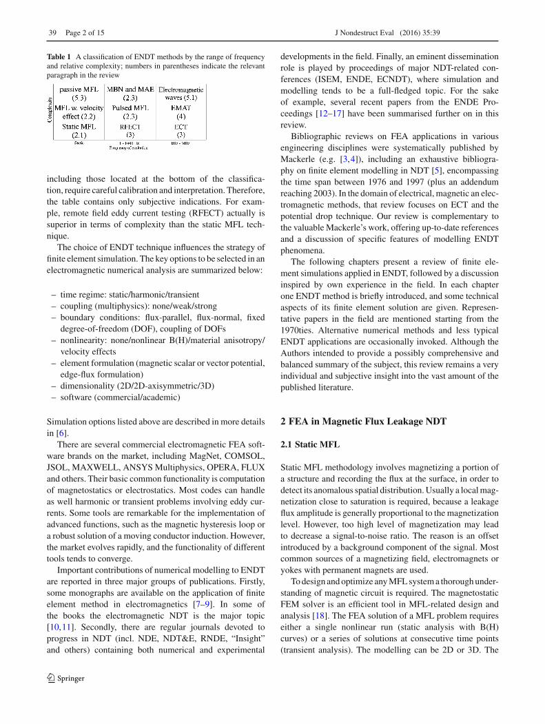
Table 1 presents authors’ attempt to arrange the techniques
by the frequency range and the level of complexity. The
latter variable corresponds to both the underlying physics
and the practical difficulties in obtaining reliable results
by either experiment or simulation. Any ENDT method,
123
Mor
e in
fo a
bout
this
art
icle
: ht
tp://
ww
w.n
dt.n
et/?
id=
2024
0
39 Page 2 of 15 J Nondestruct Eval (2016) 35:39
Table 1 A classification of ENDT methods by the range of frequency
and relative complexity; numbers in parentheses indicate the relevant
paragraph in the review
including those located at the bottom of the classifica-
tion, require careful calibration and interpretation. Therefore,
the table contains only subjective indications. For exam-
ple, remote field eddy current testing (RFECT) actually is
superior in terms of complexity than the static MFL tech-
nique.
The choice of ENDT technique influences the strategy of
finite element simulation. The key options to be selected in an
electromagnetic numerical analysis are summarized below:
– time regime: static/harmonic/transient
– coupling (multiphysics): none/weak/strong
– boundary conditions: flux-parallel, flux-normal, fixed
degree-of-freedom (DOF), coupling of DOFs
– nonlinearity: none/nonlinear B(H)/material anisotropy/
velocity effects
– element formulation (magnetic scalar or vector potential,
edge-flux formulation)
– dimensionality (2D/2D-axisymmetric/3D)
– software (commercial/academic)
Simulation options listed above are described in more details
in [6].
There are several commercial electromagnetic FEA soft-
ware brands on the market, including MagNet, COMSOL,
JSOL, MAXWELL, ANSYS Multiphysics, OPERA, FLUX
and others. Their basic common functionality is computation
of magnetostatics or electrostatics. Most codes can handle
as well harmonic or transient problems involving eddy cur-
rents. Some tools are remarkable for the implementation of
advanced functions, such as the magnetic hysteresis loop or
a robust solution of a moving conductor induction. However,
the market evolves rapidly, and the functionality of different
tools tends to converge.
Important contributions of numerical modelling to ENDT
are reported in three major groups of publications. Firstly,
some monographs are available on the application of finite
element method in electromagnetics [7–9]. In some of
the books the electromagnetic NDT is the major topic
[10,11]. Secondly, there are regular journals devoted to
progress in NDT (incl. NDE, NDT&E, RNDE, “Insight”
and others) containing both numerical and experimental
developments in the field. Finally, an eminent dissemination
role is played by proceedings of major NDT-related con-
ferences (ISEM, ENDE, ECNDT), where simulation and
modelling tends to be a full-fledged topic. For the sake
of example, several recent papers from the ENDE Pro-
ceedings [12–17] have been summarised further on in this
review.
Bibliographic reviews on FEA applications in various
engineering disciplines were systematically published by
Mackerle (e.g. [3,4]), including an exhaustive bibliogra-
phy on finite element modelling in NDT [5], encompassing
the time span between 1976 and 1997 (plus an addendum
reaching 2003). In the domain of electrical, magnetic an elec-
tromagnetic methods, that review focuses on ECT and the
potential drop technique. Our review is complementary to
the valuable Mackerle’s work, offering up-to-date references
and a discussion of specific features of modelling ENDT
phenomena.
The following chapters present a review of finite ele-
ment simulations applied in ENDT, followed by a discussion
inspired by own experience in the field. In each chapter
one ENDT method is briefly introduced, and some technical
aspects of its finite element solution are given. Represen-
tative papers in the field are mentioned starting from the
1970ties. Alternative numerical methods and less typical
ENDT applications are occasionally invoked. Although the
Authors intended to provide a possibly comprehensive and
balanced summary of the subject, this review remains a very
individual and subjective insight into the vast amount of the
published literature.
2 FEA in Magnetic Flux Leakage NDT
2.1 Static MFL
Static MFL methodology involves magnetizing a portion of
a structure and recording the flux at the surface, in order to
detect its anomalous spatial distribution. Usually a local mag-
netization close to saturation is required, because a leakage
flux amplitude is generally proportional to the magnetization
level. However, too high level of magnetization may lead
to decrease a signal-to-noise ratio. The reason is an offset
introduced by a background component of the signal. Most
common sources of a magnetizing field, electromagnets or
yokes with permanent magnets are used.
To design and optimize any MFL system a thorough under-
standing of magnetic circuit is required. The magnetostatic
FEM solver is an efficient tool in MFL-related design and
analysis [18]. The FEA solution of a MFL problem requires
either a single nonlinear run (static analysis with B(H)
curves) or a series of solutions at consecutive time points
(transient analysis). The modelling can be 2D or 3D. The
123

J Nondestruct Eval (2016) 35:39 Page 3 of 15 39
material data consists of magnetization curves defined up to
saturation (µR ∼ 1.0) and possibly electrical conductivities
in the transient problem. The smoothness of B(H) curves can
be essential for obtaining convergent solution [19]. The mesh
density may be uniform, and the standard recommendation
holds as to using the hexahedral element shapes whenever it
is possible. The resulting vector fields (primary: B—the mag-
netic induction, and secondary: J—the current density) are
vector real values. The numerical methods which cannot deal
with nonlinear problems (e.g. BEM, FDM) are not suitable
for MFL simulation [20]. Consequently, FEM is preferable
in solving the equations governing electromagnetic field in
MFL system.
One of the first numerical studies on the MFL defec-
toscopy including finite element calculation was published
by Hwang and Lord in 1975 [21]. They predicted the mag-
netic field distribution around a rectangular slot on the surface
of a circular ferromagnetic bar. The stress-flux correlations
were numerically studied as early as in 1987 by Atherton
and Czura [22]. They attributed the measured flux leakage
over pipeline corrosion pits to stress-induced permeability
changes and provided a 2D FEA to solve the inverse prob-
lem, i.e. to determine, how significant permeability change
takes place in specimen.
The article [23] includes a study, in which apparently
minor modifications of a model (inclusion of the detec-
tor assembly) produced dramatic qualitative changes of the
results. It was demonstrated by 2D FEA, that anomalous leak-
age fluxes in the vicinity of pipe defects were non-linearly
dependent on a defect depth. Further on, the constant H-
excitation in a model gave significantly different results from
a more realistic constant-B source.
In Atherton [24] a systematic study was performed
towards the inverse problem solution of MFL over far side
pipe grooves. The author demonstrated a strong linear cor-
relation between anomalous radial flux densities calculated
with 2D FEA and those obtained experimentally from 3D
synthetic corrosion pits.
The following paragraphs summarise selected results of
more recent research
The magnetostatic NDT was modelled with FEA by Al-
Naemi, Hall and Moses [18]. The 2D (qualitative) vs 3D
(quantitative) models generated and computed in MagNet
software were compared against an experiment. The study
reproduced the typical stray field behaviour over a defect in
a flat plate. Although material data description is missing in
the paper, one may presume that linear magnetic permeability
was defined.
In Katoh et al. [25], the yoke-magnetization in MFL-
testing was modelled with 2D static FEM modelling, using a
self-developed software. The simulation was relatively basic,
and did not aim at solving any inverse problem.
Another basic sensitivity analysis of the static magnetic
circuit composed of a C-core magnet and the metallic speci-
men can be found in [26]. Linear magnetic permeability of the
material, the core length and the spacing were modelled with
COMSOL Multiphysics. Although the Barkhausen noise
measurement was presented as the study’s context, only the
primary variables, i.e. magnetic induction B and field inten-
sity H were computed.
Gaunkar et al. [26] redesigned the C-core magnetising
setup with COMSOL FEA software, studying the influence
of a core material, pole spacing and pole tip curvature. They
employed a DC excitation and did not take saturation effects
into account.
Babbar et al. [27] represented both the shape and residual
stress influence on MFL patterns, over a slightly stamped
(dented) plate. They used MagNet software to perform a
static solution with a nonlinear, anisotropic B(H) curves.
Interestingly, apart from the electromagnetic analysis, they
started with structural FEA, subsequently dividing the plate
into 13 discrete regions, having varying magnetic proper-
ties correlated with stress state. The MFL signal resulting
from different stressed regions were studied separately and
in combination with the shape effect. The authors found the
excellent agreement between the FEA-derived and experi-
mental MFL pattern.
Some papers with a precisely defined industrial context
are invoked in the following paragraphs.
Christen et al. from Switzerland [1] examined the influ-
ence of steel wrapping on magneto-inductive testing of the
main cables of suspension bridges. They employed MagNet
software to create and solve a 3D model of a 2 m-long solid
body with nonlinear B(H) characteristics. The set-up optimi-
sation was sought, by studying the effect of a sensor lift-off
and a magnetic excitation intensity. Based on the FEA results,
a postprocessing procedure was proposed for separating and
eliminating disturbance introduced by the steel wrapping.
In Gloria et al. [28] the pipeline corrosion defects were
detected with a modified MFL, not requiring the saturation
of a material. 2 and 3D numerical models were constructed
using Gmsh and GetDP freeware finite element programs,
and the geometrical parameters of the set-up were optimised.
The simulation was compared favourably against an experi-
ment.
A NDT group from India [29] examined with MFL steam
generator tubes of a prototype fast breeder reactor. They cre-
ated a 3D magnetostatic FEA model in COMSOL. They
suggested a parallel use of MFL (for a detection of localised
defects) and remote field ECT, sensitive to wall thinning,
although no ECT simulation was provided.
A group from Queen’s University, Canada [30], created a
3D magnetostatic model in MagNet software, in the context
of pipeline MFL NDT. Effects of alignment of nearby pits
123

39 Page 4 of 15 J Nondestruct Eval (2016) 35:39
and stress-induced anisotropy were studied in a non-linear
model.
Kikuchi et al. [31] examined the feasibility of NDT eval-
uation of magnetic properties and hardness of two-layered
specimens by magnetostatic single-yoke probes. In spite of
using a 2D approach in a simulation, they observed a good
correlation between experimental and FEA-derived initial
magnetisation curves for layered plates.
Coughlin et al. [32] examined the effect of stress on MFL
responses from elongated corrosion pits in pipeline X70 steel
excited with radial MFL set-ups. In this case the finite ele-
ment 3D stress simulation was carried out, but no magnetic
FEA.
The magnetic “signature” of cracks has been subject to rel-
atively little research, as compared with the effect of stress
or corrosion pits. Gao et al. [15] have published their resultss
in ENDE Conf. Procs., claiming the competitiveness of their
method of interpreting flux leakage near cracks over the stan-
dard 3D MFL approach. The standard 3D MFL, in turn, was
numerically studied in [33], and an efficient yet accurate
inversion algorithm in 2D was produced.
Some atypical usages of numerical simulation as a sup-
portive tool for MFL are presented below.
Snarskii et al. [34] proposed a method of integral equa-
tions for the 3D solution of MFL over a surface defect in a
plate of a finite thickness. They demonstrated the same accu-
racy as in FEA (Opera 3D software), but higher robustness.
The demonstrated computation speed-up can be important
when generating a large database of direct problem patterns,
required for any inverse problem solution.
Mahendran and Philip [35] discussed a new magnetic
emulsion to enhance visual magnetic NDT. Moreover, they
included a comprehensive review of analytical methods of
reproducing the field distribution, and pointed to some FEA-
based studies, including that by Katoh et al.
Mukhopadhyay and Srivastava [36] tested efficiency of a
discrete wavelet transform for a noise reduction MFL signal
from a series of defects in a buried pipeline, and claimed the
superiority of the method over its alternatives.
The observed trends and perspectives of further research
are described in the last chapter of this preview.
2.2 MFL(V): Velocity Effects
High-speed non-destructive inspection systems using MFL
method are in great demand in online inspection and defect
characterisation, especially in pipeline and rail track main-
tenance [20]. The main component of these systems is
an autonomous mobile device containing magnetic field
sources and sensors, usually named pipeline inspection gauge
(P.I.G.). Such a NDT set-up aims at deducing the shape and
dimensions of a flaw, out of the voltage induced in a pick-up
coil moving relatively fast (e.g. 1–10 m/s) along a studied
structure.
MFL with the velocity effect shares the fundamental prin-
ciples with the static MFL. An additional difficulty, in a
signal interpretation and modelling, stems from the forma-
tion of eddy currents when an excitation source moves over or
inside a pipeline. The first typical numerical approach to this
problem is quasi-static, i.e. the simulation resembles the mag-
netostatic one, but an extra movement component is added
to the governing equation (e.g. [37]). Another approach con-
sists in representing the movement of the set-up over several
time-steps, applying some type of electromagnetic coupling
between the objects in the relative movement (e.g. [38]). Both
the approaches encounter numerical difficulties (inaccuracy,
unconvergence) as the relative velocity and material’s mag-
netic permeability increase.
The start of finite element modelling of MFL with the
velocity effect dates back to the 1980s (e.g. Shannon and
Jackson [39] or Rodger et al. [40]). The effect of magnetizer
velocity on MFL was subsequently simulated in 1992 by
Nestleroth and Davis [41] using axisymmetric FEA, followed
by works of Katragadda et al. [42,43].
Park and Park [44] analysed the velocity-induced eddy
currents in MFL type ENDT, constructing a 3D finite element
model. They designed a compensation scheme of the signal
distortion, for velocities of the PIG reaching 5 m/s, coming up
with a ‘pure’ defect-related signal, as if the probe is immobile.
Ireland and Torres [45] presented 2D finite element sim-
ulations in which a section of a pipe is magnetized along
its circumference under both static and moving tool condi-
tions. They employed the standard quasi-static approach with
velocity equation component. They highlighted difficulties
associated with maintaining a stable magnetic circuit when
the set-up is moving. They noted, that a magnetic field pro-
file is extremely complex under both stationary and dynamic
tool conditions, and the repeatability of MFL defect patterns
can be poor.
In another work [46] the same authors presented a prelim-
inary research on a circumferential magnetizing set-up for
pipeline inspection. They performed a dynamic FE analy-
sis for the tool moving at 4 m/s. Both 2 and 3D models
were generated, and the B(H) nonlinearity was taken into
account. Several limitations and complexities of the method
were indicated, including the difficulty to magnetize a pipe
circumferentially and the dependence of the signal on the
angular position of the set-up.
Li et al. [20] performed a simulation of MFL in a pipeline,
with the set-up travelling at high speed, up to 30 m/s. The
2D model (quasi-static with velocity terms) is created in
ANSOFT Maxwell. The authors discussed the signal-to-
noise ratio and the optimum configuration of sensors.
Nestleroth and Davis [47] studied pairs of permanent mag-
nets rotating around the central axis of a pipe in proximity of
123

J Nondestruct Eval (2016) 35:39 Page 5 of 15 39
its surface. The generated magnetic field was measurably dis-
turbed over a defect. A finite element simulation, validated
with experimental data, allowed for investigating a design
space with various parameters such as a geometry, material
properties, and excitation frequency.
The mentioned works are a representative, but non-
exhaustive selection from amongst numerous studies on MFL
with a moving source. New research results regularly emerge
(e.g. [48,49]) and the subject is likely to attract lasting atten-
tion from the NDT community.
2.3 MFL(f): Frequency Effects
Judging from the number of publications and commercial
implementations, the magnetic Barkhausen effect is the most
important among micromagnetic phenomena applicable in
ENDT. There is a significant amount of experimental arti-
cles aiming at elucidating the nature of MBN [50–52]. The
micromagnetic modelling approaches to MBN representa-
tion were recently reviewed by Zapperi and Durin [53], and
some results from stochastic (Monte Carlo) models were pub-
lished as well [54]. However, relatively little has been done
so far to develop macromagnetic or multiscale modelling
schemes.
When using a C-core magnet in ENDT, replacing a
DC excitation (typical for MFL) with a low-frequency (0–
10 Hz) AC excitation allows acquiring additional data from
the studied object, however the interpretation of signals is
a challenging task. FEA plays an irreplaceable role in a
comprehensive description of a time- and space-distribution
of the magnetic induction within a studied object (plate,
tube), which is impossible with any available analytical or
experimental method. The FE solution of a magnetic field
distribution inside a bulk ferromagnetic object is compli-
cated by the fact, that excitation frequencies as low as 1 Hz
generate a skin effect, which significantly disturbs the static
field patterns [55–57]. Additional, special degrees of free-
dom (D.O.F.s) such as time-integrated electric potential may
be necessary. Symmetry planes and initial conditions require
special modelling approach. A time-transient scheme is pre-
ferred over a harmonic calculation, which usually leads to an
incorrect representation of skin-effects due to the assumed
B(H) linearity.
Augustyniak et al. [58] showed, that both the magnetic
Barkhausen effect and the magnetoacoustic emission in a
steel plate magnetized by a C-core electromagnet are signif-
icantly disturbed by eddy currents at excitation frequencies
as low as 1 Hz. At least qualitative characteristics of these
effects can be reproduced with FEA (ANSYS).
Another sensitivity analysis of the static magnetic circuit
composed of a C-core magnet and the metallic specimen can
be found in [26]. The material linear magnetic permeabil-
ity, core length, and spacing were modelled with COMSOL
Multiphysics. Although the Barkhausen noise measurement
was presented as the study’s context, only the primary vari-
ables, i.e. magnetic induction B and field intensity H were
computed.
The Japanese group [59] focused on standardized sam-
ples used to assess the average induction within an object
magnetized dynamically with a C-core set-up. They built a
3D model of the C-core and plates, made of different steels,
and concluded, that the standard shim is applicable only to
materials exhibiting a high magnetic permeability. Interest-
ingly, they made use of a pseudo-nonlinear harmonic FEA
instead of a fully-nonlinear time-transient solution, and found
acceptable comparison against experiment.
A recent work [57] presents a detailed analysis of a time-
and space-distribution of the nonlinear magnetic field inside a
steel plate magnetized with a double-core electromagnet with
a separate control of AC excitation currents on both branches.
These results, obtained with transient electromagnetic FEA
are complementary to the previous research by Nagata [60],
who applied the method of boundary elements for calculation
of magnetic fields and eddy currents induced by a pair of
orthogonal C-cores.
Another step after having determined the magnetic field
time- and space-distribution is reproducing the character-
istics of Barkhausen effect or magnetoacoustic emission.
In both ENDT methods there is an interaction of exter-
nal, macroscopic excitation with microstructure, generating
a series of short signals, either magnetic (MBN) or acoustic
(MAE).
Spanish team [61] focused on angular anisotropy of MBN
in pipes due to hot-rolling. Microscale FEM simulations of
the magnetic flux density in an idealized steel sample contain-
ing the ferrite matrix and the pearlite bands were performed.
Pulsed MFL belongs to the methods under development.
It bears some analogy to the acoustic borehole logging, i.e.
the frequency content of the magnetic field resulting from
a pulsed excitation carries information about the depth and
extent of possible anomaly. Researchers from the Univer-
sity of Huddersfield [62] put forward a pulsed magnetic flux
leakage technique (PMFL) for a crack detection and char-
acterization. They indicated the limitations of a DC MFL,
and suggested the superiority of PMFL, where the probe is
driven with a square waveform and the rich frequency com-
ponents can provide information from different depths due to
the skin effects. They used FEMLAB (a transient, 2D, finite
difference scheme) to study effects of surface and sub-surface
cracks on the magnetic field.
Finally, an interesting hybrid MFL method called
magneto-optic direct alternating imaging (MODAI) was
studied by Novotny et al. [63]. They applied 2D harmonic
FEA to demonstrate the feasibility of detection of defects
by magneto-optic films. The optical effect was produced by
either an AC or DC excitation. The authors investigated the
123
39 Page 6 of 15 J Nondestruct Eval (2016) 35:39
AC excitation at 10 kHz and claim the possibility of detecting
small cracks, weak magnetic phases in nonmagnetic materi-
als, corrosion pits, etc.
3 Eddy Current Testing (ECT)
Eddy current testing (ECT) is one of the most effective
techniques for detecting cracks and flaws in conducting
materials. In ECT devices, an alternate current flows in
an exciting coil placed near a specimen suspected to have
a flaw. Induced eddy currents affect a signal detected by
the surrounding pick-up coils, influenced by a position,
shape, and other characteristics of defects or variations of
material properties [64]. The signal is usually analysed in
terms of complex impedance plane trajectory. A magnitude
and phase of a voltage drop induced in a detection coil is
influenced by a variation of geometry and material para-
meters (µ, σ) of the studied object. The method applies
equally to ferromagnetic and paramagnetic materials, includ-
ing aluminium alloys. ECT techniques are widely (but not
exclusively) used for the characterization of safety-critical
components, e.g. employed in aeronautical and nuclear engi-
neering.
A FEA solution of an EC problem requires a single har-
monic linear run for each frequency of interest. A modelling
can be axisymmetric, 2D or 3D. Material data consists of
linear magnetic permeabilities and electrical conductivities
of all the regions. The resulting vector fields (primary: J—
current density and secondary: B—magnetic induction) are
composed of real and imaginary parts, convertible into a mag-
nitude or phase. Unlike in a harmonic structural analysis,
resonances do not occur, so sampling of frequency at rela-
tively large intervals is acceptable. A mesh density has to
be refined within a sub-surface of an object in order to ade-
quately represent the skin depth effect. An integration of B
over the coil’s cross-section and a subsequent time derivation
produce an acceptable approximation of the coil’s complex
impedance, provided that the frequencies are limited so that
the skin effect in the coil wire can be neglected. More dis-
cussion on numerical approaches to eddy currents can be
found in [6]. Another valuable reference is the TEAM Work-
shop Project [65], involving FEA simulation benchmarks of
several electromagnetic set-ups, including some EC-related
problems.
First attempts to reproduce eddy current characteristics
with FEA date back to late 70ties [66]. In the 80ties, intense
research was conducted, led by Ida, Lord, Udpa and oth-
ers [67–70]. Industrial case-studies were developed, e.g. the
study by Palanisamy and Lord [71] focusing on a condenser
tubing.
Design and validation of a new sensor configuration is
one of leading topics in EC NDT and is often supported
with FEA [72–74]. Aming at an optimized sensor config-
uration, Robaina et al. [75] developed a 3-coil set-up with
two excitation coils and a middle acquisition coil, serving to
determine material properties by means of an eddy-current-
related change of a magnetic flux. Apart from the experiment,
they produced an ANSYS model of the coils, calculating the
electric potential inside the coil wires, the resulting magnetic
flux, and finally the eddy current density inside the copper
sample. Nonlinearities were neglected because of a relatively
low field and current density values.
EC-sensor optimization was as well the main objective
of the TEAM problem no. 27 [76], with eddy current NDT
applied to some deep flaws. The aim was to optimize dimen-
sions of a coil and an excitation current to have the highest
level of a signal as possible. It is interesting to note, that the
eddy currents were excited by a pulsed voltage excitation,
and not a harmonic steady excitation.
In a study dedicated to ECT defectoscopy in airplane
maintenance, Rosell and Persson [77] performed an exper-
imental eddy current inspection of small fatigue cracks in
Ti–6AL–4V sample and compare it against a finite ele-
ment model. They noted, that as static loads were applied
across the crack faces, electrical connections arise within
the crack, which has a strong, detectable influence on the
eddy current signal. The work focused on optimum method
of incorporating this electrical contact effect into the simu-
lation.
Apart from defectoscopy, the EC set-ups can be used
to evaluate some material properties, including electrical
conductivity, magnetic permeability, porosity, and tensile
strength. One of basic examples is the TEAM benchmark
no 15, concerning a non-destructive evaluation of materi-
als with ECT. In another example, Ma et al. [78] created
a FE model in Ansoft Maxwell representing a double-
coil eddy current testing set-up over samples of Al foams
manufactured by the sintering-dissolution process. Sim-
ulations gave a multi-frequency (10 Hz–1 MHz) response
of the sensor/material geometry for 22 conductivities in
the range of 0.1 to ∼40 MS/m. The response was pro-
portional to a change of mutual inductance of coils. The
ultimate goal of both the experiment and the accompany-
ing simulation was a reliable porosity evaluation with eddy
currents.
In Augustyniak et al. [79], both a 2 and 3D modelling
of a three-coil EC set-up over a boiler tube was presented
and compared against an experiment. Standard practical
factors—lift-off, wall thickness and tube diameter were stud-
ied with FEA at frequencies up to ∼10 kHz. The proposed
amplified differential signal was shown to carry information
on the amount of magnetic ferrite phase forming on the tube
during service.
Sablik and Augustyniak [80] proposed an application
of EC sensors in the context of steel mills. Transient 2D
123

J Nondestruct Eval (2016) 35:39 Page 7 of 15 39
FEA time variation of a magnetic flux calculated in ANSYS
was transformed by FFT into a set of harmonics, and their
relative amplitudes were compared. Both the computation
and experiment show an increase of the amplitude of the
third harmonic with an increasing tensile strength of the
plate.
Remote field eddy current testing (RFECT) is a major,
industrially important variation of the standard eddy-current
defectoscopy. While in conventional ECT, an exciter and
detector coils are placed at the same location and oper-
ate at relatively high frequencies (1 kHz–10 MHz), in the
RFECT both coils are several pipe diameters apart with a
low frequency of operation from 40 to 160 Hz. The choice
of a frequency reduces the skin effect and enables detec-
tion of flaws localized at the opposite side of the examined
object, usually a pipe. In the 1980ties, RFECT phenomena
were already experimentally observed successfully analysed
using the finite element method. [81–84]. In Kim et al. [85],
RFECT was applied to corroded gas transmission pipelines.
Initial FEA studies showed that the rotating magnetic field
PIG is sensitive to axially oriented tight cracks. Kasai et
al. [86] performed an experimental and FEA 3D study in
order to assess detectability of back-side flaws on flat fer-
romagnetic plates, in the context of corrosion of oil storage
tanks. They modified the sensor and examined the signal
itself as well as the signal-to-noise ratio. In the context of
ENDE conferences, Mihalache et al. [17] developed a mul-
tifrequency RFECT algorithm applied specifically to the
magnetic steam generation (SG) tubes of a fast breeder
reactor (FBR). They determined algorithm parameters using
proprietary 3D numerical FEA, and validated the concept
with experimental measurements conducted on a small test
tank.
FEA was successfully employed in non-standard EC tech-
niques, including pulsed eddy-current defectoscopy [87] and
stochastic approaches [88]. A special case was published
by Kinoshita [89], who used MAXWELL 3D software to
reproduce static and harmonic behaviour of magnetic field.
The proposed ‘electromagnetic impedance’ NDT method
was supposed to be able to detect fatigue progress of an
aluminium alloy plated with ferromagnetic Ni–CO–P mate-
rial. A permanent magnet in the simulation had a nonlinear
anhysteretic B(H) relationship. The fundamental system
relationship is determined between the coil’s differential
impedance and strains in the sample.
The modelling of pulsed ECT has been extensively cov-
ered in recent editions of ENDE conf. proceedings. Three
examples have been selected for thes review. Zhang et al.
[12] performed the 2D-FEM simulation in ANSYS reaching
a successful correlation with an analytical model imple-
mented in MATLAB. The problem at hand concerned pulsed
eddy currents produced in a ferromagnetic plate with a flat
bottom hole. Miorelli et al. [14] proposed a concept of surro-
gate models of Pulsed ECT, validating them in 3D using
COMSOL. Finally, Xin an Lei [13] addressed a difficult
problem of incorporating minor hysteresis loops into the
calculation, in the context of measurement of pipeline wll
thickness.
As popular and useful as it is, standard FEA is not the only
approach to EC numerical prediction. Fetzer et al. [90] put
forward a coupled FEM-BEM solution of the TEAM prob-
lem no. 8, concerning eddy-current NDT. They argued, that
representation of the surrounding air with boundary elements
greatly reduced computational effort.
Another alternative approach consisted in coupling FEA
with some non-standard algorithms. For example, Ida [91]
has recently proposed the coupling of FEM with surface
impedance boundary conditions (SIBC), allowing elimina-
tion of the mesh in a conductor beyond the skin depth zone,
thus increasing the speed of the solution without compromis-
ing accuracy. Similarly, Sabbagh and co-workers put forward
an eddy-current NDT modelling scheme based on volume-
integral equations [92–94]. The approach proved to be very
successful in the computation of flaw responses in a number
of simple geometries, but exhibited limitations in description
of complicated surfaces.
More details on ECT methodologies with some references
to numerical modelling can be found in [95].
4 EMATs (Electromagnetic Acoustic Transducers)
NDT based on EMATs is remarkable for its capability of
detecting defects situated far away from an excitation source.
The method can be considered as an extension of the stan-
dard ultrasonic defectoscopy particularly well suited for
non-contact wave generation. EMATs work on nonmagnetic
conducting materials (Lorentz force), or ferromagnetic mate-
rials (combination of Lorentz force, magnetostriction and
magnetization forces). Optimization of EMATs in ferromag-
netic materials is often accomplished using computational
simulations that account for all the mentioned three main
types of transduction mechanism. However, modelling the
magnetization force is the least understood part of EMAT
simulation and various authors often use controversial meth-
ods that lead to contradictory predictions. The discussion of
these controversies has been avoided in this review, there-
fore only the papers considering the Lorentz force and/or
magnetostriction are cited.
Although EMATs are broadband transducers and can
function with pulsed excitation, they are often excited with
a narrow band tone burst to maximize the signal-to-noise
ratio, and the majority of simulations deal with a sinusoidal
single-frequency excitation.
FE analysis of EMATs represents elastic wave propaga-
tion resulting from local application of magnetic fields. It is
123

39 Page 8 of 15 J Nondestruct Eval (2016) 35:39
usually composed of weakly coupled electromagnetic and
structural (ultrasound) analyses. The electromagnetic FEA
involved determination of a distribution of a static (bias) mag-
netic field, followed by a transient or harmonic calculation of
time-varying B, eddy currents and Lorentz forces. Explicit
solvers (ABAQUS Explicit, LS-DYNA, RADIOSS) are best
suited for the structural part.
First numerical representations of EMAT date back to the
70ties, with the works by Thompson [96] and Kawashima
[97]. Majority of subsequent works were oriented towards
an improvement of set-up’s performance by modification of
geometrical parameters.
An EMAT was modelled in 2D and experimentally tested
by Hao et al. [98] They generated a sequence of finite element
calculations for a static magnetic field, a pulsed eddy current
field, and resulting transient ultrasonic wave.
An exhaustive work by Mirkhani et al. [2] presented a
practical numerical study aiming at enhancing the charac-
teristics of an EMAT set-up (mainly signal-to-noise ratio).
The FEA strategy included ANSYS EMAG computation fol-
lowed by LS-DYNA 2D representation of ultrasonic waves.
The pre-processor HyperMesh was applied at the latter stage,
with the maximum mesh size equal to λ/15.
Wang et al. [99] proposed an enhancement to the previ-
ous FEA models of an EMAT, taking into account a dynamic
magnetic field in a meander coil, coming up with the distri-
bution of eddy currents, static magnetic field, Lorentz forces
and resultant elastic waves. The FEA results corroborated
with an experiment.
Dhayalan [100] presented a numerical analysis of mul-
timode Lamb waves interacting with artificial defects and
compares these calculations with measurements on a thin
aluminium plate. They started with a 2D electromagnetic
model (COMSOL software), reinserting resultant Lorentz
forces into a subsequent ultrasonic computation (ABAQUS
Explicit).
Kim et al. [101] employed ANSYS to reproduce the mag-
netic transducer consisting of a nickel grating, permanent
magnets providing static bias magnetic field and a set of
coils supplying or sensing a time-varying field. They used
a topology optimization scheme over the permeable area of a
transducer, in order to maximize both the static bias induction
and the time-varying excitation field.
Dutton et al. [102] proposed a novel configuration of
permanent magnets in an EMAT, consisting of two square
magnets with similar magnetic poles facing each other.
Effects of pole separation and lift-off were investigated. Both
a simulation (FEMLAB) and an experiment consistently
indicated an increase of the achieved magnetic induction in
the region of interest by a factor of 1.8, as compared with a
conventional one-magnet solution.
Huang et al. [103] applied ANSOFT FEA software to
study optimum lift-offs in an EMAT system producing US
waves at 250 kHz, designed so that only a magnetostrictive
contribution took place in the specimen. They concluded, that
the lift-off of a receiver could be very small, but the lift-off of
a transmitter should be around 2 mm to ensure the stability
of the system.
Zhou et al. [16] developed a FEM-BEM hybrid model to
study the electromagneto-mechanical coupling influence on
the simulated EMAT signals, considering the presence of the
magnetostrictive force as well as the Lorentz force.
In spite of extensive published research, some funda-
mental controversies remained, including that defined by
Ribichini et al. [104]. The question of major mechanism of
elastic wave creation in ferromagnetic objects was asked:
is this predominantly the Lorentz force, or rather magne-
tostriction? Using a COMSOL FE model, they demonstrate
inconsistencies in previous studies and conclude that the
Lorentz force usually dominates, except for highly magne-
tostrictive materials, such as nickel, iron–cobalt alloys or
ferrite oxides.
5 Other ENDT Methods
5.1 Methods Involving Electromagnetic Waves
Although X-ray defectoscopy is one of the most popular
NDT methods relying on electromagnetic wave propaga-
tion/absorption, it does not lend itself to standard FEA. Finite
element simulation of the wave phenomena typically requires
a mesh density of order of λ/10, so Angstrom-scale of
Roentgen rays make reliable 3D calculations impossible for
even most powerful computers available at present. However,
waves of higher length (including microwaves) can success-
fully be simulated, which was demonstrated in some papers
[105–107].
Electromagnetic wave propagation is the key phenomenon
in electromagnetic emission (EME), sharing many features
similar with the acoustic emission (AE). In case of a crack
initiation and propagation, a temporary electric charge imbal-
ance is a source of an electromagnetic wave measurable
within a distance of a few millimetres [106].
Gade et al. [106] applied COMSOL commercial soft-
ware to study the main characteristics of an EME sensor
and obtained a very good correlation between the experi-
ment and modelling. They claimed, that during the crack
growth, an electromagnetic wave of acoustic frequency could
be detected within a few mm from the surface of the studied
epoxy resin object, and that EME could be a useful comple-
mentary tool for classic AE NDT.
It has to be underlined, that problems involving elec-
tromagnetic waves are more efficiently solved using other
numerical approaches than FEA, such as Method of Moments
(MoM) or finite difference in time domain (FDTD) [108].
123

J Nondestruct Eval (2016) 35:39 Page 9 of 15 39
5.2 ENDT Involving Static Electric Potential
NDT methods making use of an electric field as a primary
factor are electrical impedance tomography (EIT) and elec-
trical resistance tomography (ERT), being a particular case
of the former. They do not involve any magnetic phenom-
enon and can be solved with FE (e.g. by Trefftz method)
with electric potential as a single DOF. Contrary to ECT, the
current sources in EIT/ERT are in electrical contact with a
conducting object to be tested. The source field is produced
by a direct current (DC) or by an AC source at very low fre-
quency. Potential drops or local electric field measurements
are often preferred to impedance or local magnetic field mea-
surements, which are typical for ECT.
Although EIT/ERT was invented in the 80ties, the research
results with a FEA background were first published after
2000.
Szczepanik and Rucki [109] performed a field analysis and
investigated electrical models of multi-electrode impedance
sensors. Two types of multi-electrode sensors, used in the
impedance tomography systems, were simulated with FEA
(COSMOSM software) in order to produce a simple, practi-
cal lumped-parameter model. Both the full (FEA) modelling
and the simplified representation were successfully validated
by the experiment.
Kahunen et al. [110] applied ERT to 3D imaging of con-
crete. They used an in-house software for both the forward
and inverse analysis. Acceptable solutions of the inverse
problem in some benchmark set-ups were presented.
Albanese et al. [64] made an initial evaluation of the use-
fulness of FEA in solving direct and reverse problems in an
electrostatic search for buried objects. They carried out two
benchmark simulations and experiments. ERT was used to
retrieve the shape of a thin crack, and subsequently the geom-
etry of a column immersed in water. Genetic algorithms were
used to solve the inverse problem.
Daneshmand [111] and his co-author modelled the EIT to
solve a forward problem in a biomedical context (a human
thorax). The technique had been studied using FEM or BEM
by other authors, but the novelty consisted in proposing a
hybrid FEM-BEM strategy, combining advantages of both.
5.3 Passive MFL (MMM)
The “passive” MFL (sometimes called MMM, from “Metal
Magnetic Memory”) is a relatively new concept (1990ties),
replacing a controlled magnetic field source with the Earth’s
field. Claimed cost-effectiveness of a simple portable mea-
surement set-up has to be weighted against low reliability,
leading to false-positive or false-negative findings. In spite
of the official industrial standardisation (ISO 24497), there is
a shortage of fundamental studies, especially those demon-
strating its aptness to detect and quantify stress concentra-
tions.
Interestingly, the magnetic FEA, useful as it proved in the
standard MFL research, has rarely been used to understand,
calibrate and optimize the methodology of passive stray
field technique. The only published applications of numerical
magnetic analyses in this context are either non-conclusive
[112], or bring forth arguments against the concept [113–
115].
Zurek [112] presented a preliminary study of contactless
magnetostatic stress measurements on an ring made of a plain
carbon steel. The results were partially successful, because
a limited number of strain gauges did not allow the exact
determination of stress and strain changes on the external ring
surface. Both the magnetostatic (FLUX2D) and structural
FEA (NASTRAN) was performed.
Usarek et al. [114] investigated the influence of the Earth’s
magnetic field on the distribution of stray magnetic field
of a S355 steel sample, either undeformed or plastically
deformed. A simple 3D model generated spatial variation
of normal and tangential B component in agreement with
the experimental data. The article concluded, that a reliable
analysis of the stray magnetic field signal required balanced
consideration of several factors, such as geometry of the ele-
ment, plastic strain, and both internal and external stresses.
In a follow-up study, Usarek et al. [115] aimed at the sep-
aration of the effects of notch, magnetic permeability and
macroscopic residual stress on the MFL signal characteris-
tics. Experimental, as well as magnetostatic FEA, showed
that geometrical effect, related to the notch presence, as well
as degradation of magnetic permeability in the yielded zone,
were mainly responsible for the specific MFL distribution
above the sample.
In Augustyniak and Usarek [113] the magnetostatic 3D
FEA was applied to study the influence of concurrent factors
(geometrical discontinuity, magnetic permeability and rem-
nant magnetisation) on the field strength gradient, claimed by
some MMM proponents as correlated with elevated residual
stress. The sensitivity study revealed, that the field gradi-
ent did not carry enough information to allow solving of an
inverse quantitative problem, so determination of stress lev-
els with a magnetic passive stray field alone is impossible.
The effect of residual stresses in the studied dog-bone sample
was found to be play minor role.
The published works indicate, that too many uncontrol-
lable factors make passive MFL (or “MMM”) unsuitable
for a reliable quantitative assessment of stresses or mate-
rial degradation. Numerical analysis served in this case to
demonstrate the ambiguity of signal recorded in the passive
MFL, and helped to better define the scope of applicability
of the method.
123

39 Page 10 of 15 J Nondestruct Eval (2016) 35:39
6 Summary and Perspectives
6.1 Research Trends
The reviewed papers include four types of correlation
between the simulated and measured results:
– simulation not referred to any experiment [56,104]
– qualitative correlation with an experiment [74,75]
– relative quantitative correlation [106,117]
– absolute quantitative correlation [97,113]
Relative quantitative correlation is defined here as demon-
strating the same per cent variation of modelled and measured
signals, with differing baseline values, typical for 2D mod-
elling. Often it is not possible to make a sharp distinction
between relative and absolute correlation, as in [106], where
the measurement is presented in terms of voltage, which nat-
urally is influenced by tunable amplification factor. If no
reference to an experiment is provided, the paper should
clearly demonstrate the soundness of modelling assumptions,
and ideally be succeeded by another, experimental work.
In general, finite element analysis serves in every domain
of ENDT as a complementary tool for better visualisa-
tion and analysis of phenomena at play, set-up optimisa-
tion/calibration, and the means of populating a matrix of
results for subsequent inverse problem solution. However,
application of numerical analysis in each ENDT method
exhibits some unique tendencies.
In static MFL, the range of simulation roles is broad:
studying the stress or defect influence on stray field [27],
optimising a set-up [1–26], and finally providing a refer-
ence solution for some special alternative numerical scheme
[34]. One of the most advanced works in the field was that
by Babbar [27], with a non-trivial geometry, non-uniform
stress distribution and non-linear B(H) curve, and an excel-
lent agreement between FEA and experiment.
In MFL with velocity effects the defectoscopy of pipelines
and its numerical representation is the grossly dominating
topic in scientific papers. One of most remarkable achieve-
ments was published by Park and Park [44], who put forward
a compensation scheme for the signal from a moving PIG,
of direct practical use for the operators.
Research on MFL with AC excitation usually aims at a
realistic description of the dynamics of magnetic induction
within a magnetic circuit composed of a C-core magnet and
a studied ferromagnetic object.
In ECT, the leading topic is the design and optimisation
of new sensor configurations. Most of the studies feature a
well-defined industrial context (aviation, power plants, steel
plants).
Simulations of EMATs usually aim at enhancing the
signal-to-noise ratio by reshaping a excitation/detection
probe. Among several papers seeking to optimise a trans-
ducer, that by Ribichini [104] is remarkable for addressing
and resolving the fundamental physical controversy concern-
ing the source of the ultrasonic waves.
As far as the “passive” MFL is concerned, several repe-
titions of Villari’s experiment have been published, demon-
strating that some change of material state (stress, plastic
strain, fatigue) causes a variation of a stray field. The
break-through presented in [116] (a function allowing to
quantitatively deduce a residual stress from a stray field level)
was later shown to be an overinterpretation [113].
6.2 Solutions of Inverse Problems
In NDT, the direct problem consists of the evaluation of a
field perturbation at measurement probe locations, for a given
exciting field and sample characterization (position, shape,
material properties, stress state and defects). In the inverse
problem, one has to find parameters of a sample assuming
measurements and a forcing field as known quantities. Fast,
accurate, and reliable simulation tools are necessary for a
success of any inversion procedure.
There are three fundamental obstacles making the inverse
problem solution in industrial ENDT challenging. The first
one is the possible non-monotonic character of some mea-
sured parameters. The second consists in coexistence of
several influence factors of a comparable impact on the
measured signal. Relevant examples are the confounding
conductivity and permeability factors in EC, or superposi-
tion of magnetic anisotropy and stress state in MBN [50].
The third problem is the complexity of any in-situ measure-
ments, involving uncertainties higher than those associated
with laboratory setting. These issues are discussed by [118],
in the context of eddy current defectoscopy, and by Karhun
et al. [110], who applied ERT to detection of internal defects
in concrete structures. The numerical solution of the inverse
problem is usually not unique, and it is sensitive to mod-
elling errors and a measurement noise. Some attempts were
unsuccessful, for example that by Roskosz [116], because of
excessive number of influence variables as compared to the
amount of measured data, which made the function inversion
impossible [113].
The solution of inverse problems in ENDT requires some
special strategies. One of these consists in obtaining ‘richer’
information from the studied object by applying several
methods in parallel. For example, Sabet-Shargi et al. [119]
present a multi-technique work focusing on accurate determi-
nation of stress state in hole-drilling method. They employed
MBN, MFL and neutron diffraction measurements, and the
structural FEA (ANSYS) was used to determine stress dis-
tributions in different situations. Szielasko [120] used the
same strategy, in a probe designed for characterisation of high
strength steels. Finally, Uchimoto et al. [121] employed an
123

J Nondestruct Eval (2016) 35:39 Page 11 of 15 39
original EMAT–EC dual probe to assess the extent of pipeline
wall thinning.
Another approach to an ill-conditioned inverse prob-
lem relies on a sophisticated analysis of a signal [80],
or switching from static to dynamic excitation [62]. In
order to minimise the computation cost without compro-
mising the accuracy, some authors propose a refinement of
algorithms of problem inversion with design-of-experiment
sampling, response-surface fitting [118], and neuron net-
works [122], The possible presence of several local extrema
of the response function requires global optimization proce-
dures, like genetic algorithms or artificial neural networks.
The networks are first ‘trained’ using signals from a wide and
possibly exhaustive range of defect shapes. To have a suffi-
cient number of cases, training datasets are often generated
using numerical simulations [122]. Genetic algorithms can
efficiently be used in conjunction with FEM of the forward
problem. In defectoscopy, a set of facets or elements form-
ing a crack could be assuming as unknowns. In any case, to
reduce the number of unknowns, some a priori assumptions
have to be made on a class of defects under investigation
[64].
Some successful solutions of inverse problems in ENDT
were described already in the 80ties. In majority, they con-
cerned ECT [123,124] and static MFL. In Atherton and Czura
[22], there is an attempt to assess the order of magnitude of
stress change from the magnetic stray field characteristics.
The direct 2D problem is solved first, with an assumption of
stress-permeability relationship, and then a computation of a
stray field for a given non-uniform permeability. In Atherton
[24], the corrosion pits are characterised on the basis of the
MFL signal. The direct problem is solved first in 2D, with
determination of MFL patterns of various defect geometries.
Kim and Park [125] came up with an efficient algorithm of
solving the MFL inverse problem, e.g. determining the 3D
sizing of an axially oriented small crack from axial and cir-
cumferential MFL distributions within a pipe. Finally, one
should note a mathematically rigorous paper by Tamburrion
and Rubinacci [126], where a multi-frequency, EC scan over
a conducting sample was successfully exploited to form a
spatial map of the resistivity, thus indicating the location and
allowing reconstruction of the shape of a flaw. The authors
based on their previous experience with ERT, demonstrating
that similar inverse algorithms can be applied to ECT.
6.3 Perspectives of Further Research
According to the presented literature review, FEA proved
useful in all three constitutive domains of ENDT: defec-
toscopy, stress assessment and evaluation of intrinsic material
properties. It has provided the possibility to simulate well-
defined multi-factor scenarios and allowed to quantify phys-
ical properties at any position where actual measurements
could not be performed. FEA is particularly useful when an
array of solutions of a forward problem is required, and ana-
lytical formulas are insufficiently accurate. Modelling can
thus be a basis for solving essential inverse problems, i.e.
determining unknown structural parameters (at both micro-
and macro-scale) from the measurements. Numerical analy-
sis has been as well successful at studying and enhancing
actuators and sensors, esp. in ECT and EMAT techniques.
What are the perspectives of further research?
The MFL technique with AC-excitation (mainly
Barkhausen effect and MAE) is one of the most promising
fields of research. Experimentally validated models, taking
into account both micro- and macroscopic behaviour of the
magnetic field inside the ferromagnetic object, are necessary.
Assessment of bidirectional stress state, already possible with
MBN, requires both more experimental and numerical stud-
ies to gain widespread acceptation and be reliably conducted.
In MFL with velocity effect, one awaits a validation
and improvement of signal reconstruction scheme such as
presented in [44] on a large series of industrial pipelines. Ana-
lysts and software developers should focus on overcoming
numerical difficulties associated with increasing magnetic
permeability and/or velocity of a probe.
In ECT there is a need for studies on non-uniform mate-
rials, especially those with a surface altered by corrosion
or some intentional treatment (e.g. shot-peening). Some
attempts can be found in [80] and [127]. One should note
as well, that in most of papers the authors do not perform
convergence considerations, i.e. the influence of meshing
density is not studied. Allowable as it may be in case of
MFL-related works, in case of eddy-current modelling the
adequate number of elements through skin depth should be
carefully determined lest magnetic field is artificially reduced
within the material.
In static MFL, fundamental problems seem to have been
solved, however it would be practical to extend the base of
inverse problem solutions for arbitrary C-core parameters
and arbitrary defects.
EMATs are the only field where simulation seems to
have been sufficiently applied, and further developments (e.g.
incorporating some minor nonlinear effects into the models)
are not supposed to bring significant benefits.
Apart from the specific tasks listed above, some universal
challenges may be identified, including:
– extension of ENDT methods to anisotropic materials (e.g.
duplex steels, which exhibit strong difference in magnetic
properties in orthogonal directions)
– implementation of robust element formulations with a
stress-dependent hysteresis loop (preliminary results can
be found in [128])
123
39 Page 12 of 15 J Nondestruct Eval (2016) 35:39
– development of some in-situ, ‘intra-operational’ FEA
computation tools providing real-time support for mea-
surements of complicated geometries
– creation of a NDT-dedicated FEA software, like special-
ist modules in ANSYS or COMSOL devoted to PCBs,
MEMS or packaging
It should be clearly stated that computational simulations,
regardless whether they exploit the finite element method or
other schemes, can be used only when the underlying physics
is well understood and the relevant material properties can be
either measured or reliably estimated. For example, the pas-
sive remnant magnetic flux leakage (MFL) technique, which
was misnamed by its original promoters as metal magnetic
Method, cannot be relevantly studied by simulations because
the underlying magneto-mechanical effect is far too complex
and depends on far too many highly variable parameters.
Finally, the authors of this paper claim, that a top-quality
study on ENDT with FE modelling should simultaneously be
realistic, parametric, and industrial. ‘Realistic’ means involv-
ing a 3D, nonlinear approach taking into account necessary
couplings (e.g. magneto-acoustic in MAE). A ‘parametric’
study enables construction of a matrix of direct solutions,
being a pre-requisite for handling an inverse problem.
Finally, ‘industrial’ work on a well-defined object of non-
trivial geometry is preferable over an analysis of a generic
sample in an idealised environment. Since the promising,
well-structured ENDT case studies published in the 80ties,
the prompt availability of the FEA software and dramatic
increase of computing power have not always resulted in
a proportional quality development of new studies. In par-
ticular, quantitative correlations between a simulation and
industrial measurements are still rare, and attempts to solve
practical inverse problems are in minority. More awareness
in the ENDT community is necessary so that the potential of
the electromagnetic FEA can be fully exploited.
Open Access This article is distributed under the terms of the Creative
Commons Attribution 4.0 International License (http://creativecomm
ons.org/licenses/by/4.0/), which permits unrestricted use, distribution,
and reproduction in any medium, provided you give appropriate credit
to the original author(s) and the source, provide a link to the Creative
Commons license, and indicate if changes were made.
References
1. Christen, R., Bergamini, A., Motavalli, M.: Influence of steel
wrapping on magneto-inductive testing of the main cables of sus-
pension bridges. NDT E Int. 42(1), 22–27 (2009)
2. Mirkhani, K., Chaggares, C., Masterson, C., Jastrzebski, M.,
Dusatko, T., et al.: Optimal design of EMAT transmitters. NDT E
Int. 37(3), 181–193 (2004)
3. Mackerle, J.: Finite element and boundary element analyses of
microwave, optical and acoustic waveguides. A bibliography
(1994–1996). Finite Elem. Anal. Des. 28(2), 165–175 (1997)
4. Mackerle, J.: Creep and creep fracture/damage finite element
modelling of engineering materials and structures: a bibliogra-
phy (1980–1999). Int. J. Press. Vessels Pip. 77, 53–77 (2000)
5. Mackerle, J.: Finite-element modelling of non-destructive mater-
ial evaluation: a bibliography (1976–1997). Model. Simul. Mater.
Sci. Eng. 7, 107–145 (1999)
6. Tang, K.C., Ellis, D.: Why Do Electromagnetic Finite Element
Analysis?. NAFEMS Publishing, London (2009)
7. Bastos, J.P.A., Sadowski, N.: Electromagnetic Modelling by
Finite Element Methods. Marcel Dekker, New York (2003)
8. Bastos, J.P.A., Sadowski, N.: Magnetic Materials and 3D Finite
Element Modelling. CRC Press, Boca Raton (2014)
9. Jin, J.: The Finite Element Method in Electromagnetics. Wiley,
Hoboken (2014)
10. Ida, N.: Numerical Modelling for Electromagnetic Non-
destructive Evaluation. Chapman & Hall, London (1995)
11. Sabbagh, H.A., Murphy, R.K., Sabbagh, E.H., Aldrin, J.C.,
Knopp, J.S.: Comutational Electromagnetics and Model Based
Inversion. Springer, Berlin (2013)
12. Zhang, Q., Wu, X., Li, J., Sun, P.: Analysis of pulsed eddy cur-
rent testing for ferromagnetic metallic materials with flat-bottom
hole defect. In: Chen, Z., et al. (eds.) Electromagnetic Nonde-
structive Evaluation (XVIII), pp. 95–102. IOS Press, Amsterdam
(2015)
13. Xin, W., Lei, Y.Z.: Analysis of a pulsed eddy current testing
method for ferromagnetic pipeline wall thickness determination
considering minor hysteresis. In: Chen, Z., et al. (eds.) Electro-
magnetic Nondestructive Evaluation (XVIII), pp. 117–124. IOS
Press, Amsterdam (2015)
14. Miorelli, R., Dubois, A., Bilicz, S., Theodoulidis, T., Reboud,
C.: Simulation of pulsed eddy current testing via surrogate
models. In: Capova, K., et al. (eds.) Electromagnetic Nonde-
structive Evaluation (XVII), pp. 120–127. IOS Press, Amsterdam
(2014)
15. Gao, Y., Wang, P., Tian, G.: Numerical simulation of magnetic flux
leakage for crack geometrical characterization based on spatial
magnetic field vectors. In: Chen, Z., et al. (eds.) Electromag-
netic Nondestructive Evaluation (XVIII), pp. 125–132. IOS Press,
Amsterdam (2015)
16. Zhou, H., Yang, Z., Li, Y.: Numerical simulation of EMAT
for structures of ferromagnetic material with consideration of
electromagneto–mechanical coupling effect. In: Chen, Z., et al.
(eds.) Electromagnetic Nondestructive Evaluation (XVIII), pp.
110–116. IOS Press, Amsterdam (2015)
17. Mihalache, O., Yamaguchi, T., Ueda, M.: Validations of mul-
tifrequency ECT algorithms for helical SG tubes of FBR. In:
Capova, K., et al. (eds.) Electromagnetic Nondestructive Eval-
uation (XVII), pp. 109–119. IOS Press, Amsterdam (2014)
18. Al-Naemi, F.I., Hall, J.P., Moses, A.J.: FEM modelling tech-
niques of magnetic flux leakage-type NDT for ferromagnetic plate
inspections. J. Magn. Magn. Mater. 304(2), 790–793 (2006)
19. Augustyniak, M., Usarek, Z.: Control of magnetic circuit para-
meters in quasi-static magnetic non-destructive testing. Part I:
analytical and 2-D model. Zesz. Naukowe Wydz. Elektrotech.
Autom. Politec. Gdan. 40, 17–21 (2014). (Article in Polish)
20. Li, Y., Tian, G.Y., Ward, S.: Numerical simulation on magnetic
flux leakage evaluation at high speed. NDT E Int. 39(5), 367–373
(2006)
21. Hwang, J.H., Lord, W.: Finite element modeling of magnetic
field/defect interactions. J. Test. Eval. 3(1), 21–25 (1975)
22. Atherton, D.L., Czura, W.: Finite element calculations on the
effects of permeability variation on magnetic flux leakage sig-
nals. NDT E Int. 20(4), 239–241 (1987)
23. Atherton, D.L., Daly, M.G.: Finite element calculation of mag-
netic flux leakage detector signals. NDT E Int. 20(4), 235–238
(1987)
123

J Nondestruct Eval (2016) 35:39 Page 13 of 15 39
24. Atherton, D.L.: Finite element calculations and computer mea-
surements of magnetic flux leakage patterns for pits. Brit. J.
Nondestr. Test. 30(3), 159–162 (1988)
25. Katoh, M., Masumoto, N., Nishio, K., Yamaguchi, T.: Modeling of
the yoke-magnetization in MFL-testing by finite elements. NDT
E Int. 36(7), 479–486 (2003)
26. Gaunkar, N.P., Kypris, O., Nlebedim, I.C., Jiles, D.C.: Optimiza-
tion of sensor design for Barkhausen noise measurement using
finite element analysis. J. Appl. Phys. 115, 1–4 (2014)
27. Babbar, V., Bryne, J., Clapham, L.: Mechanical damage detection
using magnetic flux leakage tools: modeling the effect of dent
geometry and stresses. NDT E Int. 38(6), 471–477 (2005)
28. Gloria, N.B.S., Areiza, M.C.L., Miranda, I.V.J., Rebello, J.M.A.:
Development of a magnetic sensor for detection and sizing of
internal pipeline corrosion defects. NDT E Int. 42(8), 669–677
(2009)
29. Singh, W.S., Rao, B.P., Thirunavukkarasu, S., Mahadevan, S.,
Mukhopadhyay, C.K., et al.: Development of magnetic flux
leakage technique for examination of steam generator tubes of
prototype fast breeder reactor. Ann. Nucl. Energy 83, 57–64
(2015)
30. Mao, W., Clapham, L., Atherton, D.L.: Effects of alignment of
nearby corrosion pits on MFL. NDT E Int. 36(2), 111–116 (2003)
31. Kikuchi, H., Murakami, H., Ara, K.: Feasibility study for non-
destructive evaluation of magnetic properties and hardness of
two-layered specimens by magnetic single-yoke probe. NDT E
Int. 46, 1–6 (2012)
32. Coughlin, C.R., Clapham, L., Atherton, D.L.: Effects of stress on
MFL responses from elongated corrosion pits in pipeline steel.
NDT E Int. 33(3), 181–188 (2000)
33. Priewald, R.H., et al.: Fast magnetic flux leakage signal inversion
for the reconstruction of arbitrary defect profiles in steel using
finite elements. IEEE Trans. Magn. 49(1), 506–516 (2013)
34. Snarskii, A.A., Zhenirovskyy, M., Meinert, D., Schulte, M.: An
integral equation model for the magnetic flux leakage method.
NDT E Int. 43(4), 343–347 (2010)
35. Mahendran, V., Philip, J.: Naked eye visualization of defects in
ferromagnetic materials and components. NDT E Int. 60, 100–109
(2013)
36. Mukhopadhyay, S., Srivastava, G.P.: Characterisation of metal
loss defects from magnetic flux leakage signals with discrete
wavelet transform. NDT E Int. 33(1), 57–65 (2000)
37. De Gersem, H., Hameyer, K.: Finite element simulation of a mag-
netic brake with a soft magnetic solid iron rotor. COMPEL Int. J.
Comput. Math. Electr. Electron. Eng. 21(2), 296–306 (2002)
38. Gay, S.E., Ehsani, M.: Parametric analysis of eddy-current brake
performance by 3-D finite-element analysis. IEEE Trans. Magn.
42(2), 319–328 (2006)
39. Shannon, R.W.E., Jackson, L.: Flux leakage testing applied to
operational pipelines. Mater. Eval. 46(2), 1516–1524 (1988)
40. Rodger, D., Karaguler, T., Leonard, P.J.: A formulation for 3D
moving conductor eddy current problems. IEEE Trans. Magn.
25(5), 4147–4149 (1989)
41. Davis, R.J., Nestleroth, J.B.: The effects of flux leakage mag-
netizer velocity on volumetric defect signals. In: Thompson, D.,
Chimenti, D. (eds.) Review of Progress in Quantitative Nonde-
structive Evaluation, vol. 14, pp. 491–498. Springer, Berlin (1995)
42. Katragadda, G., Si, J.T., Lord, W., Sun, Y.S., Udpa, S., Udpa,
L.: 3D finite element methods for modeling MFL inspection
of pipelines. In: Thompson, D., Chimenti, D. (eds.) Review of
Progress in Quantitative Nondestructive Evaluation, vol. 15A, pp.
561–567. Springer, Berlin (1996)
43. Katragadda, G., Sun, Y.S., Lord, W., Udpa, S., Udpa, L.: Velocity
effects and their minimization in MFL inspection of pipelines—a
numerical study. In: Thompson, D., Chimenti, D. (eds.) Review
of Progress in Quantitative Nondestructive Evaluation, vol. 14,
pp. 499–505. Springer, Berlin (1995)
44. Park, G.S., Park, S.H.: Analysis of the velocity-induced eddy cur-
rent in MFL type NDT. IEEE Trans. Magn. 40(2), 663–666 (2004)
45. Ireland, R.C., Torres, C.R.: Finite element modelling of a cir-
cumferential magnetiser. Sensors Actuators A Phys. 129(1–2),
197–202 (2006)
46. Ireland, R.C., Torres, C.R.: Challenges in circumferential mag-
netisation: a FEA point of view. In: Proc. IPC, pp. 945–955 (2004)
47. Nestleroth, J.B., Davis, R.J.: Application of eddy currents induced
by permanent magnets for pipeline inspection. NDT E Int. 40(1),
77–84 (2007)
48. Kim, H.M., et al.: Defect estimation of a crack in underground
pipelines by CMFL type NDT system. In: Proceedings of Inter-
national Conference on Electrical Machines and Systems, Busan
(2013)
49. Wang, P., Gao, Y., Tian, G., Wang, H.: Velocity effect analysis
of dynamic magnetization in high speed magnetic flux leakage
inspection. NDT E Int. 64, 7–12 (2014)
50. Lindgren, M., Lepistö, T.: On the stress vs. Barkhausen noise
relation in a duplex stainless steel. NDT E Int. 37(5), 403–410
(2004)
51. Kleber, X., Barroso, S.P.: Investigation of shot-peened austenitic
stainless steel 304L by means of magnetic Barkhausen noise.
Mater. Sci. Eng. A. 527, 6046–6052 (2010)
52. Augustyniak, B.: Correlation between acoustic emission and mag-
netic and mechanical Barkhausen effects. J. Magn. Magn. Mater.
196–197, 799–801 (1999)
53. Zapperi, S., Durin, G.: New perspectives for Barkhausen noise.
Comput. Mater. Sci. 20(3–4), 436–442 (2001)
54. Yamaguchi, K., Tanaka, S., Watanabe, H., Nittono, O., Yamada,
K., Takagi, T.: Analysis of Barkhausen noise using Monte Carlo
simulation for nondestructive evaluation. J. Mater. Process. Tech-
nol. 161(1–2), 338–342 (2005)
55. Augustyniak, M., Augustyniak, B., Piotrowski, L., Chmielewski,
M.: Evaluation by means of magneto-acoustic emission and
Barkhausen effect of time and space distribution of magnetic flux
density in ferromagnetic plate magnetised by a C-core. J. Magn.
Magn. Mater. 304, 552–554 (2006)
56. Augustyniak, M., Augustyniak, B., Chmielewski, M., Sadowski,
W.: Numerical evaluation of spatial time-varying magnetisation
of ferritic tubes excited with a C-core magnet. J. Magn. Magn.
Mater. 320, 1053–1056 (2008)
57. Augustyniak, M., Augustyniak, B., Piotrowski, L., Chmielewski,
M.: Determination of magnetisation conditions in a double-core
Barkhausen noise measurement set-up. J. Nondestruct. Eval. 34,
16 (2015)
58. Augustyniak, B., Piotrowski, L., Augustyniak, M., Chmielewski,
M., Sablik, M.J.: Impact of eddy currents on Barkhausen and
magnetoacoustic emission intensity in a steel plate magnetized by
a C-core electromagnet. J. Magn. Magn. Mater. 272–276, E543–
E545 (2004)
59. Kasai, N., Takada, A., Fukuoka, K., Aiyama, H., Hashimoto, M.:
Quantitative investigation of a standard test shim for magnetic
particle testing. NDT E Int. 44(5), 421–426 (2011)
60. Nagata, S., Enokizono, M.: Numerical simulations and experi-
ments of eddy current tests under various excitation methods. J.
Mater. Process. Technol. 161(1–2), 353–358 (2005)
61. Martínez-Ortiz, P., Pérez-Benitez, J.A., Espina-Hernández, J.H.,
Caleyo, F., Hallen, J.M.: On the estimation of the magnetic easy
axis in pipeline steels using magnetic Barkhausen noise. J. Magn.
Magn. Mater. 374, 67–74 (2015)
62. Sophian, A., Tian, G.Y., Zairi, S.: Pulsed magnetic flux leakage
techniques for crack detection and characterisation. Sensors Actu-
ators A Phys. 125(2), 186–191 (2006)
123

39 Page 14 of 15 J Nondestruct Eval (2016) 35:39
63. Novotny, P., Sajdl, P., Machac, P.: A magneto-optic imager for
NDT applications. NDT E Int. 37, 645–649 (2004)
64. Albanes, R., Calabró, G., Lombardo, G., Reitano, G., Fresa, R.,
Morabito, P.: Error bounds for inverse electromagnetic prob-
lems in soil mechanics. Math. Comput. Model. 37(5–6), 603–613
(2003)
65. Testing Electromagnetic Analysis Methods. International Com-
pumag Society. http://www.compumag.org/jsite/team.html.
Accessed 30 Nov 2015
66. Chari, M.V.K., Kincaid, T.: The application of finite element
method analysis to eddy current nondestructive evaluation. IEEE
Trans. Magn. 15(6), 1956–1960 (1979)
67. Ida, N., Lord, W.: A finite element model for three-dimensional
eddy current NDT phenomena. IEEE Trans. Magn. 21(6), 2635–
2643 (1985)
68. Allen, B., Ida, N., Lord, W.: Finite element modeling of pulse eddy
current NDT phenomena. IEEE Trans. Magn. 21(6), 2250–2253
(1985)
69. Udpa, L., Lord, W.: Impedance and mesh structure considerations
in the finite element analysis of eddy current NDT probe phenom-
ena. IEEE Trans. Magn. 21(6), 2269–2272 (1985)
70. Palanisamy, R., Lord, W.: Prediction of eddy current probe signal
trajectories. IEEE Trans. Magn. 16(5), 1083–1085 (1980)
71. Palanisamy, R., Lord, W.: Prediction of eddy current signals for
nondestructive testing of condenser tubing. IEEE Trans. Magn.
19(5), 2213–2215 (1983)
72. Nath, S., Wincheski, B., Fulton, J.P., Namkung, M.: Study of the
new eddy current non-destructive testing sensor on ferromagnetic
materials. IEEE Trans. Magn. 30(6), 4644–4646 (1994)
73. Thollon, F., Burais, N.: Geometrical optimization of sensors for
eddy currents. Non destructive testing and evaluation. IEEE Trans.
Magn. 31(3), 2026–2031 (1995)
74. Huang, H., Sakurai, N., Takagi, T., Uchimoto, T.: Design of an
eddy-current array probe for crack sizing in steam generator tubes.
NDT E Int. 36, 515–522 (2003)
75. Robaina, R.R., Alvarado, H.T., Plaza, J.A.: Planar coil-based
differential electromagnetic sensor with null-offset. Sensors Actu-
ators A Phys. 164(1–2), 15–21 (2010)
76. Dyck, D.N., Gilbert, G., Forghani, B., Webb, J.P.: An NDT pulse
shape study with TEAM problem 27. IEEE Trans. Magn. 40(2),
1406–1409 (2004)
77. Rosell, A., Persson, G.: Finite element modelling of closed cracks
in eddy current testing. Int. J. Fatigue 41, 30–38 (2012)
78. Ma, X., Peyton, A.J., Zhao, Y.Y.: Measurement of the elec-
trical conductivity of open-celled aluminium foam using non-
contact eddy current techniques. NDT E Int. 38(5), 359–367
(2005)
79. Augustyniak, B., Chmielewski, M., Sablik, M.J., Augustyniak,
M.: A new eddy current method for nondestructive testing of creep
damage in austenitic boiler tubing. Nondestruct. Test. Eval. 24(1–
2), 121–141 (2009)
80. Sablik, M., Augustyniak, M.: Nonlinear harmonic amplitudes in
air coils above and below a steel plate as a function of tensile
strength via finite-element simulation. IEEE Trans. Magn. 40(4),
2182–2184 (2004)
81. Lord, W., Sun, Y.S., Udpa, S.S., Nath, S.: A finite element study
of the remote field eddy current phenomenon. IEEE Trans. Magn.
24, 435–438 (1988)
82. Hoshikawa, H., Koyama, K., Koido, J., Ishibashi, Y.: Character-
istics of remote-field eddy current technique. Mater. Eval. 47(1),
93–97 (1988)
83. Atherton, D.L., Szpunar, B., Sullivan, S.: The application of finite
element calculations to the remote field inspection technique.
Mater. Eval. 44(9), 1083–1086 (1987)
84. Nath, S., Lord, W., Sun, Y.S.: Theoretical and experimental stud-
ies of the remote field eddy current effect. In: Thompson, D.,
Chimenti, D. (eds.) Review of Progress in Quantitative Nonde-
structive Evaluation, vol. 8, pp. 267–274. Springer, Berlin (1989)
85. Kim, D., Udpa, L., Udpa, S.: Remote field eddy current testing for
detection of stress corrosion cracks in gas transmission pipelines.
Mater. Lett. 58(15), 2102–2104 (2004)
86. Kasai, N., Matsuzaki, S., Sakamoto, T.: Experimental and ana-
lytical study for detectability of the back-side flaws of flat
ferromagnetic plates by RFECT. NDT E Int. 44(8), 703–707
(2011)
87. Clauzon, T., Thollon, F., Nicolas, A.: Flaws characterization with
pulsed eddy currents NDT. IEEE Trans. Magn. 35(3), 1873–1876
(1999)
88. Homberg, C., Henneron, T., Clenet, S.: Stochastic model in eddy
current non destructive testing. In: Proc. 2011 14th Eur. Conf.
Power Electron. Appl., pp. 1–7 (2011)
89. Kinoshita, K.: Estimation of fatigue evolution of aluminum
alloy plated with electroless Ni–CO–P by using electromagnetic
impedance method. J. Magn. Magn. Mater. 375, 80–86 (2015)
90. Fetzer, J., Kurz, S., Lehner, G.: The coupling of boundary elements
and finite elements for nondestructive testing applications. IEEE
Trans. Magn. 33(1), 677–681 (1997)
91. Ida, N.: Eddy current nondestructive evaluation—the challenge of
accurate modeling. In: DAS—2014 Int. Conf. Dev. Appl. Syst.,
pp. 97–102 (2014)
92. Sabbagh, H.: A model of eddy-current probes with ferrite cores.
IEEE Trans. Magn. 23(3), 1888–1904 (1987)
93. Sabbagh, L.D., Sabbagh, H.A.: A computer modelof eddy-current
probe-crack interaction. In: Review of Progress in Quantitative
Nondestructive Evaluation, Brunswick (July 1989)
94. Murphy, K., Sabbagh, H.A.: Boundary-integral equations in eddy-
current calculations. In: Review of Progress in Quantitative
Nondestructive Evaluation 14, pp. 267–274
95. Garcia-Martín, J., Gómez-Gil, J., Vázquez-Sánchez, E.: Non-
destructive techniques based on eddy current testing. Sensors 11,
2525–2565 (2011)
96. Thompson, R.B.: A model for the electromagnetic generation and
detection of Rayleigh and Lamb waves. IEEE Trans. Sonics Ultra-
son. SU–20(4), 340–346 (1973)
97. Kawashima, K.: Theory and numerical calculation of the acoustic
field produced in metal by an electromagnetic ultrasonic trans-
ducer. J. Acoust. Soc. Am. 60, 1089–1099 (1976)
98. Hao, K.-S., Huang, S.-L., Zhao, W., Duan, R.-J., Wang, S.:
Modeling and finite element analysis of transduction process of
electromagnetic acoustic transducers for nonferromagnetic metal
material testing. J. Cent. South Univ. Technol. 18(3), 749–754
(2011)
99. Wang, S., Kang, L., Zhichao, L., Zhai, G., Zhang, L.: 3-D mod-
eling and analysis of meander-line-coil surface wave EMATs.
Mechatronics 22(6), 653–660 (2012)
100. Dhayalan, R., Balasubramaniam, K.: A hybrid finite element
model for simulation of electromagnetic acoustic transducer
(EMAT) based plate waves. NDT E Int. 43(6), 519–526 (2010)
101. Kim, I.K., Kim, W., Kim, Y.Y.: Magnetostrictive grating with
an optimal yoke for generating high-output frequency-tuned SH
waves in a plate. Sensors Actuators A Phys. 137(1), 141–146
(2007)
102. Dutton, B., Boonsang, S., Dewhurst, R.J.: A new magnetic config-
uration for a small in-plane electromagnetic acoustic transducer
applied to laser-ultrasound measurements: Modelling and valida-
tion. Sensors Actuators A Phys. 125(2), 249–259 (2006)
103. Huang, S., Zhao, W., Zhang, Y., Wang, S.: Study on the lift-
off effect of EMAT. Sensors Actuators A Phys. 153(2), 218–221
(2009)
104. Ribichini, R., Nagy, P.B., Ogi, H.: The impact of magnetostriction
on the transduction of normal bias field EMATs. NDT E Int. 51,
8–15 (2012)
123

J Nondestruct Eval (2016) 35:39 Page 15 of 15 39
105. Grimberg, R., Savin, A., Steigmann, R.: Electromagnetic imaging
using evanescent waves. NDT E Int. 46, 70–76 (2012)
106. Gade, S.O., Weiss, U., Peter, M.A., Sause, M.G.R.: Relation
of electromagnetic emission and crack dynamics in epoxy resin
materials. J. Nondestruct. Eval. 33(4), 711–723 (2014)
107. Shibata, T., Hashizume, H., Kitajima, S., Ogura, K.: Experimental
study on NDT method using electromagnetic waves. J. Mater.
Process. Technol. 161, 348–352 (2005)
108. Klysz, G., Balayssac, J.P., Ferricres, X.: Evaluation of dielectric
properties of concrete by a numerical FDTD model of a GPR
coupled antenna—parametric study. NDT E Int. 41(8), 621–631
(2008)
109. Szczepanik, Z., Rucki, Z.: Field analysis and electrical models
of multi-electrode impedance sensors. Sensors Actuators A Phys.
133(1), 13–22 (2007)
110. Karhunen, K., Seppänen, A., Lehikoinen, A., Monteiro, P.J.M.,
Kaipio, J.P.: Electrical resistance tomography imaging of con-
crete. Cem. Concr. Res. 40, 137–145 (2010)
111. Daneshmand, P.G., Jafari, R.: A 3D hybrid BE–FE solution to the
forward problem of electrical impedance tomography. Eng. Anal.
Bound. Elem. 37(4), 757–764 (2013)
112. Zurek, Z.H.: Magnetic contactless detection of stress distribu-
tion and assembly defects in constructional steel element. NDT E
38(7), 589–595 (2005)
113. Augustyniak, M., Usarek, Z.: Discussion of derivability of local
residual stress level from magnetic stray field measurement. J.
Nondestruct. Eval. 34, 21 (2014)
114. Usarek, Z., Augustyniak, B., Augustyniak, M., Chmielewski, M.:
Influence of plastic deformation on stray magnetic field distribu-
tion of soft magnetic steel sample. IEEE Trans. Magn. 50(4), 1–4
(2014)
115. Usarek, Z., Augustyniak, B., Augustyniak, M.: Separation of the
effects of notch and macro residual stress on the MFL signal char-
acteristics. IEEE Trans. Magn. 50(11), 1–4 (2014)
116. Roskosz, M., Bieniek, M.: Evaluation of residual stress in ferro-
magnetic steels based on residual magnetic field measurements.
NDT E Int. 45, 55–62 (2012)
117. Pérez-Benítez, J.A., et al.: Analysis of the influence of some
magnetizing parameters on magnetic Barkhausen noise using a
microscopic model. J. Magn. Magn. Mater. 347, 51–60 (2013)
118. Pávó, J., Gyimóthy, S.: Adaptive inversion database for electro-
magnetic nondestructive evaluation. NDT E Int. 40(3), 192–202
(2007)
119. Sabet-Sharghi, R., Clapham, L., Atherton, D.L., Holden, T.M.:
The effect of defect introduction vs. load application sequencing
on defect-induced stress distributions in steel samples. NDT E Int.
33(4), 201–212 (2000)
120. Szielasko, K., Youssef, S., Niese, F., Weikert, M., Sourkov, A.,
Altpeter, I., Herrmann, H.-G., Dobmann, G., Boller, C.: Multi-
method probe design for the electromagnetic characterization of
advanced high strength steel. In: Capova, K., et al. (eds.) Studies
in Applied Electromagnetics and Mechanics 39: Electromagnetic
Nondestructive Evaluation (XVII), pp. 52–59. IOS Press, Ams-
terdam (2014)
121. Uchimoto, T., Guy, P., Takagi, T., Courbon, J.: Evaluation of an
EMAT–EC dual probe in sizing extent of wall thinning. NDT E
Int. 62, 160–166 (2014)
122. Bouchala, T., Abdelhadi, B., Benoudjit, A.: Novel coupled electric
field method for defect characterization in eddy current non-
destructive testing systems. J. Nondestruct. Eval. 33(1), 1–11
(2014)
123. Lee, H.-B., Jung, H.-K., Hahn, S.-Y., Chung, J.K.: An inverse
analysis for crack identification in eddy current NDT of tubes.
IEEE Trans. Magn. 30(5), 3403–3406 (1994)
124. Putek, P., Crevecoeur, G., Slodicka, M., Gawrylczyk, K., van Keer,
R., Dupre, L.: Two-level approach for solving the inverse problem
of defect identification in eddy current testing-type NDT. In: IET
8th International Conference on Computation in Electromagnetics
(CEM 2011), pp. 1–2 (11–14 Apr 2011)
125. Kim, H.M., Park, G.S.: A study on the estimation of the shapes of
axially oriented cracks in CMFL type NDT system. IEEE Trans.
Magn. 50(2), 109–112 (2014)
126. Tamburrino, A., Rubinacci, G.: Fast methods for quantitative
eddy-current tomography of conductive materials. IEEE Trans.
Magn. 42(8), 2017–2028 (2006)
127. Yusa, N., Janousek, L., Rebican, M., Chen, Z., Miya, K., Chigusa,
N.: Detection of embedded fatigue cracks in Inconel weld overlay
and the evaluation of the minimum thickness of the weld overlay
using eddy current testing. Nucl. Eng. Des. 236(18), 1852–1859
(2006)
128. Ossart, F., Hirsinger, L., Billardon, R.: Computation of elec-
tromagnetic losses including stress dependence of magnetic
hysteresis. J. Magn. Magn. Mater. 196–197, 924–926 (1999)
123