
Finite Element Analytical Techniques and Applications...
89
Finite Element Analytical Techniques and Applications to Techniques and Applications to Structural Design
Transcript of Finite Element Analytical Techniques and Applications...

Finite Element AnalyticalTechniques and Applications toTechniques and Applications to
Structural Design

Slide 2 of 88
OutlineOutline
• Three types of models are used to simulate vehicle structures– Lumped Parameter (LP) models– Hybrid models– Finite Element (FE) models– Finite Element (FE) models
• FE models– Heuristic beam models and– Continuum mechanics‐based models which use beam, solid and shell
elements• Most detailed models (LP or FE) are approximations of a highly
complex non‐linear system subject to large and unstable elastic‐plastic deformations

Slide 3 of 88
Historical BackgroundHistorical Background
1970 ‐1985:• Essentially one of genesis and growth, develop some understanding
of an extremely complex structural mechanics problem• numerical techniques to simulate deformations, including folding
and buckling of a car structure during first 50 to 100 ms of a crashtest
• Solutions obtained by using beam element models in conjunctionwith nonlinear joint formulations
• Solutions based on first principles by modeling the car body as acontinuum, and thus, automating the task of attributing discretizedstiffness values to the structural componentsstiffness values to the structural components

Slide 4 of 88
Historical BackgroundHistorical Background• Discretized stiffness based on
– quasi‐static beam element formulation– implicit FE techniques– finite difference methods
/– implicit/explicit FE formulations– Explicit FE time integration
• First crash model simulated a head‐on collision of a vehicle frontt t ith i id ll i DYCAST (i li it l )structure with a rigid wall, using DYCAST (implicit solver)
• Development of an implicit‐explicit integration FE PAM‐CRASHcode, applied to analyze the response of an A‐pillar, and next to theright front quarter of a unit body passenger vehicle structureright front quarter of a unit‐body passenger vehicle structure
• The quasi‐static analysis was accomplished by an iterativeincremental force/displacement analysis

Slide 5 of 88
Historical BackgroundHistorical Background
• Some features of the solvers:– Combined time integration with shell elements– node‐to‐segment contact force transmissions
Plane stress elasto plasticit– Plane stress elasto‐plasticity
• Continuum approach remained mainly in research• As there is high degree of interaction between the different panels
of an automobile structure, it is necessary to consider the fullvehicle in a single model to predict the energy absorption of theindividual parts during a crash.p g
• The inability to fulfill this requirement brought the continuumapproach and thus, the finite element approach, to automotivecrash simulations to a standstill in the late 1970s and early 1980scrash simulations to a standstill in the late 1970s and early 1980s

Slide 6 of 88
Historical BackgroundHistorical Background
1985 to present:• Breakthrough of finite element methods in the mid‐1980s
– “Vectorized Super Computers” + “explicit FE”• ESI model of VW POLO impact with rigid barrier• ESI model of VW POLO impact with rigid barrier
– From an initial velocity of 13.4 m/s– 2,272 shell + 106 beam elements
Elastic Plastic constitutive model with strain hardening for sheet– Elastic‐Plastic constitutive model with strain hardening for sheet metal behavior
Table from Priya Prasad (2005)

Slide 7 of 88
Historical BackgroundHistorical Background
• Forschungsgemeinschaft‐Automobiltechnik (FAT, 1983)Forschungsgemeinschaft Automobiltechnik (FAT, 1983)– Mercedes‐Benz, Porsche, BMW, Audi, Volkswagen, Opeland Ford of Germany
– Objective : investigate the potential of the finite element method to predict the buckling behavior of an automotive car body during an overnight computer simulation
• Accuracy: sufficiently realistic prediction of the vehicle’s deformation modedeformation mode
• Efficiency: ability of the analyst to provide result within reasonable deadlines

Slide 8 of 88
Historical BackgroundHistorical Background
• IABG of Munich ‐ BMW 300IABG of Munich BMW 300• ESI of Paris and Eschborn – VW polo
d l i f 6 000 t 7 000 h ll l t– model sizes of 6,000 to 7,000 shell elements– use of explicit finite element methods due to the high convergence of problemshigh convergence of problems
– implicit integration techniques to solve these highly nonlinear problemshighly nonlinear problems
– Using explicit element‐by‐element techniques showed that the problem could be solvedshowed that the problem could be solved

Slide 9 of 88
Historical BackgroundHistorical Background
• Vectorization of the software (PAMCRASH and CRASHMAS(for ESI and IABG, respectively) and consequentoptimization with respect to the particular features of theCra 1 hard are ltimatel allo ed for r ntimes thatCray‐1 hardware ultimately allowed for runtimes thatsatisfied the original FAT overnight performance criterion.
• Since 1986, the development of simulation technology forSince 1986, the development of simulation technology forcrashworthiness “industrial” rather than “technological”
• In the late 1980s, numerical simulation was almostexclusively a research activity involving very few engineers,and hardly affecting the design cycle

Slide 10 of 88
Historical BackgroundHistorical Background
• Numerical simulations have taken up a substantial part of theincreased workload of crashworthiness engineers
• Numerical simulations have not lowered the normal workload ofthe test laboratories (verification and certification of vehiclethe test laboratories (verification and certification of vehicleprototypes)
• Simulation: rapidly performing important simulations in parametrict di f i k li i ti f t t i th d i hi hstudies for quick elimination from prototyping those designs whichhave a high probability of not satisfying the testing criteria
• Mainstream use of numerical simulation as a direct support for the design team requires the rapid development of full vehicle FE models at the very early stages of the design ( bottle neck to analyst’s work plan)

Slide 11 of 88
Historical BackgroundHistorical Background
• When a safety‐related problem appears in a prototypey p pp p ypduring a test, it is simulation that allows for diagnosisof the cause of the problem and selection of anappropriate structural modification in a minimalappropriate structural modification in a minimalamount of time.
• In addition to structural analysis, occupant simulationy pis increasingly performed using finite element models
• The extensive use of numerical simulation has enabledthe motor vehicle industry to introduce increasinglythe motor vehicle industry to introduce increasinglysafer cars and trucks in less time without acorresponding increase in test facilities

Slide 12 of 88
Overview of Explicit FE TechnologyOverview of Explicit FE Technology
• Ground vehicles is among the most challengingGround vehicles is among the most challenging nonlinear problems in structural mechanics
• Vehicle structures manufactured from manyVehicle structures manufactured from many stamped thin shell parts and subsequently assembled by various welding and fasteningassembled by various welding and fastening techniques
• The body‐in‐white may contain steel of variousThe body in white may contain steel of various strength grades, aluminium and/or composite materials

Slide 13 of 88
During a crash incidentDuring a crash incident• Structure experiences high impact loads which produce localized plastic
hinges and bucklinghinges and buckling.• Can ultimately lead to large deformations and rotations with contact and
stacking among the various components.• Deformations initially involve wave effects, associated with high stresses.y , g• Once these stresses exceed the yield strength of the material and/or its
critical buckling load, localized structural deformations occur during a fewwave transits in the structure.
• Followed by inertial effects Transient response• Followed by inertial effects, Transient response.• Of particular interest here are structural integrity and associated
kinematics and stacking of components, forces transmitted through thevarious members, stresses, strains, and energy absorption.
• Crash event may be considered as– a low‐ to medium‐dynamic event (5‐100 mph), persisting for a short duration
of 100‐200 ms– ballistic impact is high dynamic event,ballistic impact is high dynamic event,

Slide 14 of 88
FE method of Structural DynamicsFE method of Structural Dynamics• Solves numerically a set of nonlinear partial differential equations of motion in the space‐time domain
• Coupled with material stress‐strain relations • Definition of appropriate initial and boundary• Definition of appropriate initial and boundary conditions
• Solution first discretizes the equations in space by f l ti th bl i k i ti l fformulating the problem in a weak variational form and assuming an admissible displacement field
• Yields set of second order differential equations in timeq• System of equations is solved by discretization in the time domain
Newmark Beta method– Newmark‐Beta method

Slide 15 of 88
FE method of Structural DynamicsFE method of Structural Dynamics
Techniques to solve equations:q q• Technique is labeled implicit if the selected integrationparameters render the equations coupled, and in this
th l ti i diti ll t blcase the solution is unconditionally stable.• If the integration parameters are selected to decouplethe equations, then the solution is labeled explicit, andthe equations, then the solution is labeled explicit, andit is conditionally stable.
• FE simulation for structural crashworthiness by explicitsolvers appears to be first introduced by Belytschko
• Later, Hughes discussed the development of mixedexplicit‐implicit solutionsexplicit‐implicit solutions.

Slide 16 of 88
Explicit Vs. ImplicitExplicit Vs. Implicit
• The explicit FE technique solves a set of hyperbolic wave equationsin the zone of influence of the wave front, and accordingly does notrequire coupling of large numbers of equations.
• On the other hand the unconditionally stable implicit solversOn the other hand, the unconditionally stable implicit solversprovide a solution for all coupled equations of motion, whichrequire assembly of a global stiffness matrix.Th ti t f i li it l i b t t t th d f• The time step for implicit solvers is about two to three orders ofmagnitude of the explicit time step.
• For crash simulations involving extensive use of contact, multiplematerial models and a combination of non‐traditional elements,explicit solvers are more robust and computationally more efficientthan implicit solvers.

Slide 17 of 88
Implicit Vs ExplicitImplicit Vs Explicit
Implicit ExplicitImplicit• Ma+Cv+Kx=F• Solve for x using inversion of K
Explicit• Solve for ‘a’ using inversion of
M matrix• For lower order elements M
matrix• If K(x), iterations are involved• Integration is implicit
• For lower order elements, M becomes lumped, and inversion is trivial
• Integration is done using • Integration is implicit (Backward Euler Method)
• Unconditionally stable
g gCentral Difference or Forward Euler
• Conditionally Stable• Since we solve for ‘x’, it is
implicit and lesser number of iterations
• Can be used only for short duration simulations
• Tiny time steps
Slide 18 of 88
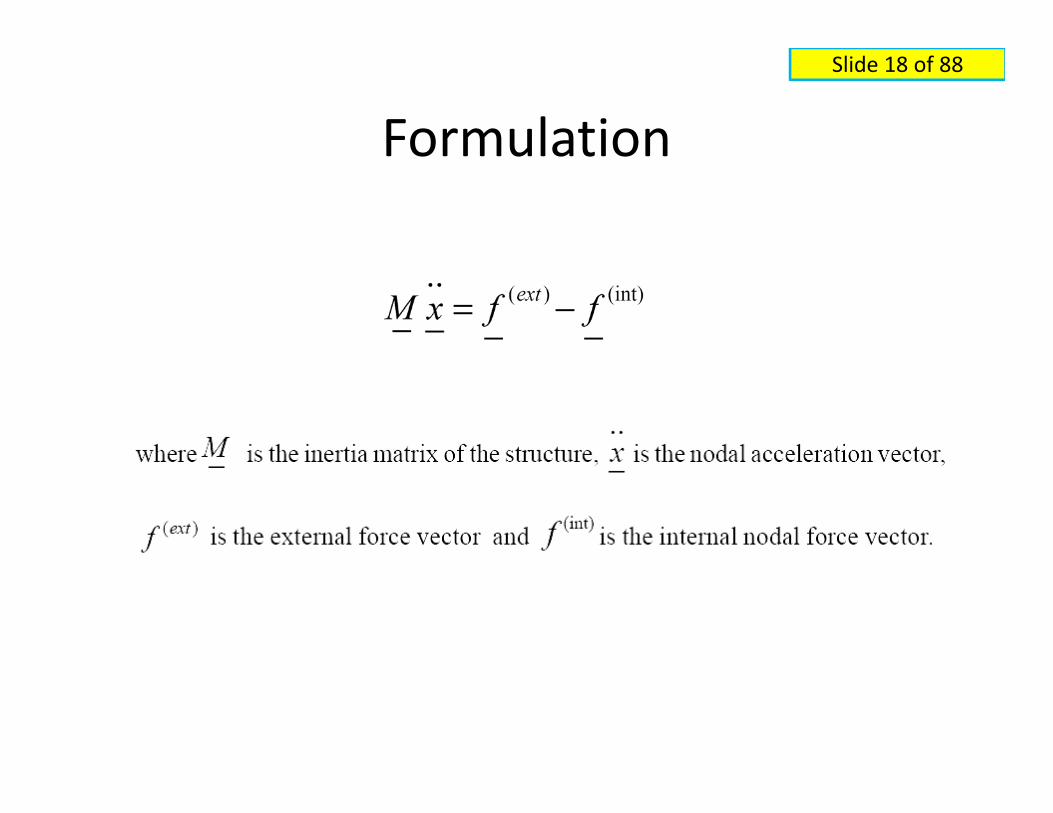
FormulationFormulation

Slide 19 of 88
FormulationFormulation
• Central difference method appliedCentral difference method applied

Slide 20 of 88
FormulationFormulation

Slide 21 of 88
FormulationFormulation
Cauchy Stress expressionCauchy Stress expression
Solution proceeds to the next step and hence for next time steptime step

Slide 22 of 88
Explicit IntegrationExplicit Integration
• Explicit integration method ‐ a numerical technique to integrate asystem of ordinary differential equations from the spatialdiscretization of a continuum
• “Explicit” refers to a specific technique whereby the equilibrium isExplicit refers to a specific technique whereby the equilibrium isexpressed at a moment in time where the displacements of allspatial points are already known
Accelerations are determined from the equilibrium– Accelerations are determined from the equilibrium– Central differencing technique allows the analyst to determine the
displacements at the next time‐step and repeat the process.• Since the displacements are known at the time for which the
dynamic equilibrium of the system is solved, this process requiresthe only inversion of the mass matrix,M.

Slide 23 of 88
Explicit IntegrationExplicit Integration• If a lumped‐mass approach is used, the mass matrix is diagonal and no
matrix inversion is necessary• If carefully implemented, explicit integration is second order accurate. It is
the element‐by‐element nature of the explicit algorithm that allows forthe best characterization of this solution technique
• Since stresses are calculated in each element separately from thecorresponding nodal displacements and/or velocities, each time‐stepsimulates the effect of the loads on one side of the element upon theopposing sides, thus representing the stress wave propagation throughthe elementh l d b k f h li i l i h h di i l bili• The only drawbacks of the explicit algorithm are the conditional stability and the clear inability of the methodology to treat static problems.

Slide 24 of 88
Conditional StabilityConditional Stability• Courant’s condition: Time‐steps determined by dividing the
l t h t i ti l th th h th ti delement characteristic length through the acoustic wave speedthrough the material of which the element is made.For typical automotive applications using mild steel elements (c=5000 m/s) with a characteristic length of 5 mm this results in an5000 m/s) with a characteristic length of 5 mm, this results in ananalysis time step of 1 microsecond.
• Analysis time‐step should not exceed the smallest of all element• The requirement is equivalent to saying that the numerical time‐The requirement is equivalent to saying that the numerical time
step of the analysis must be smaller than, or equal to, the timeneeded for the physical stress wave to cross the element.
• Due to this restriction, it is clear that explicit methods are besti d bl f h d i d h hi h l disuited to treat problems of short duration and thus, high loading
velocity and problems of a highly nonlinear nature that requiresmall time‐steps for accuracy reasons.

Slide 25 of 88
Shell ElementShell Element
• 4‐noded Belytschko and Tsay shell• Bilinearly interpolated isoparametric element, the lowest order of
interpolation functions available is used• Element is under integrated in the plane: there is a single• Element is under‐integrated in the plane: there is a single
integration point in the center of the element• Elasto‐plastic bending problems is possible by defining user‐defined
number of integration points through the thickness of the element,all placed along the element normal in the element center
• Faster to compute four under‐integrated elements than a singlep g gfully integrated element with four integration points : symmetries inthe strain‐displacement matrix that arise in the case of under‐integrated finite elementsg

Slide 26 of 88
Shell ElementShell Element
• Drawback of the under‐integration :number of zero‐genergy or hourglass modes
• Simplifications in the evaluation of the element strain‐di l t t i t i d f ti d ltdisplacement matrix, certain deformation modes resultin a zero‐strain calculation, and consequently, nostresses and nodal forces are calculated
• Nodal velocities can easily and rapidly diverge towardsinfinity as long as they remain parallel to the hourglassmodes of deformation (six in the Belytschko and Tsaymodes of deformation (six in the Belytschko and Tsayelement)
• Hourglass instability is the major drawbackHourglass instability is the major drawback

Slide 27 of 88
Shell ElementShell Element
• Hourglass instabilities prevented by the use ofHourglass instabilities prevented by the use ofperturbation hourglass resistance techniques– Detecting the presence of the hourglass mode in theelement deformation pattern, and consequently, applyingan external force field to ensure that the correspondingvelocities and/or displacements remain boundedvelocities and/or displacements remain bounded
– It cannot be stressed enough that the hourglass forcesresult from an artificial external force field and do not form
l b h h lequilibrium with stresses in the material– Consequently they remove kinetic energy from thestructure in a non‐physical waystructure in a non physical way

Slide 28 of 88
Shell ElementsShell Elements
• The element formulation and integrationThe element formulation and integration techniques are chosen in a way to optimize computational efficiencycomputational efficiency– Compromising the material stiffness in the hourglass modeshourglass modes
– Continuity of the out‐of‐plane displacement across the element boundariesac oss e e e e bou da es

Slide 29 of 88
Shell ElementShell Element• A co‐rotational local system for objectivity.• All element strains and stresses are calculated in a local
reference system following element normal and theelement 1‐2 side.
• No spurious strains and stresses are calculated if theelement is subjected to large rigid body rotational motions.
• Validity of the formulation limited to problems involvingValidity of the formulation limited to problems involvingsmall shear deformations. In practice, this is not a problemfor solving crashworthiness problems since no largemembrane shear deformations occur in sheet metal.
• It may cause hourglass modes to appear due toexaggerated rotations of the stress tensor.

Slide 30 of 88
Shell ElementShell Element• Element formulation is based on a strict uncoupling of membrane and
bending effects.• The membrane strains and stresses calculated as resulting from the loads
parallel to the local x‐y plane ‐ plane stress element.• Formulation limited to small bending strains since no thickness changes
considered.• Bending stresses result from loading along the local z‐axis and bendingg g g g
moments around the local x and y‐axes.• The bending strains in all integration points away from the element mid‐
plane are calculated using the Reissner‐Mindlin equations and thus thep g qassumption is made implicitly that the element is flat.
• All four nodes are in the same plane and a single normal is valid for theentire surface of the element.

Slide 31 of 88
Shell ElementShell Element
• Belytschko and Tsay shell element is thus the sumy yof a plane stress membrane element and aReissner‐Mindlin plate element.
• This is not valid if the element is warped• This is not valid if the element is warped.• In warped element, loads parallel to the local x‐yplane cause bending strains and these strains areplane cause bending strains and these strains aremissed by the current element formulation.
• Warped Belytschko and Tsay elements severelyd i h ’ b di iffunderestimate the structure’s bending stiffness.
• This is why this element fails the twisted beamtest often cited in the literaturetest often cited in the literature

Slide 32 of 88
Why Belytschko and Tsay ?Why Belytschko and Tsay ?• Essentially, plastic hinges develop very rapidly over the full section
f th thi ( hl 1 ) h t t l f ll d b l i id b dof the thin (roughly 1 mm) sheet metal followed by large rigid bodyrotations of the parts between the hinges.
• Objectivity of the element is thus the primary requirement, and thisis fulfilled in the element formulationis fulfilled in the element formulation.
• As long as the time for the development of the individual plastichinges is small compared to the duration of the global event, thebending stiffness plays a less important role.
• The small membrane deformation behavior and buckling behaviorof the sheet metal is in line with the assumptions of the Belytschkoand Tsay shell.T i l l b i d b bi il ll i• Triangular elements were obtained by arbitrarily collapsing two nodes of a four‐node shell element.

Slide 33 of 88
PlasticityPlasticity
• The plane stress plasticity at the individual p p yintegration points of the element is based on the membrane components of the stress tensor only
• Yield criteria• Yield criteriaσ2xx +σ2yy −σxx σyy + 3σ2xy ≤ σ2y
• Yield stress is a function of the equivalent plastic• Yield stress is a function of the equivalent plastic strain and the strain rate
• Care must be taken to account for the nature of the plastic deformation and thus a flow of the material at constant volume must be simulated.

Slide 34 of 88
PlasticityPlasticity• Usually, a Newton iteration technique involving the
unknown through‐the thickness strain in the element isperformed.
• A non‐iterative, radial return approach will lead to adeformation pattern involving a non‐zero volumetric plasticstrain.
• Poisson coefficient of the material during plasticdeformation equal to the elastic Poisson coefficient
• Computer‐time‐saving approach implemented in mostexplicit finite element codes and approximation do notp ppaffect much results of crashworthiness simulations(indication for small deformation nature of the problem)

Slide 35 of 88
Contact TreatmentContact Treatment
• All early contact algorithm implementationsAll early contact algorithm implementationswere node‐to‐segment contacts:– If the nodes and segments are on different– If the nodes and segments are on differentphysical surfaces, a so‐called master‐slave contactdefinition exists
– If they are on the same physical surface, a so‐called single surface contact definition existswhere the nodes of the surface are not permittedto penetrate the shell elements that they define

Slide 36 of 88
Contact TreatmentContact Treatment
• Contact definitions are an indispensable part ofContact definitions are an indispensable part ofthe spatial discretization of the structure
• Consist of a number of “contact springs” or springConsist of a number of contact springs or springelements that are generated in the model as soonas a penetration is detected and automaticallyas a penetration is detected and automaticallydeleted from the model as soon as that verypenetration has been annihilatedp
• Contact stiffness controlled by the user, whomultiplies this default valuewith a penalty factorp p y

Slide 37 of 88
Contact TreatmentContact Treatment
• Increase the penalty factor to avoid deep penetrations results inunrealistic simulation results
• An upper bound for stiffness required to maintain stability ofexplicit integrationexplicit integration
• A contact spring stiffness is so decided that it operates at thestability limit and will stop penetration of the slave node throughth t t i i l ti tthe master segment in a single time‐step.
• The penetration in a typical crash analysis where nodal velocitiesare of the order of 10 m/s is:
10*0.000001=0.000010m=0.01mm• Safety factor of 10 with respect to the stability does not affect
accuracy due to penetrations intrinsically allowed by contactaccuracy due to penetrations intrinsically allowed by contact

Slide 38 of 88
Contact TreatmentContact Treatment• The main problems in contact algorithms originate in the node‐to‐
t t f th d l d fi iti ll i th hsegment nature of the model definition, as well as in the searchalgorithms that define which nodes are in contact with whichsegments– Treating node‐to‐segment conditions only leads to a systematic failureTreating node to segment conditions only leads to a systematic failure
of detecting edge‐to‐edge or edge to segment penetrations.– For each slave node
• Find the nearest master nodeFi d th t t t t d t thi t d• Find the nearest master segment connected to this master node
– Works well for smooth surfaces– Not for irregular meshes and high curvatures
• The search of the nearest neighbor node is most inefficient and• The search of the nearest neighbor node is most inefficient andtime consuming part of the explicit solvers for many years, evenafter the introduction of the bucket sort algorithms

Slide 39 of 88
Contact TreatmentContact Treatment
• Early search algorithms detected a nearest master node for y geach slave node and selected a single nearest master segment from all segments connected to the nearest master nodemaster node.
• An algorithm that works very well for the simulation of the contact of two smooth convex surfaces, but fails in manycontact of two smooth convex surfaces, but fails in many situations that occur in the high curvature failure modes
• In multiple impacts and high curvatures in the mesh, as well as irregular meshes : detection of a wrong neighbor segment, allowing numerous penetrations to remain undetected.undetected.

Slide 40 of 88
Models Development Between 1987 dand 1997
• The state‐of‐the‐art model size for a full vehicle crashworthiness modelb f t f 15 f 10 000 t 150 000 l tgrew by a factor of 15, from 10,000 to 150,000 elements
• Homogeneous models to cover all load cases for frontal, side and rearimpact simulations by a single model.– Mesh size for uniform and multi‐load case model is between 5 andMesh size for uniform and multi load case model is between 5 and
10 mm.• larger than 10 mm do not provide enough accuracy• below 5 mmmake the element size smaller than the spot weld connections
A th h (b i k l t d li ) l k– Another approach (brick element modeling) also make more sense.– If the total sheet metal surface of a body‐in‐white is about 25
square meters, it is expected that model sizes between 250,000and 500,000 elements for a full body‐in‐white, y
– Limit that should sensibly be used with shell elements. (Eachelement represents between 0.5 and 1 gram of steel)

Slide 41 of 88
Models Development Between 1987 dand 1997
• Mesh is able to smoothly representDr Hannes Moeller ofthe deformed shape of the car body
• Five elements (half a wavelength)necessary to represent the width of abuckle to represent deformed
Dr. Hannes Moeller of DaimlerChrysler Corporation
buckle to represent deformedgeometry
• The simulation result remains mesh‐dependentp
• The predicted accelerations andenergy absorption will continue tochange until mesh convergence is
h dreached• This point lies between 10 and 16
elements per buckle Evolution of model size and CPU from 1988 to 1998
Table from Priya Prasad (2005)

Slide 42 of 88
Models Development Between 1987 dand 1997
• But model size is only the first half of the storyBut model size is only the first half of the story• Mesh and element quality are of utmost importance for the reliability of the result of aimportance for the reliability of the result of a crashworthiness simulationF d h i i• From a coarse and rough approximation to highly precise and a rigorous approach
• Meshing for crashworthiness has become a profession in its own right

Slide 43 of 88
Meshing processMeshing process• Every sheet metal component in the car body is meshed separately
i CAD f d tusing CAD surface data.• For a precise model of the sheet in the midplane, offsets of the
surface data are carefully performed.• The sheet is then meshed in a regular way using mesh lines that are• The sheet is then meshed in a regular way using mesh‐lines that are
as much as possible parallel and orthogonal to the incomingpressure wave and using triangles only where necessary.
• Triangles are found in areas of mesh transition or areas of highTriangles are found in areas of mesh transition or areas of highdouble curvature (warpage) only.
• At the assembly of the individual sheets, offsets may be necessaryin order to guarantee a minimum gap between all parts so that noi i i l i dinitial penetrations are generated.
• These gaps are also necessary to ensure a good performance of thecontact algorithms and avoid deep penetrations through themidplane of the opposing partmidplane of the opposing part.

Slide 44 of 88
Spot WeldsSpot Welds• Currently no clearly superior method can be distinguished• One issue is the real rotational stiffness of the spot weld• Another problem lies in the desire to make the spot weld
element location independent of the finite element meshelement location independent of the finite element mesh on both flanges.
• Flanges are currently meshed with two elements over the width, automatic generation of a regular pattern for thewidth, automatic generation of a regular pattern for the spot weld elements proves a rather elusive goal.
• In a modern vehicle model, between 3,000 and 5,000 spot welds are modeled individually and roughly in their exactwelds are modeled individually and roughly in their exact locations

Slide 45 of 88
Rubber and BoltsRubber and Bolts• More and more care is been given to modeling of the many other vehicle components
• Care must be given to the connections between car body and sub frame realized by bolts containing rubberbody and sub frame realized by bolts containing rubber bushings– rubber parts require a prohibitively fine meshnecessary to correctly account for the relative rotations– necessary to correctly account for the relative rotations between the body‐in‐white and sub‐frame
– can severely influence the acceleration response in the passenger compartmentpassenger compartment
• Rigid body connection as well as a spring element connection will both lead to erroneous results

Slide 46 of 88
Power‐TrainPower Train• Necessary to accurately model the mass, rotational inertia and center of
i i i f h i d i i bl kgravity position of the engine and transmission block.• The engine mounts modeled similar to the sub‐frame mounts.• Decisive factor in determining the relative rotation between power‐train and
body‐in‐whitebody‐in‐white.• A cylindrical shell model with 5 or 6 elements over the circumference is
typically used to model drive‐shafts in order to simulate potential contactswith brackets in the car body.
• Spherical joints connect the drive‐shafts to the wheel knuckles and to thetransmission block.
• To avoid small time‐steps, rigid body definitions are usually superimposed onthe power train subsystem modelsthe power‐train subsystem models.
• For smooth contact forces between engine block and structure, the externalgeometry of the engine block is accurately modeled using elements of a sizenot much larger then the ones used for the car bodyg y

Slide 47 of 88
AxlesAxles• Axle modeled using shell elements starting from CAD surface or line data.• For a typical McPherson front axle, this subsystem has modeling of the wheel
knuckle, suspension strut, lower control arm and stabilizer bar.• A detailed shell model to ensure that all potential contacts with structural
parts can occur in the model.• The stabilizer bar is modeled as a cylindrical bar with 5 or 6 shells over the
circumference.• If these elements have a very small dimension, mass scaling or other
techniques can be used to prevent a dramatic decrease in the calculatedstable time‐step.h bb b h h h d l d l d d l h• The rubber bushings in the chassis model are not modeled in detail, as thesub‐frame and engine mounts.
• A series of revolute, cylindrical and spherical joints provide the correct hingesbetween the chassis parts as well as between chassis and car body structurebetween the chassis parts as well as between chassis and car body structure.

Slide 48 of 88
WheelsWheels• The wheels are connected to the axle models.• The wheels consist of detailed geometrical models for
wheel rim, brake disk and outer tire.• The wheel rim and the brake disk are usually rigidlyThe wheel rim and the brake disk are usually rigidly
connected to the wheel rim, thus preventing the wheelfrom rotating.
• This must obviously be improved if mishandling simulationsThis must obviously be improved if mishandling simulationsare performed, but is acceptable for crash simulationsnecessary to account for the correct inertial response ofthe wheel.
• The wheel can become a major load path in offset oroblique frontal crash events.
• The tire stiffness must be accurately simulatedThe tire stiffness must be accurately simulated.

Slide 49 of 88
TiresTires
• The air in the tire is simulated using the airbag algorithms g g gof the explicit codes
• The pressure of a constant amount of air in the tire as a function of the compressed volume, assuming isothermal or isentropic conditions.
• A remaining problem is in the material model of the tires• A remaining problem is in the material model of the tires themselves.
• Existing tire models are far too complex to be incorporated in full vehicle crash models, and research is needed to generate reasonable and efficient approximations.

Slide 50 of 88
Steering AssemblySteering Assembly• The steering rack and its connections to the wheel knuckle modeled
i il t th f t d lsimilar to the front and rear axles.• A correct modeling of outer contours releasing the correct degrees
of freedom in the connections using joint and/or spring elements is usually considered sufficientusually considered sufficient.
• A detailed model is built that couples the translational motion of the steering rack to the rotation of the wheels in the study of frontal offset and oblique impacts.
• Very often, a steering rack model that is fixed to the sub‐frame structure is used, thus effectively blocking the wheel rotation.
• The steering column is usually modeled as a set of cylindrical tubes lidi i h hsliding in each other.
• It is this sliding motion that simulates the telescopic deformation of the steering column as the dummy hits the steering wheel.

Slide 51 of 88
Engine sectionEngine section• Engine motion is crucial for the dummy response in the passenger
compartment during a frontal impactcompartment during a frontal impact.• Engine motion is at least partly determined by contacts with the structure
and other components located under the hood.• Components include the battery, radiator, air conditioning unit, automatic p y, , g ,
braking system unit, ventilators and electro‐engines at the radiator, radiator bracket and light brackets.
• Some of these are mild steel structures and can be modeled as such.• Others are hard points and little care must be given to the determination• Others are hard points and little care must be given to the determination
of their stiffness as long as the resulting strength is considerably higher than that of the surrounding structural parts.
• An exception is the radiator model, which must crush under the impact of h i bl k d h d i l ithe engine block and somewhat damp its acceleration response.
• Equivalent models based on force‐displacement curves determined in a drop test

Slide 52 of 88
DoorsDoors• Structural model of the doors sufficient for the simulation of frontal and
rear crashesrear crashes• For side impact load cases, door inner components must be carefully
modeled.• Hinges and locks must be modeled in such a way that the correctg y
rotational degrees of freedom are released between the door model andthe model of the body‐in‐white.
• Door structures are mostly quite weak with respect to bending.• The inner components such as guide rails for the window electrical• The inner components such as guide rails for the window, electrical
motors, loudspeakers and the window glass provide the flexural stiffnessof the entire component, and thus, determine the critical timing of theimpact between door and occupant.h i i l f h d i i i d i i h• The inertial response of the door structure is important in determining thevelocity of impact with the dummy.
• The mass of the door as well as the masses of its individual componentsshould be carefully checked.y

Slide 53 of 88
Rest of car modelRest of car model• Windshield and bumper are modeled in frontal impact, whereas the fuel tank and spare wheel and tire are typically present in rear impact models.
• The instrument panel may be required for theThe instrument panel may be required for the simulation of frontal and side impact and the front seats are essential in all models.
• Roughly 50 to 60 percent of the total vehicle mass is• Roughly 50 to 60 percent of the total vehicle mass is modeled and a careful mass check is typically performed at this stage. Th i i d d l ll dd d• The remaining masses are traced and locally added to the model as density increases and/or nodal added masses

Slide 54 of 88
Software Development Between 1987 dand 1997
• Modeling technology has evolved towards ever larger and mored t il d i l d l f th hi l i t fdetailed numerical models of the vehicle in a quest for moreaccuracy and more reliability in the results.
• Software development trying to run and manage these models withcontinuously increasing size using essentially the same basiccontinuously increasing size, using essentially the same basictechnology.
• A first important focus point of development was on animationpackages for rapid post‐processing for visualization of the simulatedcrash event and the deformation modes of the car body and fordisplay of plastic strain, stresses and energy densities over theindividual parts.
• This allowed the engineer to immediately identify those• This allowed the engineer to immediately identify thosecomponents that absorb more or less energy
• Interactive pre‐processing software of the models to quicklyincorporate structural changesp g

Slide 55 of 88
Software Development Between 1987 dand 1997
• Effort has been to increase the efficiency of the solvers• Explicit finite element codes have been optimized to the point that they
run in a 99 percent Vectorized mode.• The element‐by‐element nature of the codes lends itself particularly well
for Vectorized processing considering the nodal force assembly, and thep g g y,search algorithms in the contact‐impact routines.
• Parallelization of the codes achieving ever better scaling performance onboth shared memory and distributed memory machines.
• A major advance was the replacement of node based contact search• A major advance was the replacement of node‐based contact searchalgorithms by so‐called segment‐based search algorithms.
• The old algorithms based on the search of a nearest master node for everyslave node are always computer‐time consuming even if bucket sortingi hi i iimproves this situation.
• With the new segment‐based search methods, an algorithm wasintroduced that is not only computationally much more efficient, but alsoimproves on many of the shortcomings of older algorithms.p y g g

Slide 56 of 88
Software Development Between 1987 dand 1997
• Techniques developed in order to allow explicit simulations to run with aconstant time step valueconstant time‐step value.
• The stable time step of the analysis is linearly dependent upon the shortestmesh dimension in the model.
• As deformation changes (reduces) this dimension, a drop of the time‐steph i ll id blseems mathematically unavoidable.
• Indeed it is not possible to keep a constant time‐step during a crashsimulation with highly deforming shell elements without changing the physicsof the problem.
• Small strain formulations where the influence of the change in geometry uponthe element stiffness is ignored from a certain point on (or during the entireanalysis), to a controlled reduction of the material’s elastic modulus as itplastically deforms.
• The most widely used method is mass scaling.• As an element dimension decreases, the corresponding material density or
nodal masses are increased in such a way that the resulting time step remainsconstant.co sta t

Slide 57 of 88
Software Development Between 1987 dand 1997
• The basic technology of explicit finite element codes samed h l d dduring the last decade.
• One of the major improvements in accuracy was thereplacement of degenerated quadrilateral elements by a trueC0 t i l l t d b B l t hkC0 triangle element as proposed by Belytschko.
• This element is free of hourglass modes and has a bendingresponse equivalent to the flat quadrilateral Belytschko andTsa elementTsay element.
• Major improvement with respect to a degenerated quad butstill must be used with care and in limited numbers mainlybecausebecause• in‐plane shear stiffness that can be too high in certain cases

Slide 58 of 88
Software Development Between 1987 dand 1997
• A large number of special purpose options were addedto the codes in order to fulfill crash‐specific functionsin the models.– Such as rigid bodies, but spring elements, spot weldg , p g , pelements, joint elements and occupant simulationoriented options such as seatbelt, and airbag models.
• These mainly improve the application scope of theese a y p o e e app ca o scope o ecodes.
• It seems that the simulations have arrived at acrossover point where the factor limiting the accuracycrossover point where the factor limiting the accuracyof the simulation is no longer the mesh, but rather, thenumerical algorithms that are used in the explicit finiteelement codeselement codes.

Slide 59 of 88
Limitations of Current TechnologyLimitations of Current Technology
• Any finite element simulation activity can be seeny te e e e t s u at o act ty ca be seeas a chain with two links.– The first link is the numerical model, essentially ahyper‐complicated mass‐spring system whosedynamic behavior is an approximation of thecontinuum (the car) that is to be modeled.( )
– The second link is the software or the numericalalgorithm to perform a numerical time integration ofthe system of ordinary differential equationsthe system of ordinary differential equations
• The solution obtained on the computer is anapproximation of the correct (analytical) solutionapproximation of the correct (analytical) solution
Slide 60 of 88
Limitations of Current TechnologyLimitations of Current Technology• The main problem with early simulation work was clearly
the coarseness of the shell element mesh representing thecar body.
• This resulted in simulation of the low curvature (highwavelength) buckling modes only, and thus constantlyoverestimated the energy absorption in the structure sincehigh curvature modes were precluded from the simulationb th tl f th hby the outlay of the mesh.
• Too coarse meshes generally resulted in too stiff behaviorof the energy absorbing, highly deforming structural parts.
• The weak link in the chain was clearly the mode, and anyadditional loss of accuracy due to the use of very simplealgorithms was almost welcome.

Slide 61 of 88
Algorithms – weak linkAlgorithms weak link• Some of the algorithmic deficiencies tended to compensate for the
d t th f th fi it l t herrors due to the coarseness of the finite element mesh.– Penetrations allowed due to failing contact algorithms and zero energy
modes in under‐integrated shell elements• Greater potential for improvement in the near future lies in the useGreater potential for improvement in the near future lies in the use
of more accurate algorithms rather than in further refinement ofthe models.
• In other words, the algorithms have become the weak link in thegchain.
• Improved algorithms for shells and contacts have been available inexplicit codes for quite a while, but have not been used extensivelyfor a variety of reasons including increased computer time and lackfor a variety of reasons, including increased computer time and lackof numerical robustness.

Slide 62 of 88
Edge to Edge penetrationsEdge to Edge penetrations• Approximately half of all numerical problems in modern crashworthiness
analysis are caused by edge to edge penetrationsanalysis are caused by edge‐to‐edge penetrations.• The complex surfaces with high double curvature are discretized by large finite
elements, resulting in a polygonal surface with lots of links and edges.• Edge‐to‐edge penetrations can go undetected since they cause no nodal
i h h f hpenetrations through any of the segments.• It makes the model less stiff than the actual structure where no penetrations
can occur.• Consequent movements of the penetrated segments can easily lead impactsq p g y p
of nodes on segments ‘from the wrong side.’• Su‐anomalies in the models will lead to local instabilities, hour‐glassing due to
the extreme out‐of‐plane loads and potentially abort the simulationprematurely.p y
• Classical contact algorithms set the tangled nodes free and allow penetrationwithout any further checks resulting in a further loss of realism.
• Edge‐to‐edge algorithms are currently being introduced into all commercialexplicit finite element codesexplicit finite element codes.

Slide 63 of 88
Hour‐glassHour glass• Increasingly finer models allows for detection of the influence of
th d d th di t b tithe zero‐energy modes and the corresponding perturbationhourglass forces in the numerical models.
• The perturbation hourglass forces are nodal forces introducednumerically in order to prevent the hourglass velocity componentsnumerically in order to prevent the hourglass velocity componentsin the element from becoming unbounded.
• Although these forces are supposed to make up for the missingelement stiffness, they do not correspond to a stress in theelement, and thus constitute an external force field of ratherarbitrary magnitude controlled by user‐defined coefficients.
• Due to the introduction of this force field, a perturbation‐stabilizedunder integrated element may behave both too weak or too stiffunder‐integrated element may behave both too weak or too stiffcompared to reality.

Slide 64 of 88
Integration pointsIntegration points• Full integration using four‐Gauss integration points in the element of the
bilinearly interpolated elementbilinearly interpolated element.• Unfortunately, straightforward solution does not work.• Fully under‐integrated elements with uniform bilinear interpolation suffer
from another drawback called “shear locking”.g• Shear locking occurs when non‐zero out‐of‐plane shear strains are
predicted by the element in conditions of pure bending resulting in anoverly‐stiff element response.
• This problem is caused by uniform interpolation: if out of plane• This problem is caused by uniform interpolation: if out‐of‐planedeflections are interpolated with higher order rather then bilinearfunctions, formulations that exhibit no shear locking are possible.
• However, complexity increases which decreases element performance.• Development of a fully‐integrated element that avoids all shear locking
and maintains the simplicity of uniform bilinear interpolation has provento be a challenging task.

Slide 65 of 88
Selective Reduced IntegrationSelective Reduced Integration• Several solutions exist to neutralize hourglass modes using uniform bilinear interpolation while avoiding shear locking.
• A first possibility is the selective reduced‐integrationA first possibility is the selective reduced integration (SRI) elements.
• This solution consists of performing a full integration for the membrane and bending strains combined withfor the membrane and bending strains combined with a reduced integration for the out‐of‐plane shear strains. Th l ff i l id h l ki f• These elements effectively avoid shear locking for rectangular elements but some problems still occur in irregular meshes

Slide 66 of 88
ANS elementsANS elements• Assumed‐natural‐coordinate‐strain (ANS) elements.
I i di fi ld i l diff i d b i d• Isoparametric coordinate field is no longer differentiated, but improvedestimates of the out‐of‐plane shear strain field are used directly.
• This approach leads to a formulation without shear locking independently ofthe quadrature rule used and both reduced integration and full integrationi l i i i i l li i fi i l dimplementations exist in most commercial explicit finite element codes.
• A reduced integration ANS element does not solve the original hourglassproblem and would not suffer from shear locking.
• The advantage of the ANS approach for these elements lies in the improvedg pp paccuracy obtained in irregular meshes.
• In particular, the ANS element passes the Kichhoff patch test, whereaselements with classical quadrature of the shear strains always fail this ratherelementary requirement.y q
• A very efficient fully‐integrated ANS element exists in the LS‐DYNA code,which overcomes all hour‐glassing and shear locking problems at a cost ofroughly three times the original Belytschko and Tsay shell element

Slide 67 of 88
ANS – contd..ANS contd..• If full integration is still perceived as not efficient enough to allow
t i t di l l h thi d l fparametric studies on large‐scale crashworthiness models ofvehicles, a more economical approach may be given by physicalstabilization.
• Here under‐integrated versions (preferably of the ANS element) areHere, under integrated versions (preferably of the ANS element) areused and an approximate analytical integration is performed overthe element of the non‐constant part of the strain
• The constitutive law is invoked in order to estimate hourglassstresses resulting in a set of nodal forces that are supposed tocorrect missing stiffness components of the element rather exactly.
• This approach is much more efficient than full‐ or reduced‐selectiveintegration and requires only about 30 percent more computerintegration and requires only about 30 percent more computertime then the original Belytschko and Tsay element. The elementalso passes the Kichhoff patch test

Slide 68 of 88
Flat GeometriesFlat Geometries• Next to the existence of zero‐energy modes, a second potential problem is
its limitation to flat geometries.• The use of the Mindlin plate theory where the fiber direction is assumed
to coincide with the normal to the plate surface.• In warped elements, bending strain can be underestimated for two
reasons.– Rotations normal to the element will not cause any curvature to be calculated although
these rotations may not be parallel to the nodal drill degrees of freedom (fiber direction) in all nodes of the element.
– Force loads in the element plane should also cause bending strains in a warped element and will fail to do so when the unmodified Belytschko and Tsay element is used.y y
• Those effects will lead to the failure of the so‐called twisted beam test by this element.

Slide 69 of 88
Software issues ‐ conclusionSoftware issues conclusion
• It should be emphasized strongly that none of the improvementsdescribed above affect the original assumption that only smalldeformations exist within a single shell element.
• These improvements are merely meant to correct someThese improvements are merely meant to correct somedeficiencies of the element formulations within this framework.
• Thus, the use of more sophisticated elements does not allow thef huse of coarser meshes.
• All rules developed earlier to determine mesh density of acrashworthiness model still apply.
• A good crashworthiness simulation can only be obtained if themesh is able to smoothly represent the deformed geometry of thecar body.y

Applications of FEApplications of FE

Slide 71 of 88
Component ModelsComponent Models• Components are typically
t t d i b th i t ti dtested in both quasi‐static anddynamic modes
• DynamicDrop silo : Component is fixed– Drop silo : Component is fixedto the ground on a load celland loading is typically appliedfrom the gravitational fall of arigid mass onto the free end ofrigid mass onto the free end ofthe component.
– Sled test: Component mountedhorizontally onto the sledwhich subsequently is launched
Rail test set‐up – Sled Test
which subsequently is launchedto impact a rigid or deformablesurface with the componentmaking first contact.
Figure from Priya Prasad (2005)

Slide 72 of 88
Component ModelsComponent Models• The rail deformations exhibited
two plastic hinges at the rail Rail responsetwo plastic hinges at the rail curvatures, rotation at the free end and plastic hinge at the fixed end.
k f d h
p
• peak force increased with impact speed from 50 to 60 kPa, due to strain rate effects of the material
• The FE simulation corresponding p gto 8.2 m/s impact agreed quite well with the test result when the strain rate effects were included in the simulation.
• Increasing the number of shell elements from 2,000 to 3,000 showed minor influence on the overall response S‐rail final deformations Initial impact overall response
speeds of 2, 4.5 and 8.2 m/s into a rigid wall.
Figure from Priya Prasad (2005)

Slide 73 of 88
Component ModelsComponent ModelsMeasured and FE‐calculated forces
Mid Rail deformations
M d d FE l l t d f t• Measured and FE‐calculated forces agreement• Like the S‐rail response, the peak force increased with increasing the impact speed due to strain rate effects.
Figure from Priya Prasad (2005)

Slide 74 of 88
Substructure ModelsSubstructure Models
• Impact speed was 13.4 m/s.• In this simulation, no strain rate effects were included in theanalysis since the mid‐rails were manufactured from high strengthsteel, which typically exhibits little strain rate effects
Table from Priya Prasad (2005)

Slide 75 of 88
Full‐scale vehicle structure modelsFull scale vehicle structure models
• Evolution of the modelsEvolution of the models in size and complexity since 1980s
• Detail modeling of vehicle structures an integral step in the vehicle design processff• Offset impact
requirements
Ford Taurus model (2001) has over 1.5 Million elementsTable from Priya Prasad (2005)

Slide 76 of 88
An example modelAn example model• Approx. 10 mm x 10 mm shell elements in front structure for plastic hinges and buckling
• The engine and transmission simulated by rigid shell elements, representing the mass and moments ofelements, representing the mass and moments of inertia at the engine’s CG location
• Coarser mesh for structure behind dash panelTh di t i lid l t• The radiator using solid elements
• Two front doors included with hinges• The rear doors were excludedThe rear doors were excluded• An instrument panel was also included along with appropriate structures for knee restraint.

Slide 77 of 88
An example modelAn example modelModel Statistics: Contact Definitions• 61,500 shell elements• 500 solid elements• 25 beam elements• 1 200 spot welds
• A rigid wall in front of the vehicle with stick condition.
• Automatic contact surfaces were defined in six zones as follows:• 1,200 spot welds
• 15 joints• 40 concentrated nodal masses• 10 springs
– Front‐left corner (up to front body hinge pillar)
– Front‐right corner (up to front body hinge pillar)10 springs
• 200 parts• 66,000 nodes
– Front‐center (include up to the middle of the engine)
– Rear‐center (from middle of the engine to the fire wall)
– Driver side centre‐pillar to door– Passenger side centre‐pillar to door

Slide 78 of 88
ResultsResults• CRAY Y‐MP8E system.• Time step was approximately 0.7 ¼s• A 100 ms simulation was completed in
about 45 hours on one processor.• Was necessary to refine the radiator The initial (at timey
model for severe hour‐glassing• Intermediate vehicle configurations
(not shown) exhibited realisticsequential deformations as seen in
The initial (at time0) and final (at100 ms) vehicledeformed shapesq
high‐speed film analysis of barriercrashes.
• Time histories of the global energybalance, velocity at the front rocker,, y ,and barrier force provided veryreasonable results, comparable to testdata
Initial impact velocity 13.4 m/sFigure from Priya Prasad (2005)

Slide 79 of 88
Integrated Vehicle‐Occupant‐d lRestraints Model
• Attempts have been made to couple occupantAttempts have been made to couple occupant and structural codes
• Conceptually all FE codes can accomplish this• Conceptually, all FE codes can accomplish this task, since rigid body equations of motion are a special case of the FE formulationa special case of the FE formulation
• Several codes were developed, most i di i i l dprominent discussions on one single code was
from Ove‐Arup, Schelkle and Remensperger.

Slide 80 of 88
Khalil and Sheh modelKhalil and Sheh model• Vehicle including a body‐in‐
hit t t f f dModel statistics:
white structure of a four‐door passenger sedan,
• Engine, transmission, etc., weighing 1 750 kg
• 70,000 shell elements• 9,000 solid elements• 300 beam elementsweighing 1,750 kg,
• Bucket car seat structure with the seat cushion,
• Energy absorbing steering
• 1,300 spot welds• 300 parts• 91,000 nodesEnergy absorbing steering
column with a steering wheel and folded air bag,
• Instrument panel, including a d i id k b l
• 20 contact segments
driver side knee bolster,• Door structure, and• Hybrid III dummy
Figure from Priya Prasad (2005)

Slide 81 of 88
Khalil and Sheh modelKhalil and Sheh model
Total energy remainedThe velocity trace agreed quite well with Total energy remainedapproximately constant throughoutthe 100 ms duration
The velocity trace agreed quite well with test data, particularly at the point where the vehicle velocity crosses the zero line
Figure from Priya Prasad (2005)

Slide 82 of 88
Khalil and Sheh modelKhalil and Sheh model• The pulse shape with its
two peaks and the times atwhich they occurred isconsistent withexperimental data.
• The first peak force almostcoincided with the resultscoincided with the resultsobtained from one test.
• However, the second peakwas only 60 percent of thewas only 60 percent of thetest value due to inexactmodeling of the engine‐to‐dash panel interactionsdash panel interactions. Barrier unfiltered force‐time pulse
Figure from Priya Prasad (2005)

Slide 83 of 88
NCAP tests ( 35mph)NCAP tests ( 35mph)
NCAP test – 0 ms NCAP test – 100 msNCAP test – 0 ms NCAP test – 100 ms
Full rigid barrier Vehicle + Dummy(HIII)
Figure from Priya Prasad (2005)

Slide 84 of 88
Pole Impact – 30mphPole Impact 30mph
Pole impact (initial) Pole Impact (after 100ms)Pole impact (initial) Pole Impact (after 100ms)
Requires a detailed FE modelFE model
Figure from Priya Prasad (2005)

Slide 85 of 88
Offset test 30 mphOffset test 30 mph
Initial FinalInitial Final
Requires a detailed FE model
Figure from Priya Prasad (2005)

Slide 86 of 88
Summary of simulationsSummary of simulations
Difference in frontal deformations corresponding to the previous four impactscenariosscenarios
Frontal vehicle deformations Figure from Priya Prasad (2005)

Slide 87 of 88
ConclusionsConclusions• Although the FE technology for structural mechanicswas introduced in the early sixties, it took about 25years of additional development to apply it successfullyto crashworthiness simulation of automobilestructures.
• The developments were mainly in nonlinear problemformulation of shell elements, reduced spatialformulation of shell elements, reduced spatialintegration, explicit time integration, plasticity, andcontact‐impact treatments.
• The role of super computers and code vectorization• The role of super computers and code vectorizationwas indeed indispensable for the development of full‐scale vehicle models.

Slide 88 of 88
ConclusionsConclusions
• The mid‐eighties to the mid‐nineties time span can beThe mid eighties to the mid nineties time span can becharacterized as the renaissance period of FEcrashworthiness models.
• Generic and actual components of vehicle structures aswell as full‐scale vehicle models were developed toi l t f t l id hi l i t ith b isimulate frontal, side, rear vehicle impact with barriers.
• Vehicle‐to‐vehicle collisions were also developed andanalyzed In addition to vehicle structural modelinganalyzed. In addition to vehicle structural modeling,dummy and air bag models were created and theirresponses were validated against experimental datap g p

Slide 89 of 88
ConclusionsConclusions
• In 1995, a process was established to integrate vehicleIn 1995, a process was established to integrate vehiclestructure, instrument panel, steering assembly, driverair bag and Hybrid III dummy models in a single FEmodel.
• This process centered on integrating existingt d b t d l d l lcomponents and subsystem models and clearly
demonstrated that explicit FE technology can simulateboth structural and restrained occupant responseboth structural and restrained occupant responseresulting from a vehicle crash in a single integratedmodel, although the results are preliminary.


