
Finite Element Analysis of Particulate composite embedded ... · PDF fileperformed on...
7
International Research Journal of Engineering and Technology (IRJET) e-ISSN: 2395-0056 Volume: 02 Issue: 04 | July-2015 www.irjet.net p-ISSN: 2395-0072 © 2015, IRJET.NET- All Rights Reserved Page 649 Finite Element Analysis of Particulate composite embedded in Fibrous Composite Layer Nikhil J.Chaudhari 1 A.S.Rao 2 Vinaay Patil 3 1 Post Graduate Student, 2 Asst. Professor Department of Mechanical Engineering Veermata Jijabai Technological Institute Mumbai, India 3 Manager, Vaftsy CAE, Pune, India ---------------------------------------------------------------------***--------------------------------------------------------------------- Abstract - Composite can be defined as a structural material consisting two or more combined constituents that are combined at a macroscopic level and are not soluble in each other. In order to improve the properties of existing composites, a newer trend is towards the development of combination of one or more types of Composites together to form hybrid structure. Generally this combination of fibre composites by inclusion of particulate composite layers applies to advanced composites and refers to use of various combinations of fibers or particulate in matrices. They have unique feature that can be used to meet the diverse and competing design requirements in a more cost effective way than either advanced or conventional composites. This paper devoted to fiber Reinforcement is the requirements of certain application can be achieved not only by sizing the cross sectional areas and thickness of components but by changing the material system design i.e. optimizing the material system itself such as fiber orientation angle. The optimization techniques are being used to assist the designer in finding an optimized solution. Key Words: Composites, Finite Element analysis, ANSYS, Optimization, Fibre orientation. 1. INTRODUCTION By inclusion of particulate composite layers in fibre composite flexibility as compared to other reinforced composites. Normally it contains a high modulus fiber with low modulus Particles. The high-modulus fiber provides the stiffness and load bearing qualities, whereas the low-modulus particles make the composite more damage tolerant and keeps the material cost low. It also helps to reduce weight without sacrificing strength and improves electrical and thermal characteristics of the composite material. The mechanical properties of a hybrid composite can be varied by changing volume ratio and stacking sequence of different plies. De-lamination is major problem which is observed in fibre reinforced composite is reduced by including particulate composite layers because of increasing adhesion forces between consecutive layers of the composite. This paper is explains modeling the composite laminate. And also proposes a methodology to model a composite laminate with a composite material to analyze its stress, Strength and stiffness using ANSYS software. In order to evaluate the effectiveness of composite, stress analysis is performed on composite using ANSYS. In this work effort is made to find out optimum angle of fibre which gives reduced stress levels so that advantage of ultimate weight reduction along with stresses can be obtained. 2. MATERIALS AND METHOD Composite model is created using ANSYS workbench. Model is consisting of various layers of particulate composite along with the fibrous composite. Cylindrical rods are taken as a fibre and ellipsoidal particulate is taken as particle reinforcement which is embedded in to matrix material. Alternate layers of particulate and fibre layer is stacked one above other. By using add frozen operation in extrude is created which helps to create contact non-linearity between matrix and reinforcement. 2.1 Properties of material Table -1: Properties of Material Material Properties Matrix Material (Epoxy Resin) Reinforcing Fibers (Carbon Fibre) Particulate Material (Glass Fibre) Young's Modulus in X,Y & Z direction (GPa) 183 239.35 2.3 Poisson’s Ratio PRXY 0.3 0.3 0.41 Poisson’s Ratio PRYZ 0.3 0.3 0.41 Poisson’s Ratio PRXZ 0.3 0.3 0.41
-
Upload
nguyenminh -
Category
Documents
-
view
216 -
download
2
Transcript of Finite Element Analysis of Particulate composite embedded ... · PDF fileperformed on...

International Research Journal of Engineering and Technology (IRJET) e-ISSN: 2395-0056
Volume: 02 Issue: 04 | July-2015 www.irjet.net p-ISSN: 2395-0072
© 2015, IRJET.NET- All Rights Reserved Page 649
Finite Element Analysis of Particulate composite embedded in Fibrous
Composite Layer
Nikhil J.Chaudhari 1 A.S.Rao 2 Vinaay Patil 3
1Post Graduate Student, 2Asst. Professor Department of Mechanical Engineering Veermata Jijabai Technological Institute
Mumbai, India 3 Manager, Vaftsy CAE, Pune, India
---------------------------------------------------------------------***---------------------------------------------------------------------Abstract - Composite can be defined as a structural
material consisting two or more combined constituents that
are combined at a macroscopic level and are not soluble in
each other. In order to improve the properties of existing
composites, a newer trend is towards the development of
combination of one or more types of Composites together to
form hybrid structure. Generally this combination of fibre
composites by inclusion of particulate composite layers
applies to advanced composites and refers to use of various
combinations of fibers or particulate in matrices. They have
unique feature that can be used to meet the diverse and
competing design requirements in a more cost effective way
than either advanced or conventional composites. This
paper devoted to fiber Reinforcement is the requirements
of certain application can be achieved not only by sizing the
cross sectional areas and thickness of components but by
changing the material system design i.e. optimizing the
material system itself such as fiber orientation angle. The
optimization techniques are being used to assist the
designer in finding an optimized solution.
Key Words: Composites, Finite Element analysis,
ANSYS, Optimization, Fibre orientation.
1. INTRODUCTION By inclusion of particulate composite layers in fibre composite flexibility as compared to other reinforced composites. Normally it contains a high modulus fiber with low modulus Particles. The high-modulus fiber provides the stiffness and load bearing qualities, whereas the low-modulus particles make the composite more damage tolerant and keeps the material cost low. It also helps to reduce weight without sacrificing strength and improves electrical and thermal characteristics of the composite material. The mechanical properties of a hybrid composite can be varied by changing volume ratio and stacking sequence of different plies. De-lamination is major problem which is observed in fibre reinforced composite is reduced by including particulate composite layers because of increasing adhesion forces between consecutive layers of the composite.
This paper is explains modeling the composite laminate. And also proposes a methodology to model a composite laminate with a composite material to analyze its stress, Strength and stiffness using ANSYS software. In order to evaluate the effectiveness of composite, stress analysis is performed on composite using ANSYS. In this work effort is made to find out optimum angle of fibre which gives reduced stress levels so that advantage of ultimate weight reduction along with stresses can be obtained.
2. MATERIALS AND METHOD Composite model is created using ANSYS workbench. Model is consisting of various layers of particulate composite along with the fibrous composite. Cylindrical rods are taken as a fibre and ellipsoidal particulate is taken as particle reinforcement which is embedded in to matrix material. Alternate layers of particulate and fibre layer is stacked one above other. By using add frozen operation in extrude is created which helps to create contact non-linearity between matrix and reinforcement.
2.1 Properties of material Table -1: Properties of Material
Material Properties
Matrix Material (Epoxy Resin)
Reinforcing Fibers
(Carbon Fibre)
Particulate Material
(Glass Fibre)
Young's Modulus in X,Y & Z direction (GPa)
183 239.35 2.3
Poisson’s Ratio PRXY
0.3 0.3 0.41
Poisson’s Ratio PRYZ
0.3 0.3 0.41
Poisson’s Ratio PRXZ
0.3 0.3 0.41
International Research Journal of Engineering and Technology (IRJET) e-ISSN: 2395-0056
Volume: 02 Issue: 04 | July-2015 www.irjet.net p-ISSN: 2395-0072
© 2015, IRJET.NET- All Rights Reserved Page 650
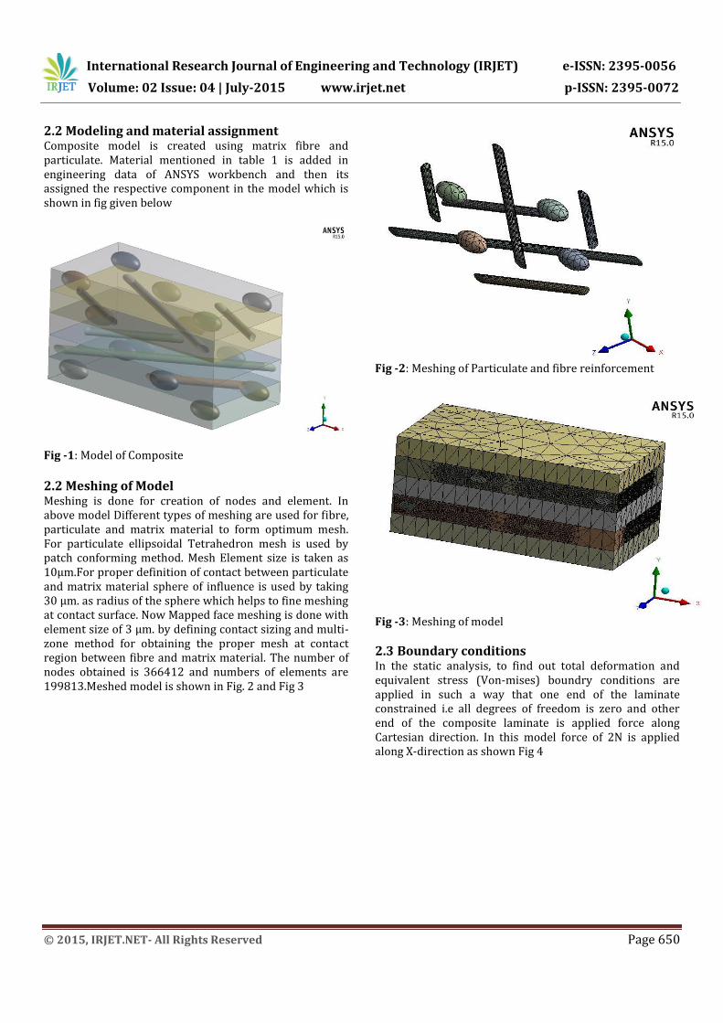
2.2 Modeling and material assignment Composite model is created using matrix fibre and particulate. Material mentioned in table 1 is added in engineering data of ANSYS workbench and then its assigned the respective component in the model which is shown in fig given below
Fig -1: Model of Composite
2.2 Meshing of Model Meshing is done for creation of nodes and element. In above model Different types of meshing are used for fibre, particulate and matrix material to form optimum mesh. For particulate ellipsoidal Tetrahedron mesh is used by patch conforming method. Mesh Element size is taken as 10µm.For proper definition of contact between particulate and matrix material sphere of influence is used by taking 30 µm. as radius of the sphere which helps to fine meshing at contact surface. Now Mapped face meshing is done with element size of 3 µm. by defining contact sizing and multi-zone method for obtaining the proper mesh at contact region between fibre and matrix material. The number of nodes obtained is 366412 and numbers of elements are 199813.Meshed model is shown in Fig. 2 and Fig 3
Fig -2: Meshing of Particulate and fibre reinforcement
Fig -3: Meshing of model
2.3 Boundary conditions In the static analysis, to find out total deformation and equivalent stress (Von-mises) boundry conditions are applied in such a way that one end of the laminate constrained i.e all degrees of freedom is zero and other end of the composite laminate is applied force along Cartesian direction. In this model force of 2N is applied along X-direction as shown Fig 4

International Research Journal of Engineering and Technology (IRJET) e-ISSN: 2395-0056
Volume: 02 Issue: 04 | July-2015 www.irjet.net p-ISSN: 2395-0072
© 2015, IRJET.NET- All Rights Reserved Page 651
Fig -4: Boundary condition of Composite along X-direction
2.4 Solution After applying boundary conditions solution is simulated for Deformation and Equivalent (von-mises) of all the components associated with the model. It is done for all layers and its reinforcement element. Various plots of deformation of whole composite and Equivalent (von-mises) for each component in the model is shown below.
Fig -5: Deformation& Equivalent (Von-mises) stress plots
2.4.1 Plots for Layer 1 Fig 5 shows deformation and stress plot for complete composite structure. Now stress plots for various elliptical particulate and fibre as per layer of composite as shown in figs given below.
(a) (b)
(c) (d)
(e)
Fig -6:(a-e) Equivalent (Von-mises) stress plots for (Particulate) Layer 1
International Research Journal of Engineering and Technology (IRJET) e-ISSN: 2395-0056
Volume: 02 Issue: 04 | July-2015 www.irjet.net p-ISSN: 2395-0072
© 2015, IRJET.NET- All Rights Reserved Page 652
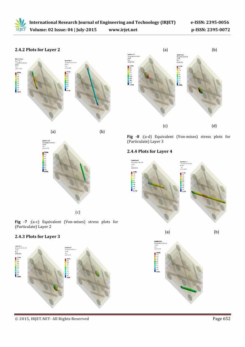
2.4.2 Plots for Layer 2
(a) (b)
(c)
Fig -7 :(a-c) Equivalent (Von-mises) stress plots for (Particulate) Layer 2
2.4.3 Plots for Layer 3
(a) (b)
(c) (d) Fig -8 :(a-d) Equivalent (Von-mises) stress plots for (Particulate) Layer 3
2.4.4 Plots for Layer 4
(a) (b)
International Research Journal of Engineering and Technology (IRJET) e-ISSN: 2395-0056
Volume: 02 Issue: 04 | July-2015 www.irjet.net p-ISSN: 2395-0072
© 2015, IRJET.NET- All Rights Reserved Page 653
(c)
Fig -9 :(a-c) Equivalent (Von-mises) stress plots for (Particulate) Layer 4
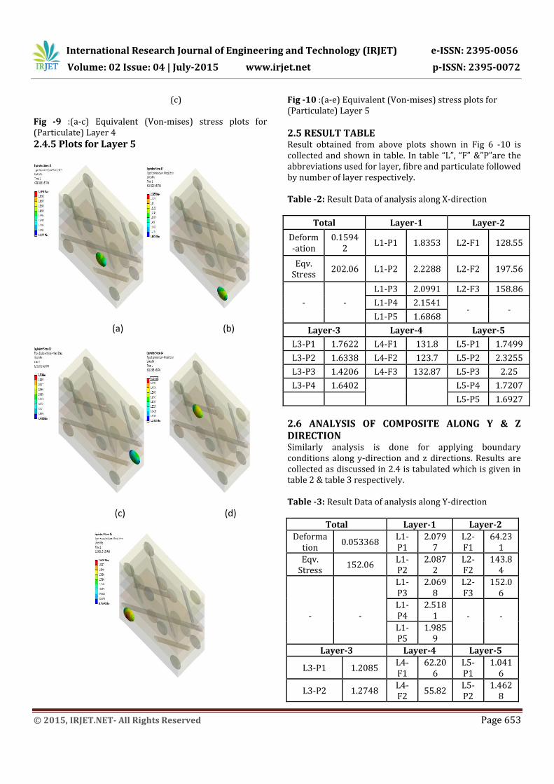
2.4.5 Plots for Layer 5
(a) (b)
(c) (d)
Fig -10 :(a-e) Equivalent (Von-mises) stress plots for (Particulate) Layer 5
2.5 RESULT TABLE Result obtained from above plots shown in Fig 6 -10 is collected and shown in table. In table “L”, “F” &”P”are the abbreviations used for layer, fibre and particulate followed by number of layer respectively. Table -2: Result Data of analysis along X-direction
Total Layer-1 Layer-2
Deform-ation
0.15942
L1-P1 1.8353 L2-F1 128.55
Eqv. Stress
202.06 L1-P2 2.2288 L2-F2 197.56
- -
L1-P3 2.0991 L2-F3 158.86
L1-P4 2.1541 - -
L1-P5 1.6868
Layer-3 Layer-4 Layer-5
L3-P1 1.7622 L4-F1 131.8 L5-P1 1.7499
L3-P2 1.6338 L4-F2 123.7 L5-P2 2.3255
L3-P3 1.4206 L4-F3 132.87 L5-P3 2.25
L3-P4 1.6402
L5-P4 1.7207
L5-P5 1.6927
2.6 ANALYSIS OF COMPOSITE ALONG Y & Z DIRECTION Similarly analysis is done for applying boundary conditions along y-direction and z directions. Results are collected as discussed in 2.4 is tabulated which is given in table 2 & table 3 respectively. Table -3: Result Data of analysis along Y-direction
Total Layer-1 Layer-2
Deformation
0.053368 L1-P1
2.0797
L2-F1
64.231
Eqv. Stress
152.06 L1-P2
2.0872
L2-F2
143.84
-
-
L1-P3
2.0698
L2-F3
152.06
L1-P4
2.5181 -
- L1-
P5 1.985
9
Layer-3 Layer-4 Layer-5
L3-P1 1.2085 L4-F1
62.206
L5-P1
1.0416
L3-P2 1.2748 L4-F2
55.82 L5-P2
1.4628
International Research Journal of Engineering and Technology (IRJET) e-ISSN: 2395-0056
Volume: 02 Issue: 04 | July-2015 www.irjet.net p-ISSN: 2395-0072
© 2015, IRJET.NET- All Rights Reserved Page 654
L3-P3 1.259 L4-F3
63.362
L5-P3
1.29
L3-P4 1.1967 - -
L5-P4
1.2852
L5-P5
1.3148
Table -4: Result Data of analysis along Z-direction
Total Layer-1 Layer-2
Deformation
0.0596
L1-P1
1.7562
L2-F1 69.98
3
Eqv. Stress 172.6
2 L1-P2
2.3807
L2-F2 118.9
9
- -
L1-P3
1.5655
L2-F3 99.93
5
L1-P4
2.7342 - -
L1-P5
1.5989
Layer-3 Layer-4 Layer-5
L3-P1 1.269
2 L4-F1
57.062
L5-P1
1.0868
L3-P2 0.812
4 L4-F2
61.612
L5-P2
1.9419
L3-P3 1.318
5 L4-F3
59.263
L5-P3
1.1337
L3-P4 1.566
9 - - L5-P4
1.0935
L5-P5
1.6371
2.7 OPTIMIZATION FOR FIBRE ORIENTATION By using methodology as discussed in previously equivalent stress is calculated for model and various components of models. From all the values of the equivalent stresses optimum condition is find out. Here is the procedure for fibre orientation in single layer for finding out optimum condition.
i. Tabulate all the results and find minimum value for each case.
ii. Divide stress of all components by minimum value of stress as obtained in step i
iii. Tabulate all ratios obtained by dividing the stresses
iv. Summation is done for all the ratio of the stress v. Find out minimum value from that summation
vi. Corresponding parameter along which minimum stress ratio is considered as optimum parameter.
vii. Repeat this procedure for all conditions
Step i) All result for equivalent stress are tabulated for angle varies from 30-60. For better strength of the composite distortion should be minimum. Stress is nothing but amount of distortion takes place in element. While doing the so for optimization of minimum value of stress is considered. One factor is obtained by the taking ratio of stress obtained to the minimum stress in that layer & which is mainly effect for Optimization for layers for fibre orientation. Table -5: Result Table for (Fibrous) Layer 2 with various angles
ANGLE in Degree
Layer 30 45 60 Minimum
Value
L2-F1 151.08 215.27 128.55 128.55
L2-F2 195.12 263.43 197.56 195.12
L2-F3 192.08 562.56 158.86 158.86
Step ii-iii) Ratio of the stress of all component to minimum stress is calculated & its mentioned in the table given below. Table -6: Ratio of stress in fibres (Fibrous) Layer 2 with various angles
Angle(Degrees) 30 45 60
L2-F1 1.1753 1.6746 1
L2-F2 1 1.3501 1.01251
L2-F3 1.2091 3.5412 1
Summation 3.3844 6.5659 3.0125
Step iii-iv) From above table it is concluded that minimum summation is obtained are 3.0251 and corresponding orientation with respect to that value is 60 degree is considered as optimum condition.
3. CONCLUSIONS By this paper its conclude the analysis of composite laminate for finding out optimum angular orientation of fibre in particulate included composites .with the help of this paper we can analysis any composite material for in ANSYS it is proved that for particulate inclusion in fibrous composite optimum orientation of fibre angle is taken as 60 degree. Even it is observed that optimum condition remains the same for model with shuffling layers of particulate embedded fibrous composites. Fibre orientation is taken as 60 degree as at this angle minimum stress and maximum strength is obtained

International Research Journal of Engineering and Technology (IRJET) e-ISSN: 2395-0056
Volume: 02 Issue: 04 | July-2015 www.irjet.net p-ISSN: 2395-0072
© 2015, IRJET.NET- All Rights Reserved Page 655
REFERENCES [1] Reference Book -Jones RM. “Mechanics of composite
materials.” New York: Mc- Graw-Hill; 1975. [2] Mittelstedt C. Becker W. Inter-laminar stress
concentrations in layered structures: Part I-A selective literature survey on the free edge effect since 1967. J Compos Mater 2004:38(12): 1027-62
[3] E. J. Barbero. ''Finite Element Analysis of Composite Materials'' 2011.
[4] WEN-PIN LIN, HSUAN-TEH HU, Parametric Study on the Failure of Fiber Reinforced Composite Laminates under Biaxial Tensile Load, Journal of composite materials, Vol. 36, No. 12/2002, pp 1481-1503.
[5] Nirmal Saha, Amar Nath Banerjee,; “Flexural behavior of unidirectional polyethylene-carbon fibers-PMMA hybrid composite laminates,” J. App. Poly. Sci. vol.60, 1996, pp. 139-142.


![Mechanical properties of ceramic-polymer nanocomposites · mechanical properties [1]. For these particulate composite materials, it is important to clarify the reinforcement effect](https://static.fdocuments.in/doc/165x107/5f0a233e7e708231d42a31d9/mechanical-properties-of-ceramic-polymer-mechanical-properties-1-for-these-particulate.jpg)
