Finite Element Analysis of Hydraulic Press Emphasis with ...The press designed is modeled in CATIA...
12
International Journal of Research in Advent Technology, Special Issue, March 2019 E-ISSN: 2321-9637 3 rd National Conference on Recent Trends & Innovations In Mechanical Engineering 15 th & 16 th March 2019 Available online at www.ijrat.org 180 Finite Element Analysis of Hydraulic Press Emphasis with Minimum Deformation and Thickness Optimization 1 Jagadish.Manakur, 2 Raghavendra N Savannanavar, 3 G.Venkata Ganesh, 4 K.Mohd Nauman Ahmed, 5 K.Jayanth, 6 Yogeshwar Reddy, 7 Krishna Teja 1,2 Assistant Professor, 3, 4, 5, 6, 7 Students 1, 2, 3, 4,5,6,7 Department of Mechanical Engineering 1,3,4,5 Nalla Narsimha Reddy Education Society’s of Institution School of Engineering, Hyderabad, India, 2 Geethanjali College of Engineering and technology, Hyderabad, India. Abstract :In hydraulic press, the force generation, transmission and amplification are achieved using fluid under pressure. The liquid system exhibits the characteristics of a solid and provides a very positive and rigid medium of power transmission and amplification. There is easy transmissibility of large amount of energy with practically unlimited force amplification by use of hydraulics. The function of the major component like frame, bottom plate, bed, top box are to absorb forces, to provide precise slide guidance and to support the drive system and other auxiliary units. In the present work, a deep drawing press is designed with usual procedure and layout of components of the closed type press is done for 2000KN i.e. 200 tonnage. The press designed is modeled in CATIA V5. The model is exported in ANSYS workbench to carry out the analysis. Initially the press is analyzed for the given dimension with the load and maximum deflection and stress is found. By observing the total deflection in the direction of load, some modification for the structure of the press is suggested and by incorporating the changes the press is re-analyzed. The series of analysis are carried out to optimize the thickness of the plate of the press material. It is found that the stresses induced in the press material are within the safe limit and deflection is also under acceptable limit. A comparative study is made to know the analysis procedure by considering the full press. Index Terms - Incorporate, auxiliary, Re-analyze. 1. INTRODUCTION Fluid power is a technology which deals with the generation, control and transmission of forces and movement of mechanical element or system with the use of pressurized fluids in a confined system. Both liquids and gases are considered as fluids. Fluid power system includes a hydraulic system (hydra meaning water in Greek) and a pneumatic system (pneumatic meaning air in Greek). Oil hydraulic employs pressurized liquid petroleum oils and synthetic oils, and pneumatic employs compressed air that is released to the atmosphere after performing the work. Generally, in the industry there are three methods used for transmitting power from one point to another. Mechanical transmission is through shafts, gears, chains, belts, etc. Electrical transmission is through wires, transformers, etc. Fluid power is through liquid or gas in a confined space. A hydraulic press is a machine using a hydraulic cylinder to generate a compressive force. It uses the hydraulic equivalent of a mechanical lever. The hydraulic press depends on Pascal’s principle: the pressure throughout a close system is constant. One part of the system is a piston acting as a pump, with modest mechanical force acting on a small cross sectional area: the other part is a piston with diameter tubing (which more easily resists pressure) is needed if the pump is separated from the press cylinder. Various types of pressing machines are available like 'C' Frame Throat Type, Straight Sided and Column Type, Four Pillar Type, H-Frame Type. Finite element analysis (FEA) is a powerful engineering tool. It can solve many kinds of engineering problems to high degree of precision as necessary. The finite element is a numerical method for solving ordinary & partial differential equations. The finite element method (FEM) referred as finite element analysis is a computational technique used to obtained approximate solutions of boundary value problems in Engineering. The mathematical model includes simplified problem with the analysis theory to be applied for solving it. 2. FEA AND MODAL ANALYSIS To analyze the given 3D press structure model for various boundary conditions ANSYS 14.5 is selected. The model is imported, meshed, applied various boundary conditions and solve. The dynamic behavior of the structure elements at its resonance can be analyzes by modal analysis approach. The detailed dynamic behavior of any structure can be analyzed by ANSYS modal analysis. These types of problems of structural, dynamic and modal analysis can be analyzed by finite element analysis procedure. Modal analysis of cross joint assembly in ANSYS workbench. ANSYS workbench is a tool used for both modeling and analysis that involves in all types of problem solving such as like steady state, thermal, dynamics, modal, fluent etc. Several such problems can be resolved by using the model analysis technique. In this present work modal analysis tool is used for analysis of hydraulic press joint. I. DESIGN CONSIDERATION FOR CLOSED FRAME OF HYDRAULIC PRESS Material Properties Mild steel is the most common form of steel because its price is relatively low while it provides material properties that are acceptable for many applications. Mild steel contains 0.16–0.29% carbon. Mild steel has a relatively low tensile strength, but it is cheap and malleable; surface hardness can
Transcript of Finite Element Analysis of Hydraulic Press Emphasis with ...The press designed is modeled in CATIA...
International Journal of Research in Advent Technology, Special Issue, March 2019 E-ISSN: 2321-9637
3rd National Conference on Recent Trends & Innovations In Mechanical Engineering 15th & 16th March 2019
Available online at www.ijrat.org
180
Finite Element Analysis of Hydraulic Press Emphasis with Minimum Deformation and Thickness Optimization
1Jagadish.Manakur,2Raghavendra N Savannanavar,3G.Venkata Ganesh, 4K.Mohd Nauman Ahmed, 5K.Jayanth, 6Yogeshwar Reddy, 7Krishna Teja
1,2Assistant Professor, 3, 4, 5, 6, 7 Students 1, 2, 3, 4,5,6,7 Department of Mechanical Engineering
1,3,4,5Nalla Narsimha Reddy Education Society’s of Institution School of Engineering, Hyderabad, India, 2Geethanjali College of Engineering and technology, Hyderabad, India.
Abstract :In hydraulic press, the force generation, transmission and amplification are achieved using fluid under pressure. The liquid system exhibits the characteristics of a solid and provides a very positive and rigid medium of power transmission and amplification. There is easy transmissibility of large amount of energy with practically unlimited force amplification by use of hydraulics. The function of the major component like frame, bottom plate, bed, top box are to absorb forces, to provide precise slide guidance and to support the drive system and other auxiliary units.
In the present work, a deep drawing press is designed with usual procedure and layout of components of the closed type press is done for 2000KN i.e. 200 tonnage. The press designed is modeled in CATIA V5. The model is exported in ANSYS workbench to carry out the analysis. Initially the press is analyzed for the given dimension with the load and maximum deflection and stress is found. By observing the total deflection in the direction of load, some modification for the structure of the press is suggested and by incorporating the changes the press is re-analyzed. The series of analysis are carried out to optimize the thickness of the plate of the press material. It is found that the stresses induced in the press material are within the safe limit and deflection is also under acceptable limit. A comparative study is made to know the analysis procedure by considering the full press.
Index Terms - Incorporate, auxiliary, Re-analyze.
1. INTRODUCTION Fluid power is a technology which deals with the
generation, control and transmission of forces and movement of mechanical element or system with the use of pressurized fluids in a confined system. Both liquids and gases are considered as fluids. Fluid power system includes a hydraulic system (hydra meaning water in Greek) and a pneumatic system (pneumatic meaning air in Greek). Oil hydraulic employs pressurized liquid petroleum oils and synthetic oils, and pneumatic employs compressed air that is released to the atmosphere after performing the work. Generally, in the industry there are three methods used for transmitting power from one point to another. Mechanical transmission is through shafts, gears, chains, belts, etc. Electrical transmission is through wires, transformers, etc. Fluid power is through liquid or gas in a confined space. A hydraulic press is a machine using a hydraulic cylinder to generate a compressive force. It uses the hydraulic equivalent of a mechanical lever.
The hydraulic press depends on Pascal’s principle: the pressure throughout a close system is constant. One part of the system is a piston acting as a pump, with modest mechanical force acting on a small cross sectional area: the other part is a piston with diameter tubing (which more easily resists pressure) is needed if the pump is separated from the press cylinder. Various types of pressing machines are available like 'C' Frame Throat Type, Straight Sided and Column Type, Four Pillar Type, H-Frame Type. Finite element analysis (FEA) is a powerful engineering tool. It can solve many kinds of engineering problems to high degree of precision as necessary. The finite element is a numerical method for solving ordinary & partial differential
equations. The finite element method (FEM) referred as finite element analysis is a computational technique used to obtained approximate solutions of boundary value problems in Engineering. The mathematical model includes simplified problem with the analysis theory to be applied for solving it.
2. FEA AND MODAL ANALYSIS
To analyze the given 3D press structure model for various boundary conditions ANSYS 14.5 is selected. The model is imported, meshed, applied various boundary conditions and solve. The dynamic behavior of the structure elements at its resonance can be analyzes by modal analysis approach. The detailed dynamic behavior of any structure can be analyzed by ANSYS modal analysis. These types of problems of structural, dynamic and modal analysis can be analyzed by finite element analysis procedure. Modal analysis of cross joint assembly in ANSYS workbench. ANSYS workbench is a tool used for both modeling and analysis that involves in all types of problem solving such as like steady state, thermal, dynamics, modal, fluent etc. Several such problems can be resolved by using the model analysis technique. In this present work modal analysis tool is used for analysis of hydraulic press joint.
I. DESIGN CONSIDERATION FOR CLOSED FRAME OF
HYDRAULIC PRESS Material Properties
Mild steel is the most common form of steel because its price is relatively low while it provides material properties that are acceptable for many applications. Mild steel contains 0.16–0.29% carbon. Mild steel has a relatively low tensile strength, but it is cheap and malleable; surface hardness can

International Journal of Research in Advent Technology, Special Issue, March 2019 E-ISSN: 2321-9637
3rd National Conference on Recent Trends & Innovations In Mechanical Engineering 15th & 16th March 2019
Available online at www.ijrat.org
be increased through carburizing. It is often used when large quantities of steel are needed, for example as structural steel. Since we don’t know whether our mild steel which is used in various components of scrap baling press and hydraulic press
is standard one or not. If it is standard one, then we can get its properties from PSG Design Data book. Otherwise, we should go for testing. For confusion, we are testing our mild steel material in Universal Testing Machine.
Hydraulic Press Tonnage The force needed to draw a component depends on the tensile strength and thickness of the work material and on the perimeter of the surface worked. The empirical formula for drawing (load) is
�� � � � � � � � � � �
�� is drawing force, η is drawing co-efficient, t is thickness of sheet. �� � 0.6 � � � 550 � 6 � 320 � 1990.513�
Design Specification and Operating Condition Following data gives the detail information regarding the overall dimensions of partitioned pressure vessel and the data for analysis of different hydro conditions. Ram force and the tonnage capacity of the press. = 2000KN Ram travel and the stroke of the press. = 710 mm Returning stroke = 359KN Type of machine frame = closed type Oil tank capacity = 1200 liters. Table size = 1000mmx1000mm. Table Height from ground level = 880mm II. ANALYTICAL CALCULATION FOR CLOSE FRAME For design purpose the press is divided into
the following 3 parts. a. Top Frame b. Bottom frame c. Column
Top Frame Top frame goes to a simple supported beam centrally
loaded. The central loading is due to the pressing cylinders during embossing action. A total axial force of 2000KN is acting on the rods. This may lead to deflection and bending of the frame. Ribbing is done to avoid the max deflection on the section. The top frame may be considered as a “T” section. all plate of the frame are made of mild steel with yield strength of 250N/mm2. A factor of safely 3 is considered. Hence allowable stress value for design is 80N/mm2.
Fig: 3.1 Top Frame 2D models

International Journal of Research in Advent Technology, Special Issue, March 2019 E-ISSN: 2321-9637
3rd National Conference on Recent Trends & Innovations In Mechanical Engineering 15th & 16th March 2019
Available online at www.ijrat.org
182
Table 3.1 Moment of inertia for top frame Sl. no Size (b d) Area of Cross
section(mm2) Distance of
centroid from base Y(mm)
Moment about base AY(mm2)
AY2(mm3) I=bd3/12 (mm4)
1 610×45 27450 22.5 617625 13.89×10⁶ 4632187.5
2 100×570 57000 330 18.81×10⁶ 6.2073×10⁹ 1.54432×10⁹
∑ 84450 352.5 19.4276×10⁶ 6.22×10⁹ 1.5478×10⁹
Table 3.2 Moment of inertia for bottom frame
Sl no Size (b
d)
Area of cross section (mm2)
Distance of centroid from base Y(mm)
AY(mm3) AY2
(mm4) I=bd3/12
(mm4)
1 610×45 27450 22.5 617625 13.89 106 4632187.5
2 100×500 50000 295 14750000 4.351 109 1041666667
Σ 77450 317.5 15.36×10⁶ 4.365×10⁹ 1.04623 ×10⁹
The calculation had been done from the following formulas.
Centriod Axis. � �∑��
∑�
Moment of inertia ���� � �� + � !" −��
�
Bending Moment $% �&'
(
Section Modulus ) �*
� ………………………..(Ref 2)
Bending Stress + �,-
. ………………………..(Ref 3 and 4)
Deflection. / �&'0
(12*
Table 3.3 Calculated parameter for top and bottom frame
S No
Components Centroid
Axis(mm) Moment of
inertia(mm4)
Bending Moment(N-
mm)
Bending Stress(N/mm2)
Deflection(mm)
1 Top Frame 230.04 7.76 ×10⁹ 50000000 11.38 0.0714
2 Bottom frame 198.32 5.4049×10⁹ 50000000 15.17 0.0814
Table 3.4 Calculated parameter for Column structure
S No Components Tensile
stress(N/mm2) Area Section
(mm4) Elongation(mm)
1 Column 23.04 43400 0.41
3. 3-D MODELLING PROCEDURE
FOR HYDRAULIC PRESS CATIA V5 modeling software is used to create the 3D
model of the required geometry of the hydraulic press structure. The model is generated with the reference of the specified dimensions. The modeling procedure for the
structure is as follows. The model includes base, extruded ribs, supporting ribs etc. in CATIA V5 software by using the proper commands like extrude, revolve, chamfer, fillet etc are used for successful modeling of hydraulic press. The model is drafted and cross-sectional, side,

International Journal of Research in Advent Technology, Special Issue, March 2019 E-ISSN: 2321-9637
3rd National Conference on Recent Trends & Innovations In Mechanical Engineering 15th & 16th March 2019
Available online at www.ijrat.org
bottom, isometric view can be obtained for better understanding of various parameters. The solid 3D model
transformed to .igs format.
Fig4.1: 3D Modeling by CATIA V5 Fig4.2: Side View of Hydraulic Press Frame
4. FEA AND MODAL ANALYSIS OF
HYDRAULIC PRESS Finite element analysis (FEA) is a powerful engineering tool. It can solve many kinds of engineering problems to high degree of precision as necessary. The finite element is a numerical method for solving ordinary & partial differential equations. The finite element
method (FEM) referred as finite element analysis is a computational technique used to obtained approximate solutions of boundary value problems in Engineering. The mathematical model includes simplified problem with the analysis theory to be applied for solving it. The methodology for FEA analysis is given below.
PROCEDURE FOR FE SOLUTION FOR GIVEN STRUCTURE To analyses the given 3D press structure model for various boundary conditions ANSYS 14.5 is selected. The model is imported, meshed, applied various boundary conditions and solved. The steps are as follows
1. Creating 3D model 2. Meshing or Discretization Process 3. Applying boundary conditions 4. Solve by solver manager 5. Solution
Creating CAD Geometry in ANSYS 14.5 Workbench
Import Geometry Repairing CAD Geometry
Creating Simplified part
Ensure Proper Connectivity
Obtain proper meshing
Apply Boundary Condition
Solving
International Journal of Research in Advent Technology, Special Issue, March 2019 E-ISSN: 2321-9637
3rd National Conference on Recent Trends & Innovations In Mechanical Engineering 15th & 16th March 2019
Available online at www.ijrat.org
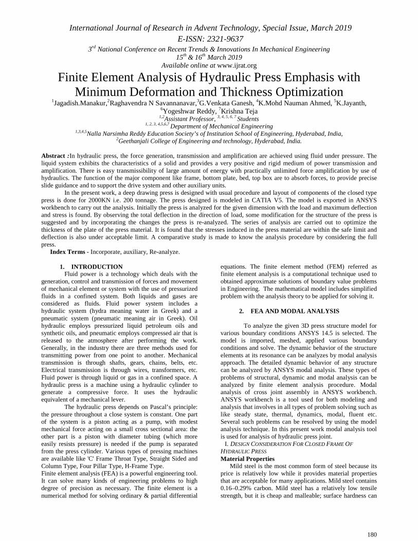
Fig 5.1: Imported model to ANSYS Workbench Fig 5.2: Discretization process
Fig 5.3: Apply boundary condition Fig 5.4: Equivalent stress distribution The .igs format in imported and carried the meshing(discretization) process has been done with the proper element size and structure(Fig 5.2). The various boundary condition like fixed support at the bottom, pressure at the donut (8.63Mpa), standard earth gravity for the press had been applied(fig:5.3). Default settings like iteration, time duration, and parametric calculation need be change before going to solver manager. Results like equivalent stress, principle stress, von misses stress are obtained, the max stress is application on donut area i.e. 30.668 MPa and minimum stress distribution is 6.9×10-
4MPa.
MODAL ANALYSIS OF HYDRAULIC PRESS STRUCTURE The dynamic behavior of the structure elements at its resonance can be analyzes by modal analysis approach. The detailed dynamic behavior of any structure can be analyzed by ANSYS modal analysis. These types of problems of structural, dynamic and modal analysis can be analyzed by finite element analysis procedure. Modal analysis of cross joint assembly in ANSYS workbench. ANSYS workbench is a tool used for both modeling and analysis that involves in all types of problem solving such as like steady state, thermal, dynamics, modal, fluent etc.
International Journal of Research in Advent Technology, Special Issue, March 2019 E-ISSN: 2321-9637
3rd National Conference on Recent Trends & Innovations In Mechanical Engineering 15th & 16th March 2019
Available online at www.ijrat.org
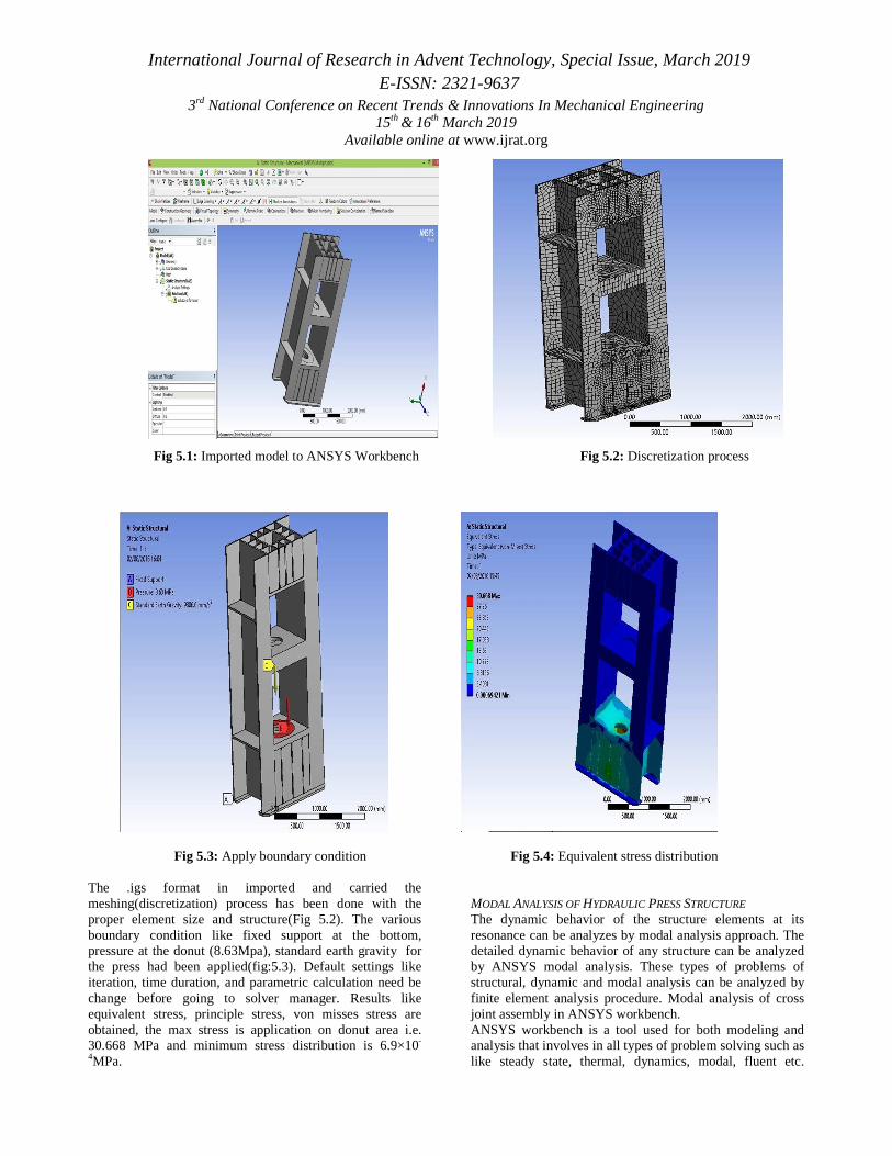
Several such problems can be resolved by using the model analysis technique. In this present work modal analysis tool
is used for analysis of hydraulic press joint. The steps are as follows for model analysis.
Fig 5.5: Importing Geometry Fig5.6:Mesh Generation Fig5.7: Apply Boundary Conditions
5. RESULT AND DISCUSSIONS
Several iterations were carried during the analysis, by varying the thickness of the base plate and applying the boundary conditions at different areas. The results obtained are compared with each other in this section and the structure with best results is highlighted. Following discussion gives the various results obtained from several iterations. ANALYSIS OF STRUCTURE HAVING
STIFFENERS OF LENGTH 500MM Initially the structures having stiffeners of 500mm length at the bottom is analyzed. The iterations of analysis are carried out by varying the plate thickness to 40mm, 45mm and 50mm and also by varying the area of applying the boundary condition.
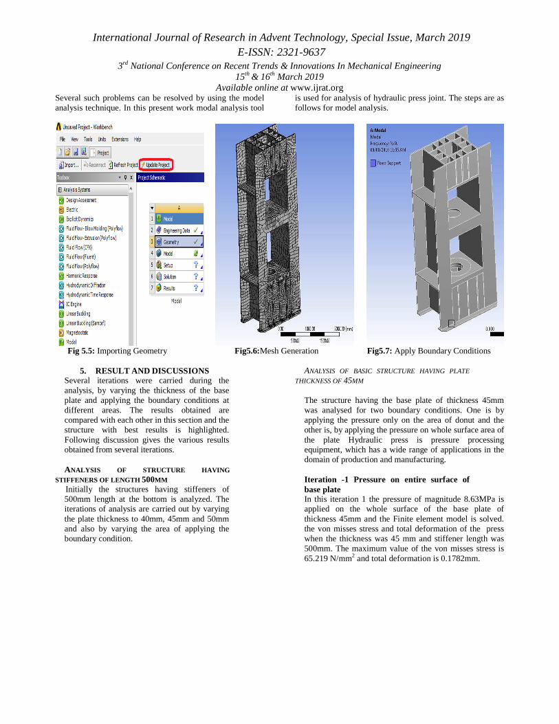
ANALYSIS OF BASIC STRUCTURE HAVING PLATE
THICKNESS OF 45MM The structure having the base plate of thickness 45mm was analysed for two boundary conditions. One is by applying the pressure only on the area of donut and the other is, by applying the pressure on whole surface area of the plate Hydraulic press is pressure processing equipment, which has a wide range of applications in the domain of production and manufacturing. Iteration -1 Pressure on entire surface of base plate In this iteration 1 the pressure of magnitude 8.63MPa is applied on the whole surface of the base plate of thickness 45mm and the Finite element model is solved. the von misses stress and total deformation of the press when the thickness was 45 mm and stiffener length was 500mm. The maximum value of the von misses stress is 65.219 N/mm2 and total deformation is 0.1782mm.

International Journal of Research in Advent Technology, Special Issue, March 2019 E-ISSN: 2321-9637
3rd National Conference on Recent Trends & Innovations In Mechanical Engineering 15th & 16th March 2019
Available online at www.ijrat.org
Fig 6.1: Results for Von Misses Stress of the Structure of 45mm Thick Base Plate When
Pressure is applied on entire surface of base plate
Fig6.2:Results for Total Deformation of the Structure of 45mm Thick Base Plate When Pressure
is applied on entire surface of base plate
For iteration-1, the maximum value of stress induced is 65.219MPa and the maximum total deformation obtained is 0.1782mm .The area indicated with red color in figure has the maximum stress and deformation as well. In the iteration-1 the drawing pressure is applied on the total top area of the drawing surface where the material is spread. But in the actual practice, when the drawing process is carried out the material is pressed in the center and the side material tends to lifting, hence a pad has to be prepared to apply the load by
considering the diameter of the donut as 2×diameter of the drawing hole.
Iteration-2 Pressure on donut surface Foriteration-2, it can be observed that the maximum value of stress induced for the given structure is 37.021MPa and the maximum total deformation obtained is 0.11975mm when the pressure applied on the donut area.

International Journal of Research in Advent Technology, Special Issue, March 2019 E-ISSN: 2321-9637
3rd National Conference on Recent Trends & Innovations In Mechanical Engineering 15th & 16th March 2019
Available online at www.ijrat.org
Fig 6.3: Results for Von Misses Stress of the Structure of 45mm Thick Base Plate When
Pressure is applied on the Donut Area
Fig6.4:Results for Total Deformation of the Structure of 45mm Thick Base Plate When Pressure
is applied on the Donut Area
Iteration-3 Pressure on donut surface and stiffness length up to full base length In this iteration the pressure of magnitude 8.63MPa is applied on the donut surface area and the Finite Element
model is solved. The following figure (6.5 &6.6) shows the results of the analysis
.
Fig 6.5:Von Misses Stress When the Length of Stiffener is increased up to Base Length for the
Structure of 45mm Thick Base Plate
Fig6.6:Total Deformation When the Length of Stiffener is increased up to Base Length for the
Structure of 45mm Thick Base Plate
International Journal of Research in Advent Technology, Special Issue, March 2019 E-ISSN: 2321-9637
3rd National Conference on Recent Trends & Innovations In Mechanical Engineering 15th & 16th March 2019
Available online at www.ijrat.org
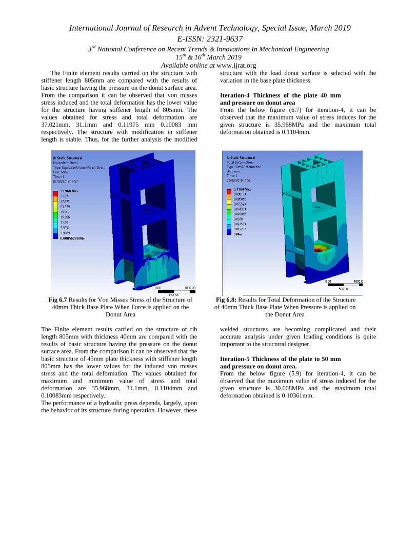
The Finite element results carried on the structure with stiffener length 805mm are compared with the results of basic structure having the pressure on the donut surface area. From the comparison it can be observed that von misses stress induced and the total deformation has the lower value for the structure having stiffener length of 805mm. The values obtained for stress and total deformation are 37.021mm, 31.1mm and 0.11975 mm 0.10083 mm respectively. The structure with modification in stiffener length is stable. Thus, for the further analysis the modified
structure with the load donut surface is selected with the variation in the base plate thickness.
Iteration-4 Thickness of the plate 40 mm and pressure on donut area From the below figure (6.7) for iteration-4, it can be observed that the maximum value of stress induces for the given structure is 35.968MPa and the maximum total deformation obtained is 0.1104mm.
Fig 6.7 Results for Von Misses Stress of the Structure of 40mm Thick Base Plate When Force is applied on the
Donut Area
Fig 6.8: Results for Total Deformation of the Structure of 40mm Thick Base Plate When Pressure is applied on
the Donut Area The Finite element results carried on the structure of rib length 805mm with thickness 40mm are compared with the results of basic structure having the pressure on the donut surface area. From the comparison it can be observed that the basic structure of 45mm plate thickness with stiffener length 805mm has the lower values for the induced von misses stress and the total deformation. The values obtained for maximum and minimum value of stress and total deformation are 35.968mm, 31.1mm, 0.1104mm and 0.10083mm respectively. The performance of a hydraulic press depends, largely, upon the behavior of its structure during operation. However, these
welded structures are becoming complicated and their accurate analysis under given loading conditions is quite important to the structural designer. Iteration-5 Thickness of the plate to 50 mm and pressure on donut area. From the below figure (5.9) for iteration-4, it can be observed that the maximum value of stress induced for the given structure is 30.668MPa and the maximum total deformation obtained is 0.10361mm.

International Journal of Research in Advent Technology, Special Issue, March 2019 E-ISSN: 2321-9637
3rd National Conference on Recent Trends & Innovations In Mechanical Engineering 15th & 16th March 2019
Available online at www.ijrat.org
Fig 6.8:Results for Von Misses Stress of the Structure of 50mm Thick Base Plate When Force is
applied on the Donut Area
Fig 6.9:Results for Total Deformation of the Structure of 50mm Thick Base Plate When
Pressure is applied on the Donut Area The Finite element results carried on the structure of rib length 805mm with thickness 50mm are compared with the results of basic structure having the pressure on the donut surface area. From the comparison it can be observed that the basic structure of 45mm plate thickness with stiffener length 805mm has the higher values for the induced von mises stress but, the total deformation is towards the lower side. The values obtained for maximum and minimum stress and total deformation are 30.668& 31.1 and 0.10361 & 0.10083 respectively. With the comparisons of all the iterations carried out it can be conclude that, the structure with full length of stiffener of 805mm having the plate thickness of 50mm processes the lower value for the induced von mises stress. The structure
with full length of stiffener of 805mm having the plate thickness of 45mm processes the lower value for the total deformation. Since, the value of von mises stresses and total deformations for both the structures which are in close agreement. Thus, anyone of the structure can be preferred depending upon the application. Press design methods have changed within a short span of time from empiricism to rational design methods; with the advent and widespread use of digital computers, it has now become feasible to develop analytical models and computer programs to apply numerical techniques with varying degrees of approximations to the design problems.
Iteration-6 Pressure on donut surface area on half section.
Fig 6.10:Results for Von Misses Stress of the Half Plate Structure of 50mm Thick Base Plate When
Pressure is applied on the Donut Area
Fig 6.11:Results for Total Deformation of the Half Plate Structure of 50mm Thick Base Plate When
Pressure is applied on the Donut Area
International Journal of Research in Advent Technology, Special Issue, March 2019 E-ISSN: 2321-9637
3rd National Conference on Recent Trends & Innovations In Mechanical Engineering 15th & 16th March 2019
Available online at www.ijrat.org
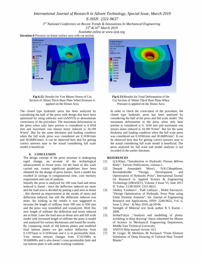
Iteration-6 Pressure on donut surface area with cut section
Fig 6.12: Results for Von Misses Stress of Cut Section of 50mm Thick Base Plate When Pressure is
applied on the Donut Area
Fig 6.13:Results for Total Deformation of the Cut Section of 50mm Thick Base Plate When
Pressure is applied on the Donut Area
The closed type hydraulic press has been analyzed by considering the half of the press with design that have been optimized by using software tool (ANSYS) to demonstrate correctness of the procedure. The maximum deformation in the press when only base portion is considered is 0.1034 mm and maximum von misses stress induced is 34.109 N/mm2. But for the same thickness and loading condition when the full scale press was considered are 0.10361mm and 30.668N/mm2. It can be observed here that for getting correct answers near to the actual considering full scale model is beneficial.
6. CONCLUSION
The design concept of the press structure is undergoing rapid change, on account of the technological advancements in recent years. On the basis of this work carried out, certain significant guidelines have been obtained for the design of press frames. Such a model has resulted in savings in computational time, core memory requirement and cost of analysis. Initially the press is analyzed for 200 tone load and stress induced is found , since the deflection induced are more and the load area is decided by putting a pad area as donut , this showed an improvement in the results of stress and deflection induced, but still the deflection induced was more. By looking at the results it was suggested to increase the length of stiffener from 500 mm to 850 mm and the press was remodeled and reanalyzed. With this new length of stiffener the deflection and stress induced are in limit. Later the load area as donut area and full scale model with increased length of stiffener the press is model and analyzed for various thicknesses and found the results. By comparing result of old bottom platen and modified final bottom platen we get reduce deflection from 0.11975mm to 0.10361mm and it is in permissible limit. Von- misses stresses changes from 37.021MPa to 30.668MPa and it also doesn’t cross permissible limit and our bottom plate is safe under working condition.
In order to check the correctness of the procedure, the closed type hydraulic press has been analyzed by considering the half of the press and full scale model. The maximum deformation in the press when only base portion is considered is 0, 1034 mm and maximum von misses stress induced is 34.109 N/mm2. But for the same thickness and loading condition when the full scale press was considered are 0.10361mm and 30.668N/mm2. It can be observed here that for getting correct answers near to the actual considering full scale model is beneficial. The press analyzed for full scale and model analyses is not recorded in the earlier literature.
REFERENCES
[1] Q.S.Khan, “Introduction to Hydraulic Presses &Press Body”, Tanveer Publications, volume-1.
[2] Deepak Annasaheb More1, N.K.Chhapkhane, RavindraKolhe “Design, Development and Optimization of Hydraulic Press”, International Journal for Research in Applied Science & Engineering Technology (IJRASET), Volume 3 Issue VI, June 2015 IC Value: 13.98 ISSN: 2321-9653.
[3] Akshay Vaishnav1 , Path Lathiya2 , Mohit Sarvaiya3, “Design Optimization of Hydraulic Press Plate using Finite Element Analysis”, Int. Journal of Engineering Research and Applications, ISSN: 2248-9622, Vol. 6, Issue 5, (Part - 4) May 2016, pp.58-66.
[4] Strength of Meterial text book author R S Kurmi – 2008.
[5] SerhatYalçin ,“Analysis and modelling of plastic wrinkling in deep drawing” thesis submitted for Master of Science in Mechanical Engineering Department, Middle East Technical University.
[6] ANSYS Help manual version 14.5 [7] M. Geiger, M. Merklein, M. Kerausch “Finite Element
Simulation of Deep Drawing of Tailored Heat Treated Blanks”.

International Journal of Research in Advent Technology, Special Issue, March 2019 E-ISSN: 2321-9637
3rd National Conference on Recent Trends & Innovations In Mechanical Engineering 15th & 16th March 2019
Available online at www.ijrat.org
191
[8] Ajay Kumar Choubey, GeetaAgnihotri, C. Sasikumar “Numerical Validation of Experimental Result in Deep-Drawing”, 4th International Conference on Materials Processing and Characterization.
[9] SusilaCandra, I Made LondenBatana, WajanBerataa, AgusSigitPramono “Analytical study and FEM simulation of the maximum varying blank holderforce to prevent cracking on cylindrical cup deep drawing”. 12th Global Conference on Sustainable Manufacturing.
[10] Wenzheng Dong, Qiquan Lin, Yantao Li, Zhigang Wang “Analytical and FEM investigations on boss forming process by compression-drawing method”. 11th International Conference on Technology of Plasticity, ICTP 2014, 19-24 October 2014,Nagoya Congress Center, Nagoya, Japan.
[11] Kaftanoglu B., “Plastic Analysis of Flange Wrinkling in Axisymmetrical Deep Drawing”. Proceedings of the
21st International Machine Tool Design and Research Conference, 1980, pp.21–28.
[12] Ramaekers J.A.H, de Winter A., Kessels M.W.H., “Deep drawability of a Round Cylindrical Cup”, IDDRG’94, 1994, pp.403–412.
[13] Cao J., Boyce M.C., “A Predictive Tool for Delaying Wrinkling and Tearing Failures in Sheet Metal Forming”, Transactions of the ASME, Vol.119, October 1997, pp.354–365.
[14] Cao J. “Prediction of Plastic Wrinkling Using the Energy Method”, Journal of Applied Mechanics, Vol.66, September 1999,
[15] Zeng X.M., Mahdavian S.M., “Critical Conditions of Wrinkling in Deep Drawing at Elevated Temperature”, Journal of Materials Processing Technology, Vol.84,1998, pp.38–46.