Finite Element Analysis of Cold{Formed Steel Structural ... · PDF filecold–formed steel...
14
Mechanics and Mechanical Engineering Vol. 17, No. 2 (2013) 127–139 c ⃝ Lodz University of Technology Finite Element Analysis of Cold–Formed Steel Structural Members with Performations Subjected to Compression Loading Martin MacDonald Muditha P. Kulatunga School of Engineering & Built Environment Glasgow Caledonian University Glasgow, UK Received (11 March 2013) Revised (17 April 2013) Accepted (19 May 2013) Numerical investigation on the behaviour of cold–formed thin–walled steel structural members with perforations is presented in this paper. Many structural cold–formed steel members are provided with cut–outs to accommodate electrical, plumbing, and heating services and so on. Due to the position of cut–outs, the elastic stiffness and ultimate strength of a structural member could be varied. The primary interest of this paper is to study the possible buckling occurrence on cold formed steel structural sections used as columns with perforations. Initially, a reliable finite element model was generated using the ANSYS software package to be able to predict the ultimate strength of cold–formed structural sections and to obtain a better understanding of the buckling failure behaviour highlighted, and conclusions will be drawn on this basis. Keywords : Cold formed structures, buckling failure, Finite Elements Analysis. 1. Introduction In steel construction cold–formed structural members are becoming more popular and have a growing importance. Cold-formed steel exhibits a versatile nature which allows for the forming of almost any section geometry [1]. Cold–formed steel sections are usually thinner than hot–rolled sections and can be subject to different modes of failure and deformation and therefore extensive testing is required to provide a guideline for the design of cold–formed thin–walled structural members [2]. The main mechanical properties (yield point, tensile strength and ductility) of cold–formed steel sections, particularly at the corners, are considerably different from those of the flat steel sheet, plate, strip or bar before forming. This is because the cold–forming operation increases the yield point and tensile strength, and at the same time decreases the ductility. Design codes have been generated in different
Transcript of Finite Element Analysis of Cold{Formed Steel Structural ... · PDF filecold–formed steel...

Mechanics and Mechanical Engineering
Vol. 17, No. 2 (2013) 127–139c⃝ Lodz University of Technology
Finite Element Analysis of Cold–Formed Steel StructuralMembers with Performations Subjected
to Compression Loading
Martin MacDonaldMuditha P. Kulatunga
School of Engineering & Built EnvironmentGlasgow Caledonian University
Glasgow, UK
Received (11 March 2013)
Revised (17 April 2013)
Accepted (19 May 2013)
Numerical investigation on the behaviour of cold–formed thin–walled steel structuralmembers with perforations is presented in this paper. Many structural cold–formed steelmembers are provided with cut–outs to accommodate electrical, plumbing, and heatingservices and so on. Due to the position of cut–outs, the elastic stiffness and ultimatestrength of a structural member could be varied. The primary interest of this paper is tostudy the possible buckling occurrence on cold formed steel structural sections used ascolumns with perforations. Initially, a reliable finite element model was generated usingthe ANSYS software package to be able to predict the ultimate strength of cold–formedstructural sections and to obtain a better understanding of the buckling failure behaviourhighlighted, and conclusions will be drawn on this basis.
Keywords: Cold formed structures, buckling failure, Finite Elements Analysis.
1. Introduction
In steel construction cold–formed structural members are becoming more popularand have a growing importance. Cold-formed steel exhibits a versatile nature whichallows for the forming of almost any section geometry [1]. Cold–formed steel sectionsare usually thinner than hot–rolled sections and can be subject to different modesof failure and deformation and therefore extensive testing is required to provide aguideline for the design of cold–formed thin–walled structural members [2].
The main mechanical properties (yield point, tensile strength and ductility) ofcold–formed steel sections, particularly at the corners, are considerably differentfrom those of the flat steel sheet, plate, strip or bar before forming. This is becausethe cold–forming operation increases the yield point and tensile strength, and atthe same time decreases the ductility. Design codes have been generated in different

128 MacDonald, M, Kulatunga, M.P.
countries [3], [4], [5], and [6] amongst many others for cold-formed steel structuressubjected to various loading scenarios which can cause buckling, bending and webcrippling or a combination. Many structural cold–formed steel members are pro-vided with perforations of different shapesto accommodate electrical, plumbing, andheating services and so on as illustrated in Figure 1. The position of suchperfora-tions can affectthe elastic stiffness and ultimate strength of a structural member[7].
1.1. Effects of perforations
In practice, perforations are either pre–punched or punched on–site on the cold–formed sections, to pass through conduits, utility ducts, etc [8]. The presence ofperforations in a structural member has often created a number of problems anddrawbacks and complicates the design process. In general the effect of perforationsmade specifically for fasteners such as bolts, screws, etc. on the overall strength ofa structure may be neglected as holes are filled with material. However, any otheropenings/perforations generated and not filled with replacement material creates areduced cross sectional area and cross sectional properties and this should be takeninto account in any analysis. The effect of perforations on the structure is examinedby testing and analysis. Leading design rules for cold–formed steel members withperforations are largely based on empirical formulae which have been developedby numerous researchers in the past, and are limited to certain perforation sizes,shapes, orientations, and positions. These limitations have created a number ofproblems and can decrease the reliability of cold–formed steel sections in the build-ing construction industry [9]. The results of the investigations of cold–formed steelstructural members with perforations, previously conducted by various researchers,have found that a concentrated load that may potentially cause deformation of thestructure is applied over perforations. However, it has been identified that due tothe shape of the perforations and the thickness of the sections and for other practicalreasons, reinforcement of these perforations in thin–walled members is not possible.
2. Buckling behaviour of cold–formed structural members
Unlike heavy hot–rolled steel sections, cold–formed thin–walled sections tend tobuckle locally at stress levels lower than the yield strength of the material whenthey are subjected to various loading conditions. However, these members do notfail at these stress levels and continue to carry further loads. This phenomenon iscalled post-buckling behaviour. In thin-walled cold–formed steel structures, elasticbucking and load deformation response are closely related. The influence of per-forations may promote unique buckling modes and can encourage collapse mecha-nisms at the ultimate state [10]. During the last few decades, the research workon thin–walled cold–formed steel members with perforation has showed failures oc-curred due to high stress concentrations around perforations, especially in the sharpcorner areas, irrespective oftheir shapes and configurations [11]. There are differ-ent buckling modes as illustrated in Figure 2: Local [12], Distortional [12], Euler,Torsional–Flexural and Lateral–Torsional [13].

Finite Element Analysis of Cold–Formed Steel ... 129
Figure 1 Perforations for fasteners
(a) Locally buckled plain channel [ 15].
(b) Distortional buckling behaviour ofcompressed structural members [15].
(c) Nonlinear locally buckled and Flexural -torsional buckling mode [ 15].
Section A-AA
Figure 2 Different buckling modes

130 MacDonald, M, Kulatunga, M.P.
It is well known that cold–formed thin–walled members under compression loadexhibit local and global post buckling behaviour[14]. Overall column strength isgreatly dependenton the interaction effect of local and overall column buckling. Itis recognised that cold formed steel compression members may locally buckle beforethe applied load reaches the overall collapse load of the column. The influence oflocal buckling on column strength depends on the following factors: the slender-ness ratio of the column, the shape of the cross section, influence of cold work,the type of steel used and its mechanical properties, the type of governing overallcolumn buckling, effect of imperfection, effect of welding, interaction between planecomponents, effect of perforations, effect of residual stress etc. For short columns,local buckling occurs first leading to large deflections. Local buckling involves de-formation of the component plate elements of the section, with the plate junctionsremaining straight and occurs as plate buckling of individual slender elements in across-section as shown in Figure 2(a). In general, local buckling near the perforationcontrols the elastic buckling stress of the plates.
Distortional buckling is characterised by rotation of the flange at the flange/webjunction in members with edge stiffened elements and occurs only for open cross-sections where the compressed flanges buckle inward or outward along the lengthof a member as shown in Figure 2(b). This is the form of a ”semi–local” bucklingmode which can generally arise at somewhat longer wavelengths. The distortionalbuckling mode has been found to govern the strength of sections with intermediatelystiffened elements [16], [17]. The elastically determined post–buckling behaviour isgenerally stable, but in–plane deformations can encourage substantial membranestresses and rapidly produce yield and failure in the stiffeners [18], [19].
For long columns under compression load, Euler buckling is more likely to occurbefore any other instability failure and occurs by bending about the web[20]. Whenaslender member is subjected to an axial force, failure in the member takes placedue to torsion or bending rather than direct compression of the material. Further,if the compression member is not supported in the lateral direction the memberwill fail due to lateral buckling of the compression flange [21].This phenomenonoccurs when the flexural load increases to a critical limit. In wide–flange sections, ifthe compression flange buckles laterally, the cross section will also twist in torsion,resulting in a failure mode which represents lateral–torsional buckling. The lateraltorsional buckling strength of a section could be increased by using a bracing system.In general, bracing systems could be divided into two categories namely, lateralbracing and torsional bracing. Cold formed steel structures are made of thin steelsheets and have often mono symmetric or un–symmetric cross sections. Hencetheir lateral–torsional buckling behaviour is more complicated than that of doublysymmetric hot–rolled beams. Past research on lateral–torsional buckling of steelbeams has mainly concentrated on hot–rolled steel beams [22].
The buckling mode is influenced by cross–section geometry, end conditions, load-ing and material. Also, introducing perforations to structures has a significant effecton the critical buckling load and the buckling mode [23], [24].

Finite Element Analysis of Cold–Formed Steel ... 131
3. Numerical investigation
Finite Element Analysis (FEA) is an accurate and flexible technique to forecast theperformance of a structure, mechanism or process under different loading conditions.A general finite element procedure with a particular emphasis on analysing thin-walled members using ANSYS finite element software package is presented here.FEA is now commonly used early in a design process to try out new conceptsand optimise before any physical prototypes are made and tested.The three mainstages in an FEA are: generation of the model, solving the model, and saving andreviewing the results.
A commonly employed methodology to generate a finite element model in AN-SYS is the direct generation of the finite element model, creating a solid modelwithin ANSYS or importing a solid model created in a separate CAD system. Di-rect generation is employed when the model is fairly simple and provides muchmore control over the geometry and numbering of nodes and elements. However,for relatively large or complicated models this approach becomes less flexible. TheANSYS program has a large library of element types. These elements are mainlycategorised based on the features embedded into the element type. The commontypes of elements for structural analysis are categorised as link, plane, beam, solidand shell elements. In general, cold–formed thin–walled members such as chan-nel sections, encompass relatively thin webs, flanges and lips, and are subjected toloading through flanges. Further, these members can have large width–to–thicknessratios. Shell elements are often used to model thin–walled structures and pro-vide more accurate results with a reasonable solution time compared to volumeelements. SHELL181 is one of the shell elements in the ANSYS element libraryalong with many other shell elements such as SHELL43, SHELL93, etc [25] (Figure3(a)).SHELL181 has features which can represent thin–walled structures effectivelysuch as suitability for analysing thin to moderately–thick shell structures, suited forlinear, large rotation, and/or large strain nonlinear applications. Load can be ap-pliedusing a load bearing plate. SOLID45(Figure 3(b)) is one of the most suitableelement types among other elements such as SOLID46, SOLID65, and SOLID70etc. The element has plasticity, creep, swelling, stress stiffening, large deflection,and large strain capabilities.
Finite Element Analysis of a structure is mainly carried out to investigate thestructural behaviour of the structure due to various loading conditions. Hence, ac-curate modelling of the loading is vital. There are several ways of applying thenecessary loading to a structure: as displacements, structural forces or pressuresonto either geometric entities or a set of nodes in the finite element model if theinvestigation is a pure structural analysis. Boundary conditions are defined basedon supports, connections and contacts. In practice, boundary conditions can changeduring loading and could affect the final solution. However, these effects are dif-ficult to determine and are often neglected. Boundary conditions are applied byrestraining the displacements and/or rotations of a set of selected nodes and arevaried according to the structure. Many structures show one or more symmetrieswith regards to their geometries and loading. The model size is optimised by apply-ing appropriate boundary conditions along the planes of symmetry by identifyingsymmetric features [25].
132 MacDonald, M, Kulatunga, M.P.
Triangular option(Not recommended)
a) SHELL181 geometry
Prism option
b) SOLID45 geometrySurface coordinate system
Tetrahedral option(Not recommended)
Symmetry plane
Modeled potion
Free mesh Mapped mesh
c) Two dimensional plate model with symmstry d) Examples of transition free and mapped mesh
Figure 3 Element types (a, b),symmetry boundary condition (c), and mesh type (d) [25]
Meshing is an integral part of the computer aided engineering simulation process.The accuracy, convergence and speed of the solution depend on the density ofthe mesh. Furthermore, the time it takes to create and mesh a model is often asignificant portion of the time it takes to get results from a CAE solution. Therefore,better and more automated meshing tools give better results. Three basic steps areinvolved in the meshing process:element attributes, mesh controls, and meshing themodel.
During the solution process ANSYS program performs a series of statistical op-erations using a system of simultaneous equations generated from the finite elementmodel and corresponding nodal results are stored. ANSYS provides several typesof equation solvers depending on the analysis type. The type of analysis could bestatic, buckling, transient or modal and must be specified at the beginning of thesolution process. The type of analysis depends on the behaviour of the systembeing examined and the results expected. Structural behaviour could be analysedon the basis of its linear or nonlinear response to external forces. Linear analysisprovides a fast solution and usually with less amount of modelling time. However,small displacements and rotations within the linear range of material behaviour willgive accurate results. In real circumstances structures exhibit nonlinear behaviourwithin their actual loading ranges, mainly due to geometric nonlinearities, mate-rial nonlinearities and changing status. ANSYS uses the Newton-Raphson methodto solve nonlinear problems. This iterative procedure continues until the problemconverges.

Finite Element Analysis of Cold–Formed Steel ... 133
4. Analysis of buckling behaviour of stub columns
In this design exercise, buckling behaviour of a thin walled cold formed ”C ” sectionwas analysedunder compression loading as detailed in Figure 4. Further, the perfo-rationposition and number of perforations presented in the structure were studied.In the construction industry perforationsare often used for various design purposesand they may be varied with respect to size,shape and position. Perforations arecreated using a method such as drilling and stamping etc.Areas around perforationsare more vulnerable to high stresses leading to possible failure around these regions.Hence, a careful study is required to define the perforation size, position etc. on astructure to keep stresses and strains within acceptable levels.Research is structuredintotwo stages:first stage – Finite Element Analysis (FEA) been employed; secondstage – FEA results were compared with test results.
B=30 mm
H=60 mm
h=8 mm
t=0.75 mm
r=2 mm
Figure 4 a) p2-wnf perforated on the web near the flanges at 1/4 and 3/4 of the width of theweb, b) p2–fnoe perforated on the flanges near the outer edges at 2/3 of the width of the flanges
Displacement
Section
Fixed end
p2-wfn p2-fnoe
Figure 5 Schematic view of ”C” sections with end support/load bearing plate
134 MacDonald, M, Kulatunga, M.P.
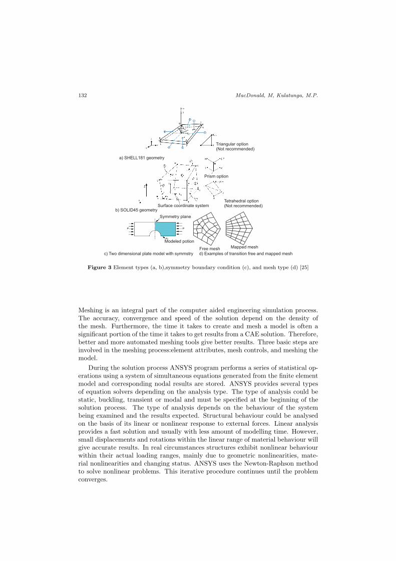
Fig. 5 shows schematic views highlighting perforations and position, withone endof the structure fixed and load is applied from the other end with the aid of a loadbearing plate. This position represents the pinned–pinnedcondition and gives theoption to apply load uniformly along the edge of loading face.
Two different types of sections have been used for the FEA analysis and thecross–section is constant. A circular shape perforation is used throughout the anal-ysis as it is more commonly in steel structures, and the load is applied using a loadbearing plate at the same speed rate.
a) Define cross-section b) Define area c) Generate mesh
Shear centre
Centroid of C chanel
e) Axis of symmetry
d) Load bearing plate
Figure 6 Generate section (a, b & c)/symmetry boundary condition (d & e)
4.1. Developing FE models for buckling behaviour
The cross section was modelled using key points, lines and arcs. Further, cross–section shape was dragged along a line to generate the section. Perforations werecreated by subtracting required areas from the section using subtract area commandand special attention was paid when selecting the relevant area. The sections,

Finite Element Analysis of Cold–Formed Steel ... 135
loading and support reactions were symmetrical about the vertical plane thereforeonly one–half of the section was modelled. Load was applied through a load bearingplate and the plate was modelled as a solid beam.
The section was developed using ANSYS element type SHELL181 as it is well–suited for linear, large rotation, and/or large strain nonlinear applications. Further,it is capable of handling change in thickness accounted for in nonlinear analyses. Forthe bearing plate ANSYS element type BEAM45 was used. The mapped meshingtechnique was used to generate a variable density mesh. Fine mesh was employedaround perforations and coarse mesh further away from the perforations. Figure6(c) shows the element mesh generated for p2–wnf model and illustrates differentregions of the element mesh.
Pinned–pinned boundary condition was applied for all loading cases. One endwas restricted for three degree of freedoms to represent the fixed end. Nodes inother end were coupled together to represent the fixed condition of the flange tothe load bearing plate. Load was applied as nodal displacements under the loadbearing plate. The symmetric boundary conditions shown in Fig. 6(e) were appliedat mid section of the member, Y–direction displacement was fixed and the rotationsabout the X–axis and Z–axis were also fixed. Load bearing plate was modeled as asolid block member the same as attached to the section. As a result, nodes adjacentto bearing plate move with the load bearing plate as it was given displacement torepresent compression load. At this point X and Z displacements were restricted,with Y displacement allowed.
Load is applied through a load bearing plate which represents the actual loadingconditions applied in the experiments. Load bearing plate and the top flange of thesection were connected by a pair of contact surfaces where nodes on flange edgerepresent same loading conditions as in load bearing plate.
5. Comparison
Results of the analysis were obtained by using ANSYS general postprocessor /POST1and time history postprocessor /POST26. These processors are built in the ANSYSsoftware and used for different functions. General postprocessor/POST1 was usedto view the results of the analysis and to obtain the various nodal stress and strainvalues and the deformed shape. History postprocessor/POST26 was used to provideresults over the time history and very useful in obtaining the load vs. deformationgraphs under load bearing plate and other critical locations. Load was appliedin terms of displacement and calculated against the displacement. Fig. 7 showsthe failure load plot for 2 specimens tested with comparisons to FEA, tests (fromexperimental investigations carried out by Rhodes and Schnieder [26]), Eurocodeand BS5950. Fig. 8 shows the load vs. displacement curves and Von Misesstressdistributionfor the 2 specimens obtained from FEA.
The comparisons of FEA, test results and design code predictions showed thatBS5950 andEurocodespecifications generally provide conservative strength predic-tions for ultimate buckling strength. Further, the study showed that, based onFinite Element Analysis and experimental evidence, slender cross–sections are sub-stantially affected by local buckling and high stress areas were seen around perfo-rations.

136 MacDonald, M, Kulatunga, M.P.
Table 1 Comparison of buckling failure load
Label ø hole NetCSA
CharacteristicalPositionof Perforation
Failure Load, kN
ANSYS Test BS5950
Eurocode3
p2 -wnf
2 x 8mm
87% Web nearflangesat 1/4and 3/4 thewidth of theweb
9.20 8.88 8.60 9.6
p2 -fnoe
2 x 8mm
87% Flangersnearouteredges at2/3 thewidthof the flanges
8.70 9.35 8.60 7.3
Figure 7 Comparison of buckling failure load
6. Conclusion
Finite element models were developed to simulate buckling failure of cold–formedchannel section columns with circular cut–outs under compression. ANSYS finiteelement package was used for the analysis and nonlinear material behaviour wasstudied in order to represent the plastic failure in the post–yield region. Resultsshowed that the displacement of the structure under compression varied significantlywith the cut–out position. The tests carried out in the experimental investigations

Finite Element Analysis of Cold–Formed Steel ... 137
p2-wnf
p2-fnoe
Figure 8 FEA results (load and displacement) for section p2–wnf& p2-fnoe
were capable of validating the buckling behaviour of channel sections as exhibitedin the FE models. The design codes predicted loads which weren’t very consistentwith the FEA and the test results and require further investigation.
There have been limited investigations into buckling behaviour of sections withcut–outs and it is understood that there are still no reliable equations or modelscapable of predicting the ultimate buckling strength. The next step of this researchwill be an extensive experimental program which is capable of confirming the FEAobservations obtained from this research, and results that can be used for furtherdeveloping finite element models and to inform analytical investigations and designcodes.

138 MacDonald, M, Kulatunga, M.P.
References
[1] Rhodes, J.: Design of Cold–Formed Steel Members, Elsevier Applied Science, Eng-land, ISBN 1 85166 595, 1, 1991.
[2] Yu, W. W.: Cold–Formed Steel Design, John Wiley & Sons, Canada, 3rd Edition,ISBN 0-471-34809-0, 2000.
[3] ENV 1993-1-3:2006, Eurocode: Design of Steel Structures; Part 1.3: General Rules- Supplementary Rules for Cold Formed Thin Gauge Members and Sheeting, 2009.
[4] British Standards Institution, British standards for structural use of steel workin buildings – Part 5: Code of practice for design of cold formed thin gauge sections,BS5950, 1998.
[5] American Iron and Steel Institute, Specification for the Design of Cold FormedSteel Structural Members, AISI–S100–07, 2007.
[6] AS/NZS4600, Cold–Formed Steel Structures, Standards Australia, Sydney, 2005.
[7] Don Allen, P. E.: Innovations in Cold–Formed Steel Framing, Insights, pp. 54–56,2007.
[8] Sivakumaran, K. M.: Web crippling Strength of Thin–Walled Steel Members withWeb Opening, Thin–Walled Structures, 8, pp.295–319, 1989.
[9] Cristopher, D.M.: Direct strength design of Cold-formed steel members with perfo-rations, The Johns Hopkins University, Department of Civil Engineering, Baltimore,2009.
[10] Cristopher, D. M. and Schafer, B. W.: Elastic buckling of thin plates with holesin compression or bending, Thin–Walled Structures, 47, pp.1597–1607, 2009.
[11] Zhenyu, Y. and Rasmussen, K. J. R.: Inelastic local buckling behaviour of per-forated plates and sections under compression, Thin–Walled Structures, 61, pp.49–70,2012.
[12] Teng, J. G. and Michael, R.: Buckling of thin metal shells, Spon Press, London,2004.
[13] Schafer, B. W., Pekoz, T.: Local and distortional Buckling of Cold–Formed SteelMembers with Edge Stiffened Flanges, [online] available at:
http://ceeserver.cee.cornell.edu/tp26/TWResearchGroup/tpadd/edgepap-corr.doc[accessed 10 January 2011].
[14] Kwon, Y. B. and Seo, G. H.: Prediction of the flexural strengths of welded H–sections with local buckling, Thin–Walled Structures, 54, pp.126–139, 2012.
[15] Young, B.: Local buckling and shift of effective centroid of slender sections, Availablethrough: University of Hong Kong [online] website
www.hkisc.org/proceedings/2006421/9 Ben-Young.pdf[accessed 10 January 2011].
[16] Teng, J.G. and Zhao, J. Y.: Distortional buckling of channel beam–columns,Thin–Walled Structures, 41, pp.595–617, 2003.
[17] Schafer, B. W. and Pekoz, T.: Local and distortional Buckling of Cold–FormedSteel Members with Edge Stiffened Flanges, [online] Available at :
http://ceeserver.cee.cornell.edu/tp26/twresearchgroup/tpadd/edgepap-corr.doc
[accessed 12 December 2011].
[18] Hancock, G. J.: Design for distortional buckling of flexural members, Thin–WalledStructures, 20:3–12, Elsevier, 1997.
[19] Yang, D. and Hancock, G. J.: Developments in design for distortional bucklingof thin walled members, ICTWS, University of Loughborough, 2004.

Finite Element Analysis of Cold–Formed Steel ... 139
[20] Dos Santos, E. S., Batista, E. M. and Camotim, D.: Experimental investiga-tion concerning lipped channel columns undergoing local–distortional–global bucklingmode interaction, Thin–Walled Structures, 54, pp. 19-34, 2012.
[21] Barbero, E. and Tomblin, J.: Euler Buckling of Thin-Walled Composite Columns,Thin–Walled Structures, 17, pp. 237-258, 1993.
[22] Kankanamge, N. D. and Mahendran, M.: Behaviour and design of cold–formedsteel beams subject to lateral–torsional buckling, Thin–Walled Structures, 51, ElsevierScience Ltd, pp. 25–38, 2012.
[23] Eurocode resources [online] available at:
http://www.eurocode-resources.com/buckling-a16.html [accessed 12 January 2011].
[24] AISI, Distortional buckling of cold–formed steel columns, Research Report rp. 00 –1, Revision, 2006.
[25] ANSYS, Inc, ANSYS Mechanical APDL Structural Analysis Guide: ANSYS Release13.0, USA, 2010.
[26] Rhodes, J. and Schneider, F.D.: Compressional Behaviour of Perforated Ele-ments, 12th International Specialty Conference on Cold–Formed Steel Structures, St.Louis, Missouri, USA, 1994.