Trigeminal System. uoanatomy/neuroanat/ Somatic sensory: A007 Sensory cranial: F003 Sensory cranial:
NASA/TM--2001-210892
Finite Element Analysis of Active and Sensory
Thermopiezoelectric Composite Materials
Ho-Jun Lee
Glenn Research Center, Cleveland, Ohio
National Aeronautics and
Space Administration
Glenn Research Center
May 2001
https://ntrs.nasa.gov/search.jsp?R=20010069273 2018-06-28T23:42:39+00:00Z

NASA Center for Aerospace Information7121 Standard Drive
Hanover, MD 21076
Available from
National Technical Information Service
5285 Port Royal Road
Springfield, VA 22100
Available electronically at http: //gltrs.grc.nasa.gov/GLTRS

CONTENTS
LIST OF ILLUSTRATIONS ..................................................... v
LIST OF TABLES ........................................................... vii
CHAPTER
1.1
1.2
1.3
1. INTRODUCTION ................................................. 1
Overview of Smart Structures .......................................... 1
Piezoelectric Materials ................................................ 1
Objectives of This Research ........................................... 2
CHAPTER
2.1
2.2
2. ANALYTICAL MODELING OF PIEZOELECTRIC MATERIALS ......... 3
Introduction ........................................................ 3
Induced Strain Models ................................................ 3
2.2.1 Actuator Models ............................................. 4
2.2.2 Actuator and Sensor Models ................................... 6
2.3 Coupled Electromechanical Models ..................................... 7
2.3.1 Analytical Models ........................................... 72.3.2 Finite Element Models ........................................ 7
2.4 Coupled Thermoelectromechanical Models ............................... 9
2.4.1 Analytical Models ........................................... 92.4.2 Finite Element Models ....................................... 10
2.5 Limitations of Existing Analytical Models ............................... 11
CHAPTER 3.
3.1
3.2
3.3
THEORETICAL DEVELOPMENT ................................. 13
Current Formulation Assumptions ...................................... 13
Governing Material Equations ......................................... 133.2.1 Strain and Electric Field in Cartesian Coordinates ................. 14
3.2.2 Strain and Electric Field in Curvilinear Coordinates ................ 14
Thermopiezoelectric Constitutive Equations .............................. 17
3.3.1 Piezoelectric Beam .......................................... 18
3.3.2 Piezoelectric Plate and Shell .................................. 18
CHAPTER 4. LAMINATE MECHANICS ........................................ 21
4.1 Layerwise Laminate Theory ........................................... 21
4.1.1 Beam Laminate Theory ...................................... 21
4.1.2 Plate Laminate Theory ....................................... 22
4.1.3 Shell Laminate Theory ....................................... 23
4.2 Generalized Laminate Matrices ........................................ 24
4.2.1 Beam Laminate Matrices ..................................... 24
4.2.2 Plate Laminate Matrices ...................................... 27
4.2.3 Shell Laminate Matrices ..................................... 29
NASA/TM--2001-210892 iii
CHAPTER5. FINITE ELEMENTFORMULATION ............................... 335.1 BeamElement ..................................................... 345.2 PlateElement ...................................................... 365.3 ShellElement...................................................... 38
CHAPTER6. CASESTUDIESAND DISCUSSIONOF RESULTS .................... 476.1 Comparisonswith RoomTemperatureExperimentalResults................. 47
6.1.1 PiezoelectricBimorphBeam ................................. 476.1.2 CompositePlatewith PiezoelectricPatches ...................... 47
6.2 Comparisonswith AnalyticalResultsfor TemperatureEffects ................ 546.2.1 PiezoelectricBimorphBeam .................................. 546.2.2 CompositePlatewith PiezoelectricPatches ...................... 54
6.3 Comparisonswith aCommercialFiniteElementAnalysisProgram............ 606.3.1 SensoryMode ............................................. 606.3.2 ActiveMode ............................................... 60
6.4 Additional NumericalStudies ......................................... 666.4.16.4.26.4.36.4.46.4.5
PyroelectricEffects ......................................... 66TemperatureDependentMaterialProperties...................... 70SelectiveShapeControlof BendingandTwisting ................. 78ThermalStresses........................................... 83Influenceof CurvatureonActive andSensoryResponse............ 89
CHAPTER7. CONCLUSIONSAND SUGGESTIONSFORFUTUREWORK .......... 1017.1 SuggestedPlanof FutureExperimentalStudies .......................... 101
REFERENCES ............................................................. 111
NASA/TM--2001-210892 iv
ILLUSTRATIONS
°
2.
3.
4.
,
6.
7.
8.
,
10.
11.
12.
13.
14.
15.
16.
17.
18.
19.
20.
21.
22.
23.
24.
25.
26.
27.
28.
29.
30.
31.
32.
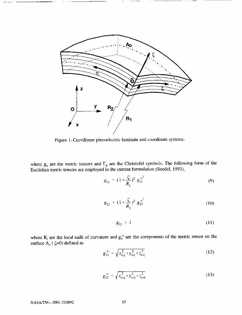
Curvilinear piezoelectric laminate and coordinate system ........................ 15
Piezoelectric bimorph beam (Lee and Moon, 1989) ............................ 48
Comparisons of deflections of a PVDF bimorph beam .......................... 49
Cantilevered composite plate with discrete piezoelectric patches
(Crawley and Lazarus, 1991) .............................................. 50
Comparisons of deflections of a [0/_+45]+ graphite/epoxy plate .................... 52
Comparisons of deflections of a [30/02] s graphite/epoxy plate .................... 53
Piezoelectric bimorph beam (Sunar and Rao, 1997) ............................ 55
Comparisons of thermal effects on the deflections of a
PVDF bimorph beam .................................................... 56
Simply supported composite plate with discrete piezoelectric patches
(Ha et al., 1992) ........................................................ 57
Comparisons of applied active voltage effects on the centerline
deflection of a [0/_+45]+ graphite/epoxy plate .................................. 59
Clamped composite plate with a piezoelectric layer ............................ 61
Comparison of centerline deflections of a clamped [08/p] plate ................... 63
Comparison of sensory electric potentials of a clamped [0s/p] plate ................ 64
Comparison of applied active voltage effects on the centerline
deflection of a clamped [08/p] plate ......................................... 65
Pyroelectric effects on the centerline deflections of a clamped [08/p] plate .......... 68
Pyroelectric effects on the sensory electric potentials of a
clamped [08/p] plate ..................................................... 69
Temperature dependence of AS4-3501-6 properties ............................ 71
Temperature dependence of PZT-5A properties d3t and _33 ....................... 72
Temperature dependence of PZT-5A properties at l, and P3 ...................... 73
Influence of temperature dependence on deflections at the center of a
[0/_+45]+ carbon/epoxy plate for different applied thermal gradients ................ 75
Influence of temperature dependence on sensory voltages at the center of a [0/_+45]+
carbon/epoxy plate for different applied thermal gradients ....................... 76
Influence of temperature dependence on applied voltages to minimize
the center deflection of a [0/_+45]+ carbon/epoxy plate for different
applied thermal gradients ................................................. 77
Initial bending and twisting deformation of a [453/-453] plate ..................... 79
Selective shape control of the bending deformation of a [453/-453] plate ............ 80
Selective shape control of the twisting deformation of a [453/-453] plate ............ 81
Shape control of bending and twisting deformations of a [453/-453] plate ........... 82
Cantilevered [0s/p] beam ................................................. 84
Comparison of normal stresses at the middle of a [08/p] beam .................... 86
Comparison of normal stresses at the free end of a [08/p] beam ................... 87
Comparison of shear stresses at the free end of a [08/p] beam ..................... 88
Geometry of a [09/p] circular cylinder with an attached piezoelectric layer .......... 90
Different types of applied thermal loads ..................................... 91
NASA/TM--2001-210892 v
33.
34.
35.
36.
37.
38.
39.
40.
41.
42.
43.
44.
45.
46.
Influence of pyroelectric effects on the displacements of a [09/p] circular
cylinder under a uniform thermal load ....................................... 92
Influence of pyroelectric effects on the sensory electric potential of a
[09/p] circular cylinder under a uniform thermal load ........................... 93
Influence of pyroelectric effects on the displacements of a [09/p] circular
cylinder under a cosine thermal load ........................................ 94
Influence of pyroelectric effects on the sensory electric potential of a
[09/p] circular cylinder under a cosine thermal load ............................ 95
Influence of pyroelectric effects on the displacements of a [09/p] circular
cylinder under a double cosine thermal load .................................. 96
Influence of pyroelectric effects on the sensory electric potential of a
[09/p] circular cylinder under a double cosine thermal load ...................... 97
Displacements of a [0_/p] circular cylinder under a uniform thermal load ........... 98
Displacements of a [09/p] circular cylinder under a cosine thermal load ............. 99
Displacements of a [09/p] circular cylinder under a double
cosine thermal load .................................................... 100
Dynamic experimental setup ............................................. 103
High temperature test configuration of a cantilevered beam with
one piezoelectric patch .................................................. 104
High temperature test configuration of a cantilevered beam with
two piezoelectric patches ................................................ 106
Test configuration of a flat plate with attached piezoelectric patches .............. 108
Test configuration of a curved plate with attached
piezoelectric patches ................................................... 109
NASA/TM--2001-210892 vi

TABLES
°
,-)_°
3.
4.
5.
6.
7.
8.
9.
10.
Material properties of PVDF piezoelectric polymer
(Lee and Moon, 1989) ................................................... 49
Material properties of piezoceramic (G-1195) and
Graphite/Epoxy (AS4/3501) (Crawley and Lazarus, 1991 ) ...................... 51
Material properties of PVDF piezoelectric polymer
(Sunar and Rao, 1997) ................................................... 56
Material properties of piezoceramic (G- 1195) and
Graphite/Epoxy (AS4/3501) (Ha et al., 1992) ................................ 58
Material properties of piezoceramic and Carbon/Epoxy ......................... 62
Material properties of piezoceramic and Carbon/Epoxy ......................... 67
Material properties of piezoceramic (PZT-5A) and
carbon/epoxy (AS4/3501-6) composite ...................................... 74
Material properties of piezoelectric and Graphite/Epoxy ........................ 85
Series of tests for a cantilevered beam with one piezoelectric patch ............... 105
Series of tests for a cantilevered beam with two piezoelectric patches ............. 107
NASA/TM--2001-210892 vii


CHAPTER 1
INTRODUCTION
Smart composite structures offer the capability to combine the low density, superior
mechanical and thermal properties of composite materials along with the inherent capabilities of
smart materials to sense and adapt to their environments. Thus, the use of smart structures (also
referred to as intelligent or adaptive structures) offers the potential to significantly improve the
performance of aerospace structural components. However, before these materials can be
implemented into actual structures, the coupled mechanical, electrical, and thermal behavior of smart
materials must be fully characterized. This has led to extensive research since the 1980's to assess
both the sensory and active responses of smart materials.
1.1 Overview of Smart Structures
Smart structures are distinguished from conventional structures by the presence of integrated
actuator and sensor elements. In a typical smart structure application, the sensors are used to monitor
the mechanical response of the structure through changes in the displacements, strains, or
accelerations. Once an adverse or undesirable structural response is detected in the sensors, a
controller generates the required input to the actuators. The actuators respond to this input and
produce a corresponding change in the mechanical response of the structure to a more benign or
acceptable state. The capability of smart structures to sense and adapt to their environment leads to
a wide range of potential applications including: vibration suppression of aircraft structures; noise
contr31 of helicopter rotors; health monitoring of bridges; shape control of large space trusses;
aeroelastic control of aircraft lifting components; and seismic control of buildings. Crawley (1993)
and Loewy (1997) provide detailed overviews of the current state of smart structures research for
aerospace applications.
A variety of different materials can be utilized as either sensor or actuator elements in smart
structure applications. Depending on the specific material used, the sensor and actuator elements are
controlled through either electric, magnetic, thermal, or light energy. Some of the common actuator
and sensor materials include: piezoelectric materials, shape memory alloys, fiber optics,
electrostrictive materials, magnetostrictive materials, and electro-rheological fluids. Of the different
materials available for use in smart structures, only piezoelectric materials have the unique capability
to be used effectively as both actuator and sensor elements. Other advantages of piezoelectric
materials which help account for their widespread popularity include: simple integration into the
structure; a readily obtainable commercial supply of piezopolymers and piezoceramics; and
familiarity in using these materials gained from previous applications in transducers.
1.2 Piezoelectric Materials
Historically, piezoelectric materials have been utilized mainly as active structural elements
in transducers for application in strain gages, accelerometers, and sonar. Recently, the focus of
research has shifted away from the transducer applications toward the development of smart structure
applications which combine the active and sensory behavior of piezoelectric materials.
NASA/TM--2001-210892 1

Thebasiccharacteristicsof piezoelectricmaterialswhichallow for their useassensorsandactuatorsarethedirectpiezoelectriceffect,conversepiezoelectriceffect,andthepyroelectriceffect.In thedirectpiezoelectriceffect,theapplicationof a mechanicalloadon thepiezoelectricmaterialinducesanelectricalresponse.Throughmeasurementof thiselectricalresponse,themechanicalstateof deformationin thestructurecanbedeterminedandmonitored,leadingto thesensoryapplication.In contrast,the conversepiezoelectriceffect transformsanelectrical input in the piezoelectricmaterialintoacorrespondingmechanicalstrain.Thisleadstotheactiveapplicationsof piezoelectricmaterials,in whichthestateof deformationof thestructurecanbecontrolledor alteredby applyingtheappropriateelectricalinput.Thethirdcharacteristicbehavioris thepyroelectriceffect, in whichthepiezoelectricmaterialrespondsto changesin temperatureby producinganelectricalresponse,which will influenceboth thedirect andconversepiezoelectriceffectsin changingtemperatureenvironments.
1.3 Objectives of This Research
The renewed interest in the application of piezoelectric materials in smart structures has lead
to extensive efforts to fully characterize the sensory and active behavior of these materials. Due to
the complex coupled mechanical, electrical, and thermal behavior of piezoelectric materials, new
analytical formulations and mechanics are required to accurately analyze the response of smart
structures which contain piezoelectric elements. Thus, the purpose of this research is to develop
comprehensive mechanics for accurately predicting the sensory and active behavior of composite
laminates which contain piezoelectric elements. Special emphasis is placed on capturing the coupled
response at the material level through the thermopiezoelectric constitutive equations and to introduce
the displacements, electric potentials, and temperature as state variables in the analysis. This unified
representation of the coupled response leads to the inherent capability to model both the sensory and
active responses of piezoelectric composite laminates.
The mechanics incorporate a layerwise laminate theory for more accurate analysis of
displacements, strains, stresses, electric fields, and thermal fields, especially for thick laminates and
laminates which contain strong inhomogeneties through-the-thickness. Thermal effects which arise
from coefficient of thermal expansion mismatch, pyroelectric effects of the piezoelectric materials,
and temperature dependent material properties are explicitly accounted for in the formulation.
Corresponding finite element formulations are developed for piezoelectric beam, plate, and shell
elements to provide a more generalized capability for the static and dynamic analysis of piezoelectric
composite structures under arbitrary thermoelectromechanical loads and boundary conditions. The
accuracy of the current formulation is verified by comparison with published experimental data and
results from other analytical models. Additional numerical studies are also conducted to demonstrate
additional capabilities of the formulation to represent the sensory and active behaviors. A future plan
of experimental studies is also provided to characterize the high temperature dynamic response of
piezoelectric composite materials.
NASA/TM--2001-210892 2
CHAPTER2ANALYTICAL MODELING OFPIEZOELECTRICMATERIALS
2.1 Introduction
The initial use of piezoelectric materials dates back to 1880, when the Curie brothers first
discovered the direct piezoelectric effect. Until recently, the use of piezoelectric materials has been
limited to a variety of transducer applications. The widespread use of piezoelectric materials as
distributed actuators began only in the 1980's, when advances in design and manufacturing
technologies made these applications feasible. The experimental work of Bailey and Hubbard (1985)
is usually cited as the first application of piezoelectric materials as actuators for vibration control.
Using a piezoelectric polymer film as the active element on a cantilevered beam, they were able to
demonstrate active damping of the first vibrational mode. This new actuator application has led to
renewed interest in the development of piezoelectric materials for advanced aerospace structures.
As research into characterizing the active and sensory behavior of piezoelectric materials
progressed, a variety of different analytical models were developed. These models can be classified
into three broad categories as induced strain models, coupled electromechanical models, and coupled
thermoelectromechanical models. The induced strain models use approximate theories to incorporate
the piezoelectric effects and are generally limited to predicting only the active response of
piezoelectric materials since the electric potential is neglected as a state variable in the formulation.
The coupled electromechanical models provide a more consistent representation of both the sensory
and active responses of piezoelectric materials by incorporating both the displacements and electric
potential as state variables in the formulation. Typically, these models are implemented as finite
element codes to provide a more general analysis tool and a wide variety of different beam, plate,
shell, and solid elements have been developed. A natural extension of the coupled electromechanical
models is to also incorporate thermal effects. These coupled thermoelectromechanical models
include temperature as an additional state variable to account for thermal effects in addition to the
piezoelectric effects. A more limited number of finite element codes have been developed with this
capability.
2.2 Induced Strain Models
The induced strain models can be separated into two categories: (1) actuator models and (2)
actuator and sensor models. The actuator models are concerned only with analyzing the active
behavior of piezoelectric materials. They typically approximate the strain generated in the
piezoelectric material by an applied electric voltage using statically equivalent forces and moments.
The combined actuator and sensor models were developed to include predictions of the sensory
response of piezoelectric materials. Although these models introduce the piezoelectric constitutive
equations into their formulation, the electric potential is usually not included as a state variable, the
conservation of electric flux is not considered in the equations of motion, and the sensory voltages
are back calculated using the charge equation.
NASA/TM--2001-210892 3
2.2.1ActuatorModels
CrawleyanddeLuis (1987)developedaninducedstrainactuatormodelfor beams.Theyformulatedstaticanddynamicanalyticalmodelsbasedonthegoverningequationsfor beamswithattachedandembeddedpiezoelectricactuatorsto modelextensionandbending.Experimentswereperformedon both isotropic and compositecantileveredbeamswith attachedand embeddedpiezoelectricactuatorstovalidatetheirmodels.Thestudyfoundthatsegmentedactuatorsarealwaysmoreeffective thancontinuousactuatorssincethe outputof eachactuatorcanbe individuallycontrolled. Theyalsoshowedthatembeddedactuatorsin compositesdegradetheultimatetensilestrength,but havenoeffecton theelasticmodulus. BazandPoh (1988)investigatedmethodstooptimizethe locationof piezoelectricactuatorson beamsto minimize thevibration amplitudes.Numericalstudiesdemonstratedthepotentialtocontrol vibrationsin largeflexible structuresusingasmallnumberof bondedpiezoelectricactuators.Im andAtluri (1989)presentedamorecompletebeammodelwhich accountedfor transverseandaxial deformationsin addition to extensionandbending.Governingequationswereformulatedfor abeamwith bondedpiezoelectricactuatorsforapplicationsin dynamicmotioncontrolof largescaleflexible spacestructures.
TzouandGadre(1989)formulatedaninducedstrainpiezoelectricshelltheory. A dynamicmodelwasderivedfrom Love'sshelltheoryfor applicationto multi-layeredthin shellswith activedistributedactuators. A casestudywas validatedwith experimentalresults for the vibrationsuppressionof a cantileveredbeamwith a piezopolymeractuatorfilm. CrawleyandAnderson(1990)developedaBernoulli-Eulermodel to moreaccuratelymodelactuationinducedextensionandbendingin one-dimensionalbeamsthanthemodelof CrawleyanddeLuis (1987). Themodelneglectedsheareffectsandwasshownto bebestsuitedfor theanalysisof thinbeamsandactuators.Clarket al. (1991)alsoextendedthemodelof CrawleyanddeLuis (1987)to studytheresponseofmultiplepiezoelectricactuatorsonbeamexcitations.BasedonEulerbeamtheory,theirmodelwasvalidatedwithexperimentalresultsfor thevibrationresponseof asimplysupportedisotropicbeam.The modelwas found to bebestsuited for performing initial studiesto determinetheoptimallocationof actuatorsfor excitingspecificvibrationmodes.
CrawleyandLazarus(1991)developedinducedstrainactuationmodelsfor plates.Equationsofstrainactuationwerederivedforbothisotropicandanisotropicplates.Exactsolutionswerefoundfor simplegeometriesandboundaryconditions,while approximatesolutionswereusedto solvemorecomplexproblems.Themodelswereverifiedwith experimentalresults.Staticanalysisof acantileveredcompositeplate with attachedpiezoceramicactuatorswereconductedto showthepotentialfor shapecontrol of structures.Dimitriadis et al. (1991)extendedtheone-dimensionalinducedstrainbeammodelof CrawleyanddeLuis (1987)to two-dimensionalplateswith bondedpiezoelectricactuators. Dynamic analyseswere performed on simply supportedplates todemonstratetheuseof actuatorsto exciteselectivemodesandtheinfluenceof actuatorgeometryon the modalresponse.RobbinsandReddy(1991)developeda piezoelectriclayerwiselaminatetheorywhichwasimplementedintoabeamelement.Numericalcomparisonswereconductedusingfourdifferentdisplacementtheories(twoequivalentsinglelayertheoriesandtwolayerwiselaminatetheories)to demonstratetheincreasedaccuracyin displacementandstresspredictionsobtainedfromusingthelayerwisetheories.
Wangand Rogers(1991) formulatedan inducedstrainpiezoelectricplate theory. TheformulationwasbasedonclassicallaminatedplatetheoryandusedHeavisidefunctionstorepresentthe distributedpiezoelectricactuators. The model was verified with the analytical work ofDimitriadis et al. (1991)andadditionalcasestudieswereperformedto demonstratethecapabilityof actuatorstoinducebendingandextensionin laminatedplates.Clarketal. (1993)experimentally
NASA/TM--2001-210892 4

validated the induced strain plate model developed by Dimitriadis et al. (1991 ). Results from the free
vibration analysis demonstrated capabilities to excite selective vibration modes of a simply supported
plate using bonded actuators, as well as the significance of actuator location and excitation frequency
on the structural response. Pai et al. (1993) accounted for geometric nonlinearities (large rotations
and displacements) in piezoelectric composite plates. The developed partial differential equations
characterize the dynamic response of composite plates through elastic and geometric couplings
between the extension, bending, and twisting motions.
Mitchell and Reddy (1995b) formulated a power series solution for axisymmetric composite
cylinders with either attached or embedded piezoelectric laminae. The solution was verified with
finite element analysis. Numerical studies were performed to damp vibrations in truss-type
structures using both an embedded cylindrical truss actuator element and an attached actuator patch.
Linet al. (1996) presented an induced actuation plate finite element based on first order shear
deformation theory. Numerical studies were verified with analytical solutions and demonstrated
capabilities to control the deflection of composite plates using piezoelectric actuators. Park and
Chopra (1996) formulated one-dimensional models to predict the extension, bending, and torsion
behavior of beams under piezoelectric actuation. Comparisons with experimental data showed good
correlation only for applications in which actuators have low orientation angles (less than 45 ° ) with
respect to the beam neutral axis.
Sonti and Jones (1996) developed differential equations of motion for a composite cylindrical
shell with surface bonded piezoelectric elements. Approximate analytical solutions were obtained
for the equivalent forces exerted by the actuator and shell. Chandrashekhara and Varadarajan (1997)
implemented a finite element model for laminated composite beams with integrated piezoelectric
actuators derived from a higher order shear deformation theory. Numerical studies investigated the
effect of stacking sequence and boundary conditions on the actuator voltages and demonstrated the
capability to achieve adaptive shape control of beam structures. Charette et al. (1997) formulated
analytical models based on a variational approach to study plates with piezoelectric actuators. The
model was specialized for a simply supported plate and used to determine the effects of piezoelectric
actuator on the dynamic behavior of the plate. Results of the study were verified with experiments
and showed only slight changes in the mode shapes of the plate.
Chattopadhyay and Seeley (1997) implemented a third-order laminate theory into a finite
element formulation to investigate piezoelectric actuators. Numerical results were verified with
published experimental data. Additional comparisons were conducted to demonstrate the limitations
of classical laminate theory in analyzing through-the-thickness stress and strain variations. Librescu
et al. (1997) presented a model for composite beams with piezoelectric actuators that included
structural tailoring and boundary-moment control. Numerical results demonstrated the potential to
improve the dynamic responses of thin-walled cantilevered structures. Bhattacharya et al. (1998)
developed a finite element formulation based on first order shear deformation theory for beams and
plates. An eight noded isoparametric piezoelectric element was developed to perform free vibration
analysis of laminated composite beams and plates. Numerical studies assessed the impact of stacking
sequence, boundary conditions, and applied electric potentials on the free vibration response.
Oguamanam et al. (1998) formulated a piezoelectric composite beam finite element using
von Karman nonlinear strain-displacement relations. Numerical studies demonstrated the influence
of stress stiffening effects on the natural frequency of slender beams. Tong et al. (1998) developed
a two dimensional thin plate finite element to investigate shape control applications. Numerical
NASA/TM--2001-210892 5
studies were performed to determine the optimum applied voltage, actuator layout, and actuator
number for shape control of composite plates with distributed piezoelectric actuators. Chattopadhyay
et al. (1999) implemented a third-order laminate theory into a finite element formulation to
investigate the dynamic response of delaminated smart composite plates. Numerical studies were
conducted on piezoelectric composite plates with single and multiple delaminations to demonstrate
changes in the dynamic response. Hong and Chopra (1999) developed an induced strain plate finite
element for composite plates based on classical laminate theory. The model was verified with
experimental results and demonstrated the capability to achieve shape control using piezoelectric
actuators.
2.2.2 Actuator and Sensor Models
Lee and Moon (1989) studied the control and sensing of bending and torsional deformations
produced by an applied electric field using piezopolymer bimorphs. The experimental results
validated the analytical model and demonstrated the use of piezopolymers as actuators. Lee (1990)
developed a model that incorporated the piezoelectric constitutive relations. The model was based
on classical laminated plate theory and was able to predict both the active and sensory behavior of
piezoelectric materials. Lee et al. (1991) investigated the use of sensor actuator pairs for active
damping control. Experimental studies were conducted on the active damping control of the first
mode of a cantilevered plate using a sensor and actuator pair to validate the piezoelectric plate
theory.
Chandrashekhara and Agarwal (1993) developed a laminated piezoelectric plate element
based on a first-order shear deformation theory applicable to both thin and moderately thick
laminates. Numerical results were verified with previously published results for a cantilevered plate
with attached piezoceramic actuators subjected to a static electric field. Hwang and Park (1993)
developed a piezoelectric plate element based on classical laminate theory and Hamilton's principle.
The piezoelectric constitutive relations were used to formulate a four noded, two-dimensional
quadrilateral plate element for both sensory and active applications. Case studies were performed
to investigate the static response of a piezoelectric bimorph beam and the vibration control of a
cantilevered plate with attached piezoelectric sensors and actuators. Koconis et al. (1994a, 1994b)
developed separate analytical models to investigate the sensory and active behavior of piezoelectric
composite beams, plates, and shells. One model is used to predict the change in shape when a
specified electric voltage is applied to the actuator, while the second model is used to determine the
electric voltages necessary to achieve a desired shape. Both models were formulated using a two-
dimensional, linear, shallow shell theory which includes transverse shear effects and validated with
other numerical, analytical, and experimental results.
Sung et al. (1996) derived sensor and actuator equations for a cylindrical piezoelectric
composite shell. Based on classical laminate theory, these equations formed the basis of a sensor
and actuator design methodology to control flexural and torsional vibrations in cylindrical shells.
This methodology was used to design an experimental rig to demonstrate capabilities of the modal
sensor and actuator to monitor and control the different vibration modes. Lam et al. (1997)
developed a finite element model based on classical laminated plate theory for the active vibration
control of composite plates with distributed piezoelectric actuators and sensors. Numerical studies
were conducted on a cantilevered composite plate to demonstrate capabilities for static and dynamic
analysis. Plettner and Abramovich (1997) implemented a consistent methodology based on Kirchoff-
NASA/TM--2001-210892 6

Love thin shell theory to model the static and dynamic responseof anisotropic laminatedpiezoelectricshells.Theformulationreplacedtheinducedpiezoelectricstrainwith anequivalentmechanicalload. The model was verified with experimentaland finite elementresults for arectangularisotropicplate.
Penget al. (1998)implementedabeamfinite elementusingathirdorderlaminatetheoryforactivevibrationcontrol of piezoelectriccompositebeams.Numerical studieswereconductedtoassessshapecontrolapplicationsandto investigatetheeffectof sensorandactuatorlocationsontheresponseof thebeam.Liu etal. (1999)formulatedaplatefiniteelementbasedonclassicallaminatedplate theory for modeling the static and dynamic responseof compositeplates containingpiezoelectricactuatorsandsensors.Numericalstudieswereconductedto verify the modelwithresultsfrom previouslydevelopedmodelsand to studythe influenceof stackingsequenceandsensor/actuatorpositionon theresponseof compositeplates.
2.3 Coupled Electromechanical Models
Attempts to develop a more comprehensive representation of piezoelectric material behavior
led to the development of more consistent models that captured the coupled response between the
mechanical and electrical behavior. In these coupled models, the charge equation is incorporated into
the equations of motion and the electric potential is introduced as an additional degree of freedom
in the analysis. These models are generally also implemented as finite element programs to provide
a more flexible and general purpose analytical tool.
2.3.1 Analytical Models
Mitchell and Reddy (1995a) formulated a refined hybrid theory for laminated piezoelectric
composite plates. The displacement fields are modeled using third order shear deformation theory
while electric potentials are represented using a layerwise laminate theory. An analytical solution
was developed for simply supported boundary conditions and numerical results demonstrated the
limitations of the induced strain methods in modeling thick laminates. Heyliger and Saravanos
(1995) developed exact solutions to predict the vibration characteristics of simply supported
laminated piezoelectric plates. Numerical studies were conducted to determine the influence of
different laminations and aspect ratios on the natural frequencies and mode shapes. Batra and Liang
(1997) developed three-dimensional elasticity solutions for the simply supported rectangular
laminated plate with embedded piezoelectric layers. Numerical studies examined the steady state
vibration of both thin and thick plates containing one actuator layer and one sensor layer.
2.3.2 Finite Element Models
The groundwork for much of the current research into finite element formulations was
initiated by Allik and Hughes (1970) with the development of a three-dimensional tetrahedron
element. Derived at a time when piezoelectric materials were used mainly as crystals in transducer
applications, the finite element formulation incorporated the piezoelectric constitutive relations and
NASA/TM--2001-210892 7
demonstrated the potential advantages of utilizing the finite element method. Naillon et al. (1983)
formulated a finite element model to study the resonance phenomena of single piezoelectric
structures typically used in ultrasonic transducers. Numerical studies were performed on the
resonance characteristics of two-dimensional parallelepiped bars to assess potential applications in
the design of ultrasonic probes. Lerch (1990) formulated two and three dimensional finite elements
for performing vibrational analysis of piezoelectric sensors and actuators. The models were verified
with experimental data. The natural frequencies and mode shapes of various piezoelectric structures
were determined and used to optimize applications as transducers.
Tzou and Tseng (1990) developed a thin piezoelectric solid element. Derived from
Hamilton's principle and the piezoelectric constitutive relations, the element is specifically
formulated for thin plate and shell structures with distributed piezoelectric sensors and actuators.
Numerical studies were performed on the vibration response of a cantilevered plate with both an
active and sensory layer of polymeric piezoelectric material. Lammering (1991) developed a
piezoelectric shell element. Based on the Reissner-Mindlin shell theory and incorporating the
piezoelectric constitutive equations, a shell element was formulated for thin shell structures with
attached piezoelectric layers. Case studies were conducted on a cantilevered beam with an attached
piezoelectric polymer layer. Ha et al. (1992) formulated a three-dimensional brick element. Using
a variational principle and the piezoelectric constitutive relations, they developed an eight-noded
solid element. Results from static and dynamic case studies were verified with experimental results
for composite plates with attached piezoceramic actuator and sensor patches.
Heyliger et. al. (1994) implemented a layerwise laminate theory into a finite element
formulation for plates. Two separate layerwise models were developed which incorporated the
coupled equations of piezoelectricity to account for both the active and sensory behavior of
laminated plates with piezoelectric layers. Numerical results for a simply supported composite plate
with attached polymer piezoelectric layers were verified with exact solutions. Ray et al. (1994)
developed a two-dimensional quadrilateral element using a higher order laminated plate theory. An
eight-noded quadratic isoparametric quadrilateral element was formulated. Results from the static
analysis of a simply supported cross-ply laminated plate bonded with a piezoelectric polymer were
verified using previously reported exact solutions. Shieh (1994) developed a multiaxially active and
sensory laminated piezoelectric beam element. Based on adjusted elementary beam assumptions to
account for warping effects, the element can simultaneously model axial extension, biaxial bending,
and torsional twisting of the beam. Numerical studies were performed on a space antenna frame to
demonstrate capabilities for three-dimensional multiaxial vibration control.
Saravanos and Heyliger (1995) developed a layerwise finite element formulation for beams.
Two separate theories were used to perform static and free vibration analysis of composite beams.
Numerical results were verified with previously published analytical studies and demonstrated the
increased accuracy of stress-strain predictions with the layerwise theory. Shen (1995) developed
a finite element formulation for beams containing piezoelectric actuators and sensors. Based on
Timoshenko beam theory, the methodology captured the coupling between the longitudinal and
bending motions. The theory was validated with previously published analytical results for a
piezoelectric polymer bimorph beam and experimental results for a cantilevered beam with attached
piezoelectric sensors and actuators. Suleman and Venkayya (1995) formulated a plate element for
analyzing composite plates with layered piezoelectric actuators and sensors. Based on classical
laminate theory, a four-noded bilinear Mindlin plate element was developed. Previously published
NASA/TM--2001-210892 8
experimental and analytical results for a cantilevered piezoelectric bimorph beam and a cantilevered
composite plate with distributed piezoelectric actuators were used to validate the formulation.
Donthireddy and Chandrashekhara (1996) also formulated a layerwise theory for beams.
Results from the static response of a cantilevered composite beam with attached piezoelectric
actuators was validated with previous analytical results. Additional parametric studies were
conducted to study the influence of boundary conditions and ply orientation on the shape control of
beams. Heyliger et al. (1996) implemented a layerwise laminate theory into a finite elementformulation for shells. Results were verified with exact solutions for the static and free vibration
response of a simply supported plate. Additional studies were performed on the active and sensory
response of a cylindrical shell. Kim et al. (1996) developed a transition element to connect three-
dimensional solid elements to flat shell elements. The reported approach used solid elements to
provide detailed models of the piezoelectric material, while flat shell elements were used to provide
a more flexible model for the substrate structure, and transition elements were used to connect the
two regions. The model was verified experimentally for a cantilevered plate.
Samanta et al. (1996) extended the eight-noded quadrilateral element developed by Ray et
al.(1994) for dynamic analysis. Based on a higher order shear deformable displacement theory, the
model was developed for active vibration control of laminated plates with integrated piezoelectric
layers. Numerical results were performed on a simply supported cross-ply plate with attached
piezopolymer layers to demonstrate the potential to achieve significant reductions in vibration
amplitude. Kim et al. (1997) provided additional details of the theoretical development of the
transition element reported by Kim et al. (1996). Numerical studies were conducted to demonstrate
convergence characteristics and to show the increased computational efficiency of this approach.
Saravanos (1997) presented a shell element for curvilinear piezoelectric laminates which combined
a first order shear deformation theory for the displacements along with a layerwise theory for the
electric potential. The quadratic element was intended for static and dynamic analysis of thin to
moderately thick shell structures. Numerical studies quantified the effects of curvature on the active
and sensory response of piezoelectric shells.
2.4 Coupled Thermoelectromechanical Models
All of the previously described models neglect the implication of thermal effects on both the
active and sensory response of piezoelectric structures. Although Mindlin (1974) derived the two-
dimensional thermopiezoelectric equations for plates over twenty years ago, only limited research
has been performed into this area. The development of models for thermopiezoelectric materials can
be separated into two categories: (1) analytical models and (2) finite element models. The analytic
models extend existing piezoelectric laminate theories to account for thermal effects and obtain
solutions for specific problems. The finite element models provide a more general purpose tool to
efficiently analyze complex problems.
2.4.1 Analytical Models
Tauchert (1992) developed a thermopiezoelectric laminate plate theory. His theory extended
classical laminate theory to account for thin laminated plates with thermopiezoelectric layers.
Specific solutions were developed for both free and simply supported composite plates with attached
piezoelectric polymer layers. Numerical results demonstrated the capability to reduce thermal
deformations through application of active electric voltages. Tzou and Howard (1994) formulated
NASA/TM--2001-210892 9

athermopiezoelectricthinshelltheoryfor applicationsto activestructures.Thegenericshelltheorywasderivedusing Kirchoff-Love shell theoryandHamilton'sprinciple. Using a simplificationprocedurebasedon theLameparametersandradii of curvatures,specificsolutionswereobtainedfor a cylindrical piezoelectricring, a piezoelectricring, anda piezoelectricbeam.TangandXu(1995) developeddynamic solutions for a simply supportedanisotropic piezothermoelasticcompositeplate.Thecouplingbetweentheelasticfield andthe electricand thermalfields wereneglectedto simplify the analysis. Numerical resultsdemonstrateda significant reduction indeflectionof aplatebytheadditionof apiezoelectriclayerwith a harmonicelectricfield.
Tzouand Bao(1995)extendedthethermopiezoelectricthin shelltheorydevelopedbyTzouand Howard (1994) for applicationsto anisotropicshell laminateswith distributedsensorsandactuators. The governingequationswere simplified and applied to a thin piezothermoelasticlaminatedshellmadeof apiezoelectricpolymer. Applicationsdemonstratedthecouplingbetweentheelastic,electric,andthermalfields andtheimportanceof all threefieldson theoverallbehaviorof theshell.StamandCarmen(1996)presentedaxisymmetricthermoelectromechanicalsolutionsfor concentricpiezoelectriccylinders.Theanalyticalapproachwasusedto model thequasistaticresponseof a linear piezoelectricmotor. Resultsof the studydemonstratedthe capability toextrapolatethenonlineardependenceof thepiezoelectriccoefficientswith electricfields to lowertemperaturesusingthe constitutiveequations.Friswell et al. (1997)developeda linearmodel toinvestigateactivedampingof thermallyinducedvibrations.Numericalstudieswereconductedona simply supportedaluminumbeamwith a piezoelectricsensor/actuatorpair to demonstratetheinfluenceof pyroelectriceffectson vibrationcontrol.
2.4.2FiniteElementModels
RaoandSunar(1993)developedafiniteelementformulationwithapplicationsfor integratedsensingandcontrol of thermopiezoelectricmaterials. Numerical studieswere performedon apiezoelectricbimorphbeamandanisotropicbeamwith attachedpiezoelectricpolymerlayers.Theresultsdemonstratedthesignificanceof thermaleffectson theperformanceof distributedcontrolsystems.Jonnalagaddaet al. (1994)implementeda nine-nodedLagrangianplateelementusingafirst-order sheardeformationtheory. Numericalstudieswereperformedon a simply supportedcompositeplatewith anattachedpiezoelectricactivelayeranddemonstratedtheimportanceof ahigherorderlaminatetheoryto accuratepredictsheardeformationsin thick laminates.TzouandYe(1994)extendedthepreviouslydevelopedsolidelementof TzouandTseng(1990) to accountforthermal effects. The resulting three-dimensionalthin hexahedronelement representedthedisplacements,electric potential,and temperatureas statevariables. Numerical studieswereperformedonacantileveredisotropicbeamwith attachedpiezoelectriclayersto demonstratetheinfluenceof thermaleffectsonsensingandcontrol.
Chandrashekharaand Tenneti (1995)developeda nine-nodedfinite elementfor activethermal control of compositeplates with piezoelectricactuatorsand sensors.The approachincorporatedan inducedstrainapproachto approximatethe piezoelectricand thermal strains.Numericalstudiesdemonstratedthecapabilityto suppressthermallyinduceddeformationsthroughtheapplicationof electricalvoltagesin piezoelectricpatches.ShenandWeng(1995)implementeda three-dimensionalbrick finite elementto investigatecompositeplateswith piezoelectriclayers.Numericalstudiesdemonstratedthesignificantcouplingbetweenthestrainandelectricfieldsandthecapabilityto achievethermalshapecontrolof asimplysupportedpiezoelectriccompositeplate.
NASA/TM--2001-210892 10
Sunar and Rao (1997) formulated finite element equations for the design of thermopiezoelectric
sensors and actuators. Numerical studies were conducted on cantilevered beams with piezoelectric
actuators to show the significance of temperature effects on distributed control.
2.5 Limitations of Existing Analytical Models
The previously described analytical models contain three limitations that restrict the general
application of these models. The first limitation is found in the induced strain models and arises from
the use of approximate forces to represent the piezoelectric strains. This approximate representation
fails to capture the coupled mechanical and electrical response and limits these models for use in
predicting only the actuator behavior of piezoelectric materials. The induced strain limitations are
overcome in the coupled electromechanical and thermoelectromechanical models through the use
of a more consistent representation of the coupling which occurs between the electrical and
mechanical responses. However, both the coupled electromechanical and thermoelectromechanical
models are restricted by a second limitation arising from the predominant use of single layer laminate
theories to predict the laminate response. In general, the single layer theories only provide good
predictions for thin laminates and are inaccurate for both thick laminates and laminates which
contain strong inhomogeneities through-the-thickness. The third limitation is found in both the
induced strain and coupled electromechanical models, and arises due to neglecting thermal effects,
even though these effects can be significant in changing temperature environments. Even in the
coupled thermoelectromechanical models which account for thermal effects, many of the analytical
formulations fail to account for all the mechanisms which produce thermal effects in piezoelectric
materials: induction of thermal strains due to thermal expansion mismatch, pyroelectric effects, and
temperature dependent material properties. Currently, no analytical model addresses all three of these
limitations.
Thus, in this research, each of these three limitations are addressed to provide an enhanced
analysis capability for modeling arbitrary structures which contain piezoelectric materials. A
consistent representation of the coupled mechanical, electrical, and thermal response of piezoelectric
materials is implemented to overcome the induced strain limitations and provides an inherent
capability to model both the sensory and active behaviors of piezoelectric materials. A layerwise
laminate theory is implemented to address the single layer laminate theory limitations and leads to
more accurate analysis of thick laminates and laminates with contain strong inhomogeneities
through-the-thickness. Thermal effects arising from thermal expansion mismatch, pyroelectric
effects, and temperature dependent material properties are explicitly accounted for in the
formulation. The development of this enhanced formulation has been reported for a linear beam
element (Lee and Saravanos, 1996), a bi-linear plate element (Lee and Saravanos, 1997, 1998) and
a quadratic curvilinear shell element (Lee and Saravanos, 2000).
NASA/TM--2001-210892 11

CHAPTER 3
THEORETICAL DEVELOPMENT
This section outlines the foundations and steps for developing the analytical formulation for
piezoelectric composite materials. This development is based on the theory of linear piezoelectricity
which have been previously reported in detail by Cady (1964), Tiersten (1969), Nye (1972), and
Parton and Kudryavstev (1988).
3. l Current Formulation Assumptions
The current formulation is based on the linear theory of piezoelectricity in which the
equations of linear elasticity are coupled to the charge equations of electrostatics through the
piezoelectric constants. Due to the assumption of a linear theory, both mechanical and electric body
forces and couples are neglected in the derivation. The current model also assumes infinitesimal
deformations and strains, and, thus, no distinction is made between the initial and final positions.
The current formulation also neglects the two way thermopiezoelectric coupling and focuses only
on the one way heat conduction analysis. This assumption essentially provides that temperature
changes due to changes in strains and electric fields are small compared to the magnitude of the
thermal load. Thus, temperature changes only produce mechanical and electrical forcing on the
piezoelectric material.
3.2 Governing Material Equations
The mechanical response of the piezoelectric material is represented by the equation of
motion,
°ij,j + fi = P iii ( 1 )
while the electrical response is described by the electrostatic equation for the conservation of electric
flux,
Di, i = 0 (2)
where oij are the stresses, fi are the body forces per unit volume, P is the density, ui are the
displacements, and D i are electrical fluxes. In addition, i, j ranges from 1 to 3, superscript dots
represent time derivatives, and subscript commas represent differentiation. Through use of the
divergence theorem and neglecting body forces, Equations (1) and (2) can be expressed in an
equivalent variational form as
f u-, + as, - Di i) dV= f t i idE+ f q f)_ dF (3)
V F t [p
where Sij represent the strains, Ei are the electric fields, _ are the surface tractions applied on the
NASA/TM--2001-210892 13

surface Ft, q is the electrical charge applied on the surface Fv of the piezoelectric material, q) is the
electric potential, and V represents the whole volume including both composite and piezoelectricmaterials.
3.1.1. Strains and Electric Field in Cartesian Coordinates
Two additional relationships for the strain and electric field are required in the equivalent
variational form (Equation 3). In a Cartesian coordinate system, the small deformation strain-
displacement relations are
1
Sij - 2 ( ui'i + u'i ) (4)
while the electric field vector is related to the electric potential by
Ei = - q),i (5)
3.1.2. Strains and Electric Field in Curvilinear Coordinates
The curvilinear coordinate system employed in the formulation is shown in Figure 1. Each
ply of the laminate remains parallel to a reference curvilinear surface A o and an orthogonal
curvilinear coordinate system O_n; is defined, such that the axes _ and 1"1lie on the curvilinear
reference surface A o, while the axis _ remains straight and perpendicular to the layers of the
laminate. A global Cartesian coordinate system Ox_._ is used to define A o, hence, a point r = (x,y,z)on the curvilinear laminate is,
r(_,rl,_) = ro(_,rl)+_ (6)
where, ro = (Xo,Yo,Zo) are the Cartesian coordinates of the reference surface A o and _ indicates the
unit vector perpendicular to the reference surface.
The strain and electric field in this curvilinear coordinate system take the following form
(Fung, 1965)
S_j - I [(u;j+tS.;) _ uk(F_,j+i+)]2_ (7)
E. - (P.i
, _ (8)
NASA/TM--2001-210892 14
O
/x
Z
I:11
Figure 1" Curvilinear piezoelectric laminate and coordinate systems.
where gii are the metric tensors and Fij are the Christofel symbols. The following form of the
Euclidian metric tensors are employed in the current formulation (Soedel, 1993),
gll = (1 + _ )2 o-"gll (9)
02
-- " g22gz'- = (1 + )_ (10)
g33 = 1 (1 1)
where Ri are the local radii of curvature and gij° are the components of the metric tensor on the
surface A o (_=0) defined as
_/X 2 2 2g1°1 = o,_ +Yo4 + Zo,_(12)
o ] 2 2 2
g22 = _/Xo,n +Yo,n +Zo,n(13)
NASA/TM--2001-210892 15
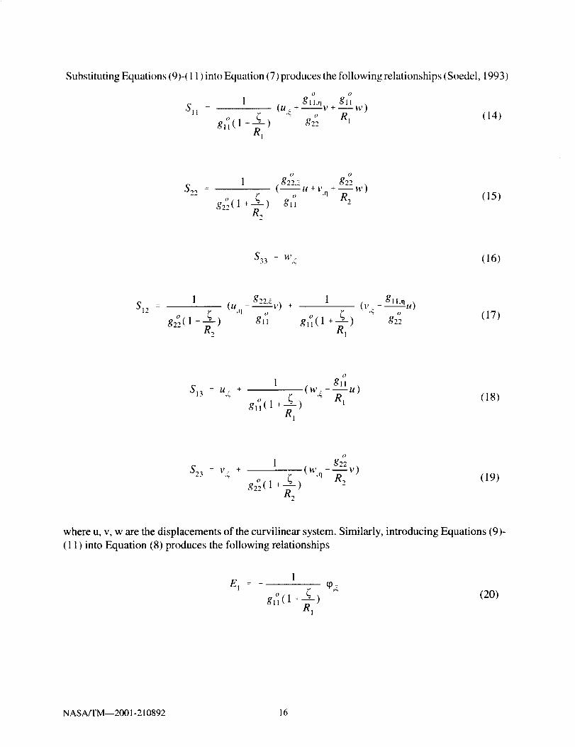
Substituting Equations (9)-( 11 ) into Equation (7) produces the following relationships (Soedel, 1993)
o o
_ gll ,,Sl I 1 (tt,_ + gll'qv +--t_)
o " R 1glL(1 + ---_-q) g2°
Rl
(14)
o O
(g_ g22 .S,,,, : 1 ..... u+v +--w)
-- g,'_(l + ¢ o 'n R_.. _2 ) gll
(15)
S = W.33 ,_ (16)
812g22._ 1
_ 1 (un - ----_v) +
g¢_'( 1 +--_-_) gll gl_(1 +---_-_)-- R2 Rl
(V _. - --gl l.q.u)
o
g22(17)
O
1 gllS13 = //- + (W:-_/g)
"_" gn(l+ ¢ '_ Rl(18)
O
1 g22 ,
$23 : v4 + (w q---v)g,°(1 +--_-_) R2
"" R2
(19)
where u, v, w are the displacements of the curvilinear system. Similarly, introducing Equations (9)-
(11) into Equation (8) produces the following relationships
1E l : _ q),¢
gl]( 1 + _'_1)(20)
NASA/TM--2001-210892 16
1E_ -
- o + _ q)'q
g22( 1 -_, )
(21)
E 3 = - ¢P.¢ (22)
3.3 Thermopiezoelectric Constitutive Equations
The constitutive equations for a linear thermopiezoelectric material employing standard
contracted notation (Nye, 1964) are
E.T r a_'V(T) 0Sa = s_ (T) cyl_ + da,.(T) E m + (23)
T ¢_.T 6,T(Dm = dm_(T) _,_ + _.,k(T) E k +Pm T) 0 (24)
or in semi-inverted form,
ET T_a = C_ (T) Sf_ - e_(T) E m - _._'r(T) 0 (25)
T S.T S,TD m -- em_(T) S_ + _._(T) E k ÷ Pm (T) 0 (26)
with the following relationships in the various piezoelectric and thermal properties arising from the
inversion,
T = cloT(T) d_(T) E me_,,(T) (27)
E,T ET a_,T(T)_.a (T) = Ca_ (T) (28)
S,T o,T T TEmk(T) = Ernk (T) - dm_(T) e_(T) (29)
S T ¢_.T TPm" (T) =Pm (T) - dm_(T) _.Ea'T(T) (30)
where C._ and s._ are the elastic stiffness and compliance tensors; d_m and e_ are the different forms
of the piezoelectric tensor due to inversion; emk is the electric permittivity tensor; % and _. are the
different forms of the coefficient of thermal expansion due to inversion; Pm is the pyroelectric
NASA/TM--2001-210892 17
constant; 0 = AT = T - T,, is the temperature difference from the current temperature T and the
thermally stress free reference temperature To; and; superscripts E, c_, S, and T, represent constant
voltage, constant stress, constant strain, and constant temperature conditions, respectively; Gt,13= 1,
.... 6; and k, m = 1, 2, 3.
3.3.1 Piezoelectric Beam
The specific form of the thermopiezoelectric constitutive equations for a piezoelectric beam
are simplified since only axial variations of the displacements are assumed,
(31)
D3 -- d31 c_1 + _;33 E3 + P3 0 (32)
or in semi-inverted form
} ]{ 1{} tCY1 Cll 0 $11 0 e31 E 1 k 1
_5 0 C55 $5 ] ! el5 0 E 3 00 (33)
03 = e31 Sl + E33 E3 + P3 0 (34)
3.3.2 Piezoelectric Plate and Shell
For the piezoelectric plate and shell, the thermopiezoelectric constitutive equations for a
monoclinic orthotropic piezoelectric material (Mason, 1950) are used,
$1
S 2
' S 4
$5
S 6
_11 S12
_12 $22
_= 0 0
0 0
0 0
0 0
0 0
s44 0 0
0 s55 0
0 0 s66
0 ol]
0 a_l
_34_' +
0 0 d31
0 0 d32
t14 0 0
dr5 0 0
0 0 0
r i}E_ +
E
_2
0_0
°l0
(35)
NASA/TM--2001-210892 18

r
_)l[ [ 0 0 0 dis
_V._-- 10 0 d24 01_91 d31 d32 0 0
(_4_" +
%1
iio:l/ it,J l,C22 E, +" _2_0
0 f'33 E 11_1
(36)
or in semi-inverted form
152
'l (_4 _ =
(35
(_6
Cll Cl2 0 0 0
C12 C22 0 0 0
0 0 C44 0 0
0 0 0 C_5 0
0 0 0 0 C66
S I
S.
S:}S,
,i
0 0 e31
0 0 e32
0 e24 0
el5 0 0
0 0 0
kl
E2 -' 0
E 3 0
0
(37)
0,1
[_ 0 0 et50 e24 0
e31 e32 0 0
S,I
,s4_ +
S_lr {}!1 0 El Pl
E22 E, + 'P2 0
0 E33 E P3
(38)
NASA/TM--2001-210892 19

CHAPTER 4
LAMINATE MECHANICS
In order to provide more general and accurate analysis of piezoelectric laminates, different
theories are implemented for the beam, plate, and shell laminates. A layerwise laminate theory is
used as the basis for the different formulations since this theory represents a generalization of other
single and higher order laminate theories (Reddy, 1993). The layerwise theory allows separate fields
to be assumed for each state variable which provides for more accurate analysis of thick laminates
and laminates containing strong inhomogeneities. In the current formulation various simplifying
assumptions and approximations are used for the beam, plate, and shell laminates.
4.1 Layerwise Laminate Theory_
The general layerwise laminate theory is formulated by introducing piecewise continuous
approximations through-the-thickness for each state variable,
N
U(X,y,z,t) __, blJ(x,y,t) " J"..)-- %t" (39)j 1
N
v(x,y,z,t) = __, vJ(x,y,t) V{(Z)j:l
(40)
N
w(x,y,z,t) =__. wJ(x,y,t) _Jw(Z)j:l
(41)
N
tp(x,y,z,t) = __. g/(x,y,t) gi_(z)j=l
(42)
N
O(x,y,z,t) = _ OY(x,y,t) _(Z)j=l
(43)
where N is the number of interpolation functions VJ and u j, v j, v/, q9, and 0j are the generalized
laminate state variables. In general, any order of interpolation functions can be used and different
interpolation functions can be selected for each state variable depending on the level of detail desired
in the analysis.
4.1.1. Beam Laminate Theory
In deriving the beam laminate theory, only axial and through-the-thickness variations of the
state variables are assumed. In addition, the displacement w is assumed to be constant through-the-
thickness. This leads to the following simplified approximations from the general layerwise theory,
NASA/TM--2001-210892 21
u(x,-,t)
N
= _ .J(x,t) _/(z)) i
(44)
w(x,z,t) = w°(x,t) (45)
N
q_(x,z,t) -- _ 4(x,t) v"(z),i _ 1
(46)
N
O(z,t) -- _ O/(t) _;(z)j:l
(47)
_(z) = [1-{ {1 (48)
where N is the number of interpolation functions WJ, _=z/h, and h represents the thickness of each
discrete layer. In this formulation, the same linear Lagrangian interpolation functions are used for
each state variable.
4.1.2 Plate Laminate Theory
The plate laminate theory is formulated with the displacement w assumed to be constant
through-the-thickness, which leads to the following simplified approximations from the general
layerwise theory,
N
u(x,y,z,t) = Y_ uJ(x,y,t) _J(z) (49)j:l
N
v(x,y,z,t) = _ vJ(x,y,t) _J(Z)j:l
(50)
w(x,y,z,t) = w °(x,y,t) (51)
N
(p(x,y,z,t) = _ q_(x,y,t) _J(z)j=l
(52)
NASA/TM--2001-210892 22
0(z,t)
N
j 1
(53)
_(z) = [1-_ _] (54)
where N is the number of interpolation functions _J and _=z/h. For the current plate laminate theory,
the same linear Lagrangian interpolation functions are used for each state variable.
4.1.3 Shell Laminate Theory
The shell laminate theory combines linear displacement fields through-the-thickness of the
laminate for the displacements u and v (along the _ and 1"1axes respectively) with layerwise electric
potential and temperature fields through the laminate, consisting of N discrete continuous segments.
Consequently, the present shell theory is specialized for modeling the deformation of thin and
moderately thick piezoelectric shells, while maintaining the capability to capture the through-the-
thickness electric and thermal inhomogeneities. The various field variables are approximated by the
following form,
u({,q,_,t)= u°(¢,rl,t) + _[3¢(_,n,t) (55)
v({,n,¢,t)-- v°({,rl,t) + ¢[3n({,n,t) (56)
w({,q,¢,t) = w°(¢,q,t) (57)
N
+({,n,;,t)-- wJ(;) (58)j=l
N
O({,rl,_,t )= y_ _({.rl,t ) qg(_) (59)j=l
_(_) = [1-4 _] (60)
where N is the number of interpolation functions @, _=_]h, and [3_and 13n are the flexural rotation
NASA/TM--2001-210892 23
angles. The same linear Lagrangian interpolation functions hu(_,) are used for the electric potential
and temperature state variables.
4.2 Generalized Laminate Matrices
The next step in the development of the formulation is the introduction of the layerwise
approximations into the variational form of the equation of motion and the electrostatic equation
(Equation 3). By performing an integration through-the-thickness, the dependence of the through-
the-thickness coordinate can be separated from the in-plane coordinates into generalized laminate
matrices for the density, stiffness, piezoelectric, dielectric permittivity, thermal expansion, and pyro-
electric properties.
4.2.1 Beam Laminate Matrices
The equivalent variational form is derived by substituting Equations (4), (5), (20), (21), and
(31 )-(34) into Equation (3), and integrating through-the-thickness,
tl tl
_f,_ , fPll iim 6u dx + 1033_i; 8w dx +k _ 1 m : 1
X X
_ f(D,,,,a. _ Oa.* ,_ ,k l m:l "_.i -dx + D55 um 6u )dx +
II
EfB, ow ,Oaw fss ( -- auk+ u -- ) dx +k=l 0X C_X A55
X X
dw d6w
Ox Oxdx +
k 1 m:, _X + 0"-;A"
-- 6q¢" ) dx -
ll II II k Ogu kZ E fo*'_m5_*d_33 Z f(A,k=l m 1 k 1 O X
X X
P3 k 6q) k ) dx
=ft i 6uidF + fq 6q_dF
v vp
(61)
NASA/TM--2001-210892 24

in which the dependence of the z-coordinate has been separated into the generalized density matrix
[p], the stiffness matrices [A], [B], [D], the piezoelectric matrix [E], the dielectric permittivity matrix
[G], the thermal expansion matrix [A_], and the pyroelectric matrix [P3].
The laminate density matrices are
kFtl
Pll = Y_I 1
f: b p _k(z) _'(z) dz (62)
L
P33 = Z f b p dz (63)1_,1 Z
the laminate stiffness matrices are
A55 = _ f b C55 dr, (64)l_-1 z
L_. OW_(z)
Bss = _, f b Cs5 _ dz (65)l: t : " Oz
Ol_ m = E f. b Cll_l/k(z) _/m(_,) d_ (66)l=1 -
L
I") km f_"-'55 = _ b C55 O_1*(z) OuF(z) dz (67)
The piezoelectric laminate matrix is
L
--E f. b e3, V*(Z) ovm(z) dz (68)l._ . Oz
The dielectric permittivity laminate matrix is
L cqv_'(z) OV"(z) dz (69)G3_'m = Z f.b_33
=_ _ 8z Oz
NASA/TM--2001-210892 25

The laminate thermal force vector is
L
, fA_ : y_ bX 1/ I
(70)
The laminate thermal electric displacement vector is
L
pk f3 : _ bP3 @ _J(z) OVk(z) dzI: 1 O_,
X
where L is the number of plies and b is the width of the beam.
(71)
NASA/TM--2001-210892 26

4.2.2.PlateLaminateMatrices
Theequivalentvariationalform is derivedby substitutingEquations(4), (5),(24)-(25),and(36)-(40)into Equation(3), andintegratingthrough-the-thickness
N
N N
f km k km_m_vk)dA + f 033_4.,_wd A__, (011 ii "8H + 022
k : 1 m _ 1A A
N N
ZZf,_,mm .,,,,,,,,e, ,,,e,�ill U,x _ll.v + "*12 _ Ig.v Ol',y + 1',3, Oil i, ) +k:l m=l
A
m k me k me k me k --kin me kA_6"(u,. BUy + U.y oua.+ u,. or.,.+ v,. otG.) + "_22 V,y OVy +
k6 m e k m e k m k m e kA (u v ov_ + v v our+ v_.Svv+ v v ovv) +
Akin. ,,18 k ., e k me k ., e X66 (lgy bly + Uy OVa + V,. OV,. + Va. OU.y) }dA +N
f B" + w av") +B_(u"aw + w au "1) +( 44(_"aw,, ,,. .,. ..,.m_l " "
A
B45m( u m 8_,y + v m 8W.,. + Wa 8V m + W..,8U " ) } dA +
{C44Wv614' + C45(wvfwv + w v614',:) + C5514'rrwr } dAfA
N
f {DkmVm_vk + r..km_, m k m_lik r_km m_llk +44 /-345 tH _,' + l' ) + /-355 H
k:l m=lA
r.,km me k Eking32I, m k+ V,y fi_ + E_6( m k m kU sSq_ + v_Sq_) +/_31 U_. Oq)
Ekm me k r, km me k31 q) OU.r + E'32 (P OV,y + E:6 ( m k m kq) Buy + q_ 8v_)
...,,kin me, k .-., km me k-- O1 _ _._ O_ ,m -- 022 (p,y Oq),y - Gff_ _"8_* } dA
N
Z f {- x;'a.: - a;a_,r'. + P?Sq)_ + P26q)., m. + P_6q_ m } dAm=l
A
F Fp
(72)
in which the dependence of the z-coordinate has been separated into the generalized density matrix
[P], the stiffness matrices [A], [B], [C], [D], the piezoelectric matrix [E], the dielectric permittivity
matrix [G], the thermal expansion matrix [A], and the pyroelectric matrix [P].
NASA/TM--2001-210892 27
The laminate density matrix is
km
9ij = __,I 1
f 9 _k(z) _'"(z) dz (73)
for ij = 11 and 22, while
L
p3_=E fpd=/=1
(74)
the laminate stiffness matrices are
Akinij = Z
l 1f cij _k(z) _"(z) d" (75)
forij = 11, 12, 16, 22, 26,44, and 66;
L
Bij = Y_ C o dzt:l Oz
(76)
L
c,-,:E f c,,d:l:l "
(77)
L
Dijkm=Z f Ci_0¢(:) 0_(:) &l= _ Oz 3z
.7.
(78)
for ij = 44, 45, and 55. The laminate piezoelectric matrices are
L
km f (_l].lm ( z ) &Eij : Z eij tltk(z) 3Z1:1
(79)
km fEij = Z eij _lm(z)I= 1 OZ
_m(z) d- (80)
NASAFFM--2001-210892 28

for ij - 31, 32, and 36. The laminate dielectric permittivity matrix is
km
G,; = F_, f _,j Vk(:) V"'(:) d:I=1
2,
(81)
for ij = 11 and 22, while
L O_k(z) o_m(=) d:km
Z
(82)
The laminate thermal force vector is
Lk
A, : Z f )_i 14/j Oj It/k(_,)NZ,l=l
(83)
for i = 1 and 2. The laminate thermal electric displacement vector is
k
P, =_ f p, _,_%.,v_(:)d:l=1
(84)
for i = 1 and 2, while
L &g_(z)e; : Z f p3w_o_ d:l:l c3z
(85)
where L is the number of composite plies and piezoelectric layers.
4.2.3 Shell Laminate Matrices
The equivalent variational form is derived by substituting Equations (11 ), (12), (24)-(25), and
(40)-(45) into Equation (3), and integrating through-the-thickness
NASA/TM--2001-210892 29

{ (p'a 17,,.4
(p_a"
N
_-" f { (A,1SI ° + AI2S,[ + Bllkl
j 1 ,4
" A c o(AI2S 1 + 220, + Bl2k I +
(A44S4" + ES4--__ )as4 ° + (A66S6 °o
g_L
+ pef3_) 8u o + (9,4 i; o
+
+ Oef3,l)&," + pa_i;°Sw°+
+ pD_.) 5[3 }d_dr I +
o,2k +Ej,¢ A 0J)as?+
B22k 2 + E_2qfl A_OJ)aS2 ° +
+ O66k 6)as: + (B66S:' + O66k 6)ak 6} +
(B,,S, ° + B,2S2 ° + D,,k, + D,zk 2 + E_,ff_ - fk_Oi)ak, }d_dq +
" " ^J " £_oJ)&(B12S I + B22S 2 + D12k t + O22k 2 + E32q) / - _ . +
s° ,p'; ,.-- + At- +{(E 5o - G[_ ,,, o )5q_'4
j:l t=l .4 glt (gll)- gll
(ES4 S: ,* q_,*n jk(F *- G22_ + P )aq) +o O
( ofg22 gll - g22
(EJlSI° + E/2S ° + EJ, k, + Ef._.k2 -GJkq_ k33+ PJ*Ok)aq¢}d_drl
I" VP
(86)
in which the dependence of the z-coordinate has been separated into the generalized density matrix
[p], the stiffness matrices [A], [B], [C], [D], the piezoelectric matrix [E], the dielectric permittivity
matrix [G], the thermal expansion matrix [A], and the pyroelectric matrix [P].
The laminate density matrix is
L
10A o o f= gllg22 E pd_ (87)
/::1¢
L
oB= o o fgl,g22 _-, _pd_
c
(88)
L
o o E f_2od_pD = gllg22
l=1¢
(89)
NASA/TM--2001-210892 30

The laminate stiffness matrices are
L
Aij =gllg2 ° Z f Cijd_l 1
(90)
for ij = 11, 12, 22, 44, 55, 66
L
°°E fBij = gllg22 _I:l
(91)
L
o o fD j = gllg22 E _2Cijd_I=l
(92)
for ij = 1 i, 12, and 22. The laminate piezoelectric matrices are
L
k o o fEij = gllgZ2 Z j eij Vk(_)d_
1=1
(93)
for ij = 14, 15, and 24.
L
, o o f 0_k(_) d_Eij = gllg22 Y_l:l eij O_.
(94)
L auk({)d{Ei) : gl°lg2°2 E f {eij1:i a_
<.
(95)
for ij = 31, 32, and 36. The laminate dielectric permittivity matrix is
L
Gij = gl 1 g22 Z F.ijl_l
(96)
for ij = 11 and 22, while
L av*(_) 0vm(_) d_G37 = g ll g22 E f g33 (97)
NASA/TM--2001-210892 31
Thelaminatethermalforcevectoris
L
-77 ,, ,, fAi -- gllg22 Z _'i _'(_) d_J1 1
(98)
L
3? o o f, = gllg22 __, _')_i _k(_) d_l=1
(99)
for i -- 1 and 2. The laminate thermal electric displacement vector is
j_Pi k'' = g,'ig,J2 _ Pk Vk(_ ) V"(_)d_
l=l(100)
L avk(_) _(_) d_pkm o o__,f3 = gll g22 P3l:l O_
(101)
for i --1 and 2, while where L is the number of composite plies and piezoelectric layers.
NASA/TM--2001-210892 32
CHAPTER5FINITE ELEMENT FORMULATION
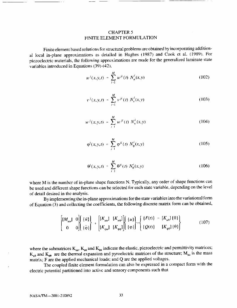
Finiteelementbasedsolutionsfor structuralproblemsareobtainedbyincorporatingaddition-al local in-plane approximationsas detailed in Hughes (1987) and Cook et al. (1989). Forpiezoelectricmaterials,thefollowing approximationsaremadefor thegeneralizedlaminatestatevariablesintroducedin Equations(39)-(42),
M
uJ(x,Y, t) uJi(t)= N. (x, y) (102)i=l
v (x,y,t)
M
= N_,(x,y)i:1
(103)
wJ(x,y,t) = (104)
M
Z W ji (t) iNw(x,Y)i:l
g/(x,y,t) = (105)
M
Z (Pji(t) iN_ (x, y)i:1
OJ(x,y.t) (106)
M
= No(x,y)i=l
where M is the number of in-plane shape functions N. Typically, any order of shape functions can
be used and different shape functions can be selected for each state variable, depending on the level
of detail desired in the analysis.
By implementing the in-plane approximations for the state variables into the variational form
of Equation (3) and collecting the coefficients, the following discrete matrix form can be obtained,
tKjJt {o(,)i[ : 03101j(107)
where the submatrices I_u, K_, and I_ indicate the elastic, piezoelectric and permittivity matrices;
I_0 and K,o are the thermal expansion and pyroelectric matrices of the structure; Muu is the mass
matrix; F are the applied mechanical loads; and Q are the applied voltages.
The coupled finite element formulation can also be expressed in a compact form with the
electric potential partitioned into active and sensory components such that
NASA/TM--2001-210892 33

l t[KLF]J[{_PF}J QF(t)}-[K_]{_pA}-[Ko]{O}
(108)
where superscripts F and A indicate the partitioned submatrices in accordance with the sensory (free)
and active electric potential components, respectively. Thus, the left-hand side includes the unknown
electromechanical responses of the structure, u and _F (i.e. the resultant displacements and voltage
at the sensors, respectively). The right-hand includes the known excitations of the structure by the
mechanical loads, applied voltages on the actuators, applied temperature loads, and electric charges.
The matrix equations can also be condensated into the following independent equations for
the sensory electric potentials,
{cpF} = [KLF] ] ([KFA] {(pA} +[K0] {0} -[K_, FF] {u} - {Q F(t)} ) (109)
and the structural displacements,
• [KFFI 1 FF[muu]{//} +([Ku ] -[KuFF]L__q_ j [K_,]){u} =
{r(,)} -( [KJ] [K__F] ' [K_oFA]+ [K,_?] ){ q)A}+
[KuT][KFF]-I FF FF _ilK 0] [K0]){0}L--_, {Q F(t) } - ( [Ku_0] [K_o_] +
(110)
5.1 Beam Element
The piezoelectric beam element formulation is obtained by incorporating the following in-
plane approximations to the state variables,
M
ug(x,t) = __,uJi(t) Ni(x) (111)i=1
M
wJ(x,t) : Y_ wJi(t) Ni(x) (1 12)i=l
M
q)J(x,t) = Z q)ji(t) Ni(x) (113)
i:1
,) ,9NASA/TM--_001-21089. 34

Ni(x) = [1-_ _1 (114)
where M is the number of in-plane linear shape functions N, _=x/L, and L is the length of the
element. A selectively reduced integration scheme is also implemented for the second stiffness term
(containing D55) of Equation (67) in order to eliminate locking.
Incorporating Equations (111)-(114) into Equation (61) results in the following specific
forms of the submatrices defined in Equation (107) for the beam element, where the submatrices are
defined using the beam laminate matrices of Equations (62)-(71 ). The mass matrix is
[Oil] 0 I[N] dx (115)
[M"u] = f, [Nlr 0 [9t3]
The stiffness matrices are
[N,,.]r[Dll][N,._]+[N]T[D55][N] [N]r[B55][N,,.] t[Xu.]: f, [N]rtB55][N,.,] [N',lr[Assl[N'"]] dx (116)
[Ku'_] = fx [N]r[E31] [N,,:] dx (1 17)
[Ko] : f_ [N]r[A_] dx (118)
[K ] : f,. [N]r[G33][N] dx (119)
[K,o0] : f, [N]r[P3 ] dx (120)
NASAITM--2001-210892 35

5.2 Plate Element
The piezoelectric plate element implements the following in-plane approximations to the
state variables,M
uJ(x,y,t) = __, uJi(t) Ni(x,y) (121)il
M
vJ(x'Y "t) = Z vii(t) Ni(x,Y) (122)i_l
M
wJ(x,y,t) = _ wJi(t) Ni(x,y) (123)i_l
M
q_(x,y,t) = _ _i(t) Ni(x,y) (124)i:l
1
Ni(x,y)---_ [(1-_)(l-q) (l+_)(l-q) (l+_)(l+q) (l-_)(l+q)] (125)
where M is the number of in-plane bi-linear shape functions N, _=x/a, and rl=y/b.
Implementing Equations ( 121 )-(125) into Equation (72) leads to the following finite element
submatrices for the plate element, where the submatrices are defined using the plate laminate
matrices in Equations (73)-(85). The mass submatrices are
[Pll] 0 0 J[Muu] = f,4 [NIT 0 [P22 ] 0 [N] dA (126)
0 0 [033]
The stiffness submatrices are
[Kll] [KI2] [KI3]]
[Kuu] = ILK12 ] [K22] [K2311
[Ex 31 x3,1]
(127)
where
[Kll ] = f {A
[N,x]r[Atl ] [N, x]
[N]r[D55] IN]
[N,_]r[A16 ][N,v] + [N,,]TIA16 ][N,_] +
[N,y]T[A66 ] [N,y] } dA
(128)
NASA/TM--2001-210892 36
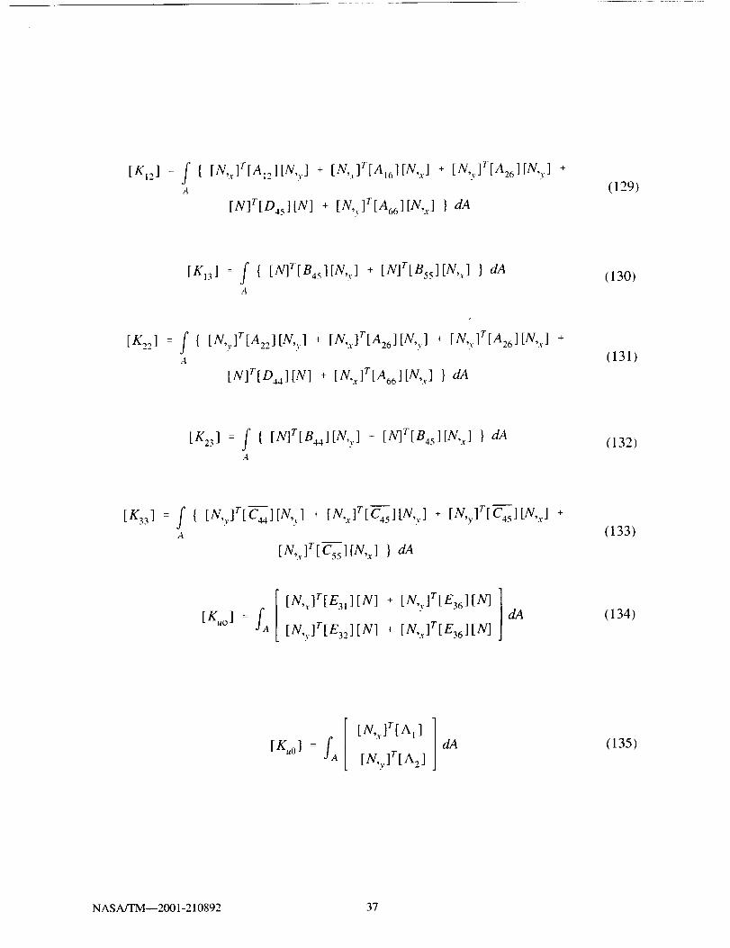
[KI2] = f { [N,x]T[AI2][N,r] + [N,x]T[A16][N,x ] + [N,v]T[A26 ][N,,,] +A
[N]r[D45] [N] + [N,y]T[A66 ] [N, x] } dA
(129)
[K13 ] = f { [N]T[B45][N,,.] + [N]r[B55][N,x] } dAA
(130)
[K22 ] = f { [N,,,]T[A22][N,y] + [N,x]T[A26][N,y] + [N,,.]T[Az6][N,x] +A
[N]T[D44 ] [N] + [N,x]T[A66 ] [N, x] } dA
(131)
[K23 ] = f { [N]T[B44][N,,,] + [N]T[B45][N,x ] } dAA
(132)
[K33] = f { [N,_]r[C44][N,,,], . + [N,,.]r[C4s][N,,]._ , + [N,_]r[c4S][N,,.],. . +A
[N,xlr[C_55][N,x] } dA
(133)
[x] : fa[N,x]r[E31][N] + [N, vlr[E36][N]
[N,y]r[E32][N] + [N,_lr[E36 ][N]
dA (134)
[_o] : fa[N,x]r[Al]
[N,y]r[A2 ]
dA (135)
NASA/TM--2001-210892 37

f { [N,xlr[Gl,l[N,x] + [N,,.]r[Gzzl[N,v] + [N]r[G331[N] } dA (136),4
[K_°] : fa { [N'']r[P1] + [N'v]r[P2] + [NIt[P3] } dA (137)
5.3 Shell Element
The piezoelectric shell element implements the following in-plane approximations to thestate variables,
M
uj°(_,rl,t) = _ uj°i(t) N i(_,rl) (138)i=l
M
= _3_,(t)N i(_,q) (139)i=1
M
(p"(_,rl,t) = _ (pmi(t) N i(4,q) (140)i:l
M
0'n(_'l] "t)= Z omi(t) N ;(_,q) (141)
i=l
1
Ni(_,q) = -_
(1-_)(l-q) - (1-4)(1 _q2)It!
(1 +_)(1 -q) (1 +_)(1 _q2)
(l+_)(l+rl) - - (1-_2)(l+q)
(1 -_)(l +q) - - (l -_)(1 _q2)
(1 -_2)(1 -1])
(1 -_:) (1 -q)
(l +_)(1 -¢)
(1 -42)(1 +q)
(l -_2) (1 -q)
(1 +_)(1 _q2)
(1 -_2) (1 +n)
(1 -¢)(1 _q2)
(142)
where M is the number of in-plane shape functions N for an eight-noded Serendipity element.
NASA/TM--2001-210892 38
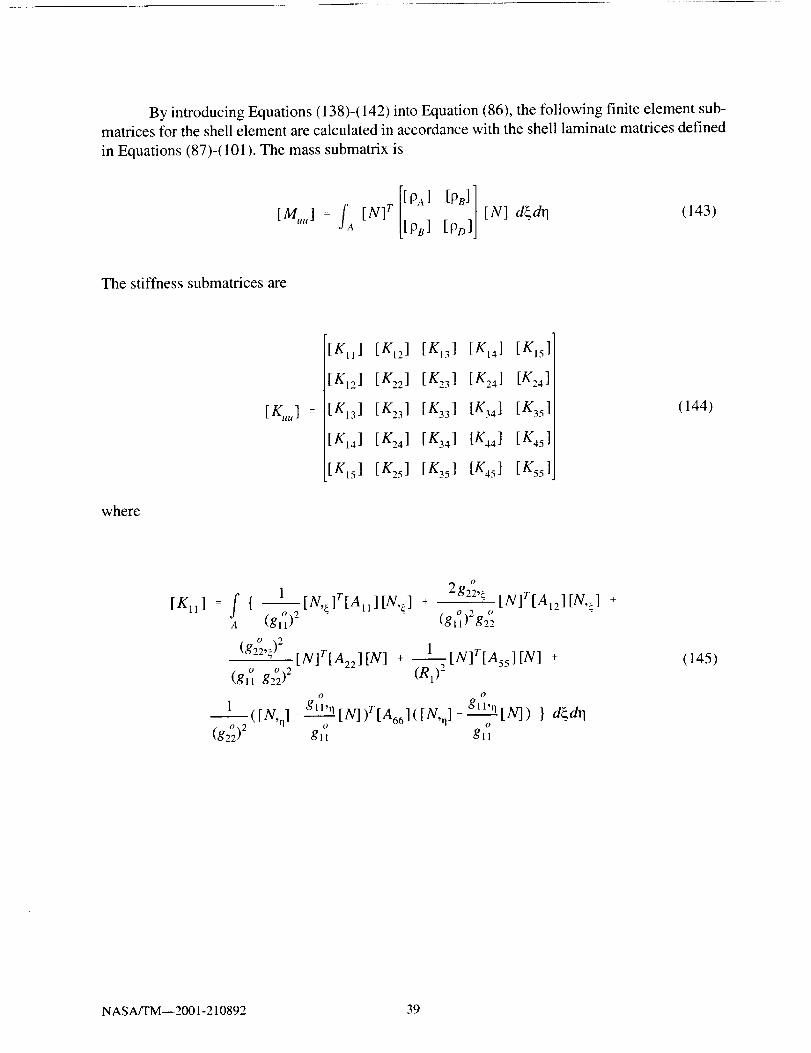
By introducingEquations(138)-(142)intoEquation(86), thefollowing finite elementsub-matricesfor theshellelementarecalculatedin accordancewith theshelllaminatematricesdefinedin Equations(87)-(101).Themasssubmatrixis
[PA] [PB]][M ] = fa [N]r [PB] [PDIJ [N] d_dr 1 (143)
The stiffness submatrices are
where
[KIj]
[K12]
: [K13]
[KI 4]
[KIs]
[Kt2] [Kt3] [KI4]
[K:31 [K33] [K_, 4]
[K241 [K34] [K,4]
tx'2,J tx35 K45J
[Kls]]
[K241
[K35]
[K45]
[K55]
(144)
[Kll] f { 1 2g22,_: _[N,a]r[All][N,a] + _ [N]T[AI,][N,_] +O _ - - , 0,, 2 O _ -
a (gll)" tgllP g22
o 2
(g22,_) [N]T[A22][N] + I____[N]T[Assl[N] +
(g_] g22) 2 (R1) 2
O O
---_1 (IN, q] - g_l'____3_[NJlr[A66]([N,n ] - glJ'._____3_[N]) } dgdrl0 0
(g2_) 2 gli g_J
(145)
NASA/TM--2001-210892 39

[K12 ]
O
f 1: { gll,q [N,a]r[A1 ][N] + [N,e.]r[Al,][N,n ]o ", o 1 o o -
A (gll)-g22 gllg22o o o
gll'n g22"_.[N]r[AI2][N] + gz2'n [N]V[A22][N,,_] +(gl'i gO)2 ,, ,,_._ gll (g22)-
o O
1 ([N,n] _ glp,_.___![N])T[A66]([N,_ ] _ gz2,____[N] ) } d_dr 1() o o O
gJl g22 gil g22
(146)
[Kt3 ] f { 1 1= --[N,_]V[AII][N] +--[N,e]r[AI2][N] +a gl°l RI gl°l R2o o
g22,_ [N]r[Al2] [N] + "- _ [N]T[A22 ][N] +0 0 0 0
gll g22 Rl gll g22 R2
_____1 ( [N,n ] -gll,q [N] )Via55 ] [N,J } d_dr 1O O
glt g22
(147)
(glOl)2[N,a]r[Btl][N,_ .] +" " (gll)2 g22A[N,¢]r[Bl2 ][N] +
O 9
(g22,_)" [N]r[B,,] [N] - 1 [Nlr[Assl[N] +o o )2 --(gll g22
O O
1 ([N,n] _ gll,q [N])T[B66]([N,q] _ gll,q [N]) } d_dr 10 0 0
g22 gl I gl!
(148)
NASA/TM--2001-210892 40

o
[Kts]- -- f { g"' o-, o [N'_-]:"[BII][N] + olA (gll)" g22 gll g22O O (I
g_2 _gll.q g22._ [N]T[BI2] [N] + " ' [N]r[B,,]__ [N, n] +
O O ") O
(gll g22)- gll (g2 °12o o
g,,,_1 ( [N,q] - g_ t"------2[N] )T[B66] ( [N,J - _'- _ [N] ) } d{dq
O O O - O
gll gz2 gll g22
o [N'_-]r[B12] [N,q] +
(149)
[ K22 ]
,,.) O
= f { (gl]'q)2oo , [N]r[AII][N] + "gll'noo , [N]r[A12][N'q] +A (gll g22)" gll (g22)"
I----_[N,q]r[A22][N,n ] + 1 [N]r[A44][N] +
(g2°2)2 (R2)_
o O
__.._.L([N,j gz2,g [N])r[A66]([N,O _ g22,_ [N]) } d{dr 1o O
gll - g-. g22
(150)
[ K23 ]
A
1
O
g22 Rl
O
o gl l,qglt'n [N]r[All][N] +
O O
gll g22 R1 gll g22 R2
1_[N,q]T[Alz][N] +
0
g22 R2
1 [N]r[A441 [N] } d_drlO
g22 R2
[N]T[AI2 ][N] +
[N,n ]r [A22 ] [N] - (151)
NASA/TM--2001-210892 41

[K24] = f {,4
o O O
gll'q g'_'_ d.gll., [N]r[Bll][N._] + .... [N]r[BI2][N] +o )2 o o )2(gll g22 (gll g22
o
l g22,_
o o [N'q ]T[Btz][N'_] + - [N,n]T[Bz2 ][N] +o o )2gll g22 gll (g22
o 0
i g,,,,,_([N,J--"_[N])r[B66]([N,n]-gll'n[N]) } d_dq
0 0 - 0 0
gll g22 g22 gll
(152)
f ll.n [N]T[Bll][N] + 2gll,n [N]T[Bp][N,q] +[K25] = { (gO)2
A (glt g22) 2 o o 9 "o o gll (g22)-
(g22°)2 [N'n]r[B221 IN'n] - . [N]T[A44 ] [NI +
O O
1 ([N,J - g2v-mA[N])r[B661([N,_] - g2v¢ [N]) } d_dr 1
(gl'] g.))2 .. .._. g22 g22
(153)
[K33] : f { 1-[N]r[A,, ][N] + 2--_[N]T[A,2][N] +a R: Rl R2
[N]T[A22][N] + 1 [N,n]r[A44][N,n] +Rg o ,,(g22)"
1 [N,_]r[Ass][N,_] } d_dr 1o 9
(gll)-
(154)
NASAfI'M--2001-210892 42

O
[K34 ] = f { 1 [N]rIB_j[N,_] + g22.4 [N]T[BI2][N] +O O O
A (gll) Rl gll g_': RjO
_ [N]r[BL2] [N,_] + g22,_ [N]T[B22] [NI +0 0 0
g_ R2 g_ g2,_ R,
1---_) [N, JT[A551[ N] } d_drlgll
(155)
g o
ta:,,]: f ¢ o ll,no [N]r[Bll][N] +
a gli g22 R_O
g11._ [N]r[Bz,][N] + I_____[N]r[B,,][N,n ] +0 0 _ 0 _
gz_ g22 R2 g22 R2
--_) [N,q]T[A44 ] [N] } d_dq
g22
1 [N]r[B12][N,_] +0
g22 R1
(156)
[K44 ] = f {[N]r[A_5][N] 1+ _[N,¢]r[Dll][N,__] +A (all)2
2 o o 2g"" _ (g"2,_)
.... [N,_]T[DI2 ] [N] + - " [N]T[D22 ] [AT] +(glOl)2 o o o 2g22 (gl I g22 )
1o [ o_([N'q]-gll,,1 N])T[D66]([N, rl]-glI,_[N]) } d_dr]
(g22) 2
(157)
NASA/TM--2001-210892 43

fx 51 - ' _ : l][N ] + 1
" g,7g/ " -0 0
o
gll'll g"_,[Njr[Ol2i[N] +.... g2,_._[N]r[D22] [As] +o o "_ 0
(gii g22)- gl! (g22)2
o o([m,,iJ - glla----Jl[lVJ)r[D66]([m,_ ] _ g22{ [NJ) } d{dq
O " 15'
gll g22 gii g22
(158)
z o 9
ix,,] : f {[NiT[A44J[N] + _ tglI,n)'_[N]T[DIIJ[N j +
a (gil g22)" "o
g,l._ [N,4ir[Dt2][N] +
g(_ (g2O)2 (g2_)2 [N,_]r[D22][N,q] +
o Og22 d - g,_,_([N'qi-_fN])SfD661(fN, n]--'"_[NJ) ] d{dq
gll g22 g2';
(159)
[E3oi ] + [Njr_g2_,: [E-_'32J[N,{] r IN] o o [N]-[N] r [Els] IN]
gtl gll g:'2 gl_ RI
[xirgi l,,,[ 3i!° _'" [E_3o2 ]o IN] + [N,o ]r [N] - [N] r [E24] [N]
gll G2° g22 g22 R2
[Njr ( [E,j] [E3, ]+ _)[N] + [N,q] r [E2a] IN] + [N,_] r [EI5] [N] d_dr I
ei (g2_)2 (gi_)--_2
O
[N] r NJ + [N, flr [N] + [N] r 22,{o o N]
o o
gli gil gil g22
[N]r [ o ,, [c#32]E24] [N] +IN] r [gll,q E31![N][N,q]r [N]o o
g22 gii g22 g2°
(160)
NASA/TM--2001-210892 44
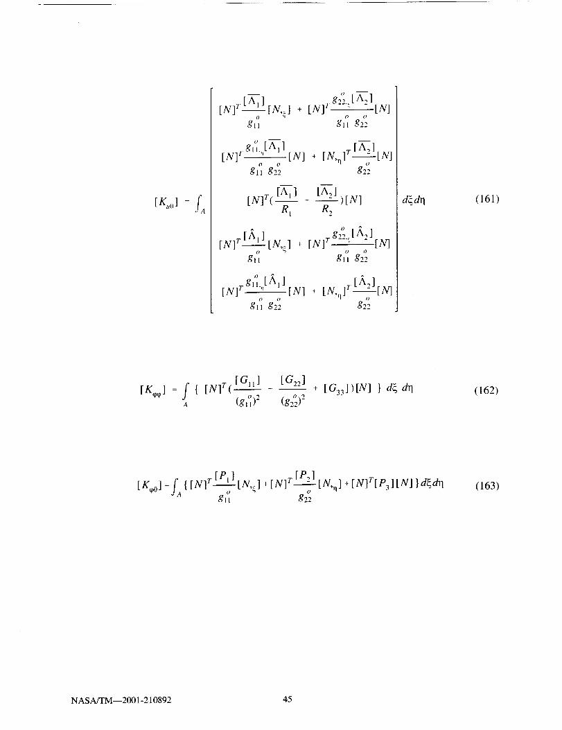
[/%] =fA
m o
[ A__]o] [ g 22" [ A _][N] r N,_] + [N] v _ "() O
gll gll g22
IN]
m mrA 1
rt_,Jr _,nIN] Tg('l''[All [N] + IN, n] -_--t_,J
0 o
gll g22 g22
[N]T([AI] + [A,]
R l R e--)[N]
^ 0
__[ g'_' [/_ ][N] r N,_] + [N] r -"_ 2o O
gll gll g22
IN]
[N] r gl AI][N] + [N,q] r [N]o O
gll g22 g22
d_dq (161)
[K ] : f { [N]T( [Gll]o* + _[G22]o
A (gll)- (g22)-
+ [ G33 ] ) IN] } d_ drl (162)
[x_o] =f_{[N]r[P']o [N,_]gll
+ [N]T [P2] [N,,1] + [N]T[P3] [N] } d_dr I0
g22
(163)
NASA/TM--2001-210892 45

CHAPTER 6
CASE STUDIES AND DISCUSSION OF RESULTS
Results from representative problems for a variety of different beam, plate, and shell
structures are presented in this section. The accuracy of the current analytical formulation is verified
with comparisons from published experimental data and other analytical models. Additional
numerical studies are also conducted to demonstrate the capabilities of the current formulation to
model the sensory and active behavior of piezoelectric composite materials.
6.1 Comparisons with Room Temperature Experimental Results
Results from previously published room temperature experimental studies are used to verify
the developed analytical formulation. The problems examined consist of a cantilevered piezoelectric
bimorph beam examined by Lee and Moon (1989) and a clamped composite plate with attached
discrete piezoelectric patches studied by Crawley and Lazarus (1991 ).
6.1. l Piezoelectric Bimorph Beam
The cantilevered piezoelectric bimorph beam problem examined by Lee and Moon (1989)
is shown in Figure 2. The bimorph is created by bonding two layers of a piezoelectric polymer
together such that the poling directions are opposite in each layer. In this configuration, the
application of an external voltage will result in a pure bending deformation. The beam has a length
(L) of 8 cm, a width of 1 cm, and a height of 220 _tm. The material properties of the polyvinylidene
fluoride (PVDF) piezoelectric polymer used in the experiment are listed in Table 1. A finite element
analysis of the bimorph beam problem is performed using the developed beam, plate, and shell
elements using sixteen elements along the length of the beam with two discrete layers through-the-
thickness. All three elements produced similar results, so only one set of predictions are presented.
Figure 3 illustrates the predicted free end (at x/L = 1) displacement obtained by applying active
voltages of between 0-500 Volts, along with the experimental results of Lee and Moon (1989). Good
agreement is observed between the predicted results of the current analytical formulation and the
experimental data.
6.1.2 Composite Plate with Piezoelectric Patches
The cantilevered composite plate problem examined by Crawley and Lazarus (1991) is
shown in Figure 4. The plate is constructed using AS4/3501 Graphite/Epoxy with a length (L) of
29.2 cm, a width (b) of 15.2 cm, and a thickness of 0.83 mm. Two laminate configurations, [0/___45]_
and [30/02] s, are examined with fifteen G-1195 piezoceramic patches with a thickness of 0.25 nun
bonded on both the top and bottom surfaces of the plate. Figure 4 also depicts the finite element
mesh used in the analysis: a 16 by 9 mesh with 8 discrete layers (one for each composite and
piezoelectric layer through-the-thickness) is used for both the plate and shell elements. Only one set
of results is presented since similar results are obtained using each element. The material properties
of the composite and piezoelectric material are listed in Table 2. The purpose of the experimental
NASA/TM--2001-210892 47

studieswasto investigatetheresultingdeflectionsof theplatewhenactivevoltagesareappliedtothepiezoceramicpatches.Theexperimentaldisplacementsalongthecenterline(y/b=0.5)of theplateareshownin Figure5 for the [0/_+45]_ plate with an applied voltage of 394 V/mm and in Figure 6
for the [30/0__]_ plate with an applied voltage of 472 V/mm. Good agreement is observed between the
predictions of the current analytical formulation and the experimental results.
PVDF
PVDF
( 8 cm
_ ____/__20_ m
1 cm
Figure 2: Cantilevered piezoelectric PVDF bimorph beam (Lee and Moon, 1989).
NASA/TM--2001-210892 48

Table 1"Materialpropertiesof PVDF piezoelectricpol_zmer(LeeandMoon, 1989).Propert_ PVDF
ElasticModulus,E (10'_Pa): 2.0
Poisson'sRatio,u: 0.29
ShearModulus,G (10°Pa): 0.8
PiezoelectricChargeConstants(10 q2 m/V):
d31 23.0
d32 3.0
4B
o 3.,i4
<D
2
•,-. 1[--
0
7
!
.......... Current Formulation
+_ Lee & Moon (1989) _-'+'/
_ _ /
+..-/
{}//
/
I I t
0 100 200 300 400 500
Electric Voltage (volts)
Figure 3: Comparison of tip deflections of a PVDF bimorph beam under applied
active electric voltages of 0-500 Volts at room temperature.
NASA/TM--2001-2 10892 49

i
I
2.5 cm
Piezoceramic Graphite/Epoxy
-- I
0.25 mm29.2 cm
• !
"! 5.1 cm
X
0.83 mm\
:_ I-- " X
-T-
I__ i
Figure 4: Cantilevered AS4/3501 composite plate with 30 attached discrete
G- 1195 piezoelectric patches (Crawley and Lazarus, 1991).
NASA/TM--2001-210892 50
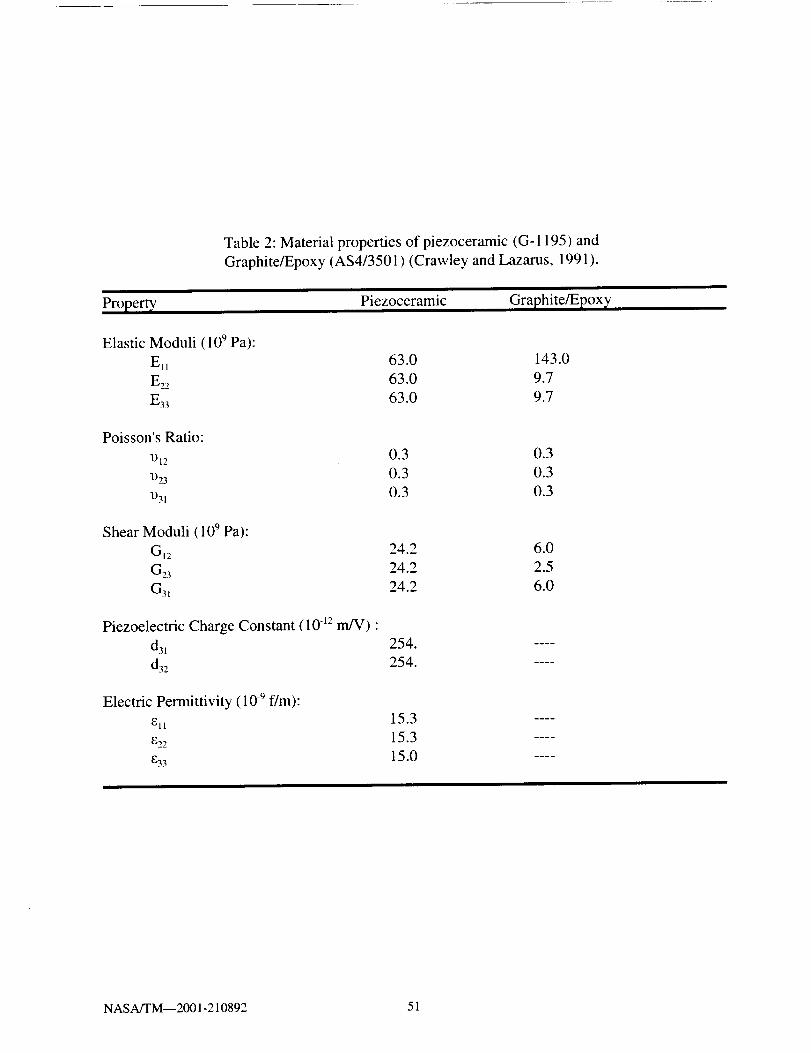
Table2:Materialpropertiesof piezoceramic(G-1195)andGraphite/Epoxy(AS4/3501)(CrawleyandLazarus,1991).
Property' Piezoceramic Graphite/Epox]¢
ElasticModuli (109Pa):Ell 63.0 143.0E22 63.0 9.7
E33 63.0 9.7
Poisson's Ratio:
DI2
1)23
1)31
0.3 0.3
0.3 0.3
0.3 0.3
Shear Moduli (109 Pa):
GI 2 24.2 6.0
G23 24.2 2.5
G3I 24.2 6.0
Piezoelectric Charge Constant (10 -12m]V) •
d3! 254.
d32 254.
Electric Permittivity (10 .9 f/m):
ell 15.3
e22 15.3
E33 15.0
NASA/TM--2001-210892 51

_D
cD
• _,,,q
° ,,,,,,q
_D,4,,,a
0.)r,.)
0.060
0.048 ii
i0.036
0.024 -
0.012
Current Formulation
Crawley & Lazarus (1991 )
/,
/O /
//
tD///
//
/
0.0000.00 0.20 0.40 0.60 0.80 1.00
Axial Length (x/L)
Figure 5: Comparisons of centerline displacement of an AS4/3501 [0/_+45]_ plate with
attached G-1195 piezoelectric patches under 394 V/mm at room temperature.
NASA/TM--2001-210892 52
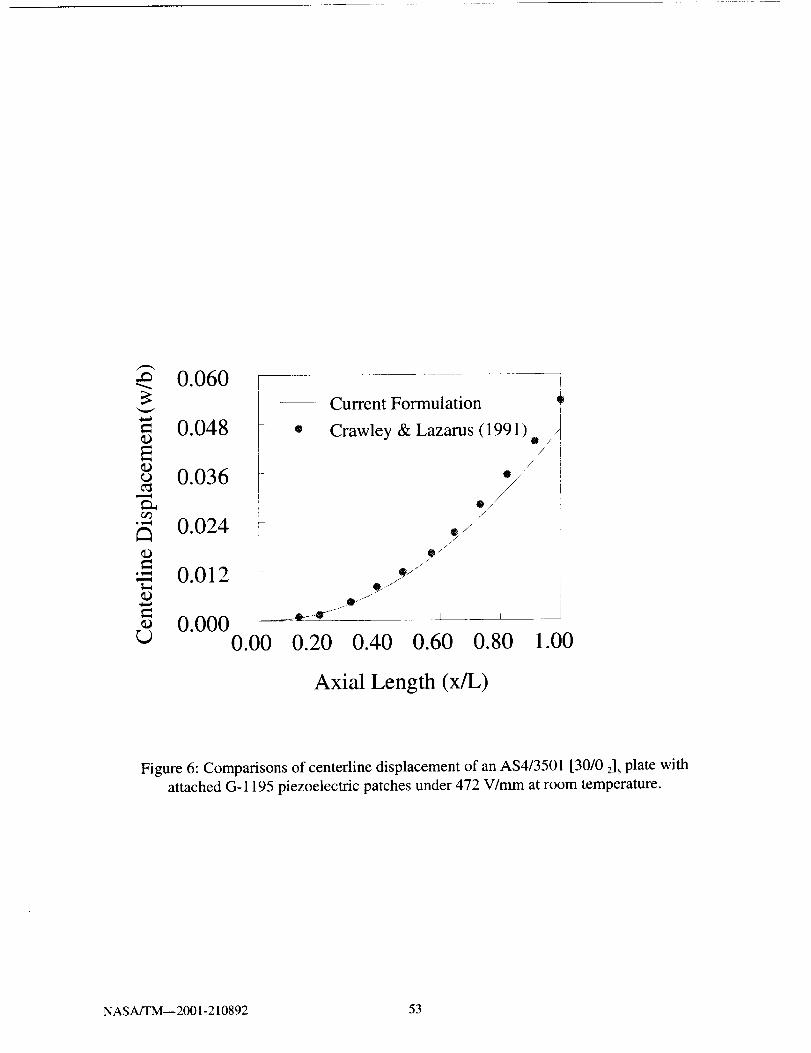
0.060 r/:
= 0.048
0.036I
•- 0.024 _
--'- 0012. -
0.0000.00
g
Current Formulation
Crawley & Lazarus (1991 )
0/¸
/
®/
/O//
i
_.---0- --II-_ I I i
0.20 0.40 0.60 0.80 1.00
Axial Length (x/L)
Figure 6: Comparisons of centerline displacement of an AS4/3501 [30/0 2]_ plate with
attached G-1195 piezoelectric patches under 472 V/mm at room temperature.
NASA/TM--2001-210892 53

6.2 Comparisons with Analytical Results for Temperature Effects
Results from previously published high temperature analytical studies are used to verify the
developed analytical formulation. The problems examined consist of a cantilevered piezoelectric
bimorph beam examined by Sunar and Rao (1997) and a simply supported composite plate with
attached discrete piezoelectric patches investigated by Ha et al. (1992). These problems present slight
variations on the room temperature experimental studies of Lee and Moon (1989) and Crawley and
Lazarus (1991 ) to analytically quantify the influence of temperature effects.
6.2.1 Piezoelectric Bimorph Beam
The cantilevered piezoelectric bimorph beam problem examined by Sunar and Rao (1997)
is shown in Figure 7. The bimorph has a length (L) of 100 mm, a width of 5 mm, and a height of 1
ram. The material properties of the polyvinylidene fluoride (PVDF) piezoelectric polymer at 27 °C
and at 77°C are listed in Table 3. An applied electric voltage of 250 Volts was applied to the
bimorph beam at 27°C to induce a bending deformation. The impact of thermal effects on the
deflection of the bimorph is subsequently examined by applying a uniform 50°C temperature
increase. The current finite element analysis is performed using 20 elements along the length of the
beam with two discrete layers through-the-thickness. All three elements (i.e. beam, plate, and shell)
produced similar results, so only one set of predictions are presented. Figure 8 shows the predicted
deflection of the bimorph along the length of the beam under an applied active voltages of 250 Volts
at 27 °C and 77 °C, along with the corresponding analytical results of Sunar and Rao (1997). Good
agreement is observed between the two sets of results, which demonstrate the impact of temperature
effects on the deflection of the bimorph beam.
6.2.2 Composite Plate with Piezoelectric Patches
The simply supported composite plate problem examined by Ha et al. (1992) is shown in
Figure 9. The [0/_+45]_ plate has a length (L) of 37.2 cm, a width (b) of 22.8 cm, and a thickness of
0.75 mm. Fifteen equally sized G-1195 piezoceramic patches with a length of 6 cm, a width of 6 cm,
and a thickness of 0.13 mm are bonded on both surfaces of the plate. Figure 9 also depicts the finite
element mesh used in the analysis: a 16 by 10 mesh with 8 discrete layers (one for each composite
and piezoelectric layer through-the-thickness) used for both the plate and shell elements. Only one
set of results is presented since similar results are obtained using each element. The material
properties of the composite and piezoelectric material are listed in Table 4. Analytical studies were
performed to investigate the capability to achieve thermal distortion management by applying active
voltages to the piezoelectric patches to eliminate the bending deflection induced by applying a
100 °C linear thermal gradient through-the-thickness of the plate (50°C on the top surface and -50°C
on the bottom surface). The predicted displacements along the centerline (y/b=0.5) of the plate along
with corresponding applied active voltages to produce this deflection are shown in Figure 10, along
with the corresponding results from Ha et al. (1992). Good agreement is observed between the two
predictions. The results demonstrate the capability to achieve shape control of the thermally induced
bending deformation by the application of increasing active voltages to the piezoelectric actuators.
NASA/TM--2001-210892 54

-250
250
PVDFPVDF
100mm
Figure 7: Cantilevered piezoelectric PVDF bimorph beam (Sunar and Rao, 1997).
NASA/TM--2001-210892 55

Table 3: Material properties of PVDF piezoelectric polymer
(Sunar and Rao, 1997).
Propert_ 27 °C 77 °C
Elastic Compliance, c,_ (109 Pa): 3.8 1.8
Thermal Expansion, a (10 .6 m/m°C): 150. 215.
Piezoelectric Constant, e31 (C/m2): 0.046 0.049
Electric Permittivity, _ (10 .9 f/m): 0.1026 0.1553
Pyroelectric Constant, P (10 .3 C/m-_°C): 0.04 0.055
Reference Temperature, TI_(°C): 27.0 27.0
0.25
0.20
o 0.15
0.10cD
.._ 0.05[..
0.00
-- Current Formulation
Sunar and Rao (1997) _*o
i
77 °Ce
/
L e
......._::_:-5_ r
-e_ -_'_ 27 °C
0 2 4 6 8 10
Axial Distance (cm)
Figure 8: Comparison of tip deflections of a PVDF bimorph beam under an applied
active electric voltages of 250 V at 27 °C and 77°C.
NASAITM--2001- 210892 56

!
Piezoceramic Graphite/Epoxy 0.75 mm
I __
0.13 mm37.2 cm
X
X
Figure 9: Simply supported AS4/3501 composite plate with 30 attached discrete
G-1195 piezoelectric patches (Ha et al., 1992).
NASA/TM--2001-210892 57
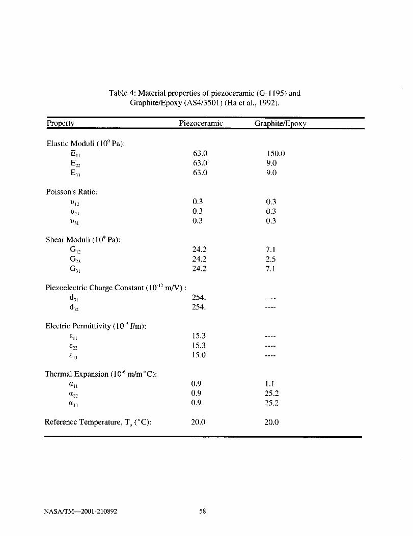
Table 4: Material properties of piezoceramic (G- 1 195) and
Graphite/Epoxy (AS4/3501) (Ha et al., 1992).
Property, Piezoceramic Graphite/Epoxy
Elastic Moduli (10 ° Pa):
Ell 63.0 150.0
E,, 63.0 9.0
E33 63.0 9.0
Poisson's Ratio:
!)12
1)23
1)31
0.3 0.3
0.3 0.3
0.3 0.3
Shear Moduli (10 ° Pa):
GI2 24.2 7.1
G23 24.2 2.5
G31 24.2 7.1
Piezoelectric Charge Constant (10 q2 m]g) •
d31 254.
d32 254.
Electric Permittivity ( 10 -9 f/m):
etl 15.3
_,, 15.3
_33 15.0
Thermal Expansi on ( 10 .6 m/m ° C):
(111 0.9
(1_ 0.9
(133 0.9
1.1
25.2
25.2
Reference Temperature, T O(° C): 20.0 20.0
NASA/TM--2001-210892 58

2.50EE= 2.00©
°¢,,_
1.50
1.00
• w...*
i
i
iFI!
i
Current Formulation
Ha et al. (1992)
0V _/31V
/
//
N f ,
//
" * 61 V0.50 _ _,\,/ /
0.00 .... _...................................................0.00 0.20 0.40 0.60 0.80 1.00
Axial Distance (x/L)
Figure 10: Comparisons of centerline displacement of an AS4/3501 [0/_+45]_ plate with
attached G-1195 piezoelectric patches under a 100 °C thermal gradient through-the-
thickness (50°C on top, -50°C on bottom) with 0, 31, and 61 V applied active voltages.
NASA/TM--2001-210892 59

6.3 Comparisons with a Commercial Finite Element Analysis Program
Evaluations of the developed analytical formulation for both the sensory and active responses
are verified with corresponding results from a commercial finite element analysis program,
ABAQUS (1996). In order to represent the location of piezoelectric layers, the standard laminate
notation is expanded, such that the piezoelectric layer is indicated by the letter p. The problem
examined consists of a Carbon/Epoxy composite plate with an attached layer of piezoceramic
material. The [0s/p] plate has a length (a) of 50.8 mm, a width (b) of 25.4mm, and a height (h) of
5.08 mm, as shown in Figure 11. The plate is clamped on one side and is subjected to a uniform
thermal load of 50°C. The material properties used are listed in Table 5. A 20 x 10 mesh with two
discrete layers (one for the Carbon/Epoxy and one for the piezoelectric layer) is used for both the
plate and shell elements from the current formulation, while a 10 x 5 x 2 mesh is used for the 20
noded continuum elements in ABAQUS. Only one set of results is presented for the current
formulation, since similar results were obtained for both the plate and shell elements. Pyroelectric
effects are intentionally neglected (i.e. set to zero) in the current formulation, since ABAQUS
neglects such effects.
6.3.1 Sensory Mode
The piezoelectric layer can be utilized in either a sensory or active mode. In the sensory
mode, the piezoelectric layer is free to develop a corresponding electric potential in response to the
thermally induced deformation of the plate through the direct piezoelectric effect. The resulting
displacements along the centerline of the plate (along y/b = 0.5) are shown in Figure 12, while the
corresponding electric potentials which develop in the piezoelectric layer are shown in Figure 13.
There is good overall agreement between the current formulation and the ABAQUS results. The
differences in the sensory electric potentials arise due to the consideration of the through-the-
thickness Poisson's effect in ABAQUS, which are neglected in the current formulation. In typical
health monitoring applications, these sensory voltages would be used to provide the essential
feedback necessary to infer the current state of deformation in the structure.
6.3.2 Active Mode
The piezoelectric layer can also be operated as an actuator by applying a voltage differential
to the piezoelectric layer and utilizing the converse piezoelectric effect to produce a corresponding
structural deformation. Figure 14 shows the centerline deflection (along y/b = 0.5) for three different
applied electric potentials (0, 250, and 500 Volts). Good agreement is observed between the current
formulation and the ABAQUS predictions. The results also demonstrate the potential of piezoelectric
actuators to completely alter the initial thermally induced deformation of the plate by the application
of increasing electric potentials in order to achieve thermal shape control.
NASA/TM--2001-210892 60

Y
//
/
/
/
/
/
, ,
b = 25.4 mm
Piezoceramic Carbon/Epoxy
a = 50.8 mm >
h = 5.08 mm
X
m
Figure 11: Clamped Carbon/Epoxy composite plate with an attached
piezoceramic layer.
NASA/TM--2001-210892 61

Table 5: Material properties of piezoceramic and Carbon/Epoxy.
Property Piezoceramic Carbon/Epoxy
(Daniel and Ishai, 1994)
Elastic Moduli (109 Pa):
Ell 69.0 142.0
E_ 69.0 10.3__
E33 69.0 10.3
Poisson's Ratio:
DI2
1)23
1)31
0.3 0.27
0.3 0.27
0.3 0.20
Shear Moduli ( 109 Pa):
Gl2 26.5 7.20
G23 26.5 4.29
G31 26.5 7.20
Piezoelectric Charge Constant (10 -_z m/V) •
d31 - 154.
Electric Permittivity (10 9 tim):
_1_ 15.05
_,, 15.05
_33 15.05
Thermal Expansion (10 -6 m/m°C):
_tH 1.2
a22 1.2
Reference Temperature, T O(°C): 20.0 20.0
NASA/TM--2001-210892 62
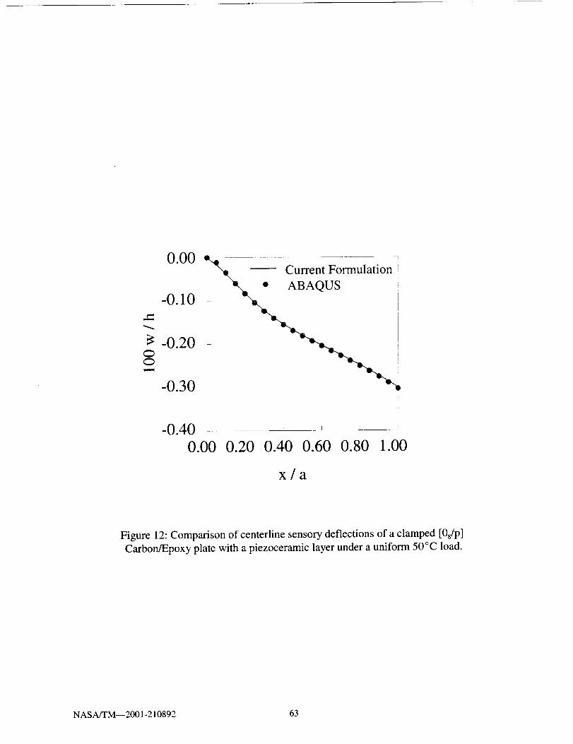
OO
0.00
-0.10
-0.20
-0.30
-0.400.00
k . •
o uaioni I I
0.20 0.40 0.60 0.80 1.00
x/a
Figure 12: Comparison of centerline sensory deflections of a clamped [08/p]
Carbon/Epoxy plate with a piezoceramic layer under a uniform 50°C load.
NASA/TM--2001-210892 63
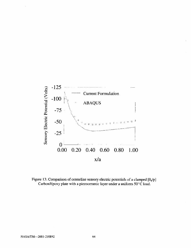
-125ro _ Current Formulation
_= -100 .....•-_ ',_ : ABAQUS= \_' 75O
.r-•_ -50
_' -25O
\• _!;ii:i i_! ii!i_ iiiili; !_i_ ,iiiii! _iiiii!_i_i_i iiiii _ii!iii ii!ii :i_ii!_:_i_ii_iiii;i ....
i ........ I i
0.00 0.20 0.40 0.60 0.80 1.00
x/a
Figure 13: Comparison of centerline sensory electric potentials of a clamped [0s/p]
Carbon/Epoxy plate with a piezoceramic layer under a uniform 50°C load.
NASA/TM--2001-210892 64

..¢:
OO
0.00 ,{
-O.lO
-0.20
-0.30 -OA=OV
! . ABAQUS
.......................Current Formulation
-0.40 • ....0.00 0.20 0.40 0.60 0.80
x/a
1.00
Figure 14: Comparison of centerline deflections of a clamped [08/p] Carbon/Epoxy
plate with a piezoceramic layer under a uniform 50°C load with applied
active voltages of 0, 250, and 500 V.
NASA/TM--2001-210892 65
6.4 Additional Numerical Studies
Results from numerical studies are presented to demonstrate additional capabilities of the
current formulation to model the behavior of piezoelectric composite structures. The capabilities
investigated include: incorporating pyroelectric effects and temperature dependent material
properties into the analysis and evaluating the significance of these effects on the thermal response;
demonstrating capabilities to achieve selective shape control of thermally induced bending and
twisting deformations; assessing the improved accuracy of layerwise models in predicting thermal
stresses; and determining the influence of curvature on the sensory and active responses.
6.4.1 Pyroelectric Effects
Pyroelectric effects arise in piezoelectric material due to temperature dependent changes in
the electrical properties. This behavior is analogous to the change in mechanical strains observed in
elastic materials due to thermal expansion. In order to demonstrate the effect of incorporating
pyroelectric effects, the clamped plate problem shown in Figure 11 is re-examined incorporating
pyroelectric effects. The problem details remain the same as before except for the consideration of
non-zero pyroelectric constants in the piezoelectric material properties as listed in Table 6. The
influence of the pyroelectric effects on the centerline deflection of the plate when the piezoelectric
layer is operating in a sensory mode is shown in Figurel 5 along with the corresponding result when
the pyroelectric constant is neglected. The corresponding results for the sensory electric potential
which develops is shown in Figure 16. Both figures demonstrate that pyroelectric effects can have
a significant impact on both the displacements and electric potentials of piezoelectric compositestructures in thermal environments.
NASA/TM--2001-210892 66

Property
Table 6: Material properties of piezoceramic and Carbon/Epox]¢.
Piezoceramic C arbon/Epox y
(Daniel and Ishai, 1994)
Elastic Moduli (109 Pa):
ELi 69.0 142.0
E_ 69.0 10.3
E33 69.0 10.3
Poisson's Ratio:
!)12
1)23
1)3l
0.3 0.27
0.3 0.27
0.3 0.20
Shear Moduli (109 Pa):
GI2 26.5 7.20
G23 26.5 4.29
G31 26.5 7.20
Piezoelectric Charge Constant (10 -12 m/V) :
d3t -154.
Electric Permittivity (10 -9 f/m):
I_11 15.05
_22 15.05
_33 15.05
Thermal Expansion (10 6 m/m °C):
511 1.2
oh2 1.2
Pyroelectric Constant (10 -3 C/m 2 eC):
P3 -0.2
Reference Temperature, To (°C): 20.0 20.0
NASA/TM--2001-210892 67

0.00
-0.10
-0.20
x/a
Figure 15: Pyroelectric effects on the centerline sensory deflections of a
clamped [08/p] Carbon/Epoxy plate with an attached piezoceramic layerunder a uniform 50°C load.
NASA/TM--2001-210892 68

©>
e-03
©
"t"
¢303
O
03
-600
-450
Pyroelectric Effects
-300 -
i
- 150 No Pyroelectric Effects
o0.00 0.20 0.40 0.60 0.80 1.00
x/a
Figure 16: Pyroelectric effects on the centerline sensory electric potentials of a
clamped [08/p] Carbon/Epoxy plate with an attached piezoceramic layerunder a uniform 50°C load.
NASA/TM--2001-210892 69
6.4.2 Temperature Dependent Material Properties
The various elastic, dielectric, piezoelectric, and pyroelectric material properties of
piezoelectric materials are influenced differently by temperature variations. In addition, piezoelectric
materials also possess a characteristic limiting temperature, called the Curie temperature, beyond
which the material loses its piezoelectric properties. Thus, in typical applications the operating
temperature of piezoelectric materials must be considerably lower than the Curie temperature. In the
current study, the temperature dependent variations of an AS4/3501-6 Carbon/Epoxy composite and
a PZT-5A piezoceramic were implemented using a piecewise linear representation irr the constitutive
equations (Equations 23-26). The temperature dependence of the AS4/3501-6 moduli and ct22 are
depicted in Figure 17, while the variation of the PZT-5A properties d3L and _33 are shown in Figure
18, while ctL_, and P3 are shown in Figure 19. All properties are nondimensionalized with their
respective room temperature values shown in Table 7. The simply supported plate with discrete
piezoelectric patches examined in Figure 9 is used to demonstrate the effects of temperature
dependent material properties. Linear thermal gradients of different values are applied through-the-
thickness of the plate with the bottom surface (z/h =-0.5) fixed at 20°C and the upper surface (z/h
= 0.5) varying from 45 ° to 170°C.
The first case utilizes a combined active/sensory configuration of the piezoceramic patches,
in which the upper patches are utilized as sensors and the lower patches are used as actuators with
zero volts applied. All the piezoceramic patches are grounded on the surface in contact with the
carbon/epoxy plate. The resulting thermally induced deflection at the center of the plate is shown in
Figure 20 for different applied thermal gradients. The deflections are nondimensionalized with
respect to the total laminate thickness (H = 1.01 mm). The results show that when material properties
are assumed to remain constant with temperature, a linear variation in deflection occurs. In contrast,
a nonlinear variation in the deflection is observed when the temperature dependent properties are
incorporated. Larger discrepancies occur between the two cases as larger thermal gradients are
applied. The corresponding sensory voltages at the central piezoceramic patch on the upper surface
of the plate is shown in Figure 21. As with the deflections, the assumption of constant material
properties leads to a linear variation of the voltages, while nonlinearities are introduced when
temperature dependent properties are modeled. Closer agreement is observed in this case.
A fully active configuration of the piezoceramic patches is used to investigate the effect of
temperature dependent material properties on thermal shape control. Equal voltages are applied to
all the piezoceramics. The applied voltages required to equally minimize the deflection at the center
of the plate to zero for different applied voltages are shown in Figure 22. Once again, a nonlinear
variation is predicted by the temperature dependent case and an increasing discrepancy is observed
as the thermal gradient increases. This discrepancy corresponds to the trend observed for the center
deflection of the plate (Figure 20). Since larger deflections occur for the temperature dependent case,
this in part justifies the larger applied voltages required to minimize the deflections.
NASA/TM--2001-210892 70
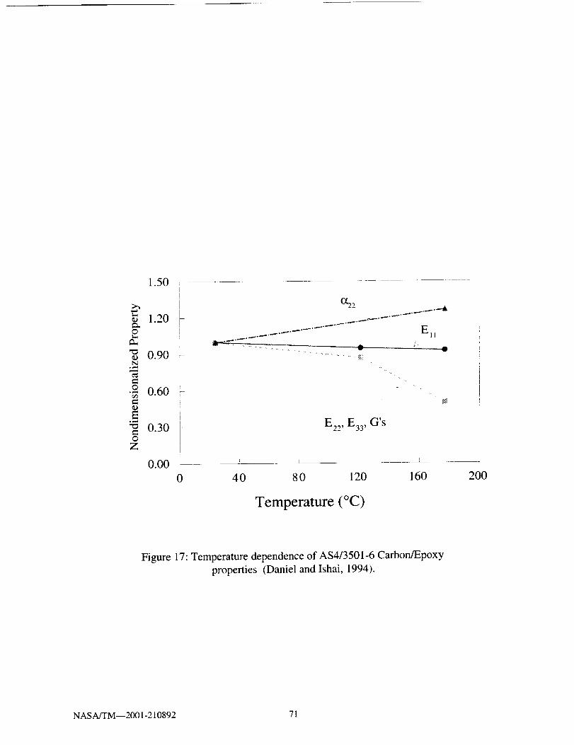
¢;
©
N°,,N
O
_DE
OZ
1.50 ? ........
1.20
0.90
0.60
0.30
!
I
EI_
..... _{
...-4t
I E22 , E33, G's
0.00 i I0 40 80 120 160 200
Temperature (°C)
Figure 17: Temperature dependence of AS4/3501-6 Carbon/Epoxy
properties (Daniel andlshai, 1994).
NASA/TM--2001-210892 71
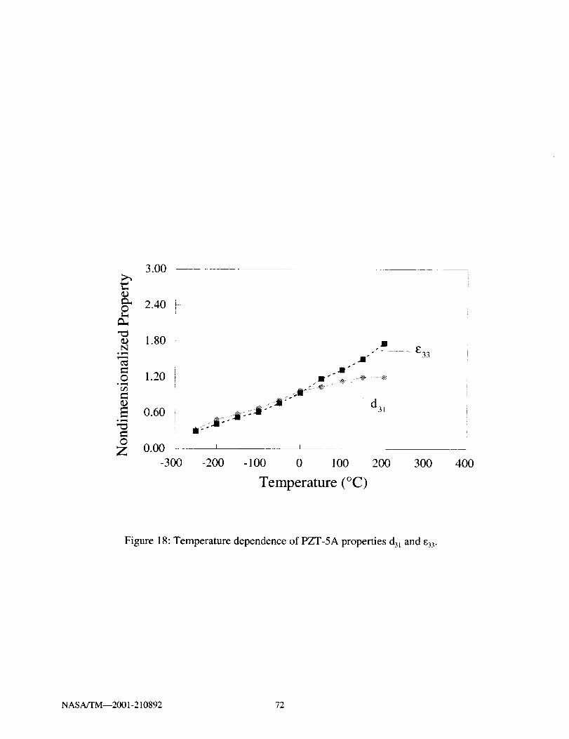
_DO
_D_q
°_,_
Or/3
E°_
OZ
3.00
2.40
1.80
1.20
0.60!i
IN
J_
.,_ ..............;iff
___ E33
0.00 i , l
-300 -200 - 100 0 100 200 300
Temperature (°C)
400
Figure 18: Temperature dependence of PZT-5A properties d31 and c33.
NASA/TM--2001-210892 72

ca,©
N• v_,,(
©ovil
r/b
E
5
I-
!
31II
IIi
2
_
O IZ o L
-300
D
P3 /'
II ....... m .... --t_7_'- -It i "IIc
i I
-200 - 100 0 100 200 300
Temperature (°C)
400
Figure 19: Temperature dependence of PZT-5A properties a_ and P3.
NASA/TM--2001-210892 73

Table 7: Material properties of piezoceramic (PZT-5A) and Carbon/Epoxy
(AS4/3501-6) composite.
Piezoceramic Carbon/Epoxy
(Daniel and Ishai, 1994)
Elastic Moduli (109 Pa):
Ell 69.0 142.0
E,, 69.0 10.3
E33 53.0 10.3
Poisson's Ratio:
u_2 0.31 0.27
u23 0.44 0.20
u31 0.38 0.02
Shear Moduli (109 Pal):
Gl2 23.3 7.2
G23 21.1 4.29
G31 21.1 7.2
Thermal Expansion ( 10 -6 m/m°C):
all 1.2 -0.9
a_, 1.2 27.0
Piezoelectric Charge Constant (10 -12m/V) :
d31 -154.
Electric Permittivity (10 -9 f/m):
E33 15.05
Pyroelectric Constant (10 3 C/m 2 °C):
P3 -2.0
Reference Temperature, T o, (°C): 20. 20.
Curie Temperature, T c, (°C): 365.
NASA/TM--2001-210892 74
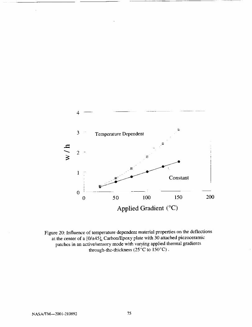
4
3 Temperature Dependent
2
tant
i I0
0 50 100 150 200
Applied Gradient (°C)
Figure 20: Influence of temperature dependent material properties on the deflections
at the center of a [0/-+45] SCarbon/Epoxy plate with 30 attached piezoceramic
patches in an active/sensory mode with varying applied thermal gradients
through-the-thickness (25 °C to 150°C).
NASA/TM--2001-210892 75
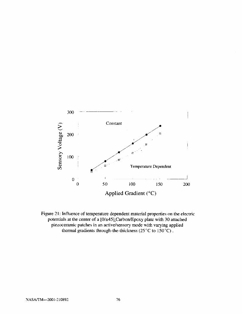
300
>
¢=
©>
©
200
lO0
0
Constant
_" ._ : ii
// _ Temperature Dependent
0 50 100 150 200
Applied Gradient (°C)
Figure 21: Influence of temperature dependent material properties on the electric
potentials at the center of a [0/+45]sCarbon/Epoxy plate with 30 attached
piezoceramic patches in an active/sensory mode with varying applied
thermal gradients through-the-thickness (25 °C to 150°C).
NASA/TM--2001-210892 76
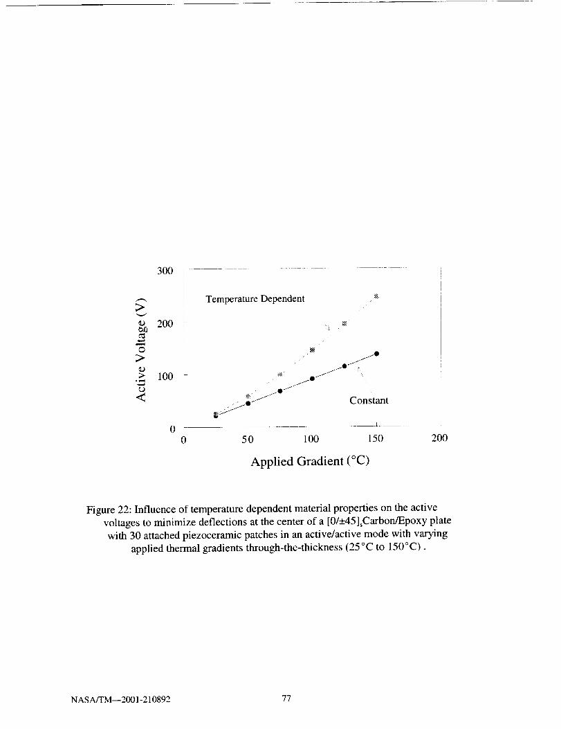
;>
e_0
4_a
©
>.
,,,,,a
<
300
200
Temperature Dependent
100 - _
. " /O f
I
0
Constant
0 5 0 100 150 200
Applied Gradient (°C)
Figure 22: Influence of temperature dependent material properties on the active
voltages to minimize deflections at the center of a [0/_+45LCarbon/Epoxy plate
with 30 attached piezoceramic patches in an active/active mode with varying
applied thermal gradients through-the-thickness (25 °C to 150°C).
NASA/TM--2001-210892 77
6.4.3 Selective Shape Control of Bending and Twisting
The potential of piezoelectric actuators to selectively minimize thermally induced
deformations is demonstrated on a clamped [453/-453] plate with attached piezoelectric patches. The
geometry and material properties remain the same as in Figure 9 and Table 4, respectively. The plate
is clamped along x=0 and a 30°C thermal gradient is applied through-the-thickness with the
piezoelectric patches operating as actuators. The temperature dependence of material properties is
neglected in this study. The resulting initial deformation is shown in Figure 23 and shows a
combined bending and twisting deformation induced by the thermal gradient. The bending
deformation can be selectively minimized by applying the same voltages to the top and bottom
piezoceramic patches. The resulting deformation when 40 V is applied is shown in Figure 24. The
twisting deformation remains unaffected and is now more apparent due to the removal of the
bending. In a similar manner, the twisting deformation can be minimized without affecting the
bending behavior. This is accomplished by applying voltages of opposite polarities on the top and
bottom surface piezoceramic patches. The deformation produced by the application of 145 V on the
top piezoceramic patches and -145 V on the bottom piezoceramic patches is shown in Figure 25. The
bending deformation is more apparent due to the removal of the twisting. In order to minimize both
the bending and twisting deformations simultaneously, the previous two cases can be superimposed.
Thus, by applying 185 V on the top actuators and -105 V on the bottom actuators, all deformations
in the plate can be eliminated as shown in Figure 26.
NASA/TM--2001-210892 78

15 -
10 "
5
-5
-10
-15 --- - 0.60
0.20 0.40 .... - _ -_ -- -- 0.800.60
0.80------ -_ 1.00Y/b 1.oo
L--~ _ _ _
.... - 0.40
Y
Figure 23: Initial bending and twisting deformation of a clamped [453/45_3]
AS4/3501 plate.with 30 attached discrete G-1195 piezoelectric patches
under a 30°C thermal gradient through-the-thickness.
NASA/TM--2001-210892 79
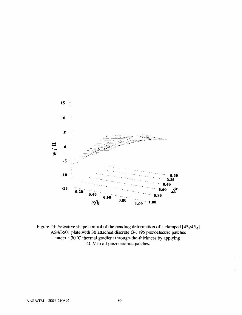
15 -
10
-5
-10
-15
- _f
oO OO0.40
0.60 _¢'-_ - -_ ..... _ 0.800.20- 0.40 0.60 ..... -
Y/b o.so ........1.00 1.00
Figure 24: Selective shape control of the bending deformation of a clamped [453/45_3]
AS4/3501 plate.with 30 attached discrete G-1195 piezoelectric patches
under a 30°C thermal gradient through-the-thickness by applying
40 V to all piezoceramic patches.
NASA/TM--2001-210892 80

15 -"
I
i
10
I
5 _
Figure 25: Selective shape control of the twisting deformation of a clamped [453/45.3]
AS4/3501 plate.with 30 attached discrete G-1195 piezoelectric patches
under a 30 °C thermal gradient through-the-thickness by applying
145 V to top patches and -145 V to bottom patches.
NASA/TM--2001-210892 81

15i
10 _
0
-5
-10
-15
"=: _ _ .... 0.20i ......... -_ -- _--- _ .... 0.40
-- _ - -_- 0.60 ,,_'_0.20_" 0.40- 0.60-.... _ --- - -'-0.80
Y/b o.8o-- ......1.00 1.00
Figure 26: Shape control of both bending and twisting deformation of a clamped
[453/45.3] AS4/3501 plate.with 30 attached discrete G-1195 piezoelectric patches
under a 30°C thermal gradient through-the-thickness by applying
185 V to top patches and -105 V to bottom patches.
NASA/TM--2001-210892 82

6.4.4 Thermal Stresses
The increased accuracy gained from implementing a layerwise laminate theory is
demonstrated by examining the thermal stresses in a cantilevered [08/p] beam. The beam is depicted
in Figure 27 and has a length (L) of 25.4 cm and a width (b) of 2.54 cm. Two thicknesses (H) are
examined; a thin beam (H = 0.1143 cm) with an aspect ratio (L/H) of -200 and a thick beam (H =
11.43 cm) with an aspect ratio (L/H) of -2. The beam is composed of eight unidirectional E-
Glass/Epoxy plies and one piezoelectric layer. The material properties are listed in Table 8. The
beam element is used to conduct the analysis using 30 elements along the length of the beam, with
one discrete layer modeled through-the-thickness for each piezoelectric and E-Glass/Epoxy ply. A
uniform temperature rise of 100°C is applied with the piezoelectric layer grounded (i.e. 0 V applied).
The predicted normal stress, g_1, near the middle of the beam (x/L = 0.5) is shown in Figure 28 for
both the thin and thick beams, along with the corresponding results predicted by classical laminate
theory (CLT). The normal stress is nondimensionalized using the equivalent laminate modulus, EH_
= 42.2 109 Pa. The CLT predicts the same stress regardless of the thickness of the beam. At this
location of the beam, there is good agreement between the current formulation and CLT regardless
of the beam thickness. The predicted normal stress, ¢_, at the free end of the beam (x/L = 1.0) is
shown in Figure 29 and shows that CLT is only accurate for the thin beam. The predicted shear
stress, ¢Y_3,at the free end of the beam (x/L = 1.0) is shown in Figure 30. The shear stress is
nondimensionalized using the equivalent laminate modulus, GL_3 = 6.3 109 Pa. The results show that
the CLT assumption of neglecting shear stresses is only accurate for the thin beam case. These
results help demonstrate the improved accuracy in stress predictions achieved by using the layerwise
laminate theory, especially for thick laminates.
NASA/TM--2001-210892 83
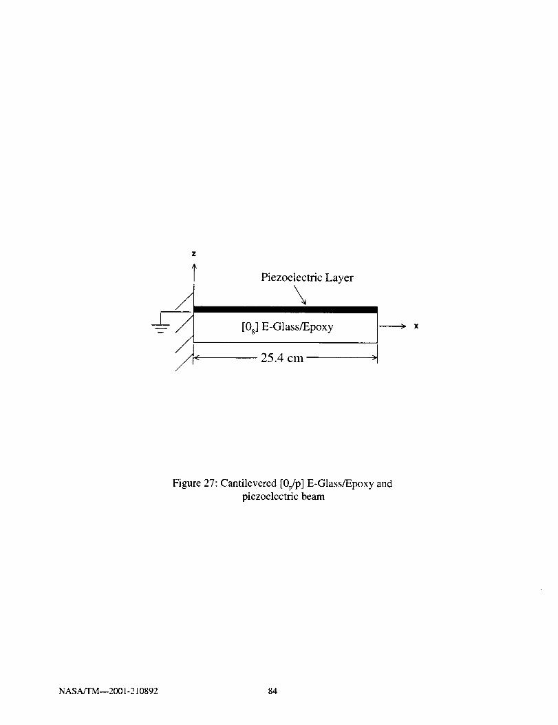
Piezoelectric Layer
\[08 ] E-Glass/Epoxy
25.4 cm
Figure 27: Cantilevered [0p/p] E-Glass/Epoxy andpiezoelectric beam
NASA/TM--2001-210892 84
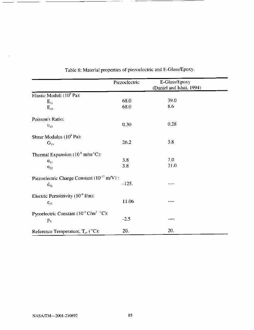
Table 8: Material properties of piezoelectric and E-Glass/Epoxy.
Elastic Moduli (109 Pa):
Ett
E33
Piezoelectric E-Glass/Epoxy
(Daniel and Ishai, 1994)
68.0 39.0
68.0 8.6
Poisson's Ratio:
1)130.30 0.28
Shear Modulus (100 Pa):
Gl3 26.2 3.8
Thermal Expansion ( 10 -6 m/m ° C):
(111
(133
3.8 7.0
3.8 21.0
Piezoelectric Charge Constant (10 12 m/V) •
d31 -125.
Electric Permittivity (10 9 f/m):
E3311.06
Pyroelectric Constant (10 .3 C/m 2 °C):
P3 -2.5
Reference Temperature, T o, ( ° C): 20. 20.
NASA/TM--2001-210892 85
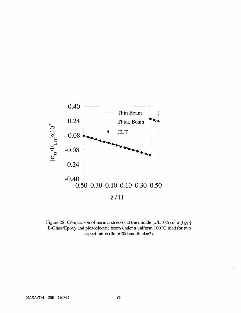
O
0.40 ....
0.24
• CLT
0.08-0.08
Thin Beam i
Thick Beam _-_*_
-0.24!
I
-0.40-0.50-0.30-0.10 0.10 0.30 0.50
z/H
Figure 28: Comparison of normal stresses at the middle (x/L=0.5) of a [0s/p]
E-Glass/Epoxy and piezoelectric beam under a uniform 100°C load for two
aspect ratios (thin=200 and thick=2).
NASA/TM--2001-210892 86

0.40Thin Beam
0.24 _ Thick Beam
+ CLT
0.08 ..
_ -0.08
-0.24
-0.50-0.30-0.10 0.10 0.30 0.50
z/H
Figure 29: Comparison of normal stresses at the free end (x/L=l.0) of a [0s/p]
E-Glass/Epoxy and piezoelectric beam under a uniform 100°C load for two
aspect ratios (thin=200 and thick=2).
NASA/TM--2001-210892 87

.d
m
4
3
2
0
-1
Thin Beam
Thick Beam
CLT
'lt
!
I
..... I
I
I
i !
' 1
,!J ........ , I
_,4"_t *,*,_*_ *J-"'*_,_'__°i.* • ,_,
! k
-0.50-0.30-0.10 0.10 0.30 0.50
z/H
Figure 30: Comparison of shear stresses at the free end (x/L=l.0) of a [0s/p]
E-Glass/Epoxy and piezoelectric beam under a uniform 100°C load for two
aspect ratios (thin=200 and thick=2).
NASA/TM--2001-210892 88
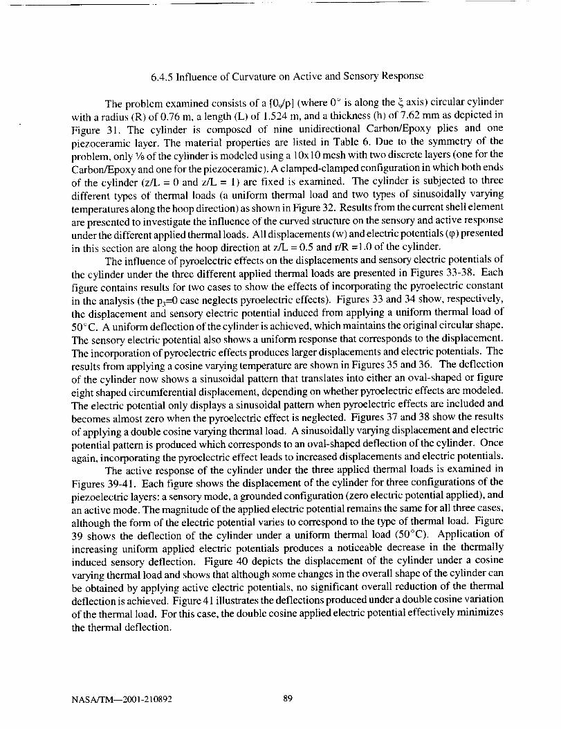
6.4.5 Influence of Curvature on Active and Sensory Response
The problem examined consists of a [09/p] (where 0 ° is along the _ axis) circular cylinder
with a radius (R) of 0.76 m, a length (L) of 1.524 m, and a thickness (h) of 7.62 mm as depicted in
Figure 31. The cylinder is composed of nine unidirectional Carbon/Epoxy plies and one
piezoceramic layer. The material properties are listed in Table 6. Due to the symmetry of the
problem, only 1/8of the cylinder is modeled using a 10x 10 mesh with two discrete layers (one for the
Carbon/Epoxy and one for the piezoceramic). A clamped-clamped configuration in which both ends
of the cylinder (z/L = 0 and z/L = 1) are fixed is examined. The cylinder is subjected to three
different types of thermal loads (a uniform thermal load and two types of sinusoidally varying
temperatures along the hoop direction) as shown in Figure 32. Results from the current shell element
are presented to investigate the influence of the curved structure on the sensory and active response
under the different applied thermal loads. All displacements (w) and electric potentials (q_)presented
in this section are along the hoop direction at z/L = 0.5 and r/R =1.0 of the cylinder.
The influence of pyroelectric effects on the displacements and sensory electric potentials of
the cylinder under the three different applied thermal loads are presented in Figures 33-38. Each
figure contains results for two cases to show the effects of incorporating the pyroelectric constant
in the analysis (the p3=0 case neglects pyroelectric effects). Figures 33 and 34 show, respectively,
the displacement and sensory electric potential induced from applying a uniform thermal load of
50 ° C. A uniform deflection of the cylinder is achieved, which maintains the original circular shape.
The sensory electric potential also shows a uniform response that corresponds to the displacement.
The incorporation of pyroelectric effects produces larger displacements and electric potentials. The
results from applying a cosine varying temperature are shown in Figures 35 and 36. The deflection
of the cylinder now shows a sinusoidal pattern that translates into either an oval-shaped or figure
eight shaped circumferential displacement, depending on whether pyroelectric effects are modeled.
The electric potential only displays a sinusoidal pattern when pyroelectric effects are included and
becomes almost zero when the pyroelectric effect is neglected. Figures 37 and 38 show the results
of applying a double cosine varying thermal load. A sinusoidally varying displacement and electric
potential pattern is produced which corresponds to an oval-shaped deflection of the cylinder. Once
again, incorporating the pyroelectric effect leads to increased displacements and electric potentials.
The active response of the cylinder under the three applied thermal loads is examined in
Figures 39-41. Each figure shows the displacement of the cylinder for three configurations of the
piezoelectric layers: a sensory mode, a grounded configuration (zero electric potential applied), and
an active mode. The magnitude of the applied electric potential remains the same for all three cases,
although the form of the electric potential varies to correspond to the type of thermal load. Figure
39 shows the deflection of the cylinder under a uniform thermal load (50°C). Application of
increasing uniform applied electric potentials produces a noticeable decrease in the thermally
induced sensory deflection. Figure 40 depicts the displacement of the cylinder under a cosine
varying thermal load and shows that although some changes in the overall shape of the cylinder can
be obtained by applying active electric potentials, no significant overall reduction of the thermal
deflection is achieved. Figure 41 illustrates the deflections produced under a double cosine variation
of the thermal load. For this case, the double cosine applied electric potential effectively minimizes
the thermal deflection.
NASA/TM--2001-210892 89

X
_-_-- L = 1.$24 m
_ _;___zoceramic (0.7 mm thick)
_l _ (_ Carbon/Epoxy (7.55 mm thick)
___ 1/8 of Cylinder
Figure 31 : Geometry of a [09/p] Carbon/Epoxy circular cylinder with an
attached piezoceramic layer.
NASA/TM--2001-210892 90

T=50 o C
i/'
L_
T=50 °C
- _% - ,
Y
T=25 o C
(a) Uniform T (b) T cos y (c) T cos 2 y
• i
Y
Figure 32: Different types of applied thermal loads applied to the cylinder:
a) 50°C uniform thermal load; b) 50°C cosine varying load; and
c) 25 °C double cosine varying load.
NASAfI'M--2001-210892 91

0.20 F ...........
0.10 i
I
0.00
010
__ A A _ A A A A A
p3=-2e - 4
P3=0
-0.300 30 60 90
7 (degrees)
Figure 33: Influence of pyroelectric effects on the displacements of a [09/p]
Carbon/Epoxy circular cylinder with a piezoceramic layer undera 50°C uniform thermal load.
NASA/TM--,.001-21089_ 92
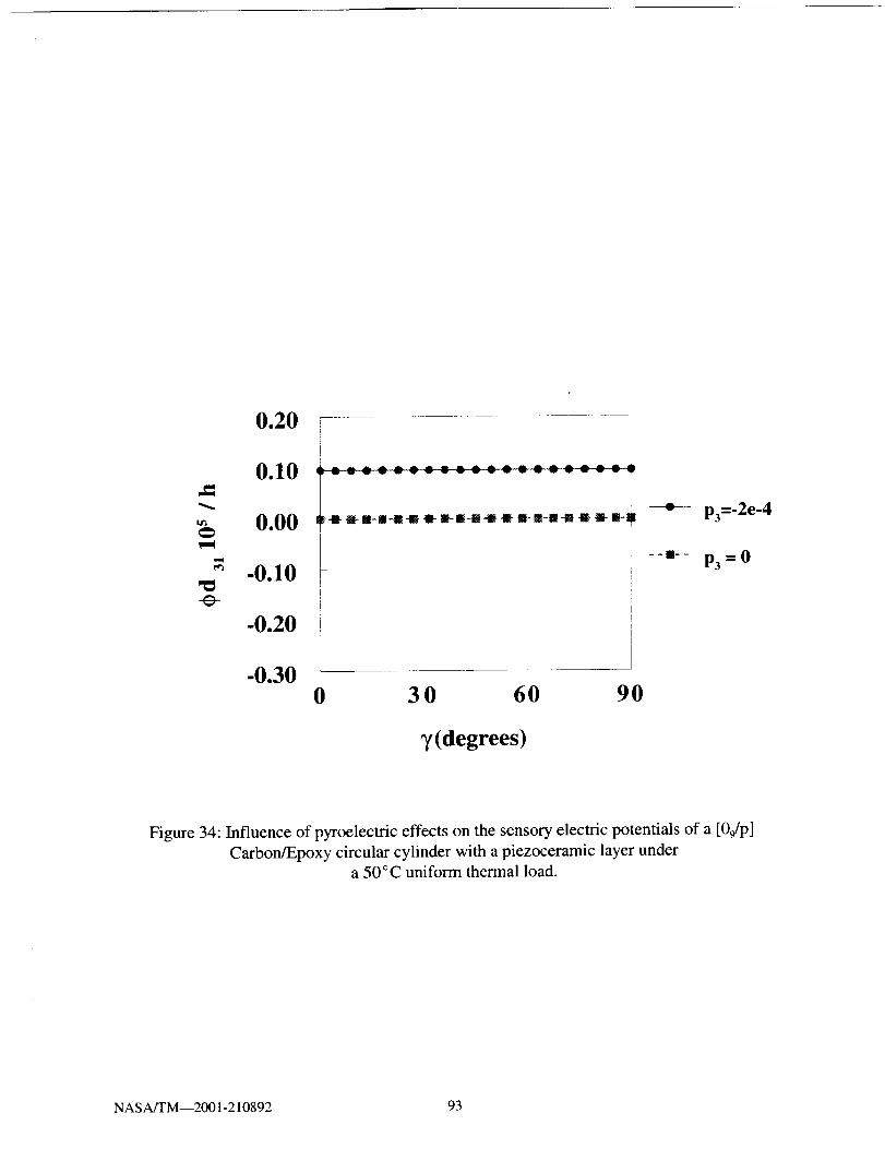
0.20
0.10
0.00
=_ -0.10
-e-
-0.20
-0.300 30 60 90
y(degrees)
Figure 34: Influence of pyroelectric effects on the sensory electric potentials of a [09/p]
Carbon/Epoxy circular cylinder with a piezoceramic layer undera 50°C uniform thermal load.
NASA/TM--2001-210892 93
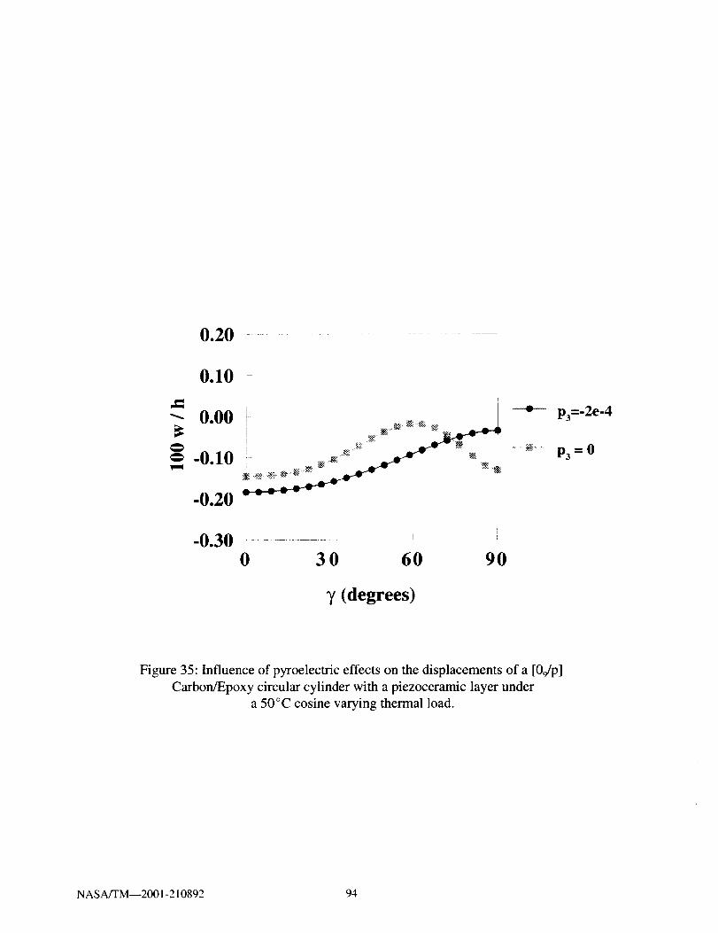
0.20
0.10
0.00
-0.30
i
_- _:. 5 _ '_
i- °°..° °°°_
0 30 60 90
_/(degrees)
p3=-2e-4
P3 =0
Figure 35: Influence of pyroelectric effects on the displacements of a [09/p]
Carbon/Epoxy circular cylinder with a piezoceramic layer under
a 50°C cosine varying thermal load.
NASA/TM--2001-210892 94

0.20
0.10
0.00v-¢
:_ .0.10 I-e- l
-0.20
-0.300 30 60 90
T (degrees)
Figure 36: Influence of pyroelectric effects on the sensory electric potentials of a [09/p]
Carbon/Epoxy circular cylinder with a piezoceramic layer under
a 50°C cosine varying thermal load.
NASA/TM--2001-210892 95
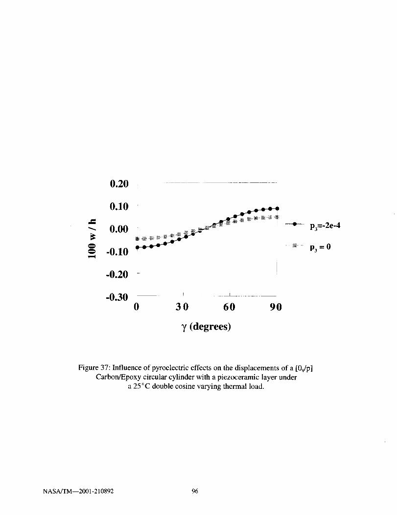
0.20 ...............
0.10
-- 0.00
-0.10v-q
-0.20
-0.30 '0 30 60 90
p3=-2e-4
P3=O
7 (degrees)
Figure 37: Influence of pyroelectric effects on the displacements of a [09/p]
Carbon/Epoxy circular cylinder with a piezoceramic layer under
a 25 °C double cosine varying thermal load.
NASA/TM--2001-210892 96

"O-e-
0.20
0.10
0.00
-0.10
-0.20
-0.300 30 60 90
V (degrees)
Figure 38: Influence of pyroelectric effects on the sensory electric potentials of a [09/p]
Carbon/Epoxy circular cylinder with a piezoceramic layer under
a 25 °C double cosine varying thermal load.
NASA/TM--2001-210892 97

0.20
0.10
0.00 L
II
020 * ............ *_ .... @ .,..... v I. .,. @ @ @ @ _. _." . J
i
I i!
-0.300 30 60 90
(degrees)
Sensory
....._.....OV
-500 V
Figure 39: Comparison of displacements of a [09/p] Carbon/Epoxy circular cylinder
with a piezoceramic layer in sensory, grounded, and active modesunder a 50°C uniform thermal load.
NASA/TM--2001-210892 98

0.20 ri
ii
0.10
_ A + . ._.+ " i :
_ _
-0.20 _ J-
I
-0.300 30 6O 90
Sensory
....._ .... OV
--i-- cos2 _,
T (degrees)
Figure 40: Comparison of displacements of a [09/p] Carbon/Epoxy circular cylinder
with a piezoceramic layer in sensory, grounded, and active modes
under a 50°C cosine varying thermal load.
NASA/TM--2001-210892 99
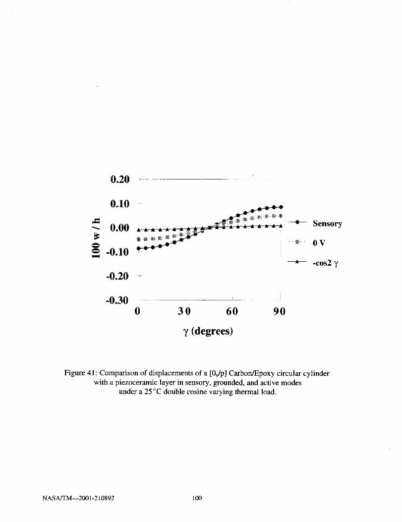
0.20 r
0.10 _ i
0.00 _ _ Sensory
_+ __ ...._ .... OV_ -0.10 _
-0.20 i
-0.300 30 60 90
-cos2 7
7 (degrees)
Figure 41: Comparison of displacements of a [0Jp] Carbon/Epoxy circular cylinder
with a piezoceramic layer in sensory, grounded, and active modes
under a 25 °C double cosine varying thermal load.
NASA/TM--2001-210892 100
CHAPTER 7
CONCLUSION AND SUGGESTIONS FOR FUTURE WORK
New analytical formulations and mechanics are developed to characterize the coupled
mechanical, electrical, and thermal behavior of piezoelectric composite materials. The coupled
thermopiezoelectric behavior is captured at the material level through the constitutive equations and
the displacements, electric potential, and temperature are introduced as state variables in the
formulation. The equations of motion are developed in both cartesian and curvilinear coordinates
and a layerwise laminate theory is incorporated to provide more accurate predictions of interlaminar
and intralaminar effects, especially for thick laminates. Thermal effects arising from thermal
expansion mismatch, pyroelectric effects, and temperature dependent material properties are
incorporated in the formulation. Corresponding finite element equations are developed and
implemented into stand alone computer programs for beam, plate, and shell elements. The accuracy
of the formulation is verified with comparisons from published experimental data and other
analytical methods. Additional numerical studies are also conducted to demonstrate additional
capabilities of the formulation to predict the sensory and active behavior of piezoelectric composite
materials. The verification and numerical studies have helped to demonstrate the effectiveness and
accuracy of the developed mechanics and finite elements. However, future experimental studies will
help to complement this work by contributing to additional verification studies.
7.1 Suggested Plan of Future Experimental Studies
In order to verify the accuracy of the developed analytical formulation in more detail, the
following plan of experimental studies are outlined. As illustrated in the previous sections, previous
researchers have conducted numerous room temperature static experimental studies along with some
limited high temperature studies. However, dynamic studies, and in particular high temperature
dynamic experiments, have received less attention. Thus, the development of an experimental setup
for conducting high temperature dynamic studies will help to more fully characterize the behavior
of piezoelectric composite materials and determine the feasibility of applying these materials in
extreme temperature environments.
A generic dynamic experimental setup is shown in Figure 39. A beam specimen with an
attached piezoelectric patch will be excited by an electromagnetic shaker and the corresponding
response of the beam measured by an accelerometer. For high temperature tests, the beam will be
placed inside an oven or furnace. The time varying responses of the beam and piezoelectric patch
are passed through various test measurement devices including signal conditioners, amplifiers, and
oscilloscopes to increase the signal strength and gain, as well as to monitor and measure the dynamic
waveforms. The time signals are then passed on to a PC based dynamic data acquisition system
which contains hardware to acquire the signals and software to calculate the frequency response of
the data. The resulting output will include the natural frequencies of the beam, the mode shapes, and
the sensor output.
A series of tests will be performed to investigate the individual sensory and active dynamic
responses of piezoelectric composite materials at high temperature. The first test configuration will
consist of a beam with a single piezoelectric patch as shown in Figure 40. A series of tests will be
NASA/TM--2001-210892 101

performedaslistedin Table9 to determinethesensoryandactiveresponsesindividually. A roomtemperaturebaselinetestwill beperformedto determinethenaturalfrequenciesof thebeamwiththepiezoelectricpatchgrounded.Thepiezoelectricpatchwill thenbe testedin a sensorymodetodemonstratethe capability to monitor modal frequenciesthroughmeasurementof the sensoryvoltages,andto determinethe effect of the sensorymodeon the natural frequencies.Next, thepiezoelectricpatchwill beconfiguredasanactuatorandelectricvoltagesappliedto measurethecapabilityto activelycontrolthevibrationof thebeam.Theseexperimentswill thenberepeatedathighertemperaturetoassessthermaleffectsonthesensoryandactiveresponses.A seriesof differentbeammaterialsfrom metalsto compositescanbestudied,aswell asdifferenttypesof piezoelectricmaterialsfrompiezopolymerstopiezoceramics,in ordertodeterminethemosteffectivesensorandactuatormaterials.In addition,thesizeandlocationof thepiezoelectricpatchcanbevariedto assesstheinfluenceof coverageareaandlocationon sensingandactuation.
Thenext testconfigurationwill consistof abeamwith two piezoelectricpatches,asshowninFigure41, to investigatecombinedsensory/activeandactive/activemodesof operation.A seriesof testswill beperformedasshownin Table10to determinecapabilitiesfor combinedsensoryandactuatoroperations.Thebaselinecasewill consistof aroomtemperaturetestwithbothpiezoelectricpatchesgroundedto determinethe natural frequenciesof the beam.A combinedsensory/activeconfigurationwill thenbestudied,in which variousvoltageswill beappliedto theactuatorpatchto reducethenaturalfrequencies,while thesensorpatchmonitorstheresponse.Thenextcasewillinvolve both patchesoperatingas actuatorsto determinewhethermultiple actuatorscanmoreeffectively reducethe beamvibrations than a singleactuator.Theseexperimentswill thenberepeatedat higher temperatureto determinethermaleffectson thecombinedsensory/activeandactive/activeconfigurations.Additional caseswith differentbeamandpiezoelectricmaterials,aswell as different sized patchesand locationswill also be studiedto determine the optimalcombinationsfor combinedsensory/activeandactive/activeoperations.
Additionalstudieswill alsobeconductedona flat platewith multiplepiezoelectricpatches(Figure42) andacurvedplatewith multiplepiezoelecuicpatches(Figure43).Theflat platewillprovideadditionalinformationon two-dimensionalgeometryeffectson sensingandactuation,aswell asto determinecapabilitiesto utilizepatchesat specificlocationsto senseandactuatecertainnaturalfrequencies.A similarstudywill alsobeperformedonacylindrical shell to determinetheeffectof curvatureonactuationandsensing.As inpreviousproblems,thebaselinecasewill involvedeterminingtheroomtemperaturenaturalfrequencieswith thepiezoelectricpatchesinoperative.Avariety of different sensorand actuatorconfigurationswill be examinedat room and hightemperatures,for differentbeamandpiezoelectricmaterials.
Throughouttheexperimentalstudies,the developedfinite elementcodeswill beusedtoprovide designguidelinesto reduce the numberof experiments.Even for the simple beamconfigurationsstudiedin Figures40and41, therea largenumberof differentexperimentsrequiredto determinetheinfluenceof differentmaterials,patchsizes,andlocations.As morecomplicatedgeometriesareconsideredin Figures42 and43, the numberof experimentaltestswill increasesubstantially.Thus,in orderto keepexperimentaltestingtime andcostsreasonable,a combinedanalyticalandexperimentalapproachis essential.
NASA/TM--2001-210892 102

Test Specimen Dynamic Measurement
• Natural Frequencies
• Dynamic Deflections
• Sensor Output
f'---AccelerometerI
Time Signals
. ,_ I1ii ii _._ _ t i _ : f i i _ _i_
II• Data Acquisition
• Spectral Analyzer
Figure 39: Dynamic experimental setup.
NASA/TM--2001-210892 103

Testing Configuration
Piezoceramic fAcceler
Shaker
Oven or
Furnace
Figure 40: High temperature test configuration for a cantilevered beam
with one piezoelectric patch to examine sensory and
active modes individually.
NASA/TM--2001-210892 104

Table 9: Series of tests for a cantilevered beam with one piezoelectric patch.
Beam and Piezoelectric Materials
Aluminum Beam [08] Graphite/Epoxy [02/90_]s
Beam Graphite/Epoxy Beam
Temp. Piezo PZT PVDF PZT PVDF PZT PVDFMode Patch Patch Patch Patch Patch Patch
Room Grounded
Room Sensory
Room Active
Elevated Grounded
Elevated Sensory
Elevated Active
NASA/TM--2001-210892 105
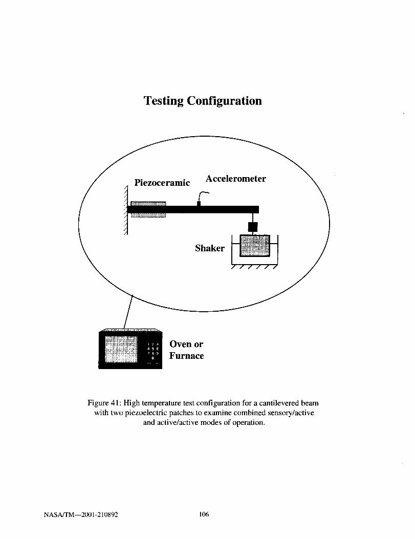
Testing Configuration
Piezoceramicccele
Shaker
Oven or
Furnace
Figure 41: High temperature test configuration for a cantilevered beam
with two piezoelectric patches to examine combined sensory/active
and active/active modes of operation.
NASA/TM--2001-210892 106

Table 10: Series of tests for a cantilevered beam with two piezoelectric patches.
Temp. Piezo.
Mode
Room Grounded
Room Active/
Sensory
Room Active/
Active
High Grounded
High Active/
Sensory
High Active/
Active
Aluminum Beam
PZT/ PVDF/ PZT/
PZT PVDF PVDF
Beam and Piezoelectric Materials
[08] Graphite/EpoxyBeam
[0,_/902] s Graphite/EpoxyBeam
PZT/ PVDF/ PZT/ PZT/ PVDF/ PZT/
PZT PVDF PVDF PZT PVDF PVDF
NASA/TM--2001-210892 107

Piezoelectric patch
I I
Figure 42: Test configuration of a flat plate with attached piezoelectric
patches to investigate two-dimensional effects on combined
sensory and active operations.
NASA/TM--2001-210892 108

Piezoelectric Patch
Figure 43: Test configuration of a curved cylinder with attached piezoelectric
patches to investigate curvature effects on combined
sensory and active operations
NASA/TM--2001-210892 109


REFERENCES
ABAQUS. 1996.MSC/ABAQUS User's Manual Version 5. 6, Volumes 1-IlL Los Angeles: MacNeal-
Schwendler Corporation.
Allik, H. and T.J.R. Hughes. 1970. Finite element method for piezoelectric vibration, bTternational
Journal for Numerical Methods in Engineering 2:151-157.
Bailey, T. and J.E. Hubbard. 1985. Distributed piezoelectric-polymer active vibration control of a
cantilever beam. Journal of Guidance 8:605-611.
Batra, R.C. and X. Q. Liang.1997. The vibration of a rectangular laminated elastic plate with
embedded piezoelectric sensors and actuators. Computers and Structures 63:203-216.
Baz, A. and S. Poh. 1988. Performance of an active control system with piezoelectric actuators.
Journal of Sound and Vibration 126:327-343.
Bhattacharya, P., H. Suhail, and P.K. Sinha. 1998. Finite element free vibration analysis of smart
laminated composite beams and plates. Journal of Intelligent Material Systems and Structures 9:20-
28.
Cady, W.G. 1964. Piezoelectricity. Rev. Ed. New York: Dover Press.
Chandrashekhara, K. and A.N. Agarwal. 1993. Active vibration control of laminated composite
plates using piezoelectric devices: a finite element approach. Journal of Intelligent Material Systems
and Structures 4:496-508.
Chandrashekhara, K. and R. Tenneti. 1995. Thermally induced vibration suppression of laminated
plates with piezoelectric sensors and actuators. Smart Materials and Structures 4:281-290.
Chandrashekhara, K. and S. Varadarajan. 1997. Adaptive shape control of composite beams with
piezoelectric actuators. Journal of Intelligent Material Systems and Structures 8:112-124.
Chattopadhyay, A., H. Gu, and D. Dragomir-Daescu. 1999. Dynamics of delaminated composite
plates with piezoelectric actuators. AIAA Journal 37:248-254.
Chattopadhyay, A. and C. Seeley. 1997. A higher order theory for modeling composite laminates
with induced strain actuators. Composites Part B 28B:243-252.
Charette, F., A. Berry, and C. Guigou. 1997. Dynamic effects of piezoelectric actuators on the
vibrational response of a plate. Journal of Intelligent Material Systems and Structures 8:513-524.
Clark, R.L., M.R. Hemming, and C.R. Fuller. 1993. Piezoelectric actuators for distributed vibration
excitation of thin plates: a comparison between theory and experiment. Journal of Vibration and
Acoustics 115:332-339.
NASA/TM--2001-210892 111

Clark,R.L.,C.R.Fuller, andA. Wicks. 1991.Characterizationof multiplepiezoelectricactuatorsfor structuralexcitation.Journal of the Acoustical Socie_. of America 90:346-357.
Cook, R.D., D.S. Malkus, and M.E. Plesha. 1989. Concepts and Applications of Finite Element
Analysis, Third Edition. New York: John Wiley & Sons.
Crawley, E.F. 1994. Intelligent structures for aerospace: a technology overview and assessment.AIAA Journal 32:1689-1699.
Crawley, E.F. and E.H. Anderson. 1990. Detailed models of piezoceramic actuation of beams.
Journal of lntelligent Material Systems and Structures 1:4-25.
Crawley, E.F. and J. de Luis. 1987. Use of piezoelectric actuators as elements of intelligentstructures. AIAA Journal 25:1373-1385.
Crawley, E.F. and K. B. Lazarus. 1991. Induced strain actuation of isotropic and anisotropic plates.AIAA Journal 29:944-951.
Daniel, I.M. and O. Ishai. 1994. Engineering Mechanics of Composite Materials. New York: Oxford
University Press.
Dimitriadis, E.K., C.R. Fuller and C.A. Rogers. 1991. Piezoelectric actuators for distributed
vibration excitation of thin plates. Journal of Vibration and Acoustics 113:100-107.
Donthireddy, P. and K. Chandrashekhara. 1996. Modeling and shape control of composite beams
with embedded piezoelectric actuators. Composite Structures 35:237-244.
Friswell, M.I., D.J. Inman, and R.W. Rietz. 1997. Active damping of thermally induced vibrations.
Journal of Intelligent Material Systems and Structures 8:678-685.
Fung, Y.C. 1965. Foundations of solid mechanics. Englewood Cliffs, New Jersey: Prentice-Hall, Inc.
Ha, S.K., C. Keilers and F-K. Chang. 1992. Finite element analysis of composite structures
containing distributed piezoceramic sensors and actuators. AIAA Journal 30:772-780.
Heyliger, P.R., K.C. Pei, and D.A. Saravanos. 1996. Layerwise mechanics and finite element model
for laminated piezoelectric shells. AIAA Journal 34:2353-2360.
Heyliger, P.R., G. Ramirez, and D. Saravanos. 1994. Coupled discrete-layer finite elements for
laminated piezoelectric plates. Communications in Numerical Methods in Engineering 10:971-981.
NASA/TM--2001-210892 112

Heyliger,P.R.andD.A. Saravanos.1995.Exactfree-vibrationanalysisof laminatedplateswithembeddedpiezoelectriclayers.Journal of the Acoustical SocieO, of America 98:1-11.
Hong, C.-H. and I. Chopra. 1999. Modeling and validation of induced strain actuation of composite
coupled plates. AIAA Journal 37:372-377.
Hughes, T.J.R. 1987. The Finite Element Method, Third Edition. Englewood Cliffs, New Jersey:
Prentice-Hall, Inc.
Hwang, W.-S. and H.C. Park. 1993. Finite element modeling of piezoelectric sensors and actuators.
AIAA Journal 31:930-937.
Im, S. and S.N. Atluri. 1989. Effects of a piezo-actuator on a finitely deformed beam subjected to
general loading. AIAA Journal 27:1801-1807.
Jonnalagadda, K.D., G.E. Blandford, and T.R. Tauchert. 1994. Piezothermoelastic composite plate
analysis using first-order shear deformation theory. Computers and Structures 51:79-89.
Kim, J., V.V. Varadan, and V.K. Varadan. 1997. Finite element modelling of structures including
piezoelectric active devices. International Journal for Numerical Methods in Engineering 40:817-
832.
Kim, J., V.V. Varadan, V.K. Varadan and X.-Q. Bao. 1996. Finite-element modeling of a smart
cantilever plate and comparison with experiments. Smart Materials and Structures 5:165-170.
Koconis, D.B., L.P. Kollar, and G.S. Springer. 1994a. Shape control of composite plates and shells
with embedded actuators. I. Voltages specified. Journal of Composite Materials 28:415-458.
Koconis, D.B., L.P. Kollar, and G.S. Springer. 1994b. Shape control of composite plates and shells
with embedded actuators. II. Desired shape specified. Journal of Composite Materials 28:459-483.
Lam, K.Y., X.Q. Peg, G.R. Liu, and J.N. Reddy. 1997. A finite-element model for piezoelectric
composite laminates. Smart Materials and Structures 6:583-591.
Lammering, R. 1991. The application of a finite shell element for composites containing
piezo-electric polymers in vibration control. Computers and Structures 41:1101-1109.
Lee, C.-K. 1990. Theory of laminated piezoelectric plates for the design of distributed
sensors/actuators. Part I: Governing equations and reciprocal relationships. Journal of the Acoustical
Society of America 87:1144-1158.
Lee, C.-K., W.-W. Chiang, and T.C. O'Sullivan. 1991. Piezoelectric modal sensor/actuator pairs for
critical active damping vibration control. Journal of the Acoustical Society of America 90:374-384.
NASA/TM--2001-210892 113

Lee,C.-K.andF.C.Moon.1989.Laminatedpiezopolymerplatesfor torsionandbendingsensorsandactuators.Journal of the Acoustical Society of America 85:2432-2439.
Lee, H.-J. And D.A. Saravanos. 1996. Coupled layerwise analysis of thermopiezoelectric compositebeams. AIAA Journal 34:1231-1237.
Lee, H.-J. And D.A. Saravanos. 1997. Generalized finite element formulation for smart multilayered
thermal piezoelectric composite plates. InterT_ational Journal of Solids and Structures 34:3355-3371.
Lee, H.-J. And D.A. Saravanos. 1998. The effect of temperature dependent material properties on
the response of piezoelectric composite materials. Journal of b_telligent Material Systems andStructures 9:503-508.
Lee, H.-J. And D.A. Saravanos. 2000. A mixed multi-field finite element formulation for thermo-
piezoelectric composite shells. International Journal of Solids and Structures 37:4949-4967.
Lerch, R. 1990. Simulation of piezoelectric devices by two- and three-dimensional finite elements.
IEEE Transactions on Ultrasonics, Ferroelectrics, and Frequency Control 37:233-247.
Librescu, L., L. Meirovitch and S.S. Na. 1997. Control of cantilever vibration via structural tailoring
and adaptive materials. AIAA Journal 35:1309-1315.
Lin, C.-C., C.-Y. Hsu and H.-N. Huang. 1996. Finite element analysis on deflection control of plates
with piezoelectric actuators. Composite Structures 35:423-433.
Liu, G.R., X.Q. Peng and K.Y. Lam. 1999. Vibration control simulation of laminated composite
plates with integrated piezoelectrics. Journal of Sound and Vibration 220:827-846.
Loewy, R.G. 1997. Recent developments in smart structures with aeronautical applications. SmartMaterials and Structures 6:R 11-R42.
Mason, W.P. 1950. Piezoelectric c_stals and their application to ultrasonics. New York: D. Van
Nostrand Company, Inc.
Mindlin, R.D. 1974. Equations of high frequency vibrations of thermopiezoelectric crystal plates.
International Journal of Solids and Structures 10:625-637.
Mitchell, J.A. and J.N. Reddy. 1995a. A refined hybrid plate theory for composite laminates with
piezoelectric laminae. International Journal of Solids and Structures 32:2345-2367.
Mitchell, J.A. and J.N. Reddy. 1995b. A study of embedded piezoelectric layers in composite
cylinders. Journal of Applied Mechanics 62:166-173.
NASA/TM--2001-210892 114
Naillon, M., R.H. Coursant, and F. Besnier. 1983. Analysis of piezoelectric structures by a finite
element method. ACTA Electronica 25:341-362.
Nye, J.F. 1964. Physical properties ofco',stals. Oxford: The Clarendon Press.
Oguamanam, D.C.D., S.F.M. Almeida, and J.S. Hansen. 1998. Stress stiffening effects in laminated
beams with piezoelectric actuators. Journal of Intelligent Material Systems and Structures
9:137-145.
Pai, P.F., A.H. Nayfeh, K. Oh and D.T. Mook. 1993. A refined nonlinear model of composite plates
with integrated piezoelectric actuators and sensors. International Journal of Solids and Structures
30:1603-1630.
Park, C. and I. Chopra. 1996. Modeling piezoceramic actuation of beams in torsion. AIAA Journal
34:2582-2589.
Parton, V.Z. and B.A. Kudryavtsev. 1988. Electromagnetoelastici_. New York: Gordon and Breach
Science Publishers.
Peng, X.Q., K.Y. Lam, and G.R. Liu. 1998. Active vibration control of composite beams with
piezoelectrics: a finite element model with third order theory. Journa! of Sound and Vibration
209:635-650.
Pletner, B. and H. Abramovich. 1997. Consistent methodology for the modeling of piezolaminated
shells. AIAA Journal 35:1316-1326.
Rao, S.S. and M. Sunar. 1993. Analysis of distributed thermopiezoelectric sensors and actuators in
advanced intelligent structures. AIAA Journal 31 : 1280-1286.
Ray, M.C., R. Bhattacharyya, and B. Samanta. 1994. Static analysis of an intelligent structure by
the finite element method. Computers and Structures 52:617-631.
Reddy, J.N. 1993. An evaluation of equivalent-single-layer and layerwise theories of composite
laminates. Composite Structures 25:21-35.
Robbins, D.H. and J.N. Reddy. 1991. Analysis of piezoelectrically actuated beams using a layer-wise
displacement theory. Computers and Structures 41:265-279.
Samanta, B., M.C. Ray and R. Bhattacharyya. 1996. Finite element model for active control of
intelligent structures. AIAA Journal 34:1885-1893.
Saravanos, D.A. 1997. Mixed laminate theory and finite element for smart piezoelectric composite
shell structures. AIAA Journal 35:1327-1333.
NASA/TM--2001-210892 115
Saravanos,D.A.andP.R.Heyliger. 1995.Coupledlayerwiseanalysisof compositebeamswithembeddedpiezoelectricsensorsandactuators.Journal of h+telligent Material Systems and Structures6:350-363.
Shen, M.-H. 1995. A new modeling technique for piezoelectrically actuated beams. Computers and
Structures 57:361-366.
Shen, Y.-C. and C.-I Weng. 1995. Deformation control of laminated composite plates containing
piezoelectric layers under thermal loading. Journal of Thermal Stresses 18:449-464.
Shieh, R.C. 1994. Governing equations and finite element models for multiaxial piezoelectric beam
sensors/actuators. AIAA Journal 32:1250-1258.
Soedel, W. 1993. Deep shell equations, vibrations of shells and plates. New York: Marcel Dekker,Inc.
Sonti, V.R. and J.D. Jones. 1996. Curved piezoactuator model for active vibration control of
cylindrical shells. AIAA Journal 34:1034-1040.
Stam, M. and G. Carman. 1996. Electrothermoelastic behavior of piezoelectric coupled cylinders.AIAA Journal 34:1612-1618.
Suleman, A. and V.B. Venkayya. 1995. A simple finite element formulation for a laminated
composite plate with piezoelectric layers. Journal of lntelligent Material Systems and Structures6:776-782.
Sunar, M. and S.S. Rao. 1997. Thermopiezoelectric control design and actuator placement. AIAA
Journal 35:534-539.
Sung, C.K., T.F. Chen and S.G. Chen. 1996. Piezoelectric modal sensor/actuator design for
monitoring/generating flexural and torsional vibrations of cylindrical shells. Journal of Vibrationand Acoustics 118:48-55.
Tang, Y.Y. and K. Xu. 1995. Dynamic analysis of a piezothermoelastic laminate plate. Journal of
Thermal Stresses 18:87-104.
Tauchert, T.R. 1992. Piezothermoelastic behavior of a laminated plate. Journal of Thermal Stresses
15:25-37.
Tiersten, H.F. 1969. Linear piezoelectric plate vibrations. New York: Plenum Press.
Tong, D., R. Williams 1/, and S.K. Agrawal. 1998. Optimal shape control of composite thin plates
with piezoelectric actuators. Journal of Intelligent Material Systems and Structures 9:458-467.
NASA/TM--2001-210892 116
Tzou, H.S. and Y. Bao. 1995.A theoryon anisotropicpiezothermoelasticshell laminateswithsensors/actuatorapplications.Journal of Sound and Vibration 184:453-473.
Tzou, H.S. and M. Gadre. 1989. Theoretical analysis of a multi-layered thin shell coupled with
piezoelectric shell actuators for distributed vibration controls. Journal of Sound and Vibration
132:433-450.
Tzou, H.S. and R.V. Howard. 1994. A piezothermoelastic thin shell theory applied to active
structures. Journal of Vibration and Acoustics 116:295-302.
Tzou, H.S. and C.I. Tseng. 1990. Distributed piezoelectric sensor/actuator design for dynamic
measurement/control of distributed parameter systems: a piezoelectric finite element approach.
Journal of Sound and Vibration 138:17-34.
Tzou, H.S. and R. Ye. 1994. Piezothermoelasticity and precision control of piezoelectric systems:
theory and finite element analysis. Journal of Vibration and Acoustics 116:489-495.
Wang, B-T. and C.A. Rogers. 1991. Laminate plate theory for spatially distributed induced strain
actuators. Journal of Composite Materials 25:433-452.
NASA/TM--2001-210892 117

REPORT DOCUMENTATION PAGE FormApprovedOMB No. 0704-0188
Public reporting burden for this collection of information is estimated to average 1 hour per response, including the time for reviewing instructions, searching existing data sources,
gathering and maintaining the data needed, and completing and reviewing the collection of information, Send comments regarding this burden estimate or any other aspect of this
collection of information, including suggestions for reducing this burden, to Washington Headquarters Services, Directorate for Information Operations and Reports, 1215 Jefferson
Davis Highway, Suite 1204, Arlington, VA 22202-4302, end to the Office of Management and Budget, Paperwork Reduction Project (0704-0188), Washington, DC 20503
1. AGENCY USE ONLY (Leave blank) 2. REPORT DATE 3. REPORT TYPE AND DATES COVERED
May 2001 Technical Memorandum
4. TITLE AND SUBTITLE 5. FUNDING NUMBERS
Finite Element Analysis of Active and Sensory
Thermopiezoelectric Composite Materials
6. AUTHOR(S)
Ho-Jun Lee
7. PERFORMING ORGANIZATION NAME(S) AND ADDRESS(ES)
National Aeronautics and Space Administration
John H. Glenn Research Center at Lewis Field
Cleveland, Ohio 44135 -3191
9. SPONSORING/MONITORING AGENCY NAME(S) AND ADDRESS(ES)
National Aeronautics and Space Administration
Washington, DC 20546-0001
WU-708-87-13-00
8. PERFORMING ORGANIZATION
REPORT NUMBER
E-12768
10. SPONSORING/MONITORING
AGENCY REPORT NUMBER
NASA TM--2001-210892
11. SUPPLEMENTARY NOTES
This report was submitted as a dissertation in partial fulfillment of the requirements for the degree Doctor of Philosophy
to Northwestern University, Evanston, Illinois, December 2000. Responsible person, Ho-Jun Lee, organization code
5930. 2 ! 6-433-3316.
12a. DISTRIBUTION/AVAILABILITY STATEMENT 12b. DISTRIBUTION CODE
Unclassified - Unlimited
Subject Categories: 24 and 39 Distribution: Nonstandard
Available electronically at htto://_ltrs._rc.nasa._ov/GLTRS
This publication is available from the NASA Center for AeroSpace Information, 301--621-0390.13. ABSTRACT (Maximum 200 words)
Analytical formulations are developed to account for the coupled mechanical, electrical, and thermal response of
piezoelectric composite materials. The coupled response is captured at the material level through the thermo-
piezoelectric constitutive equations and leads to the inherent capability to model both the sensory and active responses
of piezoelectric materials. A layerwise laminate theory is incorporated to provide more accurate analysis of the dis-
placements, strains, stresses, electric fields, and thermal fields through-the-thickness. Thermal effects which arise from
coefficient of thermal expansion mismatch, pyroelectric effects, and temperature dependent material properties are
explicitly accounted for in the formulation. Corresponding finite element formulations are developed for piezoelectric
beam, plate, and shell elements to provide a more generalized capability for the analysis of arbitrary piezoelectric
composite structures. The accuracy of the current formulation is verified with comparisons from published experimental
data and other analytical models. Additional numerical studies are also conducted to demonstrate additional capabilities
of the formulation to represent the sensory and active behaviors. A future plan of experimental studies is provided to
characterize the high temperature dynamic response of piezoelectric composite materials.
14. SUBJECT TERMS
Composite; Piezoelectric; Temperature; Smart materials;
Sensors; Actuators; Finite element method
17. SECURITY CLASSIFICATION 18. SECURITY CLASSIFICATION
OF REPORT OF THIS PAGE
Unclassified Unclassified
NSN 7540-01-280-5500
15. NUMBER OF PAGES125
16. PRICE CODE
19. SECURITY CLASSIRCATION 20. LIMITATION OF ABSTRACTOF ABSTRACT
Unclassified
Standard Form 298 (Rev. 2-89)Prescribed by ANSI Std. Z39-18298-102