Finite Element Analysis for Structural Reinforcements in ... · • Load model TB-360 (ABNT NBR...
23
Finite Element Analysis for Structural Reinforcements in Concrete Railway Bridges
Transcript of Finite Element Analysis for Structural Reinforcements in ... · • Load model TB-360 (ABNT NBR...

Finite Element Analysis for Structural
Reinforcements in Concrete Railway Bridges

PRESENTATION TOPICS
• Company Overview
• Problem Description
• Methodology
• Results
• Conclusion
Company Overview
• Carlos Alberto Medeiros
• M.Sc., Civil Engineer.
• Current: Professor of Mechanical and Civil Engineering at
University of Mogi das Cruzes.
• Previous: Senior structural engineer at ACCIONA, 2012-2013.
• Previous : Senior civil engineer at Vale Competence Center of
Engineering (CCEV) / PROGEN , 2012-2013.
• Previous : Structural engineer at EGT, 2011-2012.
• Previous : Senior engineer at ALSTOM Transport, 2005-2011.
• Previous : Senior research engineer at MAHLE, 2003-2005.
• Previous : Structural engineer at AKAER/EMBRAER, 2000-2003.

Problem Description
• Brazilian logistics operators intend to increase the transport of iron ore in
the São Paulo railway mesh and the operating speeds to meet deadlines
and volume of goods.
• To increase the volume of iron ore should adopt the train-type TB-360,
but the existing bridges along the São Paulo railway mesh were originally
designed for train-type TB-20 (Based on old standard ABNT NB 7:43).
• Thus, new bridges must be designed and constructed or should seek to
strengthen existing bridges in order to meet this new load configuration.
Problem Description
• Another requirement to be met is that the run-off of goods along this
railway mesh must be preserved, i.e., is not allowed long periods of
interruption in the operation of the railway track.
• A finite element analysis is presented for a railway concrete bridge that
will be strengthened to ensure the future use of the train-type TB-360
and that during the execution of bridge structural reinforcements with a
consideration of a train-type TB-20 does not cause impacts of
interruption of the railway track operation.

Methodology
FEAi ≤ FEAo
FEAo: Current Bridge and TB-20
FEA1: Bridge with formworks and TB-20
FEA2: Bridge with reinforcements and TB-360
FEM
Bridge Structure
FEA
Methodology
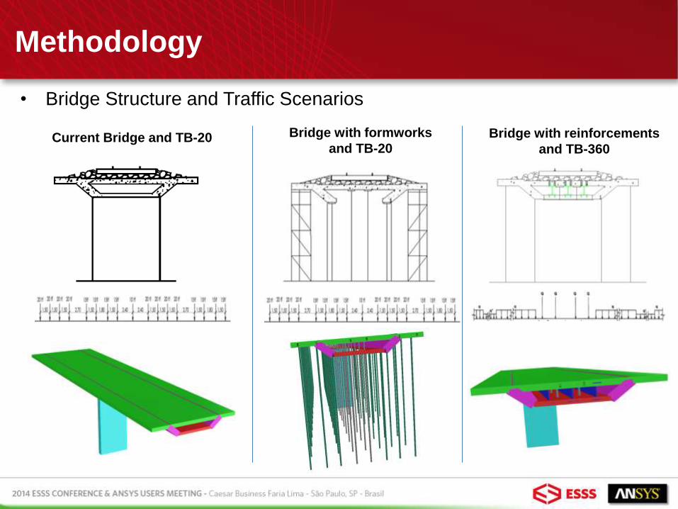
• Bridge Structure and Traffic Scenarios
Current Bridge and TB-20 Bridge with formworks
and TB-20 Bridge with reinforcements
and TB-360
Methodology
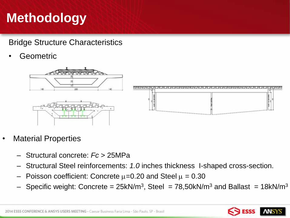
Bridge Structure Characteristics
• Geometric
• Material Properties
– Structural concrete: Fc > 25MPa
– Structural Steel reinforcements: 1.0 inches thickness I-shaped cross-section.
– Poisson coefficient: Concrete m=0.20 and Steel m = 0.30
– Specific weight: Concrete = 25kN/m3, Steel = 78,50kN/m3 and Ballast = 18kN/m3
Methodology
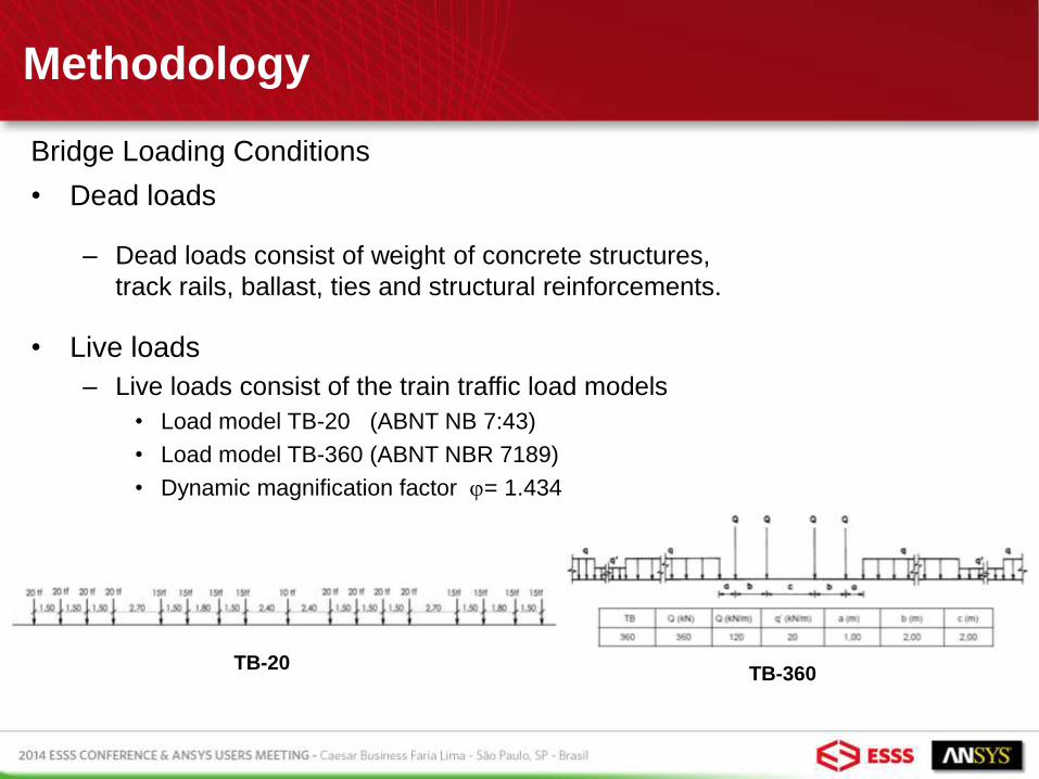
Bridge Loading Conditions
• Dead loads
– Dead loads consist of weight of concrete structures,
track rails, ballast, ties and structural reinforcements.
• Live loads
– Live loads consist of the train traffic load models
• Load model TB-20 (ABNT NB 7:43)
• Load model TB-360 (ABNT NBR 7189)
• Dynamic magnification factor = 1.434
TB-20 TB-360

Methodology
• Bridge Structure - Design Strength
– According standard NBR 6118 for Ultimate Limit States (ULS):
Methodology
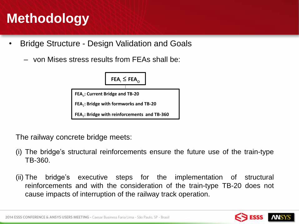
• Bridge Structure - Design Validation and Goals
– von Mises stress results from FEAs shall be:
FEAi ≤ FEAo
FEAo: Current Bridge and TB-20
FEA1: Bridge with formworks and TB-20
FEA2: Bridge with reinforcements and TB-360
The railway concrete bridge meets:
(i) The bridge’s structural reinforcements ensure the future use of the train-type
TB-360.
(ii) The bridge’s executive steps for the implementation of structural
reinforcements and with the consideration of the train-type TB-20 does not
cause impacts of interruption of the railway track operation.

Methodology
Finite Element Modeling
• Concrete structures and structural steel reinforcements modeled by ANSYS
SHELL181 element.
• Formwork structures modeled by ANSYS BEAM188 element.
• Track rails modeled by fictitious beam elements to apply the live loads (bridge
traffic loading).
• Boundary conditions: Soil-structure interaction represented by restriction all
translation for the bridge’s foundation and the basis of formwork structures.
• Dead loading applied as gravitational load and the weight of track rails
represented by beam pressure loads.
• Live loads (traffic load models: TB-20 and TB-360) simulated by concentrated
loads and beam pressure loads applied on the track rails.
• Materials linear elastic isotropic.

Methodology
Finite Element Models
Current Bridge and TB-20
Bridge with
formworks and TB-20

Methodology
Finite Element Models and Traffic Load Models
Traffic load models: TB-20 and TB-360
Bridge with reinforcements
and TB-360
Results
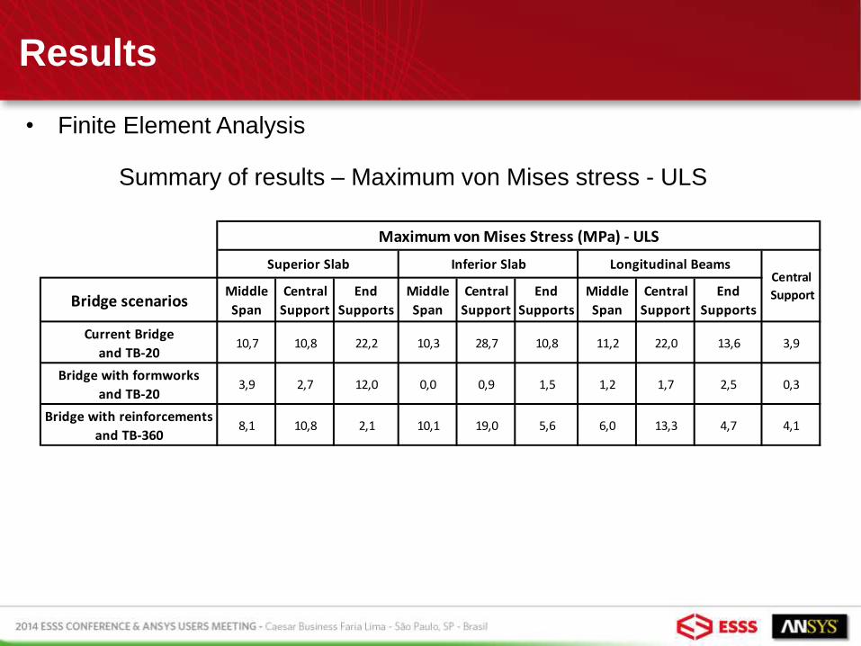
• Finite Element Analysis
Summary of results – Maximum von Mises stress - ULS
Bridge scenarios
Middle
Span
Central
Support
End
Supports
Middle
Span
Central
Support
End
Supports
Middle
Span
Central
Support
End
Supports
Current Bridge
and TB-2010,7 10,8 22,2 10,3 28,7 10,8 11,2 22,0 13,6 3,9
Bridge with formworks
and TB-203,9 2,7 12,0 0,0 0,9 1,5 1,2 1,7 2,5 0,3
Bridge with reinforcements
and TB-3608,1 10,8 2,1 10,1 19,0 5,6 6,0 13,3 4,7 4,1
Superior Slab Inferior Slab Longitudinal BeamsCentral
Support
Maximum von Mises Stress (MPa) - ULS
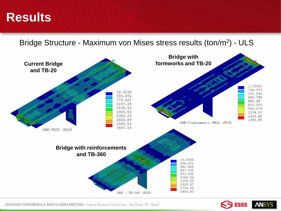
Bridge Structure - Maximum von Mises stress results (ton/m2) - ULS
Bridge with
formworks and TB-20
Bridge with reinforcements
and TB-360
Current Bridge
and TB-20
Results

Results
Superior and Inferior Slabs - Maximum von Mises stress results (ton/m2) - ULS
Current Bridge and TB-20 Bridge with
formworks and TB-20 Bridge with reinforcements
and TB-360
Results
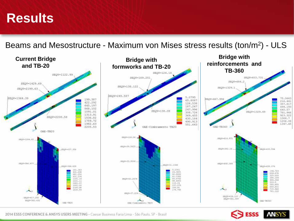
Beams and Mesostructure - Maximum von Mises stress results (ton/m2) - ULS
Current Bridge
and TB-20 Bridge with
formworks and TB-20
Bridge with
reinforcements and
TB-360

Results
Structural Reinforcements - Maximum von Mises stress results (ton/m2) - ULS Bridge with reinforcements and TB-360
WEBS
SUPERIOR
FLANGES INFERIOR
FLANGES

Results
Structural Reinforcements - Maximum Principal stress results (ton/m2) - ULS Bridge with reinforcements and TB-360
WEBS
SUPERIOR
FLANGES INFERIOR
FLANGES
Results
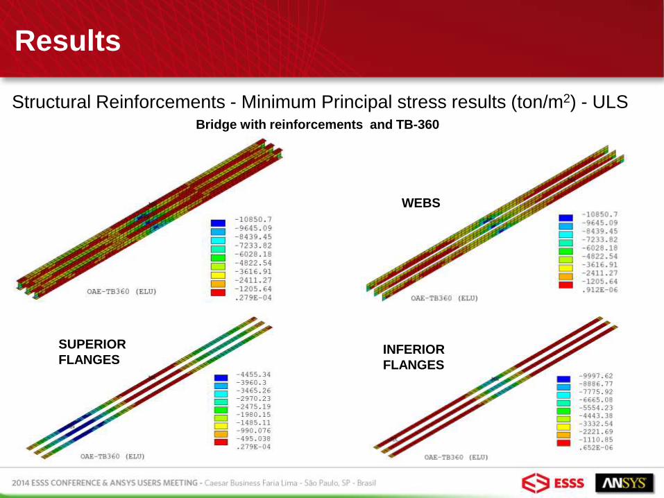
Structural Reinforcements - Minimum Principal stress results (ton/m2) - ULS Bridge with reinforcements and TB-360
WEBS
SUPERIOR
FLANGES INFERIOR
FLANGES
Results
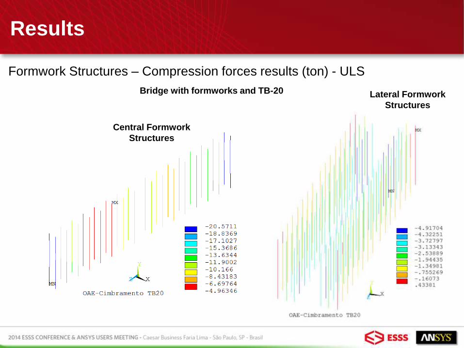
Formwork Structures – Compression forces results (ton) - ULS
Bridge with formworks and TB-20
Central Formwork
Structures
Lateral Formwork
Structures

Conclusion
By the results presented previously, it is noted that the values of von
Mises stress obtained for scenarios (2) and (3) are smaller than those
obtained from scenario (1).
Thus, it is concluded that the railway concrete bridge meets:
• The bridge’s structural reinforcements ensure the future use of the
train-type TB-360.
• The bridge’s executive steps for the implementation of structural
reinforcements and with the consideration of the train-type TB-20
does not cause impacts of interruption of the railway track operation.