Finite-difference frequency-domain modeling of ... · isotropic media with a tilted symmetry axis....
21
Finite-difference frequency-domain modeling of viscoacoustic wave propagation in 2D tilted transversely isotropic „TTI… media Stéphane Operto 1 , Jean Virieux 2 , A. Ribodetti 1 , and J. E. Anderson 3 ABSTRACT A 2D finite-difference, frequency-domain method was devel- oped for modeling viscoacoustic seismic waves in transversely isotropic media with a tilted symmetry axis. The medium is pa- rameterized by the P-wave velocity on the symmetry axis, the density, the attenuation factor, Thomsen’s anisotropic parame- ters and , and the tilt angle. The finite-difference discretiza- tion relies on a parsimonious mixed-grid approach that designs accurate yet spatially compact stencils. The system of linear equations resulting from discretizing the time-harmonic wave equation is solved with a parallel direct solver that computes monochromatic wavefields efficiently for many sources. Disper- sion analysis shows that four grid points per P-wavelength pro- vide sufficiently accurate solutions in homogeneous media. The absorbing boundary conditions are perfectly matched layers PMLs. The kinematic and dynamic accuracy of the method was assessed with several synthetic examples which illustrate the propagation of S-waves excited at the source or at seismic dis- continuities when . In frequency-domain modeling with absorbing boundary conditions, the unstable S-wave mode is not excited when , allowing stable simulations of the P-wave mode for such anisotropic media. Some S-wave instabilities are seen in the PMLs when the symmetry axis is tilted and . These instabilities are consistent with previous theoretical analyses of PMLs in anisotropic media; they are removed if the grid interval is matched to the P-wavelength that leads to disper- sive S-waves. Comparisons between seismograms computed with the frequency-domain acoustic TTI method and a finite- difference, time-domain method for the vertical transversely isotropic elastic equation show good agreement for weak to moderate anisotropy. This suggests the method can be used as a forward problem for viscoacoustic anisotropic full-waveform inversion. INTRODUCTION It is well acknowledged that accounting for anisotropy in depth seismic imaging can improve reservoir delineation in oil and gas ex- ploration. Anisotropic seismic imaging generally relies on the as- sumption of vertical transverse isotropy VTI, which can provide a good representation of intrinsic anisotropy of shales in sedimentary basins Tsvankin, 2001. More complex tectonic environments in- volving dipping structures such as foothills and overthrust areas need to account for a tilted symmetry axis in transversely isotropic TTI media Boudou et al., 2007; Charles et al., 2008. Deep crustal exploration using long-offset acquisition surveying is another con- text where anisotropy can significantly influence the seismic data as waves recorded by this acquisition design travel with a broad range of incidence angles Jones et al., 1999; Okaya and McEvelly, 2003. We present a 2D finite-difference, frequency-domain FDFD method to model seismic wave propagation in viscoacoustic trans- versely isotropic media with arbitrary tilted symmetry axis. Our mo- tivation behind this modeling method is to introduce anisotropy into the frequency-domain viscoacoustic full-waveform inversion FWI of wide-aperture seismic data. Over the last decade, frequency-domain FWI has been acknowl- edged as a promising approach to build high-resolution velocity models in complex environments Pratt and Shipp, 1999; Ravaut et al., 2004; Brenders and Pratt, 2007b. Frequency-domain FWI is based on the full two-way wave equation that needs to be solved for many sources at each inversion iteration. Therefore, a computa- tionally efficient modeling tool is a central ingredient for 2D and 3D FWIs that are tractable on distributed-memory platforms. Manuscript received by the Editor 20 October 2008; revised manuscript received 3 April 2009; published online 27 August 2009. 1 Université de Nice Sophia-Antipolis, GéosciencesAzur,Villefranche-sur-mer, France. E-mail: [email protected]; [email protected]. 2 Université Joseph Fourier, Laboratoire de Géophysique Interne etTectonophysique, Grenoble, France. E-mail: [email protected]. 3 ExxonMobil, Houston, Texas, U.S.A. E-mail: [email protected]. © 2009 Society of Exploration Geophysicists. All rights reserved. GEOPHYSICS, VOL. 74, NO. 5 SEPTEMBER-OCTOBER 2009; P. T75–T95, 16 FIGS., 3 TABLES. 10.1190/1.3157243 T75 Downloaded 17 Nov 2009 to 86.219.18.209. Redistribution subject to SEG license or copyright; see Terms of Use at http://segdl.org/
Transcript of Finite-difference frequency-domain modeling of ... · isotropic media with a tilted symmetry axis....

Fp
S
spsgbvn�etwo
©
GEOPHYSICS, VOL. 74, NO. 5 �SEPTEMBER-OCTOBER 2009�; P. T75–T95, 16 FIGS., 3 TABLES.10.1190/1.3157243
inite-difference frequency-domain modeling of viscoacoustic waveropagation in 2D tilted transversely isotropic „TTI… media
téphane Operto1, Jean Virieux2, A. Ribodetti1, and J. E. Anderson3
apcaemsTagswdimai
ABSTRACT
A 2D finite-difference, frequency-domain method was devel-oped for modeling viscoacoustic seismic waves in transverselyisotropic media with a tilted symmetry axis. The medium is pa-rameterized by the P-wave velocity on the symmetry axis, thedensity, the attenuation factor, Thomsen’s anisotropic parame-ters � and � , and the tilt angle. The finite-difference discretiza-tion relies on a parsimonious mixed-grid approach that designsaccurate yet spatially compact stencils. The system of linearequations resulting from discretizing the time-harmonic waveequation is solved with a parallel direct solver that computesmonochromatic wavefields efficiently for many sources. Disper-sion analysis shows that four grid points per P-wavelength pro-vide sufficiently accurate solutions in homogeneous media. Theabsorbing boundary conditions are perfectly matched layers�PMLs�. The kinematic and dynamic accuracy of the method was
mvtt�
emabftF
ceived 3-mer, Frophysiq
obil.co
T75
Downloaded 17 Nov 2009 to 86.219.18.209. Redistribution subject to
ssessed with several synthetic examples which illustrate theropagation of S-waves excited at the source or at seismic dis-ontinuities when � � � . In frequency-domain modeling withbsorbing boundary conditions, the unstable S-wave mode is notxcited when � � � , allowing stable simulations of the P-waveode for such anisotropic media. Some S-wave instabilities are
een in the PMLs when the symmetry axis is tilted and � � � .hese instabilities are consistent with previous theoreticalnalyses of PMLs in anisotropic media; they are removed if therid interval is matched to the P-wavelength that leads to disper-ive S-waves. Comparisons between seismograms computedith the frequency-domain acoustic TTI method and a finite-ifference, time-domain method for the vertical transverselysotropic elastic equation show good agreement for weak to
oderate anisotropy. This suggests the method can be used asforward problem for viscoacoustic anisotropic full-waveform
nversion.
INTRODUCTION
It is well acknowledged that accounting for anisotropy in deptheismic imaging can improve reservoir delineation in oil and gas ex-loration. Anisotropic seismic imaging generally relies on the as-umption of vertical transverse isotropy �VTI�, which can provide aood representation of intrinsic anisotropy of shales in sedimentaryasins �Tsvankin, 2001�. More complex tectonic environments in-olving dipping structures such as foothills and overthrust areaseed to account for a tilted symmetry axis in transversely isotropicTTI� media �Boudou et al., 2007; Charles et al., 2008�. Deep crustalxploration using long-offset acquisition surveying is another con-ext where anisotropy can significantly influence the seismic data asaves recorded by this acquisition design travel with a broad rangef incidence angles �Jones et al., 1999; Okaya and McEvelly, 2003�.
Manuscript received by the Editor 20 October 2008; revised manuscript re1Université de Nice Sophia-Antipolis, GéosciencesAzur, Villefranche-sur2Université Joseph Fourier, Laboratoire de Géophysique Interne et Tecton3ExxonMobil, Houston, Texas, U.S.A. E-mail: john.e.anderson1@exxonm2009 Society of Exploration Geophysicists.All rights reserved.
We present a 2D finite-difference, frequency-domain �FDFD�ethod to model seismic wave propagation in viscoacoustic trans-
ersely isotropic media with arbitrary tilted symmetry axis. Our mo-ivation behind this modeling method is to introduce anisotropy intohe frequency-domain viscoacoustic full-waveform inversionFWI� of wide-aperture seismic data.
Over the last decade, frequency-domain FWI has been acknowl-dged as a promising approach to build high-resolution velocityodels in complex environments �Pratt and Shipp, 1999; Ravaut et
l., 2004; Brenders and Pratt, 2007b�. Frequency-domain FWI isased on the full �two-way� wave equation that needs to be solvedor many sources at each inversion iteration. Therefore, a computa-ionally efficient modeling tool is a central ingredient for 2D and 3DWIs that are tractable on distributed-memory platforms.
April 2009; published online 27August 2009.ance. E-mail: [email protected]; [email protected], Grenoble, France. E-mail: [email protected].
SEG license or copyright; see Terms of Use at http://segdl.org/

cfdbwlficrpsNcpio2
mmqHaiffu
edAptapamTdettett
AsdizdmSmew
smi�
glthSscae�
Patwgbs
ngeoc
tmtTr2ebmantdt�Ed
Ztwatmos
T76 Operto et al.
Multiscale frequency-domain FWI generally is performed by suc-essive inversions of a limited subset of frequencies, proceedingrom low frequencies to higher ones �Sirgue and Pratt, 2004; Bren-ers and Pratt, 2007a�. In two dimensions, these few frequencies cane modeled efficiently in the frequency domain. Frequency-domainave modeling reduces to the resolution of a large, sparse system of
inear equations, the solution for which is a monochromatic wave-eld with the right-hand-side term as the source. The most efficientomputational approach to solve this system for a large number ofight-hand-side terms is to perform one LU factorization of the im-edance matrix with a direct solver, followed by forward/backwardubstitutions for each right-hand-side term �see Marfurt �1984� andihei and Li �2007� for a comparison between time and memory
omplexities of time-domain and frequency-domain modeling ap-roaches�. Parallel frequency-domain modeling is performed by us-ng a massively parallel direct solver that reduces the computing costf the factorization by over an order of magnitude �Operto et al.,007b; Sourbier et al., 2009a, 2009b�.
Compact mixed-grid, finite-difference stencils with antilumpedass have been developed specifically for 2D and 3D frequency-do-ain modeling based on a direct solver to minimize the memory re-
uirement of LU factorization �Jo et al., 1996; Stekl and Pratt, 1998;ustedt et al., 2004; Operto et al., 2007b�. Massively parallel FWI
lgorithms based on this forward-modeling approach are presentedn Sourbier et al. �2009a, 2009b� and Ben Hadj Ali et al. �2008�. Therequency domain also allows the implementation of attenuation ef-ects of arbitrary complexity without extra computational effort bysing complex velocities �Toksöz and Johnston, 1981�.
We extend the viscoacoustic isotropic modeling method of Hust-dt et al. �2004� to a viscoacoustic TTI wave equation. A fourth-or-er acoustic wave equation for VTI media was originated bylkhalifah �2000�. The wave equation is derived from the exact ex-ression of the phase velocity within which the S-wave velocity onhe symmetry axis is set to zero. Alkhalifah �2000� shows that hiscoustic VTI wave equation is accurate kinematically for P-waveropagation. Zhang et al. �2005� extend his equation to considercoustic TTI media. They illustrate the effects of the tilt of the sym-etry axis on the kinematics of the arrivals by comparing VTI andTI seismograms with an explicit high-order, finite-difference time-omain �FDTD� method. Zhou et al. �2006� extend Alkhalifah’squation to the TTI case and recast the resulting fourth-order equa-ion into a coupled system of second-order partial differential equa-ions; these are more suitable for numerical implementation and areasier to interpret from a physical viewpoint. This system of equa-ions is implemented with a classic FDTD method, and some simula-ions in homogeneous media are presented.
Several limitations of the acoustic anisotropic wave equation oflkhalifah �2000� can be identified. His wave equation does not de-
cribe any physically realizable phenomenon because acoustic me-ia intrinsically are isotropic. Rather, Alkhalifah’s �2000� equations derived by setting the S-wave velocity on the symmetry axis VS0
toero in the expression of the phase velocity for VTI media. This con-ition does not prevent the propagation of S-waves out of the sym-etry axis �Grechka et al., 2004; Zhang et al., 2005�, and these-waves must be regarded as artifacts in the framework of acousticodeling. The fact that shear waves are propagated means that his
quation cannot be considered as acoustic in the strict sense of theord.
Downloaded 17 Nov 2009 to 86.219.18.209. Redistribution subject to
During numerical modeling, S-waves are excited at seismicources located in a VTI or TTI layer or can be converted from the P-ode at interfaces. These shear waves are not excited in elliptical an-
sotropic media. Furthermore, acoustic VTI media characterized by� � do not satisfy the stability condition for hexagonal symmetry
iven by C33C11�C132 � 0 when � � � and Cij are the elastic modu-
i �Helbig, 1994; p. 191�. The analytical solutions of the VTI equa-ion show that one mode is unstable when � � � �Alkhalifah, 2000;is equations 20–21 and his Figure 1�; the phase velocity of the-wave mode, which becomes imaginary when � � � , stronglyuggests that the unstable mode is the undesired S-wave mode �Gre-hka et al., 2004; their equations 1 and 5�. Therefore, time-domainnisotropic acoustic modeling based on the full solution of the wavequation has been limited to acoustic VTI media characterized by �
� .Of note, the undesired S-wavefield can be separated from the
-wavefield in the phase-shift extrapolation method because the P-nd S-wave solutions lie in a different part of the wavenumber spec-rum �Bale, 2007�. The unstable S-wave mode can be cancelled outhen � � � by choosing the sign of the phase-shift operator thatuarantees evanescent decay of the S-waves. Thus, numerically sta-le simulation of the P-wavefield can be performed with a phase-hift extrapolation method when � � � �Bale, 2007�.
Whereas the acoustic anisotropic wave equation is sufficiently ki-ematically accurate to perform prestack depth and reverse-time mi-ration in anisotropic media �see Duveneck et al. �2008� for a recentxample�, amplitude modeling appears to be inaccurate, although tour knowledge no numerical studies quantify this level of inaccura-y.
In this paper, we implement the equation of Zhou et al. �2006� inhe frequency domain rather than in the time domain for efficient
ultisource modeling of monochromatic wavefields. In a first at-empt to incorporate anisotropy in FWI, we consider a viscoacousticTI wave equation rather than an elastic one with more general rep-
esentation of anisotropy �Carcione et al., 1992; Komatitsch et al.,000; Saenger and Bohlen, 2004�. The first obvious reason is thatlastic modeling is more demanding than acoustic, among others,ecause the elastic wave equation is discretized according to theinimum S-wavelength, leading to a finer grid interval than in the
coustic case. The second motivation is to deal with a more limitedumber of parameter classes in FWI to manage the ill-posedness ofhe inverse problem. In this paper, the viscoacoustic anisotropic me-ium is parameterized by the P-wave velocity on the symmetry axis,he density, the attenuation factor, the anisotropic parameters � and, and the tilt angle, which is not supposed constant in the medium.lliptic anisotropy can be considered easily by setting � �� , furtherecreasing the number of independent parameters if necessary.
In the next section, we review the TTI acoustic wave equation ofhou et al. �2006� and extend it to incorporate heterogeneous densi-
y. Following that, we discretize the TTI acoustic wave equationith the FDFD method. Perfectly matched layers �PMLs� are used
s absorbing boundary conditions �Berenger, 1994�. Some instabili-ies of the PMLs in the TTI case are highlighted. The source imple-
entation is then discussed to find a way to attenuate the excitationf the S-waves. In the fourth section, we present a dispersion analy-is in homogeneous media, which shows that four grid points per
SEG license or copyright; see Terms of Use at http://segdl.org/

Pniwct
Z
w
wdAtvasect
ctttott�
i
i
w
A
C
C
E
G
a
cse
1a2
2D acoustic wave modeling in TTI media T77
-wavelength provide sufficiently accurate simulations in homoge-ous media. In the fifth section, the numerical simulations providensight into the kinematic and dynamic accuracy of the acoustic TTIave equation in comparison with the elastic wave equation. We
onclude with a discussion of the reliability of the anisotropic acous-ic wave equation for performing anisotropic FWI.
THE TTI ACOUSTIC WAVE EQUATION
We start from a modification of the 2D acoustic wave equation ofhou et al. �2006� for TTI anisotropic media:
�1
�0
� 2p
� t2 � �1�2� �Hp�H0p� �1�2� �Hq
1
�0
� 2q
� t2 �2�� �� �Hq�2�� �� �Hp �, �1�
ith
H�cos2 � 0�
�xb
�
�x�sin2 � 0
�
� zb
�
� z
�sin 2� 0
2� �
�xb
�
� z�
�
� zb
�
�x�,
H0�sin2 � 0�
�xb
�
�x�cos2 � 0
�
� zb
�
� z
�sin 2� 0
2� �
�xb
�
� z�
�
� zb
�
�x�, �2�
here p is the pressure wavefield, q is an auxiliary wavefield intro-uced by Zhou et al. �2006� to recast the fourth-order equation oflkhalifah �1998� into the system of second-order equations 1, �0 is
he bulk modulus along the symmetry axis, and b is buoyancy, the in-erse of density. The values � and � are Thomsen’s dimensionlessnisotropic parameters �Thomsen, 1986�, and � 0 is the angle of theymmetry axis with respect to the z-axis. Compared to the originalquation of Zhou et al. �2006�, we introduce heterogeneous buoyan-y in operators H and H0, taking advantage of the analogy of equa-ions 1 and 2 with the isotropic wave equation.
The second equation in the system of equation 1 vanishes in thease of elliptical anisotropy �� �� �. If � �� �� �0, then equa-ion 1 reduces to the second-order acoustic isotropic wave equation,he solution of which is the pressure wavefield. Also of note is thathe tilt of the anisotropy introduces some cross-derivative terms inperators H and H0. The source term of the first expression of equa-ion 1 depends on the q-wavefield, the amplitude of which is con-rolled by the amount of anellipticity, as revealed by the coefficient� �� � in the source term of the second expression of equation 1.
We can transform the previous system of second-order equationsnto a hyperbolic system of first-order equations by introducing aux-
Downloaded 17 Nov 2009 to 86.219.18.209. Redistribution subject to
liary wavefields px, pz, qx, and qz:
⎩⎪⎨⎪⎧
1
�0
� p
� t� Ax
� px
�x�Bx
� pz
�x�Cx
�qx
�x�Dx
�qz
�x
�Az� px
� z�Bz
� pz
� z�Cz
�qx
� z�Dz
�qz
� z
1
�0
�q
� t� Ex
� px
�x�Fx
� pz
�x�Gx
�qx
�x�Hx
�qz
�x
�Ez� px
� z�Fz
� pz
� z�Gz
�qx
� z�Hz
�qz
� z
� px
� t� b
� p
�x
� pz
� t� b
� p
� z
�qx
� t� b
�q
�x
�qz
� t� b
�q
� z ⎭⎪⎬⎪⎫
,
�3�
here the coefficients
x�1�2� cos2�� �, Bx��� sin�2� �,
x� �1�2� �cos2�� �, Dx���1�2� �sin�2� �
2,
Az�Bx, Bz�1�2� sin2�� �,
z�Dx, Dz� �1�2� �sin2�� �,
x�2�� �� �cos2�� �, Fx���� �� �sin�2� �,
x�Ex, Hx�Fx,
nd
Ez�Fx,Fz�2�� �� �sin2�� �, Gz�Fx,Hz�Fz �4�
an be introduced for compactness. By analogy with the velocity-tress formulation of the isotropic acoustic wave equation �Hustedtt al., 2004�, px, pz, qx, and qz represent particle velocity wavefields.
We take the Fourier transform with respect to time and introduceD damping functions � x�x� and � z�z� for convolutional �C� PMLbsorbing boundary conditions, e.g. �Drossaert and Giannopoulos,007; Komatitsch and Martin, 2007�,
SEG license or copyright; see Terms of Use at http://segdl.org/

Twaapm
iw�aa
PP
ecalec1acmi
stsl
utplgibteww
A
fia41Cts
iodcOvcbq
sf
wBtrsmitretut
T78 Operto et al.
⎩⎪⎨⎪⎧
�i�
�0p �
1
� x�Ax
� px
�x�Bx
� pz
�x�Cx
�qx
�x�Dx
�qz
�x�
�1
� z�Az
� px
� z�Bz
� pz
� z�Cz
�qx
� z�Dz
�qz
� z�
�i�
�0q �
1
� x�Ex
� px
�x�Fx
� pz
�x�Gx
�qx
�x�Hx
�qz
�x�
�1
� z�Ez
� px
� z�Fz
� pz
� z�Gz
�qx
� z�Hz
�qz
� z�
�i�px �b
� x
� p
�x
�i�pz �b
� z
� p
� z
�i�qx �b
� x
�q
�x
�i�qz �b
� z
�q
� z ⎭⎪⎬⎪⎫
.
�5�he C-PML function � x has the form � x� x� �dx / �x� i���,here dx, x, and x are damping functions, discussed in Komatitsch
nd Martin �2007� and Drossaert and Giannopoulos �2007�. Attenu-tion effects, including frequency-dependent attenuation, can be im-lemented easily in equation 5 by making the velocity on the sym-etry axis complex �Toksöz and Johnston, 1981�.
FDFD DISCRETIZATION
We have discretized equation 5 using the mixed-grid method orig-nally introduced by Jo et al. �1996� and have recast it in the frame-ork of the parsimonious staggered-grid method of Hustedt et al.
2004�. The parsimonious mixed-grid method is applied to the 2Dnd 3D isotropic acoustic wave equations by Hustedt et al. �2004�nd Operto et al. �2007b�, respectively.
arsimonious mixed-grid finite-difference method:rinciple
Spatial derivatives in the second-order wave equation �such asquation 1� are discretized using O��x2� stencils on different rotatedoordinate systems �in two dimensions, the Cartesian axes x and znd the 45° rotated axes�. The resulting stencils are combined linear-y to derive numerically isotropic stencils. This trick is complement-d by a mass-term distribution �an antilumped mass� that signifi-antly improves the accuracy of the mixed-grid stencil �Marfurt,984�. The linear combination of the stencils of low-order accuracynd the mass distribution allow us to design accurate and spatiallyompact stencils. This latter feature is crucial to minimize the nu-erical bandwidth of the impedance matrix and hence its filling dur-
ng LU factorization.The O��x2� stencils of the second-order wave equation are de-
igned using a parsimonious staggered-grid method developed forhe time-domain wave equation �Luo and Schuster, 1990�. In the par-imonious approach, the wave equation is written as a first-order ve-ocity-stress hyperbolic system �such as equation 5� and discretized
Downloaded 17 Nov 2009 to 86.219.18.209. Redistribution subject to
sing O��x2� staggered-grid stencils in the different coordinate sys-ems �Virieux, 1984; Saenger et al., 2000�. After discretization, thearticle velocities �in the acoustic case� are eliminated from the ve-ocity-stress wave equation, leading to a parsimonious staggered-rid wave equation on each coordinate system, the solution of whichs the pressure wavefield. Once discretization and elimination haveeen applied in each coordinate system, the resulting discrete opera-ors are combined linearly to end up with a single discrete wavequation. A necessary condition for this combination is that theavefields kept after elimination are discretized in the same grid,hatever the coordinate system selected.
pplication to 2D TTI acoustic wave equation
We have applied this discretization strategy to equation 5. Therst-order partial derivatives in equation 5 are discretized along thexis of the two coordinate systems �the classic Cartesian one and the5° rotated one� using O��x2� staggered-grid stencils �Virieux,986; Saenger et al., 2000�. The resulting stencils are referred to asartesian system �CS� and rotated system �RS�.After discretization,
he auxiliary wavefields px, pz, qx, and qz are eliminated from theystem to end up with a system of two second-order equations in
p and q.The geometry of the staggered grids for the CS and RS stencils is
llustrated in Figure 1. The TTI equation is inconsistent with the ge-metry of the CS stencil. Indeed, the p- and q-wavefields need to beefined at the four corners and in the middle of the cell because of theross-derivatives in H and H0 �Figure 1b�. Because we used the��x2� stencil, we performed bilinear interpolation to estimate the
alue of p and q in the middle of the cell from their values at the fourorners. In contrast, no interpolation is required for the RS stencilecause the p- and q-wavefields and the auxiliary wavefields px, pz,
x, and qz are defined in the same grid �Figure 1a�.After discretization and linear combination of the two stencils, the
ystem of second-order wave equations can be written in matrixorm as
�Mp�w1Ar� �1�w1�Ac w1Br� �1�w1�Bc
w1Cr� �1�w1�Cc Mq�w1Dr� �1�w1�Dc�
��p
q���0
0�, �6�
here Mp denotes the diagonal mass matrix of coefficients �2 /�0.locks Ar, Br, Cr, Dr and Ac, Bc, Cc, Dc form the stiffness matrices for
he RS and CS stencils, respectively. The coefficient w1 controls theespective weight of the two stencils; it is determined during disper-ion analysis by minimizing the phase-velocity dispersion. Theixed-grid stencil contains nine coefficients spanning over two grid
ntervals �Figure 2; Appendices A and B�. This implies that each ofhe four �nx�nz�2 blocks of the matrix in equation 6 has nine nonze-o coefficients per row. The symmetric band-diagonal pattern ofach submatrix is the same as that shown by Hustedt et al. �2004� forhe isotropic acoustic wave equation �Hustedt et al., 2004; their Fig-re 10a�. In the case of elliptic anisotropy, the q-wavefield is nil;herefore, only the upper-left block remains in equation 8.
SEG license or copyright; see Terms of Use at http://segdl.org/

pd
A
p
a�
wm
cds
e
H
F�tTf
b
v
FgTpeail
2D acoustic wave modeling in TTI media T79
The coefficients of submatrices Ar, Br, Cr, and Dr are given in Ap-endix A; those of submatrices Ac, Bc, Cc, and Dc are given inAppen-ix B.
ntilumped mass
One can also introduce a mass term averaging over the nine gridoints of the mixed-grid stencil to improve stencil accuracy. The di-
( i , j ) ( i + 1 , j )( i – 1 , j )
( i + 1 , j – 1 )( i , j – 1 )( i – 1 , j – 1 )
a)
b)
: p, q
: px , pz , qx , qz , b
x ′
x
z
x
z
( i – 1 , j + 1 ) ( i , j + 1 ) ( i + 1 , j + 1 )
z ′
( i + 1 , j – 1 )( i , j – 1 )( i – 1 , j – 1 )
( i , j ) ( i + 1 , j )( i – 1 , j )
( i – 1 , j + 1 ) ( i , j + 1 ) ( i + 1 , j + 1 )
:
: px , pz , qx , qz , b
: p, q, δ, , θ
p, q, δ, , θ
∋
∋
igure 1. Staggered-grid geometries. �a� RS staggered-grid stencils.b� CS staggered-grid stencils. The CS stencil requires estimatinghe p- and q-wavefields in the middle of the cell �dash squares�.hese are estimated by bilinear interpolation using the values at the
our nodes of the cell.
Downloaded 17 Nov 2009 to 86.219.18.209. Redistribution subject to
gonal term of the mass matrices is replaced by its weight averageStekl and Pratt, 1998�:
�2
� ij→wm1
�2
� ij�
wm2
4� �2
� i�1,j�
�2
� i�1,j�
�2
� i,j�1�
�2
� i,j�1�
��1�wm1�wm2�
4� �2
� i�1,j�1�
�2
� i�1,j�1
��2
� i�1,j�1�
�2
� i�1,j�1�, �7�
here we introduce two new mass coefficients wm1 and wm2, deter-ined jointly with w1 during the dispersion analysis.
DISPERSION ANALYSIS
To assess the accuracy of the mixed-grid stencil, we perform alassical harmonic dispersion analysis for infinite homogeneous me-ia. This dispersion analysis is applied to the RS, CS, and mixed-gridtencils.
We insert the following discrete plane wave in the discrete wavequation for a homogeneous medium:
�p
q���P
Q�eikh�m cos �n sin � �8�
ere, k�� /cP0is the wavenumber, h is the grid interval, is the in-
a)
)0 0.05 0.10 0.15 0.20 0.25
0.985
0.990
0.995
1.000
0 0.05 0.10 0.15 0.20 0.250.985
0.990
0.995
1.000
1/G
∼Pvph
-0.2 -0.1 0.0 0.1 0.2-0.2
-0.1
0.0
0.1
0.2
Relative error in x-direction (%)
Rela
tive
erro
rin
z-d
irec
tio
n(%
)
∼phS
igure 2. Normalized phase velocity as a function of the number ofrid points per wavelength for the �a� P-wave and �b� S-wave modes.he dispersion curves are computed with the mixed-grid stencil forropagation angles of 0°, 15°, 30°, 45°, 60°, and 75° and for Thoms-n’s parameters � �0.1 and � �0.25. The inset in �a� shows the rel-tive error in percentages of the P-wave phase velocity for G�5,.e., � vphase
P �1��100 �see text for details�. The maximum error isess than 0.2%.
SEG license or copyright; see Terms of Use at http://segdl.org/

cs
wig
bct
wt
vmttjabie
tmstSi
Tt
wtia
fo�uao�
m�tcm
trmaptmcSas
aaZ
caa
Fo��
Tm
w
0
T80 Operto et al.
idence angle of the plane wave, x�mh, and z�nh. This leads to aystem of equations in P and Q of the form
���2
cP0
2 0
0�2
cP0
2 ��� kG
2��2�a11 a12
a21 a22�
M��P
Q���0
0�,
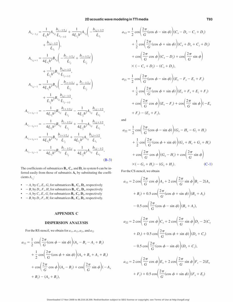
�9�here the expression of the coefficients a11, a12, a21, and a22 are given
n Appendix C for the RS and CS stencils; G denotes the number ofrid points per wavelength, G�2� /kh.
The two eigenvalues e���2 /cP0
2 of the matrix M are providedy the roots of the characteristic polynomial det�M�eI��0. Wean infer from their expressions the numerical phase velocities of thewo modes:
vphP ��� cP0
G
2��
����a11�a22
2���a11�a22�2
4�a11a22�a12a21,
vphS ��� cP0
G
2��
����a11�a22
2���a11�a22�2
4�a11a22�a12a21,
�10�
here vphP corresponds to the P-wave mode and vph
S corresponds tohe S-wave mode.
For � � � , the term beneath the outer square root is negative for
phS , which implies that the S-wave will grow exponentially duringodeling, leading to numerical instabilities. This is consistent with
he analytical plane-wave analysis of the VTI acoustic wave equa-ion of Alkhalifah �2000�, which shows that one set of complex-con-ugate solutions is unstable when � � � �Alkhalifah, 2000; solution2 in his Figure 1�. The instability of the S-wave mode is also showny the expression of the S-wave phase velocity, which becomesmaginary when � � � and VS0
�0 �Grechka et al., 2004; theirquations 1 and 5�.
In spite of the intrinsic instability of the S-wave mode, we see laterhat we can perform stable numerical simulations of the P-wave
ode when � � � using our frequency-domain method. In fact, wehow that no S-waves are excited during frequency-domain simula-ion when � � � . We suggest that the excitation of the unstable-wave mode is cancelled out by the absorbing boundary conditions
mplemented in the frequency-domain boundary value problem.
able 1. Optimal weighting coefficients for the anisotropicixed-grid stencil.
m1 wm2 w1
.6291844 0.3708126 0.4258673
Downloaded 17 Nov 2009 to 86.219.18.209. Redistribution subject to
We apply the same dispersion analysis to the mixed-grid stencil.o estimate the weighting coefficients w1, wm1, and wm3, we define
he following cost function:
C�w1,wm1,wm2��
G
�
�
�f�G, ,� ,� ,� ��2, �11�
ith the function f defined as f�G, ,� ,� ,� ��1� vphP . Here, vph
P ishe numerical phase velocity normalized by the exact P-wave veloc-ty for VTI media. The exact P- and S-wave velocities for VTI mediare given in Tsvankin �2001; his equation 1.55�.
We minimize the cost function by considering simultaneouslyour values of G �0.1, 0.15, 0.2, and 0.25�, four representative valuesf the �� ,� � pairs taken from Thomsen �1986� ��0.148 0.091�,�0.012 0.137�, �0.057 0.081�, and �0.1 0.225��, � �0, and six val-es of ranging from 0° to 75°. The cost function is minimized withvery fast simulated annealing algorithm �Sen and Stoffa, 1995�. Webtain the coefficients wm1�0.6291844, wm2�0.3708126, and w1
0.4258673 for a final rms of 1.4947164E-04 �Table 1�.The normalized phase-velocity dispersion curves for the twoodes are shown in Figure 2 for ranging from 0° to 75° and for �0.1 and � �0.2. These curves can be compared with those ob-
ained with the RS and CS stencils, respectively, to determine the ac-uracy improvement provided by the mixed-grid and antilumpedass strategies �see Operto et al., 2007a; their Figure 2a and b�.The dispersion curves for the P-mode shown in Figure 2a suggest
hat four grid points per wavelengths will provide sufficiently accu-ate simulations of P-waves in homogeneous media. Indeed, theaximum phase-velocity error is 0.4% for G�4, whereas the aver-
ge error is on the order of 0.1% the value of I �Figure 2a�. Thehase-velocity dispersion curves of the second mode normalized byhe exact phase velocity of the SV-wave confirm that the second
ode of the TTI acoustic equation corresponds to an S-wave. Thisurve is not shown for �0 because the phase velocity of the-wave is nil on the symmetry axis, through construction of thecoustic equation of Alkhalifah �2000�. We verified during disper-ion analysis that this velocity remains nil after discretization.
SOURCE EXCITATION
It is well acknowledged that applying a pressure source in thecoustic VTI/TTI equation leads to exciting an S-wave with a char-cteristic diamond shape �Alkhalifah, 2000; Grechka et al., 2004;hang et al., 2005�.Anderson et al. �2008� propose to modify the pressure source to
ancel the shear strains and therefore the excitation of the S-waves incoustic anisotropic media. The moment tensor source equivalent topressure source can be written as
dM11
dt��s1P,
dM33
dt��s3P . �12�
or an isotropic source, the weighting coefficientss1 and s3 equalne. In anisotropic acoustic media, we use s1�2��C11�C13� /C11�C13�C13�C33�� and s3�2��C13�C33� / �C11�C13�C13
C ��, where the C coefficients denote the elastic moduli.
33 ijSEG license or copyright; see Terms of Use at http://segdl.org/

eta
Nsint
�4aRwp�t
�
�uSstBsw
rslosm
tpTspwwlf�
ga
atSa
oitibatlwwb
cntoPirvsts
t2F
S
t
S
12atRcs
2D acoustic wave modeling in TTI media T81
We first apply the isotropic and anisotropic moment tensor sourc-s to the 2D VTI elastodynamic system for which the S-wave veloci-y on the symmetry axis is set to zero �this gives C44�0� to mimiccoustic propagation �Anderson et al., 2008�:
��vx
� t�b
�� xx
�x
�vz
� t�b
�� zz
� z
�� xx
� t�C11
�vx
�x�C13
�vz
� z
�� zz
� t�C13
�vx
�x�C33
�vz
� z
� . �13�
ote that equation 13 is not equivalent to the acoustic equation con-idered in our study. The anisotropic moment tensor source can bemplemented in equation 13 by incrementing at each time step theormal stresses � xx and � zz by �s1P and �s3P, respectively �Cou-ant et al., 1995�.
We discretize equation 13 in the time domain using the RS stencilSaenger et al., 2000�. The source wavelet is a Ricker wavelet with a-Hz dominant frequency. The P-wave velocity on the symmetryxis is 2 km /s, � �0.1, and � �0.2. The grid interval is 10 m. TheS stencil requires that the spatial distribution of the point sourceith a 2D Gaussian function is spread to guarantee an effective cou-ling between the stress and the particle velocity staggered gridsHustedt et al., 2004�. Here, we use horizontal and vertical correla-ion lengths of 40 m.
Snapshots for the isotropic �s1�s3�1� and anisotropic �s1
2��C11�C13� / �C11�C13�C13�C33�� and s3�2��C13�C33� /C11�C13�C13�C33�� moment tensor sources are shown in Fig-re 3a and b. Use of the anisotropic source helps to attenuate the-wave efficiently. However, the spatial smoothing of the pointource is a second feature required to attenuate the S-wave. Indeed,he S-wave has a higher wavenumber content than the P-wave �seeale, 2007; his Figure 1a�. Therefore, a spatial smoothing of the
ource can be found such that it partially low-pass filters the S-waveithout affecting the P-wavefront.We also performed a simulation with the CS stencil that does not
equire smoothing the source �Hustedt et al., 2004�. Withoutmoothing the point source, the attenuation of the S-wave was muchess efficient than in Figure 3b. This is not a result of the stencil ge-metry because we verified that the CS and the RS stencils led to theame S-wave attenuation when the source was smoothed in the sameanner.In a second step, we applied the isotropic and anisotropic moment
ensor sources to the acoustic VTI equation, recast as a first-order hy-erbolic system �equation 3� in the time domain �Figure 3c and d�.he RS stencil was used to discretize equation 3. The pressureource was implemented with horizontal and vertical dipoles ap-lied to the third and fourth equations of expression 3. Each dipoleas weighted by coefficients s1 and s2. The source was smoothedith a 2D Gaussian function; horizontal and vertical correlation
engths were 40 m. Although the S-wave was weakened, it was notully canceled when the anisotropic moment tensor source was usedFigure 3d�. To remove the S-wave efficiently, a correlation length as
Downloaded 17 Nov 2009 to 86.219.18.209. Redistribution subject to
reat as 80 m must be used, which leads to significant attenuationnd distortion of the P-wavefront �Figure 3e and f�.
So far, we have failed to remove the S-wave excitation efficientlyt the source in the case of the acoustic anisotropic equation whenhe source is located in a medium with � � � . To avoid exciting the-wave, the source can be set in an isotropic layer or in an ellipticallynisotropic layer.
PML ABSORBING BOUNDARY CONDITION
PML absorbing boundary conditions provided a good absorptionf the waves on the edges of the model. However, we have observednstabilities in the PML layers in the TTI case �i.e., when the symme-ry axis is tilted with respect to the vertical and horizontal PML-PMLnterfaces�. These instabilities, which are seen only when the num-er of grid points per wavelength is significantly greater than fournd when � � � , are likely caused by the S-waves. When the grid in-erval is set according to the rule of four grid points per P-wave-ength, the S-waves are affected strongly by numerical dispersion,hich may cancel out the instability �Hu, 2001�. When � � � , no S-aves are excited during frequency-domain modeling and no insta-ility is seen, whatever the discretization.
The instability of PMLs in anisotropic media is studied theoreti-ally by Bécache et al. �2003�. They show in their Figure 13 that aecessary condition to guarantee the stability of PMLs is that, alonghe velocity curves, the slowness vector and the group velocity areriented in the same way with respect to the Cartesian axis �i.e., theML-PML interfaces�. We plot the velocity curves for the S-waves
n a homogeneous medium for a vertical symmetry axis and for a 45°otated axes �Figure 4�. When the symmetry axis is tilted, the groupelocity vector and the slowness vector do not satisfy the geometrictability criterion of Bécache et al. �2003� �Figure 4b�, contrary tohe case where the symmetry axis is vertical �Figure 4a�. Furthertudy is required to remove this instability.
NUMERICAL EXAMPLES
In this section, we validate our method against analytical solu-ions along the symmetry axis and numerical solutions computed inD VTI elastic media with a classic staggered-grid velocity-stressDTD method.
imulation in homogeneous media
We first validate the method against an analytical solution alonghe symmetry axis available for class IV TI media �Payton, 1983�.
trong anisotropy: Zinc crystal
For the simulation, we consider a zinc crystal �Carcione et al.,988; Komatitsch et al., 2000�; properties are summarized in Table. The model measures 3300�3300 m with grid intervals for thecoustic FDFD and elastic FDTD simulations of 15 and 5 m, respec-ively. The source is in the middle of the grid. The source wavelet is aicker wavelt with a dominant frequency of 17 Hz. A horizontal re-eiver line is located above the source at a distance of 1 km. Theymmetry axis is vertical.
SEG license or copyright; see Terms of Use at http://segdl.org/

mfanlscmsot
FGiaga
�
scd
a
c
e
T82 Operto et al.
Snapshots computed with the acoustic FDFD and elastic FDTDethods are shown in Figure 5. The analytical velocity and wave-
ront contours for the quasilongitudinal and quasitransverse modesre superimposed in both snapshots �Carcione et al., 1988�. Good ki-ematic agreement is obtained between the analytical P- and S-ve-ocity curves and the VTI elastic wavefronts �Figure 5b�, whereasome mismatch is seen between the qP-wave analytical velocityurve and the VTI acoustic wavefront for directions of propagationidway between the symmetry axis and its perpendicular. Compari-
ons between the two snapshots of Figure 5 also suggest stronglyverestimated amplitudes in the acoustic solution perpendicular tohe symmetry axis.
–4
–3
–2
–1
0
1
2
3
4
–4 –3 –2 –1 0 1 2 3 4
–4
–3
–2
–1
0
1
2
3
4
–4 –3 –2 –1 0 1 2 3 4
Dep
th(k
m)
-4
-3
-2
-1
0
1
2
3
4
–4 –3 –2 –1 0 1 2 3 4
-4
-3
-2
-1
0
1
2
3
4
–4 –3 –2 –1 0
Dep
th(k
m)
Distance (km)
Dep
th(k
m)
–4
–3
–2
–1
0
1
2
3
4
–4 –3 –2 –1 0
0
1
2
3
4
–4
–3
–2
–1
–3 –2 –1
Distan) b)
) d)
) f)
Downloaded 17 Nov 2009 to 86.219.18.209. Redistribution subject to
Time-domain synthetic seismograms computed with the acousticDFD and elastic FDTD methods are compared in Figures 6 and 7.ood kinematic and dynamic agreement between the two solutions
s obtained only for propagation directions close to the symmetryxis. This is further confirmed by a comparison of analytical seismo-rams and VTI acoustic seismograms recorded along the symmetryxis, which shows good agreement �Figure 7�.
For the zinc crystal, � �0.83 is significantly smaller than � �2.7Table 2�. This set of Thomsen’s parameters should lead to un-tablesimulation of the S-waves with the VTI acoustic equation. Inontrast, we did not see any excitation of S-waves in our frequency-omain simulation when � � � �Figure 5�, and simulation of the
2 3 4
2 3 4
2 3 4
Figure 3. Source implementation. �a� Simulationusing the RS staggered-grid stencil and an isotropicpressure source. The wave equation is the elastody-namic system within which the S-wave velocity onthe symmetry axis is set to zero �equation 13�. �b�As for �a�, except an anisotropic pressure source isused �see text for details�. �c� As for �a�, except theacoustic anisotropic equation considered in thisstudy is used for the simulation; an isotropic pres-sure source is used. �d� As for �c�, except an aniso-tropic pressure source is used; note the less efficientattenuation of the S-wave than in �b�. �e–f� As for�c�, except the horizontal and vertical correlationlengths of the Gaussian function used to smooth thepoint source are �e� 20 and �g� 80 m.
1
1
0 1
ce (km)
SEG license or copyright; see Terms of Use at http://segdl.org/

Pcpfi
otntg
W
w2as
FSmPFkatm
tstwaPmguca
S
ethcgaPTl
osa
F�aanctp
2D acoustic wave modeling in TTI media T83
-waves remained stable. A possible reason is that the absorbingonditions implemented in the boundary-value frequency-domainroblem cancel out this unstable mode. The ability to perform stablerequency-domain simulation of P-waves without exciting undes-red S-waves when � � � is confirmed in the following section.
This numerical example confirms that the acoustic approximationf wave propagation in VTI media does not lead to accurate solu-ions in cases of strong anisotropy. However, a comparison betweenumerical and analytical solutions along the symmetry axis provideshe first validation of the implementation of the VTI acoustic mixed-rid stencil.
eak anisotropy: Sediment
We repeat the numerical experiment on a material involvingeaker anisotropy with the medium properties summarized in Table, for this example, � � � . The grid dimensions, the source wavelet,nd the acquisition system are the same as in the previous case. Theymmetry axis is vertical.
Snapshots computed with the acoustic FDFD and the elasticDTD methods are compared in Figure 8a. The diamond-shaped-wave is seen in the acoustic snapshot because � � � . Good kine-atic agreement is now seen between the acoustic snapshot and the-wavefront curve, whatever the direction of propagation. AcousticDFD and elastic FDTD seismograms show good agreement frominematic and dynamic viewpoints �Figure 8b�. This numerical ex-mple shows that the acoustic approximation of VTI wave propaga-ion provides accurate simulation in homogeneous media in weak to
oderate anisotropy.We next consider the same simulation but for a 45° tilted symme-
ry axis. A snapshot computed with the acoustic FDFD method ishown in Figure 9a. The receiver line is rotated by 45° to comparehe TTI acoustic seismograms with the VTI elastic ones computedith the FDTD method. Good agreement is obtained between TTI
coustic seismograms and VTI elastic seismograms �Figure 9b�. TheMLs cause strong instabilities because the grid interval cannot beatched to each frequency when computing time-domain seismo-
rams from a frequency-domain algorithm �Figure 9a�. For this sim-lation, the PMLinstability is mitigated by the C-PMLfunctions andomplex-valued frequencies, used to remove wraparound �Mallicknd Frazer, 1987�.
imulation in anticline medium
We now consider a heterogeneous medium composed of two lay-rs delineated by a bell-shaped interface �Figure 10a�. The proper-ies of the two media are summarized in Table 3. The upper layer isomogeneous, whereas the P-wave velocity in-reases linearly with depth in the bottom layer toenerate turning waves of significant amplitudest long offset. The velocity gradient for the-wave velocity in the bottom layer is 0.2 s�1.he other parameters are constant in the bottom
ayer.This example is designed to test the accuracy
f the numerical scheme when the dip of thetructures varies with respect to the symmetryxis, which is vertical in this simulation. We set
Table 2. Prohomogeneou
Medium
Zinc
Sediments
Downloaded 17 Nov 2009 to 86.219.18.209. R
perties of the zinc and sedimentary media for validation ins media.
VP
�m/s�VS
�m/s��
�kg /m3�� � �
�°�
2955.06 2361 7100 2.70968 0.830645 0
4000 2309 2500 0.02 0.1 0
edistribution subject to
a)
–1.5 –1.0 –0.5 0.0 0.5 1.0 1.5
–1.5
–1.0
–0.5
0.0
0.5
1.0
1.5
Distance (km)
Dep
th(k
m)
–1.5 –1.0 –0.5 0.0 0.5 1.0 1.5
–1.5
–1.0
–0.5
0.0
0.5
1.0
1.5
Dep
th(k
m)
b)
igure 4. Geometric interpretation of the PML instability. Phasered� and group �blue� velocity curves of the S-wave for the �a� VTInd �b� TTI cases. In �b�, the tilt angle is 45°. The dashed arrows arelong the velocity group vector; the solid arrows are along the slow-ess vectors, which are perpendicular to the wavefront. For the VTIase, both vectors have the same orientation with respect to the Car-esian axis �PML-PMLinterfaces�; for the TTI case, they point in op-osite directions.
SEG license or copyright; see Terms of Use at http://segdl.org/

�cfed�tap
tt
pmoaPPa
a6mcmmmmstvF
fo�ab�sivfiu
rofwPf
ui1pt
S
omasVnSfwT
a
b
Favs
T84 Operto et al.
� � in the upper medium, where the source is located, to avoid ex-iting the undesired S-waves at the source. The S-wave velocity usedor the VTI elastic simulation is constant in the whole model and isqual to 2.361 km /s. The explosive source is a Ricker wavelt with aominant frequency of 17 Hz. The model dimensions are 16,0005000 m, and the grid intervals are 10 and 4 m for the VTI acous-
icFDFD and elastic FDTD simulations, respectively. The source ist a distance of 3.5 km and a depth of 0.4 km.Aline of 171 receiversositioned every 40 m is 100 m above the source.
An 11.7-Hz monochromatic wavefield computed with the acous-ic FDFD method shows a spurious arrival transmitted below the an-icline �i.e., where the dip of the bell-shaped interface is not along or
)
)
Distance (km)
Dep
th(k
m)
Dep
th(k
m)
igure 5. Modeling for the zinc model — VTI �a� elastic and �b�coustic snapshots. The blue and red curves are the group and phase-elocity curves, respectively. The white line is the receiver line. Theource is in the middle of the medium.
Downloaded 17 Nov 2009 to 86.219.18.209. Redistribution subject to
erpendicular to the symmetry axis� and superimposed on the trans-itted P-wavefield �Figure 10b�. This event is not seen at the vertex
f the source where the interface is perpendicular to the symmetryxis. The spurious event corresponds to the conversion from the-mode to the S-mode in the lower medium. The amplitudes of these-to-S converted waves increase with the contrast between � and �t the interface.
We repeat the simulation after smoothing the � and � models with2D Gaussian filter of horizontal and vertical correlation lengths of0 m �Figure 10c�. In this case, the P-to-S converted waves are re-oved �compare Figure 10b and c�. We also verify that no P-to-S
onversion occurs when � is lower than � in the two layers of theodel. The VTI acoustic and elastic seismograms computed in theodel of Figure 10a are compared in Figure 11. The acoustic seis-ograms are computed in the models without smoothing the � and �odels. Reasonable agreement is obtained between the two sets of
eismograms, although there is some mismatch between the ampli-ude-versus-offset behavior of the first arrival �illustrated by theariation of the polarity of the residual seismograms with offset inigure 11c�.To reveal the arrivals generated by the P-to-S conversion at inter-
aces more clearly, we performed a simulation in a model composedf two homogeneous half-spaces separated by a dipping interfaceFigure 12�. The dip of the interface is 30°, whereas the symmetryxis is vertical. The properties of the two half-spaces are given in Ta-le 3.A17-Hz monochromatic wavefields for the p- and q-wavefieldFigure 12a and b� as well as a time-domain snapshot �Figure 12c�how that the dominant spurious event is an interface wave, labeled In Figure 12c, that propagates along the interface with the P-waveelocity of the upper medium in the direction of the interface. This isrst shown by the continuity between the direct P-wavefront in thepper medium and the head wavefront at the interface �Figure 12c�.
The event is further confirmed by the seismograms of Figure 12d,ecorded by a line of receivers 500 m below the interface. The slopef arrival I corresponds to the P-wave velocity in the upper mediumor an incidence angle along the interface. We also observe the headave labeled I�, which also propagates along the interface with the-wave velocity of the lower medium in the direction of the inter-ace.
The transmitted S-wavefront is rather difficult to interpret in Fig-re 12c. Interestingly, we performed one other simulation, where thenterface was horizontal and the symmetry axis was vertical �Figure3�. In this case, the q-wavefield shows an evanescent wavefrontropagating along the interface, and no interface waves propagate inhe lower layer.
imulation in the 2D anisotropic overthrust model
We now consider the simulation in a 2D section of the anisotropicverthrust model �Figure 14�. The symmetry axis is vertical. Theodel dimensions are 20�4.4 km. The Thomsen’s parameters �
nd � range between �0.176602 and 0.06 and between 0 and 0.2, re-pectively. The model embeds isotropic, elliptic anisotropic, andTI layers. For the VTI elastic simulation, we consider a homoge-eous S-wave velocity of 1.3 km /s to minimize the footprint of the-waves. The explosive source is a Ricker wavelet of 6-Hz dominantrequency. The source is at a distance of 4 km and depth of 0.4 kmith a line of 501 receivers spaced at 40-m intervals at 100 m depth.he grid interval for the acoustic simulation is 20 m, providing a fi-
SEG license or copyright; see Terms of Use at http://segdl.org/

nPe
fieiSe
t
mssBwl
i2nba
Fsca
2D acoustic wave modeling in TTI media T85
ite-difference grid measuring 301�1081, including 800-m-thickMLs along the four edges of the model. The grid interval for thelastic simulation is 10 m.
Acoustic and elastic snapshots can be compared in Figure 15. Theootprint of the converted S-waves described in the previous sections seen clearly in the VTI layers of the acoustic snapshots. Thesevents did not affect the acoustic seismograms recorded in the vicin-ty of the surface where the medium is isotropic because these-waves remain confined to the VTI layers. The acoustic and thelastic seismograms compare well in Figure 16.
We now compare the computational efficiency of the FDFD andhe FDTD approaches to compute monochromatic wavefields for
a)
c)
igure 6. Modeling for the zinc model. �a�Acousticeismograms. �b� Elastic seismograms. �c� Directomparison between the acoustic �dashed gray�nd elastic �solid black line� seismograms.
Downloaded 17 Nov 2009 to 86.219.18.209. Redistribution subject to
ultiple sources. These monochromatic wavefields typically repre-ent the amount of data processed during one inversion iteration ofingle-frequency, frequency-domain FWI �Sirgue and Pratt, 2004;renders and Pratt, 2007a�. In FDTD modeling, monochromaticavefields can be computed by discrete Fourier transform in the
oop over time steps �Sirgue et al., 2008�.The FDFD simulation in the overthrust model was performed us-
ng two nodes of a PC cluster, each node comprising two dual-core.4-GHz processors, providing 19.2 Gflops of peak performance perode. Each node had 8 Gb of RAM. The interconnection networketween processors was Infiniband 4X. We used the massively par-llel MUMPS direct solver to perform LU factorization and the for-
b)
SEG license or copyright; see Terms of Use at http://segdl.org/

w2l6eesbo
gmcm2ur2
sfcftt�ncaim
t
F�at
FawD�btraveltimes is the result of the S-wave in the acoustic solution.
T86 Operto et al.
ard/backward substitutions in the FDFD modeling �Amestoy et al.,006; Sourbier et al., 2009a, 2009b�. The elapsed time for one paral-el factorization was 68 s. The elapsed time to compute solutions for4 sources by forward/backward substitutions was 8 s, leading to anlapsed time of 0.125 s per source. For elliptic anisotropy, thelapsed times for the factorization and for the 64 forward/backwardubstitutions decreased considerably to 3.5 s and 2 s, respectively,ecause the number of unknowns in the system decreased by a factorf two �the q-wavefield is nil�.
The sequential elastic FDTD simulations took 1606 and 173 s forrid intervals of 10 and 20 m, respectively. The duration of the seis-ograms was 6 s. A grid interval of 10 m corresponds to the dis-
retization required by an elastic FDTD simulation involving mini-um S-wave velocities of 1 km /s and a maximum frequency of
0 Hz for an O��x4� accurate stencil. A grid interval of 20 m wassed for the FDFD simulation, corresponding to the discretizationequired by an acoustic simulation for a maximum frequency of0 Hz.
Considering a coarse-grained parallelism over shots for FDTDimulation �which has an efficiency of one�, the elapsed times to per-orm the modeling for the 64 shots distributed over the 8 MPI pro-esses would be 1606�64 /8�12,848 s and 173�64 /8�1384 sor the 10- and 20-m grid intervals, respectively. The elapsed time ofhe acoustic and elastic FDTD simulations are significantly greaterhan the elapsed time of the acoustic FDFD simulation, i.e., 68�8
76 s. These differences would increase dramatically with theumber of sources. Thus, this numerical experiment confirms theonclusions inferred from the theoretical complexities of 2D FDFDnd FDTD modeling �see Nihei and Li �2007� for a review� concern-ng the superiority of the frequency domain to compute monochro-
atic wavefields for many sources.
DISCUSSION
Two features of the modeling method presented in this study arehe frequency-domain formulation and the acoustic approximation
0.0 0.1 0.2 0.3 0.4 0.5 0.6 0.7 0.8 0.9
Time (s)
Offset = 700 m
Offset = 1600 m
igure 7. Modeling for the zinc model, comparing the analyticalsolid line� and numerical acoustic seismograms on the symmetryxis for two offsets �700 and 1600 m�. The difference is plotted withhe dashed lines.
Downloaded 17 Nov 2009 to 86.219.18.209. Redistribution subject to
a)
b)
c)
–1.5 –1.0 –0.5 0.0 0.5 1.0 1.5Distance (km)
–1.5
–1.0
–0.5
0.0
0.5
1.0
1.5
Dep
th(k
m)
–1.5 –1.0 –0.5 0.0 0.5 1.0 1.5
–1.5
–1.0
–0.5
0.0
0.5
1.0
1.5
Dep
th(k
m)
Tim
e(s
)
Offset (km)–1.5 –1.0 –0.5 0.0 0.5 1.0 1.5
0.8
0.6
0.4
0.2
igure 8. Modeling for the homogeneous sediment model — VTI �a�coustic and �b� elastic snapshots. Time is 0.3 s. Velocity �blue� andavefront �red� curves for the P- and S-modes are superimposed. �c�irect comparison between acoustic �dashed gray line� and elastic
solid black line� seismograms. Difference is plotted with dashedlack seismograms. The strong residual at 0 km offset and 0.6–0.8 s
SEG license or copyright; see Terms of Use at http://segdl.org/

tttTvtti
tqat
eaff
mfssltPPmopcerts2
a
b
Fmtpce
Fttffitr
2D acoustic wave modeling in TTI media T87
o model seismic wavefields in anisotropic media. Our main motiva-ion behind the frequency domain and the acoustic approximation iso design a computationally efficient forward problem for imagingTI media by frequency-domain FWI. Our numerical stencil pro-ides sufficiently accurate solutions of the acoustic TTI wave equa-ion when four grid points per wavelength are used for discretiza-ion. This discretization is suitable for FWI where the resolution lim-t is a half-wavelength.
Although the viscoacoustic TTI wave equation requires modelingwo wavefields �the pressure wavefield plus the auxiliary wavefield� as the elastic wave equation �two particle velocity wavefields�,coustic modeling remains significantly less demanding computa-ionally than elastic modeling, mainly because the elastic wave
0.2
0.3
0.4
0.5
0.6
Tim
e(s
)
–1.5 –1.0 –0.5 0.0 0.5 1.0 1.5Offset (km)
PML instability
)
)
igure 9. �a� Snapshot computed for the TTI acoustic homogeneousedium. The symmetry axis is rotated by 45° with respect to the ver-
ical. The white line denotes the position of the receivers. The arrowoints out spurious signals resulting from PML instability. �b� Directomparison between the TTI acoustic �dashed gray line� and VTIlastic �solid black line� seismograms.
Downloaded 17 Nov 2009 to 86.219.18.209. Redistribution subject to
quation is discretized according to the minimum S-wavelength. Welso verify numerically the superior computational efficiency of therequency-domain approach compared to time-domain approachesor multisource modeling of monochromatic wavefields.
Our second motivation behind the acoustic approximation is toitigate the ill-posedness of FWI. Part of FWI ill-posedness results
rom partial coupling between different classes of parameters.Apos-ible way to mitigate the ill-posedness is to consider simplifying as-umptions in the physics of wave propagation — in other words, toimit the number of parameter classes in the medium parameteriza-ion. It is also worth noting that the footprint of anisotropy in-waves is less complex than that affecting S-waves because-waves are not split in two modes yet have a hyperbolic reflectionoveout in anisotropic media �Tsvankin, 2001�. The ill-posedness
f the FWI also results from the sensitivity of local optimization ap-roaches for inaccuracies of the starting model. This sensitivity in-reases in elastic FWI because S-waves have higher resolution pow-r than P-waves as a result of their smaller wavelengths. The higheresolution power of S-waves requires more accurate S-wave-veloci-y starting models or a lower starting frequency to make the inver-ion converge toward acceptable velocity models �Brossier et al.,008�.
a)
b)
c)
igure 10. �a� Anticline model. �b� Monochromatic wavefield. Notehe spurious event transmitted in the lower medium, where the dip ofhe interface is significant with respect to the symmetry axis. �c� Asor �b�, except the � and � models are smoothed with a 2D Gaussianlter of horizontal and vertical correlation lengths equal to six times
he grid interval. Smoothing the contrast between the Thomsen pa-ameters removes the artifact.
SEG license or copyright; see Terms of Use at http://segdl.org/

tigf
etlm
To
L
T
B
a
b
c
T88 Operto et al.
Indeed, the reliability of the acoustic anisotropic approximation inhe framework of FWI can be questioned because acoustic media arentrinsically isotropic. The numerical experiments we present sug-est that the viscoacoustic TTI wave equation is sufficiently accuraterom a dynamic viewpoint for weak to moderate anisotropic media.
able 3. Properties of the anticline model. The P-wave velocitf 0.2 s�1. The velocity on top of the layer is provided. The ot
ayer VP �m/s� VS �m/s�
op 2955.06 2361.66
ottom 4820.73 �on top� 2361.66
)
)
)
Downloaded 17 Nov 2009 to 86.219.18.209. Redistribution subject to
Regarding the footprint of the S-waves in viscoacoustic TTI mod-ling, the excitation of S-waves can be cancelled at the source by set-ing the source in an isotropic layer or in an elliptically anisotropicayer. Excitation of S-waves at the source can be cancelled out prag-
atically by setting a small, smoothly tapered circular region with
eases linearly with depth in the bottom layer with a gradientrameters are constant.
�kg /m3� � � � �°�
2200 0.143 �0.035 0
2500 0.06 0.11 0
igure 11. Anticline model simulation — �a� acoustic and �b� elasticeismograms. The seismograms are plotted with a reduction velocityf 5 km /s. Some artificial reflections are seen on the right end of theodel in the case of the elastic simulation. �c� Direct comparison be-
ween acoustic �dashed gray line� and elastic �solid black line� seis-ograms. The differences are the thin dashed black line.
y incrher pa
�
Fsomtm
SEG license or copyright; see Terms of Use at http://segdl.org/

�csFmse
mtT
Oetam�
Ti�
2
a
b
a
b
2D acoustic wave modeling in TTI media T89
�� around the source �Duveneck et al., 2008�. The P-to-S-mode-onversion at sharp interfaces cannot be removed efficiently withoutlightly smoothing the � and � contrasts, which is a last resort inWI. However, our numerical experiments suggest that the P-to-S-ode converted waves do not affect reverse-time-migrated images
ignificantly, possibly because of their small amplitudes �Duveneckt al., 2008�.
A last issue concerns the extension to 3D modeling. The time andemory complexities of the direct solvers as well as their limited in-
rinsic scalability prevent large-scale modeling in 3D viscoacousticTI media with the approaches we develop �Operto et al., 2007b�.
) c)
) d)
)
)
Downloaded 17 Nov 2009 to 86.219.18.209. Redistribution subject to
nly elliptic anisotropy can be implemented in 3D FDFD approach-s based on a direct solver because it does not introduce computa-ional overhead compared to the isotropic case. For 3D large-scalepplications, the acoustic VTI and TTI wave equations can be imple-ented easily in the time domain with explicit integration schemes
Duveneck et al., 2008; Fletcher et al., 2008; Lesage et al., 2008�.he alternative FDFD approaches developed so far for the acoustic
sotropic wave equation are based on hybrid direct/iterative solversSourbier et al., 2008� or iterative solvers �Erlangga and Herrmann,008�. These approaches also can be viewed for 3D viscoacoustic
Figure 12. Monochromatic �a� p- and �b� q-wave-fields in the dipping-layer model. �c� Time-domainsnapshot. Nomenclature: D — direct P-wave; R —reflected P-wave; T — transmitted P-wave; H — Phead wave; I and I� — head waves ensuring thecontinuity between the transmitted P- and S-wave-fronts I� and between the reflected and transmittedS-wavefronts I; E — evanescent interface wave.�d� Time-domain seismograms recorded by a re-ceiver line 500 m below the interface.
igure 13. Monochromatic �a� p- and �b� q-wavefields in the case ofwo VTI half-spaces delineated by a flat interface. In this case, the in-erface wave is evanescent and does not lead to a conic wave in theower medium.
Fttl
SEG license or copyright; see Terms of Use at http://segdl.org/

Ttrs
mCmalVpsomvtTtdpmi
a
δ
b
c
d
F�
a
b
Faal
Fed�r
T90 Operto et al.
TI modeling in the future. Although the approaches we present inhis study do not extend to 3D cases easily, efficient 2D algorithmsemain useful in assessing the potential and limits of unconventionaleismic imaging methods.
)km/s
ρ
ε
Distance (km)
Depth(km)
Depth(km)
Depth(km)
Depth(km)
)
)
)
igure 14. VTI overthrust model. �a� P-wave velocity; �b� density;c� � ; �d� � .
)
)
igure 15. Simulation in the overthrust model. Acoustic �top panel�nd elastic �bottom panel� snapshots for two propagation times: �a� 1nd �b� 3.8 s. The S-waves affect the acoustic wavefields in the VTIayers of the overthrust model.
Downloaded 17 Nov 2009 to 86.219.18.209. Redistribution subject to
CONCLUSION
We have developed a computationally efficient FDFD method forultisource seismic wave modeling in 2D viscoacoustic TTI media.omparisons between acoustic and elastic modeling in weak tooderate anisotropic media suggest that the method is sufficiently
ccurate for FWI from kinematic and dynamic viewpoints. The mainimitation of the method is the propagation of S-waves in acousticTI and TTI media. Whereas S-wave excitation can be cancelled outragmatically at the source, the P-to-S mode conversions occur atharp contrasts between anisotropic parameters. The real footprintf these P-to-S converted waves must be assessed during the sum-ation of the redundant information underlying full-waveform in-
ersion. A last resort to avoid these mode conversions is to smoothhe contrast between the anisotropic parameters � and � slightly.he S-wave mode is unstable in the acoustic anisotropic wave equa-
ion when � � � , but we observe that the S-waves are not exciteduring frequency-domain modeling in such media. Therefore, weerformed stable simulations of the P-waves in the frequency do-ain unlike in the time domain. Future studies will involve interfac-
ng the viscoacoustic TTI modeling method into a frequency-do-
Tim
e-o
ffse
t/6
(s)
Horizontal offset (km)
Tim
e-o
ffse
t/6
(s)
Offset (km)
–4 –2 0 2 4 6 8 10 12 14 16
–2 0 2 4 6 8 10 12 14 16
–2 0 2 4 6 8 10 12 14 160
1
2
3
4
0
1
2
3
4
Tim
e-o
ffse
t/6
(s)
0
1
2
3
4
a)
b)
c)
igure 16. Synthetic seismograms computed in the overthrust mod-l: �a� VTI acoustic seismograms; �b� VTI elastic seismograms; �c�irect comparison between acoustic �dashed gray line� and elasticsolid black line� seismograms. The seismograms are plotted with aeduction velocity of 6 km /s. The source is in an isotropic layer.
SEG license or copyright; see Terms of Use at http://segdl.org/

mat
crptMpGagsMi
Rat�
Tc
cqfiwtq
gt
2D acoustic wave modeling in TTI media T91
ain viscoacoustic full-waveform inversion code to assess the reli-bility of full-waveform inversion for imaging anisotropic parame-ers quantitatively.
ACKNOWLEDGMENTS
Access to the high-performance computing facilities of the Meso-entre SIGAMM computer center provided the required computeresources, and we gratefully acknowledge this facility and the sup-ort of its staff. This work was conducted within the framework ofhe SEISCOPE consortium, sponsored by BP, CGGVeritas, Exxon-
obil, Shell, and TOTAL. This work was funded partly by the ANRroject �ANR-05-NT05-2-42427�. We thank Assistant Editor V.rechka, Associate Editor M. van der Baan, E. Saenger, and two
nonymous reviewers for their useful comments. We are especiallyrateful to V. Grechka for his useful comments on stability con-traints in acoustic anisotropic media. We would like to thank W. A.
ulder �Shell International E&PBV� for providing us the anisotrop-c overthrust model �http://aniso.citg.tudelft.nl�.
APPENDIX A
RS PARSIMONIOUS STAGGERED-GRID STENCIL
In this appendix, we provide the expression of the parsimoniousS staggered-grid stencil. The partial derivatives with respect to xnd z can be replaced by a linear combination of the partial deriva-ives with respect to the rotated coordinates x� and z� in equation 5Figure 2�:
�
�x�
1�2
� �
�x��
�
� z��,
�
� z�
1�2
���
�x��
�
� z�� . �A-1�
he first-order differential operators with respect to x� and z� are dis-retized with the following stencils:
� �g
�x�
ij�
1�2h
�gi�1/2,j�1/2�gi�1/2,j�1/2�,
� �g
� z�
ij�
1�2h
�gi�1/2,j�1/2�gi�1/2,j�1/2� . �A-2�
We first discretize the first two equations of system 5 using dis-rete scheme A-2. Then, we define the expression of wavefields px,
x, pz, and qz at the grid positions required by the discrete form of therst two equations of system 5 using discrete scheme A-2. Finally,e inject the resulting expressions of px, qx, pz, and qz into the first
wo equations to derive the second-order discrete equation in p and.
Downloaded 17 Nov 2009 to 86.219.18.209. Redistribution subject to
Gathering the terms with respect to the indices of the p-wavefieldives nine coefficients of the RS stencil for the submatrix Ar of equa-ion 6:
Arij��
1
4� xih2Axij�bi�1/2,j�1/2
� xi�1/2
�bi�1/2,j�1/2
� xi�1/2
�bi�1/2,j�1/2
� xi�1/2
�bi�1/2,j�1/2
� xi�1/2�
�1
4� xih2Bxij�bi�1/2,j�1/2
� zj�1/2
�bi�1/2,j�1/2
� zj�1/2
�bi�1/2,j�1/2
� zj�1/2
�bi�1/2,j�1/2
� zj�1/2�
�1
4� zjh2Azij�bi�1/2,j�1/2
� xi�1/2
�bi�1/2,j�1/2
� xi�1/2
�bi�1/2,j�1/2
� xi�1/2
�bi�1/2,j�1/2
� xi�1/2�
�1
4� zjh2Bzij�bi�1/2,j�1/2
� zj�1/2
�bi�1/2,j�1/2
� zj�1/2
�bi�1/2,j�1/2
� zj�1/2
�bi�1/2,j�1/2
� zj�1/2�, �A-3�
Ari�1,j��
1
4� xih2Axij�bi�1/2,j�1/2
� xi�1/2
�bi�1/2,j�1/2
� xi�1/2�
�1
4� xih2Bxij�bi�1/2,j�1/2
� zj�1/2
�bi�1/2,j�1/2
� zj�1/2�
�1
4� zjh2Azij��
bi�1/2,j�1/2
� xi�1/2
�bi�1/2,j�1/2
� xi�1/2�
�1
4� zjh2Bzij��
bi�1/2,j�1/2
� zj�1/2
�bi�1/2,j�1/2
� zj�1/2�,
�A-4�
Ari�1,j�
1
4� xih2Axij�bi�1/2,j�1/2
� xi�1/2
�bi�1/2,j�1/2
� xi�1/2�
�1
4� xih2Bxij�bi�1/2,j�1/2
� zj�1/2
�bi�1/2,j�1/2
� zj�1/2�
�1
4� zjh2Azij��
bi�1/2,j�1/2
� xi�1/2
�bi�1/2,j�1/2
� xi�1/2�
�1
4� zjh2Bzij��
bi�1/2,j�1/2
� zj�1/2
�bi�1/2,j�1/2
� zj�1/2�,
�A-5�
SEG license or copyright; see Terms of Use at http://segdl.org/

A
A
A
A
A
a
wg
ic
••••
c
Wpepsdfdb
W
T92 Operto et al.
ri,j�1�
1
4� xih2Axij��
bi�1/2,j�1/2
� xi�1/2
�bi�1/2,j�1/2
� xi�1/2�
�1
4� xih2Bxij��
bi�1/2,j�1/2
� zj�1/2
�bi�1/2,j�1/2
� zj�1/2�
�1
4� zjh2Azij�bi�1/2,j�1/2
� xi�1/2
�bi�1/2,j�1/2
� xi�1/2�
�1
4� zjh2Bzij�bi�1/2,j�1/2
� zj�1/2
�bi�1/2,j�1/2
� zj�1/2�, �A-6�
ri,j�1�
1
4� xih2Axij��
bi�1/2,j�1/2
� xi�1/2
�bi�1/2,j�1/2
� xi�1/2�
�1
4� xih2Bxij��
bi�1/2,j�1/2
� zj�1/2
�bi�1/2,j�1/2
� zj�1/2�
�1
4� zjh2Azij�bi�1/2,j�1/2
� xi�1/2
�bi�1/2,j�1/2
� xi�1/2�
�1
4� zjh2Bzij�bi�1/2,j�1/2
� zj�1/2
�bi�1/2,j�1/2
� zj�1/2�, �A-7�
ri�1,j�1�
1
4� xih2�Axij
bi�1/2,j�1/2
� xi�1/2
�Bxij
bi�1/2,j�1/2
� zj�1/2�
�1
4� zjh2��Azij
bi�1/2,j�1/2
� xi�1/2
�Bzij
bi�1/2,j�1/2
� zj�1/2�, �A-8�
ri�1,j�1�
1
4� xih2�Axij
bi�1/2,j�1/2
� xi�1/2
�Bxij
bi�1/2,j�1/2
� zj�1/2�
�1
4� zjh2��Azij
bi�1/2,j�1/2
� xi�1/2
�Bzij
bi�1/2,j�1/2
� zj�1/2�, �A-9�
ri�1,j�1�
1
4� xih2�Axij
bi�1/2,j�1/2
� xi�1/2
�Bxij
bi�1/2,j�1/2
� zj�1/2�
�1
4� zjh2�Azij
bi�1/2,j�1/2
� xi�1/2
�Bzij
bi�1/2,j�1/2
� zj�1/2�,
�A-10�
nd
Ari�1,j�1�
1
4� xih2�Axij
bi�1/2,j�1/2
� xi�1/2
�Bxij
bi�1/2,j�1/2
� zj�1/2�
Downloaded 17 Nov 2009 to 86.219.18.209. Redistribution subject to
�1
4� zjh2�Azij
bi�1/2,j�1/2
� xi�1/2
�Bzij
bi�1/2,j�1/2
� zj�1/2�,
�A-11�
here �i,j� denote the indices of a point in the 2D finite-differencerid located on the diagonal of the submatrix Ar.
The coefficients of the submatrices Br, Cr, Dr in system 6 can benferred easily from those of submatrix Ar by substituting the coeffi-ients Arij
:
�Ax by Cx, Ex, Gx for submatrices Br, Cr, Dr, respectively�Bx by Dx, Fx, Hx for submatrices Br, Cr, Dr, respectively�Az by Cz, Ez, Gz for submatrices Br, Cr, Dr, respectively�Bz by Dz, Fz, Hz for submatrices Br, Cr, Dr, respectively.
APPENDIX B
CS PARSIMONIOUS STAGGERED-GRID STENCIL
We now discretize system 5 with the following second-order ac-urate staggered-grid stencils:
� �g
�x
ij�
1
h�gi�1/2,j�gi�1/2,j�,
� �g
� z
ij�
1
h�gi�1/2,j�gi�1/2,j� . �B-1�
e apply the same parsimonious strategy as for the RS stencil �Ap-endix A�. In the final expression of the discrete second-order wavequation, the values of the p- and q-wavefields are required at fiveositions on the reference grid along a cross stencil �dark grayquares, Figure 2b� as well on the middle of the four adjacent cellselineated by the cross stencil �dashed squares, Figure 2b�. Theseour latter values are replaced by interpolated ones on the nine pointsefined by the four adjacent cells �gray squares, Figure 2b� using ailinear interpolation:
pi�1/2,j�1/2�1
4�pi,j�pi�1,j�pi,j�1�pi�1,j�1� .
�B-2�
e end up with nine coefficients for matrix Ac:
Aci,j�
�2
� ij�
1
� xih2Axij��
bi�1/2,j
� xi�1/2
�bi�1/2,j
� xi�1/2�
�1
� zjh2Bzij��
bi,j�1/2
� zj�1/2
�bi,j�1/2
� zj�1/2�,
Aci�1,j�
1
� xih2Axij
bi�1/2,j
� xi�1/2
�1
4� zjh2Azij�bi,j�1/2
� xi
�bi,j�1/2
� xi
�,
SEG license or copyright; see Terms of Use at http://segdl.org/
Tfc
••••
a
F
2D acoustic wave modeling in TTI media T93
Aci�1,j�
1
� xih2Axij
bi�1/2,j
� xi�1/2
�1
4� zjh2Azij��
bi,j�1/2
� xi
�bi,j�1/2
� xi
�,
Aci,j�1�
1
4� xih2Bxij��
bi�1/2,j
� zj
�bi�1/2,j
� zj
��
1
� zjh2Bzij
bi,j�1/2
� zj�1/2
,
Aci,j�1�
1
4� xih2Bxij��
bi�1/2,j
� zj
�bi�1/2,j
� zj
��
1
� zjh2Bzij
bi,j�1/2
� zj�1/2
,
Aci�1,j�1��
1
4� xih2Bxij
bi�1/2,j
� zj
�1
4� zjh2Azij
bi,j�1/2
� xi
,
Aci�1,j�1��
1
4� xih2Bxij
bi�1/2,j
� zj
�1
4� zjh2Azij
bi,j�1/2
� xi
,
Aci�1,j�1�
1
4� xih2Bxij
bi�1/2,j
� zj
�1
4� zjh2Azij
bi,j�1/2
� xi
,
Aci�1,j�1��
1
4� xih2Bxij
bi�1/2,j
� zj
�1
4� zjh2Azij
bi,j�1/2
� xi
,
�B-3�
he coefficients of submatrices Bc, Cc, and Dc in system 6 can be in-erred easily from those of submatrix Ac by substituting the coeffi-ients Acij
:
�Ax by Cx, Ex, Gx for submatrices Bc, Cc, Dc, respectively�Bx by Dx, Fx, Hx for submatrices Bc, Cc, Dc, respectively�Az by Cz, Ez, Gz for submatrices Bc, Cc, Dc, respectively�Bz by Dz, Fz, Hz for submatrices Bc, Cc, Dc, respectively.
APPENDIX C
DISPERSION ANALYSIS
For the RS stencil, we obtain for a11, a12, a21, and a22
a11�1
2cos�2�
G�cos �sin ���Ax�Bx�Az�Bz�
�1
2cos�2�
G�cos �sin ���Ax�Bx�Az�Bz�
�cos�2�
Gcos ��Ax�Bz��cos�2�
Gsin ���Ax
�B �� �A �B �,
z x zDownloaded 17 Nov 2009 to 86.219.18.209. Redistribution subject to
a12�1
2cos�2�
G�cos �sin ���Cx�Dx�Cz�Dz�
�1
2cos�2�
G�cos �sin ���Cx�Dx�Cz�Dz�
�cos�2�
Gcos ��Cx�Dz��cos�2�
Gsin �
� ��Cx�Dz�� �Cx�Dz�,
a21�1
2cos�2�
G�cos �sin ���Ex�Fx�Ez�Fz�
�1
2cos�2�
G�cos �sin ���Ex�Fx�Ez�Fz�
�cos�2�
Gcos ��Ex�Fz��cos�2�
Gsin ���Ex
�Fz�� �Ex�Fz�,
nd
a22�1
2cos�2�
G�cos �sin ���Gx�Hx�Gz�Hz�
�1
2cos�2�
G�cos �sin ���Gx�Hx�Gz�Hz�
�cos�2�
Gcos ��Gx�Hz��cos�2�
Gsin �
���Gx�Hz�� �Gx�Hz� . �C-1�
or the CS stencil, we obtain
a11�2 cos�2�
Gcos �Ax�2 cos�2�
Gsin �Bz�2�Ax
�Bz��0.5 cos�2�
G�cos �sin ���Bx�Az�
�0.5 cos�2�
G�cos �sin ���Bx�Az�,
a22�2 cos�2�
Gcos �Cx�2 cos�2�
Gsin �Dz�2�Cx
�Dz��0.5 cos�2�
G�cos �sin ���Dx�Cz�
�0.5 cos�2�
G�cos �sin ���Dx�Cz�,
a12�2 cos�2�
Gcos �Ex�2 cos�2�
Gsin �Fz�2�Ex
�Fz��0.5 cos�2�
G�cos �sin ���Fx�Ez�
SEG license or copyright; see Terms of Use at http://segdl.org/

a
A
—
A
A
B
B
B
B
B
B
—
B
C
C
C
C
D
D
E
F
G
H
H
H
J
J
K
KL
L
M
M
N
O
O
O
P
P
R
S
S
S
S
S
S
S
—
T94 Operto et al.
�0.5 cos�2�
G�cos �sin ���Fx�Ez�,
nd
a21�2 cos�2�
Gcos �Gx�2 cos�2�
Gsin �Hz�2�Gx
�Hz��0.5 cos�2�
G�cos �sin ���Hx�Gz�
�0.5 cos�2�
G�cos �sin ���Hx�Gz� . �C-2�
REFERENCES
lkhalifah, T., 1998, Acoustic approximations for processing in transverselyisotropic media: Geophysics, 63, 623–631.—–, 2000, An acoustic wave equation for anisotropic media: Geophysics,65, 1239–1250.
mestoy, P. R., A. Guermouche, J. Y. L’Excellent, and S. Pralet, 2006, Hy-brid scheduling for the parallel solution of linear systems: Parallel Com-puting, 32, 136–156.
nderson, J. E., J. R. Krebs, and D. Hinkley, 2008, Source near the free-sur-face boundary: Pitfalls for elastic finite-difference seismic simulation andmultigrid waveform inversion: 70th Annual Conference & Exhibition,EAGE, ExtendedAbstracts, WO11.
ale, R. A., 2007, Phase-shift migration and the anisotropic acoustic waveequation: 69th Annual Conference & Exhibition, EAGE, Extended Ab-stracts, C021.
écache, E., S. Fauqueux, and P. Joly, 2003, Stability of perfectly matchedlayers, group velocities and anisotropic waves: Journal of ComputationalPhysics, 188, 399–433.
en HadjAli, H., S. Operto, and J. Virieux, 2008, Velocity model building by3D frequency-domain full-waveform inversion of wide-aperture seismicdata: Geophysics, 73, no. 5, VE101–VE117.
erenger, J.-P., 1994, A perfectly matched layer for absorption of electro-magnetic waves: Journal of Computational Physics, 114, 185–200.
oudou, F., Y. Le Stunff, J. Arnaud, P. Esquier, A. Kenworthy, P. Whitfield,and C. Soufleris, 2007, Benefits of tilted transverse isotropy �TTI� prestackdepth migration for reservoir evaluation offshore West Africa: 69th Annu-al Conference and Exhibition, EAGE, ExtendedAbstracts, F018.
renders, A. J., and R. G. Pratt, 2007a, Efficient waveform tomography forlithospheric imaging: Implications for realistic 2D acquisition geometriesand low frequency data: Geophysical Journal International, 168, 152–170.—–, 2007b, Full waveform tomography for lithospheric imaging: Resultsfrom a blind test in a realistic crustal model: Geophysical Journal Interna-tional, 168, 133–151.
rossier, R., S. Operto, and J. Virieux, 2008, 2D elastic frequency-domainfull-waveform inversion for imaging complex onshore structures: 71stAnnual Conference and Exhibition, EAGE, ExtendedAbstracts, U019.
arcione, J., D. Kosloff, A. Behle, and G. Seriani, 1992, A spectral schemefor wave propagation simulation in 3D elastic-anisotropic media: Geo-physics, 57, 1593–1607.
arcione, J. M., D. Kosloff, and R. Kosloff, 1988, Wave-propagation simula-tion in an elastic anisotropic �transversely isotropic� solid: Quarterly Jour-nal of Mechanics andApplied Mathematics, 41, 319–345.
harles, S., D. R. Mitchell, R. A. Holt, J. Lin, and J. Mathewson, 2008, Data-driven tomographic velocity analysis in tilted transversally isotropic me-dia: A 3D case history from the Canadian foothills: Geophysics, 73, no. 5,VE261–VE268.
outant, O., J. Virieux, and A. Zollo, 1995, Numerical source implementa-tion in a 2D finite difference scheme: Bulletin of the Seismological SocietyofAmerica, 85, 1507–1512.
rossaert, F. H., and A. Giannopoulos, 2007, Anonsplit complex frequency-shifted PML based on recursive integration for FDTD modeling of elasticwaves: Geophysics, 72, no. 2, T9–T17.
uveneck, E., P. Milcik, P. M. Bakker, and C. Perkins, 2008, Acoustic VTIwave equations and their application for anisotropic reverse-time migra-tion: 78th Annual International Meeting, SEG, Expanded Abstracts,2186–2190.
rlangga, Y. A., and F. J. Herrmann, 2008, An iterative multilevel method forcomputing wavefields in frequency-domain seismic inversion: 78thAnnu-al International Meeting, SEG, ExpandedAbstracts, 1956–1960.
letcher, R., X. Du, and P. J. Fowler, 2008, A new pseudo-acoustic wave
Downloaded 17 Nov 2009 to 86.219.18.209. Redistribution subject to
equation for TI media: 78th Annual International Meeting, SEG, Expand-edAbstracts, 2082–2086.
rechka, V., L. Zhang, and J. W. Rector III, 2004, Shear waves in acoustic an-isotropic media: Geophysics, 69, 576–582.
elbig, K., 1994, Foundations of anisotropy for exploration seismic: Perga-mon Press.
u, F. Q., 2001, A stable, perfectly matched layer for linearized Euler equa-tions in unsplit physical variables: Journal of Computational Physics, 173,455–480.
ustedt, B., S. Operto, and J. Virieux, 2004, Mixed-grid and staggered-gridfinite difference methods for frequency domain acoustic wave modelling:Geophysical Journal International, 157, 1269–1296.
o, C. H., C. Shin, and J. H. Suh, 1996, An optimal nine-point, finite-differ-ence, frequency-space 2D scalar extrapolator: Geophysics, 61, 529–537.
ones, K., M. Warner, and J. Brittan, 1999, Anisotropy in multi-offset deep-crustal seismic experiments: Geophysical Journal International, 138, 300–318.
omatitsch, D., C. Barnes, and J. Tromp, 2000, Simulation of anisotropicwave propagation based upon a spectral element method: Geophysics, 65,1251–1260.
omatitsch, D., and R. Martin, 2007: Geophysics, 72, no. 5, SM155–SM167.esage, A. C., H. Zhou, M. Araya-Polo, J. M. Cela, and F. Ortigosa, 2008, 3Dreverse-time migration with hybrid finite difference-pseudospectral meth-od: 78th Annual International Meeting, SEG, Expanded Abstracts,2257–2260.
uo, Y., and G. T. Schuster, 1990, Parsimonious staggered grid finite-differ-encing of the wave equation: Geophysical Research Letters, 17, 155–158.allick, S., and L. N. Frazer, 1987, Practical aspects of reflectivity modeling:Geophysics, 52, 1355–1364.arfurt, K., 1984, Accuracy of finite-difference and finite-elements model-ing of the scalar and elastic wave equation: Geophysics, 49, 533–549.
ihei, K. T., and X. Li, 2007, Frequency response modelling of seismicwaves using finite difference time domain with phase sensitive detection�TD-PSD�: Geophysical Journal International, 169, 1069–1078.
kaya, D., and T. McEvelly, 2003, Elastic wave propagation in anisotropiccrustal material possessing arbitrary internal tilt: Geophysical Journal In-ternational, 153, 344–358.
perto, S., A. Ribodetti, M. Grini, and J. Virieux, 2007a, Mixed-grid finite-difference frequency-domain viscoacoustic wave modeling in 2D TTI an-isotropic media: 77th Annual International Meeting, SEG, Expanded Ab-stracts, 2099–2103.
perto, S., J. Virieux, P. Amestoy, J. Y. L’Excellent, L. Giraud, and H. BenHadj Ali, 2007b, 3D finite-difference frequency-domain modeling of vis-coacoustic wave propagation using a massively parallel direct solver: Afeasibility study: Geophysics, 72, no. 5, SM195–SM211.
ayton, R., 1983, Elastic wave propagation in transversely isotropic media:Martinus Nijhoff Publ.
ratt, R. G., and R. M. Shipp, 1999, Seismic waveform inversion in the fre-quency domain, Part II: Fault delineation in sediments using crossholedata: Geophysics, 64, 902–914.
avaut, C., S. Operto, L. Improta, J. Virieux, A. Herrero, and P. dell’Aversana, 2004, Multi-scale imaging of complex structures from multi-fold wide-aperture seismic data by frequency-domain full-wavefield in-versions: Application to a thrust belt: Geophysical Journal International,159, 1032–1056.
aenger, E. H., and T. Bohlen, 2004, Finite-difference modeling of viscoelas-tic and anisotropic wave propagation using the rotated staggered grid:Geophysics, 69, 583–591.
aenger, E. H., N. Gold, and S. A. Shapiro, 2000, Modeling the propagationof elastic waves using a modified finite-difference grid: Wave Motion, 31,77–92.
en, M. K., and P. L. Stoffa, 1995, Global optimization methods in geophysi-cal inversion: Elsevier Science Publ. Co., Inc.
irgue, L., J. T. Etgen, and U. Albertin, 2008, 3D frequency domain wave-form inversion using time domain finite difference methods: 70th Confer-ence and Exhibition, EAGE, ExtendedAbstracts, F022.
irgue, L., and R. G. Pratt, 2004, Efficient waveform inversion and imaging:Astrategy for selecting temporal frequencies: Geophysics, 69, 231–248.
ourbier, F., A. Haiddar, L. Giraud, S. Operto, and J. Virieux, 2008, Frequen-cy-domain full-waveform modeling using a hybrid direct-iterative solverbased on a parallel domain decomposition method: A tool for 3D full-waveform inversion?: 78th Annual International Meeting, SEG, Expand-edAbstracts, 2147–2151.
ourbier, F., S. Operto, J. Virieux, P. Amestoy, and J. Y. L’Excellent, 2009a,FWT2D: A massively parallel program for frequency-domain full-wave-form tomography of wide-aperture seismic data — Part 1: Algorithm:Computers & Geosciences, 35, 487–495.—–, 2009b, FWT2D: A massively parallel program for frequency-domainfull-waveform tomography of wide-aperture seismic data — Part 2: Nu-merical examples and scalability analysis: Computers & Geosciences, 35,496–514.
SEG license or copyright; see Terms of Use at http://segdl.org/

S
TTT
V
—
Z
Z
2D acoustic wave modeling in TTI media T95
tekl, I., and R. G. Pratt, 1998, Accurate viscoelastic modeling by frequency-domain finite difference using rotated operators: Geophysics, 63, 1779–1794.
homsen, L. A., 1986, Weak elastic anisotropy: Geophysics, 51, 1954–1966.oksöz, M. N., and D. H. Johnston, 1981, Seismic wave attenuation: SEG.svankin, I., 2001, Seismic signatures and analysis of reflection data in an-isotropic media: Elsevier Science Publ. Co., Inc.
irieux, J., 1984, SH-wave propagation in heterogeneous media: Velocity-
stress finite-difference method: Geophysics, 49, 1259–1266.Downloaded 17 Nov 2009 to 86.219.18.209. Redistribution subject to
—–, 1986, P-SV wave propagation in heterogeneous media: Velocity-stress finite-difference method: Geophysics, 51, 889–901.
hang, L., J. Rector III, and G. Hoversten, 2005, Finite-difference modellingof wave propagation in acoustic tilted TI media: Geophysical Prospecting,53, 843–852.
hou, H., G. Zhang, and R. Bloor, 2006, An anisotropic acoustic wave equa-tion for modeling and migration in 2D TTI media: 76th Annual Interna-tional Meeting, SEG, ExpandedAbstracts, 194–198.
SEG license or copyright; see Terms of Use at http://segdl.org/