Financial Transaction Manager Technical Overview
474
ibm.com/redbooks Front cover Financial Transaction Manager Technical Overview Craig Bryce Sean Dunne Prasad Edlabadkar Peter McGrath Sandesh Udupa Understand how a Financial Transaction Manager solution works Create reusable patterns to accelerate development Learn by example with practical scenarios
Transcript of Financial Transaction Manager Technical Overview

ibm.com/redbooks
Front cover
Financial Transaction Manager Technical Overview
Craig BryceSean Dunne
Prasad EdlabadkarPeter McGrath
Sandesh Udupa
Understand how a Financial Transaction Manager solution works
Create reusable patterns to accelerate development
Learn by example with practical scenarios


International Technical Support Organization
Financial Transaction Manager Technical Overview
March 2014
SG24-8187-00

© Copyright International Business Machines Corporation 2014. All rights reserved.Note to U.S. Government Users Restricted Rights -- Use, duplication or disclosure restricted by GSA ADP ScheduleContract with IBM Corp.
First Edition (March 2014)
This edition applies to Financial Transaction Manager V2.1
Note: Before using this information and the product it supports, read the information in “Notices” on page ix.
Contents
Notices . . . . . . . . . . . . . . . . . . . . . . . . . . . . . . . . . . . . . . . . . . . . . . . . . . . . . . . . . . . . . . . . . ixTrademarks . . . . . . . . . . . . . . . . . . . . . . . . . . . . . . . . . . . . . . . . . . . . . . . . . . . . . . . . . . . . . . .x
Preface . . . . . . . . . . . . . . . . . . . . . . . . . . . . . . . . . . . . . . . . . . . . . . . . . . . . . . . . . . . . . . . . . xiAuthors. . . . . . . . . . . . . . . . . . . . . . . . . . . . . . . . . . . . . . . . . . . . . . . . . . . . . . . . . . . . . . . . . . xiNow you can become a published author, too! . . . . . . . . . . . . . . . . . . . . . . . . . . . . . . . . . . xiiiComments welcome. . . . . . . . . . . . . . . . . . . . . . . . . . . . . . . . . . . . . . . . . . . . . . . . . . . . . . . xiiiStay connected to IBM Redbooks . . . . . . . . . . . . . . . . . . . . . . . . . . . . . . . . . . . . . . . . . . . . xiii
Chapter 1. Anatomy of an IBM Financial Transaction Manager solution. . . . . . . . . . . . 11.1 Financial Transaction Manager overview . . . . . . . . . . . . . . . . . . . . . . . . . . . . . . . . . . . . 2
1.1.1 Business challenge . . . . . . . . . . . . . . . . . . . . . . . . . . . . . . . . . . . . . . . . . . . . . . . . . 21.1.2 Financial Transaction Manager. . . . . . . . . . . . . . . . . . . . . . . . . . . . . . . . . . . . . . . . 41.1.3 Usage scenarios . . . . . . . . . . . . . . . . . . . . . . . . . . . . . . . . . . . . . . . . . . . . . . . . . . 10
1.2 Financial Transaction Manager solution key concepts . . . . . . . . . . . . . . . . . . . . . . . . . 131.2.1 Development methodology . . . . . . . . . . . . . . . . . . . . . . . . . . . . . . . . . . . . . . . . . . 131.2.2 Data model . . . . . . . . . . . . . . . . . . . . . . . . . . . . . . . . . . . . . . . . . . . . . . . . . . . . . . 141.2.3 Transaction Processing Engine . . . . . . . . . . . . . . . . . . . . . . . . . . . . . . . . . . . . . . 291.2.4 Solution-specific artifacts . . . . . . . . . . . . . . . . . . . . . . . . . . . . . . . . . . . . . . . . . . . 31
1.3 Processing a financial transaction. . . . . . . . . . . . . . . . . . . . . . . . . . . . . . . . . . . . . . . . . 361.3.1 Importing a financial business message . . . . . . . . . . . . . . . . . . . . . . . . . . . . . . . . 381.3.2 Orchestrating the financial business process . . . . . . . . . . . . . . . . . . . . . . . . . . . . 40
Chapter 2. Design and development methodology overview . . . . . . . . . . . . . . . . . . . . 432.1 Capturing requirements. . . . . . . . . . . . . . . . . . . . . . . . . . . . . . . . . . . . . . . . . . . . . . . . . 452.2 Architectural decisions . . . . . . . . . . . . . . . . . . . . . . . . . . . . . . . . . . . . . . . . . . . . . . . . . 472.3 Following the methodology . . . . . . . . . . . . . . . . . . . . . . . . . . . . . . . . . . . . . . . . . . . . . . 47
2.3.1 Design tasks . . . . . . . . . . . . . . . . . . . . . . . . . . . . . . . . . . . . . . . . . . . . . . . . . . . . . 482.3.2 Development and coding tasks. . . . . . . . . . . . . . . . . . . . . . . . . . . . . . . . . . . . . . . 542.3.3 Miscellaneous tasks . . . . . . . . . . . . . . . . . . . . . . . . . . . . . . . . . . . . . . . . . . . . . . . 552.3.4 Testing . . . . . . . . . . . . . . . . . . . . . . . . . . . . . . . . . . . . . . . . . . . . . . . . . . . . . . . . . 56
Chapter 3. Producing design artifacts by using Rational Software Architect. . . . . . . 573.1 Design levels . . . . . . . . . . . . . . . . . . . . . . . . . . . . . . . . . . . . . . . . . . . . . . . . . . . . . . . . . 583.2 Model project structure . . . . . . . . . . . . . . . . . . . . . . . . . . . . . . . . . . . . . . . . . . . . . . . . . 583.3 Functional use case diagrams . . . . . . . . . . . . . . . . . . . . . . . . . . . . . . . . . . . . . . . . . . . 633.4 High-level sequence diagrams . . . . . . . . . . . . . . . . . . . . . . . . . . . . . . . . . . . . . . . . . . . 653.5 Detailed sequence diagrams. . . . . . . . . . . . . . . . . . . . . . . . . . . . . . . . . . . . . . . . . . . . . 703.6 Object lifecycle diagrams . . . . . . . . . . . . . . . . . . . . . . . . . . . . . . . . . . . . . . . . . . . . . . . 793.7 Object relationship diagrams. . . . . . . . . . . . . . . . . . . . . . . . . . . . . . . . . . . . . . . . . . . . . 813.8 Finite State Machines . . . . . . . . . . . . . . . . . . . . . . . . . . . . . . . . . . . . . . . . . . . . . . . . . . 84
Chapter 4. Mapping . . . . . . . . . . . . . . . . . . . . . . . . . . . . . . . . . . . . . . . . . . . . . . . . . . . . . . 854.1 Internal standard format . . . . . . . . . . . . . . . . . . . . . . . . . . . . . . . . . . . . . . . . . . . . . . . . 86
4.1.1 ISF overview . . . . . . . . . . . . . . . . . . . . . . . . . . . . . . . . . . . . . . . . . . . . . . . . . . . . . 864.1.2 The ISO20022 standard . . . . . . . . . . . . . . . . . . . . . . . . . . . . . . . . . . . . . . . . . . . . 874.1.3 ISF structure . . . . . . . . . . . . . . . . . . . . . . . . . . . . . . . . . . . . . . . . . . . . . . . . . . . . . 904.1.4 Extensibility . . . . . . . . . . . . . . . . . . . . . . . . . . . . . . . . . . . . . . . . . . . . . . . . . . . . . . 91
4.2 Design considerations. . . . . . . . . . . . . . . . . . . . . . . . . . . . . . . . . . . . . . . . . . . . . . . . . . 94
© Copyright IBM Corp. 2014. All rights reserved. iii

4.2.1 Guidelines for ISF usage . . . . . . . . . . . . . . . . . . . . . . . . . . . . . . . . . . . . . . . . . . . 954.2.2 Mapping level considerations . . . . . . . . . . . . . . . . . . . . . . . . . . . . . . . . . . . . . . . 100
4.3 Implementation considerations . . . . . . . . . . . . . . . . . . . . . . . . . . . . . . . . . . . . . . . . . . 1044.3.1 Parsing . . . . . . . . . . . . . . . . . . . . . . . . . . . . . . . . . . . . . . . . . . . . . . . . . . . . . . . . 1044.3.2 Mapping technologies . . . . . . . . . . . . . . . . . . . . . . . . . . . . . . . . . . . . . . . . . . . . . 1094.3.3 Key deliverables . . . . . . . . . . . . . . . . . . . . . . . . . . . . . . . . . . . . . . . . . . . . . . . . . 127
4.4 Handling large files . . . . . . . . . . . . . . . . . . . . . . . . . . . . . . . . . . . . . . . . . . . . . . . . . . . 129
Chapter 5. Using WebSphere Message Broker Toolkit to produce build artifacts . . 1315.1 Workspace setup . . . . . . . . . . . . . . . . . . . . . . . . . . . . . . . . . . . . . . . . . . . . . . . . . . . . 1335.2 Wrapper flows . . . . . . . . . . . . . . . . . . . . . . . . . . . . . . . . . . . . . . . . . . . . . . . . . . . . . . . 136
5.2.1 Physical transmission wrapper flow . . . . . . . . . . . . . . . . . . . . . . . . . . . . . . . . . . 1375.2.2 Event processing wrapper flow . . . . . . . . . . . . . . . . . . . . . . . . . . . . . . . . . . . . . . 141
5.3 Action flows . . . . . . . . . . . . . . . . . . . . . . . . . . . . . . . . . . . . . . . . . . . . . . . . . . . . . . . . . 1425.3.1 Coding actions . . . . . . . . . . . . . . . . . . . . . . . . . . . . . . . . . . . . . . . . . . . . . . . . . . 1435.3.2 Database persistence . . . . . . . . . . . . . . . . . . . . . . . . . . . . . . . . . . . . . . . . . . . . . 144
5.4 Mapper flows. . . . . . . . . . . . . . . . . . . . . . . . . . . . . . . . . . . . . . . . . . . . . . . . . . . . . . . . 1455.4.1 Input mapper. . . . . . . . . . . . . . . . . . . . . . . . . . . . . . . . . . . . . . . . . . . . . . . . . . . . 1455.4.2 Output mappers . . . . . . . . . . . . . . . . . . . . . . . . . . . . . . . . . . . . . . . . . . . . . . . . . 148
5.5 Emitter flows . . . . . . . . . . . . . . . . . . . . . . . . . . . . . . . . . . . . . . . . . . . . . . . . . . . . . . . . 1495.6 Heartbeat flow . . . . . . . . . . . . . . . . . . . . . . . . . . . . . . . . . . . . . . . . . . . . . . . . . . . . . . . 1495.7 Message sets . . . . . . . . . . . . . . . . . . . . . . . . . . . . . . . . . . . . . . . . . . . . . . . . . . . . . . . 1505.8 Message flow templates . . . . . . . . . . . . . . . . . . . . . . . . . . . . . . . . . . . . . . . . . . . . . . . 1505.9 BAR files and deployment . . . . . . . . . . . . . . . . . . . . . . . . . . . . . . . . . . . . . . . . . . . . . . 151
Chapter 6. User interface . . . . . . . . . . . . . . . . . . . . . . . . . . . . . . . . . . . . . . . . . . . . . . . . 1536.1 Introduction to the user interface. . . . . . . . . . . . . . . . . . . . . . . . . . . . . . . . . . . . . . . . . 1546.2 Financial Transaction Manager applications. . . . . . . . . . . . . . . . . . . . . . . . . . . . . . . . 1556.3 Working with operational data. . . . . . . . . . . . . . . . . . . . . . . . . . . . . . . . . . . . . . . . . . . 156
6.3.1 Physical Transmissions. . . . . . . . . . . . . . . . . . . . . . . . . . . . . . . . . . . . . . . . . . . . 1606.3.2 Fragments. . . . . . . . . . . . . . . . . . . . . . . . . . . . . . . . . . . . . . . . . . . . . . . . . . . . . . 1666.3.3 Batches . . . . . . . . . . . . . . . . . . . . . . . . . . . . . . . . . . . . . . . . . . . . . . . . . . . . . . . . 1716.3.4 Transactions . . . . . . . . . . . . . . . . . . . . . . . . . . . . . . . . . . . . . . . . . . . . . . . . . . . . 1776.3.5 Resolving alerts and operator actions. . . . . . . . . . . . . . . . . . . . . . . . . . . . . . . . . 188
6.4 Configuring Financial Transaction Manager . . . . . . . . . . . . . . . . . . . . . . . . . . . . . . . . 1926.4.1 Defining interfaces . . . . . . . . . . . . . . . . . . . . . . . . . . . . . . . . . . . . . . . . . . . . . . . 1946.4.2 Calendars and Schedules. . . . . . . . . . . . . . . . . . . . . . . . . . . . . . . . . . . . . . . . . . 2086.4.3 Configuring classifications. . . . . . . . . . . . . . . . . . . . . . . . . . . . . . . . . . . . . . . . . . 2096.4.4 Configuring Configuration Values . . . . . . . . . . . . . . . . . . . . . . . . . . . . . . . . . . . . 2106.4.5 User access permissions . . . . . . . . . . . . . . . . . . . . . . . . . . . . . . . . . . . . . . . . . . 210
Chapter 7. Housekeeping . . . . . . . . . . . . . . . . . . . . . . . . . . . . . . . . . . . . . . . . . . . . . . . . 2137.1 Database archive and purge . . . . . . . . . . . . . . . . . . . . . . . . . . . . . . . . . . . . . . . . . . . . 214
7.1.1 Identifying transactions . . . . . . . . . . . . . . . . . . . . . . . . . . . . . . . . . . . . . . . . . . . . 2147.1.2 Archive . . . . . . . . . . . . . . . . . . . . . . . . . . . . . . . . . . . . . . . . . . . . . . . . . . . . . . . . 2157.1.3 Purge . . . . . . . . . . . . . . . . . . . . . . . . . . . . . . . . . . . . . . . . . . . . . . . . . . . . . . . . . 216
7.2 Back up and restore . . . . . . . . . . . . . . . . . . . . . . . . . . . . . . . . . . . . . . . . . . . . . . . . . . 2167.3 Technical monitoring . . . . . . . . . . . . . . . . . . . . . . . . . . . . . . . . . . . . . . . . . . . . . . . . . . 2177.4 Maintenance . . . . . . . . . . . . . . . . . . . . . . . . . . . . . . . . . . . . . . . . . . . . . . . . . . . . . . . . 218
Chapter 8. Deployment topologies . . . . . . . . . . . . . . . . . . . . . . . . . . . . . . . . . . . . . . . . 2198.1 Infrastructure topologies . . . . . . . . . . . . . . . . . . . . . . . . . . . . . . . . . . . . . . . . . . . . . . . 220
8.1.1 WebSphere Message Broker and WebSphere MQ . . . . . . . . . . . . . . . . . . . . . . 2208.1.2 Database. . . . . . . . . . . . . . . . . . . . . . . . . . . . . . . . . . . . . . . . . . . . . . . . . . . . . . . 224
iv Financial Transaction Manager Technical Overview

8.1.3 WebSphere Application Server . . . . . . . . . . . . . . . . . . . . . . . . . . . . . . . . . . . . . . 2298.2 Financial Transaction Manager components . . . . . . . . . . . . . . . . . . . . . . . . . . . . . . . 229
8.2.1 Message flows . . . . . . . . . . . . . . . . . . . . . . . . . . . . . . . . . . . . . . . . . . . . . . . . . . 2298.2.2 Database schema configuration . . . . . . . . . . . . . . . . . . . . . . . . . . . . . . . . . . . . . 2358.2.3 Operations and Administration user interface. . . . . . . . . . . . . . . . . . . . . . . . . . . 236
Chapter 9. Patterns . . . . . . . . . . . . . . . . . . . . . . . . . . . . . . . . . . . . . . . . . . . . . . . . . . . . . 2379.1 Creation of outbound message or file pattern . . . . . . . . . . . . . . . . . . . . . . . . . . . . . . . 238
9.1.1 High-level description . . . . . . . . . . . . . . . . . . . . . . . . . . . . . . . . . . . . . . . . . . . . . 2389.1.2 Objects and object relationships . . . . . . . . . . . . . . . . . . . . . . . . . . . . . . . . . . . . . 2529.1.3 Detailed sequence diagram . . . . . . . . . . . . . . . . . . . . . . . . . . . . . . . . . . . . . . . . 2529.1.4 Object lifecycle diagram . . . . . . . . . . . . . . . . . . . . . . . . . . . . . . . . . . . . . . . . . . . 2749.1.5 Finite state machine . . . . . . . . . . . . . . . . . . . . . . . . . . . . . . . . . . . . . . . . . . . . . . 2749.1.6 Process highlights . . . . . . . . . . . . . . . . . . . . . . . . . . . . . . . . . . . . . . . . . . . . . . . . 2749.1.7 Pattern interaction. . . . . . . . . . . . . . . . . . . . . . . . . . . . . . . . . . . . . . . . . . . . . . . . 280
9.2 Routing, IBM Operational Decision Manager rules, and multiple targets pattern . . . . 2829.2.1 High-level description . . . . . . . . . . . . . . . . . . . . . . . . . . . . . . . . . . . . . . . . . . . . . 2839.2.2 Objects and object relationships . . . . . . . . . . . . . . . . . . . . . . . . . . . . . . . . . . . . . 2879.2.3 Detailed sequence diagram . . . . . . . . . . . . . . . . . . . . . . . . . . . . . . . . . . . . . . . . 2879.2.4 Object lifecycle diagram . . . . . . . . . . . . . . . . . . . . . . . . . . . . . . . . . . . . . . . . . . . 2899.2.5 Finite state machine . . . . . . . . . . . . . . . . . . . . . . . . . . . . . . . . . . . . . . . . . . . . . . 2899.2.6 Process highlights . . . . . . . . . . . . . . . . . . . . . . . . . . . . . . . . . . . . . . . . . . . . . . . . 2919.2.7 Pattern interaction. . . . . . . . . . . . . . . . . . . . . . . . . . . . . . . . . . . . . . . . . . . . . . . . 293
9.3 Semantic validation pattern. . . . . . . . . . . . . . . . . . . . . . . . . . . . . . . . . . . . . . . . . . . . . 2939.3.1 High-level description . . . . . . . . . . . . . . . . . . . . . . . . . . . . . . . . . . . . . . . . . . . . . 2959.3.2 Objects and object relationships . . . . . . . . . . . . . . . . . . . . . . . . . . . . . . . . . . . . . 2999.3.3 Detailed sequence diagram . . . . . . . . . . . . . . . . . . . . . . . . . . . . . . . . . . . . . . . . 2999.3.4 Object lifecycle diagram . . . . . . . . . . . . . . . . . . . . . . . . . . . . . . . . . . . . . . . . . . . 3029.3.5 Finite state machine . . . . . . . . . . . . . . . . . . . . . . . . . . . . . . . . . . . . . . . . . . . . . . 3039.3.6 Process highlights . . . . . . . . . . . . . . . . . . . . . . . . . . . . . . . . . . . . . . . . . . . . . . . . 3069.3.7 Pattern interaction. . . . . . . . . . . . . . . . . . . . . . . . . . . . . . . . . . . . . . . . . . . . . . . . 306
9.4 Enrichment pattern . . . . . . . . . . . . . . . . . . . . . . . . . . . . . . . . . . . . . . . . . . . . . . . . . . . 3069.4.1 High-level description . . . . . . . . . . . . . . . . . . . . . . . . . . . . . . . . . . . . . . . . . . . . . 3079.4.2 Objects and object relationships . . . . . . . . . . . . . . . . . . . . . . . . . . . . . . . . . . . . . 3109.4.3 Detailed sequence diagram . . . . . . . . . . . . . . . . . . . . . . . . . . . . . . . . . . . . . . . . 3109.4.4 Object lifecycle diagram . . . . . . . . . . . . . . . . . . . . . . . . . . . . . . . . . . . . . . . . . . . 3139.4.5 Finite state machine . . . . . . . . . . . . . . . . . . . . . . . . . . . . . . . . . . . . . . . . . . . . . . 3159.4.6 Process highlights . . . . . . . . . . . . . . . . . . . . . . . . . . . . . . . . . . . . . . . . . . . . . . . . 3169.4.7 Pattern interaction. . . . . . . . . . . . . . . . . . . . . . . . . . . . . . . . . . . . . . . . . . . . . . . . 318
9.5 Transformation pattern . . . . . . . . . . . . . . . . . . . . . . . . . . . . . . . . . . . . . . . . . . . . . . . . 3189.5.1 High-level description . . . . . . . . . . . . . . . . . . . . . . . . . . . . . . . . . . . . . . . . . . . . . 3199.5.2 Objects and object relationships . . . . . . . . . . . . . . . . . . . . . . . . . . . . . . . . . . . . . 3309.5.3 Detailed sequence diagram . . . . . . . . . . . . . . . . . . . . . . . . . . . . . . . . . . . . . . . . 3309.5.4 Object lifecycle diagram . . . . . . . . . . . . . . . . . . . . . . . . . . . . . . . . . . . . . . . . . . . 3359.5.5 Finite state machine . . . . . . . . . . . . . . . . . . . . . . . . . . . . . . . . . . . . . . . . . . . . . . 3369.5.6 Process highlights . . . . . . . . . . . . . . . . . . . . . . . . . . . . . . . . . . . . . . . . . . . . . . . . 3389.5.7 Pattern interaction. . . . . . . . . . . . . . . . . . . . . . . . . . . . . . . . . . . . . . . . . . . . . . . . 338
9.6 Debulking pattern . . . . . . . . . . . . . . . . . . . . . . . . . . . . . . . . . . . . . . . . . . . . . . . . . . . . 3389.6.1 High-level description . . . . . . . . . . . . . . . . . . . . . . . . . . . . . . . . . . . . . . . . . . . . . 3399.6.2 Objects and object relationships . . . . . . . . . . . . . . . . . . . . . . . . . . . . . . . . . . . . . 3409.6.3 Detailed Sequence diagram . . . . . . . . . . . . . . . . . . . . . . . . . . . . . . . . . . . . . . . . 3419.6.4 Object Lifecycle diagram. . . . . . . . . . . . . . . . . . . . . . . . . . . . . . . . . . . . . . . . . . . 3429.6.5 Finite State Machine . . . . . . . . . . . . . . . . . . . . . . . . . . . . . . . . . . . . . . . . . . . . . . 344
Contents v

9.6.6 Process highlights . . . . . . . . . . . . . . . . . . . . . . . . . . . . . . . . . . . . . . . . . . . . . . . . 3469.6.7 Pattern interaction. . . . . . . . . . . . . . . . . . . . . . . . . . . . . . . . . . . . . . . . . . . . . . . . 347
9.7 Bulking pattern . . . . . . . . . . . . . . . . . . . . . . . . . . . . . . . . . . . . . . . . . . . . . . . . . . . . . . 3489.7.1 High-level description . . . . . . . . . . . . . . . . . . . . . . . . . . . . . . . . . . . . . . . . . . . . . 3499.7.2 Objects and object relationships . . . . . . . . . . . . . . . . . . . . . . . . . . . . . . . . . . . . . 3519.7.3 Detailed Sequence diagram . . . . . . . . . . . . . . . . . . . . . . . . . . . . . . . . . . . . . . . . 3529.7.4 Object lifecycle diagram . . . . . . . . . . . . . . . . . . . . . . . . . . . . . . . . . . . . . . . . . . . 3539.7.5 Finite State Machine . . . . . . . . . . . . . . . . . . . . . . . . . . . . . . . . . . . . . . . . . . . . . . 3569.7.6 Process highlights . . . . . . . . . . . . . . . . . . . . . . . . . . . . . . . . . . . . . . . . . . . . . . . . 3569.7.7 Pattern interaction. . . . . . . . . . . . . . . . . . . . . . . . . . . . . . . . . . . . . . . . . . . . . . . . 357
9.8 Store and release pattern . . . . . . . . . . . . . . . . . . . . . . . . . . . . . . . . . . . . . . . . . . . . . . 3589.8.1 High-level description . . . . . . . . . . . . . . . . . . . . . . . . . . . . . . . . . . . . . . . . . . . . . 3599.8.2 Objects and object relationships . . . . . . . . . . . . . . . . . . . . . . . . . . . . . . . . . . . . . 3639.8.3 Detailed sequence diagram . . . . . . . . . . . . . . . . . . . . . . . . . . . . . . . . . . . . . . . . 3639.8.4 Object lifecycle diagram . . . . . . . . . . . . . . . . . . . . . . . . . . . . . . . . . . . . . . . . . . . 3669.8.5 Finite State Machine . . . . . . . . . . . . . . . . . . . . . . . . . . . . . . . . . . . . . . . . . . . . . . 3669.8.6 Process highlights . . . . . . . . . . . . . . . . . . . . . . . . . . . . . . . . . . . . . . . . . . . . . . . . 3689.8.7 Pattern interaction. . . . . . . . . . . . . . . . . . . . . . . . . . . . . . . . . . . . . . . . . . . . . . . . 371
9.9 Starting external services pattern . . . . . . . . . . . . . . . . . . . . . . . . . . . . . . . . . . . . . . . . 3729.9.1 High-level description . . . . . . . . . . . . . . . . . . . . . . . . . . . . . . . . . . . . . . . . . . . . . 3729.9.2 Objects and object relationships . . . . . . . . . . . . . . . . . . . . . . . . . . . . . . . . . . . . . 3829.9.3 Detailed sequence diagram . . . . . . . . . . . . . . . . . . . . . . . . . . . . . . . . . . . . . . . . 3839.9.4 Object lifecycle diagram . . . . . . . . . . . . . . . . . . . . . . . . . . . . . . . . . . . . . . . . . . . 3909.9.5 Finite State Machine . . . . . . . . . . . . . . . . . . . . . . . . . . . . . . . . . . . . . . . . . . . . . . 3929.9.6 Process highlights . . . . . . . . . . . . . . . . . . . . . . . . . . . . . . . . . . . . . . . . . . . . . . . . 3929.9.7 Pattern interaction. . . . . . . . . . . . . . . . . . . . . . . . . . . . . . . . . . . . . . . . . . . . . . . . 393
9.10 Hosting services pattern . . . . . . . . . . . . . . . . . . . . . . . . . . . . . . . . . . . . . . . . . . . . . . 3939.10.1 High-level description . . . . . . . . . . . . . . . . . . . . . . . . . . . . . . . . . . . . . . . . . . . . 3949.10.2 Objects and object relationships . . . . . . . . . . . . . . . . . . . . . . . . . . . . . . . . . . . . 3999.10.3 Detailed sequence diagram . . . . . . . . . . . . . . . . . . . . . . . . . . . . . . . . . . . . . . . 3999.10.4 Object lifecycle diagram . . . . . . . . . . . . . . . . . . . . . . . . . . . . . . . . . . . . . . . . . . 4029.10.5 Finite State Machine . . . . . . . . . . . . . . . . . . . . . . . . . . . . . . . . . . . . . . . . . . . . . 4049.10.6 Process highlights . . . . . . . . . . . . . . . . . . . . . . . . . . . . . . . . . . . . . . . . . . . . . . . 4049.10.7 Pattern interaction. . . . . . . . . . . . . . . . . . . . . . . . . . . . . . . . . . . . . . . . . . . . . . . 404
9.11 Collating information from several sources pattern . . . . . . . . . . . . . . . . . . . . . . . . . . 4049.11.1 High-level description . . . . . . . . . . . . . . . . . . . . . . . . . . . . . . . . . . . . . . . . . . . . 4059.11.2 Objects and object relationships . . . . . . . . . . . . . . . . . . . . . . . . . . . . . . . . . . . . 4099.11.3 Detailed sequence diagram . . . . . . . . . . . . . . . . . . . . . . . . . . . . . . . . . . . . . . . 4109.11.4 Object lifecycle diagram . . . . . . . . . . . . . . . . . . . . . . . . . . . . . . . . . . . . . . . . . . 4139.11.5 Finite State Machine . . . . . . . . . . . . . . . . . . . . . . . . . . . . . . . . . . . . . . . . . . . . . 4139.11.6 Process highlights . . . . . . . . . . . . . . . . . . . . . . . . . . . . . . . . . . . . . . . . . . . . . . . 4149.11.7 Pattern interaction. . . . . . . . . . . . . . . . . . . . . . . . . . . . . . . . . . . . . . . . . . . . . . . 415
9.12 Scheduled activity pattern . . . . . . . . . . . . . . . . . . . . . . . . . . . . . . . . . . . . . . . . . . . . . 4159.12.1 High-level description . . . . . . . . . . . . . . . . . . . . . . . . . . . . . . . . . . . . . . . . . . . . 4169.12.2 Objects and object relationships . . . . . . . . . . . . . . . . . . . . . . . . . . . . . . . . . . . . 4189.12.3 Detailed sequence diagram . . . . . . . . . . . . . . . . . . . . . . . . . . . . . . . . . . . . . . . 4189.12.4 Object lifecycle diagram . . . . . . . . . . . . . . . . . . . . . . . . . . . . . . . . . . . . . . . . . . 4209.12.5 Finite State Machine . . . . . . . . . . . . . . . . . . . . . . . . . . . . . . . . . . . . . . . . . . . . . 4209.12.6 Process highlights . . . . . . . . . . . . . . . . . . . . . . . . . . . . . . . . . . . . . . . . . . . . . . . 4219.12.7 Pattern interaction. . . . . . . . . . . . . . . . . . . . . . . . . . . . . . . . . . . . . . . . . . . . . . . 422
9.13 Scheduled expectation pattern . . . . . . . . . . . . . . . . . . . . . . . . . . . . . . . . . . . . . . . . . 4239.13.1 High-level description . . . . . . . . . . . . . . . . . . . . . . . . . . . . . . . . . . . . . . . . . . . . 4239.13.2 Objects and object relationships . . . . . . . . . . . . . . . . . . . . . . . . . . . . . . . . . . . . 425
vi Financial Transaction Manager Technical Overview
9.13.3 Detailed sequence diagram . . . . . . . . . . . . . . . . . . . . . . . . . . . . . . . . . . . . . . . 4259.13.4 Object lifecycle diagram . . . . . . . . . . . . . . . . . . . . . . . . . . . . . . . . . . . . . . . . . . 4279.13.5 Finite State Machine . . . . . . . . . . . . . . . . . . . . . . . . . . . . . . . . . . . . . . . . . . . . . 4289.13.6 Process highlights . . . . . . . . . . . . . . . . . . . . . . . . . . . . . . . . . . . . . . . . . . . . . . . 4309.13.7 Pattern interaction. . . . . . . . . . . . . . . . . . . . . . . . . . . . . . . . . . . . . . . . . . . . . . . 430
9.14 Heartbeats monitoring (scheduling) pattern . . . . . . . . . . . . . . . . . . . . . . . . . . . . . . . 4319.14.1 High-level description . . . . . . . . . . . . . . . . . . . . . . . . . . . . . . . . . . . . . . . . . . . . 4329.14.2 Objects and object relationships . . . . . . . . . . . . . . . . . . . . . . . . . . . . . . . . . . . . 4339.14.3 Detailed sequence diagram . . . . . . . . . . . . . . . . . . . . . . . . . . . . . . . . . . . . . . . 4339.14.4 Object lifecycle diagram . . . . . . . . . . . . . . . . . . . . . . . . . . . . . . . . . . . . . . . . . . 4359.14.5 Finite State Machine . . . . . . . . . . . . . . . . . . . . . . . . . . . . . . . . . . . . . . . . . . . . . 4369.14.6 Process highlights . . . . . . . . . . . . . . . . . . . . . . . . . . . . . . . . . . . . . . . . . . . . . . . 4389.14.7 Pattern interaction. . . . . . . . . . . . . . . . . . . . . . . . . . . . . . . . . . . . . . . . . . . . . . . 438
9.15 Error handling and alerts patterning . . . . . . . . . . . . . . . . . . . . . . . . . . . . . . . . . . . . . 4389.15.1 High-level description . . . . . . . . . . . . . . . . . . . . . . . . . . . . . . . . . . . . . . . . . . . . 4399.15.2 Objects and object relationships . . . . . . . . . . . . . . . . . . . . . . . . . . . . . . . . . . . . 4419.15.3 Detailed sequence diagram . . . . . . . . . . . . . . . . . . . . . . . . . . . . . . . . . . . . . . . 4419.15.4 Object lifecycle diagrams . . . . . . . . . . . . . . . . . . . . . . . . . . . . . . . . . . . . . . . . . 4459.15.5 Finite State Machine . . . . . . . . . . . . . . . . . . . . . . . . . . . . . . . . . . . . . . . . . . . . . 4479.15.6 Process highlights . . . . . . . . . . . . . . . . . . . . . . . . . . . . . . . . . . . . . . . . . . . . . . . 4509.15.7 Pattern interaction. . . . . . . . . . . . . . . . . . . . . . . . . . . . . . . . . . . . . . . . . . . . . . . 451
Related publications . . . . . . . . . . . . . . . . . . . . . . . . . . . . . . . . . . . . . . . . . . . . . . . . . . . . 453IBM Redbooks . . . . . . . . . . . . . . . . . . . . . . . . . . . . . . . . . . . . . . . . . . . . . . . . . . . . . . . . . . 453Online resources . . . . . . . . . . . . . . . . . . . . . . . . . . . . . . . . . . . . . . . . . . . . . . . . . . . . . . . . 453Help from IBM . . . . . . . . . . . . . . . . . . . . . . . . . . . . . . . . . . . . . . . . . . . . . . . . . . . . . . . . . . 453
Contents vii

viii Financial Transaction Manager Technical Overview

Notices
This information was developed for products and services offered in the U.S.A.
IBM may not offer the products, services, or features discussed in this document in other countries. Consult your local IBM representative for information on the products and services currently available in your area. Any reference to an IBM product, program, or service is not intended to state or imply that only that IBM product, program, or service may be used. Any functionally equivalent product, program, or service that does not infringe any IBM intellectual property right may be used instead. However, it is the user's responsibility to evaluate and verify the operation of any non-IBM product, program, or service.
IBM may have patents or pending patent applications covering subject matter described in this document. The furnishing of this document does not grant you any license to these patents. You can send license inquiries, in writing, to: IBM Director of Licensing, IBM Corporation, North Castle Drive, Armonk, NY 10504-1785 U.S.A.
The following paragraph does not apply to the United Kingdom or any other country where such provisions are inconsistent with local law: INTERNATIONAL BUSINESS MACHINES CORPORATION PROVIDES THIS PUBLICATION “AS IS” WITHOUT WARRANTY OF ANY KIND, EITHER EXPRESS OR IMPLIED, INCLUDING, BUT NOT LIMITED TO, THE IMPLIED WARRANTIES OF NON-INFRINGEMENT, MERCHANTABILITY OR FITNESS FOR A PARTICULAR PURPOSE. Some states do not allow disclaimer of express or implied warranties in certain transactions, therefore, this statement may not apply to you.
This information could include technical inaccuracies or typographical errors. Changes are periodically made to the information herein; these changes will be incorporated in new editions of the publication. IBM may make improvements and/or changes in the product(s) and/or the program(s) described in this publication at any time without notice.
Any references in this information to non-IBM websites are provided for convenience only and do not in any manner serve as an endorsement of those websites. The materials at those websites are not part of the materials for this IBM product and use of those websites is at your own risk.
IBM may use or distribute any of the information you supply in any way it believes appropriate without incurring any obligation to you.
Any performance data contained herein was determined in a controlled environment. Therefore, the results obtained in other operating environments may vary significantly. Some measurements may have been made on development-level systems and there is no guarantee that these measurements will be the same on generally available systems. Furthermore, some measurements may have been estimated through extrapolation. Actual results may vary. Users of this document should verify the applicable data for their specific environment.
Information concerning non-IBM products was obtained from the suppliers of those products, their published announcements or other publicly available sources. IBM has not tested those products and cannot confirm the accuracy of performance, compatibility or any other claims related to non-IBM products. Questions on the capabilities of non-IBM products should be addressed to the suppliers of those products.
This information contains examples of data and reports used in daily business operations. To illustrate them as completely as possible, the examples include the names of individuals, companies, brands, and products. All of these names are fictitious and any similarity to the names and addresses used by an actual business enterprise is entirely coincidental.
COPYRIGHT LICENSE:
This information contains sample application programs in source language, which illustrate programming techniques on various operating platforms. You may copy, modify, and distribute these sample programs in any form without payment to IBM, for the purposes of developing, using, marketing or distributing application programs conforming to the application programming interface for the operating platform for which the sample programs are written. These examples have not been thoroughly tested under all conditions. IBM, therefore, cannot guarantee or imply reliability, serviceability, or function of these programs.
© Copyright IBM Corp. 2014. All rights reserved. ix

Trademarks
IBM, the IBM logo, and ibm.com are trademarks or registered trademarks of International Business Machines Corporation in the United States, other countries, or both. These and other IBM trademarked terms are marked on their first occurrence in this information with the appropriate symbol (® or ™), indicating US registered or common law trademarks owned by IBM at the time this information was published. Such trademarks may also be registered or common law trademarks in other countries. A current list of IBM trademarks is available on the Web at http://www.ibm.com/legal/copytrade.shtml
The following terms are trademarks of the International Business Machines Corporation in the United States, other countries, or both:
AIX®DB2®Global Business Services®IBM®
Parallel Sysplex®Rational®Redbooks®Redbooks (logo) ®
Tivoli®WebSphere®z/OS®
The following terms are trademarks of other companies:
Connect:Direct, and N logo are trademarks or registered trademarks of IBM International Group B.V., an IBM Company.
Linux is a trademark of Linus Torvalds in the United States, other countries, or both.
Microsoft, Windows, and the Windows logo are trademarks of Microsoft Corporation in the United States, other countries, or both.
Java, and all Java-based trademarks and logos are trademarks or registered trademarks of Oracle and/or its affiliates.
UNIX is a registered trademark of The Open Group in the United States and other countries.
Other company, product, or service names may be trademarks or service marks of others.
x Financial Transaction Manager Technical Overview

Preface
Dramatic forces of change continue to sweep the financial services industry. The age of the empowered customer is here and are changing the way financial products are delivered, sold, and serviced, which are making relationships more complex than ever. The explosion of data and intense competition, which is combined with slow or inconsistent economic conditions, makes it imperative for financial institutions to find new and cost effective ways to increase market share, renew customer trust, and drive profitable growth.
In this new business environment, the transaction processing arm of the industry is facing increased pressure to reduce float, better manage liquidity, and provide regulators and clients with increased transparency. At the same time, the industry must effectively manage the risks that are associated with introducing customer-focused and regionalized products and services.
Adding complexity are the many interfaces that financial institutions must accommodate, from customers and Business Partners to regulators and third-party service providers. Additionally, customer information might be in many different systems. Different lines of business, within a financial institution, serve the same customer but might not share data. The inability to use information effectively across the enterprise can keep financial institutions from providing the most optimal customer experience.
These situations call for ensuring that Enterprise Resource Planning (ERP) systems can create direct transactions with partners while processes take place, and track processes at any step during a transaction processing lifecycle. Yet, in cost-conscious environments, eliminating inflexible, complex operations and siloed data cannot be accomplished by complete replacement of existing systems.
Financial Transaction Manager enables the management, orchestration, and monitoring of financial transactions during their processing lifecycle. Financial Transaction Manager provides the capability to integrate and unify financial transactions in various industry formats (including ISO 20022, SWIFT, NACHA, EDIFACT, ANSI X12 and others). By using Financial Transaction Manager, financial institutions gain visibility into message processing, balance financial risk, and facilitate effective performance management.
This IBM® Redbooks® publication outlines how Financial Transaction Manager is deployed to realize the benefits of transaction transparency, increase business agility, and allow for innovation that is built on a robust and high-performance environment.
Authors
This book was produced by a team of specialists from around the world working at the International Technical Support Organization, Raleigh Center.
Craig Bryce is a Client Solution Profession in the United Kingdom. He has over 16 years of experience in various organizations from software vendors to consultancies. He specialized in core banking, financial messaging, and transaction banking. He holds a degree in Chemistry with Medicinal Chemistry and studied for a PhD in Organic Chemistry.
© Copyright IBM Corp. 2014. All rights reserved. xi

Sean Dunne is the worldwide lead architect for Financial Transaction Manager and is based in Dublin, Ireland. He has more than 35 years of experience in software development, mostly for the financial industry. He holds a degree in Science from University College Dublin. His areas of expertise include data communications, messaging, integration solutions, and payments. He worked with the Financial Transaction Manager development team from concept, and led the design for many customer solutions that are based on Financial Transaction Manager.
Prasad Edlabadkar is an IT Integration Architect with IBM Global Business Services® in India. He is an IBM Certified SOA Solution Designer and has over 10 years of experience in Information technology area with over seven years in building enterprise integration solutions for large banks and insurance companies. He has worked at IBM for five years. His areas of expertise include Enterprise Integration and Business Process Management that uses IBM SOA Foundation products and technologies. He holds a Bachelor of Engineering in Electronics and Telecommunications from Pune University, India.
Peter McGrath is a Technical Solutions Architect in the Financial Transaction Manager Development team in Dublin, Ireland. He has worked for IBM in Ireland for 17 years. He has extensive industry knowledge and hands-on project experience in the banking sector. In addition to Financial Transaction Manager, his areas of expertise include IBM WebSphere® Message Broker and WebSphere MQ, working on the IBM AIX®, Linux, and IBM z/OS® platforms. He has worked on numerous services engagements with Financial Transaction Manager in some of the largest banks in the US, Canada, and Europe. He also is the scrum leader of the development team, working on the next release of Financial Transaction Manager base.
Sandesh Udupa is a Software Architect in Singapore. He has over 15 years of experience in the software industry and has worked at IBM for more than two years. His area of expertise in the Banking and Financial Markets sector include systems that are related to payments processing and channel applications.
Thanks to Manoj Puthenveetil, IBM Program Director, Portfolio Strategy Leader, Financial Solutions, who is the sponsor of this project.
This project was led by the following people:
� Deana Coble, IBM Redbooks Technical Writer� Martin Keen, IBM Redbooks Project Leader
Thanks to the following people for their contributions to this project:
� Paul Hanily, IBM Product Manager, Financial Transaction Manager� Alan Fitzpatrick, IBM Development Manager, Financial Transaction Manager� Colin Stringer, Jeeten Shah, and Subramaniam Sundaram, Lloyds Banking Group� Martin Flint, IBM Financial Transaction Manager Architect� Frank Byrne, IBM Financial Transaction Manager Lab Services Manager� Criostoir Hyde, IBM Technical Solution Architect� Gerardo Mara, IBM Industry Products� Debbie Willmschen, IBM Redbooks Technical Writer
xii Financial Transaction Manager Technical Overview

Now you can become a published author, too!
Here’s an opportunity to spotlight your skills, grow your career, and become a published author—all at the same time! Join an ITSO residency project and help write a book in your area of expertise, while honing your experience using leading-edge technologies. Your efforts will help to increase product acceptance and customer satisfaction, as you expand your network of technical contacts and relationships. Residencies run from two to six weeks in length, and you can participate either in person or as a remote resident working from your home base.
Find out more about the residency program, browse the residency index, and apply online at this website:
http://www.ibm.com/redbooks/residencies.html
Comments welcome
Your comments are important to us!
We want our books to be as helpful as possible. Send us your comments about this book or other IBM Redbooks publications in one of the following ways:
� Use the online Contact us review Redbooks form that is found at this website:
http://www.ibm.com/redbooks
� Send your comments in an email to:
� Mail your comments to:
IBM Corporation, International Technical Support OrganizationDept. HYTD Mail Station P0992455 South RoadPoughkeepsie, NY 12601-5400
Stay connected to IBM Redbooks
� Find us on Facebook:
http://www.facebook.com/IBMRedbooks
� Follow us on Twitter:
http://twitter.com/ibmredbooks
� Look for us on LinkedIn:
http://www.linkedin.com/groups?home=&gid=2130806
� Explore new Redbooks publications, residencies, and workshops with the IBM Redbooks weekly newsletter:
https://www.redbooks.ibm.com/Redbooks.nsf/subscribe?OpenForm
� Stay current on recent Redbooks publications with RSS Feeds:
http://www.redbooks.ibm.com/rss.html
Preface xiii

xiv Financial Transaction Manager Technical Overview

Chapter 1. Anatomy of an IBM Financial Transaction Manager solution
In this chapter, we dissect Financial Transaction Manager and describe some of the key internal concepts.
The chapter starts with an overview of Financial Transaction Manager, then we explain the business context and introduce it from that perspective. Later, we highlight some of the usage scenarios. Finally, we describe the key internal components and explain how each of these components interact to provide a solution.
This chapter includes the following sections:
� Financial Transaction Manager overview� Financial Transaction Manager solution key concepts� Processing a financial transaction
1
© Copyright IBM Corp. 2014. All rights reserved. 1

1.1 Financial Transaction Manager overview
In this section, we introduce Financial Transaction Manager and give an overview of the business challenges that it helps address and some of the usage scenarios.
1.1.1 Business challenge
Dramatic forces of change continue to sweep the financial services industry. Figure 1-1 shows the forces and their effect on the industry participants.
Figure 1-1 Forces affecting financial industry participants
The age of the empowered customer is here and is changing the way financial products are delivered, sold, and serviced, which makes relationships more complex than ever. The explosion of data and intense competition, which is combined with slow or inconsistent economic conditions, makes it imperative for financial institutions to find new and cost effective ways to increase market share, renew customer trust, and drive profitable growth.
In this new business environment, the transaction processing arm of the industry is facing increased pressure to reduce float, better manage liquidity, and provide regulators and clients with increased transparency. At the same time, the industry must manage (effectively) the risks that are associated with introducing customer-focused and regionalized products and services.
New Entrants/ Disruptors
Sellers/ Collectors
Traditional Payments
PlayersBuyers/ Payers
Regulation
• Cost efficiencies and effectivness• Float• Competition• New product development• Technology• Profit margins• Management information• Self-Service
• Commercial banks• Central banks• Third party processors (CLS)
• Cost efficiencies • Real time processing• Management information• ERP INtegration – E2E solutions• Improved reconciliation• Improved transaction tracking• Self-service (e.g. mobile)
•Transaction transperacy in fees, risk and other
• CNAPS2• International ACH Transaction • Global regulatory reform e.g. Basel II• Same day ACH settlement• Regionizional e.g. Gulf States• Faster Payments (UK)• SEPA
Transparency Liquidity
Float
Risk Management
2 Financial Transaction Manager Technical Overview

Adding to this complexity are the many interfaces that financial institutions must accommodate, from customers and Business Partners to regulators and third-party service providers. Customer information can be in many different systems. Different lines of business within a financial Institution serve the same customer, but might not be sharing data. The inability to use information effectively across the enterprise can keep financial institutions from providing the best experience for customers.
These situations call for ensuring that Enterprise Resource Planning (ERP) systems can create direct transactions with partners while the processes take place. The ability to track processes at any step during a transaction processing lifecycle also must be ensured. Yet, eliminating inflexible, complex operations and data silos in cost-conscious environments cannot be accomplished by complete replacement of existing systems.
The reality for many financial institutions is dynamic. Transaction processing environments might evolve through a combination of organic development, mergers, or acquisitions. Many times, case-by-case projects drove point-to-point implementations with the following characteristics:
� Diverse transaction formats� Varying processing rules and requirements� Many-to-many connections� Broad combinations of technology stacks and platforms
This change is consistent with observations that were made by many market research organizations, such as Gartner and IDC. IDC Financial Insights noted in their report Business Strategy: Defining Enterprise Payments:
“Back in 2004, we wrote ‘payment systems today are a mess.’ To a large extent, this remains true. Having grown up in different product silos over many years, payment systems are duplicative, needlessly complex, and uncoordinated. However, banks are also loath to tamper with systems that have been functioning reliably for decades and are critical to their existence.”
In this environment, financial institutions must now track, manage, and report on transactions while facing the challenges of changing business requirements that demand rapid extension, and expansion for more capability.
These environments resist change because they have the following attributes:
� Complex and costly to maintain� Incompletely documented� Duplicated services, data, processes, and functions� Controlled by different organizations within the institution
To get out of this conundrum, the need of the hour is an architecture that can manage the following critical functions:
� Enables a streamlined environment that is easier to maintain� Increases transaction visibility� Facilitates reuse of services, data, and processes� Improves agility to respond to changing business requirements
Chapter 1. Anatomy of an IBM Financial Transaction Manager solution 3
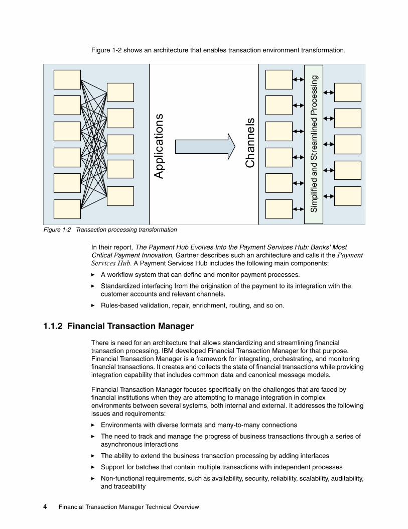
Figure 1-2 shows an architecture that enables transaction environment transformation.
Figure 1-2 Transaction processing transformation
In their report, The Payment Hub Evolves Into the Payment Services Hub: Banks' Most Critical Payment Innovation, Gartner describes such an architecture and calls it the Payment Services Hub. A Payment Services Hub includes the following main components:
� A workflow system that can define and monitor payment processes.
� Standardized interfacing from the origination of the payment to its integration with the customer accounts and relevant channels.
� Rules-based validation, repair, enrichment, routing, and so on.
1.1.2 Financial Transaction Manager
There is need for an architecture that allows standardizing and streamlining financial transaction processing. IBM developed Financial Transaction Manager for that purpose. Financial Transaction Manager is a framework for integrating, orchestrating, and monitoring financial transactions. It creates and collects the state of financial transactions while providing integration capability that includes common data and canonical message models.
Financial Transaction Manager focuses specifically on the challenges that are faced by financial institutions when they are attempting to manage integration in complex environments between several systems, both internal and external. It addresses the following issues and requirements:
� Environments with diverse formats and many-to-many connections
� The need to track and manage the progress of business transactions through a series of asynchronous interactions
� The ability to extend the business transaction processing by adding interfaces
� Support for batches that contain multiple transactions with independent processes
� Non-functional requirements, such as availability, security, reliability, scalability, auditability, and traceability
Sim
plifi
ed
and
Str
eam
line
d P
roce
ssin
g
Ch
anne
ls
App
licat
ion
s
4 Financial Transaction Manager Technical Overview

Financial Transaction Manager provides a framework through which management of the integration of existing and new applications and services can be achieved through a “financial transaction-aware” integration platform. Financial transaction aware implies that the integration platform has a knowledge and context of the financial transaction.
Financial Transaction Manager supports the following services:
� Makes accessible services that can be reused for many processes
� The incorporation of a comprehensive set of accelerators that enables rapid assembly, integration, and modification of business processes
� The maximization of IBM market-leading service-oriented architecture (SOA) foundation products
Financial Transaction Manager is built on the following key pillars that can help realize the goals of the wanted architecture:
� Canonical format to represent a business transaction
This pillar for financial transaction processing includes interfacing to multiple systems with disparate formats. As shown in Figure 1-2 on page 4, when the number of channels (c) and applications (a) increase, the complexity of integration increases correspondingly (c x a). The only way to simplify this complexity is to transform from the source formats to a canonical format that represents the business transaction and then to transform from the canonical to the target format. This shift simplifies the integration to a more manageable level (c + a).
Financial Transaction Manager provides this canonical format that is called internal standard format (ISF). This format is based on the financial industry standard ISO 20022. By using this format, a comprehensive set of business objects for financial markets can be made available and used to integrate with other interfacing systems. When mapped to ISF, the message can be transformed to any interface for any business purpose.
� Model-based transaction processing engine to streamline integration
This pillar for financial transaction processing includes exchange of business messages between the interacting systems, mostly in an asynchronous fashion. Traditionally, this interaction was point-to-point, where individual systems are coupled to each other, which causes the processes to become rigid because of the interdependencies and at the same time, difficult to trace.
Financial Transaction Manager provides the Transaction Processing Engine that automatically orchestrates the financial business process by referring to a defined process model. The process model is based on the concept of Finite State Machines (FSM) and is modeled by using IBM Rational® Software Architect’s state machine diagrams. As the transaction processing engine drives the lifecycle of the business process, it tracks the process state in a data model, thereby inherently providing process state visibility.
Financial Transaction Manager is composed of the following core components:
� Internal standard format� Data model� Model-based Transaction Processing Engine� Operations and Administrative Console (browser-based user interface)� Prebuilt message transformations (such as, SWIFT to or from ISF)� Set of services to expedite financial process orchestration� Prebuilt business activity monitoring dashboards� Preferred practices, development methodology, and programming guide� Sample applications that show the framework
Chapter 1. Anatomy of an IBM Financial Transaction Manager solution 5

High-level architectureFor further understanding of the architecture, consider the high-level diagram of Financial Transaction Manager that is shown in Figure 1-3.
Figure 1-3 Financial Transaction Manager architecture
Data store (DB2)In Figure 1-3, the data store is an IBM DB2® database (but it also can be Oracle or other database) that is based on the Financial Transaction Manager Data Model. It is used to store operational and configuration data.
For more information about the data model, see 1.2.2, “Data model” on page 14.
Transaction Processing Engine that is running on WebSphere Message BrokerThe main transaction processing is centered around the Transaction Processing Engine, which runs on WebSphere Message Broker and is responsible for the following processing:
� Receiving all business transactions (messages, files, and so on)
� Persisting operational data to the data store
� Orchestration of the process for the business transactions (by using a Finite State Machine model that is created in RSA)
� Producing outbound messages, files, and so on
WebSphere Application Server
Operations and Administrative Console
Monitoring, Management, Configuration
IBM Business Monitor
Business Monitor Dashboard
STP Rates, Hosted Service KPI etc.WebSphere Message Broker
Transaction Processing Engine
Lifecycle management, Event processing, Transactions, Actions, Routing, Rules etc.
Bank Internal Systems Shared Services SWIFT
Channels
DB2Configuration,
Process models etc.Transaction (ISF)
Audit etc.
Deploy Export
Config Data
Opterational
Data
Operator
Commands
KPI Events
CSM
Opt
erat
iona
l D
ata
Con
fig D
ata
WebSphere Message Broker Toolkit
Action Flows Maps
Rational Software Architect
Process models Configurations
6 Financial Transaction Manager Technical Overview

The Transaction Processing Engine consists of a combination of Financial Transaction Manager core components and solution-specific components. Although the core components are shipped without modification, the solution-specific components are developed as part of the solution development.
For more information about Transaction Processing Engine, see 1.2.3, “Transaction Processing Engine” on page 29. For information about the design and development of a Financial Transaction Manager solution, see Chapter 2, “Design and development methodology overview” on page 43.
WebSphere Application Server and Operations and Administrative ConsoleOperations and Administrative Console (OAC) is a web application that is deployed on WebSphere Application Server. It provides a user or operator view of the Financial Transaction Manager database. OAC can be used to monitor, configure, and control any number of deployed Financial Transaction Manager applications.
IBM Business Monitor and Business Monitor DashboardBusiness Monitor Dashboard, which is running on IBM Business Monitor, is a business activity monitoring dashboard and is used for monitoring key performance indicators of the Financial Transaction Manager system.
WebSphere Message Broker ToolkitWebSphere Message Broker Toolkit is used to develop build artifacts and deploy to broker.
For more information about WebSphere Message Broker Toolkit, see Chapter 5, “Using WebSphere Message Broker Toolkit to produce build artifacts” on page 131.
Rational Software ArchitectRational Software Architect is used to create design artifacts to build the process model (as a set of Finite State Machines), and to prepare configuration data, which can be exported as scripts that are ready to deploy to the database.
For more information about Rational Software Architect, see Chapter 3, “Producing design artifacts by using Rational Software Architect” on page 57.
Chapter 1. Anatomy of an IBM Financial Transaction Manager solution 7

Sample payment scenarioConsider the following sample payment scenario.
Figure 1-4 shows the sample payment scenario. In this scenario, Internet Banking Channel system starts a payment by starting the Credit Transfer Process use case. This use case, which is implemented in Financial Transaction Manager, interacts with the Core Banking System and a payments gateway to complete the functionality.
Figure 1-4 Sample payment scenario use case diagram
Note: This payment scenario is used only as an example. You can also use Financial Transaction Manager to process other types of financial transactions.
Internet Banking Channel
Core Banking System
Core Banking System
GatewayGateway
Credit Transfer Orgination
Core Banking Request
Gateway Request
Credit Transfer Process
8 Financial Transaction Manager Technical Overview

Figure 1-5 shows the sequence of execution that occurs to complete the use case. Internet Banking Channel starts a single credit transfer request, which is a service that is made available by the Credit Transfer Process.
Figure 1-5 Sample payment scenario sequence diagram
Chapter 1. Anatomy of an IBM Financial Transaction Manager solution 9

This service is hosted in Financial Transaction Manager and runs the processing for the payment by using a Finite State Machine that models the orchestration. The processing starts with Financial Transaction Manager mapping the incoming payment business message from the Internet Banking Channel’s format to Financial Transaction Manager’s canonical format ISF. At this time, it also stores the incoming transaction in its data store. ISF holds all the data that is possible for any type of payment and, therefore, is the canonical format.
Financial Transaction Manager is based on Events Driven Architecture (EDA). After the input message is imported, it continues processing the transaction by raising events and then handling them appropriately by performing business logic as defined in the Finite State Machine. As the processing continues, the processing state is maintained and tracked in Financial Transaction Manager’s data store.
After mapping the incoming business message, Financial Transaction Manager then validates the message and, on successful validation, sends a request to the Core Banking System. This is done automatically after mapping the business transaction’s ISF that is stored in the Financial Transaction Manager’s data store to the Core Banking System’s format.
Starting any business function is done by transforming from ISF. This standardized interfacing decouples the process from the participating interfaces and the interface can be reused across other services, which allows for the creation of reusable utility services. Financial Transaction Manager then waits for the Core Banking System to return the response and, on receipt of the response, again maps the incoming message and continues processing, as shown in Figure 1-5 on page 9.
Part of the response is the automatic correlation of the response to the request and the original Credit Transfer Process. This automatic correlation allows tracing between the different legs of processing. Thus, Financial Transaction Manager can automatically process a financial transaction as defined by its Finite State Machine model and automatically integrate with the interfacing systems.
1.1.3 Usage scenarios
In this section, we describe some of the usage scenarios of Financial Transaction Manager. The scenarios that are described are a summary of the more common scenarios.
Payments BusSimplifying and standardizing payments across the many lines of businesses (LOBs) is a significant challenge for many large financial institutions across the world.
As financial institutions become regional or global, the number of payment types that they must provide to their customers (such as, the local country-specific low value ACH or the high value RTGS schemes) increase. Then, as the services across the LOB converge, it becomes imperative that these payment services are available for all customers.
Hence, a common requirement that is emanating is the ability to centralize the payment processing in one infrastructure that makes available all the payment services.
Note: The service is made available be using ISF. The use of the service requires transforming from the consumer’s format to ISF only (which is a key benefit) because the service is not coupled to the channel. It is easy to make the service available to other channels and realize the goal of standardized interfacing.
10 Financial Transaction Manager Technical Overview

Figure 1-6 shows the concept of Payments Bus, which is based on Financial Transaction Manager.
Figure 1-6 Payments Bus architecture
In Figure 1-6, the Payments Bus Platform that is built on Financial Transaction Manager forms the heart of payment processing and acts as the financial transaction-aware integration layer. This layer makes available the payment services that allow the channel applications to use them, which is indicated as Collection Service and Payment Service of the left side of the figure. In essence, this layer makes available the transaction processing as SOA services.
This layer can provide cross cutting functionality, which is needed by all payment types, such as logging, bulking, debulking, routing, orchestration, protocol, and format conversions, while making use of payment processors, which can provide the actual processing of the payment types. The payment processors can be part of this same layer or used from existing applications or other investments.
The advantage of this kind of architecture is that although the Payments Bus Platform provides the integrated, unified base set of reusable services, the actual payment type processing can be done by specialized payment processors.
This architecture provides the following key features:
� Interfacing by using a Canonical Format (ISF), which allows the payment services to be made available to any channel and, at the same time, allows for the reuse of existing services and utilities for channels and payment types
� Fit for purpose payment processor, which can be procured off the shelf, built bottom up, or used from existing investments
SWIFT
Logging Authentication Format Verification
Duplicate Check
Payments Bus (Financial Transaction Manager)
Regional / LOB Systems
Internet Banking
Branch Banking
Corporate B2B Integration
Regional / LOB Systems
Internet Banking
Branch Banking
Corporate B2B Integration
Regional
Local ACH Scheme
Local RTGS Scheme
Regional
Local ACH Scheme
Local RTGS Scheme
Regional / LOB Systems
Core Banking General Ledger Other Back Office Systems
RoutingCanonical Interface
Bulking and Debulking Orchestration
Format Transformation Protocols
Paym
ent Ser
vice
Payment Processors
Low Value Payment Processors
SWIFT Processor
High Value Payment Processors
Col
lect
ion
Ser
vice
Chapter 1. Anatomy of an IBM Financial Transaction Manager solution 11
� End-to-end payment process tracking capability
� Architecture can be rolled out in a phased approach, which transforms payment type by type or according to any other priority
Modernizing MERVA processingSince the 1980s, many financial institutions all over the world are using IBM Message Entry and Routing with Interfaces to Various Applications (MERVA) for business-critical applications in their financial transactions and messaging solutions infrastructure. SWIFT gateway and enterprise application integration (EAI) are two of the primary use cases of MERVA. However, since the retirement of X.25 protocols, MERVA was not adapted for the newer SWIFTNet IP. Many financial institutions are contemplating modernizing their MERVA platform.
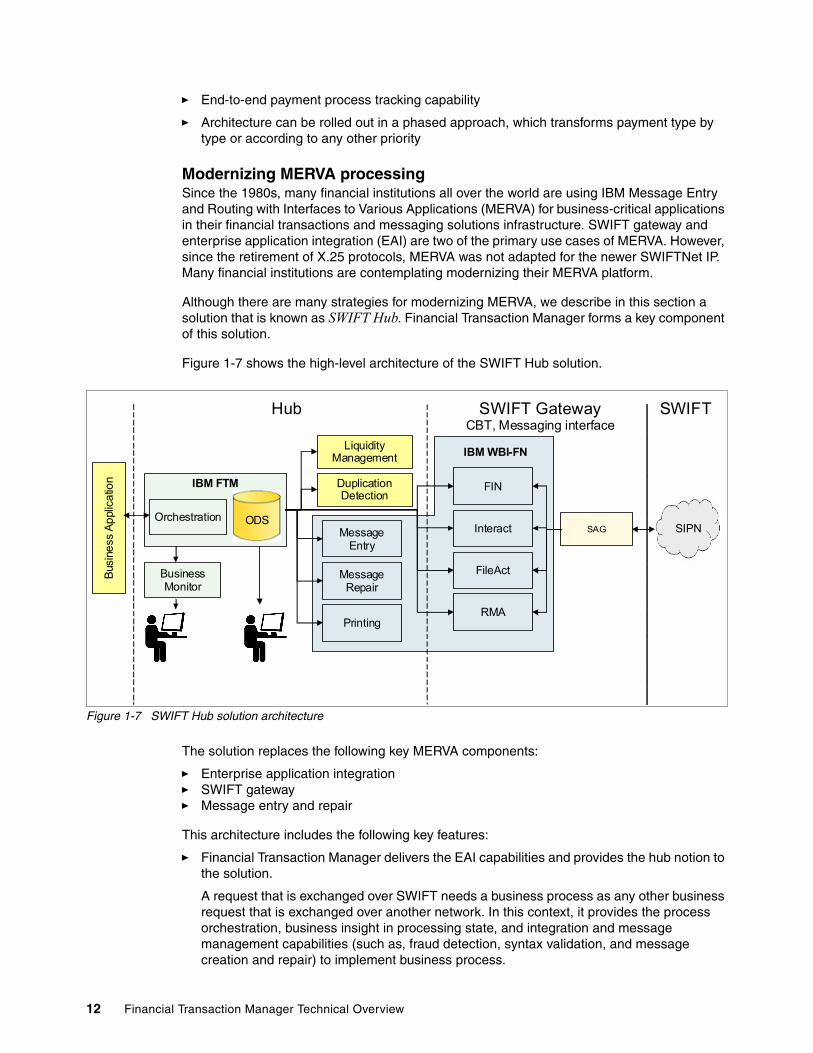
Although there are many strategies for modernizing MERVA, we describe in this section a solution that is known as SWIFT Hub. Financial Transaction Manager forms a key component of this solution.
Figure 1-7 shows the high-level architecture of the SWIFT Hub solution.
Figure 1-7 SWIFT Hub solution architecture
The solution replaces the following key MERVA components:
� Enterprise application integration� SWIFT gateway� Message entry and repair
This architecture includes the following key features:
� Financial Transaction Manager delivers the EAI capabilities and provides the hub notion to the solution.
A request that is exchanged over SWIFT needs a business process as any other business request that is exchanged over another network. In this context, it provides the process orchestration, business insight in processing state, and integration and message management capabilities (such as, fraud detection, syntax validation, and message creation and repair) to implement business process.
Message Entry
IBM FTM
Orchestration
Business Monitor
Bus
ine
ss A
ppl
ica
tion
Liquidity Management
Duplication Detection
Message Repair
Printing
FIN
Interact
FileAct
RMA
SAG
IBM WBI-FN
Hub SWIFT GatewayCBT, Messaging interface
SWIFT
ODSSIPN
12 Financial Transaction Manager Technical Overview

� IBM WebSphere Business Integration for Financial Networks provides the gateway aspect for the solution by supporting the SWIFT messaging services FIN, InterAct, and FileAct. In addition, it provides other features, such as relationship management, adherence to the SWIFT business standards, and message entry and repair.
1.2 Financial Transaction Manager solution key concepts
In this section, we describe the development methodology for Financial Transaction Manager at a high level to highlight important components. These concepts are described in greater detail in later sections.
In this section, we describe the following topics:
� Development methodology� Data model� Transaction Processing Engine� Solution-specific artifacts
1.2.1 Development methodology
In this section, we describe the development methodology at a high level to introduce the important concepts, which are used in subsequent sections.
The Financial Transaction Manager Development Methodology provides a formal methodology to follow for the design and development of a Financial Transaction Manager solution. It addresses activities around the production of the design and development artifacts that make up a Financial Transaction Manager solution.
Design activities center around the following tasks:
� Capture interface details and map formats to the ISF.
� Capture use case details, which are represented as sequence diagrams, from which the process model design is refined to produce details of the operational data objects and a Finite State Machine model.
Development activities center around the following tasks:
� Develop mappers to transform between external formats and the ISF.
� Develop WebSphere Message Broker artifacts, which are deployed within the Transaction Processing Engine for processing business logic.
For more information, see the following resources:
� For more information about the development methodology, see Chapter 2, “Design and development methodology overview” on page 43.
� For information about process and configuration modeling, see Chapter 3, “Producing design artifacts by using Rational Software Architect” on page 57.
� For more information about mapping and the ISF, see Chapter 4, “Mapping” on page 85
� Chapter 5, “Using WebSphere Message Broker Toolkit to produce build artifacts” on page 131.
Chapter 1. Anatomy of an IBM Financial Transaction Manager solution 13
1.2.2 Data model
Financial Transaction Manager is a financial transaction orchestration framework and depends on its data model to run the processing.
Data model is composed of the following types of data:
� Configuration data� Operational data
Configuration data composes mainly the following attributes:
� Configuration details of interfaces, formats, schedules, parameters, and so on� Process and event metadata (Finite State Machine)
These configurations are modeled in Rational Software Architect and then exported by using export wizards that are ready for deployment to the data store. At run time, Transaction Processing Engine reads this data and runs the processing and back-end integrations. Apart from this, configuration data (except process and event metadata) can also be managed by using Operations and Administrative Console.
Operational Data contains the runtime process transaction information that is called process instance data. The following types of operational data are available:
� Operational objects (such as Transaction, Transmission, Batch, and Fragment) that are used to persist the details of messages and transactions that are being processed and to track the status of these objects through their lifecycle
� Events instance data that record milestones that are met through the process orchestration (not all events are recorded and this is configurable by event type)
� Relationship data and other information, such as logging and error information
This data is created and updated as part of transaction processing in the Transaction Processing Engine. Operations and Administrative Console provides read-only access to this data for monitoring, transaction inquiry, and drill down.
Multiple application and versioning supportBefore wed describe the data model, it is important to understand how the data is partitioned in the database instance. Financial Transaction Manager supports partitioning of data into a “scope” that is called Application (table name: APPLICATION).
All of the Configurational and Operational data is “scoped” under an Application. This process allows the creation of multiple Financial Transaction Manager applications (such as Remittance application, and Trade Finance application) in the same database instance. All of the data that is related to the applications is segregated from each other because of this notion of scope.
In addition to scoping by applications, Financial Transaction Manager supports Versions (table name: APP_VERSION) to control changes to the configuration data. By using Versions, configuration data is further scoped so that at any point, only one version of the configuration is effective. The effective configuration version is explicitly chosen as part of runtime configuration of WebSphere Message Broker flows. This process allows a phased approach when the configuration changes are rolled out.
As Financial Transaction Manager’s transaction orchestration framework runs, which is based on the data model, it must be parameterized to choose the best application and version.
14 Financial Transaction Manager Technical Overview

Figure 1-8 shows the concept of multiple applications and versions.
Figure 1-8 Applications and versions
In Figure 1-8, there are two applications (Application 1 and Application 2) that scope all their data underneath them.
The operational data that is shown in the figure indicates all of the data that is related to a process run, including the ISF data of the messages. This data is scoped directly inside the application and is insulated from other applications. Applications can also be used as a filter criteria to restrict access rights to data for the users of the UI.
The processing configuration data (such as the Finite State Machine and the interface configuration) are all further scoped inside versions. A single version is considered effective at any one point (Version 3 for Application 1 and Version 4 for Application 2). The version configuration entries permit further controls; for example, enabling and scheduling for the runtime configuration, data cache refresh, and overrides for event logging.
For more information about multiple applications and version support, in the Financial Transaction Manager 2.1 Information Center, browse to Financial Transaction Manager overview Data model overview Multiple applications and versions section.
Interface ConfigurationAs part of transaction processing, Financial Transaction Manager uses configuration data to acquire details about each interface that the Transaction Processing Engine uses to manage the interaction with back-end applications.
Financial Transaction Manager Database Instance
Application 2Version 1
Configuration
Version 2
Configuration
Version 3
Configuration
Version 4 (Effective)
Configuration
Operational Data Operational
Data Operational Data Operational
Data
Application 2Version 1
Configuration
Version 1
Configuration
Version 2
Configuration
Version 2
Configuration
Version 3
Configuration
Version 3
Configuration
Version 4 (Effective)
Configuration
Version 4 (Effective)
Configuration
Operational Data Operational
Data Operational Data Operational
Data
Application 1Version 1
Configuration
Version 1
Configuration
Version 2
Configuration
Version 2
Configuration Version 4
Configuration
Version 4
Configuration
Version 3 (Effective)
Configuration
Version 3 (Effective)
Configuration
Operational Data Operational
Data Operational Data Operational
Data
Chapter 1. Anatomy of an IBM Financial Transaction Manager solution 15

Figure 1-9 shows interface configuration.
Figure 1-9 Financial Transaction Manager interface configuration concepts
Figure 1-9 shows the following concepts about interface configurations:
� Service
Service (table name: SERVICE) corresponds to a service that is provided by Financial Transaction Manager; for example, Payment Processing and Remittance Processing. It provides a mechanism to group the interfaces that are involved in the provision of that service. It groups the service participants.
� Service participant
Service participants (table name: SVC_PARTICIPANT_BASE and OBJ_BASE) abstract a single logical interface that participates in a Financial Transaction Manager service. It signifies the typical characteristics of an interface (for example, the logical role that is played by the interface, such as Gateway and Payment Source) and the rank of the interface (primary or secondary). These characteristics play an important role during routing.
Because the state of the service participant can change over time (such as scheduled opening and closing times), it facilitates the semantics of a lifecycle object. This object is controlled by a Finite State Machine, which models its behavior over time. It also groups the input and output channels that are associated with the interacting interface.
Service Participant (Core Banking)
Map
ISF
Map
ISF
Input Format
Output Format
Map
ISF
Map
ISF
Inpu
t C
han
nel
Ou
tput
Cha
nne
l
Service Participant (Internet Banking Channel)
Inpu
t F
orm
atO
utp
ut
For
mat
Map
ISF
Map
ISF
Map
ISFInput Channel
Output ChannelService
(Payment Service)
16 Financial Transaction Manager Technical Overview

� Channel
Channels (table name: CHANNEL) abstract the unidirectional physical details of an interface. For example, the physical communication protocol and format of the endpoint. It associates information that is related to the format of the endpoint and the mapper. This information is used to convert between the endpoint format and ISF. Details about both input and output channels are specified for a service participant.
� Format
Formats (table name: FORMAT) abstract the format of an endpoint and is associated with a Channel. While mapping into ISF during the mapping process, this information is used to parse the input message and feed into the Inbound Mapper. Similarly, when mapping from ISF during outward mapping process, this information is used to build an output message to be sent to the external service participant.
� Mapper
Mappers (table name: MAPPER) abstracts the mapper that is required to transform between the endpoint format and ISF. They identify a real WebSphere Message Broker deployed mapper artifact and the framework uses this information to automatically start the mapper at run time. Mappers can be inbound or outbound and, depending on direction, either inbound or outbound mappers are started.
� Involved Parties (table name: PARTY), which are not indicated in the diagram, identify any individual, organization, organizational unit, or a system about which the financial institutions want to keep information. Typically, a channel is associated with a party and all messages that are emanating from the channel are automatically associated with the party. Based on this, user access control rights can be defined when operational data is accessed in the Operations and Administrative Console.
Figure 1-10 shows the relationship between the various interface configuration concepts.
Figure 1-10 Interface configuration class diagram
Chapter 1. Anatomy of an IBM Financial Transaction Manager solution 17

Additional configuration information, which is related to the calendar (working days and holidays) and schedules that are associated with the Parties, can also be configured.
Calendar Group (table name: CALENDAR_GROUP) abstracts a calendar that groups the calendar days or schedules with the details stored in Calendar Entry (table name: CALENDAR_ENTRY) and Schedule Entry (table name: SCHEDULE_ENTRY) records.
These calendar groups can then be shared with the parties by using Calendar Group Party Relationships (table name: CAL_PARTY_REL).
Schedules can also be shared with activities that must be performed at specific times. Such activities are represented by Scheduled Tasks (table name: SCHEDULER_TASK_BASE) and the relationship that is maintained in table CAL_OBJ_REL.
For more information about scheduled activities, see 9.12, “Scheduled activity pattern” on page 415.
Finally, Financial Transaction Manager allows the storing of parameter data as Values (table name: VALUE) and Classifications (table name: CLASSIFICATION). Values are used for storing configuration values and name-value pairs by categories. Classification identifies a value or qualifier that is a member of a category of data.
For more information about configuration data, see the Financial Transaction Manager 2.1 Information Center at this website:
http://www-01.ibm.com/support/docview.wss?uid=swg27038668
Browse to Financial Transaction Manager overview Data model overview Configuration Data.
Finite State Machine configurationFinite State Machine (FSM) is a computational model that is used to define the lifecycle of objects. FSM models are modeled in Rational Software Architect as State Machine Diagrams and then exported and deployed to the data store. The models are then read by the Transaction Processing Engine for running the process model. For more information, see 1.2.3, “Transaction Processing Engine” on page 29.
For more information about modeling FSM by using Rational Software Architect, see Chapter 3, “Producing design artifacts by using Rational Software Architect” on page 57.
Finite State Machine (table name: FSM), at a high level, is composed of a set of States (table name: FSM_STATE_REL) and state changes called Transitions (table name: FSM_TRANSITION). Transitions specify how the state, of the lifecycle object, transitions.
Transitions are composed of the following items:
� Specifications of a from state and a to state of a lifecycle object� The event that causes the transition to occur� The Actions that are to be started on completion of the state transition
18 Financial Transaction Manager Technical Overview
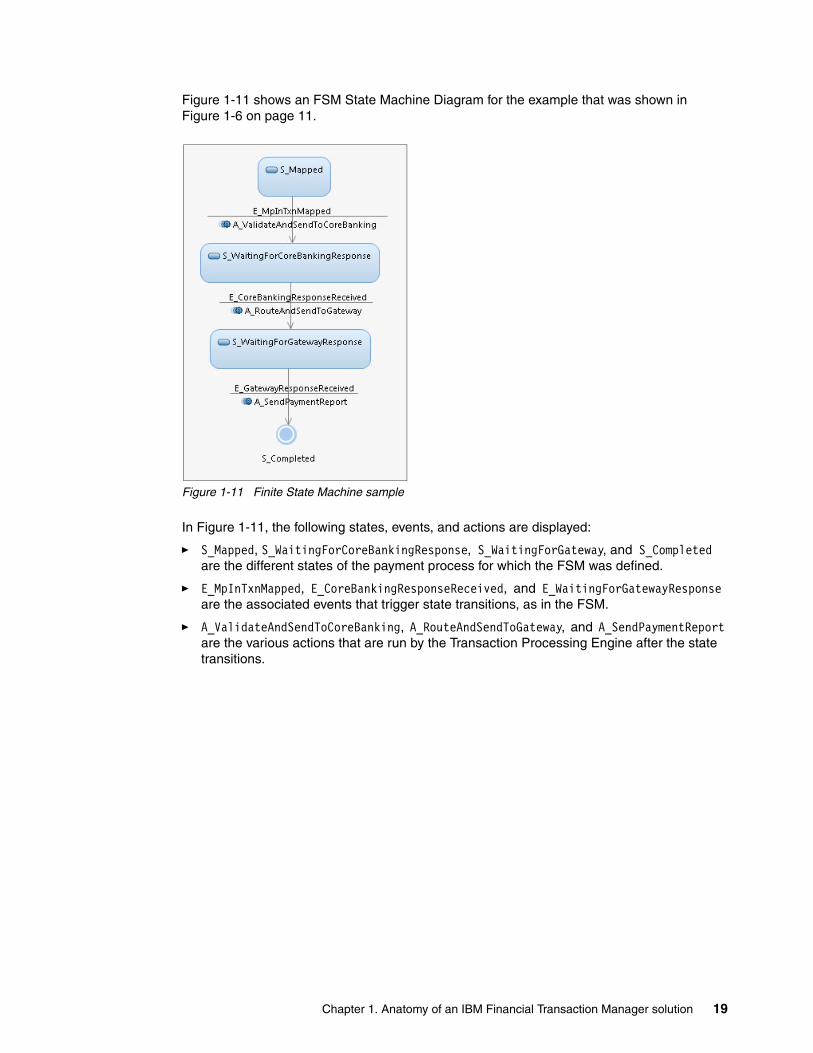
Figure 1-11 shows an FSM State Machine Diagram for the example that was shown in Figure 1-6 on page 11.
Figure 1-11 Finite State Machine sample
In Figure 1-11, the following states, events, and actions are displayed:
� S_Mapped, S_WaitingForCoreBankingResponse, S_WaitingForGateway, and S_Completed are the different states of the payment process for which the FSM was defined.
� E_MpInTxnMapped, E_CoreBankingResponseReceived, and E_WaitingForGatewayResponse are the associated events that trigger state transitions, as in the FSM.
� A_ValidateAndSendToCoreBanking, A_RouteAndSendToGateway, and A_SendPaymentReport are the various actions that are run by the Transaction Processing Engine after the state transitions.
Chapter 1. Anatomy of an IBM Financial Transaction Manager solution 19

Figure 1-12 shows the class diagram that explains the relationship between the following related concepts:
� FSM� FSM state� Transition� Event type
Figure 1-12 FSM-related configurations class diagram
FSM aggregates FSM states and transitions. In addition, it has a key property that is used during FSM processing called object selection template. Object selection template stores an SQL statement. The statement retrieves the subset of lifecycle objects that must undergo state transitions (as defined by the FSM) with the column data for FSM processing.
Transition features associated current states, target states, and event types that trigger the transition. In addition, it has the following key properties that are used during FSM processing:
� Override Selection stores an SQL statement, which is meant to override the Object Selection Template. Generally, it is expected that although both Object Selection Template and Override Selection fetch the same set of lifecycle objects, Override Selection is more specific in terms of the column data that is fetched as compared to Object Selection Template. Typically, this is used to select alternative column data or to join other tables for specific transitions.
� Event Filter is a WebSphere Message Broker ESQL boolean expression that might reference the Event Instance context data. This data is evaluated to determine whether the event might cause the transition to process.
� Object Filter is a set of other predicates that are in the WHERE clause. This clause is used to match the objects that are transitioned based on the event instance context data. Object Filter is combined with the effective Object Selection Template or Override Selection to produce an SQL statement to retrieve the objects that are transitioned by the event.
� FSM Action is the name of the action that must be run after the transition is processed.
20 Financial Transaction Manager Technical Overview

EventsFinancial Transaction Manager is based on events-driven architecture and events form the lifeline of business message processing. Practically, events are lightweight messages that conform to common base events XML schema and are fired during the business message processing. They mark that something significant occurred. Typically, events are a milestone in the processing and are modeled to reflect that occurrence (such as Transaction Mapped and Gateway Response Received).
Financial Transaction Manager classifies Events as the following types:
� Internal events drive the business processing. They are fired and placed on an events queue from where the event processing flow processes them.
� External events are typically published to external agents, such as business activity monitoring agents; for example, IBM Business Monitor. They are triggered by an internal event, for which a publication rule was included in the event metadata and published. These triggered events are then handled by the external applications.
For more information about publishing external events, see the Financial Transaction Manager 2.1 Information Center and browse to Application programming External Event Publishing.
Internal eventsIn this section, we describe internal events. Event instances, which are individual event messages, store the following data:
� Event type, which specifies what milestone occurred� Event context, which specifies the context information that is related to the milestone� Time stamp, which specifies when the milestone occurred
Within the event processing flow, events provide the triggers to transition objects (update status) and perform business processing. Event data is typically used to filter events and to identify the lifecycle objects for processing. Although events are a runtime concept, Financial Transaction Manager also stores event-related data in the data model.
The following information is stored in the data model:
� Event configuration data� Event instance data, which forms part of the operational data
Configuring a state to an alertable state: A state can be configured to be an alertable state. In this situation, when a lifecycle object transitions to such a state, the object is flagged automatically to the operator in Operations and Administrative Console. Optionally, a state can also be configured to allow operator controls for the object, such as resolution actions.
Chapter 1. Anatomy of an IBM Financial Transaction Manager solution 21

Figure 1-13 shows the various events-related concepts that pertain to both configuration and operational data. The publication rules are not shown.
Figure 1-13 Events-related concepts
Figure 1-13 shows the following concepts:
� Event type� Event expected context� Event
Typically, event type and event expected context are modeled as part of the Rational Software Architect modeling and is exported into the data model by using export wizards.
Event type specifies the type of the event and includes configuration for some of the following key characteristics of events processing:
� Event logging specifies whether the event instances of this type are logged as operational data.
This is a fine-grained configuration at the level of individual event types. However, this property setting can be overridden by the event logging override setting at the configuration version level, which provides an override setting for all the event types.
� Render As Message specifies how the event is processed by the events processing flow. For example, should it be processed inflow with the current run or separately by placing the message on an events queue and processing it subsequently.
If its value is true, the messages are put on the events queue, which is then picked up by the events processing flow as part of a separate unit of work. However, if it is false, the event is processed inflow as part of the current unit of work.
� Aggregate Threshold specifies the maximum number of event instances that can be aggregated to a single event.
Event expected context specifies the type of context data that can be contained in the event instance. In addition, it has another key property that affects the characteristics of event processing, called aggregatable flag.
Aggregatable flag specifies whether values of the event context data can be aggregated. Aggregation is a mechanism that allows two or more events that are raised to be merged into one for more efficient processing, the threshold of which is controlled by the aggregate threshold property of event type.
22 Financial Transaction Manager Technical Overview

Events that are raised during the run of an application usually contain multiple pieces of context data that provide detailed information about the context in which the event instance was raised. When many events are raised together, they often contain the same information with just one or two context values being different. In such situations, these events can be aggregated if the aggregatable flag is set for the context elements for which the values differ.
Figure 1-14 shows the event aggregation concept.
Figure 1-14 Event aggregation
For more information about event aggregation, see the Financial Transaction Manager 2.1 Information Center. Browse to Designing applications Application analysis and design tutorial Event Aggregation.
Figure 1-14 also shows the event operational data (event instances) that are logged. Event logging maintains a relationship to all the lifecycle objects that changed their state because of the event instance. This information can be viewed by the operator by using the Operations and Administrative Console (OAC). For performance reasons in a production environment, the events that occur during normal processing should not be logged.
Operational dataAt run time, Financial Transaction Manager creates operational data to process the financial business transactions and messages.
This data is used for tracking the following items:
� The raw data transmissions between the financial service and the external systems that uses the various types of physical communication mechanisms (such as, WebSphere MQ queue, and file transfer)
� Optionally, business content that can be contained in batches
� Individual business content
Chapter 1. Anatomy of an IBM Financial Transaction Manager solution 23

Figure 1-15 shows a scenario that reflects operational data.
Figure 1-15 Transmission, batches and transaction
Financial Transaction Manager abstracts the following concepts, as shown in Figure 1-15:
� Transmission represents a unit of raw data interchange with external systems for a particular business purpose. For example, a message on WebSphere MQ queue. It optionally stores the raw data that is exchanged.
� Batch represents an optional logical grouping of transactions that are exchanged within the same transmission.
� Transaction represents a single unit of business activity that corresponds to a business message for a business purpose. For example, payment, order, remittance, and acknowledgement.
These operational data is created and updated as the transaction processing flow runs.
Typically, a service is composed of many legs of related business message exchanges with the service participants and the transaction or transmission corresponding to the master transaction or transmission. The master transaction or transmission is the first business message that starts the service.
Operational data can be inquired about and tracked from the Operations and Administrative Console.
Service Participant (Internet Banking
Channel)
Inpu
t F
orm
atO
utpu
t F
orm
at
Map
ISF
Map
ISF
Input Channel
Output Channel
Service Participant (Internet Banking
Channel)
Inpu
t F
orm
atO
utpu
t F
orm
at
Map
ISF
Map
ISF
Map
ISF
Input Channel
Output Channel Service (Payment Service)
Transmission
Transaction
Batch n
24 Financial Transaction Manager Technical Overview

Figure 1-16 shows the relationship between the following transactional concepts:
� Object base� Transmission� Transaction and its sub types, payment, and securities transactions� Batch� Fragment� Service participant
Figure 1-16 Main operational data class diagram
Object baseFinancial Transaction Manager abstracts any object that requires Finite State Machine processing by an object called Object Base (table name: OBJ_BASE). Inside Object Base, Financial Transaction Manager stores the following information that is related to the current state:
� Any operational data that requires state processing conceptually inherit from Object Base and are considered lifecycle objects.
� Object base has a Type property that specifies the type of lifecycle object, such as transmission, transaction, and batch. In addition, object base has another property that is called Sub Type that denotes the business purpose of the lifecycle object. Typically, the Sub Type determines the Finite State Machine that is used to process the operational data.
� All the data that pertains to the object types (transmission, transaction, and batches) are contained in the conceptual inheritance hierarchy, with object base containing the identity, type, and state information. Object base also contains pertinent lower-level information (raw data, ISF, and so on) that is contained in the transmission and transaction respectively.
Chapter 1. Anatomy of an IBM Financial Transaction Manager solution 25

TransmissionAt run time, each message that arrives is recorded as a Transmission (table name: TRANSMISSION_BASE and OBJ_BASE) for which there is one object base record and one transmission record. If the Channel is configured to log raw data, the raw data of the message is recorded in the transmission.
BatchIf an inbound or outbound physical transmission contains batches, there is an object base and batch record pair for each batch that is contained in the physical transmission (table name: BATCH_BASE and OBJ_BASE). Batch then aggregates all of the contained transactions within it. Financial Transaction Manager also supports nested batches. Batch summary information is also stored in the batch record.
TransactionEach individual transaction in the physical transmission (or batch) is recorded by an object base and transaction record pair (table name: TRANSACTION_BASE and OBJ_BASE).
A transaction includes the following key properties:
� ISF data that pertains to the mapped business message
� Financial Transaction Manager is a framework for processing financial data. To cover financial information processing, it further extends the transaction concept by inheriting from it and creating further sub concepts for the financial transaction areas, such as payments and securities.
� For processing payment information, a sub concept that is called payments (table name: TXN_PAYMENT_BASE) and derived from transaction is available. In addition to the transaction information, it extracts payment-specific information from the mapped ISF message (payment type, bank code, account information, amount of transfer, currency of amount, and so on) and stores it in the table.
� Similarly, for processing security transactions, there is a sub concept called Securities (table name: TXN_SECURITIES_BASE).
Service participantThough service participant is not considered operational data, it is represented in Figure 1-16 on page 25 for completeness sake, as the service participant also implements lifecycle semantics.
For more information about these concepts, see the Financial Transaction Manager 2.1 Information Center. Browse to Financial Transaction Manager overview Data model overview Operational data types.
Relationships in operational dataProcessing a financial business process involves the processing of many related business messages. For example, consider the scenario that is described in Figure 1-4 on page 8. Table 1-1 on page 27 summarizes the business messages that are exchanged between Financial Transaction Manager (credit transfer process) and all the interfacing service participants in the scenario.
26 Financial Transaction Manager Technical Overview

Table 1-1 Business message exchange between scenario participants
The processing of the first message (Credit Transfer Request) is related to processing of all the other messages and the relationships must be maintained. To complete the business process that is started by Credit Transfer Request, all of the subsequent business messages must be orchestrated and processed. Because the processing of each business message translates to a transaction, Financial Transaction Manager creates transactions for every business message. Financial Transaction Manager also maintains the business relationship between these related transactions.
Figure 1-17 shows the various transaction and transmission objects and their business relationships.
Figure 1-17 Transaction and transmission relationships
Source System Target System Business Message
Internet Banking Channel Credit Transfer Process Credit Transfer Request
Credit Transfer Process Core Banking System Core Banking Request
Core Banking System Credit Transfer Process Core Banking Response
Credit Transfer Process Gateway Gateway Request
Gateway Credit Transfer Process Gateway Response
Credit Transfer Process Internet Banking Channel Credit Transfer Process Report
Chapter 1. Anatomy of an IBM Financial Transaction Manager solution 27

The business relationship between these objects is maintained in Financial Transaction Manager by using the concept of Object to Object Relationship (table name: OBJ_OBJ_REL).
In Figure 1-17 on page 27, Credit Transfer Request is the master transaction or transmission and starts the processing of the business process. Consider the following key points:
� The relationship between an individual transaction and transmission is as in the relationship that is shown in Figure 1-16 on page 25.
� FSM for Credit Transfer Request specifies the actual processing that must occur for the process, and is as specified in Figure 1-11 on page 19.
� Processing for all other transactions (such as, sending of Core Banking Request, receipt of the Core Banking Response, or sending of the Credit Transfer Report acknowledgement) are standard and Financial Transaction Manager provides a generic set of FSM for processing these types of transactions.
Audit trailFinancial Transaction Manager supports the audit trail feature by using the operational data that can be tracked as the financial business process progresses. The audit trail is an immense help during investigations.
The following information is recorded and available:
� Transmission, transaction, and batch objects that record the details of each message or file that is sent or received.
� Transmission objects can optionally record the raw data that is received or sent.
� Transaction objects contain the ISF, which contains the business properties of the transaction.
� Relationships between the various transmission, batch, and transactions and thereafter between each of these for the different legs of processing.
� History table that records the status updates as objects progress through their process lifecycle.
� Events that provide a record of those events that are configured to be logged.
� For configuration data, the history tables that provide audit of all the configuration changes.
The audit trail is made available in the OAC and can be viewed by the operator. In addition to the transaction, transmission, and batches, and their relationship, Financial Transaction Manager supports audit trail by maintaining a set of history tables for each of the operational data.
As the business process progresses (by running the Finite State Machine and the state changes occurring), these changes are recorded in a history table. Operational data tables and history tables maintain appropriate linkages to correctly associate the audit information.
As part of audit trail recording, there are several options available that can be selectively enabled. The following levels of information can be included as part of audit information:
� Full operational data
� Operational data without LOB columns
� No detailed operational data recording, but only object base records (default)
� Only certain types of object records; for example, no history for objects of type Service Participant
28 Financial Transaction Manager Technical Overview

In addition to the audit trail that is related to state changes, the feature can also be extended. Tailor the audit trail feature to log only the required minimum amount of information. Extensive audit trails can have a negative effect on performance.
Similar to operational data audit trail, history information that is related to configuration data is also managed by Financial Transaction Manager.
For more information about history information, see the Financial Transaction Manager 2.1 Information Center. Browse to Designing applications Application analysis and design tutorial Database Size.
1.2.3 Transaction Processing Engine
Transaction Processing Engine is at the heart of the runtime framework of Financial Transaction Manager and is responsible for driving the solution, as shown in Figure 1-18.
Figure 1-18 Transaction Processing Engine
The Transaction Processing Engine features the following parts:
� Physical transmission flow� Event processing flow
Physical transmission flowPhysical transmission flow loads the incoming business message into processing and consists of the following components:
� Core physical transmission flow
� Solution-specific components that primarily include the physical transmission wrappers and inbound mappers
Transactional Data
Transmissions, Batches,
Transactions, Activity logs
Configuration Data
Process models, topology
configuration
Physical Transmission Flow
Identify Source Channel
Transform and Store
Event Processing Flow
FSM Engine
Actions (Business Logic)
Transform and Store
EventQueue
Time triggered events
Inbound Transmission
Outbound Transmission
Chapter 1. Anatomy of an IBM Financial Transaction Manager solution 29

In its entirety, physical transmission flow is responsible for the following actions:
� Handling of all inputs from external interfaces, including receiving messages by using different protocols, such as WebSphere MQ, HTTP, FTP, and email.
� Calling the appropriate mapper for handling the incoming message format and mapping to ISF
� Persisting the relevant transmission, transaction, and batch objects
� Handing over the processing to event processing flow
Core physical transmission flow takes input from the physical transmission wrapper and starts the configured inbound mappers. Starting the mappers is based on the identification of the inbound channel, and after persisting the transmission object and optionally logging the raw data. Channel identifies the inbound mapper and format. For more information about physical transmission wrapper and inbound mappers, see 1.2.4, “Solution-specific artifacts” on page 31.
After the mapping is complete, core physical transmission flow ultimately hands over the processing to the event processing flow. Event processing flow then processes the message that is based on the configured Finite State Machine. For more information about how financial message is imported into the processing, see 1.3.1, “Importing a financial business message” on page 38.
Event processing flowThe event processing flow implements the event driven orchestration of the business process for the business message. Similar to physical transmission flow, it also consists of the following components:
� Core event processing flow
� Solution-specific components that primarily include event processing wrapper, actions, outbound mappers, and emitter flows
Event processing flow reads event messages from the event queue and uses the FSM metadata. The metadata is used to identify objects whose business process relates to the event, updates the status of those objects, or starts actions to run business logic. The result of these actions can generate further events that are added to the event queue.
At a high level, event processing flow performs the following tasks when an event is handled:
� Identifies all the FSMs and the transitions that are associated with the event type of the fired event instance.
� Determines whether the transition is to be processed. This is done by evaluating the event filter that is associated with the transition against the context information in the fired event. If the evaluation expression fails, the processing is discontinued.
� Gets all the affected lifecycle objects that pertain to the FSMs by evaluating the Object Selection Template property of FSM or its override Override Selection that is configured at transition.
� Evaluation of these SQL expressions retrieves all the lifecycle objects that must be processed and the relevant column data that is needed for processing.
� The selected objects are further constrained by the Object Filter expression property in the transition.
� After transitioning the states of the selected objects to the target state (as specified in the transition), the action that is associated with the transition are started by passing to it the objects and the chosen columns data.
30 Financial Transaction Manager Technical Overview

� Action then performs the specific business logic on the lifecycle object that uses the data of the objects, which can also include the ISF data.
For more information, see the following sections:
� 1.2.4, “Solution-specific artifacts” on page 31 for information about event processing wrapper and actions
� 1.3.2, “Orchestrating the financial business process” on page 40 for more information about how messages are processed.
1.2.4 Solution-specific artifacts
In this section, we describe all of the solution-specific artifacts that must be developed to complete the solution. These include the following artifacts:
� Transmission flow wrapper� Event flow wrappers� Actions� Mappers� Emitters
For more information, see Chapter 5, “Using WebSphere Message Broker Toolkit to produce build artifacts” on page 131.
Physical transmission flow wrapperPhysical transmission wrapper is a concrete flow that must be developed to import the input of a transmission from an external system.
It is responsible for the following actions:
� Handling the transport-specific physical details of the input mechanism, such as WebSphere MQ input node, HTTP request, or a file access mechanism. The details typically include a WebSphere Message Broker transport or adapter-specific input node that is configured to receive from the interface.
� Identification of the channel that stores configuration of the inbound transmission, such as mapper, format, and other configurations.
� Feeding the input transmission to the core physical transmission flow.
� Provide a real physical output (Event/Failed) for the physical transmission flow.
Typically, a physical transmission wrapper is defined for each interface. However, it is possible to combine more than one interface with a single wrapper flow by including more than one input node on the flow. The use of separate flows provides more flexibility to change the deployment topology, more control over scalability, and more operational control to stop and start individual interfaces.
The interface configuration data must be prepared and deployed to the data store. The wrapper flow also packages appropriate outbound mapper flows and emitter flows. The physical transmission wrappers are deployed to one or more WebSphere Message Broker run groups.
Chapter 1. Anatomy of an IBM Financial Transaction Manager solution 31

Event processing wrapperEvent processing wrapper is a concrete flow that must be developed to connect the core event processing flow to the physical event WebSphere MQ queue. This wrapper flow includes a WebSphere Message Broker WebSphere MQ input node and WebSphere MQ output node that is configured for the event queue details. The wrapper flow then passes control to the core event processing flow.
Typically, a separate instance of the event processing flow is built and deployed for each deployed application. Separate Financial Transaction Manager applications use separate event queues. The event processing wrappers are deployed to one or more WebSphere Message Broker run groups and also package the relevant actions and outbound mappers.
ActionsAn action is a WebSphere Message Broker sub flow that is started by the transaction processing engine (when an FSM transition that specifies the action occurs). Actions provide the means to perform business logic to be run as the financial business processing continues. They are started in the context of those objects whose status was updated by the transition. Any business logic that is run should be in this context. For example, validating the incoming business message to comply with the business rules or starting to send another business message to a service participant.
As described in “Event processing flow” on page 30, as FSM processing continues, event processing flow runs the actions that are configured in the transitions. The action configuration in the transition specifies only the name of the action that must be run, but the actual run logic must be deployed in WebSphere Message Broker.
Financial Transaction Manager allows the development of actions as a business logic component in WebSphere Message Broker. Financial Transaction Manager also provides core framework components (BeginAction and EndAction) to integrate the developed logic into the overall flow.
Figure 1-19 shows how an action implementation is integrated with BeginAction and EndAction.
Figure 1-19 Example of Financial Transaction Manager action
BeginAction extracts the name of the action so that event processing flow can start it. The name must match the action name in the FSM transition. EndAction allows returning the control back to the event processing flow on completion of the action.
When the event processing flow starts the action, it passes it the following context information for use by the business logic in the action:
� The input message that contains the event instance detail.
� Information about the transition that is processed. This includes information, such as the name of the Finite State Machine, the type of the object that is modeled by the FSM, object selection template (or the override selection) value, object filter, event type of the event instance, transition current and target states, and event filter.
� Set of the lifecycle objects and the retrieved column data fetched that uses the object selection template or override selection template.
32 Financial Transaction Manager Technical Overview

For more information about developing actions, see 5.3, “Action flows” on page 142.
MappersA mapper is a WebSphere Message Broker sub flow that is started to transform between the external format (that is, received or sent) and Financial Transaction Manager’s ISF.
For more information about ISF, see 4.1, “Internal standard format” on page 86.
For more information about developing Mappers, see 5.4, “Mapper flows” on page 145.
As described in “Interface Configuration” on page 15, mappers form part of the interface configuration. Financial Transaction Manager’s runtime framework uses this information to call the actual mapping logic. The interface configuration specifies only the name of the mappers that must be run; the actual mapping logic is deployed in WebSphere Message Broker.
Depending on the direction of the channel, the following types of mappers are available:
� Inbound mappers
Used to transform from an external format to ISF when a business message is received. Inbound mappers are started by the physical transmission flow.
� Outbound mappers
Used when starting a business message to an external service. Outbound mappers are started as a result of an action.
Financial Transaction Manager allows developing of mappers as mapping logic components in WebSphere Message Broker. Financial Transaction Manager also provides core framework components (BeginMapper, EndMapper, BeginboundMapper, and EndOutboundMapper) to integrate the developed logic into the overall flow.
Inbound mappersFigure 1-20 shows how an inbound mapper is integrated with BeginMapper and EndMapper.
Figure 1-20 Example of inbound mapper
BeginMapper includes the following responsibilities:
� Specify the name of the mapper as configured in the interface configuration to allow the physical transmission flow to start the mapper. The name must match the name in the mapper configuration entry.
� Parse the input message according to the format configuration of the associated channel and input the parsed message into the mapping logic.
Note: The message might not be parsed yet. The broker parsing provides for on-demand parsing. The begin mapper sets up the appropriate parser for the input message and passes on the logical message to the body of the mapper flow.
Chapter 1. Anatomy of an IBM Financial Transaction Manager solution 33

� Handle unexpected errors that arise out of the mapping logic and pass it appropriately to EndMapper.
As part of mapper development, message sets that correspond to the formats might also need to be developed. Message sets are WebSphere Message Broker artifacts that describe format and are used to parse the incoming message. The name of the message set and other parsing properties are provided in the format as configured in the channel.
The implemented mapping logic then uses the parsed input message from the BeginMapper and then maps the message to ISF.
The mapping logic is coupled to the incoming message construct and, based on this, creates the relevant Financial Transaction Manager objects, such as transactions or batches and appropriately sets their properties. At this time, the ISF documents that pertain to the transactions are also produced and stored with them. For more information about batching, see 9.7, “Bulking pattern” on page 348.
Implementation the mapping transformation can use any of the standard transformation node types that are provided by WebSphere Message Broker (including Compute node that uses the ESQL language, Java Compute node, Mapping node, XSL Transform node, WebSphere Transformation Extender Map node, and so on). In the case of the WebSphere Transformation Extender Map node, Financial Transaction Manager provides a generic mapper flow that can be configured to start an appropriate WebSphere Transformation Extender map. The mapper then passes the mapped ISF and other information to EndMapper.
EndMapper handles the output from the mapping logic and has the following responsibilities:
� Take input from the mapping logic and persists the transaction and optional batch lifecycle objects. In addition, record any mapping errors and associate with the transaction or batches.
� Raises the relevant mapping-related events, which are then used by the events processing flow to continue processing the lifecycle objects that are created.
� Returns the control back to physical transmission flow.
Outbound mappersOutbound mappers work in the reverse of inbound mappers.
Before the outbound mappers are called, it is required that the necessary outbound batches and transactions are created in the operational data. Typically, this is done by the action that is starting the outbound message. When these objects are created, the action raises relevant events to start the sending of the request. For more information about sending an outbound message, see 9.1, “Creation of outbound message or file pattern” on page 238.
As part of handling the generic FSM, event processing flow calls an action to start the outbound mappers by using the format and mapper information. This information is gathered from the channel object for the service participant to which the message is being sent.
Figure 1-21 on page 35 shows how an outbound mapper is integrated with BeginOutboundMapper and EndOutboundMapper.
34 Financial Transaction Manager Technical Overview
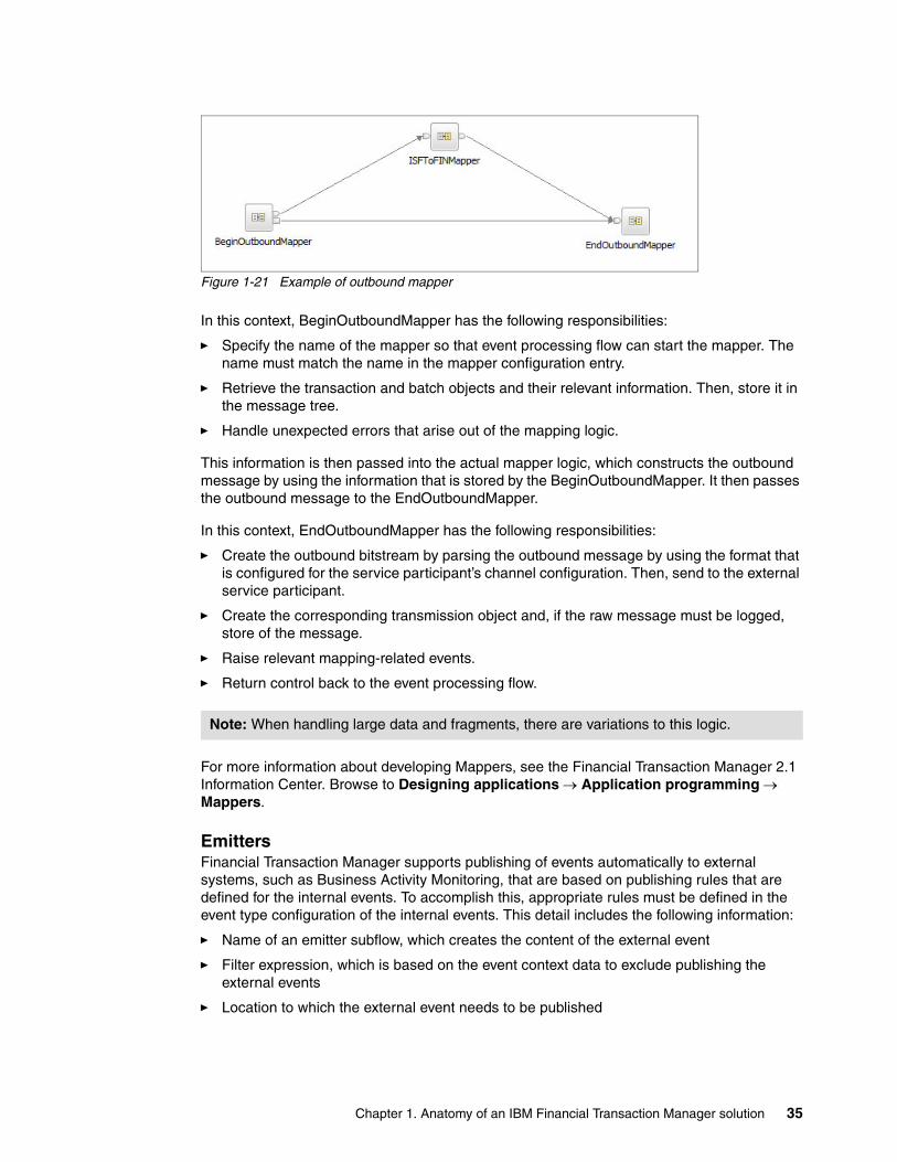
Figure 1-21 Example of outbound mapper
In this context, BeginOutboundMapper has the following responsibilities:
� Specify the name of the mapper so that event processing flow can start the mapper. The name must match the name in the mapper configuration entry.
� Retrieve the transaction and batch objects and their relevant information. Then, store it in the message tree.
� Handle unexpected errors that arise out of the mapping logic.
This information is then passed into the actual mapper logic, which constructs the outbound message by using the information that is stored by the BeginOutboundMapper. It then passes the outbound message to the EndOutboundMapper.
In this context, EndOutboundMapper has the following responsibilities:
� Create the outbound bitstream by parsing the outbound message by using the format that is configured for the service participant’s channel configuration. Then, send to the external service participant.
� Create the corresponding transmission object and, if the raw message must be logged, store of the message.
� Raise relevant mapping-related events.
� Return control back to the event processing flow.
For more information about developing Mappers, see the Financial Transaction Manager 2.1 Information Center. Browse to Designing applications Application programming Mappers.
EmittersFinancial Transaction Manager supports publishing of events automatically to external systems, such as Business Activity Monitoring, that are based on publishing rules that are defined for the internal events. To accomplish this, appropriate rules must be defined in the event type configuration of the internal events. This detail includes the following information:
� Name of an emitter subflow, which creates the content of the external event
� Filter expression, which is based on the event context data to exclude publishing the external events
� Location to which the external event needs to be published
Note: When handling large data and fragments, there are variations to this logic.
Chapter 1. Anatomy of an IBM Financial Transaction Manager solution 35
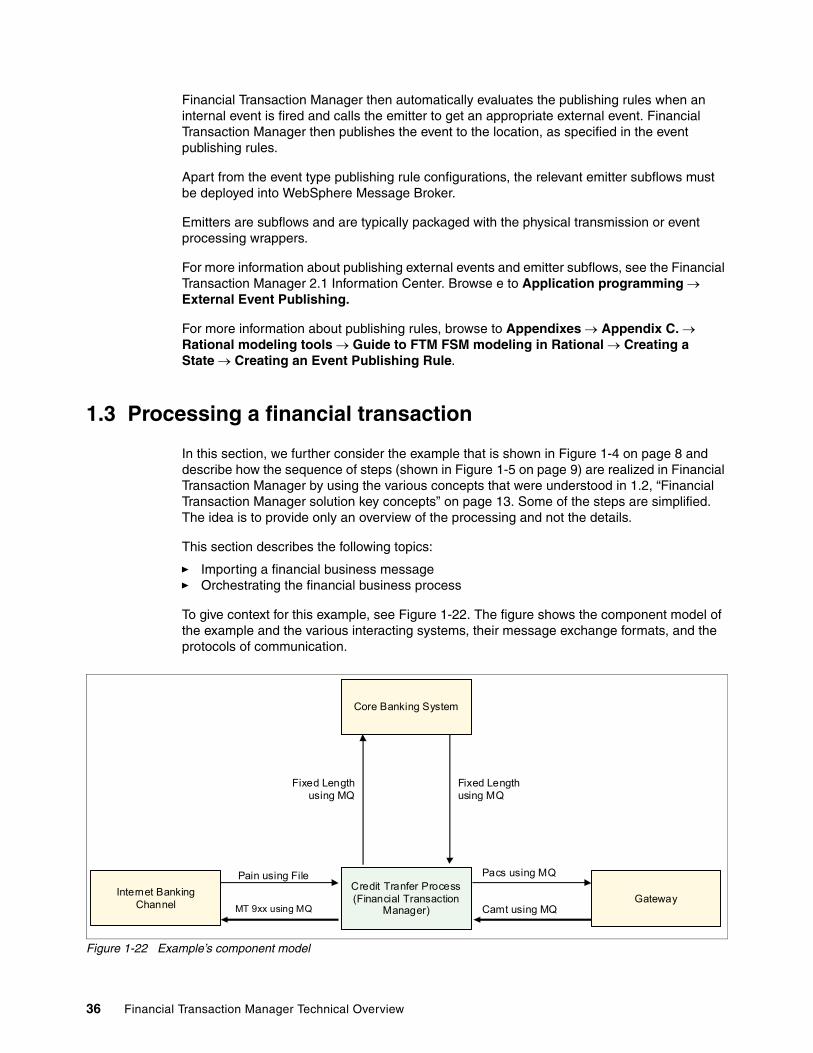
Financial Transaction Manager then automatically evaluates the publishing rules when an internal event is fired and calls the emitter to get an appropriate external event. Financial Transaction Manager then publishes the event to the location, as specified in the event publishing rules.
Apart from the event type publishing rule configurations, the relevant emitter subflows must be deployed into WebSphere Message Broker.
Emitters are subflows and are typically packaged with the physical transmission or event processing wrappers.
For more information about publishing external events and emitter subflows, see the Financial Transaction Manager 2.1 Information Center. Browse e to Application programming External Event Publishing.
For more information about publishing rules, browse to Appendixes Appendix C. Rational modeling tools Guide to FTM FSM modeling in Rational Creating a State Creating an Event Publishing Rule.
1.3 Processing a financial transaction
In this section, we further consider the example that is shown in Figure 1-4 on page 8 and describe how the sequence of steps (shown in Figure 1-5 on page 9) are realized in Financial Transaction Manager by using the various concepts that were understood in 1.2, “Financial Transaction Manager solution key concepts” on page 13. Some of the steps are simplified. The idea is to provide only an overview of the processing and not the details.
This section describes the following topics:
� Importing a financial business message� Orchestrating the financial business process
To give context for this example, see Figure 1-22. The figure shows the component model of the example and the various interacting systems, their message exchange formats, and the protocols of communication.
Figure 1-22 Example’s component model
Core Banking System
Credit Tranfer Process (Financial Transaction
Manager)
Core Banking System
Credit Tranfer Process (Financial Transaction
Manager)Gateway
Internet Banking Channel
Fixed Length using MQ
Fixed Length using MQ
Pacs using MQ
Camt using MQ
Pain using File
MT 9xx using MQ
36 Financial Transaction Manager Technical Overview

For the purpose of this section, it is assumed that all of the interface configurations for the example are created. The following list specifies the various created configurations:
� Credit_Transfer_Service is the Service that provides the credit transfer business process.
� IB_Service_Participant, CB_Service_Participant and GW_Service_Participant are the configured service participants for the three interfacing systems.
� IB_In_Channel, IB_Out_Channel, CB_In_Channel, CB_Out_Channel, GW_In_Channel, and GW_Out_Channel are the various channels of the three interfacing systems.
IB_In_Channel’s master flag is set to true.
� MT_Format, MX_Format and FL_Format are the three formats that are used to transform when interacting with the system.
� Pain_to_ISF, ISF_to_MT, FL_Resp_to_ISF, ISF_to_FL_Req, ISF_to_Pacs and Camt_to_ISF mappers are associated with the respective channels and their names correspond to the deployed mapper subflow artifacts.
The following FSMs are used for processing of the different Transaction and Transmissions and are described in Table 1-2.
Table 1-2 FSMs used for processing
All of the following WebSphere Message Broker artifacts are assumed to be deployed:
� Mappers Pain_to_ISF, ISF_to_MT, FL_Resp_to_ISF, ISF_to_FL_Req, ISF_to_Pacs and Camt_to_ISF
� Message Sets MT_Format, MX_Format and FL_Format
� Actions A_ValidateAndSendToCoreBanking, A_RouteAndSendToGateway and A_SendPaymentReport
� Physical transmission wrapper flow wires the necessary WebSphere Message Broker File Input Node and WebSphere MQ Input Node to the physical transmission core flow. For this example, there are three separate physical transmission wrappers that implement the instances of the physical transmission flow for each of the message sources.
� Event processing wrapper flow wires the necessary WebSphere MQ Output Node representing the event queue WebSphere MQ to the event processing core flow.
Source System Target System Format Mapper Transaction FSM Transmission FSM
Internet Banking Channel
Credit Transfer Process
MX_Format Pain_to_ISF Credit Transfer FSM (see Figure 1-11 on page 19)
Inbound Transmission FSM
Credit Transfer Process
Core Banking System
FL_Format ISF_to_FL_Req Outbound Request FSM
Outbound Transmission FSM
Core Banking System
Credit Transfer Process
FL_Format FL_Resp_to_ISF
Inbound Ack FSM Inbound Transmission FSM
Credit Transfer Process
Gateway MX_Format ISF_to_Pacs Outbound Request FSM
Outbound Transmission FSM
Gateway Credit Transfer Process
MX_Format Camt_to_ISF Inbound Ack FSM Inbound Transmission FSM
Credit Transfer Process
Internet Banking Channel
MT_Format ISF_to_MT Outbound Request FSM
Outbound Transmission FSM
Chapter 1. Anatomy of an IBM Financial Transaction Manager solution 37

1.3.1 Importing a financial business message
The processes that are used to import financial business messages are primarily the responsibility of physical transmission flow.
The following main steps are completed during this phase:
1. Inputting business message into processing2. Creating a transmission object that is related to the message3. Mapping incoming message to ISF4. Creating the associated transaction objects5. Creating the relevant events6. Completing flow
Inputting business message into processingInputting the business message into processing is implemented with an input node on the physical transmission wrapper flow. Various WebSphere Message Broker Input Nodes can be used to take input of business messages for different protocols. Some of the different protocols are WebSphere MQ Input Node, File Input Node, HTTP Input Node, and so on.
For this example, processing (as shown in Figure 1-5 on page 9), the Credit Transfer Request business message in Pain MX format is input through a file interface. Physical transmission wrapper flow uses a WebSphere Message Broker File Input Node to read the input message.
Physical transmission wrapper flow then determines the input channel for the IB_Service_Participant and reads IB_In_Channel. The channel properties determine the format and the mapper to be used (which are MX_Format and Pain_to_ISF, respectively). Physical transmission wrapper then determines what other transmission pertinent information is required for storing the transmission. Other information includes the object unique identifier, customer identifier, and other transport-specific information, such as the file name and file address. Physical transmission wrapper then inputs this information into the core physical transmission flow.
Creating a transmission object that is related to the messageCore physical transmission flow gathers the information that is needed for persisting the transmission object. Most of this data comes from the information that is sent by the wrapper flow. However, it also uses information from the input channel (IB_In_Channel), such as the Master Flag, Party Id, Character Code Set Id, Encoding, and Log Data flag.
Core physical transmission flow then creates a transmission object that is based on the gathered information and persists it in the operational data. This provides a record of the received data and its source for the audit trail. The record also might include an image of the data received, depending on the channel configuration.
Mapping incoming message to ISFCore physical transmission flow then retrieves the mapper and format names (Pain_to_ISF and MX_Format, respectively) from the input channel (IB_In_Channel) and starts the mapper by using the Route To Label WebSphere Message Broker Node.
Cached data: Financial Transaction Manager caches all the configuration data. In the following section, configuration data is mostly fetched from the cache.
38 Financial Transaction Manager Technical Overview

BeginMapper, which helps integrate the mapping logic, is labeled as Pain_to_ISF and starts running. It first parses the input message by using the message set and message type as identified by the MX_Format. It also uses other parsing options (such as character code set and encoding) and whether the parsing is with or without validation from the channel configuration IB_In_Channel.
BeginMapper sends the parsed output to the mapper logic. Mapper logic then constructs the ISF message that is based on the parsed input. The messages in this example consist of a single business transaction.
Mapper logic then gathers other transaction-pertinent information, such as the following information:
� Transaction unique identification
� Transaction customer identification
� Transaction owner identification (Party owning the transaction that can be used for OAC access control)
� Transaction type (Payment)
� Transaction sub type (Credit Transfer Request, which specifies the business purpose of the transaction and controls the FSM selection)
It also extracts payment-specific information (such as payment type, bank code, account, destination bank code, destination account, amount, currency, foreign exchange rate, book date, and value date). This information, along with the ISF and the mapping results (mapping errors, and so on), are then passed to the EndMapper.
EndMapper checks if the ISF must be syntactically validated by reading the input channel configuration IB_In_Channel’s Validate_ISF Flag. If the flag is set, it syntactically validates the ISF message.
Creating the associated transaction objectsEndMapper uses the information and creates the transaction record. EndMapper creates error records for all the mapping errors that are associated with the mapping run and associates them with the created transaction. EndMapper then sets the state of the newly created transaction as S_Mapped and fires the relevant events.
Creating the relevant eventsEvents are created to record the process milestones that were achieved. In this case, the creation of a transaction (E_MpInTxnMapped with the appropriate transaction identification in the context of the event), and the arrival and completion of mapping of the transmission. The new events are written to the event queue to be read by the orchestration step where the events are used to trigger the start of the business process.
EndMapper passes the control back to physical transmission flow.
Completing flowPhysical transmission flow completes and awaits the arrival of the next message.
Note: There is optimization that is related to burst mode processing, which is not described here.
Chapter 1. Anatomy of an IBM Financial Transaction Manager solution 39
1.3.2 Orchestrating the financial business process
Financial business process orchestration is primarily Finite State Machine processing, which is performed by the core event processing flow. It typically consists of the following actions:
� FSM processing� Action invocation� Sending a request to external services� Correlation of response
FSM processingEvent processing wrapper reads the event messages by using WebSphere Message Broker WebSphere MQ Input Node. After the event messages are read from the events queue, the messages are then input to the core event processing flow.
In this example, the first event is the E_MpInTxnMapped event from the completed import. The event processing core flow gets the event type information (for the E_MpInTxnMapped event instance) and reviews the configuration data to find the matching associated transitions. It then evaluates the event filter that is based on the event instance context data and precludes any transition that fails the expression evaluation.
B using the effective of the transition’s FSMs object selection template and the transitions’s override selection and further qualifying by the object filter, core event processing flow obtains a list of all the objects for the transition that must undergo state change. This set of objects includes the transaction object that was created.
Event processing core flow then transitions the state of all the selected objects to the transition’s target state by updating the transaction record.
Core event processing flow then starts the action that is associated with the transition.
Action invocationCore event processing flow then gets the name of the action for the transition, which must be called (in this case, A_ValidateAndSendToCoreBanking). Then, by using Route To Label WebSphere Message Broker Node, core event processing flow starts the action to pass the following information:
� Input Message, which contains the event instance data
� Information about the transition, such as the name of the FSM, the type of the object that is modeled by the FSM, object selection template (or override selection) value, object filter, and event type of the event instance
� Set of transaction objects and their retrieved column data
Depending on the object selection template or override selection, ISF data of the transaction can also be indicated, in which case the ISF data is also available as part of the column data.
BeginAction of the action identifies with the action name as specified in the transition. Action is then started and passes control to the actual action logic. The started action logic can perform any kind of business logic that is based on the transaction data and ISF; for example, semantically validating the transaction and ISF data. After successfully validating the transaction, the action (A_ValidateAndSendToCoreBanking) must send a request to the core banking system.
40 Financial Transaction Manager Technical Overview

Sending a request to external servicesAll legs of the processing are considered as a separate transaction or transmission. Hence, the core banking request must have its own transaction or transmission objects. However, because the request-reply pattern is standard, the Outbound Transaction and Transmission generic FSM is used for these objects.
The action (A_ValidateAndSendToCoreBanking) first creates the ISF message to send to the core banking system. The ISF message to be created is based on the credit transfer request transaction’s ISF data (and possibly with some other enrichment as needed for the core banking request). It then creates a transaction object for the outward request to the core banking system and appropriately sets the attributes (including the initial state [S_OutTxnCreated], type, sub type, and ISF data appropriately). For choosing the outbound transaction FSM, the action sets the OBJ_CLASS field to OUT_TXN_WAIT.
The action then creates an object-to-object causal relationship between the credit transfer request transaction and the outward core banking request transaction. This is done by persisting the object-to-object relationship between the two transactions.
Finally, it raises the E_TxnOutCreated event, which is input into the events queue. This event, in its context, contains the ID of the newly created transaction and can also contain the ID of the service participant for the core banking system, to which the request must be sent. This information is later used to route to the core banking system.
The action (A_ValidateAndSendToCoreBanking) then passes control to EndAction, which returns control back to the event processing flow. After the current set of transition is run, event processing flow checks if the current event instance that is processed must be persisted. If it does, core event processing flow stores the event in the Operational Data. Core event processing flow then loops back to the events queue and picks up the new event for processing.
Event processing flow’s processing of this event causes it to evaluate the outbound transaction FSM, and results in processing of the action A_RouteAndSendOutTxn. This is done after transitioning the state of the outbound transaction to S_OutTxnAwaitingSend. This action is supplied as part of Financial Transaction Manager to support the generic FSM.
A_RouteAndSendOutTxn, looks up the service participant for the core banking system, CB_Service_Participant, which is based on the service participant ID in the event instance’s context data.
It then gathers the outbound channel details (CB_Out_Channel) from which the format (FL_Format) and outbound mapper (ISF_to_FL_Req) information is retrieved for sending requests to the core banking system. A_RouteAndSendOutTxn starts the outbound mapper that corresponds to ISF_to_FL_Req by using the Route To Label WebSphere Message Broker Node.
BeginOutboundMapper identifies the actual mapper (as in the name) and runs the out mapper. It fetches the information that is related to the transaction, including ISF, and makes that available. BeginOutboundMapper then passes the information to the actual outbound mapping logic. The mapping logic constructs the output message (based on the transaction data and ISF) and passes the output message to EndOutboundMapper.
Note: This mechanism is not the only routing mechanism that is supported by Financial Transaction Manager.
Chapter 1. Anatomy of an IBM Financial Transaction Manager solution 41

EndOutboundMapper uses the message set and message type (as specified in the format, FL_Format) and writes the output bytestream to the core banking system. This is done by looking into the WebSphere MQ configuration for the core banking system (WebSphere MQ Queue Manager and WebSphere MQ Queue name) from the configured Channel object (CB_Out_Channel).
EndOutboundMapper then creates the outbound transmission object. If the raw data must be logged, EndOutboundMapper updates it. EndOutboundMapper then raises the relevant events on receipt of the successfully sent events, the outbound transaction transitions to S_WaitingForAck.
Correlation of responseWhen the core banking system’s response arrives, it is handled by the physical transmission flow as any other incoming business message. A set of transmission and transaction objects also are created.
The transaction that is created has OBJ_CLASS set to one of the following values:
� IN_TXN_ACK_MQ1� IN_TXN_ACK_MQ2� IN_TXN_ACK_CID
These values determine the correlation strategy that must be used to correlate the incoming response message to the outgoing request message.
Based on this OBJ_CLASS value, the response transaction is subject to Inbound Acknowledgement Transaction generic FSM. When handling the E_MpInTxnMapped event per inbound acknowledgement transaction generic FSM, event processing flow runs the action A_CorrelateAndUpdateRel.
A_CorrelateAndUpdateRel correlates the incoming acknowledgement to the outgoing request, which is based on the different correlation strategies, and after success, raises E_AckRecvd. A_CorrelateAndUpdateRel also sets up the necessary causal relationship between the response and request transactions.
At receipt of this event, inbound acknowledgement transaction generic FSM responds by transitioning the response transaction to S_InTxnComplete. After this occurs, processing is complete for the transaction.
After receipt of E_AckRecvd event, outbound transaction generic FSM responds by transitioning the request transaction to S_OutTxnComplete. Outbound transaction generic FSM then starts A_RaiseOutTxnCompleteEvents action, which raises events that flag the credit transfer request to continue with the credit transfer FSM (see Figure 1-13 on page 22).
Remaining processing continues based on this FSM. Thus, Financial Transaction Manager completes the processing of the transaction.
42 Financial Transaction Manager Technical Overview

Chapter 2. Design and development methodology overview
This chapter provides a recommended approach to follow when you are designing and developing Financial Transaction Manager solutions. The design and development of a relatively complex Financial Transaction Manager application often is an iterative process. The guidelines that are outlined in this chapter might require some customization that is based on individual project requirements and setup. However, the template that is outlined, which was honed through the use in numerous Financial Transaction Manager projects, should provide assistance to anyone taking the first step in Financial Transaction Manager solution design.
In general, when Financial Transaction Manager is introduced into an environment, it is recommended that a progressive renovation approach is followed, that is, an avoidance of trying to do too much too soon. Tasks should be undertaken in manageable increments, which should lead to reduced risk and early proof of concept, with the overall target being an early return on investment and increased confidence in the solution approach.
This design approach is not meant to replace existing IT leading practices but to enrich them. Structured project management, identification of key roles and skills, the use of proven technologies, configuration management, testing, and so on, should be used with this approach to achieve a successful outcome.
The chapter covers the Financial Transaction Manager methodology and describes how a solution can be designed from a set of Use Cases that describe the business requirements, through to a set of High Level and Detailed Sequence diagrams that show the sequence of interactions and processing steps that are involved with the application. This leads to a set of Lifecycle diagrams that define a set of states for business objects, with the conditions and triggers to move between those states and the activities to perform while doing so. This all leds to a set of Finite State Machines that model the processes and can be imported into the Financial Transaction Manager data model to drive the real-world functionality.
2
© Copyright IBM Corp. 2014. All rights reserved. 43

This chapter includes the following topics:
� Capturing requirements� Architectural decisions� Following the methodology
44 Financial Transaction Manager Technical Overview

2.1 Capturing requirements
Capturing requirements can be facilitated through a series of workshops. The goal of these workshops is to capture solution requirements, produce an architectural overview, build a solution outline, and design a set of functional use cases.
The workshop process often is an iterative one. When the key players are identified (for example, Solution Architect, Financial Transaction Manager Architect, Interface Specialist, and Subject Matter Experts), the workshop process facilitates the meeting of minds, sharing of ideas, and knowledge transfer. It also facilitates the Financial Transaction Manager Architects understanding of the proposed solution, and provides a forum for the Financial Transaction Manager Architect to provide confirmations or propose amendments. The workshop process also allows the business to explore Financial Transaction Manager concepts with the Financial Transaction Manager Architect and to address any outstanding architectural issues.
Use Cases are used as a means to translate business requirements into functional requirements. Figure 2-1 shows a sample Use Case that was designed by using Rational Software Architect.
Figure 2-1 Sample use case
When a high-level use case such as this is created, details of interfaces that are needed for the solution become more apparent. From this, you can design an architecture overview and solution outline. The architecture overview often is represented by a diagram that shows the various high-level architectural components. The solution outline shows the interactions between external systems and Financial Transaction Manager. A High Level Sequence diagram is used to represent these interactions.
Chapter 2. Design and development methodology overview 45

Figure 2-2 shows the High Level Sequence diagram that was created in Rational Software Architect for the Use Case as shown in Chapter 1, “Anatomy of an IBM Financial Transaction Manager solution” on page 1.
Figure 2-2 High Level Sequence diagram
You produce a High Level Sequence diagram for all defined use cases. This type of diagram is an easily understood way to represent Financial Transaction Manager regarding external systems. In addition to outlining interactions over a period, these diagrams offer a method of documenting internal actions that Financial Transaction Manager must take as part of the process. These diagrams also feed into the creation of Detailed Sequence diagrams, as shown in 3.5, “Detailed sequence diagrams” on page 70. Later sections In Chapter 3, “Producing design artifacts by using Rational Software Architect” on page 57 we describe how you can expand these diagrams to define a set of Lifecycle diagrams, and, ultimately, a set of Finite State Machines, to model the processes. For information about how to physically create these diagrams and models, see Chapter 3, “Producing design artifacts by using Rational Software Architect” on page 57.
By using the High Level Sequence diagram as a guide, you can begin a discussion to identify and document interface and message types, and use details about protocols that are used (for example, WebSphere MQ, SOAP, and FILE), formats that are required (for example, ACH, SWIFT, and EDI), and message types that are needed (for example, EDI820, MT103, and PACS008).
Finally, you can discuss and document a set of non-functional requirements from the workshops. You can cover topics, such as availability, disaster-recovery, performance, and latency at this stage.
46 Financial Transaction Manager Technical Overview

2.2 Architectural decisions
From an early stage, it is important to think about key architectural strategies and decisions that affect the current and future projects. It is imperative to keep the long-term strategic vision and requirements in mind now because although decisions made at this stage might suit the current iteration of the project, they might not meet the requirements of the overall solution.
The Solution Architect can, with input from the Financial Transaction Manager Architect, Interface Specialists, along with the Business Stakeholders, explore avenues of discussion that pertain to hardware configuration, the Financial Transaction Manager environment, user security, database architecture, and so on.
Non-functional requirements have a large bearing on some of the architectural decisions. For example, requirements around High Availability, Scalability, and Performance can lead to a decision to go with a multi-instance topology, running more than one Financial Transaction Manager instance on one or more logical partitions, by way of data sharing.
In terms of hardware configuration, decisions on a range of topics, such as the platform to use (if not already dictated), the type and size of storage that is used, the number of CPUs that are needed to handle the software stack and the throughput, and the number and size of logical partitions all must be made.
Financial Transaction Manager dictates a set of software prerequisites for it to run. These should be discussed and decisions made on levels of software that is needed to integrate with Financial Transaction Manager; for example, if integration with WebSphere Transformation Extender and IBM Operational Decision Manager is needed.
Decisions can be made on the level of security that is necessary for users of the solution. The number and type of interfaces can have a large bearing on these decisions. For example, if customer on-boarding is part of the solution, some thought needs to go in to how to allow external sources access only the parts of the application that are pertinent to them.
2.3 Following the methodology
The Financial Transaction Manager Methodology is a step-by-step guide to help solution architects and developers design and develop a Financial Transaction Manager solution. The methodology was born out of numerous Financial Transaction Manager customer engagements and was proven to be an effective guide to assist with the creation of a solution.
The Financial Transaction Manager Information Centers already covers the Methodology in detail, but in this section, we describe the steps that are involved and provide more guidance where possible (or at least try to provide a fresh perspective to the steps).
Chapter 2. Design and development methodology overview 47

Figure 2-3 shows the design, development, and miscellaneous tasks that are involved in a Financial Transaction Manager solution.
Figure 2-3 Financial Transaction Manager design and coding tasks
2.3.1 Design tasks
The following sections provide details about the methodology concerning the design tasks.
Define High Level Sequence diagramsHigh Level Sequence diagrams show the interaction between the external systems and Financial Transaction Manager. These diagrams also show the sequence of high-level processing tasks, such as “Map To ISF,” “Complete Routing Decision,” and “Log Physical Transmission,” that happen internally in Financial Transaction Manager.
Define a set of these diagrams to cover all use cases, including positive and negative cases. For more information about how to create these diagrams, see Chapter 3, “Producing design artifacts by using Rational Software Architect” on page 57. High Level Sequence diagrams are expanded to create Detailed Sequence diagrams. Therefore, try to keep a separation and keep the diagrams at a high-level.
Identify Interfaces and Message Types
Create Mapping Specifications
Create Message Models for Formats
Code Mapper Subflows/WTX Maps
Model Configuration Data
Define High Level Sequence Diagrams
Identify FTM Objects & Design Detailed
Sequence Diagrams
Design Object Lifecycle Diagrams
Build FSM Model
Code Action Subflows/Emitter Subflows/ODM Business Rules
Build FTM Environment (MQ, DB2, WMB, WAS)
Code Top Level Flows (Integrate Mappers, Actions with FTM
Framework)
Extract and Deploy FSM Model to FTM
Database
Extract and Deploy Configuration Data to FTM Database
Deploy FTM Application Flows
Coding Task
Design Task
Misc. Task
Interfaces Processes Deployment
Remember: High Level Sequence diagrams are specific to individual customer solutions and environments. The Solution Architect and the Financial Transaction Manager Architect often are involved in creating these diagrams.
48 Financial Transaction Manager Technical Overview
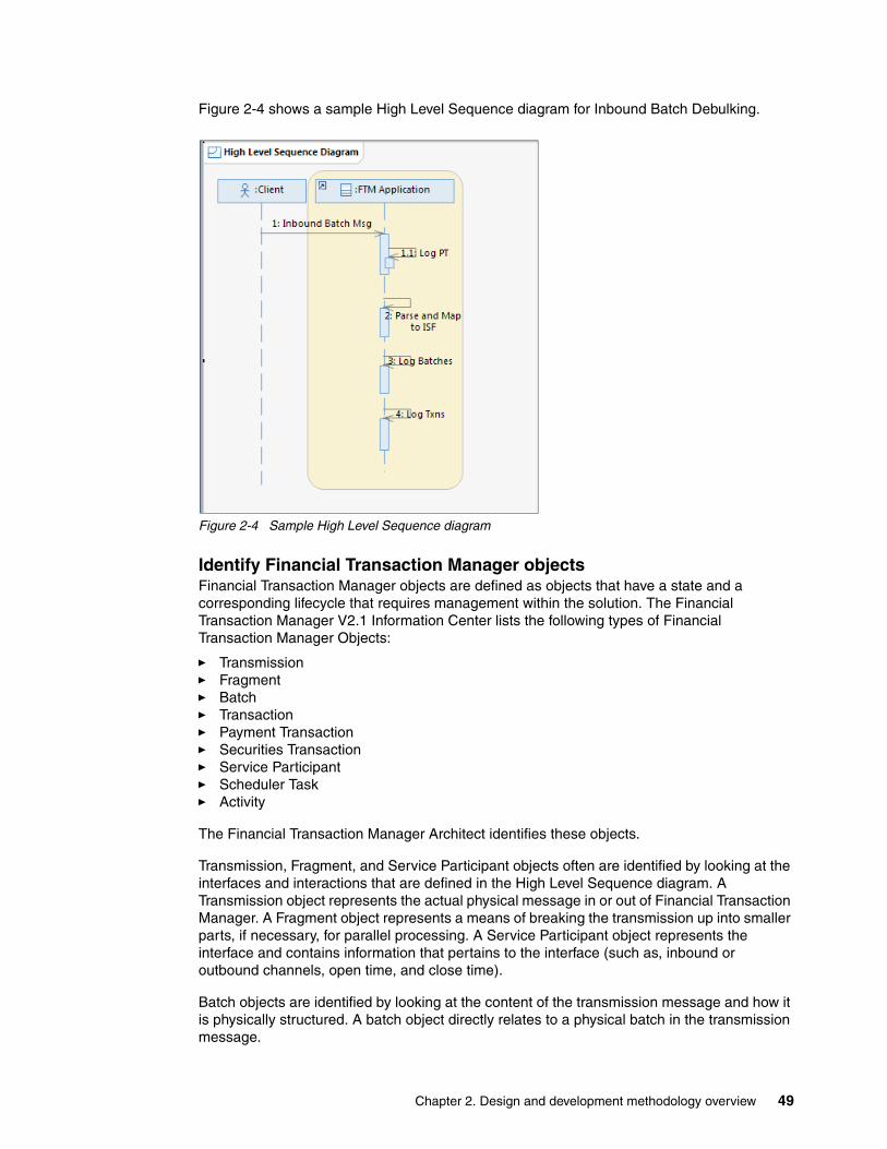
Figure 2-4 shows a sample High Level Sequence diagram for Inbound Batch Debulking.
Figure 2-4 Sample High Level Sequence diagram
Identify Financial Transaction Manager objectsFinancial Transaction Manager objects are defined as objects that have a state and a corresponding lifecycle that requires management within the solution. The Financial Transaction Manager V2.1 Information Center lists the following types of Financial Transaction Manager Objects:
� Transmission� Fragment� Batch� Transaction� Payment Transaction� Securities Transaction� Service Participant� Scheduler Task� Activity
The Financial Transaction Manager Architect identifies these objects.
Transmission, Fragment, and Service Participant objects often are identified by looking at the interfaces and interactions that are defined in the High Level Sequence diagram. A Transmission object represents the actual physical message in or out of Financial Transaction Manager. A Fragment object represents a means of breaking the transmission up into smaller parts, if necessary, for parallel processing. A Service Participant object represents the interface and contains information that pertains to the interface (such as, inbound or outbound channels, open time, and close time).
Batch objects are identified by looking at the content of the transmission message and how it is physically structured. A batch object directly relates to a physical batch in the transmission message.
Chapter 2. Design and development methodology overview 49
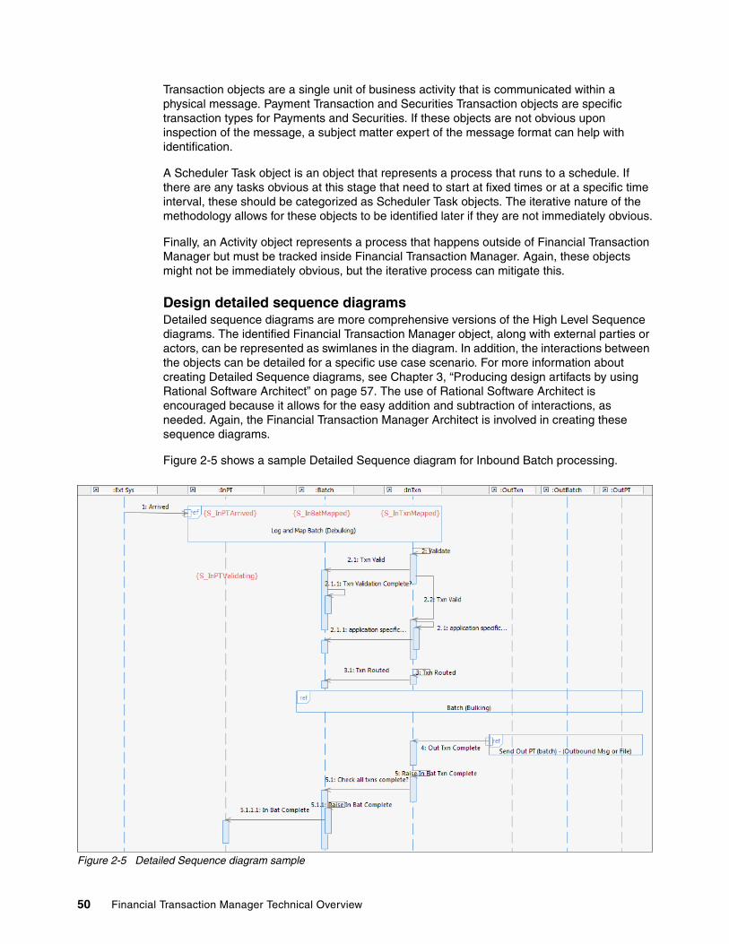
Transaction objects are a single unit of business activity that is communicated within a physical message. Payment Transaction and Securities Transaction objects are specific transaction types for Payments and Securities. If these objects are not obvious upon inspection of the message, a subject matter expert of the message format can help with identification.
A Scheduler Task object is an object that represents a process that runs to a schedule. If there are any tasks obvious at this stage that need to start at fixed times or at a specific time interval, these should be categorized as Scheduler Task objects. The iterative nature of the methodology allows for these objects to be identified later if they are not immediately obvious.
Finally, an Activity object represents a process that happens outside of Financial Transaction Manager but must be tracked inside Financial Transaction Manager. Again, these objects might not be immediately obvious, but the iterative process can mitigate this.
Design detailed sequence diagramsDetailed sequence diagrams are more comprehensive versions of the High Level Sequence diagrams. The identified Financial Transaction Manager object, along with external parties or actors, can be represented as swimlanes in the diagram. In addition, the interactions between the objects can be detailed for a specific use case scenario. For more information about creating Detailed Sequence diagrams, see Chapter 3, “Producing design artifacts by using Rational Software Architect” on page 57. The use of Rational Software Architect is encouraged because it allows for the easy addition and subtraction of interactions, as needed. Again, the Financial Transaction Manager Architect is involved in creating these sequence diagrams.
Figure 2-5 shows a sample Detailed Sequence diagram for Inbound Batch processing.
Figure 2-5 Detailed Sequence diagram sample
50 Financial Transaction Manager Technical Overview

Design object lifecycle diagramsExamination of the Financial Transaction Manager object swimlanes that was created in the Detailed Sequence diagram provides the basis for the Object Lifecycle diagrams. Starting from the top and working down for each swimlane highlights the various states that the object goes through and the high-level events that cause the object to move from one state to another. If there are multiple Detailed Sequence diagrams for the same object (for example, in the case of showing error conditions), these states and transitions are shown also on the Lifecycle diagram for the object in question.
Figure 2-6 shows a sample Object Lifecycle diagram for Outbound Physical Transmissions.
Figure 2-6 Sample Object Lifecycle diagram
Build Finite State Machine modelThe “Application analysis and design tutorial” section of the “Designing Applications” chapter of the Financial Transaction Manager V2.1 Information Center provide details about building a Finite State Machine model that consists of a set of Finite State Machines from the previously described diagrams.
A Finite State Machine is derived from an Object Lifecycle diagram because they both describe the behavior of a Financial Transaction Manager object. Financial Transaction Manager provides a Rational Software Architect plug-in as part of its core components. This plug-in provides more UML extensions in the form of stereotypes and facilitates the extraction of the Finite State Machine into an SQL script that can be run against a Financial Transaction Manager database.
Chapter 2. Design and development methodology overview 51
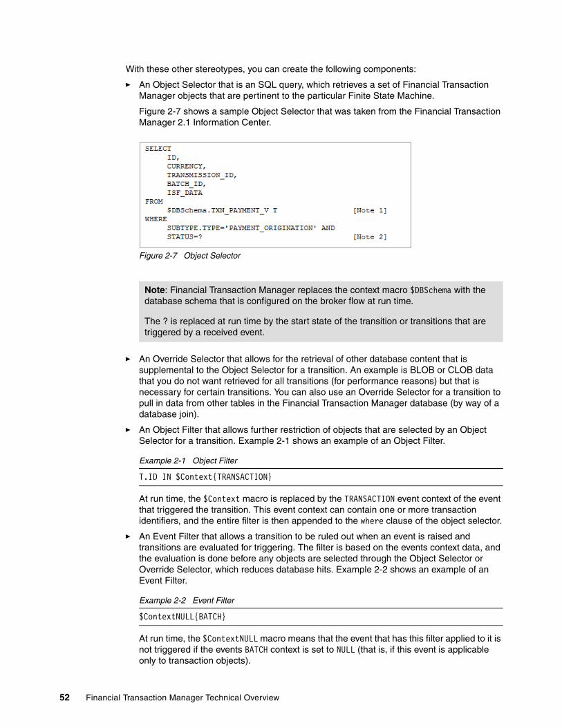
With these other stereotypes, you can create the following components:
� An Object Selector that is an SQL query, which retrieves a set of Financial Transaction Manager objects that are pertinent to the particular Finite State Machine.
Figure 2-7 shows a sample Object Selector that was taken from the Financial Transaction Manager 2.1 Information Center.
Figure 2-7 Object Selector
� An Override Selector that allows for the retrieval of other database content that is supplemental to the Object Selector for a transition. An example is BLOB or CLOB data that you do not want retrieved for all transitions (for performance reasons) but that is necessary for certain transitions. You can also use an Override Selector for a transition to pull in data from other tables in the Financial Transaction Manager database (by way of a database join).
� An Object Filter that allows further restriction of objects that are selected by an Object Selector for a transition. Example 2-1 shows an example of an Object Filter.
Example 2-1 Object Filter
T.ID IN $Context{TRANSACTION}
At run time, the $Context macro is replaced by the TRANSACTION event context of the event that triggered the transition. This event context can contain one or more transaction identifiers, and the entire filter is then appended to the where clause of the object selector.
� An Event Filter that allows a transition to be ruled out when an event is raised and transitions are evaluated for triggering. The filter is based on the events context data, and the evaluation is done before any objects are selected through the Object Selector or Override Selector, which reduces database hits. Example 2-2 shows an example of an Event Filter.
Example 2-2 Event Filter
$ContextNULL{BATCH}
At run time, the $ContextNULL macro means that the event that has this filter applied to it is not triggered if the events BATCH context is set to NULL (that is, if this event is applicable only to transaction objects).
Note: Financial Transaction Manager replaces the context macro $DBSchema with the database schema that is configured on the broker flow at run time.
The ? is replaced at run time by the start state of the transition or transitions that are triggered by a received event.
52 Financial Transaction Manager Technical Overview

After the Object States and Transitions are worked out, along with the events that trigger the transitions, any actions that are necessary to be called between transitions can be added. These actions are added as UML activities to the transitions. Document any pseudocode for these actions in the model because this pseudocode is used when the actions are coded later in the development process.
Figure 2-8 shows a sample Finite State Machine for Inbound Acknowledgement Transactions.
Figure 2-8 Sample Finite State Machine diagram
Important: Finite State Machines interact with each other. To model the process of a message through Financial Transaction Manager involves the use of multiple Finite State Machines that handle the orchestration of the various objects that are created as part of the process, be it Transmissions, Batches, Transactions, and so on. The Financial Transaction Manager Architect identifies these objects and creates (or is closely involved in creating) the Finite State Machines.
Chapter 2. Design and development methodology overview 53
Model configuration dataThe Rational Software Architect plug-in that is provided with Financial Transaction Manager also allows for the extraction of configuration data that is modeled by using UML in Rational Software Architect. Configuration data, such as channel data, mapper data, formats, scheduler task data, and value table data, can all be modeled and extracted. For more information about how to create these structures, see the “Guide to Configuration Data Modeling” section in “Appendix C. Rational Modeling tools” of the Financial Transaction Manager V2.1 Information Center.
Identify interface and message typesIdentifying interface and message types is a task that can be carried out though one of the workshop iterations. Sometimes, a simple rough diagram can facilitate the identification of interactions with Financial Transaction Manager and when identified, details about the communication protocols, message formats, and message types can be hashed out. Each interaction is represented by an interface, and with help from interface specialists, each protocol, format, and message type should be identified and documented. Be as specific as possible at this stage and include details, such as copybooks or XML schema that are used for formats or versions of message standards used. The Solution Architect, Financial Transaction Manager Architect, and Interface Specialists should be involved in this activity.
Create mapping specificationsFor each of the interfaces that are identified, create a mapping specification document for each message type, and map each field in the interfaces format to a field in the internal standard format (ISF), for interfaces that are inbound to Financial Transaction Manager, and from a field in the ISF to a field in the interfaces format, for interfaces outbound from Financial Transaction Manager. The mapping specification usually is created as a spreadsheet with a sheet that details the fields in the external format, a sheet that details the fields in the ISF, and a sheet that details the mapping between them.
Business Analysts, Interface Specialists, and the Financial Transaction Manager Architect all provide input into the creation of this document. For more information, see Chapter 4, “Mapping” on page 85.
2.3.2 Development and coding tasks
In this section, we describe following the methodology regarding development and coding tasks. The Financial Transaction Manager Developers is responsible for these tasks, with input from the Financial Transaction Manager Architect, when needed. Experience in WebSphere Message Broker is recommended for developers or experience in whatever mapping technology is chosen for developing the mappers.
Create message models for formatsDepending on the software technology that is used for message transformation, usually some sort of metadata model must be created that maps the structure of the format of the message. For example, if native WebSphere Message Broker is used to handle your transformations, you might need to create message sets or import XML schema. If WebSphere Transformation Extender is used, you might need to create Type Trees to model the format.
Note: After the mapping specifications are complete and signed off, they can be given to developers to start work on implementing the mappers in parallel to the remainder of the design process.
54 Financial Transaction Manager Technical Overview
Code mapper subflows and WebSphere Transformation Extender mapsCoding the mappers can be carried out in parallel to the design tasks that were described in 2.3.1, “Design tasks” on page 48 after the mapping specifications are complete. Inbound and Outbound Mapper Templates are included as part of the Templates package that is supplied with Financial Transaction Manager. These templates are skeleton WebSphere Message Broker message flows that contain the nodes and links that are necessary for a mapper subflow and an ESQL template that provides the basic structure, including functions to call to create an inbound or outbound mapper. For more information, see “Appendix I. Templates” in the Financial Transaction Manager V2.1 Information Center.
If you are using WebSphere Transformation Extender to develop the maps, use the WebSphere Transformation Extender Integration flows to integrate the maps with Financial Transaction Manager. For more information about WebSphere Transformation Extender integration, see “WebSphere Transformation Extender Mappers” in the “Application Programming” section of the Financial Transaction Manager V2.1 Information Center.
Code action subflows, emitter subflows, and IBM Operational Decision Manager Business RulesAs with the mapper subflows, templates are available to help with coding the action subflows and the emitter subflows. These templates, along with the Finite State Machine pseudocode created during the design stage, can make it relatively straightforward to code the actions.
Code top level flowsWrapper flows are needed to link to the Financial Transaction Manager core Physical Transmission and Event Processing flows. Templates are provided for these flows in the Financial Transaction Manager package. Some thought must go into the number and content of the Physical Transmission Wrapper flows. Depending on the amount of traffic for a channel, it is often useful to give a channel with particularly heavy traffic its own Physical Transmission Wrapper. This method facilitates the ability to deploy the Wrapper flow to its own WebSphere Message Broker execution group, which allows for better resource assignment flexibility.
2.3.3 Miscellaneous tasks
In addition to the Design and Coding tasks, you must complete some miscellaneous tasks to get a successful Financial Transaction Manager application up and running.
Build the Financial Transaction Manager environmentStemming from the design stage, decisions about hardware and hardware configurations were made. These decisions must be put into action, and tasks (such as configuring the hardware, installing the software stack to support Financial Transaction Manager, and configuring said stack) must be undertaken. For example, you must create the Financial Transaction Manager database, and create and configure WebSphere MQ queues that are used. For more information, see the “Installing” section in the Financial Transaction Manager V2.1 Information Center.
Important: Actions can affect more than one object at a time, and so must be coded so. If integration with IBM Operational Decision Manager is required, code any Business Rules that are needed. An IBM Operational Decision Manager Rule designer is assigned this task.
Chapter 2. Design and development methodology overview 55

DeploymentTo get the Financial Transaction Manager application up and running, you must run the Finite State Machine and Configuration data scripts that were extracted by using the Rational Software Architect plug-in against the Financial Transaction Manager database. You also must create and deploy the WebSphere Message Broker BAR files to the running WebSphere Message Broker. Finally, you must install the Operations and Administration Console. For more information, see the “Installing” section of the Financial Transaction Manager V2.1 Information Center.
2.3.4 Testing
When a Financial Transaction Manager solution is tested, follow a leading practice; for example, record results, manage environments, and use meaningful test data. Draw up test plans for integration, functional, and stress and performance testing, with test cases that use the normal and failure use cases that are designed earlier in the process to provide full test coverage. Use testing for reporting, tracking, and managing defects and issues, which can facilitate resolution and retest and lead to an increase in execution maturity. Testing usually requires a number of test phases, especially for larger solutions.
56 Financial Transaction Manager Technical Overview

Chapter 3. Producing design artifacts by using Rational Software Architect
In this chapter, we describe a suggested approach for the use of Rational Software Architect when a Financial Transaction Manager pattern or application is designed.
We describe, with examples, the various steps that are involved in creating the design artifacts that are used in Financial Transaction Manager. The scope of the chapter covers the design of a sample pattern, but the same concepts and design levels can be used when a full application is designed.
This chapter includes the following topics:
� Design levels� Model project structure� Functional use case diagrams� High-level sequence diagrams� Detailed sequence diagrams� Object lifecycle diagrams� Object relationship diagrams� Finite State Machines
3
Note: This chapter is not meant to describe a rigid set of instructions about how to use Rational Software Architect for Financial Transaction Manager design. Instead, it is meant to complement existing established design structures that you might have in place.
It also is not meant to be a tutorial on Unified Modeling Language, although Unified Modeling Language is used throughout the design.
For this chapter, Rational Software Architect Version 8 is used.
© Copyright IBM Corp. 2014. All rights reserved. 57

3.1 Design levels
The following suggested design levels are used during Financial Transaction Manager Analysis and Design:
� Functional use case diagrams� High-level sequence diagrams� Detailed sequence diagrams� Object lifecycle diagrams� Finite state machine diagrams� Object to object relationship diagrams
A Financial Transaction Manager application is driven by a set of Finite State Machine diagrams. The diagrams that are listed here should all help with the creation of the Finite State Machines, but are not integral to their creation. With experience, a Finite State Machine can be created from scratch, but the suggested approach can provide some aid to their creation.
3.2 Model project structure
When a model project is created, consider the structure of the components within the project. For example, the structure of packages can show the steps that are involved in the design process for Financial Transaction Manager.
58 Financial Transaction Manager Technical Overview
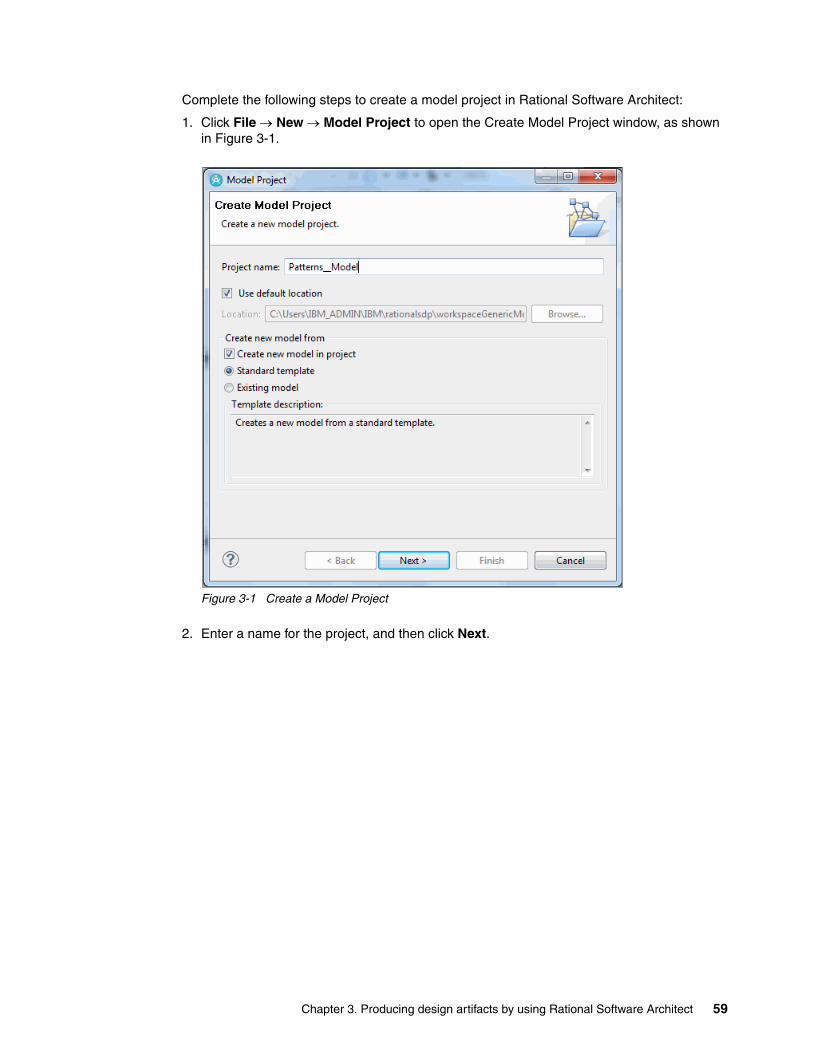
Complete the following steps to create a model project in Rational Software Architect:
1. Click File New Model Project to open the Create Model Project window, as shown in Figure 3-1.
Figure 3-1 Create a Model Project
2. Enter a name for the project, and then click Next.
Chapter 3. Producing design artifacts by using Rational Software Architect 59

3. Select the Blank Design Package template, and enter the file name, as shown in Figure 3-2. Click Next.
Figure 3-2 Listing of available Model Project Templates
4. Select Model and click Finish.
5. Click the model, and in the Properties tab, ensure that the Capabilities match those that are shown in Figure 3-3.
Figure 3-3 Model Capabilities
60 Financial Transaction Manager Technical Overview

6. Right-click the model (not the model project), and click Add UML Package. Add packages as needed. Figure 3-4 shows a suggested package naming convention.
Figure 3-4 Model Packages in a Rational Software Architect model
By numbering your package names, you can ensure that they appear in the correct order in the model.
7. You can also import packages from outside the model on which you are working. For example, a package that is called Common Pattern Entities that includes components that are used by all pattern models is used in Chapter 9, “Patterns” on page 237. To include an external package such as this package, click the Advanced tab in the Properties panel, and then click the button that is beside the PackageImport field, as shown in Figure 3-5.
Figure 3-5 Advanced Properties PackageImport
Chapter 3. Producing design artifacts by using Rational Software Architect 61

8. The PackageImport Properties pane opens. Click the Insert New Package Import button, as shown in Figure 3-6.
Figure 3-6 PackageImport Properties
You can then browse any models in the workspace to select the package that you want to include. Figure 3-7 shows the Common Patterns Entities package in the Patterns_Common model.
Figure 3-7 Common Patterns Entities package import
62 Financial Transaction Manager Technical Overview

Figure 3-8 shows the final package structure for the patterns model, including package includes.
Figure 3-8 Patterns model package structure
3.3 Functional use case diagrams
Complete the following steps to create a functional use case diagram:
1. Right-click the Functional Use Case Diagrams package and then select Add Diagram Use Case Diagram.
2. Give the use case diagram a name. Figure 3-9 shows the components that are created when a use case diagram is added to a package.
Figure 3-9 Use case diagram in the Functional Use Case Diagrams package
Chapter 3. Producing design artifacts by using Rational Software Architect 63

3. Drag Actors, Use Case entities, and Directed Associations from the palette to the use case diagram. Figure 3-10 shows an example of a simple use case diagram.
Figure 3-10 Actors, a Use Case entity, and Directed Associations
The Project Explorer view shows the individual Unified Modeling Language entities in the Use Case package. For ease of reuse, items that are likely to be reused can be moved to their own package within the Application Entities package.
Figure 3-11 shows the Unified Modeling Language Actors as they are created in the Functional Use Case Diagrams package.
Figure 3-11 Unified Modeling Language Actor entities
64 Financial Transaction Manager Technical Overview
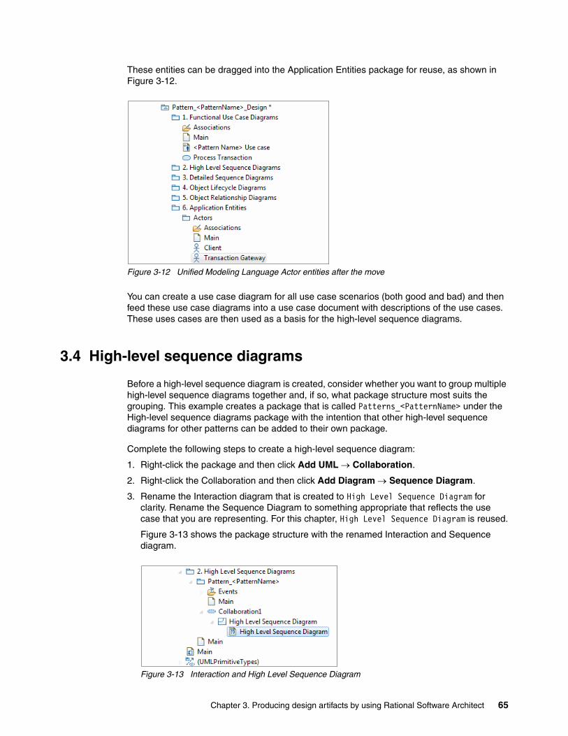
These entities can be dragged into the Application Entities package for reuse, as shown in Figure 3-12.
Figure 3-12 Unified Modeling Language Actor entities after the move
You can create a use case diagram for all use case scenarios (both good and bad) and then feed these use case diagrams into a use case document with descriptions of the use cases. These uses cases are then used as a basis for the high-level sequence diagrams.
3.4 High-level sequence diagrams
Before a high-level sequence diagram is created, consider whether you want to group multiple high-level sequence diagrams together and, if so, what package structure most suits the grouping. This example creates a package that is called Patterns_<PatternName> under the High-level sequence diagrams package with the intention that other high-level sequence diagrams for other patterns can be added to their own package.
Complete the following steps to create a high-level sequence diagram:
1. Right-click the package and then click Add UML Collaboration.
2. Right-click the Collaboration and then click Add Diagram Sequence Diagram.
3. Rename the Interaction diagram that is created to High Level Sequence Diagram for clarity. Rename the Sequence Diagram to something appropriate that reflects the use case that you are representing. For this chapter, High Level Sequence Diagram is reused.
Figure 3-13 shows the package structure with the renamed Interaction and Sequence diagram.
Figure 3-13 Interaction and High Level Sequence Diagram
Chapter 3. Producing design artifacts by using Rational Software Architect 65

Next, you must add the Lifeline swimlanes for each Actor in the Use Case that you want to represent and one for Financial Transaction Manager.
4. Double-click the Sequence diagram to open it. Then, drag a Lifeline from the palette to the diagram.
5. Click the Select Existing Type option. Then, browse to the Actor in the Application Entities package, and click OK. Figure 3-14 shows the Select Element pane that is used when the Actor is selected.
Figure 3-14 Selecting an Actor to represent a Type for the Lifeline
You can make the types in the Lifeline more readable by deleting the representation that is highlighted when the Lifeline is added. Clicking the delete button as this representation is highlighted (usually a lowercase version of the Actor name) clears it and leaves the Type name (in this case the Actor name).
6. Drag a Lifeline to represent Financial Transaction Manager. Then, create the Lifeline as an Unspecified LifeLine.
7. Click the Type button in the Properties pane, and browse to the FTM Application component in the Components package of the common entities model. The model in this example is the Patterns_Common model. Figure 3-15 on page 67 shows the Select Element pane when the FTM Application component is selected.
66 Financial Transaction Manager Technical Overview

Figure 3-15 Selecting a Component to represent a Type for the Lifeline
8. To emphasize the Lifeline as the Financial Transaction Manager Lifeline and to highlight the primary flow of the design, you can drag a rounded rectangle from the Geometric Shapes palette over the FTM Application Lifeline. When placed, clear the highlighted text field because this field is not needed.
9. The rounded rectangle can be sent behind the Lifeline image in the diagram by selecting Diagram Order Send to Back.
This step is optional and is meant only to improve the readability of the high-level sequence diagram.
Chapter 3. Producing design artifacts by using Rational Software Architect 67

Figure 3-16 shows the Client and FTM Application lifelines in the diagram.
Figure 3-16 Client and FTM Application lifelines
10.Drag the remaining lifelines to the diagram and select the associated types (that is, for this example, Transaction Gateway). Figure 3-17 shows all the lifelines that are used by this example.
Figure 3-17 High-level sequence diagram with all the lifelines added
11.At a high level, you must represent the message flow throughout the process from the Sequence palette. For this example, complete the following steps:
a. Click the Asychronous Call Message icon.
b. Click from where the initiator (Client) Lifeline that you want to start and drag to the FTM Application Lifeline.
c. Enter an appropriate name for the Asynchronous Call Message to represent the type of message. For this example, the name is left vague purposely (Inbound Txn Msg).
68 Financial Transaction Manager Technical Overview

Figure 3-18 shows the diagram after the Asynchronous Call Message is added.
Figure 3-18 Lifelines with an Asychronous Call Message included
12.Add any high-level asynchronous call messages that are needed, including calls to the external end-points. For internal calls within Financial Transaction Manager, you do not need to drag the asynchronous call message. Click where on the FTM Application Lifeline the call is being made, and the message routes back to the FTM Application Lifeline. Add as many calls or signal messages that are needed to the diagram.
Chapter 3. Producing design artifacts by using Rational Software Architect 69

Figure 3-19 shows the completed High Level Sequence diagram that is created for this example, including internal Asynchronous Call Message (Validate and Send).
Figure 3-19 A completed High Level Sequence diagram
3.5 Detailed sequence diagrams
Detailed sequence diagrams represent the detailed flow and logic of an object through Financial Transaction Manager. Creating detailed sequence diagrams is an iterative process. In some circumstances, commonly reusable processes are easily recognized. In these cases, the diagrams should be added to the common model. Other times, it is only after a number of iterations through the creation of the Detailed Sequence diagrams that common processes become apparent, and those processes can then be moved to the common model for reuse in other Detailed Sequence diagrams.
It is also useful to create a package structure in your common model to hold any common components that can be reused.
70 Financial Transaction Manager Technical Overview

Figure 3-20 shows an example of this approach for the Patterns_Common model.
Figure 3-20 Package structure of the Patterns_Common model
An example of a common Detailed Sequence diagram that might be reused by other Detailed Sequence diagrams is one modeling the logging and mapping of an Inbound Physical Transmission.
Chapter 3. Producing design artifacts by using Rational Software Architect 71
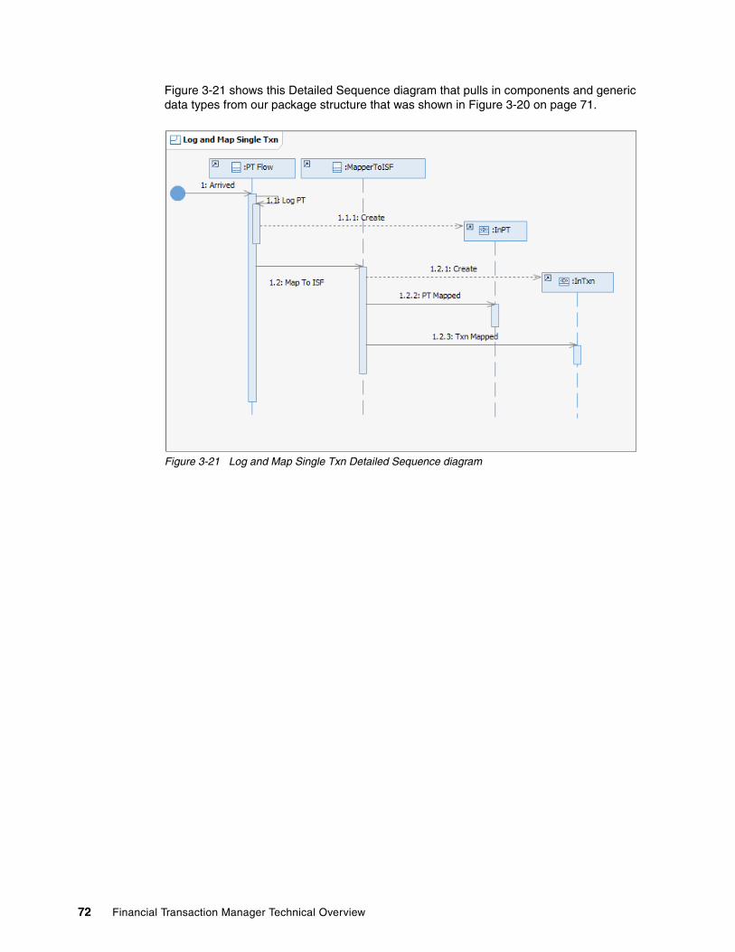
Figure 3-21 shows this Detailed Sequence diagram that pulls in components and generic data types from our package structure that was shown in Figure 3-20 on page 71.
Figure 3-21 Log and Map Single Txn Detailed Sequence diagram
72 Financial Transaction Manager Technical Overview

Figure 3-22 shows another commonly used Detailed Sequence diagram, in which an outbound transaction is routed and the outbound transmission is created and sent to an external system without expecting a reply.
Figure 3-22 Send Txn (Fire and Forget) Detailed Sequence diagram
By building up a repository of these reusable diagrams, you can expedite the creation of larger, more complex detailed sequence diagrams by referencing reusable components. For more information, see Appendix E. Generic Model section of the Financial Transaction Manager V2.1 Information Center.
Chapter 3. Producing design artifacts by using Rational Software Architect 73
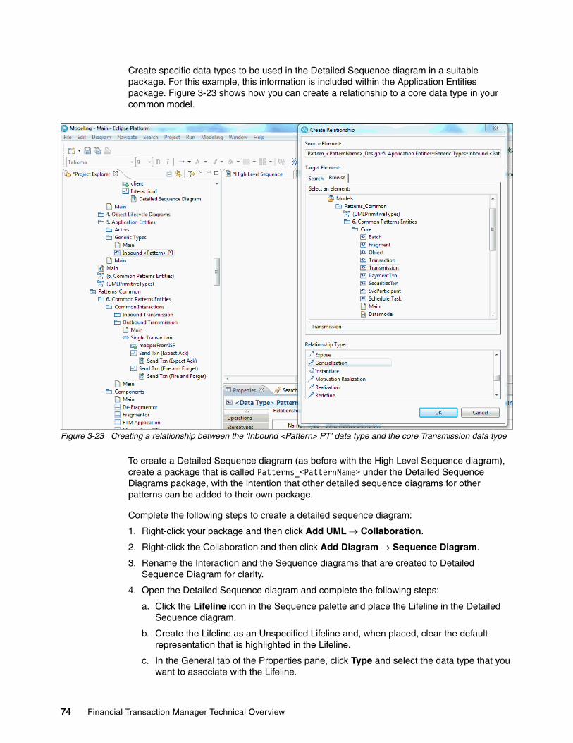
Create specific data types to be used in the Detailed Sequence diagram in a suitable package. For this example, this information is included within the Application Entities package. Figure 3-23 shows how you can create a relationship to a core data type in your common model.
Figure 3-23 Creating a relationship between the ‘Inbound <Pattern> PT’ data type and the core Transmission data type
To create a Detailed Sequence diagram (as before with the High Level Sequence diagram), create a package that is called Patterns_<PatternName> under the Detailed Sequence Diagrams package, with the intention that other detailed sequence diagrams for other patterns can be added to their own package.
Complete the following steps to create a detailed sequence diagram:
1. Right-click your package and then click Add UML Collaboration.
2. Right-click the Collaboration and then click Add Diagram Sequence Diagram.
3. Rename the Interaction and the Sequence diagrams that are created to Detailed Sequence Diagram for clarity.
4. Open the Detailed Sequence diagram and complete the following steps:
a. Click the Lifeline icon in the Sequence palette and place the Lifeline in the Detailed Sequence diagram.
b. Create the Lifeline as an Unspecified Lifeline and, when placed, clear the default representation that is highlighted in the Lifeline.
c. In the General tab of the Properties pane, click Type and select the data type that you want to associate with the Lifeline.
74 Financial Transaction Manager Technical Overview

Figure 3-24 shows the package structure and data types that are used in this example.
Figure 3-24 Selecting a data type to use for a Detailed Sequence diagram Lifeline
If the Lifeline corresponds to a known, pre-existing Finite State Machine model (for example, one of the Generic Finite State Machine models that accompany Financial Transaction Manager), you can complete the following steps to add a stereotype to the Lifeline to reflect this:
1. Click the Stereotypes tab of the Properties pane.
2. In the Keywords field, add the name of the Finite State Machine model that handles the Lifelines process.
Chapter 3. Producing design artifacts by using Rational Software Architect 75
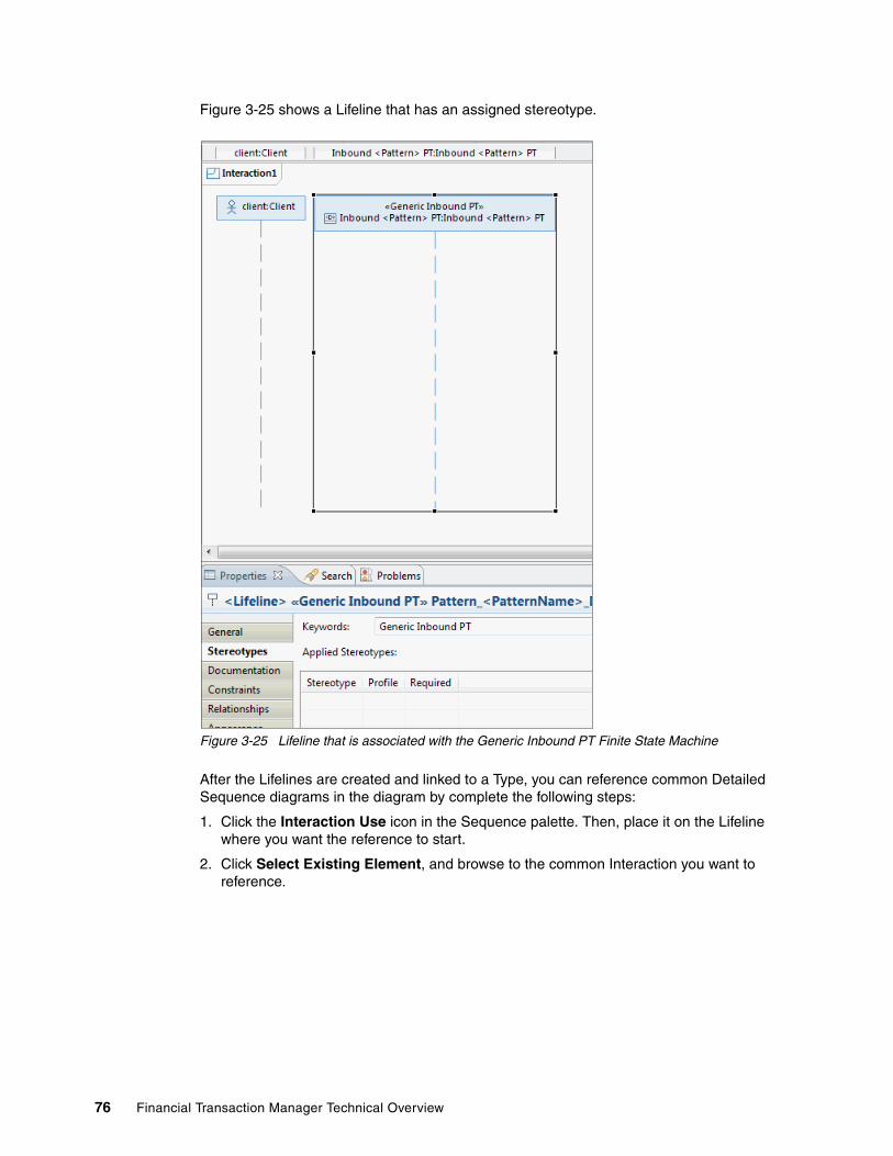
Figure 3-25 shows a Lifeline that has an assigned stereotype.
Figure 3-25 Lifeline that is associated with the Generic Inbound PT Finite State Machine
After the Lifelines are created and linked to a Type, you can reference common Detailed Sequence diagrams in the diagram by complete the following steps:
1. Click the Interaction Use icon in the Sequence palette. Then, place it on the Lifeline where you want the reference to start.
2. Click Select Existing Element, and browse to the common Interaction you want to reference.
76 Financial Transaction Manager Technical Overview

Figure 3-26 shows an example where you browse to the Log and Map Single Txn Interaction in the Patterns_Common model.
Figure 3-26 Referencing the Log and Map Single Txn Detailed Sequence diagram
3. If the process spans more than one Lifeline (which is usually the case), drag the reference box to include whichever Lifelines it affects. A window opens with a list of the Lifelines that the reference spans, which can be selected as appropriate.
4. As with the High Level Sequence diagram, add any Asynchronous Messages that are necessary, along with any further referenced Interactions
5. To emphasize any Financial Transaction Manager Lifelines/Components and to highlight the primary flow of the design, use the rounded rectangle from the Geometric Shapes palette as before. When placed, clear the highlighted text field because this information is not needed.
6. Send the rounded rectangle behind the Lifeline/Component images in the diagram by selecting Diagram Order Send to Back.
This step is optional and is meant only to improve the readability of the Detailed Sequence diagram.
Chapter 3. Producing design artifacts by using Rational Software Architect 77
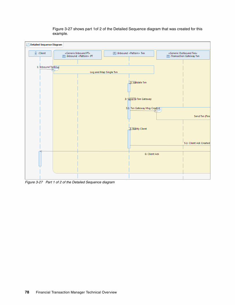
Figure 3-27 shows part 1of 2 of the Detailed Sequence diagram that was created for this example.
Figure 3-27 Part 1 of 2 of the Detailed Sequence diagram
78 Financial Transaction Manager Technical Overview

Figure 3-28 shows part 2 of 2 of the Detailed Sequence diagram that was created for our example.
Figure 3-28 Part 2 of 2 of the Detailed Sequence diagram
3.6 Object lifecycle diagrams
By following the Financial Transaction Manager methodology (see the Financial Transaction Manager V2.1 Information Center Financial Transaction Manager section overview), the Financial Transaction Manager objects and their states can be identified from the Detailed Sequence diagram or diagrams. Appendix F. Reference Applications in the Financial Transaction Manager V2.1 Information Center provides specific examples in two separate applications about how to identify the objects and their states. You can use these examples with the steps that are identified in the Detailed Sequence diagram to build an Object lifecycle diagram for each of the Financial Transaction Manager objects by creating basic state diagrams.
Note: This example shows two variations of detailed sequence diagrams. Some show objects only and their interactions, and some show objects that interact with components. The latter is used to show more fine-grained interactions but should be used with caution as to not clutter up the diagram with components.
Chapter 3. Producing design artifacts by using Rational Software Architect 79

To start creating a state diagram, the examples in this section create a package that is called Patterns_<PatternName> under the Object Lifecycle Diagrams package, with the intention that other state diagrams for other patterns can be added to their own package.
Complete the following steps to create a state diagram:
1. Right-click the package and then click Add UML Add Diagram State Machine Diagram.
2. Rename the created State Machine diagram to something appropriate.
3. Drag an Initial State, States, and Final States from the State Machine palette on to the diagram and suitably name them.
4. Link the states by clicking the Transition icon in the palette and then clicking the state that you want to begin with and drag the transition to the state to which you want to transition.
You are prompted to give the transition a name to indicate what is causing the transition from one state to another; for example, transaction mapped. A convention that we use is to not name the transition from the initial state to the first state.
5. To add an activity to a transition, right-click the transition and select Add UML Effect Create Activity.
6. Enter a suitable activity name; for example, Validate Transaction.
Figure 3-29 on page 81 shows the complete Object Lifecycle diagram for this example.
80 Financial Transaction Manager Technical Overview

Figure 3-29 A completed Object Lifecycle diagram
3.7 Object relationship diagrams
Complete the following steps to create an Object Relationship diagram that shows the logical relationship between Financial Transaction Manager objects:
1. Create a suitable package structure as with the previous diagrams.
2. Right-click the created package and select Add Diagram Class Diagram.
3. Rename the diagram to something appropriate.
4. From the Patterns_Common or Application Entities packages, drag the Data Types that you want to show.
Figure 3-30 on page 82 shows some of the Data Types available in the Application Entities package.
Chapter 3. Producing design artifacts by using Rational Software Architect 81

Figure 3-30 Drag Data Types on to the Class diagram
5. The Data Type stereotype can be removed (if wanted) by clicking Properties Appearance tab and by clicking Decoration in the Show Stereotype section.
Figure 3-31 shows the stereotype text removed for all objects in the diagram.
Figure 3-31 Removing the stereotype text
6. Complete the following steps to link the objects by using an association:
a. Click the Association icon in the palette.
b. If you want to indicate that control flows from one object to another, you can choose a Directed Association in the palette.
c. Click the object that you want to associate to another and drag the association to the other object.
d. Give the association a suitable name; for example, Cause.
82 Financial Transaction Manager Technical Overview

e. Right-click the association and select Delete from diagram for any attributes on the association that were created automatically that you do not want to show.
f. If you want to show multiplicity between the two objects, click the association and, in the Properties General tab, enter the Multiplicity entries as appropriate.
Figure 3-32 shows how to set the multiplicity on an association.
Figure 3-32 Changing the multiplicity settings
Figure 3-33 shows the completed Object Relationship diagram for this example.
Figure 3-33 Completed Object Relationship diagram
Chapter 3. Producing design artifacts by using Rational Software Architect 83

3.8 Finite State Machines
By following the Financial Transaction Manager methodology with the diagrams that are described in this chapter, you can create a set of Finite State Machines to describe and drive your processes.
Creating the physical Finite State Machine diagrams stems directly from the basic Object Lifecycle diagrams. You can copy a basic Object Lifecycle diagram and then refine the diagram step-by-step by formalizing the State and Event names, with the addition of Object Selectors, Override Selectors, Object Filters, Event Filters, Operator actions and alerts, and pseudocode to describe each action or activity with the definition of Events, Action, Configuration data, and so on, in their associated package structure.
All of these artifacts often are included within a separate Finite State Machine model and creating such is described in the Appendix C. Rational Model Tooling section in the Financial Transaction Manager V2.1 Information Center.
84 Financial Transaction Manager Technical Overview

Chapter 4. Mapping
A mapper is a runtime component that is used by Financial Transaction Manager to transform data that is received from an external source to Financial Transaction Manager’s internal canonical format (inbound mapper). It also can be used to transform from Financial Transaction Manager’s internal canonical format before it is sent to an external destination (outbound mapper).
This chapter provides only a high-level overview about how mapping is done in WebSphere Message Broker and WebSphere Transformation Extender. It is not meant to be a tutorial. For more information about mapping techniques, see the respective product’s information center.
This chapter includes the following topics:
� Internal standard format� Design considerations� Implementation considerations� Handling large files
4
© Copyright IBM Corp. 2014. All rights reserved. 85

4.1 Internal standard format
Over many years, the financial industry saw the proliferation of messaging standards and formats varying by region, country, and business functions. These formats include SWIFT MT, SWIFT MX, EDI, ISO20022, and CHAPS with country specific and bank-specific formats. Exchanging data in these formats can lead to complex architectures that contain transformations that have the following challenges:
� Large in number� Difficult to maintain and change� Reduce possibilities of reuse across systems and processes
Financial Transaction Manager simplifies these architecture challenges by introducing a canonical format called internal standard format (ISF). ISF represents financial transactions for internal processing that is based on the ISO20022 standard. The use of a canonical message format provides the following benefits:
� Simplified transaction processing
Financial Transaction Manger needs to work with a single format for the entire transaction lifecycle and that format is isolated from the details of external formats and protocols.
� Reduced number of transformations
Transformations are reduced by avoiding end-to-end transformations for every combination of input and output formats. The number of transformations is thus reduced to the total number of input and output formats in the solution. This process also isolates the change to a single transformation map for any standard, format, or regulatory change.
� Easily created shared services
Services can work with a single, consistent message format.
� Generic message processing
Allows processes or parts from one transaction to be reused in another without worrying about external formats.
� Simplified monitoring
Provides a consistent view of transactions across different formats, protocols, and processes on a central portal.
In the following sections, we describe the structure of ISF, its association with the ISO20022 standard, and extension points in ISF.
4.1.1 ISF overview
In Financial Transaction Manager, a transaction is a single unit of business activity that changes a financial position or information base. A single message or interchange with an external system can contain any number of transactions. Each transaction is distinguished by a unique purpose, including the following business purposes examples:
� Payment origination� Payment instruction� Advice� Invoice� Acknowledgement
86 Financial Transaction Manager Technical Overview

ISF defines a logical data model for the business content of a transaction and is implemented as XML schema that defines the content and structure of an XML document. The transaction that is represented by ISF is fully isolated from the details of external formats and protocols.
The ISF data model is extensible to support more application areas or requirements for a specific solution.
4.1.2 The ISO20022 standard
In this section, we summarize information about the ISO0022 standard. For more information about this standard, see this website:
http://www.iso20022.org/
ISO20022 is an international standard, which is proposed by ISO, for financial messages that includes the following components:
� A development methodology� A registration process� A central repository with a common data dictionary and business process catalog
The ISO20022 data dictionary defines a set of business components that represents a business entity, such as payments and party. This data dictionary provides the logical model on which the standard messages in the ISO20022 catalog of messages are based.
ISO20022 data dictionaryFigure 4-1 on page 88 shows the conceptual model of the ISO20022 data dictionary.
Note: ISF is delivered in Financial Transaction Manager as a set of XML schema files and an IBM WebSphere Message Broker message set.
Important: The ISO20022 standard does not define any messages. Instead, it provides a framework to define the messages. Within the governance of this framework, there are special interest groups for different business domains that are responsible for defining the message structures.
Chapter 4. Mapping 87
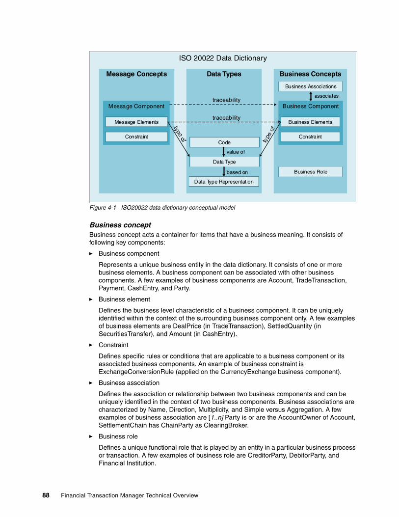
Figure 4-1 ISO20022 data dictionary conceptual model
Business conceptBusiness concept acts a container for items that have a business meaning. It consists of following key components:
� Business component
Represents a unique business entity in the data dictionary. It consists of one or more business elements. A business component can be associated with other business components. A few examples of business components are Account, TradeTransaction, Payment, CashEntry, and Party.
� Business element
Defines the business level characteristic of a business component. It can be uniquely identified within the context of the surrounding business component only. A few examples of business elements are DealPrice (in TradeTransaction), SettledQuantity (in SecuritiesTransfer), and Amount (in CashEntry).
� Constraint
Defines specific rules or conditions that are applicable to a business component or its associated business components. An example of business constraint is ExchangeConversionRule (applied on the CurrencyExchange business component).
� Business association
Defines the association or relationship between two business components and can be uniquely identified in the context of two business components. Business associations are characterized by Name, Direction, Multiplicity, and Simple versus Aggregation. A few examples of business association are [1..n] Party is or are the AccountOwner of Account, SettlementChain has ChainParty as ClearingBroker.
� Business role
Defines a unique functional role that is played by an entity in a particular business process or transaction. A few examples of business role are CreditorParty, DebitorParty, and Financial Institution.
ISO 20022 Data Dictionary
Message Concepts Data Types Business Concepts
Message Component
Message Elements
Constraint
Business Associations
Business Component
Business Elements
Constraint
Business Role
Code
Data Type
Data Type Representation
associates
value of
based on
traceability
traceability
88 Financial Transaction Manager Technical Overview

Figure 4-2 shows terms that are related to the ISO20022 data dictionary.
Figure 4-2 Dictionary components
Message conceptMessage concepts are the dictionary items that are used in defining messages. Message components are composed of the following key components:
� Message component
A reusable component for creating message definition. When you must convey certain information about a business notion in a message, it is unlikely that you must convey all of the information. Message components are derived from business components, but contain only the information that is relevant for a particular use. Multiple message components can be linked to the same business component.
In XML schema terms, message component is analogous to a complex type. A complex type can be a sequence or a choice component. For example, a CreditTransferTransaction message component can be derived from CreditTransfer business component. However, the message component includes information that is necessary to define the CreditTransferTransaction message component only.
� Message element
A characteristic of message component and is uniquely identified within the message component. A message element can be repeated multiple times within a message component. In such cases, multiplicity indicators [0..n] is added to the message element.
� Constraint
Defines specific conditions that are applicable to a message component. An example of message constraint is the AmountsCurrencyRule (applied on the message component SubscriptionCashFlow2).
Chapter 4. Mapping 89
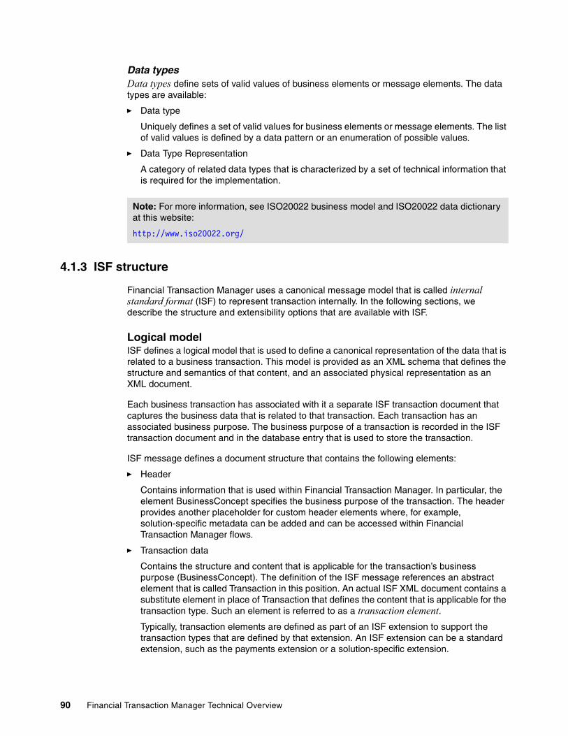
Data typesData types define sets of valid values of business elements or message elements. The data types are available:
� Data type
Uniquely defines a set of valid values for business elements or message elements. The list of valid values is defined by a data pattern or an enumeration of possible values.
� Data Type Representation
A category of related data types that is characterized by a set of technical information that is required for the implementation.
4.1.3 ISF structure
Financial Transaction Manager uses a canonical message model that is called internal standard format (ISF) to represent transaction internally. In the following sections, we describe the structure and extensibility options that are available with ISF.
Logical modelISF defines a logical model that is used to define a canonical representation of the data that is related to a business transaction. This model is provided as an XML schema that defines the structure and semantics of that content, and an associated physical representation as an XML document.
Each business transaction has associated with it a separate ISF transaction document that captures the business data that is related to that transaction. Each transaction has an associated business purpose. The business purpose of a transaction is recorded in the ISF transaction document and in the database entry that is used to store the transaction.
ISF message defines a document structure that contains the following elements:
� Header
Contains information that is used within Financial Transaction Manager. In particular, the element BusinessConcept specifies the business purpose of the transaction. The header provides another placeholder for custom header elements where, for example, solution-specific metadata can be added and can be accessed within Financial Transaction Manager flows.
� Transaction data
Contains the structure and content that is applicable for the transaction’s business purpose (BusinessConcept). The definition of the ISF message references an abstract element that is called Transaction in this position. An actual ISF XML document contains a substitute element in place of Transaction that defines the content that is applicable for the transaction type. Such an element is referred to as a transaction element.
Typically, transaction elements are defined as part of an ISF extension to support the transaction types that are defined by that extension. An ISF extension can be a standard extension, such as the payments extension or a solution-specific extension.
Note: For more information, see ISO20022 business model and ISO20022 data dictionary at this website:
http://www.iso20022.org/
90 Financial Transaction Manager Technical Overview

� Addenda
A placeholder for any other data that can be useful for a particular solution. The SWIFT mapper pack in Financial Transaction Manager uses the Addenda section to store and carry block 1, 2, 3, and 5 of the inbound SWIFT message, which can be reused in outbound mapping.
The element SourceData provides a place to record information about the source message that was mapped to the ISF document and can contain the complete content of the original input message.
For more information about ISF structure, see the Financial Transaction Manager Information center section by clicking Appendixes Appendix D. ISF Version 3 Structure.
XML schema structureA complete ISF schema is made up of core schema files that define common structures and extension schema files that add support for a specific application area (such as payments or securities) or a specific solution (such as SEPA credit transfer or international payments).
Typically, ISF extensions are provided as separate schema files that provide a new top-level schema file that imports the core schema files and imports or includes any other required extension schema files. For more information about the structure of the Payments extension and the sample application extension, see the Financial Transaction Manager information center section by clicking Appendixes Appendix D. ISF Version 3 Exensibility Standard extensions.
4.1.4 Extensibility
The ISF Core schema is extensible by using various extension methods that are supported by the XML schema standards. Typically, different application areas or specific solutions, introduce new transaction types (which often requires special transaction data content).
Typically, an extension is structured as one or more extension schema files that import the core schema and introduce other schema definitions, which define an ISF for a new domain.
Although by using XSD schema you can extend almost any type definition, Financial Transaction Manager defined standard extension points function, in the following ways, for ISF:
� Transaction data content� Use of derived types� The transaction document root element
Important: Addenda can contain any other elements that are qualified with a namespace prefix. Such elements need not be defined in the schema and are not checked for validity when the ISF document is validated to the schema.
Note: For more information about ISF structure, see Financial Transaction Manager information center Appendix D.
Tip: When you are defining extensions, use a separate target namespace from the core ISF namespace.
Chapter 4. Mapping 91
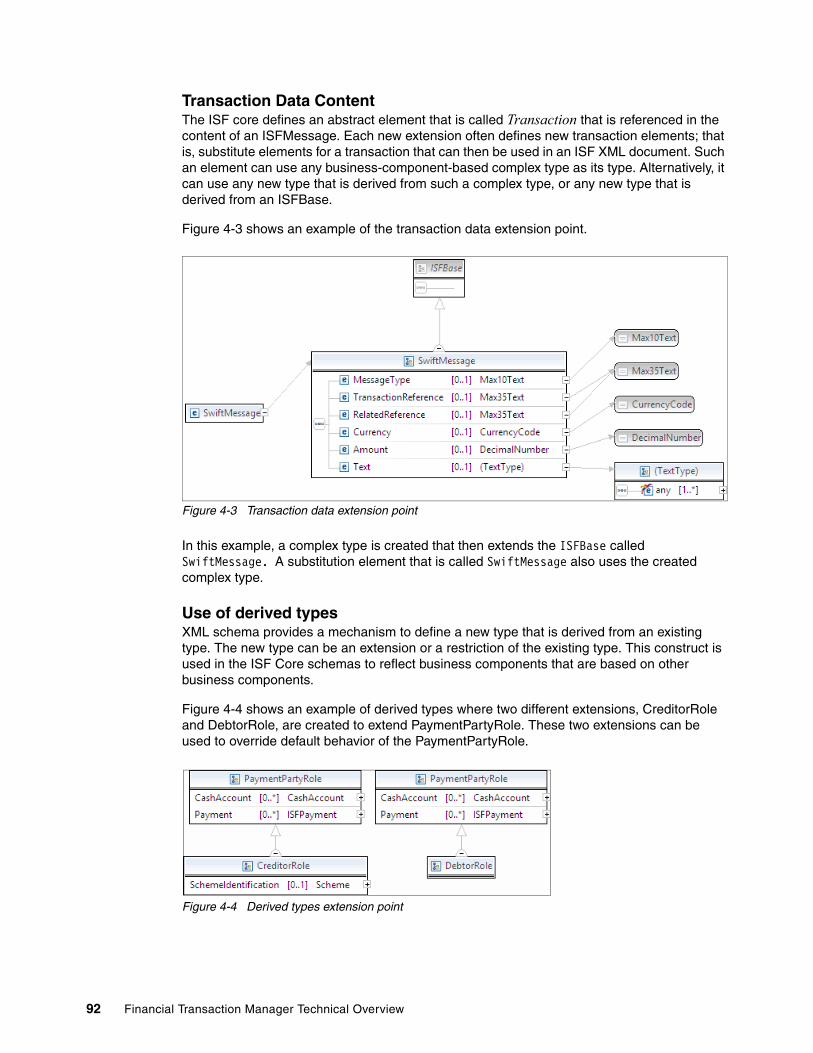
Transaction Data ContentThe ISF core defines an abstract element that is called Transaction that is referenced in the content of an ISFMessage. Each new extension often defines new transaction elements; that is, substitute elements for a transaction that can then be used in an ISF XML document. Such an element can use any business-component-based complex type as its type. Alternatively, it can use any new type that is derived from such a complex type, or any new type that is derived from an ISFBase.
Figure 4-3 shows an example of the transaction data extension point.
Figure 4-3 Transaction data extension point
In this example, a complex type is created that then extends the ISFBase called SwiftMessage. A substitution element that is called SwiftMessage also uses the created complex type.
Use of derived typesXML schema provides a mechanism to define a new type that is derived from an existing type. The new type can be an extension or a restriction of the existing type. This construct is used in the ISF Core schemas to reflect business components that are based on other business components.
Figure 4-4 shows an example of derived types where two different extensions, CreditorRole and DebtorRole, are created to extend PaymentPartyRole. These two extensions can be used to override default behavior of the PaymentPartyRole.
Figure 4-4 Derived types extension point
92 Financial Transaction Manager Technical Overview
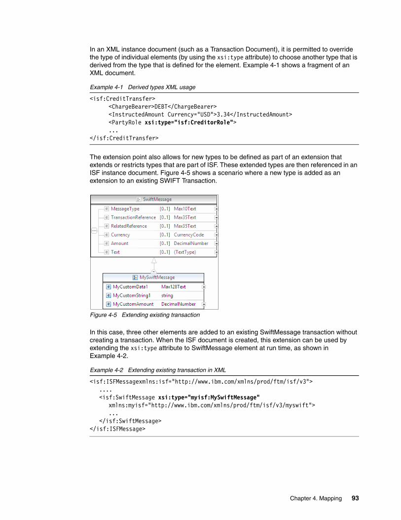
In an XML instance document (such as a Transaction Document), it is permitted to override the type of individual elements (by using the xsi:type attribute) to choose another type that is derived from the type that is defined for the element. Example 4-1 shows a fragment of an XML document.
Example 4-1 Derived types XML usage
<isf:CreditTransfer><ChargeBearer>DEBT</ChargeBearer><InstructedAmount Currency="USD">3.34</InstructedAmount><PartyRole xsi:type="isf:CreditorRole">...
</isf:CreditTransfer>
The extension point also allows for new types to be defined as part of an extension that extends or restricts types that are part of ISF. These extended types are then referenced in an ISF instance document. Figure 4-5 shows a scenario where a new type is added as an extension to an existing SWIFT Transaction.
Figure 4-5 Extending existing transaction
In this case, three other elements are added to an existing SwiftMessage transaction without creating a transaction. When the ISF document is created, this extension can be used by extending the xsi:type attribute to SwiftMessage element at run time, as shown in Example 4-2.
Example 4-2 Extending existing transaction in XML
<isf:ISFMessagexmlns:isf="http://www.ibm.com/xmlns/prod/ftm/isf/v3">....<isf:SwiftMessage xsi:type="myisf:MySwiftMessage"
xmlns:myisf="http://www.ibm.com/xmlns/prod/ftm/isf/v3/myswift">...
</isf:SwiftMessage></isf:ISFMessage>
Chapter 4. Mapping 93

Transaction document root elementThe ISF core provides a single element (called ISFMessage) that is the root element of an ISF XML document. However, another element of type ISFMessage (or of any new type that is defined as a restriction of ISFTransactionDocument) can also be used. This pattern is most likely to be of use when ISF is used as the basis for service interfaces.
Standard extensionsFinancial Transaction Manager provides already created extensions for Payments transactions with definitions of new transaction elements. They are called CreditTransfer, DirectDebit, Acknowledgement, and SwiftMessage.
For more information, see the Financial Transaction Manager information center by clicking Appendix D Extensibility Standard extensions.
4.2 Design considerations
Mapping design is the first step that is required to develop a mapper and is often performed by somebody with business analyst skills. The result of the design is a mapping specification. A mapping specification identifies the source format or target format and provides details about its content (element names, description, cardinality, structure, and so on).
Mapping specifications state whether the format represents a single transaction or multiple transactions. In the case of multiple transactions, the specifications provide further details. The details that are needed are how the structure of the message or file relates to the hierarchy of objects (BATCH and TRANSACTION that are related to the TRANSMISSION) in the Financial Transaction Manager data model that represents the message or file content. The specification provides details about values to populate columns in the Financial Transaction Manager tables and views.
The specification provides mapping details for those elements in the message or file that are mapped to the ISF content (path to element in ISF content and any relevant comments). These further details include direction on the handling of recurring structures or elements in the file or message. The details drill down further and include any information about conversion of data types, merging or splitting of fields, and mapping of code values.
Finally, the mapping specification is supported by samples for the message or file and related ISF documents (or EndMapper document for an inbound mapping).
In this section, the focus shifts to other aspects of mapping in Financial Transaction Manager. Because ISF is generic in nature and provides extensibility options, it is important to manage and govern the consistency of mapping for transactions that are created and mapped in Financial Transaction Manager. Failing to do so results in a many duplicate and unmanageable transaction types, which makes the overall solution less manageable and less reusable.
Although Financial Transaction Manager supports mapping of the entire inbound message to ISF, it is important to understand the performance implications of the mapping. In the following sections, we describe the techniques that optimize the mapping performance in the context of a solution.
94 Financial Transaction Manager Technical Overview

4.2.1 Guidelines for ISF usage
In this section, we describe the following guidelines:
� Business component selection� Using type override in ISF document instance� Appropriate Type override for Party and PartyIdentification elements� Ambiguous content duplication between base and extended types� Mapping BIC codes� Using extended Code Types� Using GenericIdentification� Using Addenda
Business component selectionWhen you are choosing a business component for a new transaction type or element, the following process is recommended:
� Use an existing business component type wherever possible. Any other business component type that is created adds to management and performance overhead.
� If an existing business component provides a good match for the required content but is missing content, create a type that extends the matching business component. For more information about this extension mechanism, see “Use of derived types” on page 92.
� If neither of these processes provide a good business component type match, create a type that extends ISFBase to include the required content. Such a type often uses existing business components as building blocks for the types of its elements. SWIFTMessage that is provided as part of Financial Truncation Manager is an example of this scenario.
ISF provides various business components in its schema definition. When you are mapping a new format to ISF, it is important to choose the correct business component for mapping. The choice of business component should be considered in the following contexts:
� Transaction level business component
This business component in ISF is for mapping at the business transaction level. Extra attention should be given when there are multiple options available in ISF for a single business component in the inbound business component.
The first decision to make when you are mapping to a new source or target format is to choose the appropriate element (substitute for “Transaction” in ISFMessage) that contains the business content of the transaction. If the format represents transactions are payments, one of the elements CreditTransfer or DirectDebit (of type CreditTransfer and DirectDebit, respectively) is likely to be appropriate.
If the format represents transactions are related to payments, such as payment status, return, and recall, an element that uses the type (or extension of) Acknowledgement is likely to be suitable. The acknowledgement structure provides the content to map the relationship to the original payment together with status and reason information. Other properties of the original payment can be mapped to elements, such as, OriginalMessageStatusInformation, TransactionStatusInformation, and OriginalTransaction.CreditTransfer.
The structure of the acknowledgement type can be used to represent status information for a single transaction, a more complex batch of multiple transactions, or multiple batches each with multiple transactions. The structure of the acknowledgement type can also be suitable for the response (in the case of services that are based on request and response messages).
In the case of formats that represent statements, credit and debit advice, and so on, the element AccountReport (type ISFAccountReport) can be suitable.
Chapter 4. Mapping 95

In other cases, the first step is to see whether an ISF type, which represents a business component in the ISO 20022 Data Dictionary, provides the semantics and content to represent the format (such as, CashEntry, AccountEntry, and ISFInvoice). If no such type exists, an extension to the ISF should be considered.
Finally, a general purpose (substitute for transaction) element (which is called wrapper) is provided. This element, whose type ISFWrapper, is defined to contain wildcard content and can be used to contain arbitrary elements as required. This can be useful when you are mapping miscellaneous messages (where the content does not match a suitable ISO 20022 component and the explicit modeling of the content by an ISF extension is not required).
� Solution level business component
It is important to maintain consistency of the ISF document across the interfaces and transactions in Financial Transaction Manager. Choosing the same business component for a particular business concept across the transactions ensures maximum reuse, compatibility, and consistency. For example, Creditor Information in SWIFT MT103 messages and PAIN001 messages should be mapped to same business component in ISF. This allows consistent processing of transactions across the formats.
Using type override in ISF document instanceWhen you are constructing an ISF document, it might be necessary to override the type of an element for the following reasons:
� To determine the semantic of an element. For example, in instances where you must discern when to use which of the following options:
PartyRoleCreditTransfer.PartyRole[xsi:type=DebtorRole]...CreditTransfer.PartyRole[xsi:type=CreditorRole]...
In such case, when you are accessing the content of an ISF document, it is necessary to qualify the element to ensure that it has the appropriate type extension to interpret the content correctly.
� To include subelements that are defined as part of the extended type. For example, when you are considering PaymentExecution, as shown in the following example:
CreditTransfer.PaymentExecution[xsi:type=PaymentInstruction].SettlementInstruction...
In such a case, when the content of an ISF document is accessed, the qualification is not necessary; it is sufficient to be able to determine whether the subelement is present, as shown in the following example
CreditTransfer.PaymentExecution.SettlementInstruction...
This is consistent with a path to access elements in the base type in a manner that is not sensitive to whether a type extension was used. Consider the following for example:
CreditTransfer.PaymentExecution.Identification
For more information about the use of derived types, see Financial Transaction Manager information center and click Appendixes Appendix D. ISF Version 3 Exensibility Use of derived types
Appropriate Type override for Party and PartyIdentification elementsOne of the key business components of ISF is Party.Properties of a party. They are often stored in the ISF in the context of ...YyyyRole[xsi:type=XxxxxxxxRole].Player... with more information in ...YyyyRole[xsi:type=XxxxxxxxRole].Player.Identification...
96 Financial Transaction Manager Technical Overview

Here, Yyyy, is any type of role, such as PartyRole, PaymentPartyRole, and Xxxxxxxx denotes specific extensions, such as CreditorRole and DebtorRole.
If the party must be a financial institution (for example, XxxxxAgentRole), use FinancialInstitution as the type for Player, and OrganisationIdentification for Identification, as shown in the following syntax:
...YyyyRole[xsi:type=XxxxxAgentRole].Player[xsi:type=FinancialInstitution].Identification[xsi:type=OrganisationIdentification]...
If the party is a person (which means date of birth or passport number identification information is specified), use Person as the type for Player, and PersonIdentification for Identification, as shown in the following syntax:
...YyyyRole[xsi:type=XxxxxAgentRole].Player[xsi:type=Person].Identification[xsi:type=PersonIdentification]...
Otherwise, use Party as the type for Player (Organisation can also be used, but is unlikely to be required), and OrganisationIdentification for Identification, as shown in the following syntax:
...YyyyRole[xsi:type=XxxxxAgentRole].Player[xsi:type=Party].Identification[xsi:type=OrganisationIdentification]...
In the case of ISO messages (such as pain.001), when mapping the party information that is defined by the PartyIdentification32 type, the presence of the element PrivateIdentification can be used to denote that the party should represent a person.
Ambiguous content duplication between base and extended typesIn many cases, there is ambiguity between whether to map content to an element in the content of base type of an element or whether to map to an element that is introduced by an extended type. Continuing with the example that was used in the previous section, following syntax is used:
...YyyyRole[xsi:type=XxxxxxxxRole].Player...
The element Player can be overridden to the type Party or other types, such as Person, Organisation, or FinancialInstitution that extend Party. Party contains the element (Identification) that is of type PartyIdentification. Organisation includes all the elements of Party and adds further elements, one of which is OrganisationIdentification (which is of type OrganisationIdentification, an extension of PartyIdentification). Similar patterns can be seen in many other extended types. For example, Person, FinancialInstitution (which also extends Party), CashAccount (which extends Account options of CashBalance and CashEntry as opposed to Balance and Entry).
Generally, it is preferable to use the element that is provided in the base type and override the type of that element, if appropriate. This means that the location of the basic properties is the same, regardless of which type overrides are used.
For example, to locate the name of a party, see the following syntax:
...YyyyRole[xsi:type=XxxxxxxxRole].Player.Identification.PartyName.Name
This location is consistent regardless of which overrides are provided for the type of the elements Player.
Chapter 4. Mapping 97

Mapping BIC codesThe following syntax shows the preferred location for BIC code for a party that must be a financial institution:
...YyyyRole[xsi:type=XxxxxAgentRole].Player[xsi:type=FinancialInstitution].Identification[xsi:type=OrganisationIdentification].BICFI
The following syntax shows the preferred location for BIC code for a party that might or might not be a financial institution (in ISO messages can be identified as BICOrBEI):
...YyyyRole[xsi:type=XxxxxAgentRole].Player[xsi:type=Party].Identification[xsi:type=OrganisationIdentification].AnyBIC
For completeness, many outbound maps check the preferred and non-preferred possible locations for a BIC code that uses functions, such as COALESCE in ESQL. For example, the following locations are checked for Party that must be a financial institution:
� ...Player.Identification.BICFI� ...Player.BICFI
The following areas are checked for Party that might or might not be a financial institution:
� ...Player.Identification.AnyBIC� ...Player.Identification.BICNonFI� ...Player.Identification.BICFI� ...Player.BICFI
Using extended Code TypesThe ISF contains many simple types, which correspond to types in the ISO 20022 Data Dictionary that define a finite set of enumerated values.
In many cases, an element of this type in the ISF content is the most logical mapping for an element of similar semantics in a message or file format. However, the range of values in the message or file format cannot be matched to the finite set of values that are defined in the ISO 20022 Data Dictionary.
In such cases, the ISF often contains a replacement type definition that extends the original type following a common pattern. The new type is defined as a union of the original code type and Max35Text, with the addition of an attribute that is called CodeIssuer.
The union with Max35Text extends the value space to allow arbitrary code values. The preservation of the original type in the union maintains the link that the new type is an extension of the code type from which the set of enumerated values might be used by a mapping tool. The attribute, CodeIssuer, allows the value to be qualified.
Example1Many ISO messages contain elements that contain code values, with separate sub elements for code (of a specific enumerated type), and proprietary (unspecified value).
For example, in the pain.001 message, for the LocalInstrument code, CstmrCdtTrfInitn.PmtInf.CdtTrfTxInf.PmtTpInf.LclInstrm.Cd (type: ExternalLocalInstrument1Code) can be mapped to CreditTransfer.PaymentExecution[xsi:type=PaymentInstruction].ProcessingInstructions.LocalInstrument and CreditTransfer.PaymentExecution[xsi:type=PaymentInstruction].ProcessingInstructions.LocalInstrument.CodeIssuer set to fixed value ExternalLocalInstrument.
98 Financial Transaction Manager Technical Overview

Also, CstmrCdtTrfInitn.PmtInf.CdtTrfTxInf.PmtTpInf.LclInstrm.Prtry (type: Max35Text) can be mapped to CreditTransfer.PaymentExecution[xsi:type=PaymentInstruction].ProcessingInstructions.LocalInstrument.
The value set to the attribute, CodeIssuer, is derived from the type name of the ISO message element by removing the suffix nnCode.
For outbound mapping, the choice between mapping to the Cd or Prtry elements can be made by checking whether the value matches a permitted value for Cd, or by the value of the CodeIssuer attribute.
Example2In the Swift MT103 message, field 72 can specify sender to receiver information, which is mapped to an instruction for the next agent. The field might contain fixed code values, such as CHQB, HOLD, and PHOB. These are standard instruction codes and can be mapped to CreditTransfer.PaymentExecution[xsi:type=PaymentInstruction].InstructionForNextAgent.Code.
Alternatively, the field can contain arbitrary bilaterally agreed codes, which might be mapped as CreditTransfer.PaymentExecution[xsi:type=PaymentInstruction].InstructionForNextAgent.Code with CreditTransfer.PaymentExecution[xsi:type=PaymentInstruction].InstructionForNextAgent.Code.CodeIssuer set to fixed value SwiftF72.
The value set to the attribute, CodeIssuer, indicates that the value relates to usage in the context of the Swift message field 72.
Using GenericIdentificationThe ISF schemas provide a complex type (which is called GenericIdentification) that is derived from the business component of the same name in the ISO 20022 Data Dictionary. This is used to represent arbitrary qualified identification information; for example, as part of party identification and account identification.
Many ISO 20022 messages contain identification information that is based on the business component. In each case, the identification information consists of some or all of the following information:
� Scheme
Identifies the type of identifier to be specified. For example, in the case of a person, you can use passport number, driving license number, or national identity number. For an organization, you can use tax identification number, employer identification number, and so on.
� Issuer
Identifies the authority that issues the identifiers. This can be a country code (in the case of passport numbers or tax identification numbers) or country code and district or state (in the case of a driver license number).
� Identification
The actual identification value; for example, a driver license number.
Chapter 4. Mapping 99

The identification information can be mapped to the following subelements that are defined in GenericIdentification:
� Scheme can be mapped to ...Scheme.NameShort and set to a code value that identifies the scheme; for example, DRLC for driver license number and CCPT for passport number. This can be further qualified by ...Scheme.DomainValueCode, which can be set to a value that identifies the set of codes to which the NameShort value belongs. For example, the use of ExternalPersonIdentification to identify the ISO 20022 external code list of person identification codes or ExternalOrganisationIdentification to identify the ISO 20022 external code list of organization identification codes.
� Issuer can be mapped to ...PartyRole.OwnerCode
� Identification can be mapped to ...Identification
The following construct can also be used, for example, to represent the clearing system member identification of a Financial Institution:
� Scheme can be used my setting ...Scheme.NameShort to a value CHID.
� Issuer can be mapped to ...PartyRole.OwnerCode by setting the code to identify the clearing system scheme. For example, GBDSC for the Bank Branch Code that is used in the UK.
� Identification can be used by setting ...Identification to the identification value; for example, the Bank Branch Code.
Using AddendaUse the addenda section of the ISF document to store the data from the inbound message that is either not part of the core business data or is not needed to be accessed by the business process throughout the transaction lifecycle. This addenda is carried through the transaction lifecycle and is available to all the actions and mappers in the solution. For example, SWIFT mapper pack, in Financial Transaction Manager, uses addenda section to store block 1, 2, 3, and 5 of the inbound SWIFT message. This information is available to the outbound mappers if they need it.
The SourceData element in the addenda can be used to store an XML rendering of (or string values for) the content of the original message with information about the original format (message type, message set name, and so on).
4.2.2 Mapping level considerations
In this section, we focus on various aspects that must be considered when the mapping specification for an interface is created. Although industry-level interfaces are standard (such as SWIFT and SEPA), financial institutions have their own set of requirements around these interfaces.
Note: The ISO 20022 external code list of External Clearing System Identification Codes provides a list of codes for different clearing systems.
Note: ISF is an XML document that is typically parsed in its entirety (but can be avoided because of WebSphere Message Broker parsing on-demand capability). Adding content to the addenda makes the ISF document larger and can add parsing overhead.
100 Financial Transaction Manager Technical Overview

These requirements concern the following areas:
� Amount of processing to be done on a message.
� Amount of information to be monitored in a transaction.
� Frequency of messages; for example, steady load single transactions, burst load single transactions, hourly batches, and end of day batches.
A financial transaction contains large amounts of information. However, in many cases, most of this information is pass-through. Regarding Financial Transaction Manager, pass-through means that only a few attributes of the inbound transaction are used for processing. The rest of the information is sent to external interfaces without change. However, there are scenarios where almost all the information that is present in the inbound transaction must be used through the business process; for example, interactions with accounting systems and compliance checks.
These scenarios require different levels of mapping from inbound message to ISF and from ISF to outbound messages. The extensible nature of ISF provides multiple options to perform in-depth or high-level mapping of an inbound message to ISF. Some of these mapping techniques are described in the following section.
Consider an example scenario where Financial Transaction Manager receives SWIFT messages from all the series (0 - 9) on a single channel. The following processing requirements of these messages are needed:
� Financial Transaction Manager should consider only MT103, MT202, and MT942 messages for full lifecycle management.
� All of the remaining messages should be sent directly to the SWIFT gateway for processing.
� Every transaction should be logged in Financial Transaction Manager database regardless of SWIFT message type.
� SWIFT MT202 and MT942 messages should be routed to predefined system interfaces.
� SWIFT MT103 messages should be enriched based on certain fields of the message.
In the following section, we describe various mapping techniques in the context of these requirements.
Pass-through mappingPass-through mapping is a concept that often applies to outbound mapping when the message to be sent out is the same as the message that was received (no transformation). The outbound mapping passes through the raw content of the original input message. Pass-through mapping can be used with shallow or deep mapping at the inbound side.
AdvantagesPass-through mapping has the following advantages:
� Best mapping performance because there is virtually no data to map.� Single mapper can be used for multiple formats.� Minimal development and testing time.
DisadvantagesPass-through mapping has the following disadvantages:
� Performance overhead of carrying original raw data with ISF document.
� Any modifications or enrichments that are made to the transaction data cannot be sent to outbound systems.
Chapter 4. Mapping 101

Shallow mappingIn terms of runtime overhead and development effort, shallow mapping is lower in cost. It is appropriate where format transformation or enrichment is not being used and only a part of the message content is needed in the canonical representation. Shallow mapping can be used with the storage of original message content within Addenda.
When shallow inbound mapping is used, pass-through outbound mapping can be used or original message content (stored in Addenda) can be used by outbound mapping to efficiently construct the outbound message.
In our example scenario, consider the requirement for processing SWIFT MT 202 and MT942 messages, which states that SWIFT MT202 and MT942 messages should be routed to predefined system interfaces. To fulfil this requirement, these messages must be mapped to ISF to use the lifecycle management capabilities of Financial Transaction Manager.
The destinations of these messages are fixed at design time. Thus, every attribute in the message might not be required for transaction processing. In such a scenario, mapping specification should map only the key attributes of the inbound message to ISF. The remaining information can be discarded or carried in the addenda section of the ISF document to the output mappers where the original message can be re-created, if required.
AdvantagesShallow mapping has the following advantages:
� High performance maps, as limited information is mapped.
� Smaller development and testing time as compared to full mapping.
� Easy to upgrade to deep mapping pattern at a later stage if required with minimal impact.
� Transactions can be searched by using the Financial Transaction Manager user interface, which is based on mapped attributes.
� Transactions can use the full lifecycle capabilities of Financial Transaction Manager.
DisadvantagesShallow mapping has the following disadvantages:
� Limited information is available for transaction processing.� Higher CPU and memory requirement for mapping than pass-through mapping.� Unlikely to use pre-made mappers from Mapper pack of Financial Transaction Manager.� Limited Key Performance Indicators (KPI) can be tracked.
Deep mappingIn our example scenario, consider the requirement that states that SWIFT MT103 messages should be enriched based on certain fields of the message. To fulfil this requirement, each attribute in the transaction must be mapped to ISF. Being mapped to ISF enables Financial Transaction Manager to run enrichment rules against these attributes to decide which fields must be enriched. Further, actual enrichment is done on certain fields of the message.
For commonly used SWIFT MT messages, Financial Transaction Manager already provides ready-to-use mappers and their specifications. For other formats, mapping specification and mapper code must be created. The Financial Transaction Manager information center provides mapping specification for MT103 format, which can be taken as reference for creating other mapping. The mapping is shown in Figure 4-6 on page 103.
Note: For more information about and supported formats of Mapper pack, see Appendix J in the Financial Transaction Manager information center.
102 Financial Transaction Manager Technical Overview
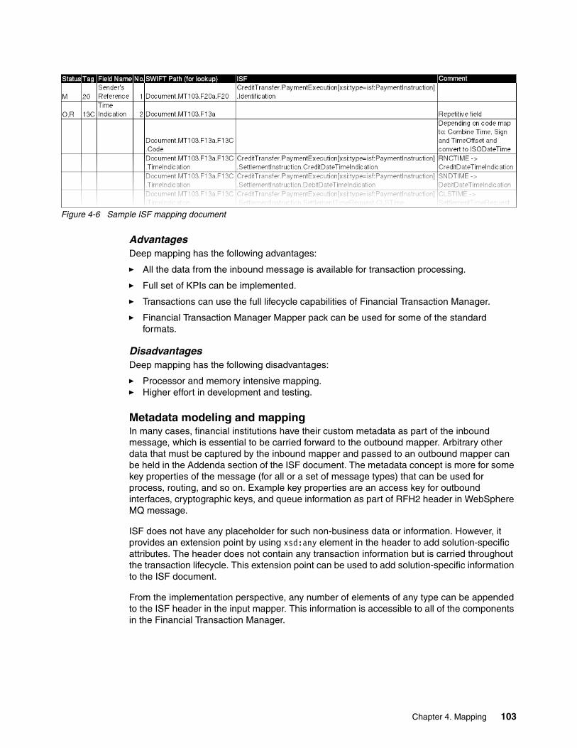
Figure 4-6 Sample ISF mapping document
Advantages Deep mapping has the following advantages:
� All the data from the inbound message is available for transaction processing.
� Full set of KPIs can be implemented.
� Transactions can use the full lifecycle capabilities of Financial Transaction Manager.
� Financial Transaction Manager Mapper pack can be used for some of the standard formats.
DisadvantagesDeep mapping has the following disadvantages:
� Processor and memory intensive mapping.� Higher effort in development and testing.
Metadata modeling and mappingIn many cases, financial institutions have their custom metadata as part of the inbound message, which is essential to be carried forward to the outbound mapper. Arbitrary other data that must be captured by the inbound mapper and passed to an outbound mapper can be held in the Addenda section of the ISF document. The metadata concept is more for some key properties of the message (for all or a set of message types) that can be used for process, routing, and so on. Example key properties are an access key for outbound interfaces, cryptographic keys, and queue information as part of RFH2 header in WebSphere MQ message.
ISF does not have any placeholder for such non-business data or information. However, it provides an extension point by using xsd:any element in the header to add solution-specific attributes. The header does not contain any transaction information but is carried throughout the transaction lifecycle. This extension point can be used to add solution-specific information to the ISF document.
From the implementation perspective, any number of elements of any type can be appended to the ISF header in the input mapper. This information is accessible to all of the components in the Financial Transaction Manager.
Chapter 4. Mapping 103

Define a ComplexType and associated element definition for all the header elements. Then, add this element to the header rather than adding individual elements. This approach improves maintenance and reusability of the header across interfaces and message formats, as shown in Figure 4-7.
Figure 4-7 Metadata modeling example
4.3 Implementation considerations
A mapper is a WebSphere Message Broker subflow that is started to perform the mapping. The mapper subflow uses one or more nodes that are provided by WebSphere Message Broker to perform the parsing and transformation of messages. For more information about developing Mappers, see Chapter 5, “Using WebSphere Message Broker Toolkit to produce build artifacts” on page 131.
In this section, we describe implementing mapping in Financial Transaction Manager by using various options for mapping that is offered by the underlying WebSphere Message Broker platform. Financial Transaction Manager also includes support for mapping by using WebSphere Transformation Extender.
Each of these technologies has different parsing and mapping constructs. They also have different artifacts that must be produced as part of the mapping.
4.3.1 Parsing
Parsing in Financial Transaction Manager refers to an activity where a physical wire format is translated into a logical message tree. This tree can be validated against a message definition and can be accessed by using expressions that are similar to XPath. WebSphere Message Broker and WebSphere Transformation Extender have native supports for modeling, parsing, and validating messages. These techniques are described in the following sections.
104 Financial Transaction Manager Technical Overview

WebSphere Message Broker message setsMessages can be modeled in WebSphere Message Broker by using message sets. A message set for ISF is included with Financial Transaction Manager that can be imported into WebSphere Message Broker Toolkit. Figure 4-8 shows the properties of the message set.
Figure 4-8 ISF Message Set
The message set supports the following domains:
� XMLNSC
This is used in most cases as an XMLNSC parser in WebSphere Message Broker because of its high performance.
� MRM
MRM domain is added to retain support for earlier versions of Financial Transaction Manager.
For other inbound and outbound messages, WebSphere Message Broker provides a capability to create message sets and definitions by importing message definitions in one of the formats that are shown in Figure 4-9.
Figure 4-9 Message definition import options
The following options are available:
� C Header File� COBOL File� CORBA IDL File� Database Definition File
Chapter 4. Mapping 105

� IBM Supplied Message� SCA Import or Export� WSDL File� XML DTD File� XML Schema File
Additionally, message sets and definitions can be modeled manually by adding elements and types by using Message Set Editor, as shown Figure 4-10.
Figure 4-10 Message set editor
After the message set is created, it can be used in multiple WebSphere Message Broker nodes to parse and validate the message, such as the following constructs:
� Input nodes� Reset content descriptor node (RCD node)� ESQL function PARSE
For more information, see WebSphere Message Broker Support pack IP04: WebSphere Message Broker: Designing for Performance for best practices, which is available at this website:
http://www-01.ibm.com/support/docview.wss?uid=swg24006518
Note: For more information about message set modeling, see the WebSphere Message Broker information center by clicking Developing message flow applications Constructing message models.
Note: It is important to note that parsing and validating message trees is one of the most CPU and memory intensive operations. Thus, message flows should be designed to minimize parsing and validation operations.
106 Financial Transaction Manager Technical Overview
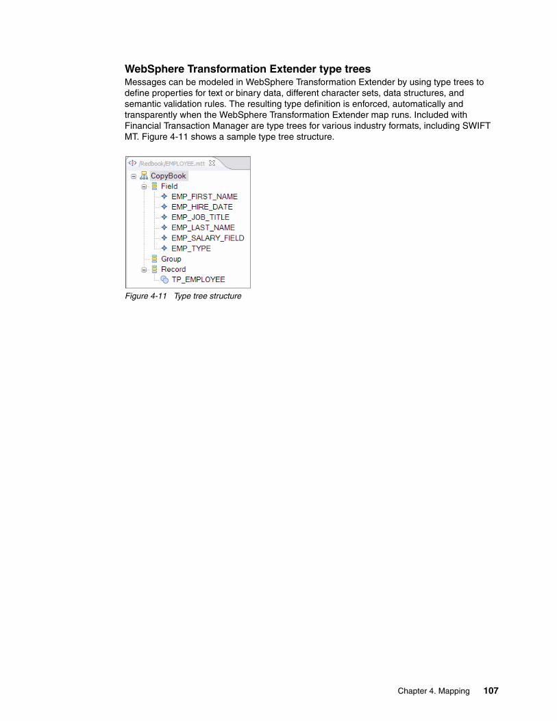
WebSphere Transformation Extender type treesMessages can be modeled in WebSphere Transformation Extender by using type trees to define properties for text or binary data, different character sets, data structures, and semantic validation rules. The resulting type definition is enforced, automatically and transparently when the WebSphere Transformation Extender map runs. Included with Financial Transaction Manager are type trees for various industry formats, including SWIFT MT. Figure 4-11 shows a sample type tree structure.
Figure 4-11 Type tree structure
Chapter 4. Mapping 107

Similar to WebSphere Message Broker, WebSphere Transformation Extender supports creating type trees by importing existing structural definitions by using multiple options. Figure 4-12 shows the possible import options.
Figure 4-12 Create type tree by using import
Inside WebSphere Transformation Extender, create the type trees by using XML schema import feature when the format is XML (rather than native WebSphere Transformation Extender type trees). This is true especially for WebSphere Message Broker integration because it allows closer binding to the WebSphere Message Broker XMLNSC domain (which is more efficient). However, in some circumstances, the XMLNSC binding can be unsupported. Thus, the integration flows must support the BLOB and XMLNSC domain for the ISF bindings.
More information: For more information about type trees, see the WebSphere Transformation Extender information center, which is available at this website:
http://pic.dhe.ibm.com/infocenter/wtxdoc/v8r3m0/index.jsp
108 Financial Transaction Manager Technical Overview

Java Validation ComponentThe Java Validation Component provides a framework for validating SWIFT messages within WebSphere Transformation Extender.
The Java Validation Component can be used to check messages before they are transmitted to the SWIFT network to ensure compliance. It provides a configurable validation framework with error reporting functionality, which allows the source of the error to be quickly located. The component is typically used when the requirement is to validate only the message rather than transformation.
The Java Validation Component validates the following data in accordance with the latest SWIFT standards:
� Message syntax (presence and order of fields and sequences)� Field syntax (size and data type)� Field and sequence cardinality (optional, mandatory, and repeating)� Code words� Network validated rules at both message and field level� Message envelope syntax (SWIFT header and trailer)� Market practice rules
For more information about configuring Java Validation Component, see the Financial Transaction Manager information center by clicking Application programming Mappers WTX Mappers WTX SWIFT Maps Java Validation Component.
4.3.2 Mapping technologies
The mapper in Financial Transaction Manager is responsible for conversion between the external message format and the internal ISF. The input mappers transform external messages into ISF Document and output mappers transform ISF Documents into external format.
WebSphere Message Broker (optionally with WebSphere Transformation Extender) provides various options to perform this transformation. Each of these options is described in this section.
ESQL mappingThis is one the most common and frequently used mapping technologies in Financial Transaction Manager. It involves adding a compute node and a corresponding ESQL module to perform mapping to or from ISF to an external format, as shown in Figure 4-13.
Figure 4-13 ESQL mapper flow
Important: The Java Validation Component validates all user to user messages; that is, all of the Category 1 (MT1nn) through Category 9 (MT9nn). However, Category 0 (MT0nn) Service and System Messages are not validated by the Java Validation Component.
Chapter 4. Mapping 109

The input message (ISF or external format) must be parsed to perform mapping. If not already parsed, the ESQL module can use the PARSE function to construct the logical message tree for mapping.
In ESQL, mapping involves the construction of the output tree by using a series of assignment or create statements. These statements must be run such that the order of the elements in the output tree matches the required structure that is defined by the message set or schema (or any other format). You can achieve this output by using the following process:
1. Create empty elements in the correct order, including the creation of output message skeletons without any values, such that the structure of the output matches the required output format, as shown in Example 4-3.
Example 4-3 Create output structure in ESQL
CREATE LASTCHILD OF rIsfTxn AS rISFChequeIssue NAME 'CreditMethod';SET rISFChequeIssue.(XMLNSC.Attribute){INMAP_XSI_NS}:type='isf:ChequeIssue';
CREATE LASTCHILD OF rIsfTxn NAME 'EquivalentAmount';CREATE LASTCHILD OF rIsfTxn NAME 'EndToEndIdentification';CREATE LASTCHILD OF rIsfTxn NAME 'ExchangeRateInformation';CREATE LASTCHILD OF rIsfTxn NAME 'InstructedAmount';CREATE LASTCHILD OF rIsfTxn NAME 'InstructionForCreditorAgent';CREATE LASTCHILD OF rIsfTxn NAME 'InstructionForDebtorAgent';
--------------------------------------------------------------------Create CreditTransfer.PartyRoles------------------------------------------------------------------
--Create CreditTransfer.PartyRole(xsi:type=DebtorRole) and keep the referenceCREATE LASTCHILD OF rIsfTxn AS rISFDebtorRole NAME 'PartyRole';SET rISFDebtorRole.(XMLNSC.Attribute){INMAP_XSI_NS}:type='isf:DebtorRole';
--Create CreditTransfer.PartyRole(xsi:type=CreditorAgentRole) and keep the ref.CREATE LASTCHILD OF rIsfTxn AS rISFCredtAgtRle NAME 'PartyRole';SET rISFCredtAgtRle.(XMLNSC.Attribute){INMAP_XSI_NS}:type='isf:CreditorAgentRole';
--Create CreditTransfer.PartyRole(xsi:type=CreditorRole) and keep the referenceCREATE LASTCHILD OF rIsfTxn AS rISFCreditorRole NAME 'PartyRole';SET rISFCreditorRole.(XMLNSC.Attribute){INMAP_XSI_NS}:type='isf:CreditorRole';
2. Populate the output values from input message. This output is the actual mapping phase where mapping logic is applied to copy values from the input message to output message per the mapping specification, as shown in Example 4-4.
Example 4-4 Populate output values in ESQL
--------------------------------------------MapCreditTransfer.PaymentExecution(xsi:type=ISFPaymentInstruction)------------------------------------------DECLARE rInputPmtId REFERENCE TO rInputCdtTrfTxInf.*:PmtTpInf;
IF NOT LASTMOVE(rInputPmtId) THEN MOVE rInputPmtId TO rInPmtInf.*:PmtTpInf;
END IF;
110 Financial Transaction Manager Technical Overview

SET rISFPaymInstr.Identification = rInputCdtTrfTxInf.*:PmtId.*:InstrId;SET rISFPaymInstr.Priority = rInputPmtId.*:InstrPrty;SET rISFPaymInstr.SettlementInstruction.PaymentTaxDetails = rInPmtInf.*:Tax;
3. Delete unused elements by removing the unused or unnecessary elements. This step keeps the structure clean and reduces the overhead of carrying the empty elements in subsequent flow, as shown in Example 4-5.
Example 4-5 Delete unused elements
--Remove empty fieldsIF NOT EXISTS(rISFPaymInstr.ProcessingInstructions.ServiceLevel.*[]) THEN
DELETE FIELD rISFPaymInstr.ProcessingInstructions.ServiceLevel;END IF;
IF NOT EXISTS(rISFPaymInstr.ProcessingInstructions.*[]) THENDELETE FIELD rISFPaymInstr.ProcessingInstructions;
END IF;
IF NOT EXISTS(rISFPaymInstr.SettlementInstruction.*[]) THENDELETE FIELD rISFPaymInstr.SettlementInstruction;
END IF;
Additionally, the mapping logic might need access to Financial Transaction Manager configuration data for conditional processing. Financial Transaction Manager provides a number of ESQL helper functions to access the cached configuration data. For more information, see the Financial Transaction Manager information center by clicking Application programming Static Data Cache.
Java mappingThe mapping can be implemented in Java if it is the enterprise-level technology choice. The message tree that includes the environment tree can be accessed by using Java methods that are provided by WebSphere Message Broker.
Java can be used in WebSphere Message Broker by using one of the following methods:
� Calling out to a Java procedure from a compute node� Use of Java code in a Java Compute node
Note: You might need to break the process into multiple sections of the message to achieve the most efficient method of mapping.
Note: For more information about ESQL functions, see the Reference Message flow development Transformation interfaces ESQL section in the WebSphere Message Broker information center.
Note: There are no Java helper functions provided to access Financial Transaction Manager configuration data. Therefore, manual coding or solution-specific functions must be created to achieve the same.
Chapter 4. Mapping 111

Calling out to a Java procedure from a compute nodeIn ESQL, Java methods can be started by declaring them as external functions. However, ESQL code can start only static methods that are defined in Java classes. The Java code implementation for the methods can by deployed to the same run group that the ESQL is deployed to or can be added as a shared library to the broker run time.
Example 4-6 shows a sample ESQL declaration for Java method.
Example 4-6 ESQL declaration of Java methods
CREATE FUNCTION MapTransaction_Java(IN root REFERENCE, IN env REFERENCE, INOUT output REFERENCE)RETURNS CHARLANGUAGE JAVAEXTERNAL NAME "com.ibm.fxh.mapping.Mapper.MapTransaction";
When declared, the method can be called as any other ESQL function. WebSphere Message Broker defines a mapping between ESQL and Java data types for arguments and return types. For more information, see the WebSphere Message Broker information center. Example 4-7 shows starting this method from ESQL code.
Example 4-7 Starting declared methods
SET STATUS = MapTransaction_Java(InputRoot, Environment, OutputRoot);
Using Java code in a Java Compute nodeWebSphere Message Broker also provides a Java Compute where a Java module can be assigned to the node. When a module is created, WebSphere Message Broker generates the skeleton for the code to be written. Developers can then use the WebSphere Message Broker Java method to browse the message tree and environment to perform mapping.
Figure 4-14 shows the example message flow that uses Java Compute node to map an inbound external message to ISF.
Figure 4-14 Java compute node and message flow
Important: When the flow that contains Java Compute node is deployed on WebSphere Message Broker on z/OS, any work that is performed by the node can be offloaded to the zSeries Application Assist Processor (zAAP), which helps reduce costs.
112 Financial Transaction Manager Technical Overview
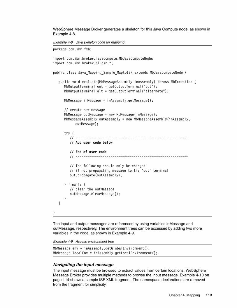
WebSphere Message Broker generates a skeleton for this Java Compute node, as shown in Example 4-8.
Example 4-8 Java skeleton code for mapping
package com.ibm.fxh;
import com.ibm.broker.javacompute.MbJavaComputeNode;import com.ibm.broker.plugin.*;
public class Java_Mapping_Sample_MaptoISF extends MbJavaComputeNode {
public void evaluate(MbMessageAssembly inAssembly) throws MbException {MbOutputTerminal out = getOutputTerminal("out");MbOutputTerminal alt = getOutputTerminal("alternate");
MbMessage inMessage = inAssembly.getMessage();
// create new messageMbMessage outMessage = new MbMessage(inMessage);MbMessageAssembly outAssembly = new MbMessageAssembly(inAssembly,
outMessage);
try {// ----------------------------------------------------------// Add user code below
// End of user code// ----------------------------------------------------------
// The following should only be changed// if not propagating message to the 'out' terminalout.propagate(outAssembly);
} finally {// clear the outMessageoutMessage.clearMessage();
}}
}
The input and output messages are referenced by using variables inMessage and outMessage, respectively. The environment trees can be accessed by adding two more variables in the code, as shown in Example 4-9.
Example 4-9 Access environment tree
MbMessage env = inAssembly.getGlobalEnvironment();MbMessage localEnv = inAssembly.getLocalEnvironment();
Navigating the input messageThe input message must be browsed to extract values from certain locations. WebSphere Message Broker provides multiple methods to browse the input message. Example 4-10 on page 114 shows a sample ISF XML fragment. The namespace declarations are removed from the fragment for simplicity.
Chapter 4. Mapping 113

Example 4-10 Sample ISF Fragment for navigation scenario
<isf:ISFMessage><Header>
<BusinessConcept>PAYMENT_ORIGINATION</BusinessConcept></Header><isf:CreditTransfer>
<ChargeBearer>DEBT</ChargeBearer><InstructedAmount Currency="USD">3.34</InstructedAmount>
</isf:CreditTransfer><Addenda />
</isf:ISFMessage>
Figure 4-15 shows navigating this XML document by using WebSphere Message Broker Java API.
Figure 4-15 Java logical message tree navigation
114 Financial Transaction Manager Technical Overview

There are five key methods to navigate the logical tree. Each of these methods returns an element that is called MbElement. Example 4-11 shows the method usage for an ISF document. The configuration data can be accessed from the environment tree in a similar way.
Example 4-11 ISF document navigation in Java
MbElement root = assembly.getMessage().getRootElement();MbElement isfRef = root.getLastChild().getFirstChild();MbElement header = isRef.getFirstChild();MbElement eBusinessConcept = header.getFirstChild();String businessConcept = eBusinessConcept.getValueAsString();
Additionally, XPath based methods can be used to navigate the message tree, as shown in Example 4-12.
Example 4-12 XPath based method for navigation
MbMessage msg = assembly.getMessage();List lstBC = (List)msg.evaluateXPath("/CreditTransfer/Header/BusinessConcept");MbElement eBusinessConcept = (MbElement)lstBC.get(0);String businessConcept = eBusinessConcept.getValueAsString();
Creating the output messageSimilar to access methods, WebSphere Message Broker provides element and attribute creation methods. These methods can be used to create elements in the output tree and set values. Example 4-13 shows adding a new header element RequestID to ISF.
Example 4-13 Creating an element in Java
MbElement requestID = header.createElementAsLastChild(MbXML.ELEMENT, "RequestID", "Some Value");
Elements and attributes also can be created by using XPath expressions. WebSphere Message Broker provides extension to XPath APIs to simplify the element creation process. Example 4-14 shows the creation of the element RequestID by using XPath API.
Example 4-14 Using XPath API to create an element
MbMessage msg = assembly.getMessage();msg.evaluateXPath(“/CreditTransfer/Header/?RequestID[set-value('Some Value')]”);
The ? before RequestID triggers the element creation rather than creating element access in the XPath extension.
Note: For a full list of XPath API extensions, click Developing message flow applications Transforming messages Using Java Writing Java Manipulating message body data Using XPath in WebSphere Message Broker information center.
Chapter 4. Mapping 115

XSLT mappingWebSphere Message Broker provides support for XSLT-based transformation by using a built-in node that is called XML Transformation node. The XMLTransformation node uses the XALAN-4J engine as it base. XSL-Transform node is built as a Java plug-in node. If it is working on the z/OS platform, processing can then be offloaded to the zAAP processor.
The node can be configured to pick up the stylesheet at design time by specifying XSLT path on the node or (at run time) by overriding LocalEnvironment tree values. For more information, see to the WebSphere Message Broker information center section Reference Message flow development Built-in nodes XSLTransform node Using local environment variables to set properties.
For runtime selection of stylesheets, the node can pick up the XSLT file from one of the following sources:
� Stylesheets on externally hosted server
The complete URL for the stylesheet can be provided in the LocalEnvironment tree, including the protocol to fetch the stylesheet; for example, http://url.to.my.server/xslt/abc.xsl. The WebSphere Message Broker run time must access this URL directly for the node to work correctly. This option is useful when there is a separate team building the transformation maps on a different server.
� Deployed to local file system
The stylesheets can be deployed to local or network file system that is accessible to WebSphere Message Broker. These stylesheets can then be accessed by the XSLTransform node either by absolute or relative path.
In case of absolute path, the stylesheets can be deployed to any location of choice. However, if a relative path is specified, WebSphere Message Broker resolves the root directory for XSLT files to <MQSI_WORKPATH>/XSL/external, where <MQSI_WORKPATH> is the directory that is defined by the MQSI_WORKPATH system environment variable. Thus, the stylesheet must be deployed to this location. WebSphere Message Broker run time throws an exception if it cannot locate the XSLT file.
The main advantage of this approach is that XSLT files are available to all the execution groups with single deployment. However, this approach complicates the back out process if deployment fails.
� Deployed to execution groups
Each execution group can host multiple stylesheets that can be accessed by XSLTransform nodes. You must add the stylesheet to a BAR file and deploy the BAR file to the execution group. Mentioned on the node property, stylesheets are picked up automatically by the BAR builder. The advantage of the use of deployed stylesheets is that the node manages them for you by backing out a deployment if things go wrong. The disadvantage is that you must deploy a copy of the stylesheets to each execution group that needs them.
Tip: To improve performance, cache the stylesheets that are fetched from the external server by using XSLTransform node capabilities. However, the only way to clear the cache when there are XSLT changes is to reload the run group or restart the broker.
116 Financial Transaction Manager Technical Overview

Map configuration access in XSLTXSLT can work with only a single XML input, which, by default, is the actual payload. It does not have access to the environment tree that holds the Financial Transaction Manager configuration. Thus, it is important to create a wrapper that consists of the Financial Transaction Manager configuration and payload information together. That wrapper can then be accessed by XSLT. Also, the output of XSLT must adhere to the end mapper v2 structural format. For more information about this format, see Chapter 5, “Using WebSphere Message Broker Toolkit to produce build artifacts” on page 131. You must put a compute node before the XSLTransform node to crate the wrapper structure, as shown in Figure 4-16.
Figure 4-16 XSLTransform node-based mapping flow
The configuration data structure is shown previously in Figure 4-10 on page 106 and Example 4-15. The compute node creates the structure that is similar to the structure that is shown in Example 4-15.
Example 4-15 Sample wrapper XML
<wrapper xmlns:cfg="http://www.ibm.com/xmlns/prod/ftm/MapConfig" xmlns:xsi="http://www.w3.org/2001/XMLSchema-instance" xmlns:isf="http://www.ibm.com/xmlns/prod/ftm/isf/v3"> <cfg:inboundCfg> <msgTypeCfg> <class>OC_101</class> <subType>BC_101</subType> <bat> <class>OC_101</class> <subType>ST_101</subType> </bat> <pt> <class>OC_101</class> <subType>ST_101</subType> </pt> <type>FIN101</type> </msgTypeCfg> ... </cfg:inboundCfg> <isf:ISFMessage> <Header> <BusinessConcept>PAYMENT_ORIGINATION</BusinessConcept> </Header> <isf:CreditTransfer> <ChargeBearer>DEBT</ChargeBearer> ... </isf:CreditTransfer> <Addenda /> </isf:ISFMessage> </wrapper>
Chapter 4. Mapping 117
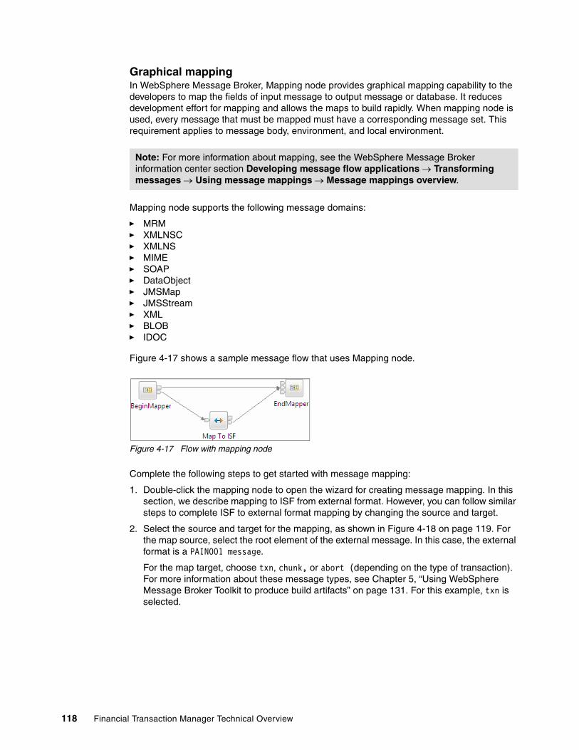
Graphical mappingIn WebSphere Message Broker, Mapping node provides graphical mapping capability to the developers to map the fields of input message to output message or database. It reduces development effort for mapping and allows the maps to build rapidly. When mapping node is used, every message that must be mapped must have a corresponding message set. This requirement applies to message body, environment, and local environment.
Mapping node supports the following message domains:
� MRM� XMLNSC� XMLNS� MIME� SOAP� DataObject� JMSMap� JMSStream� XML� BLOB� IDOC
Figure 4-17 shows a sample message flow that uses Mapping node.
Figure 4-17 Flow with mapping node
Complete the following steps to get started with message mapping:
1. Double-click the mapping node to open the wizard for creating message mapping. In this section, we describe mapping to ISF from external format. However, you can follow similar steps to complete ISF to external format mapping by changing the source and target.
2. Select the source and target for the mapping, as shown in Figure 4-18 on page 119. For the map source, select the root element of the external message. In this case, the external format is a PAIN001 message.
For the map target, choose txn, chunk, or abort (depending on the type of transaction). For more information about these message types, see Chapter 5, “Using WebSphere Message Broker Toolkit to produce build artifacts” on page 131. For this example, txn is selected.
Note: For more information about mapping, see the WebSphere Message Broker information center section Developing message flow applications Transforming messages Using message mappings Message mappings overview.
118 Financial Transaction Manager Technical Overview

Figure 4-18 Mapping node choose source and target
3. Click OK.
The WebSphere Message Broker toolkit creates a blank mapping template for you that is based on the source and target that is selected, as shown in Figure 4-19.
Figure 4-19 Mapping Editor
Next, complete the following steps to add an ISF document to the destination because this is an abstract structure:
1. Drag the tns1:Document element. Drag from the source panel into the wildcard element under xml (or the element that is specified in the mapping), as shown in Figure 4-20 on page 120.
Chapter 4. Mapping 119

Figure 4-20 Drag element to wildcard
2. The mapping editor prompts to choose the element as a substitution for the wildcard. Select the ISFMessage element, as shown in Figure 4-21, and then click OK.
Figure 4-21 Choose ISFMessage element
The WebSphere Message Broker toolkit creates a submap (with source as input message and destination as ISF), as shown in Figure 4-22. You can now drag to create the required mapping.
Figure 4-22 Submap editor
120 Financial Transaction Manager Technical Overview

WebSphere Transformation Extender based mappingA WebSphere Message Broker integration flow is required for inbound and outbound maps. These integration flows are supplied as part of the Financial Transaction Manager Package.
The WebSphere Transformation Extender maps that are provided with Financial Transaction Manager use configuration for some properties (such as validation option, business concept, and values for object SUBTYPE and OBJ_CLASS). This makes the maps more universally useful. At a minimum, the generic mapper flows require the configuration information to identify the WebSphere Transformation Extender map that is to run.
The generic flows that are provided for WebSphere Transformation Extender maps can also be configured to allow for custom subflows. These subflows can be started before or after the actual body mapping, pre-body mappers, and post-body mappers components. For more information about pre-body mappers and post-body mappers, see the Financial Transaction Manager information center by clicking Application programming Mappers WTX Mappers WTX Integration in FTM.
Unlike WebSphere Message Broker, WebSphere Transformation Extender does not have access to map configuration and output message domain details because Financial Transaction Manager configuration data is stored in the WebSphere Message Broker environment tree. The environment tree is not accessible inside WebSphere Transformation Extender map. Thus, this data must be explicitly passed to the WebSphere Transformation Extender map by using multiple input cards. Therefore, every WebSphere Transformation Extender map must have three input cards with the same name and sequence (Config, Source, and OutputMessageDomain), as shown in Figure 4-23.
Figure 4-23 WebSphere Transformation Extender input cards
These cards receive the following information:
� Config
Map configuration data. The inbound configuration allows the map to determine what sub_type and class must be put in ISF for an inbound message. Based on the inbound message format, the map should look up the configuration to obtain the values to be populated.
Note: Financial Transaction Manager requires a broker subflow for each map that can be started by Financial Transaction Manager. Use of these generic flows for WebSphere Transformation Extender maps removes the need to create a separate mapper subflow for each WebSphere Transformation Extender map.
Chapter 4. Mapping 121

Similarly, the outbound configuration allows the map to determine the outbound message format for a sub_type and class so that appropriate transformation map is chosen.
� Source
The actual body of the message.
� OutputMessageDomain
The body domain in which output message must be parsed.
The WebSphere Transformation Extender Map node for WebSphere Message Broker accepts multiple input cards by using the WebSphere Message Broker MessageCollection. For more information about this process, see the WebSphere Transformation Extender information center by browsing to WebSphere Transformation Extender for Integration Servers WebSphere Transformation Extender for Message Broker Developing a message flow Using the WTX Map node within a message flow Using the WTX Map node with a source map and multiple inputs.
Some message formats, such as Swift MT, consist of a common envelope that contains common message information (including message type and message body). The content of the message body depends on the message type. A common mapper construct for such formats (which are used by Swift MT maps that are provided with Financial Transaction Manager) is to have a common driver map that understands the envelope, performs mapping of any content in the envelope, and starts a separate run map that is specific to the message type that understands and maps the message body.
For the structure of the message that arrives on the config card of the map, XSD schemas are included with Financial Transaction Manager. These XSD schemas are for the XML configuration information document for inbound and outbound maps. The document structure allows for separate configuration information for different message types to be contained in a single document. Typically, the configuration document contains information to identify maps or submaps, set validation options, or provide values for the map to use. An example is the value to set for the business concept of resulting transactions. For more information about the structure of these configuration messages, see the Financial Transaction Manager information center section Application programming Mappers WTX Mappers WTX Integration in FTM WTX map configuration.
When the execution begins, the input data must first be validated to ensure that the data for each input conforms to the definition of the corresponding type tree that is mentioned in the input card. If invalid data is encountered, the map stops, unless you set a restart attribute when the input data is defined. When the restart attribute is set, WebSphere Transformation Extender continues parsing the input data even if it encounters errors. This feature is useful to detect all the errors in the input message. Use of the REJECT function when you are mapping the output data makes it possible to acquire the invalid data.
This mechanism also works for XML input data (by using the Xerces parser or a classic type tree). It is not applicable when reading XML with a direct XML Schema Definition (XSD) input card. That process is considered by using the XSD directly as a data definition. Because there is no type tree, the RESTART flag cannot be set.
Use of the Audit log feature permits the capture of validation errors on input or output. If some data does not meet the type tree definition (for example, if the type is not in a restriction list), it is displayed in the data log part of the audit log. The audit log is used by Financial Transaction Manager for error handling.
122 Financial Transaction Manager Technical Overview
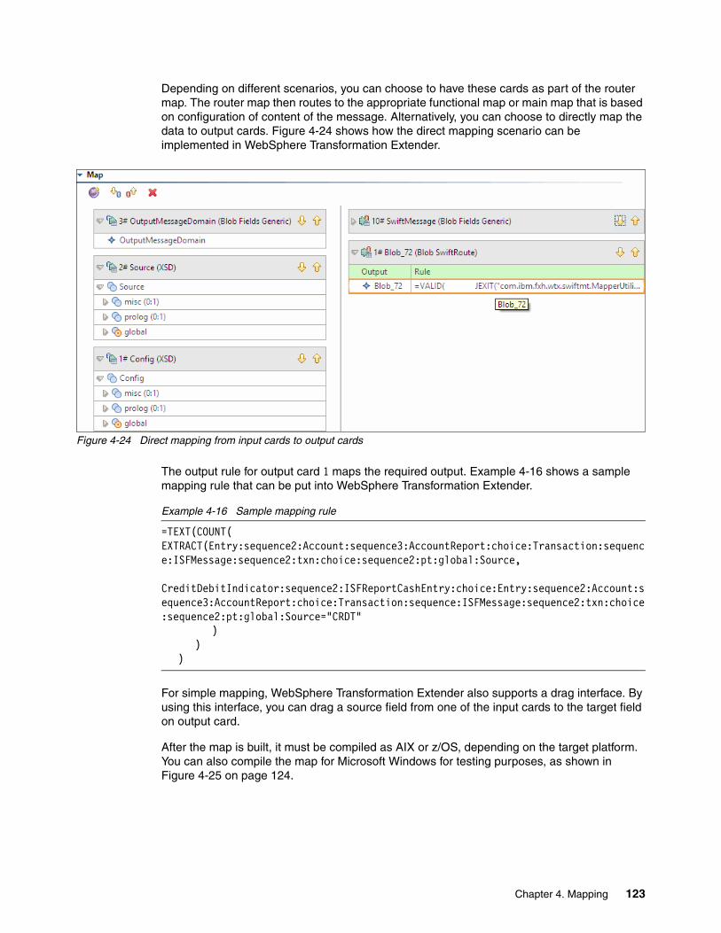
Depending on different scenarios, you can choose to have these cards as part of the router map. The router map then routes to the appropriate functional map or main map that is based on configuration of content of the message. Alternatively, you can choose to directly map the data to output cards. Figure 4-24 shows how the direct mapping scenario can be implemented in WebSphere Transformation Extender.
Figure 4-24 Direct mapping from input cards to output cards
The output rule for output card 1 maps the required output. Example 4-16 shows a sample mapping rule that can be put into WebSphere Transformation Extender.
Example 4-16 Sample mapping rule
=TEXT(COUNT(EXTRACT(Entry:sequence2:Account:sequence3:AccountReport:choice:Transaction:sequence:ISFMessage:sequence2:txn:choice:sequence2:pt:global:Source,
CreditDebitIndicator:sequence2:ISFReportCashEntry:choice:Entry:sequence2:Account:sequence3:AccountReport:choice:Transaction:sequence:ISFMessage:sequence2:txn:choice:sequence2:pt:global:Source="CRDT"
))
)
For simple mapping, WebSphere Transformation Extender also supports a drag interface. By using this interface, you can drag a source field from one of the input cards to the target field on output card.
After the map is built, it must be compiled as AIX or z/OS, depending on the target platform. You can also compile the map for Microsoft Windows for testing purposes, as shown in Figure 4-25 on page 124.
Chapter 4. Mapping 123
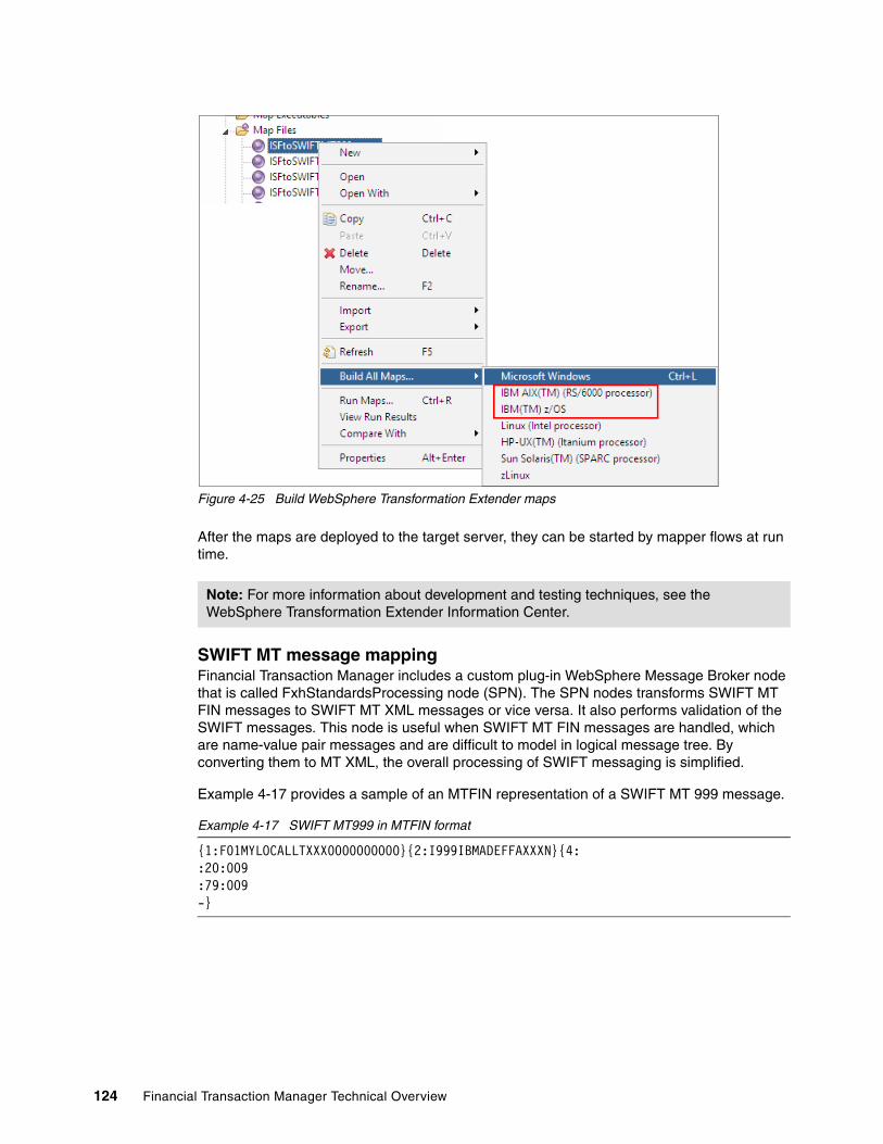
Figure 4-25 Build WebSphere Transformation Extender maps
After the maps are deployed to the target server, they can be started by mapper flows at run time.
SWIFT MT message mappingFinancial Transaction Manager includes a custom plug-in WebSphere Message Broker node that is called FxhStandardsProcessing node (SPN). The SPN nodes transforms SWIFT MT FIN messages to SWIFT MT XML messages or vice versa. It also performs validation of the SWIFT messages. This node is useful when SWIFT MT FIN messages are handled, which are name-value pair messages and are difficult to model in logical message tree. By converting them to MT XML, the overall processing of SWIFT messaging is simplified.
Example 4-17 provides a sample of an MTFIN representation of a SWIFT MT 999 message.
Example 4-17 SWIFT MT999 in MTFIN format
{1:F01MYLOCALLTXXX0000000000}{2:I999IBMADEFFAXXXN}{4::20:009:79:009-}
Note: For more information about development and testing techniques, see the WebSphere Transformation Extender Information Center.
124 Financial Transaction Manager Technical Overview

In this example, the output of FxhStandardsProcessing node is an MTXML representation of this SWIFT MT 999 message, as shown in Example 4-18.
Example 4-18 MTXML representation of SWIFT MT 999
<mtmsg:FinMessage xmlns:mt="urn:swift:xsd:fin.999.2011" xmlns:mtmsg="urn:swift:xsd:mtmsg.2011"> <mtmsg:Block1> <mtmsg:ApplicationIdentifier>F</mtmsg:ApplicationIdentifier> <mtmsg:ServiceIdentifier>01</mtmsg:ServiceIdentifier> <mtmsg:SessionNumber>0000</mtmsg:SessionNumber> <mtmsg:SequenceNumber>000000</mtmsg:SequenceNumber> <mtmsg:LogicalTerminalAddress>MYLOCALLTXXX</mtmsg:LogicalTerminalAddress> </mtmsg:Block1> <mtmsg:Block2> <mtmsg:InputIdentifier>I</mtmsg:InputIdentifier> <mtmsg:MessageType>999</mtmsg:MessageType> <mtmsg:MessagePriority>N</mtmsg:MessagePriority> <mtmsg:DestinationAddress>MYREMOTEXXXX</mtmsg:DestinationAddress> </mtmsg:Block2> <mtmsg:Block4> <mt:Document> <mt:MT999> <mt:F20a> <mt:F20>009</mt:F20> </mt:F20a> <mt:F79a> <mt:F79> <mt:Narrative> <mt:Line>009</mt:Line> </mt:Narrative> </mt:F79> </mt:F79a> </mt:MT999> </mt:Document> </mtmsg:Block4></mtmsg:FinMessage>
Each XML element of a message in this MTXML format belongs to one of the namespaces that are shown in Table 4-1.
Table 4-1 Namespaces for the MTXML Format Prefix Namespace XSD file description
Consider the following points concerning Table 4-1:
� In this table, mt is the message type to which the file applies; for example, 103 or 999.
Prefix Namespace XSD File Description
mtmsg urn:swift:xsd:mtmsg.year mtmsg.year.xsd This namespace represents the entire message.
mt urn:swift:xsd:fin.mt.year fin.mt.year.xsd This namespace represents the business data, which corresponds to FIN block 4. You can integrate the structure of the appropriate FIN message type into the message.
Chapter 4. Mapping 125

� In this table, year is the year of the SWIFTNet FIN message standard to which the file applies.
� As a result of this naming scheme, the name of the corresponding namespace changes with each new release of the SWIFTNet FIN message standard.
FxhStandardsProcessing node processingThe following steps show how this node processes:
1. The FxhStandardsProcessing node checks whether the result location of the message to be processed contains the element ComIbmDni.MsgStandardInfo.Domain. If this element contains the value DNIUNPARSABLE, the node performs no further processing and propagates the message on the failure terminal.
2. The FxhStandardsProcessing node checks the information from the request folder in LocalEnvironment. If no request data is available, the corresponding node property values are used.
3. If transformation or validation is to be done, the FxhStandardsProcessing node determines which message definition set is to be used. If the <ResultLocation>.ComIbmDni.MsgStandardInfo.DefinitionSet element is specified, the message definition set specified therein is used. Otherwise, the domain that is specified by the <ResultLocation>.ComIbmDni.MsgStandardInfo.Domain element is searched. Then, the most recently activated message definition set that corresponds to the message type of the input message is used.
4. If transformation or validation is to be done, the FxhStandardsProcessing node uses the message type that is specified for the message to determine which message definition is to be used.
5. If validation is to be done, the FxhStandardsProcessing node validates the message according to the message definition set determined in step 3.
6. If transformation is to be done, the FxhStandardsProcessing node determines the representation type of the input message. If the message body is provided by the Root.XMLNSC element, the FxhStandardsProcessing node assumes that the message is an MTXML message.
If the message body is provided by the Root.BLOB.BLOB element, the FxhStandardsProcessing node checks the first character of the body of the input message. If it is a left angle bracket (<), the message is assumed to be an MTXML message. Otherwise, the message is assumed to be an MTFIN message.
Error conditionsIf a processing error occurs and the failure terminal is connected, the Standards Processing node throws an exception and propagates the message to the failure terminal. Otherwise, the message is rolled back.
If an input message contains a non-well-formed XML message, the following process occurs:
� If the XML message is in the Root.XMLNSC element, this is treated as a processing error.
� If the XML message is in the Root.BLOB.BLOB element, the FxhStandardsProcessing node routes the message to its parseError terminal and does not throw an exception. The response folder of the message describes why the message was not parsed.
The following errors are caused by invalid input messages but are treated as parsing errors, not as exceptions:
� The input message is an MTFIN or MTXML message, but the time stamp (that is, the date and time when the message was created) of the message cannot be identified.
126 Financial Transaction Manager Technical Overview

� The message type cannot be identified.
4.3.3 Key deliverables
In this section, we describe artifacts that often must be produced as part of the mapping phase of the Financial Transaction Manager solution development. Consider this information a guideline for delivery. You can customize it to suit specific solution needs.
The following key deliverables are part of the mapping phase:
� Interface specification� Mapping specification� Message models� Mappers
Interface specificationThe interface specification provides a list of interfaces that the Financial Transaction Manager solution supports. It acts as a starting point for further deliverables and captures the following information:
� Protocol
Identifies the protocol that is going to be used for external message formats. In most cases, the protocol is WebSphere MQ, File, or Webservices. However, WebSphere Message Broker supports a various connectivity options. The protocol information is useful for the mappers to understand the protocol headers. For example, an WebSphere MQ RFH2 header can contain more technical information that must be carried throughout the transaction and sent to outbound interfaces.
� Formats
Identifies the data exchange formats that are used (ISO20022, Swift MT, custom, and so on). Knowing the exchange format helps identify if there is a need to build message models for formats that are not supplied with Financial Transaction Manager.
� Versions of formats
The formats keep evolving over time, and it is important to understand the exact version of the format that is used. Financial Transaction Manager might not support all the versions of a format. In such case, message models must be built to support a particular version.
� Message Type
Identify which message types are used by a particular interface (MT103, Pain.001.02, and so on).
Mapping specificationMapping design is the first step that is required to develop a mapper. This is a task often is performed by someone with a business analyst skill set. The result of the mapping design is a mapping specification.
Note: For more information about Standards Processing Node, see the Financial Transaction Manager information center by clicking Application programming Mappers Creating Mappers for FIN MT Messages FxhStandardsProcessing.
Tip: It is useful to have samples for each message type with which the solution might interface. It is easiest to acquire the sample message during the requirements gathering phase of the project.
Chapter 4. Mapping 127
A mapping specification should identify the source or target format and provide details of mapping content (element names, description, cardinality, structure, and so on).
A mapping specification should state whether the format represents a single transaction or multiple transactions. In the case of multiple transactions, it then provides details about how the structure of the message or file relates to the hierarchy of objects (BATCH and TRANSACTION related to the TRANSMISSION) in the Financial Transaction Manager data model that represents the message or file content.
The specification should provide details about values to populate columns in the Financial Transaction Manager tables and views.
The specification should provide mapping details for those elements in the message or file that should be mapped to the ISF content (path to element in ISF content and any relevant comments). This information should also include the direction on the handling of recurring structures or elements in the file or message. It should further include any details about conversion of data types, merging or splitting of fields, and mapping of code values.
Finally, the mapping specification should be supported by samples for the message or file and related ISF document (or endmapper document for an inbound mapping).
Financial Transaction Manager provides mapping specification for formats that are supported immediately. These specifications are available in the Financial Transaction Manager information center under Appendix J.
Message modelsMessage models are the basis of creating mappers. The message models can be delivered in the following forms, depending on the technology of choice:
� WebSphere Message Broker Message Sets� WebSphere Transformation Extender Type trees
For more information about these deliverables, see 4.3.1, “Parsing” on page 104.
MappersMappers are coding artifacts that map the two formats by using one or more options that are described in 4.3.2, “Mapping technologies” on page 109. These mappers must be included in the mapper flows that are described in Chapter 5, “Using WebSphere Message Broker Toolkit to produce build artifacts” on page 131.
128 Financial Transaction Manager Technical Overview

4.4 Handling large files
The processing of large files presents many challenges that can be best addressed at the design level instead of later during implementation. The following issues are particular to large files:
� Require much memory to parse into a logical tree� Create a large database unit of work during mapping� Force serialized processing during mapping
It is possible to address some of these issues to some degree at implementation time by using partial parsing with chunking and by making interim database commits. However, Financial Transaction Manager also supports a concept that is called Fragmentation, which can address these issues. For more information about handling large files, see the Financial Transaction Manager information center section Designing applications Design for large files.
Chapter 4. Mapping 129

130 Financial Transaction Manager Technical Overview

Chapter 5. Using WebSphere Message Broker Toolkit to produce build artifacts
Development in Financial Transaction Manager is done by using the WebSphere Message Broker Toolkit, which includes various different flows that are built by using the framework. This chapter describes the steps to set up workspace in WebSphere Message Broker Toolkit and the different types of message flows that must be built.
The following optional flows are available:
� Wrapper flows:
– Physical transmission wrapper– Event processing wrapper
� Action flows
� Mapper flows:
– Input mapper– Output mapper
� Emitter flows
� Heartbeat flows
Development cannot start before the analysis and design of the application is underway. The design task does not need to be fully completed. In fact, as the analysis and design are fleshed out, implementation of those artifacts can begin.
5
© Copyright IBM Corp. 2014. All rights reserved. 131

This chapter includes the following topics:
� Workspace setup� Wrapper flows� Action flows� Mapper flows� Emitter flows� Heartbeat flow� Message sets� Message flow templates� BAR files and deployment
132 Financial Transaction Manager Technical Overview

5.1 Workspace setup
The core components of Financial Transaction Manager are built by using WebSphere Message Broker Toolkit and are deployed to WebSphere Message Broker execution groups. In this section, we describe the steps that are used to set up the WebSphere Message Broker Toolkit workspace and typical layout of the projects and their references. However, you must set up the workspace that is based on the requirements and architecture for your project.
Complete the following steps to set up the workspace, import the Financial Transaction Manager core projects, and add the required references to the Financial Transaction Manager project:
1. Create a workspace and import the Financial Transaction Manager core component projects in the workspace. Although not mandatory, create a workspace for every Financial Transaction Manager project.
2. After the workspace is created, import the Financial Transaction Manager core components. Figure 5-1 shows the menu option that is available in the WebSphere Message Broker Toolkit for this task.
Figure 5-1 Import Projects menu
Chapter 5. Using WebSphere Message Broker Toolkit to produce build artifacts 133

After you make your selection, the WebSphere Message Broker Toolkit opens a wizard to import the projects, as shown in Figure 5-2.
Figure 5-2 Select Project Interchange
Financial Transaction Manager Core components for WebSphere Message Broker are delivered as project interchange (PI) compressed files that can be imported by using this wizard to recreate the required project structure.
3. Choose the PI for Financial Transaction Manager core components and import the projects. For more information about these steps, see the Financial Transaction Manager Information Center section, which is available by clicking Installing FTM installation Setting up FTM MQ and WebSphere Message Broker resources Installing message flows and message sets.
134 Financial Transaction Manager Technical Overview

4. After all of the required projects are imported, create a message broker or a message set project, as shown in Figure 5-3.
Figure 5-3 New Message Flow Project
5. To ensure that this new project can access Financial Transaction Manager core components, it is important to add reference to Financial Transaction Manager core projects for this message flow or message set project. Figure 5-4 shows the menu in WebSphere Message Broker Toolkit to perform this task.
Figure 5-4 Add project references
Chapter 5. Using WebSphere Message Broker Toolkit to produce build artifacts 135

This option shows the list of available projects in the workspace, as shown in Figure 5-5.
Figure 5-5 Project references
6. You must add the projects that are selected in Figure 5-5 as reference to the project. The other projects mainly use the SWIFT message processing capabilities of Financial Transaction Manager, which can be added if SWIFT processing is required. However, these projects use Standards Processing Node (SPN) which must be installed in the WebSphere Message Broker Toolkit. To install, complete the steps that are described in the Financial Transaction Manager Information Center section, which is available by clicking Installing FTM installation Setting up FTM MQ and WebSphere Message Broker resources Installing the FTM User-Defined nodes on the toolkit.
The message flow project that us created can now use core Financial Transaction Manager components for building various message flows.
5.2 Wrapper flows
The Financial Transaction Manager core processing engine consists of the following key components:
� Physical transmission flow: Manages the inbound message and starts mappers to transform them into ISF.
� Event processing flow: Manages events that are raised by various activities in Financial Transaction Manager.
These components are provided as WebSphere Message Broker subflows as part of Financial Transaction Manager. Therefore, it is essential to write wrappers around these flows by using wanted input and output transports.
136 Financial Transaction Manager Technical Overview

5.2.1 Physical transmission wrapper flow
All Financial Transaction Manager applications must have one or more physical transmission wrapper flows. These wrappers accept real-world input from defined interface transports, such as WebSphere MQ, File, and HTTP. They also provide control to physical transmission flow for processing. A physical transmission wrapper flow has the following key responsibilities:
� Manage channel identification� Manage and log failed messages� Provide a deployment point for inbound mappers� Record transport information� Process messages in burst mode
Figure 5-6 shows a sample physical transmission wrapper flow. Various aspects of this exampled flow are described in the following sections.
Figure 5-6 Example physical transmission flow
Naming convention and broker schemaTypically, all the physical transmission wrapper message flows are named PT_Wrapper_XXXXX.msgflow and are defined in the broker schema that is called PhysicalTransmissionFlow. This structuring allows the ESQL code in the flow to access ESQL constants and modules that are defined in the Financial Transaction Manager framework without any schema prefix.
Channel identificationThe responsibility of this part of the flow is to identify the Financial Transaction Manager channel for the inbound message. The channel features linked configuration that is used for the core flows to process the transaction. The subflow, which was shown in Figure 5-6, is an example that was created as part of the sample application and is not part of the Financial Transaction Manager core product. It is the responsibility of every physical transmission wrapper flow to decide the logic for deriving the channel information from the inbound transmission.
After the channel name is derived, the component must complete the following steps:
1. Load the channel configuration in the environment tree by using Financial Transaction Manager Cache API for channel. A possible API is shown in Example 5-1 on page 138.
Chapter 5. Using WebSphere Message Broker Toolkit to produce build artifacts 137

Example 5-1 Channel cache API
CREATE LASTCHILD OF Environment.PMP.Variables AS refChannel NAME 'Channel';CALL Cache.GetChannelByName(Cache.GetFlowInstanceCacheId(rEnv), Channel_Name, refChannel);
The channel configuration provides the label name of the mapper that is to be used to transform this message to ISF. The component should set this label in the LocalEnvironment tree to be picked up by the RouteToLabel node later. This value is available in Environment.PMP.Variables.Channel.MAPPER_NAME path.
2. If enabled, the component also must handle burst mode for the input messages, as described in “Burst mode” on page 139.
3. If there is any failure, such as invalid channel information or technical errors, the flow should route the control failed message processor section that is described in 9.1.6, “Process highlights” on page 274. This can be achieved by using a RouteToLabel node to route the control to the label that is attached to the failed message processor.
Physical transmission subflowThe physical transition subflow is part of the Financial Transaction Manager core components and provides capabilities to log physical transmission, start ISF mapper, and raise necessary events. (For more information about this subflow, see the Financial Transaction Manager Information Center.) The subflow provides an output terminal that should be connected to an MQOutput node to put message to the event queue. The MQOutput node acts as input to an event processing wrapper flow that is described in 5.2, “Wrapper flows” on page 136.
Mappers subflowsThe physical transmission flow gives control to one of the inbound mapper flows to map the custom format to ISF. These mapper flows must be included in this wrapper flow. Typically, a parent-level subflow (called a container flow), is created and added to the physical transmission flow. This container flow holds various mapper subflows. The subflow, which is indicated by label 3 in Figure 5-6 on page 137, is an example of a container flow that contains multiple subflows for various mappers.
Failed message processingWhen something goes wrong in the physical transition wrapper flow, the control is passed to the label of the failure processing flow that can send it to a failure queue. However, the use of this approach is optional. Different solutions can follow different error handling strategies. Therefore, the failed message processing part is driven by project requirements and is not a part of the Financial Transaction Manager core components.
In addition to these four aspects of the physical transmission flow, the following optional aspects must be considered:
� Transport level information� Burst mode
Note: For more information about the cache APIs that are available in Financial Transaction Manager, see the Financial Transaction Manager Information Center by browsing to Application programming Static Data Cache.
138 Financial Transaction Manager Technical Overview

Transport level informationBy default, the physical transmission subflow uses information from the WebSphere MQ header to log certain attributes of the physical transmission records to the database (such as UID), which is populated from MQMD.MsgId by default. If the inbound transport is anything other than WebSphere MQ, or the default header values must be overridden, the physical transmission flow has a responsibility of specifying or overriding the values that are logged in the Financial Transaction Manager operational database against the physical transmission. These values are set in the environment tree (under Environment.PMP.Variables.LogPT.DBRecord for a single transmission or under Environment.PMP.Variables.LogFRAG.DBRecord for fragments) by the physical transmission flow. The physical transmission flow typically uses the compute node and ESQL code for the specification or overriding of values before passing the control to PhysicalTransmissionFlow subflow.
For more information about the values that must be set, see the Financial Transaction Manager Information Center by clicking Application programming Physical Transmission Wrapper Physical Transmission Flow Persistence API.
Burst modeBy using burst mode, batch processing efficiencies can be used for single transaction processing use cases. Aggregating events that relate to a group of single transactions reduces overhead because there are fewer database and WebSphere MQ commit calls.
Burst mode can be enabled on any input channel where it is possible to proactively get the next message from within a message flow. For example, when WebSphere MQ is used as an input, the physical transmission flow is driven by an MQInput node. After processing the WebSphere MQ message, it is possible to return and get the next message by using an MQGet node. By using this technique, the physical transmission flow can get and process a group of single messages in the same unit of work. Doing this allows the Send Event API call to aggregate these events where possible.
To enable burst mode for a channel, the following tasks must be completed:
� Implement a transmission wrapper that is burst mode aware� Include burst mode settings on the channel definition� Review event metadata as part of a design for aggregation
Figure 5-7 on page 140 shows an example of a transmission wrapper that supports burst mode.
Chapter 5. Using WebSphere Message Broker Toolkit to produce build artifacts 139
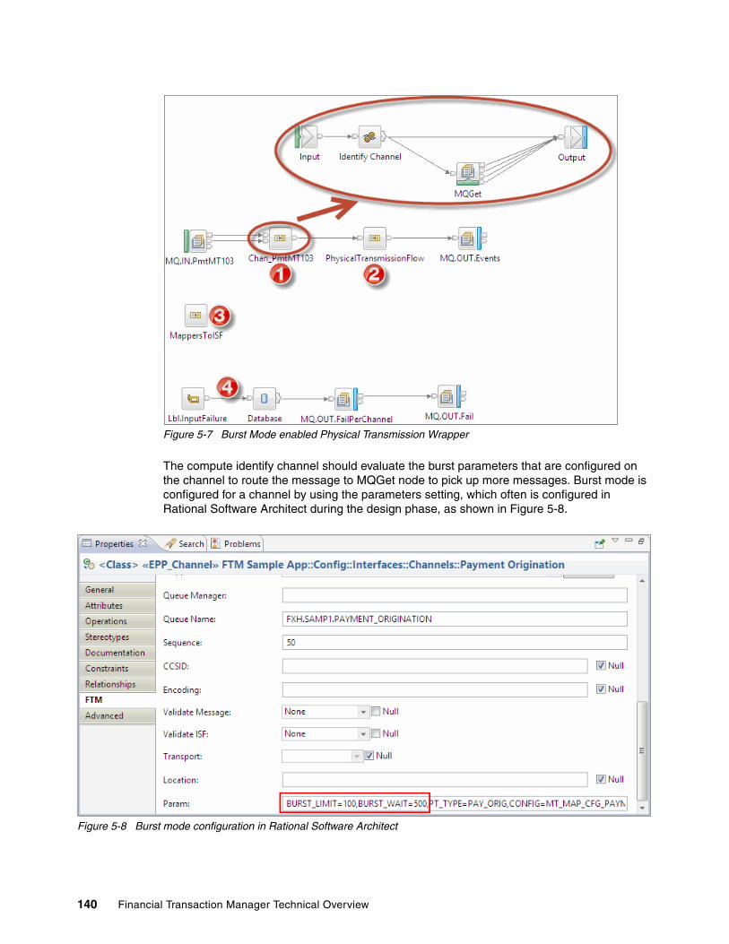
Figure 5-7 Burst Mode enabled Physical Transmission Wrapper
The compute identify channel should evaluate the burst parameters that are configured on the channel to route the message to MQGet node to pick up more messages. Burst mode is configured for a channel by using the parameters setting, which often is configured in Rational Software Architect during the design phase, as shown in Figure 5-8.
Figure 5-8 Burst mode configuration in Rational Software Architect
140 Financial Transaction Manager Technical Overview

Table 5-1 shows the settings that are supported for burst mode.
Table 5-1 Burst mode settings
For more information, see the Financial Transaction Manager Information Center section by clicking Application programming Physical Transmission Wrapper Burst mode.
5.2.2 Event processing wrapper flow
The event processing wrapper flow provides input and output queue points to the Financial Transaction Manager event processing component and associated failures. EventProcessingFlow subflow is part of core the Financial Transaction Manager product, which is responsible for processing events that are raised by various components. Figure 5-9 shows a sample event processing wrapper flow.
Figure 5-9 Event processing wrapper message flow
As part of the event processing, Financial Transaction Manager run actions that are associated with transitions. These actions are implemented as subflows (as described in Section 5.3, “Action flows” on page 142). The event processing wrapper also acts as a container for these action subflows. Also, the actions can route the control to outbound mappers for sending a request to an external system. These outbound mappers are also included in this subflow so that they are accessible to the action flows.
Parameter Name Description
BURST_LIMIT The maximum number of messages to read in a unit of work.
BURST_WAIT The maximum time, in milliseconds, to wait for the next message.
Important: When burst mode is used, all of the messages in the single burst are processed in a single unit of work. Therefore, if one of the messages fails during processing, the entire batch is rolled back unless explicit commits are issued. Therefore, transaction boundaries must be defined carefully when burst mode is used.
Note: Burst mode might not be suitable for all input channels. Consider the business case that is served on a channel in specific relation to latency of processing response. Some channels might receive a few messages that are spread over a whole day, while other channels might be subject to periodic bursts of messages.
Chapter 5. Using WebSphere Message Broker Toolkit to produce build artifacts 141

Typically, a parent level subflow is created and added to an event processing wrapper flow. This parent subflow holds various action subflows. The subflow that is indicated in Figure 5-9 on page 141 is an example of a parent wrapper flow that contains multiple subflows for various actions and outbound mappers.
Similar to physical transmission wrapper flow, exception handling strategy is driven by requirements. The example that is shown in Figure 5-9 on page 141 sends failed events to the failure queue by default.
The EventProcessingFlow subflow, which is part of core Financial Transaction Manager components, has two input terminals that are named Propagate Input and Main Input. The propagate input terminal is used by PhysicalTransmissionFlow that is described in 5.2.1, “Physical transmission wrapper flow” on page 137 to process events internally. The event processing wrapper flow should always use the Main Input terminal.
The MQOutput node, which is named EVENTS OUT, puts the message on the same queue as that of input queue when an event is raised by the action subflow (as described in 5.3, “Action flows” on page 142) and the RENDER_AS_MSG attribute of the event is set.
5.3 Action flows
As part of the Finite State Machine creations, actions are defined as a result of state transition. These actions are implemented as subflows in WebSphere Message Broker.
There is a standard template for action subflows; they must start with the BeginAction subflow and end with the EndAction subflow. In between these start and end flows, any arrangement of message broker nodes is possible, including the decision service node that was introduced in Financial Transaction Manager 2.1. A single compute node is sufficient to be put between these two subflows for processing to implement the required logic.
The BeginAction subflow is a single property under Financial Transaction Manager folder that is called Label name. The value of this label must match the action name that is mentioned in the Finite State Machine.
The EndAction subflow returns the control back to the event processing flow for further processing and stops propagation of the message further in this subflow.
Figure 5-10 shows a typical action subflow implementation where the action is implemented by using ESQL code in a compute node.
Figure 5-10 Action subflow implementation
142 Financial Transaction Manager Technical Overview

5.3.1 Coding actions
Within the action implementation, there is much information available in the message body or in the environment tree; of particular interest is Environment.PMP.Variables.Transition[].TransObjects.Object[], which contains the selected columns for the object that is affected by the event. The other main source of information is held in the event that caused the transition. This is held in the environment and should be indirectly referenced by using a locally defined REFERENCE variable that is started by the following function:
Actions.CurrentEvent(INOUT rEnv REFERENCE)
Because of possible event aggregation or other object selectors that return multiple objects, the action can be called to act upon multiple objects. Therefore, you can code actions for multiple objects. Example 5-2 shows a sample skeleton for coding actions for multiple objects.
Example 5-2 Sample skeleton for coding actions
CREATE FUNCTION Main() RETURNS BOOLEANBEGIN
DECLARE refTransition REFERENCE TO Environment.PMP.Variables.Transition[Environment.PMP.Variables.IterationCount];
DECLARE refObj REFERENCE TO refTransition.TransObjects.Object[1];
WHILE LASTMOVE(refObj) DO-- ESQL Code to Perform Action on Object.
MOVE refObj NEXTSIBLING REPEAT NAME;END WHILE;
RETURN TRUE;END;
The exceptions in the action subflow are not handled by BeginAction or EndAction subflow. Instead, they propagate back to the event processing flow where they are handled by using generic error flow. In such a case, the generic error flow raises an E_UnexpectedError event and rolls back all other database operations within that unit of work.
Raising eventsThere might be cases where action implementation wants to raise events to cause further Finite State Machine transitions. Financial Transaction Manager provides the following simplified ESQL APIs to raise events:
� CreateEvent: Builds an event message at a specified message location. � SendEvent: Called to send a fully built event message.
Important: When the SendEvent function is called, the event is not sent immediately, but is added to an event cache in the environment tree for processing. At the end of processing the current action, all the events in the event cache are analyzed to see whether any of the events can be aggregated to improve performance and are processed accordingly. Additionally, events with RENDER_AS_MSG set are sent back to the event queue.
Chapter 5. Using WebSphere Message Broker Toolkit to produce build artifacts 143

Financial Transaction Manager provides other helper functions to combine the processing of the two functions, CreateEvent and SendEvent. For more information about these APIs, see the Financial Transaction Manager Information Center by clicking Application programming Instrumentation and Trace API.
Access to ISF in actionISF data can be made available to the action by specifying the ISF_DATA column on the transition object selector (by using master selector or override). This data is stored as a CLOB in the database and must be parsed by using the ESQL CREATE PARSE statement to be accessible in the action.
It is recommended to parse ISF tree into the local environment instead of the environment. This is because memory that is associated with parsers in the environment is not freed until the flow ends. Memory that is associated with parsers in other areas, such as the local environment, can be freed by using the ESQL DELETE FIELD command, where memory is released on exit from the flow node. This is important when you are dealing with large batches where injudicious coding can lead to a many unnecessary parsers that are occupying message broker memory resources.
Update ISF in actionIf the action updates the ISF, it must also update the ISF_DATA column of the transaction record. To do this, the ISF message tree, which is a parsed version of the ISF, first must be written to a bitstream, as shown in Example 5-3.
Example 5-3 Converting ISF to bitstream
SET isfBlob = ASBITSTREAM(LocalEnvironment.PMP.ISF.XMLNSC SET Common.MessageSet('ISF') );
The ISF_DATA column of the TRANSACTION table can then be updated with the isfBlob value by using helper ESQL functions that are provided by Financial Transaction Manager. For more information about these functions, see the Financial Transaction Manager Information Center by clicking Application programming Actions Database Persistence Persistence ESQL API.
5.3.2 Database persistence
The logic in an action subflow often must create outbound transactions, physical transmissions, and batch objects. Before Financial Transaction Manager V2.1, creating these objects was done by using a PASSTHRU statement in ESQL to insert a single record at a time in the Financial Transaction Manager database. Because the action subflow can work on multiple transaction objects at a time, multiple insert queries are run against the database with data differences. These insert queries might not be optimal from a performance perspective. Since V2.1, Financial Transaction Manager introduces a Persistence API that can insert multiple database rows in a single PASSTHRU call.
The use of Persistence APIs provides the following benefits:
� Abstraction from database-specific syntax
� Configurable control of the rows per insert
� Configurable control of the number of rows to cache in memory
Attention: Selecting ISF data in action has performance implications. Therefore, every attempt should be made to avoid selection of ISF data in action implementation.
144 Financial Transaction Manager Technical Overview

� Ability to insert by using the insertable views
� Ability to insert direct to the tables
� Full Financial Transaction Manager instrumentation of all SQL that is issued through the API
� Trace of SQL errors, including SQL state and error codes
For more information about APIs, see the Financial Transaction Manager Information Center by clicking Application programming Actions Database Persistence.
5.4 Mapper flows
Mapper flows are WebSphere Message Broker subflows that plug in the mapping artifact that you created in Financial Transaction Manager. These mapping artifacts are described in Chapter 4, “Mapping” on page 85. You can create the following types of mapper flows:
� Input mapper to transform external message format into ISF� Output mappers to transform ISF to external message format
5.4.1 Input mapper
Input mappers are built by using a pattern. They must start with a subflow that is called BeginMapper and end with the EndMapper subflow, as shown in Figure 5-11.
Figure 5-11 Typical Input mapper flow
The BeginMapper subflow also has exception handling capabilities as described later in this section. For it to work correctly, the failure terminal of the BeginMapper node should be connected directly to the EndMapper node terminal where the successfully mapped message is propagated.
Between these two subflows, any combination of nodes that are available in WebSphere Message Broker can be used for transformation. Additionally, for mapping SWIFT MT message to ISF, Standards Processing Node (SPN) can be used to validate and transform the SWIFT MT message to SWIFT MT XML format for easier mapping. For more information about SPN processing, see Chapter 4, “Mapping” on page 85.
The BeginMapper node contains a property under Financial Transaction Manager folder that is called Label Name. This value of this property must be same as the value that is configured on Financial Transaction Manager channel in configuration database.
Attention: Inserting multiple rows by using persistence APIs is not available on z/OS at the time of this writing.
Chapter 5. Using WebSphere Message Broker Toolkit to produce build artifacts 145

The EndMapper subflow has the following main responsibilities:
� Store the mapped transactions, batches, mapping errors (if any) to the Financial Transaction Manager database.
� Raise predefined mapping events to indicate the following information:
– Mapping success– Mapping failed or was ended for any reason.
� Return control to the main physical transmission flow for further processing.
All inbound mappers should complete with one of the following results:
� Success: Mapping is completed with no known errors.
� Failure: Mapping completed, but some errors were encountered. The processing in this case is similar to the success scenario. However, EndMapper subflow raises a different event to indicate the failure status.
� Aborted: Mapping failed and transaction processing cannot continue. This status is set by the exception handling part of the BeginMapper subflow that are described later in this section.
EndMapper subflow has three input terminals. The first terminal is for using End Mapper Version 1 and other two terminals are for End Mapper version 2. The features and benefits of both versions are described next.
EndMapper version 1EndMapper version 1 (V1) is a part of older, traditional implementations in which ISF is propagated as OutputRoot and other column persistence information that is passed in the WebSphere Message Broker environment. This version is deprecated for most of the use cases and should be used only when the earlier code is migrated.
Database persistenceEndMapper is responsible for persisting all transactions and batches that are mapped into ISF. In certain scenarios, there might be a requirement to store more information about a transaction, such as database extensions. In such cases, the EndMapper provides an environment tree-based interface for persisting more values in the Financial Transaction Manager database. The root location for this API is Environment.PMP.Variables.MapDBData. It is the responsibility of the mapper implementation to set the appropriate values under this path. It supports persistence of the following objects and their properties:
� Transmissions� Fragments� Batches� Transactions (Batch)� Transactions (Non-Batch)� Securities Transactions� Payment Transactions
For more information about the location of each object and its supported properties, see the Financial Transaction Manager Information Center by clicking Application programming Mappers Input Mappers Input Mapper Subflows EndMapper (v1) Data Persistence Interface.
146 Financial Transaction Manager Technical Overview
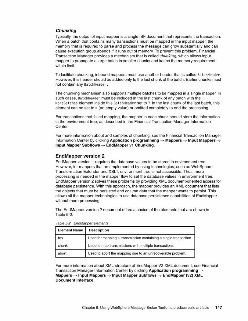
ChunkingTypically, the output of input mapper is a single ISF document that represents the transaction. When a batch that contains many transactions must be mapped in the input mapper, the memory that is required to parse and process the message can grow substantially and can cause execution group abends if it runs out of memory. To prevent this problem, Financial Transaction Manager provides a mechanism that is called chunking, which allows input mapper to propagate a large batch in smaller chunks and keeps the memory requirement within limit.
To facilitate chunking, inbound mappers must use another header that is called BatchHeader. However, this header should be added only to the last chunk of the batch. Earlier chunks must not contain any BatchHeader.
The chunking mechanism also supports multiple batches to be mapped in a single mapper. In such cases, BatchHeader must be included in the last chunk of any batch with the MoreBatches element inside this BatchHeader set to Y. In the last chunk of the last batch, this element can be set to N (an empty value) or omitted completely to end the processing.
For transactions that failed mapping, the mapper in each chunk should store the information in the environment tree, as described in the Financial Transaction Manager Information Center.
For more information about and samples of chunking, see the Financial Transaction Manager Information Center by clicking Application programming Mappers Input Mappers Input Mapper Subflows EndMapper v1 Chunking.
EndMapper version 2EndMapper version 1 requires the database values to be stored in environment tree. However, for mappers that are implemented by using technologies, such as WebSphere Transformation Extender and XSLT, environment tree is not accessible. Thus, more processing is needed in the mapper flow to set the database values in environment tree. EndMapper version 2 solves these problems by providing XML document-oriented access for database persistence. With this approach, the mapper provides an XML document that lists the objects that must be persisted and column data that the mapper wants to persist. This allows all the mapper technologies to use database persistence capabilities of EndMapper without more processing.
The EndMapper version 2 document offers a choice of the elements that are shown in Table 5-2.
Table 5-2 EndMapper elements
For more information about XML structure of EndMapper V2 XML document, see Financial Transaction Manager Information Center by clicking Application programming Mappers Input Mappers Input Mapper Subflows EndMapper (v2) XML Document Interface.
Element Name Description
txn Used for mapping a transmission containing a single transaction.
chunk Used to map transmissions with multiple transactions.
abort Used to abort the mapping due to an unrecoverable problem.
Chapter 5. Using WebSphere Message Broker Toolkit to produce build artifacts 147

Inbound mapper error handlingThe inbound mapper can encounter expected or unexpected errors. In such cases, it is important to log the error message to the Financial Transaction Manager database and raise events to indicate failure. BeginMapper subflow provides an exception handling mechanism that allows handling of such an exception in a consistent manner.
When it detects any exception, the subflow sets the mapping status to abort and then propagates the message to the failure terminal (which should be connect to EndMapper subflow) or throws again the exception to the physical transmission flow for processing.
5.4.2 Output mappers
The output mappers are called for as Finite State Machine actions. They are responsible for mapping ISF transaction documents to an outbound physical transmission in the form of a single transaction, batch, or fragment.
Output mappers are responsible for mapping ISF transaction documents to an outbound physical transmission in the form of a single transaction, batch, or fragment. They always start with the BeginOutboundMapper subflow and end with the EndOutboundMapper subflow that is provided as part of Financial Transaction Manager components, as shown in Figure 5-12. The failure terminal of the BeginOutboundMapper node must be connected directly to the EndOutboundMapper node to allow error processing.
Figure 5-12 Typical output mapper flow
The BeginOutboundMapper subflow has the following main responsibilities:
� Set the value in Label Name property. The subflow has a property that is called Label Name under the Financial Transaction Manager folder that must be set to a value that matches the name of a specific mapper that is configured in the configuration database.
� Fetch the ISF document. This can be done from ISF cache or from Financial Transaction Manager database. The ISF document is parsed (if not already) before giving it to the actual mapper. However, this behavior can be overridden to avoid fetching ISF in the BeginOutboundMapper subflow. This feature is useful when a batch of transactions is mapped, which can result in multiple ISF documents being fetched and increasing the memory requirement.
� Handle any errors that are thrown by the mapper and set the mapping status to aborted.
The EndOutboundMapper subflow has the following main responsibilities:
� Serialize the logical tree for the physical message that can be sent to end systems.
� Update the physical transmission data in the database with this bitstream.
� Raise various mapper events.
� Return control to the main event processing flow to complete processing of the event that is processed.
148 Financial Transaction Manager Technical Overview

For more information, see the Financial Transaction Manager Information Center by clicking Application programming Mappers Output Mappers.
5.5 Emitter flows
Events in Financial Transaction Manager can be configured to be external with a specific topic by using the Publish-Subcribe feature of WebSphere Message Broker and WebSphere MQ. The purpose of the emitter flow is to create the contents of the message that can be published externally. Similar to action subflow, the emitter flows follow a template pattern that begins with a BeginPublish subflow and end with the EndPublish subflow. A single compute node often is used to write the logic for the emitter flow. However, any combination and number of nodes that are available in WebSphere Message Broker can be used.
Figure 5-13 shows a typical emitter flow implementation.
Figure 5-13 Typical event emitter flow
The BeginPublish subflow provides a label that should be set to a value that is mentioned in the emittername property of the external event in the Finite State Machine.
The responsibility of the EndPublish subflow is to return control to send the external event for publishing.
For more information about External Event publication capabilities of Financial Transaction Manager and emitter flows, see Financial Transaction Manager Information Center by clicking Application programming External Event Publishing.
5.6 Heartbeat flow
During transaction processing, there might be requirements to perform time-based processing rather than having an external event, such as the following examples:
� Future dated payment processing� Enable or disable processing in certain time windows� Monitoring timeouts from the system
Such requirements can be achieved in Financial Transaction Manager by using a heartbeat flow. The flow is implemented by using timer nodes that are provided in WebSphere Message Broker. A sample heartbeat flow is provided with Financial Transaction Manager for reference.
The heartbeat flow raises the following events:
� E_HeartbeatStart: This should be raised when the heartbeat flow starts for the first time. This event is useful to trigger recovery operations if a broker restarts.
� E_Heartbeat: This event should be raised later at predefined intervals.
Important: All output mapper subflows must be deployed as part of the message flow that starts the mapping, which often is an event processing wrapper.
Chapter 5. Using WebSphere Message Broker Toolkit to produce build artifacts 149

These events should have the current time in the event context that can be used in the event filter expression in the Finite State Machine to transition objects selectively.
For more information, see the Financial Transaction Manager Information Center by clicking Application programming Heartbeat.
5.7 Message sets
Message sets in WebSphere Message Broker provide the structural layout for inbound and outbound messages and for internal Financial Transaction Manager messages, such as ISF and End Mapper v2 structures. Financial Transaction Manager includes message sets for all the internal formats. However, when you are dealing with external formats, it is important to create a message set to represent the message and add its reference to the message flow project. For more information about the steps to create a message set, see the WebSphere Message Broker information center by clicking Developing message flow applications Constructing message models, and Chapter 4, “Mapping” on page 85 and “WebSphere Message Broker message sets” on page 105.
5.8 Message flow templates
All the message flows that were described in this chapter follow a template pattern for development. To further simplify the development and maintain consistency in the way message flows are developed, FTM provides templates for all these message flows. These message flows are packaged in a separate project and project interchange that can be imported in the workspace. Figure 5-14 shows the layout of the template project.
Figure 5-14 Template project structure
Each broker schema contains flows and a corresponding ESQL template that can be pasted into your project as a starting point. The ESQL code includes all of the best practices that we described in this chapter. It is also recommended that the same broker schema names are used in your projects.
Important: Pay attention to the number of instances that are deployed for this message flow because each instance raises its own events, which can result in large number of events being raised.
150 Financial Transaction Manager Technical Overview

5.9 BAR files and deployment
A BAR file is a container for deploying message flows that are developed in WebSphere Message Broker. Because most of the Financial Transaction Manager core components are provided are subflows, a few flows can be deployed without any reference to an application. The following flows can be deployed in the context of an application:
� Physical transmission wrapper flows: One or more per application.� Event processing wrapper flows: One per application.� Message sets: Contains ISF and other custom message sets.� Heartbeat flows: Triggers time-based event, if required.
The packaging of these flows in BAR files depends on the non-functional and scalability requirements of the solution. Regardless of the requirement, it is recommended to start small with all the message flows in a single BAR file and deploy to a single execution group, as shown in Figure 5-15.
Figure 5-15 Small step deployment
The performance of the solution then needs to be measured against the following information:
� Transaction throughput� CPU usage� Latency� Memory usage
There are various instrumentation points within Financial Transaction Manager and WebSphere Message Broker that can provide a view on these factors per component. These components can then be split into multiple execution groups or multiple brokers, depending on WebSphere Message Broker deployment topology to achieve the required non-functional requirements.
Important: Deployment of PhysicalTransmissionWrappers and EventProcessingWrappers on separate execution groups need multiple deployments of message sets to both of the execution groups. Consideration should be given to increasing memory requirements because of this aspect while scaling.
Chapter 5. Using WebSphere Message Broker Toolkit to produce build artifacts 151

152 Financial Transaction Manager Technical Overview

Chapter 6. User interface
In this chapter, we describe the Financial Transaction Manager user interface and how business and technology users can use it.
For business users, we describe how to monitor, report, and search on transactions that are being processed or completed processing. We also describe how to handle transactions that require user intervention and how to monitor and resolve alerts.
For technology users, we describe how to use the Financial Transaction Manager user interface to configure a solution to define interfaces, calendars, and schedules. We also explain how to configure system variables that can affect transaction processing and how the user interface displays data to the user.
This chapter includes the following topics:
� Introduction to the user interface� Financial Transaction Manager applications� Working with operational data� Configuring Financial Transaction Manager
6
© Copyright IBM Corp. 2014. All rights reserved. 153

6.1 Introduction to the user interface
The Financial Transaction Manager Operations and Administration Console is the primary application that you use to monitor and manage transactions and configure the solution. It is a thin client application that is deployed in IBM WebSphere Application Server and accessible through a web browser. Figure 6-1 shows the Operations and Administration Console and menu items.
Figure 6-1 Operations and Administration Console Welcome window
The Operations and Administration Console is divided into the following main areas:
� Favorites
Frequently used, user-defined queries.
� Operational Data
Functions that are used to interact with operational transactional data and events.
� Configuration Data
Functions that are used to configure the solution.
By using the items that are under these categories, you can complete the following tasks:
� Monitor transactions and interfaces
Query the status of transactions as they are being processed and interfaces to ensure that they are operating as expected.
� Manage transactions and alerts
Interact with transactions and alerts to take actions, such as releasing payments and acknowledging alerts.
154 Financial Transaction Manager Technical Overview
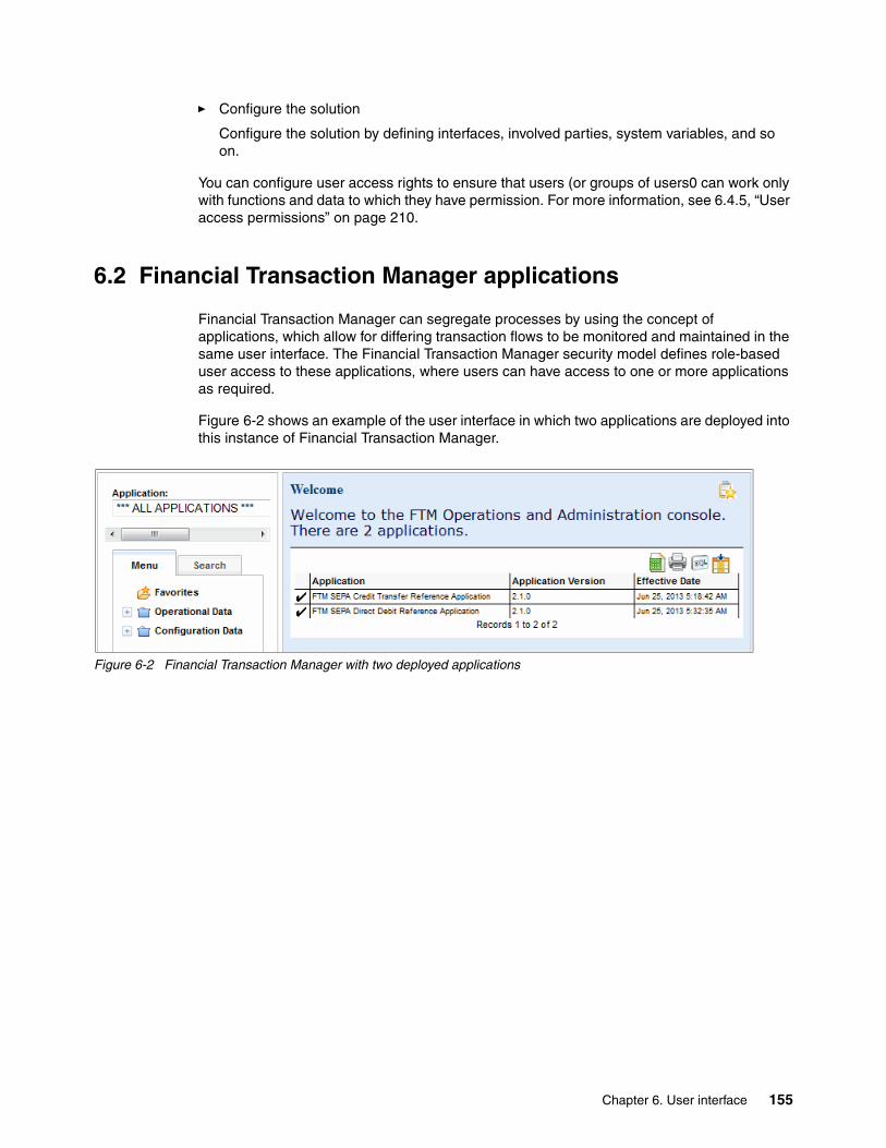
� Configure the solution
Configure the solution by defining interfaces, involved parties, system variables, and so on.
You can configure user access rights to ensure that users (or groups of users0 can work only with functions and data to which they have permission. For more information, see 6.4.5, “User access permissions” on page 210.
6.2 Financial Transaction Manager applications
Financial Transaction Manager can segregate processes by using the concept of applications, which allow for differing transaction flows to be monitored and maintained in the same user interface. The Financial Transaction Manager security model defines role-based user access to these applications, where users can have access to one or more applications as required.
Figure 6-2 shows an example of the user interface in which two applications are deployed into this instance of Financial Transaction Manager.
Figure 6-2 Financial Transaction Manager with two deployed applications
Chapter 6. User interface 155
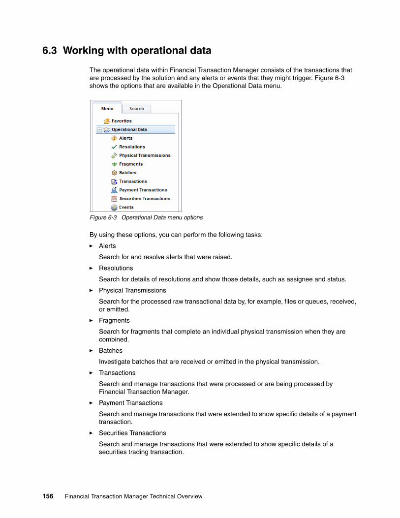
6.3 Working with operational data
The operational data within Financial Transaction Manager consists of the transactions that are processed by the solution and any alerts or events that they might trigger. Figure 6-3 shows the options that are available in the Operational Data menu.
Figure 6-3 Operational Data menu options
By using these options, you can perform the following tasks:
� Alerts
Search for and resolve alerts that were raised.
� Resolutions
Search for details of resolutions and show those details, such as assignee and status.
� Physical Transmissions
Search for the processed raw transactional data by, for example, files or queues, received, or emitted.
� Fragments
Search for fragments that complete an individual physical transmission when they are combined.
� Batches
Investigate batches that are received or emitted in the physical transmission.
� Transactions
Search and manage transactions that were processed or are being processed by Financial Transaction Manager.
� Payment Transactions
Search and manage transactions that were extended to show specific details of a payment transaction.
� Securities Transactions
Search and manage transactions that were extended to show specific details of a securities trading transaction.
156 Financial Transaction Manager Technical Overview

� Events
Search for events that were processed, which often are technical events, such as heartbeat events and scheduled events.
The common functions that can be performed with Operational Data include searching for transactions and physical transmission, finding the state of the object, and resolving or taking actions on transactions and alerts that require user intervention, for example, authorizing a payment.
Transactions are represented by the following different but inter-related objects within Financial Transaction Manager:
� Physical Transmission
The raw data that is received or transmitted.
� Fragments
Two or more pieces of raw data that complete a physical transmission when they are combined.
� Batch (if present)
A collection of transactions.
� Transaction
An individual transaction.
� Extended Transaction
Transactions that are extended to cater for particular business areas, payments, securities, and so on.
The relationships between these objects are maintained throughout the lifecycle of the objects, as shown in Figure 6-4.
Figure 6-4 Relationships between Financial Transaction Manager objects
Chapter 6. User interface 157

Each of the search panes for these objects differ; however, each search pane has the same basic layout and appearance, as shown in Figure 6-5.
Figure 6-5 Example of a search pane within FInancial Transaction Manager
Many common icons are displayed within the query selection criteria pane, as shown in Figure 6-6.
Figure 6-6 Common icons in the query selection criteria pane
You can use these icons to complete the following tasks:
� Configure search pane
Choose which search fields to require as part of the search criteria and simplify the user interface.
� Reset
Clear the search criteria.
� Search
Run the search.
The result of the search is shown in the pane on the right side, as shown in Figure 6-5.
Configure Search Pane
Reset
Search
158 Financial Transaction Manager Technical Overview

Figure 6-7 shows the common icons that are displayed within the search results window.
Figure 6-7 Common icons that are shown in the search results window
You can use these icons to complete the following tasks:
� Export to Table
Export the results of the query to a comma-separated file, which can be imported into an appropriate application, such as a spreadsheet editor.
� Print Table
Print the results of the query.
� Pick Columns
Add or remove columns from the query results pane with which you can customize the data that is presented in the search list.
� Add to Favorites
Save the query to a favorites section.
� Resolve
Select a resolution to an alert or transaction that requires user intervention.
� Show SQL
Enabled and available only in development environments and shows the SQL statement that was used to return the query results.
� Select for Resolution
Select multiple objects; for example, transactions and alerts for resolution.
Select for Resolution
Show SQL
Resolve
Add to Favorites
Pick Columns
Print Table
Export Table
Chapter 6. User interface 159

6.3.1 Physical Transmissions
You use the Physical Transmission function to review the raw data that is received from or sent to the physical channel by Financial Transaction Manager. The Physical Transmission object represents the external communication or message that is received by Financial Transaction Manager from an external source. It is the first object that is created when data is received into Financial Transaction Manager. This data contains many useful attributes, including the file name and customer reference, that can be used to determine useful information, such as whether a file was received or created, the status of customer files, and the number of files that are received in a specific time frame.
The Physical Transmission function is primarily used to search for the raw data that is brought into Financial Transaction Manager, for example client payment files.
Physical Transmission Search criteriaFigure 6-8 shows the Physical Transmission Search criteria pane.
Figure 6-8 Search definition pane for Physical Transmissions
160 Financial Transaction Manager Technical Overview

This pane includes the following search fields:
� ID
The identification that Financial Transaction Manager assigned to the physical transmission
� Master
Set to choose only master, only child, or all transmissions. Master transmissions are those primary transmissions that are received that contain master transactions that start the transaction processing flow.
� Customer Reference
The customer reference for the transmission.
� UID
Another identification, which is set as required when the transmission is received; for example, a third-party application’s reference.
� Subtype
The subtype of the transmission; for example, Customer Payment File and SEPA Input Credit File.
� Status
The status of the transmission; for example, Inbound Transmission Complete and Transmission sent.
� Channel
The channel that the transmission was received on; for example, Customer A file directory or a third-party application’s integration queue. Channels are defined in the Configuration Data section of the Operation and Administration Console. For more information, see 6.4, “Configuring Financial Transaction Manager” on page 192.
� Involved Party
The applications, customers, or networks that are linked with the transmission. Involved Parties are defined in the Configuration Data section of the Operation and Administration Console. For more information, see 6.4, “Configuring Financial Transaction Manager” on page 192.
� Transmission File Name
If applicable, the name of the file in which the physical transmission was received or transmitted.
� Created
The creation date and time of the physical transmission. This date and time can be set to search in a time period or between two dates. The key word TODAY also can be used.
� Status Changed
The date and time when the state of the physical transmission changed.
Physical Transmission search resultsWhen a query is run, the Physical Transmissions Results (see Figure 6-9 on page 162) show the physical transmissions that satisfy that query.
Chapter 6. User interface 161

Figure 6-9 Physical Transmission search results
By using the Physical Transmission search, you can identify the health of the physical transmission. A green dot denotes complete, an amber dot denotes warning, and a red exclamation denotes an error.
You can configure the columns that display by using the Pick Columns option to add or remove columns as required. You can also select the transmission that you want to review to access the Physical Transmission Details.
Physical Transmission DetailsThe Physical Transmission Details (as shown in Figure 6-10 on page 163) display more detailed information about the physical transmission. The top portion of the pane shows expanded information about the attributes of the physical transmission. The lower portion of the pane shows more details about the transmission, including more data, related objects, and the state and lifecycle history.
Ordering: You can order the results by clicking the header titles; for example, you can order by creation date.
162 Financial Transaction Manager Technical Overview
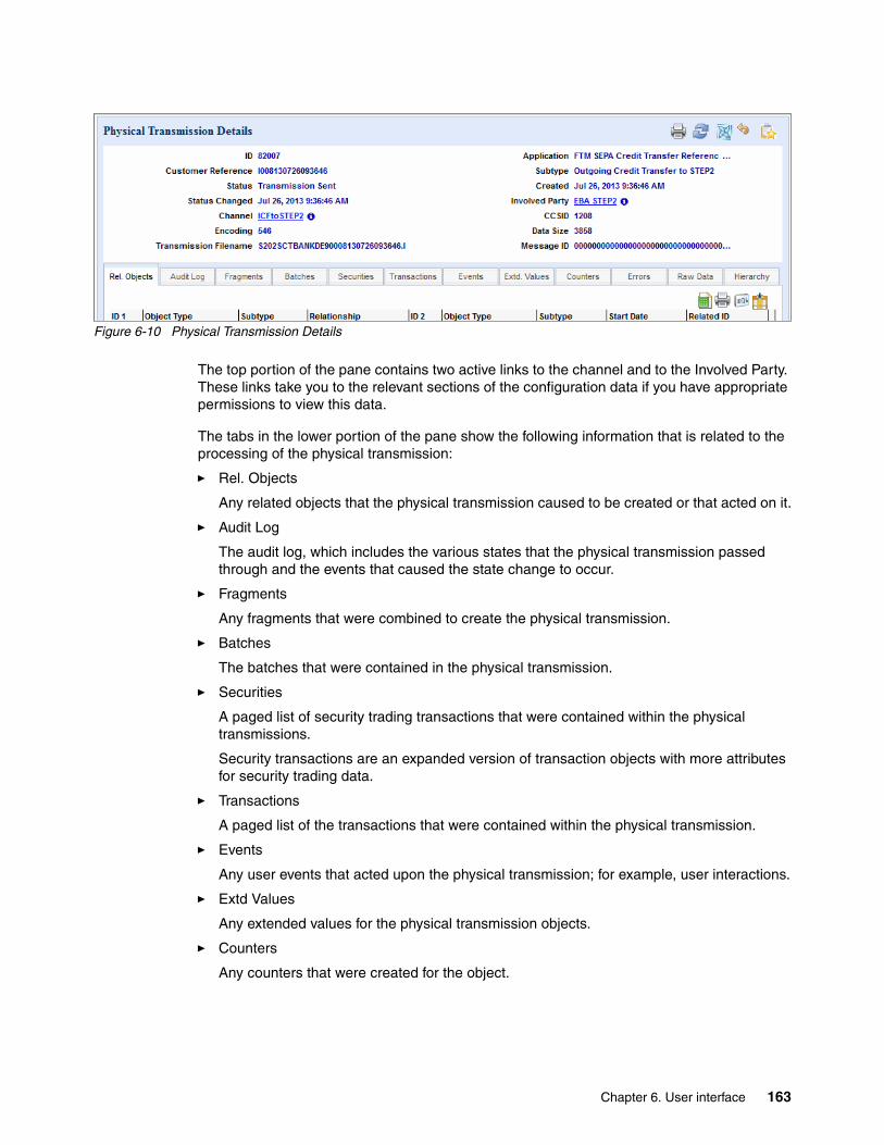
Figure 6-10 Physical Transmission Details
The top portion of the pane contains two active links to the channel and to the Involved Party. These links take you to the relevant sections of the configuration data if you have appropriate permissions to view this data.
The tabs in the lower portion of the pane show the following information that is related to the processing of the physical transmission:
� Rel. Objects
Any related objects that the physical transmission caused to be created or that acted on it.
� Audit Log
The audit log, which includes the various states that the physical transmission passed through and the events that caused the state change to occur.
� Fragments
Any fragments that were combined to create the physical transmission.
� Batches
The batches that were contained in the physical transmission.
� Securities
A paged list of security trading transactions that were contained within the physical transmissions.
Security transactions are an expanded version of transaction objects with more attributes for security trading data.
� Transactions
A paged list of the transactions that were contained within the physical transmission.
� Events
Any user events that acted upon the physical transmission; for example, user interactions.
� Extd Values
Any extended values for the physical transmission objects.
� Counters
Any counters that were created for the object.
Chapter 6. User interface 163

� Error
Any errors that the physical transmission encountered.
Errors include syntactical errors (such as mapping errors) or semantic errors (such as currency not valid for payment type).
� Raw Data
The raw data or payload in the external format as received or transmitted.
� Hierarchy
The relations between the physical transmissions and its related objects; for example, the transmission that it contains and any object it creates.
Audit Log tabFinancial Transaction Manager can log each state change that an object goes through and the event that caused it to reach that state. It includes a time stamp to show when the state change occurred. You can use the audit log to examine the physical transmissions process flow to ensure that the physical transmission was processed correctly, which shows where the process waited for a response from a third-party application or user.
Figure 6-11 shows the contents of the Audit Log tab.
Figure 6-11 Physical Transmission Details, Audit Log tab
164 Financial Transaction Manager Technical Overview
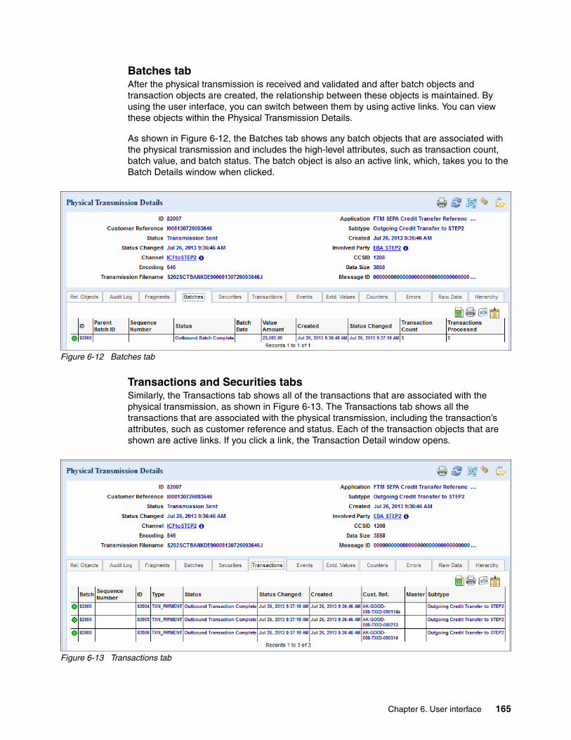
Batches tabAfter the physical transmission is received and validated and after batch objects and transaction objects are created, the relationship between these objects is maintained. By using the user interface, you can switch between them by using active links. You can view these objects within the Physical Transmission Details.
As shown in Figure 6-12, the Batches tab shows any batch objects that are associated with the physical transmission and includes the high-level attributes, such as transaction count, batch value, and batch status. The batch object is also an active link, which, takes you to the Batch Details window when clicked.
Figure 6-12 Batches tab
Transactions and Securities tabsSimilarly, the Transactions tab shows all of the transactions that are associated with the physical transmission, as shown in Figure 6-13. The Transactions tab shows all the transactions that are associated with the physical transmission, including the transaction’s attributes, such as customer reference and status. Each of the transaction objects that are shown are active links. If you click a link, the Transaction Detail window opens.
Figure 6-13 Transactions tab
Chapter 6. User interface 165

The Securities tab shows details that are similar to the Transactions tab, but other attributes for securities trading also are included; for example, Instrument and Fund Manager. You can use the Transactions tab on the Physical Transmission Details window to examine the details of all of the transactions that are received within a customer file; for example, checking their status or attributes, such as value date, currency, and amount.
Raw Data tabBy using the Physical Transmission Details, you can view the transaction data as it was received in the original format. You can use this information to confirm that the transaction data is being processed correctly and that it conforms to the data that was received. This information is shown on the Raw Data tab, as shown in Figure 6-14.
Figure 6-14 Raw Data tab
6.3.2 Fragments
Fragments within Financial Transaction Manager represent a piece or fragment of a larger physical transmission that is split to facilitate processing; for example, salary files and pension payment files. By using the Fragment function, you can search and monitor the reception and creation of fragments.
166 Financial Transaction Manager Technical Overview

Fragment Search criteriaFigure 6-15 shows the Fragment Search pane.
Figure 6-15 Fragment Search criteria pane
This pane includes the following search fields:
� ID
The identification that Financial Transaction Manager assigned to the fragment.
� Customer Reference
The customer reference for the fragment.
� UID
Another identification set as required when the fragment is received; for example, a third-party application’s reference.
� Subtype
The subtype of the fragment.
� Status
The status of the fragment; for example, Inbound Transmission Complete and Transmission sent.
� Created
The creation date and time of the fragment transmission, which can be set to search in a time period or between two dates. The key word TODAY can be used.
Chapter 6. User interface 167

� Status Changed
The date and time when the fragment’s state changed.
Fragment Search ResultsWhen a query is run, the Fragments Results show the fragments that satisfy that query. By using the Fragments Results (see Figure 6-16), you can identify the health of a fragment. A green dot denotes complete, an amber dot denotes warning, and a red exclamation denotes an error.
Figure 6-16 Fragments Search Results
You can configure the columns that display by using the Pick Columns option to add or remove columns as required. You can also select the fragment that you want to examine to access the Fragment Details.
Fragment DetailsYou can use the Fragments Details (see Figure 6-17) primarily to examine the fragment and the states through which it passed and to examine the data that was received or transmitted. The top portion of the pane shows expanded information about the attributes of the fragment. The lower portion of the pane shows information that is related to details about the process flow that it followed.
The top portion of the pane also contains an active link to the physical transmission that includes the fragment.
Figure 6-17 Fragment Details
168 Financial Transaction Manager Technical Overview

The following tabs in the lower portion of the pane show information that is related to the processing of the physical transmission:
� Rel. Objects
Shows any related objects that the fragment caused to be created or that acted on it. For physical transmissions, this tab often contains no data.
� Audit Log
Shows the audit log in the various states that the physical transmission passed through, and the events that caused the state change to occur. You can configure the process flow such that not all states are logged in the audit log.
� Physical Transmission
Shows details of the physical transmission with which the fragment is associated.
� Batches
Shows the batches that were contained in the fragment.
� Events
Shows any user events that acted upon the fragment; for example, user interactions.
� Extd Values
Lists any extended values that are saved with the fragment; for example, variables that are to be used in mapping or downstream processing.
� Counters
Lists any counters that created for the object.
� Error
Lists any errors that the fragment encountered.
� Raw Data
Shows the incoming or outgoing data in the format that it put to or was received from the file, queue, and so on.
� Hierarchy
Shows the relations between the fragment and its related objects; for example, the physical transmission that contains it and any object it creates
Audit Log tabThe Audit Log tab shows each of the states that the fragment passed through during its lifecycle, as shown in Figure 6-18 on page 170.
Chapter 6. User interface 169

Figure 6-18 Audit Log tab
Physical Transmission tabBy using the Physical Transmission tab, you can access details about the physical transmission of which this fragment is part, as shown in Figure 6-19. The tab also provides details, such as the involved party and the channel on which the data arrived, which allows for quick access to details.
Figure 6-19 Physical Transmission tab
170 Financial Transaction Manager Technical Overview

Raw Data tabYou can view the fragment’s raw data that is received on the channel by using the Raw Data tab, as shown in Figure 6-20.
Figure 6-20 Raw Data tab
6.3.3 Batches
By using the Batches function, you can search for any batches that are received or transmitted. The primary use of this function is to search for batches and to view their attributes; for example, comparing the number of transactions that are contained within the batch against the number processed.
Batch Search criteriaFigure 6-21 on page 172 shows the Batch Search criteria pane.
Chapter 6. User interface 171

Figure 6-21 Search Definition pane for batches
This pane includes the following search fields:
� ID
The identification that Financial Transaction Manager assigned to the batch.
� Parent Batch ID
The identification of the batch that contained the batch.
� Batch Reference
The reference identification of the batch; for example, contained within the batch header.
� UID
Another identification that can be set as required when the batch is created with Financial Transaction Manager; for example, a third-party application’s batch reference.
� Subtype
The subtype of the batch; for example, payroll and corporate payment instruction.
172 Financial Transaction Manager Technical Overview

� Status
The status of the batch; for example, Waiting for Transactions to Complete and Batch Validating.
� Batch Date
The date the batch was created by a client or application, which is often contained within the batch header.
� Created
The creation date and time of the batch object within Financial Transaction Manager, which can be set to search in a specific period or between two dates and can use the key word TODAY.
� Status Changed
The date and time when the physical transmission’s state changed.
Batch Search ResultsWhen a query is run, the Batch Search Results show the batches that satisfy that query, as shown in Figure 6-22. By using these results, you can view the status of the batch and view the primary attributes of the batch. You can configure this view to add or remove columns by using the Pick Column icon.
Figure 6-22 Batch Search Results
The results that are shown are active links. Clicking a link takes you into the Batch Details.
Chapter 6. User interface 173

Batch DetailsYou can access the Batch Details from the Batch Results or from the Batches tab of the Physical Transmission or Transaction Details. The Batch Details displays more detailed information about an individual batch. The top portion of the pane shows expanded information about the attributes of the batch, and the lower portion of the pane shows information that is related to details about the process flow that it followed. Figure 6-23 shows an example of the Batch Details.
Figure 6-23 Batch Details
The top portion of the pane shows expanded information about the major attributes of the batch; for example, batch reference, batch state, transaction count, and batch value. You can ascertain where the batch is within its lifecycle and if the transactions it contains are processed. It also contains an active link to the Physical Transmission, with which you can access details about how the batch was received or created; for example, file name and queue name.
The tabs in the lower portion of the pane show the following information that is related to batch processing:
� Rel. Objects
Shows any related objects that the batch caused to be created or that acted on it.
� Audit Log
Shows the audit log with the various states that the batch passed through and the events that caused the state change to occur.
� Physical Transmission
Shows the physical transmission in which the batch was received or transmitted.
� Batches
Shows any batches that were contained within the batch; for example, nested batches.
� Securities
Shows any security trading transactions that were contained within the batch.
Security transactions are an expanded version of transaction objects with other attributes for security trading data.
� Transactions
Shows the transactions that were contained within the batch.
174 Financial Transaction Manager Technical Overview

� Events
Shows any user events that acted upon batch; for example, user interactions.
� Extd Values
Lists any extended values that are saved with the batch objects; for example, variables to be used in downstream processing.
� Counters
Lists any counters that were created for the object.
� Errors
Shows any errors that are associated with the batch.
� Hierarchy
Shows the relations between the batch and its related objects; for example, the physical transmission that it was part of or the transactions it contains.
The primary tabs that are used in this pane are the Audit Log tab, which shows the state changes and any actions on the object; the Physical Transmission tab, which provides information about how the batch was received, and the Transactions tab, which shows the transactions that are contained within the batch.
Audit Log tabFigure 6-24 shows the Batch Details Audit Log tab. This tab shows the states that the batch passed through during its lifecycle and the events that caused that state change. A time stamp is also logged with each audit entry. This information is useful for investigating any unexpected issues that arise and identifying slow processes; for example, a response from a third-party system might be slow.
Figure 6-24 Audit Log tab
Chapter 6. User interface 175

Physical Transmission tabAs shown in Figure 6-25, the Physical Transmission tab shows the attributes of the physical transmission in which the batch was received or transmitted. It includes attributes, such as status, file name, the involved party, and the channel that received or emitted the physical transmission. By using the active links within the physical transmission details, you can directly open the details of the involved party and channel.
Figure 6-25 Physical Transmission tab
Transaction tabAs shown in Figure 6-26, the Transactions tab shows all of the transactions that are contained in the batch. By using this tab, you can validate the number of transactions within the batch with transaction count and examine the status of the transactions.
Figure 6-26 Transactions tab
176 Financial Transaction Manager Technical Overview
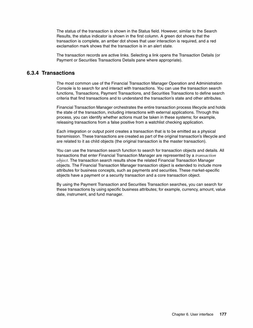
The status of the transaction is shown in the Status field. However, similar to the Search Results, the status indicator is shown in the first column. A green dot shows that the transaction is complete, an amber dot shows that user interaction is required, and a red exclamation mark shows that the transaction is in an alert state.
The transaction records are active links. Selecting a link opens the Transaction Details (or Payment or Securities Transactions Details pane where appropriate).
6.3.4 Transactions
The most common use of the Financial Transaction Manager Operation and Administration Console is to search for and interact with transactions. You can use the transaction search functions, Transactions, Payment Transactions, and Securities Transactions to define search criteria that find transactions and to understand the transaction’s state and other attributes.
Financial Transaction Manager orchestrates the entire transaction process lifecycle and holds the state of the transaction, including interactions with external applications. Through this process, you can identify whether actions must be taken in these systems; for example, releasing transactions from a false positive from a watchlist checking application.
Each integration or output point creates a transaction that is to be emitted as a physical transmission. These transactions are created as part of the original transaction’s lifecycle and are related to it as child objects (the original transaction is the master transaction).
You can use the transaction search function to search for transaction objects and details. All transactions that enter Financial Transaction Manager are represented by a transaction object. The transaction search results show the related Financial Transaction Manager objects. The Financial Transaction Manager transaction object is extended to include more attributes for business concepts, such as payments and securities. These market-specific objects have a payment or a security transaction and a core transaction object.
By using the Payment Transaction and Securities Transaction searches, you can search for these transactions by using specific business attributes; for example, currency, amount, value date, instrument, and fund manager.
Chapter 6. User interface 177

Figure 6-27 shows the three transaction search panes. These search criteria panes return transactions with the Transactions, Payment Transactions, and Securities Transactions results. These results also differ from the columns within the Payments and Securities results and reflect other payments and securities information.
Figure 6-27 Transaction Search panes
Hint: Searching for Master transactions simplifies only the results because child transactions are not displayed in the results.
178 Financial Transaction Manager Technical Overview

Figure 6-28, Figure 6-29, and Figure 6-30 on page 180 shows these panes.
Figure 6-28 Transactions results
The Transactions results show details of all transaction objects and their related objects; for example, the physical transmission and status. All transactions are shown in this search. Figure 6-28 shows the transaction types of Payment Transaction and Transaction because both Payment and Securities Transactions are types of the more general Transaction type.
The payment results shows only transactions of type Payment Transaction, as shown in Figure 6-29. The payment results columns show more payment-specific information, such as accounts, currency, and amount.
Figure 6-29 Payment results
Chapter 6. User interface 179

The Securities Transaction results columns show more securities trading-specific information, such as accounts, quantity, and instrument, as shown in Figure 6-30.
Figure 6-30 Securities results
By selecting a transaction in any of the results, the details that are appropriate for the transaction are displayed. These details are similar and only the expanded data that is shown in the top portion of the pane is different.
Figure 6-31, Figure 6-32 on page 181, and Figure 6-33 on page 182 show the transaction details for transactions, payment transactions, and securities trading transactions.
Figure 6-31 Transaction Details
Transaction Details show the expanded details that are related to the specific Financial Transaction Manager objects; for example, for incoming transmissions, the physical transmission that contained the transaction, the format of the message that was received, and the involved party from which it came. These details are useful to understand how the transaction was received and how the raw data was mapped into the Financial Transaction Manager’s internal standard format.
180 Financial Transaction Manager Technical Overview
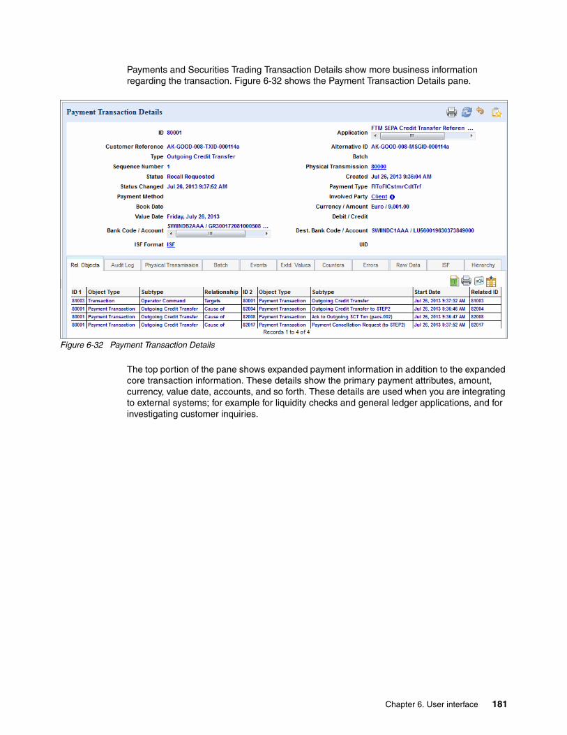
Payments and Securities Trading Transaction Details show more business information regarding the transaction. Figure 6-32 shows the Payment Transaction Details pane.
Figure 6-32 Payment Transaction Details
The top portion of the pane shows expanded payment information in addition to the expanded core transaction information. These details show the primary payment attributes, amount, currency, value date, accounts, and so forth. These details are used when you are integrating to external systems; for example for liquidity checks and general ledger applications, and for investigating customer inquiries.
Chapter 6. User interface 181

Figure 6-33 shows the Securities Transaction Details.
Figure 6-33 Securities Transaction Details
The Securities Transaction Details shows the expanded securities trading information and the core transaction details. This information is useful to examine the status of a securities transaction or to inquire about the details of a trade. The lower portion of the pane shows tabs that give more details about the transaction as it is orchestrated and processed by Financial Transaction Manager.
The tabs provide the following information:
� Rel. Objects
Shows any related objects that the transaction caused to be created or that acted on it.
� Audit Log
Shows the audit log with the various states that the transaction passed through and the events that caused the state change to occur.
� Physical Transmission
Shows the physical transmission that contains the transaction.
� Events
Shows any user events that acted upon the transaction; for example, user interactions.
� Extd. Values
Lists any extended values that are saved with the transaction object; for example, variables to be used in downstream processing.
� Counter
Lists any counters that were created for the transaction.
� Errors
Shows any errors that are associated with the transaction.
182 Financial Transaction Manager Technical Overview

� Raw Data
Shows the raw data as received in the physical transmission and is present if the physical transmission includes only one transaction.
� ISF
Internal Standard Format (ISF) shows the structure of the Financial Transaction Manager internal standard format representation of the transaction.
� Hierarchy
Shows the relationship between the transaction and its related objects; for example, the physical transmission of which it was part or the transactions it contains.
Rel. Objects tabThe Rel. Objects tab (as shown in Figure 6-34) shows all of the related objects that are linked to the transaction and the type of object and the relationship between them. This information is used to examine which related objects were created; for example, messages that were transmitted to external applications or responses from external applications or from example result messages from a fraud detection system.
Figure 6-34 Rel. Objects tab
Note: These tabs are the same for all transaction types. The following examples use the Payment Transaction Details.
Chapter 6. User interface 183

Audit Log tabThe Audit Log tab (as shown in Figure 6-35) shows each state that the transaction passed through during its lifecycle. It also shows the time stamp of the state change and the event that caused the state change. This information is useful in understanding how a payment is processed, the length of time it took for a process to complete interactions with external systems, and its actual status.
Figure 6-35 Audit Log tab
184 Financial Transaction Manager Technical Overview

Physical Transmission tabThe Physical Transmission and Batch tabs (as shown in Figure 6-36) show the related physical transmission and batch objects that are associated with the transmission. By using these tabs, you can examine the batch (if it exists) of which the transaction was part and the physical transmission that contained it. Through this information, you can examine a transaction from reception to completion; for example, by investigating the batch of which the transaction was part and then the customer file in which it was contained or the channel-specific message that was transmitted.
Figure 6-36 Physical Transmission tab
Chapter 6. User interface 185

Event tabThe Events tab (as shown in Figure 6-37) shows any logged events that acted on the transactions. This tab shows the type of event that acted on the transaction, its severity, and the action that raised the event. You can use this tab to examine user actions that were taken on the transaction; for example, examining the time that was taken between the first and second authorizer.
Figure 6-37 Events tab
186 Financial Transaction Manager Technical Overview

Raw Data tabThe Raw Data tab (as shown in Figure 6-38) displays only if the transaction is not part of a batch, meaning it is a single transaction message. The tab also shows the format and structure of the data as it was received, such as in a file and message queue. If the raw data that is associated with the transaction is XML, it is shown in a tree type structure, as shown in Figure 6-38; otherwise, it displays as text.
Figure 6-38 Raw Data tab
This information is useful when you are examining the fields and the data of the raw data and to understand how the data is mapped into the internal standard format. This can be useful when you are investigating why certain data is not being processed appropriately.
Chapter 6. User interface 187

ISF tabThe ISF tab (as shown in Figure 6-39) shows the ISF representation of the transaction. This information is useful when new integration points are developed; for example, mapping definitions or examining a transaction’s lifecycle to ensure that the correct data is present in the ISF.
Figure 6-39 ISF tab
6.3.5 Resolving alerts and operator actions
When a transaction enters an alert state or a transaction requires user intervention (for example, authorization), a user selects the transaction and selects the resolve action. The resolve action can also be used to manually trigger schedules.
The following types of objects require resolving:
� Objects in an alert state because of a failure; for example, mapping or validation failure� Objects that require user intervention
188 Financial Transaction Manager Technical Overview

Alerts can be viewed in the Alert function. By using the search criteria, you can filter the results that are based on object type, date alert that was raised, and so on. Figure 6-40 shows an example of the alert results.
Figure 6-40 Alert results
To open the objects details panel, select any alert. Then, go to the Errors tab, as shown in Figure 6-41.
Figure 6-41 Errors tab
Chapter 6. User interface 189
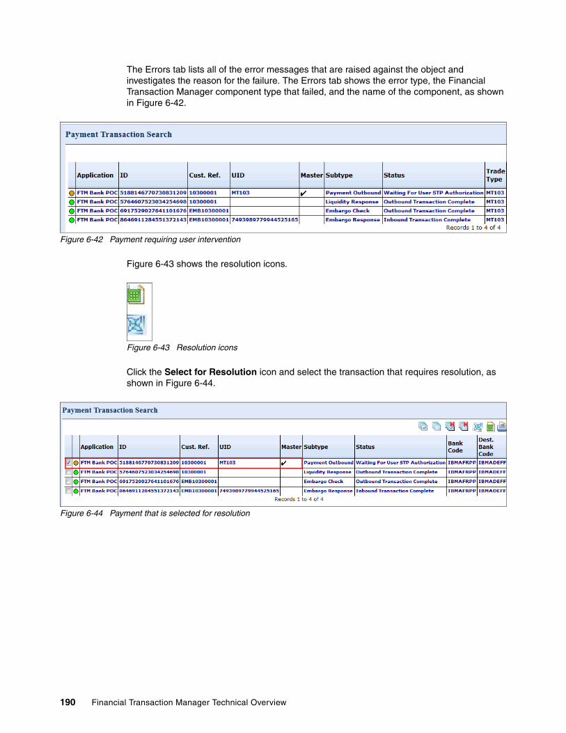
The Errors tab lists all of the error messages that are raised against the object and investigates the reason for the failure. The Errors tab shows the error type, the Financial Transaction Manager component type that failed, and the name of the component, as shown in Figure 6-42.
Figure 6-42 Payment requiring user intervention
Figure 6-43 shows the resolution icons.
Figure 6-43 Resolution icons
Click the Select for Resolution icon and select the transaction that requires resolution, as shown in Figure 6-44.
Figure 6-44 Payment that is selected for resolution
190 Financial Transaction Manager Technical Overview
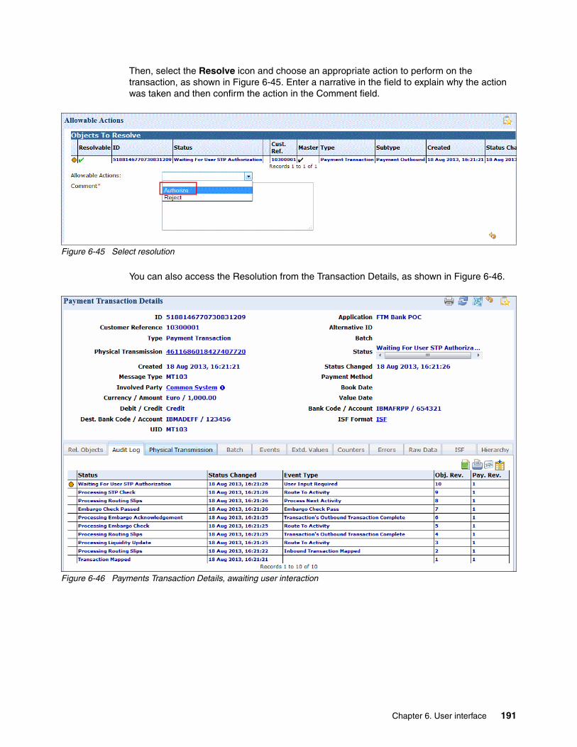
Then, select the Resolve icon and choose an appropriate action to perform on the transaction, as shown in Figure 6-45. Enter a narrative in the field to explain why the action was taken and then confirm the action in the Comment field.
Figure 6-45 Select resolution
You can also access the Resolution from the Transaction Details, as shown in Figure 6-46.
Figure 6-46 Payments Transaction Details, awaiting user interaction
Chapter 6. User interface 191

When you select the Resolve icon, the Allowable Actions that are shown in Figure 6-47 displays. As with your previous actions, you must select an appropriate action to take, insert a comment, and then confirm the action. When the action is confirmed, a command is placed on the Financial Transaction Manager command queue and is processed by the Event Processing flow.
Figure 6-47 Payments Transaction Details, awaiting user interaction
For a user to take an action to resolve a transaction, the action first must be defined in the finite state machine within Rational Software Architect. The actions are defined on the state (for example, Awaiting Authorization) as a constraint, as shown in Figure 6-48. Therefore, it is important to carefully consider user interaction points when the finite state machine is designed.
Figure 6-48 Actions that are allowed on an object in a resolvable state
6.4 Configuring Financial Transaction Manager
The Configuration Data menu group includes functions that with which technical users can view, create, modify, or delete configuration data within Financial Transaction Manager. These functions include definition of interfaces, scheduled processes, and solution variables. This menu group is accessible only to users with administrator privileges in the Financial Transaction Manager Operation and Administration Console.
192 Financial Transaction Manager Technical Overview

Configuration data can be defined within Rational Software Architect as part of the finite state machine mode and is extracted from there and loaded into the database. This method allows for most of the configuration data to maintained and controlled by using standard source control methodologies.
Many of the configuration objects are closely linked to the artifacts that are created within IBM WebSphere Message Broker. For example, mappers within Financial Transaction Manager must have the same name as the label name of the Mapper subflow.
Figure 6-49 shows the Configuration Data menu group.
Figure 6-49 Configuration Data menu group
The Configuration Data menu includes the following items:
� Formats
Defines the structure of the data that is received or transmitted from Financial Transaction Manager.
� Mappers
Defines the mapping component to be used when raw data is transformed to and from the Financial Transaction Manager internal standard format.
� Involved Parties
Defines the application, customer, or network that is involved in an interface.
� Calendar Groups
Defines calendars, working days, and holidays.
� Scheduler Tasks
Defines time triggered processes.
� Channels
Defines the physical location on which data is received or transmitted.
� Services
Defines the service to which service participants are attached.
� Service Participants
Defines the service participant, including the incoming or outgoing channel that is associated with it.
Chapter 6. User interface 193

� Classifications
Defines Financial Transaction Manager variables, including those that control how data is shown within the user interface.
� Configuration Values
Defines variables that can be used in other components and processes.
� Authorizations
Defines group permissions that control user access to data and functions.
This section focuses on the configuration data that is used to define interfaces, calendars, and system variables.
6.4.1 Defining interfaces
Interfaces to external systems and networks can be maintained within the Financial Transaction Manager Operation and Administration console.
An interface consists of the following components:
� The definition of the incoming data format.
� The definition of the mapper that is used to transform the data to and from the Financial Transaction Manager internal standard format.
� The physical data source from which the data is received or to which data is transmitted. In Financial Transaction Manager, these data sources are defined as channels.
� The customers, applications, and networks that are involved in the interface.
Several common icons are used throughout the configuration panes, as shown in Figure 6-50.
Figure 6-50 Common configuration icons
194 Financial Transaction Manager Technical Overview

FormatsBy using the formats function within Financial Transaction Manager, users can specify the format of messages that are received or transmitted on a Channel; for example SWIFT MT103, EDI 820, and setr.010.001.003, as shown in Figure 6-51.
Figure 6-51 Format Details pane
The Format Details show the expanded details of the format and includes the following fields:
� ID
The internal Financial Transaction Manager identifier for the format.
� Description
User-defined description of the format.
� Message Domain
The IBM WebSphere Message Broker domain that the format uses. This field is required only if the format is described by a WebSphere Message Broker message set.
� Message Set
The message set of the format as defined within WebSphere Message Broker sets. This field is required only if the format is described by a WebSphere Message Broker message set.
� Message Type
The message type as defined within WebSphere Message Broker. This field is required only if the format is described by a WebSphere Message Broker message set.
� Message Format
The message format as defined within IBM WebSphere Message Broker. This field is required only if the format is described by a WebSphere Message Broker message set.
� Application
The application with which this format is associated.
� Application Version
The version of the application with which this format is associated.
Chapter 6. User interface 195
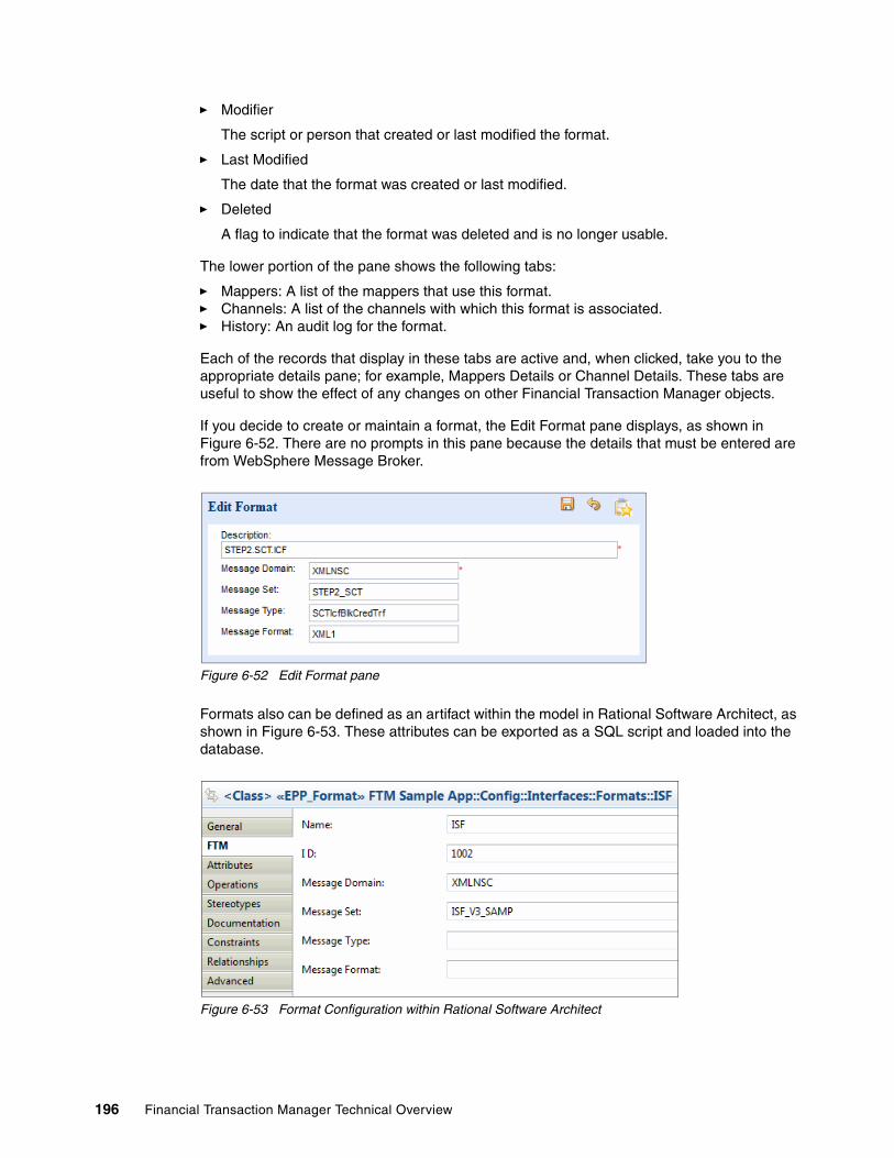
� Modifier
The script or person that created or last modified the format.
� Last Modified
The date that the format was created or last modified.
� Deleted
A flag to indicate that the format was deleted and is no longer usable.
The lower portion of the pane shows the following tabs:
� Mappers: A list of the mappers that use this format.� Channels: A list of the channels with which this format is associated.� History: An audit log for the format.
Each of the records that display in these tabs are active and, when clicked, take you to the appropriate details pane; for example, Mappers Details or Channel Details. These tabs are useful to show the effect of any changes on other Financial Transaction Manager objects.
If you decide to create or maintain a format, the Edit Format pane displays, as shown in Figure 6-52. There are no prompts in this pane because the details that must be entered are from WebSphere Message Broker.
Figure 6-52 Edit Format pane
Formats also can be defined as an artifact within the model in Rational Software Architect, as shown in Figure 6-53. These attributes can be exported as a SQL script and loaded into the database.
Figure 6-53 Format Configuration within Rational Software Architect
196 Financial Transaction Manager Technical Overview

MappersBy using the mappers function in Financial Transaction Manager, you can search for, create, and maintain mapper definitions. The defined mappers are directly linked to the mapper flows that are created within WebSphere Message Broker. When a mapper is selected, the details display, as shown in Figure 6-54.
Figure 6-54 Mapper Details
The Mapper Details pane includes the following information:
� ID
The internal Financial Transaction Manager identifier for the mapper.
� Description
User-defined description of the format.
� Name
The name of the mapper, which must be the same as the Mapper label name in WebSphere Message Broker.
� Format
The format of the message that the mapper transforms to or from ISF.
� Inbound
Flag if the mapper is for inbound or outbound transformation.
� Subtype
The subtype, if any, of the message to be transformed.
� ISF Format
The version of the ISF that the mapper maps to or from.
� Application
The application with which this format is associated.
� Application Version
The version of the application with which this format is associated.
� Modifier
The script or person that created or last modified the format.
Chapter 6. User interface 197
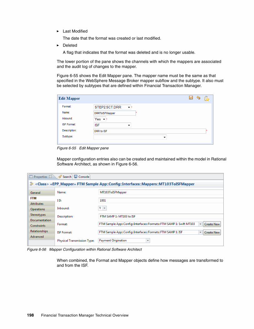
� Last Modified
The date that the format was created or last modified.
� Deleted
A flag that indicates that the format was deleted and is no longer usable.
The lower portion of the pane shows the channels with which the mappers are associated and the audit log of changes to the mapper.
Figure 6-55 shows the Edit Mapper pane. The mapper name must be the same as that specified in the WebSphere Message Broker mapper subflow and the subtype. It also must be selected by subtypes that are defined within Financial Transaction Manager.
Figure 6-55 Edit Mapper pane
Mapper configuration entries also can be created and maintained within the model in Rational Software Architect, as shown in Figure 6-56.
Figure 6-56 Mapper Configuration within Rational Software Architect
When combined, the Format and Mapper objects define how messages are transformed to and from the ISF.
198 Financial Transaction Manager Technical Overview

Involved Parties functionThe Involved Parties function is used to create and maintain objects that represent the systems, networks, and clients that receive data from or transmit data to Financial Transaction Manager. Involved Parties are used to show ownership of messages and channels. You can use this information to create data segregation and, with the Financial Transaction Manager security model, control user access to data. Figure 6-57 shows the Involved Parties Details pane.
Figure 6-57 Involved Parties Details pane
This pane displays the following details:
� ID
The internal Financial Transaction Manager identifier for the involved party.
� Name
The name of the involved party.
� External ID
The external identifier for the party; for example, customer name and application name.
� Description
Description of the involved party.
� Effective Date
The date on which this involved party becomes active.
� End Date
The date on which the involved party becomes invalid.
� Parent
The name of the parent-involved party; for example, a division in a financial institution.
� Application
The application with which this Involved Party is associated.
� Application Version
The version of the application with which this Involved Party is associated.
Chapter 6. User interface 199

� Modifier
The script or person that created or last modified the Involved Party.
� Last Modified
The date that the Involved Party was created or last modified.
� Deleted
A flag that indicates that the Involved Party was deleted and is no longer usable.
The lower portion of this pane shows the calendars that are associated with this Involved Party, which defines working days, holidays, and so forth. For more information, see 9.12, “Scheduled activity pattern” on page 415.
Figure 6-58 shows the Edit Involved Party pane.
Figure 6-58 Edit Involved Party pane
In addition, you can create and maintain Involved Parties within the model in Rational Software Architect, as shown in Figure 6-59.
Figure 6-59 Involved Parties configuration within Rational Software Architect
200 Financial Transaction Manager Technical Overview
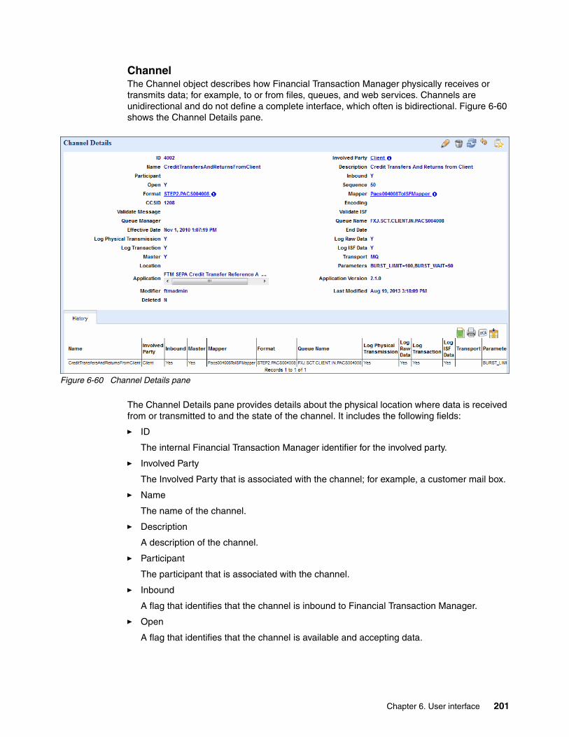
ChannelThe Channel object describes how Financial Transaction Manager physically receives or transmits data; for example, to or from files, queues, and web services. Channels are unidirectional and do not define a complete interface, which often is bidirectional. Figure 6-60 shows the Channel Details pane.
Figure 6-60 Channel Details pane
The Channel Details pane provides details about the physical location where data is received from or transmitted to and the state of the channel. It includes the following fields:
� ID
The internal Financial Transaction Manager identifier for the involved party.
� Involved Party
The Involved Party that is associated with the channel; for example, a customer mail box.
� Name
The name of the channel.
� Description
A description of the channel.
� Participant
The participant that is associated with the channel.
� Inbound
A flag that identifies that the channel is inbound to Financial Transaction Manager.
� Open
A flag that identifies that the channel is available and accepting data.
Chapter 6. User interface 201

� Sequence
The sequence of the channel, which can be used to define various channels that are started based on its sequence; for example, if sequence number 1 fails, the channel with sequence number 2 is started.
� Format
The structure of the data that is received by the channel.
� Mapper
The mapper to be used to transform received data to or transmitted data from the international standard format.
� CCSID
The character code setting ID of the data.
� Encoding
The encoding of the data.
� Validate Message
A flag that identifies whether a message is syntactically validated when it is received.
� Validate ISF
A flag that identifies whether the ISF is validated for structure and content during the mapper transformation.
� Queue Manager
The IBM WebSphere MQ Queue Manager to which Financial Transaction Manager connects to read or write data, if applicable.
� Queue Name
The IBM WebSphere MQ Queue name that Financial Transaction Manager reads from or writes to, if applicable.
� Effective Date
The date from which the channel becomes active.
� End Date
The date on which the channel becomes deactivated.
� Log Physical Transmission
A flag that identifies whether physical transmissions are logged in the Financial Transaction Manager database.
� Log Raw Data
A flag that identifies whether raw data received is logged in the Financial Transaction Manager database.
� Log Transaction
A flag that identifies whether transactions that were created from the raw data are logged in the Financial Transaction Manager database.
� Log ISF data
A flag that identifies whether the internal standard format data is logged in Financial Transaction Manager database.
202 Financial Transaction Manager Technical Overview

� Master
A flag that indicates whether transactions are associated with the Channel are Master transactions.
� Transport
Defines the transport protocol that is used in the Channel; for example file, WebSphere MQ, HTTP, and email.
� Location
The location to which data is read from or written.
� Parameters
Lists any channel-specific parameters; for example, burst mode and transaction subtype.
� Application
The application with which this channel is associated.
� Application Version
The version of the application with which this channel is associated.
� Modifier
The script or person that created or last modified the channel.
� Last Modified
The date that the channel was created or last modified.
� Deleted
� A flag that indicates that the channel was deleted by a user and is no longer active.
The channel attributes include options to turn off the syntactic validation of the ISF and the received messages. You can use these options if a customer or external application sends data that does not match the message definitions that are defined on the channel but if the data should be accepted.
Four logging options also control whether the physical transmission, transaction, raw data, or internal standard format is written to the database. You can use these options when it is not necessary to log all the data; for example, if a copy of the transaction is kept in a third-party system or if there is no business requirement to log the entire transaction. Raw data logging can also be deactivated on a channel for performance reasons; for example, high-volume, low-value payments might not need to be fully logged.
Chapter 6. User interface 203

Channels can be created in advance and activated when required; for example, when a new customer or application is attached to Financial Transaction Manager. Channels also can be maintained within Rational Software Architect, as shown in Figure 6-61.
Figure 6-61 Channel configuration within Rational Software Architect
204 Financial Transaction Manager Technical Overview

Services and Service ParticipantsThe Service object defines the service that Financial Transaction Manager is providing; for example, Payment Processing and Securities Trading Processing. The Service object is associated with a number of Service Participants and represents a bidirectional interface that combines incoming and outgoing channels. Figure 6-62 shows the Service Details pane.
Figure 6-62 Service Details pane
The Service Details pane shows the Service Participants that are associated with the Service. It also shows the history detail for the Service object. If a Service Participant enters an alert state, a red exclamation mark is shown beside it. Figure 6-63 shows the Service Participant Details pane.
Figure 6-63 Service Participant Details pane
Chapter 6. User interface 205

The Service Participant Details pane provides the following information.
� ID
The internal Financial Transaction Manager identifier for the Service Participant.
� Application
The application that is associated with the Service Participant.
� Service Participant Name
The name of the Service Participant.
� Service Name
The name of the Service that is associated with the Service Participant.
� Status
The status of the Service Participant; for example, Available.
� Inbound Channel
The Channel on which transactions are received into Financial Transaction Manager from the Service Participant.
� Outbound Channel
The Channel on which messages are transmitted to the Service Participant from Financial Transaction Manager.
� Role
The role of the Service Participant within the Service.
� Rank
The rank of the Service Participant, for example primary or secondary.
� Processing Date
The processing date of the Service Participant.
� Open Time
The time at which the Service Participant becomes active.
� Close Time
The time at which the Service Participant deactivates.
� Correlation Scheme
The name of the scheme used for correlation.
� End Mapper Correlation
The name of the End Mapper used for correlation.
� Application Version
The version of the application with which this channel is associated.
� Modifier
The script or person that created or last modified the channel.
� Last Modified
The date that the channel was created or last modified.
� Deleted
A Flag that indicates that the channel was deleted by a user and is no longer active.
206 Financial Transaction Manager Technical Overview

You can create and maintain Services and Service Participants within Rational Software Architect, as shown in Figure 6-64 and Figure 6-65.
Figure 6-64 Service configuration within Rational Software Architect
Figure 6-65 Service Participation configuration within Rational Software Architect
Chapter 6. User interface 207

6.4.2 Calendars and Schedules
Many transactions can be processed only on working days or during specific time windows; for example, currency cut-off times for payments. With Financial Transaction Manager, you can create calendars and schedules that can hold details of working days, holidays, and processing windows in the Calendar Group Details pane, as shown in Figure 6-66.
Figure 6-66 Calendar Group Details, Calendar tab
The Calendar Group Details Calendar tab shows the holidays that are entered as part of the calendar group. These holidays can be used to validate payments or to release payments if Financial Transaction Manager is configured with a payment warehouse.
The Schedule tab (as shown in Figure 6-67) shows the time when the various calendars are active and which days are working days. Calendars can be linked to Involved Parties and can define when those Involved Parties are active.
Figure 6-67 Schedule tab
208 Financial Transaction Manager Technical Overview

6.4.3 Configuring classifications
You can use classifications within Financial Transaction Manager to control how data is displayed within the Operation and Administration Console and when processing transactions; for example, validation. The Classifications list (as shown in Figure 6-68) shows variables definitions, the classification to which they belong, and their value.
The Code column reflects the value of the field as it is held in the Financial Transaction Manager database. The Description column shows how that value is shown in the Operation and Administration Console. For example, rather than displaying TXN_PAYMENT, the user interface displays Payment Transaction.
Figure 6-68 Classifications
Classifications also support multiple locales, which facilitates native language support.
You can add new classification variables by using the Edit Classification Item pane, as shown in Figure 6-69.
Figure 6-69 Edit Classification Item pane
Chapter 6. User interface 209

6.4.4 Configuring Configuration Values
The Configuration Value function holds variables that are used during processing; for example, setting the environment variable to production. These variables are loaded into memory when WebSphere Message Broker begins.
Figure 6-70 shows the Configuration Values list.
Figure 6-70 Configuration Values list
The configuration values are assigned to various categories and accessed by the key. The list returns the value that is held in the configuration value. You can also group these values and search on the values by category.
6.4.5 User access permissions
The Financial Transaction Manager security model controls user access and permissions by using role-based access. Financial Transaction Manager is delivered with the following default core roles:
� FTMAdmin: Administrator role for Financial Transaction Manager� FTMCfg: Configuration role for Financial Transaction Manager� FTMEdit: Editor role for Financial Transaction Manager� FTMUser: User Role for Financial Transaction Manager
210 Financial Transaction Manager Technical Overview

The permissions that are assigned to these roles can be viewed within the Authorizations list, as shown in Figure 6-71. You can modify the name and nature of these roles as required to fit your individual solution requirements.
Figure 6-71 Authorizations list
You can link groups to Involved Parties and give fine-grained control of user access to operational data. You cannot change the authorization details from within the Operation and Administration console.
Chapter 6. User interface 211

212 Financial Transaction Manager Technical Overview

Chapter 7. Housekeeping
Many standard database maintenance tasks should be carried out regularly, such as runstat and reorg for DB2. However, these tasks are beyond the scope of this chapter.
The maintenance schedule for Financial Transaction Manager is dependent on many factors, not all within the control of Financial Transaction Manager. These factors include complexity, volume, and environment. Database administrators can monitor and adjust the schedule as appropriate. These considerations are not unique to Financial Transaction Manager and are common for all applications that persist data to a database.
In this chapter, we describe the housekeeping and maintenance considerations that are important to ensure the sustainability of the Financial Transaction Manager solution.
This chapter includes the following topics:
� Database archive and purge� Back up and restore� Technical monitoring� Maintenance
7
© Copyright IBM Corp. 2014. All rights reserved. 213

7.1 Database archive and purge
Financial Transaction Manager receives incoming and outgoing transactions from applications, customer channels, networks, and so on. These transactions are persisted within the Financial Transaction Manager database and can be stored with various other pieces of data that can be used for querying, reporting, and so on. This data can include a full audit trail, any messages that are created by the transaction, and a copy of the transaction in its original format and in Financial Transaction Manager’s internal standard format. This flexibility affects the frequency of database maintenance; for example, the greater the volume of data, the more often the database must be maintained.
Therefore, you can purge transactions from the production database to keep its size at the optimal level for the solution’s performance requirements. However, as transactions are purged from the production database, do not merely delete them, but archive the salient data from the transaction as well.
In the following sections, we describe the considerations when you are setting up an archive and purging solution. For more information, see the Financial Transaction Manager 2.1 Information Center.
7.1.1 Identifying transactions
The first step in an archive or purge process is to identify the transactions to remove from the production database. When you are identifying transactions to be archived, consider all of the associated related objects of the transaction. These objects include physical transmissions, batches, and child transactions.
Physical transmissions and batches can contain multiple transactions, and it might not be possible to archive and purge these objects until all of the transactions that they contain are completed and ready to archive. Similarly, do not archive and purge physical transmissions until after all the contained batches and fragments are completed.
In addition, the Financial Transaction Manager data model contains a number of dependencies that must be considered. For more information, see the Financial Transaction Manager Information Center.
When you are identifying transactions that are candidates for archiving and purging, remember the following considerations:
� Has the transaction completed processing?
The transaction’s state identifies whether the processing of the message was completed. This should take into account receipt of acknowledgements. It is also important to consider the transactions that are created by a master transaction. A master transaction is not considered complete until all its child transactions are complete.
� Can the transaction be canceled or rejected?
In many payment schemes (for example SEPA), transactions can be returned or canceled within a certain time period. A completed message should not be purged or archived until after this period passes.
� Regulatory and reporting
Local reporting rules might require that data is kept in the production database until the regulatory reports are submitted. Alternatively, it might be that reports that are created from an archive database are permissible.
214 Financial Transaction Manager Technical Overview

� Business requirements
The length of time that a payment is kept in the production database might be defined by business requirements; for example, for customer queries. Alternatively, an online archive instance of Financial Transaction Manager might be permissible.
� Type of transaction
The type of transaction can have a direct effect on the archive and purge process. For example, low-value, high-volume payments can be archived and purged more often than high-value, low-volume payments.
After the transactions and associated objects are identified, the archive and purge process can be done.
7.1.2 Archive
The archival of Financial Transaction Manager transactions can be performed by using the following processes, depending on the archive requirements:
� Database backup
This type of archiving is the simplest of the archive processes and consists of taking a backup of the Financial Transaction Manager database regularly before purging is done. However, this method of archiving does not allow for easy access to the archived data and requires that the data is restored to be viewed.
� Financial Transaction Manager archive database
This method consists of creating a separate Financial Transaction Manager database and moving the archived transactions to that database. The archive database has the same data model as the production database so no transformation is required. In addition, a separate Operation and Administration Console can be configured to allow users to query on transactions in the archive database. However, a separate purge process specifically for the archive database is required to ensure that the archive database does not grow excessively large.
� Non-Financial Transaction Manager archive database
This method consists of archiving the Financial Transaction Manager transactions to a separate database with a different data model. This method requires some transformation of the data. This method can be used when an existing archive process is in place and the Financial Transaction Manager data should be moved to an existing archive database.
It might be that you use a combination of these methods; for example, a Financial Transaction Manager archive database for operators to query and another archive database for regulatory reporting.
If data is to be archived to an archive database (with or without the same data model), consideration should be given to the information that should be recorded. Transactions within Financial Transaction Manager can be stored with much detail; for example, each state change, full audit, user actions, and raw data format. This volume of data might not be required for archive purposes and a subset of the data can be used. For example, a payment’s lifecycle can be monitored in Financial Transaction Manager and a payment processing engine; therefore, it might not be necessary to store history within the Financial Transaction Manager archive database. However, local regulations might dictate the minimum information that is stored within the archive database and the duration that the information is kept.
Chapter 7. Housekeeping 215

You can implement these archive processes by using the following methods:
� Scheduled database backups
The simplest archive process is to schedule regular backups of the Financial Transaction Manager database. These backups can then be stored; for example, on optical disk.
� Database stored procedures
Stored procedures can be used to identify data and then archive it to the archive database. These stored procedures might be triggered manually or automatically; for example, by the use of a Scheduler Task
� Programmatically
A program might be written to identify and archive transactions.
It is likely that there are various archive requirements for different transaction types, different departments, and so forth. Take care to ensure that this fact is not overlooked.
7.1.3 Purge
The purge process is complementary to the archive process and usually follows directly after the archive process. In a production environment, it is unlikely that a purge occurs without the archive process completed. The purge process removes transactions and associated objects from the production database and frees up database space to ensure that the performance of the solution is kept optimal.
In addition, the purge process ideally deals with the same record set as that of the archive process, which ensures that only those records that are archived are removed. Therefore, it is important to indicate that the archive completed successfully; for example, by the archive process triggering the purge process after completion.
The major consideration when a purge process is created is to ensure that the process takes into account the relationship between database objects; for example, foreign keys on database tables, and, therefore, data might need to be purged in a certain order.
The purge process removes data from the database so care must be taken to ensure that this is done at such a time during the day to ensure that the data is not locked by users or other processes.
For more information, see the Financial Transaction Manager Information Center by clicking Planning Archive and Purge Guidelines.
7.2 Back up and restore
The backup of the database and restoration when required can be part of an archive process. However, this section includes a more general description of a backup/restore strategy. The backup of the Financial Transaction Manager database might be required for the following reasons:
� Financial Institution data policy� Business requirements� Local regulations� Disaster recovery requirements
216 Financial Transaction Manager Technical Overview

Database backups can be triggered to run automatically or manually started. When a backup is to begin, it is important that there are no users or processes interacting with the data to ensure that no database locks occur. The backups can then be stored on a network drive or to media.
The backup contains a snap shot of the Financial Transaction Manager solution at a certain time and is useful for restoring configuration that might be lost or changed. This can be used for investigation and resolution of issues.
A database backup might be required for the following reasons:
� Restoration of lost configuration is needed.
� Recovery to the start of a process; for example, restoring to a situation before an external batch process runs.
� As part of an archive process, restoration of a database for inquiry or reporting purposes.
� For testing purposes, restoration of live or pseudo-live data to a test or development environment.
The restoration of the Financial Transaction Manager database needs a similar amount of care as the backup process. The restore should be performed on a database that is not locked by any user or process to ensure that no database corruption can occur.
In addition, if you are restoring a database from one environment to another (for example, the production database to a test environment), care should be taken to ensure that any production configuration data is corrected before the solution runtime components are restarted.
Restoration of a database can be complete or partial, with the entire database or only certain tables being backed up. In the case of a partial restoration, be careful to ensure that the restoration of the data also takes any foreign key constraints into account.
7.3 Technical monitoring
Financial Transaction Manager can publish events that can inform the business user of the health of the solution. This information includes key performance indicators, such as the number of transactions that are processed successfully. The business user can monitor this information within IBM Business Monitor, which is part of the Financial Transaction Manager solution. However, monitoring the technical health of the system is also a common requirement. Several solutions are available to perform this task and to inform a technical user when there are problems, for example when disk space is decreasing. An example of this type of solution is the IBM Tivoli® suite.
These solutions can be used to monitor the following technical resources:
� Free space within the file system� Number of files within a folder� Volume of messages on queues� Memory usage
Monitoring this information can quickly show if there are issues in the solution. For example, files accumulating in a folder can indicate that a process is not running. This issue potentially allows the technical team to proactively investigate issues before they become critical.
Chapter 7. Housekeeping 217
7.4 Maintenance
The Financial Transaction Manager solution might require updates, including service packs for the database or WebSphere Applications Server and upgrades to message definitions, such as the annual SWIFT standard changes.
Maintenance requires that all or part of the Financial Transaction Manager is unavailable for a short period as the patch or change is applied. The effect of this can be mitigated by deploying flows with different characteristics; for example, geographical location and Financial Transaction Manager applications in their own execution groups within IBM WebSphere Message Broker. In addition, Financial Transaction Manager has the concept of applications, which allow for distinct functionality to be segregated within the Financial Transaction Manager database. This function allows for one application to be upgraded while other applications are unaffected.
Interface Objects within Financial Transaction Manager (for example, channels and scheduler tasks), also can be set to an inactive state, which ensures that they do not attempt to process transactions or transmissions during the scheduled maintenance.
The deployment topology of Financial Transaction Manager also can facilitate maintenance. If the solution was deployed with WebSphere Message Broker LPARS in an active-active or active-passive configuration, one LPAR can be maintained while the other continues processing. When the maintenance is complete, the inactive LPAR can be made active while the second LPAR is upgraded. Schedule maintenance for times when transaction processing is not critical or when few transactions are expected.
The following artifacts or systems might require maintenance or upgrades within the Financial Transaction Manager:
� IBM WebSphere Message Broker message flows and subflows.� IBM WebSphere Message Broker mappers� IBM WebSphere Message Broker message sets� IBM WebSphere Application Server� IBM WebSphere Transformation Extender (if used)� IBM Business Monitor (if used)� IBM DB2� IBM WebSphere MQ� Financial Transaction Manager Operation and Administration Console� IBM Financial Transaction Manager finite state machine model� IBM Financial Transaction Manager configuration model
218 Financial Transaction Manager Technical Overview

Chapter 8. Deployment topologies
This chapter provides information about different deployment topology options that are available in different Financial Transaction Manager components. It includes deployment topologies for the following solutions:
� WebSphere Message Broker� WebSphere MQ� Databases (IBM DB2 and Oracle)� WebSphere Application Server
In this chapter, we also describe deployment topologies for the following Financial Transaction Manager components:
� WebSphere Message Broker flows� DB2 database� Operations and Administration Console (OAC)
The options that are provided in this chapter do not provide an exhaustive list of deployment topology options that are available with Financial Transaction Manager. Contact an infrastructure specialist to choose the correct deployment topology for your requirements.
This chapter includes the following topics:
� Infrastructure topologies� Financial Transaction Manager components
8
Terminology note: The term server is used in this chapter to represent a logical or physical server on multiplatforms or an LPAR on z/OS.
© Copyright IBM Corp. 2014. All rights reserved. 219

8.1 Infrastructure topologies
In this section, we describe different topologies that can be deployed for various Financial Transaction Manager components. The list of topologies that are described here is not exhaustive. Consult an infrastructure specialist to choose the best topology for your solution.
Financial Transaction Manager consists of the following key infrastructure components:
� WebSphere Message Broker � WebSphere MQ� DB2 or Oracle database� WebSphere Application Server
We describe topologies that can be deployed in Financial Transaction Manager.
8.1.1 WebSphere Message Broker and WebSphere MQ
WebSphere Message Broker and WebSphere MQ work together in Financial Transaction Manager. However, these two components are independent components. Because they work together in Financial Transaction Manager, we describe their topologies in this section.
Various deployment topologies that are described in High Availability in WebSphere Messaging Solutions, SG24-7839. In this section, we describe the following key topologies:
� Active-active topology� Active-passive topology
Active-active topologyIn this topology, a network load balancer is used to spread the traffic across two or more brokers that are deployed on the same or different servers. These brokers are deployed in an active-active topology. On each broker, you can develop the flows to multiple execution groups to safeguard against execution group failure. Overall, multiple copies of the flow are listening for inbound message.
In the case of inbound HTTP(S) traffic, different HTTP ports for each execution group allow the load balancer to spread the traffic across all the available instances of the message flows.
In the case of inbound files over FTP or the use of other managed file transfer products, such as IBM Sterling Connect:Direct®, an NFS4 shared drive can be used as inbound directory. The file nodes in WebSphere Message Broker can be configured to point to this inbound directory. By using this topology, any available instance of the flow can pick up the file from the shared location for processing. WebSphere Message Broker ensures that the file is picked by only one instance of the flow.
In case of inbound WebSphere MQ traffic, you can use the following options, depending on the platform that is chosen for deployment:
� Multiplatform
You can use WebSphere MQ clustered queues where the queue managers of each broker are added to a cluster and the input queues of the message flows are defined in the cluster. This method allows the WebSphere MQ cluster to load balance the request to one of the available queue managers.
220 Financial Transaction Manager Technical Overview

� z/OS
On z/OS, you can use the coupling facility (CF) technology to group queue managers of each broker into queue sharing groups (QSGs). All queue managers in a QSG can access shared message queues for sending and receiving messages. Unlike multiplatform, the message can be picked by any message flow that is deployed on any broker.
For more information about this topology, see High Availability in WebSphere Messaging Solutions, SG24-7839.
Effect on availabilityAvailability in this context is a measure of the accessibility of a system or application, not including scheduled downtime. It can be measured as a ratio of expected system up-time relative to the total system time, which includes uptime and recovery time when the system is down, as shown in the following formula:
A = [MTBF/(MTBF + MTTR)] x 100%
The following definitions apply to terms in this equation:
� Mean Time Between Failure (MTBF) is the average elapsed time between failures.
� Mean Time To Recover (MTTR) is the average time that is required to recover from a failure.
This topology provides a high availability configuration to the solution in which there are redundancies within the same broker that uses multiple execution groups and further by using multiple brokers on different servers.
If one broker fails, the system has only half the processing resource available. This event must be factored in when the system is designed. In such cases, the system must be provisioned with appropriate redundancies for high availability, or it must be deemed diminished performance during the recovery time is acceptable.
In the case of WebSphere MQ clustering on multiplatform, a broker failure on a particular server can lead to message pile-up if the queue manager that is associated with that broker is not taken out of the cluster. For example, if the event processing wrapper flow has an WebSphere MQ input node, failure of the broker can cause messages to pile up on the input queue because the cluster queue manager is unaware of stopped broker. This event can cause delay or failure in transaction processing and violate availability requirements.
This scenario can be avoided in z/OS where there is a provision to share the inbound queues across broker instances. Failure of one broker in such case causes other brokers to pick up the messages for processing.
One of the key benefits of the active-active topology is that there is always one instance running to ensure high availability. However, the topology does not safeguard against failure of all the active broker instances. In such a scenario, manual recovery processes must be applied to get the system online.
Chapter 8. Deployment topologies 221

Effect on scalabilityScalability refers to the ability of the application to scale to increased or decreased load. The active-active topology is easily scalable by adding more servers or brokers to the load balancer, adding queue managers to the cluster on multiplatforms, and adding queue managers to QSGs on z/OS. Such changes can also be performed during operational hours, if required. The scalability can also be achieved by adding more execution groups to existing brokers and deploying more copies of message flows. It makes no difference to the scalability of Financial Transaction Manager message flows to deploy more execution groups on a single broker against deploying multiple brokers on multiple servers.
Effect on operabilityThe operability in the case of the active-active topology can be challenging during deployments. Consider a scenario in which message flows are deployed to a number of execution groups across a number of brokers. Now, a patch must be deployed for this message flow. All of the running instances of the message flow must be at the same patch level. Therefore, if you deploy the changes to a running broker, it creates inconsistencies in the execution group. Deployment in such cases can be challenging and might need an outage, which might violate availability requirements. In such cases, phased deployments can be performed.
For example, if there are four brokers that are running in the system, the following steps ensure that there are no inconsistencies in deployed message flows and achieve minimal or zero downtime:
1. Remove broker 1 and 2 from the network load balancer configuration and their corresponding queue managers from WebSphere MQ cluster or QSGs. This method ensures that no traffic is routed to these brokers while deployment is in progress.
2. Deploy the changes on these two brokers.
3. Remove broker 3 and 4 from the network load balancer configuration and their corresponding queue managers from WebSphere MQ cluster or QSGs. At the same time, add brokers 1 and 2 back to the load balancer and clusters. The new messages are now routed to updated message flows.
4. Deploy the changes on brokers 3 and 4 and add them back in the cluster and load balancer.
Active-passive topologyThe active-passive topology can be implemented by using multi-instance queue manager and multi-instance broker capabilities. Figure 8-1 on page 223 shows the multi-instance broker configuration.
Note: In step 3, there is a short period where there are inconsistencies or total downtime of the solution. However, if this step is done in parallel, this period can be made negligible.
222 Financial Transaction Manager Technical Overview
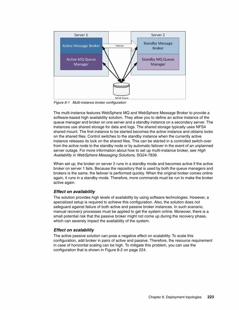
Figure 8-1 Multi-instance broker configuration
The multi-instance features WebSphere MQ and WebSphere Message Broker to provide a software-based high availability solution. They allow you to define an active instance of the queue manager and broker on one server and a standby instance on a secondary server. The instances use shared storage for data and logs. The shared storage typically uses NFS4 shared mount. The first instance to be started becomes the active instance and obtains locks on the shared files. Control switches to the standby instance when the currently active instance releases its lock on the shared files. This can be started in a controlled switch-over from the active node to the standby node or by automatic failover in the event of an unplanned server outage. For more information about how to set up multi-instance broker, see High Availability in WebSphere Messaging Solutions, SG24-7839.
When set up, the broker on server 2 runs in a standby mode and becomes active if the active broker on server 1 fails. Because the repository that is used by both the queue managers and brokers is the same, the failover is performed quickly. When the original broker comes online again, it runs in a standby mode. Therefore, more commands must be run to make the broker active again.
Effect on availabilityThe solution provides high levels of availability by using software technologies. However, a specialized setup is required to achieve this configuration. Also, the solution does not safeguard against failure of both active and passive broker instances. In such scenario, manual recovery processes must be applied to get the system online. Moreover, there is a small potential risk that the passive broker might not come up during the recovery phase, which can severely impact the availability of the system.
Effect on scalabilityThe active passive solution can pose a negative effect on scalability. To scale this configuration, add broker in pairs of active and passive. Therefore, the resource requirement in case of horizontal scaling can be high. To mitigate this problem, you can use the configuration that is shown in Figure 8-2 on page 224.
Chapter 8. Deployment topologies 223

Figure 8-2 Scaling active-passive topology
In this topology, server 1 hosts the passive broker instance of server 2 and vice versa. A network load balancer or WebSphere MQ cluster topologies that are described in “Active-active topology” on page 220 can be used to distribute the traffic across two servers. This provides maximum usage of the server from a scalability perspective, which maintains the high availability aspects. Either of servers serve double the load if there is a broker instance failure. Therefore, the capacity of each server must be adequate to cater to the load.
Effect on operabilityThe deployment process in an active-passive topology is relatively simple. Because the standby broker shares the repository of the active broker, no separate deployment is needed on the standby broker. If a configuration as shown in Figure 8-2 is used, it is effectively a combination of active-active and active-passive topologies.
8.1.2 Database
The database is a critical component of the Financial Transaction Manager solution because it stores configuration and operational data. Financial Transaction Manager supports Oracle and IBM DB2 as the configuration and transaction database. Although the topologies that are described here are for DB2 database, you can implement similar topologies for Oracle database. For more information, see the Oracle database product guide, which is available at this website:
http://docs.oracle.com/cd/E23943_01/core.1111/e12037/intro.htm
224 Financial Transaction Manager Technical Overview

Availability and performance of the database has a direct impact on the overall solution. It is important to consider different deployment topologies for the DB2 database. In this chapter, we do not describe various patterns that are available for availability, scalability, and operability of DB2 database. These patterns are described in the DB2 Information Center, which is available by clicking Database administration High availability and Database administration Administration concepts Databases Database partitions Partitioned database environments.
Patterns also are described in DB2 UDB for z/OS: Design Guidelines for High Performance and Availability, SG24-7134, and DB2 9 for z/OS Performance Topics, SG24-7473.
In this section, we describe the infrastructure decisions that are related to DB2 that affect Financial Transaction Manager operations.
Single database instanceWith this topology, a single instance of the database and database manager is created that manages the Financial Transaction Manager database for configuration and operation data. This database is accessed by all of the WebSphere Message Broker instances that are configured for Financial Transaction Manager, as shown in Figure 8-3.
Figure 8-3 Single database instance
This topology does not provide isolation of data across multiple applications. Although Financial Transaction Manager supports role-based access where individual user groups can be configured to access specific application records, this feature is applicable to the Financial Transaction Manager Operations and Administration user interface only. It does not prevent users with direct database access to view all the records.
Note: The Oracle database is only supported on AIX platform and not on z/OS.
Chapter 8. Deployment topologies 225

Effect on availabilityIn this topology, the database instance is shared across all the Financial Transaction Manager applications that are deployed in one or more brokers. This introduces DB2 database as a single point of failure for all the applications. Therefore, it is important to have high availability strategies in place for single database manager configuration. The Information Center for DB2 Version 9.7 for Linux, UNIX, and Windows section Database administration High availability High availability strategies provides more information about strategies that can be applied for high availability scenarios.
Effect on scalabilityBecause the database is shared across multiple Financial Transaction Manager applications, scalability in this topology can pose problems when the database grows over time. The contention in tables and indexes start to slow down the overall database. Moreover, in case of the multiapplication scenario, if one application has heavy traffic compared to the other, the less frequently used application might starve for resources and might lead to timeouts. However, this situation can be avoided by implementing good housekeeping practices.
You can use the Data Partitioning Feature (DPF) in this case to implement a highly scalable system. A partitioned database is a database that is created across multiple database partitions. Each database partition has its own processes, memory, and data storage. You can create these partitions on multiple servers. Queries that are submitted to the DB2 database are distributed to each database partition and processed in parallel. If there are multiple processors in each database partition node, internal parallelism can be used to achieve better performance.
Effect on operabilityThe topology is easy to manage because there is a single database and database manager to maintain. However, offline backups need all the Financial Transaction Manager applications to be brought down for the period of backup. This downtime can affect availability requirements of a critical application. To prevent access of one application to the users of another, configure Financial Transaction Manager security tables to manage role-based access. This method adds an overhead of managing this configuration on an ongoing basis.
Important: The DB2 Data Partitioning Feature (DPF) requires a separate other license from that of the Enterprise Server Edition (ESE) license that is included with Financial Transaction Manager.
226 Financial Transaction Manager Technical Overview

Multiple database instancesWith this topology, multiple database instances exist for multiple instances of the broker or for multiple applications that are deployed on the same or different brokers, as shown in Figure 8-4.
Figure 8-4 Multiple database instances
Effect on availabilityThe availability of this topology is similar to what is offered by the single instance database because each application or broker has its own database. However, because of multiple instances, the probability of contention in tables and indexes is low. On multiplatforms, the availability of the multiple database instances by using patterns is described in Information Center for DB2 Version 9.7 for Linux, UNIX, and Windows section Database administration High availability High availability strategies. Some of these techniques include clustering and partitioning.
Effect on scalabilityThe solution is scalable by partitioning the Financial Transaction Manager database by using multiple database instances. In such cases, there are two Financial Transaction Manager databases running in parallel on two different servers that are used by applications that are deployed on the same or different brokers. This is applicable to multiplatforms and z/OS implementations. On z/OS specifically, each LPAR can have its own broker and its own database in operation.
Chapter 8. Deployment topologies 227

Effect on operabilityAs the operational data is distributed across multiple databases, operability becomes a challenge. The Financial Transaction Manager Operations and Administration console can connect to only one JDBC data source for its functioning. Therefore, multiple copies of OAC must be deployed to visualize the data. Therefore, a transaction must be searched for in multiple OACs for diagnosis and reporting.
Additionally, it is critical to ensure that the complete lifecycle of a transaction is managed on a server that is connected to same database where the transaction originates. Failing to do so causes failures when Financial Transaction Manager tries to fetch transaction records from the database as a result of an event. This method adds more complexity to the overall solution design.
The decision to have single or multiple database managers can also affect operability of the solution. In some cases, a single database manager can be selected to manage all of the database instances, as shown in Figure 8-5.
Figure 8-5 Multiple database instances with single database manager
However, the topology has an advantage when separate databases are created for separate Financial Transaction Manager applications. In such scenario, this topology provides complete isolation for the application data. Such a capability is useful when there is legal requirement to isolate data for multiple applications.
228 Financial Transaction Manager Technical Overview

Data sharing groupsOn z/OS, the data sharing function can be enabled to allow multiple applications to read from and write to the same DB2 data concurrently. A collection of one or more DB2 subsystems that share DB2 data is called a data sharing group. DB2 subsystems that access shared DB2 data must belong to a data sharing group. All members of a data sharing group share the DB2 catalog and directory, and all members must be in the same IBM Parallel Sysplex®. A Sysplex is a group of z/OS systems that communicate and cooperate with one another by using specialized hardware and software. A Parallel Sysplex is a Sysplex that uses one or more coupling facilities, which provide high-speed caching, list processing, and lock processing for any applications on the Sysplex.
The DB2 for z/OS Information Center section DB2 administration Data sharing Introduction to DB2 data sharing Advantages of DB2 data sharing describes the effect of data sharing groups on availability, scalability, and operability aspects of Financial Transaction Manager database.
For more information about DB2 for z/OS scalability and performance, see DB2 UDB for z/OS: Design Guidelines for High Performance and Availability, SG24-7134, and DB2 9 for z/OS Performance Topics, SG24-7473.
8.1.3 WebSphere Application Server
WebSphere Application Server in Financial Transaction Manager hosts the Financial Transaction Manager OAC application only. It does not participate in transaction processing. Therefore, there are no significant non-functional requirements for this part of Financial Transaction Manager. For more information about various topologies that can be implemented by using WebSphere Application Server, see IBM WebSphere Application Server V8 Concepts, Planning, and Design Guide, SG24-7957.
8.2 Financial Transaction Manager components
In this section, we describe the following components of Financial Transaction Manager:
� Message flows� Database schema configuration� Operations and Administration user interface
8.2.1 Message flows
Financial Transaction Manager includes the following key categories of message flows:
� One or more physical transmission wrapper flows
One physical transmission wrapper flow per external interface in each application in Financial Transaction Manager.
� One or more event processing wrapper flows
One event processing wrapper flow for each Financial Transaction Manager application that encapsulates the actions and mappers for the specific application.
� Heartbeat and error logging flows
A single copy of these message flows for the Financial Transaction Manager applications.
Chapter 8. Deployment topologies 229

These flows can be deployed together and to different execution groups, depending on the requirements. Also, based on performance requirements, you can deploy other instances of the message flows. Various deployment options are available with these flows and how they affect availability, scalability, and operability of the Financial Transaction Manager solution are described in this section.
This description does not include the complete list of options that are available to deploy the message flows. Work with an infrastructure specialist to choose the best pattern for the set of requirements.
Deploy to a single execution groupWith this topology, all the message flows are deployed to a single execution group in WebSphere Message Broker, as shown in Figure 8-6.
Figure 8-6 Deployment to single execution group
You can use this topology when there is only one Financial Transaction Manager application that is deployed and it has a few physical transmission wrapper flows. This topology is also used in the initial phases of development to simplify deployments. A single BAR file often is used to package all the flows for simpler deployments.
Effect on availabilityBecause the message flows are deployed to a single execution group in this topology, it is prone to a single point of failure. Therefore, to ensure availability by using this topology, the message flows must be deployed to another execution group on the same or different broker, as shown in Figure 8-7 on page 231.
230 Financial Transaction Manager Technical Overview
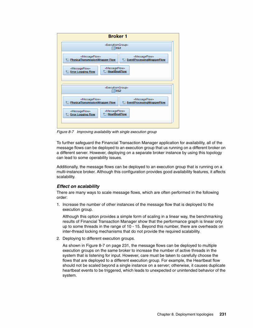
Figure 8-7 Improving availability with single execution group
To further safeguard the Financial Transaction Manager application for availability, all of the message flows can be deployed to an execution group that us running on a different broker on a different server. However, deploying on a separate broker instance by using this topology can lead to some operability issues.
Additionally, the message flows can be deployed to an execution group that is running on a multi-instance broker. Although this configuration provides good availability features, it affects scalability.
Effect on scalabilityThere are many ways to scale message flows, which are often performed in the following order:
1. Increase the number of other instances of the message flow that is deployed to the execution group.
Although this option provides a simple form of scaling in a linear way, the benchmarking results of Financial Transaction Manager show that the performance graph is linear only up to some threads in the range of 10 - 15. Beyond this number, there are overheads on inter-thread locking mechanisms that do not provide the required scalability.
2. Deploying to different execution groups.
As shown in Figure 8-7 on page 231, the message flows can be deployed to multiple execution groups on the same broker to increase the number of active threads in the system that is listening for input. However, care must be taken to carefully choose the flows that are deployed to a different execution group. For example, the Heartbeat flow should not be scaled beyond a single instance on a server; otherwise, it causes duplicate heartbeat events to be triggered, which leads to unexpected or unintended behavior of the system.
Chapter 8. Deployment topologies 231

3. Deploying to different broker.
When the capacity of a server is exhausted, more instances of the flows can be deployed to a broker that is running on a different server. However, in such cases, the Financial Transaction Manager database for both of the brokers must be the same. Having different databases for different brokers has a negative effect on the operability of the solution.
The use of a multi-instance broker topology does not provide scalability because the second instance of the broker is always on standby. Moreover, scaling a multi-instance broker requires adding a minimum of two brokers for horizontal scaling.
Effect on operabilityOperability refers to the ease of designing and managing the deployed solution. Although this topology is easier to deploy, it becomes increasingly more challenging to manage if there are more than one Financial Transaction Manager applications deployed. The ability to incrementally deploy new applications is limited with ability to shut down a specific application. Although WebSphere Message Broker allows starting and stopping of individual message flows, it is more difficult to selectively control individual flows.
Further, a bad flow that is using full resources in an execution group can cause the remainder of the flows in the same execution group to starve for resources, which means that one bad application can affect a good application that is deployed in the same execution group.
Multiple execution group deploymentWith this topology, the message flows can be split across multiple execution groups in WebSphere Message Broker. Typically, physical transmission wrapper flows and event processing wrapper flows are deployed to separate execution groups. Heart beat and error logging flows are deployed to a separate execution group or combined with event processing wrapper flows, a shown in Figure 8-8.
Figure 8-8 Multiple execution group deployment topology
This topology often is chosen when there are many physical transmission flows in the solution or these flows are added in incremental manner.
Effect on availabilityBecause a particular message flow is deployed to a single execution group in this topology, it is prone to a single point of failure. However, because of multiple execution group deployment, the probability of overall solution failure is relatively low. For example, failure of the execution group that contains the event processing wrapper flow does not prevent physical transmission wrapper flows from processing the inbound requests. In such a case, event messages pile up on the event queue that is waiting to be processed. After this execution group is recovered, the event processing begins as usual.
232 Financial Transaction Manager Technical Overview
Therefore, to ensure availability by using this topology, the message flows must be deployed to another execution group on the same or different broker. By using this topology, different availability requirements for different flows are available.
Additionally, the message flows can be deployed to an execution group that is running on a multi-instance broker. Although this configuration provides good availability features, it affects scalability.
Effect on scalabilityScalability by using this topology is similar to the one described in “Effect on scalability” on page 231. However, this topology allows scaling of a physical transmission wrapper and event processing wrapper separately, which provides better control over resource usage. Scaling by using multiple execution groups on the same machine with large amounts of resources has no significant effect as compared to scaling on a separate server. However, It does affect availability and operability of the solution.
Effect on operabilityThis topology makes the deployment process complicated as message flows must be deployed to multiple execution groups. Also, corresponding message sets must be deployed to each execution group to enable Financial Transaction Manager to parse the message. However, from a maintenance perspective, this topology provides better control over types of flows as incremental deployments can be performed for both event processing wrappers (to add new actions and mappers) and physical transmission wrapper flows (to add new interfacing points)
Multi-application deploymentFinancial Transaction Manager supports deployment of multiple applications to the same runtime instance. This means that there are different physical transmission wrapper flows and event processing wrapper flows for each application that can be deployed to same broker instance. The multiapplication deployment topology provides isolation to these applications by deploying them to a separate execution group. For each application, you can use the topology that is described in “Deploy to a single execution group” on page 230.
Figure 8-9 on page 234 shows such a deployment topology.
Chapter 8. Deployment topologies 233

Figure 8-9 Multi-application deployment topology
Further, applications can be deployed to separate brokers with their own databases to achieve complete isolation, as shown in Figure 8-10.
Figure 8-10 Multi-application deployment with full separation
Effect on availabilityWith this topology, the availability of each application can be controlled separately. The key benefit of this topology is that availability of each application can be addressed in an independent manner.
234 Financial Transaction Manager Technical Overview

Effect on scalabilityThe scalability of this topology is similar to the one that is addressed in the previous topologies. Similar to availability, this topology allows addressing scalability requirements of each application in an independent manner.
Effect on operabilityThis topology provides strong operability of a solution. Each application can be deployed, started, and stopped separately without affecting the other. However, the deployment of such a solution is often complicated because there are multiple BAR files for multiple execution groups.
8.2.2 Database schema configuration
In this section, we describe the choice of single or multiple schemas for the Financial Transaction Manager database. This is different from single or multiple database instances as described in 8.1.2, “Database” on page 224. In this case, you can create the schemas on a single or multiple databases.
Single schema configurationWith this topology, there is only a single schema for the Financial Transaction Manager configuration and operational database. This schema hosts data for all of the deployed Financial Transaction Manager applications. This is the most commonly used pattern in Financial Transaction Manager. However, adding entire operational data might cause contention in indexes and tables over time. This topology provides the following benefits:
� A single OAC for all the applications because data is stored in a single schema.
� Operational data management is easier because data archival purging policies can be applied easily.
However, separation of data for multiple applications must be achieved by using security features of the OAC.
Multiple schema configurationWith this topology, multiple Financial Transaction Manager database schemas are created in same database instance or different database instances. This topology features the following key advantages:
� Distributed data for a single application reducing contention in tables and indexes.
The key problem in such cases is allocation of unique IDs for various transaction, physical transmission, and batch records in the Financial Transaction Manager database. It is critical to have unique ID across the databases to prevent conflicts, especially if multiple databases must be consolidated into a single data warehouse. Financial Transaction Manager allows allocating a range of IDs to a specific partition or database instance to avoid such conflicts. For more information, see the Financial Transaction Manager Information Center section Planning ID Management.
� Physical separation of transaction data of multiple applications
However, with this configuration, a single OAC cannot be used to view the entire operational data. Each schema has its own OAC instance that is deployed on WebSphere Application Server.
Chapter 8. Deployment topologies 235

8.2.3 Operations and Administration user interface
The OAC does not participate in transaction processing. Instead, it provides a technical view of Financial Transaction Manager operational data. Therefore, the non-functional requirements of this component are not critical. However, there might be a requirement to deploy multiple instances of the application if multiple schema or databases are deployed as part of the solution. For more information, see the Financial Transaction Manager Information Center by clicking Installing Installing the FTM Operations and Administration Console.
236 Financial Transaction Manager Technical Overview

Chapter 9. Patterns
In this chapter, we describe a set of patterns for Financial Transaction Manager. A pattern is an approach to the design and build process where areas of common functions are addressed separately. This results in common, reusable assets that architects and developers can use to provide acceleration and ensure consistency of design and build for several projects.
Each of the patterns in this chapter shows this approach as a design exercise following the Financial Transaction Manager methodology. Beginning with a description of a requirement, the pattern section reviews the design steps by using Rational Software Architect to produce a set of reusable design artifacts, such as sequence diagrams, lifecycle diagrams, and Finite State Machine diagrams. Where appropriate, the pattern describes variants or options and other patterns or artifacts on which the pattern relies.
This chapter includes the following topics:
� Creation of outbound message or file pattern� Routing, IBM Operational Decision Manager rules, and multiple targets pattern� Semantic validation pattern� Enrichment pattern� Transformation pattern� Debulking pattern� Bulking pattern� Store and release pattern� Starting external services pattern� Hosting services pattern� Collating information from several sources pattern� Scheduled activity pattern� Scheduled expectation pattern� Heartbeats monitoring (scheduling) pattern� Error handling and alerts patterning
9
© Copyright IBM Corp. 2014. All rights reserved. 237

9.1 Creation of outbound message or file pattern
This pattern describes how to produce an Outbound Message or File by using Financial Transaction Manager. It describes the steps and components that are involved and the scenario variants in getting Financial Transaction Manager to propagate a message to an endpoint.
Figure 9-1 shows a high-level use case for the Creation of outbound message or file pattern.
Figure 9-1 Creation of outbound message or file pattern use case
9.1.1 High-level description
A Financial Transaction Manager Transmission object is made up of the following hierarchy of logical objects:
� Fragment objects� Batch objects� Transaction objects
An outbound Transmission object is created through the calling of actions in Financial Transaction Manager to group a set of possible Fragments, Batches, and Transactions together by some set of criteria and associate them with a single Transmission object.
This pattern is supported by core Financial Transaction Manager flows and Generic Finite State Machines. For more information, see the “Application Programming” and “Appendix E. Generic Model” sections of the Financial Transaction Manager 2.1 Information Center.
238 Financial Transaction Manager Technical Overview

The use of the pattern relies on configuration data, such as Service Participants, Channels, Mapper data, Formats, and Value table entries (for more information, see the “Data Model Overview” section in the Financial Transaction Manager 2.1 Information Center), and mapper flows (for more information, see the Application Programming Mappers section of the Information Center).
Creation of the outbound objects, including the outbound Transmission, should be handled through the Persistence APIs that are supplied with Financial Transaction Manager. The use of these APIs can provide performance benefits in the form of multi-row inserts and in-lining optimizations where physical records are not written to the Financial Transaction Manager database that is based on configuration. For more information about the Database Persistence, see the Application Programming section of the Financial Transaction Manager 2.1 Information Center.
When the creation of the Transmission object is deemed complete, routing decisions can be made or worked out later to assign an outbound channel with which the Transmission is associated. When Outbound Fragments or Batches are used, for example, routing decisions must be made in advance of orchestrating outbound Physical Transmission.
When this object preparation step is complete, an event or events are raised to start the orchestration of the objects. The action that raises this event is application-specific but is usually the action that is tracking the completeness of the outbound objects. The event or events are picked up by the Generic Outbound Physical Transmission Finite State Machine. Then, by using the routing information, the Generic Outbound Finite State Machines orchestrate the sending of the Transmission object to an action (in WebSphere Message Broker) that handles the physical propagation of the Transmission object to an external endpoint. This propagation is accomplished by using an outbound mapper component that transforms the Transmission to a suitable format. This format is supported by the outbound channel configuration.
The following high-level scenarios are involved in this pattern:
� Single Transaction Transmission� Batch Transmission� Fragmented Transmission
Which scenario is used is determined by the hierarchy of the objects that are contained within the outbound Transmission. Each of these high-level scenarios has a successful, map-aborted, and send-failed variant to them.
Chapter 9. Patterns 239

Single Transaction TransmissionFigure 9-2 shows a successful outbound Single Transaction Transmission.
Figure 9-2 Single Transaction Transmission (Outbound)
The successful outbound Single Transaction Transmission flow includes the following steps:
1. A Financial Transaction Manager action creates an outbound transaction object in the Financial Transaction Manager database. This transaction object usually has an internal standard format (ISF) message that is associated with it (created or passed from an inbound transaction object).
2. When created, a “Transaction created” event is raised, sometimes with associated routing information included.
3. This event is processed and, for this scenario, the Generic Outbound Transaction Finite State Machine orchestrates starting the outbound mapper and passing the message to the transport-based WebSphere Message Broker subflow for propagation to the required endpoint.
4. If this step is successful, the outbound Transmission object is logged to the Financial Transaction Manager database in the Sent state.
240 Financial Transaction Manager Technical Overview

Figure 9-3 shows an unsuccessful Outbound Single Transaction Transmission where the mapping of the Outbound Transaction failed.
Figure 9-3 Single Transaction Transmission (Outbound), map aborted
The map aborted outbound Single Transaction Transmission flow includes the following steps:
1. A Financial Transaction Manager action creates an outbound transaction object in the Financial Transaction Manager database. This transaction object usually has an ISF message that is associated with it (created or passed from an inbound transaction object).
2. When created, a “Transaction created” event is raised, sometimes with associated routing information included.
3. This event is picked up by the Event Processing core component in Financial Transaction Manager, and by using the routing information that is provided in the event or routing information that is determined by the type of message that us involved, the message is propagated to the relevant outbound mapper.
4. The outbound mapper takes the ISF message that is associated with the transaction and attempts to transform it to the required external format (for more information about this process, see 9.5, “Transformation pattern” on page 318). This step fails and a Map Aborted event is raised.
5. The outbound Transmission object is logged to the Financial Transaction Manager database in an Error state.
Chapter 9. Patterns 241

6. The operator is notified by using the Financial Transaction Manager Operators and Administration Console (OAC) and is given the choice to Verify or Resend the Transmission.
7. If the operator verifies the Transmission, the Transmission stays in an error state.
8. If the operator chooses to resend the Transmission, it is changed to a Sending state and then routed to the outbound mapper again.
Figure 9-4 shows an unsuccessful Outbound Single Transaction Transmission where the sending of the Outbound Transaction failed.
Figure 9-4 Single Transaction Transmission (Outbound), send failed
The send failed outbound Single Transaction Transmission flow includes the following steps:
1. A Financial Transaction Manager action creates an outbound transaction object in the Financial Transaction Manager database. This transaction object usually has an ISF message that is associated with it (created or passed from an inbound transaction object).
2. When created, a “Transaction created” event is raised, sometimes with associated routing information included.
242 Financial Transaction Manager Technical Overview

3. This event is picked up by the Event Processing core component in Financial Transaction Manager, and by using the routing information that is provided in the event or routing information that is determined by the type of message that is involved, the message is propagated to the relevant outbound mapper.
4. The outbound mapper takes the ISF message that is associated with the transaction and transforms it to the required external format (for more information about this process, see 9.5, “Transformation pattern” on page 318).
5. The outbound external format message is then routed by using an action to the required endpoint. For more information about this process, see “Sending the transmission” on page 277.
6. If message is not sent, the outbound Transmission object is logged to the Financial Transaction Manager database in an Error state.
7. The operator is notified by using the Financial Transaction Manager OAC and is given the choice to Verify or Resend the Transmission.
8. If the operator verifies the Transmission, the Transmission stays in an error state.
9. If the operator chooses to resend the Transmission, it is changed to a Sending state and then routed to the outbound mapper again. Although this is the Send Failed scenario, the outbound mapper is started again because the reason for the failure might be because of an incorrect mapping. Because these “Send Failed” scenarios are so infrequent, the performance overhead in calling the mapper again is deemed insignificant.
Batch TransmissionFigure 9-5 on page 244 shows a successful outbound Batch Transmission.
Chapter 9. Patterns 243
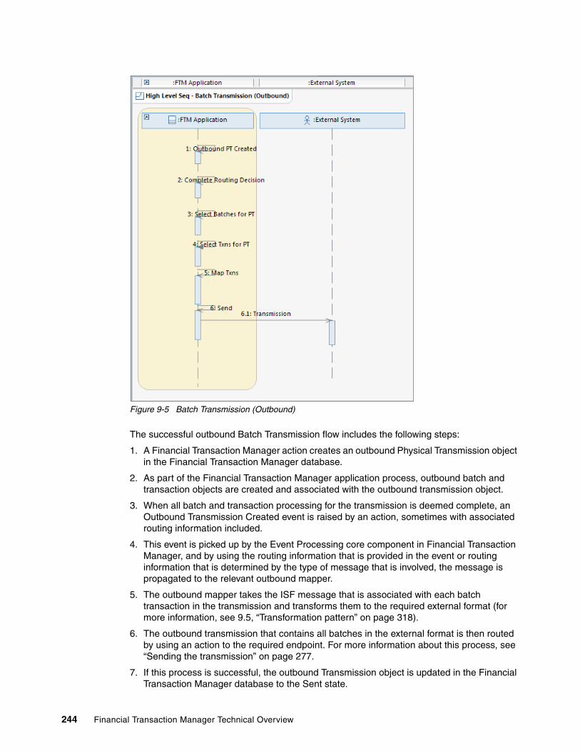
Figure 9-5 Batch Transmission (Outbound)
The successful outbound Batch Transmission flow includes the following steps:
1. A Financial Transaction Manager action creates an outbound Physical Transmission object in the Financial Transaction Manager database.
2. As part of the Financial Transaction Manager application process, outbound batch and transaction objects are created and associated with the outbound transmission object.
3. When all batch and transaction processing for the transmission is deemed complete, an Outbound Transmission Created event is raised by an action, sometimes with associated routing information included.
4. This event is picked up by the Event Processing core component in Financial Transaction Manager, and by using the routing information that is provided in the event or routing information that is determined by the type of message that is involved, the message is propagated to the relevant outbound mapper.
5. The outbound mapper takes the ISF message that is associated with each batch transaction in the transmission and transforms them to the required external format (for more information, see 9.5, “Transformation pattern” on page 318).
6. The outbound transmission that contains all batches in the external format is then routed by using an action to the required endpoint. For more information about this process, see “Sending the transmission” on page 277.
7. If this process is successful, the outbound Transmission object is updated in the Financial Transaction Manager database to the Sent state.
244 Financial Transaction Manager Technical Overview

Figure 9-6 shows an unsuccessful Outbound Batch Transmission where the mapping of the Outbound Transmission failed.
Figure 9-6 Batch Transmission (Outbound), map aborted
The map aborted outbound Batch Transmission flow includes the following steps:
1. A Financial Transaction Manager action creates an outbound Physical Transmission object in the Financial Transaction Manager database.
2. As part of the Financial Transaction Manager application process, outbound batch and transaction objects are created and are associated with the outbound transmission object.
3. When all batch and transaction processing for the transmission is deemed complete, an Outbound Transmission Created event is raised by an action, sometimes with associated routing information included.
4. This event is picked up by the Event Processing core component in Financial Transaction Manager, and by using the routing information that is provided in the event or routing information that is determined by the type of message that is involved, the message is propagated to the relevant outbound mapper.
5. The outbound mapper takes the ISF message that is associated with each batch transaction in the transmission and attempts to transform them to the required external format (for more information, see 9.5, “Transformation pattern” on page 318). This step fails and a Map Aborted event is raised.
Chapter 9. Patterns 245

6. The outbound Transmission object is logged to the Financial Transaction Manager database in an Error state.
7. The operator is notified by using the Financial Transaction Manager OAC and is given the choice to Verify or Resend the Transmission.
8. If the operator verifies the Transmission, the Transmission stays in an error state.
9. If the operator chooses to resend the Transmission, it is changed to a Sending state and then routed to the outbound mapper again.
Figure 9-7 shows an unsuccessful Outbound Batch Transmission where the sending of the Outbound Transmission failed.
Figure 9-7 Batch Transmission (Outbound), send failed
The send failed outbound Batch Transmission flow includes the following steps:
1. A Financial Transaction Manager action creates an outbound Physical Transmission object in the Financial Transaction Manager database.
2. As part of the Financial Transaction Manager application process, outbound batch and transaction objects are created and are associated with the outbound transmission object.
246 Financial Transaction Manager Technical Overview

3. When all batch and transaction processing for the transmission is deemed complete, an Outbound Transmission Created event is raised by an action, sometimes with associated routing information included.
4. This event is picked up by the Event Processing core component in Financial Transaction Manager, and by using the routing information that is provided in the event or routing information that is determined by the type of message that is involved, the message is propagated to the relevant outbound mapper.
5. The outbound mapper takes the ISF message that is associated with each batch transaction in the transmission and transforms them to the required external format (for more information, see 9.5, “Transformation pattern” on page 318).
6. The outbound transmission that contains all of the batches in the external format is then routed by using an action to the required endpoint. For more information about this process, see “Sending the transmission” on page 277.
7. If the sending of the message fails, the outbound Transmission object is logged to the Financial Transaction Manager database in an Error state.
8. The operator is notified by using the Financial Transaction Manager OAC and is given the choice to Verify or Resend the Transmission.
9. If the operator verifies the Transmission, the Transmission stays in an error state.
10.If the operator chooses to resend the Transmission, it is changed to a Sending state and then routed to the outbound mapper again. Although this is the Send Failed scenario, the outbound mapper is started again because the reason for the failure might be because an incorrect mapping. Because these Send Failed scenarios are so infrequent, the performance overhead in calling the mapper again is deemed insignificant.
Fragmented TransmissionFragmented Transmissions are used when you are dealing with large files; for example, those files that contain 100,000 transactions. The outbound Transmission can be broken up into many logical Fragments that can be processed in parallel in Financial Transaction Manager, which provides performance optimizations.
Chapter 9. Patterns 247

Figure 9-8 shows a successful outbound Fragmented Transmission.
Figure 9-8 Fragmented Transmission (Outbound)
The successful outbound Fragmented Transmission flow includes the following steps:
1. A Financial Transaction Manager action creates an outbound Physical Transmission object in the Financial Transaction Manager database.
2. As part of the Financial Transaction Manager application process, outbound fragment, batch, and transaction objects are created and associated with the outbound transmission object. The outbound fragment objects are created by a Fragmenter, which is application-specific (for example, a WebSphere Message Broker message flow and WebSphere Transformation Extender Map) and is tailored (based on message format) to break up the inbound message into fragments.
3. When all fragment, batch, and transaction processing for the transmission is deemed complete, an Outbound Transmission Created event is raised by an action, sometimes with associated routing information included.
4. This event is picked up by the Event Processing core component in Financial Transaction Manager and a check is performed to see whether the Transmission is composed of any Fragments.
5. For each Fragment in the Transmission, a Ready to Send Fragment event is raised.
248 Financial Transaction Manager Technical Overview

6. These events start the process of sending the Fragments to an outbound mapper where the Transaction internal standard format (ISF) messages that are contained within each Fragment are transformed to the required external format (for more information, see 9.5, “Transformation pattern” on page 318).
7. When successful, the outbound mapper then routes the outbound external format messages to a defragmenter.
8. The defragmenter checks if all Fragments within a Transmission were processed, and if so, routes the Transmission to the required endpoint.
9. The defragmenter raises a “Defragment complete” event and the outbound Transmission object is updated in the Financial Transaction Manager database to the Sent state.
Figure 9-9 shows an unsuccessful outbound Fragmented Transmission where the mapping of the Outbound Transmission failed.
Figure 9-9 Fragmented Transmission (Outbound), map abort
Chapter 9. Patterns 249

The map abort outbound Fragmented Transmission flow includes the following steps:
1. A Financial Transaction Manager action creates an outbound Physical Transmission object in the Financial Transaction Manager database.
2. As part of the Financial Transaction Manager application process, outbound fragment, batch, and transaction objects are created and are associated with the outbound transmission object.
3. When all fragment, batch, and transaction processing for the transmission is deemed complete, an Outbound Transmission Created event is raised by an action, sometimes with associated routing information included.
4. This event is picked up by the Event Processing core component in Financial Transaction Manager and a check is performed to see whether the Transmission is composed of any Fragments.
5. For each Fragment in the Transmission, a Ready to Send Fragment event is raised.
6. These events start the process of sending the Fragments to an outbound mapper where the Transaction ISFmessages that are contained within each Fragment are transformed to the required external format (for more information, see 9.5, “Transformation pattern” on page 318). This step fails and a Map Aborted event is raised.
7. The outbound Transmission object is updated in the Financial Transaction Manager database to an Error state.
8. The operator is notified by using the Financial Transaction Manager OAC and is given the choice to Verify or Resend the Transmission.
9. If the operator verifies the Transmission, the Transmission stays in an error state.
10.If the operator chooses to resend the Transmission, it is changed to a Sending state and processing resumes from step 5.
250 Financial Transaction Manager Technical Overview

Figure 9-10 shows an unsuccessful outbound Fragmented Transmission where the sending of the Outbound Transmission failed.
Figure 9-10 Fragmented Transmission (Outbound), send failed
The send failed outbound Fragmented Transmission flow includes the following steps:
1. A Financial Transaction Manager action creates an outbound Physical Transmission object in the Financial Transaction Manager database.
2. As part of the Financial Transaction Manager application process, outbound fragment, batch, and transaction objects are created and associated with the outbound transmission object.
3. When all fragment, batch, and transaction processing for the transmission is deemed complete, an Outbound Transmission Created event is raised by an action, sometimes with associated routing information included.
4. This event is picked up by the Event Processing core component in Financial Transaction Manager and a check is performed to see whether the Transmission is composed of any Fragments.
5. For each Fragment in the Transmission, a Ready to Send Fragment event is raised.
Chapter 9. Patterns 251

6. These events start the process of sending the Fragments to an outbound mapper where the Transaction ISFmessages contain within each Fragment are transformed to the required external format (for more information, see 9.5, “Transformation pattern” on page 318).
7. When successful, the outbound mapper then routes the outbound external format messages to a defragmenter.
8. The defragmenter checks if all Fragments within a Transmission were processed, and if so, routes the Transmission to the required endpoint.
9. If the defragmenter encounters an error during the sending of the Transmission, a Fragment Send Failed event is raised.
10.The outbound Transmission object is updated in the Financial Transaction Manager database to an Error state.
11.The operator is notified by using the Financial Transaction Manager OAC and is given the choice to Verify or Resend the Transmission.
12.If the operator verifies the Transmission, the Transmission stays in an error state.
13.If the operator chooses to resend the Transmission, it is changed to a Sending state and processing picks up from step 5 on page 251.
9.1.2 Objects and object relationships
Identifying Financial Transaction Manager Objects that are used in the pattern and the relationships between the objects is straightforward. A Transmission Object logically can be made up of Fragments, Batches, and Transactions, and physically be made up of Batches and Transactions.
Figure 9-11 shows the relationship between the objects in this pattern.
Figure 9-11 Creation of Outbound Message or File Object/Object Relationship
9.1.3 Detailed sequence diagram
The Detailed Sequence Diagrams that go along with the pattern highlight the interactions between the Financial Transaction Manager objects and components.
252 Financial Transaction Manager Technical Overview
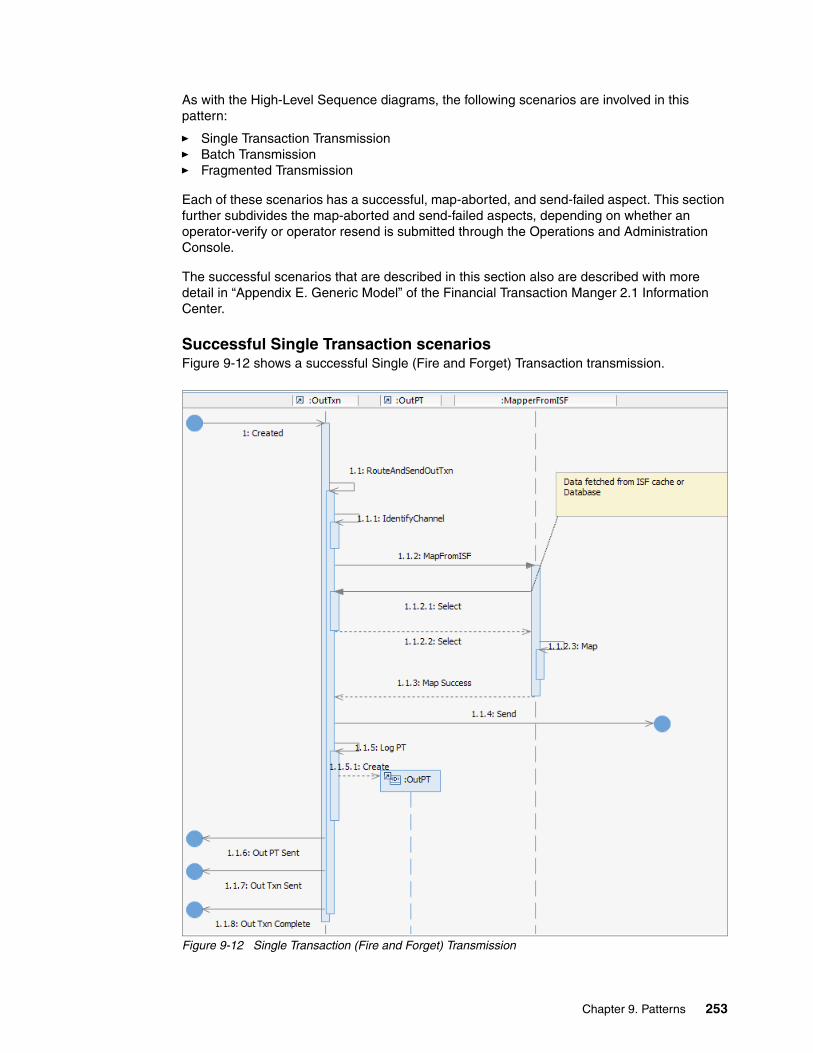
As with the High-Level Sequence diagrams, the following scenarios are involved in this pattern:
� Single Transaction Transmission� Batch Transmission� Fragmented Transmission
Each of these scenarios has a successful, map-aborted, and send-failed aspect. This section further subdivides the map-aborted and send-failed aspects, depending on whether an operator-verify or operator resend is submitted through the Operations and Administration Console.
The successful scenarios that are described in this section also are described with more detail in “Appendix E. Generic Model” of the Financial Transaction Manger 2.1 Information Center.
Successful Single Transaction scenariosFigure 9-12 shows a successful Single (Fire and Forget) Transaction transmission.
Figure 9-12 Single Transaction (Fire and Forget) Transmission
Chapter 9. Patterns 253

Figure 9-13 shows a successful Single (Expect Acknowledgement) Transaction transmission.
Figure 9-13 Single Transaction (Expect Acknowledgment) Transmission
“Map Abort” Single Transaction scenariosFor the following Detailed Sequence diagrams that show how error situations are handled, the Single Transaction (Fire and Forget) scenario is used. Error situations are handled identically when both transaction types are sent.
Figure 9-14 on page 255 shows Part 1 of 2 of an unsuccessful Single (Fire and Forget) Transaction transmission. In this scenario, the mapping fails and the operator verifies that the Transmission should remain in the Failed state.
254 Financial Transaction Manager Technical Overview
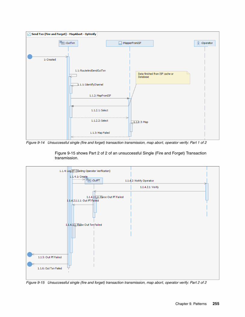
Figure 9-14 Unsuccessful single (fire and forget) transaction transmission, map abort, operator verify: Part 1 of 2
Figure 9-15 shows Part 2 of 2 of an unsuccessful Single (Fire and Forget) Transaction transmission.
Figure 9-15 Unsuccessful single (fire and forget) transaction transmission, map abort, operator verify: Part 2 of 2
Chapter 9. Patterns 255

Figure 9-16 shows Part 1 of 2 of an unsuccessful Single (Fire and Forget) Transaction transmission. In this scenario, the mapping fails and the operator signals that the Transmission should be resent.
Figure 9-16 Unsuccessful single (fire and forget) transaction transmission, map abort, operator resend: Part 1 of 2
256 Financial Transaction Manager Technical Overview

Figure 9-17 shows Part 2 of 2 of an unsuccessful Single (Fire and Forget) Transaction transmission. In this diagram, the mapping sequence where the transmission is mapped and sent to the external system is shortened to improve readability.
Figure 9-17 Unsuccessful Single (Fire and Forget) Transaction transmission, Map Abort, Operator Resend: Part 2 of 2
Chapter 9. Patterns 257

“Send Failed” Single Transaction scenariosFigure 9-18 shows Part 1 of 2 of an unsuccessful Single (Fire and Forget) Transaction transmission. In this scenario, the send fails and the operator verifies that the Transmission should remain in the Failed state.
Figure 9-18 Unsuccessful Single (Fire and Forget) Transaction transmission, Send Failed, Operator Verify: Part 1of 2
258 Financial Transaction Manager Technical Overview

Figure 9-19 shows Part 2 of 2 of an unsuccessful Single (Fire and Forget) Transaction transmission.
Figure 9-19 Unsuccessful Single (Fire and Forget) Transaction transmission, Send Failed, Operator Verify: Part 2 of 2
Chapter 9. Patterns 259

Figure 9-20 shows Part 1 of 2 of an unsuccessful Single (Fire and Forget) Transaction transmission. In this scenario, the send fails and the operator signals that the Transmission should be resent.
Figure 9-20 Unsuccessful Single (Fire and Forget) Transaction transmission, Send Failed, Operator Resend: Part 1of 2
260 Financial Transaction Manager Technical Overview

Figure 9-21 shows Part 2 of 2 of an unsuccessful Single (Fire and Forget) Transaction transmission. In this diagram, the mapping sequence where the transmission is mapped and sent to the external system was shortened to improve readability.
Figure 9-21 Unsuccessful Single (Fire and Forget) Transaction transmission, send failed, operator resend: Part 2 of 2
Chapter 9. Patterns 261

Successful Batch scenarioFigure 9-22 shows a successful Batch transmission.
Figure 9-22 Successful Batch transmission
262 Financial Transaction Manager Technical Overview

“Map Abort” Batch scenariosFigure 9-23 shows Part 1 of 2 of an unsuccessful Batch transmission. In this scenario, the mapping fails and the operator verifies that the Transmission should remain in the Failed state.
Figure 9-23 Unsuccessful Batch transmission, mapping failed, operator verify: Part 1of 2
Figure 9-24 shows Part 2 of 2 of an unsuccessful Batch transmission.
Figure 9-24 Unsuccessful Batch transmission, mapping failed, operator verify: Part 2 of 2
Chapter 9. Patterns 263

Figure 9-25 shows Part 1 of 2 of an unsuccessful Batch transmission. In this scenario, the mapping fails and the operator signals that the Transmission should be resent.
Figure 9-25 Unsuccessful Batch transmission, mapping failed, operator resend: Part 1of 2
Figure 9-26 shows Part 2 of 2 of an unsuccessful Batch transmission.
Figure 9-26 Unsuccessful Batch transmission, mapping failed, operator resend: Part 2 of 2
264 Financial Transaction Manager Technical Overview

“Send Failed” Batch scenariosFigure 9-27 shows Part 1 of 2 of an unsuccessful Batch transmission. In this scenario, the send fails and the operator verifies that the Transmission should remain in the Failed state.
Figure 9-27 Unsuccessful Batch transmission, send failed, operator verify: Part 1of 2
Figure 9-28 shows Part 2 of 2 of an unsuccessful Batch transmission.
Figure 9-28 Unsuccessful Batch transmission, send failed, operator verify: Part 2 of 2
Chapter 9. Patterns 265

Figure 9-29 shows Part 1 of 2 of an unsuccessful Batch transmission. In this scenario, the send fails, and the operator signals that the Transmission should be resent.
Figure 9-29 Unsuccessful Batch transmission, send failed, operator resend: Part 1 of 2
Figure 9-30 shows Part 2 of 2 of an unsuccessful Batch transmission.
Figure 9-30 Unsuccessful Batch transmission, send failed, operator resend: Part 2 of 2
266 Financial Transaction Manager Technical Overview

Successful Fragmented scenarioFigure 9-31 shows Part 1 of 2 of a successful Fragmented transmission.
Figure 9-31 Successful Fragmented Transmission: Part 1 of 2
Figure 9-32 shows Part 2 of 2 of a successful Fragmented transmission.
Figure 9-32 Successful Fragmented Transmission: Part 2 of 2
Chapter 9. Patterns 267
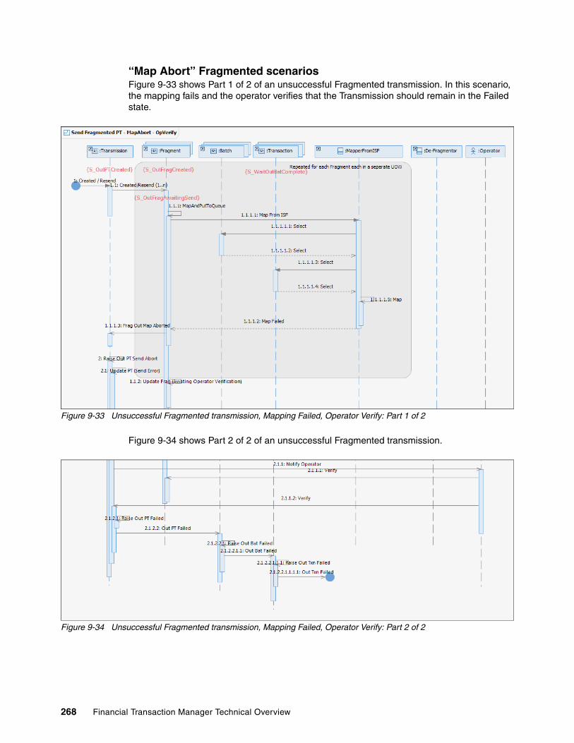
“Map Abort” Fragmented scenariosFigure 9-33 shows Part 1 of 2 of an unsuccessful Fragmented transmission. In this scenario, the mapping fails and the operator verifies that the Transmission should remain in the Failed state.
Figure 9-33 Unsuccessful Fragmented transmission, Mapping Failed, Operator Verify: Part 1 of 2
Figure 9-34 shows Part 2 of 2 of an unsuccessful Fragmented transmission.
Figure 9-34 Unsuccessful Fragmented transmission, Mapping Failed, Operator Verify: Part 2 of 2
268 Financial Transaction Manager Technical Overview

Figure 9-35 shows Part 1 of 2 of an unsuccessful Fragmented transmission. In this scenario, the mapping fails, and the operator signals that the Transmission should be resent.
Figure 9-35 Unsuccessful Fragmented transmission, Mapping Failed, Operator Resend: Part 1 of 2
Figure 9-36 shows Part 2 of 2 of an unsuccessful Fragmented transmission.
Figure 9-36 Unsuccessful Fragmented transmission, Mapping Failed, Operator Resend: Part 2 of 2
Chapter 9. Patterns 269
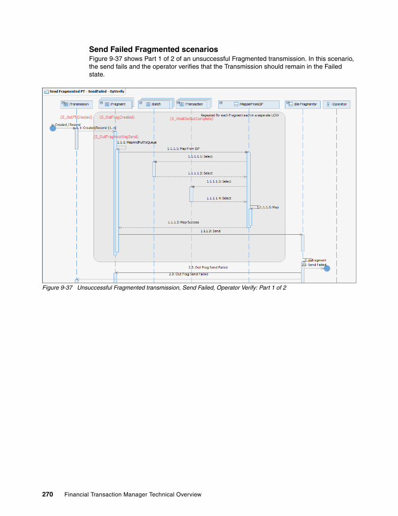
Send Failed Fragmented scenariosFigure 9-37 shows Part 1 of 2 of an unsuccessful Fragmented transmission. In this scenario, the send fails and the operator verifies that the Transmission should remain in the Failed state.
Figure 9-37 Unsuccessful Fragmented transmission, Send Failed, Operator Verify: Part 1 of 2
270 Financial Transaction Manager Technical Overview

Figure 9-38 shows Part 2 of 2 of an unsuccessful Fragmented transmission.
Figure 9-38 Unsuccessful Fragmented transmission, Send Failed, Operator Verify: Part 2 of 2
Chapter 9. Patterns 271

Figure 9-39 shows Part 1 of 2 of an unsuccessful Fragmented transmission. In this scenario, the send fails and the operator signals that the Transmission should be resent.
Figure 9-39 Unsuccessful Fragmented transmission, Send Failed, Operator Resend: Part 1 of 2
272 Financial Transaction Manager Technical Overview
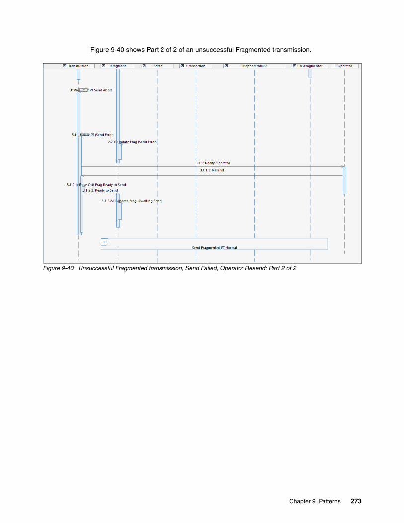
Figure 9-40 shows Part 2 of 2 of an unsuccessful Fragmented transmission.
Figure 9-40 Unsuccessful Fragmented transmission, Send Failed, Operator Resend: Part 2 of 2
Chapter 9. Patterns 273

9.1.4 Object lifecycle diagram
Figure 9-41 shows the Object lifecycle diagram for Outbound Transmissions. The diagram shows the various states that a Transmission object (Fragmented, Batch, or Transaction), transitions through, the events that cause those transitions, and actions that manipulate the Transmission.
Figure 9-41 Outbound Transmission Lifecycle diagram
For more information about the Object lifecycles of Fragments, Batches, and Transactions, see “Appendix E. Generic Model” of the Financial Transaction Manager 2.1 Information Center.
9.1.5 Finite state machine
For more information about the differences between the Object Lifecycle diagrams that were described in 9.1.4, “Object lifecycle diagram” on page 274 and their corresponding Finite State Machines, see “Appendix E. Generic Model” of the Financial Transaction Manager 2.1 Information Center.
9.1.6 Process highlights
In this section, we describe the steps that are involved in processing outbound transaction, batch, and fragmented transmissions. This assumes that the Financial Transaction Manager V2.1 Generic Finite State Machines are used to orchestrate the process. The descriptions that are used in this section are from the point of view of a single object for readability purposes (for example, one transaction, one batch, and one fragment). However, events are aggregated in Financial Transaction Manager and object selectors usually return more than one object, so these processes tend to affect multiple objects at the same time.
274 Financial Transaction Manager Technical Overview
For Single Transaction Transmissions, the following process highlights cause an outbound message or file to be transmitted:
1. Through application processing, an outbound transaction record is created in the Financial Transaction Manager database and the event E_TxnOutCreated is raised.
2. This event is picked up by the Financial Transaction Manager Event Processing component (WebSphere Message Broker message flow) and, by using metadata from the Generic Outbound Transaction Finite State Machine, calls the action A_RouteAndSendOutTxn.
3. This action checks if routing data is passed with the event in the form of PARTICIPANT or PARTICIPANT_RANK context. This context can be used to point to a Service Participant object to be used by the outbound transaction. The Service Participant has an outbound channel that is associated with it, and this is the outbound channel to which we want the transmission to be propagated.
4. If the PARTICIPANT context is not set, the action can also point to a Service Participant by performing a lookup of the Financial Transaction Manager database VALUE table by using the outbound transaction SUBTYPE and the VALUE table CATEGORY ROLE_FOR_TXN_TYPE and the PARTICIPANT_RANK if set in the context of the event.
5. When the outbound channel is identified through the Service Participant, the outbound mapper to use and the outbound transport method is known.
6. The action can then call the outbound mapper to transform the ISFmessage that is associated with the transaction to the external format that is required by the channel.
7. The outbound transport method on the channel (for example, WebSphere MQ, FILE, HTTP) is used by the EndOutboundMapper component of the outbound mapper as a means of routing the transformed message to a message flow that handles the physical propagation of the message to an external endpoint. This is handled by a RouteToLabel node in the EndOutboundMapper component, so this functionality is extensible by adding a custom transport method on the outbound channel that matches a Label node in a deployed message flow. For more information, see “Sending the transmission” on page 277.
8. When the message is physically propagated successfully by the message flow that is handling this process, an E_OutTxnSent event is raised to progress the outbound transaction orchestration, the outbound transmission object is created in the S_OutPTSent state (if it was not created earlier by the application), and an E_OutPTSent event is raised to progress the outbound transmission orchestration (if the transmission was created earlier by the application).
9. If the message cannot be physically propagated for any reason, the message flow that is handling the physical propagation creates the outbound transmission in the S_OutPTAwaitingSend state (if it was not created earlier by the application), and an E_OutPTSendFailed event is raised to progress the outbound transmission orchestration (which move the transmission to the S_OutPTSendError state and notifies the operator).
For more information about these processes, see the “Designing Applications” section in the Financial Transaction Manager 2.1 Information Center.
For Batch Transmissions, the following process highlights cause an outbound message or file to be transmitted:
1. Through application processing, an outbound batch record with associated outbound transaction records is created in the Financial Transaction Manager database and an event is raised to indicate as such. The application should also coordinate the creation of the outbound transmission that is associated with the batch in the S_OutPTCreated state, and as part of that creation, the outbound channel to use should be determined.
Chapter 9. Patterns 275

2. These is no Generic Outbound Batch Finite State Machine that is provided with the Financial Transaction Manager Core components, so one must be created to orchestrate the outbound batch process. This Finite State Machine transitions on the event that is raised and must check when all batches for an outbound transmission are complete and the outbound transmission is ready for physical propagation.
3. When the outbound transmission is ready, the Finite State Machine raises an E_PTOutCreated event.
4. This event is picked up by the Financial Transaction Manager Event Processing component (WebSphere Message Broker message flow) and, by using metadata from the Generic Outbound Physical Transmission Finite State Machine, calls the action A_MapAndPutPTToQueue.
5. As part of the object selector for the Outbound Physical Transmission Finite State Machine, the outbound channel identifier for the transmission is returned. The A_MapAndPutPTToQueue action can use this to determine the outbound mapper to call.
6. Processing continues as before with the Single Transaction description that was described detailed earlier in this section.
7. The created Outbound Batch Finite State Machine can transition on the E_OutPTSent event that was raised by the Generic Outbound Physical Transmission Finite State Machine to progress outbound batch orchestration. The Outbound Batch Finite State Machine can then orchestrate the raising of outbound batch complete events to progress outbound transaction orchestration (the Generic Outbound Transaction Finite State Machine is not used for outbound Batch Transaction processing).
For Fragmented Transmissions, the following process highlights cause an outbound message or file to be transmitted:
� As with the Batch Transmission case, through application processing, outbound fragments (which are created in the S_OutFragCreated state), and associated batch and outbound transaction records are created in the Financial Transaction Manager database. The application should also coordinate the creation of the outbound transmission (which are created in the S_OutPTCreated state) that are associated with the fragments. As part of that creation, the outbound channel to use should be determined. This outbound channel should point to a defragmenter component, such as the one that was used in the Fragmentation Sample (for more information, see Financial Transaction Manager 2.1 Information Center Appendix F).
� When a Fragment is ready for transmission, an E_OutFragReadyToSend event is raised that triggers a transition in the Generic Outbound Fragment Finite State Machine, which calls the A_MapAndPutFragToQueue action.
� As part of the object selector for the Generic Outbound Fragment Finite State Machine, the outbound channel identifier for the fragment is returned. The A_MapAndPutFragToQueue action can use this to determine the outbound mapper to call.
� The outbound mapper retrieves all the ISFmessages that are associated with the fragment and transforms them to the external format that is associated with the outbound channel. When complete, the outbound mapper then routes the transformed message to the defragmenter, as pointed to by the outbound channel.
Note: Although Queue is included in the name of this action, this naming is used for all transport types, not only for message queues.
276 Financial Transaction Manager Technical Overview

� As used in the Fragmentation Sample application, the defragmenter puts the transformed fragment to a FileOutput node. This node has a “Stage in mqsitransit directory and move to output directory on Finish File” property, which means the file is not written until all the fragments are de-fragmented. After the fragment is successfully put to the FileOutput node, the defragmenter raises an E_OutFragSent event.
� This event triggers a transition in two Finite State Machines: a transition in the Generic Outbound Fragment Finite State Machine to move the fragment object to a S_OutFragSent state, and a transition in the Generic Outbound Physical Transmission Finite State Machine that calls the action A_UpdateFragCounter, which checks whether all fragments for the transmission were processed.
� After this action confirms that all fragments for the transmission were processed, it raises an E_AllFragSent event, which transitions the transmission to a S_AllFragSent state.
� As the defragmenter puts the last fragment to the FileOutput node, it raises an E_DefragComplete event.
� The E_DefragComplete event also triggers a transition in two Finite State Machines. It triggers a transition in the Generic Outbound Physical Transmission Finite State Machine that raises the E_OutPTSent event and moves the transmission object to a S_OutPTSent state. It also triggers a transition in the Generic Outbound Fragment Finite State Machine that raises the E_OutFragComplete event and moves the fragment object to a S_OutFragComplete state.
� As before, the Outbound Batch Finite State Machine can transition on the E_OutPTSent event that was raised by the Generic Outbound Physical Transmission Finite State Machine to progress outbound batch orchestration. The Outbound Batch Finite State Machine can then orchestrate the raising of outbound batch complete events to progress outbound transaction orchestration.
Sending the transmissionA key concept in this pattern is the actual sending of the physical message to its final endpoint, whether it be a WebSphere MQ queue, file on a file system, or web service. This process is done in an extensible way to facilitate more endpoint protocols and is described in this section.
One of two Generic Actions is used in the sending of a physical outbound message, A_RouteAndSendOutTxn or A_MapAndPutPTToQueue. These actions are functionally similar to A_RouteAndSendOutTxn being used for single transactions and A_MapAndPutPTToQueue being used for transmissions that contain batches. The exception to this is when resending single transaction transmissions when A_MapAndPutPTToQueue is also used. The layout of both message flows is identical.
Figure 9-42 shows the layout of the A_MapAndPutPTToQueue action message flow.
Figure 9-42 A_MapAndPutPTToQueue
Chapter 9. Patterns 277

When an outbound message is ready for transmission, one of the actions are called. The mapper name of the mapper to be used to transform the ISFmessage to the necessary outbound format is retrieved from the outbound channel definition and assigned as a destination label for the RouteToLabel node to use to route the outbound message.
Figure 9-43 shows a portion of the esql code that is used in the action.
Figure 9-43 A_MapAndPutPTToQueue esql code snippet
The transport method is also retrieved from the outbound channel definition and is appended to a hardcoded MapperOutReturn_ value and stored in the MapperReturnLabelName portion of the environment for later use. The message is then routed to the outbound mapper. After the ISF transformation is complete, the EndOutboundMapper component of the mapper is called.
Figure 9-44 shows the EndOutboundMapper component message flow.
Figure 9-44 EndOutboundMapper
This flow uses the MapperReturnLabelName value that was set earlier to assign a destination label for the RouteToLabel node in the EndOutboundMapper component to use to route the outbound message.
Figure 9-45 shows a portion of the ESQL that was used in this component.
Figure 9-45 EndOutboundMapper esql code snippet
The MapperReturnLabelName matches to a label that is defined in the OutboundTransmissionHandler message flow (for channel transports of WebSphere MQ, FILE, or HTTP), which is included in the FTM Generic Model Actions project or matches to a label that is defined in a message flow that is bespokely created as part of the application.
278 Financial Transaction Manager Technical Overview

Figure 9-46 shows the OutboundTransmissionHandler message flow that is supplied with the FTM Generic Model Actions project.
Figure 9-46 OutboundTransmissionHandler message flow
In the case of a message flow that was created to handle transport protocols other than WebSphere MQ, FILE, or HTTP, the flow starts with a label node (as shown in Figure 9-46) with the label name set to MapperOutReturn_ and with the alternative transport protocol that is defined on the outbound channel appended.
The following label nodes are used in the OutboundTransmissionHandler message flow:
� MapAndPutPTToQueue_Success � MapAndPutPTToQueue_Failed
These label nodes are included as hooks for any bespoke transport-based message flows to return to after success or failure of the message transmission.
Chapter 9. Patterns 279

9.1.7 Pattern interaction
Each of the subpatterns within this section (Transaction, Batch, and Fragment) can be extensively incorporated into any larger process that includes outbound message handling. In this section, some examples of this some of the Detailed Sequence diagrams are references that were described for other patterns in this chapter. For more information about these scenarios and the diagrams, see “Appendix E. Generic Model” of the Financial Transaction Manager 2.1 Information Center.
Figure 9-47 shows how the Single Transaction (Fire and Forget) Transmission Detailed Sequence diagram can be referenced into a larger process, which shows the interactions with the Financial Transaction Manger Application and an External System.
Figure 9-47 Outbound Single Transaction (No Response)
280 Financial Transaction Manager Technical Overview

Figure 9-48 shows how this pattern can be integrated with the Debulking and Bulking patterns in a larger Batch process, which shows the interactions with the Financial Transaction Manger Application and an External System.
Figure 9-48 Batch Pattern Interaction
Figure 9-49 on page 282 shows how the Fragmented Transmission Detailed Sequence diagram can be referenced into a larger process, which shows the interactions with the Financial Transaction Manger Application and an External System.
Chapter 9. Patterns 281

Figure 9-49 Outbound Fragments
9.2 Routing, IBM Operational Decision Manager rules, and multiple targets pattern
In this section, we describe the pattern that routes transactions to their destinations by using the integration points within Financial Transaction Manager.
The destination for a transaction can be identified by the following components:
� Attributes of its data� Business defined rules in IBM Operational Decision Manager� Defaulted by Financial Transaction Manager
Figure 9-50 on page 283 shows the use case for this pattern.
282 Financial Transaction Manager Technical Overview

Figure 9-50 Routing high-level use case
9.2.1 High-level description
Transactions that are processed by Financial Transaction Manager and identified for transmission to an external application, network, and so on, must be associated with the outbound channel that was defined for that application.
This identification can be done based on data within the transaction. A payment transaction (for example, as defined by the transaction subtype) can be defaulted to a payment gateway. It can also be identified by interaction with an external business rules solution (for example, IBM Operational Decision Manager), which returns the outputs that are required for the transaction type.
In Financial Transaction Manger, integration to external systems is defined by the following Financial Transaction Manager objects, configuration data, and the relationship between them:
� The Format configuration data defines the data structure that is required by the external application.
� The Mapper, which defines how the transaction should be transformed for the ISF to the format that is required by the external application. This makes use of the format configuration data.
� The Involved Party configuration data, which describes the external application within Financial Transaction Manager.
� The Channel Object that defines how data is transmitted to the external application. This brings together the Format, the Mapper, and the Involved Party. The channel also defines the transport mechanism that the outbound message is written; for example folder, message queue, and web service. The channel does not identify messages within Financial Transaction Manager that it should transmit, only the physical delivery of the data.
Chapter 9. Patterns 283
� The Service Participant Object represents an interface from and to Financial Transaction Manager and the attributes that link messages within Financial Transaction Manager to the channels that are used to transmit or receive them. The Service Participant Object also defines the role and rank of the service participant; for example, the role that service participant plays within the Service (Payment Gateway, General Ledger Application, and so on). These roles can be used to link transactions to the service participant; for example, payment transactions can be linked to the Payment Gateway service participant. Rank is used if more than one service participant plays the same role; for example, service participants with the Payment Gateway role, one for international payments and one for local payments (in this case, Rank can be used to distinguish between them).
� The Financial Transaction Manager Value table can be used to hold variables that link the transaction type to the Service Participant Role.
IBM Operational Decision Manager can be used to show routing rules to business users, with which they can maintain and create rules to decide the destinations of transactions.
In this pattern, we consider the following use cases:
� Identify outbound destinations from within Financial Transaction Manager� Identify outbound destinations by using Operational Decision Manager
284 Financial Transaction Manager Technical Overview

Figure 9-51 shows the high-level description for the first use case.
Figure 9-51 High-level description for routing to external application
IBM Operational Decision Manager can be used to externalize the routing decisions so that business users can maintain where transactions are routed; for example, routing certain product types to a credit check application.
Chapter 9. Patterns 285

The high-level description diagram for this use case is shown in Figure 9-52.
Figure 9-52 High-level description for routing to external application with business rules
In both of these use cases, multiple output destinations can be identified and the process that is repeated for each.
286 Financial Transaction Manager Technical Overview

9.2.2 Objects and object relationships
The object relationship diagram for this pattern is shown in Figure 9-53.
Figure 9-53 Object/object relationship diagram for routing
9.2.3 Detailed sequence diagram
The detailed sequence diagram for this pattern shows the interaction between the Financial Transaction Manager objects, the master transaction, the outgoing transaction, and the transmission.
The pattern features the following use cases:
� Identify destinations by code or variables.� Identify destinations by business rules in IBM Operational Decision Manager.
The detailed sequence diagram for the first use case is shown in Figure 9-54.
Figure 9-54 Routing by transaction attributes or variables
Chapter 9. Patterns 287

Figure 9-55 shows the detailed sequence diagram for routing by using Operational Decision Manager.
Figure 9-55 Routing by using Operational Decision Manager
288 Financial Transaction Manager Technical Overview

9.2.4 Object lifecycle diagram
Figure 9-56 shows an example of an object lifecycle diagram for an outbound transaction for this pattern.
Figure 9-56 Routing Object Lifecycle Diagram
The lifecycle diagram in Figure 9-56 shows the states that an object goes through as it is being sent. In the situation where more than one destination was identified, this lifecycle is repeated with different outbound transmissions being created and sent.
In addition, there might be the requirement to wait for acknowledgements from the external application before transaction continues to be processed. This issue is not covered in this pattern because this pattern deals only with identifying destinations.
9.2.5 Finite state machine
The following types of finite state machines that can be defined for this pattern are available:
� Routing that is decided within Financial Transaction Manager
� Routing that is decided by using external business rules that are defined in IBM Operational Decision Manager
The finite state machine examples that are presented in this section are concerned with incoming transactions to Financial Transaction Manager.
Chapter 9. Patterns 289

The finite state machine for the first scenario is simpler and shown in Figure 9-57.
Figure 9-57 Finite state machine for routing within Financial Transaction Manager
290 Financial Transaction Manager Technical Overview
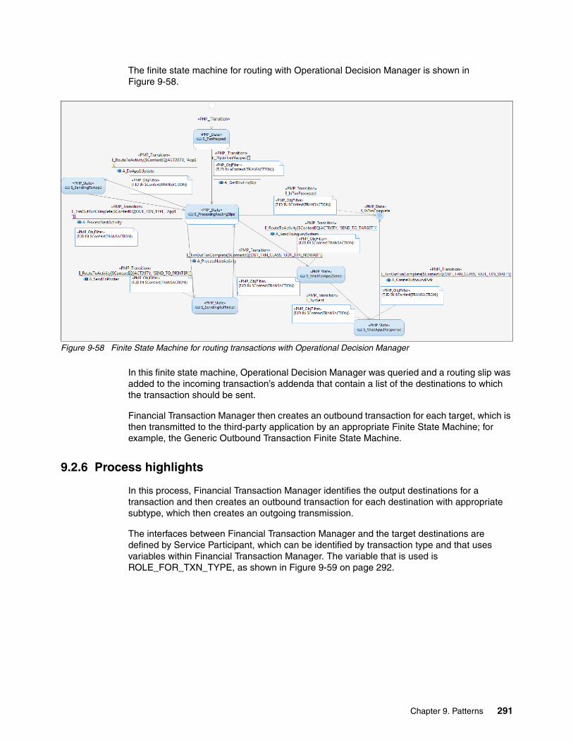
The finite state machine for routing with Operational Decision Manager is shown in Figure 9-58.
Figure 9-58 Finite State Machine for routing transactions with Operational Decision Manager
In this finite state machine, Operational Decision Manager was queried and a routing slip was added to the incoming transaction’s addenda that contain a list of the destinations to which the transaction should be sent.
Financial Transaction Manager then creates an outbound transaction for each target, which is then transmitted to the third-party application by an appropriate Finite State Machine; for example, the Generic Outbound Transaction Finite State Machine.
9.2.6 Process highlights
In this process, Financial Transaction Manager identifies the output destinations for a transaction and then creates an outbound transaction for each destination with appropriate subtype, which then creates an outgoing transmission.
The interfaces between Financial Transaction Manager and the target destinations are defined by Service Participant, which can be identified by transaction type and that uses variables within Financial Transaction Manager. The variable that is used is ROLE_FOR_TXN_TYPE, as shown in Figure 9-59 on page 292.
Chapter 9. Patterns 291

Figure 9-59 Configuration Values for role for transaction types
This table matches the transaction type (subtype); for example PAYMENT_INS, to the Service Participant role, PAYMENTGW. Figure 9-60 shows the Service Participant details.
In Figure 9-60, the value of PAYMENTGW does not display because values in the Classification Values table overwrite the PAYMENTGW code with the Payment Gateway value.
Figure 9-60 Service Participant Definitions
The entry is shown in Figure 9-61.
Figure 9-61 Classification Item view for Service Participant roles
The master transaction creates outbound transactions of the appropriate type as it follows its lifecyle, which is sent to the destination by using the channel that is defined in the Service Participant.
292 Financial Transaction Manager Technical Overview

Figure 9-60 on page 292 also shows the Rank of the Service Participant, which can be used to distinguish between Service Participants with the same Role.
It is also possible to use business rules (such as those that are defined in IBM Operational Decision Manager) to identify the destinations for a transaction. In this case, artifacts (such as decision tables) can be created, as shown in Figure 9-62.
Figure 9-62 Example of a decision table in Operational Decision Manager
In this example, the destinations that a transaction is sent to is identified by the original message type, currency, and receiver bank. These destinations are added to the master transaction object’s addenda and are used to identify that outbound transactions that must be created for these destinations.
9.2.7 Pattern interaction
This pattern interacts with patterns that deal with transmitting transactions to external applications, such as those that are described in 9.1, “Creation of outbound message or file pattern” on page 238, 9.7, “Bulking pattern” on page 348, and 9.5, “Transformation pattern” on page 318.
9.3 Semantic validation pattern
When a transaction is received by Financial Transaction Manager, it is validated to ensure that it has the correct syntax. This syntactical validation is performed as the message is parsed within the inbound mapper and checks that the data matches the defined format; for example, the WebSphere Message Broker Domain/Message Set and the WebSphere Transformation Extender maps. This also includes validating that the data values match the defined data types, such as the numeric values for numeric data types and the correct delimiters or record lengths. In the case of XML data that is received, the validation ensures that the document is well-formed.
Chapter 9. Patterns 293

The Financial Transaction Manager Channel also might be configured by using a channel property to cause other validation to occur; for example, validating the message against the message set or schema constraints to check the presence of elements against cardinality constraints (such as optional/mandatory/repeating), or value ranges. Similarly, validation against message set or schema constraints might be configured as a channel property for outbound messages. This is a technical validation that ensures that the data is in the expected format, the mandatory fields are present, and the data within the fields conform to the field definitions.
Syntactical validation also occurs if the transactions are received within a file to ensure that the file format matches that defined, which ensures that all transactions in the file are of the format expected (for example SWIFT) or ensuring that the file delimiter is as defined.
However, it is common for financial organizations to require that the received transaction also passes validation that is defined by networks (such as SWIFT cross field validation), business rules (such as the customer is authorized to use a particular financial product), and so on.
Semantic rules for file validation can be used to verify that the data that is presented as part of a file is correct; for example, by ensuring the count and total value of transactions in a file or batch matches that of the header record. This type of semantic validation is performed against the ISF representation of the message and usually occurs near the beginning of a message’s lifecycle.
The semantic validation processes are defined as actions within the finite state machines and correspond to WebSphere Message Broker subflows where the process is defined. Semantic validation can be driven by the following components:
� Header or footer information within a file
� Data within the transaction; for example value date, currency
� Metadata of the transaction; for example originating customer or application
� Variable-driven or business-facing business rules; for example, by using IBM Operational Decision Manager
� Network defined rules; for example, SWIFT cross-field validation
Leading Practice: Semantic validation routines might need to be updated regularly; for example, in response to annual SWIFT changes. Therefore, they should be implemented in a modular, non-intrusive way. This decreases the effect on the overall solution, which decreases regression testing, and so on.
294 Financial Transaction Manager Technical Overview
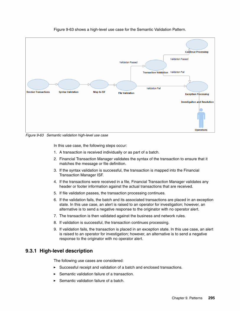
Figure 9-63 shows a high-level use case for the Semantic Validation Pattern.
Figure 9-63 Semantic validation high-level use case
In this use case, the following steps occur:
1. A transaction is received individually or as part of a batch.
2. Financial Transaction Manager validates the syntax of the transaction to ensure that it matches the message or file definition.
3. If the syntax validation is successful, the transaction is mapped into the Financial Transaction Manager ISF.
4. If the transactions were received in a file, Financial Transaction Manager validates any header or footer information against the actual transactions that are received.
5. If file validation passes, the transaction processing continues.
6. If the validation fails, the batch and its associated transactions are placed in an exception state. In this use case, an alert is raised to an operator for investigation; however, an alternative is to send a negative response to the originator with no operator alert.
7. The transaction is then validated against the business and network rules.
8. If validation is successful, the transaction continues processing.
9. If validation fails, the transaction is placed in an exception state. In this use case, an alert is raised to an operator for investigation; however, an alternative is to send a negative response to the originator with no operator alert.
9.3.1 High-level description
The following use cases are considered:
� Successful receipt and validation of a batch and enclosed transactions.
� Semantic validation failure of a transaction.
� Semantic validation failure of a batch.
Chapter 9. Patterns 295

� Successful receipt and validation of a batch and enclosed transactions by business rules that are published in WebSphere Operational Decision Manager.
� Semantic validation failure transactions by business rules that are published in WebSphere Operational Decision Manager.
Each of these use cases is started by the receipt of a file or transaction from a client or application. The file or transactions are received into Financial Transaction Manager and, if in a batch within a file, debulked into individual transactions. For more information, see 9.6, “Debulking pattern” on page 338.
Successful receipt and validation of a file and transactionsThis use case considers the receipt of a file that contains one or more transactions that are successfully validated by the semantic validation rules.
The semantic validation rules can be defined within Financial Transaction Manager artifacts and use external data sources, such as databases and web services. In addition, variables that are defined within Financial Transaction Manager can be used within the validation routines. Business facing routing rules that are defined within Operational Decision Manager can also be used to perform semantic validation.
Figure 9-64 shows the high-level process flow for this use case.
Figure 9-64 High-level process diagram, successful processing
This process flow shows the following steps:
1. The file is received and the Receive and Debulk Pattern processes the file and creates the batch and transaction objects.
2. The transactions are validated against the semantic validation rules and are marked as awaiting the successful validation of the batch object. As each transaction is processed, counters can be updated, which are used as part of batch validation; including transaction count, total amount, and so on. The validation rules can be defined within Financial Transaction Manager or within Operational Decision Manager.
296 Financial Transaction Manager Technical Overview

3. When the transactions are successfully validated, the batch object is then validated.
4. When the batch passes validation, the individual transactions continue to be processed.
Semantic validation failure of transactionsIn this use case, the file and transactions are received and successfully pass syntactical validation. The batch is debulked into individual transactions, which are validated against the semantic validation rules.
In this use case, a transaction fails semantic validation and an alert is raised to inform an operator. The batch and its contained transactions are inter-related so that when a transaction within a batch fails validation, they both are shown in an alert state.
Figure 9-65 shows a high-level process flow that describes this use case.
Figure 9-65 High-level process diagram transaction validation fails
The following steps occur in this process flow:
1. The Receive and Debulk Pattern creates the Financial Transaction Manager transaction and batch objects.
2. The transactions are validated against the semantic validation rules and are marked as awaiting the successful validation of the batch object. As each transaction is processed, counters can be updated that are used as part of batch validation, including transaction count, total amount, and so on. The validation rules can be defined within Financial Transaction Manager or within Operational Decision Manager.
3. One or more transactions fail semantic validation and are placed in an alert state. As one or more transactions are in an alert state, the batch is also placed in an alert state.
4. When a validation failure occurs, an alert is raised to inform an operator that manual intervention is required to resolve the issue.
5. The operator investigates and resolves the validation failure, as described in 9.15, “Error handling and alerts patterning” on page 438.
Chapter 9. Patterns 297

In this use case, an alert is raised to the operator and processing is paused until the exception is resolved. However, alternative variations of this pattern can be implemented if one or more transactions fail validation, such as the batch or file can be rejected or the transactions that pass validation can continue processing.
Semantic validation failure of a batch In this use case, the file and transactions are received and successfully pass syntactical validation. However, the file fails semantic validation (for example, because of header information not matching with transactional data) or batch details are invalid because of business rules (for example, the file is not expected or allowed at reception time).
Figure 9-66 shows a high-level process flow that describing this use case.
Figure 9-66 High-level process diagram batch validation fails
The following steps occur in this process flow:
1. The Receive and Debulk Pattern creates the Financial Transaction Manager transaction and batch objects.
2. The transactions are validated against the semantic validation rules and are marked as awaiting the successful validation of the batch object. As each transaction is processed, counters can be updated, which are used as part of batch validation, including transaction count, total amount, and so on. The validation rules can be defined within Financial Transaction Manager or Operational Decision Manager.
3. All transactions pass validation.
4. The batch fails validation and is placed in an alert state. When a validation failure occurs, an alert is raised to inform an operator that manual intervention is required to resolve the issue. The transactions that are associated with the batch also are placed in an alert state.
5. The operator investigates and resolves the validation failure, as described in 9.15, “Error handling and alerts patterning” on page 438.
298 Financial Transaction Manager Technical Overview
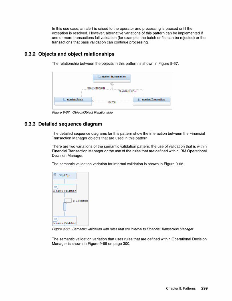
In this use case, an alert is raised to the operator and processing is paused until the exception is resolved. However, alternative variations of this pattern can be implemented if one or more transactions fail validation (for example, the batch or file can be rejected) or the transactions that pass validation can continue processing.
9.3.2 Objects and object relationships
The relationship between the objects in this pattern is shown in Figure 9-67.
Figure 9-67 Object/Object Relationship
9.3.3 Detailed sequence diagram
The detailed sequence diagrams for this pattern show the interaction between the Financial Transaction Manager objects that are used in this pattern.
There are two variations of the semantic validation pattern: the use of validation that is within Financial Transaction Manager or the use of the rules that are defined within IBM Operational Decision Manager.
The semantic validation variation for internal validation is shown in Figure 9-68.
Figure 9-68 Semantic validation with rules that are internal to Financial Transaction Manager
The semantic validation variation that uses rules that are defined within Operational Decision Manager is shown in Figure 9-69 on page 300.
Chapter 9. Patterns 299

Figure 9-69 Semantic validation with rules in IBM Operational Decision Manager
The detailed sequence diagram for successful semantic validation of a transaction and batch is shown in Figure 9-70.
Figure 9-70 Successful semantic validation of a transaction and batch
300 Financial Transaction Manager Technical Overview

The detailed sequence diagram for a transaction failing semantic validation is shown in Figure 9-71.
Figure 9-71 Transaction fails semantic validation
Chapter 9. Patterns 301
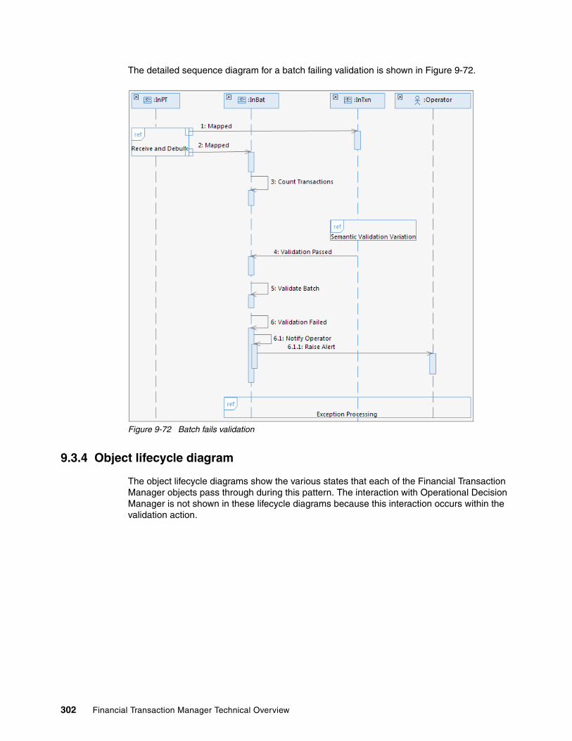
The detailed sequence diagram for a batch failing validation is shown in Figure 9-72.
Figure 9-72 Batch fails validation
9.3.4 Object lifecycle diagram
The object lifecycle diagrams show the various states that each of the Financial Transaction Manager objects pass through during this pattern. The interaction with Operational Decision Manager is not shown in these lifecycle diagrams because this interaction occurs within the validation action.
302 Financial Transaction Manager Technical Overview

Figure 9-73 shows the object lifecycle diagram for a transaction.
Figure 9-73 Object lifecycle for a successfully validated transaction
Batch object lifecycle diagramThe object lifecycle diagram for a batch object is shown in Figure 9-74.
Figure 9-74 Object lifecycle for a successfully validated batch
9.3.5 Finite state machine
In Financial Transaction Manager, the finite state machine models the transactions process flow, including each state that the transaction might go through, the events that cause the change of state, and the actions that are started when that change occurs.
Semantic validation is a pattern that can be added to any finite state machine as part of a larger validation process or stand-alone.
Chapter 9. Patterns 303

In this pattern, there are two finite state machines that interact; for example, the result of the batch validation having a direct effect on the transaction’s finite state machine.
Figure 9-75 shows the finite state machine that, in this pattern, defines the process flow through which a batch object follows, from mapping into the internal standard format to passing or failing semantic validation.
Figure 9-75 Finite State Machine for Batch processing
There are various interaction points from the transaction finite state machine that are used to update counters in the batch objects. These counters can be used as part of the batch validation process.
Note: When a batch fails validation, it raises the event E_BatchValFail. This also triggers an action in the transaction’s finite state machine
304 Financial Transaction Manager Technical Overview

Figure 9-76 shows the transaction’s finite state machine for this pattern, from mapping to the internal state machine to passing or failing validation. If a transaction is validated correctly, it waits for the batch validation to be completed successfully. If the batch validation fails, the transactions that are associated with that batch are placed in an alert state.
Figure 9-76 Finite State Machine for Transactions
Chapter 9. Patterns 305

9.3.6 Process highlights
This pattern is concerned with the semantic validation of batches and transactions in the following modes:
� Semantic validation rules and decisions that are defined with the validation action
� Semantic validation rules and decisions that are defined within Operational Decision Manager
The following Financial Transaction Manager objects are used in this pattern:
� Batch object� Transaction object
In addition to these Financial Transaction Manager objects, the following messages are created:
� Operational Decision Manager request message� Operational Decision Manager response message� Alert
9.3.7 Pattern interaction
The semantic validation of batches and messages can interact with various other patterns; for example, in 9.1, “Creation of outbound message or file pattern” on page 238, this pattern can be used to ensure that the message to be sent out is valid, or in 9.8, “Store and release pattern” on page 358 to ensure that the transactions be released are still valid.
This pattern can be used with incoming and outgoing messages to ensure that the transactions are valid for processing within an organization and for the outgoing network.
9.4 Enrichment pattern
Financial Transaction Manager can receive transactional data from many data sources, applications, or client files. It is common that the transaction that is received must be enhanced and enriched to allow for processes later in its lifecycle. This can be because of data that is required for downstream mandatory fields is missing from the source message or that other data is required because optional or conditional fields are present.
This pattern describes the means that the transaction can be enriched by supplementing the received transaction with more data. Figure 9-77 shows the use case for this pattern.
Figure 9-77 Transaction Enrichment use case
In this use case, a transaction was received by Financial Transaction Manager and is being processed. The transaction requires more data added to it for downstream processing or to be sent to an external application and is enriched in a number of modes.
306 Financial Transaction Manager Technical Overview

In all modes, this enrichment is carried out by a WebSphere Message Broker subflow with an ESQL or Java compute node, an external call node (for example, SOAP or WebSphere MQ) or by a specialized node; for example, the Operational Decision Manager Decision Service node.
The transaction is required to be enriched by business rules that were published to Operational Decision Manager; for example, customer-specific details.
A WebSphere Message Broker subflow is started that creates and sends a request message as expected by Operational Decision Manager. The published rules are triggered and the resulting data is sent back to Financial Transaction Manager in a response message. The data from this response message is then used to enrich the transaction.
After enrichment, the transaction continues to be processed
9.4.1 High-level description
In this pattern, the following modes of enrichment are considered:
� Enrichment that uses coding� Enrichment that uses external data� Enrichment that uses business rules that are defined in Operational Decision Manager
These modes can be combined within a transactions lifecycle such that a coded enrichment can be followed by a look up to a database for further enrichment. This depends on requirements.
Enrichment that uses codingIn this enrichment mode, the transaction is enriched within Financial Transaction Manager by programming the addition of new data or by accessing Financial Transaction Manager variables, as shown in Figure 9-78.
Figure 9-78 High-level interaction diagram for enrichment by using coding
In this enrichment mode, there is little or no interaction with other applications or data sources. The transaction is enriched directly by coding; for example, for data that never or rarely changes or by referencing Financial Transaction Manager variables.
Chapter 9. Patterns 307
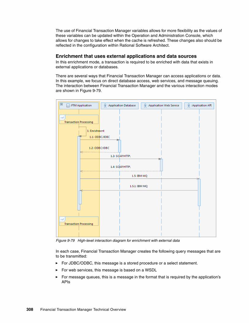
The use of Financial Transaction Manager variables allows for more flexibility as the values of these variables can be updated within the Operation and Administration Console, which allows for changes to take effect when the cache is refreshed. These changes also should be reflected in the configuration within Rational Software Architect.
Enrichment that uses external applications and data sourcesIn this enrichment mode, a transaction is required to be enriched with data that exists in external applications or databases.
There are several ways that Financial Transaction Manager can access applications or data. In this example, we focus on direct database access, web services, and message queuing. The interaction between Financial Transaction Manager and the various interaction modes are shown in Figure 9-79.
Figure 9-79 High-level interaction diagram for enrichment with external data
In each case, Financial Transaction Manager creates the following query messages that are to be transmitted:
� For JDBC/ODBC, this message is a stored procedure or a select statement.
� For web services, this message is based on a WSDL
� For message queues, this is a message in the format that is required by the application’s APIs
308 Financial Transaction Manager Technical Overview

For enrichment by direct database connectivity or synchronous web services, the transaction can be enriched immediately and processing is not paused. Web services can be synchronous or asynchronous, depending on how long the process they start takes or how reliable they are. Asynchronous web services require state management with Financial Transaction Manager and can be thought of as analogous to IBM WebSphere MQ messaging. This pattern focuses on synchronous web service interactions.
For enrichment by messages queues, such as IBM WebSphere MQ, this is an asynchronous communication method and the transaction must wait before processing continues. In addition, a new transaction and physical transmission is created to show that a message was transmitted from Financial Transaction Manager and it is waiting for a response. This can be used to monitor response times from the third-party application. When the response arrives, the transaction can be enriched with the data.
Enrichment that uses Operational Decision ManagerWhen integrated with Financial Transaction Manager, IBM Operational Decision Manager allows business users to control and alter rules that are used for validation, routing, enrichment, and so on, which reduces the dependence on IT development.
Financial Transaction Manager is delivered with the capability to integrate with Operational Decision Manager as part of the core delivery, as shown in Figure 9-80.
Figure 9-80 High-level interaction diagram for enrichment with external data
In this mode of enrichment, Financial Transaction Manager creates the expected request message for the Operational Decision Manager rule set within the WebSphere Message Broker action subflow. This message then is transmitted by using the Operational Decision Manager Decision Service Node to Operational Decision Manager synchronously.
The response message from Operational Decision Manager includes any enrichment data that might be added to the transaction.
Chapter 9. Patterns 309

9.4.2 Objects and object relationships
Table 9-1 lists the Financial Transaction Manager objects that are created in this pattern.
Table 9-1 Objects
Figure 9-81 shows the object relationships.
Figure 9-81 Enrichment, object/object relationship
Enrichment by direct database connectivity or by using Operational Decision Manager does not create Financial Transaction Manager objects because they are carried out programmatically within the enrichment action subflow in WebSphere Message Broker.
9.4.3 Detailed sequence diagram
The enrichment pattern acts, in most modes, only on the transaction object within Financial Transaction Manager. Enrichment that uses messaging queues to an application API is different because this occurs in an asynchronous manner and the transaction is placed in paused state until the response is received.
Figure 9-82 on page 311 shows the detailed sequence diagram for enrichment by code or Financial Transaction Manager variables.
Physical Transmission Transaction
Application API Request Application API Request
Application API Response Application API Response
310 Financial Transaction Manager Technical Overview

Figure 9-82 Detailed Sequence Diagram enrichment by using code or variables
In this mode, there are no objects that are created during the enrichment and no external applications are queried.
Enrichment by direct database access or web services are similar in that the communication is synchronous. Enrichment by direct database connectivity is shown in Figure 9-83.
Figure 9-83 Detailed Sequence Diagram enrichment by using database connectivity
In this mode, Financial Transaction Manager connects to a stored procedure or issues a SELECT statement that returns a value or a record set. This call or statement is created as part of the enrichment action within WebSphere Message Broker. The data is then used to enrich the transaction.
Chapter 9. Patterns 311

Figure 9-84 shows enrichment by using a web service call.
Figure 9-84 Enrichment that uses a synchronous web service call
In this mode, Financial Transaction Manager calls a web service that is based on the services WSDL. This is part of the enrichment action subflow that is defined in WebSphere Message Broker. Enrichment that uses business rules in Operational Decision Manager is similar to enrichment that uses a web service, as shown in Figure 9-85.
Figure 9-85 Enrichment that uses Operational Decision Manager
Financial Transaction Manager calls the Operational Decision Manager Rules Execution Service with a message that is constructed according to the specifications of the rules set. The WebSphere Message Broker enrichment action subflow uses the specialized Operational Decision Service node.
Enrichment that uses an application’s API by a message queue (for example, WebSphere MQ) is different from the modes that were described previously. In this mode, a message is transmitted to the application and Financial Transaction Manager holds the transaction in a waiting state until the reply from the application is received, as shown in Figure 9-86 on page 313.
312 Financial Transaction Manager Technical Overview

Figure 9-86 Enrichment using an Application API call
This mode causes the creation of Financial Transaction Manager objects, the Application API transaction object, and the Application API transmission object. The transaction object is a representation of the API request in Financial Transaction Manager’s internal standard format while the physical transmission represents the actual data that is sent to the application.
9.4.4 Object lifecycle diagram
The object lifecycle diagrams in this pattern are straight forward. Enriching by code, direct database connectivity, or web services have the same lifecycle, as shown in Figure 9-87.
Figure 9-87 Object lifecycle for synchronous enrichment
These modes of enrichment have only one state and one action that is associated with their lifecycle in this pattern.
Chapter 9. Patterns 313

Figure 9-88 shows the object lifecycle for asynchronous enrichment.
Figure 9-88 Object lifecycle for asynchronous enrichment
In this enrichment mode, the transaction passes through two other states as the transaction sends then awaits the response from the external application. Multiple enrichment methods might be required, which combines these modes into a more complex lifecycle.
314 Financial Transaction Manager Technical Overview
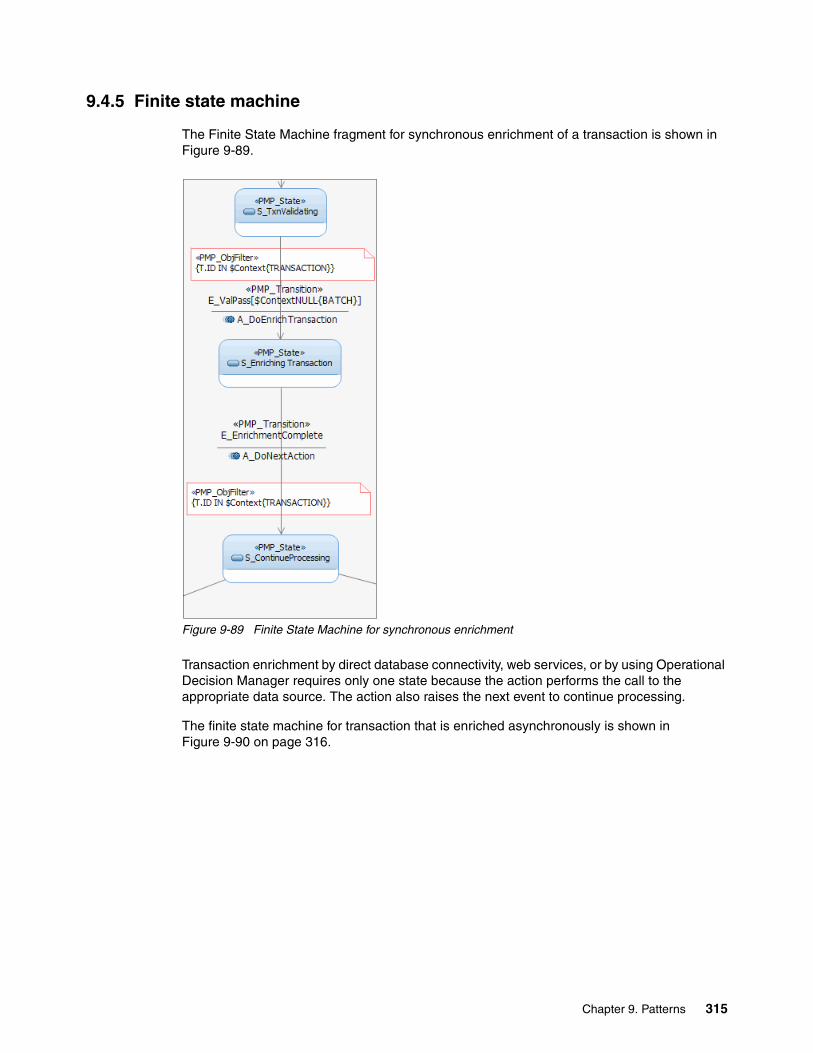
9.4.5 Finite state machine
The Finite State Machine fragment for synchronous enrichment of a transaction is shown in Figure 9-89.
Figure 9-89 Finite State Machine for synchronous enrichment
Transaction enrichment by direct database connectivity, web services, or by using Operational Decision Manager requires only one state because the action performs the call to the appropriate data source. The action also raises the next event to continue processing.
The finite state machine for transaction that is enriched asynchronously is shown in Figure 9-90 on page 316.
Chapter 9. Patterns 315
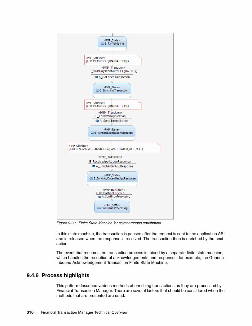
Figure 9-90 Finite State Machine for asynchronous enrichment
In this state machine, the transaction is paused after the request is sent to the application API and is released when the response is received. The transaction then is enriched by the next action.
The event that resumes the transaction process is raised by a separate finite state machine, which handles the reception of acknowledgements and responses; for example, the Generic Inbound Acknowledgement Transaction Finite State Machine.
9.4.6 Process highlights
This pattern described various methods of enriching transactions as they are processed by Financial Transaction Manager. There are several factors that should be considered when the methods that are presented are used.
316 Financial Transaction Manager Technical Overview

Coded or variable-based enrichmentWhen you are enriching data by using code or Financial Transaction Manager variables, consider the following points:
� For code-based enrichment, the regularity of changes to the enrichment data should be low as the WebSphere Message Broker flow must be changed and compiled. A new BAR file must be deployed and tested.
� For variable-based enrichment, the data that is held by the variables can be changed as required; however, where the data is placed within the transaction is still controlled by the action subflow. Financial Transaction Manager variables also are loaded into memory when the Financial Transaction Manager message flow starts. This cache must be refreshed manually or automatically before the variable’s new data can be used.
Direct database connectivityConnecting directly to a database is often a quick and easy method for extracting data from an application’s database table. However, the following points should be considered:
� This method requires an understanding of the application that is being connected to the database, which might create dependencies between the enrichment code and the database.
� Database changes might cause the enrichment process to become invalid (for example, changes to fields, table names) or schemas unless a stored procedure is used and is kept updated with the database changes.
� Database user names and passwords must be maintained
It is a better practice to connect to an external application by using its published APIs or web services when they exist.
Web servicesEnriching transactions by using web services is a common method for extracting data from applications and multiple tables. The message that is required by the web service is defined by the WSDL and this must be included in the deployed BAR file.
Enrichment that uses Operational Decision ManagerThe IBM Operational Decision Server node is included within the Financial Transaction Manager Package and allows WebSphere Message Broker flows to seamlessly integrate into the rules environment.
The Financial Transaction Manager action subflow, which calls the rules environment, is required to build a message that is based on the DecisionService schema. This XML message contains a request message that is based on the Business Object Model that was defined within Operational Decision Manager.
This message is transmitted to the Operational Decision Manager Rules Execution Server, which returns the results of the rules. These results can then be used to enrich the message, populating fields, updating existing data, and so on.
Consideration should be given to which type of enrichment data is maintained by business users as opposed to technical users; for example, it might not be appropriate to give access to data that can affect the technical routing of the transaction.
Chapter 9. Patterns 317

Application APIApplication APIs are a more mature method of extracting data in an asynchronous method. The time that is taken for the application to return the enrichment data should be considered because it can affect on-time critical transactions.
Because transactions are paused while they wait on the reply from the application, a secondary process must be in place to reactivate the payments and add the data manually if the application is unavailable or the process is too slow.
9.4.7 Pattern interaction
Data enrichment can occur at any point in the flow or at multiple places in the flow. For example, the transaction can be enriched after validation and then enriched later on for a target application.
9.5 Transformation pattern
This pattern describes how Financial Transaction Manager can be used to accept inbound physical transmissions in the form of a single transaction, batch, or a fragment and map it to ISF transactions by using Financial Transaction Manager core components and generic Process Inbound Transmission Finite State Machine and associated actions and events. The ISF transactions can then be processed by Financial Transaction Manager to meet functional requirements.
On the outbound side, the pattern demonstrates how Financial Transaction Manager can be used to transform ISF transactions into physical transmissions of single transaction or batch by using generic Outbound Transaction Finite State Machine and associated actions and events.
The pattern also describes how transformation failures can be handled in a generic way for most of the scenarios.
Figure 9-91 depicts the high-level use case diagram for transformation pattern.
Figure 9-91 Transformation pattern use case diagram
318 Financial Transaction Manager Technical Overview

9.5.1 High-level description
In Financial Transaction Manager, the inbound physical transmission can be of three types: Transaction, Batch, or Fragment. When Financial Transaction Manager receives either of these transmissions, it must map individual transactions that are present in the physical transmission to ISF by using the inbound mapper component for lifecycle processing. When the mapping completes, Financial Transaction Manager raises multiple events, depending on the following mapping status:
� Success: No known mapping errors were detected.
� Failure: Mapping errors were detected, but one or more transactions that were created by the inbound mapper are in valid state. In this case, the business process must define the recovery mechanism.
� Aborted: Mapping errors were detected and none of the transactions are in valid state. In this case, operations personnel are needed to verify the transmission.
On the outbound side, ISF transactions must be mapped to an outbound physical transmission that contains single or a batch of transactions by using the outbound mapper component. Similar to inbound processing, Financial Transaction Manager raises multiple events on completion of outbound mapping, depending on the status of mapping.
The state management for inbound and outbound processing is carried out in the Financial Transaction Manager Generic Finite State Machine Process Inbound Transmission and Outbound Transaction.
This pattern includes the following key high-level scenarios:
� Inbound Single Transaction� Inbound Batch Transmission� Inbound Fragment Transmission� Outbound Transaction
These scenarios have Success, Failure, and Aborted aspects to them.
Successful inbound single transaction scenarioFigure 9-92 shows a successful inbound single transaction scenario.
Figure 9-92 Successful inbound single transaction
Chapter 9. Patterns 319

Figure 9-92 on page 319 shows the following process:
1. The client sends a single transaction message to Financial Transaction Manager. The client in this case can be an initiator of a transaction or a system that is sending a response to a request.
2. Financial Transaction Manager logs the transaction with the Physical Transmission Arrived state and maps the transaction to ISF by using an inbound mapper that is configured for the channel.
3. When complete, the ISF transaction is logged to Financial Transaction Manager operation database with the Transaction Mapped state.
4. A Transaction mapped event is raised with associated routing information.
5. This event is picked up by the Event Processing core component in Financial Transaction Manager and the transaction is processed further according to Finite State Machine configuration.
Aborted inbound single transaction scenarioFigure 9-93 shows a single transaction where ISF mapping is aborted.
Figure 9-93 Aborted inbound single transaction
Figure 9-93 shows the following process:
1. The client sends a single transaction message to Financial Transaction Manager. In this case, the client can be an initiator of a transaction or a system that is sending a response to a request.
2. Financial Transaction Manager logs the transaction with the Physical Transmission Arrived state and maps the transaction to ISF by using an inbound mapper that is configured for the channel. This step fails.
3. A Transaction Mapping Aborted event is raised with the associated routing information.
4. This event is picked up by the Event Processing core component in Financial Transaction Manager and the state of inbound physical transmission is changed to Physical Transmission Mapping Failed. It is then assigned to operations personnel to investigate who can cancel the transaction processing.
320 Financial Transaction Manager Technical Overview

Failed inbound single transaction scenarioFigure 9-94 shows a single transaction in which ISF mapping reported a failure.
Figure 9-94 Failed inbound single transaction
Figure 9-94 shows the following process:
1. The client sends a single transaction message to Financial Transaction Manager. In this case, the client can be an initiator of a transaction or a system that is sending a response to a request.
2. Financial Transaction Manager logs the transaction with the Physical Transmission Arrived state and maps the transaction to ISF by using an inbound mapper that is configured for the channel. This step reports the mapping status as Failure.
3. In this case, the ISF transaction is logged to the Financial Transaction Manager operation database with the Transaction Mapped state.
4. A Transaction Mapping Failed event is raised with the associated routing information.
5. This event is picked up by the Event Processing core component in Financial Transaction Manager and the transaction is processed further according to Finite State Machine configuration.
Chapter 9. Patterns 321

Successful inbound batch scenarioFigure 9-95 shows a successful inbound batch scenario.
Figure 9-95 Successful inbound batch
Figure 9-95 shows the following process:
1. The client sends a batch that contains multiple transactions to Financial Transaction Manager. In this case, the client can be an initiator of a transaction or a system that is sending a response to a request.
2. Financial Transaction Manager logs the batch with the Physical Transmission Arrived state and maps each transaction in the batch to ISF by using an inbound mapper that is configured for the channel.
3. When complete, Financial Transaction Manager logs a batch record with a status Batch Mapped to the operational database.
4. Each transaction in the batch is logged to the Financial Transaction Manager operation database with the Transaction Mapped state.
5. A Batch Mapped event is raised with associated routing information.
6. This event is picked up by the Event Processing core component in Financial Transaction Manager and the transaction is processed further according to Finite State Machine configuration.
322 Financial Transaction Manager Technical Overview
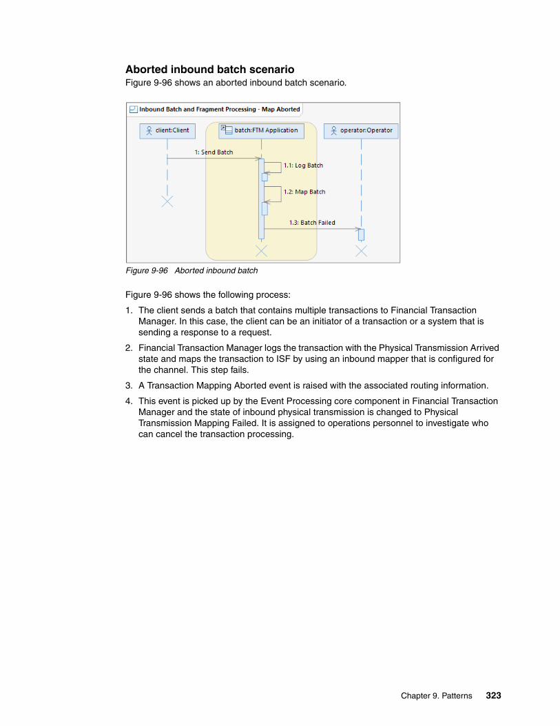
Aborted inbound batch scenarioFigure 9-96 shows an aborted inbound batch scenario.
Figure 9-96 Aborted inbound batch
Figure 9-96 shows the following process:
1. The client sends a batch that contains multiple transactions to Financial Transaction Manager. In this case, the client can be an initiator of a transaction or a system that is sending a response to a request.
2. Financial Transaction Manager logs the transaction with the Physical Transmission Arrived state and maps the transaction to ISF by using an inbound mapper that is configured for the channel. This step fails.
3. A Transaction Mapping Aborted event is raised with the associated routing information.
4. This event is picked up by the Event Processing core component in Financial Transaction Manager and the state of inbound physical transmission is changed to Physical Transmission Mapping Failed. It is assigned to operations personnel to investigate who can cancel the transaction processing.
Chapter 9. Patterns 323

Failed inbound batch scenarioFigure 9-97 shows a failed batch scenario.
Figure 9-97 Failed inbound batch
Figure 9-97 shows the following process:
1. The client sends a batch that contains multiple transactions to Financial Transaction Manager. In this case, the client can be an initiator of a transaction or a system that is sending a response to a request.
2. Financial Transaction Manager logs the batch with the Physical Transmission Arrived state and maps the transaction to ISF using an inbound mapper that is configured for the channel. This step reports the mapping status as “Failure”.
3. In this case, Financial Transaction Manager logs a batch record with a status Batch Mapped to the operational database.
4. Each transaction in the batch is logged to the Financial Transaction Manager operation database with the Transaction Mapped state.
5. A Batch Mapping Failed event is raised with the associated routing information.
6. This event is picked up by the Event Processing core component in Financial Transaction Manager and the transaction is processed further according to Finite State Machine configuration.
324 Financial Transaction Manager Technical Overview

Successful inbound fragment scenarioFigure 9-98 shows a successful fragment scenario.
Figure 9-98 Successful inbound fragment
Figure 9-98 shows the following process:
1. The client sends a fragment that contains multiple transactions from one or more batches to Financial Transaction Manager. In this case, the client can be an initiator of a transaction or a system that is sending a response to a request.
2. Financial Transaction Manager logs the fragment as physical transmission with the Physical Transmission Arrived state and as a fragment with the Fragment Arrived state. It then maps the transaction to ISF by using an inbound mapper that is configured for the channel.
3. When complete, Financial Transaction Manager logs a batch record with a status Batch Mapped to the operational database.
4. Each transaction in the batch is logged to the Financial Transaction Manager operation database with the Transaction Mapped state.
5. A Fragment Mapped event is raised with associated routing information.
6. This event is picked up by the Event Processing core component in Financial Transaction Manager and the transaction is processed further according to Finite State Machine configuration.
Chapter 9. Patterns 325
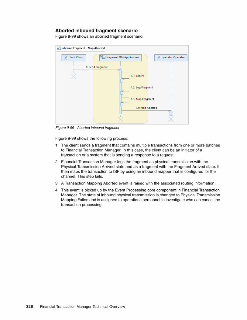
Aborted inbound fragment scenarioFigure 9-99 shows an aborted fragment scenario.
Figure 9-99 Aborted inbound fragment
Figure 9-99 shows the following process:
1. The client sends a fragment that contains multiple transactions from one or more batches to Financial Transaction Manager. In this case, the client can be an initiator of a transaction or a system that is sending a response to a request.
2. Financial Transaction Manager logs the fragment as physical transmission with the Physical Transmission Arrived state and as a fragment with the Fragment Arrived state. It then maps the transaction to ISF by using an inbound mapper that is configured for the channel. This step fails.
3. A Transaction Mapping Aborted event is raised with the associated routing information.
4. This event is picked up by the Event Processing core component in Financial Transaction Manager. The state of inbound physical transmission is changed to Physical Transmission Mapping Failed and is assigned to operations personnel to investigate who can cancel the transaction processing.
326 Financial Transaction Manager Technical Overview

Failed inbound fragment scenarioFigure 9-100 shows a failed fragment scenario.
Figure 9-100 Failed inbound fragment
Figure 9-100 shows the following process:
1. The client sends a fragment that contains multiple transactions from one or more batches to Financial Transaction Manager. In this case, the client can be an initiator of a transaction or a system that is sending a response to a request.
2. Financial Transaction Manager logs the fragment as a physical transmission with the Physical Transmission Arrived state and as a fragment with the Fragment Arrived state. It then maps the transaction to ISF by using an inbound mapper that is configured for the channel. This step reports the mapping status as “Failure”.
3. In this case, Financial Transaction Manager logs a batch record with a status Batch Mapped to the operational database.
4. Each transaction in the batch is logged to the Financial Transaction Manager operation database with the Transaction Mapped state.
5. A Fragment Mapping Failed event is raised with the associated routing information.
6. This event is picked up by the Event Processing core component in Financial Transaction Manager and the transaction is processed further according to Finite State Machine configuration.
Chapter 9. Patterns 327

Successful outbound transaction mapping scenarioFigure 9-101 shows a successful outbound transaction mapping scenario.
Figure 9-101 Successful outbound transaction mapping
Figure 9-101 shows the following process:
1. A Financial Transaction Manager action creates an outbound transaction object in the Financial Transaction Manager database.
2. When created, a Transaction created event is raised with the associated routing information.
3. This event is picked up by the Event Processing core component in Financial Transaction Manager. The message is propagated to the relevant outbound mapper by using the routing information that is provided in the event or routing information that is determined by the type of message that is involved.
4. The outbound mapper takes the ISF message that is associated with the transaction and transforms it to the required external format.
5. The outbound mapper logs the created physical transmission with the Outbound Physical Transmission Created state.
6. The mapper raises the Physical Transmission Created event with the associated routing information.
7. This event is picked up by the Event Processing core component in Financial Transaction Manager and the transaction is processed further according to Finite State Machine configuration.
328 Financial Transaction Manager Technical Overview

Outbound transaction mapping failure scenarioFigure 9-102 shows a failed outbound mapping for an outbound transaction. This scenario covers Failure and Aborted aspects.
Figure 9-102 Outbound transaction mapping failure
Figure 9-102 shows the following process:
1. A Financial Transaction Manager action creates an outbound transaction object in the Financial Transaction Manager database.
2. When created, a Transaction created event is raised with the associated routing information.
3. This event is picked up by the Event Processing core component in Financial Transaction Manager. The message is propagated to the relevant outbound mapper by using the routing information that is provided in the event or routing information that is determined by the type of message that is involved.
4. The outbound mapper takes the ISF message that is associated with the transaction and transforms it to the required external format. This step fails.
5. Financial Transaction Manager logs the error with the Outbound Physical Transmission Waiting for Operator state and assigns it to operation personnel.
Chapter 9. Patterns 329

9.5.2 Objects and object relationships
The Financial Transaction Manager objects that are identified and used in this pattern and their relationship with each other are shown in Figure 9-103.
Figure 9-103 Financial Transaction Manager object-to-object relationship
A transmission object can consist of a transaction, batch, or fragment. However, from the lifecycle perspective, a physical transmission is a transaction or a batch of transactions. Therefore, there is no direct dependency relationship between batch and fragment.
9.5.3 Detailed sequence diagram
The detailed sequence diagrams in this pattern demonstrate the interactions between the Financial Transaction Manager objects and components. Similar to high-level sequence diagrams, this pattern includes the following scenarios:
� Inbound Single Transaction� Inbound Batch Transmission� Inbound Fragment Transmission� Outbound Transaction
Each of these scenarios has a successful, map-aborted, and map-failed aspect to them. For more information about the successful scenarios that are described here, see “Appendix E. Generic Model” of the Financial Transaction Manger V2.1 Information Center.
330 Financial Transaction Manager Technical Overview

Inbound single transactionFigure 9-104 shows a successful log and map single transaction.
Figure 9-104 Log and Map Single Transaction
Figure 9-105 shows a scenario in which inbound mapper reports the map status as Aborted.
Figure 9-105 Log and Map Single Transaction: Map Aborted
In the case of an aborted map, no transaction object is created. The physical transmission object is moved to the Map Failed state S_InPTMapFailed and an operator is notified. The operator can cancel only the transmission that moves the physical transmission object to its final state S_InPTFailed.
This detail sequence diagram also applies to batch and fragment processing.
Chapter 9. Patterns 331
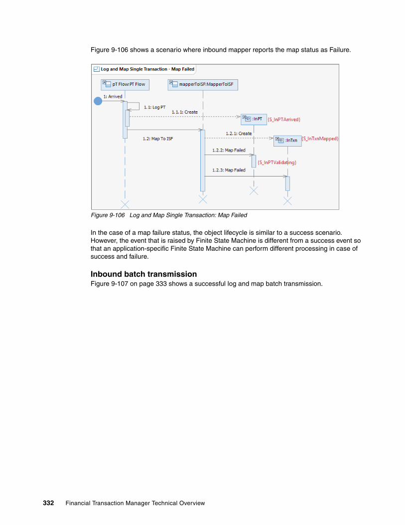
Figure 9-106 shows a scenario where inbound mapper reports the map status as Failure.
Figure 9-106 Log and Map Single Transaction: Map Failed
In the case of a map failure status, the object lifecycle is similar to a success scenario. However, the event that is raised by Finite State Machine is different from a success event so that an application-specific Finite State Machine can perform different processing in case of success and failure.
Inbound batch transmissionFigure 9-107 on page 333 shows a successful log and map batch transmission.
332 Financial Transaction Manager Technical Overview

Figure 9-107 Log and Map Batch transaction
Figure 9-108 shows a scenario in which inbound mapper reports the map status as Failure.
Figure 9-108 Log and Map Batch transaction: Map Failure
Chapter 9. Patterns 333

In the case of a map failure status, the object lifecycle is similar to a success scenario. However, the event that is raised by the Finite State Machine is different from a success event so that the application-specific Finite State Machine can perform different processing in case of success and failure. The generic Inbound Physical Transmission Finite State Machine does not differentiate between success and failure status of the map, which means the next state in both the cases is the same.
Inbound fragment transmissionFigure 9-109 shows a scenario of a successful inbound fragment transmission.
Figure 9-109 Log and Map Fragment transmission
Figure 9-110 on page 335 shows the scenario in which an inbound map reports the mappings status as failure.
334 Financial Transaction Manager Technical Overview

Figure 9-110 Log and Map Fragment: Map Failure
In the case of a map failure status, the object lifecycle is similar to a success scenario. However, the event that is raised by the Finite State Machine is different from a success event so that the application-specific Finite State Machine can perform different processing in case of success and failure. The generic Inbound Physical Transmission Finite State Machine does not differentiate between the success and failure status of the map, which means that the next state in both the cases is the same.
Outbound transactionFor more information about detailed sequence diagrams for outbound transaction mapping, see Section 9.1, “Creation of outbound message or file pattern” on page 238.
9.5.4 Object lifecycle diagram
The object lifecycle diagram that is shown in this section shows a portion of entire object lifecycle that is specific to the transformation pattern. For more information, see the Financial Transaction Manager Information Center’s “Appendix E. Generic Model” section.
Figure 9-111 on page 336 show the lifecycle of the physical transmission object that is involved in this pattern.
Chapter 9. Patterns 335
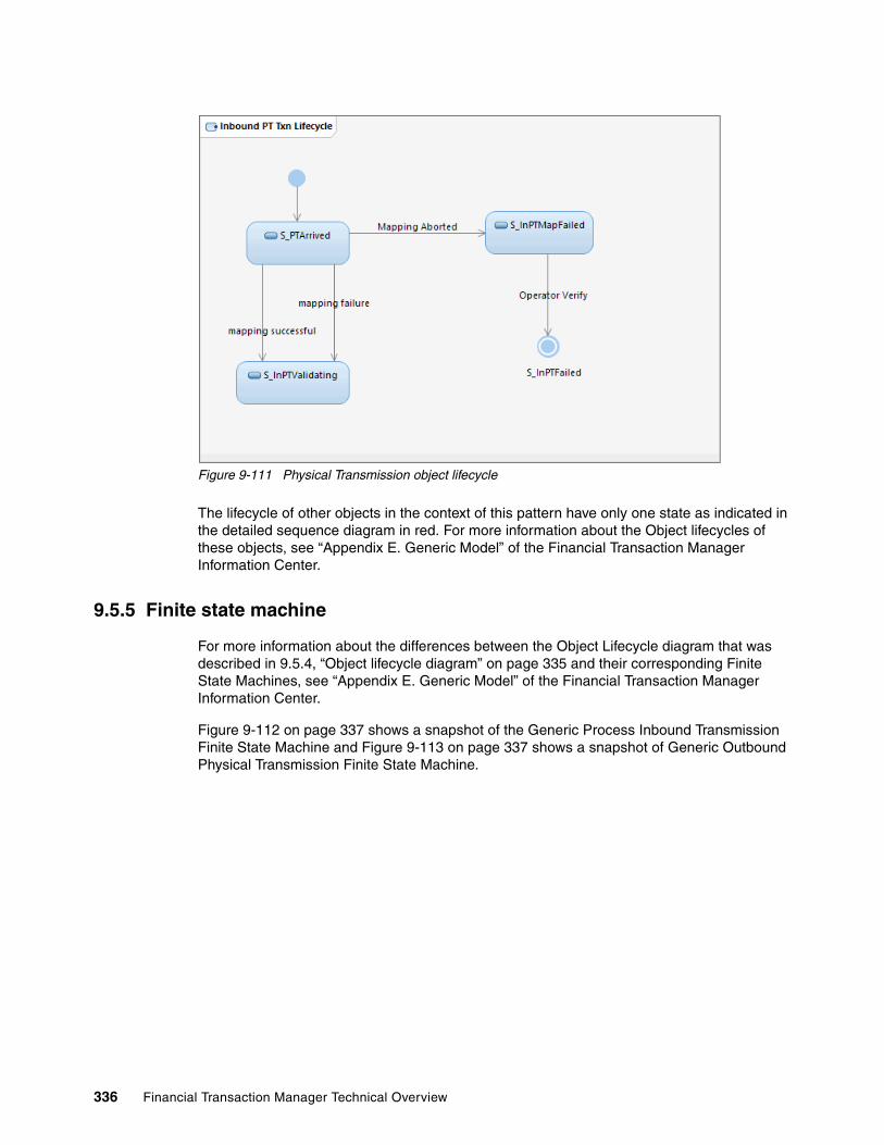
Figure 9-111 Physical Transmission object lifecycle
The lifecycle of other objects in the context of this pattern have only one state as indicated in the detailed sequence diagram in red. For more information about the Object lifecycles of these objects, see “Appendix E. Generic Model” of the Financial Transaction Manager Information Center.
9.5.5 Finite state machine
For more information about the differences between the Object Lifecycle diagram that was described in 9.5.4, “Object lifecycle diagram” on page 335 and their corresponding Finite State Machines, see “Appendix E. Generic Model” of the Financial Transaction Manager Information Center.
Figure 9-112 on page 337 shows a snapshot of the Generic Process Inbound Transmission Finite State Machine and Figure 9-113 on page 337 shows a snapshot of Generic Outbound Physical Transmission Finite State Machine.
336 Financial Transaction Manager Technical Overview

Figure 9-112 Process inbound transmission Finite State Machine snapshot
Figure 9-113 Outbound physical transmission Finite State Machine snapshot
Chapter 9. Patterns 337

9.5.6 Process highlights
This pattern assumes and encourages the use of a generic Finite State Machine that is provided as part of Financial Transaction Manager. The Finite State Machine should cater to most of the inbound and outbound transformation Finite State Machine requirements. If this is not the case and the requirements mandate that a custom Finite State Machine is created for inbound and outbound transformation process, the states and events that are raised by the Financial Transaction Manager core framework do not change. Therefore, a custom Finite State Machine must be modeled with the same state and event names that are mentioned in the generic Finite State Machine. The detailed sequence diagrams that are provided in 9.5.5, “Finite state machine” on page 336 indicate the name of the states that Finite State Machine uses. The following events are raised by Financial Transaction Manager core framework in the context of this pattern:
� E_MpInTxnMapped: When inbound transaction mapping is successful.
� E_MpInTxnMapFailure: When the inbound mapper reports transaction mapping status as Failure.
� E_MpInBatMapped: When inbound batch is successfully mapped.
� E_MpInBatMapFailure: When the inbound mapper reports batch mapping status as Failure.
� E_MpInFragBatMapped: When the inbound fragment is successfully mapped.
� E_MpInMappingAborted: When the inbound mapper reports transaction mapping status as Aborted.
� E_TxnOutCreated: When outbound transaction is created and is ready to be mapped to outbound physical transmission.
9.5.7 Pattern interaction
This pattern can be used with the pattern that is described in 9.1, “Creation of outbound message or file pattern” on page 238 for sending outbound physical transmissions.
For more information about the use of this pattern, see the Financial Transaction Manager Information Center by clicking Appendixes Appendix E. Generic Model Scenario Descriptions Process Inbound Transmission.
9.6 Debulking pattern
Debulking refers to breaking down batch messages into individual transactions, which can then be processed independently through Finite State Machine orchestration.
In Financial Transaction Manager, debulking occurs during Inbound Mapping in which mappers parse the input message that identifies batch and transaction-level message elements. For each of these messages, relevant batch and transaction objects are persisted to the Financial Transaction Manager database.
Figure 9-114 on page 339 shows the basic Use Case for this pattern. It also shows the Batch message that is parsed and mapped into Batch Objects, the processing of which is handled by Batch level Finite State Machines. Also shown are Transaction Objects that each contain an ISF message, the processing of which is handled by Transaction Finite State Machines.
338 Financial Transaction Manager Technical Overview

Figure 9-114 Debulking Pattern Use Case
9.6.1 High-level description
Figure 9-115 on page 340 shows the High-Level Sequence diagram for the Debulking pattern. Financial Transaction Manager receives an inbound batch message, creates an inbound Physical Transmission record in the Financial Transaction Manager database, and then calls an inbound mapper that is based on channel data. The inbound mapper parses the message into batch and transaction objects, and these objects are written to the Financial Transaction Manager database as Batch and Transaction records.
Chapter 9. Patterns 339

Figure 9-115 Debulking pattern High-Level Sequence diagram
9.6.2 Objects and object relationships
The Financial Transaction Manager Objects that are used in this pattern are objects that are logical representations of message elements in the physical message (for example, a Transmission Object can be broken down into Batch and Transaction Objects), or a Fragment Object, which is different in that it is an object that exists in the Financial Transaction Manager datamodel to streamline processing (for example, Fragments are a Financial Transaction Manager concept rather than a concept from the message).
Figure 9-116 shows the relationship between the objects in this pattern.
Figure 9-116 Debulking object and object relationship
340 Financial Transaction Manager Technical Overview

9.6.3 Detailed Sequence diagram
The primary Detailed Sequence diagram that describes this pattern is the Log and Map Batch Detailed Sequence diagram from “Appendix E. Generic Model” in the Financial Transaction Manager 2.1 Information Center.
Figure 9-117 shows the Log and Map Batch Detailed Sequence diagram, which shows the interactions between the Financial Transaction Manager objects and key components.
Figure 9-117 Log and Map Batch Detailed Sequence diagram
For large inbound messages that contain large batches (for example, when the transaction count approaches the 100,000 mark), the inbound message can be split into fragments, which map to Fragment objects in the Financial Transaction Manager database.
Figure 9-118 on page 342 shows the Log and Map Fragmented PT Detailed Sequence diagram as described in “Appendix E. Generic Model” of the Financial Transaction Manager 2.1 Information Center.
Chapter 9. Patterns 341

Figure 9-118 Log and Map Fragmented PT Detailed Sequence diagram
9.6.4 Object Lifecycle diagram
The Object Lifecycles diagrams for this pattern are simple. Each object (Transmission, Batch, and Transaction) goes from an Arrived or Mapped starting state to a Validating state after the Inbound Message is parsed and corresponding events are raised.
Figure 9-119 shows the Object Lifecycle for Inbound Physical Transmission Object.
Figure 9-119 Inbound Debulking PT Lifecycle
342 Financial Transaction Manager Technical Overview

Figure 9-120 shows a typical Object Lifecycle for an Inbound Batch Object. In this example, the Check txn validation counters keeps a count of the number of transactions that passed or failed validation when the batch txn pass or batch txn fail events are triggered. Then, for these two events and the batch mapped event, it checks the sum of these numbers against the total number of transactions for the batch, which are calculated and stored in the database during mapping. If equal, it transitions the batch to the next state by raising the batch txn validation complete event.
Figure 9-120 Inbound Debulking Batch Lifecycle
Figure 9-121 shows a typical Object Lifecycle for an Inbound Transaction Object.
Figure 9-121 Inbound Debulking Txn Lifecycle
Chapter 9. Patterns 343
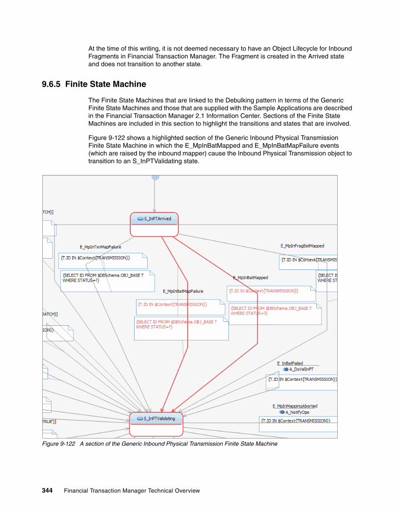
At the time of this writing, it is not deemed necessary to have an Object Lifecycle for Inbound Fragments in Financial Transaction Manager. The Fragment is created in the Arrived state and does not transition to another state.
9.6.5 Finite State Machine
The Finite State Machines that are linked to the Debulking pattern in terms of the Generic Finite State Machines and those that are supplied with the Sample Applications are described in the Financial Transaction Manager 2.1 Information Center. Sections of the Finite State Machines are included in this section to highlight the transitions and states that are involved.
Figure 9-122 shows a highlighted section of the Generic Inbound Physical Transmission Finite State Machine in which the E_MpInBatMapped and E_MpInBatMapFailure events (which are raised by the inbound mapper) cause the Inbound Physical Transmission object to transition to an S_InPTValidating state.
Figure 9-122 A section of the Generic Inbound Physical Transmission Finite State Machine
344 Financial Transaction Manager Technical Overview
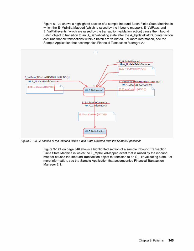
Figure 9-123 shows a highlighted section of a sample Inbound Batch Finite State Machine in which the E_MpInBatMapped (which is raised by the inbound mapper), E_ValPass, and E_ValFail events (which are raised by the transaction validation action) cause the Inbound Batch object to transition to an S_BatValidating state after the A_UpdateBatchCounter action confirms that all transactions within a batch are validated. For more information, see the Sample Application that accompanies Financial Transaction Manager 2.1.
Figure 9-123 A section of the Inbound Batch Finite State Machine from the Sample Application
Figure 9-124 on page 346 shows a highlighted section of a sample Inbound Transaction Finite State Machine in which the E_MpInTxnMapped event that is raised by the inbound mapper causes the Inbound Transaction object to transition to an S_TxnValidating state. For more information, see the Sample Application that accompanies Financial Transaction Manager 2.1.
Chapter 9. Patterns 345
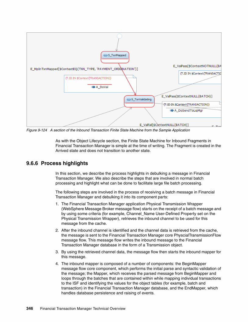
Figure 9-124 A section of the Inbound Transaction Finite State Machine from the Sample Application
As with the Object Lifecycle section, the Finite State Machine for Inbound Fragments in Financial Transaction Manager is simple at the time of writing. The Fragment is created in the Arrived state and does not transition to another state.
9.6.6 Process highlights
In this section, we describe the process highlights in debulking a message in Financial Transaction Manager. We also describe the steps that are involved in normal batch processing and highlight what can be done to facilitate large file batch processing.
The following steps are involved in the process of receiving a batch message in Financial Transaction Manager and debulking it into its component parts:
1. The Financial Transaction Manager application Physical Transmission Wrapper (WebSphere Message Broker message flow) starts on the receipt of a batch message and by using some criteria (for example, Channel_Name User-Defined Property set on the Physical Transmission Wrapper), retrieves the inbound channel to be used for this message from the cache.
2. After the inbound channel is identified and the channel data is retrieved from the cache, the message is sent to the Financial Transaction Manager core PhyscialTransmissionFlow message flow. This message flow writes the inbound message to the Financial Transaction Manager database in the form of a Transmission object.
3. By using the retrieved channel data, the message flow then starts the inbound mapper for this message.
4. The inbound mapper is composed of a number of components: the BeginMapper message flow core component, which performs the initial parse and syntactic validation of the message; the Mapper, which receives the parsed message from BeginMapper and loops through the batches that are contained within while mapping individual transactions to the ISF and identifying the values for the object tables (for example, batch and transaction) in the Financial Transaction Manager database, and the EndMapper, which handles database persistence and raising of events.
346 Financial Transaction Manager Technical Overview
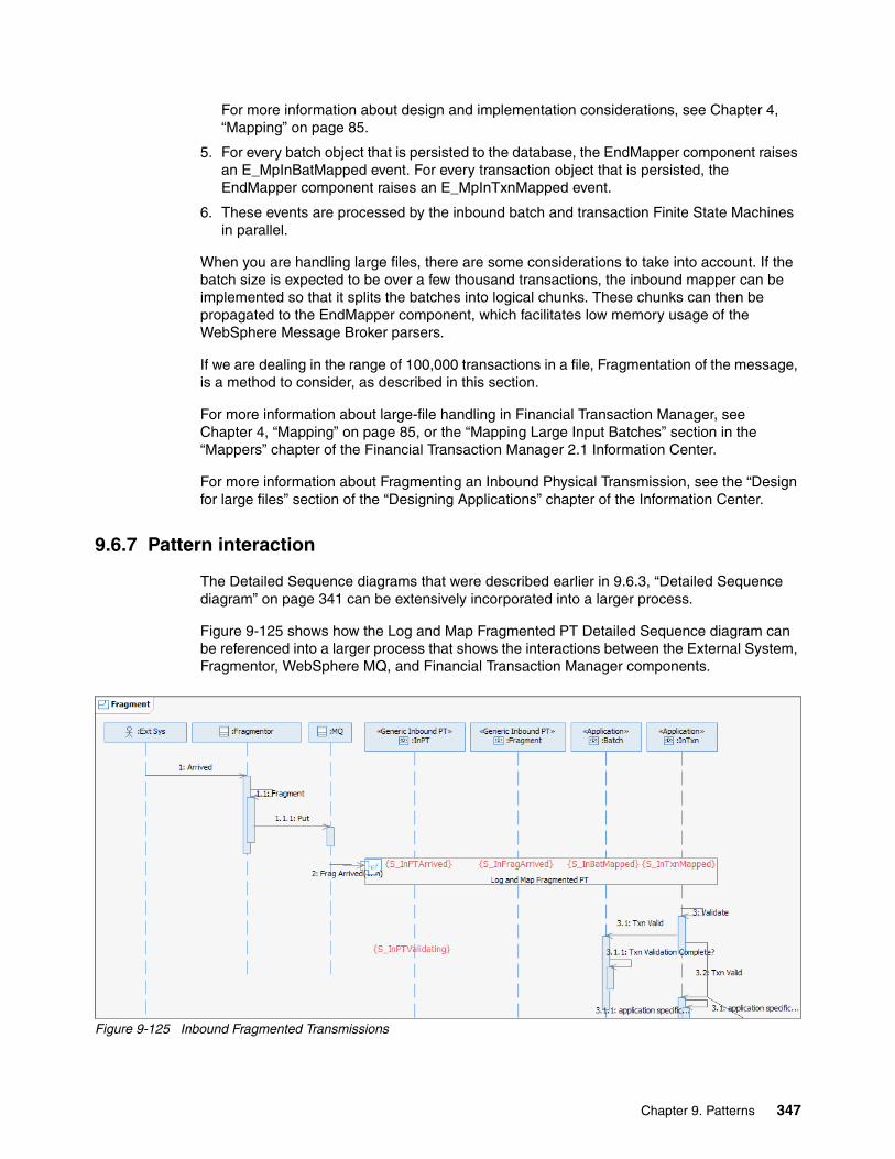
For more information about design and implementation considerations, see Chapter 4, “Mapping” on page 85.
5. For every batch object that is persisted to the database, the EndMapper component raises an E_MpInBatMapped event. For every transaction object that is persisted, the EndMapper component raises an E_MpInTxnMapped event.
6. These events are processed by the inbound batch and transaction Finite State Machines in parallel.
When you are handling large files, there are some considerations to take into account. If the batch size is expected to be over a few thousand transactions, the inbound mapper can be implemented so that it splits the batches into logical chunks. These chunks can then be propagated to the EndMapper component, which facilitates low memory usage of the WebSphere Message Broker parsers.
If we are dealing in the range of 100,000 transactions in a file, Fragmentation of the message, is a method to consider, as described in this section.
For more information about large-file handling in Financial Transaction Manager, see Chapter 4, “Mapping” on page 85, or the “Mapping Large Input Batches” section in the “Mappers” chapter of the Financial Transaction Manager 2.1 Information Center.
For more information about Fragmenting an Inbound Physical Transmission, see the “Design for large files” section of the “Designing Applications” chapter of the Information Center.
9.6.7 Pattern interaction
The Detailed Sequence diagrams that were described earlier in 9.6.3, “Detailed Sequence diagram” on page 341 can be extensively incorporated into a larger process.
Figure 9-125 shows how the Log and Map Fragmented PT Detailed Sequence diagram can be referenced into a larger process that shows the interactions between the External System, Fragmentor, WebSphere MQ, and Financial Transaction Manager components.
Figure 9-125 Inbound Fragmented Transmissions
Chapter 9. Patterns 347
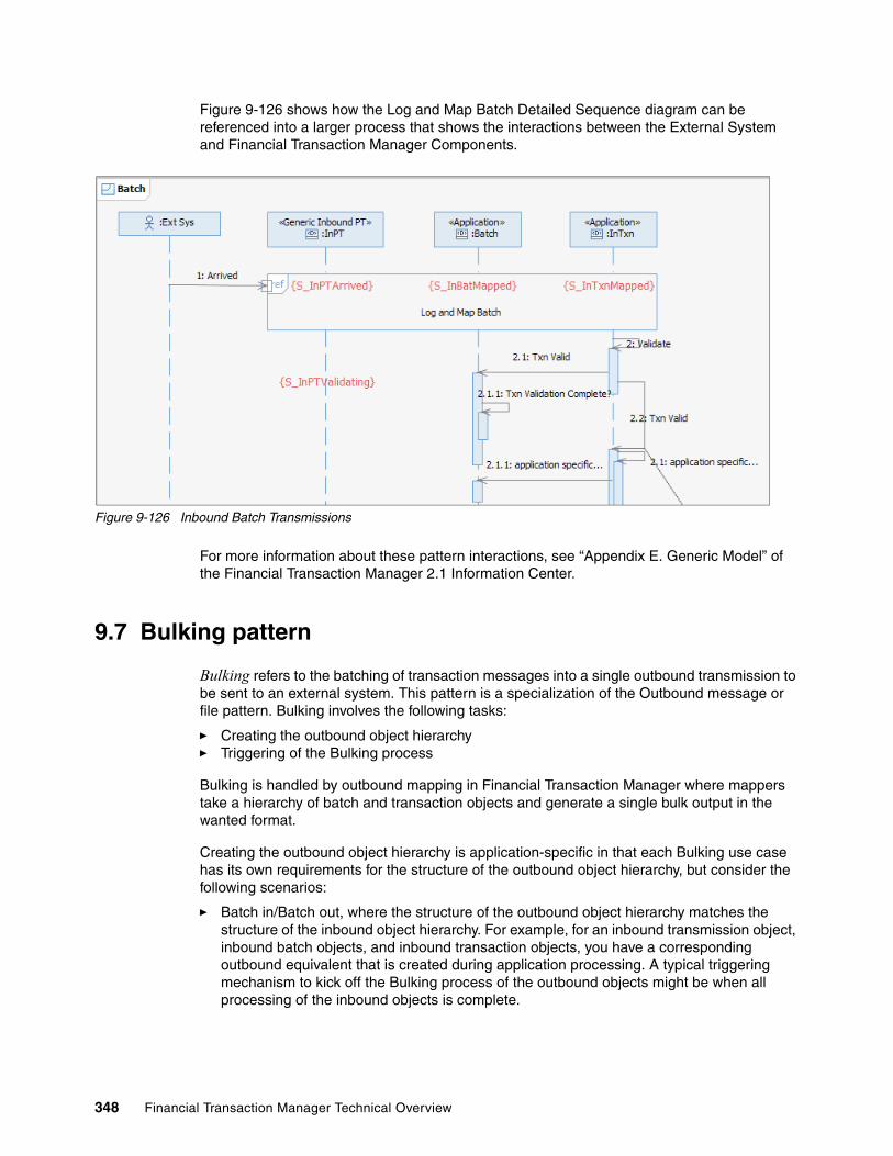
Figure 9-126 shows how the Log and Map Batch Detailed Sequence diagram can be referenced into a larger process that shows the interactions between the External System and Financial Transaction Manager Components.
Figure 9-126 Inbound Batch Transmissions
For more information about these pattern interactions, see “Appendix E. Generic Model” of the Financial Transaction Manager 2.1 Information Center.
9.7 Bulking pattern
Bulking refers to the batching of transaction messages into a single outbound transmission to be sent to an external system. This pattern is a specialization of the Outbound message or file pattern. Bulking involves the following tasks:
� Creating the outbound object hierarchy� Triggering of the Bulking process
Bulking is handled by outbound mapping in Financial Transaction Manager where mappers take a hierarchy of batch and transaction objects and generate a single bulk output in the wanted format.
Creating the outbound object hierarchy is application-specific in that each Bulking use case has its own requirements for the structure of the outbound object hierarchy, but consider the following scenarios:
� Batch in/Batch out, where the structure of the outbound object hierarchy matches the structure of the inbound object hierarchy. For example, for an inbound transmission object, inbound batch objects, and inbound transaction objects, you have a corresponding outbound equivalent that is created during application processing. A typical triggering mechanism to kick off the Bulking process of the outbound objects might be when all processing of the inbound objects is complete.
348 Financial Transaction Manager Technical Overview

� Single in/Batch out, where single inbound transactions are processed and outbound transactions are created as part of this processing. Then, based on a threshold or time trigger, the Bulking process creates the outbound batch object or objects and links the outbound transactions to a batch that is based on the triggering criteria. For example, if the trigger is “End of day,” the selection criteria is all outbound transactions in a certain state with a creation date less than or equal to today.
The following triggers are available:
� A schedule (for example, time of day, end of week, or end of month)� Inbound processing completion (for example, all inbound batches validated)� Threshold reached (for example, 1000 transactions validated)� Operator intervention (for example, the operator signals a Start Bulk action)
Figure 9-127 shows the basic Use Case for this pattern.
Figure 9-127 Bulking pattern use case
9.7.1 High-level description
Figure 9-128 on page 350 shows the High-Level Sequence diagram of a Bulking scenario in which the outbound Physical Transmission, Batch, and Transaction object hierarchy is built, a mechanism is triggered to indicate that the objects are ready for bulking, an event is raised to indicate this readiness, and a batched transmission is sent to an external system. The diagram references a High-Level Sequence diagram that is used in the Outbound Message or File Pattern. Error scenarios for this pattern are also covered in the Outbound Message or File Pattern.
Chapter 9. Patterns 349

Figure 9-128 Bulking pattern High-Level Sequence diagram (Batch)
Figure 9-129 on page 351 shows the High-Level Sequence diagram of a Bulking scenario in which the outbound Physical Transmission, Fragment, Batch, and Transaction object hierarchy is built, a mechanism is triggered to indicate that the objects are ready for bulking, an event is raised to indicate this readiness, and a fragmented transmission is sent to an external system. The diagram references a High-Level Sequence diagram that is used in the Outbound Message or File Pattern. Error scenarios for this pattern are also covered in the Outbound Message or File Pattern.
350 Financial Transaction Manager Technical Overview

Figure 9-129 Bulking pattern High-Level Sequence diagram (Fragment)
9.7.2 Objects and object relationships
Figure 9-130 shows the Financial Transaction Manager Objects and Object relationships that are used for this pattern.
Figure 9-130 Bulking Object/Object Relationship
Chapter 9. Patterns 351
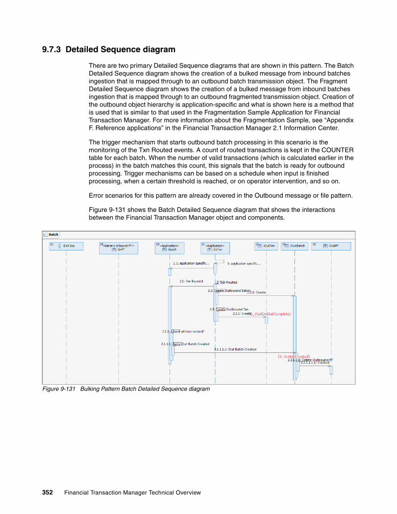
9.7.3 Detailed Sequence diagram
There are two primary Detailed Sequence diagrams that are shown in this pattern. The Batch Detailed Sequence diagram shows the creation of a bulked message from inbound batches ingestion that is mapped through to an outbound batch transmission object. The Fragment Detailed Sequence diagram shows the creation of a bulked message from inbound batches ingestion that is mapped through to an outbound fragmented transmission object. Creation of the outbound object hierarchy is application-specific and what is shown here is a method that is used that is similar to that used in the Fragmentation Sample Application for Financial Transaction Manager. For more information about the Fragmentation Sample, see “Appendix F. Reference applications” in the Financial Transaction Manager 2.1 Information Center.
The trigger mechanism that starts outbound batch processing in this scenario is the monitoring of the Txn Routed events. A count of routed transactions is kept in the COUNTER table for each batch. When the number of valid transactions (which is calculated earlier in the process) in the batch matches this count, this signals that the batch is ready for outbound processing. Trigger mechanisms can be based on a schedule when input is finished processing, when a certain threshold is reached, or on operator intervention, and so on.
Error scenarios for this pattern are already covered in the Outbound message or file pattern.
Figure 9-131 shows the Batch Detailed Sequence diagram that shows the interactions between the Financial Transaction Manager object and components.
Figure 9-131 Bulking Pattern Batch Detailed Sequence diagram
352 Financial Transaction Manager Technical Overview

Figure 9-132 shows the Fragment Detailed Sequence diagram that shows the interactions between the Financial Transaction Manager object and components.
Figure 9-132 Bulking Pattern Fragment Detailed Sequence diagram
9.7.4 Object lifecycle diagram
The Object lifecycle diagrams for this pattern are largely based on what is modeled in the Finite State Machines for Outbound Fragments and Outbound Transactions in the Financial Transaction Manager Generic Model. The Object lifecycle for Outbound Batches is largely application-specific. The Outbound Physical Transmission Object lifecycle is described in 9.1, “Creation of outbound message or file pattern” on page 238.
For the Batch Object lifecycle, an approach that is similar to that used in the Fragmentation Sample Application is shown as a guide.
Chapter 9. Patterns 353

Figure 9-133 shows the object lifecycle for an Outbound Fragment Object. For more information, see Appendix E. Generic Model of the Financial Transaction Manager 2.1 Information Center.
Figure 9-133 Outbound Fragment Lifecycle
354 Financial Transaction Manager Technical Overview

Figure 9-134 shows a possible object lifecycle for an Outbound Batch Object. The Outbound Batch object is created in the S_OutBatchCreated state. When all transactions for the batch are ready to be processed, an “outbound batch Created” event is raised to signal the creation of an Outbound Physical Transmission (or Fragment). After the Outbound Physical Transmission is processed, an Outbound PT Sent event is transitioned to complete outbound batch processing process.
Figure 9-134 Outbound Batch Lifecycle
Figure 9-135 on page 356 shows the object lifecycle for an Outbound Transaction Object. The Outbound Transaction object is created in the S_WaitOutBatComplete state. When the outbound batch is processed, the outbound batch orchestration can raise “outbound batch txn complete” events to signal that the Outbound Transactions can move to a complete state, or in the case of a batch failure, an “outbound batch failed” event is raised and the Outbound Transactions moves to a failed state.
Chapter 9. Patterns 355

Figure 9-135 Outbound Transaction Lifecycle
9.7.5 Finite State Machine
For more information about the Generic Outbound Fragment and Outbound Transaction Finite State Machines that are used by this pattern, see “Appendix E. Generic Model” in the Financial Transaction Manager 2.1 Information Center.
The Finite State Machines for the Outbound Batch Object as described in 9.7.4, “Object lifecycle diagram” on page 353, is straightforward and is described in “Appendix F. Reference Applications” section of the Financial Transaction Manager 2.1 Information Center.
Processing of the Outbound Batches is application-specific; therefore, no Generic Outbound Batch Finite State Machines are available to handle the orchestration of these objects for the Bulking pattern.
9.7.6 Process highlights
The Bulking pattern is a specialization of the Outbound Message or File pattern. The Bulking pattern includes the following main tasks:
� Creating the outbound object hierarchy� Triggering the outbound orchestration
After these tasks are complete, the Outbound Message or File pattern takes over to handle the process of passing the outbound physical transmission to an endpoint.
Creating the outbound object hierarchy is largely application-specific. Application design highlights the object relationships from inbound to outbound and, depending on the use case requirements, a set of outbound transaction objects of a certain subtype are created in the Financial Transaction Manager database, which is linked by a foreign key to a set of outbound batch objects of a certain subtype that also are created in the database. These outbound batch objects can be linked to an outbound fragment object or objects (depending on size) and are linked to an outbound physical transmission object through a foreign key relationship.
356 Financial Transaction Manager Technical Overview

Careful thought must be applied to the triggering mechanism for the outbound bulking process. The process is started by the E_PTOutCreated event (if the Generic Outbound Physical Transmission is used) and the raising of this event, which is coupled with the correct Event Context data, starts the processing of the outbound physical message. It is important to ensure that all outbound batches and transactions that are related to this outbound physical transmission are in the correct state for sending (whatever state that is) and that the process that is controlling the triggering mechanism must cater for this.
If the trigger is based on a schedule, the Scheduler Task object tables should be used to support this configuration. For more information, see the Scheduled Activity and Scheduled Expectation patterns that are decribed in 9.12, “Scheduled activity pattern” on page 415 and 9.13, “Scheduled expectation pattern” on page 423.
If the trigger is based on the completion of inbound or outbound processing or based on some threshold being reached, the COUNTER table can be used to track the number of a particular transaction event that is raised against transactions in a batch (by using the TRANSACTION event context). This can be checked against a count of the number of transactions in a batch, as used in the Fragmentation Sample Application.
9.7.7 Pattern interaction
This pattern interacts with the Outbound Message or File pattern, which handles the actual propagation of physical outbound message. As part of a larger process, it can be coupled with many of the other patterns to produce an end-to-end design for a solution. For example, the Debulking pattern with Transformation, Semantic Validation, and Enrichment patterns all can be coupled with some application-specific orchestration, and the Scheduled Activity or Scheduled Expectation pattern and this Bulking pattern to describe a complete object lifecycle process.
Chapter 9. Patterns 357

Figure 9-136 shows an example of these interactions, which combine the Debulking, Bulking, and Outbound Message or File Patterns.
Figure 9-136 Pattern Interactions
9.8 Store and release pattern
It is common for applications to create forward-dated transactions that should be stored in a transaction warehouse until they are released on a certain date and time. In addition, a number of clearing and settlement mechanisms allow only the transmission of messages to them in a specific time window during a working day; transactions must be stored until this window opens.
Financial Transaction Manager can perform this task by using routing and scheduler objects that allow the date information of a transaction (for example, a payment’s value date) to define the release date for the transaction and then transition them to an Awaiting Release state at the appropriate date or time.
358 Financial Transaction Manager Technical Overview
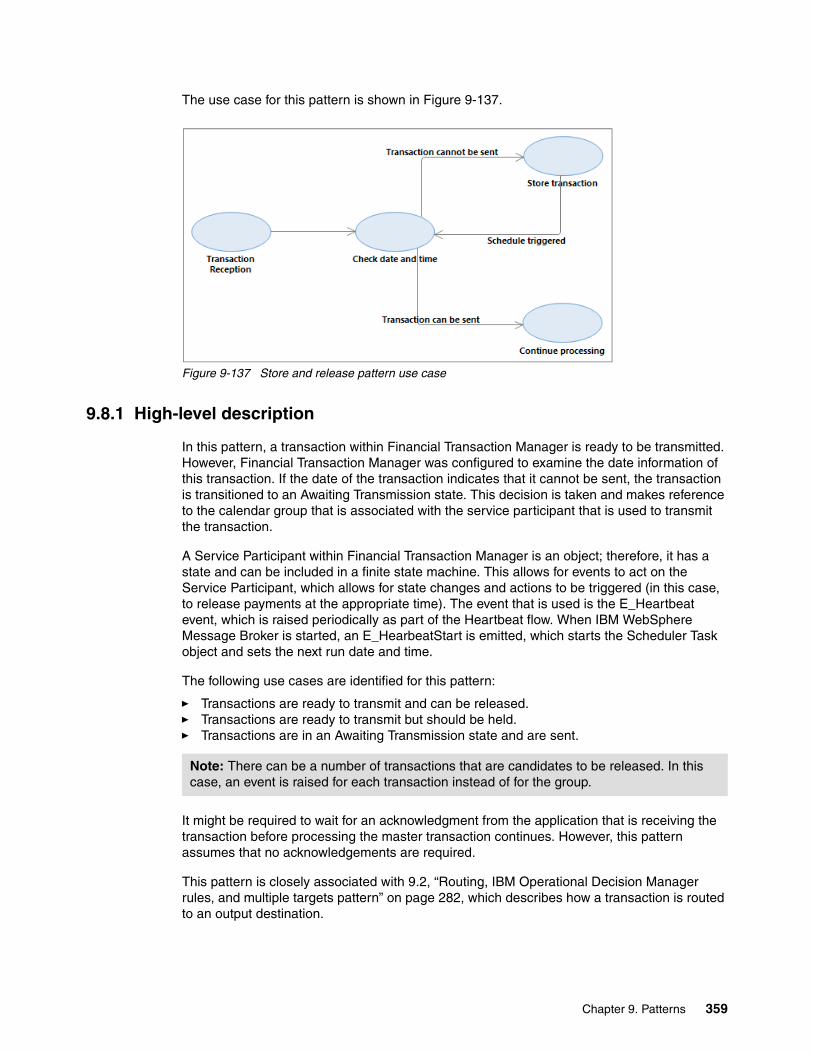
The use case for this pattern is shown in Figure 9-137.
Figure 9-137 Store and release pattern use case
9.8.1 High-level description
In this pattern, a transaction within Financial Transaction Manager is ready to be transmitted. However, Financial Transaction Manager was configured to examine the date information of this transaction. If the date of the transaction indicates that it cannot be sent, the transaction is transitioned to an Awaiting Transmission state. This decision is taken and makes reference to the calendar group that is associated with the service participant that is used to transmit the transaction.
A Service Participant within Financial Transaction Manager is an object; therefore, it has a state and can be included in a finite state machine. This allows for events to act on the Service Participant, which allows for state changes and actions to be triggered (in this case, to release payments at the appropriate time). The event that is used is the E_Heartbeat event, which is raised periodically as part of the Heartbeat flow. When IBM WebSphere Message Broker is started, an E_HearbeatStart is emitted, which starts the Scheduler Task object and sets the next run date and time.
The following use cases are identified for this pattern:
� Transactions are ready to transmit and can be released.� Transactions are ready to transmit but should be held.� Transactions are in an Awaiting Transmission state and are sent.
It might be required to wait for an acknowledgment from the application that is receiving the transaction before processing the master transaction continues. However, this pattern assumes that no acknowledgements are required.
This pattern is closely associated with 9.2, “Routing, IBM Operational Decision Manager rules, and multiple targets pattern” on page 282, which describes how a transaction is routed to an output destination.
Note: There can be a number of transactions that are candidates to be released. In this case, an event is raised for each transaction instead of for the group.
Chapter 9. Patterns 359
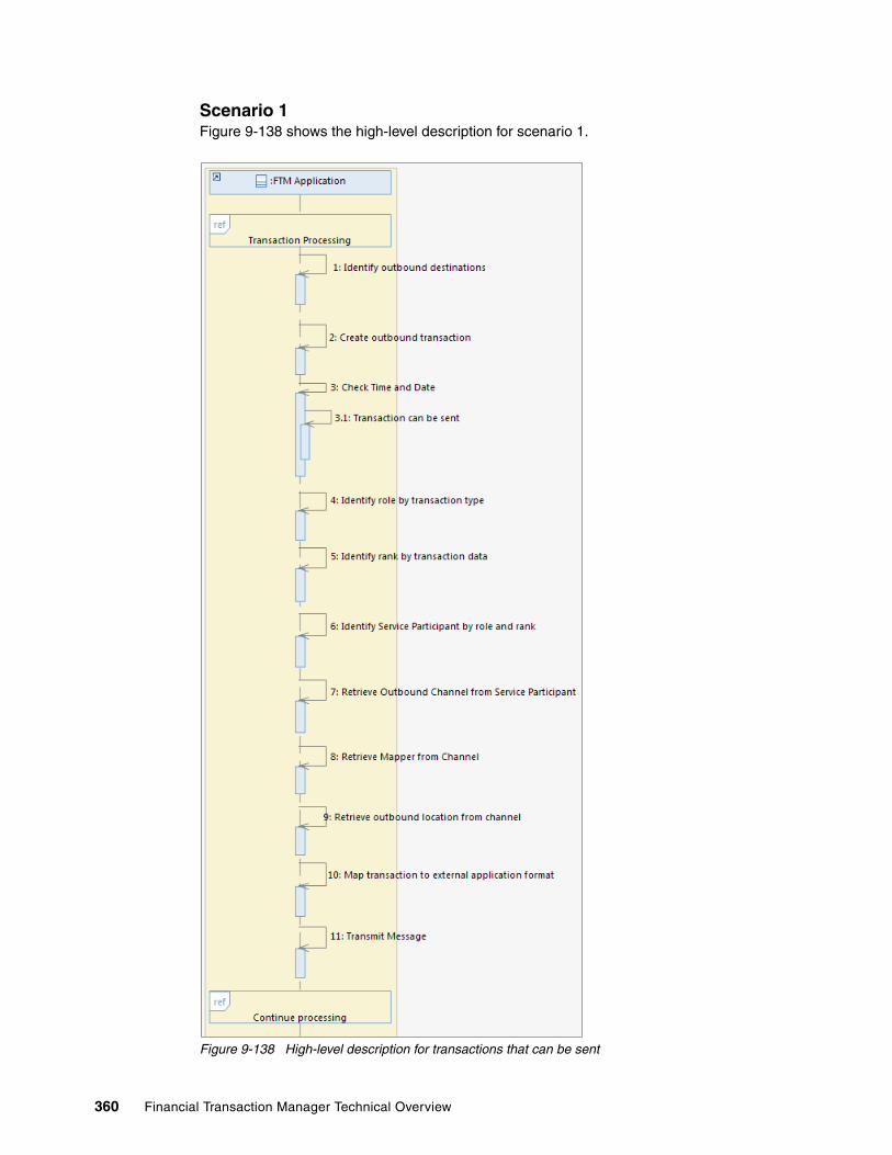
Scenario 1Figure 9-138 shows the high-level description for scenario 1.
Figure 9-138 High-level description for transactions that can be sent
360 Financial Transaction Manager Technical Overview

In this scenario, the following process occurs:
1. A transaction is received and processed.
2. A destination is identified and an outbound transaction is created.
3. The Scheduler Task is prompted by the Heartbeat event and starts an action, which identifies the transactions that can be released.
4. An appropriate event is raised for each transaction as defined within a Finite State Machine, which causes a state change and an action to be performed.
5. The transaction is sent, as described in 9.2, “Routing, IBM Operational Decision Manager rules, and multiple targets pattern” on page 282.
Scenario 2Figure 9-139 shows the high-level description for transactions that are held.
Figure 9-139 High-level description for transactions that cannot be sent
In this scenario, the following process occurs:
1. A transaction is received and is processed.
2. A destination is identified and an outbound transaction is created and stored in a state of Awaiting Release.
3. The Heartbeat Event causes the Scheduler Task’s finite state machine to start an action that attempts to identify all transactions (which can be transmitted) that is based on their release date and time.
The outgoing transaction’s date information is outside the sending timescale and is not identified as a transaction, which can be transmitted.
4. The outgoing transaction stays in an Awaiting Release state.
5. The original master transaction continues to be processed.
Chapter 9. Patterns 361

Scenario 3The third scenario describes the release of the outgoing transaction from the Awaiting Release state and is shown in Figure 9-140.
Figure 9-140 High-level description for transmitting held transactions
362 Financial Transaction Manager Technical Overview

In this scenario, the following process occurs:
1. Outgoing transactions are held in an Awaiting Release state.
2. The Scheduler Task is triggered by an E_Heartbeat event and performs an action.
3. The Scheduler’s Task change in transition starts an action.
4. The action runs and retrieves a list of transactions that are associated with it that can be released.
5. For each transaction that is retrieved, the action raises a release event against it, which causes the transaction to be processed and transmitted.
9.8.2 Objects and object relationships
This pattern consists of the following objects:
� Master transaction� Outbound transaction� Scheduler Task
The object relationship diagram is shown in Figure 9-141.
Figure 9-141 Object Relationship diagram for Store and Release
9.8.3 Detailed sequence diagram
The detailed sequence diagram for this pattern shows the interactions between the Financial Transaction Manager objects.
In this pattern, the following use cases are identified:
� A transaction is to be transmitted and is allowed.� A transaction is to be transmitted but is not allowed.� A transaction is in an Awaiting Release state and is released by the Scheduler Task.
Chapter 9. Patterns 363

Scenario 1The detailed sequence diagram for the first scenario is shown in Figure 9-142. In this scenario, a transaction’s due date is compared to the release rules that were created, the date is found to be valid, and the transaction is transmitted.
Figure 9-142 Detailed Sequence Diagram: Transaction sent without hold
364 Financial Transaction Manager Technical Overview

Scenario 2In the second scenario, a transaction is to be sent, its due date is compared to the release rules that were defined, found to be invalid, and the transaction is moved to a state of Awaiting Release. The detailed sequence diagram is shown in Figure 9-143.
Figure 9-143 Detailed Sequence Diagram: Transaction Held
Scenario 3In the third scenario, transactions are in an Awaiting Release state and the Scheduler Task is triggered by a heartbeat event, E_Heartbeat. The Scheduler Task creates a list of the transactions that are to be released and then raises a release event against each transaction. The transaction is then transmitted, as shown in Figure 9-144.
Figure 9-144 Detailed Sequence Diagram: Transaction Release
Chapter 9. Patterns 365

9.8.4 Object lifecycle diagram
This pattern includes the following objects:
� Master transaction� Outbound transaction� Scheduler task
In this pattern, the Scheduler Task lifecycle consists of one state and the master transaction’s lifecycle are out of scope, so it is are not covered in this section. The lifecycle of the outgoing transaction is shown in Figure 9-145.
Figure 9-145 Object lifecycle diagram for outgoing transaction
9.8.5 Finite State Machine
In this pattern, there are two main Finite State Machines that are used, which does not include the Heartbeat finite state machine that is described in 9.14, “Heartbeats monitoring (scheduling) pattern” on page 431. The following Finite State Machines are available:
� Finite State Machine for the outbound transaction� Finite State Machine for the Scheduler Task.
The Scheduler Task is a Financial Transaction Manager object and includes an associated state. By using this configuration, it can be included within Finite State Machines, be affected by events, and have actions run.
An example of a Finite State Machine for a Scheduler Task object is shown in Figure 9-146 on page 367.
366 Financial Transaction Manager Technical Overview

Figure 9-146 Finite State Machine for Scheduler Task
The Finite State Machine for the Scheduler Task object is straightforward; the service is started by the E_HeartbeatStart when WebSphere Message Broker starts. The A_initTransactionRelease action sets up several variables that are used while the service is active; for example, the next run date and time.
The actual service is triggered by the E_Heartbeat event, which causes the A_ReleaseHeldTransactions action to be run at the appropriate time.
This Finite State Machine triggers only the Payment Release service, as shown in the master object selector panel in Figure 9-147.
Figure 9-147 Master Object Selector panel for Payment Release Service Finite State Machine
The Finite State Machine for the outgoing transaction is shown in Figure 9-148 on page 368.
Chapter 9. Patterns 367

Figure 9-148 Finite State Machine for Outgoing Transaction
In this Finite State Machine, the following process occurs:
1. The outgoing transaction is created with an initial state of OutTxnCreated.
2. The E_CheckSchedule event is raised and the transaction is moved to a state of S_CheckingDate.
3. At the same time, the A_SendToApp action is started, which checks the due date of the transaction and raises the appropriate event.
If the transaction’s due date falls outside of the transmission window, the transaction is moved to the S_AwaitingRelease state.
If the transaction can be sent, the process continues and the transaction is sent.
4. When the Scheduler Task is triggered, it obtains a list of transactions that it can release and raises a E_ScheduleTriggered event for each of them.
5. The held transaction is released and processed by the A_ReleaseTransaction action.
6. The transaction is transmitted.
9.8.6 Process highlights
This store and release of transactions is achieved within Financial Transaction Manager by the creation and configuration of several objects. They can be created within the Operations and Administration Console, as described in Chapter 6, “User interface” on page 153, or within Rational Software Architect as part of the model.
368 Financial Transaction Manager Technical Overview

The detail of the objects and processes that are expected with Scheduled Activities is described in 9.12, “Scheduled activity pattern” on page 415.
The Scheduler Task object is defined in Rational Software Architect, as shown in Figure 9-149.
Figure 9-149 Definition of Service Participant in Rational Software Architect
The definition of a Scheduler Task allows for a basic schedule to be defined (for example, a task time) a link to an associated calendar, and so forth.
A Calendar Group object is defined within Rational Software Architect, as shown in Figure 9-150.
Figure 9-150 Definition of a Calendar Group in Rational Software Architect
Chapter 9. Patterns 369
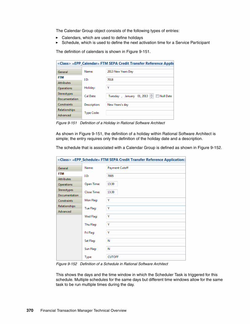
The Calendar Group object consists of the following types of entries:
� Calendars, which are used to define holidays� Schedule, which is used to define the next activation time for a Service Participant
The definition of calendars is shown in Figure 9-151.
Figure 9-151 Definition of a Holiday in Rational Software Architect
As shown in Figure 9-151, the definition of a holiday within Rational Software Architect is simple; the entry requires only the definition of the holiday date and a description.
The schedule that is associated with a Calendar Group is defined as shown in Figure 9-152.
Figure 9-152 Definition of a Schedule in Rational Software Architect
This shows the days and the time window in which the Scheduler Task is triggered for this schedule. Multiple schedules for the same days but different time windows allow for the same task to be run multiple times during the day.
370 Financial Transaction Manager Technical Overview

When WebSphere Message Broker starts, a E_HeartbeatStart is issued that causes an action to be triggered to start the Scheduler Task. This action examines the Calendar Group that is associated with the Scheduler Task and calculates the next date and time it should be triggered. This value is stored with the Scheduler Task in the TIMEOUT field within the Financial Transaction Manager database.
When the E_Heartbeat is issued (every 60 seconds by default), the Finite State Machine that is associated with the Scheduler Task checks the TIMEOUT that is associated and if the date and time that are held within the field was reached, the action that is associated with the event is triggered. This is achieved with the Finite State Machine for the Scheduler Task by using the $Context{NOW{ >= TIMEOUT object filter, as shown in Figure 9-146 on page 367.
This action then examines the transactions that are held in the Financial Transaction Manager database in a S_AwaitingRelease state that is based on the selection criteria that is defined within the action. The Service Participant then raises an E_ScheduleTriggered against each of the transactions that are within the list.
9.8.7 Pattern interaction
This pattern interacts with the other scheduling patterns that are described in the following sections:
� 9.12, “Scheduled activity pattern” on page 415� 9.13, “Scheduled expectation pattern” on page 423� 9.14, “Heartbeats monitoring (scheduling) pattern” on page 431
This pattern is also closely linked to identifying destinations for transactions, which is described in 9.2, “Routing, IBM Operational Decision Manager rules, and multiple targets pattern” on page 282.
Chapter 9. Patterns 371

9.9 Starting external services pattern
This pattern describes how Financial Transaction Manager can start a service that is hosted by an external system. The service that is shown by the external system can be synchronous or asynchronous in nature. Figure 9-153 shows a high-level use case for a business transaction to make an external service invocation.
Figure 9-153 High-level use case diagram of external service invocation
9.9.1 High-level description
Starting an asynchronous external service, involves calling it from an action within the Finite State Machine processing of the business transaction.
Starting an asynchronous external service includes the following tasks:
� Sending the outbound transaction that corresponds to the request.
� Processing the incoming response and then correlating it to the outbound transaction. Then, flagging the business transaction of the completion of the request.
The action processing for the business transaction creates the request transaction object for the outbound external service. The processing then starts the request transaction object with the ISF that corresponds to the invocation.
Financial Transaction Manager then processes the transaction by using the Generic Outbound Transaction Finite State Machine.
After appropriately determining the routing, this processing calls the OutboundMapper to convert the request ISF to the external service format. The processing then sends the transmission to the external system. From then on, it creates and logs the request transmission object for the outgoing transaction.
The external system then processes the received message and sends back the response asynchronously.
372 Financial Transaction Manager Technical Overview

Financial Transaction Manager then receives the transmission and (after mapping and creating the necessary response transmission and transaction objects) allows Generic Acknowledgement Transaction Finite State Machine to process the response.
After the chosen correlation strategy is used, this processing correlates to the request transaction and raises appropriate events.
Based on these events, the request transaction that was created earlier completes its processing and raises further events. These raised events indicate the request completion for the business transaction to continue.
In this section, we describe the high-level interaction between Financial Transaction Manager and the external service for starting an external service. We describe the positive flow and the following alternative scenarios:
� Response mapping that is aborted� Response not arriving from the external system� Response failed to correlate to the request
Figure 9-154 shows a high-level sequence diagram for sending the outbound transmission that corresponds to the request to the external system.
Figure 9-154 Sending of request to the external system
The following details are shown in Figure 9-154:
1. The Financial Transaction Manager application is processing a business message in a business transaction. As part of the action handling, it wants to make an asynchronous invocation to an external service.
2. Financial Transaction Manager first creates an ISF that represents the external service invocation request from the business transaction ISF and (optionally) enriches it.
3. It creates the request transaction that corresponds to the external service request and raises an event to indicate the Out Transaction Creation.
Chapter 9. Patterns 373

4. The Generic Outbound Transaction Finite State Machine then takes over processing the out transaction, as described in 9.1, “Creation of outbound message or file pattern” on page 238.
For more information about sending the outbound transaction that corresponds to the request, see 9.1, “Creation of outbound message or file pattern” on page 238.
In the remainder of this section, we describe processing the incoming response.
Figure 9-155 shows a sequence diagram for the successful processing of the response from the external system.
Figure 9-155 Successful receipt of the response processing
The following process is shown in Figure 9-155:
1. The external system sends the response to Financial Transaction Manager by using any of the protocols that are supported by WebSphere Message Broker, such as WebSphere MQ and JMS.
374 Financial Transaction Manager Technical Overview
2. Financial Transaction Manager processes the incoming response by using the physical transmission flow and, after logging the incoming response transmission, maps the incoming format to ISF. On successful mapping, Financial Transaction Manager raises the mapping successful event. For more information about mapping, see 9.5, “Transformation pattern” on page 318.
3. The response transaction (as it is associated with the response and the mapped ISF) is also logged.
4. The Generic Acknowledgement Transaction Finite State Machine (which processes the response transaction) correlates to the request transaction by using the appropriate chosen correlation strategies.
For more information about the various correlation strategies, see the Financial Transaction Manager 2.1 Information Center by clicking Application Programming External Service Interaction.
5. On successful correlation, the relationship between the request and response transactions are updated and the Correlation Successful event is raised.
6. The Generic Outbound Request Transaction Finite State Machine, which processes the original request transaction, raises the Request Completed event. By determining whether any business events are associated with the request transaction’s successful completion, it also raises them.
7. The Business Transaction Finite State Machine processes this business event and progresses accordingly.
For more information about the input and output nodes, see the WebSphere Message Broker 7.0 information center by clicking Reference Message flow development Built-in nodes.
Figure 9-156 on page 376 shows the mapping aborted scenario for the received response.
Chapter 9. Patterns 375

Figure 9-156 Scenario where the response mapping is aborted
The following process is shown in Figure 9-156:
1. The external system sends the response to Financial Transaction Manager by using any of the protocols that are supported by WebSphere Message Broker, such as WebSphere MQ and JMS.
2. The Financial Transaction Manager processes the incoming response by using the physical transmission flow and (after logging the incoming response transmission), tries to map the incoming format to ISF. This step fails, a Mapping Aborted event is raised, and an error is logged. For more information about mapping, see 9.5, “Transformation pattern” on page 318.
3. The Generic Incoming Transmission Finite State Machine, which processes the response transmission, notifies the operator of the failed transaction.
4. The operator cancels the failed transmission by using the Operations and Administrative Console (OAC). The transmission is updated as failed and the Failed Transmission event is raised.
5. The Generic Outbound Transaction Finite State Machine (which processes the request transaction) does not receive any correlation event. After a period, it processes the timeout notification and notifies the operator.
376 Financial Transaction Manager Technical Overview

6. The operator cancels the request by using the OAC, which updates the transaction as failed and raises the Request Failed event.
7. Business Transaction Finite State Machine processes these failure events and continues processing accordingly.
Figure 9-157 shows the scenario in which no response is received.
Figure 9-157 Scenario where no response is received from the external system
The following process is shown in Figure 9-157:
1. No response is received from the external system.
2. The Generic Outbound Transaction Finite State Machine, which processes the request transaction, does not receive any notification. After a period, the timeout notification is processed and the operator is notified.
3. The operator cancels the request, which updates the transaction as failed, and raises request failed event.
4. Business Transaction Finite State Machine processes these failure events and continues processing accordingly.
Figure 9-158 on page 378 shows response correlation failure scenario.
Chapter 9. Patterns 377

Figure 9-158 Response correlation failure to the request
The following process is shown in Figure 9-158:
1. The external system sends the response to the Financial Transaction Manager by using any of the protocols that are supported by WebSphere Message Broker, such as WebSphere MQ and JMS.
2. The Financial Transaction Manager processes the incoming response by using the physical transmission flow and after the incoming response transmission is logged, maps the incoming format to ISF. On successful mapping, it raises the Mapping Successful event. For more information about mapping, see 9.5, “Transformation pattern” on page 318.
3. The response transaction (as associated with the response and the mapped ISF) also is a logged.
378 Financial Transaction Manager Technical Overview

4. The Generic Acknowledgement Transaction Finite State Machine, which processes the response transaction, correlates to the request transaction by using appropriate chosen correlation strategies. However, in this scenario, the correlation fails and raises the Correlation Failure event.
5. The Generic Acknowledgement Transaction Finite State Machine processes the correlation failure and notifies the operator.
6. By using the OAC, the operator cancels the response transaction. This process updates the transaction as failed and raises the Transaction Failed event.
7. The Generic Outbound Transaction Finite State Machine, which processes the request transaction, does not receive any correlation event. After a period, it processes the timeout notification and notifies the operator.
8. By using OAC, the operator cancels the request, which updates the transaction as failed and raises the request failed event.
9. Business Transaction Finite State Machine processes these failure events and continues processing accordingly.
Invoking a synchronous external service
Starting a synchronous external service from an action includes the following considerations:
� Latency of the service� Complexity of the signature of the service
Actions are called as part of the events processing flow and its processing should be as quick as possible to not block the processing thread.
If the synchronous service is known to be short running and with a simple signature, it might be practical to call it directly from the action. This is done by using the appropriate WebSphere Message Broker Node, such as HTTP Request node or any other node that is specific to the service protocol.
Otherwise, it is advisable to decouple the events processing flow thread (which is processing the action) from the thread that is going to process the synchronous invocation.
Because invoking a simple, short-running service is trivial, this section focuses on invoking a long-running synchronous service from an action. We describe the following scenarios in this section:
� Calling a long running synchronous service with simple signature� Calling a long running synchronous service with complex signature
Figure 9-159 on page 380 shows a sequence diagram for the successful processing of a high latency synchronous service request invocation with simple parameters that do not require any sophisticated mapping functionality.
Chapter 9. Patterns 379

Figure 9-159 Synchronous invocation of simple high latency external service
The following process is shown in Figure 9-159:
1. The Financial Transaction Manager application is processing a business message in a business transaction. As part of the action handling, it wants to make a synchronous invocation to an external service.
Although the synchronous invocation is expected to take some time to complete the processing, it features a simple signature.
2. The action that is processing the business transaction first creates the Service Request Parameters and stores that in a WebSphere MQ queue. That action then waits for another flow to make the synchronous invocation.
3. The process service request is a WebSphere Message Broker flow, which is part of the Financial Transaction Manager application. This request flow picks up the request parameters from the WebSphere MQ queue, makes the synchronous service call to the external service, and blocks the thread until the external service call returns.
On receipt of the return value, it stores those values in a WebSphere MQ queue and raises events that are necessary for the business transaction to be notified.
4. On the receipt of the event, the business transaction processing reads the value from the WebSphere MQ queue and continues its processing per its Finite State Machine.
380 Financial Transaction Manager Technical Overview
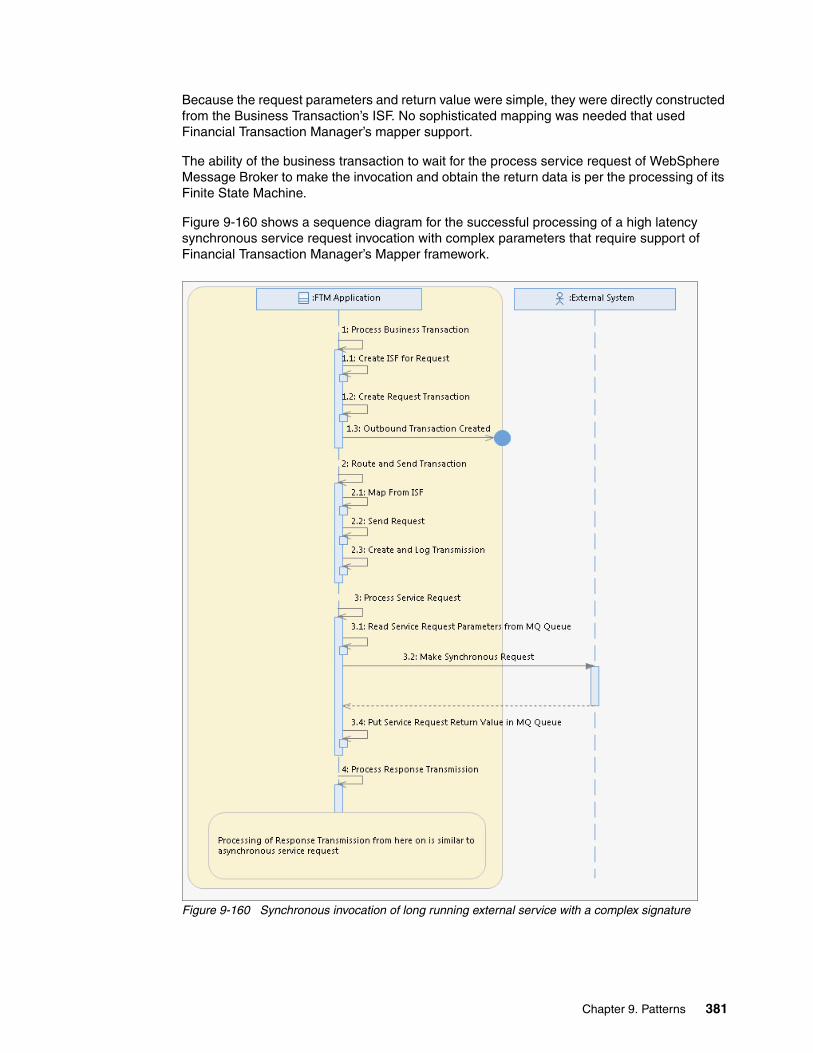
Because the request parameters and return value were simple, they were directly constructed from the Business Transaction’s ISF. No sophisticated mapping was needed that used Financial Transaction Manager’s mapper support.
The ability of the business transaction to wait for the process service request of WebSphere Message Broker to make the invocation and obtain the return data is per the processing of its Finite State Machine.
Figure 9-160 shows a sequence diagram for the successful processing of a high latency synchronous service request invocation with complex parameters that require support of Financial Transaction Manager’s Mapper framework.
Figure 9-160 Synchronous invocation of long running external service with a complex signature
Chapter 9. Patterns 381

The following process is shown in Figure 9-160 on page 381:
1. The Financial Transaction Manager application is processing a business message in a business transaction. As part of the action, handling wants to make a synchronous invocation to an external service.
The synchronous invocation is expected to take some time to complete processing, has complex request parameters and return values, and needs Financial Transaction Manager’s mapper support.
2. The business transaction makes a request transaction object in the same way that it creates one for making an asynchronous request invocation. The only difference is that instead of routing the request to the external application, the request is routed to an intermediate WebSphere MQ queue.
The service participant that is abstracting the WebSphere MQ queue to which the request is sent is a proxy for the external system.
3. The process service request (as in the previous case) is a WebSphere Message Broker flow and is part of the Financial Transaction Manager application.
It picks up the message from the intermediate WebSphere MQ queue, which was transformed by the outbound mapper that is associated with the request transaction and sends to the external service synchronously (by using the WebSphere Message Broker Nodes that is appropriate for the protocol of the service). After the reply arrives, it places the reply value in a WebSphere MQ queue (where Financial Transaction Manager is expecting the response). This WebSphere MQ queue also is part of the same proxy service participant and the channel that is supporting this WebSphere MQ acts as the inbound channel.
4. From the WebSphere MQ queue, processing of the reply value is done by Financial Transaction Manager’s physical transmission flow. Further processing of the reply value is similar to processing the incoming response as described for the asynchronous invocation.
9.9.2 Objects and object relationships
Figure 9-161 shows the various Financial Transaction Manager objects that are created during the invocation of the external service.
Figure 9-161 Objects and their relationships that are created during an external service invocation
In Figure 9-161, the business transaction object indicates the business transaction, which starts the external service invocation.
Request transaction is the transaction that is created for the external service invocation callout and its corresponding transmission is request transmission.
382 Financial Transaction Manager Technical Overview

The business transaction and request transaction have a business relationship, as shown in Figure 9-161 on page 382.
The response transaction is the transaction that is created for the incoming service response and it is an acknowledgement to the request transaction.
9.9.3 Detailed sequence diagram
The detailed sequence diagrams that correspond to the pattern highlight the interactions between the Financial Transaction Manager objects and components.
Invoking an asynchronous external servicein this section, we describe the interaction between the various Financial Transaction Manager’s components to realize an asynchronous external service invocation.
As with the high-level interactions, for more information about sending the outbound transaction that corresponds to the request, see 9.1, “Creation of outbound message or file pattern” on page 238.
In the following sections, we describe the processing of the incoming response. Along with the positive interaction, it shows the mapping that is aborted, no response from the external service, and correlation failure scenarios.
The Finite State Machines control the processing of the objects in the following sequence diagrams:
� Generic Outbound Transmission Finite State Machine for request transmission
� Generic Outbound Transaction Finite State Machine for request transaction
� Generic Inbound Transmission Finite State Machine for response transmission
� Generic Inbound Acknowledgement Transaction Finite State Machine for response transaction
For more information about the Generic Model Finite State Machines, see the Appendixes Appendix E: Generic Model section of the Financial Transaction Manager 2.1 Information Center.
Figure 9-162 on page 384 shows the sequence of interactions between the various Financial Transaction Manager components to achieve successful receipt of the response of the asynchronous external service invocation.
Note: All of the objects are created during all of the scenarios except for the synchronous invocation for services with simple signature.
Chapter 9. Patterns 383

Figure 9-162 Successful receipt of response to the asynchronous external service invocation
The following items are shown in Figure 9-162:
� The external system is the service from where the response is coming into Financial Transaction Manager.
� PT Flow is Financial Transaction Manager’s physical transmission flow, which reads input from the various protocols by using WebSphere Message Broker Input Nodes (such as WebSphere MQ Input node). It also starts the creation processes for the Transmission, Mapping to ISF, and Transaction objects.
� Mapper To ISF is the inbound mapper for the incoming response format. For more information about the Mapping interaction, see 9.5, “Transformation pattern” on page 318.
� Response transmission, transaction, request transaction, and business transaction are the Financial Transaction Manager objects, as described in 9.9.2, “Objects and object relationships” on page 382.
Figure 9-163 on page 385 shows the sequence of interactions between the various Financial Transaction Manager components for the mapping aborted case (during the receipt of the response of the asynchronous external service invocation).
384 Financial Transaction Manager Technical Overview

Figure 9-163 Mapping abort scenario during receipt of response to the asynchronous external service invocation
The following items are shown in Figure 9-163:
� The external System, PT flow, and the various transaction and transmission objects are as described in the previous flow.
� Operator is a person who uses the OAC to interact with the processing.
� E_HeartBeat events are fired by a heartbeat flow component of Financial Transaction Manager.
For more information about Heartbeats, see the Application Programming Heartbeat section of the Financial Transaction Manager 2.1 Information Center.
The timeout processing on an object is started on receipt of the heartbeat event. The criteria to process timeout is based on the timeout property setting on the object. The criteria is evaluated based on the current time stamp, context data in the heartbeat event, and timeout property of the object.
Figure 9-164 on page 386 shows the sequence of interactions between the various Financial Transaction Manager components in which no response is received from the external service after asynchronous external service invocation.
Chapter 9. Patterns 385

Figure 9-164 No response received scenario during asynchronous external service invocation
Objects and timeout information is the same as previously noted for the prior sequence.
Figure 9-165 on page 387 shows the sequence of interactions between the various Financial Transaction Manager components in which the correlation of the response to the request fails (during the receipt of the response of the asynchronous external service invocation).
386 Financial Transaction Manager Technical Overview

Figure 9-165 Response to request failure during receipt of response to asynchronous external service invocation
As the response fails to correlate to the request, the request object times out waiting for correlation, as shown in Figure 9-165.
Invoking a synchronous external serviceIn this section, we describe the interaction between the various Financial Transaction Manager’s components to realize a synchronous external service invocation.
Figure 9-166 on page 388 shows the sequence of interactions between the various Financial Transaction Manager components in which the business transaction is making a simple and long-running synchronous service invocation to an external system.
Chapter 9. Patterns 387

Figure 9-166 Simple and long-running synchronous external service invocation
Figure 9-166 includes the following features:
� The business transaction is the Financial Transaction Manager transaction object that is processing the business functionality that is interested in making the external invocation. Its lifecycle is controlled by Finite State Machine, as shown in Figure 9-170 on page 391.
� The process service request is a WebSphere Message Broker flow that helps make the synchronous invocation and communicates with the business transaction processing. To use the synchronous invocation, the correct WebSphere Message Broker Node can be used, depending on the protocol of the service. For example, if a Web Service must be started, WebSphere Message Broker HTTPRequest Node can be used.
� The external system is the system that hosts the simple external service.
Figure 9-167 on page 389 shows the sequence of interactions between the various Financial Transaction Manager components. Specifically, when the business transaction is making a long-running synchronous service invocation to an external system with a complex signature that requires the use of Financial Transaction Manager’s mapping capabilities.
388 Financial Transaction Manager Technical Overview

Figure 9-167 Long-running synchronous external service invocation with a complex signature
As shown in Figure 9-167, the business transaction intends on making a synchronous service request to the external service. The format of the service request is complex and uses the Financial Transaction Manager’s mapping support; therefore, it treats the synchronous service request as an asynchronous service by employing an intermediate proxy Service Participant.
In the configuration data, service participant and channel definition are configured to the proxy instead of the actual external service. The proxy processing is taken care of by the process service request flow.
As shown in Figure 9-167, before process service request processing starts, the business transaction treats the invocation as an asynchronous service and employs the interaction as described for the asynchronous service request.
Chapter 9. Patterns 389

After the service request is mapped and delivered into the proxy, the process service request flow then makes the actual synchronous service request call to the external service. The flow then focuses on getting the reply data inputs into the channel for the proxy service participant.
Physical transmission flow then starts and completes the processing from the business transaction perspective as though it was an asynchronous response that is received.
9.9.4 Object lifecycle diagram
The object lifecycle diagram that is shown in this section shows a portion of entire object lifecycle that is specific to the processing of external service invocation.
Figure 9-168 shows the lifecycle of the response transaction object, as indicated by the sequence diagrams.
Figure 9-168 Response transaction object lifecycle
Figure 9-169 on page 391 shows the lifecycle of the request transaction object, as indicated by the sequence diagrams for asynchronous requests shown earlier. As shown in Figure 9-169 on page 391, the lifecycle pertains only to the response processing leg. For more information about request processing, see 9.1, “Creation of outbound message or file pattern” on page 238.
More information: For more for information about the Generic Model Finite State Machines, see the Appendixes Appendix E: Generic Model section of the Financial Transaction Manager 2.1 Information Center.
390 Financial Transaction Manager Technical Overview
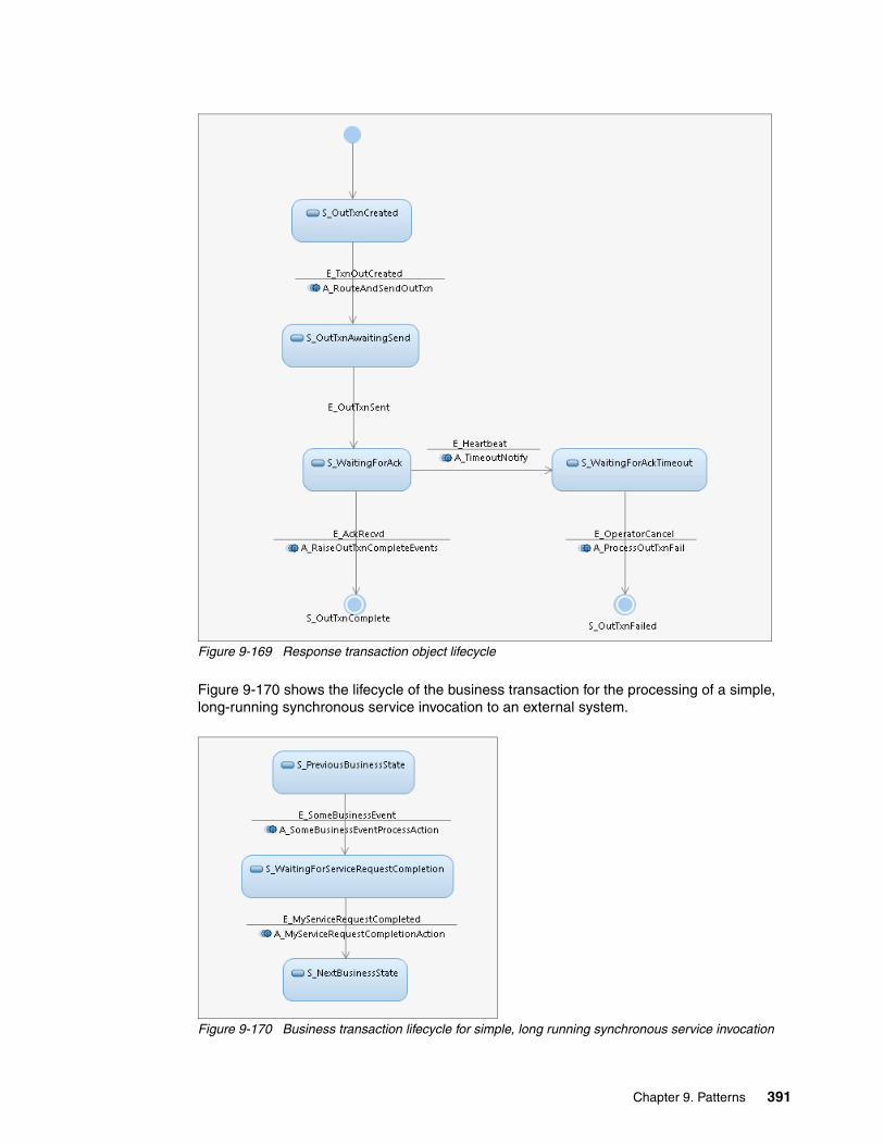
Figure 9-169 Response transaction object lifecycle
Figure 9-170 shows the lifecycle of the business transaction for the processing of a simple, long-running synchronous service invocation to an external system.
Figure 9-170 Business transaction lifecycle for simple, long running synchronous service invocation
Chapter 9. Patterns 391
In Figure 9-170 on page 391, S_PreviousBusinessState, denotes the state of the business transaction before the external invocation was needed. As part of the E_SomeBusinessEvent processing, the external system’s synchronous service is to be started. This is done as part of the A_SomeBusinessEventProcessAction. When the synchronous request is being sent, the business transaction moves into S_WaitingForServiceRequestCompletion (a waiting state).
When the synchronous service invocation is completed and E_MyServiceRequestCompleted event is raised, the business transaction then moves to the next state (S_NextBusinessState). Then, the received response is processed.
9.9.5 Finite State Machine
For more information about the differences between the object lifecycle diagrams that were described in 9.9.4, “Object lifecycle diagram” on page 390 and their corresponding Finite State Machines, see the Appendixes Appendix E: Generic Model section of the Financial Transaction Manager 2.1 Information Center.
9.9.6 Process highlights
This pattern is concerned with how a business transaction in Financial Transaction Manager can make an external service invocation to a service hosted in an external system.
The external service invocation can be synchronous or asynchronous in nature.
Making an asynchronous invocation consists of the following parts:
� Making the outgoing request to the external system.
� Receiving the response from the external system, correlating it back to the outgoing request, and flagging the business transaction object.
While making an asynchronous service invocation, the business transaction object that represents processing the business message in Financial Transaction Manager interacts with separate transaction objects. These transaction objects correspond to processing the outgoing request and the incoming response that is referred to as the request and the response transaction objects.
Processing the request and response transactions are specified by a set of Generic Finite State Machines as provided by Financial Transaction Manager. The following Generic Finite State Machines are available:
� Generic Outbound Transmission Finite State Machine for request transmission
� Generic Outbound Transaction Finite State Machine for request transaction
� Generic Inbound Transmission Finite State Machine for response transmission
� Generic Inbound Acknowledgement Transaction Finite State Machine for response transaction
Making synchronous service invocations include some consideration because of their blocking nature. It is not advisable to block the events processing flow that runs the actions as part of business transaction processing. Therefore, if the synchronous invocation can have a longer latency, it is advisable to decouple the business transaction processing in the events thread to make the actual invocation.
By using appropriate Finite State Machine modeling, the business transaction processing can wait for the synchronous invocation to complete.
392 Financial Transaction Manager Technical Overview

Depending on the complexity of the signature of the external service, it might be required to use Financial Transaction Manager’s mapping facilities. If so, the synchronous service invocation can be modeled as asynchronous (with an intermediate proxy service participant making the actual invocation and adapting the asynchronous call to synchronous).
9.9.7 Pattern interaction
This patterns is used in the larger context of processing a business message in a business transaction.
To make a request to an external system, it uses patterns that are described in 9.1, “Creation of outbound message or file pattern” on page 238. After the message is processed by the external system, this pattern explains the processing of the response.
In addition, as part of the mapping from ISF to the external system’s format (during the request phase and on mapping from the external system’s format to ISF during response processing), it uses the mapping pattern as described in 9.5, “Transformation pattern” on page 318.
If the started external service expects batched transactions or returns a bulked response, this pattern can use the pattern that is described in 9.6, “Debulking pattern” on page 338 and the pattern that is described in 9.7, “Bulking pattern” on page 348.
9.10 Hosting services pattern
This pattern describes how Financial Transaction Manager can host a business service. Depending on the business requirements of the hosted service, synchronous and asynchronous services can be supported.
Chapter 9. Patterns 393
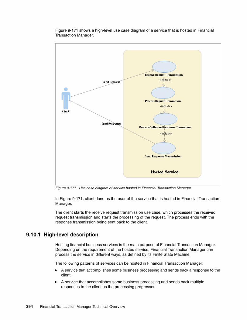
Figure 9-171 shows a high-level use case diagram of a service that is hosted in Financial Transaction Manager.
Figure 9-171 Use case diagram of service hosted in Financial Transaction Manager
In Figure 9-171, client denotes the user of the service that is hosted in Financial Transaction Manager.
The client starts the receive request transmission use case, which processes the received request transmission and starts the processing of the request. The process ends with the response transmission being sent back to the client.
9.10.1 High-level description
Hosting financial business services is the main purpose of Financial Transaction Manager. Depending on the requirement of the hosted service, Financial Transaction Manager can process the service in different ways, as defined by its Finite State Machine.
The following patterns of services can be hosted in Financial Transaction Manager:
� A service that accomplishes some business processing and sends back a response to the client.
� A service that accomplishes some business processing and sends back multiple responses to the client as the processing progresses.
394 Financial Transaction Manager Technical Overview

� A service that behaves in a “fire and forget” manner, which accomplishes some business processing but does not respond back to the client with any further status.
� A service that might have batches of transactions and the business processing processes the entire batch (and might send back a single response or a batch of responses).
The service processing can be a single step where some business logic is executed. As well, it can be more complicated having multiple steps with many other outgoing external service invocations.
In this section, a service that is hosted in Financial Transaction Manager (which performs some business processing and sends back a response on completion to the client) is shown.
All other variations can be easily extended thereafter by studying this pattern and some other related patterns, such as the pattern that is described in 9.7, “Bulking pattern” on page 348 and the pattern that is described in 9.6, “Debulking pattern” on page 338.
From a business perspective, the hosted service needs a synchronous or asynchronous behavior. Though the processing of these scenarios are similar, some differences arise because of the protocols that are used for synchronous or asynchronous communication.
For example, for a synchronous service call, Financial Transaction Manager might need to support Web Services protocol. Therefore, Financial Transaction Manager must receive inputs that use WebSphere Message Broker Nodes that are relevant to those protocols. Thereafter, it must send back the response to the client, which ensures that the client receives the response in its thread of invocation.
However, for an asynchronous service call, no such restrictions exist. By using WebSphere Message Broker MQ Nodes, such a service can be easily implemented.
In this section, we describe high-level interactions between the client and Financial Transaction Manager to host a service that processes the business logic and replies in the following ways:
� Replies back to the client, the response asynchronously� Replies back to the client, the response synchronously
In the sequence diagrams that are shown in this section, request transaction denotes the incoming service invocation master transaction. The response transaction is the response that is sent back to the client.
Chapter 9. Patterns 395
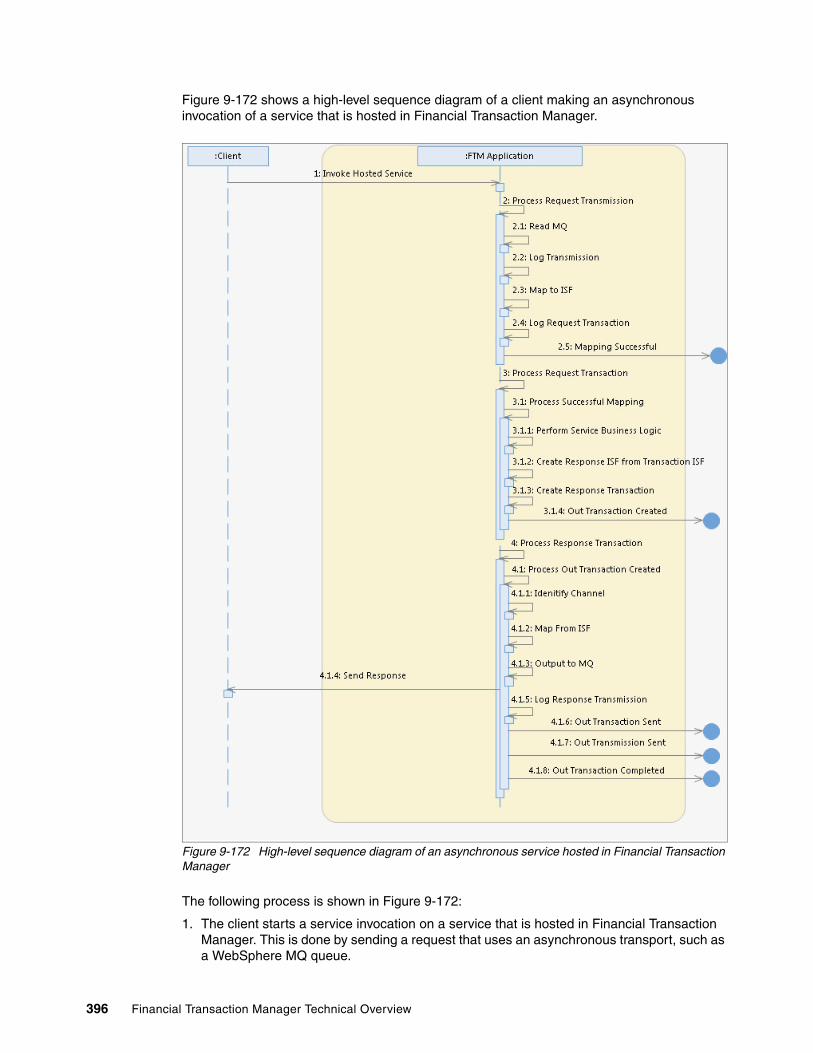
Figure 9-172 shows a high-level sequence diagram of a client making an asynchronous invocation of a service that is hosted in Financial Transaction Manager.
Figure 9-172 High-level sequence diagram of an asynchronous service hosted in Financial Transaction Manager
The following process is shown in Figure 9-172:
1. The client starts a service invocation on a service that is hosted in Financial Transaction Manager. This is done by sending a request that uses an asynchronous transport, such as a WebSphere MQ queue.
396 Financial Transaction Manager Technical Overview

2. Financial Transaction Manager handles the incoming request transmission by first reading it from the WebSphere MQ queue. The request is read by a WebSphere Message Broker Node, such as MQInput. Then, a transmission object for the request is created, which is called request transmission object. Then, the correct mapper (which is based on the inbound channel definition) maps the transmission object to ISF. Thereafter, the corresponding request transaction object also is created.
The request transaction object is the master transaction object and its Finite State Machine determines the processing of the started service.
3. Depending on the Finite State Machine of the request transaction, the processing is started. In Figure 9-172 on page 396, this processing is started on the completion of the mapping when the Mapping Completed event is raised.
The request transaction processing can be as simple or as complex as possible. This is dependent on its Finite State Machine.
4. After the business processing of the request transaction is completed, the request transaction is ready to return the response to the client.
5. The request transaction processing creates the ISF for the response message and constructs the response transaction object.
The response transaction object corresponds to the acknowledgement that must be returned to the client. The response transaction’s processing is dependent on the Generic Outbound Transaction Finite State Machine with Fire and Forget semantics.
Request transaction processing can further help in routing the response back to the client based on the service participant configuration of the client. After all, the response must be sent back to the originator of the request.
One way to do this is for the request transaction to link back to its request transmission, which includes the ID of the configuration for the inbound channel. Based on this channel configuration, the service participant ID of the client can be acquired.
The request transaction then raises the Out Transaction Created event, which sets the service participant ID of the client as a context.
6. Generic Outbound Transaction Finite State Machine takes over the processing of the response transaction. Based on the identified service participant (which is set in the context of the incoming event), the out channel configuration is retrieved, from which the outbound mapper information is acquired.
After mapping the response ISF to the external format, the outbound mapper sends the transmission to the client. This is done by using an asynchronous transport, such as WebSphere MQ queue that uses WebSphere Message Broker MQOutput Node.
The actual WebSphere Message Broker flow name (o send the actual outbound transmission is configured by using the outbound channel’s transport property. Thereafter, it raises the appropriate events. This sends the out transaction and transmission and indicates the completion of the response transaction.
For more information about sending responses, see 9.1, “Creation of outbound message or file pattern” on page 238.
For more information about mapping, see 9.5, “Transformation pattern” on page 318.
For more information about WebSphere Message Broker Nodes, see the Reference Message flow development Built-in nodes section of the WebSphere Message Broker 7.0 information center.
Chapter 9. Patterns 397

Figure 9-173 shows a high-level sequence diagram of a client that is making a synchronous invocation to a service that is hosted in Financial Transaction Manager.
Figure 9-173 High-level sequence diagram of a synchronous service
In Figure 9-173, the processing is similar to the asynchronous case, except for the indicated areas in the figure (blue boxes). The key points that are different are the protocols of the transport (on which the invocation request arrives from the client and on which the response is sent back). In the asynchronous case, WebSphere MQ queues were used; but for synchronous service, Web Services over HTTP is used.
The following indicated areas are shown in Figure 9-173:
� Incoming transmission from the client is read by the WebSphere Message Broker HTTP Input Node.
For more information about the handling of Web Services in WebSphere Message Broker, see the Developing message flow applications Connecting client applications Processing Web services messages section of the WebSphere Message Broker 7.0 information center.
398 Financial Transaction Manager Technical Overview

� The HTTP Request ID of the incoming HTTP message is stored with the request transmission object in its UID property. This is needed later for correlation to the HTTP request when the response is returned.
� Further processing is similar to the asynchronous case (until the point of returning the response).
� The response must be returned by the HTTP Reply WebSphere Message Broker Node. For the HTTP Reply Node to correlate to the original HTTP Request, it must be fed the original HTTP Request ID. This ID can be retrieved through the association of the response transaction to the request transmission.
� The HTTP Reply Node must be started to send the transmission. The outbound channel has a configuration (which is called transport) that stores the name of the WebSphere Message Broker Flows that are to be used to send the transmission. By choosing its value as HTTP, the HTTP Reply Node can be chosen, which then sends the message back to the client.
� Further processing in the sequence is similar to the asynchronous case.
9.10.2 Objects and object relationships
Figure 9-174 shows the various Financial Transaction Manager objects that are created during the running of this pattern.
Figure 9-174 Financial Transaction Manager objects and their relationships
In Figure 9-174, request transaction is the master transaction object, which processes the hosted service. Its Finite State Machine drives the processing of the hosted service. The request transmission is its transmission object.
The response transaction is the transaction object that corresponds to the response that is returned to the client after the invocation completion of the hosted service. The response transmission is the outgoing response transmission record. Generic outgoing acknowledgement is responsible for processing the response transaction.
9.10.3 Detailed sequence diagram
The detailed sequence diagrams that correspond to the pattern highlight the interactions between the Financial Transaction Manager objects and components.
Figure 9-175 on page 400 shows the low-level interaction between the Financial Transaction Manager components to realize an asynchronous service hosting.
Chapter 9. Patterns 399

Figure 9-175 Sequence diagram depicting asynchronous service hosting
Figure 9-175 includes the following information:
� The client is the user of the service that is hosted in the Financial Transaction Manager and sends the request.
400 Financial Transaction Manager Technical Overview

� PT Flow is the physical transmission flow that takes input from the physical input of the message. This is done by using various WebSphere Message Broker nodes, such as WebSphere MQ Input Nodes) to read the message from the client. The node then starts the inbound mapper and the creation of the request transmission and transaction objects.
� The request transaction object is the Financial Transaction Manager transaction object that is responsible for processing the service that is hosted. It also corresponds to a Finite State Machine that determines the processing.
� After the business logic is completed, the request transaction object creates the request response object for returning the response to the client. The response transaction object is controlled by the Generic Outbound Transaction Finite State Machine.
� Request transaction helps route the response transaction by helping it determine the service participant ID of the client. This ID is then passed in the context data for the E_TxnOutCreated event. Routing logic reviews this service participant for outbound channel definition, which is used to the determine the outbound mapper definition and other relevant details.
For more information about Generic Outbound Transaction Finite State Machine processing, see 9.1, “Creation of outbound message or file pattern” on page 238.
For more information about mapping, see 9.5, “Transformation pattern” on page 318.
Figure 9-176 on page 402 shows the low-level interaction between the Financial Transaction Manager components to realize a synchronous service hosting.
Chapter 9. Patterns 401

Figure 9-176 Sequence diagram depicting synchronous service hosting
In Figure 9-176, all of the objects and interactions are similar to the asynchronous case, except for the indicated areas in the figure (blue box).
9.10.4 Object lifecycle diagram
The object lifecycle diagram that is shown in this section shows a portion of the entire object lifecyle that is specific to the hosted service processing.
402 Financial Transaction Manager Technical Overview
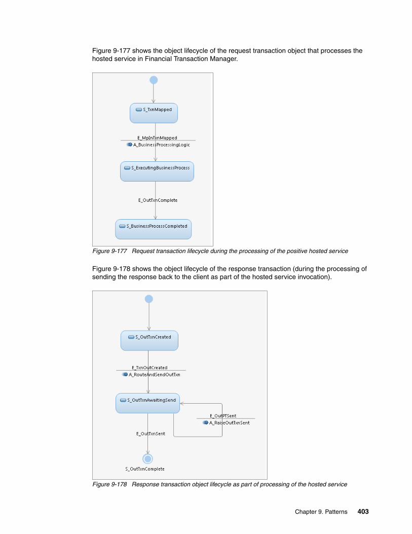
Figure 9-177 shows the object lifecycle of the request transaction object that processes the hosted service in Financial Transaction Manager.
Figure 9-177 Request transaction lifecycle during the processing of the positive hosted service
Figure 9-178 shows the object lifecycle of the response transaction (during the processing of sending the response back to the client as part of the hosted service invocation).
Figure 9-178 Response transaction object lifecycle as part of processing of the hosted service
Chapter 9. Patterns 403

9.10.5 Finite State Machine
For more information about the differences between the Object Lifecycle diagrams that were described in 9.10.4, “Object lifecycle diagram” on page 402 and their corresponding Finite State Machines can be found in the Appendixes Appendix E: Generic Model section of the Financial Transaction Manager 2.1 Information Center.
9.10.6 Process highlights
This pattern is concerned with how a client can start a service that is hosted in Financial Transaction Manager. Hosting a financial business service is Financial Transaction Manager’s purpose.
The hosted service can be of any complexity, such as the following complexities:
� Single step processing, which results in a single response back to the client
� Multiple step processing, with many further external service invocations (having single or multiple responses back to the client)
� Processing batched transactions
The actual processing of the hosted service is controlled by the transaction’s Finite State Machine model.
In addition, the hosted service can be synchronous or asynchronous (from the perspective of the client that is making the invocation).
A service that is hosted by Financial Transaction Manager can be synchronous or asynchronous, depending on the protocols that are used to access the service. For instance, WebSphere MQ queues allow accessing the service asynchronously, whereas the service can be designed as synchronous Web Services.
9.10.7 Pattern interaction
This patterns is used in the larger context of making financial business or utility functionality available to the clients.
The clients can be the user applications (such as channel applications) or other business services that use utility services.
This pattern can be composed by using many other patterns described in this book. Some of the related patterns are the creation of outbound message or file, bulking, debulking, and transformation.
9.11 Collating information from several sources pattern
In certain circumstances, a complete financial transaction can consist of data that originates from separate applications, customers, networks, and so forth, and can arrive at different times. This means that transactions must be paused and then waits for the entire data set to be received, combined, and then released for further processing.
404 Financial Transaction Manager Technical Overview

The way this is achieved within Financial Transaction Manager is to designate the primary message as a master transaction and the subsequent messages as child transactions. The master transaction is updated with data from the child transactions and, when all of the child transactions are received, they are released for further processing.
The use case for this pattern is shown in Figure 9-179.
Figure 9-179 Collating Data use case
9.11.1 High-level description
This pattern focuses on the interaction of the transactions that are received by Financial Transaction Manager. The mechanism of receiving the data and physical transmission processing is not described here.
This pattern includes the following scenarios:
� The master transaction arrives and all of the associated child transactions are present in the Financial Transaction Manager Database.
� The master transaction arrives and not all of the associated child transactions are present in the Financial Transaction Manager Database.
� An associated child transaction arrives and the master transaction is not present in the Financial Transaction Manager Database.
� An associated child transaction arrives and the master transaction is present in the Financial Transaction Manager Database.
Common data: The Master and associated transactions must contain some common data that can be used to link them.
Chapter 9. Patterns 405

Scenario 1Figure 9-180 shows the high-level description for scenario 1.
Figure 9-180 High-level description for master transaction with all associated transactions
In this scenario, the following process occurs:
1. The master transaction arrives and an action searches for its associated transactions.
2. The action identifies that all of the transactions that are associated with the master transaction are present, collects the required data, and updates the master transaction.
3. The master transaction continues processing.
406 Financial Transaction Manager Technical Overview
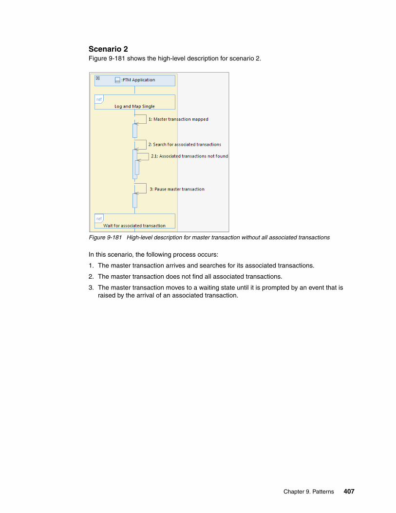
Scenario 2Figure 9-181 shows the high-level description for scenario 2.
Figure 9-181 High-level description for master transaction without all associated transactions
In this scenario, the following process occurs:
1. The master transaction arrives and searches for its associated transactions.
2. The master transaction does not find all associated transactions.
3. The master transaction moves to a waiting state until it is prompted by an event that is raised by the arrival of an associated transaction.
Chapter 9. Patterns 407

Scenario 3Figure 9-182 shows the high-level description for scenario 3.
Figure 9-182 High-level description for associated transaction without a master transaction
In this scenario, the following process occurs:
1. The associated transaction arrives and searches for the master transaction.2. The master transaction is not present.3. The associated transaction moves to an arrived state, waiting for the master transaction.
408 Financial Transaction Manager Technical Overview

Scenario 4Figure 9-183 shows the high-level description for scenario 4.
Figure 9-183 High-level description for associated transaction with a master transaction
In this scenario, the following process occurs:
1. The associated transaction arrives and searches for the master transaction.
2. The master transaction is present.
3. The associated transaction raises an event to prompt the master transaction and moves to an arrived state.
4. The master transaction searches for associated transactions and, if all present, continues processing. If not all of the associated transactions are present, it returns to a waiting state.
9.11.2 Objects and object relationships
The Financial Transaction Manager objects that are identified in this pattern consist of the master transaction and its associated transactions, as shown in Figure 9-184.
Figure 9-184 Collating Data Object/Object Relationship
Chapter 9. Patterns 409

9.11.3 Detailed sequence diagram
This pattern includes the following scenarios:
� The master transaction arrives and all of the associated child transactions are present. � The master transaction arrives and not all of the associated child transactions are present.� An associated child transaction arrives and the master transaction is not present. � An associated child transaction arrives and the master transaction is present.
The detailed sequence diagram for scenario 1, a master transaction arrives and all associated transaction are present, is shown in Figure 9-185.
Figure 9-185 Master transaction with all associated transactions
410 Financial Transaction Manager Technical Overview

The detailed sequence diagram for scenario 2, a master transaction arrives but some associated transactions are missing, is shown in Figure 9-186.
Figure 9-186 Master transaction without all associated transactions
The detailed sequence diagram for scenario 3, an associated transaction arrives but the master transaction is not yet present, is shown in Figure 9-187.
Figure 9-187 Associated transaction without master transaction
Chapter 9. Patterns 411

As shown in Figure 9-188, the detailed sequence diagram for scenario 4 shows that an associated transaction arrives and the master transaction is present. Figure 9-188 also shows the effect that the event that the associated transaction raises has on the master transaction.
Figure 9-188 Associated transaction with master transaction
412 Financial Transaction Manager Technical Overview

9.11.4 Object lifecycle diagram
The objects that are identified in this transaction (the master and associated transactions) have different object lifecycles. The master transaction’s lifecycle is shown in Figure 9-189.
Figure 9-189 Master transaction object lifecycle diagram
The child transaction lifecycle is simpler, as shown in Figure 9-190.
Figure 9-190 Child transaction object lifecycle diagram
9.11.5 Finite State Machine
The Finite State Machine for the master and child transactions can be combined or be separate. An example of a snippet of a Finite State Machine for the master transaction is shown in Figure 9-191 on page 414.
Chapter 9. Patterns 413
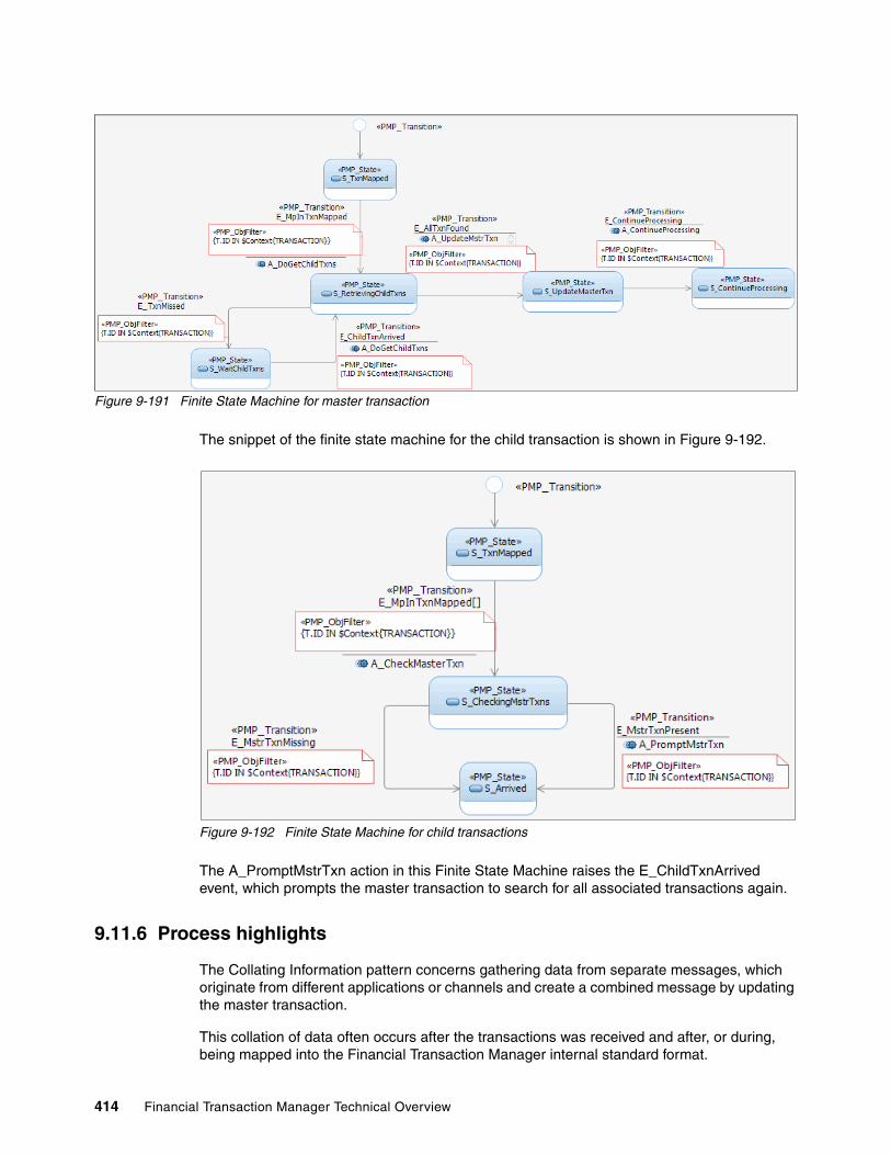
Figure 9-191 Finite State Machine for master transaction
The snippet of the finite state machine for the child transaction is shown in Figure 9-192.
Figure 9-192 Finite State Machine for child transactions
The A_PromptMstrTxn action in this Finite State Machine raises the E_ChildTxnArrived event, which prompts the master transaction to search for all associated transactions again.
9.11.6 Process highlights
The Collating Information pattern concerns gathering data from separate messages, which originate from different applications or channels and create a combined message by updating the master transaction.
This collation of data often occurs after the transactions was received and after, or during, being mapped into the Financial Transaction Manager internal standard format.
414 Financial Transaction Manager Technical Overview

The transactions that are received wait for the complete set of transactions to arrive. There can be a sizeable delay or the transaction might not arrive at all. In this case, a manual or automatic exception process must be considered to raise an alert to an operator.
Another consideration is that the transactions must be linked during the mapping or intrinsically in the data. It also must be possible to identify the number of associated transactions from the received message; for example, a sequence number or by some other method.
9.11.7 Pattern interaction
This pattern interacts with any pattern that deals with the reception of transactions, such as the pattern that is described in 9.6, “Debulking pattern” on page 338 or how they are mapped, such as the pattern that is described in 9.5, “Transformation pattern” on page 318.
If an associated transaction fails to arrive, this pattern might also interact with patterns that are associated with alerts and errors, as described in 9.15, “Error handling and alerts patterning” on page 438.
9.12 Scheduled activity pattern
Many applications require triggering activities at scheduled times, such as during the following activities:
� Sending transmissions to a gateway at its cut-off time
� Sending heartbeat ping messages to an external system to monitor its availability
� Sending external events to a business activity monitoring component, such as IBM Business Monitor
This pattern describes how Financial Transaction Manager can be used to start such scheduled activities.
Figure 9-193 shows a simple use case diagram in which a scheduled activity is sending a transaction to an external system periodically.
Figure 9-193 Use case diagram of a scheduled activity
Although the use case is indicating a specific activity (sending the transaction), this pattern can be used for any scheduled task.
Chapter 9. Patterns 415
9.12.1 High-level description
As part of processing of financial applications, activities must be completed at scheduled times or periodically. Financial Transaction Manager provides the following functions to allow such processing:
� Scheduler tasks� Heartbeat events and flows� Schedule specifications
A scheduler task is an abstraction of any processing that must be performed according to some schedule. Because the scheduler task is abstracting the processing, it is considered a lifecycle object and implicitly has a Finite State Machine associated with it. The Finite State Machine defines the actual activities that needs to be performed. In Financial Transaction Manager, the scheduler task is represented as part of the operational data and has records pertaining to it in the SCHEDULER_TASK_BASE table with corresponding associations to the OBJ_BASE records.
This entity includes the following key attributes, which have significance during the scheduled task processing:
� Task time, which indicates the time of the current task that was run� Timeout (from OBJ_BASE), which specifies the next scheduled time to perform the activity
Scheduler tasks that are related records are typically created when the scheduled activity is installed, which can be performed as part of an application initialization script and run after all the configuration data is imported.
Heartbeat events are the events that are based on the Common Business Event model and are raised by Financial Transaction Manager by using a Heartbeat flow. The following kinds of Heartbeat events are available:
� Heartbeat start events (E_HeartbeatStart)� Heartbeat events (E_Heartbeat)
Heartbeat start events indicate the start of the scheduled processing. As part of processing for this event, initializations for the scheduler tasks can be set up by an action at any time.
Heartbeat events are the periodic events that are sent by the heartbeat flow and as part of its context and contains the current time stamp. Through Finite State Machine orchestration, scheduler tasks can listen on these events and, based on some evaluation of criteria, perform the actual scheduled activity.
Heartbeat flow is a WebSphere Message Broker flow that raises the Heartbeat events on a regular basis. At the start of the flow, the Heartbeat flow raises E_HeartbeatStart. From that point forward, it periodically raises E_Heartbeat. Financial Transaction Manager features a sample heartbeat flow that raises the heartbeat events every 60 seconds.
For more information about Heartbeat events and flows, see the Financial Transaction Manager 2.1 Information Center and browse to Application Programming Heartbeat.
Schedule specifications are the schedule configuration information by which the scheduler task evaluates and bases when to run the next activity. All the schedule specification is abstracted under the concept of a calendar group that is held inside the configuration data as part of CALENDAR_GROUP table. Scheduler task associates to this entity to obtain the schedule configuration information at run time. Calendar group includes specifications of the individual schedule entries that denote a specific schedule (including specific operating hours, the period to wait till the next activity, and so on).
416 Financial Transaction Manager Technical Overview

The set up of the calendar group, scheduled entry, and so on, are done as part of configuration modeling in Rational Software Architect and are exported into the configuration data. By looking at the association of the scheduler task with its associated calendar group and then choosing the best schedule entry, the time for the next scheduled action can be determined.
Figure 9-194 shows a high-level interaction between an Financial Transaction Manager application and an external system. In this case, the Financial Transaction Manager application periodically sends the external system a transaction.
Figure 9-194 Application periodically performing an activity
Chapter 9. Patterns 417
Figure 9-194 shows the following activities:
� At the start of the Financial Transaction Manager application, the heartbeat flow is started and the heartbeat started event is raised.
� On receipt of the heartbeat started event, the scheduler task processing (as defined by its Finite State Machine) fetches the associated calendar group object. From the calendar group event, the schedule entry is gathered. The scheduled entry defines the period or frequency of performing the activity; in this case, sending the transaction to the external system.
Based on the gathered period, the scheduler task is started so that the next transaction is sent to the external system at the current time plus the period.
This logic can be anything to determine the next time when the scheduled activity must be performed.
The time stamp is then stored in the scheduler task’s timeout property.
� From this point on, Heartbeat flow periodically generates the heartbeat event. Within the heartbeat event is stored the current time in the event context named NOW.
� Scheduler task processing then handles the received heartbeat event and checks if the timeout elapsed. If the timeout elapsed, scheduler task kick starts the periodic activity processing; in this case, sending a transaction to an external system.
After performing the scheduled activity, it resets the timeout as earlier based on the configured schedule entries.
This entire process repeats while the heartbeat messages are generated.
Stopping the Scheduler Task is possible based on the set up of its Finite State Machine.
9.12.2 Objects and object relationships
In this pattern, scheduler task is the main object and controls the processing of the scheduled activity. A scheduler task object is similar to any other lifecycle object, such as a transaction or a transmission, and has type and subtype attributes.
The Finite State Machines often are configured based on the type and subtype attributes.
9.12.3 Detailed sequence diagram
The detailed sequence diagrams that correspond to the pattern highlight the interactions between the Financial Transaction Manager objects and components.
Figure 9-195 on page 419 shows the low-level sequence diagram. The diagram details the interaction between the various Financial Transaction Manager components to realize the scheduled activity pattern.
418 Financial Transaction Manager Technical Overview
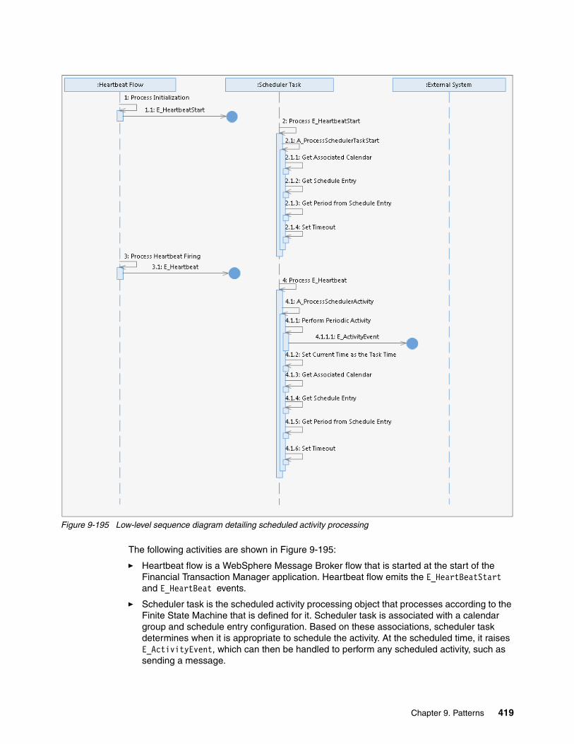
Figure 9-195 Low-level sequence diagram detailing scheduled activity processing
The following activities are shown in Figure 9-195:
� Heartbeat flow is a WebSphere Message Broker flow that is started at the start of the Financial Transaction Manager application. Heartbeat flow emits the E_HeartBeatStart and E_HeartBeat events.
� Scheduler task is the scheduled activity processing object that processes according to the Finite State Machine that is defined for it. Scheduler task is associated with a calendar group and schedule entry configuration. Based on these associations, scheduler task determines when it is appropriate to schedule the activity. At the scheduled time, it raises E_ActivityEvent, which can then be handled to perform any scheduled activity, such as sending a message.
Chapter 9. Patterns 419

� The processing is as defined in the sequence diagram. Scheduler task handles the E_HeartBeat only if the current time in the event elapsed the configured timeout that was set in it. The timeout process is not indicated in Figure 9-195 on page 419.
9.12.4 Object lifecycle diagram
Figure 9-196 shows the object lifecycle diagram of a scheduler task.
Figure 9-196 Object lifecycle of a scheduler task
The scheduler task has only a single state during which it processes the received heartbeat events.
9.12.5 Finite State Machine
Figure 9-197 shows the Finite State Machine of the scheduler task object.
Figure 9-197 Object lifecycle of the scheduler task
420 Financial Transaction Manager Technical Overview
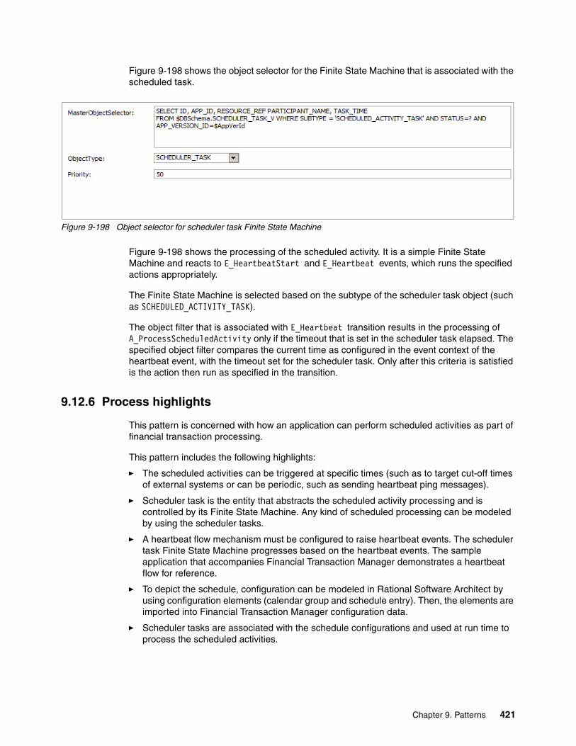
Figure 9-198 shows the object selector for the Finite State Machine that is associated with the scheduled task.
Figure 9-198 Object selector for scheduler task Finite State Machine
Figure 9-198 shows the processing of the scheduled activity. It is a simple Finite State Machine and reacts to E_HeartbeatStart and E_Heartbeat events, which runs the specified actions appropriately.
The Finite State Machine is selected based on the subtype of the scheduler task object (such as SCHEDULED_ACTIVITY_TASK).
The object filter that is associated with E_Heartbeat transition results in the processing of A_ProcessScheduledActivity only if the timeout that is set in the scheduler task elapsed. The specified object filter compares the current time as configured in the event context of the heartbeat event, with the timeout set for the scheduler task. Only after this criteria is satisfied is the action then run as specified in the transition.
9.12.6 Process highlights
This pattern is concerned with how an application can perform scheduled activities as part of financial transaction processing.
This pattern includes the following highlights:
� The scheduled activities can be triggered at specific times (such as to target cut-off times of external systems or can be periodic, such as sending heartbeat ping messages).
� Scheduler task is the entity that abstracts the scheduled activity processing and is controlled by its Finite State Machine. Any kind of scheduled processing can be modeled by using the scheduler tasks.
� A heartbeat flow mechanism must be configured to raise heartbeat events. The scheduler task Finite State Machine progresses based on the heartbeat events. The sample application that accompanies Financial Transaction Manager demonstrates a heartbeat flow for reference.
� To depict the schedule, configuration can be modeled in Rational Software Architect by using configuration elements (calendar group and schedule entry). Then, the elements are imported into Financial Transaction Manager configuration data.
� Scheduler tasks are associated with the schedule configurations and used at run time to process the scheduled activities.
Chapter 9. Patterns 421

9.12.7 Pattern interaction
This pattern is one of the base patterns. Higher-level processing can be built by using this pattern.
A pattern that often interacts with scheduled activity is the store and release pattern.
Figure 9-199 shows the sequence diagram and how scheduled activity can be used in relation to the store and release pattern.
Figure 9-199 The use of scheduled activity in relation to the store and release pattern
Figure 9-199 shows the following actions:
� Transactions are started to be sent out as explained in the pattern (in this case, A transaction is to be transmitted but is not allowed, from the store and release pattern, so the transaction is held).
� The held transactions (warehoused transactions) are then triggered to be sent out when the service participant is open. The service participant must be triggered to realize that it is open and must run the transmission of its warehoused transaction.
� This triggering is accomplished by using a pattern as indicated in the sequence diagram. When the service participant is open (cut-off time), these triggers are sent out of the scheduled task pattern at scheduled times.
� After receiving the trigger, the service participant continues on with its processing, as explained in the store and release pattern’s Transaction Release sequence diagram.
422 Financial Transaction Manager Technical Overview

9.13 Scheduled expectation pattern
This pattern describes the monitoring of a process that raises certain events to be issued at a certain time. This type of pattern is common in settlement mechanisms; for example, awaiting an end-of-day reconciliation file or the delivery of direct debit instructions. This pattern also can be used to monitor client interfaces; for example, the delivery of a file at an expected time.
The timeout for the Scheduler Task is calculated with reference to any Calendar Group or Schedule that was defined against it. If the expected event does not occur before the timeout is reached, an alert is raised to the operator for investigation.
Figure 9-200 shows the use case for this pattern.
Figure 9-200 High-level use case for scheduled expectation
9.13.1 High-level description
The high-level description for this pattern consists of the following use cases:
� Event that is monitored for is detected � Event that is monitored for is not detected before the timeout
The Scheduler Task object is a Financial Transaction Manager object and can include finite state machines that describe state changes, the events that cause them, and the action that is triggered by them.
The Scheduled Task object is not dependent on any other Financial Transaction Manager object; for example, Service Participant and transaction. It waits for a specific event only. The event can be fine-grained, for example, for a particular file name, and a particular transaction can be monitored for instead of every file or transaction.
Chapter 9. Patterns 423

The heartbeat event, E_Heartbeat is used in a similar way that is as described in 9.2, “Routing, IBM Operational Decision Manager rules, and multiple targets pattern” on page 282 for the Service Participant object in that it monitors the timeout. Similarly, the E_HeartbeatStart event is used to start the Scheduled Task object when IBM WebSphere Message Broker starts by setting the timeout with reference to any Calendar Group that is associated with it.
Scenario 1Figure 9-201 shows the high-level description for the first scenario.
Figure 9-201 High-level description for a successful Scheduled Expectation
In this scenario, the following process occurs:
1. The Heartbeat event is issued regularly and checks whether the System Objects timeout was reached.
In this scenario, the timeout has not been reached.
2. The event that is monitored for is raised by another Finite State Machine.
3. The Scheduler Task object is triggered by the monitored event and performs an action as defined within its Finite State Machine.
4. As part of the action, the Scheduled Events next timeout value is calculated.
5. The Scheduler Task object waits for the next monitored event.
424 Financial Transaction Manager Technical Overview

Scenario 2In the second scenario, the Scheduler Task object’s timeout is breached, the high-level description is shown in Figure 9-202.
Figure 9-202 High-level description for a scheduled expectation with a breached timeout
In this scenario the following process occurs:
1. The Heartbeat event is issued regularly and checks whether the System Object’s timeout was reached.
In this scenario, the Schedule Task object’s timeout passed.
2. This causes a state change for the Scheduler Task object and triggers an action that raises an alert to notify an operator.
3. The Scheduler Task object is moved to an alert state.
9.13.2 Objects and object relationships
The only Financial Transaction Manager object that is identified for this pattern is the Scheduler Task Object. The heartbeat event monitors the Scheduler Task object and triggers an exception process if the timeout is breached. The monitored event triggers the Scheduler Task object and causes it to perform an action.
9.13.3 Detailed sequence diagram
The detailed sequence diagrams for this pattern shows the interaction between the events that are raised and the behavior of the Scheduler Task object.
Chapter 9. Patterns 425
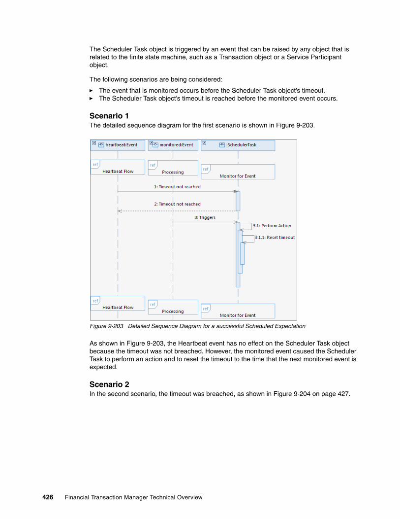
The Scheduler Task object is triggered by an event that can be raised by any object that is related to the finite state machine, such as a Transaction object or a Service Participant object.
The following scenarios are being considered:
� The event that is monitored occurs before the Scheduler Task object’s timeout.� The Scheduler Task object’s timeout is reached before the monitored event occurs.
Scenario 1The detailed sequence diagram for the first scenario is shown in Figure 9-203.
Figure 9-203 Detailed Sequence Diagram for a successful Scheduled Expectation
As shown in Figure 9-203, the Heartbeat event has no effect on the Scheduler Task object because the timeout was not breached. However, the monitored event caused the Scheduler Task to perform an action and to reset the timeout to the time that the next monitored event is expected.
Scenario 2In the second scenario, the timeout was breached, as shown in Figure 9-204 on page 427.
426 Financial Transaction Manager Technical Overview

Figure 9-204 Detailed Sequence Diagram for Scheduled Expectation with the timeout breached
As shown in Figure 9-204, the monitored event does not occur before the timeout. Therefore, the Heartbeat event triggers a state change of the Scheduler Task object to an alert state and notifies the operator. This action leads into the exception processing pattern, as described in 9.15, “Error handling and alerts patterning” on page 438.
9.13.4 Object lifecycle diagram
The Scheduler Task object is the only Financial Transaction Manager object that is identified in this pattern. However, the actions that are performed by the Scheduler Task object in response to its timeout being breached or the monitored event occurring affects other objects, such as deactivating or activating a Service Participant object and triggering state changes in a transactions lifecycle.
In the scenarios that were described in 9.13.1, “High-level description” on page 423, the only state change that occurs for the Scheduler Task object is when its timeout is breached. There is no state change when a monitored event is successfully processed. This can be seen in the Finite State Machine for the Scheduler Task object (for more information, see 9.13.5, “Finite State Machine” on page 428).
When a monitored event is not received when expected, a state change occurs and the object has a lifecycle, as shown in Figure 9-205 on page 428.
Chapter 9. Patterns 427

Figure 9-205 Object Lifecycle Diagram for a Scheduled Expectation with a breached timeout
In this example lifecycle, when the timeout is reached, the Scheduler Task moves to an alert state and the operator is notified. There are two ways to reset the Scheduler Task in this example: by an operator action or by the monitored event occurring.
The ability for an operator to reset the Scheduler Task should always be present; however, it might not be appropriate for the automatic reset of the timeout to occur when the next monitored event occurs. This depends on the nature of the action that is performed; for example, if the Scheduler task is performing a sequencing role, performing the action when the next monitored event occurs might cause transactions to be processed in the wrong sequence.
9.13.5 Finite State Machine
The Finite State Machine for a Scheduler Task varies depending on the role that this task is performing, the event that is monitored, and the action that is performed, as shown in Figure 9-206 on page 429.
428 Financial Transaction Manager Technical Overview

Figure 9-206 Example Finite State Machine for Scheduled Expectations
The Finite State Machine that is shown in Figure 9-206 acts on a Scheduler Task object that monitors for the reception of a valid physical transmission. The following process occurs:
1. If the physical transmission is received before the Scheduler Task’s timeout, the action A_ProcessPTArrive is started.
2. If heartbeat event E_Heartbeat detects that the timeout was breached, it causes a state change to S_WaitOverdue. This state is an alert state, as can be seen by the PMP_Alert stereotype.
3. The A_TimeoutNotify action is started, which raises an alert to the operator.
4. There are two possible resolutions in this example:
a. The operator can take an action to Verify the alert. This causes the A_PtTArrive action to occur, which resets the timeout and raises an event, E_SchedReset, to reset the state of the Scheduler Task to S_WaitPTReceive.
b. The overdue event occurs and causes the A_PtTArrive action to occur, which resets the timeout and raises an E_SchedReset event to reset the state of the Scheduler Task to S_WaitPTReceive.
Note: The E_HeartBeatStart event acts upon the Scheduler Task in both states, which causes the A_InitMonitor action to be started when WebSphere Message Broker starts and ensures that the Scheduler Task is correctly started.
Chapter 9. Patterns 429

9.13.6 Process highlights
This pattern is concerned with the monitoring of events that are raised by other Financial Transaction Manager processes and acting upon them when they are received.
The definition of a Scheduled Task within IBM Rational Software Architect is shown in Figure 9-207.
Figure 9-207 Definition of a Scheduler Task in Rational Software Architect
In this example, the entry in the Resource Ref field is used to link the Scheduler Task to another Financial Transaction Manager object. In this case, the object is a Service Participant; therefore, the Scheduler Task is linked to an interface.
The Scheduler Task also is linked to a Calendar Group, which is used to calculate the initial and subsequent timeouts.
For more information about the definition of Calendar Groups within Rational Software Architect, see 9.8.6, “Process highlights” on page 368.
9.13.7 Pattern interaction
This pattern interacts with the following schedule-based patterns:
� 9.12, “Scheduled activity pattern” on page 415� 9.14, “Heartbeats monitoring (scheduling) pattern” on page 431
In addition, this pattern can interact with any other patterns that raise events that might require to be monitored. For example, with the pattern that is described in 9.2, “Routing, IBM Operational Decision Manager rules, and multiple targets pattern” on page 282, monitor for particular routing events or Service Participant Finite State Machine events. Similarly, this pattern can be used to monitor for user actions or error events, as described in 9.15, “Error handling and alerts patterning” on page 438.
430 Financial Transaction Manager Technical Overview

9.14 Heartbeats monitoring (scheduling) pattern
This pattern describes two monitoring scenarios: one in which Financial Transaction Manager sends a periodic message (sometimes known as a technical heartbeat) to an external system to let that system know that Financial Transaction Manager is still running, and another scenario in which Financial Transaction Manager waits for a periodic message from another system to indicate the system is still running. Because these scenarios rely on existing patterns that were described in this chapter, for the purposes of this pattern, the first scenario is known as the “Scheduled Activity monitoring” scenario and the second scenario is known as the “Scheduled Expectation monitoring” scenario.
Figure 9-208 shows the use case for the Scheduled Activity monitoring scenario.
Figure 9-208 Scheduled Activity monitoring scenario
Figure 9-209 shows the use case for the Scheduled Expectation monitoring scenario.
Figure 9-209 Scheduled Expectation monitoring scenario
Chapter 9. Patterns 431

9.14.1 High-level description
Figure 9-210 shows the High-level Sequence diagram for the Scheduled Activity monitoring scenario.
Figure 9-210 High-level Sequence diagram for the Scheduled Activity monitoring scenario
Figure 9-211 shows the High-level Sequence diagram for the Scheduled Expectation monitoring scenario.
Figure 9-211 High-level Sequence diagram for the Scheduled Expectation monitoring scenario
432 Financial Transaction Manager Technical Overview
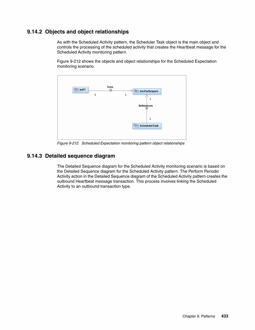
9.14.2 Objects and object relationships
As with the Scheduled Activity pattern, the Scheduler Task object is the main object and controls the processing of the scheduled activity that creates the Heartbeat message for the Scheduled Activity monitoring pattern.
Figure 9-212 shows the objects and object relationships for the Scheduled Expectation monitoring scenario.
Figure 9-212 Scheduled Expectation monitoring pattern object relationships
9.14.3 Detailed sequence diagram
The Detailed Sequence diagram for the Scheduled Activity monitoring scenario is based on the Detailed Sequence diagram for the Scheduled Activity pattern. The Perform Periodic Activity action in the Detailed Sequence diagram of the Scheduled Activity pattern creates the outbound Heartbeat message transaction. This process involves linking the Scheduled Activity to an outbound transaction type.
Chapter 9. Patterns 433

Figure 9-213 shows the Detailed Sequence diagram for the Scheduled Activity monitoring scenario.
Figure 9-213 Scheduled Activity monitoring scenario Detailed Sequence diagram
434 Financial Transaction Manager Technical Overview
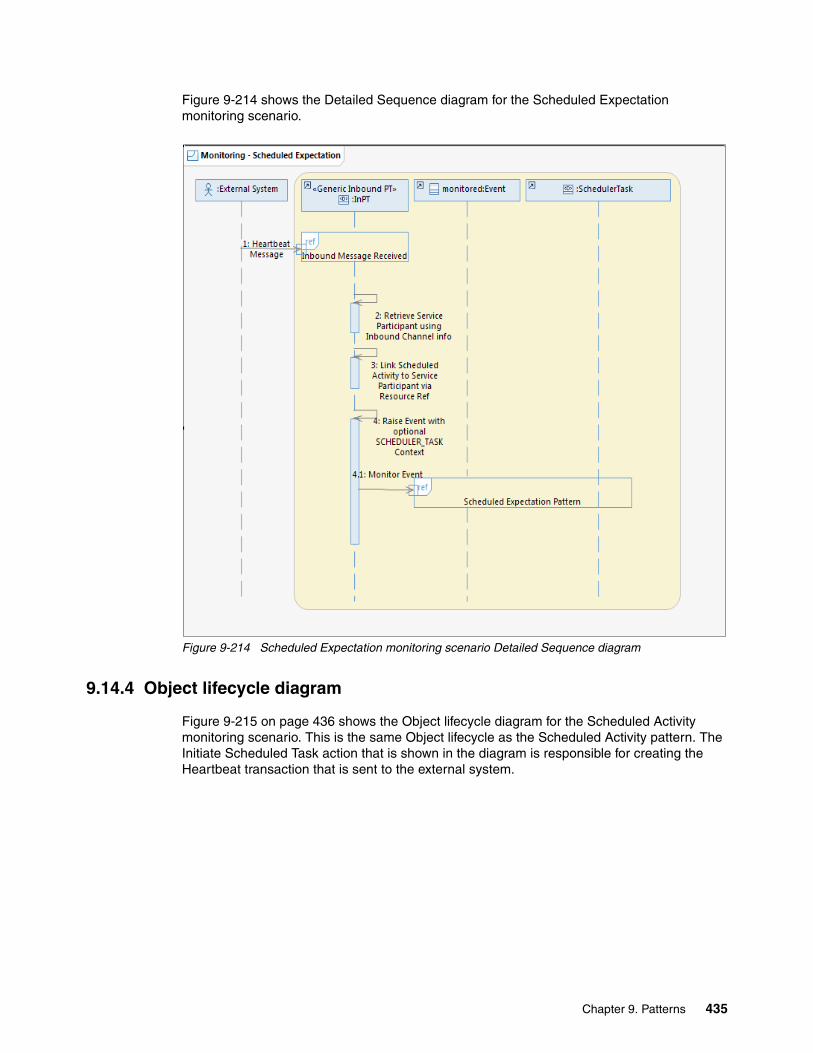
Figure 9-214 shows the Detailed Sequence diagram for the Scheduled Expectation monitoring scenario.
Figure 9-214 Scheduled Expectation monitoring scenario Detailed Sequence diagram
9.14.4 Object lifecycle diagram
Figure 9-215 on page 436 shows the Object lifecycle diagram for the Scheduled Activity monitoring scenario. This is the same Object lifecycle as the Scheduled Activity pattern. The Initiate Scheduled Task action that is shown in the diagram is responsible for creating the Heartbeat transaction that is sent to the external system.
Chapter 9. Patterns 435

Figure 9-215 Scheduled Activity monitoring Object lifecycle diagram
Figure 9-216 shows the Object lifecycle diagram for the Scheduled Expectation monitoring scenario. This is the same Object lifecycle diagram as the Scheduled Expectation pattern. The monitored event is triggered by the incoming Heartbeat message and, if it is not received, the timeout reached event triggers the notification to the operator that the external system is offline.
Figure 9-216 Scheduled Expectation monitoring Object lifecycle diagram
9.14.5 Finite State Machine
Figure 9-217 on page 437 shows a typical Finite State Machine diagram for the Scheduled Activity monitoring scenario. This is the same Finite State Machine diagram as the Schedule Activity pattern. The A_ProcessSchedulerActivity action that is shown in the diagram is responsible for creating the Heartbeat transaction that is sent to the external system.
436 Financial Transaction Manager Technical Overview

Figure 9-217 Scheduled Activity monitoring Finite State Machine
Figure 9-218 shows a Finite State Machine diagram that can be used to model the Scheduled Expectation monitoring scenario. This Finite State Machine diagram was used in the Scheduled Expectation pattern. The E_TransPTValid event is generated by the inbound Heartbeat message that is received by the external system. The A_ProcessPTArrive action is responsible for resetting the timeout the Schedule Task object.
Figure 9-218 Scheduled Expectation monitoring Finite State Machine
Chapter 9. Patterns 437

9.14.6 Process highlights
For the Scheduled Activity monitoring scenario, a typical process is to create a Scheduler Task to represent the scheduled activity processing of sending the periodic heartbeat message. This is modelled in Rational Software Architect by using Calendar Groups and Schedule Entry entries and imported into the Financial Transaction Manager database. A Finite State Machine is created to model the process of the Scheduler Task, with an E_HeartbeatStart transition to start an action that sets up the next timeout for the Scheduler Task by using the Schedule Entry and Calendar Group information that is linked to the Scheduler Task. Another transition that is based on the E_Heartbeat event is needed to trigger when the Scheduler Task times out. This starts an action that creates an outbound Heartbeat transaction, and the action raises an E_TxnOutCreated event by using the subtype as context. This gets picked up per the Outbound Message or File pattern and the periodic transmission is sent to the external system to indicate that Financial Transaction Manager is still active.
For the Scheduled Expectation monitoring scenario, the initiator is an inbound Heartbeat transmission from an external system. The message is received on a Financial Transaction Manager inbound channel and an action is started to resolve the interface to a Scheduler Task. This is done by using the inbound channel details to retrieve the Service Participant that is associated with the interface. The Scheduler Task that is associated with the Service Participant can be retrieved through the RESOURCE_REF field of the Scheduler Task. As before, the Scheduler Task is modelled in advance of this in Rational Software Architect and a Finite State Machine is created to model the process of the Scheduler Task that is waiting to transition on an event that is caused by the incoming Heartbeat message that is arriving (for example, E_TransPTValid in the Finite State Machine of the Scheduled Expectation pattern). After this event is received and the transition triggered, the timeout value of the Scheduler Task is updated. If a Heartbeat message is not received from the external system before the next timeout, an error scenario is triggered.
9.14.7 Pattern interaction
The Scheduled Activity and Scheduled Expectation patterns are integral to this pattern. This pattern also interacts with the Outbound Message or File pattern when the Heartbeat Message is sent to the external system as part of the Scheduled Activity monitoring scenario. The Scheduled Expectation monitoring scenario interacts with the Error handling and alerts pattern when a Heartbeat message from an external was not received on time. This alerts the operator of the timeout and possibly log an error in the Financial Transaction Manager database.
9.15 Error handling and alerts patterning
This pattern addresses ways of investigating and resolving alerts and errors that can occur during transaction processing within Financial Transaction Manager. The following main types of errors can occur:
� Technical issues that cause the processing to stop or enter an alert state; for example, mapping and unparseable data.
� Processing issues that arise because of design and are expected in certain circumstances; for example, business validation failure or output destination that cannot be found.
438 Financial Transaction Manager Technical Overview

In both cases, Financial Transaction Manager can notify an operator that an issue that occurred and allow them to investigate and resolve the issue. For more information about the resolution of the issue from within the Financial Transaction Manager Operation and Administration Console, see 6.3.5, “Resolving alerts and operator actions” on page 188.
This pattern focuses on the alerts and issues that are raised as part of the processing flow. The use case for this pattern is shown in Figure 9-219.
Figure 9-219 Use case for error handling and alerts pattern
9.15.1 High-level description
When a transaction that is processed within Financial Transaction Manager encounters an error, an alert is raised and the operator notified. In addition, an event can be emitted to be sent to a monitoring system, such as IBM Business Monitor, as shown in Figure 9-220 on page 440.
Chapter 9. Patterns 439

Figure 9-220 High-level interaction diagram for alert and errors
At a high level, this process is the same for technical and processing errors. In Figure 9-220, the following process is shown:
1. A transaction or physical transmission encounters an issue while it is processed; for example, a mapping error or business validation.
2. The action that is processing the transaction or physical transmission issues an event that moves the object to a state that is defined as an alert state.
3. This event also causes an action to be triggered, which causes an alert to be emitted to an external monitoring application. The emitted event can be enriched with more detail, if required.
4. This action also notifies the operator that an alert occurred.
5. The operator investigates the cause of the error by using the Financial Transaction Manager Operation and Administration Console.
6. After the investigation his complete, the operator resolves the transaction issue by taking an action within the Financial Transaction Manager Operation and Administration Console. For more information, see 6.3.5, “Resolving alerts and operator actions” on page 188.
440 Financial Transaction Manager Technical Overview

7. When a user takes an action, an event is raised that controls the state that the object is moved to; for example, a Cancel resolution might cause the transaction to be placed in a cancelled end state or a Resubmit might cause the transaction to be placed back in the process flow.
9.15.2 Objects and object relationships
The Financial Transaction Manager Objects that are identified in this pattern for transactions that enter an alert state are shown in Figure 9-221.
Figure 9-221 Alerts and Errors: Object/Object Relationships
When a Financial Transaction Manager object enters an alert state, it can raise alerts that are sent to external systems or to the operator. The operator can then take an action on the affected object from within the Financial Transaction Manager OAC, which triggers further processing; for example, cancelling the transaction or resubmitting it.
9.15.3 Detailed sequence diagram
The detailed sequence diagram describes the interaction between the objects within the pattern. The following use cases were identified:
� A transaction encounters an error and the operator cancels it.� Transmission or transaction encounters an error and the operator resubmits it.
These processes are similar with the exception that the first use case puts the transaction in an end state and no further processing is carried out on it.
The detailed sequence diagram is shown in Figure 9-222 on page 442.
Chapter 9. Patterns 441

Figure 9-222 Detailed Sequence Diagram: Transaction Failure
A batch object often is validated after the transactions within it are validated. The detailed sequence diagram for a batch that encounters and error is shown in Figure 9-223 on page 443.
442 Financial Transaction Manager Technical Overview

Figure 9-223 Detailed Sequence Diagram: Batch Failure and Cancel
In this example, the operator cancelled the failed batch, which causes the transactions within the batch and the physical transmission to be updated and moved to an alert state.
The detailed sequence diagram for a batch that encounters a failure and then is released (the reason for the issue was resolved) is shown in Figure 9-224 on page 444.
Chapter 9. Patterns 443

Figure 9-224 Detailed Sequence Diagram - Batch Failure and Release
In this example, the processing of releasing the batch allows the transactions that is contained within it to continue processing.
Physical transmissions often encounter errors before the creation of the subsequent batch or transaction objects. Figure 9-225 on page 445 shows a detailed sequence diagram for a physical transmission that encounters an error.
444 Financial Transaction Manager Technical Overview

Figure 9-225 Detailed Sequence Diagram - Physical Transmission Failure
In this example, a physical transmission encountered an error (for example, a mapping or syntax validation error) and raises an alert.
A user investigates and resolves the problem (for example, by correcting mapping parameters or maps) and resubmits the physical transmission for processing or cancels the transmission.
9.15.4 Object lifecycle diagrams
The lifecycle of the objects for this pattern follows the same generic lifecycle in that the following process occurs:
1. An object encounters an error.
2. An alert is raised and the operator is notified.
3. The operator investigates the cause of the alert and take one of the following actions:
a. The operator cannot resolve the issue and cancels the alert.
b. The operator resolves the cause of the issue and resubmits the object back into the process flow at the point the issue occurred; for example, to revalidate.
c. The operator cannot resolve the cause of the issue, but the object can be processed further. The operator can release the object back into the process flow after the point that the issue occurred.
In this section, we use the example of a transaction failing a validation. The object lifecycle diagram is shown in Figure 9-226 on page 446.
Chapter 9. Patterns 445

Figure 9-226 Object lifecycle for an object entering an alert state
In this example, the following process occurs:
1. A transaction fails validation and moves into an alert state of Awaiting Repair.
2. At the same time, the Notify Operator action creates and sends an alert to an external monitoring application and to the operator.
3. The operator logs into the Financial Transaction Manager Operation and Administration Console and works with the transactions that have a state of Awaiting Repair.
4. The operator investigates the reasons why the transaction failed validation and then can perform one of the following tasks:
a. Cancel the transaction and move it to a cancelled end state.
b. Resubmit the transaction to be revalidated; for example, validation failed because of incorrectly set up data that was corrected.
c. Release the transaction for further processing as the validation failure is incorrect or not appropriate for this transaction..
When a batch encounters an error, the object lifecycle of the transactions are affected, as shown in Figure 9-227 on page 447.
446 Financial Transaction Manager Technical Overview

Figure 9-227 Object lifecycle for a transaction entering an alert state due to batch error
9.15.5 Finite State Machine
The Finite State Machines in this pattern define the process flow to be followed when an error occurs and the attributes of the states. The state definitions contain the alert behavior and the allowed actions on those states.
Figure 9-228 shows part of a Finite State Machine for a physical transmission.
Figure 9-228 Example of a finite state machine for a physical transmission
Chapter 9. Patterns 447

This snippet of a Finite State Machine for an incoming physical transmission shows the validation section with two events being raised when an error occurs, E_MpInMappingAborted and E_PtValFail. These events trigger the action A_NotifyOps. This action causes an alert to be raised and the physical transmission moves to one of the two alert states, S_InPTMapFailed or S_PTValidationFail.
It also shows the constraints that were added to these states. These constraints are available in the Operations and Administration Console as user actions for objects in this state.
Both of these states are configured as alert states by adding the PMP_Alert stereotype to the state properties, as shown in Figure 9-229.
Figure 9-229 Finite State Machine: State Stereotypes Properties
Note: The PMP_Alert stereotype is used to identify alert states. The PMP_OpsControl stereotype is used to identify states that are not alerts, but require user intervention.
448 Financial Transaction Manager Technical Overview
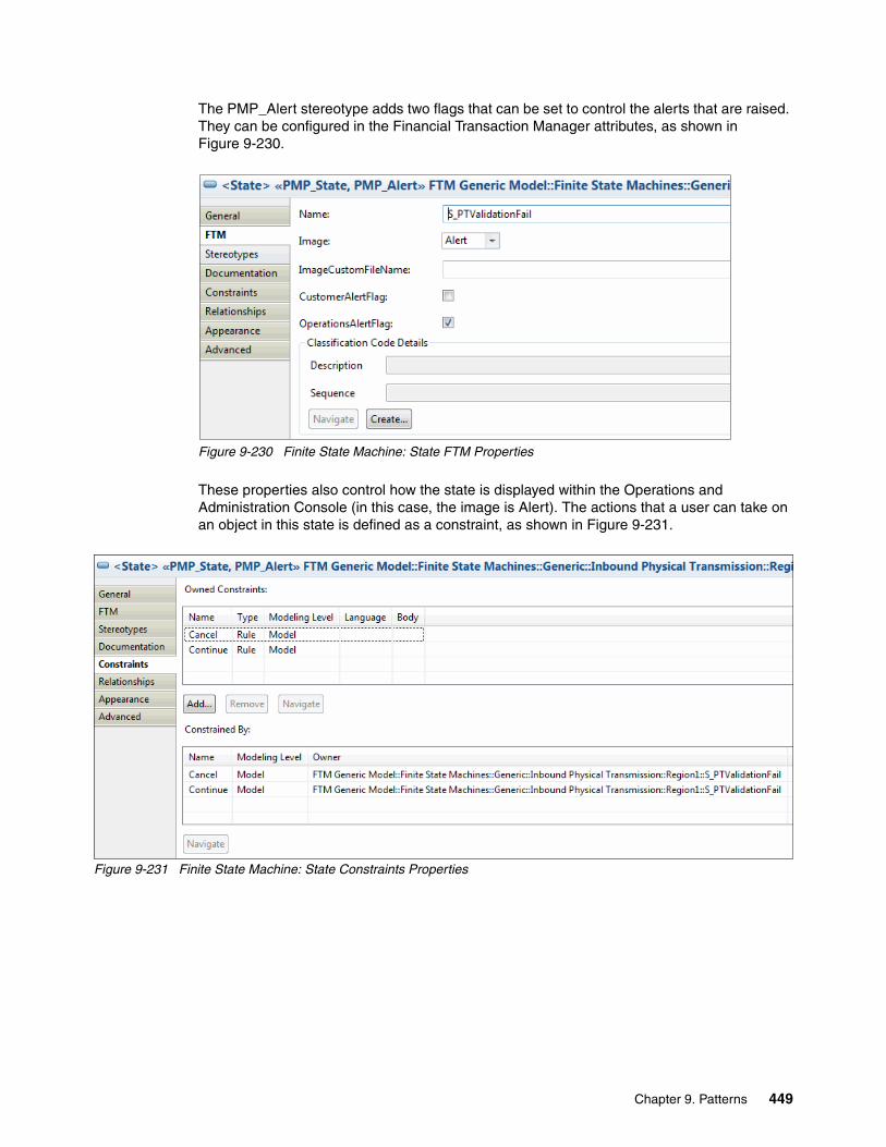
The PMP_Alert stereotype adds two flags that can be set to control the alerts that are raised. They can be configured in the Financial Transaction Manager attributes, as shown in Figure 9-230.
Figure 9-230 Finite State Machine: State FTM Properties
These properties also control how the state is displayed within the Operations and Administration Console (in this case, the image is Alert). The actions that a user can take on an object in this state is defined as a constraint, as shown in Figure 9-231.
Figure 9-231 Finite State Machine: State Constraints Properties
Chapter 9. Patterns 449

In this example, only the Cancel or Continue options are available. An example of a Finite State Machine for a transaction is shown in Figure 9-232.
Figure 9-232 Example of a Finite State Machine for a transaction
This example shows a Finite State Machine for a transaction. The S_WaitingForRepair state is defined as an alert state by adding the PMP_Alert stereotype to it. It also has two possible actions that can be taken (Cancel and Resubmit) both of which are defined as Constraints in the state properties.
9.15.6 Process highlights
In any process, there are points where issues can arise and it is important to understand what those errors are and how they can be resolved. There are several types of issues that can arise, from purely technical issues (for example, receiving unparseable data) that require resolution outside of Financial Transaction Manager, to business issues that can be resolved within it. When a Finite State Machine is built, it is important to build into the design error handling and resolution.
450 Financial Transaction Manager Technical Overview

The actions that a user can take within the Operation and Administration Console are defined against the state in Rational Software Architect. However, a Financial Transaction Manager action subflow also must be created to process the operator command and to raise the event that causes the object to change state. In addition, errors and alerts might arise from the use of applications, such as WebSphere Transformation Extender or Operational Decision Manager.
WebSphere Transformation Extender issues are likely to be mapping failures. These can be handled in the same way as described for a physical transmission, with the user canceling or resubmitting to run the mapping again.
Operational Decision Manager can raise various issues, including validation errors or routing target not being found. In both cases, the transaction should be moved to an alert state to allow a user to resubmit the transaction to call out to Operational Decision Manager to cancel the transaction or to release the message to continue processing without the data from the rules.
9.15.7 Pattern interaction
This pattern can interact with all other patterns that might encounter an issue.
Chapter 9. Patterns 451

452 Financial Transaction Manager Technical Overview

Related publications
The publications that are listed in this section are considered particularly suitable for a more detailed discussion of the topics that are covered in this book.
IBM Redbooks
The following IBM Redbooks publications provide more information about the topics in this document. Some publications that are referenced in this list might be available in softcopy only:
� DB2 UDB for z/OS: Design Guidelines for High Performance and Availability, SG24-7134
� Patterns: Extended Enterprise SOA and Web Services, SG24-7135
� DB2 9 for z/OS Performance Topics, SG24-7473
� Rational Application Developer for WebSphere Software V8 Programming Guide, SG24-7835
� High Availability in WebSphere Messaging Solutions, SG24-7839
� IBM WebSphere Application Server V8 Concepts, Planning, and Design Guide, SG24-7957
You can search for, view, download, or order these documents and other Redbooks, Redpapers, Web Docs, draft, and additional materials, at the following website:
Finite State Machineibm.com/redbooks
Online resources
The following websites also are relevant as further information sources:
� IBM Financial Transaction Manager Information Center:
http://www.ibm.com/support/docview.wss?uid=swg27038668
� IBM DB2 Database for Linux, UNIX, and Windows Information Center:
http://pic.dhe.ibm.com/infocenter/db2luw/v9r7/index.jsp
Help from IBM
IBM Support and downloads
http://www.ibm.com/support
IBM Global Services
http://www.ibm.com/services
© Copyright IBM Corp. 2014. All rights reserved. 453

454 Financial Transaction Manager Technical Overview
(1.0” spine)0.875”<
->1.498”
460 <->
788 pages
Financial Transaction Manager Technical Overview
Financial Transaction Manager
Technical Overview
Financial Transaction Manager
Technical Overview
Financial Transaction Manager Technical Overview

Financial Transaction Manager
Technical Overview
Financial Transaction Manager
Technical Overview

®
SG24-8187-00 ISBN 0738439118
INTERNATIONAL TECHNICALSUPPORTORGANIZATION
BUILDING TECHNICAL INFORMATION BASED ON PRACTICAL EXPERIENCE
IBM Redbooks are developed by the IBM International Technical Support Organization. Experts from IBM, Customers and Partners from around the world create timely technical information based on realistic scenarios. Specific recommendations are provided to help you implement IT solutions more effectively in your environment.
For more information:ibm.com/redbooks
®
Financial Transaction Manager Technical Overview
Understand how a Financial Transaction Manager solution works
Create reusable patterns to accelerate development
Learn by example with practical scenarios
Dramatic forces of change continue to sweep the financial services industry. The age of the empowered customer is here and are changing the way financial products are delivered, sold, and serviced, which are making relationships more complex than ever. The explosion of data and intense competition, which is combined with slow or inconsistent economic conditions, makes it imperative for financial institutions to find new and cost effective ways to increase market share, renew customer trust, and drive profitable growth.
In this new business environment, the transaction processing arm of the industry is facing increased pressure to reduce float, better manage liquidity, and provide regulators and clients with increased transparency. At the same time, the industry must effectively manage the risks that are associated with introducing customer-focused and regionalized products and services.
Financial Transaction Manager enables the management, orchestration, and monitoring of financial transactions during their processing lifecycle. Financial Transaction Manager provides the capability to integrate and unify financial transactions in various industry formats (including ISO 20022, SWIFT, NACHA, EDIFACT, ANSI X12 and others). By using Financial Transaction Manager, financial institutions gain visibility into message processing, balance financial risk, and facilitate effective performance management.
This IBM Redbooks publication outlines how Financial Transaction Manager is deployed to realize the benefits of transaction transparency, increase business agility, and allow for innovation that is built on a robust and high-performance environment.
Back cover