
Final report on ntpc faridabad
37
An Industrial Training Report On NTPC Faridabad Submitted in Partial Fulfillment of the Requirements for the Degree of Bachelor of Technology In Electrical Engineering By PAWAN AGRAWAL Roll No. 1104320028 Department of Electrical Engineering Bundelkhand Institute of Engineering & Technology (An Autonomous Institute) Jhansi (U.P.) India - 284128 i
-
Upload
pawan-agrawal -
Category
Education
-
view
120 -
download
6
Transcript of Final report on ntpc faridabad

An
Industrial Training Report
On
NTPC Faridabad
Submitted in Partial Fulfillment of the
Requirements for the Degree of
Bachelor of Technology
In
Electrical Engineering
By
PAWAN AGRAWAL
Roll No. 1104320028
Department of Electrical Engineering
Bundelkhand Institute of Engineering & Technology
(An Autonomous Institute)
Jhansi (U.P.) India - 284128
i

ACKNOWLEDGMENT
I am very grateful to all those who helped me towards its smooth and efficient
completion & under whose guidance this summer training was conducted successfully. I
feel highly indebted to all the senior NTPC officials who extended me a constructive
help in the technical field.
I feel especially thankful to
Mr. K.K. Sharma (Sr. Manager-Chemistry)
Mrs. Prachi (Electrical Maintenance)
Mr. N.N. Mishra (AGM- O&M)
Mr. Manoj Agarwal (DGM-Mechanical Maintenance)
Mr. Jimmy Joseph (S.S. - C&I)
Mr. D.C. Tiwari (S.S. - Operation & Fuel handling)
I gratefully acknowledge all the engineers/staff who gave us their valuable time,
encouragement & constructive criticism for familiarising us with all technical aspects of
the power plant.
PAWAN AGRAWAL
B.Tech Final year
Electrical Engineering
Roll no. 1104320028
ii

CONTENTS
Cover Page i
Acknowledgement ii
Certificate iii
Contents iv
List of Figures vi
List of Tables vii
1. About The Company 1
2. Introduction to NTPC Faridabad 3
2.1 Location 3
2.2 Major Milestones 3
2.3 Installed capacity 4
2.4 Production Inputs 4
2.5 Requirements 4
2.6 Anti-Salient Features 4
3. Basic Working of the Plant 5
4. Fuels 6
4.1 Natural Gas 6
4.2 Naphtha 7
5. Mechanical Systems 8
5.1 Gas Turbine 8
5.2 WHRSG 10
5.3 Steam Turbine 12
6. Switchyard 15
6.1 Circuit Breaker 15
6.2 Lightening Arrester 15
6.3 Earthing Switch 16
6.4 Bus Bar 17
6.5 Capacitor Voltage Transformer 17
6.6 Wave Trap 18
iv

6.7 PLCC 18
6.8 Current Transformer 19
6.9 Isolator 19
7. Generator 20
7.1 Main Components 20
7.2 Excitation system 21
7.3 Generator protection 21
7.4 Generator cooling system 22
7.5 Cooling specifications of turbo-generators 22
8. Transformers 23
8.1 Transformer accessories 23
8.2 Cooling of transformers 24
8.3 Main transformers 25
9. DC system 26
9.1 Requirement of DC system 26
9.2 Description of battery 26
9.2 Battery Charger 27
10. Switchgear 27
10.1 L.T. switchgear 27
10.2 H.T. switchgear 27
10.3 Variable Frequency Drive 28
10.4 Two channel arrangement for synchronous motor 29
11. Conclusion 30
References 31
V

LIST OF FIGURES Page No.
Fig 1.1 NTPC generation growth 2
Fig 1.2 NTPC in power sector 2
Fig 2.1 Plant Overview 3
Fig 2.2 Plant Layout 4
Fig 3.1 Combined Cycle Power Generation 5
Fig 4.1 Pipelines of gas source 6
Fig 4.2 Naphtha Specifications 7
Fig 5.1 Working of WHRSG 11
Fig 6.1 Lightening Arrester 16
Fig 6.2 Capacitor Voltage Transformer 17
Fig 6.3 Wave Trap 18
Fig 6.4 Current Transformer 19
Fig 6.5 Isolators 19
Fig 8.1 Three-Phase Transformers 25
Fig 10.1 Electrical scheme of VFD 28
Fig 10.2 Two channel arrangement of synchronous motor 29
vi

LIST OF TABLES Page No.
Table 5.1 Gas Turbine Specifications 9
Table 5.2 Gas Turbine Generator Specifications 9
Table 5.3 WHRSG Specifications 12
Table 5.4 Specifications of HP Turbine 13
Table 5.5 Specifications of LP Turbine 13
Table 5.6 Steam Turbine Generator Specifications 14
Table 6.1 Specifications of earthing switch 17
Table 7.1 Generator Specifications 21
vii

1. ABOUT THE COMPANY
Corporate Vision:
“A world class integrated power major, powering India’s growth, with increasing global
presence”
Core Values: (BE COMMITTED)
B-Business Ethics
E- Environmentally & Economically Sustainable
C-Customer Focus
O-Organizational Pride
M-Mutual Respect & Trust
M-Motivating Self & Others
I-Innovation & Speed
T-Total Quality For Excellence
T-Transparent & Respected Organization
E-Enterprising
D-Devoted
NTPC Limited is the largest thermal power generating company of India. A public
sector company, it was incorporated in the year 1975 to accelerate power development
in the country as a wholly owned company of the Government of India. At present,
Government of India holds 89.5% of the total equity shares of the company and the
balance 10.5% is held by FIIs, Domestic Banks, Public and others. Within a span of 31
years, NTPC has emerged as a truly national power company, with power generating
facilities in all the major regions of the country. NTPC’s core business is engineering,
construction and operation of power generating plants. It also provides consultancy in
the area of power plant constructions and power generation to companies in India and
abroad.
1

As on date the installed capacity of NTPC is 43,582 MW through its 17 coal based
(31,445 MW), 7 gas based (3,955 MW), 3 Hydro based (1,328 MW) and 7 Joint Venture
Projects (5,754 MW).
NTPC’s share on 31 Mar 2007 in the total installed capacity of the country was 20.18%
and it contributed 28.50% of the total power generation of the country during 2006-07.
Fig 1.1 NTPC Generation Growth
Fig 1.2 NTPC in power sector
2

2. INTRODUCTION TO NTPC FARIDABAD
2.1 Location
Located near village Mujedi & Neemka in Faridabad district of Haryana State.
2.2 Major Milestones
Ever since then honorable Prime Minister Sh. I.K. Gujral laid down the foundation
stone on 03rd august 1997.
First two units of 138MW were commissioned on 21st Jan 2000 and 22nd March, 2000
and one unit of 156MW was commissioned on 16th July 2001 by Haryana Vidyut
Prasaran Nigam.
Faridabad project was taken over by NTPC from HVPN on 13th Feb, 2002.
It is the only power plant in this country to supply its entire power to a state i.e.
Haryana rather than to the national grid.
Fig 2.1 Plant Overview
2.3 Installed Capacity
Stage I (GT) = 2 X 138 MW
Stage II (ST) = 1 X 156 MW
3
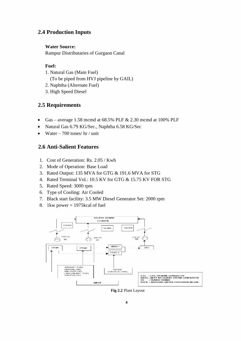
2.4 Production Inputs
Water Source:
Rampur Distributaries of Gurgaon Canal
Fuel:
1. Natural Gas (Main Fuel)
(To be piped from HVJ pipeline by GAIL)
2. Naphtha (Alternate Fuel)
3. High Speed Diesel
2.5 Requirements
Gas – average 1.58 mcmd at 68.5% PLF & 2.30 mcmd at 100% PLF
Natural Gas 6.79 KG/Sec., Naphtha 6.58 KG/Sec
Water – 700 tones/ hr / unit
2.6 Anti-Salient Features
1. Cost of Generation: Rs. 2.05 / Kwh
2. Mode of Operation: Base Load
3. Rated Output: 135 MVA for GTG & 191.6 MVA for STG
4. Rated Terminal Vol.: 10.5 KV for GTG & 15.75 KV FOR STG
5. Rated Speed: 3000 rpm
6. Type of Cooling: Air Cooled
7. Black start facility: 3.5 MW Diesel Generator Set: 2000 rpm
8. 1kw power = 1975kcal of fuel
Fig 2.2 Plant Layout
4

3. BASIC WORKING OF THE PLANT
(Combined Cycle Power Generation)
1. The fuel is fed in the two turbines.
2. The fuel is burnt in the gas turbines to release the flue gases at high pressure and
temperature. These gases rotate the turbine shaft.
3. The shaft of the turbine is linked to the shaft of the gas turbine generator which leads
to the production of energy at the two generators.
4. The flue gases produced are passed through waste heat recovery steam generators
where it passes from super-heaters, evaporators, economizers and condensate
preheated.
5. Water present and flowing in the above devices absorb heat from the hot flue gases
and get converted in to high pressure and low pressure steam.
6. The high pressure steam generated in the WHRSG is passed to the steam turbine and
the low pressure steam to LP turbine.
7. The steam available at the outlet of HP turbine and LP turbine generated in the
WHRSG are supplied to the LP turbine.
8. In the step 6 & 7 the steam supplied to the HP and LP turbines rotates the respective
turbine.
9. These rotors are connected to the rotor of the steam turbine generators by rigid
coupling. Therefore due to the rotation of the turbine rotor of the steam turbine
generators by rigid coupling. Therefore due to rotation of the turbine rotor, the
generator turbine also rotates thereby producing electricity at the generator.
Hence in 9 steps 432 MW of electricity is produced.
Fig 3.1 Combined Cycle Power Generation
5

4. FUELS
Gas turbines are capable of burning a range of fuels including Naphtha, crude oil and
natural gas. Selection of fuel depend upon several factors including availability of fuel,
fuel cost cleanliness of the fuel. Natural gas is an ideal fuel because it provides
efficiency and reliability with low operation and maintenance cost. Liquid fuels
particularly heavy oils; usually contain contaminants, which case corrosion and fouling
in gas turbine. Contaminants which cannot be removed from fuel, may leave deposits
in gas turbine, which reduces the performance and adds to the maintenance cost.
Duel fuel system is commonly used, enabling the gas turbine to burn up the fuels when
primary fuel sources are not available. Duel fuel system can be designed to fire both
fuels simultaneously.
4.1. Natural gas
Natural gas is an ideal fuel for se in gas turbine. It contains primarily Methane (CH4)
other gases are ethane (C2H6), Nitrogen (N2), Carbon dioxide (CO2) and Sulphur(S). It
has following advantages:
Clean burning.
Availability at lower cost.
Particularly free from solid residue.
High calorific value of Methane.
Low Sulphur content.
For FGPP, This gas comes from Bombay High through medium of pipelines and one
pipeline from Village Chhainsa (Faridabad).
Fig 4.1 Pipelines of gas source
6
4.2. Naphtha
FGPP works on natural gas but if there is shortage of natural gas then plant is to be run
on Naphtha. Naphtha as compared to natural gas has less calorific value but there is no
alternate fuel other than Naphtha. It is cheaper than any other fuel and the amount of
flue gases that comes out of the Naphtha can also be sent out to boiler to boil the water
for manufacturing of steam for running the steam turbine.
Naphtha is highly inflammable and highly explosive fuel. When it makes a mixture
with air, it forms a very highly dangerous explosive mixture. When the supply of
natural gas cuts off, the pipelines are filled with air. So while using Naphtha, it is
necessary to remove that air because it can make explosive mixture with Naphtha. So
for flushing this air a high-speed diesel (HSD) is sent to the pipeline, which removes
the air present. In this way HSD enters the combustion chamber and working
continues. This is the procedure for working of gas turbine when it has to feed on
Naphtha without stopping the while plant, which was previously feed on natural gas.
Naphtha before entering the pipelines undergoes filtration various times so that there
should not be any impurity in that when it enters the combustion chamber. The main
difference between Naphtha and Natural gas is that, natural gas enters the combustion
chamber in the form of gas but Naphtha enters in form of liquid spray. Then it is
compressed in it and due to high compression it burns and leaves very highly
pressurized flue gases, which in turn is used to rotate the gas turbine. This entire
process of using the Naphtha as a fuel is known as Naphtha firing.
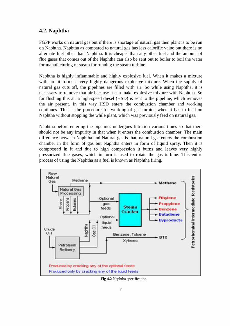
Fig 4.2 Naphtha specification
7

5. MECHANICAL SYSTEMS
The main generating unit consists of three main equipments in the plant. They are:
1. Gas Turbine
2. Waste Heat Recovery Steam Generator
3. Steam Turbine
5.1. Gas Turbine
It is a single shaft (with line compressive unit). It is a 50 Hz; 135MW machine which
runs on natural gas could also be operated on the liquid Naphtha. The gas turbine is
very heavy, industrial type, within line compressor multistage flow type. The
combustion chamber is of annular type.
According to the flow of the air compressor is placed first, combustion chamber is next
to it and turbine at the end of gas turbine. Two bearings are placed to support the shaft
of the machine, these turbines are provided at the compressor starting end, and other
are placed at the turbine end. The shaft of the unit is provided with the blades in the
turbine region.
5.1.1. Basic parts of the Gas Turbine:
1. Compressor: Is a fuel stage axial type. It is provided with a variable inlet guide
system to enable efficient operation. Filters are provided at the top of the
compressor to filter any unwanted material from entering the turbine. In the
compressor region there are 16 stages of blade, one set of blade, one set of blade
on shaft and other set of fixed blade comes alternatively.
2. Combustion chamber: There are two chambers in the gas turbine, one on each side
of the shaft, connected vertically and parallel to each other. The combustion
chambers are cylindrical in shape and attached to the unit in between the
compressor and turbine.
3. Turbine: It is provided at the end of the gas turbine unit. It consists of four stages
of blades it also has the gearing to support the shaft at its end.
Exhaust of the turbine is connected to the bypass stake which is further connected
to WHRSG. The bypass is take is provided with two gates namely diverter
damper and gelatin gates.
5.1.2. Working of the gas turbine:
During the start-up of generator, it act as motor. The generator is given supply and
compressor start working. The function of the compressor is to provide air at the high
pressure to combustion chamber, once air is supplied to the combustion fuel is
ignited. 8

Due to the burning of the fuel flue gases are released at high pressure and
temperature and thermal expansion of the gases rotates the turbine blades that are
connected to the shaft back supply to the generator is then stopped. Fuel supply is
slowly increased till the optimum speed (3000 rpm) is attained. Fuel supply is kept
constant. The fuel gases after rotating the turbine can be directed to the WHRSG sing
diverter damper and gelatin gate.
5.1.3. Gas Turbine Specifications:
manufacture SEIMENS(Germany); model-V 94.2
capacity 137.76 MW
compressor 16 stage
turbine 4 stages
burner Hybrid dual fuel
combustors SILO type
Air intake filters Pulse cleaning(576 in numbers)
By pass take Vertical 70 m in height
Ambient temperature 27 deg c
Ambient pressure 1013 Mbar
Table 5.1 Gas Turbine Specifications
5.1.4. Gas turbine generator specifications:
Relative humidity 60%
Voltage rating 10.5 kv
Power factor 0.85 lagging
KVA 170.12 MVA
Excitation current 833 Amp
Excitation voltage 410 V
Insulation type Class F micalastic
Connection type AA
Table 5.2 Gas turbine generator specifications
9

5.2. Waste Heat Recovery Steam Generator
The waste heat generator are unfired, heat recovery type design to accept the maximum
exhaust temperature along with flue gas flow from the turbine. It is a natural circulation
dual unit. All heat transfer surface are of fin type. The feed control system is located in
between the economizer and drain to eliminate the possibility of streaming in the
economizer and to enable operation with zero approach point thereby increasing in the
efficiency of the combine cycle plant. A condensate preheated is added to low
temperature zone of WHRB. There are two types of steam produced in this unit (H.P &
L.P).
5.2.1. Basic Parts of WHRSG:
1. Condensate Preheater: it is present at the end of WHRSG. It is added to lower
the temperature of flue gases in addition to increase the thermal efficiency of the
plant. It is consist of spiral fined tubes welded to the top and bottom headers. There
are maximum rows per module.
2. Economizers: There are three different types of economizers. These are:
a) L.P economizer: these tubes act as the economizer of the L.P steam; these are
spiral fined tubes welded to the top and bottom headers and have fully drainable
design.
b) H.P economizer: these tube act as economizer for H.P steam, they also have
spiral fined tubes welded to the top bottom headers and have fully drainable
design.
3. Evaporator: These are of two types:
a) L.P evaporator: these tubes act as evaporator for the L.P. steam; these are
connected to the L.P. drum and are spiral finned tubes.
b) H.P evaporator: these tubes act as evaporator for H.P. steam, these are
connected to H.P. drum and are placed closure to the turbine exhaust then the
L.P. evaporator. These are also spiral fined tubes welded to the top and bottom
headers are connected to the H.P. steam drum.
4. Superheater:
a) L.P. super heater: these tubes act as super heater for the L.P Steam. These are
the fourth heat transfer surface in the direction of the gas flow. These are
consisting of finned tubes, welded to the top and bottom headers and have
maximum of two rows per module. These are designed for single gas flow on tube
side and have fully drainable design. b) H.P. super heater 1&2: these tubes act as superheated for the H.P. Steam. These
are the first heat transfer surface in the direction of gas flow. These consist of multi
pass flow on the side and single flow on the gas side.
5. Steam drum: these are the two drums placed at the top of WHSRG, these are:
10

a) L.P. Drum: these drum store the L.P steam produced during the flow of
water in the L.P. evaporator. It is small in the size than the H.P drum and has a
blow of cork at its top to avoid blasting at high steam pressure.
b) H.P. Drum: this drum store the H.P steam produced during the flow of water
through H.P. super heater. It also has a blow cork for safety purposes.
5.2.2 Working of the WHRSG:
The boiler feed pumps feed the water to the HP & LP economizers, where the
temperature of the water rises close to the saturation temperature after flowing to the
economizers the water is passed to the steam drums through feed control system, then
water is taken to the bottom header of the evaporator through the downpipes, here
water gets converted into a mixture of steam and water. The mixture is carried to the
tubes through rigor pipes. In the drum mixture is passed through centrifugal separators,
where water is passed for recirculation through the down pipes. In the super heater
steam gets superheated, to control the temperature of steam it is passed through spray
type de-superheated is provided between HP economizer 1&2. This steam at the outlet
of the super heater is carried to the steam turbine through feed pipes.
Fig 5.1 Working of WHRSG
11
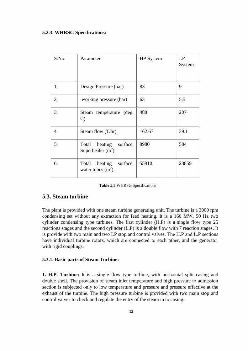
5.2.3. WHRSG Specifications:
Table 5.3 WHRSG Specifications
5.3. Steam turbine
The plant is provided with one steam turbine generating unit. The turbine is a 3000 rpm
condensing set without any extraction for feed heating. It is a 160 MW, 50 Hz two
cylinder condensing type turbines. The first cylinder (H.P) is a single flow type 25
reactions stages and the second cylinder (L.P) is a double flow with 7 reaction stages. It
is provide with two main and two LP stop and control valves. The H.P and L.P sections
have individual turbine rotors, which are connected to each other, and the generator
with rigid couplings.
5.3.1. Basic parts of Steam Turbine:
1. H.P. Turbine: It is a single flow type turbine, with horizontal split casing and
double shell. The provision of steam inlet temperature and high pressure to admission
section is subjected only to low temperature and pressure and pressure effective at the
exhaust of the turbine. The high pressure turbine is provided with two main stop and
control valves to check and regulate the entry of the steam in to casing.
12
S.No. Parameter HP System LP
System
1. Design Pressure (bar) 83 9
2. working pressure (bar) 63 5.5
3. Steam temperature (deg.
C)
488 207
4. Steam flow (T/hr) 162.67 39.1
5. Total heating surface,
Superheater (m2)
8980 584
6. Total heating surface,
water tubes (m2)
55910 23859

2. L.P. Turbine: it is a three cell design and has a double flow system for max
efficiency. The inner casing caries the first row of stationary blades and is supported on
the outer casing so as to allow for thermal expansion. The middle casing rest on four
girders, independent of the outer casing. The LP turbine is provided with two control
valves.
3. Bearing: The HP rotor is supported on two bearings, a combined journal bearing
close to the coupling with LP rotor. The LP journal bearing at its end. The bearing pedestals are anchored to the foundation and are fixed in position.
5.3.2. Working of steam turbine:
The HP steam is fed to the HP section of the steam turbine. The steam passes through
the stop and control valves of the HP turbine and enters the inner casing. On entering
the inner casing the steam after leaving the HP turbine gets converted into LP steam.
This LP steam produced at the WHRSG is passed into the inlet of the double flow LP
turbine. On entering the steam once again expands and due to the combined effect of
HP&LP rotors, the generator rotor also rotated and electricity is produced. The two
outlet of the LP turbine are connected to the condenser where water and steam mixture
are connected into water for further use in the WHRSG.
5.3.2. Specifications of HP Turbine:
TYPE Single flow
No. of stages 25 reaction stages
Total H.P main steam pressure 76.4 bar
HP main steam temp. 528 deg c
HPT exhaust pressure 5.1 bar
HPT exhaust temp. 175 deg
Table 5.4 Specifications of HP Turbine
5.3.3. Specifications of LP Turbine:
Type Double flow
No. Of stages 7 reaction stages
Total LP steam flow 46 T/hr
LP main steam pressure 4.38 bar
Table 5.5 Specifications of LP Turbine
13

5.3.5. Steam turbine specification:
manufacturer BHEL(haridwar, India)
type 2 cylinder condensing turbine
capacity 156.07MW
Maximum terminal outputs 160 MW
Main steam pressure 76.4 and 4.38 bar
Condenser vacuum -0.92 bar
speed 3000 rpm
Steam turbine generator 160000 W/188230 VA
Stator current 6900 amp
coolant air
insulation Class F
Power factor 0.85 lag
Excitation system Brush less excitation
Rotor voltage 432 V
Rotor current 797 amp
Table 5.6 Steam turbine specification
14
1

6. SWITCHYARD
The switch yard is the place from where the electricity is send outside. We know that
electrical energy can’t be stored like cells, so what we generate should be consumed
instantaneously. But as the load is not constant, therefore we generate electricity
according to need i.e. the generation depends upon load. It has both outdoor and indoor
equipments.
6.1 Outdoor Equipments
Bus Bar
Circuit Breaker
Lightening Arrester
Earth Switch
Capacitor Voltage Transformer
Wave Trap
PLCC
Current Transformer
Isolators
Potential Transformer
6.2 Indoor Equipments
Relays
Control Panels
6.1.1 Bus Bar
There are three buses viz. two main buses (bus 1 and bus 2) and one transfer bus. The
two main buses are further divided into two sections thus giving us a total of five buses.
Bus bars generally are of high conductive aluminum conforming to IS-5082 or copper of
adequate cross section .Bus bar located in air –insulated enclosures & segregated from
all other components .Bus bar is preferably cover with polyurethane.
6.1.2 Circuit Breaker
The code for circuit breaker is 52. An electric power system needs some form of
switchgear in order to operate it safely & efficiently under both normal and abnormal
conditions. Circuit breaker is an arrangement by which we can break the circuit or flow
of current. A circuit breaker in station serves the same purpose as switch but it has many
added and complex features. The basic construction of any circuit breaker requires the
separation of contact in an insulating fluid that servers two functions:
15

It extinguishes the arc drawn between the contacts when circuit breaker opens.
It provides adequate insulation between the contacts and from each contact to earth.
The insulating fluids commonly used in circuit breakers are:
Compressed air
Oil which produces hydrogen for arc excitation.
Vacuum
Sulphur hexafluoride (SF6 )
There are two makes of Circuit Breakers used at NTPC Faridabad switchyard:
i. SF6 Circuit Breaker – manufactured by ALSTOM
ii. Gas Circuit Breaker – manufactured by CGL
6.1.3 Lightening Arrester
These are provided to combat the effect of over voltages and surges caused due to
lighting strokes on the transmission lines. These are generally provided at the end near
the instrument which we want to protect. The lightening arrestors provide an easy path to
the surge current to the ground thereby not letting the Equipments to fail.It saves the
transformer and reactor from over voltage and over currents.
It has a round metal cap type structure on the top called CORONA RING, meant for
providing corona losses.
A meter is provided which indicates the surface leakage and internal grading current of
arrester.
Green – arrester is healthy
Red – arrester is defective
In case of red, we first de-energize the arrester and then do the operation.
Fig 6.1 Lightening Arrester
16

6.1.4 Air Break Earthing Switch
These are used to ground the circuit and to discharge the CB when CB is in off
condition.
The code of earthling switch is 5, 6, 7.The work of this equipment comes into picture
when we want to shut down the supply for maintenance purpose. This help to neutralize
the system from induced voltage from extra high voltage. This induced power is up to
2KV in case of 400 KV lines.
Table 6.1 Specifications of earthing switch
6.1.5 Capacitor Voltage Transformer (CVT)
The carrier current equipment can be connected via the capacitor of CVT. Thereby
there is no need of separate coupling capacitor. The reactor connected in series with
the burden is adjusted to such a value that at supply frequency it resonates with the
sum of two capacitors. This eliminates the error. CVT is attached at end of each
transmission, line and buses.
The CVT is used for line voltage measurements on loaded conditions. The basic
construction of a cvt is as follows. Each CVT consists of a coupling capacitor (CC)
which acts as a voltage driver and an Electro Magnetic Unit (EMU) which transforms
the high voltage to standard low voltage. Depending on the system voltage the CC
can be a single or a multi stack unit. 245 kV & 420kV CVTs no normally comprise
of 2 units.
Fig 6.2 Capacitor Voltage Transformer
17
Make Voltage Motor volt (ac) Control volt (dc)
S & S power 245 kV 415 volts 220 volts

The main points of difference between a CVT and a potential transformer (PT) is that in
a PT full line voltage is impressed upon the transformer while in cvt line voltage after
standard reduction is applied to the transformer.
It is used for three purposes:
Metering
Protection
PLCC
6.1.6 Wave Trap
It is used in PLCC system to trap frequency higher than 50 Hz. It is lightly inductive
having very less resistance. It is attached at each end of transmission line. It is of
cylindrical shape mounted on top of the transmission line.
Fig 6.3 Wave Trap
6.1.7 PLCC (Power Line Carrier Communication)
In addition to power supply transfer, transmission line is also used for communication
purpose. This is done by PLCC system. Here line conductors itself are used as channel
for carrying information between two end of line.
The PLCC system is used to trap the frequency higher than 50 Hz through high
inductance and low resistance along with a coupling capacitor. The main components of
PLCC are:-
Wave trap
Co-axial cable
CVT
PLCC cabinet
LMU ( Line matching Unit)
18

6.1.8 Current Transformer (CT)
These are used for stepping down AC current from higher value to lower value for
measurement, protection and control. Here N2 gas is used to prevent oil from moisture.
Its secondary winding has 5 cores.
Terminal 1,2,4,5 protection 3 Metering Turns ratio – 800/1
Fig 6.4 Current Transformer
6.1.9 Isolators
The isolators can be thought of switches that can either make or break the circuit at the
operator’s wish.
Sequence of operation while opening / closing a circuit:
While opening: open circuit breaker open isolator close earthing switch (if any)
While closing: ensure circuit breaker is open close isolator open earthing switch
close circuit breaker.
It is used as off line circuit breaker. It is normally used for purpose of isolating a certain
portion when required for maintenance. It operates at 2000 A.
In switchyard there are 3 types of isolators:
Line isolator
Transfer bus isolator
Bus isolator
Fig 6.5 Isolators
19

7. GENERATOR
The transformation of mechanical energy into electrical energy is carried out by the
generator. The generator also called the alternator is based upon the principle of
electromagnetic induction. The stator houses the armature windings and the rotor houses
the field windings. The alternator is a doubly excited system and the field is excited from
dc supply whereas the output received from the alternator is ac.
When the rotor is energised the flux lines emitted by it are cut by the stator windings
which induces an emf in them given by
E = 4.44 f Φ N
Where f frequency in Hz
Φ field strength in webers/m2
N speed of rotor in rpm
Turbo generators run at a very high speed hence the no. of poles are generally two or
four and have a cylindrical rotor construction with small diameter and long axial length.
7.1 Main components
The main components of a generator are the rotor and stator.
7.1.1 Rotor
Body: The electrical rotor is the most difficult part of the generator to design. It is an
electromagnet and to give it the required strength of magnetic field a large current is
required to flow through it.
Rotor winding: Silver bearing copper is used for the winding with mica as the insulation
between conductors. Rotor has hollow conductors with slots to provide for circulation of
the cooling gas.
Rotor balancing: The rotor must then be completely tested for mechanical balance
which means that a check is made to see if it will run upto normal speed without
vibration.
7.1.2 Stator
Stator frame: It is the heaviest load to be transported. The major part is the stator core.
This comprises an inner frame and an outer frame. The outer frame is a rigid fabricated
structure of welded steel plate. In large generator the outer casing is done in two parts.
Stator core: it is the heaviest part and is built from a large no. of thin steel plates or
punching.
Stator windings: It is of lap type and employs direct water cooled bar type winding. The
stator winding bar is made from glass lapped elementary conductor and hollow
conductors. The main insulation is applied by means of mica tape which is wrapped and
is compounded with the help of a silicon epoxy compound.
20

KVA Pf Stator
Voltage
(V)
Stator
Current
(A)
Rotor
Voltage
(V)
Rotor
Current
(A)
Rpm Hz Phase Coolant
247000 0.85 15750 9050 310 2600 3000 50 3 Water
(stator)&
hydrogen
(rotor)
Table 7.1 Generator Specifications
7.2 Excitation System
Static Excitation System-The generators in stage -1(U-1&U-2) have this excitation
system. Static excitation system has slip ring and carbon brush arrangement. It
consists of step down transformer, converter and AVR (automatic voltage regulator).
Brushless Excitation System –The generators in stage -2(U-3, U-4& &U- 5) have
this excitation system. It has two exciters, one is main exciter and other is pilot
exciter.
7.3 Generator Protection
Stator Protection- The neutral of star connected winding is connected to primary of
neutral grounding transformer, so that earth fault current is limited by over voltage
relay.
Differential Protection- In case of phase-to-phase fault generator is protected by
longitudinal differential relay.
Rotor Protection-Rotor winding may be damaged by earth faults or open circuits.
The field is biased by a dc voltage, which causes current to flow through the relay for
an earth fault anywhere on the field system.
Over Speed Protection –Mechanically over speed device that is usually in the form
of centrifugally operated rings mounted on the rotor shaft, which fly out and close the
stop valves if the speed of the set increase more than 10%.
Over Voltage Protection – It is provided with an over voltage relay. The relay is
usually induction pattern. The relay open the main circuit break and the field switch if
the over voltage persists.
Seal Oil System –is a possibility of this hydrogen to come out of gaps, which is very
hazardous. So, seal oil is used to seal the gaps so that hydrogen doesn’t come out.
21
Lubrication Oil System –Turbine lubrication-oil system seeks to provide proper
lubrication of turbo generator bearings and operation of barring gear. Pumps are used
to circulate lubrication-oil inside the generator. The oil of the lubrication and the
governing system is cooled in the oil coolers. The cooling medium for these coolers is
circulating water.
7.4 Generator Cooling System
Turbogenerator is provided with an efficient cooling system to avoid excessive heating
and consequent wear and tear of its main components during operation. The two main
systems employed for cooling are water cooling system and hydrogen cooling system.
Hydrogen cooling system: Hydrogen is used as a cooling medium in large capacity
generator in view of the following feature of hydrogen. When hydrogen is used as a
coolant the temperature gradient between the surface to be cooled and the coolant is
greatly reduced. This is because of the high coefficient of heat transfer of hydrogen.The
cooling system mainly comprises of a gas control stand, a driver, hydrogen control panel,
gas purity measuring instrument and an indicating instrument, valves and the sealing
system. A great care should be taken so that no oxygen enters the cooling system
because hydrogen forms an explosive mixture with air. The purity of hydrogen be
maintained as high as 98%.to produce hydrogen in such large quantities a separate plant
called the hydrogen plant is also maintained.
Water cooling system: Turbo generators require water cooling arrangement. The stator
winding is cooled by circulation of demineralised water through hollow conductors. The
system is designed to maintain a constant rate of cooling water flow to the stator winding
at a nominal temperature of 40 deg Celsius.
7.5 Cooling Specifications of Turbo generators At FGPS
Stage-I:
Water as well as hydrogen cooling is present in stage-I turbo generators with following
specifications:
Rotor cooling: Hydrogen gas pressure: 3.5 Kg/cm2, Purity: 98%
Stator cooling: Water pressure: 3.5 Kg/cm2, Rate of flow of water: 130 m3/hr
Stage-II & III:
Only hydrogen cooling is used for both stator and rotor cooling.
Rotor cooling: Hydrogen gas pressure: 3.5 Kg/cm2, Purity: 98%
Stator cooling: Hydrogen gas pressure: 2.0 Kg/cm2, Purity: 98%
22

8. TRANSFORMERS
The transformer is a device that transfers electrical energy from one electrical circuit to
another through the medium of magnetic field and without the change of frequency. It is
an electromagnetic energy conversion device, since the energy received by the primary is
first converted to magnetic and is then reconverted to electrical energy in the secondary.
Thus these windings are not connected electrically but coupled magnetically. Its
efficiency is in the range of 97 to 98 %.
8.1 Transformer accessories
Conservator: with the variation of temperature there is a corresponding variation in
the volume of oil due to expansion and contraction of oil caused by the temperature
change. To account for this, an expansion vessel called the conservator is connected
to the outside atmosphere through a dehydrating breather to keep the air in the
conservator dry. An oil gauge shows the level of oil in the conservator.
Breather: it is provided to prevent the contamination of oil in the conservator by the
moisture present in the outside air entering the conservator. The outside air is drawn
into the conservator every time the transformer cools down which results in the
contraction of the volume occupied by the oil in the conservator. The breather
contains a desiccator usually Silica gel which has the property of absorbing moisture
from the air. After sometime silica gel gets saturated and then it changes it colour
from purple to pink indicating that it has become saturated and hence needs to be
replaced or regenerated.
Relief vent: In case of severe internal fault in the transformer, the pressure may be
built to a very high level which may result in the explosion in the tank. Hence to
avoid such condition a relief vent is provided with a bakelite diaphragm which breaks
beyond certain pressure and releases the pressure.
Bushings: they consist of concentric porcelain discs which are used for insulation
and bringing out the terminals of the windings from the tank.
Buchcholz relay: this is a protection scheme for the transformer to protect of against
anticipated faults. It is applicable to the oil immersed transformer and depends on the
fact that transformer breakdowns are always preceded by violent generation of gas
which might occur due to sparking or arcing.
Temperature indicators: transformers are provided with two temperature indicators
that indicate the temperature of the winding and that of the oil in the transformer for
an oil filled transformer.
23

The temperature indicators are also protective in nature whereby the first create an
alarm and then trip the respective transformer in case the temperature of the
respective parts rises beyond a certain value.
Tap changers: these are also provided and are mounted on the transformer. In case
some kind of load fluctuations the taps can be changed or adjusted as per the need.
There are two types of tap changers: On load tap changer and off load tap changer.
8.2 Cooling Of Transformers
Heat is produced in the transformers due to the current flowing in the conductors of the
windings and on account of the eddy current in the core and also because of the
hysteresis loss. In small dry type transformers the heat is directly dissipated to the
atmosphere. In oil immersed systems oil serves as the medium for transferring the heat
produced. Because of the difference in the temperatures of the parts of the transformers
circulating currents are set. On account of these circulating currents hot oil is moved to
the cooler region namely the heat exchanger and the cooler oil is forced towards the hot
region. The heat exchangers generally consist of radiators with fins which might be
provided with forced or natural type air circulation for removal of heat.
The oil in oil immersed transformers may also be of forced or natural circulation type.
The oil used for cooling is silicone oil or a mixture of naphthalene and paraffin. When
forced oil circulation is used then pumps are used for the circulation of the oil. The oil
forced air forced type cooling is used in large transformers of very high KVA rating.
1. Simple Cooling
AN: Natural cooling by atmospheric circulation, without any special devices. The
transformer core and coils are open all round to the air. This method is confined to very
small units at a few kV at low voltages.
AB: In this case the cooling is improved by an air blast, directed by suitable trunking and
produced by a fan.
ON: The great majority of transformers are oil-immersed with natural cooling, i.e. the
heat developed in the cores and coils is passed to the oil and thence to the tank walls,
from which it is dissipated.
OB: In this method the cooling of an ON-type transformer is improved by air blast over
the outside of the tank.
OFN: The oil is circulated by pump to natural air coolers.
OFB: For large transformers artificial cooling may be used. The OFB method comprises
a forced circulation of the oil to a refrigerator, where it is cooled by air-blast.
OW: An oil-immersed transformer of this type is cooled by the circulation of water in
cooling tubes situated at the top of the tank but below oil-level.
OFW: Similar to OFB, except that the refrigerator employs water instead of air blast for
cooling the oil, which is circulated by pump from the transformer to the cooler.
24

2. Mixed Cooling
ON/OB: As ON, but with alternative additional air-blast cooling. ON/OFN, ON/OFB,
ON/OFW, ON/OB/OFB, ON/OW/OFW.
A transformer may have two or three ratings when more than one method of cooling is
provided. For an ON/OB arrangement these ratings are approximately in the ratio 1/1.5;
for ON/OB/OFB in the ratio 1/1.5/2.
8.3 Main Transformers
i. Generator Transformer: This is a step up transformer. This supply gets its primary
supply from generator and its secondary supplies the switchyard from where it is
transmitted to grid. This transformer is oil cooled. The primary of this transformer is
connected in star. The secondary is connected in delta. These are two in number.
ii. Station Transformer: This transformer has almost the same rating as the generator
transformer. Its primary is connected in delta and secondary in star. It is a step down
transformer. These are 4 in number.
iii. Unit Auxiliary Transformer: This is a step down transformer. The primary receives
from generator and secondary supplies a 6.6 KV bus. This is oil cooled. These are 10
in number.
iv. Neutral Grounded Transformer: This is used to ground the excess voltage if
occurs in the secondary of UAT in spite of rated voltage.
Fig 8.1 3-Phase Transformers
25

9. D.C SYSTEM
9.1 Requirement of DC System
There are some auxiliaries which need to run even when the ac supply fails such as seal
oil pumps, the scanner system, valve control, lights, etc. So we require the DC system.
All the circuit breakers in the power plant operate on DC. The DC system comprises of
batteries, chargers & control circuit to maintain a continuous supply for the DC feeders.
There are five units in unchahar power plant and in each unit separate battery rooms are
made from which we have 220V as well as 24V DC supply.
9.2 Description of battery:
Capacity = 220 V (1400 AH) / 24 V (400 AH)
Per unit cell = 2.2 V
Battery plate:
Positive terminal = PbO2
Negative terminal = Pb
Electrolyte = H2SO4
Reactions occurring in the battery:
i. At the time of charging:
At positive plate –
PbSO4 + SO4 + 2H2O PbO2 + 2H2O
At negative plate –
PbSO4 + H2 Pb + H2S
ii. At the time of Discharging:
At positive plate –
PbO2 + H2 + H2SO4 PbSO4 + 2 H2O
At negative plate –
Pb + SO4 PbSO4
9.3 Battery charger
Battery charger normally operates in two modes.
Float charging: It is constant voltage mode and works as a trickle charger.
Boost charging: It is constant current mode and works as a quick charger.
Trickle Charger – It operates at 220V. It is used for continuous charging of the battery.
Full time battery is charged by the trickle charger and remains in float condition.
Quick charger – It is also known as Boost Charger. This is used at the time of
overhauling. It operates in two modes –
i. Constant current (CC) ii. Constant Voltage (CV)
26

10. SWITCHGEAR
Switchgear is an electrical functional switch used for starting any drive and provide
protection to the drive during on load condition. It is of two types:-
Low tension switchgear (below 1000 V)
High tension switchgear (above 1000 V)
10.1 L.T Switchgear
OPERATING VOLTAGE- 415VOLT
The main components are:
Relays: the purpose of protective relaying system is to operate the circuit breaker so
as to disconnect only the faulty equipment from the system as quickly as possible thus
minimizing the trouble and damage caused by faults when they do occur. The general
relay used is BMR (Bi-Metallic Relay). It trips due to thermal overloading when
overcurrent passes through the bimetallic strips causes different expansions in
different parts as a result the BMR strip is bent.
Contactors: these are used on-load operations under normal conditions. Contactor is
a mechanical switching device capable of making carrying and breaking electric
current under normal circuit conditions including operating overload conditions
Isolators: These are disconnecting switches used for off-load operations. These are
operated manually. Before operation power is switched off. Isolators are kept in
closed position when the system components are in operation. During any
maintenance work isolators are kept open.
Fuses: It is a device used in circuit for protecting electrical equipments against
overload or short circuit. The fuse wire melts when an excessive current flows in the
circuit and thus isolates the faulty device from the supply circuit.
10.2 H.T. Switchgear OPERATING VOLTAGE - 6.6KV
For low voltage circuits fuses may be used to isolate the faulty circuit. For voltage higher
than 3.3 kV isolation is achieved by circuit breaker.
Requirement of circuit breaker:
After occurrence of fault the switchgears must isolate the faulty circuit as quickly
as possible i.e. keeping the delay to minimum.
It should not operate when an over current flows under healthy condition.
27

Basic principal of operation of circuit breaker:
Circuit breaker consists of a fix contact and sliding contact into which moves a moving
contact. The end of moving contact it attached to a handle that can be manually operated
or may operate automatically with the help of mechanism that has a trip coil energized
by secondary of CT. Under normal condition the secondary of CT is not energized
sufficiently to trip the coil but under false condition the coil is energized fully to operate
the trip coil and the circuit breaker is operated.
MOCB (Minimum oil circuit breaker)
SF6 (Sulphur hexafluoride circuit breaker)
Here oil and SF6 are used to quench the arc.
Bus ducts:
These serve as interconnection between transformer and switchgear and are non-
segregated phase type. These are natural air cooled.
Bus coupler:
It acts as interconnection between the two buses. If the supply of one bus fails then the
bus coupler connects the two buses and charges the bus from the other bus.
Different relays used:
Motor protection system
Earth fault relay
Over load relay
Lock out relay
Check synchronizing relay
Differential protection relay
Auxiliary relay
10.3 Variable frequency drive:
Fig 10.1 Electrical scheme of VFD
28

The panel in the figure is a variable frequency drive panel. Using variable frequency
drive voltage is compensated at low frequencies, the torque at low speeds is improved.
To obtain the voltage boost, we require a controlled converter as well as a controlled
inverter.
First the three phase supply from transformer is fed to the controlled rectifier which the
ac to dc. The advantage of using a controlled rectifier is that the average value of the
output can be controlled by varying the firing angle. Then its output is fed to the inverter
which is a type of load commutated inverter. Before passing it to the inverter a reactor is
also employed in between this reduces the ripples. The inverter then converts dc to ac
and the ac is fed to the synchronous motor. The speed of synchronous motor is fixed and
is given by 120 f / p. since the only thing variable in the expression is the frequency
which is directly proportional to the speed. Hence the inverter varies the frequency and
hence controls the speed of the motor. The controlled rectifier in the circuit is used for
voltage control while the load commutated inverter is used for frequency variation.
10.3.1 Advantages of Variable Frequency Drive:
1. Speed control is fine as the frequency is varied from 0.5Hz to 47.5 Hz.
2. Very low starting current as motor starts on reduced voltage.
3. Power consumption is low.
4. Motor life is improved
10.4 Two channel arrangement for synchronous motor:
The stator of the synchronous motor is given supply using two channels. Normally the
motor works on both channels but under some faulty conditions on any one of the
channels the other channel can continue working since the motor is required for
continuous operation
Fig 10.2 Two channel arrangement of synchronous motor
29

11. CONCLUSION
On completion of my vocational training at NTPC Faridabad, I have come to know about
how the very necessity of our lives now a days i.e. how electricity is generated & what
all processes are needed to generate and run the plant on a 24x7 basis.
NTPC Faridabad is one the plants in India to be under highest load factor for the
maximum duration of time and that to operating at highest plant efficiencies. This plant
is an example in terms of working efficiency and management of resources to all other
thermal plants in our country. The operating pf of the NTPC as compared to the rest of
country is the highest with 95 % the highest since its inception.
The training gave me an opportunity to clear my concepts from practical point of view
with the availability of machinery of diverse ratings.
30

REFERENCES
[1] N.T.P.C. magazines. [2] Google [3] Wikipedia [4] N.T.P.C. Websites.
31