Final Report on Combining SysML and CML - · PDF fileFinal Report on Combining SysML and CML...
219
Grant Agreement: 287829 Comprehensive Modelling for Advanced Systems of Systems Final Report on Combining SysML and CML Document Number: D22.4 Version: 1.0 Date: March 2013 Public Document http://www.compass-research.eu
Transcript of Final Report on Combining SysML and CML - · PDF fileFinal Report on Combining SysML and CML...
Grant Agreement: 287829
Comprehensive Modelling for Advanced Systems of Systems
Final Report on Combining SysML and CML
Document Number: D22.4
Version: 1.0
Date: March 2013
Public Document
http://www.compass-research.eu
D22.4 - SysML–CML (Public)
Contributors:
Alvaro Miyazawa, YorkAna Cavalcanti, YorkJuliano Iyoda, UFPEMárcio Cornélio, UFPELucas Albertins, UFPERichard Payne, UNEW
Editors:
Alvaro Miyazawa, York
Reviewers:
Ralph Hains, AtegoStefan Hallerstede, Aarhus UniversityKlaus Kristensen, B&O
2
D22.4 - SysML–CML (Public)
Document History
Ver Date Author Description0.00 30-07-2012 Alvaro Miyazawa Initial document version.0.01 20-11-2012 Alvaro Miyazawa Included material on guidelines and
meta language.0.02 06-12-2012 Alvaro Miyazawa Updated with Ana’s comments.0.03 10-12-2012 Alvaro Miyazawa Included the semantics of simple
blocks.0.04 12-12-2012 Alvaro Miyazawa Included the semantics of state ma-
chine diagrams.0.05 16-01-2013 Lucas Albertins Included the semantics of sequence
diagrams.0.06 21-12-2012 Alvaro Miyazawa Included the semantics of ports, and
added SysML example in Chapter 2.0.07 28-12-2012 Alvaro Miyazawa Included the semantics of composite
blocks, and completed SysML exam-ple in Chapter 2.
0.08 30-12-2012 Alvaro Miyazawa Reviewed guidelines and examplesection.
0.09 31-12-2012 Alvaro Miyazawa Reviewed and completed conclu-sions.
0.10 31-12-2012 Alvaro Miyazawa Completed structural diagrams chap-ter.
0.11 05-02-2013 Márcio Cornélio Included the semantics of activity di-agrams.
0.12 22-02-2013 Alvaro Miyazawa First review of parts of introductionand structural diagrams.
0.13 28-02-2013 Alvaro Miyazawa Review of state machine diagrams.0.14 07-03-2013 Alvaro Miyazawa Review of parts of introduction,
structural and state machine dia-grams, and conclusions.
0.15 27-03-2013 Alvaro Miyazawa Addressed comments from the inter-nal reviewers.
1.0 28-03-2013 Alvaro Miyazawa Final version ready for submission.
3
Abstract
The Systems Modeling Language (SysML) is becoming a de-facto standard in thesystems engineering community, and has been considered as a potential graphi-cal notation for the design and analysis of Systems of Systems. This deliverableaims at providing a formal account to a representative subset of SysML to supportformal analysis of models specified in this notation.
This goal is achieved by means of a formal semantics of SysML diagrams, whichin this work is defined in terms of Compass Modelling Language (CML). Thechoice of CML as the semantic domain for SysML models is motivated by theability to explore the CML theories and tools in the analysis of the models. In thisreport we target three SysML behavioural diagrams, namely, activity, sequenceand state machine diagrams, and two structural diagrams, namely, block definitiondiagrams and internal block diagrams. The semantics of blocks in fact gives anintegrated semantics of multi-diagram SysML models.
We identify a set of guidelines of usage for SysML diagrams that support the def-inition of a self-contained semantics of SysML models. Additionally, we identifya subset of diagram constructs that are more frequently used. Based on theseguidelines, we propose a formal denotational semantics of SysML models. Thesemantics is defined by a inductive function from the abstract syntax of SysML tothe abstract syntax of CML. The semantic function is specified by a set of trans-lation rules that apply to particular constructs of SysML.
4
D22.4 - SysML–CML (Public)
Timetable:Date
First version for contributor’s review 01.10.12Second version for contributor’s review 01.01.13Final version for internal review 08.03.13Reviewer’s comments 22.03.13Final version for submission 29.03.13
5

Contents
1 Introduction 91.1 Motivation . . . . . . . . . . . . . . . . . . . . . . . . . . . . . . 91.2 Objectives . . . . . . . . . . . . . . . . . . . . . . . . . . . . . . 12
2 Preliminaries 142.1 CML . . . . . . . . . . . . . . . . . . . . . . . . . . . . . . . . . 142.2 SysML . . . . . . . . . . . . . . . . . . . . . . . . . . . . . . . . 202.3 Example . . . . . . . . . . . . . . . . . . . . . . . . . . . . . . . 302.4 Final remarks . . . . . . . . . . . . . . . . . . . . . . . . . . . . 36
3 Formal semantics of SysML models 373.1 Guidelines . . . . . . . . . . . . . . . . . . . . . . . . . . . . . . 373.2 Semantic rules metalanguage . . . . . . . . . . . . . . . . . . . . 423.3 Overview of the semantics of SysML models . . . . . . . . . . . 443.4 Final remarks . . . . . . . . . . . . . . . . . . . . . . . . . . . . 47
4 Structural diagrams 494.1 Overview . . . . . . . . . . . . . . . . . . . . . . . . . . . . . . 504.2 Operations and signals . . . . . . . . . . . . . . . . . . . . . . . 534.3 Interfaces . . . . . . . . . . . . . . . . . . . . . . . . . . . . . . 554.4 Standard ports . . . . . . . . . . . . . . . . . . . . . . . . . . . . 574.5 Simple blocks . . . . . . . . . . . . . . . . . . . . . . . . . . . . 61
4.5.1 Simple blocks: types . . . . . . . . . . . . . . . . . . . . 614.5.2 Simple blocks: channels . . . . . . . . . . . . . . . . . . 644.5.3 Simple blocks: processes . . . . . . . . . . . . . . . . . . 65
4.6 Composite blocks . . . . . . . . . . . . . . . . . . . . . . . . . . 724.7 Final remarks . . . . . . . . . . . . . . . . . . . . . . . . . . . . 77
5 State machine diagrams 795.1 Examples . . . . . . . . . . . . . . . . . . . . . . . . . . . . . . 815.2 Formal semantics . . . . . . . . . . . . . . . . . . . . . . . . . . 86
6
D22.4 - SysML–CML (Public)
5.2.1 Event controller . . . . . . . . . . . . . . . . . . . . . . . 875.2.2 Internal state machine . . . . . . . . . . . . . . . . . . . 905.2.3 State . . . . . . . . . . . . . . . . . . . . . . . . . . . . 955.2.4 Regions . . . . . . . . . . . . . . . . . . . . . . . . . . . 1085.2.5 Final states . . . . . . . . . . . . . . . . . . . . . . . . . 1125.2.6 Non-completion transitions . . . . . . . . . . . . . . . . . 1145.2.7 Completion transitions . . . . . . . . . . . . . . . . . . . 1205.2.8 Join and Fork pseudostates . . . . . . . . . . . . . . . . . 1225.2.9 Initial pseudostates . . . . . . . . . . . . . . . . . . . . . 1265.2.10 Actions . . . . . . . . . . . . . . . . . . . . . . . . . . . 127
5.3 Related work . . . . . . . . . . . . . . . . . . . . . . . . . . . . 130
6 Sequence diagrams 1326.1 Examples . . . . . . . . . . . . . . . . . . . . . . . . . . . . . . 1326.2 Formal semantics . . . . . . . . . . . . . . . . . . . . . . . . . . 134
6.2.1 Root Sequence Diagram . . . . . . . . . . . . . . . . . . 1346.2.2 Lifeline . . . . . . . . . . . . . . . . . . . . . . . . . . . 1406.2.3 Messages . . . . . . . . . . . . . . . . . . . . . . . . . . 1416.2.4 Combined Fragments . . . . . . . . . . . . . . . . . . . . 1466.2.5 State Invariant . . . . . . . . . . . . . . . . . . . . . . . 1546.2.6 InteractionUse . . . . . . . . . . . . . . . . . . . . . . . 155
6.3 Related work . . . . . . . . . . . . . . . . . . . . . . . . . . . . 163
7 Activity diagrams 1667.1 Examples . . . . . . . . . . . . . . . . . . . . . . . . . . . . . . 1667.2 Formal semantics . . . . . . . . . . . . . . . . . . . . . . . . . . 168
7.2.1 Block Activity Diagrams . . . . . . . . . . . . . . . . . . 1697.2.2 Single Activity Diagram . . . . . . . . . . . . . . . . . . 1737.2.3 Call Behaviour Action Parallelism . . . . . . . . . . . . . 1747.2.4 Internal Activity Diagram . . . . . . . . . . . . . . . . . 1757.2.5 Start Activity . . . . . . . . . . . . . . . . . . . . . . . . 1797.2.6 Interruptible Regions . . . . . . . . . . . . . . . . . . . . 1807.2.7 End Activity . . . . . . . . . . . . . . . . . . . . . . . . 1817.2.8 Actions . . . . . . . . . . . . . . . . . . . . . . . . . . . 1837.2.9 Control Nodes . . . . . . . . . . . . . . . . . . . . . . . 1927.2.10 Object Nodes . . . . . . . . . . . . . . . . . . . . . . . . 200
7.3 Related work . . . . . . . . . . . . . . . . . . . . . . . . . . . . 205
8 Conclusions 2088.1 Summary . . . . . . . . . . . . . . . . . . . . . . . . . . . . . . 2088.2 Validation . . . . . . . . . . . . . . . . . . . . . . . . . . . . . . 210
7
D22.4 - SysML–CML (Public)
8.3 Refinement in SysML . . . . . . . . . . . . . . . . . . . . . . . . 210
A Omitted translation rules 212
8

Chapter 1
Introduction
In this report, we propose a formal semantics of SysML based on the CML no-tation. We identify a set of guidelines of usage for SysML diagrams that supportthe definition of a self-contained semantics of SysML models. Additionally, weidentify a subset of diagram constructs that are more frequently used.
Based on these guidelines, the semantics of SysML is given as a translation fromthe abstract syntax of SysML to the abstract syntax of CML. Our translation isformalised by semantic functions that can also be regarded to define a refinementsemantics for SysML diagrams using CML. The functions are defined by transla-tion rules, and are inductive on the structure of SysML models.
In particular, we address the translation to CML of model that include the fol-lowing diagrams: block definition diagrams, internal block diagrams, activity dia-grams, sequence diagrams, and state machine diagrams. The translations are per-formed by applying translation rules according to a pre-defined strategy. The partsof the model represented by the different diagrams are translated by following spe-cific strategies. All translation strategies are systematic and mechanisable.
In the next sections, we discuss our motivations (Section 1.1) and give an overview(Section 1.2) of the approach taken to linking SysML and CML.
1.1 Motivation
The design of Systems of Systems (SoS) is a field of study that presents majorchallenges due to their complexity. Traditional approaches lack in support foranalysis during the development process, which leads to inefficiencies in cost,
9
D22.4 - SysML–CML (Public)
time and design. COMPASS (Comprehensive Modelling for Advanced Systemsof Systems) aims at extending the industrial practise by means of a set of toolsand techniques that support a formally grounded model-based approach for thedevelopment of SoS.
In this context, the work reported in this document is directly related to the linkbetween the industrial practice and the formal world. By linking a current indus-trial notation (SysML) with a formal notation (CML), a new realm of tools andtechniques become available to SysML. Informal development can be carried outwith the additional guidance of the analysis techniques supported by CML, and,when needed, formal development can be introduced.
SysML diagrams are intended to describe views on an underlying model that en-sures informally the consistency between the model elements contained in thosediagrams. It is not possible, however, to give a (useful) formal semantics to anarbitrary collection of SysML diagrams. They do have a standardised syntax andclearly identified well formedness rules [Obj10a]. However, SysML places norestriction on the semantics of some its elements. For example, there is no restric-tion on the meaning of a block in a block definition diagram (BDD), nor on what itmay represent. The diagrams of SysML may be used in several ways, and their useis dependent on the subject being modelled. We must, however, ensure formallythat the diagrams are used in a consistent manner. Therefore, we propose guide-lines that restrict the usage of the diagrams and define the semantics of SysML forthat particular usage, so that a useful CML model can be produced.
Modelling patterns, such as those prescribed by Holt et al. [HP08, Hol09], pro-vide a systematic method for producing architectural models. For example, Holtdefines a pattern for business process modelling that consists of a collection ofviews in the form of SysML diagrams, describes the consistency rules betweenthose views, and a method for defining diagrams in a systematic manner [Hol09].An initial architectural modelling pattern for requirements engineering is givenby Holt et al. [HPM11], and is expanded to cover SoSs in [HPHH12]. One ofthe objectives of the COMPASS project is to define patterns for SoS modelling.Therefore, we aim to provide a method to be used by SoS engineers for defin-ing a SysML architectural model containing diagrams required for deriving CMLmodels. Such patterns define indirectly a semantics for the model elements of theSysML diagrams, and their relationship. It is this informal semantics that we cancapture formally in CML.
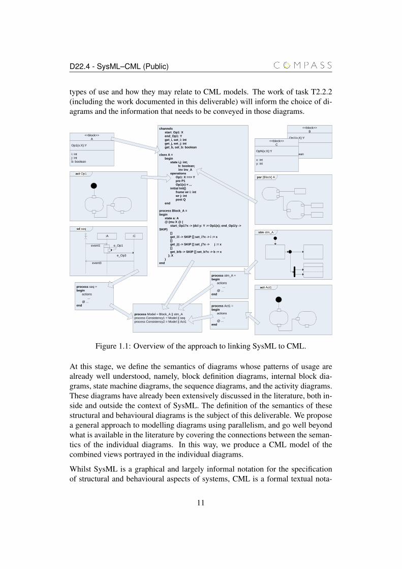
Such patterns are currently under development and discussion in COMPASS.Work package WP21 will provide an approach to defining architectural modelsfor SoSs using architectural patterns that inform the methods for developing SoSarchitectural models in SysML. Figure 1.1 provides an overview of the diagram
10
D22.4 - SysML–CML (Public)
types of use and how they may relate to CML models. The work of task T2.2.2(including the work documented in this deliverable) will inform the choice of di-agrams and the information that needs to be conveyed in those diagrams.
channels
start_Op1: X
end_Op1: Y
get_i, set_i: int
get_j, set_j: int
get_b, set_b: boolean
class A =
begin
state i,j: int;
b: boolean;
inv inv_A
operations
Op1: X ==> Y
pre P1
Op1(x) = ...
initial Init()
frame wr i: int
wr j: int
post Q
end
process Block_A =
begin
state a: A
@ (mu X @ (
start_Op1?x -> (dcl y: Y := Op1(x); end_Op1!y ->
SKIP)
[]
get_i!i -> SKIP [] set_i?x -> i := x
[]
get_j!j -> SKIP [] set_j?x -> j := x
[]
get_b!b -> SKIP [] set_b?x -> b := x
); X
)
end
<<block>>
A
Op1(x:X):Y
i: int
j: int
b: boolean
sd seq
:A :C
event1
event3
e_Op1
e_Op3
act Op1
process seq =
begin
actions
...
@ ...
end
process stm_A =
begin
actions
...
@ ...
end
stm stm_A
process Act1 =
begin
actions
...
@ ...
end
<<block>>
B
Op1(x:X):Y
i: int
j: int
b: boolean
<<block>>
C
OpN(x:X):Y
x: int
y: int
par [Block] A
process Model = Block_A || stm_A
process Consistency1 = Model || seq
process Consistency2 = Model || Act1
act Act1
Figure 1.1: Overview of the approach to linking SysML to CML.
At this stage, we define the semantics of diagrams whose patterns of usage arealready well understood, namely, block definition diagrams, internal block dia-grams, state machine diagrams, the sequence diagrams, and the activity diagrams.These diagrams have already been extensively discussed in the literature, both in-side and outside the context of SysML. The definition of the semantics of thesestructural and behavioural diagrams is the subject of this deliverable. We proposea general approach to modelling diagrams using parallelism, and go well beyondwhat is available in the literature by covering the connections between the seman-tics of the individual diagrams. In this way, we produce a CML model of thecombined views portrayed in the individual diagrams.
Whilst SysML is a graphical and largely informal notation for the specificationof structural and behavioural aspects of systems, CML is a formal textual nota-
11
D22.4 - SysML–CML (Public)
tion that supports the specification of systems in different levels of abstraction.Additionally, CML supports the specification of contracts, which is not directlysupported in SysML.
CML supports the specification of both state-rich behaviour and communication.The two central notions in CML are processes and refinement: processes encap-sulate behaviour and refinement supports the comparison of processes. A processmay be defined in terms of other processes or in terms of an encapsulated stateand actions that potentially modify the state. The actions are specified through amixture of CSP and VDM operators. The first set of operators focus on communi-cation (e.g., prefixing) and control structure (e.g., interleaving), whilst the secondset of operators focus on data aspects (e.g., assignment). The values manipulatedby data operations in CML are drawn from the types traditionally found in speci-fication languages (e.g., sets, sequences) as well as from classes. A class in CMLdeclares a state and a number of operations that manipulate the state. Operationsin CML are purely state operations, as opposed to actions, which support the fullrange of CML action constructors.
Additionally, CML supports step wise development by means of algebraic re-finement laws. The soundness of the refinement laws is established with respectto the formal semantics of CML, defined in the Unifying Theories of Program-ming [HJ98]. CML is still under development, with a COMPASS tool and severalanalysis plug-ins currently in production [CML+12]. In particular, tool supportfor CML will include a parser, a type-checker, a simulator, a theorem prover, amodel-checker and a refinement editor.
1.2 Objectives
In this document, we aim at setting the approach to realise the link betweenSysML and CML. We aim to identify those diagrams that provide details rele-vant to CML. As identified by Holt et al. [HNH+12], SysML has two main typesof diagram: structural and behavioural. The structural diagrams of SysML con-sist of block definition diagrams, internal block diagrams, package diagrams, andparametric diagrams. Behavioural diagrams include activity diagrams, sequencediagrams, state machine diagrams and use case diagrams. SysML also includesa new requirements diagram. For the basis of linking SysML and CML, we ini-tially define the semantics of the following diagrams: block definition diagrams,internal block diagrams, activity diagrams, sequence diagrams and state machinediagrams.
12
D22.4 - SysML–CML (Public)
The approach adopted for the combination of SysML and CML takes into ac-count elements of SysML that can be systematically formalised (e.g., state ma-chine diagrams), elements whose formalisation depends on particular uses (e.g.,block diagrams), and elements that cannot be fully formalised (e.g., requirementsdiagrams). Our approach consists of deriving CML processes for the SysML be-havioural diagrams, deriving CML processes and classes from SysML structuraldiagrams, and compose the derived processes in parallel to yield the model ofthe whole system. Finally, links between the CML model and the non-formalisedelements of SysML can be established.
Figure 1.1 presents an overview of the approach. Arrows from SysML diagrams(e.g., state machine diagrams) to CML processes represent the translation of suchdiagrams, and arrows between CML processes represent process composition.
Block definition diagrams and internal block diagrams are used to derive types andclasses, which are encapsulated in processes that offer as services the attributes ofthe block as well as its operations via channels. Activity diagrams can describethe body of the operations of the blocks. State machine diagrams may restrictthe behaviour of blocks by enforcing specific protocols regarding the use of op-erations and attributes. Finally, sequence diagrams generate processes that modelparticular scenarios and can be used to validate the behaviour of the system usingtraces refinement.
The processes derived from activity, sequence and state machine diagrams can begenerated by means of a set of translation rules. The models generated by thesetranslation rules form the basis of the link between SysML and CML.
This report is structured as follows. In Chapter 2 we introduce both CML andSysML. Chapter 3 presents the set of guidelines a SysML model must follow tobe given a semantics, the notation used in the exposition of the translation rules,and the translation rule for SysML models, which builds on the rules presentedin the remaining chapters. Chapter 4 describes the translation to CML of blockdefinition diagrams and internal block diagrams. Chapters 5, 6, and 7 present theformalisation in CML of state machine diagrams, sequence diagrams and activitydiagrams, respectively. Chapter 8 concludes and discusses future work.
13
Chapter 2
Preliminaries
In this chapter, we present the background material necessary for the understand-ing of the proposed formal semantics. In Sections 2.1 and 2.2, we introduce thetwo notations central to our work, namely, CML and SysML. Section 2.3 presentsa simple SysML model that uses all diagrams covered in this document.
2.1 CML
The COMPASS modelling language (CML) [WCF+12] is a formal specificationlanguage that integrates a state based notation (VDM++ [FL09]) and a processalgebraic notation (CSP [Hoa85]), as well as Dijkstra’s language of guarded com-mands [Dij75] and the refinement calculus [BvW98]. It supports the specificationand analysis of state-rich distributed specifications.
We introduce CML by means of a specification of a simple clock. For more de-tails, we refer to [WCF+12, WCC+12].
A CML specification consists of a number of paragraphs, which at the top levelcan declare types, classes, functions, values (i.e., constants), channels, channelsets, and processes. Both classes and processes declare state components, and maycontain paragraphs declaring types, values, functions and operations. Processesmay additionally declare any number of actions, and must contain an anonymousmain action, which specifies the behaviour of the process.
Initially, we specify a simple clock whose only observable behaviour is a synchro-nisation on a channel tick used to mark the passage of seconds.
channels
14
D22.4 - SysML–CML (Public)
tick
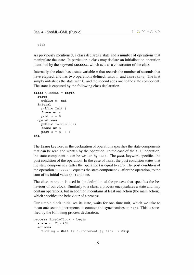
As previously mentioned, a class declares a state and a number of operations thatmanipulate the state. In particular, a class may declare an initialisation operationidentified by the keyword initial, which acts as a constructor of the class.
Internally, the clock has a state variable s that records the number of seconds thathave elapsed, and has two operations defined: Init() and increment. The firstsimply initialises the state with 0, and the second adds one to the state component.The state is captured by the following class declaration.
class ClockSt = beginstate
public s: natinitial
public Init()frame wr spost s = 0
operationspublic increment()frame wr spost s = s~ + 1
end
The frame keyword in the declaration of operations specifies the state componentsthat can be read and written by the operation. In the case of the Init operation,the state component s can be written by Init. The post keyword specifies thepost condition of the operation. In the case of Init, the post condition states thatthe state component s (after the operation) is equal to zero. The post condition ofthe operation increment equates the state component s, after the operation, to thesum of its initial value (s~) and one.
The class ClockSt is used in the definition of the process that specifies the be-haviour of our clock. Similarly to a class, a process encapsulates a state and maycontain operations, but in addition it contains at least one action (the main action),which specifies the behaviour of a process.
Our simple clock initialises its state, waits for one time unit, which we take tomean one second, increments its counter and synchronises on tick. This is spec-ified by the following process declaration.
process SimpleClock = beginstate c: ClockStactions
Ticking = Wait 1; c.increment(); tick -> Skip
15
D22.4 - SysML–CML (Public)
@ c.Init(); mu X @ Ticking; Xend
The simple clock is a process that declares a state and a number of actions. Thestate, in this case, is formed by a single state component c of type ClockSt. Theactions include Ticking and the action started by @. It simply initialises the stateby calling the operation Init() of the state component c and recursively (mu) callsthe action Ticking. This action waits for one time unit (Wait 1), increments theinternal counter and synchronises on the channel tick.
Our initial specification of the clock is extremely simple; the only observableevent is the synchronisation on tick. It might be interesting to have a clock thattakes advantage of its internal counter and supplies information about how manyseconds, minutes, hours and days have elapsed.
We now extend our simple clock to include this additional functionality. First,we declare four additional channels that communicate a natural number. They areused to query the seconds, minutes, hours and days that have elapsed.
channelssecond, minute, hour, day: nat
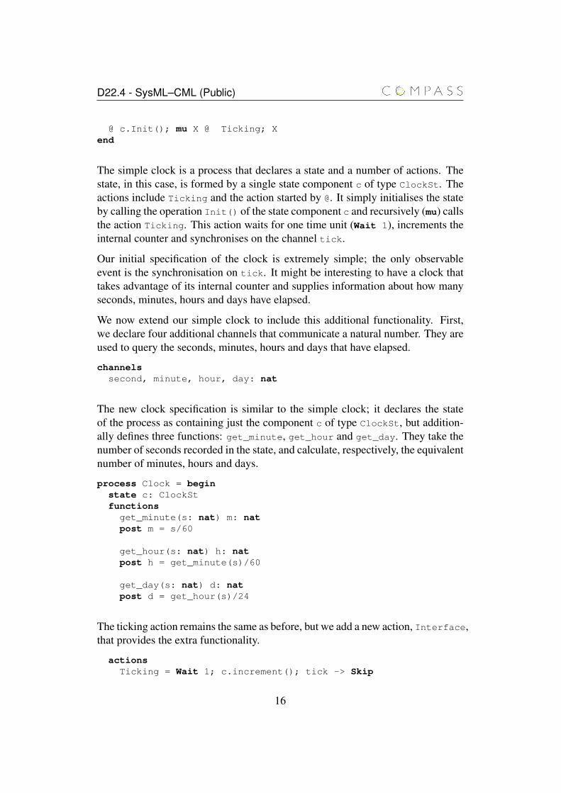
The new clock specification is similar to the simple clock; it declares the stateof the process as containing just the component c of type ClockSt, but addition-ally defines three functions: get_minute, get_hour and get_day. They take thenumber of seconds recorded in the state, and calculate, respectively, the equivalentnumber of minutes, hours and days.
process Clock = beginstate c: ClockStfunctions
get_minute(s: nat) m: natpost m = s/60
get_hour(s: nat) h: natpost h = get_minute(s)/60
get_day(s: nat) d: natpost d = get_hour(s)/24
The ticking action remains the same as before, but we add a new action, Interface,that provides the extra functionality.
actionsTicking = Wait 1; c.increment(); tick -> Skip
16
D22.4 - SysML–CML (Public)
Interface = second!(c.s) -> Interface[] minute!(get_minute(c.s)) -> Interface[] hour!(get_hour(c.s)) -> Interface[] day!(get_day(c.s)) -> Interface
This action simply offers an external choice ([]) of communication over the chan-nels second, minute, hour and day, and recurses. Each communication outputs(indicated by ! after a channel name) the appropriate value calculated using thefunctions previously defined.
Now, the main action of the new clock is slightly different. It first initialises thestate as before, but instead of offering Ticking alone, it composes Ticking inparallel with the recursive action Interface with the option of interrupting (/\)Interface with a synchronisation on tick. The operator A1[|ns1| cs |ns2|]A2
composes the actions A1 and A2 in parallel based on a set of events cs on whichthe two parallel actions synchronise, and two name sets ns1 and ns2 that partitionthe state of the process and indicate which state components can be updated bythe left (ns1) and right (ns2) parallel actions. In our example, the action Ticking
can update the state component c and the right parallel action does not update thestate. The parallel actions synchronise on the channel tick.
@ c.Init(); mu X @ (Ticking [|{c}|{|tick|}|{}|] (Interface/\tick -> Skip)
); Xend
While Ticking is waiting, the right hand side of the parallelism can offer anynumber of interactions over the channels in Interface. When Ticking finisheswaiting, s is incremented, and the parallelism synchronises on tick. In this case,the action Interface is interrupted and both sides of the parallelism terminate.At this point, the recursive call (on X) takes place.
When the parallelism starts, both parallel actions take a copy of the state, and whenthe parallelism terminates, the state is updated based on the changes performed bythe two parallel actions (on their copies of the state) and the partition of the state.A consequence of this is that changes to the state performed by Ticking can onlybe reflected on the behaviour of Interface when the parallelism terminates, thestate is updated and Interface restarts (as part of the recursive call) with a copyof the updated state.
Now we have a clock that not only signals the passing of time, but can also outputthe time. However, we might also want to be able to restart the clock. For this, we
17

D22.4 - SysML–CML (Public)
define a channel restart and a new clock RestartableClock.
channelsrestart
The definition of the restartable clock is similar to that of the process Clock de-fined above. The process RestartableClock has a new action Cycle, and itsmain action offers the action Cycle and the possibility of interrupting it throughthe channel restart. If the interruption takes place, the main action recurses andCycle is called resetting the state.
process RestartableClock = beginstate c: ClockStfunctions
get_minute(s: nat) m: natpost m = s/60
get_hour(s: nat) h: natpost h = get_minute(s)/60
get_day(s: nat) d: natpost d = get_hour(s)/24
actionsTicking = Wait 1; c.increment(); tick -> Skip
Interface = second!(c.s) -> Interface[] minute!(get_minute(c.s)) -> Interface[] hour!(get_hour(c.s)) -> Interface[] day!(get_day(c.s)) -> Interface
Cycle = c.Init(); mu X @ (Ticking [|{c}|{|tick|}|{}|] (Interface/\tick -> Skip)
); X
@ mu X @ Cycle /\ restart -> Xend
We can further extend the functionality of the clock by specifying a multi- clock.A simple way of defining such a clock is to compose a number of restartableclocks (or any other variety of clock). This raises the question of how the clocksare composed. For instance, do all clocks synchronise on tick? Can they berestarted on a one by one basis? We present below two processes that model amulti-clock. Both of them assume that the clocks are synchronous, but the firstallows independent restarting, while the second does not.
First, we define the channels that allow the environment to communicate with
18
D22.4 - SysML–CML (Public)
specific clocks. We assume that the clocks in the multi-clock are indexed usingnatural numbers, and are similar to those already defined, communicating a naturalnumber (the identifier of the clock) and the value originally communicated. Weprefix the name of the new channels with an i.
channelsisecond, iminute, ihour, iday: nat * natirestart: nat
Our first model of a multi-clock is specified by the process NRestartableClocks1.This is a parametrised process that takes the number n of clocks, and starts n
copies of RestartableClock running in parallel and synchronising on tick. Thechannels in the RestartableClock process need to be renamed to distinguish oneclock from another. We rename each channel (except tick) to its i version.
process NRestartableClocks1 = n: nat @[|{|tick|}|] i: {1,...,n} @
RestartableClock[[second <- isecond.i,minute <- iminute.i,hour <- ihour.i,day <- iday.i,restart <- irestart.i]]
Our alternative process NRestartableClocks2 is similar, except that the differentclocks synchronise on restart as well, and this channel is not renamed. Thus, asynchronisation on restart restarts all the clocks simultaneously.
process NRestartableClocks2 = n: nat @[|{|tick, restart|}|] i: {1,...,n} @
RestartableClock[[second <- isecond.i,minute <- iminute.i,hour <- ihour.i,day <- iday.i]]
One might consider that, whilst these definitions are reasonably intuitive, they arenot the most efficient for implementation purposes. So, one might implement amulti-clock with a single clock that provides all services on the i channels. Tomodel this design, we simply associate each channel of a restartable clock withthe equivalent i channel, but ranging over all the possible clocks.
process NRestartableClocksImpl = n: nat @RestartableClock[[second <- isecond.i,
minute <- iminute.i,hour <- ihour.i,day <- iday.i | i in set {1,...,n}]]
19
D22.4 - SysML–CML (Public)
This process simply renames each channel of RestartableClock (except tickand restart) to a set of communications on the associated i channel communi-cating the identifiers of the clocks.
This process raises the question of which of our multi-clock processes is beingimplemented by NRestartableClocksImpl. These questions can be formulatedas follows.
assert NRestartableClocks1 [= NRestartableClocksImplassert NRestartableClocks2 [= NRestartableClocksImpl
The first assertion states that the process NRestartableClocksImpl is a refine-ment of the process NRestartableClocks1, and the second asserts that the im-plementation is a refinement of NRestartableClocks2. For some models, thisassertions can be checked using a model-checker, but for others, a theorem-provermay be necessary. The CML tools will help answer such questions.
More details about the CML notation will be presented as needed in the se-quel.
2.2 SysML
SysML, standardised by the Object Management Group [Obj10a], is a modellingnotation for systems engineering, defined as a UML 2.0 profile. SysML allows therepresentation of systems, hardware, software, information and processes, withthe objective of providing dedicated support for system-level modelling, verifica-tion and validation. Like UML, SysML provides a number of diagrams to supportthe description of different aspects of a system. SysML has the following promi-nent distinctive features that are not present in UML:
• The “classical” software-centric focus present in UML, through class di-agrams and composite structure diagrams, has been moved to the system-level in SysML by the introduction of block definition diagrams and internalblock diagrams [Obj10a, Chapter 8].
• The UML notion of interfaces has been focused in SysML on system-levelinterfaces by the introduction of service-based and flow-based ports andinterfaces [Obj10a, Chapter 9].
• The general UML notion of constraints has been strengthened in SysMLthrough the introduction of constraint blocks and parametric diagrams [Obj10a,Chapter 10].
20
D22.4 - SysML–CML (Public)
• SysML introduces a notation for requirements engineering and tracing frommodel elements to requirements [Obj10a, Chapter 16].
An overview of SysML, in the context of SoS architectural modelling in COM-PASS, is provided by Holt et al. [HNH+12]. In this section, we shall brieflydescribe the parts of SysML structural and behavioural diagrams that are relevantin the context of the translation to CML.
Block Definition Diagram
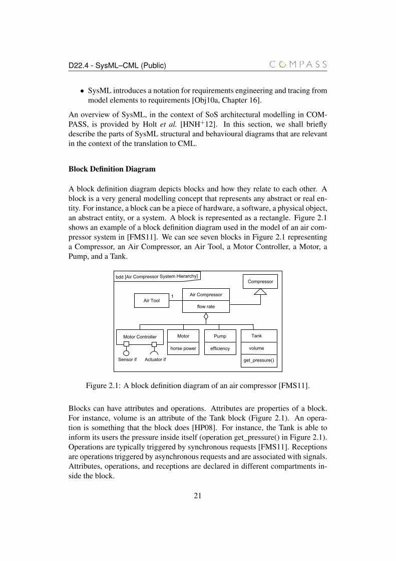
A block definition diagram depicts blocks and how they relate to each other. Ablock is a very general modelling concept that represents any abstract or real en-tity. For instance, a block can be a piece of hardware, a software, a physical object,an abstract entity, or a system. A block is represented as a rectangle. Figure 2.1shows an example of a block definition diagram used in the model of an air com-pressor system in [FMS11]. We can see seven blocks in Figure 2.1 representinga Compressor, an Air Compressor, an Air Tool, a Motor Controller, a Motor, aPump, and a Tank.
bdd [Air Compressor System Hierarchy]
flow rate
Motor Controller Motor Pump Tank
horse power efficiency volume
Air Compressor
get_pressure()Sensor if Actuator if
Air Tool1
Compressor
Figure 2.1: A block definition diagram of an air compressor [FMS11].
Blocks can have attributes and operations. Attributes are properties of a block.For instance, volume is an attribute of the Tank block (Figure 2.1). An opera-tion is something that the block does [HP08]. For instance, the Tank is able toinform its users the pressure inside itself (operation get_pressure() in Figure 2.1).Operations are typically triggered by synchronous requests [FMS11]. Receptionsare operations triggered by asynchronous requests and are associated with signals.Attributes, operations, and receptions are declared in different compartments in-side the block.
21
D22.4 - SysML–CML (Public)
We define that a block is related to another block by connecting them with anassociation. Associations are represented graphically as a solid line connectingthe blocks. Associations can have names and can relate blocks over differentmultiplicities. For instance, the Air Compressor block is associated with one AirTool block in Figure 2.1.
A different way to relate blocks is via the aggregation operator. The aggregationsays that a block is made up of other blocks [HP08]. The aggregation is depictedas diamond in block definition diagrams. Figure 2.1 shows that an Air Compressoris made up of a Motor Controller, a Motor, a Pump, and a Tank.
Composition is a whole-part relation in which the parts cannot exist by them-selves, as it is an inherent part of the whole. For instance, a Student is composedof a block Schedule. If the Student is removed, so is Schedule. The lifetime of theparts is dependent on the lifetime of the whole. Composition is represented by afilled diamond.
We can define ports for a block, which are interaction points from which a blockcommunicates to its environment. A port is usually associated with an interface,which can be either provided or required. If a block takes inputs from an interfaceand acts on that input, that interface is a provided interface [HP08]. If a blockgenerates outputs to be used by another block, that is a required interface [HP08].Ports are depicted as a small rectangles attached to the edges of a block. Requiredinterfaces resemble semi-circles, while provided interfaces are represented by cir-cles. Figure 2.1 shows that the Motor Controller provides an interface to a Sensorand requires an interface from an Actuator.
Blocks can be declared as being a particular type of another block. For instance,the Air Compressor is defined as a type of Compressor. Compressor in Figure 2.1has all the features shared by any compressor. And Air Compressor just inheritsthose features. Generalisations like this are represented graphically by an arrowhead pointing from the specialised block towards the general block.
Internal Block Diagram
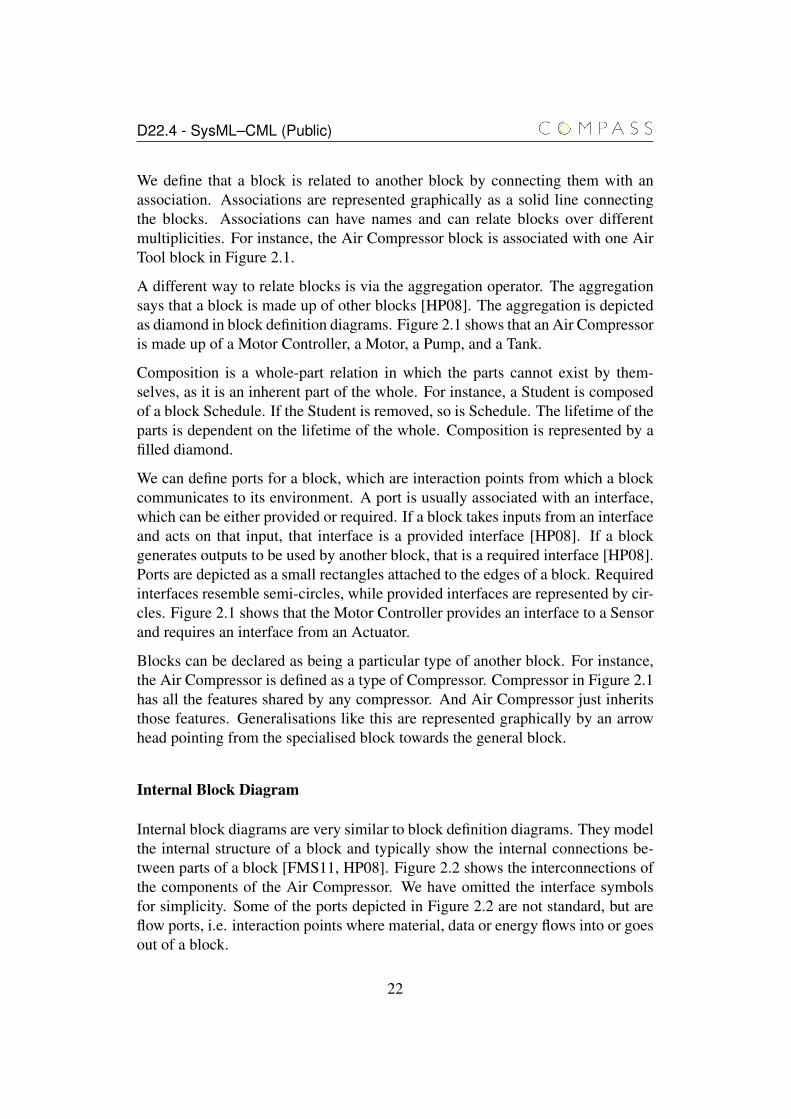
Internal block diagrams are very similar to block definition diagrams. They modelthe internal structure of a block and typically show the internal connections be-tween parts of a block [FMS11, HP08]. Figure 2.2 shows the interconnections ofthe components of the Air Compressor. We have omitted the interface symbolsfor simplicity. Some of the ports depicted in Figure 2.2 are not standard, but areflow ports, i.e. interaction points where material, data or energy flows into or goesout of a block.
22
D22.4 - SysML–CML (Public)
ibd [Air Compressor]
: Motor : Motor Controller
: Tank: Pump
torque out if
torque in if
control in if
control out if
air in if
air out if
air out if
air out if
pressure out if
pressure in if
air in ifair in if
Figure 2.2: An internal block diagram of the air compressor [FMS11].
State Machine Diagram
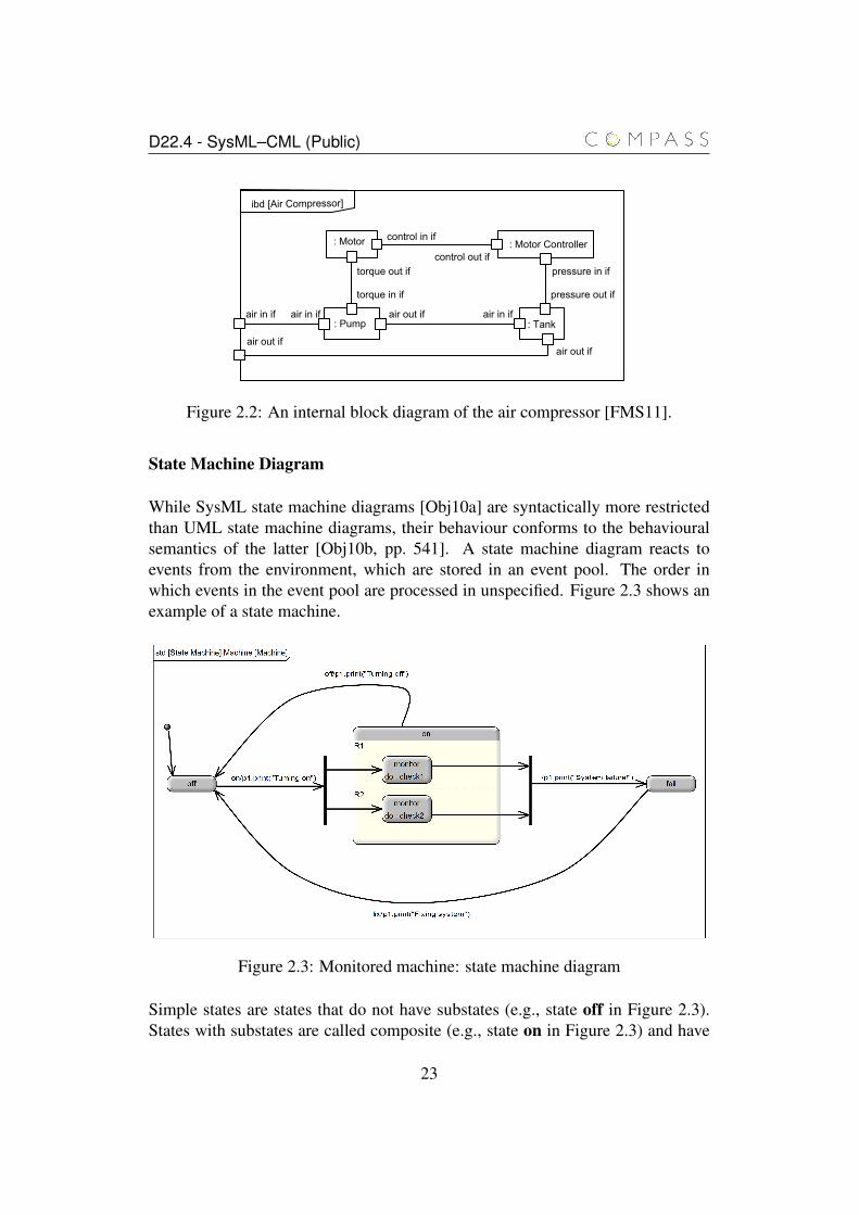
While SysML state machine diagrams [Obj10a] are syntactically more restrictedthan UML state machine diagrams, their behaviour conforms to the behaviouralsemantics of the latter [Obj10b, pp. 541]. A state machine diagram reacts toevents from the environment, which are stored in an event pool. The order inwhich events in the event pool are processed in unspecified. Figure 2.3 shows anexample of a state machine.
Figure 2.3: Monitored machine: state machine diagram
Simple states are states that do not have substates (e.g., state off in Figure 2.3).States with substates are called composite (e.g., state on in Figure 2.3) and have
23

D22.4 - SysML–CML (Public)
one or more regions (e.g., region R1 in state on in Figure 2.3) that group itssubstates. A composite state with two or more regions is called an orthogonalstate, and we refer to composite states with a single region as non-orthogonalstates. Multiple regions of a composite state are visualised by dashed lines thatpartition the inside of the state, and all regions of a state are active when the stateis active, and vice-versa. Each region contains a number of substates, and whenthe region is active, only one of its substates can be active.
State may contain three types of behaviour: entry and exit actions, and “do activi-ties” (e.g, the activity check1 in Figure 2.3). Entry actions are executed when thestate is entered, exit actions are executed when the state is exited, and “do activ-ities” are executed when the state becomes active. “Do activities” may continueindefinitely and may be interrupted by a transition that exits the state.
When entering a non-orthogonal composite state or a region, the decision of whichsubstate to enter can be specified by initial pseudostates or history pseudostates.Initial pseudostates (represented graphically by solid black circles as shown inFigure 2.3) provide a transition path (that is, a sequence of transitions connectedby pseudo state) to the state that must be entered.
A history pseudostate records the most recently entered substate of the state or re-gion that contains it. When the state or region containing the history pseudostateis entered, the last active substate is entered; it is represented graphically by a cir-cle with a capital letter H inside. There are two variants of history pseudostates,shallow history, which affects only the state or region containing the history pseu-dostate, and deep history, which affects the state or region containing it and all ofits substates and subregions. Deep history pseudostates are represented as shallowhistory pseudostates with an asterisk next to the H.
The connection between the initial pseudostate and the substates of its parent isspecified by transitions. In general, transitions connect source and target vertices(states or pseudostates), and may contain a trigger, guard and behaviour. Thetransition from the state off to the state on in Figure 2.3 is triggered by a signal off,and has a behaviour p1.print("Turning off"). For the purpose of thiswork we divide transitions between completion and non-completion transitions.Completion transitions are triggerless transitions leaving a state that are executedwhen the internal behaviour of the state (“do activities” and substates) terminates.Non-completion transitions are triggered by events from the event pool and caninterrupt the internal events of the its source states.
A transition between two states, whose trigger and guard (if any) are evaluated totrue, can be executed (provided it does not conflict with transitions with higherpriorities) by exiting the source state, executing the transition behaviour and en-
24
D22.4 - SysML–CML (Public)
tering the target state. In the general case, transitions can cross state boundaries;this requires that not only the source state is exited by the transition, but some ofits ancestors too. The highest level states that must be exited as a result of a tran-sition are the substates of the least common ancestor of the source and destinationof the transition.
Two or more transitions can be connected by junction pseudostates (representedgraphically by a solid black circle) to form a transition path that essentially be-haves as a transition with multiple source and target states. A junction pseudostateprovides a mechanism for choosing which transition (leaving the junction pseu-dostate) to follow. Transitions leaving junction pseudostates cannot have triggers,and the evaluation of the guard is performed prior to the execution of the tran-sition. An alternative is the choice pseudostate that provides a mechanism forchoosing the particular transitions to follow, but, unlike junction pseudostates, thedecision of which transition to follow is performed during the execution of thetransition path. Therefore, the execution of the behaviours of the transitions in thepath can affect the outcome of the execution of the choice pseudostate.
A non-orthogonal composite state (that is, a composite state with a single region)or a region may contain a final state. When reached, the final state indicates thatthe internal behaviour of the composite state or region has terminated. In conjunc-tion with the termination of the “do activities”, this can trigger the execution ofcompletion transitions.
Finally, state machines may contain join and fork pseudostates. Join pseudostates(e.g., right vertical bar in Figure 2.3) provide a way of gathering transitions leavingregions of an orthogonal composite state and joining them into one single transi-tion targeting a state (outside the composite state). The transitions associated witha join pseudostate are enabled when all transitions reaching it are. When fired,all the source states are exited, and the target state is entered. A fork pseudostate(e.g., left vertical bar in Figure 2.3) behaves in the opposite direction; it links asingle state to states in orthogonal regions. When the transition reaching the forkpseudostate is executed, all target states are entered.
Sequence Diagram
In UML 2.0, there are four types of diagram to describe interactions: sequencediagrams, communications diagrams, interaction overview diagrams, and tim-ing diagrams. Among them, the sequence diagram is the most commonly usedto describe interaction aspects of systems, and therefore SysML considers onlysequence diagrams to describe interactions. According to the SysML specifica-
25
D22.4 - SysML–CML (Public)
tion [Obj10a], communications diagram and interaction overview diagrams areexcluded as they overlap in functionality without adding significant capabilitiesfor modelling systems. Timing diagrams are not included because of its maturityand suitability for Systems Engineering needs.
The main purpose of sequence diagrams is to describe operational scenarios ofa system with an emphasis on time [HP08]. This concept is introduced throughthe use of an element known as a lifeline. Each participant of the diagram (typ-ically a block) possesses a lifeline where we can represent a message exchangeordering.
Messages can be of three types: asynchronous (open arrow), call (synchronous- closed arrow), or reply from a call (dashed arrow). They are used to representa communication from one participant to another. SysML also has available acollection of operators like the parallel composition, the conditional, the loop, etc.called combined fragments.
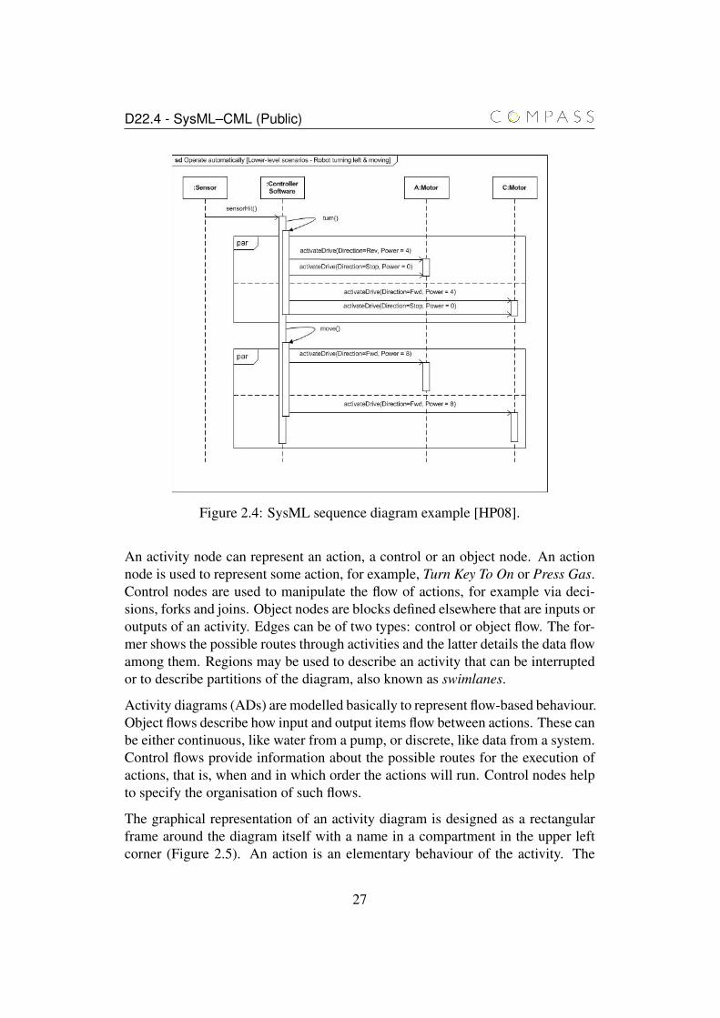
Figure 2.4 presents an example in [HP08] where the scenario being described isthe movement of a robot. There are four lifelines (Sensor, Controller Software,Motor A and Motor C), nine messages exchanged between them, and two PARcombined fragments denoting parallel behaviour. For example, sensorHit() is anasynchronous message going from the Sensor to the Controller Software, andturn() is a synchronous message going from the Controller Software to itself. TheSensor sends a message to the Controller Software, which in turn, sends a turn()message to itself. Then, the Controller Software sends two messages in sequenceto Motor A and two messages in sequence to Motor C. This transmission happensin parallel (see the PAR combined fragment on top). Finally, the message move()is sent from the Controller Software to itself, which in turn, sends two messagesin parallel: one to Motor A, and another to Motor C.
Whilst SysML sequence diagrams have a rich syntax, in Chapter 6, we detail thekey elements relating to the initial set of translation rules.
Activity Diagram
The SysML activity diagram is imported from UML 2.0 with some extensions.This type of diagram is based on classic flow charts. According to Holt andPerry [HP08], activity diagrams can be used for low-level modelling in compar-ison to the previous diagrams. Their main utility is to detail the behaviour of anoperation, although other uses include describing workflows or processes.
An activity diagram has three basic elements: activity nodes, edges and regions.
26
D22.4 - SysML–CML (Public)
Figure 2.4: SysML sequence diagram example [HP08].
An activity node can represent an action, a control or an object node. An actionnode is used to represent some action, for example, Turn Key To On or Press Gas.Control nodes are used to manipulate the flow of actions, for example via deci-sions, forks and joins. Object nodes are blocks defined elsewhere that are inputs oroutputs of an activity. Edges can be of two types: control or object flow. The for-mer shows the possible routes through activities and the latter details the data flowamong them. Regions may be used to describe an activity that can be interruptedor to describe partitions of the diagram, also known as swimlanes.
Activity diagrams (ADs) are modelled basically to represent flow-based behaviour.Object flows describe how input and output items flow between actions. These canbe either continuous, like water from a pump, or discrete, like data from a system.Control flows provide information about the possible routes for the execution ofactions, that is, when and in which order the actions will run. Control nodes helpto specify the organisation of such flows.
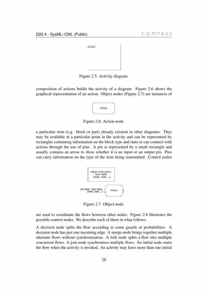
The graphical representation of an activity diagram is designed as a rectangularframe around the diagram itself with a name in a compartment in the upper leftcorner (Figure 2.5). An action is an elementary behaviour of the activity. The
27
D22.4 - SysML–CML (Public)
Figure 2.5: Activity diagram.
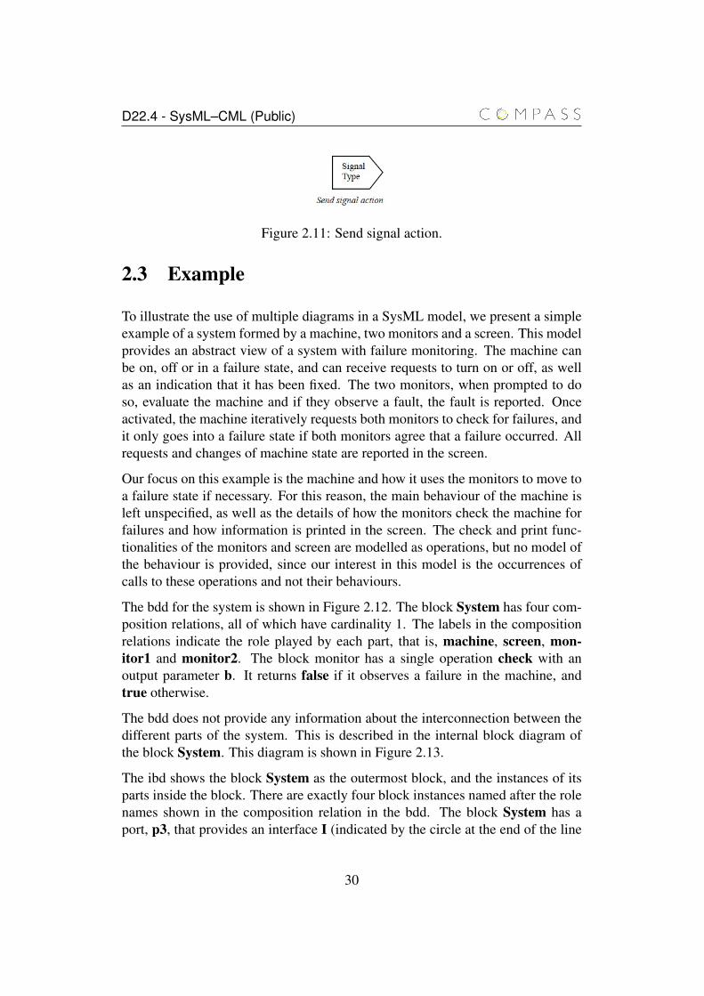
composition of actions builds the activity of a diagram. Figure 2.6 shows thegraphical representation of an action. Object nodes (Figure 2.7) are instances of
Figure 2.6: Action node.
a particular item (e.g. block or part) already existent in other diagrams. Theymay be available at a particular point in the activity and can be represented byrectangles containing information on the block type and state or can connect withactions through the use of pins. A pin is represented by a small rectangle andusually contains an arrow to show whether it is an input or an output pin. Pinscan carry information on the type of the item being transmitted. Control nodes
Figure 2.7: Object node.
are used to coordinate the flows between other nodes. Figure 2.8 illustrates thepossible control nodes. We describe each of them in what follows.
A decision node splits the flow according to some guards or probabilities. Adecision node has just one incoming edge. A merge node brings together multiplealternate flows without synchronisation. A fork node splits a flow into multipleconcurrent flows. A join node synchronises multiple flows. An initial node startsthe flow when the activity is invoked. An activity may have more than one initial
28

D22.4 - SysML–CML (Public)
Figure 2.8: Control nodes.
(a) Control flow. (b) Object flow.
Figure 2.9: Activity edges.
node, then invoking an activity starts multiple flows. An activity may have morethan one activity final node. The first final node reached stops all flows in theactivity. A flow final node destroys all tokens that arrive at it. It has no effect onother flows in the activity.
An activity edge may be of two types: control flow or object flow. The formercontrols the order in which the actions may occur and no information of an objectnode pass through a control flow edge. The latter is the opposite, as it is used torepresent the flow of information through activity nodes. Figure 2.9 shows thegraphical syntax of control flows (Figure 2.9(a)) and object flows (Figure 2.9(b)).An accept event action is an action that waits for the occurrence of an event meet-ing a specified condition. Figure 2.10 displays the representation of an acceptevent action. A send signal action creates a signal instance from its inputs, and
Figure 2.10: Accept event action.
transmits it to the target object, starting the execution of an activity. Send signalactions are represented by a convex pentagon as shown in Figure 2.11.
In the next section, we present an example that illustrates the use of all diagramswe have described above.
29
D22.4 - SysML–CML (Public)
Figure 2.11: Send signal action.
2.3 Example
To illustrate the use of multiple diagrams in a SysML model, we present a simpleexample of a system formed by a machine, two monitors and a screen. This modelprovides an abstract view of a system with failure monitoring. The machine canbe on, off or in a failure state, and can receive requests to turn on or off, as wellas an indication that it has been fixed. The two monitors, when prompted to doso, evaluate the machine and if they observe a fault, the fault is reported. Onceactivated, the machine iteratively requests both monitors to check for failures, andit only goes into a failure state if both monitors agree that a failure occurred. Allrequests and changes of machine state are reported in the screen.
Our focus on this example is the machine and how it uses the monitors to move toa failure state if necessary. For this reason, the main behaviour of the machine isleft unspecified, as well as the details of how the monitors check the machine forfailures and how information is printed in the screen. The check and print func-tionalities of the monitors and screen are modelled as operations, but no model ofthe behaviour is provided, since our interest in this model is the occurrences ofcalls to these operations and not their behaviours.
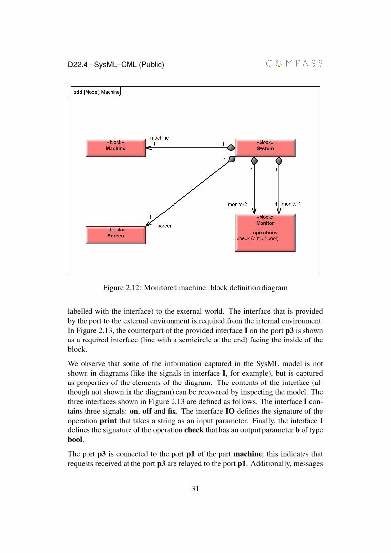
The bdd for the system is shown in Figure 2.12. The block System has four com-position relations, all of which have cardinality 1. The labels in the compositionrelations indicate the role played by each part, that is, machine, screen, mon-itor1 and monitor2. The block monitor has a single operation check with anoutput parameter b. It returns false if it observes a failure in the machine, andtrue otherwise.
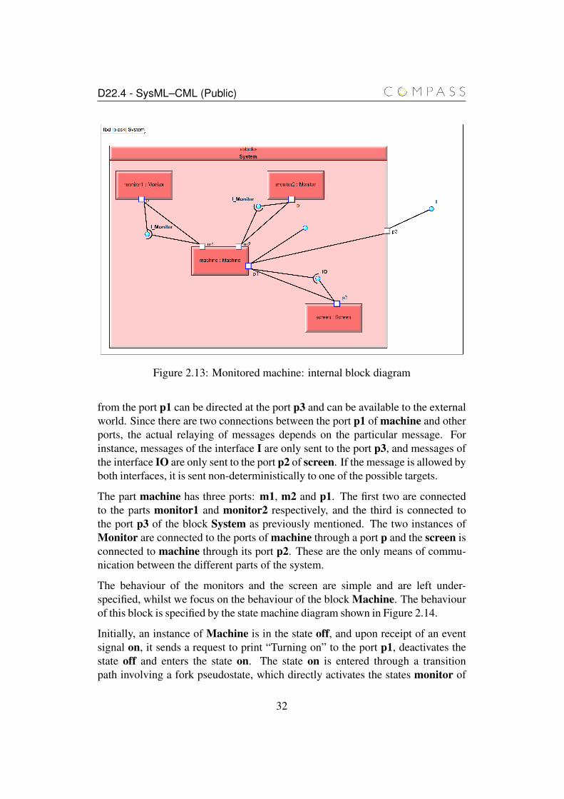
The bdd does not provide any information about the interconnection between thedifferent parts of the system. This is described in the internal block diagram ofthe block System. This diagram is shown in Figure 2.13.
The ibd shows the block System as the outermost block, and the instances of itsparts inside the block. There are exactly four block instances named after the rolenames shown in the composition relation in the bdd. The block System has aport, p3, that provides an interface I (indicated by the circle at the end of the line
30
D22.4 - SysML–CML (Public)
Figure 2.12: Monitored machine: block definition diagram
labelled with the interface) to the external world. The interface that is providedby the port to the external environment is required from the internal environment.In Figure 2.13, the counterpart of the provided interface I on the port p3 is shownas a required interface (line with a semicircle at the end) facing the inside of theblock.
We observe that some of the information captured in the SysML model is notshown in diagrams (like the signals in interface I, for example), but is capturedas properties of the elements of the diagram. The contents of the interface (al-though not shown in the diagram) can be recovered by inspecting the model. Thethree interfaces shown in Figure 2.13 are defined as follows. The interface I con-tains three signals: on, off and fix. The interface IO defines the signature of theoperation print that takes a string as an input parameter. Finally, the interface Idefines the signature of the operation check that has an output parameter b of typebool.
The port p3 is connected to the port p1 of the part machine; this indicates thatrequests received at the port p3 are relayed to the port p1. Additionally, messages
31
D22.4 - SysML–CML (Public)
Figure 2.13: Monitored machine: internal block diagram
from the port p1 can be directed at the port p3 and can be available to the externalworld. Since there are two connections between the port p1 of machine and otherports, the actual relaying of messages depends on the particular message. Forinstance, messages of the interface I are only sent to the port p3, and messages ofthe interface IO are only sent to the port p2 of screen. If the message is allowed byboth interfaces, it is sent non-deterministically to one of the possible targets.
The part machine has three ports: m1, m2 and p1. The first two are connectedto the parts monitor1 and monitor2 respectively, and the third is connected tothe port p3 of the block System as previously mentioned. The two instances ofMonitor are connected to the ports of machine through a port p and the screen isconnected to machine through its port p2. These are the only means of commu-nication between the different parts of the system.
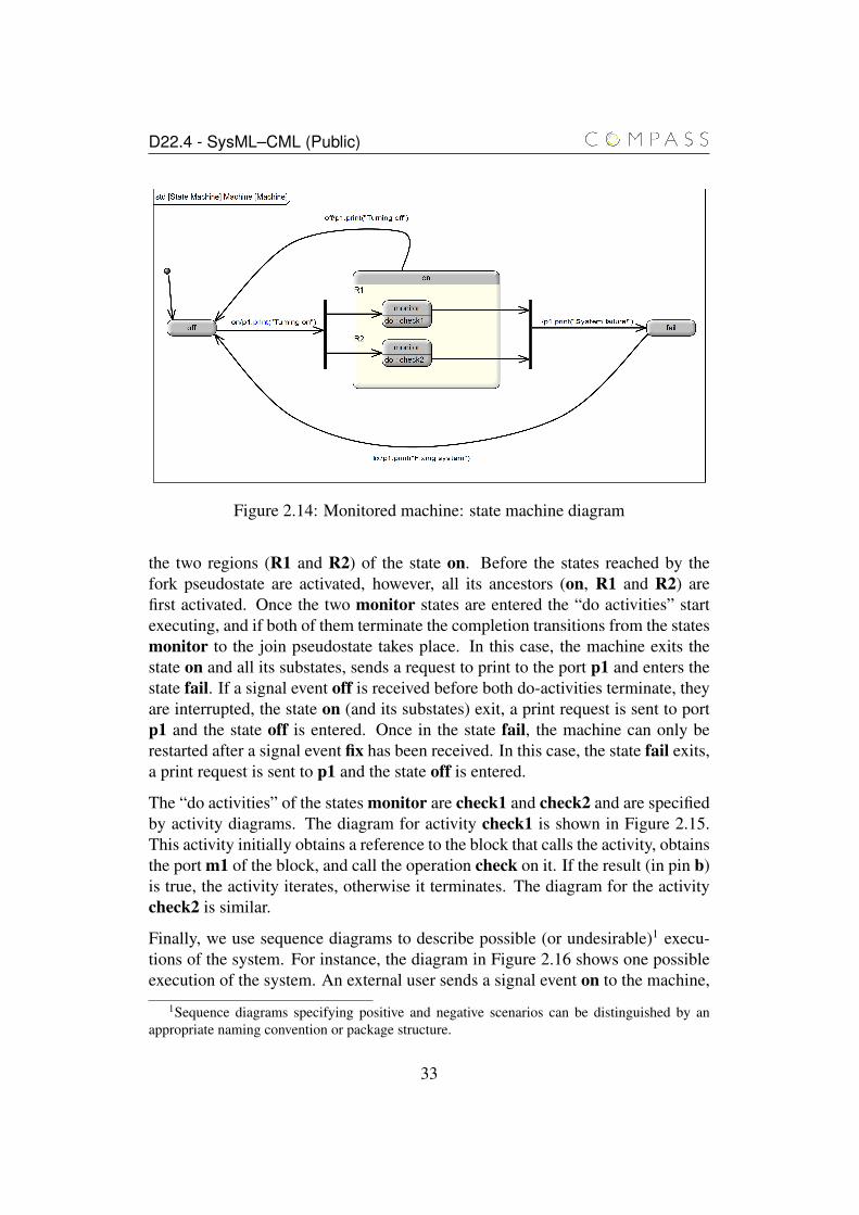
The behaviour of the monitors and the screen are simple and are left under-specified, whilst we focus on the behaviour of the block Machine. The behaviourof this block is specified by the state machine diagram shown in Figure 2.14.
Initially, an instance of Machine is in the state off, and upon receipt of an eventsignal on, it sends a request to print “Turning on” to the port p1, deactivates thestate off and enters the state on. The state on is entered through a transitionpath involving a fork pseudostate, which directly activates the states monitor of
32
D22.4 - SysML–CML (Public)
Figure 2.14: Monitored machine: state machine diagram
the two regions (R1 and R2) of the state on. Before the states reached by thefork pseudostate are activated, however, all its ancestors (on, R1 and R2) arefirst activated. Once the two monitor states are entered the “do activities” startexecuting, and if both of them terminate the completion transitions from the statesmonitor to the join pseudostate takes place. In this case, the machine exits thestate on and all its substates, sends a request to print to the port p1 and enters thestate fail. If a signal event off is received before both do-activities terminate, theyare interrupted, the state on (and its substates) exit, a print request is sent to portp1 and the state off is entered. Once in the state fail, the machine can only berestarted after a signal event fix has been received. In this case, the state fail exits,a print request is sent to p1 and the state off is entered.
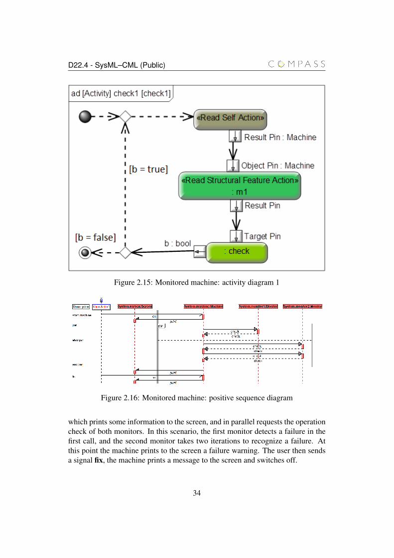
The “do activities” of the states monitor are check1 and check2 and are specifiedby activity diagrams. The diagram for activity check1 is shown in Figure 2.15.This activity initially obtains a reference to the block that calls the activity, obtainsthe port m1 of the block, and call the operation check on it. If the result (in pin b)is true, the activity iterates, otherwise it terminates. The diagram for the activitycheck2 is similar.
Finally, we use sequence diagrams to describe possible (or undesirable)1 execu-tions of the system. For instance, the diagram in Figure 2.16 shows one possibleexecution of the system. An external user sends a signal event on to the machine,
1Sequence diagrams specifying positive and negative scenarios can be distinguished by anappropriate naming convention or package structure.
33
D22.4 - SysML–CML (Public)
Figure 2.15: Monitored machine: activity diagram 1
Figure 2.16: Monitored machine: positive sequence diagram
which prints some information to the screen, and in parallel requests the operationcheck of both monitors. In this scenario, the first monitor detects a failure in thefirst call, and the second monitor takes two iterations to recognize a failure. Atthis point the machine prints to the screen a failure warning. The user then sendsa signal fix, the machine prints a message to the screen and switches off.
34
D22.4 - SysML–CML (Public)
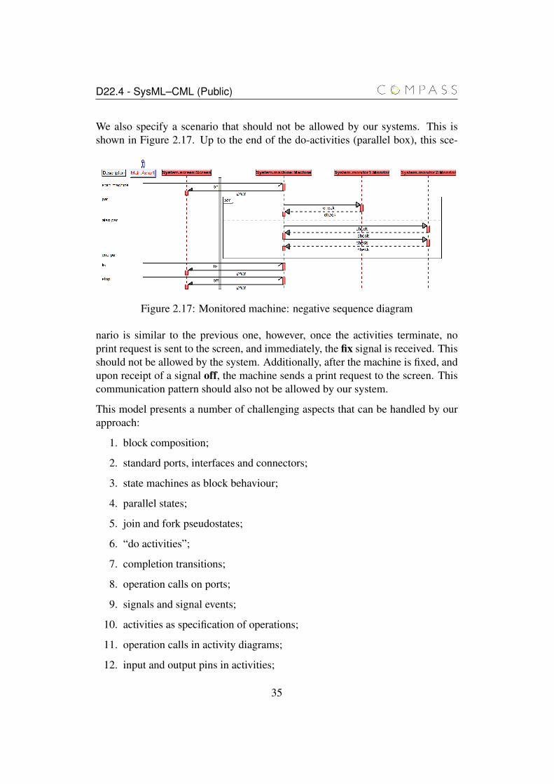
We also specify a scenario that should not be allowed by our systems. This isshown in Figure 2.17. Up to the end of the do-activities (parallel box), this sce-
Figure 2.17: Monitored machine: negative sequence diagram
nario is similar to the previous one, however, once the activities terminate, noprint request is sent to the screen, and immediately, the fix signal is received. Thisshould not be allowed by the system. Additionally, after the machine is fixed, andupon receipt of a signal off, the machine sends a print request to the screen. Thiscommunication pattern should also not be allowed by our system.
This model presents a number of challenging aspects that can be handled by ourapproach:
1. block composition;
2. standard ports, interfaces and connectors;
3. state machines as block behaviour;
4. parallel states;
5. join and fork pseudostates;
6. “do activities”;
7. completion transitions;
8. operation calls on ports;
9. signals and signal events;
10. activities as specification of operations;
11. operation calls in activity diagrams;
12. input and output pins in activities;
35
D22.4 - SysML–CML (Public)
13. sequence diagrams as scenario specifications;
14. synchronous and asynchronous messages; and
15. parallel fragments in sequence diagrams.
2.4 Final remarks
In this chapter we have given an overview of the two base notations of COMPASS:CML and SysML. We have illustrated CML by a simple example that illustratesthe modelling of a clock and the possible design choices available to the user. Fi-nally, we have presented a simple, yet comprehensive, SysML model that includesinstances of all diagrams covered by our semantics.
In the next chapter, we provide the foundations for the semantics of SysML mod-els. We describe the assumptions made about the models, the presentation styleused in describing the semantics, and the semantics of SysML models as a set ofblocks and diagrams.
36
Chapter 3
Formal semantics of SysMLmodels
In this chapter, we describe the assumptions made in defining the semantics ofSysML models. These assumptions take two forms: guidelines and meta-notation.The first acts upon the SysML models themselves, and establish what is requiredof a model for a CML model to be ascribed to it. The second specifies what is themeta-notation used in defining the translation rules that formalise the semanticsof SysML. The specification of the meta-notation is necessary to clarify what ispart of the CML model, and what is not.
In Section 3.1, we present the set of guidelines that allows us to provide a formalaccount of SysML. Section 3.2 describes the metalanguage used for presenting thetranslation rules that define the semantics of the diagrams. The chapter concludeswith Section 3.3 providing an overview of our strategy for the formalisation ofSysML models.
3.1 Guidelines
We identify here a subset of the SysML notation and describe guidelines of how itmust be used to allow us to define a semantics via a translation to CML. Our sub-set of SysML includes block definition diagrams, internal block diagrams, statemachine diagrams, activity diagrams and sequence diagrams. For block definitionand internal block diagrams, the following constructs are considered: blocks, op-erations, attributes, signals, ports, provided and required interfaces, associations,composition, generalisation.
37

D22.4 - SysML–CML (Public)
For state machine diagrams, the supported constructs are: simple and compositestates, regions, final states, initial and junction pseudostates, fork and merge pseu-dostates, transitions, and completion and deferred events. For activity diagrams,we have translation functions for: control nodes, actions without pins, actionswith input or output pin, accept and send signal actions, and object flow. Thecurrent semantics is restricted to synchronous communications. Finally, for se-quence diagrams the supported constructs are: lifelines, messages (synchronous,asynchronous and reply), message arguments, local attributes of the Interaction,CombinedFragments (PAR, STRICT, SEQ, ALT, OPT, BREAK, LOOP, CRITI-CAL), StateInvariant, InteractionUse and Gates.
Our guidelines of usage aim at supporting the definition of interesting cohesiveformal models of SysML models. The guidelines maximise the definedness ofa SysML model at both the entity definition level and at the instance definitionlevel. In this respect, they are similar to constraints imposed by most tools toenable automatic code generation from models.
A SysML model typically provides independent (although expected to be consis-tent) and disconnected views of an application (much like a set of classes in anobject-oriented program without a main class that coordinates all other classes).To generate a CML model (or indeed code), we need a connected model with anelement (typically a block) that identifies the application as a whole. Our guide-lines for maximal definedness at the entity definition level, however, still allow formodels that provide independent disconnected views. The guidelines for defined-ness at the instance level, therefore, require that enough information is availablein the SysML model to link models provided by the diagrams. Furthermore, theguidelines include three restrictions that simplify the semantics and make it moreamenable to automated reasoning.
Entity definition guidelines. They are as follows:
1. The body of each operation must be defined either by the block’s state ma-chine diagram, by a CML statement, or by an activity diagram;
2. In the graph of the composition relation, there must be exactly one con-nected component of size larger than 1, and this component must be a tree;
3. The blocks in the model must form a connected graph where the edges areeither generalisation or composition relations;
4. A composite block must not have attributes, operations, signals, activitiesor state machines;
38
D22.4 - SysML–CML (Public)
5. Associations in the block definition diagram must be matched in the internalblock diagram typed connectors;
6. Associations must be used in place of aggregation; and
7. Connectors between ports are not typed.
The first guideline contributes to the maximum definedness requirement by assur-ing that every operation is defined somewhere in the model. Whilst it is possible todefine the model of a block whose operations are not defined, such model wouldrepresent only the signature of the operations. Moreover, if an operation has areturn value, any possible values can be returned. This potentially restricts theeffectiveness of the formal reasoning supported by such models.
The second guideline guarantees that there is a root block of the model from whichthe semantics of the whole model can be defined, and the third guideline guaran-tees that all other blocks can be reached from a block in the model. We observethat this is essential to ensure that we have a connected model of the application,but it is not enough, since it is concerned only with block diagrams
The fourth guideline requires that a composite block is simply the compositionof its parts. The reason for this restriction is that it is not clear what it means fora composition of blocks to have an associated behaviour (in the form of a statemachine, for instance). We envisage two possible interpretations: (1) the statemachine is a specification of the desired behaviour of the composition of the parts,or (2) the state machine specifies a behaviour that is specific to the compositeblock and must be executed in parallel with the parts of the block.
If the second interpretation is the intention, it is possible to write a model thatcaptures this behaviour and follows our guidelines. We need to create a new partand move all components of the composite block to the new part. In this case, itwould be possible to adequately specify the dependencies between the behavioursin the new part with respect to the original parts.
Whilst operations and signals are not allowed in the composite block, ports aresupported and operations and signals on the ports are allowed. This restrictionforces the user to indicate, through the use of connectors and interfaces, whichparts treat which requests received at the ports of the composite block.
The fifth and sixth guidelines enforce our view that whilst composition is a relationbetween blocks, aggregation and association are relations between instances. Werequire that associations are used instead of aggregation, and that associations arematched by connectors at the instance level.
39

D22.4 - SysML–CML (Public)
Our view is motivated by the fact that composition entails uniqueness in the sensethat the same instance cannot be part of two different blocks, and therefore thesemantics of the parent block is directly defined in terms of the sub-blocks. More-over, since the instances of the sub-blocks that compose an instance of the parentblock are unique, we do not require any additional information to instantiate themas long as we can guarantee that they are unique.
Aggregation and association on the other hand allow sharing of blocks, and with-out the uniqueness assumption, we require additional information to determinewhether instances are shared and how. Since block definition diagrams cannotrefer to particular instances, any aggregation or association present in the blockdefinition diagram must be further specified in the internal block diagram to pro-vide this information. For associations, a connector in the internal block diagrammust be typed by an association in the block definition diagram. In the case of ag-gregation, the same approach is not possible because connectors cannot be typedby aggregations. For this reason, our guidelines do not allow the use of aggrega-tion.
Finally, since ports are not shown in block definition diagrams, connectors whereat least one end is a port cannot be typed by associations.
Instance-level guidelines. They are as follows:
1. Each composition head must specify the connections between its parts throughan internal block diagram.
2. All blocks in a composition whose minimum cardinality is larger than 0must appear in the internal block diagram of the containing block in num-bers compatible with their multiplicities.
3. The cardinalities that appear in an internal block diagram must be constants.
4. Ports may only be connected to other ports.
The internal block diagram specifies exactly which instances are present in a par-ticular realisation of the system, and exactly how they are associated (or not). Thisis enforced by the first three guidelines above.
The last guideline is necessary because a connector starting in a part (not a port)must correspond to an association of the part, which in turn must appear in theblock definition diagram. Since in the COMPASS SysML tool ports cannot beshown in block definition diagrams, the association cannot be between a port anda block, and therefore the connector typed by that association cannot link a port
40
D22.4 - SysML–CML (Public)
and a part. In this case, restriction 4 above is simply a consequence of the entity-level restriction 5.
Action language assumptions. Since the action language of SysML is not de-fined, we adopt a subset of CML. SysML operations and actions may be definedusing CML statements, that is, they may contain the same constructs used in CMLoperation definitions. No reactive behaviour is allowed, though. This is becausethe SysML paradigm is not based on the use of channels for communications, likeCML. Instead, attributes and operations of a block define the services providedby an application to its users. SysML operations are, therefore, data operationsthat explain how the state embedded in blocks and other operations can be used tospecify the service.
In the context of state machine diagrams, we extend the subset of CML used asaction language to include the following constructs:
Block operation call without return value Op(p1,...,p2)
Block operation call with return value v := Op(p1,...,p2)
return statement return v
Whilst the syntax of these constructs is similar to the syntax of CML, their seman-tics is not that of CML. The return statement is only allowed in transition actionstriggered by a call event. This restriction is necessary because the return statementis part of the definition of an operation, and as such must be associated with anoperation definition. For state machine diagrams, this is the case only for actionstriggered by a call event.
Simplification assumptions. The only guidelines of usage whose purpose issolely to simplify the semantics are as follows:
1. Each block must either have an associated state machine diagram or no otherassociated diagram specifying its behaviour;
2. Sequence diagrams specify scenarios of interactions between blocks thatthe model must or must not allow;
3. Operation are always synchronous. Asynchronous operations should bemodelled by signals.
The first guideline establishes that the only valid form of restricting the behaviourof a block is by means of state machines. Essentially, this forbids the use of ac-tivity and sequence diagrams for the specification of the overall behaviour of a
41
D22.4 - SysML–CML (Public)
block. State machine diagrams are particularly well suited for this task, sincethey support deferred events (useful to model blocking behaviour) as well as callevents (useful to model operations). Moreover, there is a convention [FMS11]for modelling operations that return values (i.e., the return keyword) in a statemachine, and our semantic definition of state machine diagrams covers such con-vention.
The second guideline restricts the possible uses of sequence diagrams to scenariovalidation purposes. This use is consistent with various case studies and recom-mendations [FMS11]. Although sequence diagrams have been used for other pur-poses (e.g., operation definition), it is our view that the emphasis on interactionbetween blocks given by sequence diagrams makes them more suitable to modelsuch scenarios than, for instance, to model operation definition.
The final guidelines forbids the use of asynchronous operations. The reason forthis guideline is that asynchronous operations give rise to some unclarities. It isnot clear what is the intended meaning of an asynchronous operations with returnvalues, and the difference between asynchronous operations and signals. If anasynchronous operations is required, we suggest the use of signals as a replace-ment.
3.2 Semantic rules metalanguage
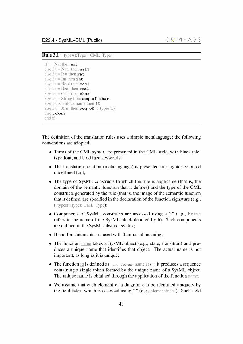
In this section, we outline the conventions used in the presentation of the transla-tion rules. For instance, Rule 3.1 takes SysML type and outputs CML type. Thefont differences emphasise the distinction between CML and the metalanguage.For instance, the underlined if statement, is not part of the generated CML mod-els, but the bold face nat may appear in the CML model as the translation of theSysML type Nat.
42
D22.4 - SysML–CML (Public)
Rule 3.1 t_types(t:Type): CML_Type =
if t = Nat then natelseif t = Nat1 then nat1elseif t = Rat then ratelseif t = Int then intelseif t = Bool then boolelseif t = Real then realelseif t = Char then charelseif t = String then seq of charelseif t is a block name then IDelseif t = X[n] then seq of t_types(x)else tokenend if
The definition of the translation rules uses a simple metalanguage; the followingconventions are adopted:
• Terms of the CML syntax are presented in the CML style, with black tele-type font, and bold face keywords;
• The translation notation (metalanguage) is presented in a lighter colouredunderlined font;
• The type of SysML constructs to which the rule is applicable (that is, thedomain of the semantic function that it defines) and the type of the CMLconstructs generated by the rule (that is, the image of the semantic functionthat it defines) are specified in the declaration of the function signature (e.g.,t_types(t:Type): CML_Type);
• Components of SysML constructs are accessed using a "." (e.g., b.namerefers to the name of the SysML block denoted by b). Such componentsare defined in the SysML abstract syntax;
• If and for statements are used with their usual meaning;
• The function name takes a SysML object (e.g., state, transition) and pro-duces a unique name that identifies that object. The actual name is notimportant, as long as it is unique;
• The function id is defined as [mk_token(name(s))]; it produces a sequencecontaining a single token formed by the unique name of a SysML object.The unique name is obtained through the application of the function name.
• We assume that each element of a diagram can be identified uniquely bythe field index, which is accessed using "." (e.g., element.index). Such field
43

D22.4 - SysML–CML (Public)
is important to differentiate two elements inside the same diagram, becausewe may have the case where elements exist with same name or signature.For the purpose of translations we assume that this field is a natural number,however, implementers may decide to use any type that fits the requirementto identify uniquely a element of the same diagram. In this latter case, isimportant to change the channel types where this field is used.
• The function set2seq(s) takes a set s and produces a sequence whose ele-ments are those of s;
• Lists whose separators are symbols of the CML syntax are defined by listconstructors. For instance, we have a constructor , , which takes a set ofterms and generates a comma-separated list of these terms. For example,
, {1,2,3} is the list 1,2,3 to be used, for instance, in a set enumeration.
The formalisation of the list constructors is simple and omitted here. We furtherexplain and illustrate its use as needed. All these operators of the metalanguageare identified by boxed symbols.
In the declaration of the translation function signatures, we define the constructof the CML abstract syntax [WCC+12] that characterises the range of the func-tion. For example, t_block_types(b:Block): class declaration takes a SysML block asparameter and defines a CML class.
We call each of the equations that define our translation function a translation rule.This reflects the fact that these definitions can be used as rewrite rules to generateCML models (automatically).
3.3 Overview of the semantics of SysML models
The domains of the translation functions are sets of SysML constructs and, asfar as possible, we have adhered to the metamodel of SysML presented in thestandards for both UML 2.0 and SysML. We do not adhere to the metamodel insituations where the necessary component is not directly available. For instance,we assume a block has a component stm which may contain a reference to thestate machine associated with the block.
As explained in the Section 3.1, we consider SysML models that contain a numberof connected blocks and associated behavioural diagrams defined in accordancewith our guidelines of usage. We also assume that the model has one or moreroot blocks. Under these assumptions, the semantics of a model is defined by
44
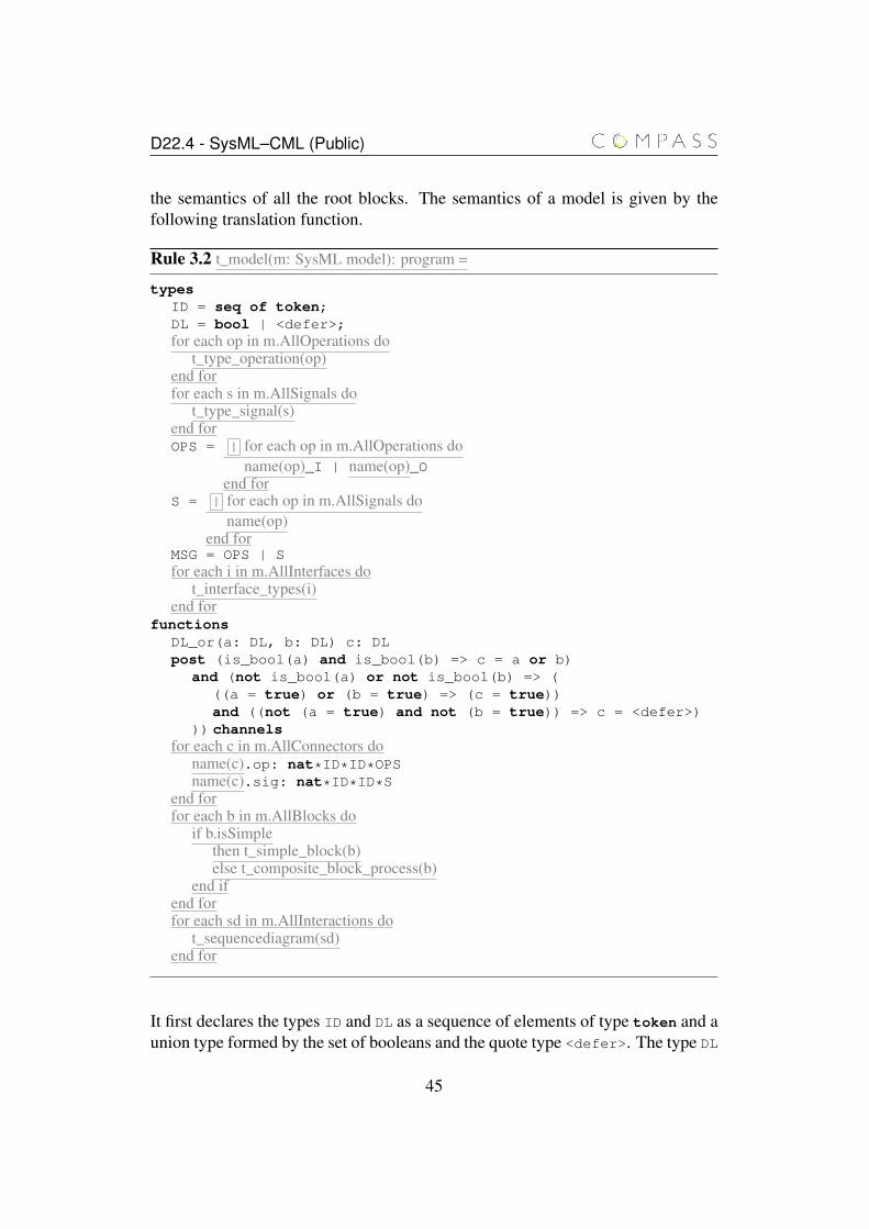
D22.4 - SysML–CML (Public)
the semantics of all the root blocks. The semantics of a model is given by thefollowing translation function.
Rule 3.2 t_model(m: SysML model): program =
typesID = seq of token;DL = bool | <defer>;for each op in m.AllOperations do
t_type_operation(op)end forfor each s in m.AllSignals do
t_type_signal(s)end forOPS = | for each op in m.AllOperations do
name(op)_I | name(op)_Oend for
S = | for each op in m.AllSignals doname(op)
end forMSG = OPS | Sfor each i in m.AllInterfaces do
t_interface_types(i)end for
functionsDL_or(a: DL, b: DL) c: DLpost (is_bool(a) and is_bool(b) => c = a or b)
and (not is_bool(a) or not is_bool(b) => (((a = true) or (b = true) => (c = true))and ((not (a = true) and not (b = true)) => c = <defer>)
)) channelsfor each c in m.AllConnectors do
name(c).op: nat*ID*ID*OPSname(c).sig: nat*ID*ID*S
end forfor each b in m.AllBlocks do
if b.isSimplethen t_simple_block(b)else t_composite_block_process(b)
end ifend forfor each sd in m.AllInteractions do
t_sequencediagram(sd)end for
It first declares the types ID and DL as a sequence of elements of type token and aunion type formed by the set of booleans and the quote type <defer>. The type DL
45
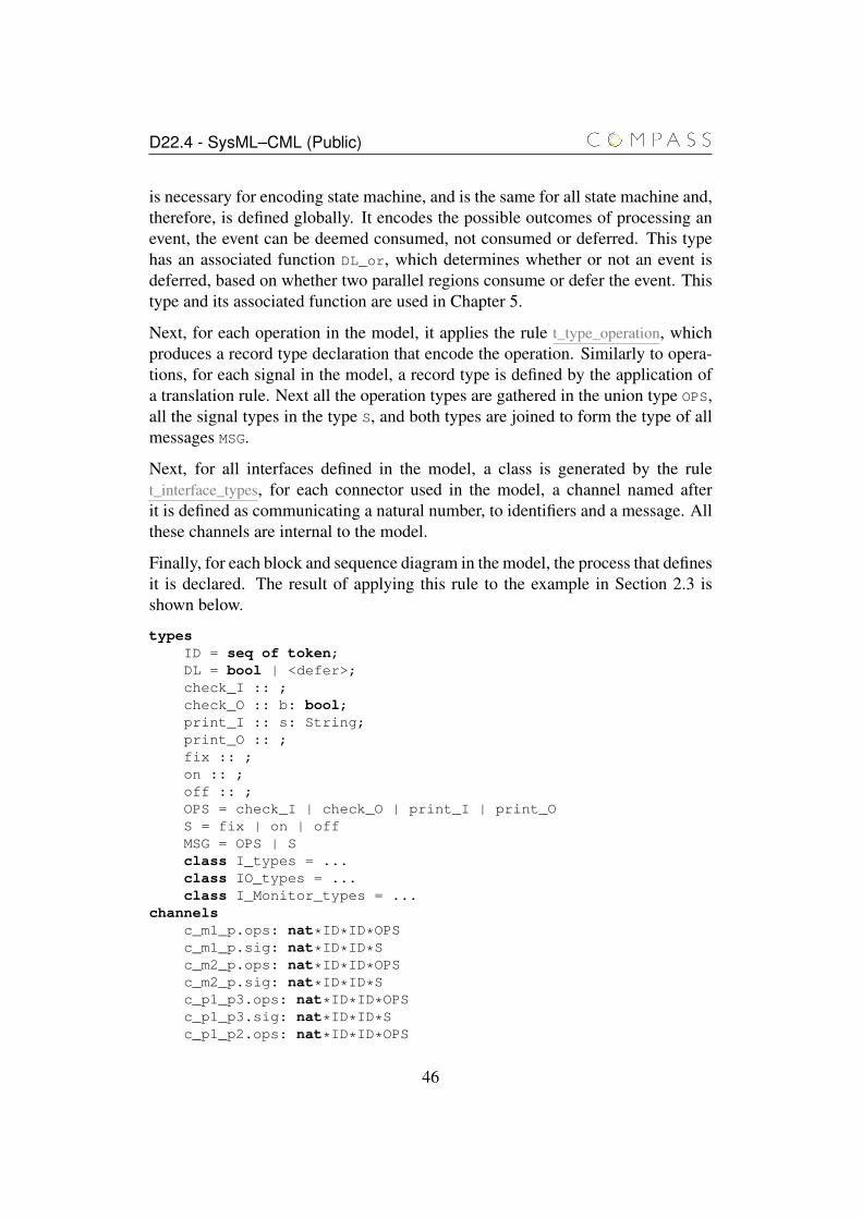
D22.4 - SysML–CML (Public)
is necessary for encoding state machine, and is the same for all state machine and,therefore, is defined globally. It encodes the possible outcomes of processing anevent, the event can be deemed consumed, not consumed or deferred. This typehas an associated function DL_or, which determines whether or not an event isdeferred, based on whether two parallel regions consume or defer the event. Thistype and its associated function are used in Chapter 5.
Next, for each operation in the model, it applies the rule t_type_operation, whichproduces a record type declaration that encode the operation. Similarly to opera-tions, for each signal in the model, a record type is defined by the application ofa translation rule. Next all the operation types are gathered in the union type OPS,all the signal types in the type S, and both types are joined to form the type of allmessages MSG.
Next, for all interfaces defined in the model, a class is generated by the rulet_interface_types, for each connector used in the model, a channel named afterit is defined as communicating a natural number, to identifiers and a message. Allthese channels are internal to the model.
Finally, for each block and sequence diagram in the model, the process that definesit is declared. The result of applying this rule to the example in Section 2.3 isshown below.
typesID = seq of token;DL = bool | <defer>;check_I :: ;check_O :: b: bool;print_I :: s: String;print_O :: ;fix :: ;on :: ;off :: ;OPS = check_I | check_O | print_I | print_OS = fix | on | offMSG = OPS | Sclass I_types = ...class IO_types = ...class I_Monitor_types = ...
channelsc_m1_p.ops: nat*ID*ID*OPSc_m1_p.sig: nat*ID*ID*Sc_m2_p.ops: nat*ID*ID*OPSc_m2_p.sig: nat*ID*ID*Sc_p1_p3.ops: nat*ID*ID*OPSc_p1_p3.sig: nat*ID*ID*Sc_p1_p2.ops: nat*ID*ID*OPS
46
D22.4 - SysML–CML (Public)
c_p1_p2.sig: nat*ID*ID*SfunctionsDL_or(a: DL, b: DL) c: DLpost (is_bool(a) and is_bool(b) => c = a or b)
and (not is_bool(a) or not is_bool(b) => (((a = true) or (b = true) => (c = true))and ((not (a = true) and not (b = true)) => c = <defer>)
))
...process Machine = ......process Screen = ......process Monitor = ......process System = ......process sd_pos = ......process sd_neg = ...
The semantics of the whole model is given by the process System, which cor-responds to the root block System. Larger definitions and auxiliary declarationscovered in the following chapters are elided.
The rule t_types shown in the previous section takes simple SysML types (e.g, Int)and outputs equivalent CML types. A block name used as a type corresponds tothe set of instances of that block; it is translated to the type ID, which identifiesinstances of blocks. A type with multiplicity (i.e., X[n]) is translated into a se-quence of the CML types associated with the component type (i.e., X). Finally,any other types are associated with the generic CML type token, which supportsonly equality comparison. The remaining rules used in t_model are defined andexplained in the next chapters.
3.4 Final remarks
In this chapter, we have presented our guidelines of usage of SysML that allowsus to formalise the semantics of SysML models, the conventions adopted in thepresentation of the translation rules, and the rule that is the root of out translation:t_model. Additionally, we have presented the rule for the translation of types,which is used through out the next chapters.
47
D22.4 - SysML–CML (Public)
The semantics specified by these translation rules and the ones that follow pro-vides a view of the system where the number of instances of blocks as well asthe communication structure is fixed. In order to support dynamic creation anddestruction of blocks, and reconfiguration of the dynamic structure, we requireSysML patterns that support the specification of these behaviours. To the best ofour knowledge, such patterns do not yet exist.
48
Chapter 4
Structural diagrams
In this chapter, we present the semantics of blocks specified by means of blockdefinition diagrams and internal block diagrams. Our translation is based on theunderlying SysML model as described by the meta-model of SysML [Obj10a]. InSysML the diagrams are seen as potentially disjoint views of a cohesive model.For instance, the same block may appear in two different diagrams, showing oneoperation in one diagram, and a different operation on another diagram. The di-agrams are two different view of the same block, each emphasising a differentoperation. The block in the underlying model contains both operations.
The construction of this underlying model is akin to the task of parsing and typechecking a CML file. A abstract syntax tree is built from the CML file, elementsof the concrete syntax are converted into elements of the abstract syntax, andcertain information is inferred from the tree (e.g., that used operations are definedsomewhere in the model). In the case of SysML, this task is carried out by thechosen modelling tool, but the resulting abstract syntax tree (underlying model)must respect the abstract syntax (meta-model) specified in the standard of thelanguage.
We exemplify our semantics for blocks through the example in Section 2.3 and amodel of the classic producer consumer problem. The block definition diagram forthis new model is shown in Figure 4.1. It clearly respects the guidelines describedin Section 3.1, and the semantics of the whole diagram is the semantics of the rootof the composition tree, that is, the block ProducerConsumer. In particular, inthis chapter we use the diagrams shown in figures 4.1, 4.2 and 4.3.
Section 4.1 presents an overview of the semantics of blocks, Sections 4.2 and 4.3present the translation rules for operations, signals and interfaces. Section 4.4presents the rules that define the semantics of ports. Finally, Sections 4.5 and 4.6
49
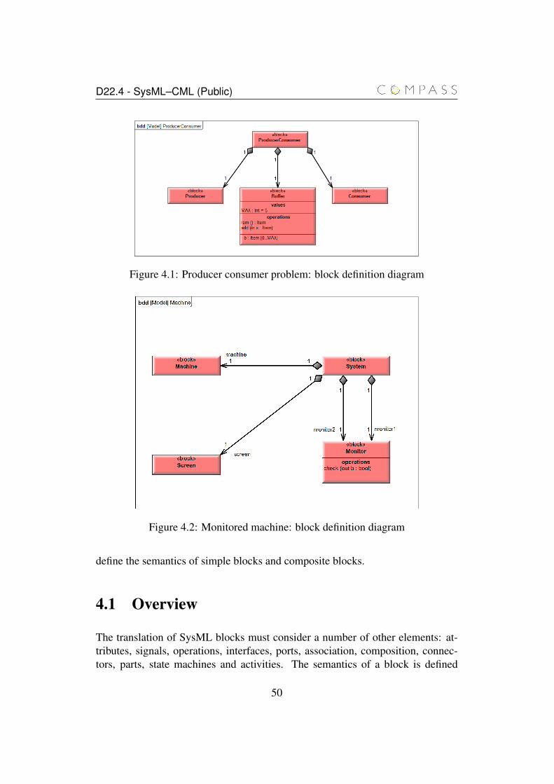
D22.4 - SysML–CML (Public)
Figure 4.1: Producer consumer problem: block definition diagram
Figure 4.2: Monitored machine: block definition diagram
define the semantics of simple blocks and composite blocks.
4.1 Overview
The translation of SysML blocks must consider a number of other elements: at-tributes, signals, operations, interfaces, ports, association, composition, connec-tors, parts, state machines and activities. The semantics of a block is defined
50
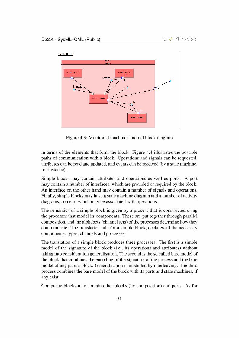
D22.4 - SysML–CML (Public)
Figure 4.3: Monitored machine: internal block diagram
in terms of the elements that form the block. Figure 4.4 illustrates the possiblepaths of communication with a block. Operations and signals can be requested,attributes can be read and updated, and events can be received (by a state machine,for instance).
Simple blocks may contain attributes and operations as well as ports. A portmay contain a number of interfaces, which are provided or required by the block.An interface on the other hand may contain a number of signals and operations.Finally, simple blocks may have a state machine diagram and a number of activitydiagrams, some of which may be associated with operations.
The semantics of a simple block is given by a process that is constructed usingthe processes that model its components. These are put together through parallelcomposition, and the alphabets (channel sets) of the processes determine how theycommunicate. The translation rule for a simple block, declares all the necessarycomponents: types, channels and processes.
The translation of a simple block produces three processes. The first is a simplemodel of the signature of the block (i.e., its operations and attributes) withouttaking into consideration generalisation. The second is the so called bare model ofthe block that combines the encoding of the signature of the process and the baremodel of any parent block. Generalisation is modelled by interleaving. The thirdprocess combines the bare model of the block with its ports and state machines, ifany exist.
Composite blocks may contain other blocks (by composition) and ports. As for
51
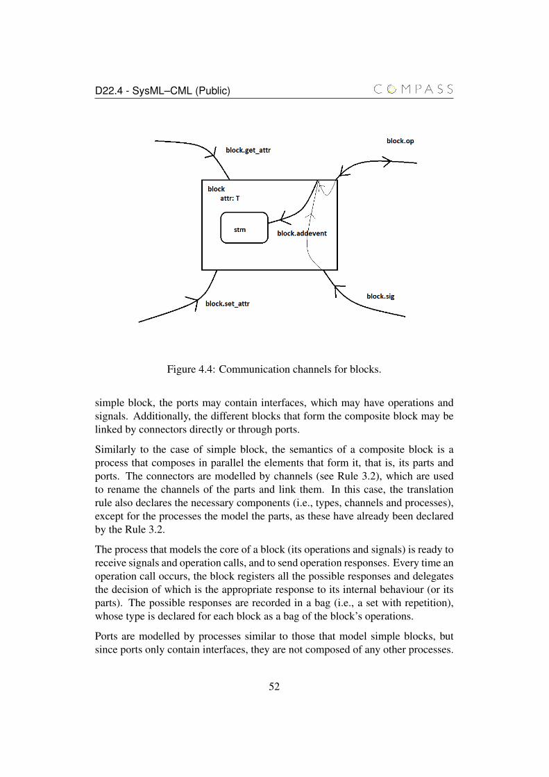
D22.4 - SysML–CML (Public)
Figure 4.4: Communication channels for blocks.
simple block, the ports may contain interfaces, which may have operations andsignals. Additionally, the different blocks that form the composite block may belinked by connectors directly or through ports.
Similarly to the case of simple block, the semantics of a composite block is aprocess that composes in parallel the elements that form it, that is, its parts andports. The connectors are modelled by channels (see Rule 3.2), which are usedto rename the channels of the parts and link them. In this case, the translationrule also declares the necessary components (i.e., types, channels and processes),except for the processes the model the parts, as these have already been declaredby the Rule 3.2.
The process that models the core of a block (its operations and signals) is ready toreceive signals and operation calls, and to send operation responses. Every time anoperation call occurs, the block registers all the possible responses and delegatesthe decision of which is the appropriate response to its internal behaviour (or itsparts). The possible responses are recorded in a bag (i.e., a set with repetition),whose type is declared for each block as a bag of the block’s operations.
Ports are modelled by processes similar to those that model simple blocks, butsince ports only contain interfaces, they are not composed of any other processes.
52
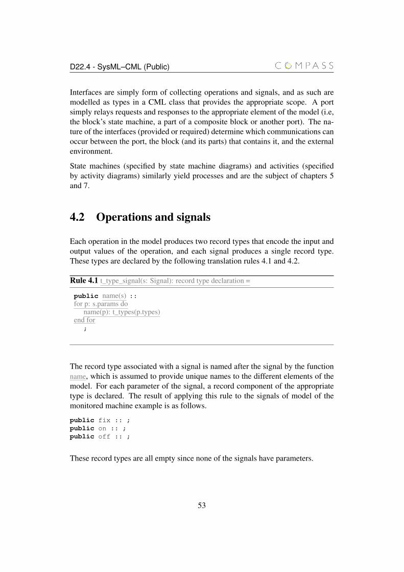
D22.4 - SysML–CML (Public)
Interfaces are simply form of collecting operations and signals, and as such aremodelled as types in a CML class that provides the appropriate scope. A portsimply relays requests and responses to the appropriate element of the model (i.e,the block’s state machine, a part of a composite block or another port). The na-ture of the interfaces (provided or required) determine which communications canoccur between the port, the block (and its parts) that contains it, and the externalenvironment.
State machines (specified by state machine diagrams) and activities (specifiedby activity diagrams) similarly yield processes and are the subject of chapters 5and 7.
4.2 Operations and signals
Each operation in the model produces two record types that encode the input andoutput values of the operation, and each signal produces a single record type.These types are declared by the following translation rules 4.1 and 4.2.
Rule 4.1 t_type_signal(s: Signal): record type declaration =
public name(s) ::for p: s.params do
name(p): t_types(p.types)end for
;
The record type associated with a signal is named after the signal by the functionname, which is assumed to provide unique names to the different elements of themodel. For each parameter of the signal, a record component of the appropriatetype is declared. The result of applying this rule to the signals of model of themonitored machine example is as follows.
public fix :: ;public on :: ;public off :: ;
These record types are all empty since none of the signals have parameters.
53
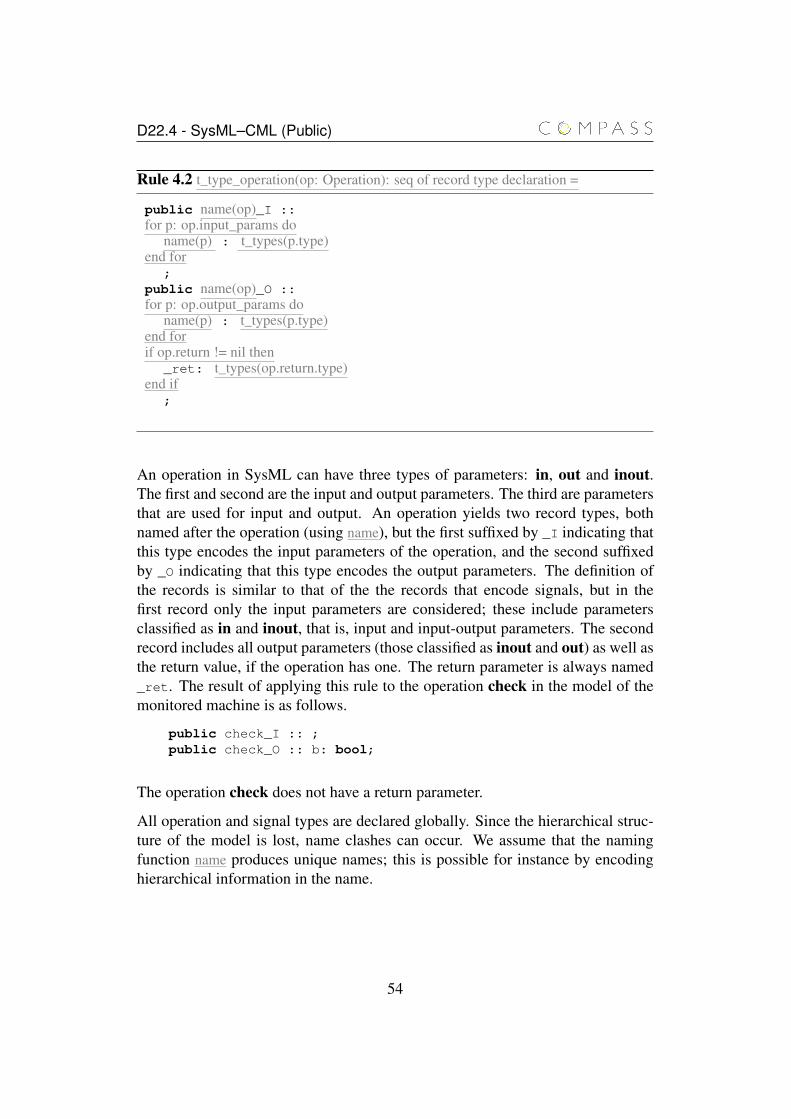
D22.4 - SysML–CML (Public)
Rule 4.2 t_type_operation(op: Operation): seq of record type declaration =
public name(op)_I ::for p: op.input_params do
name(p) : t_types(p.type)end for
;public name(op)_O ::for p: op.output_params do
name(p) : t_types(p.type)end forif op.return != nil then
_ret: t_types(op.return.type)end if
;
An operation in SysML can have three types of parameters: in, out and inout.The first and second are the input and output parameters. The third are parametersthat are used for input and output. An operation yields two record types, bothnamed after the operation (using name), but the first suffixed by _I indicating thatthis type encodes the input parameters of the operation, and the second suffixedby _O indicating that this type encodes the output parameters. The definition ofthe records is similar to that of the the records that encode signals, but in thefirst record only the input parameters are considered; these include parametersclassified as in and inout, that is, input and input-output parameters. The secondrecord includes all output parameters (those classified as inout and out) as well asthe return value, if the operation has one. The return parameter is always named_ret. The result of applying this rule to the operation check in the model of themonitored machine is as follows.
public check_I :: ;public check_O :: b: bool;
The operation check does not have a return parameter.
All operation and signal types are declared globally. Since the hierarchical struc-ture of the model is lost, name clashes can occur. We assume that the namingfunction name produces unique names; this is possible for instance by encodinghierarchical information in the name.
54
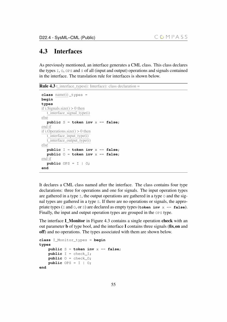
D22.4 - SysML–CML (Public)
4.3 Interfaces
As previously mentioned, an interface generates a CML class. This class declaresthe types I, O, OPS and S of all (input and output) operations and signals containedin the interface. The translation rule for interfaces is shown below.
Rule 4.3 t_interface_types(i: Interface): class declaration =
class name(i) _types =begintypesif i.Signals.size() > 0 then
t_interface_signal_type(i)else
public S = token inv x == false;end ifif i.Operations.size() > 0 then
t_interface_input_type(i)t_interface_output_type(i)
elsepublic I = token inv x == false;public O = token inv x == false;
end ifpublic OPS = I | O;
end
It declares a CML class named after the interface. The class contains four typedeclarations: three for operations and one for signals. The input operation typesare gathered in a type I, the output operations are gathered in a type O and the sig-nal types are gathered in a type S. If there are no operations or signals, the appro-priate types (I and O, or S) are declared as empty types (token inv x == false).Finally, the input and output operation types are grouped in the OPS type.
The interface I_Monitor in Figure 4.3 contains a single operation check with anout parameter b of type bool, and the interface I contains three signals (fix,on andoff) and no operations. The types associated with them are shown below.
class I_Monitor_types = begintypes
public S = token inv x == false;public I = check_I;public O = check_O;public OPS = I | O;
end
55
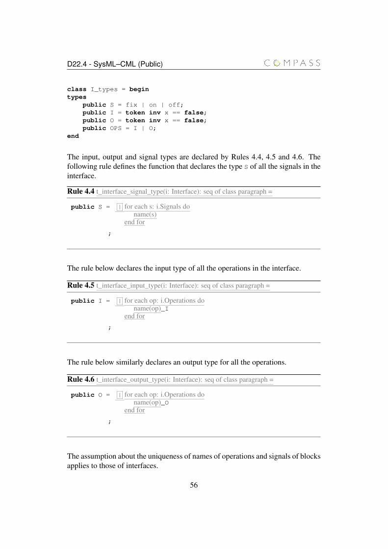
D22.4 - SysML–CML (Public)
class I_types = begintypes
public S = fix | on | off;public I = token inv x == false;public O = token inv x == false;public OPS = I | O;
end
The input, output and signal types are declared by Rules 4.4, 4.5 and 4.6. Thefollowing rule defines the function that declares the type S of all the signals in theinterface.
Rule 4.4 t_interface_signal_type(i: Interface): seq of class paragraph =
public S = | for each s: i.Signals doname(s)
end for
;
The rule below declares the input type of all the operations in the interface.
Rule 4.5 t_interface_input_type(i: Interface): seq of class paragraph =
public I = | for each op: i.Operations doname(op)_I
end for
;
The rule below similarly declares an output type for all the operations.
Rule 4.6 t_interface_output_type(i: Interface): seq of class paragraph =
public O = | for each op: i.Operations doname(op)_O
end for
;
The assumption about the uniqueness of names of operations and signals of blocksapplies to those of interfaces.
56
D22.4 - SysML–CML (Public)
4.4 Standard ports
As already said, a standard port is a mechanism for communication betweenblocks without a specific reference to a block instance. We model a standardport similarly to a simple block, except that it does not treat the received request:it simply relays it to the appropriate block.
For the purpose of our semantics, we distinguish two sides of a port: external andinternal. If the port belongs to a simple block, than the internal side is connectedimplicitly to the block itself. If the port belongs to a composite block, it must beexplicitly connected to a port of one of the parts of the block.
The set of provided and required interfaces connected to a port determine thepossible patterns of communication of a port. In the most general case, a port hasa set of provided interfaces (PI) and a set of required interfaces (RI). For instance,for the port p1 in Figure 4.3, we have the following sets:
RI = {I}PI = {IO}
These sets of interfaces are determined with respect to the external side of theport and are implicitly mirrored on the internal side. A provided interface is mir-rored in a required internal interface on the same port, and a required interface ismirrored in a provided internal interface on the same port. For instance, the pro-vided interface I on port p3 is implicitly mirrored as a required interface on portp3.
In our CML model, a port gives rise to four channels of communication (two foroperations and two for signals) associated with its sides: internal and external.Signals are asynchronous communications, whereas operations are consideredsynchronous in our semantics. The patterns of communication on these chan-nels depend on the nature of the requests. Operations in a provided interface canonly be requested on the external operation channel, and operations in a requiredinterface can only be requested on the internal channel.
The types associated with a port are those of its interfaces. They are groupedaccording to the type of interface (provided or required), and whether the typerefers to a signal or operation. The following rule declares the types associatedwith a port and is used in the definition of a port as specified by the Rule 4.7.
57
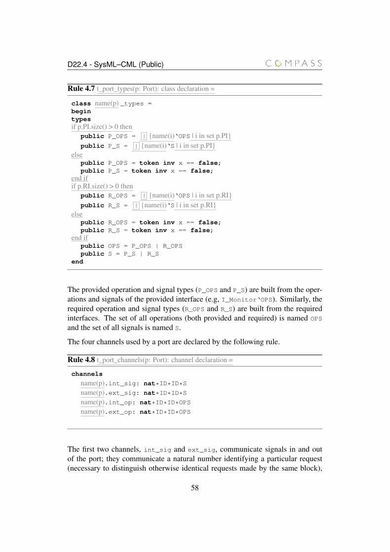
D22.4 - SysML–CML (Public)
Rule 4.7 t_port_types(p: Port): class declaration =
class name(p) _types =begintypesif p.PI.size() > 0 then
public P_OPS = | {name(i)‘OPS | i in set p.PI}public P_S = | {name(i)‘S | i in set p.PI}
elsepublic P_OPS = token inv x == false;public P_S = token inv x == false;
end ifif p.RI.size() > 0 then
public R_OPS = | {name(i)‘OPS | i in set p.RI}public R_S = | {name(i)‘S | i in set p.RI}
elsepublic R_OPS = token inv x == false;public R_S = token inv x == false;
end ifpublic OPS = P_OPS | R_OPSpublic S = P_S | R_S
end
The provided operation and signal types (P_OPS and P_S) are built from the oper-ations and signals of the provided interface (e.g, I_Monitor‘OPS). Similarly, therequired operation and signal types (R_OPS and R_S) are built from the requiredinterfaces. The set of all operations (both provided and required) is named OPS
and the set of all signals is named S.
The four channels used by a port are declared by the following rule.
Rule 4.8 t_port_channels(p: Port): channel declaration =
channels
name(p).int_sig: nat*ID*ID*S
name(p).ext_sig: nat*ID*ID*S
name(p).int_op: nat*ID*ID*OPS
name(p).ext_op: nat*ID*ID*OPS
The first two channels, int_sig and ext_sig, communicate signals in and outof the port; they communicate a natural number identifying a particular request(necessary to distinguish otherwise identical requests made by the same block),
58
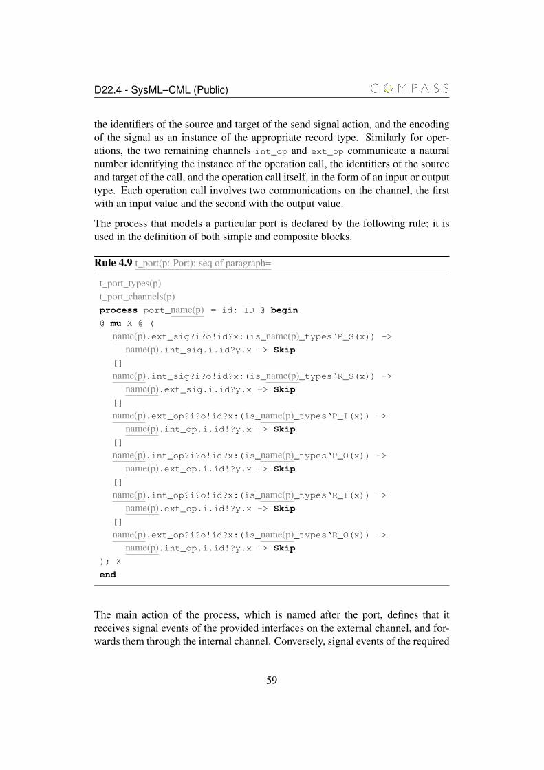
D22.4 - SysML–CML (Public)
the identifiers of the source and target of the send signal action, and the encodingof the signal as an instance of the appropriate record type. Similarly for oper-ations, the two remaining channels int_op and ext_op communicate a naturalnumber identifying the instance of the operation call, the identifiers of the sourceand target of the call, and the operation call itself, in the form of an input or outputtype. Each operation call involves two communications on the channel, the firstwith an input value and the second with the output value.
The process that models a particular port is declared by the following rule; it isused in the definition of both simple and composite blocks.
Rule 4.9 t_port(p: Port): seq of paragraph=
t_port_types(p)t_port_channels(p)process port_name(p) = id: ID @ begin
@ mu X @ (
name(p).ext_sig?i?o!id?x:(is_name(p)_types‘P_S(x)) ->
name(p).int_sig.i.id?y.x -> Skip
[]
name(p).int_sig?i?o!id?x:(is_name(p)_types‘R_S(x)) ->
name(p).ext_sig.i.id?y.x -> Skip
[]
name(p).ext_op?i?o!id?x:(is_name(p)_types‘P_I(x)) ->
name(p).int_op.i.id!?y.x -> Skip
[]
name(p).int_op?i?o!id?x:(is_name(p)_types‘P_O(x)) ->
name(p).ext_op.i.id!?y.x -> Skip
[]
name(p).int_op?i?o!id?x:(is_name(p)_types‘R_I(x)) ->
name(p).ext_op.i.id!?y.x -> Skip
[]
name(p).ext_op?i?o!id?x:(is_name(p)_types‘R_O(x)) ->
name(p).int_op.i.id!?y.x -> Skip
); X
end
The main action of the process, which is named after the port, defines that itreceives signal events of the provided interfaces on the external channel, and for-wards them through the internal channel. Conversely, signal events of the required
59
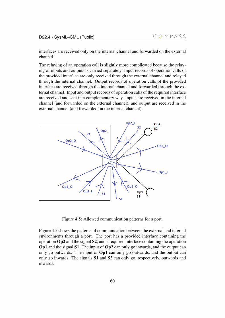
D22.4 - SysML–CML (Public)
interfaces are received only on the internal channel and forwarded on the externalchannel.
The relaying of an operation call is slightly more complicated because the relay-ing of inputs and outputs is carried separately. Input records of operation calls ofthe provided interface are only received through the external channel and relayedthrough the internal channel. Output records of operation calls of the providedinterface are received through the internal channel and forwarded through the ex-ternal channel. Input and output records of operation calls of the required interfaceare received and sent in a complementary way. Inputs are received in the internalchannel (and forwarded on the external channel), and output are received in theexternal channel (and forwarded on the internal channel).
Figure 4.5: Allowed communication patterns for a port.
Figure 4.5 shows the patterns of communication between the external and internalenvironments through a port. The port has a provided interface containing theoperation Op2 and the signal S2, and a required interface containing the operationOp1 and the signal S1. The input of Op2 can only go inwards, and the output canonly go outwards. The input of Op1 can only go outwards, and the output canonly go inwards. The signals S1 and S2 can only go, respectively, outwards andinwards.
60
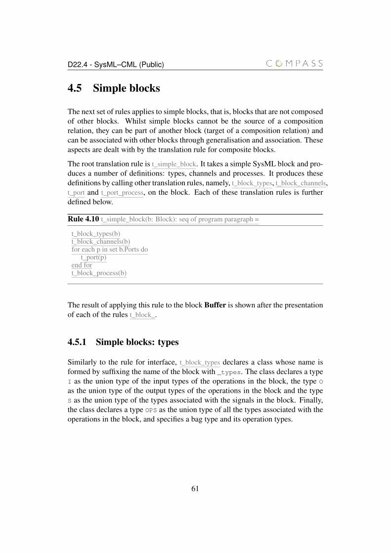
D22.4 - SysML–CML (Public)
4.5 Simple blocks
The next set of rules applies to simple blocks, that is, blocks that are not composedof other blocks. Whilst simple blocks cannot be the source of a compositionrelation, they can be part of another block (target of a composition relation) andcan be associated with other blocks through generalisation and association. Theseaspects are dealt with by the translation rule for composite blocks.
The root translation rule is t_simple_block. It takes a simple SysML block and pro-duces a number of definitions: types, channels and processes. It produces thesedefinitions by calling other translation rules, namely, t_block_types, t_block_channels,t_port and t_port_process, on the block. Each of these translation rules is furtherdefined below.
Rule 4.10 t_simple_block(b: Block): seq of program paragraph =
t_block_types(b)t_block_channels(b)for each p in set b.Ports do
t_port(p)end fort_block_process(b)
The result of applying this rule to the block Buffer is shown after the presentationof each of the rules t_block_.
4.5.1 Simple blocks: types
Similarly to the rule for interface, t_block_types declares a class whose name isformed by suffixing the name of the block with _types. The class declares a typeI as the union type of the input types of the operations in the block, the type O
as the union type of the output types of the operations in the block and the typeS as the union type of the types associated with the signals in the block. Finally,the class declares a type OPS as the union type of all the types associated with theoperations in the block, and specifies a bag type and its operation types.
61
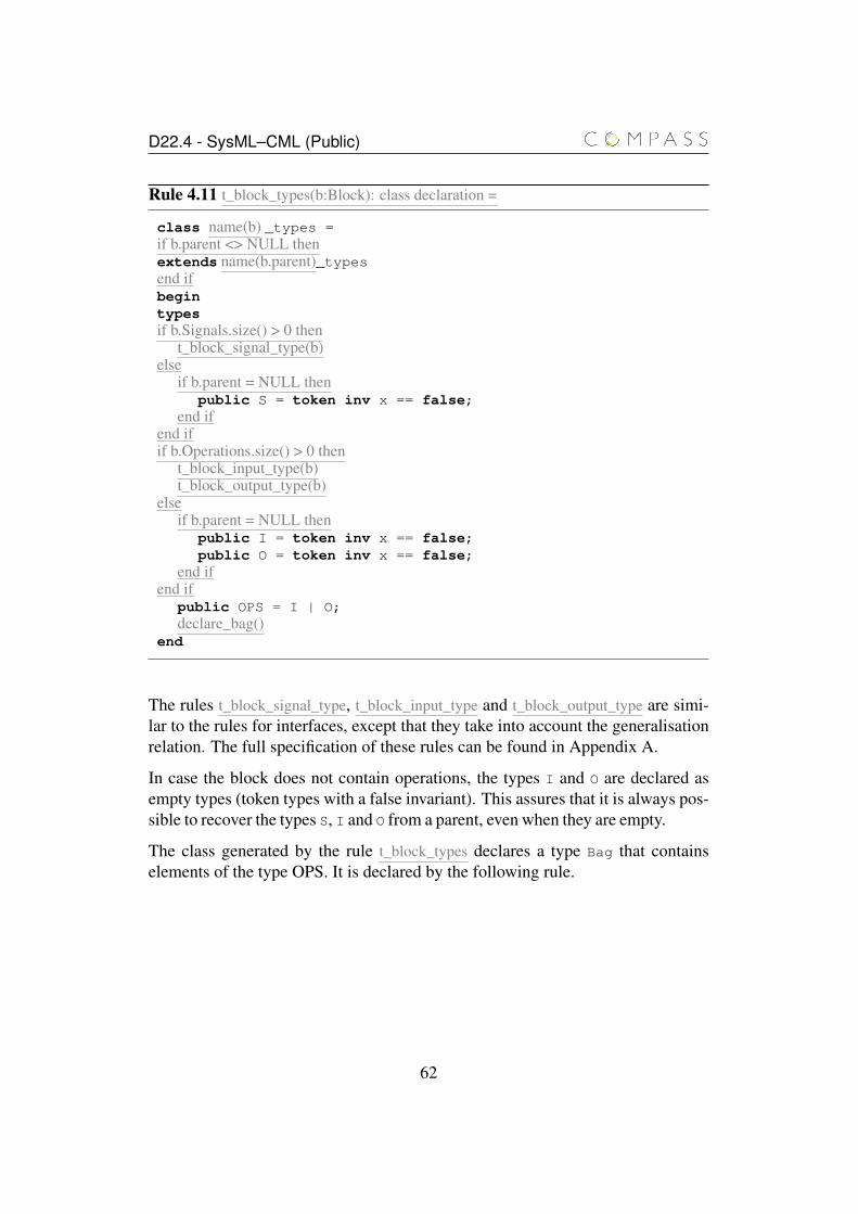
D22.4 - SysML–CML (Public)
Rule 4.11 t_block_types(b:Block): class declaration =
class name(b) _types =if b.parent <> NULL thenextends name(b.parent)_typesend ifbegintypesif b.Signals.size() > 0 then
t_block_signal_type(b)else
if b.parent = NULL thenpublic S = token inv x == false;
end ifend ifif b.Operations.size() > 0 then
t_block_input_type(b)t_block_output_type(b)
elseif b.parent = NULL then
public I = token inv x == false;public O = token inv x == false;
end ifend if
public OPS = I | O;declare_bag()
end
The rules t_block_signal_type, t_block_input_type and t_block_output_type are simi-lar to the rules for interfaces, except that they take into account the generalisationrelation. The full specification of these rules can be found in Appendix A.
In case the block does not contain operations, the types I and O are declared asempty types (token types with a false invariant). This assures that it is always pos-sible to recover the types S, I and O from a parent, even when they are empty.
The class generated by the rule t_block_types declares a type Bag that containselements of the type OPS. It is declared by the following rule.
62
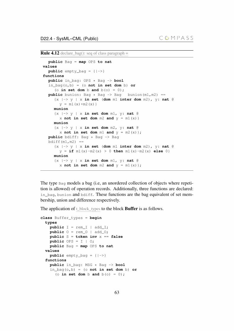
D22.4 - SysML–CML (Public)
Rule 4.12 declare_bag(): seq of class paragraph =
public Bag = map OPS to natvalues
public empty_bag = {|->}functions
public in_bag: OPS * Bag -> boolin_bag(o,b) = (o not in set dom b) or
(o in set dom b and b(o) = 0);public bunion: Bag * Bag -> Bag bunion(m1,m2) ==
{x |-> y | x in set (dom m1 inter dom m2), y: nat @y = m1(x)+m2(x)}
munion{x |-> y | x in set dom m1, y: nat @
x not in set dom m2 and y = m1(x)}munion{x |-> y | x in set dom m2, y: nat @
x not in set dom m1 and y = m2(x)};public bdiff: Bag * Bag -> Bagbdiff(m1,m2) ==
{x |-> y | x in set (dom m1 inter dom m2), y: nat @y = if m1(x)-m2(x) > 0 then m1(x)-m2(x) else 0}
munion{x |-> y | x in set dom m1, y: nat @
x not in set dom m2 and y = m1(x)};
The type Bag models a bag (i.e, an unordered collection of objects where repeti-tion is allowed) of operation records. Additionally, three functions are declared:in_bag, bunion and bdiff. These functions are the bag equivalent of set mem-bership, union and difference respectively.
The application of t_block_types to the block Buffer is as follows.
class Buffer_types = begintypes
public I = rem_I | add_I;public O = rem_O | add_O;public S = token inv x == falsepublic OPS = I | O;public Bag = map OPS to nat
valuespublic empty_bag = {|->}
functionspublic in_bag: MSG * Bag -> boolin_bag(o,b) = (o not in set dom b) or
(o in set dom b and b(o) = 0);
63
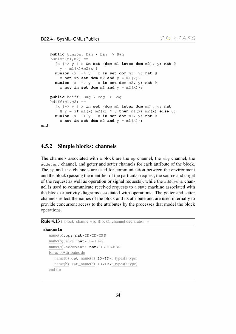
D22.4 - SysML–CML (Public)
public bunion: Bag * Bag -> Bagbunion(m1,m2) ==
{x |-> y | x in set (dom m1 inter dom m2), y: nat @y = m1(x)+m2(x)}
munion {x |-> y | x in set dom m1, y: nat @x not in set dom m2 and y = m1(x)}
munion {x |-> y | x in set dom m2, y: nat @x not in set dom m1 and y = m2(x)};
public bdiff: Bag * Bag -> Bagbdiff(m1,m2) =={x |-> y | x in set (dom m1 inter dom m2), y: nat
@ y = if m1(x)-m2(x) > 0 then m1(x)-m2(x) else 0}munion {x |-> y | x in set dom m1, y: nat @
x not in set dom m2 and y = m1(x)};end
4.5.2 Simple blocks: channels
The channels associated with a block are the op channel, the sig channel, theaddevent channel, and getter and setter channels for each attribute of the block.The op and sig channels are used for communication between the environmentand the block (passing the identifier of the particular request, the source and targetof the request as well as operation or signal requests), while the addevent chan-nel is used to communicate received requests to a state machine associated withthe block or activity diagrams associated with operations. The getter and setterchannels reflect the names of the block and its attribute and are used internally toprovide concurrent access to the attributes by the processes that model the blockoperations.
Rule 4.13 t_block_channels(b: Block): channel declaration =
channels
name(b).op: nat*ID*ID*OPS
name(b).sig: nat*ID*ID*S
name(b).addevent: nat*ID*ID*MSG
for a: b.Attributes doname(b).get_name(a):ID*ID*t_types(a.type)name(b).set_name(a):ID*ID*t_types(a.type)
end for
64
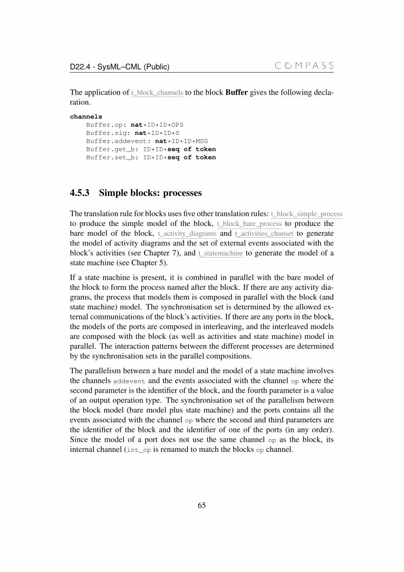
D22.4 - SysML–CML (Public)
The application of t_block_channels to the block Buffer gives the following decla-ration.
channelsBuffer.op: nat*ID*ID*OPSBuffer.sig: nat*ID*ID*SBuffer.addevent: nat*ID*ID*MSGBuffer.get_b: ID*ID*seq of tokenBuffer.set_b: ID*ID*seq of token
4.5.3 Simple blocks: processes
The translation rule for blocks uses five other translation rules: t_block_simple_processto produce the simple model of the block, t_block_bare_process to produce thebare model of the block, t_activity_diagrams and t_activities_chanset to generatethe model of activity diagrams and the set of external events associated with theblock’s activities (see Chapter 7), and t_statemachine to generate the model of astate machine (see Chapter 5).
If a state machine is present, it is combined in parallel with the bare model ofthe block to form the process named after the block. If there are any activity dia-grams, the process that models them is composed in parallel with the block (andstate machine) model. The synchronisation set is determined by the allowed ex-ternal communications of the block’s activities. If there are any ports in the block,the models of the ports are composed in interleaving, and the interleaved modelsare composed with the block (as well as activities and state machine) model inparallel. The interaction patterns between the different processes are determinedby the synchronisation sets in the parallel compositions.
The parallelism between a bare model and the model of a state machine involvesthe channels addevent and the events associated with the channel op where thesecond parameter is the identifier of the block, and the fourth parameter is a valueof an output operation type. The synchronisation set of the parallelism betweenthe block model (bare model plus state machine) and the ports contains all theevents associated with the channel op where the second and third parameters arethe identifier of the block and the identifier of one of the ports (in any order).Since the model of a port does not use the same channel op as the block, itsinternal channel (int_op is renamed to match the blocks op channel.
65
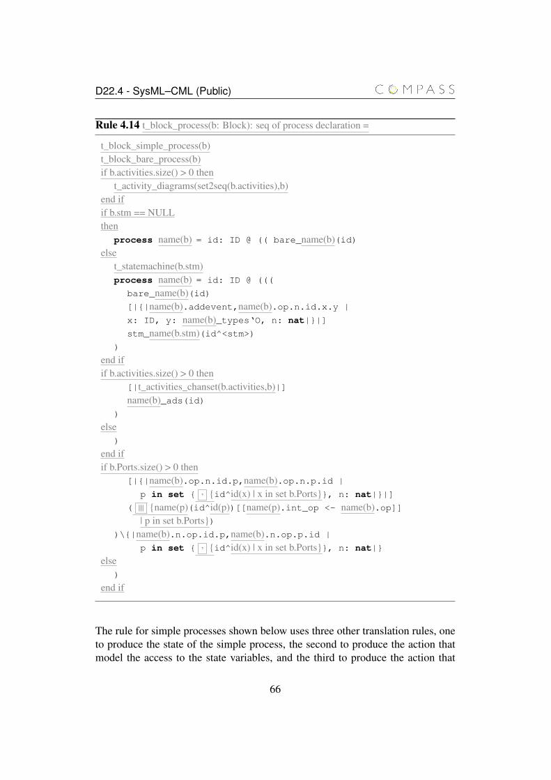
D22.4 - SysML–CML (Public)
Rule 4.14 t_block_process(b: Block): seq of process declaration =
t_block_simple_process(b)t_block_bare_process(b)if b.activities.size() > 0 then
t_activity_diagrams(set2seq(b.activities),b)end ifif b.stm == NULLthen
process name(b) = id: ID @ (( bare_name(b)(id)else
t_statemachine(b.stm)process name(b) = id: ID @ (((
bare_name(b)(id)[|{|name(b).addevent,name(b).op.n.id.x.y |
x: ID, y: name(b)_types‘O, n: nat|}|]
stm_name(b.stm)(id^<stm>))
end ifif b.activities.size() > 0 then
[|t_activities_chanset(b.activities,b)|]name(b)_ads(id)
)
else)
end ifif b.Ports.size() > 0 then
[|{|name(b).op.n.id.p,name(b).op.n.p.id |
p in set { , {id^id(x) | x in set b.Ports}}, n: nat|}|]
( ||| {name(p)(id^id(p))[[name(p).int_op <- name(b).op]]| p in set b.Ports})
)\{|name(b).n.op.id.p,name(b).n.op.p.id |
p in set { , {id^id(x) | x in set b.Ports}}, n: nat|}
else)
end if
The rule for simple processes shown below uses three other translation rules, oneto produce the state of the simple process, the second to produce the action thatmodel the access to the state variables, and the third to produce the action that
66
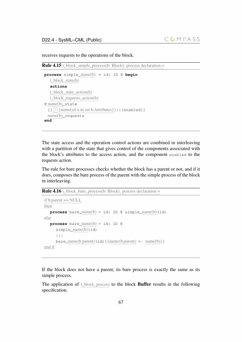
D22.4 - SysML–CML (Public)
receives requests to the operations of the block.
Rule 4.15 t_block_simple_process(b: Block): process declaration =
process simple_name(b) = id: ID @ begin
t_block_state(b)actions
t_block_state_action(b)t_block_requests_action(b)
@ name(b)_state[{ , {name(a)| a in set b.Attributes}}||{enabled}]name(b)_requests
end
The state access and the operation control actions are combined in interleavingwith a partition of the state that gives control of the components associated withthe block’s attributes to the access action, and the component enabled to therequests action.
The rule for bare processes checks whether the block has a parent or not, and if itdoes, composes the bare process of the parent with the simple process of the blockin interleaving.
Rule 4.16 t_block_bare_process(b: Block): process declaration =
if b.parent == NULLthen
process bare_name(b) = id: ID @ simple_name(b)(id)else
process bare_name(b) = id: ID @
simple_name(b)(id)|||
bare_name(b.parent)(id)[[name(b.parent) <- name(b)]]end if
If the block does not have a parent, its bare process is exactly the same as itssimple process.
The application of t_block_process to the block Buffer results in the followingspecification.
67
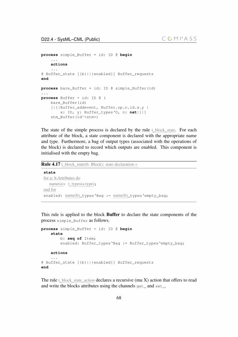
D22.4 - SysML–CML (Public)
process simple_Buffer = id: ID @ begin...actions...
@ Buffer_state [{b}||{enabled}] Buffer_requestsend
process bare_Buffer = id: ID @ simple_Buffer(id)...process Buffer = id: ID @ (
bare_Buffer(id)[|{|Buffer_addevent, Buffer.op.n.id.x.y |
x: ID, y: Buffer_types‘O, n: nat|}|]stm_Buffer(id^<stm>)
The state of the simple process is declared by the rule t_block_state. For eachattribute of the block, a state component is declared with the appropriate nameand type. Furthermore, a bag of output types (associated with the operations ofthe block) is declared to record which outputs are enabled. This component isinitialised with the empty bag.
Rule 4.17 t_block_state(b: Block): state declaration =
state
for a: b.Attributes doname(a): t_types(a.type);
end forenabled: name(b)_types‘Bag := name(b)_types‘empty_bag;
This rule is applied to the block Buffer to declare the state components of theprocess simple_Buffer as follows.
process simple_Buffer = id: ID @ beginstate
b: seq of Item;enabled: Buffer_types‘Bag := Buffer_types‘empty_bag;
actions...
@ Buffer_state [{b}||{enabled}] Buffer_requestsend
The rule t_block_state_action declares a recursive (mu X) action that offers to readand write the blocks attributes using the channels get_ and set_.
68
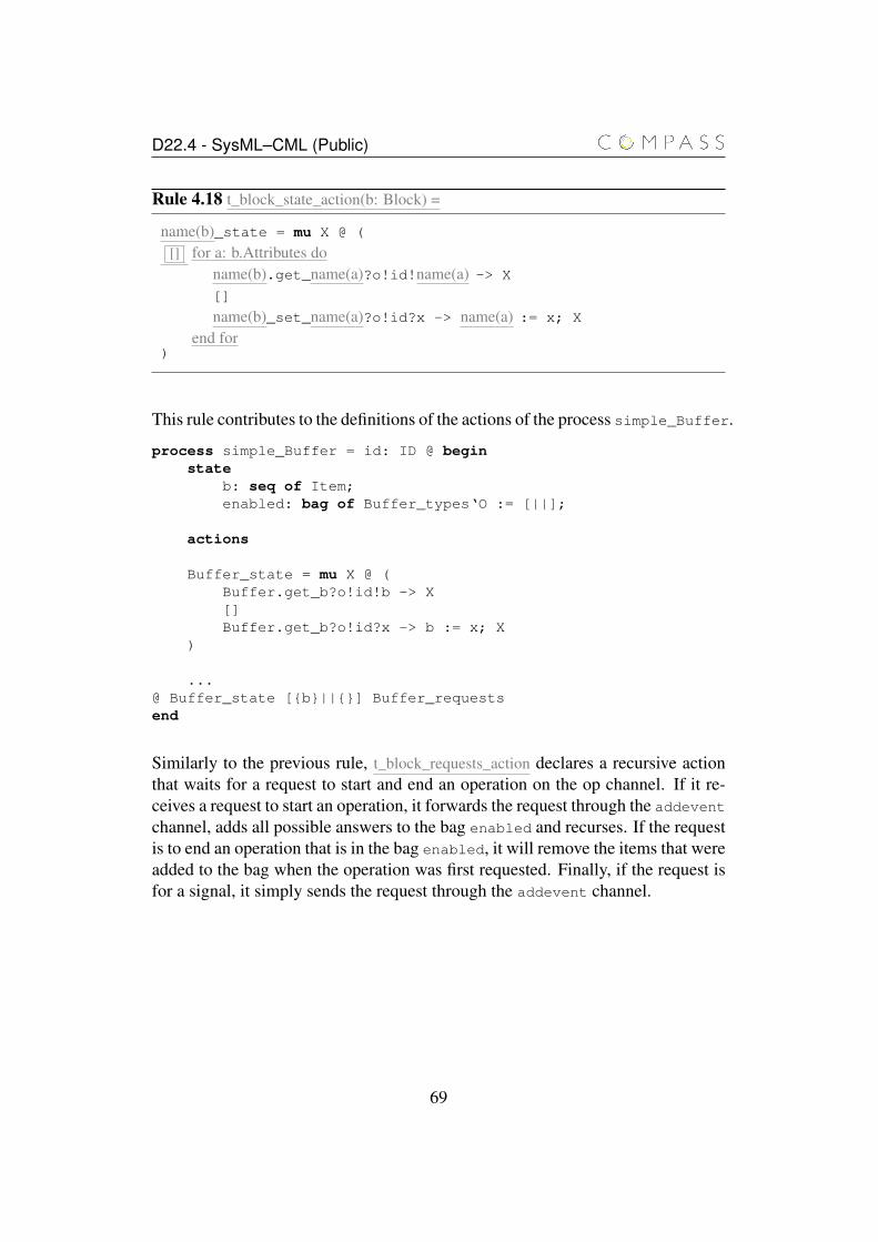
D22.4 - SysML–CML (Public)
Rule 4.18 t_block_state_action(b: Block) =
name(b)_state = mu X @ (
[] for a: b.Attributes doname(b).get_name(a)?o!id!name(a) -> X
[]
name(b)_set_name(a)?o!id?x -> name(a) := x; X
end for)
This rule contributes to the definitions of the actions of the process simple_Buffer.
process simple_Buffer = id: ID @ beginstate
b: seq of Item;enabled: bag of Buffer_types‘O := [||];
actions
Buffer_state = mu X @ (Buffer.get_b?o!id!b -> X[]Buffer.get_b?o!id?x -> b := x; X
)
...@ Buffer_state [{b}||{}] Buffer_requestsend
Similarly to the previous rule, t_block_requests_action declares a recursive actionthat waits for a request to start and end an operation on the op channel. If it re-ceives a request to start an operation, it forwards the request through the addeventchannel, adds all possible answers to the bag enabled and recurses. If the requestis to end an operation that is in the bag enabled, it will remove the items that wereadded to the bag when the operation was first requested. Finally, if the request isfor a signal, it simply sends the request through the addevent channel.
69
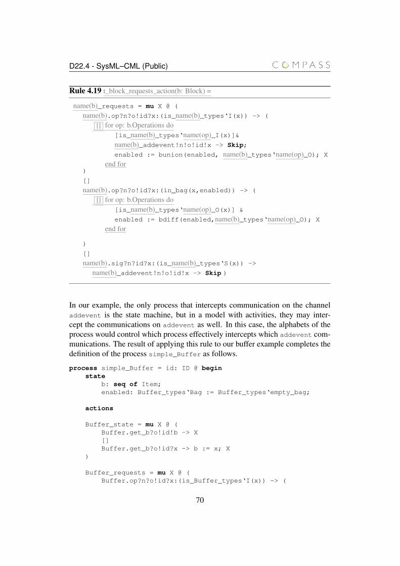
D22.4 - SysML–CML (Public)
Rule 4.19 t_block_requests_action(b: Block) =
name(b)_requests = mu X @ (
name(b).op?n?o!id?x:(is_name(b)_types‘I(x)) -> (
[] for op: b.Operations do[is_name(b)_types‘name(op)_I(x)]&name(b)_addevent!n!o!id!x -> Skip;
enabled := bunion(enabled, name(b)_types‘name(op)_O); X
end for)
[]
name(b).op?n?o!id?x:(in_bag(x,enabled)) -> (
[] for op: b.Operations do[is_name(b)_types‘name(op)_O(x)] &
enabled := bdiff(enabled,name(b)_types‘name(op)_O); X
end for
)
[]
name(b).sig?n?id?x:(is_name(b)_types‘S(x)) ->
name(b)_addevent!n!o!id!x -> Skip )
In our example, the only process that intercepts communication on the channeladdevent is the state machine, but in a model with activities, they may inter-cept the communications on addevent as well. In this case, the alphabets of theprocess would control which process effectively intercepts which addevent com-munications. The result of applying this rule to our buffer example completes thedefinition of the process simple_Buffer as follows.
process simple_Buffer = id: ID @ beginstate
b: seq of Item;enabled: Buffer_types‘Bag := Buffer_types‘empty_bag;
actions
Buffer_state = mu X @ (Buffer.get_b?o!id!b -> X[]Buffer.get_b?o!id?x -> b := x; X
)
Buffer_requests = mu X @ (Buffer.op?n?o!id?x:(is_Buffer_types‘I(x)) -> (
70

D22.4 - SysML–CML (Public)
[is_Buffer_types‘add_I(x)]&Buffer_addevent!n!o!id!x -> Skip;enabled := bunion(enabled,Buffer_types‘add_O); X
[][is_Buffer_types‘rem_I(x)]&
Buffer_addevent!n!o!id!x -> Skip;enabled := bunion(enabled,Buffer_types‘rem_O); X
)[]Buffer.op?n?o!id?x:(in_bag(x,enabled)) -> (
[is_Buffer_types‘add_O(x)]&enabled := bdiff(enabled,Buffer_types‘add_O); X
[][is_Buffer_types‘rem_O(x)]&
enabled := bdiff(enabled,Buffer_types‘rem_O); X)[]Buffer.sig?n?o!id?x:(is_Buffer_types‘S(x)) ->
Buffer_addevent!n!o!id!x -> Skip)
@ Buffer_state [{b}||{enabled}] Buffer_requestsend
This process declares a state formed by the single attribute b of the block Bufferand the set of enabled output enabled. The main action of the process is theinterleaving of two actions: Buffer_state and Buffer_requests. The formercontrols the state and allows communications that read and write to the compo-nents b, and the latter controls the receipt of operation and signal requests. Inthe interleaving, the state is partitioned between the two actions: the componentcorresponding to the block’s attribute is assigned to the first action, and the com-ponent enabled to the second action.
The action that controls the operation and signal requests, receives a value of anoperation input type through the channel Buffer.ops or a value of a signal typethrough the channel Buffer.sig. In the first case, it identifies which operationhas been called, sends the call through the channel Buffer.addevent, and addsall possible answers to the bag enabled, and recurses. In the case of a signalvalue, the action sends the signal through the channel Buffer.addevent, andrecurses.
The rule t_statemachine is defined in the following chapter and its application toour example is illustrated throughout the chapter.
71
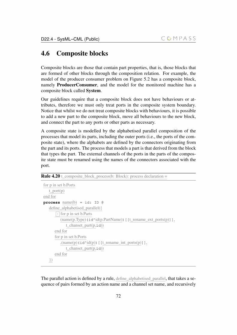
D22.4 - SysML–CML (Public)
4.6 Composite blocks
Composite blocks are those that contain part properties, that is, those blocks thatare formed of other blocks through the composition relation. For example, themodel of the producer consumer problem on Figure 5.2 has a composite block,namely ProducerConsumer, and the model for the monitored machine has acomposite block called System.
Our guidelines require that a composite block does not have behaviours or at-tributes, therefore we must only treat ports in the composite system boundary.Notice that whilst we do not treat composite blocks with behaviours, it is possibleto add a new part to the composite block, move all behaviours to the new block,and connect the part to any ports or other parts as necessary.
A composite state is modelled by the alphabetised parallel composition of theprocesses that model its parts, including the outer ports (i.e., the ports of the com-posite state), where the alphabets are defined by the connectors originating fromthe part and its ports. The process that models a part is that derived from the blockthat types the part. The external channels of the ports in the parts of the compos-ite state must be renamed using the names of the connectors associated with theport.
Rule 4.20 t_composite_block_process(b: Block): process declaration =
for p in set b.Portst_port(p)
end forprocess name(b) = id: ID @
define_alphabetised_parallel({, for p in set b.Parts
(name(p.Type)(id^id(p.PartName))[[t_rename_ext_ports(p)]],t_chanset_part(p,id))
end forfor p in set b.Ports
,(name(p)(id^id(p))[[t_rename_int_ports(p)]],t_chanset_part(p,id))
end for})
The parallel action is defined by a rule, define_alphabetised_parallel, that takes a se-quence of pairs formed by an action name and a channel set name, and recursively
72
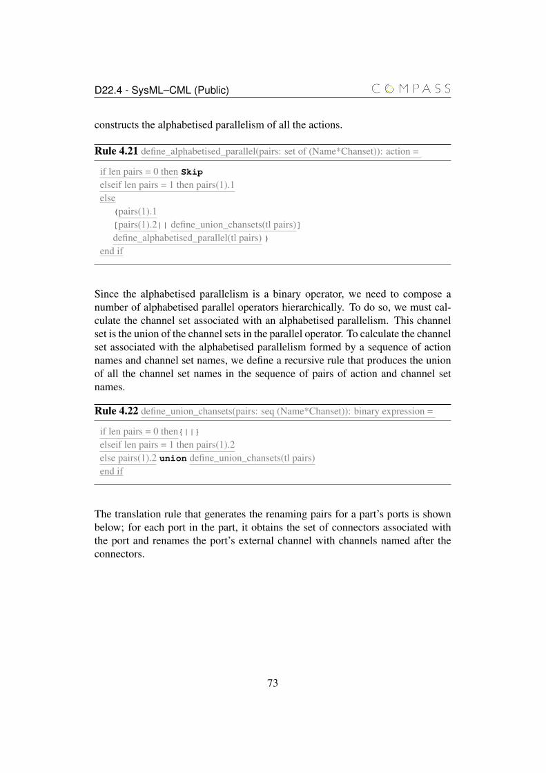
D22.4 - SysML–CML (Public)
constructs the alphabetised parallelism of all the actions.
Rule 4.21 define_alphabetised_parallel(pairs: set of (Name*Chanset)): action =
if len pairs = 0 then Skip
elseif len pairs = 1 then pairs(1).1else
(pairs(1).1[pairs(1).2|| define_union_chansets(tl pairs)]define_alphabetised_parallel(tl pairs) )
end if
Since the alphabetised parallelism is a binary operator, we need to compose anumber of alphabetised parallel operators hierarchically. To do so, we must cal-culate the channel set associated with an alphabetised parallelism. This channelset is the union of the channel sets in the parallel operator. To calculate the channelset associated with the alphabetised parallelism formed by a sequence of actionnames and channel set names, we define a recursive rule that produces the unionof all the channel set names in the sequence of pairs of action and channel setnames.
Rule 4.22 define_union_chansets(pairs: seq (Name*Chanset)): binary expression =
if len pairs = 0 then{||}elseif len pairs = 1 then pairs(1).2else pairs(1).2 union define_union_chansets(tl pairs)end if
The translation rule that generates the renaming pairs for a part’s ports is shownbelow; for each port in the part, it obtains the set of connectors associated withthe port and renames the port’s external channel with channels named after theconnectors.
73
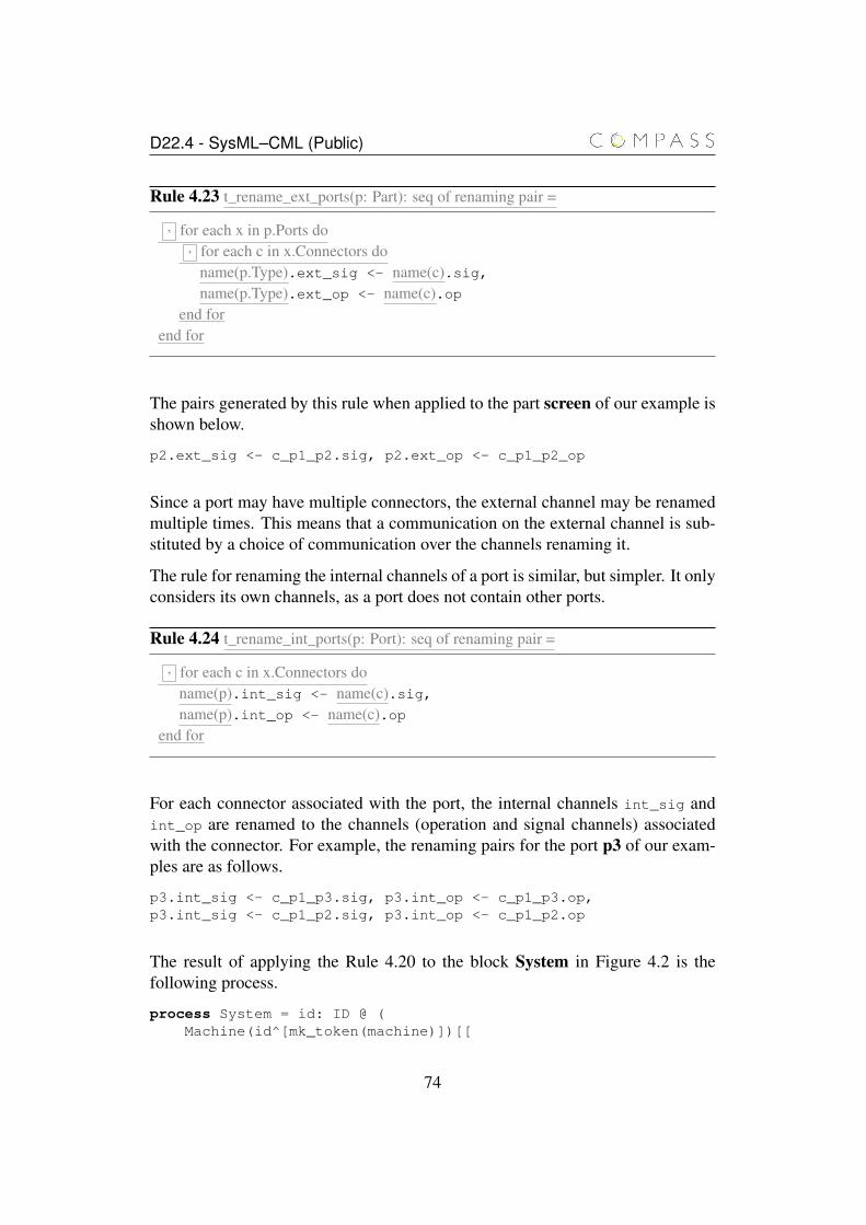
D22.4 - SysML–CML (Public)
Rule 4.23 t_rename_ext_ports(p: Part): seq of renaming pair =
, for each x in p.Ports do, for each c in x.Connectors do
name(p.Type).ext_sig <- name(c).sig,name(p.Type).ext_op <- name(c).op
end forend for
The pairs generated by this rule when applied to the part screen of our example isshown below.
p2.ext_sig <- c_p1_p2.sig, p2.ext_op <- c_p1_p2_op
Since a port may have multiple connectors, the external channel may be renamedmultiple times. This means that a communication on the external channel is sub-stituted by a choice of communication over the channels renaming it.
The rule for renaming the internal channels of a port is similar, but simpler. It onlyconsiders its own channels, as a port does not contain other ports.
Rule 4.24 t_rename_int_ports(p: Port): seq of renaming pair =
, for each c in x.Connectors doname(p).int_sig <- name(c).sig,name(p).int_op <- name(c).op
end for
For each connector associated with the port, the internal channels int_sig andint_op are renamed to the channels (operation and signal channels) associatedwith the connector. For example, the renaming pairs for the port p3 of our exam-ples are as follows.
p3.int_sig <- c_p1_p3.sig, p3.int_op <- c_p1_p3.op,p3.int_sig <- c_p1_p2.sig, p3.int_op <- c_p1_p2.op
The result of applying the Rule 4.20 to the block System in Figure 4.2 is thefollowing process.
process System = id: ID @ (Machine(id^[mk_token(machine)])[[
74
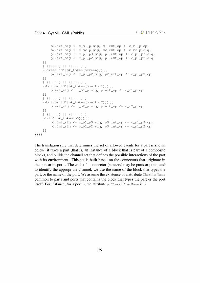
D22.4 - SysML–CML (Public)
m1.ext_sig <- c_m1_p.sig, m1.ext_op <- c_m1_p.op,m2.ext_sig <- c_m2_p.sig, m2.ext_op <- c_m2_p.sig,p1.ext_sig <- c_p1_p3.sig, p1.ext_op <- c_p1_p3.sig,p1.ext_sig <- c_p1_p2.sig, p1.ext_op <- c_p1_p2.sig
]][ {|...|} || {|...|} ](Screen(id^[mk_token(screen)])[[
p2.ext_sig <- c_p1_p2.sig, p2.ext_op <- c_p1_p2.op]][ {|...|} || {|...|} ](Monitor(id^[mk_token(monitor1)])[[
p.ext_sig <- c_m1_p.sig, p.ext_op <- c_m1_p.op]][ {|...|} || {|...|} ](Monitor(id^[mk_token(monitor2)])[[
p.ext_sig <- c_m2_p.sig, p.ext_op <- c_m2_p.op]][ {|...|} || {|...|} ]p3(id^[mk_token(p3)])[[
p3.int_sig <- c_p1_p3.sig, p3.int_op <- c_p1_p3.op,p3.int_sig <- c_p1_p2.sig, p3.int_op <- c_p1_p2.op
]]))))
The translation rule that determines the set of allowed events for a part is shownbelow; it takes a part (that is, an instance of a block that is part of a compositeblock), and builds the channel set that defines the possible interactions of the partwith its environment. This set is built based on the connectors that originate inthe part or its ports. The ends of a connector (c.Ends) may be parts or ports, andto identify the appropriate channel, we use the name of the block that types thepart, or the name of the port. We assume the existence of a attribute ClassifierNamecommon to parts and ports that contains the block that types the part or the portitself. For instance, for a port p, the attribute p.ClassifierName is p.
75
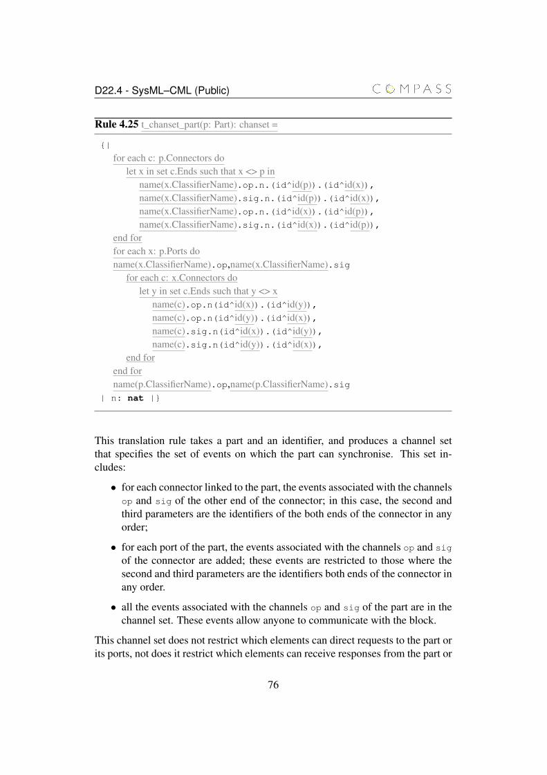
D22.4 - SysML–CML (Public)
Rule 4.25 t_chanset_part(p: Part): chanset =
{|
for each c: p.Connectors dolet x in set c.Ends such that x <> p in
name(x.ClassifierName).op.n.(id^id(p)).(id^id(x)),name(x.ClassifierName).sig.n.(id^id(p)).(id^id(x)),name(x.ClassifierName).op.n.(id^id(x)).(id^id(p)),name(x.ClassifierName).sig.n.(id^id(x)).(id^id(p)),
end forfor each x: p.Ports doname(x.ClassifierName).op,name(x.ClassifierName).sig
for each c: x.Connectors dolet y in set c.Ends such that y <> x
name(c).op.n(id^id(x)).(id^id(y)),name(c).op.n(id^id(y)).(id^id(x)),name(c).sig.n(id^id(x)).(id^id(y)),name(c).sig.n(id^id(y)).(id^id(x)),
end forend forname(p.ClassifierName).op,name(p.ClassifierName).sig
| n: nat |}
This translation rule takes a part and an identifier, and produces a channel setthat specifies the set of events on which the part can synchronise. This set in-cludes:
• for each connector linked to the part, the events associated with the channelsop and sig of the other end of the connector; in this case, the second andthird parameters are the identifiers of the both ends of the connector in anyorder;
• for each port of the part, the events associated with the channels op and sig
of the connector are added; these events are restricted to those where thesecond and third parameters are the identifiers both ends of the connector inany order.
• all the events associated with the channels op and sig of the part are in thechannel set. These events allow anyone to communicate with the block.
This channel set does not restrict which elements can direct requests to the part orits ports, not does it restrict which elements can receive responses from the part or
76
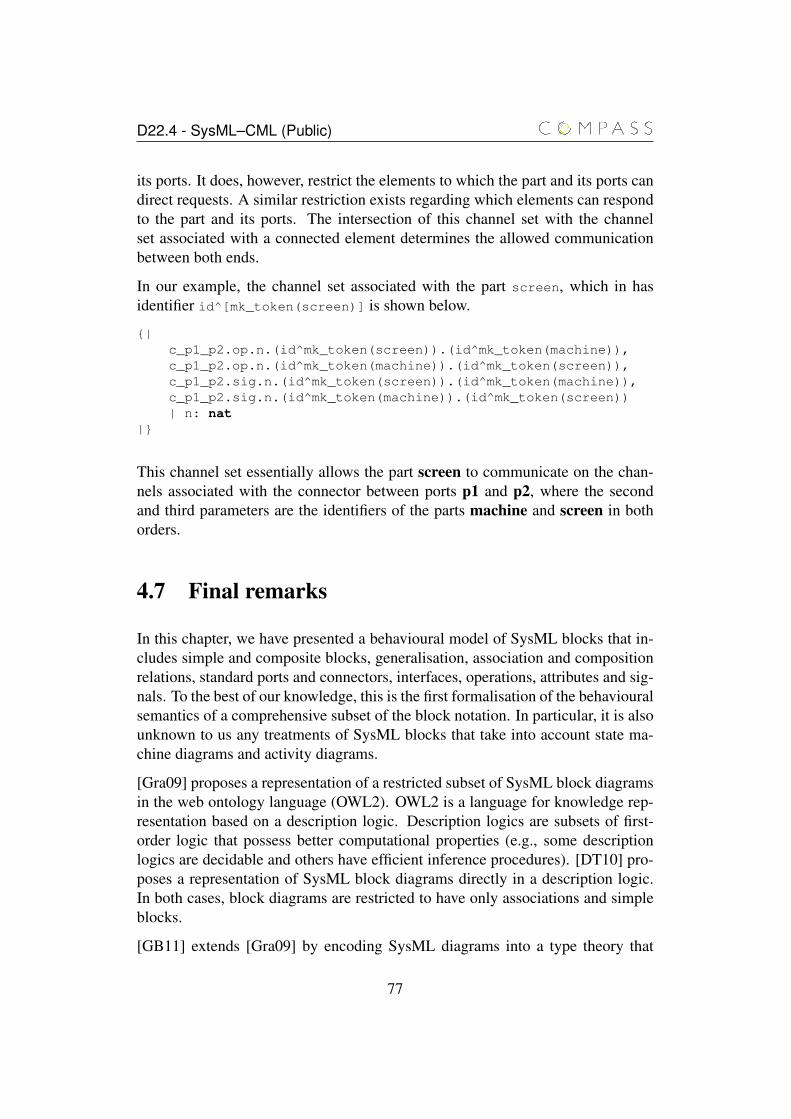
D22.4 - SysML–CML (Public)
its ports. It does, however, restrict the elements to which the part and its ports candirect requests. A similar restriction exists regarding which elements can respondto the part and its ports. The intersection of this channel set with the channelset associated with a connected element determines the allowed communicationbetween both ends.
In our example, the channel set associated with the part screen, which in hasidentifier id^[mk_token(screen)] is shown below.
{|c_p1_p2.op.n.(id^mk_token(screen)).(id^mk_token(machine)),c_p1_p2.op.n.(id^mk_token(machine)).(id^mk_token(screen)),c_p1_p2.sig.n.(id^mk_token(screen)).(id^mk_token(machine)),c_p1_p2.sig.n.(id^mk_token(machine)).(id^mk_token(screen))| n: nat
|}
This channel set essentially allows the part screen to communicate on the chan-nels associated with the connector between ports p1 and p2, where the secondand third parameters are the identifiers of the parts machine and screen in bothorders.
4.7 Final remarks
In this chapter, we have presented a behavioural model of SysML blocks that in-cludes simple and composite blocks, generalisation, association and compositionrelations, standard ports and connectors, interfaces, operations, attributes and sig-nals. To the best of our knowledge, this is the first formalisation of the behaviouralsemantics of a comprehensive subset of the block notation. In particular, it is alsounknown to us any treatments of SysML blocks that take into account state ma-chine diagrams and activity diagrams.
[Gra09] proposes a representation of a restricted subset of SysML block diagramsin the web ontology language (OWL2). OWL2 is a language for knowledge rep-resentation based on a description logic. Description logics are subsets of first-order logic that possess better computational properties (e.g., some descriptionlogics are decidable and others have efficient inference procedures). [DT10] pro-poses a representation of SysML block diagrams directly in a description logic.In both cases, block diagrams are restricted to have only associations and simpleblocks.
[GB11] extends [Gra09] by encoding SysML diagrams into a type theory that
77
D22.4 - SysML–CML (Public)
axiomatises block diagram notions of types, properties and operators. Block def-inition diagrams and internal block diagrams are covered, but dynamic aspects ofSysML diagrams are not.
All these works focus on generating a set of axioms that specify a system basedon a SysML diagram, and then using the existing techniques for the underlyinglogic to check properties such as consistency. Although [GB11] describe modelrefinement as theory refinement (that is, modification of the knowledge base aim-ing at achieving consistency), it does not elaborate on the topic, and it is not clearwhat properties are preserved by this notion of refinement.
78
Chapter 5
State machine diagrams
In this chapter, we present the formalisation of SysML state machine diagramsin the form of a set of translation rules. This semantics covers simple, non-orthogonal and orthogonal composite states (and regions), completion and non-completion transitions (including interlevel transitions), final states, initial, junc-tion, join and fork pseudostates, signal and call events, and deferred events.
The overall structure of our models is shown in Figure 5.1. The model of the statemachine diagram is a process formed by the parallel composition of two other pro-cesses: controller and internal state machine. Similarly to the processes that modelblocks, the processes that model a state machine and its parts are parametrised byan identifier.
The controller process interacts with the environment through the channel addeventand with the internal state machine process through the channel inevent andconsumed. This process receives events from the environment (e.g., the blockprocess as described in the previous chapter), and assigns one event at time to beprocessed by the state machine. This process is formed by an event pool and aqueue of deferred events, and models the priorities between normal and deferredevents.
The internal state machine process models the behaviour of the state machinewhen processing a particular event (supplied by the controller); it takes an eventfrom the controller through the channel inevent and informs the controller whetherthe event has been successfully consumed or not, or whether it has been deferred.The state machine itself, and each state, region, final state, transition (includingintermediate junction pseudostates), join pseudostate and fork pseudostate (in-cluding the transitions connected to them) generate CML actions in the internalstate machine process.
79

D22.4 - SysML–CML (Public)
In particular, each state produces six actions, each region and final state producesfive actions, each transition produces a single action, and each join and fork pseu-dostate produce a single action. Initial pseudostates do not produce independentactions, contributing to the definition of states and regions. The overall behaviourof the internal state machine process is defined as the parallel composition of theseactions, with the internal communications hidden.
Figure 5.1: Overview of the model of state machines.
The interaction between states and non-completion transitions (i.e., triggerlesstransitions that are executed when a state execution terminates) is modelled bya two phase communication protocol. In the first phase, the event being treatedis transmitted to all transitions and enabled transitions (that is, transitions whosetrigger, if not empty, contains the event and whose guard evaluates to true) prepareto execute or be cancelled (if a conflict occurs). Non-enabled transitions simplywait to restart. In this phase, conflicting transitions (multiple enabled transitionsfrom a common state) are non-deterministically cancelled until a single one re-mains. In the second phase, when all transitions are either waiting to restart orexecute, the machine request that all transitions proceed and waits for them toterminate.
The translation rules for state machine diagrams rely mostly on the informationavailable through the SysML meta-model, but some new information needs to be
80
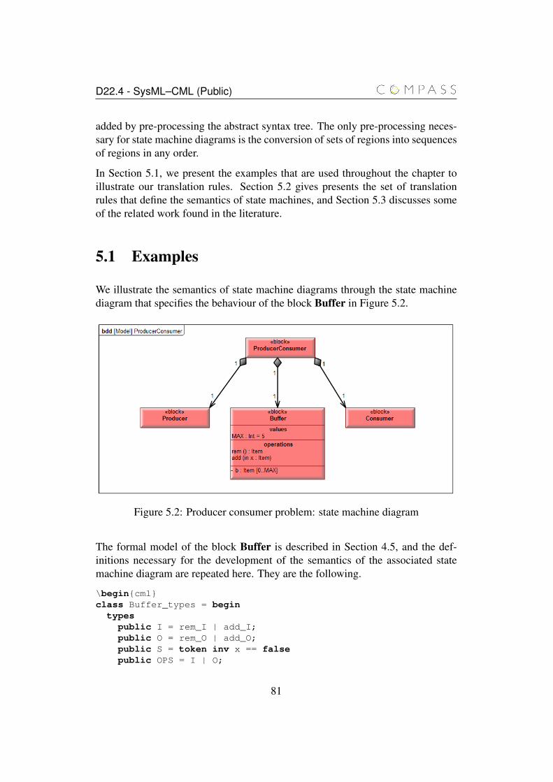
D22.4 - SysML–CML (Public)
added by pre-processing the abstract syntax tree. The only pre-processing neces-sary for state machine diagrams is the conversion of sets of regions into sequencesof regions in any order.
In Section 5.1, we present the examples that are used throughout the chapter toillustrate our translation rules. Section 5.2 gives presents the set of translationrules that define the semantics of state machines, and Section 5.3 discusses someof the related work found in the literature.
5.1 Examples
We illustrate the semantics of state machine diagrams through the state machinediagram that specifies the behaviour of the block Buffer in Figure 5.2.
Figure 5.2: Producer consumer problem: state machine diagram
The formal model of the block Buffer is described in Section 4.5, and the def-initions necessary for the development of the semantics of the associated statemachine diagram are repeated here. They are the following.
\begin{cml}class Buffer_types = begin
typespublic I = rem_I | add_I;public O = rem_O | add_O;public S = token inv x == falsepublic OPS = I | O;
81
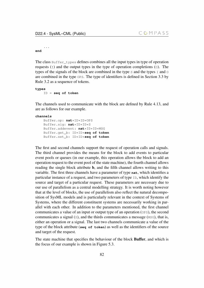
D22.4 - SysML–CML (Public)
...end
The class Buffer_types defines combines all the input types in type of operationrequests (I) and the output types in the type of operation completions (O). Thetypes of the signals of the block are combined in the type S and the types I and O
are combined in the type OPS. The type of identifiers is defined in Section 3.3 byRule 3.2 as a sequence of tokens.
typesID = seq of token
The channels used to communicate with the block are defined by Rule 4.13, andare as follows for our example.
channelsBuffer.op: nat*ID*ID*OPSBuffer.sig: nat*ID*ID*SBuffer.addevent: nat*ID*ID*MSGBuffer.get_b: ID*ID*seq of tokenBuffer.set_b: ID*ID*seq of token
The first and second channels support the request of operation calls and signals.The third channel provides the means for the block to add events to particularevent pools or queues (in our example, this operation allows the block to add anoperation request to the event pool of the state machine), the fourth channel allowsreading the single block attribute b, and the fifth channel allows writing to thisvariable. The first three channels have a parameter of type nat, which identifies aparticular instance of a request, and two parameters of type ID, which identify thesource and target of a particular request. These parameters are necessary due toour use of parallelism as a central modelling strategy. It is worth noting howeverthat at the level of blocks, the use of parallelism also reflect the natural decompo-sition of SysML models and is particularly relevant in the context of Systems ofSystems, where the different constituent systems are necessarily working in par-allel with each other. In addition to the parameters mentioned, the first channelcommunicates a value of an input or output type of an operation (OPS), the secondcommunicates a signal (S), and the thirds communicates a message (MSG), that is,either an operation or a signal. The last two channels communicate a value of thetype of the block attribute (seq of token) as well as the identifiers of the sourceand target of the request.
The state machine that specifies the behaviour of the block Buffer, and which isthe focus of our example is shown in Figure 5.3.
82
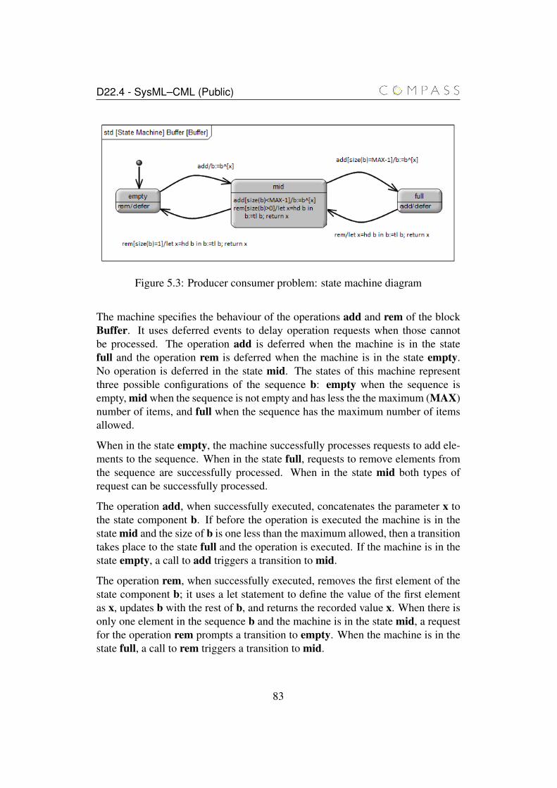
D22.4 - SysML–CML (Public)
Figure 5.3: Producer consumer problem: state machine diagram
The machine specifies the behaviour of the operations add and rem of the blockBuffer. It uses deferred events to delay operation requests when those cannotbe processed. The operation add is deferred when the machine is in the statefull and the operation rem is deferred when the machine is in the state empty.No operation is deferred in the state mid. The states of this machine representthree possible configurations of the sequence b: empty when the sequence isempty, mid when the sequence is not empty and has less the the maximum (MAX)number of items, and full when the sequence has the maximum number of itemsallowed.
When in the state empty, the machine successfully processes requests to add ele-ments to the sequence. When in the state full, requests to remove elements fromthe sequence are successfully processed. When in the state mid both types ofrequest can be successfully processed.
The operation add, when successfully executed, concatenates the parameter x tothe state component b. If before the operation is executed the machine is in thestate mid and the size of b is one less than the maximum allowed, then a transitiontakes place to the state full and the operation is executed. If the machine is in thestate empty, a call to add triggers a transition to mid.
The operation rem, when successfully executed, removes the first element of thestate component b; it uses a let statement to define the value of the first elementas x, updates b with the rest of b, and returns the recorded value x. When there isonly one element in the sequence b and the machine is in the state mid, a requestfor the operation rem prompts a transition to empty. When the machine is in thestate full, a call to rem triggers a transition to mid.
83
D22.4 - SysML–CML (Public)
Figure 5.4: Example extracted from [FMS11]
Since our first example contains only simple states, we use other self-containedexamples (that is, examples that do not require the model of an associated block)to illustrate the semantics of language features not covered in the previous exam-ple. In particular, we use the example shown in Figure 5.4 and extracted from[FMS11] to illustrate the semantics of orthogonal states and regions. A particu-larly interesting aspect of this example is the treatment of transition priorities, thatis, when multiple transitions in different levels of the hierarchy can be triggered,priorities are used to determine which one is effectively triggered.
This example contains six states, of which state 1.1.1, state 1.1.2, state 1.2.1,state 1.2.2 and state 2 are simple states. The only composite state, state 1, hastwo orthogonal regions. The first contains states state 1.1.1 and state 1.1.2, andthe second contains states state 1.2.1 and state 1.2.2.
There are six transitions: three of them are initial transitions, and the remainingare all triggered by the signal sig1, but with different guards. The transition t1from state 1 to state 2 has guard x <= 0, t2 from state 1.1.1 to state 1.1.2 hasguard x >= 0, and t3 from state 1.2.1 to state 1.2.2 has guard x >= 1.
The behaviour of this chart is as follows. On initialisation, the initial transitionleads to state 1 being entered, and consequently its two regions are also entered.The initial transitions in the regions lead to the states state 1.1.1 and state 1.2.1 tobe entered. At this point, the machine waits for an event to react. In our example,we will assume that this machine can receive two events: sig1 and sig2. Noticethat only sig1 causes the machine to react.
From its initial configuration, if an event sig1 is received, depending on the valueof the state variable x, specific transitions may be triggered. The deeper a transi-tion is in the state hierarchy, the higher its priority. In our example this manifests
84
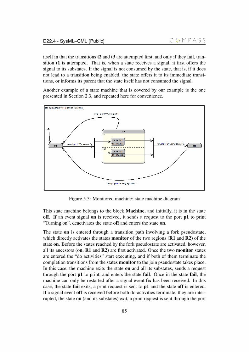
D22.4 - SysML–CML (Public)
itself in that the transitions t2 and t3 are attempted first, and only if they fail, tran-sition t1 is attempted. That is, when a state receives a signal, it first offers thesignal to its substates. If the signal is not consumed by the state, that is, if it doesnot lead to a transition being enabled, the state offers it to its immediate transi-tions, or informs its parent that the state itself has not consumed the signal.
Another example of a state machine that is covered by our example is the onepresented in Section 2.3, and repeated here for convenience.
Figure 5.5: Monitored machine: state machine diagram
This state machine belongs to the block Machine, and initially, it is in the stateoff. If an event signal on is received, it sends a request to the port p1 to print“Turning on”, deactivates the state off and enters the state on.
The state on is entered through a transition path involving a fork pseudostate,which directly activates the states monitor of the two regions (R1 and R2) of thestate on. Before the states reached by the fork pseudostate are activated, however,all its ancestors (on, R1 and R2) are first activated. Once the two monitor statesare entered the “do activities” start executing, and if both of them terminate thecompletion transitions from the states monitor to the join pseudostate takes place.In this case, the machine exits the state on and all its substates, sends a requestthrough the port p1 to print, and enters the state fail. Once in the state fail, themachine can only be restarted after a signal event fix has been received. In thiscase, the state fail exits, a print request is sent to p1 and the state off is entered.If a signal event off is received before both do-activities terminate, they are inter-rupted, the state on (and its substates) exit, a print request is sent through the port
85
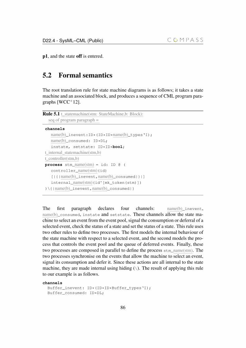
D22.4 - SysML–CML (Public)
p1, and the state off is entered.
5.2 Formal semantics
The root translation rule for state machine diagrams is as follows; it takes a statemachine and an associated block, and produces a sequence of CML program para-graphs [WCC+12].
Rule 5.1 t_statemachine(stm: StateMachine,b: Block):seq of program paragraph =
channels
name(b)_inevent:ID*(ID*ID*name(b)_types‘I);name(b)_consumed: ID*DL;
instate, setstate: ID*ID*bool;
t_internal_statemachine(stm,b)t_controller(stm,b)process stm_name(stm) = id: ID @ (
controller_name(stm)(id)[|{|name(b)_inevent,name(b)_consumed|}|]internal_name(stm)(id^[mk_token(stm)])
)\{|name(b)_inevent,name(b)_consumed|}
The first paragraph declares four channels: name(b)_inevent,name(b)_consumed, instate and setstate. These channels allow the state ma-chine to select an event from the event pool, signal the consumption or deferral of aselected event, check the status of a state and set the status of a state. This rule usestwo other rules to define two processes. The first models the internal behaviour ofthe state machine with respect to a selected event, and the second models the pro-cess that controls the event pool and the queue of deferred events. Finally, thesetwo processes are composed in parallel to define the process stm_name(stm). Thetwo processes synchronise on the events that allow the machine to select an event,signal its consumption and defer it. Since these actions are all internal to the statemachine, they are made internal using hiding (\). The result of applying this ruleto our example is as follows.
channelsBuffer_inevent: ID*(ID*ID*Buffer_types‘I);Buffer_consumed: ID*DL;
86
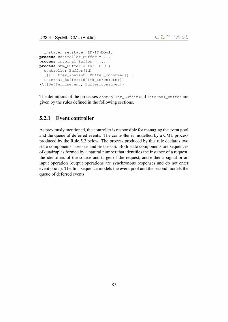
D22.4 - SysML–CML (Public)
instate, setstate: ID*ID*bool;process controller_Buffer = ...process internal_Buffer = ...process stm_Buffer = id: ID @ (
controller_Buffer(id)[|{|Buffer_inevent, Buffer_consumed|}|]internal_Buffer(id^[mk_token(stm)])
)\{|Buffer_inevent, Buffer_consumed|}
The definitions of the processes controller_Buffer and internal_Buffer aregiven by the rules defined in the following sections.
5.2.1 Event controller
As previously mentioned, the controller is responsible for managing the event pooland the queue of deferred events. The controller is modelled by a CML processproduced by the Rule 5.2 below. The process produced by this rule declares twostate components: events and deferred. Both state components are sequencesof quadruples formed by a natural number that identifies the instance of a request,the identifiers of the source and target of the request, and either a signal or aninput operation (output operations are synchronous responses and do not enterevent pools). The first sequence models the event pool and the second models thequeue of deferred events.
87
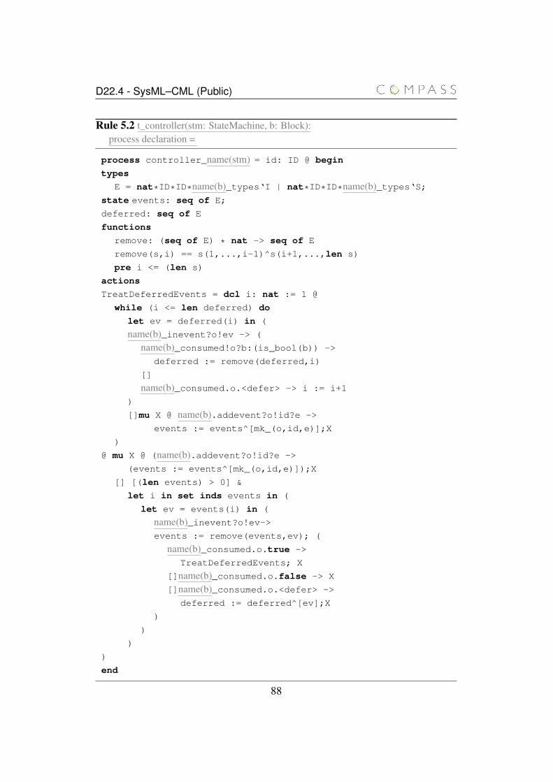
D22.4 - SysML–CML (Public)
Rule 5.2 t_controller(stm: StateMachine, b: Block):process declaration =
process controller_name(stm) = id: ID @ begin
types
E = nat*ID*ID*name(b)_types‘I | nat*ID*ID*name(b)_types‘S;state events: seq of E;
deferred: seq of E
functions
remove: (seq of E) * nat -> seq of E
remove(s,i) == s(1,...,i-1)^s(i+1,...,len s)
pre i <= (len s)
actions
TreatDeferredEvents = dcl i: nat := 1 @
while (i <= len deferred) do
let ev = deferred(i) in (
name(b)_inevent?o!ev -> (
name(b)_consumed!o?b:(is_bool(b)) ->
deferred := remove(deferred,i)
[]
name(b)_consumed.o.<defer> -> i := i+1
)
[]mu X @ name(b).addevent?o!id?e ->
events := events^[mk_(o,id,e)];X
)
@ mu X @ (name(b).addevent?o!id?e ->
(events := events^[mk_(o,id,e)]);X
[] [(len events) > 0] &
let i in set inds events in (
let ev = events(i) in (
name(b)_inevent?o!ev->events := remove(events,ev); (
name(b)_consumed.o.true ->
TreatDeferredEvents; X
[]name(b)_consumed.o.false -> X
[]name(b)_consumed.o.<defer> ->
deferred := deferred^[ev];X
)
)
)
)
end
88
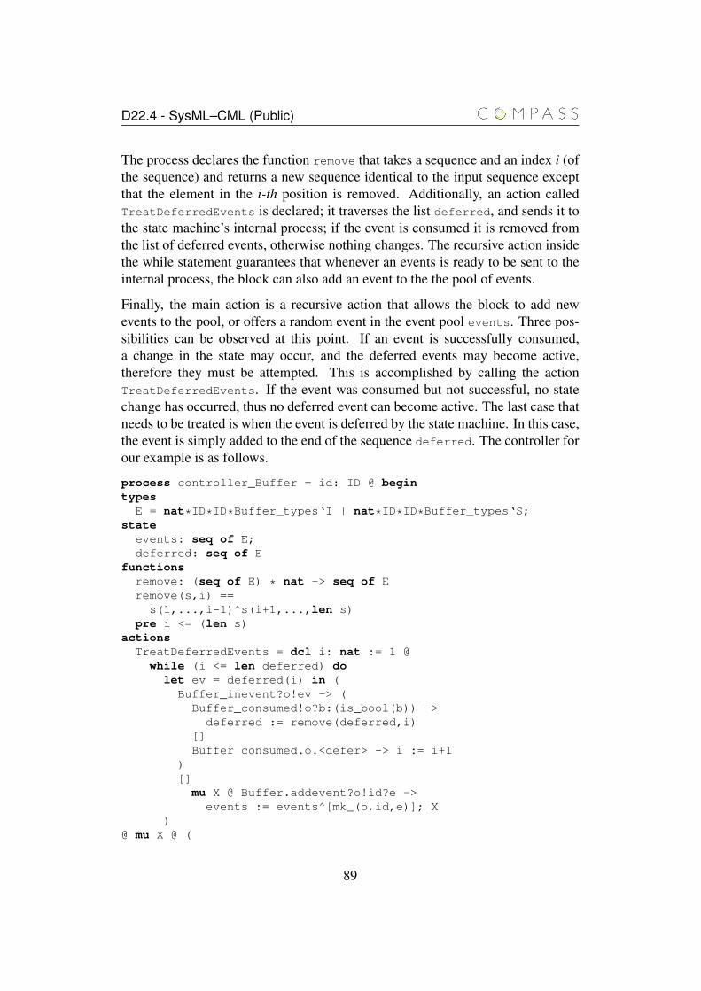
D22.4 - SysML–CML (Public)
The process declares the function remove that takes a sequence and an index i (ofthe sequence) and returns a new sequence identical to the input sequence exceptthat the element in the i-th position is removed. Additionally, an action calledTreatDeferredEvents is declared; it traverses the list deferred, and sends it tothe state machine’s internal process; if the event is consumed it is removed fromthe list of deferred events, otherwise nothing changes. The recursive action insidethe while statement guarantees that whenever an events is ready to be sent to theinternal process, the block can also add an event to the the pool of events.
Finally, the main action is a recursive action that allows the block to add newevents to the pool, or offers a random event in the event pool events. Three pos-sibilities can be observed at this point. If an event is successfully consumed,a change in the state may occur, and the deferred events may become active,therefore they must be attempted. This is accomplished by calling the actionTreatDeferredEvents. If the event was consumed but not successful, no statechange has occurred, thus no deferred event can become active. The last case thatneeds to be treated is when the event is deferred by the state machine. In this case,the event is simply added to the end of the sequence deferred. The controller forour example is as follows.
process controller_Buffer = id: ID @ begintypes
E = nat*ID*ID*Buffer_types‘I | nat*ID*ID*Buffer_types‘S;state
events: seq of E;deferred: seq of E
functionsremove: (seq of E) * nat -> seq of Eremove(s,i) ==
s(1,...,i-1)^s(i+1,...,len s)pre i <= (len s)
actionsTreatDeferredEvents = dcl i: nat := 1 @
while (i <= len deferred) dolet ev = deferred(i) in (
Buffer_inevent?o!ev -> (Buffer_consumed!o?b:(is_bool(b)) ->
deferred := remove(deferred,i)[]Buffer_consumed.o.<defer> -> i := i+1
)[]
mu X @ Buffer.addevent?o!id?e ->events := events^[mk_(o,id,e)]; X
)@ mu X @ (
89
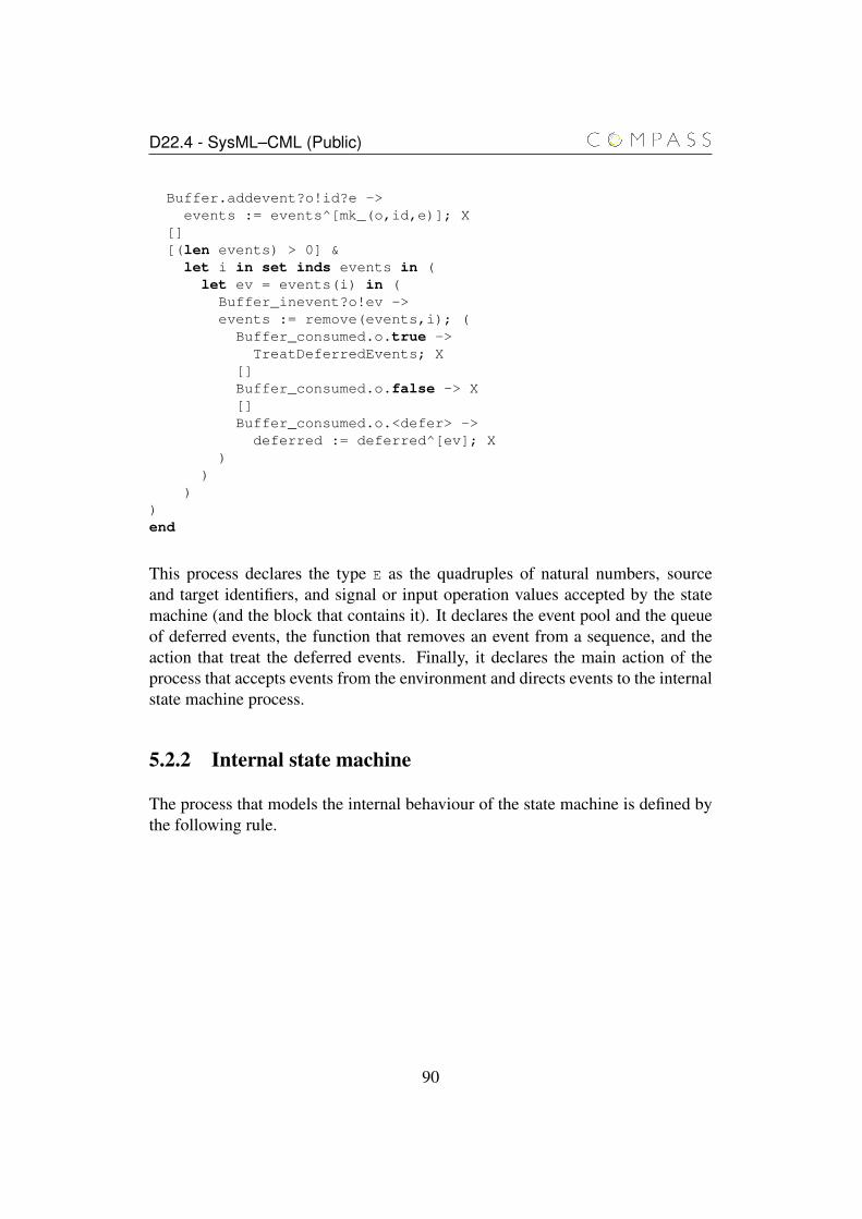
D22.4 - SysML–CML (Public)
Buffer.addevent?o!id?e ->events := events^[mk_(o,id,e)]; X
[][(len events) > 0] &
let i in set inds events in (let ev = events(i) in (Buffer_inevent?o!ev ->events := remove(events,i); (
Buffer_consumed.o.true ->TreatDeferredEvents; X
[]Buffer_consumed.o.false -> X[]Buffer_consumed.o.<defer> ->
deferred := deferred^[ev]; X)
))
)end
This process declares the type E as the quadruples of natural numbers, sourceand target identifiers, and signal or input operation values accepted by the statemachine (and the block that contains it). It declares the event pool and the queueof deferred events, the function that removes an event from a sequence, and theaction that treat the deferred events. Finally, it declares the main action of theprocess that accepts events from the environment and directs events to the internalstate machine process.
5.2.2 Internal state machine
The process that models the internal behaviour of the state machine is defined bythe following rule.
90
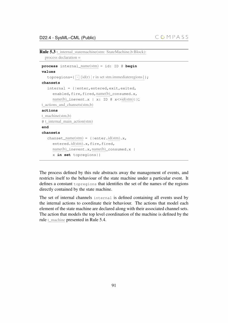
D22.4 - SysML–CML (Public)
Rule 5.3 t_internal_statemachine(stm: StateMachine,b:Block):process declaration =
process internal_name(stm) = id: ID @ begin
values
topregions={ , {id(r) | r in set stm.immediateregions}};chansets
internal = {|enter,entered,exit,exited,
enabled,fire,fired,name(b)_consumed.x,name(b)_inevent.x | x: ID @ x<>id(stm)|};
t_actions_and_chansets(stm,b)actions
t_machine(stm,b)@ t_internal_main_action(stm)end
chansets
chanset_name(stm) = {|enter.id(stm).x,entered.id(stm).x,fire,fired,name(b)_inevent.x,name(b)_consumed.x |
x in set topregions|}
The process defined by this rule abstracts away the management of events, andrestricts itself to the behaviour of the state machine under a particular event. Itdefines a constant topregions that identifies the set of the names of the regionsdirectly contained by the state machine.
The set of internal channels internal is defined containing all events used bythe internal actions to coordinate their behaviour. The actions that model eachelement of the state machine are declared along with their associated channel sets.The action that models the top level coordination of the machine is defined by therule t_machine presented in Rule 5.4.
91
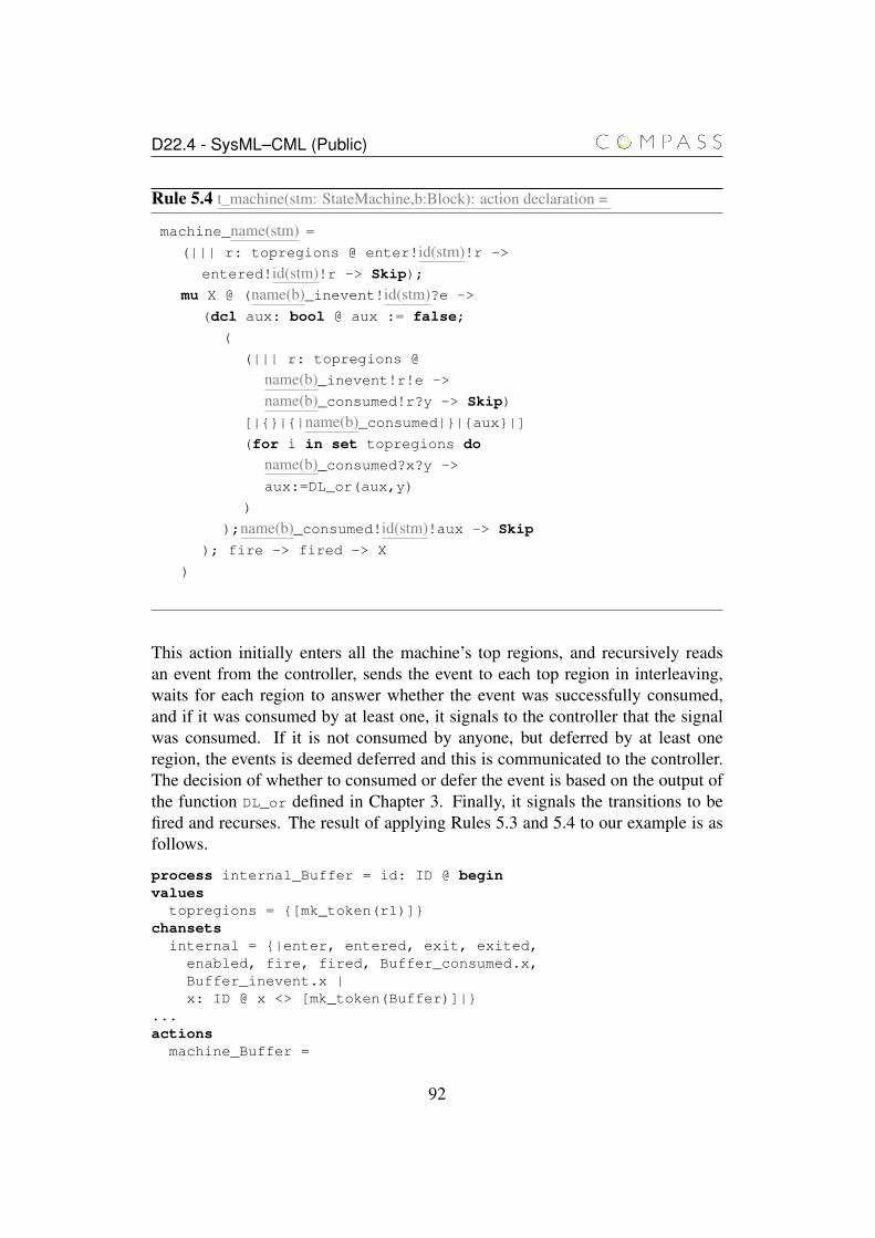
D22.4 - SysML–CML (Public)
Rule 5.4 t_machine(stm: StateMachine,b:Block): action declaration =
machine_name(stm) =(||| r: topregions @ enter!id(stm)!r ->
entered!id(stm)!r -> Skip);
mu X @ (name(b)_inevent!id(stm)?e ->
(dcl aux: bool @ aux := false;
(
(||| r: topregions @
name(b)_inevent!r!e ->
name(b)_consumed!r?y -> Skip)
[|{}|{|name(b)_consumed|}|{aux}|](for i in set topregions do
name(b)_consumed?x?y ->
aux:=DL_or(aux,y)
)
);name(b)_consumed!id(stm)!aux -> Skip
); fire -> fired -> X
)
This action initially enters all the machine’s top regions, and recursively readsan event from the controller, sends the event to each top region in interleaving,waits for each region to answer whether the event was successfully consumed,and if it was consumed by at least one, it signals to the controller that the signalwas consumed. If it is not consumed by anyone, but deferred by at least oneregion, the events is deemed deferred and this is communicated to the controller.The decision of whether to consumed or defer the event is based on the output ofthe function DL_or defined in Chapter 3. Finally, it signals the transitions to befired and recurses. The result of applying Rules 5.3 and 5.4 to our example is asfollows.
process internal_Buffer = id: ID @ beginvalues
topregions = {[mk_token(r1)]}chansets
internal = {|enter, entered, exit, exited,enabled, fire, fired, Buffer_consumed.x,Buffer_inevent.x |x: ID @ x <> [mk_token(Buffer)]|}
...actions
machine_Buffer =
92

D22.4 - SysML–CML (Public)
(||| r: topregions @enter![mk_token(Buffer)]!r ->entered![mk_token(Buffer)]!r -> Skip);
mu X @ (Buffer_inevent![mk_token(Buffer)]?e ->(dcl aux: bool @ aux := false;
((||| r: topregions @
Buffer_inevent!r!e ->Buffer_consumed!r?y -> Skip)
[|{}|{|Buffer_consumed|}|{aux}|](for i in set topregions do
Buffer_consumed?x?y ->aux:=DL_or(aux,y)
));Buffer_consumed![mk_token(Buffer)]!aux-> Skip
); fire -> fired -> X)
@ ...endchansets
chanset_Buffer = {|enter.[mk_token(Buffer)].x,entered.[mk_token(Buffer)].x, Buffer_inevent.x,Buffer_consumed.x, fire, fired| x in set topregions|}
This process declares a constant that identifies the top regions ([mk_token(r1)]),and the set of internal channels. If then declares the actions that model the ele-ments of the diagram (e.g., states) as well as the associated channel sets. Next,it declares the action that specifies the coordination of events and transitions. Fi-nally, it completes the process by defining the main action (elided here), and de-clares the set of internal channels.
The elided parts are completed by calls to other rules; the result of the applicationof those rules is illustrated together with the rule definition.
The next rule produces all the action declarations for the process that models theinternal behaviour of the state machine.
93
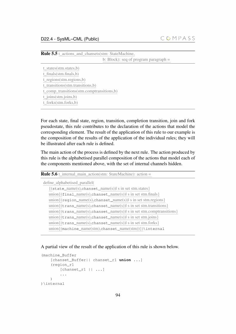
D22.4 - SysML–CML (Public)
Rule 5.5 t_actions_and_chansets(stm: StateMachine,b: Block): seq of program paragraph =
t_states(stm.states,b)t_finals(stm.finals,b)t_regions(stm.regions,b)t_transitions(stm.transitions,b)t_comp_transitions(stm.comptransitions,b)t_joins(stm.joins,b)t_forks(stm.forks,b)
For each state, final state, region, transition, completion transition, join and forkpseudostate, this rule contributes to the declaration of the actions that model thecorresponding element. The result of the application of this rule to our example isthe composition of the results of the application of the individual rules; they willbe illustrated after each rule is defined.
The main action of the process is defined by the next rule. The action produced bythis rule is the alphabetised parallel composition of the actions that model each ofthe components mentioned above, with the set of internal channels hidden.
Rule 5.6 t_internal_main_action(stm: StateMachine): action =
define_alphabetised_parallel({(state_name(s),chanset_name(s))| s in set stm.states}union{(final_name(s),chanset_name(s))| s in set stm.finals}union{(region_name(s),chanset_name(s))| s in set stm.regions}union{(trans_name(s),chanset_name(s))| s in set stm.transitions}union{(trans_name(s),chanset_name(s))| s in set stm.comptransitions}union{(trans_name(s),chanset_name(s))| s in set stm.joins}union{(trans_name(s),chanset_name(s))| s in set stm.forks}union{(machine_name(stm),chanset_name(stm))})\internal
A partial view of the result of the application of this rule is shown below.
(machine_Buffer[chanset_Buffer|| chanset_r1 union ...](region_r1
[chanset_r1 || ...]...
))\internal
94
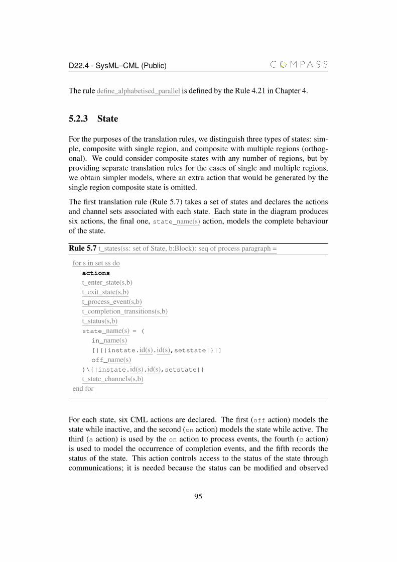
D22.4 - SysML–CML (Public)
The rule define_alphabetised_parallel is defined by the Rule 4.21 in Chapter 4.
5.2.3 State
For the purposes of the translation rules, we distinguish three types of states: sim-ple, composite with single region, and composite with multiple regions (orthog-onal). We could consider composite states with any number of regions, but byproviding separate translation rules for the cases of single and multiple regions,we obtain simpler models, where an extra action that would be generated by thesingle region composite state is omitted.
The first translation rule (Rule 5.7) takes a set of states and declares the actionsand channel sets associated with each state. Each state in the diagram producessix actions, the final one, state_name(s) action, models the complete behaviourof the state.
Rule 5.7 t_states(ss: set of State, b:Block): seq of process paragraph =
for s in set ss doactions
t_enter_state(s,b)t_exit_state(s,b)t_process_event(s,b)t_completion_transitions(s,b)t_status(s,b)state_name(s) = (
in_name(s)[|{|instate.id(s).id(s),setstate|}|]off_name(s)
)\{|instate.id(s).id(s),setstate|}t_state_channels(s,b)
end for
For each state, six CML actions are declared. The first (off action) models thestate while inactive, and the second (on action) models the state while active. Thethird (a action) is used by the on action to process events, the fourth (c action)is used to model the occurrence of completion events, and the fifth records thestatus of the state. This action controls access to the status of the state throughcommunications; it is needed because the status can be modified and observed
95
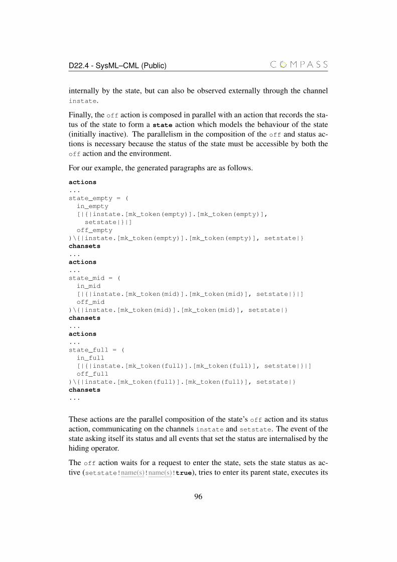
D22.4 - SysML–CML (Public)
internally by the state, but can also be observed externally through the channelinstate.
Finally, the off action is composed in parallel with an action that records the sta-tus of the state to form a state action which models the behaviour of the state(initially inactive). The parallelism in the composition of the off and status ac-tions is necessary because the status of the state must be accessible by both theoff action and the environment.
For our example, the generated paragraphs are as follows.
actions...state_empty = (
in_empty[|{|instate.[mk_token(empty)].[mk_token(empty)],
setstate|}|]off_empty
)\{|instate.[mk_token(empty)].[mk_token(empty)], setstate|}chansets...actions...state_mid = (
in_mid[|{|instate.[mk_token(mid)].[mk_token(mid)], setstate|}|]off_mid
)\{|instate.[mk_token(mid)].[mk_token(mid)], setstate|}chansets...actions...state_full = (
in_full[|{|instate.[mk_token(full)].[mk_token(full)], setstate|}|]off_full
)\{|instate.[mk_token(full)].[mk_token(full)], setstate|}chansets...
These actions are the parallel composition of the state’s off action and its statusaction, communicating on the channels instate and setstate. The event of thestate asking itself its status and all events that set the status are internalised by thehiding operator.
The off action waits for a request to enter the state, sets the state status as ac-tive (setstate!name(s)!name(s)!true), tries to enter its parent state, executes its
96
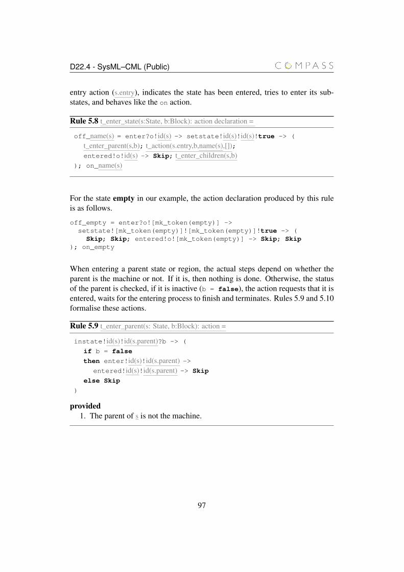
D22.4 - SysML–CML (Public)
entry action (s.entry), indicates the state has been entered, tries to enter its sub-states, and behaves like the on action.
Rule 5.8 t_enter_state(s:State, b:Block): action declaration =
off_name(s) = enter?o!id(s) -> setstate!id(s)!id(s)!true -> (
t_enter_parent(s,b); t_action(s.entry,b,name(s),[]);entered!o!id(s) -> Skip; t_enter_children(s,b)
); on_name(s)
For the state empty in our example, the action declaration produced by this ruleis as follows.
off_empty = enter?o![mk_token(empty)] ->setstate![mk_token(empty)]![mk_token(empty)]!true -> (Skip; Skip; entered!o![mk_token(empty)] -> Skip; Skip
); on_empty
When entering a parent state or region, the actual steps depend on whether theparent is the machine or not. If it is, then nothing is done. Otherwise, the statusof the parent is checked, if it is inactive (b = false), the action requests that it isentered, waits for the entering process to finish and terminates. Rules 5.9 and 5.10formalise these actions.
Rule 5.9 t_enter_parent(s: State, b:Block): action =
instate!id(s)!id(s.parent)?b -> (
if b = false
then enter!id(s)!id(s.parent) ->entered!id(s)!id(s.parent) -> Skip
else Skip
)
provided1. The parent of s is not the machine.
97
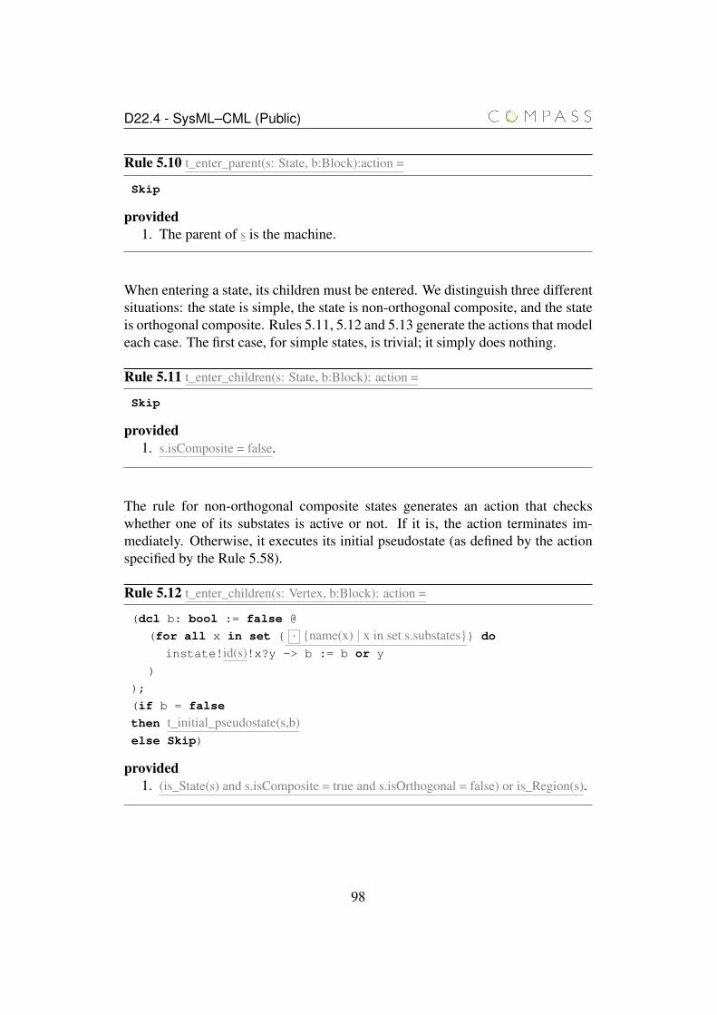
D22.4 - SysML–CML (Public)
Rule 5.10 t_enter_parent(s: State, b:Block):action =
Skip
provided1. The parent of s is the machine.
When entering a state, its children must be entered. We distinguish three differentsituations: the state is simple, the state is non-orthogonal composite, and the stateis orthogonal composite. Rules 5.11, 5.12 and 5.13 generate the actions that modeleach case. The first case, for simple states, is trivial; it simply does nothing.
Rule 5.11 t_enter_children(s: State, b:Block): action =
Skip
provided1. s.isComposite = false.
The rule for non-orthogonal composite states generates an action that checkswhether one of its substates is active or not. If it is, the action terminates im-mediately. Otherwise, it executes its initial pseudostate (as defined by the actionspecified by the Rule 5.58).
Rule 5.12 t_enter_children(s: Vertex, b:Block): action =
(dcl b: bool := false @
(for all x in set { , {name(x) | x in set s.substates}} do
instate!id(s)!x?y -> b := b or y
)
);
(if b = false
then t_initial_pseudostate(s,b)else Skip)
provided1. (is_State(s) and s.isComposite = true and s.isOrthogonal = false) or is_Region(s).
98
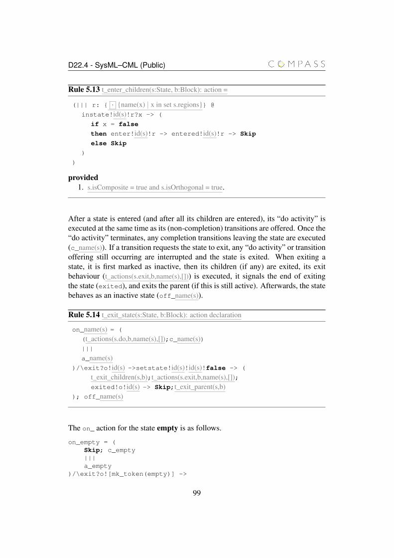
D22.4 - SysML–CML (Public)
Rule 5.13 t_enter_children(s:State, b:Block): action =
(||| r: { , {name(x) | x in set s.regions}} @
instate!id(s)!r?x -> (
if x = false
then enter!id(s)!r -> entered!id(s)!r -> Skip
else Skip
)
)
provided1. s.isComposite = true and s.isOrthogonal = true.
After a state is entered (and after all its children are entered), its “do activity” isexecuted at the same time as its (non-completion) transitions are offered. Once the“do activity” terminates, any completion transitions leaving the state are executed(c_name(s)). If a transition requests the state to exit, any “do activity” or transitionoffering still occurring are interrupted and the state is exited. When exiting astate, it is first marked as inactive, then its children (if any) are exited, its exitbehaviour (t_actions(s.exit,b,name(s),[])) is executed, it signals the end of exitingthe state (exited), and exits the parent (if this is still active). Afterwards, the statebehaves as an inactive state (off_name(s)).
Rule 5.14 t_exit_state(s:State, b:Block): action declaration
on_name(s) = (
(t_actions(s.do,b,name(s),[]);c_name(s))|||
a_name(s))/\exit?o!id(s) ->setstate!id(s)!id(s)!false -> (
t_exit_children(s,b);t_actions(s.exit,b,name(s),[]);exited!o!id(s) -> Skip;t_exit_parent(s,b)
); off_name(s)
The on_ action for the state empty is as follows.
on_empty = (Skip; c_empty|||a_empty
)/\exit?o![mk_token(empty)] ->
99
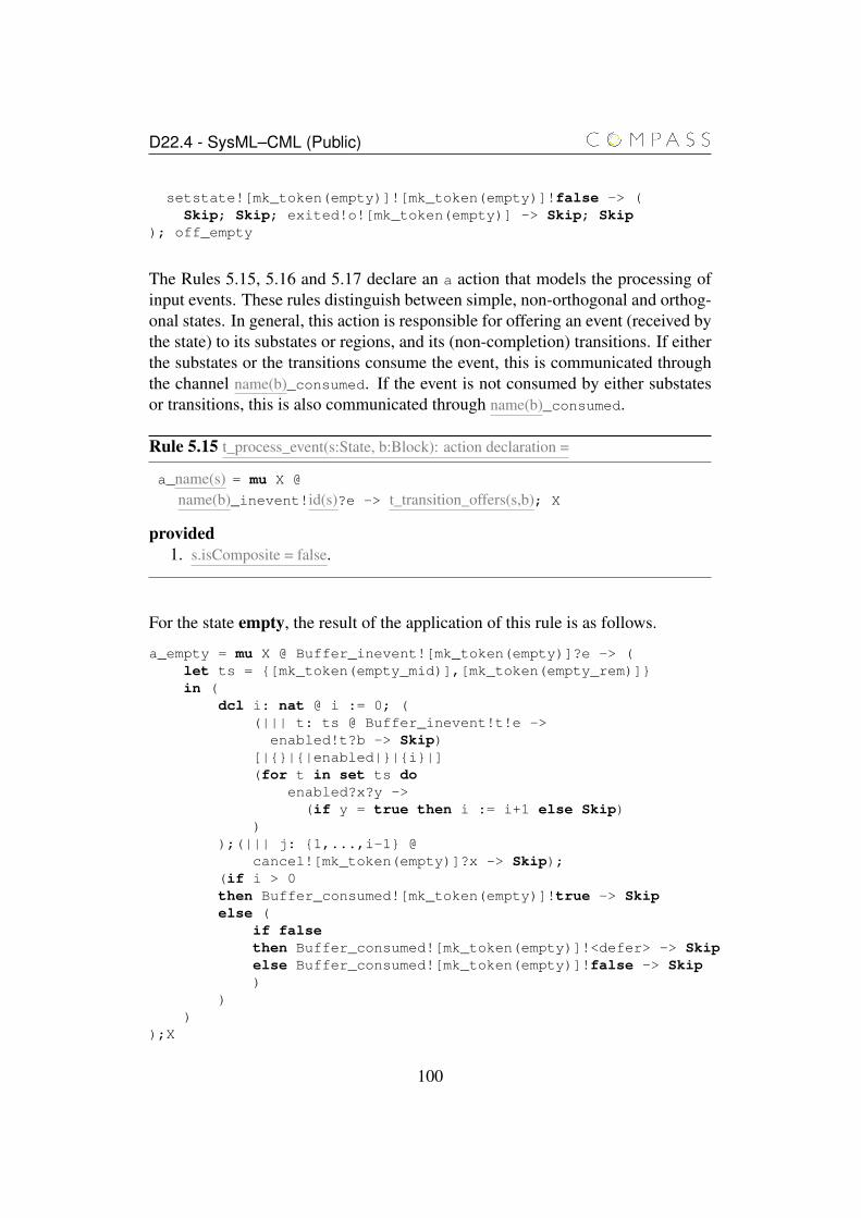
D22.4 - SysML–CML (Public)
setstate![mk_token(empty)]![mk_token(empty)]!false -> (Skip; Skip; exited!o![mk_token(empty)] -> Skip; Skip
); off_empty
The Rules 5.15, 5.16 and 5.17 declare an a action that models the processing ofinput events. These rules distinguish between simple, non-orthogonal and orthog-onal states. In general, this action is responsible for offering an event (received bythe state) to its substates or regions, and its (non-completion) transitions. If eitherthe substates or the transitions consume the event, this is communicated throughthe channel name(b)_consumed. If the event is not consumed by either substatesor transitions, this is also communicated through name(b)_consumed.
Rule 5.15 t_process_event(s:State, b:Block): action declaration =
a_name(s) = mu X @
name(b)_inevent!id(s)?e -> t_transition_offers(s,b); X
provided1. s.isComposite = false.
For the state empty, the result of the application of this rule is as follows.
a_empty = mu X @ Buffer_inevent![mk_token(empty)]?e -> (let ts = {[mk_token(empty_mid)],[mk_token(empty_rem)]}in (
dcl i: nat @ i := 0; ((||| t: ts @ Buffer_inevent!t!e ->
enabled!t?b -> Skip)[|{}|{|enabled|}|{i}|](for t in set ts do
enabled?x?y ->(if y = true then i := i+1 else Skip)
));(||| j: {1,...,i-1} @
cancel![mk_token(empty)]?x -> Skip);(if i > 0then Buffer_consumed![mk_token(empty)]!true -> Skipelse (
if falsethen Buffer_consumed![mk_token(empty)]!<defer> -> Skipelse Buffer_consumed![mk_token(empty)]!false -> Skip)
))
);X
100
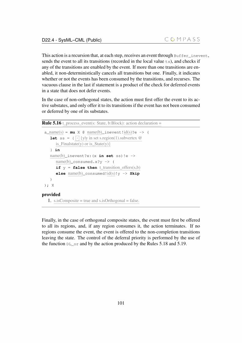
D22.4 - SysML–CML (Public)
This action is a recursion that, at each step, receives an event through Buffer_inevent,sends the event to all its transitions (recorded in the local value ts), and checks ifany of the transitions are enabled by the event. If more than one transitions are en-abled, it non-deterministically cancels all transitions but one. Finally, it indicateswhether or not the events has been consumed by the transitions, and recurses. Thevacuous clause in the last if statement is a product of the check for deferred eventsin a state that does not defer events.
In the case of non-orthogonal states, the action must first offer the event to its ac-tive substates, and only offer it to its transitions if the event has not been consumedor deferred by one of its substates.
Rule 5.16 t_process_event(s: State, b:Block): action declaration =
a_name(s) = mu X @ name(b)_inevent!id(s)?e -> (
let ss = { , {y|y in set s.region(1).subvertex @is_Finalstate(y) or is_State(y)}
} in
name(b)_inevent?x:(x in set ss)!e ->
name(b)_consumed.x?y -> (
if y = false then t_transition_offers(s,b)else name(b)_consumed!id(s)!y -> Skip
)
); X
provided1. s.isComposite = true and s.isOrthogonal = false.
Finally, in the case of orthogonal composite states, the event must first be offeredto all its regions, and, if any region consumes it, the action terminates. If noregions consume the event, the event is offered to the non-completion transitionsleaving the state. The control of the deferral priority is performed by the use ofthe function DL_or and by the action produced by the Rules 5.18 and 5.19.
101
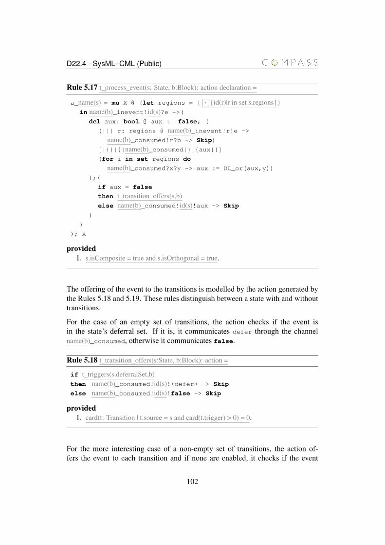
D22.4 - SysML–CML (Public)
Rule 5.17 t_process_event(s: State, b:Block): action declaration =
a_name(s) = mu X @ (let regions = { , {id(r)|r in set s.regions}}in name(b)_inevent!id(s)?e ->(
dcl aux: bool @ aux := false; (
(||| r: regions @ name(b)_inevent!r!e ->
name(b)_consumed!r?b -> Skip)
[|{}|{|name(b)_consumed|}|{aux}|](for i in set regions do
name(b)_consumed?x?y -> aux := DL_or(aux,y))
);(
if aux = false
then t_transition_offers(s,b)else name(b)_consumed!id(s)!aux -> Skip
)
)
); X
provided1. s.isComposite = true and s.isOrthogonal = true.
The offering of the event to the transitions is modelled by the action generated bythe Rules 5.18 and 5.19. These rules distinguish between a state with and withouttransitions.
For the case of an empty set of transitions, the action checks if the event isin the state’s deferral set. If it is, it communicates defer through the channelname(b)_consumed, otherwise it communicates false.
Rule 5.18 t_transition_offers(s:State, b:Block): action =
if t_triggers(s.deferralSet,b)then name(b)_consumed!id(s)!<defer> -> Skip
else name(b)_consumed!id(s)!false -> Skip
provided1. card(t: Transition | t.source = s and card(t.trigger) > 0) = 0.
For the more interesting case of a non-empty set of transitions, the action of-fers the event to each transition and if none are enabled, it checks if the event
102
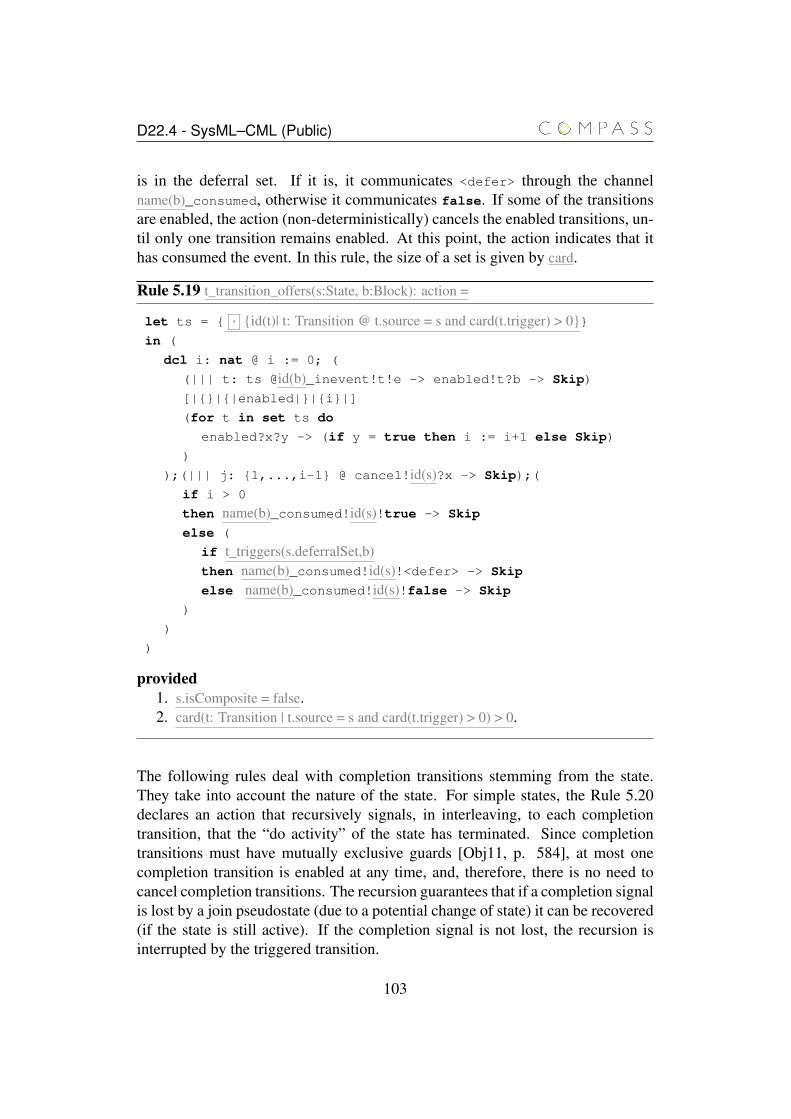
D22.4 - SysML–CML (Public)
is in the deferral set. If it is, it communicates <defer> through the channelname(b)_consumed, otherwise it communicates false. If some of the transitionsare enabled, the action (non-deterministically) cancels the enabled transitions, un-til only one transition remains enabled. At this point, the action indicates that ithas consumed the event. In this rule, the size of a set is given by card.
Rule 5.19 t_transition_offers(s:State, b:Block): action =
let ts = { , {id(t)| t: Transition @ t.source = s and card(t.trigger) > 0}}in (
dcl i: nat @ i := 0; (
(||| t: ts @id(b)_inevent!t!e -> enabled!t?b -> Skip)
[|{}|{|enabled|}|{i}|]
(for t in set ts do
enabled?x?y -> (if y = true then i := i+1 else Skip)
)
);(||| j: {1,...,i-1} @ cancel!id(s)?x -> Skip);(
if i > 0
then name(b)_consumed!id(s)!true -> Skip
else (
if t_triggers(s.deferralSet,b)then name(b)_consumed!id(s)!<defer> -> Skip
else name(b)_consumed!id(s)!false -> Skip
)
)
)
provided1. s.isComposite = false.2. card(t: Transition | t.source = s and card(t.trigger) > 0) > 0.
The following rules deal with completion transitions stemming from the state.They take into account the nature of the state. For simple states, the Rule 5.20declares an action that recursively signals, in interleaving, to each completiontransition, that the “do activity” of the state has terminated. Since completiontransitions must have mutually exclusive guards [Obj11, p. 584], at most onecompletion transition is enabled at any time, and, therefore, there is no need tocancel completion transitions. The recursion guarantees that if a completion signalis lost by a join pseudostate (due to a potential change of state) it can be recovered(if the state is still active). If the completion signal is not lost, the recursion isinterrupted by the triggered transition.
103
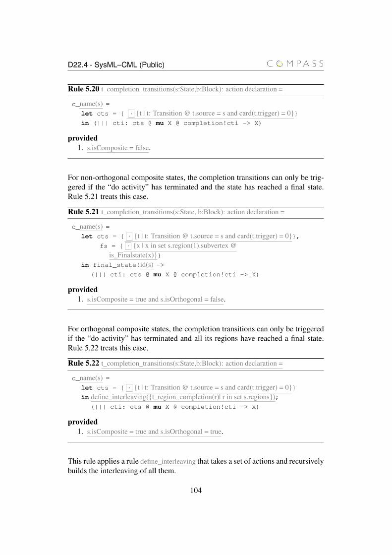
D22.4 - SysML–CML (Public)
Rule 5.20 t_completion_transitions(s:State,b:Block): action declaration =
c_name(s) =let cts = { , {t | t: Transition @ t.source = s and card(t.trigger) = 0}}in (||| cti: cts @ mu X @ completion!cti -> X)
provided1. s.isComposite = false.
For non-orthogonal composite states, the completion transitions can only be trig-gered if the “do activity” has terminated and the state has reached a final state.Rule 5.21 treats this case.
Rule 5.21 t_completion_transitions(s:State, b:Block): action declaration =
c_name(s) =let cts = { , {t | t: Transition @ t.source = s and card(t.trigger) = 0}},
fs = { , {x | x in set s.region(1).subvertex @is_Finalstate(x)}}
in final_state!id(s) ->(||| cti: cts @ mu X @ completion!cti -> X)
provided1. s.isComposite = true and s.isOrthogonal = false.
For orthogonal composite states, the completion transitions can only be triggeredif the “do activity” has terminated and all its regions have reached a final state.Rule 5.22 treats this case.
Rule 5.22 t_completion_transitions(s:State,b:Block): action declaration =
c_name(s) =let cts = { , {t | t: Transition @ t.source = s and card(t.trigger) = 0}}in define_interleaving({t_region_completion(r)| r in set s.regions});
(||| cti: cts @ mu X @ completion!cti -> X)
provided1. s.isComposite = true and s.isOrthogonal = true.
This rule applies a rule define_interleaving that takes a set of actions and recursivelybuilds the interleaving of all them.
104
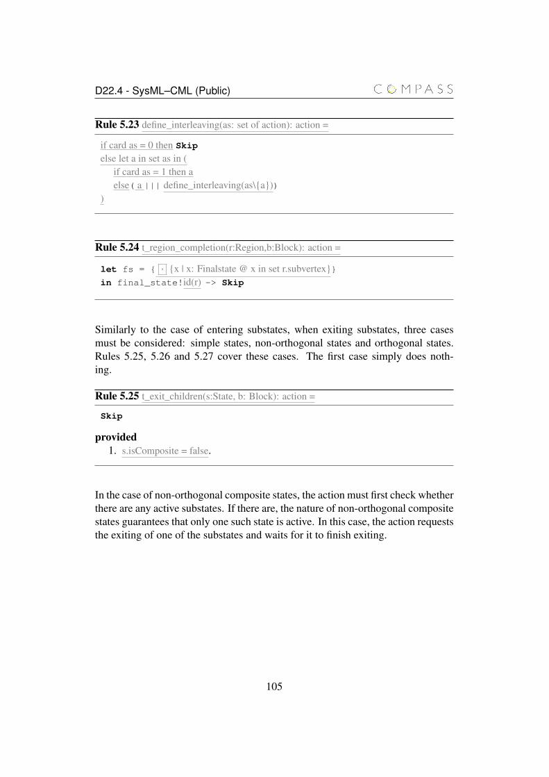
D22.4 - SysML–CML (Public)
Rule 5.23 define_interleaving(as: set of action): action =
if card as = 0 then Skip
else let a in set as in (if card as = 1 then aelse( a ||| define_interleaving(as\{a}))
)
Rule 5.24 t_region_completion(r:Region,b:Block): action =
let fs = { , {x | x: Finalstate @ x in set r.subvertex}}in final_state!id(r) -> Skip
Similarly to the case of entering substates, when exiting substates, three casesmust be considered: simple states, non-orthogonal states and orthogonal states.Rules 5.25, 5.26 and 5.27 cover these cases. The first case simply does noth-ing.
Rule 5.25 t_exit_children(s:State, b: Block): action =
Skip
provided1. s.isComposite = false.
In the case of non-orthogonal composite states, the action must first check whetherthere are any active substates. If there are, the nature of non-orthogonal compositestates guarantees that only one such state is active. In this case, the action requeststhe exiting of one of the substates and waits for it to finish exiting.
105
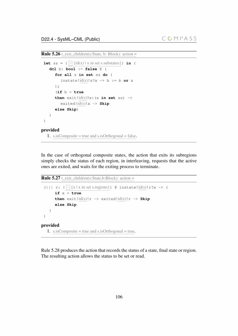
D22.4 - SysML–CML (Public)
Rule 5.26 t_exit_children(s:State, b: Block): action =
let ss = { , {id(x) | x in set s.substates}} in (
dcl b: bool := false @ (
for all s in set ss do (
instate!id(s)!s?x -> b := b or x
);
(if b = true
then exit!id(s)?x:(x in set ss) ->
exited!id(s)!x -> Skip
else Skip)
)
)
provided1. s.isComposite = true and s.isOrthogonal = false.
In the case of orthogonal composite states, the action that exits its subregionssimply checks the status of each region, in interleaving, requests that the activeones are exited, and waits for the exiting process to terminate.
Rule 5.27 t_exit_children(s:State,b:Block): action =
(||| r: { , {x | x in set s.regions}} @ instate!id(s)!r?x -> (
if x = true
then exit!id(s)!r -> exited!id(s)!r -> Skip
else Skip
)
)
provided1. s.isComposite = true and s.isOrthogonal = true.
Rule 5.28 produces the action that records the status of a state, final state or region.The resulting action allows the status to be set or read.
106
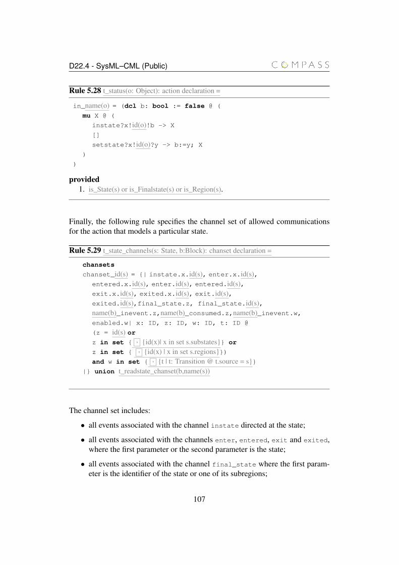
D22.4 - SysML–CML (Public)
Rule 5.28 t_status(o: Object): action declaration =
in_name(o) = (dcl b: bool := false @ (
mu X @ (
instate?x!id(o)!b -> X
[]
setstate?x!id(o)?y -> b:=y; X
)
)
provided1. is_State(s) or is_Finalstate(s) or is_Region(s).
Finally, the following rule specifies the channel set of allowed communicationsfor the action that models a particular state.
Rule 5.29 t_state_channels(s: State, b:Block): chanset declaration =
chansets
chanset_id(s) = {| instate.x.id(s), enter.x.id(s),entered.x.id(s), enter.id(s), entered.id(s),exit.x.id(s), exited.x.id(s), exit.id(s),exited.id(s),final_state.z, final_state.id(s),name(b)_inevent.z,name(b)_consumed.z,name(b)_inevent.w,enabled.w| x: ID, z: ID, w: ID, t: ID @
(z = id(s) orz in set { , {id(x)| x in set s.substates}} or
z in set { , {id(x) | x in set s.regions}})and w in set { , {t | t: Transition @ t.source = s}}
|} union t_readstate_chanset(b,name(s))
The channel set includes:
• all events associated with the channel instate directed at the state;
• all events associated with the channels enter, entered, exit and exited,where the first parameter or the second parameter is the state;
• all events associated with the channel final_state where the first param-eter is the identifier of the state or one of its subregions;
107
D22.4 - SysML–CML (Public)
• all events associated with the channels name(b)_inevent and name(b)_consumed,where the first parameter is the state, a substate or a subregion; and
• all events associated with the channel name(b)_inevent, where the first pa-rameter is a transition whose source is the state.
5.2.4 Regions
The translation rules for regions are similar to those for non-orthogonal compositestates (5.8, 5.14, 5.16 and 5.21). The rules apply as if the region belongs to a non-orthogonal composite state with no transitions, no entry or exit actions, and no“do activities”. This is a valid because regions are part of composite state, andcannot have behaviours or transitions (whose source is the region).
Regions are anonymous, therefore an appropriate unique name must be generated.The translation rules for the off and on actions associated with a region are givenbelow. Because regions of a composite state can be entered independently of theparent state (via interlevel transitions), it is necessary to check if the parent isactive before activating the regions, and, if not, request that it be activated. Sincemultiple regions can be entered at the same time (via fork pseudostate) and theactivation of the parent is not atomic (the request and the marking of the stateas active occur in separate communications), it is not enough to have the regionscheck the parent and request its activation, because two or more regions maycheck the status of the parent at the same time, observe it as inactive and requestits activation. The parent is only prepared to receive one activation request (wheninactive) and the model deadlocks if more request are raised.
To deal with this issue, we devise a simple protocol between a composite state andits orthogonal regions. The protocol enforces that only one of the regions checksand possibly requests the activation of the parent, and the remaining regions areresponsible for doing the same to each other in an order that allows the propaga-tion of the activation request from any region to the parent. This protocol relieson an ordering of the regions of the state, but this ordering does not affect theobservable execution of the regions. It is only necessary to enforce the protocol.This ordering is reflected in the translation rules by the parameter p that identifiesa sibling region that precedes r, or the state that contains r if the regions is the firstin the ordering of regions. Notice that any order is valid for the purposes of thisprotocol, as long as it is fixed, which is achieved by preprocessing the abstractsyntax, and converting the sets of regions into sequences of regions.
Regions are compartments of a composite state. They are similar to compositestates themselves, except that each region (and potentially one of its substates)
108
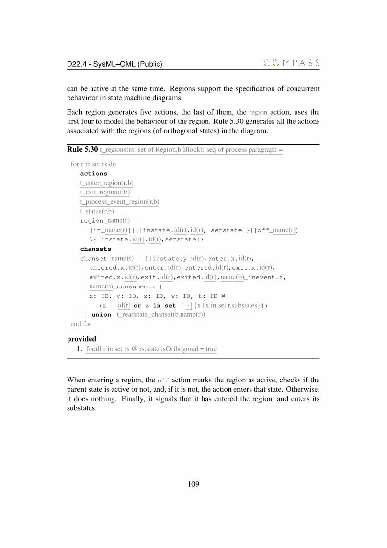
D22.4 - SysML–CML (Public)
can be active at the same time. Regions support the specification of concurrentbehaviour in state machine diagrams.
Each region generates five actions, the last of them, the region action, uses thefirst four to model the behaviour of the region. Rule 5.30 generates all the actionsassociated with the regions (of orthogonal states) in the diagram.
Rule 5.30 t_regions(rs: set of Region,b:Block): seq of process paragraph =
for r in set rs doactions
t_enter_region(r,b)t_exit_region(r,b)t_process_event_region(r,b)t_status(r,b)region_name(r) =
(in_name(r)[|{|instate.id(r).id(r), setstate|}|]off_name(r))\{|instate.id(r).id(r),setstate|}
chansets
chanset_name(r) = {|instate.y.id(r),enter.x.id(r),entered.x.id(r),enter.id(r),entered.id(r),exit.x.id(r),exited.x.id(r),exit.id(r),exited.id(r),name(b)_inevent.z,name(b)_consumed.z |
x: ID, y: ID, z: ID, w: ID, t: ID @
(z = id(r) or z in set { , {x | x in set r.substates}})|} union t_readstate_chanset(b,name(r))
end for
provided1. forall r in set rs @ rs.state.isOrthogonal = true
When entering a region, the off action marks the region as active, checks if theparent state is active or not, and, if it is not, the action enters that state. Otherwise,it does nothing. Finally, it signals that it has entered the region, and enters itssubstates.
109
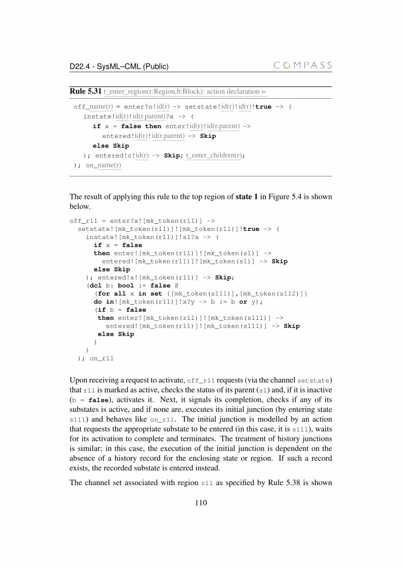
D22.4 - SysML–CML (Public)
Rule 5.31 t_enter_region(r:Region,b:Block): action declaration =
off_name(r) = enter?o!id(r) -> setstate!id(r)!id(r)!true -> (
instate!id(r)!id(r.parent)?x -> (
if x = false then enter!id(r)!id(r.parent) ->entered!id(r)!id(r.parent) -> Skip
else Skip
); entered!o!id(r) -> Skip; t_enter_children(r);); on_name(r)
The result of applying this rule to the top region of state 1 in Figure 5.4 is shownbelow.
off_r11 = enter?x![mk_token(r11)] ->setstate![mk_token(r11)]![mk_token(r11)]!true -> (
instate![mk_token(r11)]!s1?x -> (if x = falsethen enter![mk_token(r11)]![mk_token(s1)] ->
entered![mk_token(r11)]![mk_token(s1)] -> Skipelse Skip
); entered!x![mk_token(r11)] -> Skip;(dcl b: bool := false @(for all x in set {[mk_token(s111)],[mk_token(s112)]}do in![mk_token(r11)]!x?y -> b := b or y);(if b = falsethen enter![mk_token(r11)]![mk_token(s111)] ->
entered![mk_token(r11)]![mk_token(s111)] -> Skipelse Skip
))
); on_r11
Upon receiving a request to activate, off_r11 requests (via the channel setstate)that r11 is marked as active, checks the status of its parent (s1) and, if it is inactive(b = false), activates it. Next, it signals its completion, checks if any of itssubstates is active, and if none are, executes its initial junction (by entering states111) and behaves like on_r11. The initial junction is modelled by an actionthat requests the appropriate substate to be entered (in this case, it is s111), waitsfor its activation to complete and terminates. The treatment of history junctionsis similar; in this case, the execution of the initial junction is dependent on theabsence of a history record for the enclosing state or region. If such a recordexists, the recorded substate is entered instead.
The channel set associated with region r11 as specified by Rule 5.38 is shown
110
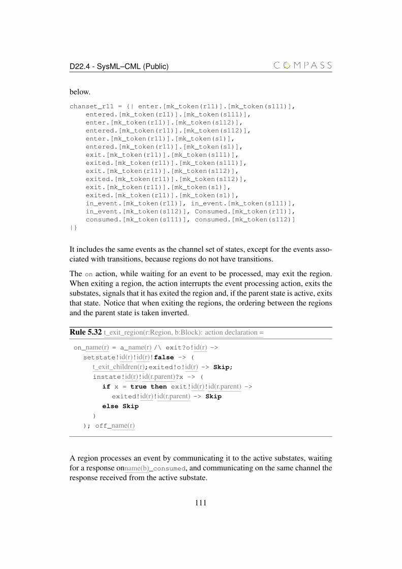
D22.4 - SysML–CML (Public)
below.
chanset_r11 = {| enter.[mk_token(r11)].[mk_token(s111)],entered.[mk_token(r11)].[mk_token(s111)],enter.[mk_token(r11)].[mk_token(s112)],entered.[mk_token(r11)].[mk_token(s112)],enter.[mk_token(r11)].[mk_token(s1)],entered.[mk_token(r11)].[mk_token(s1)],exit.[mk_token(r11)].[mk_token(s111)],exited.[mk_token(r11)].[mk_token(s111)],exit.[mk_token(r11)].[mk_token(s112)],exited.[mk_token(r11)].[mk_token(s112)],exit.[mk_token(r11)].[mk_token(s1)],exited.[mk_token(r11)].[mk_token(s1)],in_event.[mk_token(r11)], in_event.[mk_token(s111)],in_event.[mk_token(s112)], Consumed.[mk_token(r11)],consumed.[mk_token(s111)], consumed.[mk_token(s112)]
|}
It includes the same events as the channel set of states, except for the events asso-ciated with transitions, because regions do not have transitions.
The on action, while waiting for an event to be processed, may exit the region.When exiting a region, the action interrupts the event processing action, exits thesubstates, signals that it has exited the region and, if the parent state is active, exitsthat state. Notice that when exiting the regions, the ordering between the regionsand the parent state is taken inverted.
Rule 5.32 t_exit_region(r:Region, b:Block): action declaration =
on_name(r) = a_name(r) /\ exit?o!id(r) ->setstate!id(r)!id(r)!false -> (
t_exit_children(r);exited!o!id(r) -> Skip;
instate!id(r)!id(r.parent)?x -> (
if x = true then exit!id(r)!id(r.parent) ->exited!id(r)!id(r.parent) -> Skip
else Skip
)
); off_name(r)
A region processes an event by communicating it to the active substates, waitingfor a response onname(b)_consumed, and communicating on the same channel theresponse received from the active substate.
111
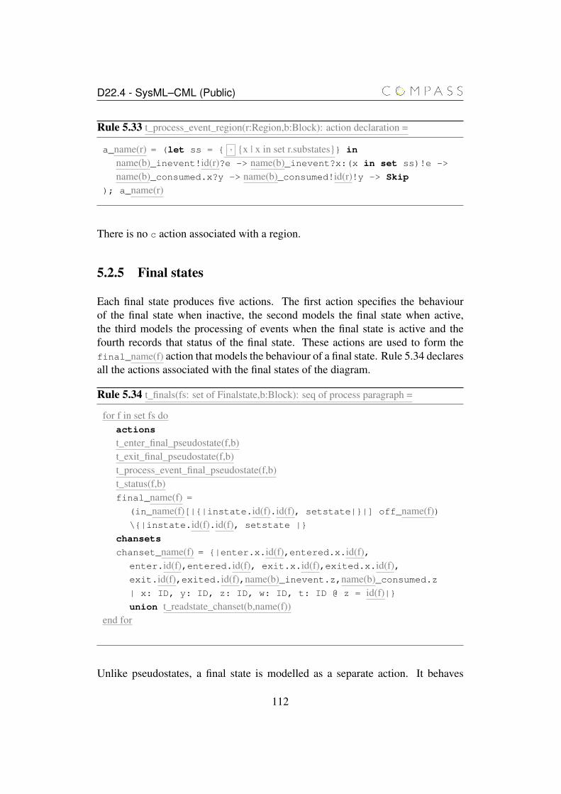
D22.4 - SysML–CML (Public)
Rule 5.33 t_process_event_region(r:Region,b:Block): action declaration =
a_name(r) = (let ss = { , {x | x in set r.substates}} in
name(b)_inevent!id(r)?e -> name(b)_inevent?x:(x in set ss)!e ->
name(b)_consumed.x?y -> name(b)_consumed!id(r)!y -> Skip
); a_name(r)
There is no c action associated with a region.
5.2.5 Final states
Each final state produces five actions. The first action specifies the behaviourof the final state when inactive, the second models the final state when active,the third models the processing of events when the final state is active and thefourth records that status of the final state. These actions are used to form thefinal_name(f) action that models the behaviour of a final state. Rule 5.34 declaresall the actions associated with the final states of the diagram.
Rule 5.34 t_finals(fs: set of Finalstate,b:Block): seq of process paragraph =
for f in set fs doactions
t_enter_final_pseudostate(f,b)t_exit_final_pseudostate(f,b)t_process_event_final_pseudostate(f,b)t_status(f,b)final_name(f) =
(in_name(f)[|{|instate.id(f).id(f), setstate|}|] off_name(f))\{|instate.id(f).id(f), setstate |}
chansets
chanset_name(f) = {|enter.x.id(f),entered.x.id(f),enter.id(f),entered.id(f), exit.x.id(f),exited.x.id(f),exit.id(f),exited.id(f),name(b)_inevent.z,name(b)_consumed.z| x: ID, y: ID, z: ID, w: ID, t: ID @ z = id(f)|}union t_readstate_chanset(b,name(f))
end for
Unlike pseudostates, a final state is modelled as a separate action. It behaves
112
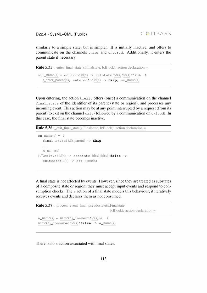
D22.4 - SysML–CML (Public)
similarly to a simple state, but is simpler. It is initially inactive, and offers tocommunicate on the channels enter and entered. Additionally, it enters theparent state if necessary.
Rule 5.35 t_enter_final_state(s:Finalstate, b:Block): action declaration =
off_name(s) = enter?o!id(s) -> setstate!id(s)!id(s)!true ->
t_enter_parent(s); entered!o!id(s) -> Skip; on_name(s)
Upon entering, the action t_exit offers (once) a communication on the channelfinal_state of the identifier of its parent (state or region), and processes anyincoming event. This action may be at any point interrupted by a request (from itsparent) to exit on the channel exit (followed by a communication on exited). Inthis case, the final state becomes inactive.
Rule 5.36 t_exit_final_state(s:Finalstate, b:Block): action declaration =
on_name(s) = (
final_state!id(s.parent) -> Skip
|||
a_name(s))/\exit?o!id(s) -> setstate!id(s)!id(s)!false ->
exited!o!id(s) -> off_name(s)
A final state is not affected by events. However, since they are treated as substatesof a composite state or region, they must accept input events and respond to con-sumption checks. The a action of a final state models this behaviour; it iterativelyreceives events and declares them as not consumed.
Rule 5.37 t_process_event_final_pseudostate(s:Finalstate,b:Block): action declaration =
a_name(s) = name(b)_inevent!id(s)?e ->
name(b)_consumed!id(s)!false -> a_name(s)
There is no c action associated with final states.
113
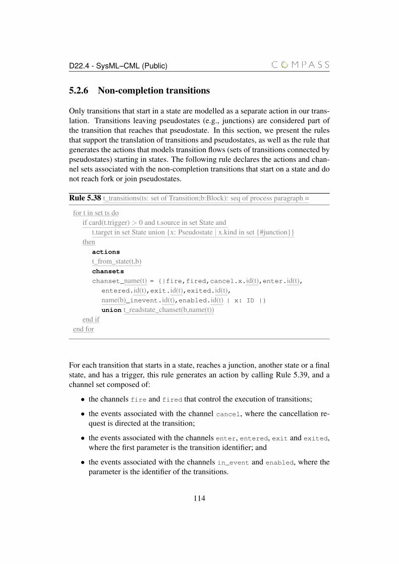
D22.4 - SysML–CML (Public)
5.2.6 Non-completion transitions
Only transitions that start in a state are modelled as a separate action in our trans-lation. Transitions leaving pseudostates (e.g., junctions) are considered part ofthe transition that reaches that pseudostate. In this section, we present the rulesthat support the translation of transitions and pseudostates, as well as the rule thatgenerates the actions that models transition flows (sets of transitions connected bypseudostates) starting in states. The following rule declares the actions and chan-nel sets associated with the non-completion transitions that start on a state and donot reach fork or join pseudostates.
Rule 5.38 t_transitions(ts: set of Transition;b:Block): seq of process paragraph =
for t in set ts doif card(t.trigger) > 0 and t.source in set State and
t.target in set State union {x: Pseudostate | x.kind in set {#junction}}then
actions
t_from_state(t,b)chansets
chanset_name(t) = {|fire,fired,cancel.x.id(t),enter.id(t),entered.id(t),exit.id(t),exited.id(t),name(b)_inevent.id(t),enabled.id(t) | x: ID |}
union t_readstate_chanset(b,name(t))end if
end for
For each transition that starts in a state, reaches a junction, another state or a finalstate, and has a trigger, this rule generates an action by calling Rule 5.39, and achannel set composed of:
• the channels fire and fired that control the execution of transitions;
• the events associated with the channel cancel, where the cancellation re-quest is directed at the transition;
• the events associated with the channels enter, entered, exit and exited,where the first parameter is the transition identifier; and
• the events associated with the channels in_event and enabled, where theparameter is the identifier of the transitions.
114
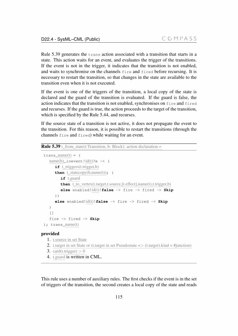
D22.4 - SysML–CML (Public)
Rule 5.39 generates the trans action associated with a transition that starts in astate. This action waits for an event, and evaluates the trigger of the transitions.If the event is not in the trigger, it indicates that the transition is not enabled,and waits to synchronise on the channels fire and fired before recursing. It isnecessary to restart the transition, so that changes in the state are available to thetransition even when it is not executed.
If the event is one of the triggers of the transition, a local copy of the state isdeclared and the guard of the transition is evaluated. If the guard is false, theaction indicates that the transition is not enabled, synchronises on fire and fired
and recurses. If the guard is true, the action proceeds to the target of the transition,which is specified by the Rule 5.44, and recurses.
If the source state of a transition is not active, it does not propagate the event tothe transition. For this reason, it is possible to restart the transitions (through thechannels fire and fired) while waiting for an event.
Rule 5.39 t_from_state(t:Transition, b: Block): action declaration =
trans_name(t) = (
name(b)_inevent!id(t)?e -> (
if t_triggers(t.trigger,b)then t_statecopy(b,name(t)); (
if t.guardthen t_to_vertex(t.target,t.source,[t.effect],name(t),t.trigger,b)else enabled!id(t)!false -> fire -> fired -> Skip
))
else enabled!id(t)!false -> fire -> fired -> Skip
)
[]
fire -> fired -> Skip
); trans_name(t)
provided1. t.source in set State2. t.target in set State or (t.target in set Pseudostate => (t.target).kind = #junction)3. card(t.trigger) > 04. t.guard is written in CML.
This rule uses a number of auxiliary rules. The first checks if the event is in the setof triggers of the transition, the second creates a local copy of the state and reads
115
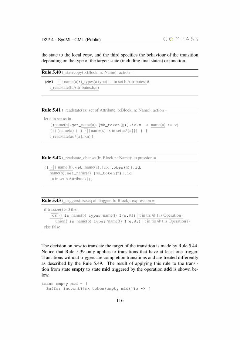
D22.4 - SysML–CML (Public)
the state to the local copy, and the third specifies the behaviour of the transitiondepending on the type of the target: state (including final states) or junction.
Rule 5.40 t_statecopy(b:Block, n: Name): action =
(dcl , {name(a):t_types(a.type) | a in set b.Attributes}@t_readstate(b.Attributes,b,n)
Rule 5.41 t_readstate(as: set of Attribute, b:Block, n: Name): action =
let a in set as in((name(b).get_name(a).[mk_token(n)].id?x -> name(a) := x)
[||{name(a) | { , {name(x) | x in set as\{a}}} ||]
t_readstate(as \{a},b,n) )
Rule 5.42 t_readstate_chanset(b: Block,n: Name): expression =
{| , { name(b).get_name(a).[mk_token(n)].id,name(b).set_name(a).[mk_token(n)].id| a in set b.Attributes}|}
Rule 5.43 t_triggers(trs:seq of Trigger, b: Block): expression =
if trs.size() > 0 thenor ({ is_name(b)_types‘name(t)_I(e.#3) | t in trs @ t is Operation}
union{ is_name(b)_types‘name(t)_I(e.#3) | t in trs @ t is Operation})else false
The decision on how to translate the target of the transition is made by Rule 5.44.Notice that Rule 5.39 only applies to transitions that have at least one trigger.Transitions without triggers are completion transitions and are treated differentlyas described by the Rule 5.49. The result of applying this rule to the transi-tion from state empty to state mid triggered by the operation add is shown be-low.
trans_empty_mid = (Buffer_inevent?[mk_token(empty_mid)]?e -> (
116
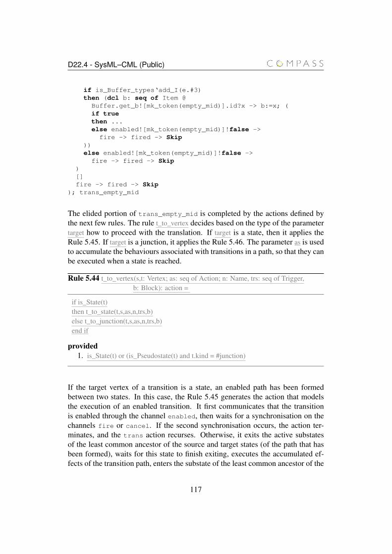
D22.4 - SysML–CML (Public)
if is_Buffer_types‘add_I(e.#3)then (dcl b: seq of Item @
Buffer.get_b![mk_token(empty_mid)].id?x -> b:=x; (if truethen ...else enabled![mk_token(empty_mid)]!false ->
fire -> fired -> Skip))else enabled![mk_token(empty_mid)]!false ->
fire -> fired -> Skip)[]fire -> fired -> Skip
); trans_empty_mid
The elided portion of trans_empty_mid is completed by the actions defined bythe next few rules. The rule t_to_vertex decides based on the type of the parametertarget how to proceed with the translation. If target is a state, then it applies theRule 5.45. If target is a junction, it applies the Rule 5.46. The parameter as is usedto accumulate the behaviours associated with transitions in a path, so that they canbe executed when a state is reached.
Rule 5.44 t_to_vertex(s,t: Vertex; as: seq of Action; n: Name, trs: seq of Trigger,b: Block): action =
if is_State(t)then t_to_state(t,s,as,n,trs,b)else t_to_junction(t,s,as,n,trs,b)end if
provided1. is_State(t) or (is_Pseudostate(t) and t.kind = #junction)
If the target vertex of a transition is a state, an enabled path has been formedbetween two states. In this case, the Rule 5.45 generates the action that modelsthe execution of an enabled transition. It first communicates that the transitionis enabled through the channel enabled, then waits for a synchronisation on thechannels fire or cancel. If the second synchronisation occurs, the action ter-minates, and the trans action recurses. Otherwise, it exits the active substatesof the least common ancestor of the source and target states (of the path that hasbeen formed), waits for this state to finish exiting, executes the accumulated ef-fects of the transition path, enters the substate of the least common ancestor of the
117
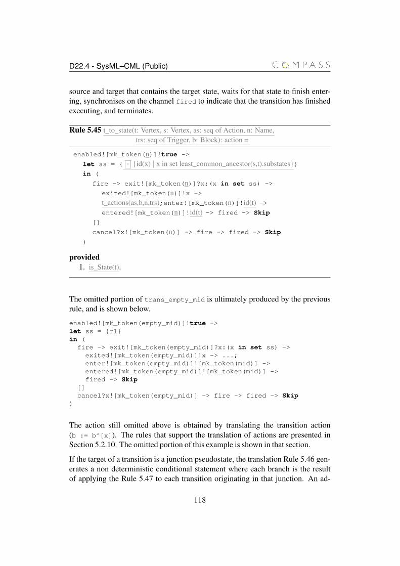
D22.4 - SysML–CML (Public)
source and target that contains the target state, waits for that state to finish enter-ing, synchronises on the channel fired to indicate that the transition has finishedexecuting, and terminates.
Rule 5.45 t_to_state(t: Vertex, s: Vertex, as: seq of Action, n: Name,trs: seq of Trigger, b: Block): action =
enabled![mk_token(n)]!true ->
let ss = { , {id(x) | x in set least_common_ancestor(s,t).substates}}in (
fire -> exit![mk_token(n)]?x:(x in set ss) ->
exited![mk_token(n)]!x ->
t_actions(as,b,n,trs);enter![mk_token(n)]!id(t) ->entered![mk_token(n)]!id(t) -> fired -> Skip
[]
cancel?x![mk_token(n)] -> fire -> fired -> Skip
)
provided1. is_State(t).
The omitted portion of trans_empty_mid is ultimately produced by the previousrule, and is shown below.
enabled![mk_token(empty_mid)]!true ->let ss = {r1}in (
fire -> exit![mk_token(empty_mid)]?x:(x in set ss) ->exited![mk_token(empty_mid)]!x -> ...;enter![mk_token(empty_mid)]![mk_token(mid)] ->entered![mk_token(empty_mid)]![mk_token(mid)] ->fired -> Skip
[]cancel?x![mk_token(empty_mid)] -> fire -> fired -> Skip
)
The action still omitted above is obtained by translating the transition action(b := b^[x]). The rules that support the translation of actions are presented inSection 5.2.10. The omitted portion of this example is shown in that section.
If the target of a transition is a junction pseudostate, the translation Rule 5.46 gen-erates a non deterministic conditional statement where each branch is the resultof applying the Rule 5.47 to each transition originating in that junction. An ad-
118
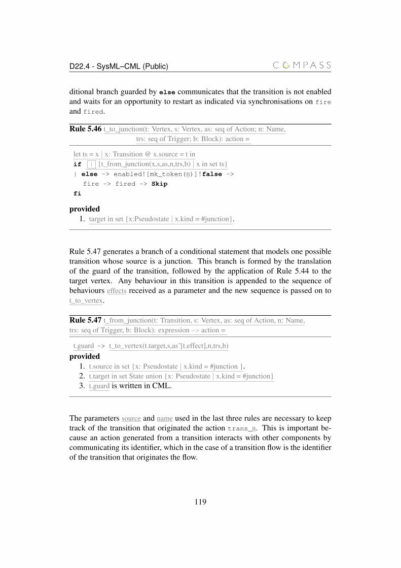
D22.4 - SysML–CML (Public)
ditional branch guarded by else communicates that the transition is not enabledand waits for an opportunity to restart as indicated via synchronisations on fire
and fired.
Rule 5.46 t_to_junction(t: Vertex, s: Vertex, as: seq of Action; n: Name,trs: seq of Trigger; b: Block): action =
let ts = x | x: Transition @ x.source = t inif | {t_from_junction(x,s,as,n,trs,b) | x in set ts}| else -> enabled![mk_token(n)]!false ->
fire -> fired -> Skip
fi
provided1. target in set {x:Pseudostate | x.kind = #junction}.
Rule 5.47 generates a branch of a conditional statement that models one possibletransition whose source is a junction. This branch is formed by the translationof the guard of the transition, followed by the application of Rule 5.44 to thetarget vertex. Any behaviour in this transition is appended to the sequence ofbehaviours effects received as a parameter and the new sequence is passed on tot_to_vertex.
Rule 5.47 t_from_junction(t: Transition, s: Vertex, as: seq of Action, n: Name,trs: seq of Trigger, b: Block): expression -> action =
t.guard -> t_to_vertex(t.target,s,asˆ[t.effect],n,trs,b)provided
1. t.source in set {x: Pseudostate | x.kind = #junction }.2. t.target in set State union {x: Pseudostate | x.kind = #junction}3. t.guard is written in CML.
The parameters source and name used in the last three rules are necessary to keeptrack of the transition that originated the action trans_n. This is important be-cause an action generated from a transition interacts with other components bycommunicating its identifier, which in the case of a transition flow is the identifierof the transition that originates the flow.
119
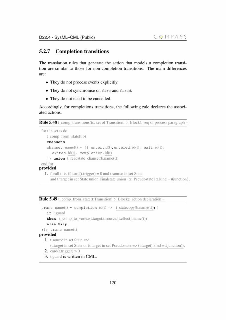
D22.4 - SysML–CML (Public)
5.2.7 Completion transitions
The translation rules that generate the action that models a completion transi-tion are similar to those for non-completion transitions. The main differencesare:
• They do not process events explicitly.
• They do not synchronise on fire and fired.
• They do not need to be cancelled.
Accordingly, for completions transitions, the following rule declares the associ-ated actions.
Rule 5.48 t_comp_transitions(ts: set of Transition; b: Block): seq of process paragraph =
for t in set ts dot_comp_from_state(t,b)chansets
chanset_name(t) = {| enter.id(t),entered.id(t), exit.id(t),exited.id(t), completion.id(t)
|} union t_readstate_chanset(b,name(t))end for
provided1. forall t: ts @ card(t.trigger) = 0 and t.source in set State
and t.target in set State union Finalstate union {x: Pseudostate | x.kind = #junction}.
Rule 5.49 t_comp_from_state(t:Transition; b: Block): action declaration =
trans_name(t) = completion!id(t) -> t_statecopy(b,name(t));(if t.guardthen t_comp_to_vertex(t.target,t.source,[t.effect],name(t))else Skip
)); trans_name(t)provided
1. t.source in set State and(t.target in set State or (t.target in set Pseudostate => (t.target).kind = #junction)).
2. card(t.trigger) > 03. t.guard is written in CML.
120
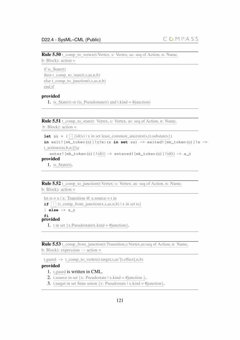
D22.4 - SysML–CML (Public)
Rule 5.50 t_comp_to_vertex(t:Vertex, s: Vertex, as: seq of Action, n: Name,b: Block): action =
if is_State(t)then t_comp_to_state(t,s,as,n,b)else t_comp_to_junction(t,s,as,n,b)end if
provided1. is_State(t) or (is_Pseudostate(t) and t.kind = #junction)
Rule 5.51 t_comp_to_state(t: Vertex, s: Vertex, as: seq of Action, n: Name,b: Block): action =
let ss = { , {id(x) | x in set least_common_ancestor(s,t).substates}}in exit![mk_token(n)]!n?x:(x in set ss) -> exited![mk_token(n)]!x ->
t_actions(as,b,n,[]);enter![mk_token(n)]!id(t) -> entered![mk_token(n)]!id(t) -> a_n
provided1. is_State(t).
Rule 5.52 t_comp_to_junction(t:Vertex; s: Vertex; as: seq of Action, n: Name,b: Block): action =
let ts = x | x: Transition @ x.source = t inif | {t_comp_from_junction(x,s,as,n,b) | x in set ts}| else -> a_nfi
provided1. t in set {x:Pseudostate|x.kind = #junction}.
Rule 5.53 t_comp_from_junction(t:Transition,s:Vertex,as:seq of Action, n: Name,b: Block): expression -> action =
t.guard -> t_comp_to_vertex(t.target,s,asˆ[t.effect],n,b)provided
1. t.guard is written in CML.2. t.source in set {x: Pseudostate | x.kind = #junction }.3. t.target in set State union {x: Pseudostate | x.kind = #junction}.
121
D22.4 - SysML–CML (Public)
5.2.8 Join and Fork pseudostates
As already explained, join and fork pseudostates are used to converge two or moretransitions from different regions of an orthogonal composite state, or, conversely,to fork a transition into two or more transitions that simultaneously reach differentregions of an orthogonal composite state.
A number of restrictions apply to this kind of pseudostates. In particular, a forkpseudostate must have exactly one transition reaching it, and at least two transi-tions leaving it. Similarly, join pseudostates must be reached by at least two tran-sitions, and have exactly one transition leaving them [Obj11, p. 558]. Transitionsleaving a fork pseudostate or reaching a join pseudostate must, respectively, reachor leave states contained in different regions of an orthogonal composite state[Obj11, p. 558]. Additionally, transitions reaching or leaving a join pseudostate,and transitions leaving a fork pseudostate cannot have triggers or guards [Obj11,p. 582].
We require that the transition reaching a fork pseudostate or leaving a join pseu-dostate must, respectively, originate or reach a state, not another pseudostate.
The action that models a join pseudostate waits for completion events from thesource states. This is possible because transitions reaching a join pseudostatecannot have triggers or guards. If non-completion transitions in the diagram areexecuted (via synchronisation on fire and fired) before all transitions receive acompletion event, the action stops waiting (interrupted) and recurses. It then exe-cutes (if possible) the outgoing transitions, exiting the relevant states and enteringthe target of the join.
The action that models a fork pseudostate is similar, but it can have guards andtriggers in the transition reaching it. It behaves similarly to a transition starting ina state, except that the actions in the outgoing transitions are executed in parallel,and the target states of the outgoing transitions are entered in parallel.
The first two rules declare the actions associated with join and fork pseudostates.
122
D22.4 - SysML–CML (Public)
Rule 5.54 t_joins(js: set of Pseudostate, b: Block): seq of process paragraph =
for j in set js dot_join(j)chansets
chanset_name(j) = {|fire,fired,enter.id(j), entered.id(j),exit.id(j), exited.id(j),completion.x| x: ID @ x in set { , {id(t)|t:Transition @ t.target = j}}
|} union t_readstate_chanset(b,name(j))end for
provided1. js subset {x: Pseudostate | x.kind = #join}
For each join pseudostate in the diagram, the action that models it is declared anda channel set is declared. This channel set contains the same events as the channelsets for completion transitions, except that the channels fire and fired are alsoincluded.
Rule 5.55 t_forks(fs: set of Pseudostate; b: Block): seq of process paragraph =
for f in set fs dolet t = iota t: Transition @ t.target = f in
t_fork(f)chansets
chanset_name(j) = {|fire,fired,enter.id(j), entered.id(j),exit.id(j), exited.id(j),name(b)_inevent.id(t), cancel.x.id(t),enabled.id(t)|x:ID|} union t_readstate_chanset(b,name(f))
end forprovided
1. fs subset {x: Pseudostate | x.kind = #fork}
Similarly for each fork pseudostate in the diagram, this rule takes the unique tran-sition that reaches the fork pseudostate using the iota operator, and declares theaction that models it and the associated channel set. Unlike the case of the joinpseudostate, the channel set for a fork pseudostate is the same as that of a non-completion transition.
The following rule generates the action that models a join pseudostate.
123

D22.4 - SysML–CML (Public)
Rule 5.56 t_join(j:Pseudostate, b: Block): action declaration =
let outt = iota t: Transition @ t.source = j intrans_name(j) = mu X @ (
let ts = { , {id(t)| t: Transition @ t.target = j}} in (
(
(||| t: ts @ completion!t -> Skip)/\
fire -> fired -> trans_name(j));
t_statecopy(b,name(t));(if outt.guardthen exit!id(outt)!id(src) -> exited!id(outt)!id(src) ->
( ||| {t_action(t.effect,b,name(outt),[]) | t in set Transition @t.target = j});
t_action(outt.effect,b,name(outt),[]);enter!id(outt)!id(outt.target) ->entered!id(outt)!id(outt.target) -> Skip
else fire -> fired -> Skip
))
)
); X
where1. src is the the orthogonal composite state that contains the regions from
which the transitions originate.provided
1. j in set {x: Pseudostate | x.kind = #join}
For a join pseudostate, the generated action synchronises on completion1, in in-terleaving, for each transition reaching the join pseudostate. At any moment thisinterleaving can be interrupted by a synchronisation on fire which restarts thejoin pseudostate. Next, the action checks if the guard of the outgoing transitionis true. If it is, the orthogonal composite state that originates the incoming transi-tions is exited, each transition action is executed in interleaving, the action of theoutgoing transition is executed and the target state is entered. If the guard is nottrue, the action waits for the next event fire (that indicates a potential change ofstate). Finally, the action recurses.
1constraint 2 on page 582 of [Obj10b] forbids triggers or guards in transitions reaching joinpseudostates. While constraint 5 on the same page further restricts the outgoing transition not tohave triggers, it does not forbid guards.
124

D22.4 - SysML–CML (Public)
The action generated by the next rule models a transition originating from a statereaching a fork pseudostate.
Rule 5.57 t_fork(f: Pseudostate; b: Block): action declaration =
let int = iota t: Transition @ t.target = f intrans_name(int) = mu X @ (
name(b)_inevent!id(int)?e -> Skip;
t_statecopy(b,name(int));(if t_triggers(t.trigger) and t.guardthen enabled!id(int)!true -> (
fire -> exit!id(int)!id(int.source) ->exited!id(int)!id(int.source) -> Skip;
t_action(t.effect,b,name(int),int.trigger);(||| {t_action(t.effect,b,name(int),[]);enter!id(int)!id(t.target) ->entered!id(int)!id(t.target) -> Skip)
| t in set Transition @ t.source = j}); fired -> Skip
[]
cancel?x!m![mk_token(name(int))] -> fire -> fired -> Skip
)
else enabled!id(int)!false -> fire -> fired -> Skip
))
[]
fire -> fired -> Skip
); Xprovided
1. f in set {x: Pseudostate | x.kind = #fork}
This action initially offers a choice of receiving an event, or synchronising onfire. In the latter case, it then synchronises on fired. In the former case, theaction reads the state components used in the guard, evaluates the trigger and theguard of the transitions that reaches the fork, and if they evaluate to true, sig-nals that the transition is enabled, waits for fire and executes the behavioursassociated with the transition. Next, in interleaving, it executes the behavioursassociated with the transitions leaving the fork pseudostate and enters their targetstates. Once the interleaving terminates, it synchronises on fired. If the trig-ger and guard evaluate to false, the action synchronises first in fire and then onfired. Finally, in all cases, the action recurses.
125
D22.4 - SysML–CML (Public)
5.2.9 Initial pseudostates
Initial pseudostates and the transitions that follow are not modelled as a separateaction in our approach. The action derived from these elements is part of theaction that models the state or region that contains the initial pseudostate as shownin Rule 5.12.
The UML standard [Obj11]is not consistent about the use of guards on transi-tions leaving initial pseudostates. For instance, the standard claims that “outgo-ing transitions from the initial vertex may have a behaviour, but not a trigger orguard” [Obj11, p. 551]. In a different section, it claims that “[t]ransitions outgo-ing pseudostates may not have a trigger (except for those coming out of the initialpseudostate)”[Obj11, p. 582]. In this translation, we assume that transitions leav-ing initial pseudostates do not have triggers or guards, and for all transition flowsstarting from an initial pseudostate, for all junctions in the flow, the conjunction ofguards of its transitions is true. This is necessary, otherwise an initial pseudostatemay not enter a state.
The rules are similar to those for transitions, except that:
• Initial pseudostates do not generate separate actions;
• Transitions in flows starting in initial pseudostates do not synchronise onthe channels fire, fired, enabled, cancel or name(b)_inevent.
• The triggers of transitions leaving a junction (in the flow) form a cover.
Rule 5.58 t_initial_pseudostate(s: State,b:Block): action =
let t = iota x: Transition @ x.source = s.initial int_initial_to_vertex(t.target,[t.effect],name(s),b)
provided1. s in set State => s.isComposite = true and s.isOrthogonal = false or s in set Region
Rule 5.59 t_init_to_vertex(t:Vertex,as:seq of Action,n: Name,b:Block): action =
if is_State(t)then t_init_to_state(t,as,n,b)else t_init_to_junction(t,as,n,b)end if
provided1. is_State(t) or (is_Pseudostate(t) and t.kind = #junction)
126
D22.4 - SysML–CML (Public)
Rule 5.60 t_init_to_state(t:Vertex, as: seq of Action; n: Name; b: Block): action =
t_actions(as,b,n,[]);enter![mk_token(n)]!id(t) ->entered![mk_token(n)]!id(t) -> Skip
provided1. is_State(t).
Rule 5.61 t_init_to_junction(t:Vertex,as: seq of Action, n: Name, b: Block): action =
let ts = set2seq(y | y: Transition @ y.source = t) int_statecopy(b,n);
if | {t_init_from_junction(x,as,n) | x in set ts}fi
)provided
1. target in set {x | x:Pseudostate @ x.kind = #junction}.
Rule 5.62 t_init_from_junction(t:Transition, as: seq of Action,n: Name): expression -> action =
t.guard -> t_init_to_vertex(t.target,asˆ[t.effect],n)provided
1. t.source in set {x: Pseudostate | x.kind = #junction }.2. t.target in set State union {x: Pseudostate | x.kind = #junction}
5.2.10 Actions
The following rule translates an action without taking into consideration the con-text in which it is executed. For composite CML statements (e.g., sequential com-position), the rule translates the subactions and combines them using the samecombinator. For operation calls without return values, the rule generates an actionthat constructs a record of the type associated with the operation with the parame-ters of the call and sends it to the instance of the block (id) from the element thatrequested it ([mk_token(n)]), next it waits for an answer on the same channel.For operation calls with a return value, the action is similar, except that after re-ceiving an answer, the component _ret of the record is assigned to the variablev.
127
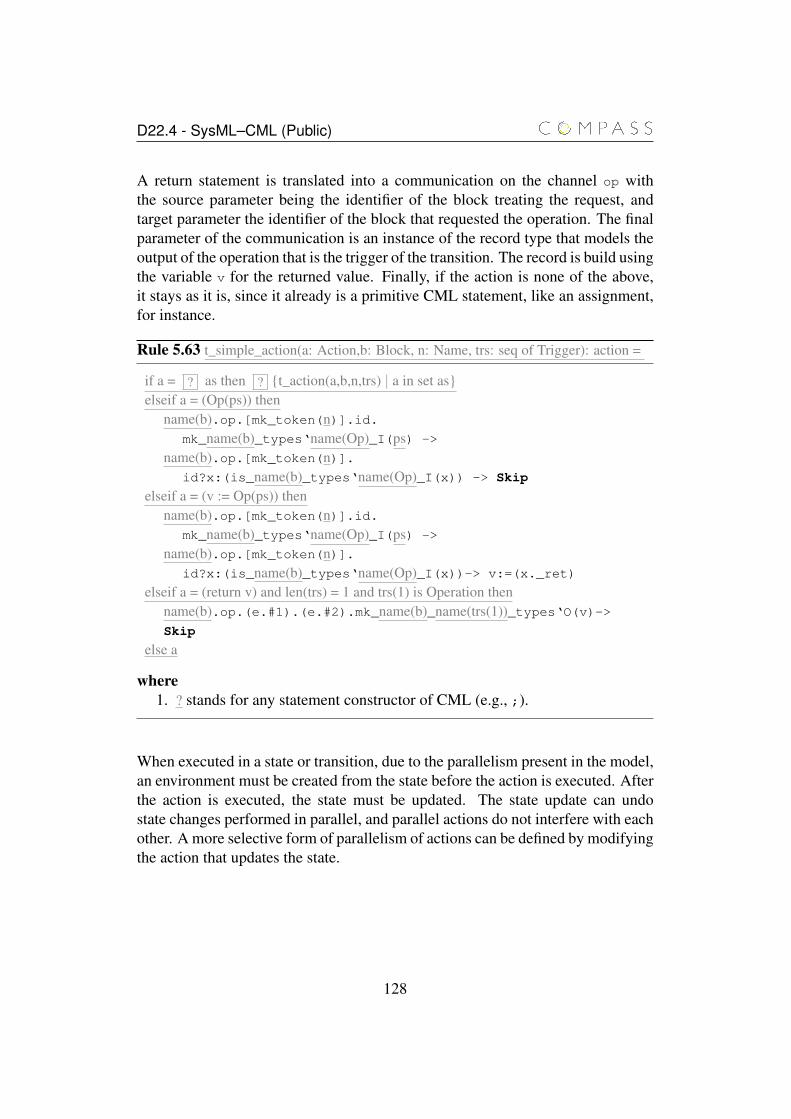
D22.4 - SysML–CML (Public)
A return statement is translated into a communication on the channel op withthe source parameter being the identifier of the block treating the request, andtarget parameter the identifier of the block that requested the operation. The finalparameter of the communication is an instance of the record type that models theoutput of the operation that is the trigger of the transition. The record is build usingthe variable v for the returned value. Finally, if the action is none of the above,it stays as it is, since it already is a primitive CML statement, like an assignment,for instance.
Rule 5.63 t_simple_action(a: Action,b: Block, n: Name, trs: seq of Trigger): action =
if a = ? as then ? {t_action(a,b,n,trs) | a in set as}elseif a = (Op(ps)) then
name(b).op.[mk_token(n)].id.mk_name(b)_types‘name(Op)_I(ps) ->
name(b).op.[mk_token(n)].id?x:(is_name(b)_types‘name(Op)_I(x)) -> Skip
elseif a = (v := Op(ps)) thenname(b).op.[mk_token(n)].id.
mk_name(b)_types‘name(Op)_I(ps) ->
name(b).op.[mk_token(n)].id?x:(is_name(b)_types‘name(Op)_I(x))-> v:=(x._ret)
elseif a = (return v) and len(trs) = 1 and trs(1) is Operation thenname(b).op.(e.#1).(e.#2).mk_name(b)_name(trs(1))_types‘O(v)->Skip
else a
where1. ? stands for any statement constructor of CML (e.g., ;).
When executed in a state or transition, due to the parallelism present in the model,an environment must be created from the state before the action is executed. Afterthe action is executed, the state must be updated. The state update can undostate changes performed in parallel, and parallel actions do not interfere with eachother. A more selective form of parallelism of actions can be defined by modifyingthe action that updates the state.
128
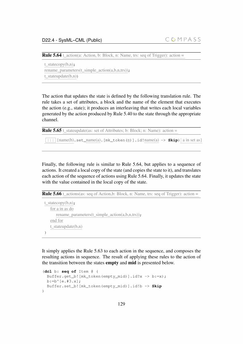
D22.4 - SysML–CML (Public)
Rule 5.64 t_action(a: Action, b: Block, n: Name, trs: seq of Trigger): action =
t_statecopy(b,n);rename_parameters(t_simple_action(a,b,n,trs));t_stateupdate(b,n))
The action that updates the state is defined by the following translation rule. Therule takes a set of attributes, a block and the name of the element that executesthe action (e.g., state); it produces an interleaving that writes each local variablesgenerated by the action produced by Rule 5.40 to the state through the appropriatechannel.
Rule 5.65 t_stateupdate(as: set of Attributes; b: Block; n: Name): action =
||| {name(b).set_name(a).[mk_token(n)].id!name(a) -> Skip)| a in set as}
Finally, the following rule is similar to Rule 5.64, but applies to a sequence ofactions. It created a local copy of the state (and copies the state to it), and translateseach action of the sequence of actions using Rule 5.64. Finally, it updates the statewith the value contained in the local copy of the state.
Rule 5.66 t_actions(as: seq of Action,b: Block, n: Name, trs: seq of Trigger): action =
t_statecopy(b,n);for a in as do
rename_parameters(t_simple_action(a,b,n,trs));end fort_stateupdate(b,n)
)
It simply applies the Rule 5.63 to each action in the sequence, and composes theresulting actions in sequence. The result of applying these rules to the action ofthe transition between the states empty and mid is presented below.
(dcl b: seq of Item @ (Buffer.get_b![mk_token(empty_mid)].id?x -> b:=x);b:=b^[e.#3.x];Buffer.set_b![mk_token(empty_mid)].id!b -> Skip
)
129
D22.4 - SysML–CML (Public)
In this action, a local copy of the state of the block Buffer is declared and thevalues stored in the block are copied to the local variables. Next, the assignmentis executed with the parameter variable x replaced by the component of the recordthat models the operation call and is stored in the third position of the tuple e (thisreplacement is achieved through the rule rename_parameters). Finally, the localstate is used to update the block’s state.
5.3 Related work
UML state machine diagrams have been extensively formalised. However, in mostcases, key features, such as join, fork and history pseudostates, interlevel transi-tions and completion events are not covered. Moreover, in most cases the formali-sation relies on certain restrictions to produce simpler models, making extensionsof the approach difficult, if not impossible, without comprehensive re-working ofthe formalisation. For instance, an assumption that there are no interlevel transi-tions yields a very simple model and translation rules, which cannot be directlyextended to account for interlevel transitions.
[Wha10] proposes a parametrised structural operational semantics that can be in-stantiated for UML state machine diagrams. A structural operational semanticsdescribes the result of executing a program (or chart) in terms of the executionof its parts. [LMM99] proposes a translation strategy between UML state ma-chine diagrams and extended hierarchical automata, which are automata extendedwith hierarchy (sequential and parallel composition) and information that allowsparticular substates to be entered. Additionally, [LMM99] defines an operationalsemantics for such automata. Similarly, [LP99] translates UML state machinediagrams into PROMELA, the input language for the model checker SPIN, tosupport the analysis of the diagrams. All these works focus on verification ofproperties of UML state machine diagrams in isolation. Moreover, none of theseapproaches directly support refinement, thus, support to this technique requiresthe development of new theories and techniques.
[NB03] translates UML state machine diagrams to CSP processes by associatingstates to CSP processes, and UML events to CSP events. The execution of multi-ple transitions is modelled by external and internal choice depending on the natureof the transitions (explicitly or implicitly triggered). Due to the limited subset ofstate machine diagrams that is covered in this work, the benefits of reusing theseresults would be small when compared with the effort necessary to extend the ap-proach and integrate in a semantics of SysML that takes different diagrams intoaccount.
130
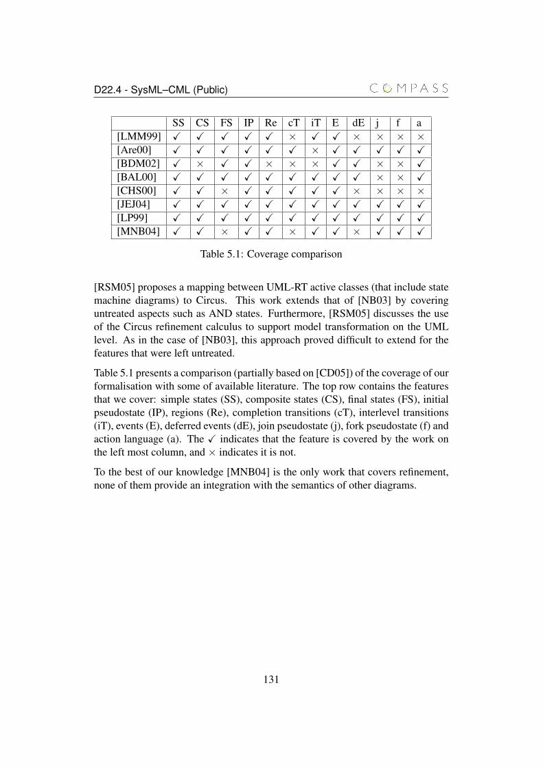
D22.4 - SysML–CML (Public)
SS CS FS IP Re cT iT E dE j f a[LMM99] X X X X X × X X × × × ×[Are00] X X X X X X × X X X X X[BDM02] X × X X × × × X X × × X[BAL00] X X X X X X X X X × × X[CHS00] X X × X X X X X × × × ×[JEJ04] X X X X X X X X X X X X[LP99] X X X X X X X X X X X X[MNB04] X X × X X × X X × X X X
Table 5.1: Coverage comparison
[RSM05] proposes a mapping between UML-RT active classes (that include statemachine diagrams) to Circus. This work extends that of [NB03] by coveringuntreated aspects such as AND states. Furthermore, [RSM05] discusses the useof the Circus refinement calculus to support model transformation on the UMLlevel. As in the case of [NB03], this approach proved difficult to extend for thefeatures that were left untreated.
Table 5.1 presents a comparison (partially based on [CD05]) of the coverage of ourformalisation with some of available literature. The top row contains the featuresthat we cover: simple states (SS), composite states (CS), final states (FS), initialpseudostate (IP), regions (Re), completion transitions (cT), interlevel transitions(iT), events (E), deferred events (dE), join pseudostate (j), fork pseudostate (f) andaction language (a). The X indicates that the feature is covered by the work onthe left most column, and × indicates it is not.
To the best of our knowledge [MNB04] is the only work that covers refinement,none of them provide an integration with the semantics of other diagrams.
131
Chapter 6
Sequence diagrams
The translation rules that cater for the link between SysML sequence diagram andCML are presented and illustrated with the help of an example. Such translationis divided in the basic features of SDs and more complex constructs presentedfurther. To illustrate the basic features we use the same example of the Producer-Consumer where one possible scenario is depicted in a Sequence Diagram usingonly its basic elements.
This chapter is organised as follows. Section 6.1 describes the example we use toillustrate our translation rules, which are introduced in Section 6.2. Related workis presented in Section 6.3.
6.1 Examples
The example below depicts a scenario having three entities and their respectivelifelines: one producer, one buffer and one consumer. The behaviour illustratedis a very simple possibility of execution where the producer adds one item to thebuffer, then the consumer removes such item from the buffer. The add opera-tion is done asynchronously whilst the remove operation is synchronous and therespective reply message consists of the element retrieved. This can be seen inFigure 6.1.
Another way of represent this scenario is using InteractionUse. This is illustratedby figures 6.2 and 6.3. They show the same behaviour of the previous sequencediagram, however, we define a specific diagram to illustrate the removal of a item.This diagram is used inside the other as an InteractionUse. The first diagramdisplayed in Figure 6.2 shows an asynchronous message arriving from outside to
132
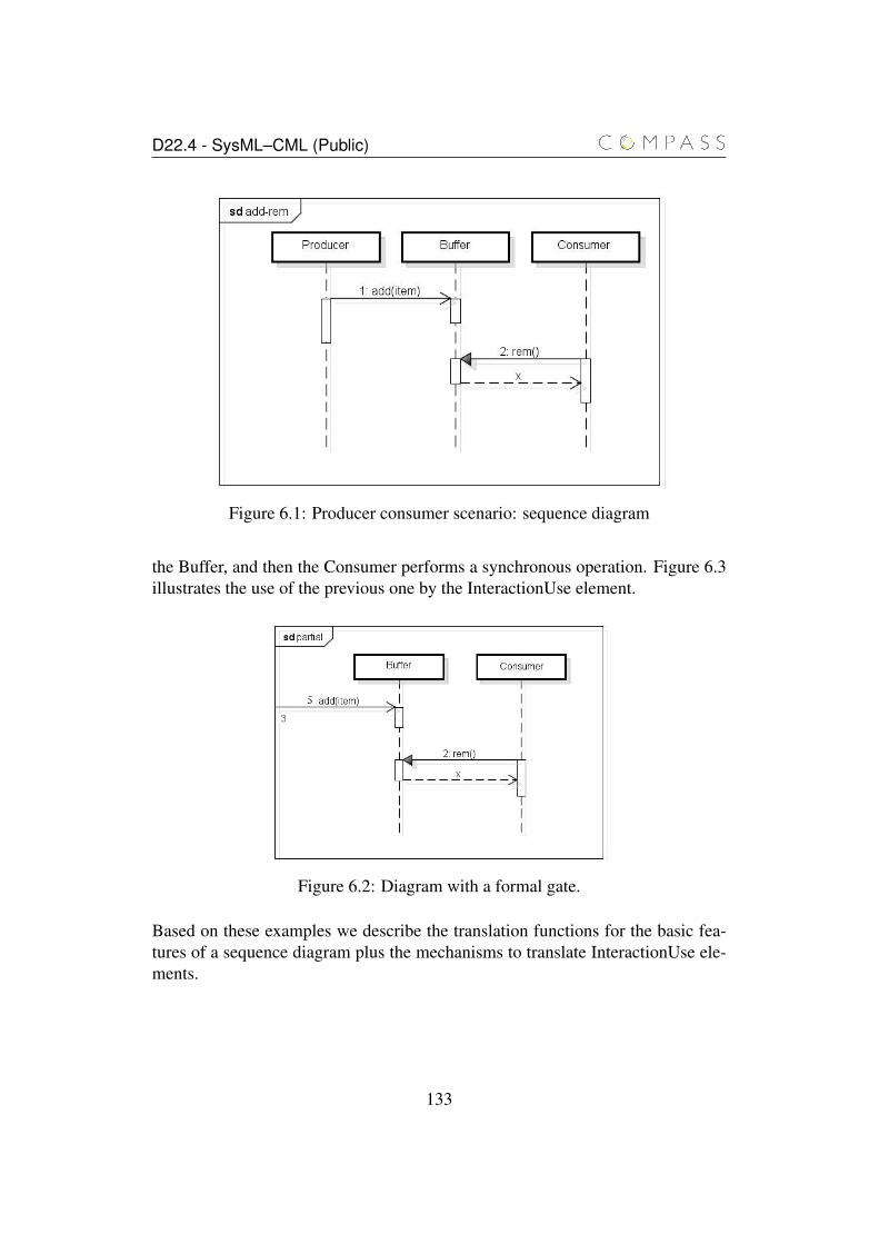
D22.4 - SysML–CML (Public)
Figure 6.1: Producer consumer scenario: sequence diagram
the Buffer, and then the Consumer performs a synchronous operation. Figure 6.3illustrates the use of the previous one by the InteractionUse element.
Figure 6.2: Diagram with a formal gate.
Based on these examples we describe the translation functions for the basic fea-tures of a sequence diagram plus the mechanisms to translate InteractionUse ele-ments.
133
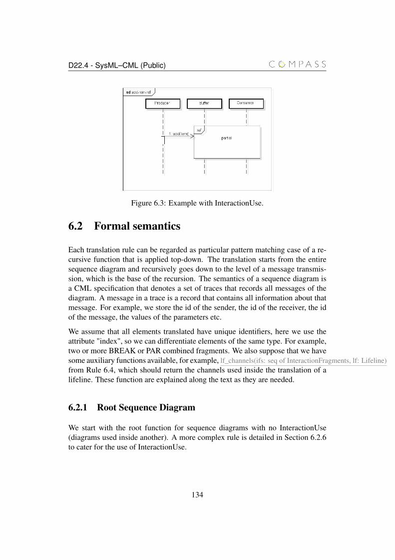
D22.4 - SysML–CML (Public)
Figure 6.3: Example with InteractionUse.
6.2 Formal semantics
Each translation rule can be regarded as particular pattern matching case of a re-cursive function that is applied top-down. The translation starts from the entiresequence diagram and recursively goes down to the level of a message transmis-sion, which is the base of the recursion. The semantics of a sequence diagram isa CML specification that denotes a set of traces that records all messages of thediagram. A message in a trace is a record that contains all information about thatmessage. For example, we store the id of the sender, the id of the receiver, the idof the message, the values of the parameters etc.
We assume that all elements translated have unique identifiers, here we use theattribute "index", so we can differentiate elements of the same type. For example,two or more BREAK or PAR combined fragments. We also suppose that we havesome auxiliary functions available, for example, lf_channels(ifs: seq of InteractionFragments, lf: Lifeline)from Rule 6.4, which should return the channels used inside the translation of alifeline. These function are explained along the text as they are needed.
6.2.1 Root Sequence Diagram
We start with the root function for sequence diagrams with no InteractionUse(diagrams used inside another). A more complex rule is detailed in Section 6.2.6to cater for the use of InteractionUse.
134
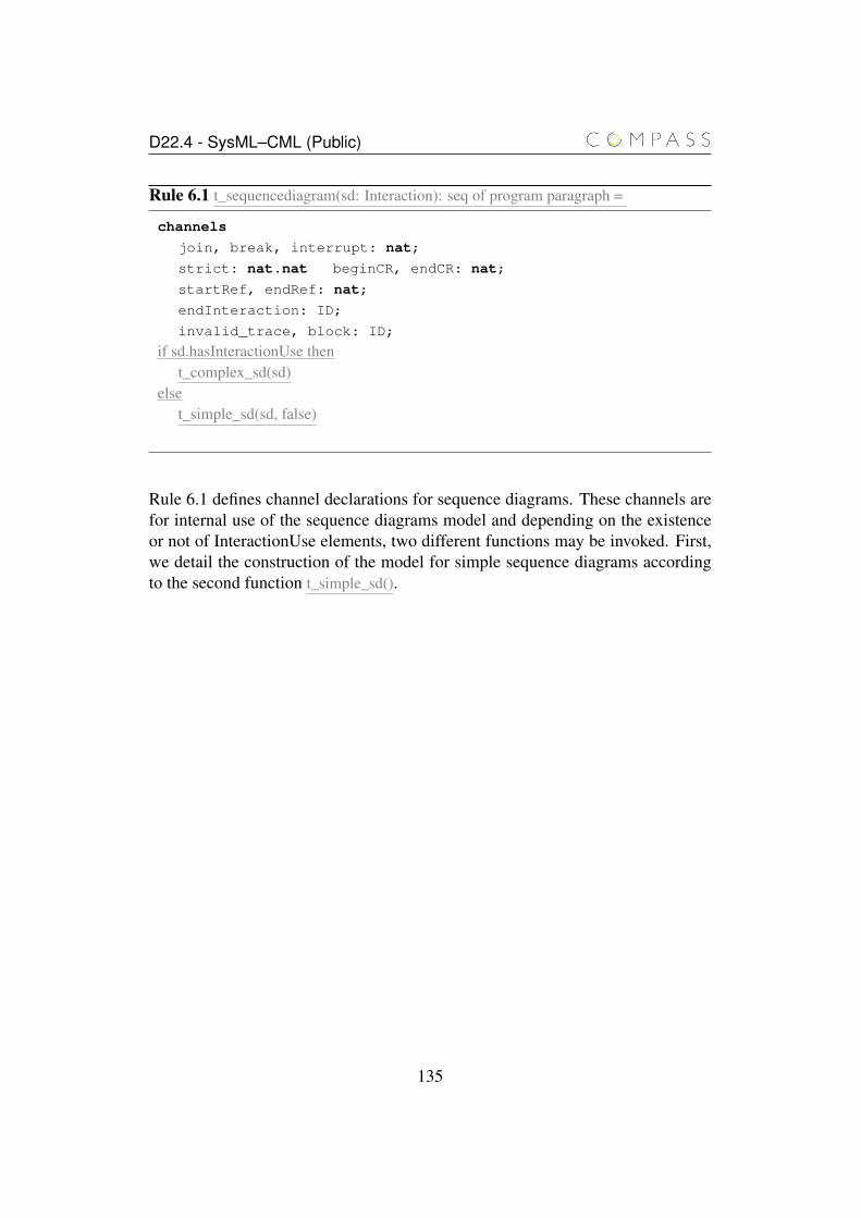
D22.4 - SysML–CML (Public)
Rule 6.1 t_sequencediagram(sd: Interaction): seq of program paragraph =
channels
join, break, interrupt: nat;
strict: nat.nat beginCR, endCR: nat;
startRef, endRef: nat;
endInteraction: ID;
invalid_trace, block: ID;
if sd.hasInteractionUse thent_complex_sd(sd)
elset_simple_sd(sd, false)
Rule 6.1 defines channel declarations for sequence diagrams. These channels arefor internal use of the sequence diagrams model and depending on the existenceor not of InteractionUse elements, two different functions may be invoked. First,we detail the construction of the model for simple sequence diagrams accordingto the second function t_simple_sd().
135

D22.4 - SysML–CML (Public)
Rule 6.2 t_simple_sd(sd: Interaction, internal: Boolean): seq of program paragraph =
if internal thenprocess sd_internal_name(sd) = sd_id: ID;
elseprocess sd_name(sd) = sd_id: ID;
end iffor lf in seq sd.Lifelines do
t_lifeline_name(lf)_id: ID;
end forfor gate in seq sd.formalGates do
name(gate)_id: ID;
end forlet paramList = {} in for m in seq sd.Messages do
for p in seq m.Arguments doif p.isInteractionParameter() and not exists(p.name, paramList) then
p.name: t_types(p.type) ;paramList = paramList union p.name end if
end forend for
@ begin
t_sd_chansets(sd)t_sd_actions(sd)end
Rule 6.2 defines the process for the diagram with a list of parameters, which rep-resent the ID for the sequence diagram, IDs for the lifelines, IDs for gates, ar-guments used in the messages that are defined as parameters of the Interaction,respectively. For the latter, we use a let expression to define a set paramList thatkeeps the parameters already defined and avoid duplicated parameter definitions.We check if the parameter has not been created yet through the use of functionexists(), which receives a element and a set and it checks if the element existsin the given set. The second argument of the translation function determinesif the CML process to be created is for an internal sequence diagram, which isused when defining diagrams with InteractionUse elements (more details in Sec-tion 6.2.6), or a usual one. Such verification only alters the name of the CMLprocess that is being created. Finally, we have the channel sets and actions dec-larations that will be explained further by Rules 6.4 and 6.5. The lifelines nameis acquired using an auxiliary function (t_lifeline_name(lf)) that will be explained
136
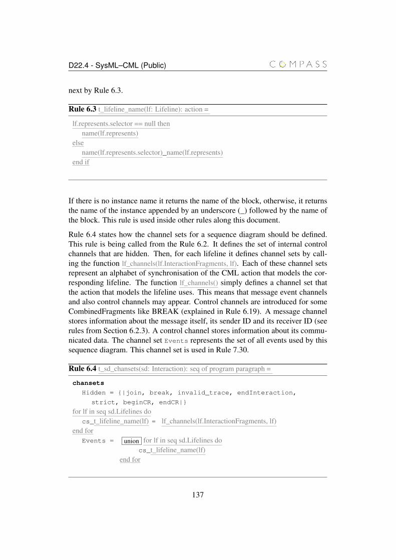
D22.4 - SysML–CML (Public)
next by Rule 6.3.
Rule 6.3 t_lifeline_name(lf: Lifeline): action =
lf.represents.selector == null thenname(lf.represents)
elsename(lf.represents.selector)_name(lf.represents)
end if
If there is no instance name it returns the name of the block, otherwise, it returnsthe name of the instance appended by an underscore (_) followed by the name ofthe block. This rule is used inside other rules along this document.
Rule 6.4 states how the channel sets for a sequence diagram should be defined.This rule is being called from the Rule 6.2. It defines the set of internal controlchannels that are hidden. Then, for each lifeline it defines channel sets by call-ing the function lf_channels(lf.InteractionFragments, lf). Each of these channel setsrepresent an alphabet of synchronisation of the CML action that models the cor-responding lifeline. The function lf_channels() simply defines a channel set thatthe action that models the lifeline uses. This means that message event channelsand also control channels may appear. Control channels are introduced for someCombinedFragments like BREAK (explained in Rule 6.19). A message channelstores information about the message itself, its sender ID and its receiver ID (seerules from Section 6.2.3). A control channel stores information about its commu-nicated data. The channel set Events represents the set of all events used by thissequence diagram. This channel set is used in Rule 7.30.
Rule 6.4 t_sd_chansets(sd: Interaction): seq of program paragraph =
chansets
Hidden = {|join, break, invalid_trace, endInteraction,
strict, beginCR, endCR|}
for lf in seq sd.Lifelines docs_t_lifeline_name(lf) = lf_channels(lf.InteractionFragments, lf)
end forEvents = union for lf in seq sd.Lifelines do
cs_t_lifeline_name(lf)end for
137
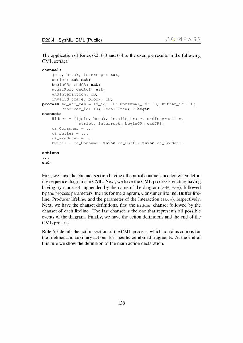
D22.4 - SysML–CML (Public)
The application of Rules 6.2, 6.3 and 6.4 to the example results in the followingCML extract:
channelsjoin, break, interrupt: nat;strict: nat.nat;beginCR, endCR: nat;startRef, endRef: nat;endInteraction: ID;invalid_trace, block: ID;
process sd_add_rem = sd_id: ID; Consumer_id: ID; Buffer_id: ID;Producer_id: ID; item: Item; @ begin
chansetsHidden = {|join, break, invalid_trace, endInteraction,
strict, interrupt, beginCR, endCR|}cs_Consumer = ...cs_Buffer = ...cs_Producer = ...Events = cs_Consumer union cs_Buffer union cs_Producer
actions...end
First, we have the channel section having all control channels needed when defin-ing sequence diagrams in CML. Next, we have the CML process signature havinghaving by name sd_ appended by the name of the diagram (add_rem), followedby the process parameters, the ids for the diagram, Consumer lifeline, Buffer life-line, Producer lifeline, and the parameter of the Interaction (item), respectively.Next, we have the chanset definitions, first the Hidden chanset followed by thechanset of each lifeline. The last chanset is the one that represents all possibleevents of the diagram. Finally, we have the action definitions and the end of theCML process.
Rule 6.5 details the action section of the CML process, which contains actions forthe lifelines and auxiliary actions for specific combined fragments. At the end ofthis rule we show the definition of the main action declaration.
138

D22.4 - SysML–CML (Public)
Rule 6.5 t_sd_actions(sd: Interaction): seq of program paragraph =
actions
for lf in seq sd.Lifelines dolf_t_lifeline_name(lf) = t_lf_interaction_fragments(lf.InteractionFragments, lf)if lf.hasLoopFragments() then
t_loop_actions(lf.getLoopCombinedFragments, lf)end if
end for
if sd.hasCriticalFragments() thent_critical_actions(sd.getCriticalCombinedFragments, sd)
end if
if sd.hasBreakCombinedFragment() thenBREAK = break?i -> interrupt!i -> BREAK
[] endInteraction.sd_id -> Skip
end if
t_main_action(sd)
We translate each lifeline to CML by calling t_lf_interaction_fragments(). Then,the conditional statement checks if there are any LOOP fragments inside the life-line in order to create auxiliary actions needed as a point of recursion for loops(Rule 6.17). The second conditional statement adds auxiliary actions for the treat-ment of the CRITICAL CombinedFragement in case there is one or more of them(Rule 6.20). The third conditional statement adds an auxiliary action in caseany BREAK CombinedFragment exists in order to halt the flow of a lifeline. ABREAK has a similar behaviour to an exception mechanism. If the BREAK con-dition is true, then some actions are executed followed by the interruption of theflow of the lifeline. The auxiliary action for the BREAK shown in Rule 6.5 catchesa BREAK interruption. A more detailed explanation on CombinedFragments isgiven in Section 6.2.4.
The result of the application of Rule 6.5 to our example should give the followingCML extract:
actionslf_Producer = ...
139
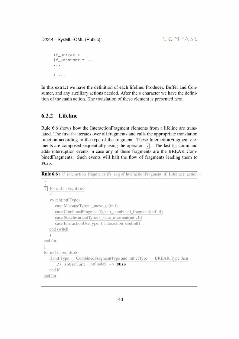
D22.4 - SysML–CML (Public)
lf_Buffer = ...lf_Consumer = ......
@ ...
In this extract we have the definition of each lifeline, Producer, Buffer and Con-sumer, and any auxiliary actions needed. After the @ character we have the defini-tion of the main action. The translation of these element is presented next.
6.2.2 Lifeline
Rule 6.6 shows how the InteractionFragment elements from a lifeline are trans-lated. The first for iterates over all fragments and calls the appropriate translationfunction according to the type of the fragment. These InteractionFragment ele-ments are composed sequentially using the operator ; . The last for commandadds interruption events in case any of these fragments are the BREAK Com-binedFragments. Such events will halt the flow of fragments leading them toSkip.
Rule 6.6 t_lf_interaction_fragments(ifs: seq of InteractionFragment, lf: Lifeline): action =
(
; for intf in seq ifs do(
switch(intf.Type)case MessageType: t_message(intf)case CombinedFragmentType: t_combined_fragment(intf, lf)case StateInvariantType: t_state_invariant(intf, lf)case InteractionUseType: t_interaction_use(intf)
end switch)
end for)
for intf in seq ifs doif intf.Type == CombinedFragmentType and intf.cfType == BREAK.Type then
/\ interrupt. intf.index -> Skip
end ifend for
140
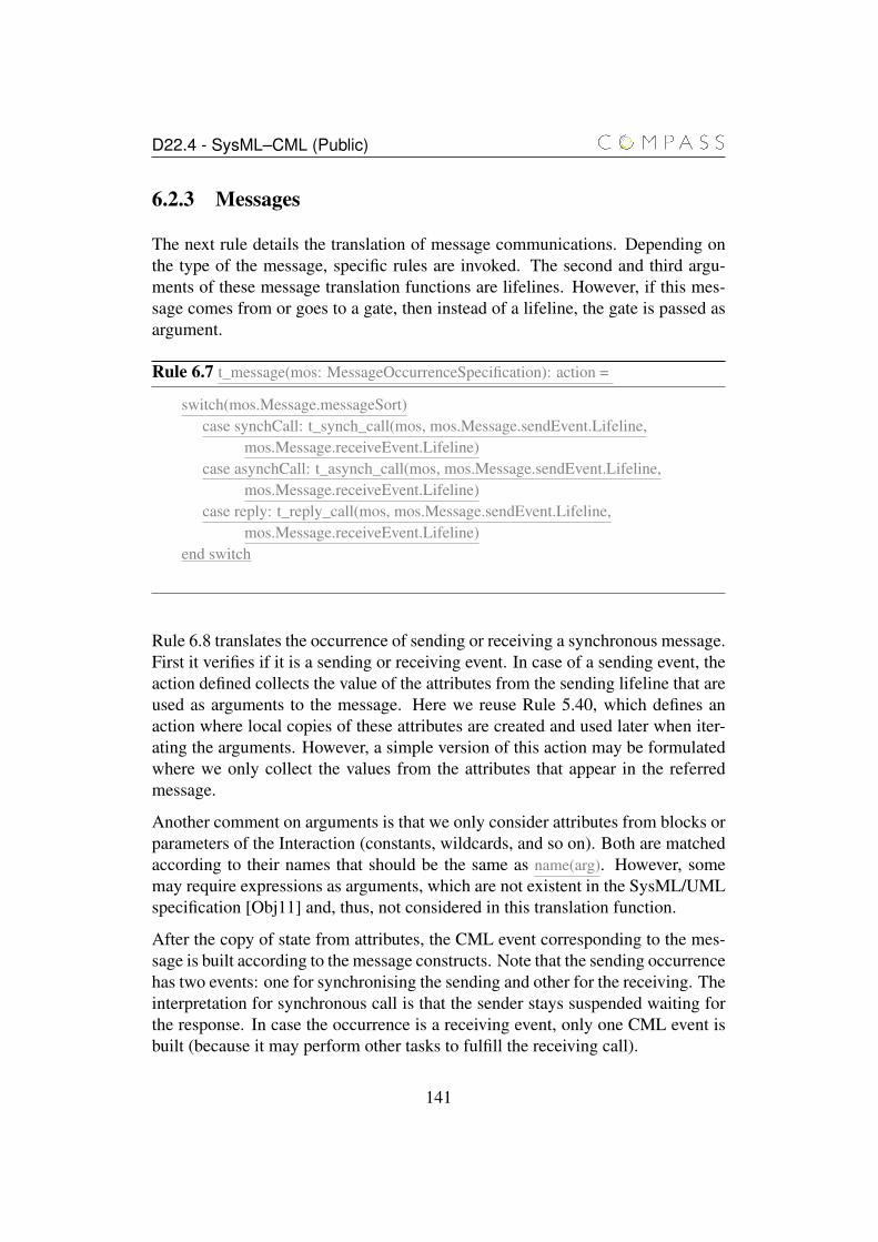
D22.4 - SysML–CML (Public)
6.2.3 Messages
The next rule details the translation of message communications. Depending onthe type of the message, specific rules are invoked. The second and third argu-ments of these message translation functions are lifelines. However, if this mes-sage comes from or goes to a gate, then instead of a lifeline, the gate is passed asargument.
Rule 6.7 t_message(mos: MessageOccurrenceSpecification): action =
switch(mos.Message.messageSort)case synchCall: t_synch_call(mos, mos.Message.sendEvent.Lifeline,
mos.Message.receiveEvent.Lifeline)case asynchCall: t_asynch_call(mos, mos.Message.sendEvent.Lifeline,
mos.Message.receiveEvent.Lifeline)case reply: t_reply_call(mos, mos.Message.sendEvent.Lifeline,
mos.Message.receiveEvent.Lifeline)end switch
Rule 6.8 translates the occurrence of sending or receiving a synchronous message.First it verifies if it is a sending or receiving event. In case of a sending event, theaction defined collects the value of the attributes from the sending lifeline that areused as arguments to the message. Here we reuse Rule 5.40, which defines anaction where local copies of these attributes are created and used later when iter-ating the arguments. However, a simple version of this action may be formulatedwhere we only collect the values from the attributes that appear in the referredmessage.
Another comment on arguments is that we only consider attributes from blocks orparameters of the Interaction (constants, wildcards, and so on). Both are matchedaccording to their names that should be the same as name(arg). However, somemay require expressions as arguments, which are not existent in the SysML/UMLspecification [Obj11] and, thus, not considered in this translation function.
After the copy of state from attributes, the CML event corresponding to the mes-sage is built according to the message constructs. Note that the sending occurrencehas two events: one for synchronising the sending and other for the receiving. Theinterpretation for synchronous call is that the sender stays suspended waiting forthe response. In case the occurrence is a receiving event, only one CML event isbuilt (because it may perform other tasks to fulfill the receiving call).
141
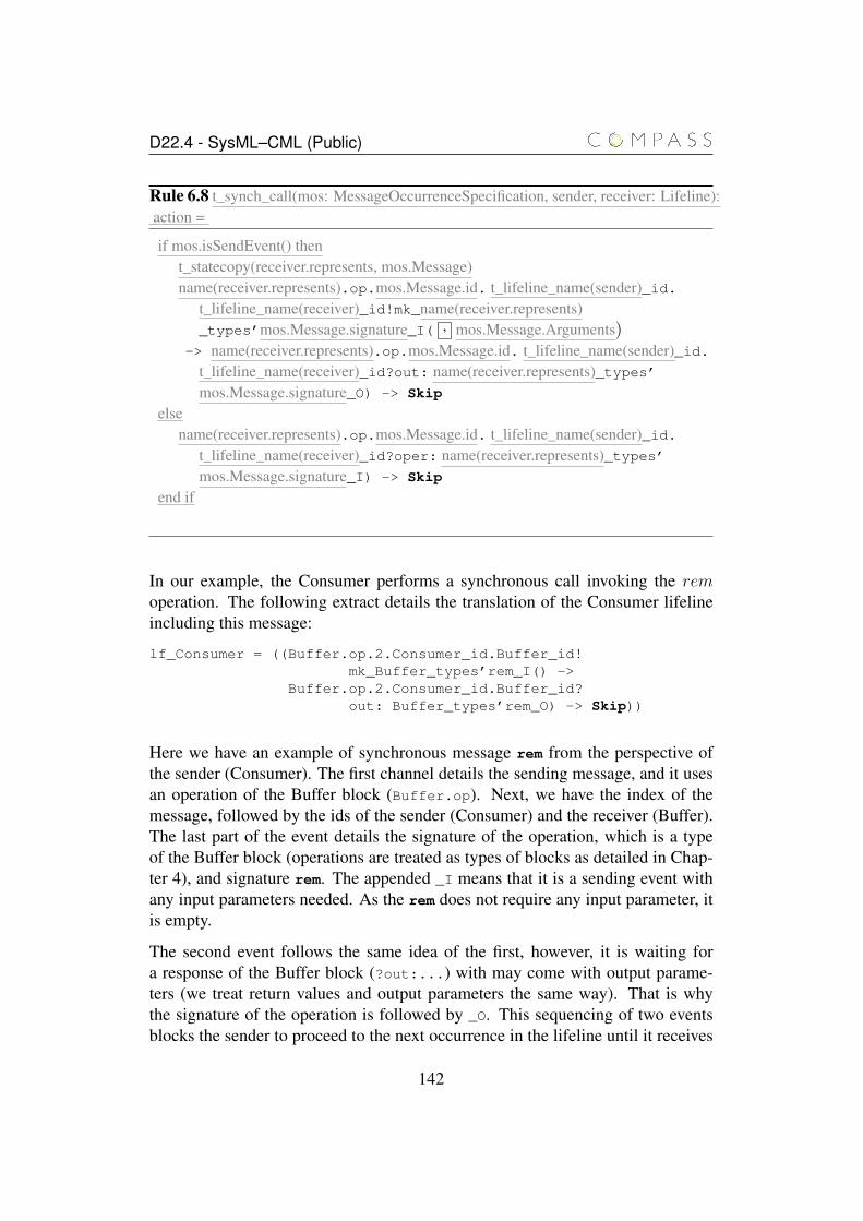
D22.4 - SysML–CML (Public)
Rule 6.8 t_synch_call(mos: MessageOccurrenceSpecification, sender, receiver: Lifeline):action =
if mos.isSendEvent() thent_statecopy(receiver.represents, mos.Message)name(receiver.represents).op.mos.Message.id. t_lifeline_name(sender)_id.
t_lifeline_name(receiver)_id!mk_name(receiver.represents)_types’mos.Message.signature_I( , mos.Message.Arguments)
-> name(receiver.represents).op.mos.Message.id. t_lifeline_name(sender)_id.t_lifeline_name(receiver)_id?out: name(receiver.represents)_types’mos.Message.signature_O) -> Skip
elsename(receiver.represents).op.mos.Message.id. t_lifeline_name(sender)_id.
t_lifeline_name(receiver)_id?oper: name(receiver.represents)_types’mos.Message.signature_I) -> Skip
end if
In our example, the Consumer performs a synchronous call invoking the remoperation. The following extract details the translation of the Consumer lifelineincluding this message:
lf_Consumer = ((Buffer.op.2.Consumer_id.Buffer_id!mk_Buffer_types’rem_I() ->
Buffer.op.2.Consumer_id.Buffer_id?out: Buffer_types’rem_O) -> Skip))
Here we have an example of synchronous message rem from the perspective ofthe sender (Consumer). The first channel details the sending message, and it usesan operation of the Buffer block (Buffer.op). Next, we have the index of themessage, followed by the ids of the sender (Consumer) and the receiver (Buffer).The last part of the event details the signature of the operation, which is a typeof the Buffer block (operations are treated as types of blocks as detailed in Chap-ter 4), and signature rem. The appended _I means that it is a sending event withany input parameters needed. As the rem does not require any input parameter, itis empty.
The second event follows the same idea of the first, however, it is waiting fora response of the Buffer block (?out:...) with may come with output parame-ters (we treat return values and output parameters the same way). That is whythe signature of the operation is followed by _O. This sequencing of two eventsblocks the sender to proceed to the next occurrence in the lifeline until it receives
142
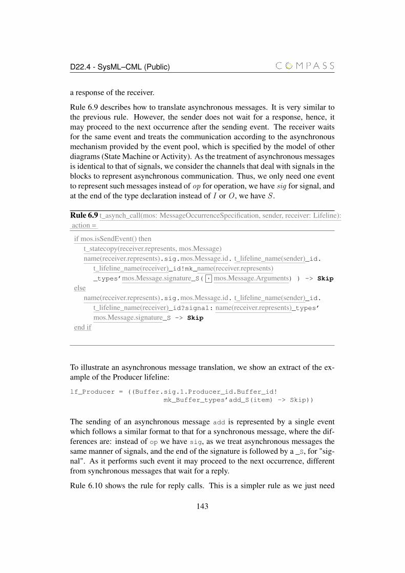
D22.4 - SysML–CML (Public)
a response of the receiver.
Rule 6.9 describes how to translate asynchronous messages. It is very similar tothe previous rule. However, the sender does not wait for a response, hence, itmay proceed to the next occurrence after the sending event. The receiver waitsfor the same event and treats the communication according to the asynchronousmechanism provided by the event pool, which is specified by the model of otherdiagrams (State Machine or Activity). As the treatment of asynchronous messagesis identical to that of signals, we consider the channels that deal with signals in theblocks to represent asynchronous communication. Thus, we only need one eventto represent such messages instead of op for operation, we have sig for signal, andat the end of the type declaration instead of I or O , we have S .
Rule 6.9 t_asynch_call(mos: MessageOccurrenceSpecification, sender, receiver: Lifeline):action =
if mos.isSendEvent() thent_statecopy(receiver.represents, mos.Message)name(receiver.represents).sig.mos.Message.id. t_lifeline_name(sender)_id.
t_lifeline_name(receiver)_id!mk_name(receiver.represents)_types’mos.Message.signature_S( , mos.Message.Arguments) ) -> Skip
elsename(receiver.represents).sig.mos.Message.id. t_lifeline_name(sender)_id.
t_lifeline_name(receiver)_id?signal: name(receiver.represents)_types’mos.Message.signature_S -> Skip
end if
To illustrate an asynchronous message translation, we show an extract of the ex-ample of the Producer lifeline:
lf_Producer = ((Buffer.sig.1.Producer_id.Buffer_id!mk_Buffer_types’add_S(item) -> Skip))
The sending of an asynchronous message add is represented by a single eventwhich follows a similar format to that for a synchronous message, where the dif-ferences are: instead of op we have sig, as we treat asynchronous messages thesame manner of signals, and the end of the signature is followed by a _S, for "sig-nal". As it performs such event it may proceed to the next occurrence, differentfrom synchronous messages that wait for a reply.
Rule 6.10 shows the rule for reply calls. This is a simpler rule as we just need
143
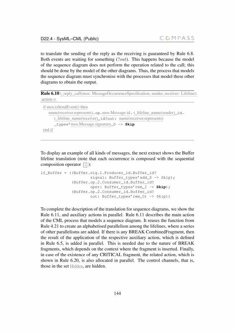
D22.4 - SysML–CML (Public)
to translate the sending of the reply as the receiving is guaranteed by Rule 6.8.Both events are waiting for something (?out). This happens because the modelof the sequence diagram does not perform the operation related to the call; thisshould be done by the model of the other diagrams. Thus, the process that modelsthe sequence diagram must synchronise with the processes that model these otherdiagrams to obtain the output.
Rule 6.10 t_reply_call(mos: MessageOccurrenceSpecification, sender, receiver: Lifeline):action =
if mos.isSendEvent() thenname(receiver.represents).op.mos.Message.id. t_lifeline_name(sender)_id.
t_lifeline_name(receiver)_id?out: name(receiver.represents)_types’mos.Message.signature_O -> Skip
end if
To display an example of all kinds of messages, the next extract shows the Bufferlifeline translation (note that each occurrence is composed with the sequentialcomposition operator ; ):
lf_Buffer = ((Buffer.sig.1.Producer_id.Buffer_id?signal: Buffer_types’add_S -> Skip);
(Buffer.op.2.Consumer_id.Buffer_id?oper: Buffer_types’rem_I -> Skip);
(Buffer.op.2.Consumer_id.Buffer_id?out: Buffer_types’rem_O) -> Skip))
To complete the description of the translation for sequence diagrams, we show theRule 6.11, and auxiliary actions in parallel. Rule 6.11 describes the main actionof the CML process that models a sequence diagram. It reuses the function fromRule 4.21 to create an alphabetised parallelism among the lifelines, where a seriesof other parallelisms are added. If there is any BREAK CombinedFragment, thenthe result of the application of the respective auxiliary action, which is definedin Rule 6.5, is added in parallel. This is needed due to the nature of BREAKfragments, which depends on the context where the fragment is inserted. Finally,in case of the existence of any CRITICAL fragment, the related action, which isshown in Rule 6.20, is also allocated in parallel. The control channels, that is,those in the set Hidden, are hidden.
144
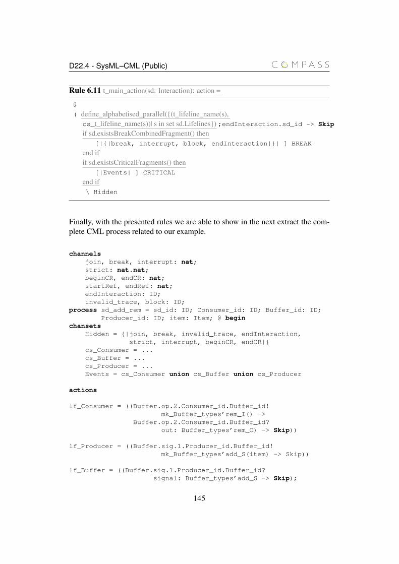
D22.4 - SysML–CML (Public)
Rule 6.11 t_main_action(sd: Interaction): action =
@
( define_alphabetised_parallel({(t_lifeline_name(s),cs_t_lifeline_name(s))| s in set sd.Lifelines}) ;endInteraction.sd_id -> Skip
if sd.existsBreakCombinedFragment() then[|{|break, interrupt, block, endInteraction|}| ] BREAK
end ifif sd.existsCriticalFragments() then
[|Events| ] CRITICAL
end if\ Hidden
Finally, with the presented rules we are able to show in the next extract the com-plete CML process related to our example.
channelsjoin, break, interrupt: nat;strict: nat.nat;beginCR, endCR: nat;startRef, endRef: nat;endInteraction: ID;invalid_trace, block: ID;
process sd_add_rem = sd_id: ID; Consumer_id: ID; Buffer_id: ID;Producer_id: ID; item: Item; @ begin
chansetsHidden = {|join, break, invalid_trace, endInteraction,
strict, interrupt, beginCR, endCR|}cs_Consumer = ...cs_Buffer = ...cs_Producer = ...Events = cs_Consumer union cs_Buffer union cs_Producer
actions
lf_Consumer = ((Buffer.op.2.Consumer_id.Buffer_id!mk_Buffer_types’rem_I() ->
Buffer.op.2.Consumer_id.Buffer_id?out: Buffer_types’rem_O) -> Skip))
lf_Producer = ((Buffer.sig.1.Producer_id.Buffer_id!mk_Buffer_types’add_S(item) -> Skip))
lf_Buffer = ((Buffer.sig.1.Producer_id.Buffer_id?signal: Buffer_types’add_S -> Skip);
145
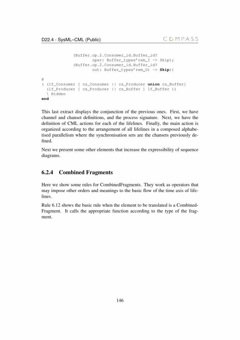
D22.4 - SysML–CML (Public)
(Buffer.op.2.Consumer_id.Buffer_id?oper: Buffer_types’rem_I -> Skip);
(Buffer.op.2.Consumer_id.Buffer_id?out: Buffer_types’rem_O) -> Skip))
@( (lf_Consumer [ cs_Consumer || cs_Producer union cs_Buffer]
(lf_Producer [ cs_Producer || cs_Buffer ] lf_Buffer ))\ Hidden
end
This last extract displays the conjunction of the previous ones. First, we havechannel and chanset definitions, and the process signature. Next, we have thedefinition of CML actions for each of the lifelines. Finally, the main action isorganized according to the arrangement of all lifelines in a composed alphabe-tised parallelism where the synchronisation sets are the chansets previously de-fined.
Next we present some other elements that increase the expressibility of sequencediagrams.
6.2.4 Combined Fragments
Here we show some rules for CombinedFragments. They work as operators thatmay impose other orders and meanings to the basic flow of the time axis of life-lines.
Rule 6.12 shows the basic rule when the element to be translated is a Combined-Fragment. It calls the appropriate function according to the type of the frag-ment.
146
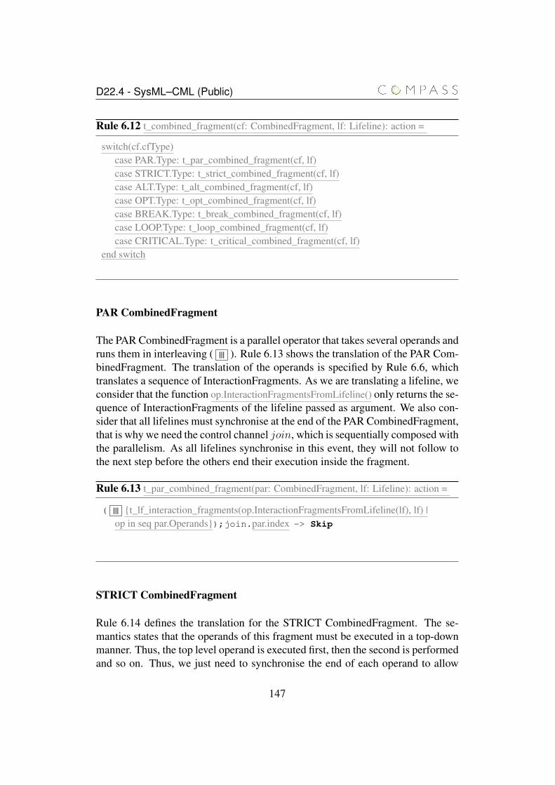
D22.4 - SysML–CML (Public)
Rule 6.12 t_combined_fragment(cf: CombinedFragment, lf: Lifeline): action =
switch(cf.cfType)case PAR.Type: t_par_combined_fragment(cf, lf)case STRICT.Type: t_strict_combined_fragment(cf, lf)case ALT.Type: t_alt_combined_fragment(cf, lf)case OPT.Type: t_opt_combined_fragment(cf, lf)case BREAK.Type: t_break_combined_fragment(cf, lf)case LOOP.Type: t_loop_combined_fragment(cf, lf)case CRITICAL.Type: t_critical_combined_fragment(cf, lf)
end switch
PAR CombinedFragment
The PAR CombinedFragment is a parallel operator that takes several operands andruns them in interleaving ( ||| ). Rule 6.13 shows the translation of the PAR Com-binedFragment. The translation of the operands is specified by Rule 6.6, whichtranslates a sequence of InteractionFragments. As we are translating a lifeline, weconsider that the function op.InteractionFragmentsFromLifeline() only returns the se-quence of InteractionFragments of the lifeline passed as argument. We also con-sider that all lifelines must synchronise at the end of the PAR CombinedFragment,that is why we need the control channel join, which is sequentially composed withthe parallelism. As all lifelines synchronise in this event, they will not follow tothe next step before the others end their execution inside the fragment.
Rule 6.13 t_par_combined_fragment(par: CombinedFragment, lf: Lifeline): action =
( ||| {t_lf_interaction_fragments(op.InteractionFragmentsFromLifeline(lf), lf) |op in seq par.Operands});join.par.index -> Skip
STRICT CombinedFragment
Rule 6.14 defines the translation for the STRICT CombinedFragment. The se-mantics states that the operands of this fragment must be executed in a top-downmanner. Thus, the top level operand is executed first, then the second is performedand so on. Thus, we just need to synchronise the end of each operand to allow
147
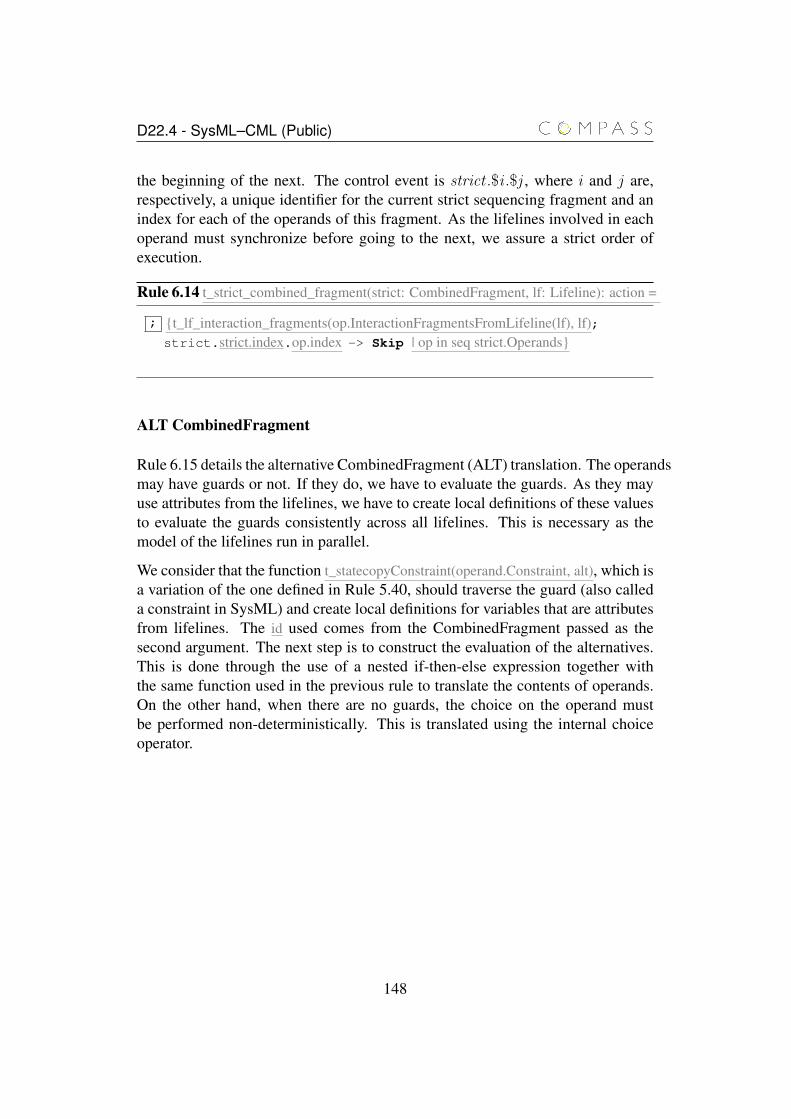
D22.4 - SysML–CML (Public)
the beginning of the next. The control event is strict .$i .$j , where i and j are,respectively, a unique identifier for the current strict sequencing fragment and anindex for each of the operands of this fragment. As the lifelines involved in eachoperand must synchronize before going to the next, we assure a strict order ofexecution.
Rule 6.14 t_strict_combined_fragment(strict: CombinedFragment, lf: Lifeline): action =
; {t_lf_interaction_fragments(op.InteractionFragmentsFromLifeline(lf), lf);strict.strict.index.op.index -> Skip | op in seq strict.Operands}
ALT CombinedFragment
Rule 6.15 details the alternative CombinedFragment (ALT) translation. The operandsmay have guards or not. If they do, we have to evaluate the guards. As they mayuse attributes from the lifelines, we have to create local definitions of these valuesto evaluate the guards consistently across all lifelines. This is necessary as themodel of the lifelines run in parallel.
We consider that the function t_statecopyConstraint(operand.Constraint, alt), which isa variation of the one defined in Rule 5.40, should traverse the guard (also calleda constraint in SysML) and create local definitions for variables that are attributesfrom lifelines. The id used comes from the CombinedFragment passed as thesecond argument. The next step is to construct the evaluation of the alternatives.This is done through the use of a nested if-then-else expression together withthe same function used in the previous rule to translate the contents of operands.On the other hand, when there are no guards, the choice on the operand mustbe performed non-deterministically. This is translated using the internal choiceoperator.
148
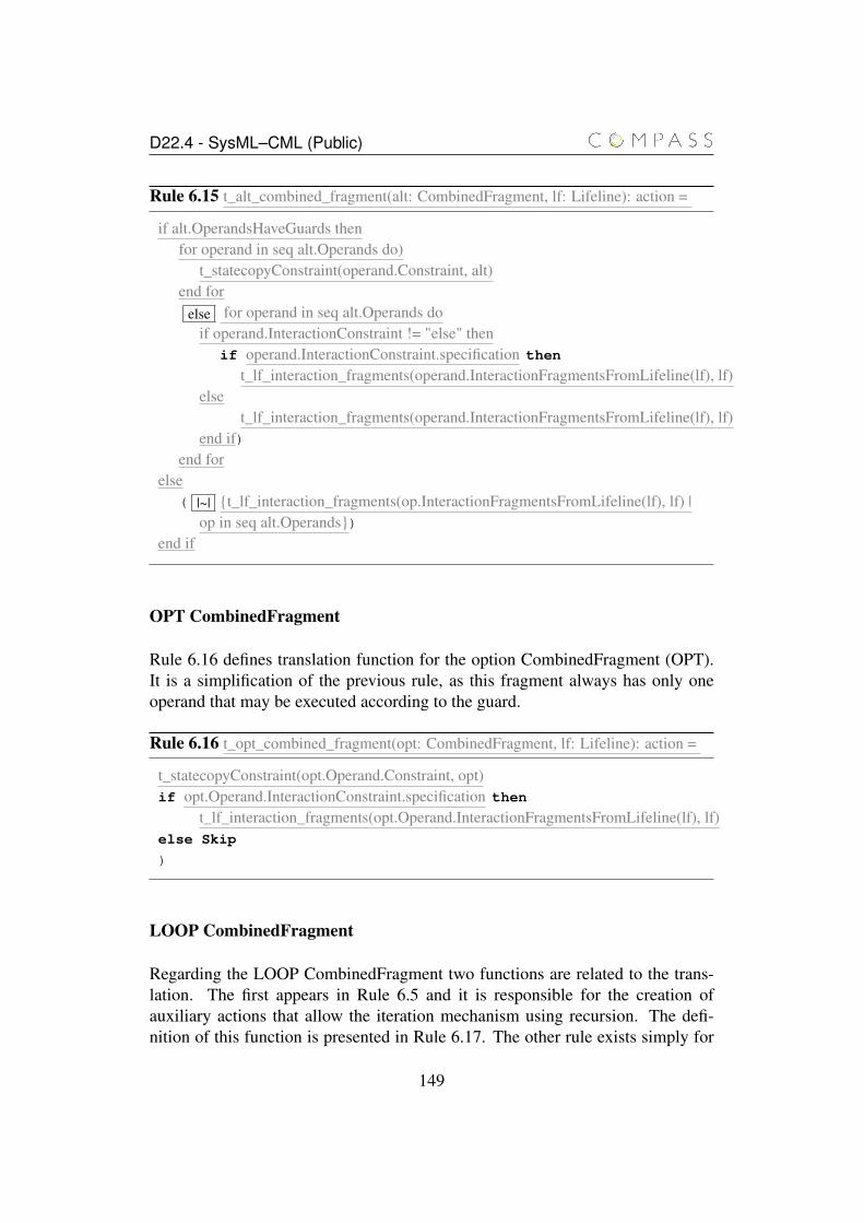
D22.4 - SysML–CML (Public)
Rule 6.15 t_alt_combined_fragment(alt: CombinedFragment, lf: Lifeline): action =
if alt.OperandsHaveGuards thenfor operand in seq alt.Operands do)
t_statecopyConstraint(operand.Constraint, alt)end for
else for operand in seq alt.Operands doif operand.InteractionConstraint != "else" then
if operand.InteractionConstraint.specification then
t_lf_interaction_fragments(operand.InteractionFragmentsFromLifeline(lf), lf)else
t_lf_interaction_fragments(operand.InteractionFragmentsFromLifeline(lf), lf)end if)
end forelse
( |~| {t_lf_interaction_fragments(op.InteractionFragmentsFromLifeline(lf), lf) |op in seq alt.Operands})
end if
OPT CombinedFragment
Rule 6.16 defines translation function for the option CombinedFragment (OPT).It is a simplification of the previous rule, as this fragment always has only oneoperand that may be executed according to the guard.
Rule 6.16 t_opt_combined_fragment(opt: CombinedFragment, lf: Lifeline): action =
t_statecopyConstraint(opt.Operand.Constraint, opt)if opt.Operand.InteractionConstraint.specification then
t_lf_interaction_fragments(opt.Operand.InteractionFragmentsFromLifeline(lf), lf)else Skip
)
LOOP CombinedFragment
Regarding the LOOP CombinedFragment two functions are related to the trans-lation. The first appears in Rule 6.5 and it is responsible for the creation ofauxiliary actions that allow the iteration mechanism using recursion. The defi-nition of this function is presented in Rule 6.17. The other rule exists simply for
149
D22.4 - SysML–CML (Public)
adding to the model of the lifeline the right loop auxiliary action; it is presentedin Rule 6.18.
Rule 6.17 creates the auxiliary loop actions needed for recursion. SysML providesa loop that takes parameters as input and behaves like a “for” loop. Depending onthe number of parameters for iteration, it can create three types of actions: withminimum and maximum number of iterations, only with maximum number ofiterations, and with no parameters for iterations. Another aspect is the existenceor not of InteractionConstraint, which changes the conditional evaluation of theloop.
150
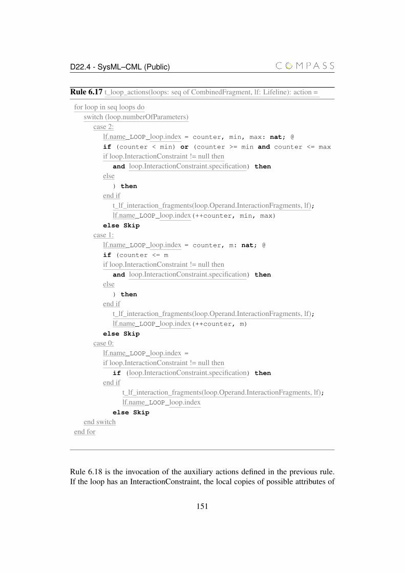
D22.4 - SysML–CML (Public)
Rule 6.17 t_loop_actions(loops: seq of CombinedFragment, lf: Lifeline): action =
for loop in seq loops doswitch (loop.numberOfParameters)
case 2:lf.name_LOOP_loop.index = counter, min, max: nat; @
if (counter < min) or (counter >= min and counter <= max
if loop.InteractionConstraint != null thenand loop.InteractionConstraint.specification) then
else) then
end ift_lf_interaction_fragments(loop.Operand.InteractionFragments, lf);lf.name_LOOP_loop.index(++counter, min, max)
else Skip
case 1:lf.name_LOOP_loop.index = counter, m: nat; @
if (counter <= m
if loop.InteractionConstraint != null thenand loop.InteractionConstraint.specification) then
else) then
end ift_lf_interaction_fragments(loop.Operand.InteractionFragments, lf);lf.name_LOOP_loop.index(++counter, m)
else Skip
case 0:lf.name_LOOP_loop.index =
if loop.InteractionConstraint != null thenif (loop.InteractionConstraint.specification) then
end ift_lf_interaction_fragments(loop.Operand.InteractionFragments, lf);lf.name_LOOP_loop.index
else Skip
end switchend for
Rule 6.18 is the invocation of the auxiliary actions defined in the previous rule.If the loop has an InteractionConstraint, the local copies of possible attributes of
151
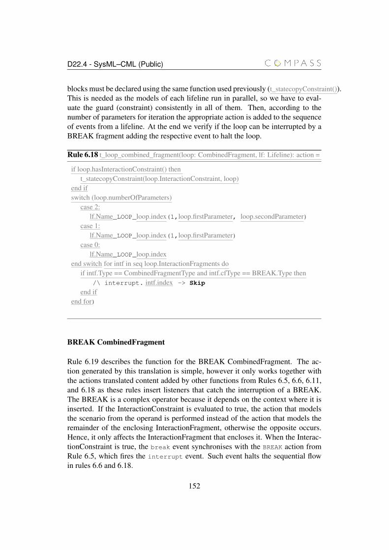
D22.4 - SysML–CML (Public)
blocks must be declared using the same function used previously (t_statecopyConstraint()).This is needed as the models of each lifeline run in parallel, so we have to eval-uate the guard (constraint) consistently in all of them. Then, according to thenumber of parameters for iteration the appropriate action is added to the sequenceof events from a lifeline. At the end we verify if the loop can be interrupted by aBREAK fragment adding the respective event to halt the loop.
Rule 6.18 t_loop_combined_fragment(loop: CombinedFragment, lf: Lifeline): action =
if loop.hasInteractionConstraint() thent_statecopyConstraint(loop.InteractionConstraint, loop)
end ifswitch (loop.numberOfParameters)
case 2:lf.Name_LOOP_loop.index(1,loop.firstParameter, loop.secondParameter)
case 1:lf.Name_LOOP_loop.index(1,loop.firstParameter)
case 0:lf.Name_LOOP_loop.index
end switch for intf in seq loop.InteractionFragments doif intf.Type == CombinedFragmentType and intf.cfType == BREAK.Type then
/\ interrupt. intf.index -> Skip
end ifend for)
BREAK CombinedFragment
Rule 6.19 describes the function for the BREAK CombinedFragment. The ac-tion generated by this translation is simple, however it only works together withthe actions translated content added by other functions from Rules 6.5, 6.6, 6.11,and 6.18 as these rules insert listeners that catch the interruption of a BREAK.The BREAK is a complex operator because it depends on the context where it isinserted. If the InteractionConstraint is evaluated to true, the action that modelsthe scenario from the operand is performed instead of the action that models theremainder of the enclosing InteractionFragment, otherwise the opposite occurs.Hence, it only affects the InteractionFragment that encloses it. When the Interac-tionConstraint is true, the break event synchronises with the BREAK action fromRule 6.5, which fires the interrupt event. Such event halts the sequential flowin rules 6.6 and 6.18.
152
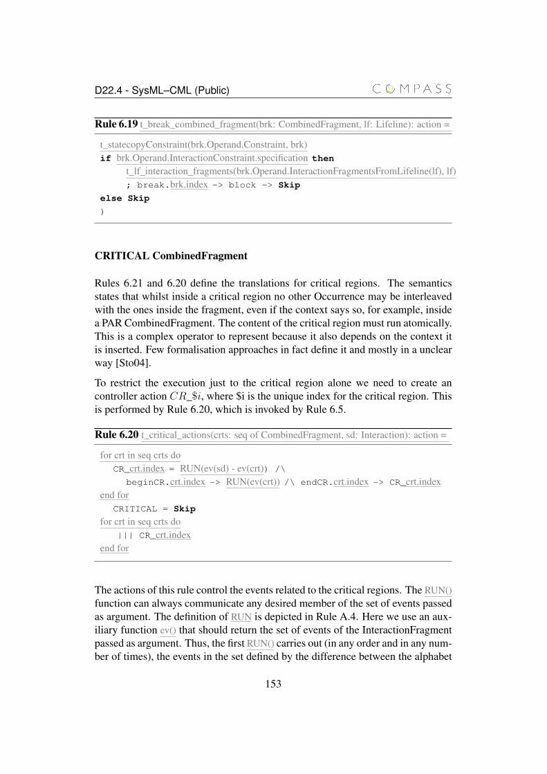
D22.4 - SysML–CML (Public)
Rule 6.19 t_break_combined_fragment(brk: CombinedFragment, lf: Lifeline): action =
t_statecopyConstraint(brk.Operand.Constraint, brk)if brk.Operand.InteractionConstraint.specification then
t_lf_interaction_fragments(brk.Operand.InteractionFragmentsFromLifeline(lf), lf); break.brk.index -> block -> Skip
else Skip
)
CRITICAL CombinedFragment
Rules 6.21 and 6.20 define the translations for critical regions. The semanticsstates that whilst inside a critical region no other Occurrence may be interleavedwith the ones inside the fragment, even if the context says so, for example, insidea PAR CombinedFragment. The content of the critical region must run atomically.This is a complex operator to represent because it also depends on the context itis inserted. Few formalisation approaches in fact define it and mostly in a unclearway [Sto04].
To restrict the execution just to the critical region alone we need to create ancontroller action CR_$i, where $i is the unique index for the critical region. Thisis performed by Rule 6.20, which is invoked by Rule 6.5.
Rule 6.20 t_critical_actions(crts: seq of CombinedFragment, sd: Interaction): action =
for crt in seq crts doCR_crt.index = RUN(ev(sd) - ev(crt)) /\
beginCR.crt.index -> RUN(ev(crt)) /\ endCR.crt.index -> CR_crt.indexend for
CRITICAL = Skip
for crt in seq crts do||| CR_crt.index
end for
The actions of this rule control the events related to the critical regions. The RUN()function can always communicate any desired member of the set of events passedas argument. The definition of RUN is depicted in Rule A.4. Here we use an aux-iliary function ev() that should return the set of events of the InteractionFragmentpassed as argument. Thus, the first RUN() carries out (in any order and in any num-ber of times), the events in the set defined by the difference between the alphabet
153
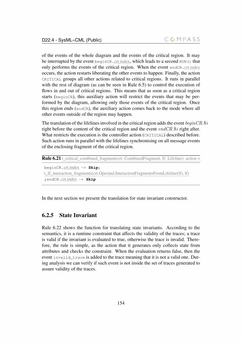
D22.4 - SysML–CML (Public)
of the events of the whole diagram and the events of the critical region. It maybe interrupted by the event beginCR.crt.index, which leads to a second RUN() thatonly performs the events of the critical region. When the event endCR.crt.indexoccurs, the action restarts liberating the other events to happen. Finally, the actionCRITICAL groups all other actions related to critical regions. It runs in parallelwith the rest of diagram (as can be seen in Rule 6.5) to control the execution offlows in and out of critical regions. This means that as soon as a critical regionstarts (beginCR), this auxiliary action will restrict the events that may be per-formed by the diagram, allowing only those events of the critical region. Oncethis region ends (endCR), the auxiliary action comes back to the mode where allother events outside of the region may happen.
The translation of the lifelines involved in the critical region adds the event beginCR.$iright before the content of the critical region and the event endCR.$i right after.What restricts the execution is the controller action (CRITICAL) described before.Such action runs in parallel with the lifelines synchronising on all message eventsof the enclosing fragment of the critical region.
Rule 6.21 t_critical_combined_fragment(crt: CombinedFragment, lf: Lifeline): action =
beginCR.crt.index -> Skip;
t_lf_interaction_fragments(crt.Operand.InteractionFragmentsFromLifeline(lf), lf);endCR.crt.index -> Skip
In the next section we present the translation for state invariant constructor.
6.2.5 State Invariant
Rule 6.22 shows the function for translating state invariants. According to thesemantics, it is a runtime constraint that affects the validity of the traces; a traceis valid if the invariant is evaluated to true, otherwise the trace is invalid. There-fore, the rule is simple, as the action that it generates only collects state fromattributes and checks the constraint. When the evaluation returns false, then theevent invalid_trace is added to the trace meaning that it is not a valid one. Dur-ing analysis we can verify if such event is not inside the set of traces generated toassure validity of the traces.
154

D22.4 - SysML–CML (Public)
Rule 6.22 t_state_invariant(si: InteractionFragment, lf: Lifeline): action =
t_statecopy(lf.represents, si)if si.InteractionConstraint.specification then Skip)
else invalid_trace -> Skip)
6.2.6 InteractionUse
The Rules 6.23, 6.24, 6.25, and 6.26 for InteractionUse are divided in two groups:one for translation of the reference itself and its relationship with the enclosingdiagram, and another for the translation of the lifelines that have an InteractionUseamong their collections of InteractionFragments.
When we encounter an InteractionUse along the translation of a lifeline we shouldtranslate it according to the Rule 6.23. This rule only generates two events, one forfiring the starting of the reference (startRef) and another for waiting until suchreference finishes (endRef). How such events relate to the model of the diagramsis discussed next in the presentation of a set of rules that defines the translation ofsequence diagrams that have InteractionUse elements.
Rule 6.23 t_interaction_use(iu: InteractionFragment): action =
startRef.iu.index -> endRef.iu.index -> Skip
A set of rules is needed when defining a sequence diagram with InteractionUseelements. The root function is defined by Rule 6.24.
Rule 6.24 t_complex_sd(sd: Interaction): seq of program paragraph =
for iu in seq sd.InteractionUse doif iu.hasIntercationUse() then
t_complex_sd(iu)else
t_simple_sd(iu, false)end ift_create_iu_processes(iu)
end fort_simple_sd(sd, true)t_create_complex_sd(sd)
155
D22.4 - SysML–CML (Public)
First of all it translates all Interactions related to InteractionUse elements insideitself. The next step is to create the CML process that represents the Interac-tionUse elements (t_create_iu_processes), which is discussed in Rule 6.25. Then,we invoke one of the first rules discussed in this chapter (Rule 6.1), which createsthe CML process for the enclosing diagram. However, this time we create it asan internal process (second argument of the function). This happens because sucha process is reused by the next function (t_create_complex_sd() from Rule 6.26),which combines all other processes previously created in a parallel.
Rule 6.25 starts by defining two auxiliary processes that are responsible for indi-cating the start (startRef) and the end (endRef) of the InteractionUse execution.They are needed because we cannot compose actions with other processes in aCML process definition. Next the InteractionUse is defined. It receives as argu-ments the identifier of the InteractionUse, followed by the references (IDs) fromthe lifelines of the enclosing diagrams and references for gates. Although we usethe term "gate", actually, it means a reference to lifeline that communicates somemessage through the gate. Finally, any arguments that it may need are defined asparameters of the process. The process itself is simply the sequential compositionof theSTARTREF process, followed by the process of the Interaction referred by theInteractionUse and, at last, the ENDREF process.
156
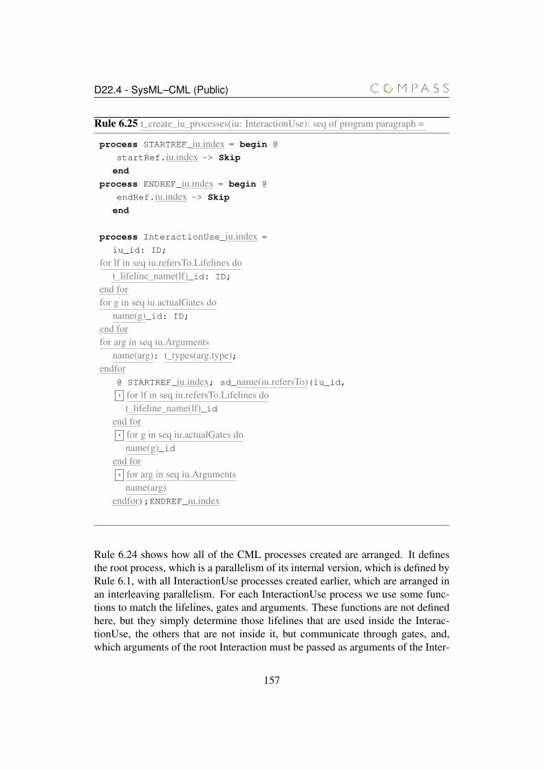
D22.4 - SysML–CML (Public)
Rule 6.25 t_create_iu_processes(iu: InteractionUse): seq of program paragraph =
process STARTREF_iu.index = begin @
startRef.iu.index -> Skip
end
process ENDREF_iu.index = begin @
endRef.iu.index -> Skip
end
process InteractionUse_iu.index =
iu_id: ID;
for lf in seq iu.refersTo.Lifelines dot_lifeline_name(lf)_id: ID;
end forfor g in seq iu.actualGates do
name(g)_id: ID;
end forfor arg in seq iu.Arguments
name(arg): t_types(arg.type);endfor
@ STARTREF_iu.index; sd_name(iu.refersTo)(iu_id,, for lf in seq iu.refersTo.Lifelines do
t_lifeline_name(lf)_idend for
, for g in seq iu.actualGates doname(g)_id
end for, for arg in seq iu.Arguments
name(arg)endfor);ENDREF_iu.index
Rule 6.24 shows how all of the CML processes created are arranged. It definesthe root process, which is a parallelism of its internal version, which is defined byRule 6.1, with all InteractionUse processes created earlier, which are arranged inan interleaving parallelism. For each InteractionUse process we use some func-tions to match the lifelines, gates and arguments. These functions are not definedhere, but they simply determine those lifelines that are used inside the Interac-tionUse, the others that are not inside it, but communicate through gates, and,which arguments of the root Interaction must be passed as arguments of the Inter-
157
D22.4 - SysML–CML (Public)
actionUse, respectively.
The alphabet of synchronisation are the startRef and endRef events added bythe message events that communicate through gates. We assume that such eventsare returned by the function gateMessages(sd), because such events depends of theexistence of gates in the InteractionUse.
Regarding the communication through gates, in order to make the message fromthe actual gate be the same that will be handled by the InteractionUse in its formalgate we need to perform some renaming. The function renameGateMessages(iu)does this work and it is detailed in Rule 6.27. Another assumption is that themessage from outside the InteractionUse knows the lifeline linked inside the In-teractionUse.
158
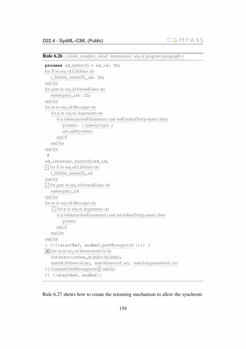
D22.4 - SysML–CML (Public)
Rule 6.26 t_create_complex_sd(sd: Interaction): seq of program paragraph =
process sd_name(sd) = sd_id: ID;
for lf in seq sd.Lifelines dot_lifeline_name(lf)_id: ID;
end forfor gate in seq sd.formalGates do
name(gate)_id: ID;
end forfor m in seq sd.Messages do
for p in seq m.Arguments doif p.isInteractionParameter() and notCreatedYet(p.name) then
p.name: t_types(p.type) ;aux.add(p.name)
end ifend for
end for@
sd_internal_name(sd)(sd_id,, for lf in seq sd.Lifelines do
t_lifeline_name(lf)_idend for, for gate in seq sd.formalGates do
name(gate)_idend forfor m in seq sd.Messages do
, for p in seq m.Arguments doif p.isInteractionParameter() and notAddedYet(p.name) then
p.nameend if
end forend for) [|{|startRef, endRef,gateMessages(sd) |}|] (
||| for iu in seq sd.InteractionUse doInteractionUse_iu.index(iu.index,matchLifelines(sd,iu), matchGates(sd, iu), matchArguments(sd, iu)
)[[renameGateMessages(iu)]] end for)\ {|startRef, endRef|}
Rule 6.27 shows how to create the renaming mechanism to allow the synchroni-
159

D22.4 - SysML–CML (Public)
sation of messages from formal gates to actual gates. After finding the actual gatecorresponding to the formal gate, it checks the direction of the message. Accord-ing to the direction and the type of the message, this function replaces the messageid of the formal by the id of the actual message.
Rule 6.27 renameGateMessages(iu: InteractionUse):seq of program paragraph =
, for formGate in seq iu.refersTo.formalGates dofor actualGate in seq iu.actualGates do
if name(formGate) == name(actualGate) thenif formGate.Mesage.sendEvent == formGate then
switch (formGate.Message.messageSort)case synchCall or reply:
name(formGate.Message.receiveEvent.Lifeline.represents).op.formGate.Message.id <-
name(formGate.Message.receiveEvent.Lifeline.represents).op.actualGate.Message.id case asynchCall:name(formGate.Message.receiveEvent.Lifeline.represents).sig.formGate.Message.id <-
name(formGate.Message.receiveEvent.Lifeline.represents).sig.actualGate.Message.id end switch)
elseswitch (formGate.Message.messageSort)
case synchCall or reply:name(actualGate.Message.receiveEvent.Lifeline.represents).op.formGate.Message.id <-
name(actualGate.Message.receiveEvent.Lifeline.represents).op.actualGate.Message.id
case asynchCall:name(actualGate.Message.receiveEvent.Lifeline.represents).sig.formGate.Message.id <-
name(actualGate.Message.receiveEvent.Lifeline.represents).sig.actualGate.Message.id
end switch)end if
end ifend for
end for
160
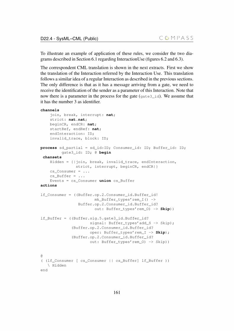
D22.4 - SysML–CML (Public)
To illustrate an example of application of these rules, we consider the two dia-grams described in Section 6.1 regarding InteractionUse (figures 6.2 and 6.3).
The correspondent CML translation is shown in the next extracts. First we showthe translation of the Interaction referred by the Interaction Use. This translationfollows a similar idea of a regular Interaction as described in the previous sections.The only difference is that as it has a message arriving from a gate, we need toreceive the identification of the sender as a parameter of this Interaction. Note thatnow there is a parameter in the process for the gate (gate3_id). We assume thatit has the number 3 as identifier.
channelsjoin, break, interrupt: nat;strict: nat.nat;beginCR, endCR: nat;startRef, endRef: nat;endInteraction: ID;invalid_trace, block: ID;
process sd_partial = sd_id:ID; Consumer_id: ID; Buffer_id: ID;gate3_id: ID; @ begin
chansetsHidden = {|join, break, invalid_trace, endInteraction,
strict, interrupt, beginCR, endCR|}cs_Consumer = ...cs_Buffer = ...Events = cs_Consumer union cs_Buffer
actions
lf_Consumer = ((Buffer.op.2.Consumer_id.Buffer_id!mk_Buffer_types’rem_I() ->
Buffer.op.2.Consumer_id.Buffer_id?out: Buffer_types’rem_O) -> Skip))
lf_Buffer = ((Buffer.sig.5.gate3_id.Buffer_id?signal: Buffer_types’add_S -> Skip);
(Buffer.op.2.Consumer_id.Buffer_id?oper: Buffer_types’rem_I -> Skip);
(Buffer.op.2.Consumer_id.Buffer_id?out: Buffer_types’rem_O) -> Skip))
@( (lf_Consumer [ cs_Consumer || cs_Buffer] lf_Buffer ))
\ Hiddenend
161
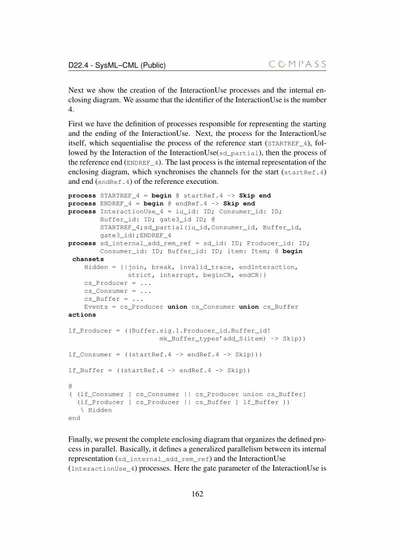
D22.4 - SysML–CML (Public)
Next we show the creation of the InteractionUse processes and the internal en-closing diagram. We assume that the identifier of the InteractionUse is the number4.
First we have the definition of processes responsible for representing the startingand the ending of the InteractionUse. Next, the process for the InteractionUseitself, which sequentialise the process of the reference start (STARTREF_4), fol-lowed by the Interaction of the InteractionUse(sd_partial), then the process ofthe reference end (ENDREF_4). The last process is the internal representation of theenclosing diagram, which synchronises the channels for the start (startRef.4)and end (endRef.4) of the reference execution.
process STARTREF_4 = begin @ startRef.4 -> Skip endprocess ENDREF_4 = begin @ endRef.4 -> Skip endprocess InteractionUse_4 = iu_id: ID; Consumer_id: ID;
Buffer_id: ID; gate3_id ID; @STARTREF_4;sd_partial(iu_id,Consumer_id, Buffer_id,gate3_id);ENDREF_4
process sd_internal_add_rem_ref = sd_id: ID; Producer_id: ID;Consumer_id: ID; Buffer_id: ID; item: Item; @ begin
chansetsHidden = {|join, break, invalid_trace, endInteraction,
strict, interrupt, beginCR, endCR|}cs_Producer = ...cs_Consumer = ...cs_Buffer = ...Events = cs_Producer union cs_Consumer union cs_Buffer
actions
lf_Producer = ((Buffer.sig.1.Producer_id.Buffer_id!mk_Buffer_types’add_S(item) -> Skip))
lf_Consumer = ((startRef.4 -> endRef.4 -> Skip)))
lf_Buffer = ((startRef.4 -> endRef.4 -> Skip))
@( (lf_Consumer [ cs_Consumer || cs_Producer union cs_Buffer]
(lf_Producer [ cs_Producer || cs_Buffer ] lf_Buffer ))\ Hidden
end
Finally, we present the complete enclosing diagram that organizes the defined pro-cess in parallel. Basically, it defines a generalized parallelism between its internalrepresentation (sd_internal_add_rem_ref) and the InteractionUse(InteractionUse_4) processes. Here the gate parameter of the InteractionUse is
162
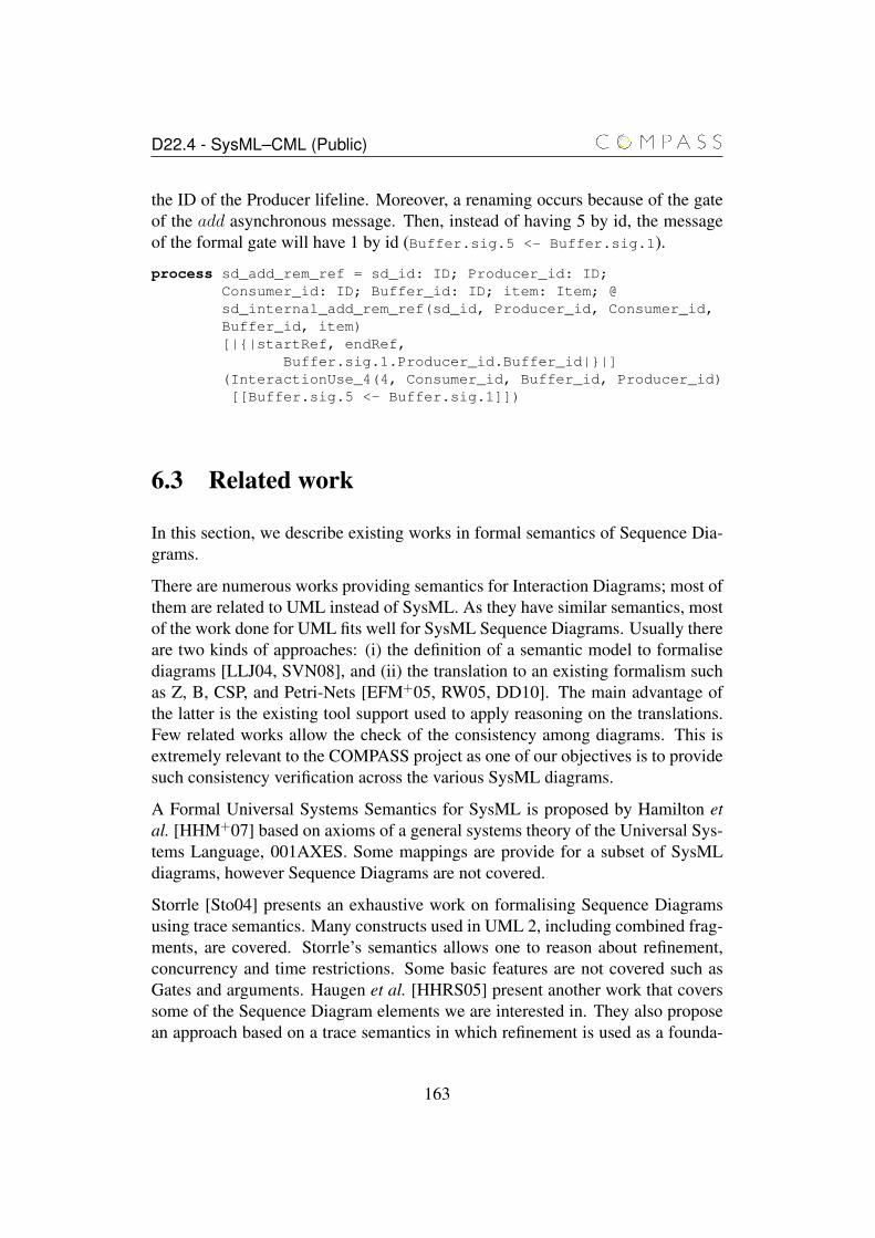
D22.4 - SysML–CML (Public)
the ID of the Producer lifeline. Moreover, a renaming occurs because of the gateof the add asynchronous message. Then, instead of having 5 by id, the messageof the formal gate will have 1 by id (Buffer.sig.5 <- Buffer.sig.1).
process sd_add_rem_ref = sd_id: ID; Producer_id: ID;Consumer_id: ID; Buffer_id: ID; item: Item; @sd_internal_add_rem_ref(sd_id, Producer_id, Consumer_id,Buffer_id, item)[|{|startRef, endRef,
Buffer.sig.1.Producer_id.Buffer_id|}|](InteractionUse_4(4, Consumer_id, Buffer_id, Producer_id)[[Buffer.sig.5 <- Buffer.sig.1]])
6.3 Related work
In this section, we describe existing works in formal semantics of Sequence Dia-grams.
There are numerous works providing semantics for Interaction Diagrams; most ofthem are related to UML instead of SysML. As they have similar semantics, mostof the work done for UML fits well for SysML Sequence Diagrams. Usually thereare two kinds of approaches: (i) the definition of a semantic model to formalisediagrams [LLJ04, SVN08], and (ii) the translation to an existing formalism suchas Z, B, CSP, and Petri-Nets [EFM+05, RW05, DD10]. The main advantage ofthe latter is the existing tool support used to apply reasoning on the translations.Few related works allow the check of the consistency among diagrams. This isextremely relevant to the COMPASS project as one of our objectives is to providesuch consistency verification across the various SysML diagrams.
A Formal Universal Systems Semantics for SysML is proposed by Hamilton etal. [HHM+07] based on axioms of a general systems theory of the Universal Sys-tems Language, 001AXES. Some mappings are provide for a subset of SysMLdiagrams, however Sequence Diagrams are not covered.
Storrle [Sto04] presents an exhaustive work on formalising Sequence Diagramsusing trace semantics. Many constructs used in UML 2, including combined frag-ments, are covered. Storrle’s semantics allows one to reason about refinement,concurrency and time restrictions. Some basic features are not covered such asGates and arguments. Haugen et al. [HHRS05] present another work that coverssome of the Sequence Diagram elements we are interested in. They also proposean approach based on a trace semantics in which refinement is used as a founda-
163
D22.4 - SysML–CML (Public)
tion for compositional analysis, verification and testing. Lund [Lun07] gives andoperational semantics for the Haugen’s denotational semantics. In both semantics,loop with constraint and the BREAK fragment are not covered.
Although the approaches by Storrle [Sto04] and by Haugen et al. [HHRS05] donot use a semantic model similar to CML, they are inspiring works as some im-portant discussions over complete and partial traces, global versus local view, andso on.
Dan and Danning [DD10] present an approach to semantic mapping specified us-ing QVT [OMG05] relations to CSP [Hoa85]. Their approach uses a notationsimilar to CML, so we could benefit from some of the ideas of their work. How-ever, very few constructs of UML 2 are covered.
Cavarra and Filipe [CKF05] proposed a technique using Object Constraint Lan-guage (OCL) templates to express liveness properties in UML Sequence Dia-grams. They give examples showing that certain liveness properties cannot beexpressed with assert or negate. Abstract state machines are used to enrich thesequence diagram in order to express such properties.
Cengarle [CMmuM05] gives an operational semantics for Sequence Diagrams.The author defines a semantic of negative fragments. Rules are given for each ofthe operators specifying whether a trace positively or negatively satisfies a frag-ment with that operator. The authors point out that with the basic interpretation ofnegative fragments it is easy to construct overspecified Interactions, i.e., an Inter-action that can be positively and negatively satisfied from the same trace.
Knapp and Wuttke [KW07] provide an operational semantics based on automaton,while Eicher et al. [EFM+05] use multivalued nets, which are a specific kindof Petri nets that allow parametrisation of messages and interactions. However,the latter does not provide enough information about the formalisation of someconstructs. The intuitions are only described textually.
Shen et al. [SVN08] propose a formalization using template semantics is pro-posed for UML 2 Sequence Diagrams. The approach gives an operational se-mantics for which the basic computation model is hierarchical transition systems(HTS).
Most of these works differ regarding three main aspects: the number of construc-tions they cover, the semantics of constructions whose official meaning is vaguelydefined, and the semantic domain used to formalise the semantics. The interestingaspect to notice is that when defining a semantics for Sequence Diagrams, somesemantic decisions must be taken in order to allow its use. Micksei and Waese-lynck [MW11] have provided an excellent survey on these semantic choices. We
164
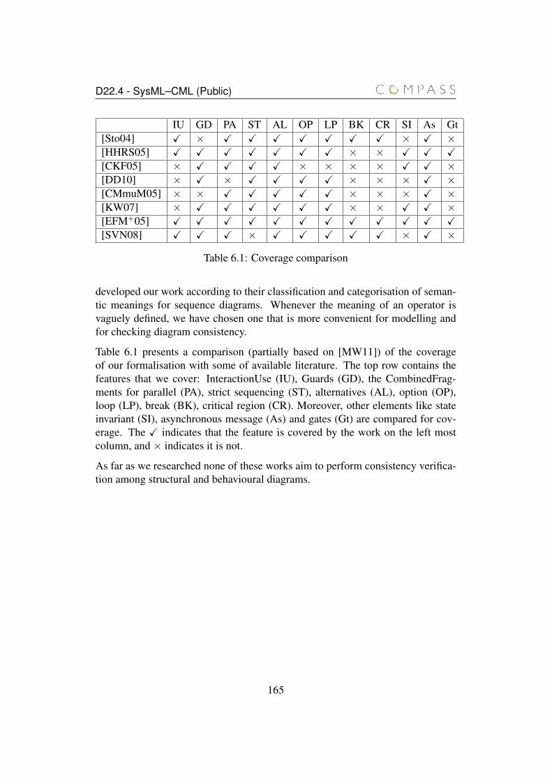
D22.4 - SysML–CML (Public)
IU GD PA ST AL OP LP BK CR SI As Gt[Sto04] X × X X X X X X X × X ×[HHRS05] X X X X X X X × × X X X[CKF05] × X X X X × × × × X X ×[DD10] × X × X X X X × × × X ×[CMmuM05] × × X X X X X × × × X ×[KW07] × X X X X X X × × X X ×[EFM+05] X X X X X X X X X X X X[SVN08] X X X × X X X X X × X ×
Table 6.1: Coverage comparison
developed our work according to their classification and categorisation of seman-tic meanings for sequence diagrams. Whenever the meaning of an operator isvaguely defined, we have chosen one that is more convenient for modelling andfor checking diagram consistency.
Table 6.1 presents a comparison (partially based on [MW11]) of the coverageof our formalisation with some of available literature. The top row contains thefeatures that we cover: InteractionUse (IU), Guards (GD), the CombinedFrag-ments for parallel (PA), strict sequencing (ST), alternatives (AL), option (OP),loop (LP), break (BK), critical region (CR). Moreover, other elements like stateinvariant (SI), asynchronous message (As) and gates (Gt) are compared for cov-erage. The X indicates that the feature is covered by the work on the left mostcolumn, and × indicates it is not.
As far as we researched none of these works aim to perform consistency verifica-tion among structural and behavioural diagrams.
165

Chapter 7
Activity diagrams
In this chapter, we formalise the translation of activity diagrams and illustrate itwith the support of a few examples. Whenever convenient, we use the example ofthe Producer-Consumer introduced in the previous chapters. As this example doesnot illustrate all translation rules we propose, some other examples are also intro-duced along this chapter. This chapter is organised as follows. In Section 7.1, weintroduced an initial example. The translation rules are presented in Section 7.2.Finally, we discuss related work in Section 7.3.
7.1 Examples
We depict two examples of activity diagrams, where they describe operations ofthe Buffer block. The operations are add and rem. These diagrams can be invokedby the state machine or other activity diagram in order to fulfill the behaviour ofsuch tasks.
The first diagram displayed in Figure 7.1 represents the Add activity. It has allkinds of activity nodes: action, control and object nodes. The beginning of itsbehaviour starts through the initial node and the activity parameter node item,which is of the type Item. A decision node checks if the size of the buffer isless than five (limit of the Buffer), so another item can be added, otherwise theactivity ends. When it is less than five, an opaque action is fired and it receivesas input through an input pin the item to be added. The content of the opaqueaction is CML code, which is executed when it can begin its processing. Suchcode just adds to the buffer the element received as parameter. After this actionis performed, the control edge leaving this action leads to an activity final node,
166

D22.4 - SysML–CML (Public)
which ends the diagram execution.
Figure 7.1: Activity Diagram: Adding an element to the Buffer
The Rem activity diagram removes an item from the buffer and returns it as out-put. Figure 7.2 shows the behaviour of such activity. It has no inputs, and after theinitial node, a decision node checks if there is at least one element to be removed,otherwise it ends the activity. In case it has elements, a call operation action isfired, which should deal with the task of removing an element of the buffer andreturning it as output. In this case, such task may be carried out by the blockitself, where the task may be described using an Action language, or the state ma-chine may address this operation call. This call operation action returns an output,which is put in its output pin. Next, this data is made available as output of theactivity by means of the activity parameter node Rem of the type Item. The twoedges leaving the action represent an object flow that transports the data to theactivity parameter node, and the other is a control flow that leads to the end of thediagram at an activity final node.
We use these examples to illustrate how the translation functions generate the re-spective CML code. SysML activities have their semantics based on token-flowsemantics of Petri nets. Tokens are used to hold values of input, output, and con-trol that flow from one action to another [FMS11]. To deal with control flow, wewill use a channel that is responsible for synchronisation between actions.
167
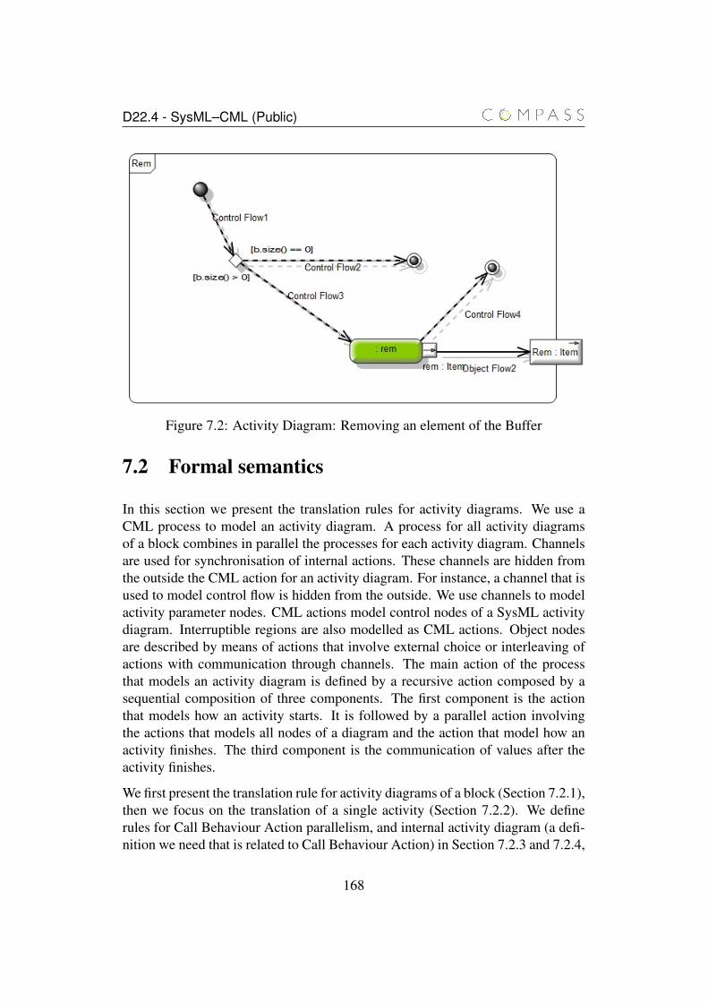
D22.4 - SysML–CML (Public)
Figure 7.2: Activity Diagram: Removing an element of the Buffer
7.2 Formal semantics
In this section we present the translation rules for activity diagrams. We use aCML process to model an activity diagram. A process for all activity diagramsof a block combines in parallel the processes for each activity diagram. Channelsare used for synchronisation of internal actions. These channels are hidden fromthe outside the CML action for an activity diagram. For instance, a channel that isused to model control flow is hidden from the outside. We use channels to modelactivity parameter nodes. CML actions model control nodes of a SysML activitydiagram. Interruptible regions are also modelled as CML actions. Object nodesare described by means of actions that involve external choice or interleaving ofactions with communication through channels. The main action of the processthat models an activity diagram is defined by a recursive action composed by asequential composition of three components. The first component is the actionthat models how an activity starts. It is followed by a parallel action involvingthe actions that models all nodes of a diagram and the action that model how anactivity finishes. The third component is the communication of values after theactivity finishes.
We first present the translation rule for activity diagrams of a block (Section 7.2.1),then we focus on the translation of a single activity (Section 7.2.2). We definerules for Call Behaviour Action parallelism, and internal activity diagram (a defi-nition we need that is related to Call Behaviour Action) in Section 7.2.3 and 7.2.4,
168

D22.4 - SysML–CML (Public)
respectively. We introduce the rules for translating how an activity starts and howan activity ends in Sections 7.2.5 and 7.2.7, respectively. The for rule interrupt-ible regions is presented in Section 7.2.6. The rules for actions, control nodes, andobject nodes are defined in Sections 7.2.8, 7.2.9, and 7.2.10, respectively.
7.2.1 Block Activity Diagrams
We start the translation using the function t_activity_diagrams defined in Rule 7.1.This is the root function for activity diagrams. The parameters of this functionprovide a sequence of activity diagrams and a block to which these activities be-long (when they define operations of the block), resulting in a sequence of pro-gram paragraphs. This function introduces channels related to control flow, and aprocess.
The channel control is used to deal with the flow of the control tokens in an ac-tivity diagram. The execution of an action or control node linked to a control flowis only allowed with the availability of the control token. The type of the channelcontrol is nat. Similarly to sequence diagrams, we assume a pre-processing ofan activity diagram so that each action node is given a unique identifier of typenat. So, through control we establish which action node can be executed. Chan-nel endDiagram is used to communicate that a diagram with an ID has finishedits execution because it reached a final activity node or, if a final activity node isnot present in a diagram, after writing output parameters or after sending signals.The type of channel endDiagram is defined by the activity identifier. The channelendFlow is used for indicating that we have executed an action that ends a flow,for instance, a Send Signal action without outgoing edges. The other cases thatend a flow are defined by a flow final node, and output activity parameters, whichonly have incoming edges. Channel interrupted is used to indicate that an in-terrupting edge of an interruptible region has been traversed. The interruption isrelated to a diagram, a block instance, and an interruptible region index. All thesechannels are internal to an activity diagram process and they will be hidden byusing a specific function to be presented later in this chapter.
By calling the function t_ad_channels(ad, block) for every activity diagram in thesequence ads received as argument, more channels are introduced to deal withcommunication that occurs among diagrams and inside diagrams. Also, the it-erative call to function t_activity_diagram provides a translation of every activitydiagram in ads.
The name of the process that the function t_activity_diagrams introduces is definedby the name of the block instance received as argument (name(block)) appended
169
D22.4 - SysML–CML (Public)
with _ads The process definition is given by the alphabetised parallelism givenby a call to function define_alphabetised_parallel with the following arguments: theactivity diagrams of block and a set of synchronisation events determined by thealphabet (of visible channels) of each diagram given by function alpha(ad).
Rule 7.1 t_activity_diagrams(ads: seq of Activity, block: Block): seq of program paragraph =
channels
control: nat;
endDiagram: ID;
endFlow: ID.nat;
interrupted: ID.ID.nat;
for ad in ads dot_ad_channels(ad, block)
end for
for ad in ads dot_activity_diagram(ad, block)
end for
process name(block)_ads = name(block)_id: ID @
define_alphabetised_parallel({(ad_name(ad)(name(block)_id),alpha(ad))| ad in seq ads})
The respective CML code generated by this rule for the Add and Rem activitydiagrams described earlier is displayed in the following extract.
channelscontrol: nat;endDiagram: ID;endFlow: ID.nat;interrupted: ID.ID.nat;...
process ad_Add = ...process ad_Rem = ...
process Buffer_ads = Buffer_id: ID @ad_Add(Buffer_id) [ {|...|} || {|...|} ] ad_Rem(Buffer_id)
In this extract, there are two processes (ad_Add and ad_Rem) for the activities Add
170
D22.4 - SysML–CML (Public)
andRem. The process Buffer_ads combines these two processes in parallel. Thechannels deal with control flow, indication of finalisation of a specific diagram,end of a flow, and indication that an interrupting edge has been traversed.
The function t_ad_channels (Rule 7.2) introduces channels for a specific activityad of a Block instance block. To start an activity, we must provide values forits input parameter nodes by means of channel startActivity. The types of pa-rameters of this channel are defined to be ID followed by the types of the activityparameter nodes that do not have incoming edges, but have outgoing edges. Inother words, they are used for input. After an activity finishes, it provides valuesby means of channel endActivity whose type is defined in a similar way to thatof startActivity. On the other hand, parameter nodes related to endActivity
have no outgoing edge, but have at least one incoming edge. Notice that the chan-nel names startActivity and endActivity are appended by an underscore (_)followed by the activity ID.
Similarly to an activity, a call behaviour action has channels for providing inputvalues and for obtaining output values. The channel named startActivity_CBA_
is appended by the diagram unique name given by id(ad); its type is given by thediagram identifier, the Call Behaviour Action identifier (natural), and the typesof the input activity parameter nodes. Channel endActivity_CBA_ is similar tostartActivity_CBA_, but the former is to get values that result from a Call Be-haviour Action execution.
Every object flow is related to a channel whose name is obj_ followed by a uniquename given to the model by id(ad), and edge index through which the object flows.The type of this channel is given by the type of the object flow source.
We introduce channels for the input and output pins of each action node. Com-munication through an input pin uses a channel named in_ followed by the actionname, the input pin edge index and id(ad). The type is given by the input pin type.Similarly, for communication through an output pin, we define channels namedout_ followed by id(ad), the action name and the output edge index.
171
D22.4 - SysML–CML (Public)
Rule 7.2 t_ad_channels(ad: Activity, block: Block): seq of channel =
startActivity_id(ad): ID . {t_types(param) | param in seq ad.Nodes(ActivityParameterNodes.Type) and param.IncomingEdges.size() == 0 andparam.OutgoingEdges.size() > 0};
endActivity_id(ad): ID . {t_types(param) | param in seq ad.Nodes(ActivityParameterNodes.Type) and param.OutgoingEdges.size() == 0 andparam.IncomingEdges.size() > 0};
for cba in seq ad.Nodes(CallBehaviour.Type) dostartActivity_CBA_id(ad): ID.nat
. { t_types(edge) | edge in cba.IncomingEdges(Object.Type) };endActivity_CBA_id(ad): ID.nat
. { t_types(edge) | edge in cba.OutgoingEdges(Object.Type) };end for
for objFlow in seq ad.ActivityEdges doobj_id(ad)_edge.index: t_types(objFlow.source);
end forfor action in seq ad.Nodes(Action.Type) do
for inPin in seq action.inputPins doin_id(ad)_name(action)_inPin.edge.index: t_types(inPin);
end forfor outPin in seq action.outputPins do
out_id(ad)_name(action)_outPin.edge.index: t_types(outPin);end for
end for
The respective CML code generated by Rule 7.2 regarding the additional channelsof the Add and Rem activity diagrams is displayed in the following extract (weassume that the IDs of the diagrams are their own names):
channels...startActivity_Add: ID.Item;endActivity_Add: ID;obj_Add_1: Item;in_Add_OpaqueAction1_1: Item;
startActivity_Rem: ID;endActivity_Rem: ID.Item;
172
D22.4 - SysML–CML (Public)
obj_Rem_1: Item;out_Rem_rem_1: Item;...
In the next section, we introduce the function to translate a single activity dia-gram.
7.2.2 Single Activity Diagram
The function t_activity_diagram (Rule 7.3) gives as results two process definitions.The first process results from a call to t_ad_internal_process and is related to thenodes of an activity diagram of a block. The second process is named ad_ fol-lowed by the name of the activity diagram. It is parametrised by a block identifier.The process definition is given by a generalised parallelism of two processes: theone introduced by calling function t_ad_internal_process and other one for Call Be-haviour actions. When a Call Behaviour action is to be executed, the process thatmodels the diagram that requests such execution must synchronise with the actionmodel in the channel that allows the model of a Call Behavior action to start itsexecution. After this, the action that was called synchronises with the diagramprocess in a channel to indicate that it has finished. In this way, the diagram pro-cess gets back control.
Rule 7.3 t_activity_diagram(ad: Activity, block: Block): seq of program paragraph =
t_ad_internal_process(ad, block)process ad_name(ad) = name(block)_id: ID; @
ad_internal_name(ad)(name(block)_id)t_ad_cba_parallel(ad, block)
Next, we illustrate in the following extract the application of Rule 7.3 by showingthe generated CML code for the Add and Rem activity diagrams (as they do nothave call behaviour actions they are reduced to their internal CML process):
channels...
process ad_internal_Add = ...
process ad_Add = Buffer_id: ID; @ ad_internal_Add(Buffer_id)
process ad_internal_Rem = ...
173
D22.4 - SysML–CML (Public)
process ad_Rem = Buffer_id: ID; @ ad_internal_Rem(Buffer_id)
7.2.3 Call Behaviour Action Parallelism
We use the function t_ad_cba_parallel (Rule 7.4), if there is at least one Call Be-haviour action in a diagram, to introduce channels used for synchronisation be-tween the diagram model and call behaviour actions models. They run in parallelwithout synchronising. This function t_ad_cba_parallel has an activity identifica-tion and a block instance as arguments.
The channels whose names begin with startActivity_CBA_ are used for syn-chronisation between a diagram model and call behaviour action (CBA) model, sothat the CBA model starts its execution. The channel name is composed by the ac-tivity unique id given by id(ad), the block name appended with _id, and the call be-haviour action index. The channels whose names begin with endActivity_CBA_
are used for synchronisation between a CBA action model and a diagram model,indicating the end of a CBA execution. Every CBA action model has these twochannels.
Rule 7.4 t_ad_cba_parallel(ad: Activity, block: Block): program paragraph =
if ad.Nodes(CallBehaviour.Type).size > 0[|{
, { startActivity_CBA_id(ad).name(block)_id.cba.indexendActivity_CBA_id(ad).name(block)_id.cba.index| cba in seq ad.Nodes(CallBehaviour.Type)}
}|]
( ||| { ad_name(cba_ad)[[ startActivity_id(cba_ad).name(block)
<- startActivity_CBA_id(ad).name(block)_id.cba.index,endActivity_id(cba_ad).name(block)
<- endActivity_CBA_id(ad).name(block)_id.cba.index ]]
| cba in seq ad.Nodes(CallBehaviour.Type),cba_ad == cba.behaviour.activity})
end if
The CML actions for the Call Behaviour actions are executed in parallel withoutsynchronising. The channel name that begins with startActivity_ of each ac-
174
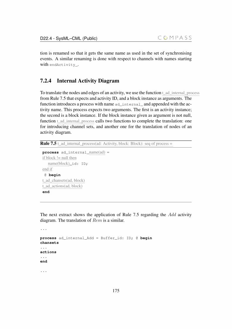
D22.4 - SysML–CML (Public)
tion is renamed so that it gets the same name as used in the set of synchronisingevents. A similar renaming is done with respect to channels with names startingwith endActivity_.
7.2.4 Internal Activity Diagram
To translate the nodes and edges of an activity, we use the function t_ad_internal_processfrom Rule 7.5 that expects and activity ID, and a block instance as arguments. Thefunction introduces a process with name ad_internal_ and appended with the ac-tivity name. This process expects two arguments. The first is an activity instance;the second is a block instance. If the block instance given as argument is not null,function t_ad_internal_process calls two functions to complete the translation: onefor introducing channel sets, and another one for the translation of nodes of anactivity diagram.
Rule 7.5 t_ad_internal_process(ad: Activity, block: Block): seq of process =
process ad_internal_name(ad) =if block != null then
name(block)_id: ID;
end if@ begin
t_ad_chansets(ad, block)t_ad_actions(ad, block)end
The next extract shows the application of Rule 7.5 regarding the Add activitydiagram. The translation of Rem is a similar.
...
process ad_internal_Add = Buffer_id: ID; @ beginchansets...actions...end
...
175
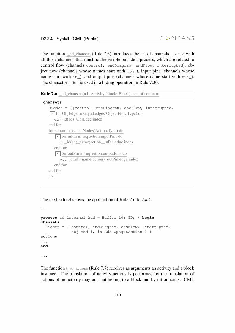
D22.4 - SysML–CML (Public)
The function t_ad_chansets (Rule 7.6) introduces the set of channels Hidden withall those channels that must not be visible outside a process, which are related tocontrol flow (channels control, endDiagram, endFlow, interrupted), ob-ject flow (channels whose names start with obj_), input pins (channels whosename start with in_), and output pins (channels whose name start with out_).The chanset Hidden is used in a hiding operation in Rule 7.30.
Rule 7.6 t_ad_chansets(ad: Activity, block: Block): seq of action =
chansets
Hidden = {|control, endDiagram, endFlow, interrupted,, for ObjEdge in seq ad.edges(ObjectFlow.Type) doobj_id(ad)_ObjEdge.index
end forfor action in seq ad.Nodes(Action.Type) do
, for inPin in seq action.inputPins doin_id(ad)_name(action)_inPin.edge.index
end for, for outPin in seq action.outputPins doout_id(ad)_name(action)_outPin.edge.index
end forend for|}
The next extract shows the application of Rule 7.6 to Add.
...
process ad_internal_Add = Buffer_id: ID; @ beginchansets
Hidden = {|control, endDiagram, endFlow, interrupted,obj_Add_1, in_Add_OpaqueAction_1|}
actions...end
...
The function t_ad_actions (Rule 7.7) receives as arguments an activity and a blockinstance. The translation of activity actions is performed by the translation ofactions of an activity diagram that belong to a block and by introducing a CML
176
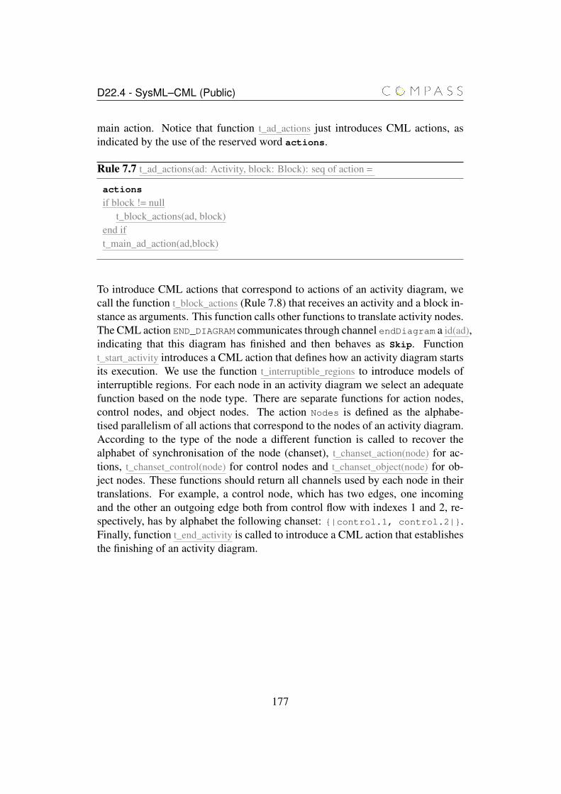
D22.4 - SysML–CML (Public)
main action. Notice that function t_ad_actions just introduces CML actions, asindicated by the use of the reserved word actions.
Rule 7.7 t_ad_actions(ad: Activity, block: Block): seq of action =
actions
if block != nullt_block_actions(ad, block)
end ift_main_ad_action(ad,block)
To introduce CML actions that correspond to actions of an activity diagram, wecall the function t_block_actions (Rule 7.8) that receives an activity and a block in-stance as arguments. This function calls other functions to translate activity nodes.The CML action END_DIAGRAM communicates through channel endDiagram a id(ad),indicating that this diagram has finished and then behaves as Skip. Functiont_start_activity introduces a CML action that defines how an activity diagram startsits execution. We use the function t_interruptible_regions to introduce models ofinterruptible regions. For each node in an activity diagram we select an adequatefunction based on the node type. There are separate functions for action nodes,control nodes, and object nodes. The action Nodes is defined as the alphabe-tised parallelism of all actions that correspond to the nodes of an activity diagram.According to the type of the node a different function is called to recover thealphabet of synchronisation of the node (chanset), t_chanset_action(node) for ac-tions, t_chanset_control(node) for control nodes and t_chanset_object(node) for ob-ject nodes. These functions should return all channels used by each node in theirtranslations. For example, a control node, which has two edges, one incomingand the other an outgoing edge both from control flow with indexes 1 and 2, re-spectively, has by alphabet the following chanset: {|control.1, control.2|}.Finally, function t_end_activity is called to introduce a CML action that establishesthe finishing of an activity diagram.
177
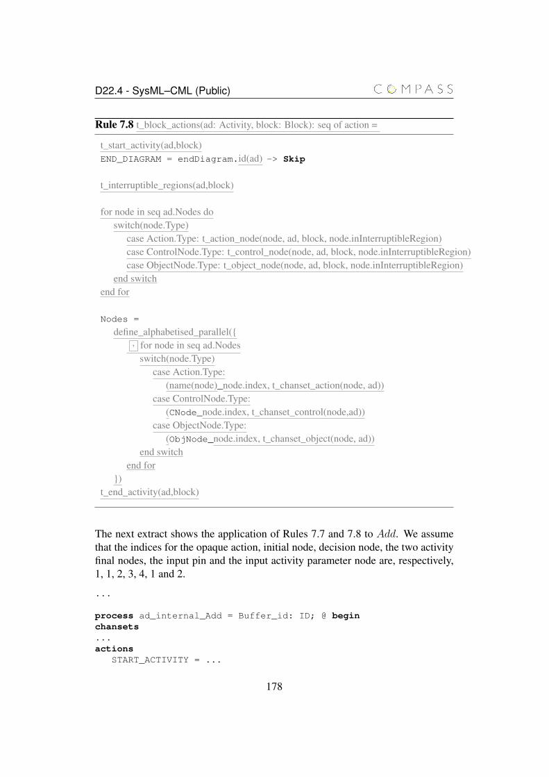
D22.4 - SysML–CML (Public)
Rule 7.8 t_block_actions(ad: Activity, block: Block): seq of action =
t_start_activity(ad,block)END_DIAGRAM = endDiagram.id(ad) -> Skip
t_interruptible_regions(ad,block)
for node in seq ad.Nodes doswitch(node.Type)
case Action.Type: t_action_node(node, ad, block, node.inInterruptibleRegion)case ControlNode.Type: t_control_node(node, ad, block, node.inInterruptibleRegion)case ObjectNode.Type: t_object_node(node, ad, block, node.inInterruptibleRegion)
end switchend for
Nodes =
define_alphabetised_parallel({, for node in seq ad.Nodes
switch(node.Type)case Action.Type:
(name(node)_node.index, t_chanset_action(node, ad))case ControlNode.Type:
(CNode_node.index, t_chanset_control(node,ad))case ObjectNode.Type:
(ObjNode_node.index, t_chanset_object(node, ad))end switch
end for})
t_end_activity(ad,block)
The next extract shows the application of Rules 7.7 and 7.8 to Add. We assumethat the indices for the opaque action, initial node, decision node, the two activityfinal nodes, the input pin and the input activity parameter node are, respectively,1, 1, 2, 3, 4, 1 and 2.
...
process ad_internal_Add = Buffer_id: ID; @ beginchansets...actions
START_ACTIVITY = ...
178
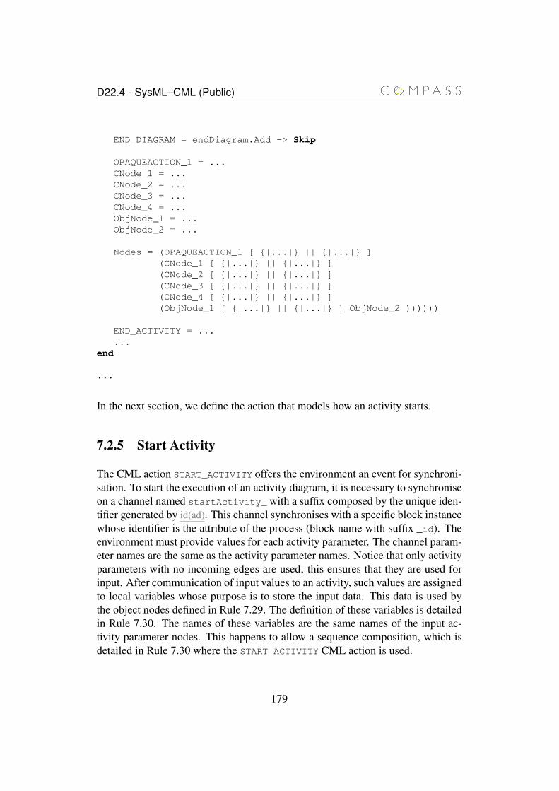
D22.4 - SysML–CML (Public)
END_DIAGRAM = endDiagram.Add -> Skip
OPAQUEACTION_1 = ...CNode_1 = ...CNode_2 = ...CNode_3 = ...CNode_4 = ...ObjNode_1 = ...ObjNode_2 = ...
Nodes = (OPAQUEACTION_1 [ {|...|} || {|...|} ](CNode_1 [ {|...|} || {|...|} ](CNode_2 [ {|...|} || {|...|} ](CNode_3 [ {|...|} || {|...|} ](CNode_4 [ {|...|} || {|...|} ](ObjNode_1 [ {|...|} || {|...|} ] ObjNode_2 ))))))
END_ACTIVITY = ......
end
...
In the next section, we define the action that models how an activity starts.
7.2.5 Start Activity
The CML action START_ACTIVITY offers the environment an event for synchroni-sation. To start the execution of an activity diagram, it is necessary to synchroniseon a channel named startActivity_ with a suffix composed by the unique iden-tifier generated by id(ad). This channel synchronises with a specific block instancewhose identifier is the attribute of the process (block name with suffix _id). Theenvironment must provide values for each activity parameter. The channel param-eter names are the same as the activity parameter names. Notice that only activityparameters with no incoming edges are used; this ensures that they are used forinput. After communication of input values to an activity, such values are assignedto local variables whose purpose is to store the input data. This data is used bythe object nodes defined in Rule 7.29. The definition of these variables is detailedin Rule 7.30. The names of these variables are the same names of the input ac-tivity parameter nodes. This happens to allow a sequence composition, which isdetailed in Rule 7.30 where the START_ACTIVITY CML action is used.
179
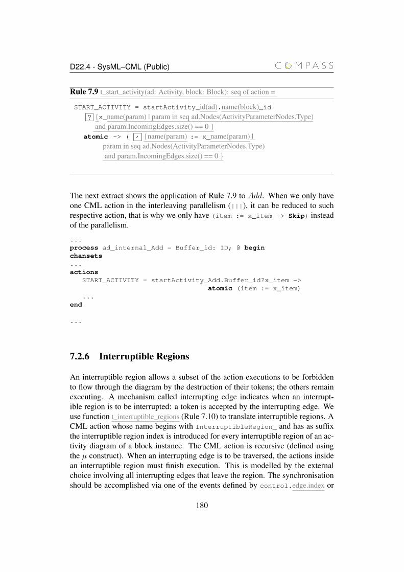
D22.4 - SysML–CML (Public)
Rule 7.9 t_start_activity(ad: Activity, block: Block): seq of action =
START_ACTIVITY = startActivity_id(ad).name(block)_id? {x_name(param) | param in seq ad.Nodes(ActivityParameterNodes.Type)
and param.IncomingEdges.size() == 0 }atomic -> ( , {name(param) := x_name(param) |
param in seq ad.Nodes(ActivityParameterNodes.Type)and param.IncomingEdges.size() == 0 }
The next extract shows the application of Rule 7.9 to Add. When we only haveone CML action in the interleaving parallelism (|||), it can be reduced to suchrespective action, that is why we only have (item := x_item -> Skip) insteadof the parallelism.
...process ad_internal_Add = Buffer_id: ID; @ beginchansets...actions
START_ACTIVITY = startActivity_Add.Buffer_id?x_item ->atomic (item := x_item)
...end
...
7.2.6 Interruptible Regions
An interruptible region allows a subset of the action executions to be forbiddento flow through the diagram by the destruction of their tokens; the others remainexecuting. A mechanism called interrupting edge indicates when an interrupt-ible region is to be interrupted: a token is accepted by the interrupting edge. Weuse function t_interruptible_regions (Rule 7.10) to translate interruptible regions. ACML action whose name begins with InterruptibleRegion_ and has as suffixthe interruptible region index is introduced for every interruptible region of an ac-tivity diagram of a block instance. The CML action is recursive (defined usingthe µ construct). When an interrupting edge is to be traversed, the actions insidean interruptible region must finish execution. This is modelled by the externalchoice involving all interrupting edges that leave the region. The synchronisationshould be accomplished via one of the events defined by control.edge.index or
180
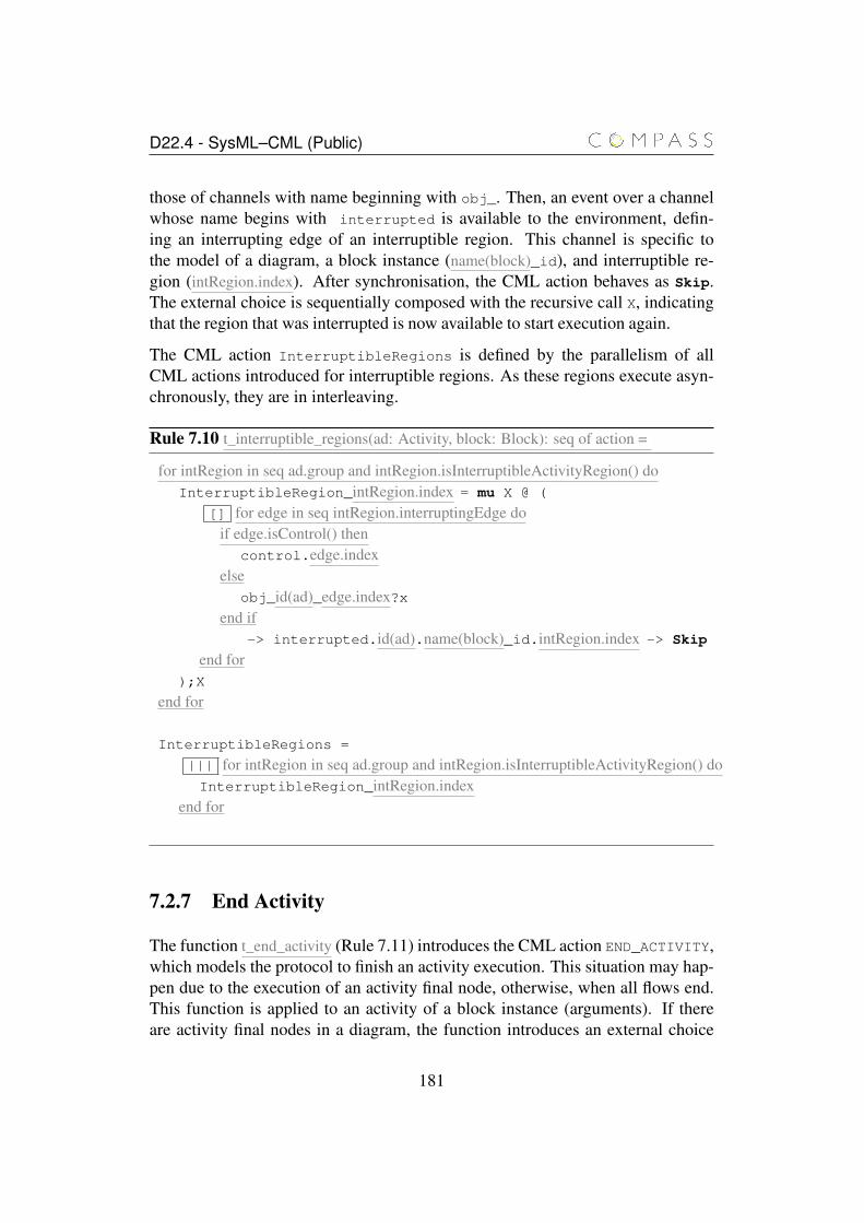
D22.4 - SysML–CML (Public)
those of channels with name beginning with obj_. Then, an event over a channelwhose name begins with interrupted is available to the environment, defin-ing an interrupting edge of an interruptible region. This channel is specific tothe model of a diagram, a block instance (name(block)_id), and interruptible re-gion (intRegion.index). After synchronisation, the CML action behaves as Skip.The external choice is sequentially composed with the recursive call X, indicatingthat the region that was interrupted is now available to start execution again.
The CML action InterruptibleRegions is defined by the parallelism of allCML actions introduced for interruptible regions. As these regions execute asyn-chronously, they are in interleaving.
Rule 7.10 t_interruptible_regions(ad: Activity, block: Block): seq of action =
for intRegion in seq ad.group and intRegion.isInterruptibleActivityRegion() doInterruptibleRegion_intRegion.index = mu X @ (
[] for edge in seq intRegion.interruptingEdge doif edge.isControl() then
control.edge.indexelse
obj_id(ad)_edge.index?xend if
-> interrupted.id(ad).name(block)_id.intRegion.index -> Skip
end for);X
end for
InterruptibleRegions =
||| for intRegion in seq ad.group and intRegion.isInterruptibleActivityRegion() doInterruptibleRegion_intRegion.index
end for
7.2.7 End Activity
The function t_end_activity (Rule 7.11) introduces the CML action END_ACTIVITY,which models the protocol to finish an activity execution. This situation may hap-pen due to the execution of an activity final node, otherwise, when all flows end.This function is applied to an activity of a block instance (arguments). If thereare activity final nodes in a diagram, the function introduces an external choice
181
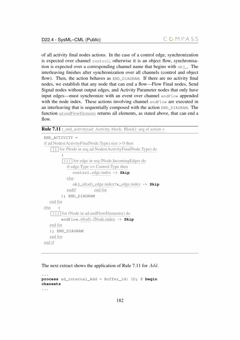
D22.4 - SysML–CML (Public)
of all activity final nodes actions. In the case of a control edge, synchronizationis expected over channel control; otherwise it is an object flow, synchronisa-tion is expected over a corresponding channel name that begins with obj_. Theinterleaving finishes after synchronization over all channels (control and objectflow). Then, the action behaves as END_DIAGRAM. If there are no activity finalnodes, we establish that any node that can end a flow—Flow Final nodes, SendSignal nodes without output edges, and Activity Parameter nodes that only haveinput edges—must synchronize with an event over channel endFlow appendedwith the node index. These actions involving channel endFlow are executed inan interleaving that is sequentially composed with the action END_DIAGRAM. Thefunction ad.endFlowElements returns all elements, as stated above, that can end aflow.
Rule 7.11 t_end_activity(ad: Activity, block: Block): seq of action =
END_ACTIVITY =
if ad.Nodes(ActivityFinalNode.Type).size > 0 then[] for fNode in seq ad.Nodes(ActivityFinalNode.Type) do
(
||| for edge in seq fNode.IncomingEdges doif edge.Type == Control.Type then
control.edge.index -> Skip
elseobj_id(ad)_edge.index?x_edge.index -> Skip
endif end for); END_DIAGRAM
end forelse (
||| for fNode in ad.endFlowElements() doendFlow.id(ad).fNode.index -> Skip
end for); END_DIAGRAM
end forend if
The next extract shows the application of Rule 7.11 for Add.
...process ad_internal_Add = Buffer_id: ID; @ beginchansets...
182

D22.4 - SysML–CML (Public)
actions...END_ACTIVITY = (control.3 -> Skip);END_DIAGRAM
[] (control.4 -> Skip);END_DIAGRAM...
end
...
The action END_ACTIVITY models that the activity Add finishes after synchroni-sation on events control.3 or control.4.
7.2.8 Actions
The function t_action_node Rule 7.12 deals with the translation of an action node.It receives as arguments an action node to be translated, the activity diagram towhich the action belongs, a block instance from which we translate the diagram,and the diagram interruptible regions. This function introduces a CML action witha name composed by the SysML action name appended with an underscore andthe action node index.
In SysML, every action execution finishes when the executing diagram finishesexecution. If the action is part of an interruptible region, however its executionfinishes when the interrupting edge of the region to which it belongs accepts a to-ken. Notice that it is possible to have nested interruptible regions, so that when aninterruptible region finishes its execution, actions of any nested interruptible re-gion must also finish execution. The boolean variable end_guard indicates whenan action can have its execution finished. This variable is used as the guard ofa guarded action: if it is true, then the action after the guard is enabled. So, forevery action, function t_action_node declares end_guard, a boolean variable, withtrue as initial value.
The CML action for a SysML action is recursive. If there are any input or outputpins from an action, we declare variables to hold the values communicated by in-put pins or values that are going to be used in output pins. The variable identifiersare defined by the names of the input and output pins or by object nodes. The typeof these variables is defined by the type of the input and output pins or types ofobject.
If there are incoming edges to an action (control and data), we translate them byusing the function t_action_incoming_edges applied to the action and the diagram.Then, the function t_action_types(action,ad,block,regions), is called to translate the
183

D22.4 - SysML–CML (Public)
action according to its type. All the previous CML actions are sequentially com-posed with other CML actions that are related to the outgoing edges. If they exist,then we make a recursive call to enable the action to deal with other incomingrequest. Otherwise, the node is a end of flow, then it can end the flow or receiveanother request (recursive call). Notice that the variables initially declared arevisible through the whole action.
A SysML action can have its execution finished due to two situations: (1) an in-terrupting edge has accepted a token (and the action is part of the interruptingregion) or (2) diagram execution has finished. If the action belongs to at least oneinterruptible region, then we insert an interruption in a guarded action. The guardis the boolean variable end_guard that, if true, enables an action defined as theexternal choice over the indices of interruptible regions of a diagram, using chan-nel interrupted appended with the diagram identifier, block name and _id.i,where i is the interruptible region index. If an interrupting edge accepts a token,there will be an event that synchronises with one of the channels available forexternal choice, then we have a recursive call.
Independently of the existence of interruptible regions, SysML actions finish whenan executing activity to which the actions belong finishes. This is defined by theaction /\ end_guard & END_DIAGRAM that takes control only when the guard end_guard
value is true, then it behaves as END_DIAGRAM.
184

D22.4 - SysML–CML (Public)
Rule 7.12 t_action_node(action: ActivityNode, ad: Activity, block: Block, regions:seq of InterruptibleActivityRegion): action =
name(action)_action.index = (dcl end_guard: bool = true @ mu X @
( if action.input.size() > 0 or action.output > 0dcl , {name(obj): t_types(obj); | obj in seq concat(action.input, action.output) orobj in {inObj | edge in action.IncomingEdges(Object.Type) and
inObj == edge.source} orobj in {outObj | edge in action.OutgoingEdges(Object.Type) and
outObj == edge.target} }@
end ifif action.IncomingEdges.size > 0 then
t_action_incoming_edges(action,ad)end if(t_action_types(action,ad,block,regions));if action.OutgoingEdges.size > 0 then
t_action_outgoing_edges(action,ad) X)else
if action.OutgoingEdges.size == 0 thenendFlow.id(ad).action.index -> Skip [] X )
end ifend ifif regions.size() > 0 then
/\ end_guard & []i:{{intRegion.index | intRegion in seq regions}} @
interrupted.id(ad).name(block)_id.i -> X
end if/\ end_guard & END_DIAGRAM)
The function t_action_types (Rule 7.13) receives as arguments an action node, theactivity diagram to which the node belongs, a block instance, and the diagraminterruptible regions. Based on the type of the activity node, this function selectsan adequate function for translation. The following types of actions can be trans-lated: call operation, opaque, accept event, send signal, value specification, andcall behaviour.
185
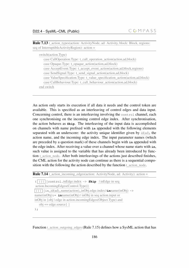
D22.4 - SysML–CML (Public)
Rule 7.13 t_action_types(action: ActivityNode, ad: Activity, block: Block, regions:seq of InterruptibleActivityRegion): action =
switch(action.Type)case CallOperation.Type: t_call_operation_action(action,ad,block)case Opaque.Type: t_opaque_action(action,ad,block)case AcceptEvent.Type: t_accept_event_action(action,ad,block,regions)case SendSignal.Type: t_send_signal_action(action,ad,block)case ValueSpecification.Type: t_value_specification_action(action,ad,block)case CallBehaviour.Type: t_call_behaviour_action(action,ad,block)
end switch
An action only starts its execution if all data it needs and the control token areavailable. This is specified as an interleaving of control edges and data input.Concerning control, there is an interleaving involving the control channel, eachone synchronising on the incoming control edge index. After synchronisation,the action behaves as Skip. The interleaving of the input data is accomplishedon channels with name prefixed with in appended with the following elementsseparated with an underscore: the activity unique identifier given by id(ad), theaction name, and the incoming edge index. The input parameter names (whichare preceded by a question mark) of these channels begin with in appended withthe edge index. After receiving a value over a channel whose name starts with in,such value is assigned to the variable that has already been introduced by func-tion t_action_node. After both interleavings of the actions just described finishes,the CML action for the activity node can continue as there is a sequential compo-sition with the following the action described by the function t_action_node.
Rule 7.14 t_action_incoming_edges(action: ActivityNode, ad: Activity): action =
( ||| {control.inEdge.index -> Skip | inEdge in seqaction.IncomingEdges(Control.Type)}||| {in_id(ad)_name(action)_inObj.edge.index?inname(inObj) ->
name(inObj):= inname(inObj) | inObj in seq action.input orinObj in {obj | edge in action.incomingEdges(Object.Type) and
obj == edge.source} });
Function t_action_outgoing_edges (Rule 7.15) defines how a SysML action that has
186
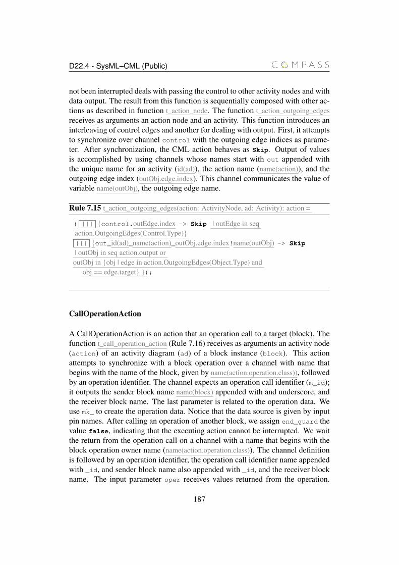
D22.4 - SysML–CML (Public)
not been interrupted deals with passing the control to other activity nodes and withdata output. The result from this function is sequentially composed with other ac-tions as described in function t_action_node. The function t_action_outgoing_edgesreceives as arguments an action node and an activity. This function introduces aninterleaving of control edges and another for dealing with output. First, it attemptsto synchronize over channel control with the outgoing edge indices as parame-ter. After synchronization, the CML action behaves as Skip. Output of valuesis accomplished by using channels whose names start with out appended withthe unique name for an activity (id(ad)), the action name (name(action)), and theoutgoing edge index (outObj.edge.index). This channel communicates the value ofvariable name(outObj), the outgoing edge name.
Rule 7.15 t_action_outgoing_edges(action: ActivityNode, ad: Activity): action =
( ||| {control.outEdge.index -> Skip | outEdge in seqaction.OutgoingEdges(Control.Type)}||| {out_id(ad)_name(action)_outObj.edge.index!name(outObj) -> Skip
| outObj in seq action.output oroutObj in {obj | edge in action.OutgoingEdges(Object.Type) and
obj == edge.target} });
CallOperationAction
A CallOperationAction is an action that an operation call to a target (block). Thefunction t_call_operation_action (Rule 7.16) receives as arguments an activity node(action) of an activity diagram (ad) of a block instance (block). This actionattempts to synchronize with a block operation over a channel with name thatbegins with the name of the block, given by name(action.operation.class)), followedby an operation identifier. The channel expects an operation call identifier (m_id);it outputs the sender block name name(block) appended with and underscore, andthe receiver block name. The last parameter is related to the operation data. Weuse mk_ to create the operation data. Notice that the data source is given by inputpin names. After calling an operation of another block, we assign end_guard thevalue false, indicating that the executing action cannot be interrupted. We waitthe return from the operation call on a channel with a name that begins with theblock operation owner name (name(action.operation.class)). The channel definitionis followed by an operation identifier, the operation call identifier name appendedwith _id, and sender block name also appended with _id, and the receiver blockname. The input parameter oper receives values returned from the operation.
187
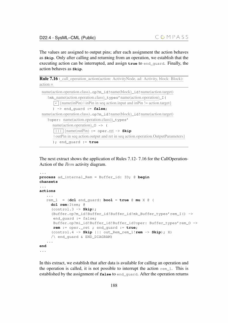
D22.4 - SysML–CML (Public)
The values are assigned to output pins; after each assignment the action behavesas Skip. Only after calling and returning from an operation, we establish that theexecuting action can be interrupted, and assign true to end_guard. Finally, theaction behaves as Skip.
Rule 7.16 t_call_operation_action(action: ActivityNode, ad: Activity, block: Block):action =
name(action.operation.class).op?m_id!name(block)_id!name(action.target)!mk_name(action.operation.class)_types’name(action.operation)_I(
, {name(inPin) | inPin in seq action.input and inPin != action.target}) -> end_guard := false;
name(action.operation.class).op?m_id!name(block)_id!name(action.target)?oper: name(action.operation.class))_types’
name(action.operation)_O -> (
||| {name(outPin) := oper.ret -> Skip
| outPin in seq action.output and ret in seq action.operation.OutputParameters}); end_guard := true
The next extract shows the application of Rules 7.12- 7.16 for the CallOperation-Action of the Rem activity diagram.
...process ad_internal_Rem = Buffer_id: ID; @ beginchansets...actions
...rem_1 = (dcl end_guard: bool = true @ mu X @ (dcl rem:Item; @(control.3 -> Skip);(Buffer.op?m_id!Buffer_id!Buffer_id!mk_Buffer_types’rem_I() ->end_guard := false;Buffer.op?mi_id!Buffer_id!Buffer_id?oper: Buffer_types’rem_O ->rem := oper._ret ; end_guard := true;
(control.4 -> Skip ||| out_Rem_rem_1!rem -> Skip); X)/\ end_guard & END_DIAGRAM)
...end...
In this extract, we establish that after data is available for calling an operation andthe operation is called, it is not possible to interrupt the action rem_1. This isestablished by the assignment of false to end_guard. After the operation returns
188
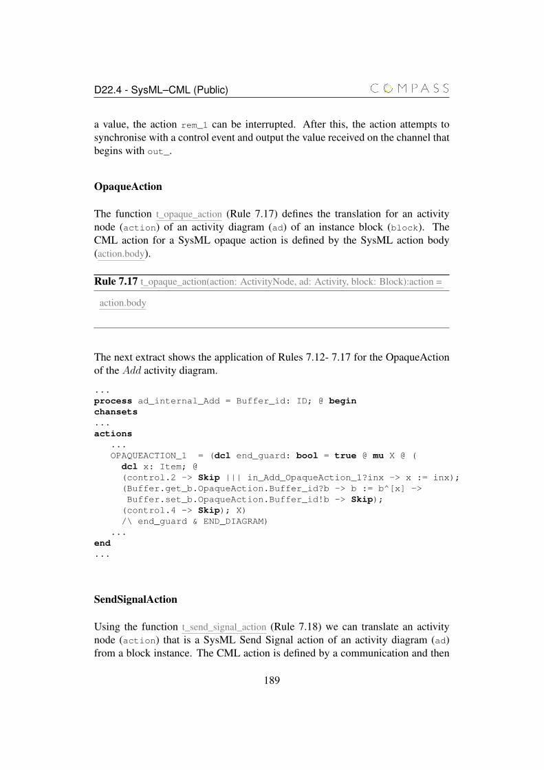
D22.4 - SysML–CML (Public)
a value, the action rem_1 can be interrupted. After this, the action attempts tosynchronise with a control event and output the value received on the channel thatbegins with out_.
OpaqueAction
The function t_opaque_action (Rule 7.17) defines the translation for an activitynode (action) of an activity diagram (ad) of an instance block (block). TheCML action for a SysML opaque action is defined by the SysML action body(action.body).
Rule 7.17 t_opaque_action(action: ActivityNode, ad: Activity, block: Block):action =
action.body
The next extract shows the application of Rules 7.12- 7.17 for the OpaqueActionof the Add activity diagram.
...process ad_internal_Add = Buffer_id: ID; @ beginchansets...actions
...OPAQUEACTION_1 = (dcl end_guard: bool = true @ mu X @ (
dcl x: Item; @(control.2 -> Skip ||| in_Add_OpaqueAction_1?inx -> x := inx);(Buffer.get_b.OpaqueAction.Buffer_id?b -> b := b^[x] ->Buffer.set_b.OpaqueAction.Buffer_id!b -> Skip);
(control.4 -> Skip); X)/\ end_guard & END_DIAGRAM)
...end...
SendSignalAction
Using the function t_send_signal_action (Rule 7.18) we can translate an activitynode (action) that is a SysML Send Signal action of an activity diagram (ad)from a block instance. The CML action is defined by a communication and then
189
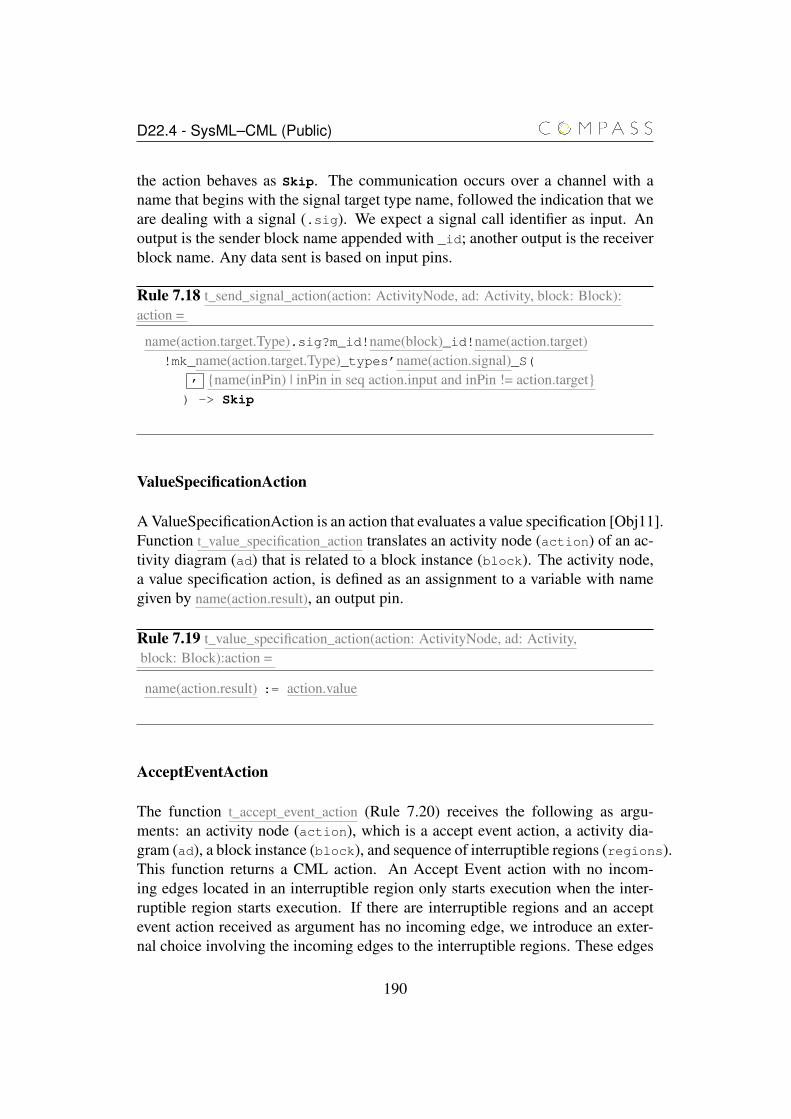
D22.4 - SysML–CML (Public)
the action behaves as Skip. The communication occurs over a channel with aname that begins with the signal target type name, followed the indication that weare dealing with a signal (.sig). We expect a signal call identifier as input. Anoutput is the sender block name appended with _id; another output is the receiverblock name. Any data sent is based on input pins.
Rule 7.18 t_send_signal_action(action: ActivityNode, ad: Activity, block: Block):action =
name(action.target.Type).sig?m_id!name(block)_id!name(action.target)!mk_name(action.target.Type)_types’name(action.signal)_S(
, {name(inPin) | inPin in seq action.input and inPin != action.target}) -> Skip
ValueSpecificationAction
A ValueSpecificationAction is an action that evaluates a value specification [Obj11].Function t_value_specification_action translates an activity node (action) of an ac-tivity diagram (ad) that is related to a block instance (block). The activity node,a value specification action, is defined as an assignment to a variable with namegiven by name(action.result), an output pin.
Rule 7.19 t_value_specification_action(action: ActivityNode, ad: Activity,block: Block):action =
name(action.result) := action.value
AcceptEventAction
The function t_accept_event_action (Rule 7.20) receives the following as argu-ments: an activity node (action), which is a accept event action, a activity dia-gram (ad), a block instance (block), and sequence of interruptible regions (regions).This function returns a CML action. An Accept Event action with no incom-ing edges located in an interruptible region only starts execution when the inter-ruptible region starts execution. If there are interruptible regions and an acceptevent action received as argument has no incoming edge, we introduce an exter-nal choice involving the incoming edges to the interruptible regions. These edges
190
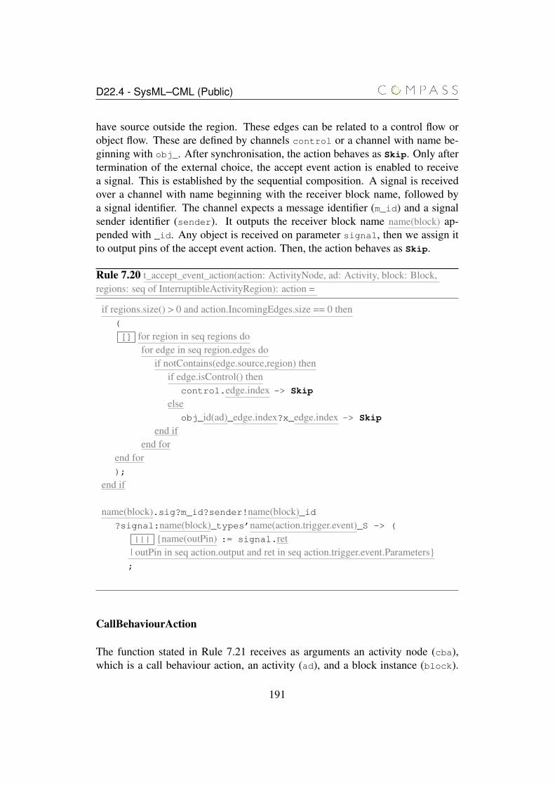
D22.4 - SysML–CML (Public)
have source outside the region. These edges can be related to a control flow orobject flow. These are defined by channels control or a channel with name be-ginning with obj_. After synchronisation, the action behaves as Skip. Only aftertermination of the external choice, the accept event action is enabled to receivea signal. This is established by the sequential composition. A signal is receivedover a channel with name beginning with the receiver block name, followed bya signal identifier. The channel expects a message identifier (m_id) and a signalsender identifier (sender). It outputs the receiver block name name(block) ap-pended with _id. Any object is received on parameter signal, then we assign itto output pins of the accept event action. Then, the action behaves as Skip.
Rule 7.20 t_accept_event_action(action: ActivityNode, ad: Activity, block: Block,regions: seq of InterruptibleActivityRegion): action =
if regions.size() > 0 and action.IncomingEdges.size == 0 then(
[] for region in seq regions dofor edge in seq region.edges do
if notContains(edge.source,region) thenif edge.isControl() then
control.edge.index -> Skip
elseobj_id(ad)_edge.index?x_edge.index -> Skip
end ifend for
end for);
end if
name(block).sig?m_id?sender!name(block)_id?signal:name(block)_types’name(action.trigger.event)_S -> (
||| {name(outPin) := signal.ret| outPin in seq action.output and ret in seq action.trigger.event.Parameters};
CallBehaviourAction
The function stated in Rule 7.21 receives as arguments an activity node (cba),which is a call behaviour action, an activity (ad), and a block instance (block).
191
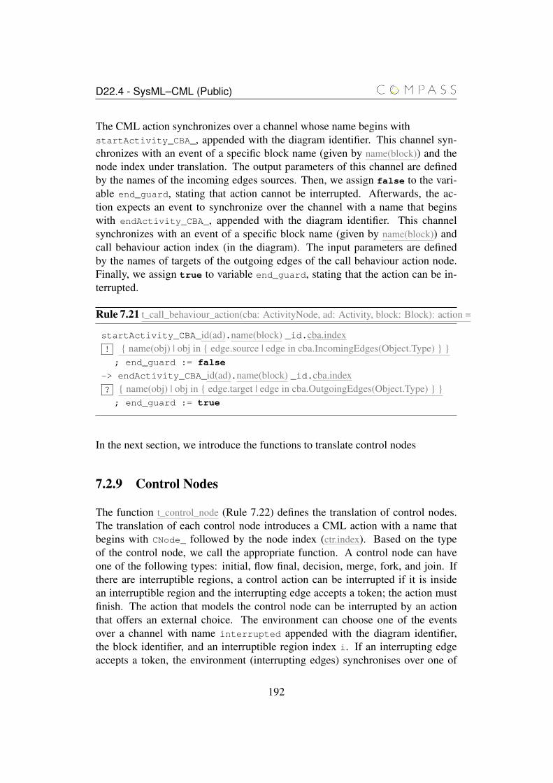
D22.4 - SysML–CML (Public)
The CML action synchronizes over a channel whose name begins withstartActivity_CBA_, appended with the diagram identifier. This channel syn-chronizes with an event of a specific block name (given by name(block)) and thenode index under translation. The output parameters of this channel are definedby the names of the incoming edges sources. Then, we assign false to the vari-able end_guard, stating that action cannot be interrupted. Afterwards, the ac-tion expects an event to synchronize over the channel with a name that beginswith endActivity_CBA_, appended with the diagram identifier. This channelsynchronizes with an event of a specific block name (given by name(block)) andcall behaviour action index (in the diagram). The input parameters are definedby the names of targets of the outgoing edges of the call behaviour action node.Finally, we assign true to variable end_guard, stating that the action can be in-terrupted.
Rule 7.21 t_call_behaviour_action(cba: ActivityNode, ad: Activity, block: Block): action =
startActivity_CBA_id(ad).name(block) _id.cba.index! { name(obj) | obj in { edge.source | edge in cba.IncomingEdges(Object.Type) } }; end_guard := false
-> endActivity_CBA_id(ad).name(block) _id.cba.index? { name(obj) | obj in { edge.target | edge in cba.OutgoingEdges(Object.Type) } }; end_guard := true
In the next section, we introduce the functions to translate control nodes
7.2.9 Control Nodes
The function t_control_node (Rule 7.22) defines the translation of control nodes.The translation of each control node introduces a CML action with a name thatbegins with CNode_ followed by the node index (ctr.index). Based on the typeof the control node, we call the appropriate function. A control node can haveone of the following types: initial, flow final, decision, merge, fork, and join. Ifthere are interruptible regions, a control action can be interrupted if it is insidean interruptible region and the interrupting edge accepts a token; the action mustfinish. The action that models the control node can be interrupted by an actionthat offers an external choice. The environment can choose one of the eventsover a channel with name interrupted appended with the diagram identifier,the block identifier, and an interruptible region index i. If an interrupting edgeaccepts a token, the environment (interrupting edges) synchronises over one of
192
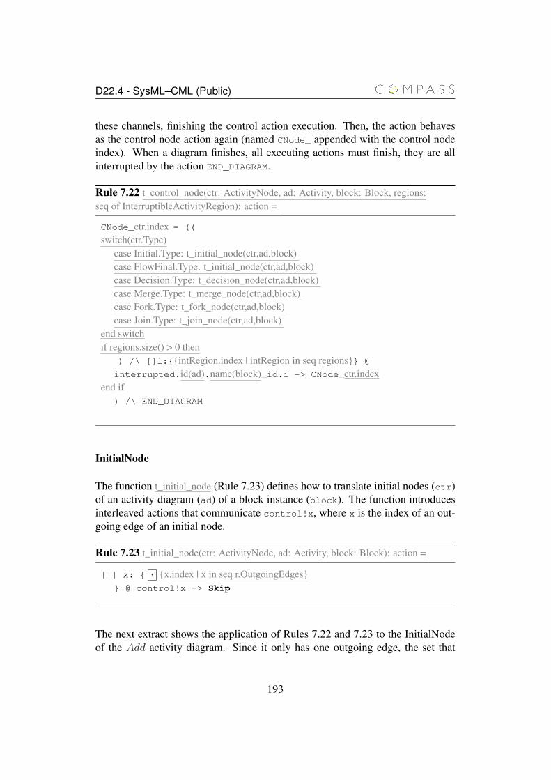
D22.4 - SysML–CML (Public)
these channels, finishing the control action execution. Then, the action behavesas the control node action again (named CNode_ appended with the control nodeindex). When a diagram finishes, all executing actions must finish, they are allinterrupted by the action END_DIAGRAM.
Rule 7.22 t_control_node(ctr: ActivityNode, ad: Activity, block: Block, regions:seq of InterruptibleActivityRegion): action =
CNode_ctr.index = ((
switch(ctr.Type)case Initial.Type: t_initial_node(ctr,ad,block)case FlowFinal.Type: t_initial_node(ctr,ad,block)case Decision.Type: t_decision_node(ctr,ad,block)case Merge.Type: t_merge_node(ctr,ad,block)case Fork.Type: t_fork_node(ctr,ad,block)case Join.Type: t_join_node(ctr,ad,block)
end switchif regions.size() > 0 then
) /\ []i:{{intRegion.index | intRegion in seq regions}} @
interrupted.id(ad).name(block)_id.i -> CNode_ctr.indexend if
) /\ END_DIAGRAM
InitialNode
The function t_initial_node (Rule 7.23) defines how to translate initial nodes (ctr)of an activity diagram (ad) of a block instance (block). The function introducesinterleaved actions that communicate control!x, where x is the index of an out-going edge of an initial node.
Rule 7.23 t_initial_node(ctr: ActivityNode, ad: Activity, block: Block): action =
||| x: { , {x.index | x in seq r.OutgoingEdges}} @ control!x -> Skip
The next extract shows the application of Rules 7.22 and 7.23 to the InitialNodeof the Add activity diagram. Since it only has one outgoing edge, the set that
193
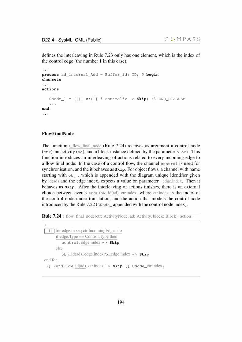
D22.4 - SysML–CML (Public)
defines the interleaving in Rule 7.23 only has one element, which is the index ofthe control edge (the number 1 in this case).
...process ad_internal_Add = Buffer_id: ID; @ beginchansets...actions
...CNode_1 = (||| x:{1} @ control!x -> Skip) /\ END_DIAGRAM...
end...
FlowFinalNode
The function t_flow_final_node (Rule 7.24) receives as argument a control node(ctr), an activity (ad), and a block instance defined by the parameter block. Thisfunction introduces an interleaving of actions related to every incoming edge toa flow final node. In the case of a control flow, the channel control is used forsynchronisation, and the it behaves as Skip. For object flows, a channel with namestarting with obj_, which is appended with the diagram unique identifier givenby id(ad) and the edge index, expects a value on parameter _edge.index. Then itbehaves as Skip. After the interleaving of actions finishes, there is an externalchoice between events endFlow.id(ad).ctr.index, where ctr.index is the index ofthe control node under translation, and the action that models the control nodeintroduced by the Rule 7.22 (CNode_ appended with the control node index).
Rule 7.24 t_flow_final_node(ctr: ActivityNode, ad: Activity, block: Block): action =
(
||| for edge in seq ctr.IncomingEdges doif edge.Type == Control.Type then
control.edge.index -> Skip
elseobj_id(ad)_edge.index?x_edge.index -> Skip
end for); (endFlow.id(ad).ctr.index -> Skip [] CNode_ctr.index)
194
D22.4 - SysML–CML (Public)
DecisionNode
The function t_decision_node (Rule 7.25) establishes how to translate a decisionnode. If the incoming edge is concerned with control, then the action expectssynchronisation over channel control with the control incoming edge index asparameter. Notice that this rule uses the auxiliary rule t_statecopy(block, ctr) thatcreates a local copy of the block instance state. A non deterministic if statementis introduced with the guard of each guarded command defined by the guards ofthe outgoing edges from the decision node. This is followed by an event overchannel control with the decision node outgoing edge index. In the case of anobject flow, a non deterministic if statement is introduced with one guarded com-mand for each guard of the outgoing edges. When a guard is satisfied, the objectreceived via the channel that represents the incoming edge of the decision node iscommunicated through a channel named obj_ appended with the following: thediagram unique identifier (provided by id(ad)), an underscore, the outgoing edgeindex outEdge.index.
195
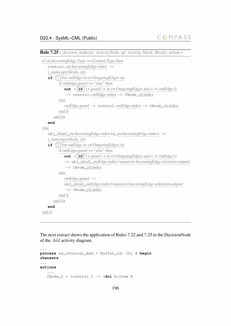
D22.4 - SysML–CML (Public)
Rule 7.25 t_decision_node(ctr: ActivityNode, ad: Activity, block: Block): action =
if ctr.IncomingEdge.Type == Control.Type thencontrol.ctr.IncomingEdge.index ->
t_statecopy(block, ctr)if | for outEdge in ctr.OutgoingEdges do
if outEdge.guard == "else" thennot ( or {x.guard | x in ctr.OutgoingEdges and x != outEdge})-> control.outEdge.index -> CNode_ctr.index
elseoutEdge.guard -> control.outEdge.index -> CNode_ctr.index
end ifend for
end
elseobj_id(ad)_ctr.IncomingEdge.index?x_ctr.IncomingEdge.index) ->t_statecopy(block, ctr)if | for outEdge in ctr.OutgoingEdges do
if outEdge.guard == "else" thennot ( or {x.guard | x in ctr.OutgoingEdges and x != outEdge})-> obj_id(ad)_outEdge.index!name(ctr.IncomingEdge.selection.output)-> CNode_ctr.index
elseoutEdge.guard ->
obj_id(ad)_outEdge.index!name(ctr.IncomingEdge.selection.output)-> CNode_ctr.index
end ifend for
end
end if
The next extract shows the application of Rules 7.22 and 7.25 to the DecisionNodeof the Add activity diagram.
...process ad_internal_Add = Buffer_id: ID; @ beginchansets...actions
...CNode_2 = (control.1 -> (dcl b:Item @
196
D22.4 - SysML–CML (Public)
Buffer.get_b.CNode2.Buffer_id?b ->if b.size() >= 5 -> control.3 -> CNode_2
| b.size < 5 -> control.2 -> CNode_2end)) /\ END_DIAGRAM
...end...
The action CNode_2 models the decision node that appears in Add. Depending onthe buffer size, this action synchronises on the event control.3 or control.2.Then, the action behaves as CNode_2 again. This action can be interrupted if theactivity Add finishes.
MergeNode
A merge node is translated by the function t_merge_node (Rule 7.26). It receivesas arguments an activity node (ctr), which is a merge node, an activity (ad),and block instance (block). The incoming edges of a merge node are all eitherof object flows or all of control flows. If the outgoing edge of a merge node isa control flow (Control.Type), then the action that models the merge node syn-chronises with one of the incoming control edges from the set of indexes given by{x.index | x in ctr.IncomingEdges}. Then the action communicates over the controlchannel the outgoing edge index. Finally, the action behaves again as the (merge)control node. In the case of object flow, the action offers to the environment thepossibility of communication over channels with name starting with obj_ for eachincoming edge. The whole channel name is defined by the concatenation of obj_with id(ad)_, and the incoming edge index (inEdge.index). The input parameteris called x. After communication of a value recorded in x, such value is givenas output over a channel whose name starts with obj_ appended with the withid(ad)_, and the outgoing edge index (ctr.OutgoingEdge.index). After output, theaction behaves again as the merge control node action just introduced.
197
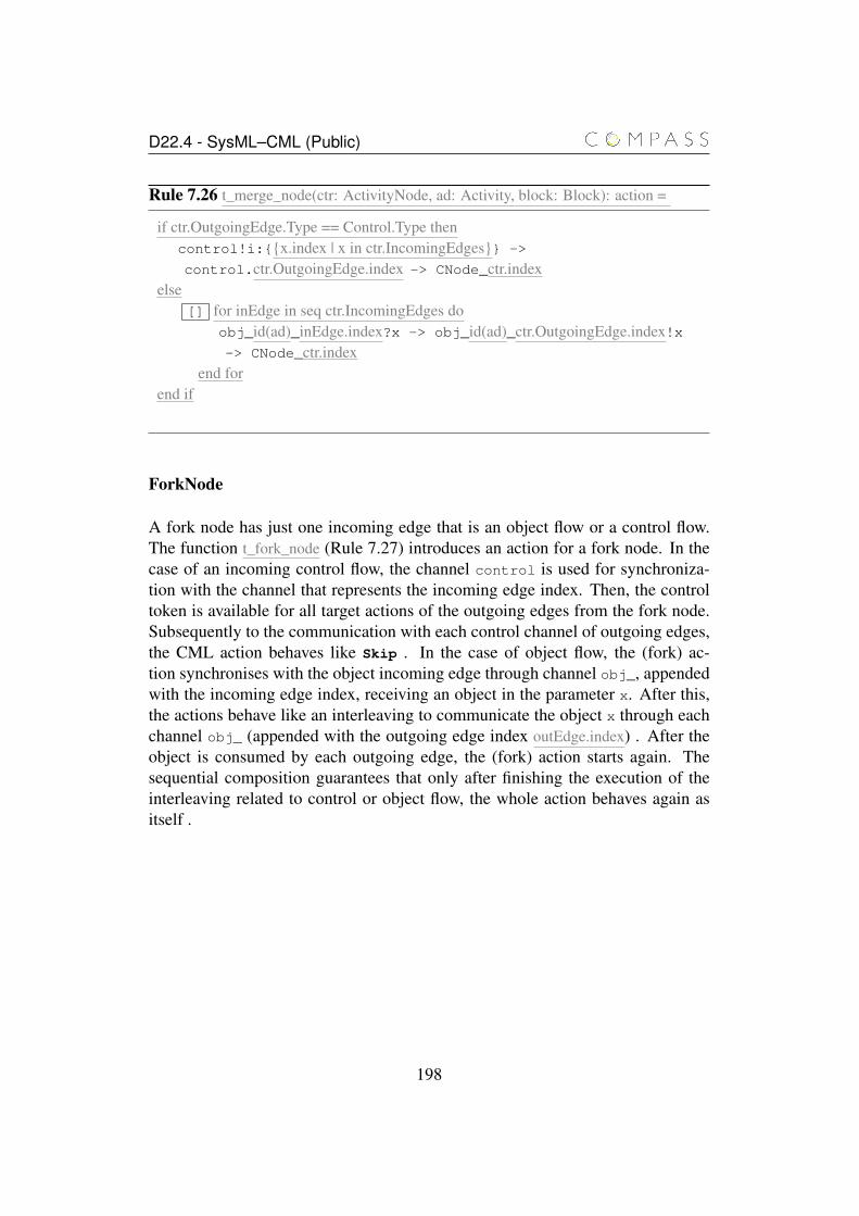
D22.4 - SysML–CML (Public)
Rule 7.26 t_merge_node(ctr: ActivityNode, ad: Activity, block: Block): action =
if ctr.OutgoingEdge.Type == Control.Type thencontrol!i:{{x.index | x in ctr.IncomingEdges}} ->
control.ctr.OutgoingEdge.index -> CNode_ctr.indexelse
[] for inEdge in seq ctr.IncomingEdges doobj_id(ad)_inEdge.index?x -> obj_id(ad)_ctr.OutgoingEdge.index!x-> CNode_ctr.index
end forend if
ForkNode
A fork node has just one incoming edge that is an object flow or a control flow.The function t_fork_node (Rule 7.27) introduces an action for a fork node. In thecase of an incoming control flow, the channel control is used for synchroniza-tion with the channel that represents the incoming edge index. Then, the controltoken is available for all target actions of the outgoing edges from the fork node.Subsequently to the communication with each control channel of outgoing edges,the CML action behaves like Skip . In the case of object flow, the (fork) ac-tion synchronises with the object incoming edge through channel obj_, appendedwith the incoming edge index, receiving an object in the parameter x. After this,the actions behave like an interleaving to communicate the object x through eachchannel obj_ (appended with the outgoing edge index outEdge.index) . After theobject is consumed by each outgoing edge, the (fork) action starts again. Thesequential composition guarantees that only after finishing the execution of theinterleaving related to control or object flow, the whole action behaves again asitself .
198
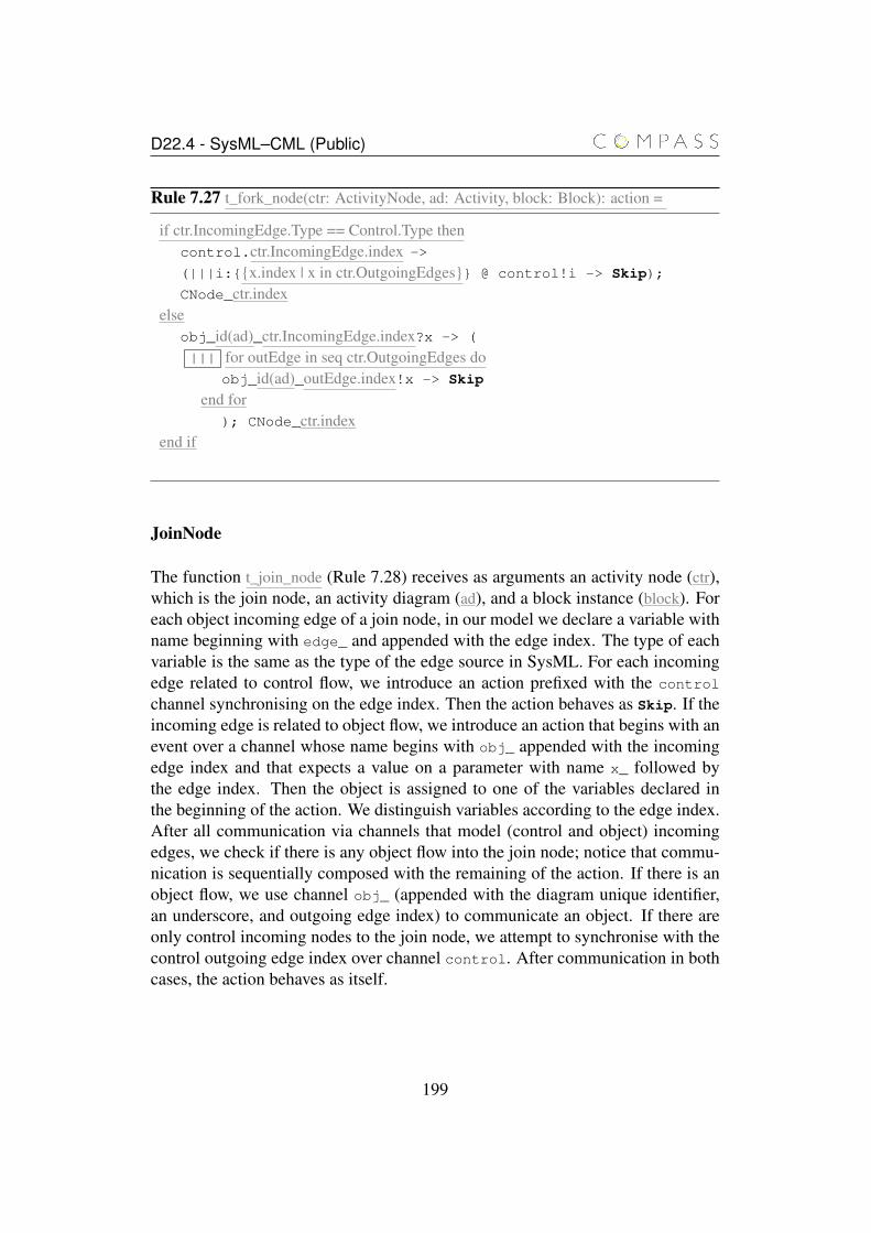
D22.4 - SysML–CML (Public)
Rule 7.27 t_fork_node(ctr: ActivityNode, ad: Activity, block: Block): action =
if ctr.IncomingEdge.Type == Control.Type thencontrol.ctr.IncomingEdge.index ->
(|||i:{{x.index | x in ctr.OutgoingEdges}} @ control!i -> Skip);
CNode_ctr.indexelse
obj_id(ad)_ctr.IncomingEdge.index?x -> (
||| for outEdge in seq ctr.OutgoingEdges doobj_id(ad)_outEdge.index!x -> Skip
end for); CNode_ctr.index
end if
JoinNode
The function t_join_node (Rule 7.28) receives as arguments an activity node (ctr),which is the join node, an activity diagram (ad), and a block instance (block). Foreach object incoming edge of a join node, in our model we declare a variable withname beginning with edge_ and appended with the edge index. The type of eachvariable is the same as the type of the edge source in SysML. For each incomingedge related to control flow, we introduce an action prefixed with the control
channel synchronising on the edge index. Then the action behaves as Skip. If theincoming edge is related to object flow, we introduce an action that begins with anevent over a channel whose name begins with obj_ appended with the incomingedge index and that expects a value on a parameter with name x_ followed bythe edge index. Then the object is assigned to one of the variables declared inthe beginning of the action. We distinguish variables according to the edge index.After all communication via channels that model (control and object) incomingedges, we check if there is any object flow into the join node; notice that commu-nication is sequentially composed with the remaining of the action. If there is anobject flow, we use channel obj_ (appended with the diagram unique identifier,an underscore, and outgoing edge index) to communicate an object. If there areonly control incoming nodes to the join node, we attempt to synchronise with thecontrol outgoing edge index over channel control. After communication in bothcases, the action behaves as itself.
199
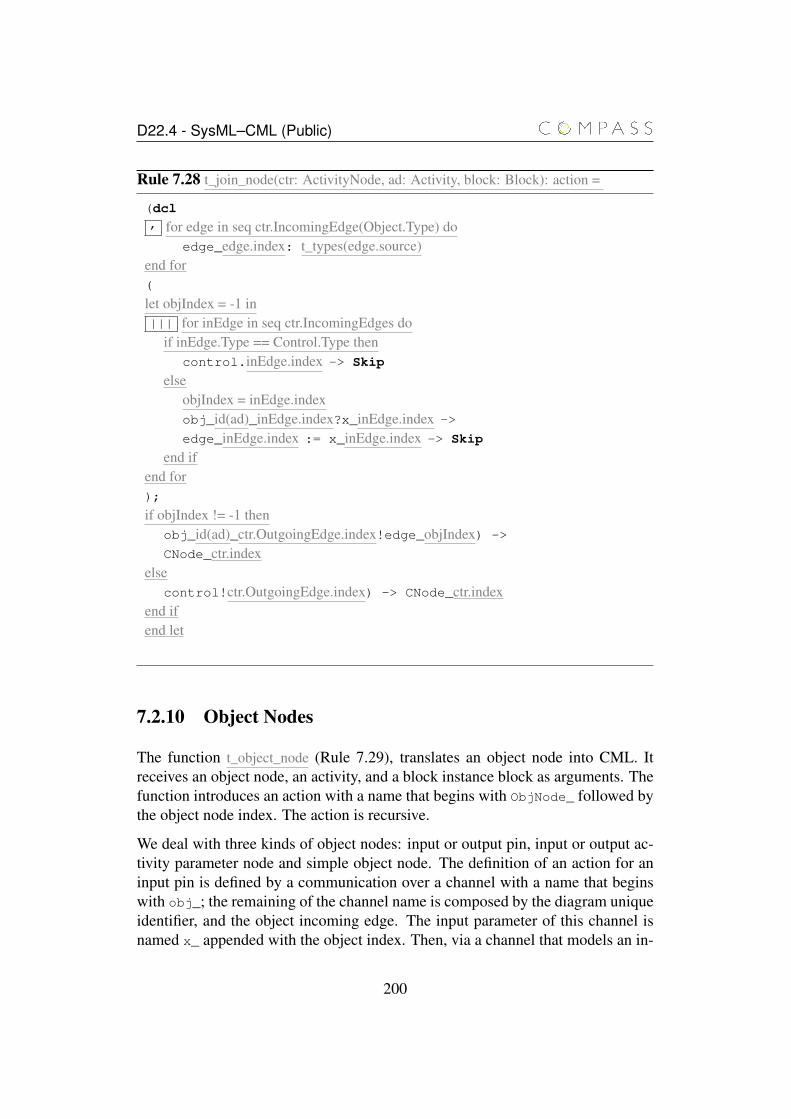
D22.4 - SysML–CML (Public)
Rule 7.28 t_join_node(ctr: ActivityNode, ad: Activity, block: Block): action =
(dcl, for edge in seq ctr.IncomingEdge(Object.Type) do
edge_edge.index: t_types(edge.source)end for(
let objIndex = -1 in||| for inEdge in seq ctr.IncomingEdges do
if inEdge.Type == Control.Type thencontrol.inEdge.index -> Skip
elseobjIndex = inEdge.indexobj_id(ad)_inEdge.index?x_inEdge.index ->
edge_inEdge.index := x_inEdge.index -> Skip
end ifend for);
if objIndex != -1 thenobj_id(ad)_ctr.OutgoingEdge.index!edge_objIndex) ->
CNode_ctr.indexelse
control!ctr.OutgoingEdge.index) -> CNode_ctr.indexend ifend let
7.2.10 Object Nodes
The function t_object_node (Rule 7.29), translates an object node into CML. Itreceives an object node, an activity, and a block instance block as arguments. Thefunction introduces an action with a name that begins with ObjNode_ followed bythe object node index. The action is recursive.
We deal with three kinds of object nodes: input or output pin, input or output ac-tivity parameter node and simple object node. The definition of an action for aninput pin is defined by a communication over a channel with a name that beginswith obj_; the remaining of the channel name is composed by the diagram uniqueidentifier, and the object incoming edge. The input parameter of this channel isnamed x_ appended with the object index. Then, via a channel that models an in-
200
D22.4 - SysML–CML (Public)
put pin we communicate x_ appended with the object index. After the occurrenceof synchronisation events, we have a recursive call.
In the case of an output pin, the sequence of events begins with a communicationvia the channel that models the output pin, followed by a communication through achannel that models an object node. After the occurrence of both synchronisationevents, we have a recursive call.
In the case of activity parameter nodes, which serve as output for an activity (theyhave no outgoing edges but have at least one incoming edge), we define an ex-ternal choice over channels that model the incoming edge to the parameter node.The channels names begin with obj_ appended with a diagram unique identi-fier (id(ad)), an underscore, the incoming edge index(obj.IncomingEdge.index), anunderscore, the incoming object index (obj.index), and the output parameter x_
appended with the object index. Then, the action assigns the value received aftercommunication to a variable with the same name as the object. After assignment,the action behaves as an external choice between an event (endFlow) and a recur-sive call.
When the activity parameter is an input, we define an interleaving of actions; eachone defined by a communication followed by Skip. If the object node is not apin, or an activity parameter node, the model is defined by an input parameter x_,appended with the object index, of the channel with name beginning with obj_
appended with a diagram unique identifier (id(ad)), an underscore, and the incom-ing edge index (obj.IncomingEdge.index). Then, the action attempts to output thevalue received through a channel with a name similar to the one used for input;the value in x_, appended with the object index is used, is used for output.
If an object node is inside an interruptible region its execution finishes if a token isaccepted in an interrupting edge. The action that models this case can choose oneof the events over a channel with name interrupted appended with the diagramid, the block id (name(block)_id), and an interruptible region index i. If an in-terrupting edge accepts a token, the environment defined by interruptible regionsactions will synchronise over one of these channels, finishing the object node ac-tion execution. Then, the action will behave as the object node action again. Whena model of an activity finishes, all executing object node actions must finish, theyare all interrupted by the action END_DIAGRAM.
201
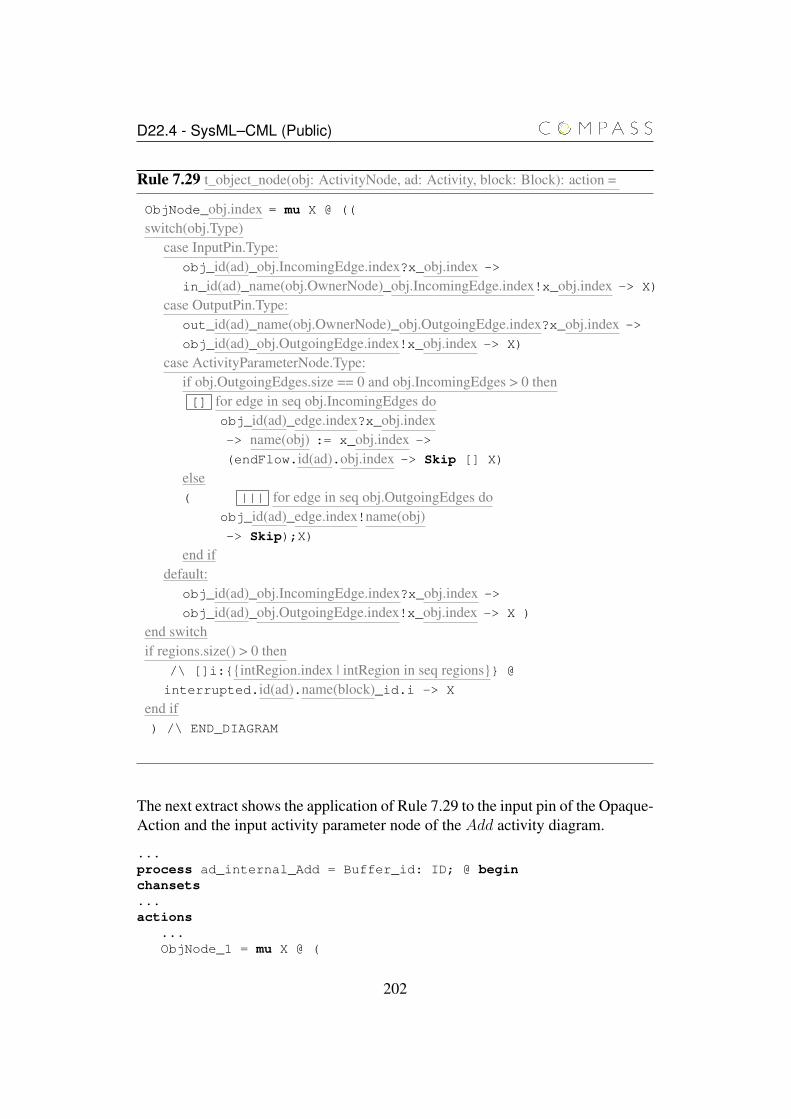
D22.4 - SysML–CML (Public)
Rule 7.29 t_object_node(obj: ActivityNode, ad: Activity, block: Block): action =
ObjNode_obj.index = mu X @ ((
switch(obj.Type)case InputPin.Type:
obj_id(ad)_obj.IncomingEdge.index?x_obj.index ->
in_id(ad)_name(obj.OwnerNode)_obj.IncomingEdge.index!x_obj.index -> X)
case OutputPin.Type:out_id(ad)_name(obj.OwnerNode)_obj.OutgoingEdge.index?x_obj.index ->
obj_id(ad)_obj.OutgoingEdge.index!x_obj.index -> X)
case ActivityParameterNode.Type:if obj.OutgoingEdges.size == 0 and obj.IncomingEdges > 0 then[] for edge in seq obj.IncomingEdges do
obj_id(ad)_edge.index?x_obj.index-> name(obj) := x_obj.index ->
(endFlow.id(ad).obj.index -> Skip [] X)
else( ||| for edge in seq obj.OutgoingEdges do
obj_id(ad)_edge.index!name(obj)-> Skip);X)
end ifdefault:
obj_id(ad)_obj.IncomingEdge.index?x_obj.index ->
obj_id(ad)_obj.OutgoingEdge.index!x_obj.index -> X )
end switchif regions.size() > 0 then
/\ []i:{{intRegion.index | intRegion in seq regions}} @
interrupted.id(ad).name(block)_id.i -> X
end if) /\ END_DIAGRAM
The next extract shows the application of Rule 7.29 to the input pin of the Opaque-Action and the input activity parameter node of the Add activity diagram.
...process ad_internal_Add = Buffer_id: ID; @ beginchansets...actions
...ObjNode_1 = mu X @ (
202
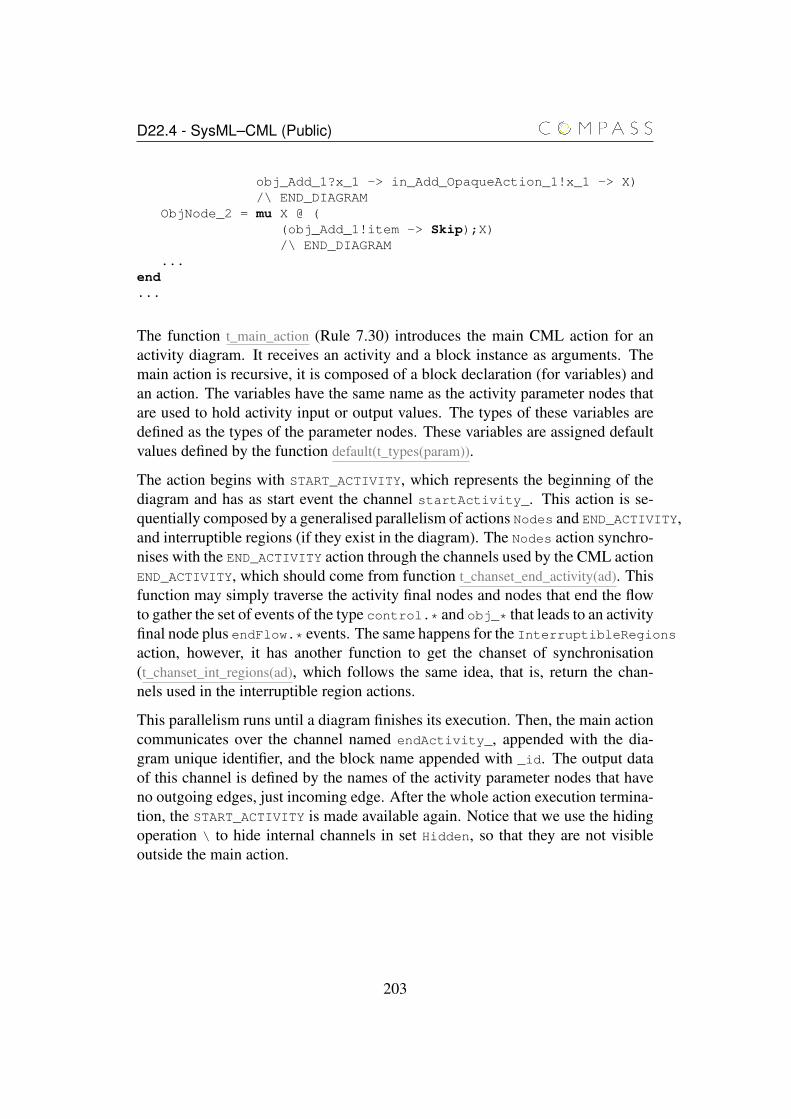
D22.4 - SysML–CML (Public)
obj_Add_1?x_1 -> in_Add_OpaqueAction_1!x_1 -> X)/\ END_DIAGRAM
ObjNode_2 = mu X @ ((obj_Add_1!item -> Skip);X)/\ END_DIAGRAM
...end...
The function t_main_action (Rule 7.30) introduces the main CML action for anactivity diagram. It receives an activity and a block instance as arguments. Themain action is recursive, it is composed of a block declaration (for variables) andan action. The variables have the same name as the activity parameter nodes thatare used to hold activity input or output values. The types of these variables aredefined as the types of the parameter nodes. These variables are assigned defaultvalues defined by the function default(t_types(param)).
The action begins with START_ACTIVITY, which represents the beginning of thediagram and has as start event the channel startActivity_. This action is se-quentially composed by a generalised parallelism of actions Nodes and END_ACTIVITY,and interruptible regions (if they exist in the diagram). The Nodes action synchro-nises with the END_ACTIVITY action through the channels used by the CML actionEND_ACTIVITY, which should come from function t_chanset_end_activity(ad). Thisfunction may simply traverse the activity final nodes and nodes that end the flowto gather the set of events of the type control.* and obj_* that leads to an activityfinal node plus endFlow.* events. The same happens for the InterruptibleRegionsaction, however, it has another function to get the chanset of synchronisation(t_chanset_int_regions(ad), which follows the same idea, that is, return the chan-nels used in the interruptible region actions.
This parallelism runs until a diagram finishes its execution. Then, the main actioncommunicates over the channel named endActivity_, appended with the dia-gram unique identifier, and the block name appended with _id. The output dataof this channel is defined by the names of the activity parameter nodes that haveno outgoing edges, just incoming edge. After the whole action execution termina-tion, the START_ACTIVITY is made available again. Notice that we use the hidingoperation \ to hide internal channels in set Hidden, so that they are not visibleoutside the main action.
203
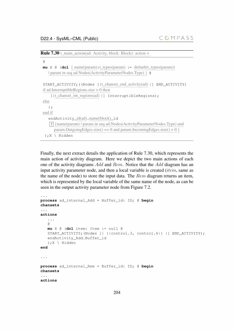
D22.4 - SysML–CML (Public)
Rule 7.30 t_main_action(ad: Activity, block: Block): action =
@
mu X @ (dcl { name(param):t_types(param) := default(t_types(param))| param in seq ad.Nodes(ActivityParameterNodes.Type) } @
START_ACTIVITY;((Nodes [|t_chanset_end_activity(ad) |] END_ACTIVITY)
if ad.InterruptibleRegions.size > 0 then[|t_chanset_int_regions(ad) |] InterruptibleRegions);
else);
end ifendActivity_id(ad).name(block)_id
! {name(param) | param in seq ad.Nodes(ActivityParameterNodes.Type) andparam.OutgoingEdges.size() == 0 and param.IncomingEdges.size() > 0 }
);X \ Hidden
Finally, the next extract details the application of Rule 7.30, which represents themain action of activity diagram. Here we depict the two main actions of eachone of the activity diagrams Add and Rem. Notice that the Add diagram has aninput activity parameter node, and then a local variable is created (item, same asthe name of the node) to store the input data. The Rem diagram returns an item,which is represented by the local variable of the same name of the node, as can beseen in the output activity parameter node from Figure 7.2.
...process ad_internal_Add = Buffer_id: ID; @ beginchansets...actions
...@mu X @ (dcl item: Item := null @START_ACTIVITY;(Nodes [| {|control.3, control.4|} |] END_ACTIVITY);endActivity_Add.Buffer_id);X \ Hidden
end
...
process ad_internal_Rem = Buffer_id: ID; @ beginchansets...actions
204
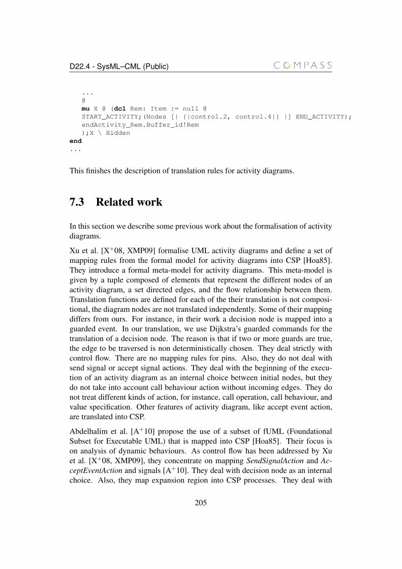
D22.4 - SysML–CML (Public)
...@mu X @ (dcl Rem: Item := null @START_ACTIVITY;(Nodes [| {|control.2, control.4|} |] END_ACTIVITY);endActivity_Rem.Buffer_id!Rem);X \ Hidden
end...
This finishes the description of translation rules for activity diagrams.
7.3 Related work
In this section we describe some previous work about the formalisation of activitydiagrams.
Xu et al. [X+08, XMP09] formalise UML activity diagrams and define a set ofmapping rules from the formal model for activity diagrams into CSP [Hoa85].They introduce a formal meta-model for activity diagrams. This meta-model isgiven by a tuple composed of elements that represent the different nodes of anactivity diagram, a set directed edges, and the flow relationship between them.Translation functions are defined for each of the their translation is not composi-tional, the diagram nodes are not translated independently. Some of their mappingdiffers from ours. For instance, in their work a decision node is mapped into aguarded event. In our translation, we use Dijkstra’s guarded commands for thetranslation of a decision node. The reason is that if two or more guards are true,the edge to be traversed is non deterministically chosen. They deal strictly withcontrol flow. There are no mapping rules for pins. Also, they do not deal withsend signal or accept signal actions. They deal with the beginning of the execu-tion of an activity diagram as an internal choice between initial nodes, but theydo not take into account call behaviour action without incoming edges. They donot treat different kinds of action, for instance, call operation, call behaviour, andvalue specification. Other features of activity diagram, like accept event action,are translated into CSP.
Abdelhalim et al. [A+10] propose the use of a subset of fUML (FoundationalSubset for Executable UML) that is mapped into CSP [Hoa85]. Their focus ison analysis of dynamic behaviours. As control flow has been addressed by Xuet al. [X+08, XMP09], they concentrate on mapping SendSignalAction and Ac-ceptEventAction and signals [A+10]. They deal with decision node as an internalchoice. Also, they map expansion region into CSP processes. They deal with
205
D22.4 - SysML–CML (Public)
signals by means of an asynchronous buffer, whereas in our translation we usea one-place synchronised buffer that could receive data from an asynchronousbuffer. Their communication model allows storing of signals.
Bisztray, Ehrig, and Heckel [BEH07] define translation rules that relate edges inan activity diagram to a process in CSP [Hoa85]. They do not deal with objectnodes or object flow, just with the translation of control flow. They translate a joinnode separately from the fork node. In other words, they have distinct translationrules for these control nodes. A consequence of that is that a synchronisationevent appears only in the process that reach the join node, but not in the paralleloperator that is introduced in the fork node. Also, the translation of the join noderesults in processes that are not similar: only one will behave as the process afterthe join, all the others will terminate in Skip. In our case, the reason for dealingwith fork-join pairs is that if we treat them separately when we translate a joinnode it is necessary to change the CML part that corresponds to the fork node thathas been translated before the join node.
Table 7.1 presents a comparison of the coverage of our formalisation with re-lated work. The left column contains the features we formalised. The X indi-cates that the feature is covered by related work (column), whereas × indicatesit is not. We cover the following features: Call Behaviour Action (CBA), In-terruptible Region (IRg), Call Operation Action (COA), Opaque Action (OpA),Accept Event Action (AEv ), Send Signal Action (SSA), Value Specification Ac-tion (VSA), Initial Node (IN), Flow Final Node (FF), Decision Node (DN), MergeNode (MN), Fork Node (FN), Join Node (JN), Activity Final Node (AFN), ObjectNode (ObjN), Control Flow (CtrF), Object Flow (ObjF), and Activity ParameterNode (APN).
206
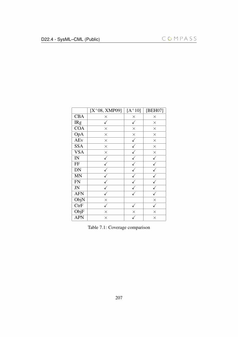
D22.4 - SysML–CML (Public)
[X+08, XMP09] [A+10] [BEH07]CBA × × ×IRg X X ×COA × × ×OpA × × ×AEv × X ×SSA × X ×VSA × X ×IN X X XFF X X XDN X X XMN X X XFN X X XJN X X XAFN X X XObjN × ×CtrF X X XObjF × × ×APN × X ×
Table 7.1: Coverage comparison
207
Chapter 8
Conclusions
In this chapter, we discuss and summarise our main contributions, and set anagenda for future work in task T2.2.2.
8.1 Summary
In this document we report on the formal link between SysML and CML by meansof a denotational semantics. We have identified a restricted yet comprehensive setof diagrams and features that allows us to provide a semantics in CML.
We have formalised the semantics of blocks (as specified by block definition andinternal block diagrams), state machine, sequence and activity diagrams. The se-mantics of blocks is central to the integration of both structural and behaviouralaspects of complex SysML models into a single CML model. Whilst our seman-tics does not cover the totality of SysML, it provides a comprehensive treatmentof the main types of diagrams that affect the behaviour of the system.
The semantics of blocks is given with respect to the underlying model of the blockstructure obtained by pre-processing the block definition and internal block dia-grams. At the level of diagrams, different aspects of a block can be specified indifferent diagrams; the required pre-processing simply merges information that isspread across a number of diagrams to build an integral view of the elements of themodel, and is carried out by the modelling tool when creating the model definedby the diagrams. Based on this integrated view, we propose translation rules forsimple and composite blocks, as well as for ports. Blocks and ports are translatedinto CML processes, these processes may use other processes that model any as-sociated state machines and activity diagrams. In the case of a composite block,
208
D22.4 - SysML–CML (Public)
the process is defined in terms of the process that model the parts of the block.Associations between blocks (and ports) are modelled through alphabetised com-position, where appropriate channel sets are defined to allow the communicationbetween the blocks. In line with our guidelines, we support signals and oper-ations, provided and required interfaces, and state machines as block behaviourspecifications.
Our treatment of state machine diagrams covers a large number of elements,namely, simple, orthogonal and non-orthogonal states, regions, junctions, com-pletion and non-completion transitions, join and fork pseudostates and final pseu-dostates.
Regarding sequence diagrams, although the main constructs have been translated,some other elements must be dealt in the future. The synchronization mecha-nism used for the message exchange can only be applied to the semantics of syn-chronous calls. Although we know some strategies to represent asynchronism inthese cases, their adequacy will be further investigated. The remaining combinedfragments not yet translated must be analysed to understand which ones are in-teresting for System of Systems modelling. Duration and time constraints alsomay have possible translation allowing strict restrictions on time. The use of stateinvariants may be one lead to integrate sequence and state machine diagrams. An-other interesting possibility is to verify consistency of the relationships depictedin sequence diagram according to the ones modelled in structural diagrams andin the others behavioural diagrams. Finally, the use of allocations must be furtherinvestigated to check another possibilities for integration.
The translation rules for activity diagrams cover action nodes, object nodes, con-trol nodes (decision, merge, fork, join, flow final, and activity final). Also, thereare translations rules for Accept Event Action, and Send Signal Action. Commu-nication is treated as synchronous, although Accept Event Action, for instance,involves asynchronous communication. We have translated object flows betweenobject node also using synchronous communication.
To the best of our knowledge, no other work has formalised a semantics of SysMLor UML models with the same level of coverage as the one presented in this re-port.
We observe main areas where development needs to be focused: validation of themodels of SysML diagrams, and refinement in SysML. In the next sections, webriefly discuss each of them, identify the main challenges and discuss how thesechallenges may be overcome.
209
D22.4 - SysML–CML (Public)
8.2 Validation
The models obtained through the translation strategies presented in this reporthave only been validated by manual translation, simulation and analysis of smallexamples. In order to simulate the models, the CML specifications are trans-lated into CSP, and simulated and analysed using CSP tools: ProBE [For98] andFDR2 [For99]. The translation from CML to CSP is carried out manually, and wedo not believe a general enough translation strategy between the two notations canbe devised. Moreover, it can be difficult to interpret analysis and simulation resultof the CSP models with respect to the CML models. This preliminary validationwas made against our understanding of how the model should behave.
The next step in validating our models is to apply our translation rules in a moresystematic and automatic fashion to support the generation of more complex dia-grams. To this end, a prototype translation tool is being developed by Atego basedon the translation rules for blocks, state machines and sequence diagrams. Fur-thermore, once the CML tools support simulation and analysis, we will be ableto directly validate our semantics by both verifying properties of the models, andcomparing simulation results of the CML models against the results of alternativesimulation tools.
8.3 Refinement in SysML
Since CML is a refinement language, and our semantics of SysML is based onCML, it is only natural to think of refinement at the level of SysML diagrams. Infact, refinement has a two-fold role in our work:
1. Refinement provides the means for correct-by-construction simplificationsof our models. The rules proposed in this document aim at providing acompositional and extendable semantics for SysML models, additionallywe have avoided the inclusion of optimisations in our translation rules, forthese reasons the models tend to be large and rely heavily on parallelism,which can lead to an increase in the cost of analysis as well as simulation. Tocircumvent these issues, refinement strategies can be devised to simplify andoptimise the CML models, whilst preserving the original semantics. Thisapproach presents an advantage over the optimisation of translation as suchoptimisation is necessarily manual and error prone, whilst models obtainedthrough a refinement-based optimisation are correct by construction.
2. Refinement as a means for transforming SysML models. Particularly in the
210
D22.4 - SysML–CML (Public)
field of software engineering, model transformation have been thoroughlyinvestigated. However, these transformations are usually cast in a purelysyntactic form, and semantic correctness is not formally verified. Refine-ment may be the key for supporting the development of formally verifiedmodel transformations.
211
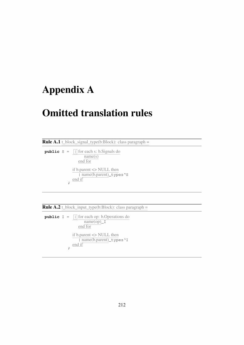
Appendix A
Omitted translation rules
Rule A.1 t_block_signal_type(b:Block): class paragraph =
public S = | for each s: b.Signals doname(s)
end for
if b.parent <> NULL then| name(b.parent)_types‘S
end if;
Rule A.2 t_block_input_type(b:Block): class paragraph =
public I = | for each op: b.Operations doname(op)_I
end for
if b.parent <> NULL then| name(b.parent)_types‘I
end if;
212
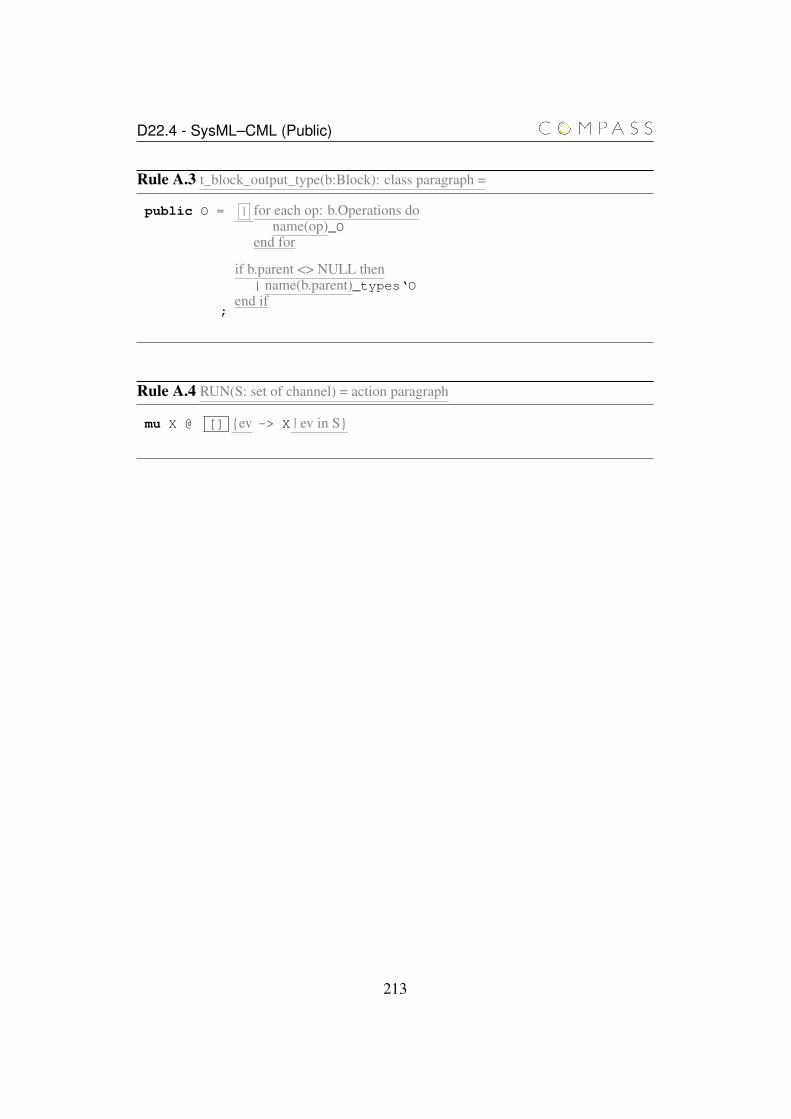
D22.4 - SysML–CML (Public)
Rule A.3 t_block_output_type(b:Block): class paragraph =
public O = | for each op: b.Operations doname(op)_O
end for
if b.parent <> NULL then| name(b.parent)_types‘O
end if;
Rule A.4 RUN(S: set of channel) = action paragraph
mu X @ [] {ev -> X | ev in S}
213
Bibliography
[A+10] I. Abdelhalim et al. Formal verification of Tokeneer behavioursmodelled in fUML using CSP|. In Proceedings of the 12th inter-national conference on Formal engineering methods and softwareengineering, ICFEM’10, pages 371–387, Berlin, Heidelberg, 2010.Springer-Verlag.
[Are00] D. B. Aredo. Semantics of uml statecharts in pvs. Technical report,Department of Informatics, University of Oslo, 2000.
[BAL00] E. Börger, A., and S. Larosa. Modeling the dynamics of uml statemachines. In Proceedings of the International Workshop on Ab-stract State Machines, Theory and Applications, LNCS. Springer,2000.
[BDM02] S. Bernardi, S. Donatelli, and J. Merseguer. From uml sequencediagrams and statecharts to analysable petri net models. In Pro-ceedings of the 3rd International Workshop on Software and Per-formance. ACM Press, 2002.
[BEH07] D. Bisztray, K. Ehrig, and R. Heckel. Case study: UML to CSPtransformation. Technical report, University of Leicester, UK,2007.
[BvW98] Ralph-Johan Back and Joakim von Wright. Refinement Calculus:A Systematic Introduction. Texts in Computer Science. Springer-Verlag New York, Inc., Secaucus, NJ, USA, 1998.
[CD05] M. L. Crane and J. Dingel. On the uml state machines: Categoriza-tion and comparison. Technical Report 2005-501, Queen’s Univer-sity, 2005.
[CHS00] K. Compton, J. K. Huggins, and W. Shen. A semantic modelfor the state machine in the unified modelling language. In Dy-
214
D22.4 - SysML–CML (Public)
namic Behaviour in UML Models: Semantic Questions. Ludwig-Maximilians-Universität München, 2000.
[CKF05] Alessandra Cavarra and Juliana Küster-Filipe. Combining se-quence diagrams and ocl for liveness. Electron. Notes Theor. Com-put. Sci., 115:19–38, January 2005.
[CML+12] Joey W. Coleman, Anders Kaels Malmos, Peter Gorm Larsen, JanPeleska, Ralph Hains, Zoe Andrews, Richard Payne, Simon Foster,Alvaro Miyazawa, Cristiano Bertolini, and André Didier. COM-PASS Tool Vision for a System of Systems Collaborative Develop-ment Environment. In Proceedings of the 7th International Confer-ence on System of System Engineering, IEEE SoSE 2012, volume 6of IEEE Systems Journal, July 2012.
[CMmuM05] María Victoria Cengarle, Technische Universität München, andLudwig maximilians-universität München. A.: Operational seman-tics of uml 2.0 interactions. Technical report, 2005.
[DD10] Li Dan and Li Danning. Towards a formal behavioral semanticsfor UML interactions. In Proceedings of the 2010 Third Interna-tional Symposium on Information Science and Engineering, ISISE’10, pages 213–218, Washington, DC, USA, 2010. IEEE ComputerSociety.
[Dij75] Edsger W. Dijkstra. Guarded commands, nondeterminacy and for-mal derivation of programs. Commun. ACM, 18(8):453–457, 1975.
[DT10] Song Ding and Sheng-Qun Tang. An approach for formal repre-sentation of sysml block diagram with description logic shioq(d).In Proceedings of the 2nd International Conference on Industrialand Information Systems, volume 2, pages 259–261, 2010.
[EFM+05] Christoph Eichner, Hans Fleischhack, Roland Meyer, UlrikSchrimpf, and Christian Stehno. Compositional semantics forUML 2.0 sequence diagrams using Petri Nets. In Andreas Prinz,Rick Reed, and Jeanne Reed, editors, SDL Forum, volume 3530of Lecture Notes in Computer Science, pages 133–148. Springer,2005.
[FL09] John Fitzgerald and Peter Gorm Larsen. Modelling Systems: Prac-tical Tools and Techniques in Software Development. CambridgeUniversity Press, 2nd edition, 2009.
215
D22.4 - SysML–CML (Public)
[FMS11] S. Friedenthal, A. Moore, and R. Steiner. A Practical Guide toSysML: The Systems Modeling Language. Morgan Kaufmann Pub-lishers Inc., San Francisco, CA, USA, 2011. 2nd edition.
[For98] Formal Systems (Europe) Ltd. Process Behaviour Explorer -ProBE User Manual, 1998.
[For99] Formal Systems (Europe) Ltd. FDR: User Manual and Tutorial,version 2.28, 1999.
[GB11] Henson Graves and Yvonne Bijan. Using formal methods withsysml in aerospace design and engineering. Annals of Mathematicsand Artificial Intelligence, pages 1–50, 2011.
[Gra09] Henson Graves. Integrating sysml and owl. In Proceedings ofOWL: Experiences and Directions, 2009.
[HHM+07] Margaret H. Hamilton, William R. Hackler, Copyright Margaret,H. Hamilton, William R. Hackler Published, and Used Incose Per-mission. A formal universal systems semantics for sysml, 2007.
[HHRS05] Oystein Haugen, Knut Eilif Husa, Ragnhild Kobro Runde, andKetil Stolen. Stairs towards formal design with sequence diagrams.Software and System Modeling, 4(4):355–367, 2005.
[HJ98] Tony Hoare and Hi Jifeng. Unifying Theories of Programming.Prentice Hall, April 1998.
[HNH+12] Jon Holt, Claus Ballegaard Nielsen, Finn Overgaard Hansen, Al-varo Miyazawa, Richard Payne, Juliano Iyoda, and Marcio Corne-lio. Initial Report on SoS Architectural Models. Technical ReportD22.1, COMPASS Deliverable, March 2012.
[Hoa85] C. A. R. Hoare. Communicating and Sequential Processes. Pren-tice Hall, 1985.
[Hol09] Jon Holt. A Pragmatic Guide to Business Process Modelling.British Computer Society, Swinton, UK, UK, 2nd edition, 2009.
[HP08] J. Holt and S. Perry. SysML for Systems Engineering. IET, 2008.
[HPHH12] Jon Holt, Simon Perry, Finn Overgaard Hansen, and Stefan Haller-stede. Report on Guidelines for SoS Requirements. Technical Re-port D21.1, COMPASS Deliverable, May 2012.
[HPM11] J. Holt, S. Perry, and Brownsword M. Model-Based RequirementsEngineering. IET, 2011.
216
D22.4 - SysML–CML (Public)
[JEJ04] Y. Jin, R. Esser, and J. W. Janneck. A method for describing thesyntax and semantics of uml statecharts. Software and SystemsModelling, 3(2):150–163, 2004.
[KW07] Alexander Knapp and Jochen Wuttke. Model checking of UML2.0 interactions. In Models in Software Engineering, volume 4364of LNCS, pages 42–51. Springer Berlin Heidelberg, 2007.
[LLJ04] Xiaoshan Li, Zhiming Liu, and He Jifeng. A formal seman-tics of UML sequence diagram. In Proceedings of the 2004Australian Software Engineering Conference, ASWEC ’04, pages168–, Washington, DC, USA, 2004. IEEE Computer Society.
[LMM99] Diego Latella, Istvan Majzik, and Mieke Massink. Towards a for-mal operational semantics of UML Statechart diagrams. In Pro-ceedings of the IFIP TC6/WG6.1 Third International Conferenceon Formal Methods for Open Object-Based Distributed Systems(FMOODS), pages 465–, Deventer, The Netherlands, The Nether-lands, 1999. Kluwer, B.V.
[LP99] Johan Lilius and Ivn Porres Paltor. The semantics of UML StateMachines. Technical report, Turku Centre for Computer Science,1999.
[Lun07] Mass Soldal Lund. Operational analysis of sequence diagramspecifications. Ph.D. Thesis, University of Oslo, 2007.
[MNB04] S. Meng, Z. Naixiao, and L. S. Barbosa. On the semantics andrefinement of uml statecharts: a coalgebraic view. In Proceedingsof the 2nd International Conference on Software Engineering andFormal Methods. IEEE Computer Society, 2004.
[MW11] Zoltán Micskei and Hélène Waeselynck. The many meanings ofuml 2 sequence diagrams: a survey. Softw. Syst. Model., 10(4):489–514, October 2011.
[NB03] Muan Yong Ng and Michael Butler. Towards formalizing UMLState Diagrams in CSP. In Antonio Cerone and Peter Lindsay,editors, 1st IEEE International Conference on Software Engineer-ing and Formal Methods, pages 138–147. IEEE Computer Society,2003. Event Dates: 25-26 September 2003.
[Obj10a] Object Management Group. OMG Systems Modeling Language(OMG SysMLTM ). Technical report, Object Management Group,2010. OMG Document Number: formal/2010-06-02.
217
D22.4 - SysML–CML (Public)
[Obj10b] Object Management Group. OMG Unified Modeling Language(OMG UML), superstructure, version 2.3. Technical report, OMG,2010.
[Obj11] Object Management Group. OMG Unified Modeling Language(OMG UML), superstructure, version 2.4.1. Technical report,OMG, 2011.
[OMG05] OMG. MOF QVT Final Adopted Specification. OMG, June 2005.
[RSM05] Rodrigo Ramos, Augusto Sampaio, and Alexandre Mota. A seman-tics for uml-rt active classes via mapping into circus. In SOCIETYFOR COMPUTER SIMULATION, pages 99–114. Springer, 2005.
[RW05] Holger Rasch and Heike Wehrheim. Checking the validity of sce-narios in UML models. In Proceedings of the 7th IFIP WG 6.1 in-ternational conference on Formal Methods for Open Object-BasedDistributed Systems, FMOODS’05, pages 67–82, Berlin, Heidel-berg, 2005. Springer-Verlag.
[Sto04] Harald Storrle. Trace semantics of interactions in uml 2.0 abstract,2004.
[SVN08] Hui Shen, Aliya Virani, and Jianwei Niu. Formalize uml 2 se-quence diagrams. In Proceedings of the 2008 11th IEEE High As-surance Systems Engineering Symposium, HASE ’08, pages 437–440, Washington, DC, USA, 2008. IEEE Computer Society.
[WCC+12] Jim Woodcock, Ana Cavalcanti, Joey Coleman, André Didier, Pe-ter Gorm Larsen, Alvaro Miyazawa, and Marcel Oliveira. CMLDefinition 0. Technical Report D23.1, COMPASS Deliverable,June 2012.
[WCF+12] J. Woodcock, A. Cavalcanti, J. Fitzgerald, P. Larsen, A. Miyazawa,and S. Perry. Features of CML: a Formal Modelling Languagefor Systems of Systems. In Proceedings of the 7th InternationalConference on System of System Engineering, volume 6 of IEEESystems Journal. IEEE, July 2012.
[Wha10] M. W. Whalen. A parametric structural operational semantics forstateflow, uml statecharts, and rhapsody. Technical Report 2010-1,University of Minnesota Software Engineering Center, 200 UnionSt., Minneapolis, MN 55455, August 2010.
[X+08] D. Xu et al. Towards Formalizing UML Activity Diagrams in CSP.In Proceedings of the 2008 International Symposium on Computer
218
D22.4 - SysML–CML (Public)
Science and Computational Technology - Volume 02, ISCSCT ’08,pages 450–453, Washington, DC, USA, 2008. IEEE Computer So-ciety.
[XMP09] D. Xu, H. Miao, and N. Philbert. Model Checking UML ActivityDiagrams in FDR. ACIS International Conference on Computerand Information Science, pages 1035–1040, 2009.
219