Final Report Nordic Built Component Reuse -...
85
Fig. 1 - Spiro Wall Final Report / Nordic Built Component Reuse Project title / Nordic Built Component Reuse Project identification / Journ. no. 64013-0580, NBCR_final_report.pdf Funding programme / Nordic Built Project managing company / Tegnestuen Vandkunsten A/S Krudtløbsvej 14, DK-1439 København K Contact / Søren Nielsen, project manager / [email protected] Project partners / Genbyg AS External partners (grants from Nordic Built NO and Formas SE) / Asplan Viak AS, Hjellness Consult AS, Malmö Tekniska Högskola CVR / 2550 7886 Date / 10.11.2016
Transcript of Final Report Nordic Built Component Reuse -...
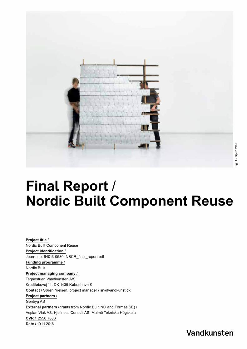
Fig.
1 -
Spi
ro W
all
Final Report / Nordic Built Component Reuse
Project title / Nordic Built Component Reuse Project identification / Journ. no. 64013-0580, NBCR_final_report.pdfFunding programme / Nordic BuiltProject managing company / Tegnestuen Vandkunsten A/S Krudtløbsvej 14, DK-1439 København K Contact / Søren Nielsen, project manager / [email protected] partners / Genbyg AS External partners (grants from Nordic Built NO and Formas SE) / Asplan Viak AS, Hjellness Consult AS, Malmö Tekniska HögskolaCVR / 2550 7886Date / 10.11.2016

2 Nordic Built Component Reuse
Final report
Project title / Nordic Built Component Reuse Editor / Vandkunsten ArchitectsImages / Finished shots of prototypes by Kirstine Autzen, other images by the team or as credited
3
46
14
36
48
61626365
66
Content Project detailsSummaryEnglishDanskExecutive SummaryIntroduction
ResultsBrick conceptsConcrete conceptsGlass conceptsMetal conceptsSoft flooring conceptsWood concepts
LCAConcrete bricks/claddingCladding using roof tilesGlazed window facadeInterior wall from reused wooden floorsSpiro Wall / Facade cladding from metal ventilation ducts
DiscussionEvaluation of resultsUtilization of resultsChallenges for implementationEvolving of the projectDisseminationFuture developmentProject conclusionLiterature
Appendix
InterviewsDissemination
Charts for material lifecyclesConcrete bricks/claddingCladding using roof tilesGlazed window facadeInterior wall from reused wooden floorsSpiro Wall / Facade cladding from metal ventilation ducts
Content

3Nordic Built Component Reuse
Final report
SummaryEnglish summaryMaterial waste is the ‘dark side’ of renovation in construction and discarded materials and components potentially represent a triple capital related to economy, energy, and culture. The project explores, by devising and constructing 20 full-scale prototypes, new practices for high-level reuse of dismantled building components and materials at all product stages from sourcing to disassembly. New commissions for products and methods confirm the commercial potential; LCAs confirm the assumption of environmental benefits of reuse; and the interest in prototypes and open-source dissemination of results will hopefully inspire the construction sector and users for further cultural development and implementation.
Danish Summary / Dansk versionByggeaffald er den mørke side af bygningsrenovering og udskiftede materialer og komponenter repræsenterer potentielt en trefoldig værdi i form af økonomi, energi og kultur. Projektet udforsker, ved design og opførelse af 20 fuldskala prototyper, ny praksis for genanvendelse af byggematerialer på højt niveau og i alle komponenternes stadier fra nedrivning til ny produkters adskillelse. Ny kommissioner for produkter og systemer bekræfter konceptets kommercielle potentiale, LCAer bekræfter formodningen om miljømæssige fordele ved genanvendelse, og den brede interesse i de bygge prototyper, samt open-source formidling vil forhåbentlig inspirere byggeindustrien og påvirke brugere til at implementere tanker og systemer fra projektet.
Fig.
1+2
/ Im
ages
from
a d
emol
ition
in C
open
hage
n

4 Nordic Built Component Reuse
Final report
Executive SummaryThe Nordic Built Component Reuse project explores, by means of 1:1 mock-up prototypes, new practices for reuse of dismantled building components and materials at all product stages - sourcing, rehabilitation, design integration, construction and marketing - resulting in visions of new ways to organize, tender and trade reused building components.
ChallengeThe project addresses material waste - the ‘dark side’ of renovation in construction. The demolishing practice in the Nordic countries today is highly efficient in terms of separating construction debris and minimizing landfill. However, discarded resources represent a triple capital related to economy, energy, and culture. The challenge is to find new ways to access this value and implement the Circular Economy in construction.
Project aimsIt is the premise of this project that future construction practice must enable resource-preserving strategies, including:1. Repurposing building waste from demolishing, dismantling, and refurbishment.2. Reversible construction principles known as Design for Disassembly (DfD).
The ultimate ambition of the NBCR-project is to generate competition within the field through and apply an open-source approach rather than certified and commercialized methods. By establishing a strong architectural identity as well as profitable business for recycled components, we intend to inspire and assist the development of the circular economy in the Nordic countries. Furthermore we have intended to improve methods and quality of environmental evaluations of reused materials through the use of flow charts and expanded LCA work.
Methods The transformational journey from ‘waste materials’ at hand to valuable new components was investigated through an array of methods. First, we investigated the current market status through interviews with industry experts. Based on specific properties and availability of large material groups, the team then used the Sfc-system to categorize waste components and map their potential applications. Then the team selected and applied Design for Disassembly principles and iterative, architectural design methods to develop multiple novel architectural concepts for facades and interior wall systems. from scrap materials groups of brick, concrete, soft flooring, steel, end wood
We have designed and prototyped new component systems from discarded building materials. The prototypes were to be beautiful, implement completely reversible construction principles, be sellable, and possible to manufacture through processes that are effective in cost and energy.
20 Concepts were selected to be prototyped in full-scale following criteria including: material categories; feasibility, material amounts, and design aesthetics. For five cases, all procedures were timed and documented, and full LCA-analyses carried out. Along with the physical objects, this allowed us to assess concepts in terms of economy, energy, and culture.A second group of material concepts were developed further and illustrated.
1:1 work has formed the core work and led to exhibitions, lectures, and publications. A second series of illustrations depict scenarios of transferred technologies and novel sourcing methods and machines that would enable increased reuse.
Executive Summary

5Nordic Built Component Reuse
Final report
From the topFig 4 — Prototypes of cut concrete slab facade.
Fig 5 — prototype of pantile facade system.
Fig 6 — prototype of rolled Spiro ducts as a facade screen.
Fig 7 — Detail of facade screen prototype from adjusted double glazed windows.
Fig 8 — Prototype of New Nordic Wall built from wooden elements.
ResultsThe physical results of the project are the 20 full-scale prototypes made from five groups of transformed materials and components. Five have formed key cases:
o Concrete Principles for cutting and assembling concrete slabs displayed aesthetics of weathering and exposing concrete for façade panels. Due to safety and logistics, these prototypes were cast mock-ups and not cut from waste. Heavy equipment is costly and energy consuming. This results in poor commercial assessment and the LCA that shows that more energy is spent in direct reuse than in using new components.
o Brick A new façade system for pantiles is fully designed for disassembly with a customized mounting system. Though challenged by a time consuming process and mixed availability, the tiles do weather beautifully like brickwork which adds to the cultural value of the material concept. The LCA is good for this concept which is in use in a building project for a client of Genbyg.
o Metal A new façade system uses rolled metal ventilation tubes and utilizes existing mounting systems for slate. The aesthetics of the metal surface appears culturally well-known and the concept has a strong story - two parameters that add to a strong assessment of the concept. Furthermore the alteration of tubes to sheets is simple which results in a positive LCA.
o Windows For a façade screen with iron profiles and reused glazed windows the windows get same dimensions and an elegant aesthetics by cutting sides off the wooden frame of double glazed windows. Using simple wedges to fasten the frames on the iron profile, the new façade screen is fully reversible with
beautiful detailing and a positive LCA comparison.
o Wood New Nordic Wall is the wood-based version of the exposed brick interior wall dubbed ‘New Yorker Wall’ by Nordic real estate agents. It is a double-sided building block to stack and restack for interior decorations and room divisions. The sandwich components fit together with a tongue and a groove; they have a core of standard fire doors and cladding in a variety of wooden surfaces from old floors or facades. The LCA is good.
LCAsDouble sets of comparable LCAs as well as extensive workflow charts were also conducted for key prototypes and all but the concrete concepts had strong LCAs. Prototypes have been broadly assessed for cultural and commercial value. In the commercial assessment of concepts ease of construction was compared with the cultural value for Genbyg customers. There are no clear conclusions as some beautiful concepts were assessed as poor due to embedded toxic materials, poor LCA or cost performance whereas the assessment of expensive prototypes rated high due to potential exclusivity with a market niche.
The physical results are supplemented with intellectual results in terms of deep insight and tested methods for analysis, design and assessment
The results are already in use by project partners as tools to inspire and assist clients as well as for design competitions and bids. New commissions for products and methods confirm the commercial potential and Genbyg has now established an in-house design studio and expanded their business model; LCAs confirm the assumption of environmental benefits of reuse; and the interest in prototypes and open-source dissemination of results will hopefully inspire the construction sector and users for further cultural development and implementation.
Executive Summary

6 Nordic Built Component Reuse
Final report
Project ideaThe project explores, by means of 1:1 mock-up modelling, novel practices for reuse of dismantled building components and materials at all product stages - sourcing, rehabilitation, design integration, construction and marketing - resulting in visions for new ways to organize, tender and trade reused building components. Aims are to devise and prototype new component systems from discarded building materials. The prototypes should be beautiful, implement completely reversible construction principles, be sellable, and possible to manufacture through processes that are effective in cost and energy.By establishing a strong architectural identity as well as profitable business for recycled components, the idea is to move the boundary line between waste and value and inspire and assist the development of the circular economy in the Nordic countries. Furthermore we have intended to improve methods of environmental evaluations of reused materials through the use of flow charts and LCA analyses.
RelevanceThe global interest in the Circular Economy has influenced the governmental agenda in the Nordic countries1, in EU.2 Industrial
1 I.e. The Circular Economy is a buzzword influencing legislators and businesses across the World. When the Danish government launched the 2013 resource strategy “Denmark without waste”, construction waste was named a major source of future resources which could and should be used as such. recommended in Norwegian technical building regulations (Teknisk Forskrift), §9-5 Waste: “Construction products which are suitable for reuse and recycling should be selected.” The guidance specifies further: “Designing for reuse will help ensure that a building can be disassembled so that the materials and products can be used again. Through the design, it must be displayed specific assessments regarding reuse and recycling.” (translated by author). http://dibk.no/no/BYGGEREGLER/Gjeldende-byggeregler/Veiledning-om-tekniske-krav-til byggverk/?dxp=/dxp/content/tekniskekrav/9/5/2 EU Parliament: On Resource Efficiency: Moving Towards a Circular Economy (2014/2208(INI)) Draft Report (presently in consultation phase) 24.03.2015, i.e. p. 9: 2. ‘Cascading use of resources is a way of maximising resource efficiency. It entails a systematic effort to first exploit materials for higher added value products and to then use them multiple
organisations have recently embraced the agenda.3 The theme is covered in literature – mostly in intentional or theoretical terms. . The technical theory behind resource preserving is already developed to a high level4 but has never found breeding ground on the current market conditions. Business concepts like Cradle-to-Cradle (C2C)5 have been commercially successful within a narrow field of recycling, but have not managed to devise reuse solutions in practice. The C2C is carefully adapted to an industrial economy in which dismantled components are defined as waste bereft of functional or social value, but merely available as raw material for recycling.
The project addresses the ‘dark side’ of building renovation - the material waste that is the consequence of current practice. The demolishing practice in the Nordic countries today is efficient at separating construction debris and minimizing landfill6. However, in present practice, waste materials are most often broken down to the lowest level of its potential: for combustion or for recycling as secondary material. Only a very small part of demolition waste is reused in a similar function or for other purposes without extensive degradation. Consequently resources embodied in processes of manufacturing and maintenance are wasted along with potential cultural, economic, and aesthetic values. Thus demolition waste potentially represents a triple capital that it is relevant to explore.
times as resources in other product categories.’3 Danish Industry, Environmental Policy Program August 2015. Also, C2C-principles have been implemented as part of the assessment criteria in two major architectural competitions (Posthuset 2013 and Lilletorget 2015) by Entra Eiendom, one of Norway’s leading real estate companies. Posthuset 2013; http://www.arkitektur.no/nordic-builtLilletorget 2015; http://www.arkitektur.no/entra-competition14 E.g.: Thormark 1998, Crowther 2001, Durmisevic 2006, Nordby 2008, Sassi 20095 Based on the book published in 2002 by Braungart and William McDonough “ Cradle to Cradle: Remaking the Way We Make Things”6 Miljøministeriet, Miljøstyrelsen, Affaldsstatistik 2011, Notat 11.06.2013 (http://mst.dk/media/mst/Attachments/Affaldsstatistik2012.pdf)
Introduction
Introduction

7Nordic Built Component Reuse
Final report
Project aim and scopeThe aim of the project is to inspire and influence the development of a construction practice for high-level reuse that supports and enables: 1: Repurposing of dismantled components from building renovation without degradation, and2: Design for Disassembly (DfD). Construction principles that aim at future reuse of components.
The overall vision of this project is to inspire the agents of the construction sector to pursue a higher-level resource reuse that secure qualities in terms of culture, history, economy, and environment. The direct goal is to improve the foundation of business and income for the participating companies.
The most important focus of the project is high-level reuse as opposed to current utilization strategies. This project searches out the possible remaining functional and social values in the dismantled component and alternative reuse at a higher level is suggested. The project’s scope is strictly limited to building materials; it is an attempt to address the conditioning structures and workflows within the building industry and the built environment..
Project backgroundWith a strategy for reusing discarded material components; Vandkunsten won a 2012 competition for the renovation of a large Danish housing project7. Crucial challenges in regards to economy, technology, and culture, faced the implementation of the strategies as the competition brief was developed into the project currently under execution. The experience revealed that the construction industry is poorly prepared for a conversion towards a more effective and careful utilization of resources8. A widespread reluctance was found with industrial professionals as well as with the tenants. When comparing mock-ups of refurbished homes, inhabitants preferred the new and conventional material surfaces over the reused solutions; a preference partly due to a higher price of repurposed material components and in part due to a different aesthetics and tradition.
The idea for the current project was initiated here. It appeared to Vandkunsten and Genbyg that the economic, legislative and cultural structures are not yet mature for the necessary conversion and there is need for new and inspirational solutions, which manage to meet technical, environmental and cultural requirements as well as ripe business models to gear the market for the development. (Fig 9)
Team and collaboratorsThe project partners are Vandkunsten Architects (DK), Genbyg.dk (DK), Asplan Viak (NO), Malmö Högskola (SE) and Hjellnes Consult (NO).
Architecture master students have also contributed to the work. In 2014, Anna Meyer, in the fall of 2015, a group of students used NBCR as the foundation of their semester assignment “Recycling Station – design strategies for material reuse” by architecture students Lena Fedders, Amalie Brandt Opstrup og Line Tebering, Royal Danish Academy of Fine Arts, School of Architecture, Settlement Ecology and Tectonics . They worked as architectural research interns9 and had their work spaces at the office of Vandkunsten for a full semester.
The group of company experts include; Danish Waste Solutions, Diatool Aps (Diamond
7 Albertslund Syd Gårdhavehusene, renovation of 1000 low-dense residences, including proposed reuse of dismantled original flooring as interior wall cladding. Arkitekten 2014/1.8 I.e.: Ellen MacArthur Fondation: Towards the Circular Economy Vol. 1-2. Report 2012-139 Carried out as an InnoBYG initiative in September 2015-January 2016
- Figure 9 / Dismantled floorboards from renovation repurposed as wall cladding, Vandkunsten in Albertslund Syd, 2014.
Introduction

8 Nordic Built Component Reuse
Final report
Tools), Glarmester Aage Larsen (Glazier), Glasfakta: Expertise and counselling on glass, HJ Hansen: Scrap Dealer, RGS 90 A/S: Waste handling and recycling company, RoboCluster Innovationsnetværk: private-public robot-themed cluster, and Tscherning A/S, Demolition contractor
MethodsThe transformational journey from ‘waste materials’ at hand to valuable new components was investigated through an array of methods. First, we investigated the current market status through interviews with industry experts. Based on specific properties and availability of large material groups, the team then used the Sfc-system to categorize waste components and map their potential applications. Then the team selected and applied Design for Disassembly principles and iterative, architectural design methods to develop multiple novel architectural concepts for facades and interior wall systems. Materials were selected from materials groups of brick, concrete, soft flooring, steel, end wood.
20 Concepts were selected to be prototyped in full-scale following criteria including: material categories; feasibility, material amounts, and design aesthetics. For five cases, all procedures were timed and documented, and full LCA-analyses carried out. Along with the physical objects, this allowed us to assess concepts in terms of economy, energy, and culture.
A second group of material concepts were developed further and illustrated.1:1 work has formed the core work and led to exhibitions, oral dissemination as well as publications.
A second series of illustrations depict scenarios of transferred technologies and novel sourcing methods and machines that would enable increased reuse. Those are not included in this report Architectural output and methodsPrototypes were developed by creative design methods.10 Creative design can be described a generative regime of iterative series of tentative proposals oscillating between multiple instrumental and social media.11 Media and scales vary and include: o Sketching; hand drawings, 3D digital modelling, CAD drawings
o Reflective dialogues; between colleagues, at Skype meetings, through emails.
o Scale modelling; multiple scales: cardboard, styropor, wood
o Rapid prototyping; fibreboard, wood, foam plastic
o Constructing in scale 1:1; the ‘right’ materials
o Documentation.
The explorative analysis methodology described above is imbedded in the iterative process, which runs in numerous loops according to this operation-pattern:
Hypothesis > Experiment > Assessment > (New media >) repeat.
10 Schön 198311 Yaneva 2005
- Fig 10 / Diagram - SfB system codes(1.) Ground sub structure(2.) Primary structure, (3.) Secondary Structure, Openings(4.) Finishes(5.) Services, mainly mechanical(6.) Services, mainly ellectrical(7.) Facilities(8.) Fittings(9.) Stuff - Ground facilities
- Fig 11 / Diagram of Layer-structured constructionDuffy/Brand
Introduction

9Nordic Built Component Reuse
Final report
The NBCR matrix combines existing systemsWe developed an approach, a matrix for analysis of discarded material components and mapping of their possible future use. The method combines the practical SfB Classification and Coding System12 with principles from Design for Disassembly (DfD).
SfBThe SfB-system (SfB = Samarbetskomiten for Byggnads- frågor) was developed in Sweden in 1950 and has since been adopted by several European countries. The codes consist of numbers and letters in a three phased code that refer to building parts, structural principles, and material resource. It is simple to analyse existing building parts according to the system as well as to code the redesigned component. (Fig 10)
The established SfB-system corresponds roughly with Shearing Layers, a basic technical presumption of DfD. Shearing layers are often illustrated by the lifetime layers diagram (fig 11) that shows the relationship between functionality and lifetime of building parts. Following shearing layers, a building should be constructed so that an exchange or alteration of a building part can be performed without interfering with layers with longer lifetime to avoid waste of resources (materials, time, and investments). Design for Disassembly
12 The SfB-system (SfB = Samarbetskomiten för Byggnads- frågor) developed in Sweden in 1950. SfB is an operative system adopted and used by several European countries. Systems do vary between countries, and Norway for one has a different system.
- Figure 12Explorative displacement of components within the classification system of building layers and components
Funktionstabel(Bygningsdele og grunddele)
(1.) Bygningsbasis
(2.) Primære bygningsdele
(3.) Komplettering
(4.) Overflader
(5.) VVS-anlæg
(6.) El- og mekaniske anlæg
(7.) Inventar
(8.) Fri
(9.) Fri
Funktionstabel(Bygningsdele og grunddele)
(1.) Bygningsbasis
(2.) Primære bygningsdele
(3.) Komplettering
(4.) Overflader
(5.) VVS-anlæg
(6.) El- og mekaniske anlæg
(7.) Inventar
(8.) Fri
(9.) Fri
(2.) Primære bygningsdele(20) Terræn.(21) Ydervægge.(22) Indervægge.(23) Dæk.(24) Trapper og ramper.(25) Bærende konstruktioner.(26) Altaner.(27) Tage.(28) Øvrige.(29) Sum.
(3.) Komplettering(30) Terræn.(31) Ydervægge, komplettering.(32) Indervægge, komplettering.(33) Dæk, komplettering.(34) Trapper og ramper, komplettering.(35) Lofter, komplettering.(36) Altaner, komplettering.(37) Tage, komplettering.(38) Øvrige, komplettering.(39) Sum.
(4.) Overflader(40) Terræn, belægninger.(41) Udvendige vægoverflader.(42) Indvendige vægoverflader.(43) Dæk og gulve, overflader.(44) Trapper og ramper, overflader.(45) Lofter, overflader.(46) Altaner, overflader.(47) Tage, overflader.(48) Øvrige overflader.(49) Sum.
(7.) Inventar(70) Terræn.(71) Teknisk inventar.(72) Tavler, skilte og skærme.(73) Opbevaringsmøbler.(74) Bordmøbler.(75) Siddemøbler.(76) Liggemøbler.(77) Boligtekstiler og afskærmning.(78) Øvrige.(79) Sum.
Vægmoduler
Poser
Bjælker
Fliser
Fliser
Betonbyggesten
Betonbyggesten som fundament
Betonplade moduler som fundering
Fliser
Gulv
Møbler
Reuse potential_Concrete
UDGANGSPUNKT FREMTIDIG BRUG
287www.hfb.dk ·© Byggecentrum
HFB 2011 / 12
OPSLAG
SFB-SYSTEMET
Funktionstabel
(1.) Bygningsbasis(10) Terræn.(11) Fri.(12) Fundamenter.(13) Terrændæk.(14) Fri.(15) Fri.(16) Fri.(17) Fri.(18) Øvrige.(19) Sum.
Armeret, Permabel belægning
2m
3m
Funktionstabel(Bygningsdele og grunddele)
(1.) Bygningsbasis
(2.) Primære bygningsdele
(3.) Komplettering
(4.) Overflader
(5.) VVS-anlæg
(6.) El- og mekaniske anlæg
(7.) Inventar
(8.) Fri
(9.) Fri
Funktionstabel(Bygningsdele og grunddele)
(1.) Bygningsbasis
(2.) Primære bygningsdele
(3.) Komplettering
(4.) Overflader
(5.) VVS-anlæg
(6.) El- og mekaniske anlæg
(7.) Inventar
(8.) Fri
(9.) Fri
(2.) Primære bygningsdele(20) Terræn.(21) Ydervægge.(22) Indervægge.(23) Dæk.(24) Trapper og ramper.(25) Bærende konstruktioner.(26) Altaner.(27) Tage.(28) Øvrige.(29) Sum.
(3.) Komplettering(30) Terræn.(31) Ydervægge, komplettering.(32) Indervægge, komplettering.(33) Dæk, komplettering.(34) Trapper og ramper, komplettering.(35) Lofter, komplettering.(36) Altaner, komplettering.(37) Tage, komplettering.(38) Øvrige, komplettering.(39) Sum.
(4.) Overflader(40) Terræn, belægninger.(41) Udvendige vægoverflader.(42) Indvendige vægoverflader.(43) Dæk og gulve, overflader.(44) Trapper og ramper, overflader.(45) Lofter, overflader.(46) Altaner, overflader.(47) Tage, overflader.(48) Øvrige overflader.(49) Sum.
(7.) Inventar(70) Terræn.(71) Teknisk inventar.(72) Tavler, skilte og skærme.(73) Opbevaringsmøbler.(74) Bordmøbler.(75) Siddemøbler.(76) Liggemøbler.(77) Boligtekstiler og afskærmning.(78) Øvrige.(79) Sum.
Vægmoduler
Poser
Bjælker
Fliser
Fliser
Betonbyggesten
Betonbyggesten som fundament
Betonplade moduler som fundering
Fliser
Gulv
Møbler
Reuse potential_Concrete
UDGANGSPUNKT FREMTIDIG BRUG
287www.hfb.dk ·© Byggecentrum
HFB 2011 / 12
OPSLAG
SFB-SYSTEMET
Funktionstabel
(1.) Bygningsbasis(10) Terræn.(11) Fri.(12) Fundamenter.(13) Terrændæk.(14) Fri.(15) Fri.(16) Fri.(17) Fri.(18) Øvrige.(19) Sum.
Armeret, Permabel belægning
2m
3m
Funktionstabel(Bygningsdele og grunddele)
(1.) Bygningsbasis
(2.) Primære bygningsdele
(3.) Komplettering
(4.) Over�ader
(5.) VVS-anlæg
(6.) El- og mekaniske anlæg
(7.) Inventar
(8.) Fri
(9.) Fri
Funktionstabel(Bygningsdele og grunddele)
(1.) Bygningsbasis
(2.) Primære bygningsdele
(3.) Komplettering
(4.) Over�ader
(5.) VVS-anlæg
(6.) El- og mekaniske anlæg
(7.) Inventar
(8.) Fri
(9.) Fri
(2.) Primære bygningsdele(20) Terræn.(21) Ydervægge.(22) Indervægge.(23) Dæk.(24) Trapper og ramper.(25) Fri (Bærende konstruktioner).(26) Altaner.(27) Tage.(28) Øvrige.(29) Sum.
(3.) Komplettering(30) Terræn.(31) Ydervægge, komplettering.(32) Indervægge, komplettering.(33) Dæk, komplettering.(34) Trapper og ramper, komplettering.(35) Lofter, komplettering.(36) Altaner, komplettering.(37) Tage, komplettering.(38) Øvrige, komplettering.(39) Sum.
(4.) Over�ader(40) Terræn, belægninger.(41) Udvendige vægover�ader.(42) Indvendige vægover�ader.(43) Dæk og gulve, over�ader.(44) Trapper og ramper, over�ader.(45) Lofter, over�ader.(46) Altaner, over�ader.(47) Tage, over�ader.(48) Øvrige over�ader.(49) Sum.
(7.) Inventar(70) Terræn.(71) Teknisk inventar.(72) Tavler, skilte og skærme.(73) Opbevaringsmøbler.(74) Bordmøbler.(75) Siddemøbler.(76) Liggemøbler.(77) Boligtekstiler og afskærmning.(78) Øvrige.(79) Sum.
vægmoduler
�iser
�iser
papirtræ
tapet
møbler
PILOTPROJEKT_Papir
UDGANGSPUNKT FREMTIDIG BRUG
287www.hfb.dk ·© Byggecentrum
HFB 2011 / 12
OPSLAG
SFB-SYSTEMET
Funktionstabel
(1.) Bygningsbasis(10) Terræn.(11) Fri.(12) Fundamenter.(13) Terrændæk.(14) Fri.(15) Fri.(16) Fri.(17) Fri.(18) Øvrige.(19) Sum.
Sfb Categories
DfD-principles
Starting Point Future Use
Conceptphase
Prototyping CommercialEvaluation
LCAEvaluation
Documentation
Introduction

10 Nordic Built Component Reuse
Final report
DfD covers a range of guidelines and recommendations.13 In this report and in the architectural practice of Vandkunsten DfD principles are also named ‘reversible design’. DfD-guidelines as a set of tools are not related specifically to reused materials and components, rather is it a precondition for future reuse.
DfD is simultaneously a technical discipline and an architectural design strategy: this means that architectural motifs can be generated by following the guidelines for organising building components and technical solutions for assembly.
In order to assure a building’s ability to transform, building components should in general be assembled hierarchically according to lifetime layers. Furthermore, in order to enable exchange of single components within a layer, components should preferably be assembled in parallel, i.e. attached independently of each other. Mechanical assembly devices such as bolts, brackets, screws or springs produce reversible connections enabling the disassembly process. The application of the guidelines above to practical schemes can be studied in order to pinpoint the architectural identity that is generated as a consequence of DfD. Architectural identity can be analysed by searching motifs, i.e. characteristic compositional relationships and patterns between components.
We have loosely prioritized a set of technical design rules to be of particular relevance to architectural design. The order is not decisive. However, an initial estimation of consequences from ignoring the rule in terms of increased waste should assist a rough prioritization. In the development of each prototype observing the DfD-guidelines have played a key role as a framework for the design.
10 Technical design rules for disassembly1. Reversible fixations (mechanical) enable disassembly without damaging
components. 2. Separability of building parts and component members and constituents. This
generally disqualifies composites, glued, cast, or other chemical connections.3. Hierarchical assembly according to component lifetime. Enables minimal
interference in components with longer lifetime when exchanging others.4. Accessibility to fixations. Enables disassembly without damaging components.5. Parallel assembly. Enables local exchange of single components.6. Manageable size and weight of components. To enable changes and disassembly
without crane-lifts.7. High generality of components (modularity, homogeneousness and uniformity). To
increase reusability.8. Minimum of mechanical degradation, such as cutting, carving, and penetration. To
minimise waste and increases component reusability.9. Orthogonal geometries, as opposed to skewed or curved. To minimise waste and
increase possibility of component reuse.10. Minimal number of component types and parts. To ease processes of disassembly
and of resource mining.
Using the SfB-system, we constructed a matrix as a generator for possible combinations between the original, first generation function of a component, and its second generation function (Figure 4)
Reuse of components falls in the following three categories14: 1: Recovery = reuse component in same function
13 Among others: Thormark 1998 (feasibility), Crowther 2001 (deconstruction), Addis 2004 (deconstruction), Dumisevic 2006 (transformability), Sassi 2007 (closed loop material circle), Nordby 2008 (salvageability).14 Sassi 2008
Introduction

11Nordic Built Component Reuse
Final report
2: Repurpose = reuse in another function3. Upcycle = reuse after redesign and upgrading
The focus of the NBCR-project has been on repurposing and upcycling since the project idea is to move the boundary line between waste and value. In current demolition and waste-handling practice, components found suitable for preservation at demolition will typically be those that still contain functional and technical value and therefore possess possible sales value.
The combination matrix is a tool for displaying repurposing and upcycling potential by letting the components change from one functional layer to another. ‘Downcycling’ is the predominant pattern in current practice as components change from more permanent layers to more volatile layers. Eventually most waste components can be utilised for furniture design since the functional requirements are easier fulfilled with interior and moveable elements. It is by no means a coincidence that Genbyg has a growing side business from designing and manufacturing furniture.
Pragmatic Selection of Materials The NBCR matrix can be used for any material and component. Materials were selected based on one or more rough criteria such as Frequency, Volume, Accessibility, Potential, and Chance.
• Frequency: Materials and components with a short average lifetime15 are frequently exchanged and can frequently be sourced. Metal and soft flooring concepts are based on frequently exchanged components.
• Volume: Some materials are very heavily statistically16 represented in terms of volume and weight. The concrete concepts are based on this situation.
• Accessibility: The stock supply at Genbyg depends on close relations and collaborations with demolition contractors and craftsmen, either long-term or short-term agreements: 1: Demolition contractors allow Genbyg a limited period of time for dismantling valuable items. This period is often too short to source everything of value and there remains a reclaiming potential. 2: Individual craftsmen independently transport items of supposed value to Genbyg driven by belief of a potential ‘second’ life of fully functional or beautiful building elements that would conventionally be discarded.
15 Addis 200616 Miljøstyrelsen DK, Affaldsstatistik 2012, Appendix 2, table 10 p. 17, http://mst.dk/media/129664/affaldsstatistikken-2012.pdf
Introduction
- Figure 13

12 Nordic Built Component Reuse
Final report
• Sales potential: components and design with high sales potential and simple processing - low-hanging fruit were given priority. The Nordic Wall concept is the clear example
• Chance: The order in which prototypes were designed and built was substantially influenced by availability and spontaneously occurred possibilities, e.g. nearby demolition sites or random information about available waste materials.
Quantitative and qualitative approachesInterviews were initially used for obtaining information about the current market conditions. When assessing the individual commercial potential of prototypes, interviews were conducted once more as an unstructured but efficient way to collect unreserved comments. A one-day workshop was held through which all prototypes were discussed.Analyses of potentials and assessments of concepts were conducted through cross disciplinary discussion between participants of the project. Here different competences and views complemented each other in order to perform a full assessment. The method for the analysis and the assessment was designed in order to capture as many aspects as possible such as environmental, economical, technical etc. The assessments are both quantitative (LCA) and qualitative, and are based on a prepared structure, see matrix below. We consider the topic a ‘Soft System’ Problem because there are divergent views about the definition of the problem. We apply qualitative analysis from soft system methodology17, a methodology developed through action research.
This research design provides an analysis and an assessment of most of the different aims in the project. The included criteria are grouped according to ‘upstream’ (production) and ‘downstream’ (waste/recovery) processes related to the value chain of building components (see section on LCA below), which must both be optimised in order to preserve material and economic resources, see diagram below:
1. Design optimisation (‘upstream’ process) includes DfD strategies and strategies for obtaining architectural identity.
2. Resource optimisation (‘downstream’ process) includes all dismantling and recovering processes and possible added cultural and commercial values.
A resource ‘safety-net’ can be provided by paying attention to this dual set of criteria. The criteria were subdivided into the following categories for the prototypes assessment: Technical aspects, Environmental aspects, Commercial aspects, and Cultural aspects:
17 (Checkland & Scholes, 1990, Checkland & Poulter, 2006) SSM is in the analysis of complex situations where there are divergent views about the definition of the problem — “soft problems” (e.g. How to improve health services delivery; How to manage disaster planning; When should mentally disordered offenders be diverted from custody? What to do about homelessness amongst young people?).
Introduction
13Nordic Built Component Reuse
Final report
- figure 5
Resource optimisation(’upstream’ process) include DfD strategies and strategies for obtaining architectural identity.
(’downstream’ process) includes all dismantling and recovering processes and possible added cultural and commercial values.
Technical /practical aspects
Environmental aspects Commercial aspects
Cultural aspects
Skills and tools; education, technology
LCA•Energy use (type, scenario, assumptions, amounts) for dismantling process (connections, dimensions, tools, time) and recovering process (tools, time)
Costs; time, transport, labour expenses, supplies expenses
Material properties; weathering, surface characteristics
Construction; connections, dimensions
LCA•Material supplies, lifetime expectancies
Availability; occurrence, access, delivery, storage
Design properties; architectural motifs, customisation potential
Design; availability, tolerances, replacement parts, quality standards, warranties
Hazards; working environment, toxics
Sale; market, segments, strategies
Regulations; threshold levels, analysis requirements, responsibility
Regulations; quality standards, testing
Fig
14
Introduction

14 Nordic Built Component Reuse
Final report
Project results
Brick, concrete, glass, steel, and wood.
A total of 20 full-scale prototypes were constructed in the project.
15Nordic Built Component Reuse
Final report Results
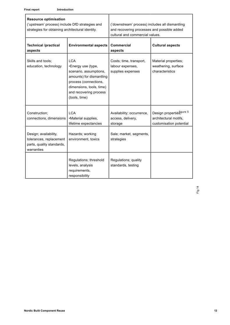
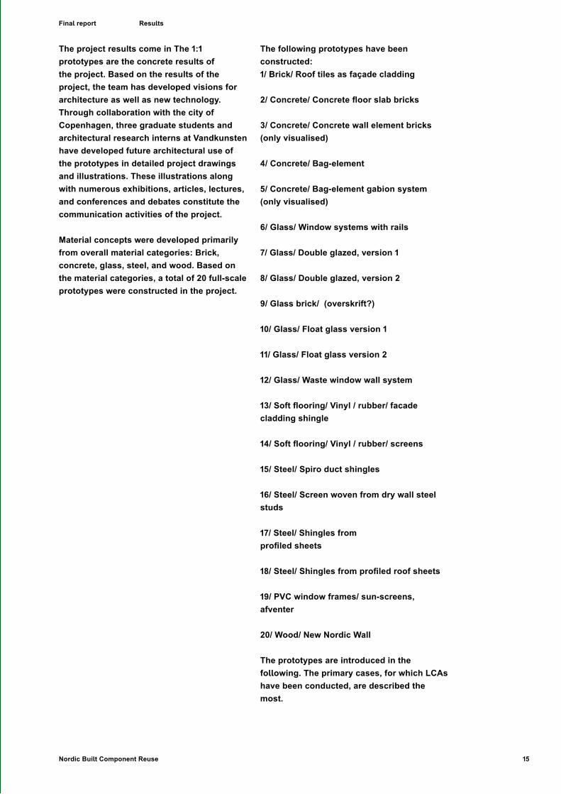
The project results come in The 1:1 prototypes are the concrete results of the project. Based on the results of the project, the team has developed visions for architecture as well as new technology.Through collaboration with the city of Copenhagen, three graduate students and architectural research interns at Vandkunsten have developed future architectural use of the prototypes in detailed project drawings and illustrations. These illustrations along with numerous exhibitions, articles, lectures, and conferences and debates constitute the communication activities of the project.
Material concepts were developed primarily from overall material categories: Brick, concrete, glass, steel, and wood. Based on the material categories, a total of 20 full-scale prototypes were constructed in the project.
The following prototypes have been constructed:1/ Brick/ Roof tiles as façade cladding
2/ Concrete/ Concrete floor slab bricks
3/ Concrete/ Concrete wall element bricks (only visualised)
4/ Concrete/ Bag-element
5/ Concrete/ Bag-element gabion system (only visualised)
6/ Glass/ Window systems with rails
7/ Glass/ Double glazed, version 1
8/ Glass/ Double glazed, version 2
9/ Glass brick/ (overskrift?)
10/ Glass/ Float glass version 1
11/ Glass/ Float glass version 2
12/ Glass/ Waste window wall system
13/ Soft flooring/ Vinyl / rubber/ facade cladding shingle
14/ Soft flooring/ Vinyl / rubber/ screens
15/ Steel/ Spiro duct shingles
16/ Steel/ Screen woven from dry wall steel studs
17/ Steel/ Shingles from profiled sheets
18/ Steel/ Shingles from profiled roof sheets
19/ PVC window frames/ sun-screens, afventer
20/ Wood/ New Nordic Wall
The prototypes are introduced in the following. The primary cases, for which LCAs have been conducted, are described the most.
16 Nordic Built Component Reuse
Final report Results
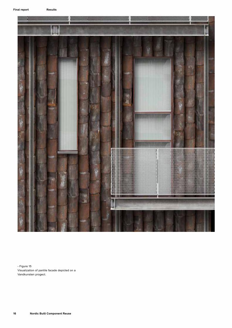
- Figure 15Visualization of pantile facade depicted on a Vandkunsten progect.
17Nordic Built Component Reuse
Final report Results
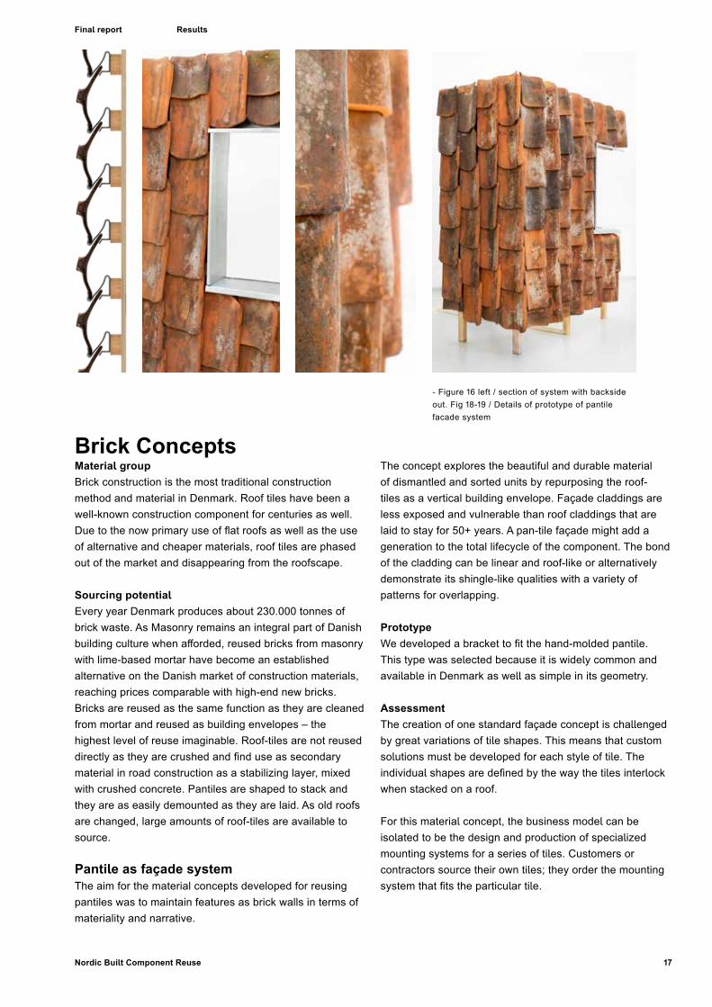
- Figure 16 left / section of system with backside out. Fig 18-19 / Details of prototype of pantile facade system
Brick ConceptsMaterial group Brick construction is the most traditional construction method and material in Denmark. Roof tiles have been a well-known construction component for centuries as well. Due to the now primary use of flat roofs as well as the use of alternative and cheaper materials, roof tiles are phased out of the market and disappearing from the roofscape.
Sourcing potential Every year Denmark produces about 230.000 tonnes of brick waste. As Masonry remains an integral part of Danish building culture when afforded, reused bricks from masonry with lime-based mortar have become an established alternative on the Danish market of construction materials, reaching prices comparable with high-end new bricks. Bricks are reused as the same function as they are cleaned from mortar and reused as building envelopes – the highest level of reuse imaginable. Roof-tiles are not reused directly as they are crushed and find use as secondary material in road construction as a stabilizing layer, mixed with crushed concrete. Pantiles are shaped to stack and they are as easily demounted as they are laid. As old roofs are changed, large amounts of roof-tiles are available to source.
Pantile as façade systemThe aim for the material concepts developed for reusing pantiles was to maintain features as brick walls in terms of materiality and narrative.
The concept explores the beautiful and durable material of dismantled and sorted units by repurposing the roof-tiles as a vertical building envelope. Façade claddings are less exposed and vulnerable than roof claddings that are laid to stay for 50+ years. A pan-tile façade might add a generation to the total lifecycle of the component. The bond of the cladding can be linear and roof-like or alternatively demonstrate its shingle-like qualities with a variety of patterns for overlapping.
PrototypeWe developed a bracket to fit the hand-molded pantile. This type was selected because it is widely common and available in Denmark as well as simple in its geometry.
AssessmentThe creation of one standard façade concept is challenged by great variations of tile shapes. This means that custom solutions must be developed for each style of tile. The individual shapes are defined by the way the tiles interlock when stacked on a roof.
For this material concept, the business model can be isolated to be the design and production of specialized mounting systems for a series of tiles. Customers or contractors source their own tiles; they order the mounting system that fits the particular tile.

18 Nordic Built Component Reuse
Final report Results
- Fi
gure
21
Vis
ualiz
atio
n of
pav
emen
t bas
ed o
n pr
otot
ype
of C
oncr
ete
Bric
ks-
Figu
re 2
0 P
roto
type
of C
oncr
ete
Bric
k Fa
cade

19Nordic Built Component Reuse
Final report Results
Concrete ConceptsMaterial groupConcrete is the most widely used construction material and the material group represents the bulk of construction waste. The production of concrete is especially energy consuming due to the firing processes involved in making cement.
Concrete is the biggest challenge for any repurposing strategy because the material components have been designed, reinforced and quality secured for particular purposes. It is difficult to test reinforcement and the condition of the elements. Challenges for sourcing and direct reuse include furthermore that concrete structures are joint-cast, which means that even buildings built from prefabricated concrete elements cannot be separated undamaged as the conventional concrete construction systems require that joints between elements are cast together for optimal structural performance. In Denmark, more than 90% of concrete is reused crushed. At present, the most socioeconomically feasible use of waste concrete is for road and parking pavement bases where the rubble replaces virgin aggregate.18
The porous material can be contaminated with Polychlorinated Biphenyls (PCBs), a toxin widely used in construction materials between 1950s and 1977. PCB is another obstacle for concrete reuse.
Concrete slabs as bricks and pavementThis series of concrete concepts is inspired by formats of structural elements and we explore technical flaws as an aesthetic feature such as exposing reinforcement bars that causes rust to stain the facades
18 Energistyrelsen 2015
Fig 22-25 / Visualizations of use of concrete bricks.

20 Nordic Built Component Reuse
Final report Results
Diamond blade saws are used to cut pretensioned concrete elements in factories. It is costly because the blades are rapidly worn when cutting the hard concrete and they require frequent maintenance and exchange. After the dismantling the concrete slabs are sliced with circular saws with diamond blades. The concept is to slice deck elements and use the slices as thin sheet panels for building envelopes or as pavement.
It was not possible to test the slicing process on site in the project so prototypes are mockups cast in new molds and manufactured to test the weathered look and the general appearance of the concrete facades.
It is possible to produce products of decent aesthetical quality by cutting bricks as differently oriented sections through hollow core elements.
The concept faces a number of critical points. It is expensive to cut; it requires strict safety measures if cutting station is placed on the construction site; elements are heavy and may require lifting gear to handle. There are requirements for testing for toxins; there are technical challenges to ensure that the concrete is not damaged as well as the immediate issue concerning reinforcement and
material composition: that the concrete is produced and reinforced to fulfil particular requirements that are far from the future use.
Commercial assessmentTechnical obstacles:
• All elements need empirical testing
• Slized concrete will be reinforced for another purpose. The prototypes have concrete panels that appear as traditionally fibrereinforced concrete.
• Need to develop effective sourcing/slicing/handling technology – imagined as the SlabCutterBot
Concrete rubble as sack-bricks
Concept This concept is based on the condition that concrete is most easily sourced as rubble. The rubble can be stuffed in sacks as a kind of rubble-sack-brick. The static properties are very passive and shape and dimensions are notoriously inaccurate.
- Figure 26-27Left, concrete rubble. Right, visualization of bricks stacked in iron frames

21Nordic Built Component Reuse
Final report Results
- Fi
gure
28
/ det
ail o
f pro
toty
pe
22 Nordic Built Component Reuse
Final report
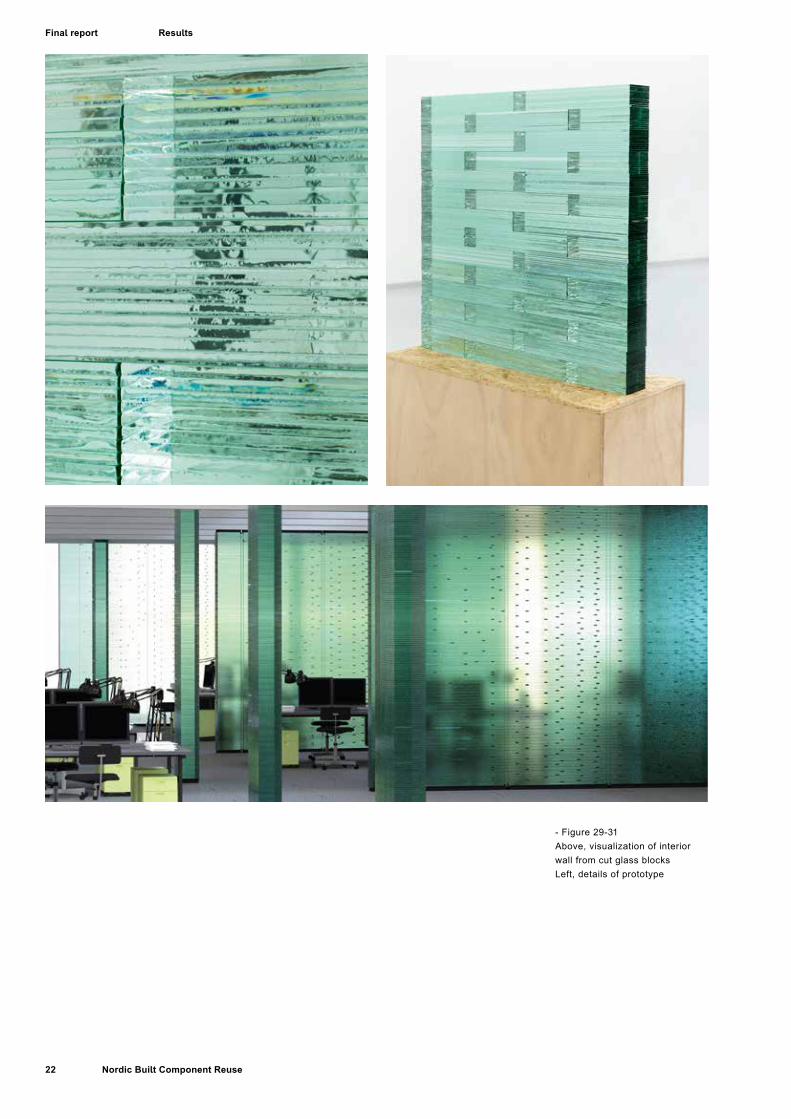
- Figure 29-31Above, visualization of interior wall from cut glass blocksLeft, details of prototype
Results

23Nordic Built Component Reuse
Final report
Glass ConceptsWindow production is a major component industry in the construction sector.Glass facades and windows mark the cosmetic face of architecture and the market constantly demands new functional and aesthetic opportunities to distinguish built projects. The technological development in ways to shape glass combined with the focus of development has lowered the life span of windows in most buildings severely compared to old wood-frame windows that could last centuries. Especially in the private consumer markets, glazed windows are a commonly replaced component leaving a large quantity of double-glazed windows as waste. Windows are easily sourced as components.Presently, waste glass is melted and reused for the production of new glass sheets or glass-based insulation19.
We have developed several ways to assign new function and aesthetic value to this group of material components.
Glass building envelope from double glazed panes ConceptDouble-glazed windowpanes can be used for building envelopes when mounted on battens and fixed with adjustable wire-systems to provide flexibility. In this way differences in dimensions can become a part of the façade expression.
19 https://www.a-r-c.dk/media/120916/vejledning_sorter-dit-affald.pdf p. 2
- Figure 32-34Illustration of facade system with preused windows and wires.
Results
24 Nordic Built Component Reuse
Final report
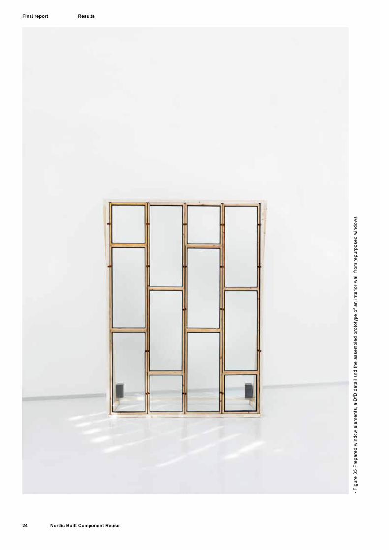
- Fi
gure
35
Pre
pare
d w
indo
w e
lem
ents
, a D
fD d
etai
l and
the
asse
mbl
ed p
roto
type
of a
n in
terio
r w
all f
rom
rep
urpo
sed
win
dow
s
Results

25Nordic Built Component Reuse
Final report
Glass Building Bricks from waste window panes
Float-glass from insulating glass or single pane windows can be cut up – potentially in an automatized process – and assembled in brick-like units by means of low viscosity silicone. PCB from old edge sealants can be cut out and collected. (Fig 29-31)
Glass Interior wall from repurposed windows
Raw materialOld windows are overflowing the market for reused components. The quality of the wood is often very high and the dimensions most often comply roughly with traditional standards.
ConceptExact dimensions can be obtained by planning the frames. This makes it possible to adapt window elements to a frame system of steel, wood or aluminium. The prototyped version uses wedges for fixation, a typical DfD solution to enable easy disassembly. The outer layer of weathered wood and paint is recut from all 12 sides of the window frame. This process is also functions to add value through trimming the window profile to a new and more refined, slim look. The wooden frames are given a traditional outdoor treatment, paint or oil.(Fig 35-37)
Results
- Figure 36-37Cut window frames durin prototype production, right, detail of prototype
26 Nordic Built Component Reuse
Final report
- Fi
gure
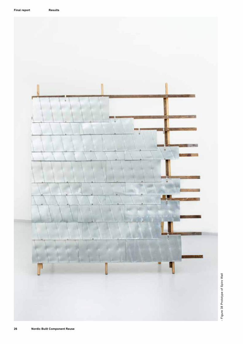
38
Pro
toty
pe o
f Spi
ro W
all
Results
27Nordic Built Component Reuse
Final report
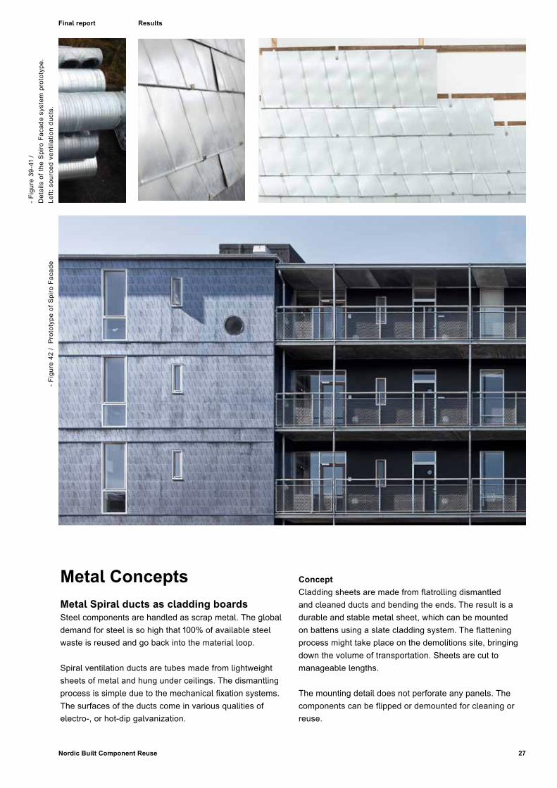
Metal ConceptsMetal Spiral ducts as cladding boardsSteel components are handled as scrap metal. The global demand for steel is so high that 100% of available steel waste is reused and go back into the material loop.
Spiral ventilation ducts are tubes made from lightweight sheets of metal and hung under ceilings. The dismantling process is simple due to the mechanical fixation systems. The surfaces of the ducts come in various qualities of electro-, or hot-dip galvanization.
ConceptCladding sheets are made from flatrolling dismantled and cleaned ducts and bending the ends. The result is a durable and stable metal sheet, which can be mounted on battens using a slate cladding system. The flattening process might take place on the demolitions site, bringing down the volume of transportation. Sheets are cut to manageable lengths.
The mounting detail does not perforate any panels. The components can be flipped or demounted for cleaning or reuse.
- Fi
gure
42
/ P
roto
type
of S
piro
Fac
ade
- Fi
gure
39-
41 /
Det
ails
of t
he S
piro
Fac
ade
syst
em p
roto
type
. Le
ft: s
ourc
ed v
entil
atio
n du
cts.
Results
28 Nordic Built Component Reuse
Final report
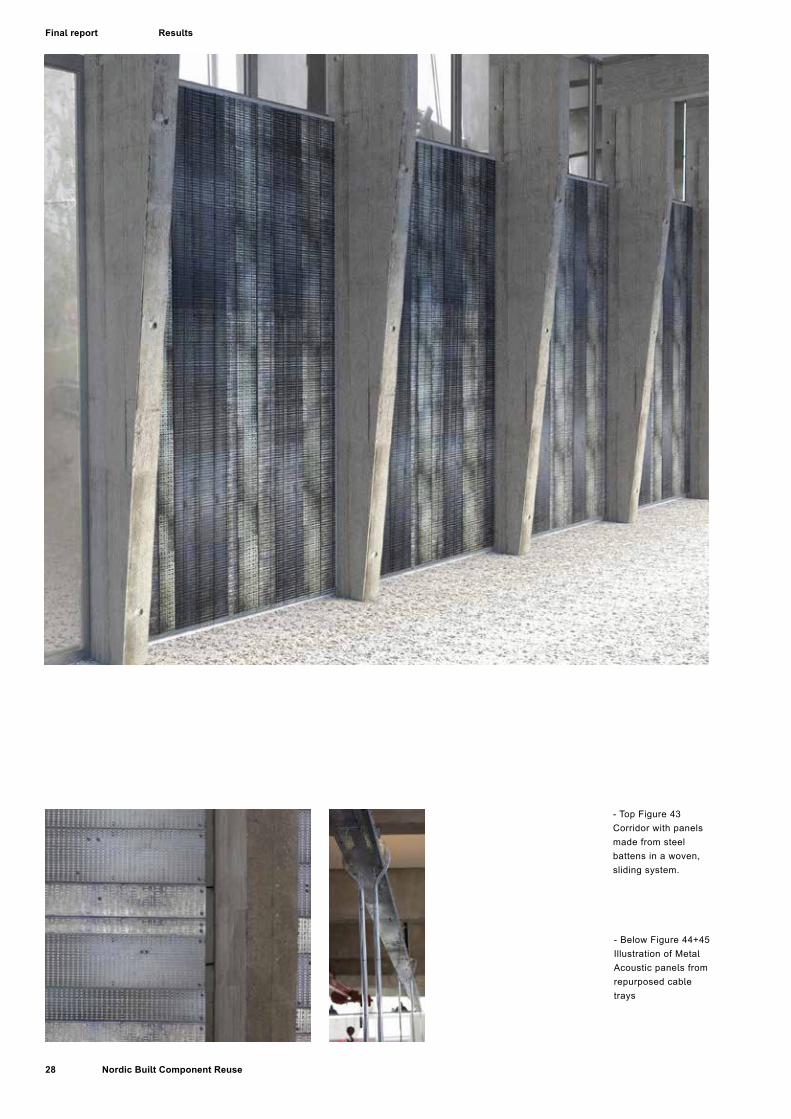
- Top Figure 43Corridor with panels made from steel battens in a woven, sliding system.
- Below Figure 44+45Illustration of Metal Acoustic panels from repurposed cable trays
Results

29Nordic Built Component Reuse
Final report
AestheticsWe really like the patterns of the façade. The diagonal lines form a new ornamental pattern on the surface. The concept is so simple and easily applicable.
Environment and economyCleaning the ducts may prove expensive in time as well as possible toxic waste to be deposited. Metal has a near 100% reuse ratio due to the high demand for metals at secondary qualities (Source?). Reusing spiro ducts as facades will postpone the energy consuming process of remelting but the high demand for steel may result in primary steel.
The mounting time is an economic factor for façade systems. The montage of the Spiro duct-prototype is made simple: a bracket holds the sheet without the need for holes. This makes the sheet reusable, easily mounted as well as properly sealed from air and water.Variations in the sizes of ducts and thus sheets will impact the speed of montage but it will also increase the variations of expression.
Steel - Braided thin-plate studs for partitioning wall cladding
Original componentThe lifetime of thin-plate steel-studs in partitioning walls is short due to frequent refurbishment of office buildings in particular. As dry wall partitioning walls have short average functional lifetimes, large numbers of steel-studs are discarded and end as steel-scrap for remelting.
Results
- Figure 46Visualization of interior screen from woven metal studs.
- Figure 47Metal studs fra dry wall.

30 Nordic Built Component Reuse
Final report
- Figure 48-51 Steel roofing sheets turned into facade shingles- Right image of surface painted shingles
< Figure 52Photo collage that visualizes the implementation of the metal shingle concept.
Results

31Nordic Built Component Reuse
Final report
ConceptIn case of the partition wall this is done in two ways; 1: By reusing components from dismantled walls, and 2: By designing a partitioning wall system, which enables easy dismantling and reuse.
Decorative and robust cladding can be produced by weaving flat studs that have been cleaned and flattened. The concept is imagined for interior purposes; walls and ceilings.
Metal Shingles from repurposed thin-plate profiles
ConceptUneven sheets of thin-plate steel, zinc or copper can be flattened and cut to standardised dimensions, providing a basis for different shingle cladding systems mounted like shingles
of slate or wood. The illustrations show raw sheets as well as folded shingles of a more ornate nature.
Metal Acoustic panels from repurposed cable trays
Raw materialCable trays are used in offices and frequently discarded during renovation and refurbishment work.
ConceptThe perforated material is suited for acoustic panels in combination with a noise absorbent, and the profiling makes it easy to assemble a stable panel-construction. An alternative repurposing of discarded cable-trays is as sun- or light-screens, where the perforation imparts a fabric-like expression.
- Figure 53Photo collage to visualize the implementation of the metal shingle concept.
Results

32 Nordic Built Component Reuse
Final report Results
- Figure 54Prototype of screen woven from reused rubber floor

33Nordic Built Component Reuse
Final report
- Figure 55+56Prototypes of Woven facade screens reusing rubber flooring (black) and vinyl (colored)
Soft Flooring ConceptsRaw materialVinyl flooring as façade panels
Figure 16 Facade concept reusing vinyl flooring
Soft flooring concept: Rubber flooring repurposed as shielding screensRaw materialConcept
Results

34 Nordic Built Component Reuse
Final report
Fig
57 /
Vis
ualiz
atio
n of
the
New
Nor
dic
Wal
lFi
g 58
-59
/ Im
ages
of p
roto
type
uni
ts
Results
35Nordic Built Component Reuse
Final report
Wood ConceptsWood - New Nordic Wall
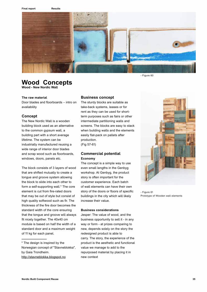
The raw materialDoor blades and floorboards – intro on availability
Concept The New Nordic Wall is a wooden building block used as an alternative to the common gypsum wall, a building part with a short average lifetime. The system can be industrially manufactured reusing a wide range of interior door blades and scrap wood such as floorboards, windows, doors, panels etc.
The block consists of 3 layers of wood that are shifted mutually to create a tongue and groove system allowing the block to slide into each other to form a self-supporting wall.* The core element is cut from fire-rated doors that may be out of style but consist of high quality softwood such as fir. The thickness of the fire door becomes the standard width of the core ensuring that the tongue and groove will always fit nicely together. The 40x40 cm module is based on half the width of a standard door and a maximum weight of 11 kg for each panel.
Business conceptThe sturdy blocks are suitable as take-back systems, leases or for rent as they can be used for short-term purposes such as fairs or other intermediate partitioning walls and screens. The blocks are easy to stack when building walls and the elements easily flat-pack on pallets after production. (Fig 57-61)
Commercial potentialEconomyThe concept is a simple way to use even small lengths in the Genbyg workshop. At Genbyg, the product story is often important for the customer experience. Each batch of wall elements can have their own story of the doors or floors of specific buildings in the city which will likely increase their value.
Business considerationsJesper: The value of wood, and the business opportunity to sell it - in any way or form - at prizes comparing to new, depends solely on the story the redesigned product is able tocarry. The story, the experience of the product is the aesthetic and functional value we manage to add to the repurposed material by placing it in new context
- Figure 61Prototype of Wooden wall elements
- Figure 60
Results
* The design is inspired by the Norwegian concept of "Stavneblokka", by Gaia Trondheim. http://stavneblokka.blogspot.no

36 Nordic Built Component Reuse
Final report
Life Cycle Assessment Screening of Repurposed Construction Products Life Cycle Assessment (LCA) is a standardized method to evaluate the environmental impacts of products and/or product systems. In the Nordic Built Component Reuse project LCA has been used to compare the newly developed, but reuse-based building products with their new equivalents with the aim to show how the reused products compare environmentally and to identify which material groups will make the most sense to be reused from an environmental point of view.
37Nordic Built Component Reuse
Final report
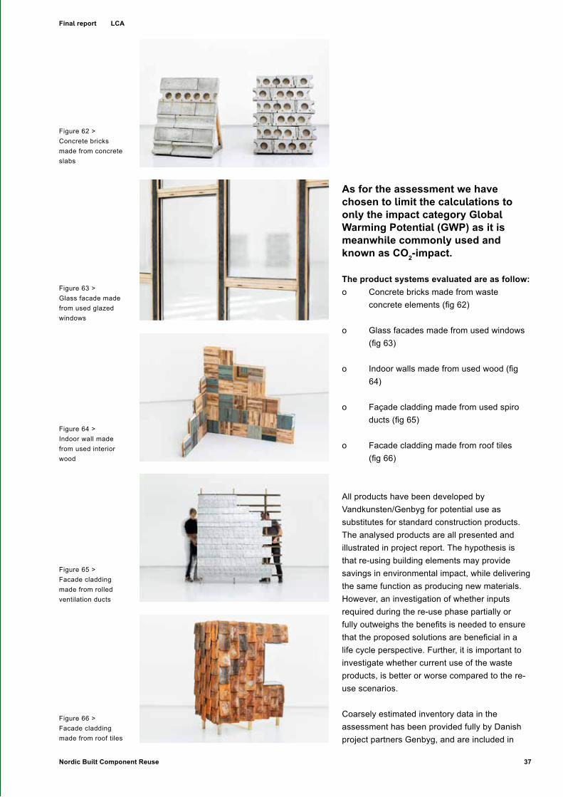
As for the assessment we have chosen to limit the calculations to only the impact category Global Warming Potential (GWP) as it is meanwhile commonly used and known as CO2-impact.
The product systems evaluated are as follow: o Concrete bricks made from waste
concrete elements (fig 62)
o Glass facades made from used windows (fig 63)
o Indoor walls made from used wood (fig 64)
o Façade cladding made from used spiro ducts (fig 65)
o Facade cladding made from roof tiles (fig 66)
All products have been developed by Vandkunsten/Genbyg for potential use as substitutes for standard construction products. The analysed products are all presented and illustrated in project report. The hypothesis is that re-using building elements may provide savings in environmental impact, while delivering the same function as producing new materials. However, an investigation of whether inputs required during the re-use phase partially or fully outweighs the benefits is needed to ensure that the proposed solutions are beneficial in a life cycle perspective. Further, it is important to investigate whether current use of the waste products, is better or worse compared to the re-use scenarios.
Coarsely estimated inventory data in the assessment has been provided fully by Danish project partners Genbyg, and are included in
Figure 62 >Concrete bricks made from concrete slabs
Figure 63 >Glass facade made from used glazed windows
Figure 64 >Indoor wall made from used interior wood
Figure 65 >Facade cladding made from rolled ventilation ducts
Figure 66 >Facade cladding made from roof tiles
LCA

38 Nordic Built Component Reuse
Final report
the appendix. This includes energy use estimates for different operations in the deconstruction/shaping/reassembly stage, materials, as well as time use estimates.
Lifetimes for the analyzed products, as well as for substitution products, have been given by Genbyg. Maintenance and final EOL are assumed to be equal for replacement products and the re-use products. Due to lack of information, substitution assumption used at time zero, are also applied at end-of-life of the products. For future EOL of steel and aluminum this assumption is discussed where relevant. A default recovery rate of 90% for the building components in question is applied to all materials that are recycled. For heat recovery, an efficiency of 70% is assumed, and heat is assumed to replace heat produced by oil combustion. Aluminium and steel recycling replaces virgin material. Therefore, virgin material is also
used as the input for the alternative products where steel or aluminium is used. Glass is assumed to be landfilled, and concrete waste is assumed to replace gravel production.
For all systems the re-use scenario is compared to one or more alternative scenarios. This implies that the alternative scenario includes waste treatment/recycling (w/ potential substitution of new material), in addition to producing the alternative solution itself. For the re-use scenarios inputs required from the building site, to finished product, are included. The reclaimed material itself is considered emissions free, since the emissions associated with their production are “sunk cost”. Figure 1: Overview of comparison scope for the systems illustrates this set-up.For operations that are certain to take place in Denmark, Danish electricity mix from Ecoinvent is applied. Otherwise European or global average
data is used.General workshop inputs (building, energy) has been coarsely approximately by assuming 1 m2 wall construction takes up 20m2 of workshop space, for the indicated time use presented by Genbyg. Further, we assume 200kwh/m2-yr energy use in the workshop (in addition to the processing specific energy use).
The building itself is approximated by a hall building from ecoinvent with an assumed lifetime of 50 yrs, and estimated 1900 hrs of useful workshop time per year. Due to lack of data, all transport in the system (from collection site to workshop, or to waste collection site) has been assumed to be 25 km, and performed by either a small truck (to workshop) or large truck (to waste collection site).
Ecoinvent v31 has been used as a
1 http://www.ecoinvent.ch/
< Figure 67Overview of comparison scope for the systems
LCA
39Nordic Built Component Reuse
Final report
background database, and Simapro2 has been used for modelling the system. For impact assessment we use selected categories (climate change and a single score endpoint indicator) based on the ReCiPe3 method. This contains “equivalency factors” for the different types of emissions, and aggregates the results on either a “midpoint” level (such as the GWP100 indicator for climate change), or endpoint level (in this case an aggregated, weighted indicator for total environmental impact). For cases where the climate effect of CO2 emissions with biogenic origin may be significant, results are presented for both a “carbon neutral” assumption, as well as an assumption where biogenic CO2 from the waste treatment has the same GWP-factor as other CO2. For the weighted “total impact” indicator, we have included EOL biogenic CO2 emissions with the same impact as other CO2, as default.
Further, the indicator for total impact is “mPt”, which does not have a specific physical meaning, but presents a result to be compared to alternatives. We have used the version “I/A” in the calculations, due to the short time horizon applied in this method, which we feel is closer to the current decision makers priorities, than other versions applying a longer time horizon, and additions, less proven,
2 http://www.pre-sustainability.com/simapro
3 http://www.lcia-recipe.net/
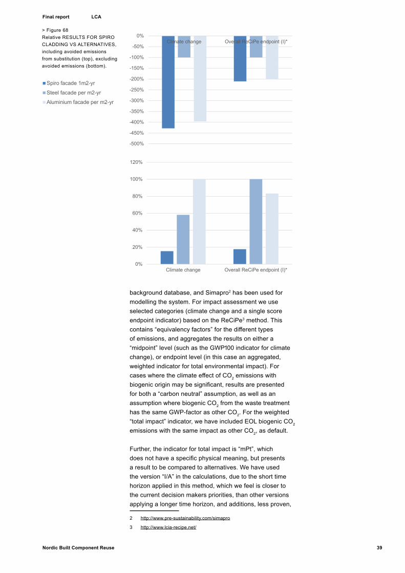
> Figure 68Relative RESULTS FOR SPIRO CLADDING VS ALTERNATIVES, including avoided emissions from substitution (top), excluding avoided emissions (bottom).
-500%
-450%
-400%
-350%
-300%
-250%
-200%
-150%
-100%
-50%
0%Climate change Overall ReCiPe endpoint (I)*
Spiro facade 1m2-yr
Steel facade per m2-yr
Aluminium facade per m2-yr
0%
20%
40%
60%
80%
100%
120%
Climate change Overall ReCiPe endpoint (I)*
Spiro facade 1m2-yr
Steel facade per m2-yr
Aluminium facade per m2-yr
LCA
40 Nordic Built Component Reuse
Final report
impact routes.
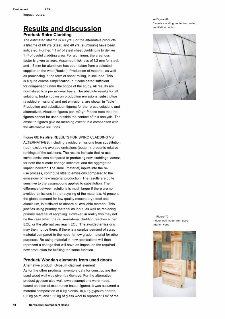
Results and discussionProduct/ Spiro CladdingThe estimated lifetime is 40 yrs. For the alternative products a lifetime of 60 yrs (steel) and 40 yrs (aluminum) have been indicated. Further, 1,1 m2 of steel sheet cladding is to deliver 1m2 of useful cladding area. For aluminum, the area loss factor is given as zero. Assumed thickness of 1,2 mm for steel, and 1,5 mm for aluminum has been taken from a selected supplier on the web (Ruukki). Production of material, as well as processing in the form of sheet rolling, is included. This is a quite coarse simplification, but considered sufficient for comparison under the scope of the study. All results are normalized to a per m2-year basis. The absolute results for all solutions, broken down on production emissions, substitution (avoided emissions) and net emissions, are shown in Table 1: Production and substitution figures for the re-use solutions and alternatives. Absolute figures per m2-yr. Please note that the figures cannot be used outside the context of this analysis. The absolute figures give no meaning except in a comparison with the alternative solutions..
Figure 68: Relative RESULTS FOR SPIRO CLADDING VS ALTERNATIVES, including avoided emissions from substitution (top), excluding avoided emissions (bottom). presents relative rankings of the solutions. The results indicate that re-use saves emissions compared to producing new claddings, across for both the climate change indicator, and the aggregated impact indicator. The small (material) inputs into the re-use process, contribute little to emissions compared to the emissions of new material production. The results are quite sensitive to the assumptions applied to substitution. The difference between solutions is much larger if there are no avoided emissions in the recycling of the materials. At present, the global demand for low quality (secondary) steel and aluminium, is sufficient to absorb all available material. This justifies using primary material as input, as well as replacing primary material at recycling. However, in reality this may not be the case when the reuse-material cladding reaches either EOL, or the alternatives reach EOL. The avoided emissions may then not be there, if there is a surplus demand of scrap material compared to the need for low grade material for other purposes. Re-using material in new applications will then represent a change that will have an impact on the required new production for fulfilling the same function.
Product/ Wooden elements from used doorsAlternative product: Gypsum clad wall elementAs for the other products, inventory data for constructing the used wood wall was given by Genbyg. For the alternative product gypsum clad wall, own assumptions were made, based on internal experience based figures. It was assumed a material composition of 5 kg planks, 18,4 kg gypsum boards, 0,2 kg paint, and 1,65 kg of glass wool to represent 1 m2 of the
— Figure 70Indoor wall made from used interior wood
— Figure 69Facade cladding made from rolled ventilation ducts
LCA

41Nordic Built Component Reuse
Final report
alternative wall.
The results in FIGURE 71: RELATIVE RESULTS FOR USED DOOR WOODEN WALL VS ALTERNATIVES, INCLUDING AVOIDED EMISSIONS FROM SUBSTITUTION (TOP), EXCLUDING AVOIDED EMISSIONS (BOTTOM). show that if we assume biogenic emissions of CO2 to be “climate neutral” (which is current mainstream practice), the gypsum clad wall alternative scores better. This is due to the substitution assumption (heat from wood replaces fossil fuel combustion) in which the wood in the two cases combusted with heat recovery. Since the clad wall alternative has more wood in total, the avoided emissions are larger. However, for all other emissions occurring upstream the waste available, we apply the “sunk cost”-perspective. The (inaccurate) “carbon neutral” assumption for wood combustion rests upon an assumption that upstream uptake of CO2 equals the CO2 from combustion. We consider the “sunk cost” assumption to be just as relevant to carbon uptake in wood growth. This implies the relevant characterization factor for biogenic CO2 from the waste wood is similar to any other CO2 emitted, i.e 1. using this factor the re-use solution comes out considerably better.
This leads to a very interesting discussion on how to deal with products that potentially could be reused at a higher
complexity level, but that have a high calorific value that in an EOL scenario actually would substitute fuels and by that will give a more favourable result for the LCA (EOL stage) where the materials are combusted contrary to a reuse scenario, where also further positive effects can or will occure (as eg. carbon storage/ delayed carbon emissions)Note that in this assessment, we have not included any positive effect for delayed emissions. This means that temporary storage of carbon in wood, is treated with the same impact factor at the end of its lifetime, as today. Recent studies have published characterization factors for temporary carbon storage as well as biogenic emissions (Guest, Bright, Cherubini, & Strømman, 2013)short rotation woody crops, medium rotation temperate forests, and long rotation boreal forests. For each feedstock type and biogenic carbon storage pool, we quantify the carbon cycle climate impact due to the skewed time distribution between emission and sequestration fluxes in the bio- and anthroposphere. Additional consideration of the climate impact from albedo changes in forests is also illustrated for the boreal forest case. When characterizing climate impact with global warming potentials (GWP. In favour of the re-use solution for wood is the argument about delayed emissions as a value in itself, as well as the fact that part of the wood material is still available in solid form at the end of life. Waste treatment options may be different at this point in the future, and climate impacts may be different.
-200%
-150%
-100%
-50%
0%
50%
100%
150%
Climate change Overall ReCiPe endpoint(I)*
Wood wall 1m2-yr
Gypsum clad wall 1m2-yr
0%
20%
40%
60%
80%
100%
120%
Climate change Overall ReCiPe endpoint(I)*
Wood wall 1m2-yr
Gypsum clad wall 1m2-yr
< Figure 71RELATIVE RESULTS FOR used door wooden wall VS ALTERNATIVES, INCLUDING AVOIDED EMISSIONS FROM SUBSTITUTION (TOP), EXCLUDING AVOIDED EMISSIONS (BOTTOM).
-200%
-150%
-100%
-50%
0%
50%
100%
150%
Climate change Overall ReCiPe endpoint(I)*
Wood wall 1m2-yr
Gypsum clad wall 1m2-yr
0%
20%
40%
60%
80%
100%
120%
Climate change Overall ReCiPe endpoint(I)*
Wood wall 1m2-yr
Gypsum clad wall 1m2-yr
LCA

42 Nordic Built Component Reuse
Final report
< Figure 72RELATIVE RESULTS FOR used window CASE VS ALTERNATIVES, INCLUDING AVOIDED EMISSIONS FROM SUBSTITUTION (TOP), EXCLUDING AVOIDED EMISSIONS (BOTTOM).
Product/ Used window glass facadeAlternative product: Glass façade
As for the other products, inventory data for constructing the used window based façade wall was given by Genbyg. For the alternative product new glass based wall, an estimated material composition was defined by Genbyg. The façade is mainly based on glass, with some aluminium and rubber components. The data is included in the Appendix. The composition of the used glass is both wood, glass and aluminium. We assume similar recovery rates and substitution effects for these materials, as for the rest of the re-use material, even though they are more embedded than other more “pure” components. For glass we have assumed no substitution and that all material goes to inert material landfill.The relative results to deliver 1m2-yr façade covering are presented in Figure 72: RELATIVE RESULTS FOR used window CASE VS ALTERNATIVES, INCLUDING AVOIDED EMISSIONS FROM SUBSTITUTION (TOP), EXCLUDING AVOIDED EMISSIONS (BOTTOM).. Since there is a considerable amount of wood in the windows, we include the climate change indicator which treats those combustion emissions similar to fossil emissions. Whether including the substitution effects or not, the re-use scenario has lower impact than the new glass façade. The difference becomes larger if we include the climate impacts from wood combustion.
— Figure 73Glass facade made from used glazed windows
-150%
-100%
-50%
0%
50%
100%
150%
Climate change Overall ReCiPe endpoint(I)*
Used glass facade 1m2-yr
New glass facade 1m2-yr
0%
20%
40%
60%
80%
100%
120%
Climate change Overall ReCiPe endpoint(I)*
Used glass facade 1m2-yr
New glass facade 1m2-yr
-150%
-100%
-50%
0%
50%
100%
150%
Climate change Overall ReCiPe endpoint(I)*
Used glass facade 1m2-yr
New glass facade 1m2-yr
0%
20%
40%
60%
80%
100%
120%
Climate change Overall ReCiPe endpoint(I)*
Used glass facade 1m2-yr
New glass facade 1m2-yr
LCA
43Nordic Built Component Reuse
Final report
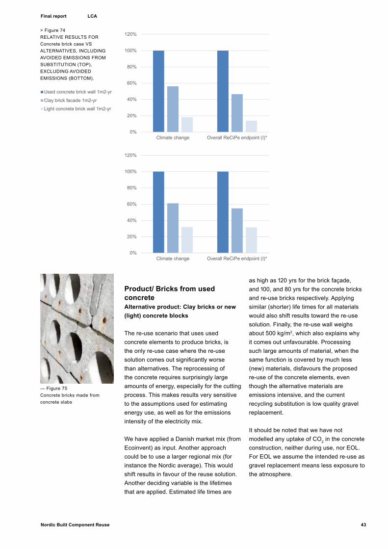
Product/ Bricks from used concreteAlternative product: Clay bricks or new (light) concrete blocks
The re-use scenario that uses used concrete elements to produce bricks, is the only re-use case where the re-use solution comes out significantly worse than alternatives. The reprocessing of the concrete requires surprisingly large amounts of energy, especially for the cutting process. This makes results very sensitive to the assumptions used for estimating energy use, as well as for the emissions intensity of the electricity mix.
We have applied a Danish market mix (from Ecoinvent) as input. Another approach could be to use a larger regional mix (for instance the Nordic average). This would shift results in favour of the reuse solution. Another deciding variable is the lifetimes that are applied. Estimated life times are
as high as 120 yrs for the brick façade, and 100, and 80 yrs for the concrete bricks and re-use bricks respectively. Applying similar (shorter) life times for all materials would also shift results toward the re-use solution. Finally, the re-use wall weighs about 500 kg/m2, which also explains why it comes out unfavourable. Processing such large amounts of material, when the same function is covered by much less (new) materials, disfavours the proposed re-use of the concrete elements, even though the alternative materials are emissions intensive, and the current recycling substitution is low quality gravel replacement.
It should be noted that we have not modelled any uptake of CO2 in the concrete construction, neither during use, nor EOL. For EOL we assume the intended re-use as gravel replacement means less exposure to the atmosphere.
> Figure 74RELATIVE RESULTS FOR Concrete brick case VS ALTERNATIVES, INCLUDING AVOIDED EMISSIONS FROM SUBSTITUTION (TOP), EXCLUDING AVOIDED EMISSIONS (BOTTOM).
0%
20%
40%
60%
80%
100%
120%
Climate change Overall ReCiPe endpoint (I)*
Used concrete brick wall 1m2-yr
Clay brick facade 1m2-yr
Light concrete brick wall 1m2-yr
0%
20%
40%
60%
80%
100%
120%
Climate change Overall ReCiPe endpoint (I)*
Used concrete brick wall 1m2-yr
Clay brick facade 1m2-yr
Light concrete brick wall 1m2-yr
0%
20%
40%
60%
80%
100%
120%
Climate change Overall ReCiPe endpoint (I)*
Used concrete brick wall 1m2-yr
Clay brick facade 1m2-yr
Light concrete brick wall 1m2-yr
0%
20%
40%
60%
80%
100%
120%
Climate change Overall ReCiPe endpoint (I)*
Used concrete brick wall 1m2-yr
Clay brick facade 1m2-yr
Light concrete brick wall 1m2-yr
— Figure 75Concrete bricks made from concrete slabs
LCA

44 Nordic Built Component Reuse
Final report
< Figure 76RELATIVE RESULTS FOR roof tile CASE VS ALTERNATIVES, INCLUDING AVOIDED EMISSIONS FROM SUBSTITUTION (TOP), EXCLUDING AVOIDED EMISSIONS (BOTTOM).
Product/ Façade from roof tilesAlternative product: Steel sheet cladding or brick facade
Inventory data for the roof tile facade is included in the Appendix supplied by the producer. The estimated lifetime is 40 yrs. For the alternative products a lifetime of 60 yrs (steel) and 120 yrs (bricks) have been indicated. Further, about 48 kg used roof tiles is needed to deliver 1m2 of useful cladding area. All results are normalized to a per m2-yr basis. The absolute results for all solutions, broken down on production emissions, substitution (avoided emissions) and net emissions, are shown in Table 1: Production and substitution figures for the re-use solutions and alternatives. Absolute figures per m2-yr. Please note that the figures cannot be used outside the context of this analysis. The absolute figures give no meaning except in a comparison with the alternative solutions..Figure 76: RELATIVE RESULTS FOR roof tile CASE VS ALTERNATIVES, INCLUDING AVOIDED EMISSIONS FROM SUBSTITUTION (TOP), EXCLUDING AVOIDED EMISSIONS (BOTTOM). presents relative rankings of the solutions. The results indicate that re-use saves emissions compared to producing new facades, for both the climate change indicator, and the aggregated impact indicator. The small (material) inputs into the re-use process, contribute little to emissions compared to the emissions of new material production.
-20%
0%
20%
40%
60%
80%
100%
120%
Climate change Overall ReCiPe endpoint (I)*
Tile facade 1m2-yr
Clay brick facade 1m2-yr
Steel facade per m2-yr
0%
20%
40%
60%
80%
100%
120%
Climate change Overall ReCiPe endpoint (I)*
Tile facade 1m2-yr
Clay brick facade 1m2-yr
Steel facade per m2-yr
-20%
0%
20%
40%
60%
80%
100%
120%
Climate change Overall ReCiPe endpoint (I)*
Tile facade 1m2-yr
Clay brick facade 1m2-yr
Steel facade per m2-yr
0%
20%
40%
60%
80%
100%
120%
Climate change Overall ReCiPe endpoint (I)*
Tile facade 1m2-yr
Clay brick facade 1m2-yr
Steel facade per m2-yr
— Figure 77Facade cladding made from roof tiles
LCA

45Nordic Built Component Reuse
Final report
Documentation screening LCA of re-use solutions_JSK - AM20160525 9
Impact category Climate change
Climate change, incl biogenic=0,61
Overall ReCiPe endpoint
Unit kg CO2 eq kg CO2 eq mPt Used concrete brick wall 1m2-yr Production 0,78 0,82 62
Substitution -0,16 -0,16 -15Net 0,63 0,66 47
Clay brick facade 1m2-yr Production 0,48 0,48 34Substitution -0,13 -0,13 -12Net 0,35 0,35 22
Light concrete brick wall 1m2-yr Production 0,25 0,25 20Substitution -0,14 -0,14 -13Net 0,11 0,12 7
Used glass facade 1m2-yr Production 0,16 0,47 44Substitution -0,77 -0,77 -59Net -0,61 -0,30 -14
New glass facade 1m2-yr Production 0,91 1,34 127 Substitution -1,41 -1,41 -108Net -0,50 -0,07 19
Spiro facade 1m2-yr Production 0,29 0,29 37Substitution -1,42 -1,43 -390Net -1,13 -1,14 -353
Steel facade per m2-yr Production 1,11 1,13 210 Substitution -1,37 -1,38 -377Net -0,26 -0,25 -167
Aluminium facade per m2-yr Production 1,91 1,92 174 Substitution -2,96 -2,97 -512Net -1,05 -1,05 -338
Wood wall 1m2-yr Production 0,22 0,96 80Substitution -0,82 -0,82 -59Net -0,60 0,13 21
Gypsum clad wall 1m2-yr Production 0,46 1,72 147 Substitution -1,40 -1,40 -100Net -0,95 0,32 47
Tile facade 1m2-yr Production 0,06 0,18 26Substitution -0,13 -0,13 -10Net -0,07 0,06 17
Clay brick facade 1m2-yr Production 0,43 0,44 30Substitution -0,02 -0,02 -2Net 0,41 0,41 28
Steel facade per m2-yr Production 0,90 0,92 187 Substitution -0,41 -0,41 -118Net 0,50 0,51 69
GENERAL DISCUSSION AND CONCLUDING REMARKS
> Figure 78Table showing production and substitution figures for the re-use solutions and alternatives. Absolute figures per m2-yr. Please note that the figures cannot be used outside the context of this analysis. The absolute figures give no meaning except in a comparison with the alternative solutions.
LCA

46 Nordic Built Component Reuse
Final report
Discussion

47Nordic Built Component Reuse
Final report
General discussion of LCA and concluding remarksFrom the results presented in the previous sections it is evident that reusing building materials is favourable in all those cases where the energy and/or material input for sourcing, processing and manufacturing of the “reuse material” is lower than the inputs necessary to produce new materials.As for the chosen examples in this study, all reused products except the concrete bricks are favourable from an environmental point-of-view compared to the new products replaced. The concrete brick example is interesting as it shows how difficult it is to find a reuse scenario for concrete at a higher “integration level”, which not only returns a useful product, but is also favourable compared to the standard EOL-scenario in which concrete is crushed and replaces gravel. The assessment of the concrete brick wall shows app. 5 times higher impacts for GWP than the newly produced light concrete block, this implies that also a further optimization or upscaling of the reuse process will not render the reuse product considerably better compared to the available alternatives.The three other examples, glass façade, spiro façade and wooden interior wall, all show clearly that reused products can substitute new products with an environmental advantage compared to new products.
The reuse process is low on energy and/or material input in these cases and the reused products replace new products that are – resource-wise – quite costly (as steel or glass).More generalized this study shows that building materials where the current EOL-treatment has low substitution effects are most favorable to be reused. This is due to the low benefits from actually treating the materials at EOL. This will for example apply for materials that have low calorific values, demand larger amounts of resources in the treatment processes, or create emissions at EOL that could otherwise be saved.
Furthermore some of the proposed reused materials (e.g. spiro-façade) will directly replace a new product and hence reduce the total demand of new materials while providing the same service over the same expected lifetime. This one of the examples for which the reused products still turn out to be more favorable in an environmental perspective than
the new product which already contains a great share of recycled material (e.g. steel or aluminium). The maintained “integration level” in the reused product can be named as one reason for this. In the Spiro Duct Façade, for example, the ducts have already embedded a larger share of the further processing that would be needed to produce façade cladding from virgin materials (rolling of metal, galvanizing, etc).
UpscalingAll product systems presented in this study are based on a large share of manual work in both the sourcing and further processing of the used building materials. The assessments of the processes as done by Genbyg clearly show that a high degree of labor-intensive manual work had been necessary to transform the used materials into a reuse product. (Note that the new products compared with are produced at a factory-scale). In a future scenario in which a greater demand for reused products is expected, these processes could be upscaled and industrialized or even automated. This might reduce the amount of waste produced and the overall resources needed.
Integration levelThe integration level of a product describes how much input beyond pure ressources or eventual emission have been expended on the production of a building material. These inputs can be knowledge, development, complexity and/or other qualities that have been added by design that highten the value of a product. Normally products will get more specific with an increased integration level, that again will limit the marked at EOL. Material groups where both can be achieved, maintaining a high integration level while replacing resource intensive new materials can thus be seen as the most favourable products to enter the reuse process.
LifetimesLifetimes have been identified to have a relevant impact on LCA calculations.For this study lifetimes for the reused products have been assumed based on the quality of the reuse product, the future usage and the substituted new product. As the reuse products represent building materials at a quality level comparable to new products (due to the reuse process) in most cases equal lifetimes have been assumed.
As for the reused materials lifetimes not only are of a
‘...glass façade, spiro façade and wooden interior wall, all show clearly that reused products can substitute new products with an environmental advantage compared to new products.’
LCA / Discussion

48 Nordic Built Component Reuse
Final report
technical or functional nature, but also the aestethic or economical lifetimes are relevant. The reused products already bear patina from the earlier usage, which in the case of the examples in this study actually adds to the value of the reuse product and will be a factor to prolong lifetimes .
Cost-benefit and outlookThe processes needed to reuse building materials in the project are manual and relatively costly compared to the new – factory based – products. A high manufacturing price may cause reduced demand, despite the lower environmental impacts of the reuse products. The future economical part has not been the main interest in this study, but it is necessary to point out that the economical surplus can be transformed into an environmental advantage. Furthermore, environmental impacts will be increasingly relevant in the future and thus all strategies to reduce future impacts should be welcomed and prioritized.
LCA / Discussion
Figure 79: Assessment chart, main value categories –
The grey zone in the radar diagram indicates values under standard performance (5). Other colors: While “Sourcing and production”, and “Sale, Economy, Narrative” connect in groups of values, the impact of the DfD performance of concepts affect future cycles of reuse more scattered along the diagram.
Broad Assessment of ResultsAs the LCA results show, it is possible to devise numerous material systems for reuse that are more environmentally friendly than using new materials. Concepts need, however, to score high on a range of parameters in order to be merchantable. Besides the environmental parameters previously discussed, the project has economic, technical, and cultural parameters embedded in each prototype as well as varying design levels for future disassembly. Each will influence sales perspectives and the commercial success and implementation of the system. A clear pattern cannot be seen at present yet. As a response to this
challenge, obstacles and potentials for each prototype have been assessed in regards to the following categories: Availability / volume, Industrialisation preparedness, Production Costs; Sales potential; Ease of Construction; In-use performance; Cultural performance; Environment; DfD performance.
Each category has an assessment scale of 0-10 on which 5 represents traditional ‘new’ material solutions and conventional, industrialized processes. This means that 5 and above is promising in this assessment and values below 5 are more challenging: Assessed values can be viewed in the assessment table (Figure 80). On the figure the dashed line indicates the level of standard performance of new components. Everything on or above this line is interesting to pursue and assessments above 5 indicates a better performance than the conventional alternative.
The multi-parametric assessment matrix includes important aspects of the project. A general look at the assessments shows that all selected prototypes perform well in categories of cultural potential and DfD performance. This can be explained by the explicit focus on aesthetics and DfD in the development of concepts. It also means that the matrix can be used to asses a range of other systems in the future. Some factors turns out to be so-called 'knock-out' criterions, which means that products are ruled out when they cannot comply with regulations and technical standards. Others are assessed to be appropriate but on conditions, such as to be used for interior purposes only. While the parameters are comparable, the value listed for each prototype are more relative to specific situations and premises and cannot necessarily be compared.

49Nordic Built Component Reuse
Final report Discussion
1. Availability / volume Wood, steel, concrete, and glass are available resources; they are assessed on or above average for conventional products.
2. Industrialisation preparedness / (Off site); risks, technology All but Steel and Glass are rated lower than traditional/new products. Productivity has not been the focus of the project and with the prototyping nature of the project this assessment is not that bad. With an increased volume in production, the industrialization value is expected to increase.
3. Production Costs / Labour hours, resources, time, process complexity Cost performance is assessed to be 5: comparable for new products for Steel and Brick, 4 for Wood and Soft flooring, which is below average. Glass is costly at 3 and Concrete is assessed to very costly at 1.
4. Sales potential / Attractions, price, competing solutions At 6-8 Wood, Steel, and Glass are assessed to have high sales potential, at 4 Brick is under average, and at 1, the sales potential for Concrete is assessed to be poor.
5. Ease of Construction (on site) / Risks, difficulty At 5, all but Glass are assessed to perform on average or above average. This mean that the concepts are
easy to assemble and mount on site and comparable to ‘similar’ products. Only Glass performs poorly here. It is a delicate product to be carefully stacked.
6. In-use performance / Including maintenance, risks, requirements, possible reactions At 7-10 Wood, Brick, Concrete, and Glass concepts are assessed to perform excellently in use with easy maintenance. Steel is assessed to will perform at the same level as other steel plate facades. Only Soft Flooring is assessed to work poorly in use.
7. Cultural performance / Experience, identity, architectural motifs, materiality At 7-10 all concepts are assessed to have very high cultural value, much higher than conventional and comparable products.
8. Environment (LCA) Based on the LCAs at 7-10 all concepts but concrete are assessed to perform very high above average. Concrete is the only concept with a poor assessment.
9. DfD performance / Future disassembly process, reuse potential At 7-9 Wood, Steel, Brick, Concrete, and soft flooring perform very high. This is a consequence of the design principles. At 5, the DfD performance of Glass is comparable to a ‘new’ product.
0
2
4
6
8
10
12
wood steel brick concrete glass soft flooring
0
2
4
6
8
10
12
wood steel brick concrete glass soft flooring
Figu
re 8
0 /
Ass
essm
ent c
hart
, mai
n m
ater
ial c
ateg
orie
s. T
he d
ashe
d lin
e in
dica
tes
stan
dard
per
form
ance
of n
ew
com
pone
nts.
Eve
ryth
ing
on th
is li
ne o
r ab
ove
perf
orm
s be
tter
than
the
conv
entio
nal a
ltern
ativ
e.
Discussion

50 Nordic Built Component Reuse
Final report
Availability of Ressource
Industrialization level
Production Cost
Sales potentialEase of Construction
Use performance
Cultural Potential
DfD Performance
Environment
1
23456789
10
Sales potential Ease of Construction
Availability of Ressource
Industrialization level
Production CostUse performance
Cultural Potential
DfD Performance
Environment
1
23456789
10
Availability of Ressource
Industrialization level
Production CostUse performance
Cultural Potential
DfD Performance
Environment
1
23456789
10
Sales potential Ease of Construction
V:\Nordic Built\_04_Grafik\Rapport_AM\Diagram-materialer 2AM. indd
The assessment of the wooden Nordic Wall is positive over all. 5 indicates a traditional solution with new components.
Economically, the concept is estimated to be a little below traditional component (new drywall) in terms of industrialization level and production cost. All other parameters are estimated to contain a high potential.
The assessment of the Pantile facade is not promising for a commercial breakthrough.Four out of 10 parameters are assessed as lower than for a traditional cladding system from traditional cladding bricks or a steel facade.
The assessment of the selected Glass prototype is very positive in terms of cultural potential, use performance, sales as well as environmental performance (LCA). DfD, Availability, Industriali-zation are comparable to new products.Cost of production and ease of construction are assessed to be low at this stage. These parameters can be improved and the high merchantability suggests that there is a niche market for this delicate system
Brick / Assessment of Prototype Performance
Glass / Assessment of Prototype Performance
Wood / Assessment of Prototype Performance
Cobweb Diagrams showing the Assessment of Six Material Concepts
The assessment of the wooden Nordic Wall is positive over all. 5 indicates a traditional solution with new components.
Economically, the concept is estimated to be a little below traditional component (new drywall) in terms of industrialization level and production cost. All other parameters are estimated to contain a high potential.
The assessment of the Pantile facade is not promising for a commercial breakthrough.Four out of 10 parameters are assessed as lower than for a traditional cladding system from traditional cladding bricks or a steel facade.
The assessment of the selected Glass prototype is very positive in terms of cultural potential, use performance, sales as well as environmental performance (LCA). DfD, Availability, Industrialization are comparable to new products.Cost of production and ease of construction are assessed to be low at this stage. These parameters can be improved and the high merchantability suggests that there is a niche market for this delicate system
Brick / Assessment of Prototype Performance
Glass / Assessment of Prototype Performance
Wood / Assessment of Prototype Performance
Discussion /
Figure 81
Figure 82
Figure 83
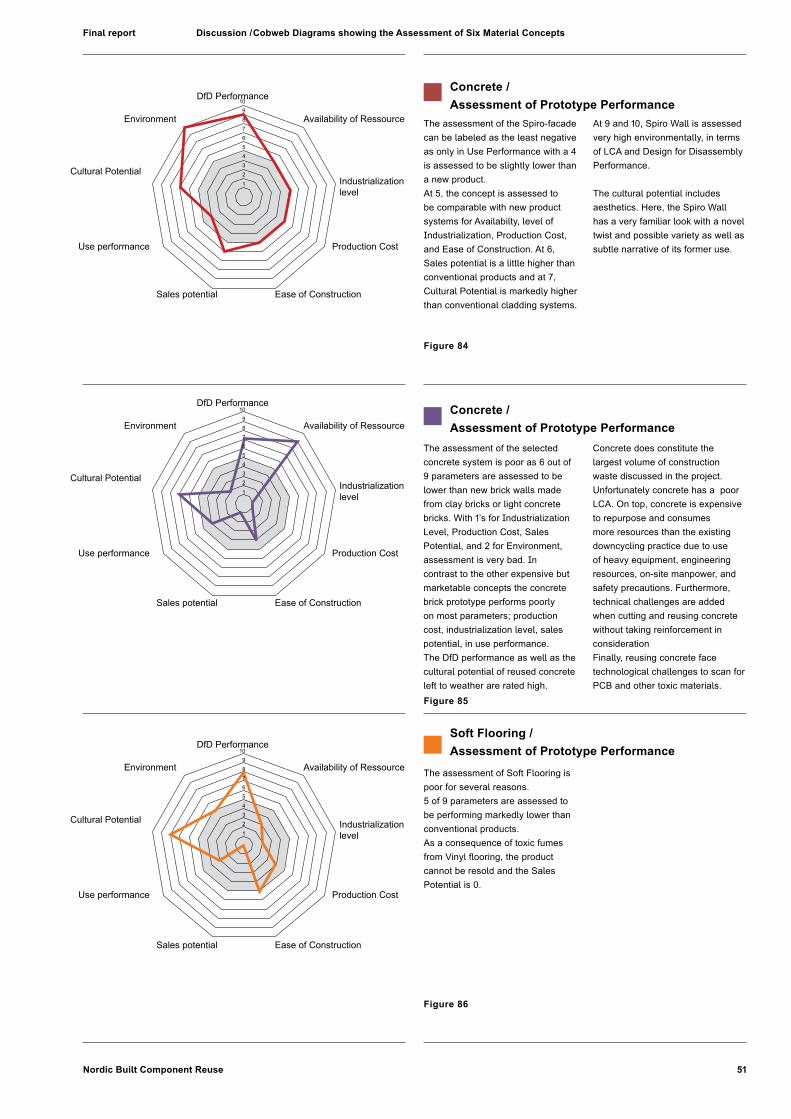
51Nordic Built Component Reuse
Final report Cobweb Diagrams showing the Assessment of Six Material Concepts
The assessment of the selected concrete system is poor as 6 out of 9 parameters are assessed to be lower than new brick walls made from clay bricks or light concrete bricks. With 1’s for Industrialization Level, Production Cost, Sales Potential, and 2 for Environment, assessment is very bad. In contrast to the other expensive but marketable concepts the concrete brick prototype performs poorly on most parameters; production cost, industrialization level, sales potential, in use performance. The DfD performance as well as the cultural potential of reused concrete left to weather are rated high.
Concrete does constitute the largest volume of construction waste discussed in the project. Unfortunately concrete has a poor LCA. On top, concrete is expensive to repurpose and consumes more resources than the existing downcycling practice due to use of heavy equipment, engineering resources, on-site manpower, and safety precautions. Furthermore, technical challenges are added when cutting and reusing concrete without taking reinforcement in consideration Finally, reusing concrete face technological challenges to scan for PCB and other toxic materials.
Concrete / Assessment of Prototype Performance
The assessment of the Spiro-facade can be labeled as the least negative as only in Use Performance with a 4 is assessed to be slightly lower than a new product.At 5, the concept is assessed to be comparable with new product systems for Availabilty, level of Industrialization, Production Cost, and Ease of Construction. At 6, Sales potential is a little higher than conventional products and at 7, Cultural Potential is markedly higher than conventional cladding systems.
At 9 and 10, Spiro Wall is assessed very high environmentally, in terms of LCA and Design for Disassembly Performance.
The cultural potential includes aesthetics. Here, the Spiro Wall has a very familiar look with a novel twist and possible variety as well as subtle narrative of its former use.
The assessment of Soft Flooring is poor for several reasons. 5 of 9 parameters are assessed to be performing markedly lower than conventional products.As a consequence of toxic fumes from Vinyl flooring, the product cannot be resold and the Sales Potential is 0.
Concrete / Assessment of Prototype Performance
Soft Flooring / Assessment of Prototype Performance
The assessment of the Spiro-facade can be labeled as the least negative as only in Use Performance with a 4 is assessed to be slightly lower than a new product.At 5, the concept is assessed to be comparable with new product sys-tems for Availabilty, level of Industri-alization, Production Cost, and Ease of Construction. At 6, Sales potential is a little higher than conventional products and at 7, Cultural Potential is markedly higher than conventional cladding systems.
At 9 and 10, Spiro Wall is assessed very high environmentally, in terms of LCA and Design for Disassembly Performance.
The cultural potential includes aesthetics. Here, the Spiro Wall has a very familiar look with a novel twist and possible variety as well as subtle narrative of its former use.
The assessment of the selected concrete system is less than promising. 6 out of 9 parameters are assessed to be lower than new brick walls made from clay bricks or light concrete bricks. In fact, with 1’s for Industrialization Level, Production Cost, Sales Potential, and 2 for Environment. In contrast to the expensive but still marketable concepts the concrete brick prototype performs poorly on most parameters; production cost, industrialization level, sales potential, in use performance. The luxury potential does not exist. Since concrete constitutes the largest volume of construction
waste. Unfortunately it has proven the only poor LCA. On top, concrete has proved expensive to repurpose and consumes more resources than the existing downcycling practice as the envisioned dismantling of concrete demands excessive use of heavy equipment, engineering resources, on-site manpower, and safety precautions. Furthermore, the reuse of concrete without taking reinforcement in consideration brings additional technical challenges to the concepts. Finally, reusing concrete face technological challenges to scan for PCB and other toxic materials.
The assessment of Soft Flooring is poor for several reasons. 5 of 9 parameters are assessed to be performing markedly lower than conventional products.Noting that the Sales Potential is 0. This is a consequence of toxic fumes from Vinyl flooring.
V:\Nordic Built\_04_Grafik\Rapport_AM\Diagram-materialer 2AM.indd
Sales potential Ease of Construction
Availability of Ressource
Production CostUse performance
Cultural Potential
DfD Performance
Environment
Sales potential Ease of Construction
Availability of Ressource
Industrialization level
Production CostUse performance
Cultural Potential
DfD Performance
Environment
1
23456789
10
1
23456789
10
Availability of Ressource
Production CostUse performance
Cultural Potential
DfD Performance
Environment
1
23456789
10
Sales potential Ease of Construction
Concrete / Assessment of Prototype Performance
Concrete / Assessment of Prototype Performance
Soft Flooring / Assessment of Prototype Performance
Industrialization level
Industrialization level
15Nordic Built Component Reuse 20160905
Final report Discussion /
Figure 84
Figure 85
Figure 86

52 Nordic Built Component Reuse
Final report Discussion
Utilization of project resultsPhysical results, in terms of concept prototypes as well as methods and experiences gained through the process, are utilized by the project partners, Genbyg, Vandkunsten, and Asplan Viak.
Utilization of results by GenbygFor Genbyg, the project has been a direct catalyst for new projects and services and thus influential to the business development.
- The Nordic Wall concept prototype is currently in production at the Genbyg workshop and for sale on their web shop.
- 20.000m2 of a variety of wood reuse concepts have been commissioned for Copenhagen Towers.1
- The pantile façade concept has been commissioned and is manufactured for a new built.2
- the company has established an architecture studio and hired architects to work with design and manufacture of component repurpose design.
- The company has also established a 1000 m2 workshop, directly derived from the project.
Genbyg uses project results to accelerate the expansion of their products span. The NBCR-concepts can be described as 'prepared system components' in between objects and components resold in the condition as sourced, and those used in furniture.
Table 87: Existing and expanded business models of Genbyg
1 Lendager Architects for Norman Foster Architects2 Both comissioned by Danish design firm Lendager Architects
Genbyg’s position when engaged in commissions has furthermore been strengthened by the experience obtained during the project:
- Knowledge of barriers regarding logistics as well as the documentation and assessment of workflows enable Genbyg to more accurately calculate the price of customized commissions as well as suggest the environmental impact of reuse in particular cases..
- Furthermore, the project has shown that it is not simple to compare new components with repurposed components with neither clients nor contractors. It is a new practice and mutual insights and experiences must be gained across the sector for its full implementation. In the future, strategies for sourcing and repurposing components in projects will require early involvement by Genbyg
Utilization of results by VandkunstenWhile material concepts may prove applicable in future Vandkunsten projects, the most direct utilization of results for the architecture studio is at present using the analytical tool as well as the documentation of workflows relating to the LCAs.
• The analytical tool can be used with clients to analyse existing structures for reuse of resources of cultural, economic, and environmental value.
• The concepts have been developed further by students in the project “Recycling Station – design strategies for material reuse” made under supervision by Vandkunsten. Construction drawings as well as numerous visualizations from the project are important tools when bidding for projects and developing ideas for clients.
• The LCA work further strengthens Vandkunsten’s aim to provide evidence for the economical, the environmental, and the social sustainability of
Existing: - Small scale manufacture of one of-furniture design from repurposed materials for design pieces and individual furniture. Sold via web-shop and commissioned in custom dimensions. - Resells 'fun' objects and material or components as sourced, in web-shop
New business/service: - Custom-made large-volume system products such as walls or facades. - Design and production contracts via own independent design studio. - Prototypes and manufacture in expanded workshop
Figure 87 Existing and expanded business models of Genbyg
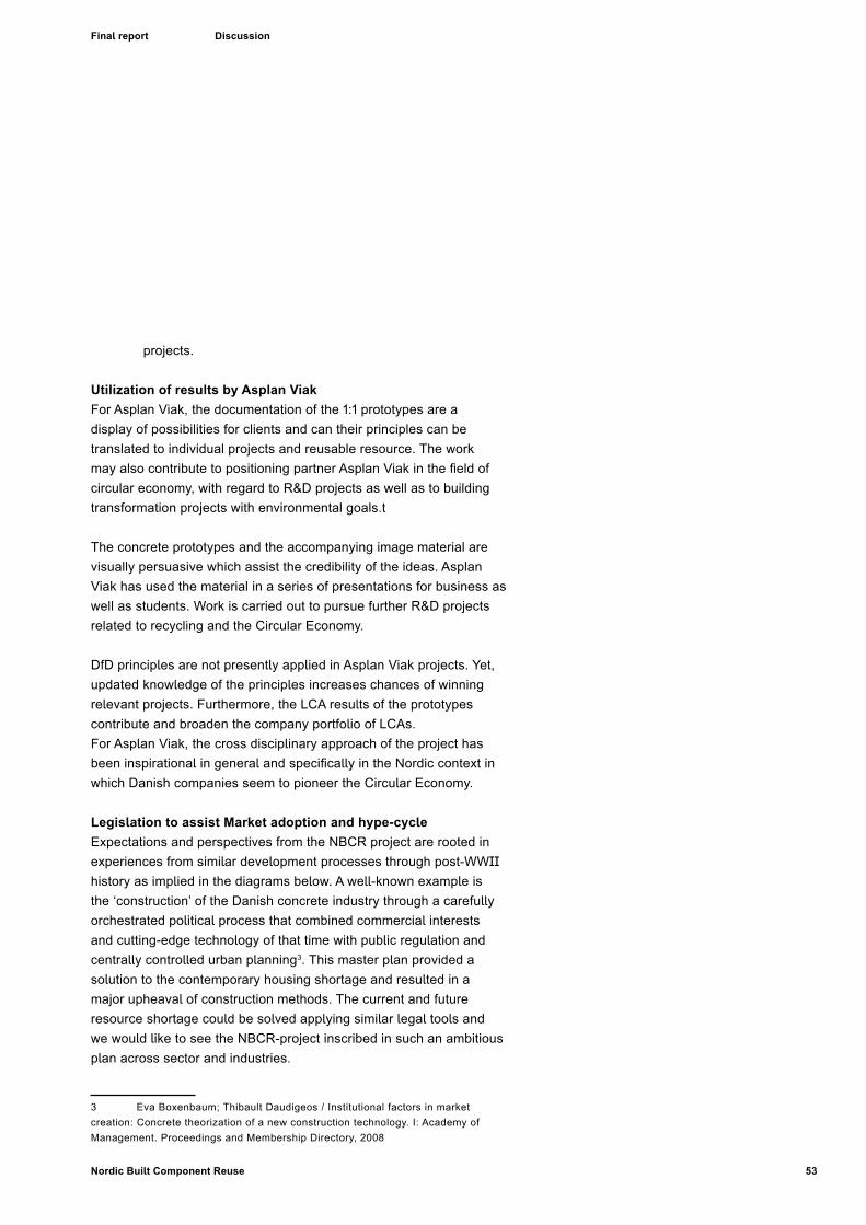
53Nordic Built Component Reuse
Final report Discussion
projects.
Utilization of results by Asplan ViakFor Asplan Viak, the documentation of the 1:1 prototypes are a display of possibilities for clients and can their principles can be translated to individual projects and reusable resource. The work may also contribute to positioning partner Asplan Viak in the field of circular economy, with regard to R&D projects as well as to building transformation projects with environmental goals.t
The concrete prototypes and the accompanying image material are visually persuasive which assist the credibility of the ideas. Asplan Viak has used the material in a series of presentations for business as well as students. Work is carried out to pursue further R&D projects related to recycling and the Circular Economy.
DfD principles are not presently applied in Asplan Viak projects. Yet, updated knowledge of the principles increases chances of winning relevant projects. Furthermore, the LCA results of the prototypes contribute and broaden the company portfolio of LCAs.For Asplan Viak, the cross disciplinary approach of the project has been inspirational in general and specifically in the Nordic context in which Danish companies seem to pioneer the Circular Economy.
Legislation to assist Market adoption and hype-cycleExpectations and perspectives from the NBCR project are rooted in experiences from similar development processes through post-WWII history as implied in the diagrams below. A well-known example is the ‘construction’ of the Danish concrete industry through a carefully orchestrated political process that combined commercial interests and cutting-edge technology of that time with public regulation and centrally controlled urban planning3. This master plan provided a solution to the contemporary housing shortage and resulted in a major upheaval of construction methods. The current and future resource shortage could be solved applying similar legal tools and we would like to see the NBCR-project inscribed in such an ambitious plan across sector and industries.
3 Eva Boxenbaum; Thibault Daudigeos / Institutional factors in market creation: Concrete theorization of a new construction technology. I: Academy of Management. Proceedings and Membership Directory, 2008

54 Nordic Built Component Reuse
Final report Discussion
Figure 88 Adoption cycle diagram, adapted from Gartner, www.gartner.com
Figure 89 ‘Hype-cycle’ diagram, adapted from Gartner, www.gartner.com
Evolving of the projectThe development period of the NBCR project was approximately 18 months. This short-term perspective resulted in an efficient and intensive collaboration process. The explorative and making-based nature of the project has led to great enthusiasm all through the team.
The project evolved roughly according to the set schedule. The overall structure of the development process remained intact throughout the period, whereas some of the titles of the milestones changed. In autumn 2014 an opportunity for exhibiting in Oslo appeared, which on the one hand speeded up the process before the event, but heavy logistics caused some exhaustion on the other.
The workshop production of mock-ups evolved unexpectedly efficient. The team received help from sympathizers who volunteered to track down waste material or kindly offered their consultancy, and from talented architect students whose semester curriculum included reuse strategies.

55Nordic Built Component Reuse
Final report Discussion
In in December 2014 – January 2015 an internal design competition was held at Vandkunsten in order to gain a maximum of design ideas. 18 entries were assessed by the NBCR-team as a jury. Two entries were selected for realisation as full-scale prototypes. Both were metal concepts (acoustic panels from waste cable trays and façade shingles from waste thin plate metal), while four others received honourable mention but not executed as prototypes.
Problems, failures, risks and shortcomingsFeasibilityCommercial feasibility was the highest risk of the project. In fact only the the Nordic Wall has developed into a marketable product at Genbyg’s web-shop . One reason is that a stable delivery is hard to maintain. This challenge has led to a new business model that is based on custom made to order and system principles rather than fixed products.
FailureIn creative and innovative processes that have shaped this project, successes emerge from numerous accounts of trial and error - and failures are inevitable. Hence, some concepts failed and were ruled out by poor LCAs or cost-evaluations, others by the environmental evaluation even though they lived up to other quality parameters for becoming a marketable product.
LogisticsHandling the odd size waste materials and managing the workshop logistics proved a challenge for the team. Between Vandkunsten and Genbyg, there was not the necessary available workshop space. We hired a shipping container and fitted it with tools as a workshop venue. It quickly became too small and much time and effort was spent on logistics.
Technology Technology has been an unexpected challenge as we were unaware of which technologies that could enable a feasible production line; they may not exist yet; or have not yet been applied for the purpose. In such cases, we envisioned and illustrated possible technological scenarios that may be pursued in further projects.
Assessing commercial potential related to repurposing and upcycling waste components is significantly dependent on the time perspective. As an upcoming branch of the building materials market expectations are closely related to the development scenario for regulations and technological innovation. The NBCR-project unfolds under premature market conditions and thus aims more for preparing the market than for exploiting an existing potential.
The assessment scheme planned to be developed with qualitative and quantitative input proved too complex and difficult to compile. Evaluation based on data such as the flowcharts and LCAs were simple but the assessment of cultural or commercial potentials have so many unknown factors. The initial assessment matrix and descriptive cobweb diagrams are included nevertheless to enable
- See flowcharts and background information in the appendix in the LCA section
Fig 90-91 —Two versions of failed concept due to environmental reasons; vinyl flooring repurposed as façade panel.

56 Nordic Built Component Reuse
Final report Discussion
input and discussion of this point with actors in the sector.
Based on the experience of the team, a series of technological visions were created that combine existing technologies with our context of repurposing building materials. Naïve as a ‘Slabcutterbot’ might appear (imagine the mandolin slicer tool from your kitchen drawer sized to slice concrete slabs on site),
While working on the prototypes it became clear that numerous operations necessary for practicing reuse could be carried out more efficient and economically viable if supported by technologies. Some exist today, others need further development or transfer from other industries. Therefore, as a part of the project, the team have spent some work on defining and visualizing the anticipated technology. On the following pages are a few visions that we have illustrated: the Slab Cutter Bot that slices concrete elements on the demolitions site, the sorting plant, the scanner of toxins in building materials, and a close-up of the wood sorting and cleaning factory.
Dissemination of ResultsThe material nature of the project has allowed it to be displayed and discussed at exhibitions and conferences in Scandinavia and the United States.
The prototypes themselves have been exhibited in Oslo, and at different venues in Copenhagen and are presently on display at the Vandkunsten office. A list of dissemination activities can be found in the appendix.
Basis for further developmentWhat’s next:To establish an actual practice of reuse, more demonstration projects will be required, initially on an experimental basis, later as full-scale implementation in construction projects. An eventual successful full-scale implementation will stand out as a proof-of-concept test, leading to more similar projects in which the know-how will become refined. (See the adoption cycle diagram). We see the project as an agent that contributes to preparing the ground for a market development through inspiration and discussions of initial demonstration models.
Demonstration Strategies for certified buildingsApplying the NBCR-strategies with clients can enable projects to achieve certifications with DfD demands.
The next step is demonstrating the results of the project in practice.The physical prototypes, images, and the illustrations have been discussed in a number of seminars as will be listed in the appendix. These concrete suggestions of future scenarios and LCAs have led to engaging major public clients in a dialogue to find a small building project where the NBCR-products and ideas can be demonstrated.
The products, prototypes, ideas, and methods will now be deployed in up-coming assignments. Each partner in the team will have individual approaches and opportunities to continue parts of the project - deepening particular aspects or widening the scope, whether it is demonstration projects, ordinary commissions, decoration purposes, improved sales infrastructure or analytical tools. It is likely that partners of the team will collaborate in the future.
We have projects in the pipeline and will be able to suggest site-specific material concepts in future bids and competitions.
The NBCR-project point forward to new projects: For extra validity and aid the implementation of reused material components, LCA models need further development. The market for LCAs is growing, yet LCA models do not anticipate a reuse cycle prior to incineration. Nor do LCA incorporate the impact of aesthetics on the lifetime of buildings and compo-nents. This means that LCAs for new materials sometimes will achieve better results than they ought to.
Benchmarking perspectivesA way of phasing in standards pre-regulatory is through industrial certification systems such as DGNB-DK or BREEAM-NOR. The certification systems set even very ambitious targets for single parameters, and provide reliable assessment procedures. In a proof-of-concept scenario one or more certification system is very likely to be involved. The certification systems constitute important tools for establishing benchmarks for what is possible. They are, however, not capable of influencing the wider market.
Technological perspectivesWhile working on the prototypes it became obvious that many operations necessary for practicing reuse could be carried out much more efficient and economically viable if supported by the right technology. The team has defined and visualized a number of technological scenarios and discussed

57Nordic Built Component Reuse
Final report
them with stakeholders. The ability to defining the problem might be of equally importance as mastering the skills for engineering the solutions.
Educational perspectivesDuring the initial research, which involved interviews with a number of professionals in Danish demolishing industry, it appeared that no post-high-school education has demolition as part of its training curriculum . Skilled demolition as a precondition for reuse is dependent on industry initiatives, which are in turn dependent on harsh market mechanisms. As opposed to industries such as agriculture, pharmaceutical or energy, the demolition profession has not yet been able to nurture its innovation from institutional research. Through our exploration of the diverse and complicated conditions applicable for high-level reuse, the idea of a regular master-level education evoked - e.g. a 'Demolition Engineer', a specialty uniting central aspects; environmental hygiene, safety, reversible construction, instrumental skills and logistics. As a start, technical schools and universities might begin to integrate knowledge on demolition in the respective disciplines, and thereby creating the basis for a faster innovation.
Current marketWith a voluminous home market for building renovation there is a strong potential for developing methods, tools and knowledge, which might in turn spread to markets outside the Nordic region. The traditional architectural design process operates on the background of a product market with a stable stock of familiar products in well-known dimensions and of reliable qualities. With a practice of reusing components from one building to the next there is a need for more flexible methods for designing the geometry and describing the construction work. At present, reselling and reprocessing reused building components is a market niche, mostly valid in the private sector. It might be rapidly scaled up when methods of industrialization are employed.
Project conclusionThrough design and construction of 25 scale 1:1 prototypes of material concepts

58 Nordic Built Component Reuse
Final report Discussion / vision
4. F
urth
er d
own
the
line
1. L
oadi
ng a
rea
2. S
cann
ing
mod
ule
3. A
utom
ated
mat
eria
l cle
nsin
g pr
oces
ses
Fig
97 W
ood
Reu
se P
lant
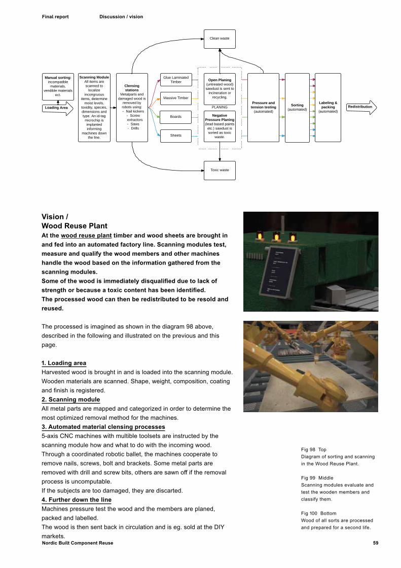
59Nordic Built Component Reuse
Final report Discussion / vision
Fig 98 TopDiagram of sorting and scanning in the Wood Reuse Plant.
Fig 99 MiddleScanning modules evaluate and test the wooden members and classify them.
Fig 100 BottomWood of all sorts are processed and prepared for a second life.
Vision / Wood Reuse PlantAt the wood reuse plant timber and wood sheets are brought in and fed into an automated factory line. Scanning modules test, measure and qualify the wood members and other machines handle the wood based on the information gathered from the scanning modules. Some of the wood is immediately disqualified due to lack of strength or because a toxic content has been identified.The processed wood can then be redistributed to be resold and reused.
The processed is imagined as shown in the diagram 98 above, described in the following and illustrated on the previous and this page.
1. Loading areaHarvested wood is brought in and is loaded into the scanning module.Wooden materials are scanned. Shape, weight, composition, coating and finish is registered.2. Scanning moduleAll metal parts are mapped and categorized in order to determine the most optimized removal method for the machines.3. Automated material clensing processes5-axis CNC machines with multible toolsets are instructed by the scanning module how and what to do with the incoming wood.Through a coordinated robotic ballet, the machines cooperate to remove nails, screws, bolt and brackets. Some metal parts are removed with drill and screw bits, others are sawn off if the removal process is uncomputable.If the subjects are too damaged, they are discarted.4. Further down the lineMachines pressure test the wood and the members are planed, packed and labelled.The wood is then sent back in circulation and is eg. sold at the DIY markets.

60 Nordic Built Component Reuse
Final report DiscussionDiscussion / vision
Vision / The Slab Cutter Bot Slices concrete on the spotThe Slab Cutter Bot is our vision of a transportable machine that slices concrete slabs into sections, blocks or tiles and stacks them, ready for transportation to be reassebled on a construction site nearby.
This machine already exists in stationary setups. It seems like an easy development to mount a diamond wheel saw bridge on wheels and add a stacking mechanism at the end of the conveyer. The “Slab cutter bot vision”, is thus a transportable machine that cuts concrete element walls into sections, blocks or tiles and stacks them, ready to transport and reuse on a nearby building project. This machine would make it possible to minimize labour and transport associated with the refactoring process. E
xist
ing
conc
rete
cut
ing
tech
nolo
gy.
Sta
te o
f the
Art
Faca
de fr
om c
ut c
oncr
ete
bloc
ks.
Fig
93 /
Vis
ion
of th
e S
lab
Cut
ter
Bot
Fig
92
ROBOTS ON THE BUILDING SITEPrecast concrete panels are dismantled, cut on the site and reused as tiles.
FACTORY FOR WOOD REUSEWood of all sorts and sizes are analysed, handled and sorted by robots.
FACTORY FOR METAL REUSEMetal of all sorts and sizes are analysed, handled and sorted by robots.
OBSOLETE CONCRETE BUILDING

61Nordic Built Component Reuse
Final report Conclusion
for walls and facades, and parallel design sessions suggesting the concepts in specific contexts, it was found that selected components currently defined as waste, could be transformed into high quality architectural design. It was concluded in three of four conducted LCA evaluations that in 4 out of 5 cases repurposing components impact climate and environment significantly less than with use of new components. Unfortunately, cost connected with rehabilitation processes often exceed the price of new products, which is mainly due to the high degree of human labour. Narrow niches in the current market for customized material components does however show opportunities for a long-term development towards a more widespread reuse of waste components and development of new technology to automate processes.
As the project challenges the regimes of current regulations and market conditions, numerous obstacles and dilemmas have been revealed, including:
o A technological gap, where a mutual dependency exists between the critical demand for secondary products and the invention of more advanced demolition tools.
o A technological challenge in documenting compliance with current critical limits for toxins in waste as well as technical quality.
o A cultural gap, where the aesthetics of wear and tear challenge normal expectations towards buildings’ appearance.’
o LCAs are difficult to obtain in the field of reuse because of the numerous variables and the difficulties in documenting the exact processes.
The above obstacles disregarded, novel architectural, technological and commercial potential results from the resource-preserving strategies, including compositional and material qualities obtained through increased construction tolerances and ornamental motifs from the assembly systems.
The LCA results are based on accurate measurements and documentations of processes. They show that the life cycle of all materials but concrete has a lower CO2 footprint than using novel materials.
Concrete While the LCAs are interesting, the cross disciplinary collaboration for obtaining the data can be concluded a necessary premise for the developing useful and comparable LCAs.
From the feedback we have received in displaying and discussing the prototypes, it can also be concluded that material prototypes has a strong impact on visualizing subjects in building culture and practice.
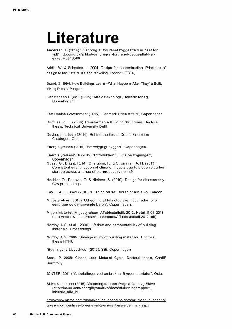
62 Nordic Built Component Reuse
Final report
Literature Andersen, U (2014) ” Genbrug af forurenet byggeaffald er gået for
vidt” http://ing.dk/artikel/genbrug-af-forurenet-byggeaffald-er-gaaet-vidt-16580
Addis, W. & Schouten, J. 2004. Design for deconstruction. Principles of design to facilitate reuse and recycling. London: CIRIA,
Brand, S. 1994: How Buildings Learn –What Happens After They’re Built, Viking Press / Penguin
Christensen,H (ed.) (1998) “Affaldsteknologi”, Teknisk forlag, Copenhagen.
The Danish Government (2015) ”Danmark Uden Affald”, Copenhagen.
Durmisevic, E. (2006) Transformable Building Structures, Doctoral thesis, Technical University Delft
Devlieger, L (ed.) (2014) ”Behind the Green Door”, Exhibition Catalogue, Oslo.
Energistyrelsen (2015) ”Bæredygtigt byggeri”, Copenhagen.
Energistyrelsen/SBi (2015) ”Introduktion til LCA på bygninger”, Copenhagen.
Guest, G., Bright, R. M., Cherubini, F., & Strømman, A. H. (2013). Consistent quantification of climate impacts due to biogenic carbon storage across a range of bio-product systems9
Hechler, O., Popovic, O. & Nielsen, S. (2010). Design for disassembly. C25 proceedings.
Kay, T. & J. Essex (2010) “Pushing reuse” Bioregional/Salvo, London
Miljøstyrelsen (2015) ”Udredning af teknologiske muligheder for at genbruge og genanvende beton”, Copenhagen.
Miljøministeriet, Miljøstyrelsen, Affaldsstatistik 2012, Notat 11.06.2013 (http://mst.dk/media/mst/Attachments/Affaldsstatistik2012.pdf)
Nordby, A.S. et al. (2006) Lifetime and demountability of building materials. Proceedings
Nordby, A.S. 2009. Salvageability of building materials. Doctoral thesis NTNU
”Bygningens Livscyklus” (2015), SBi, Copenhagen
Sassi, P. 2008: Closed Loop Material Cycle, Doctoral thesis, Cardiff University
SINTEF (2014) ”Anbefalinger ved ombruk av Byggematerialer”, Oslo.
Skive Kommune (2015) Afslutningsrapport Projekt Genbyg Skive. (http://issuu.com/energibyenskive/docs/afslutningsrapport_inklusiv_alle_bi)
http://www.kpmg.com/global/en/issuesandinsights/articlespublications/taxes-and-incentives-for-renewable-energy/pages/denmark.aspx
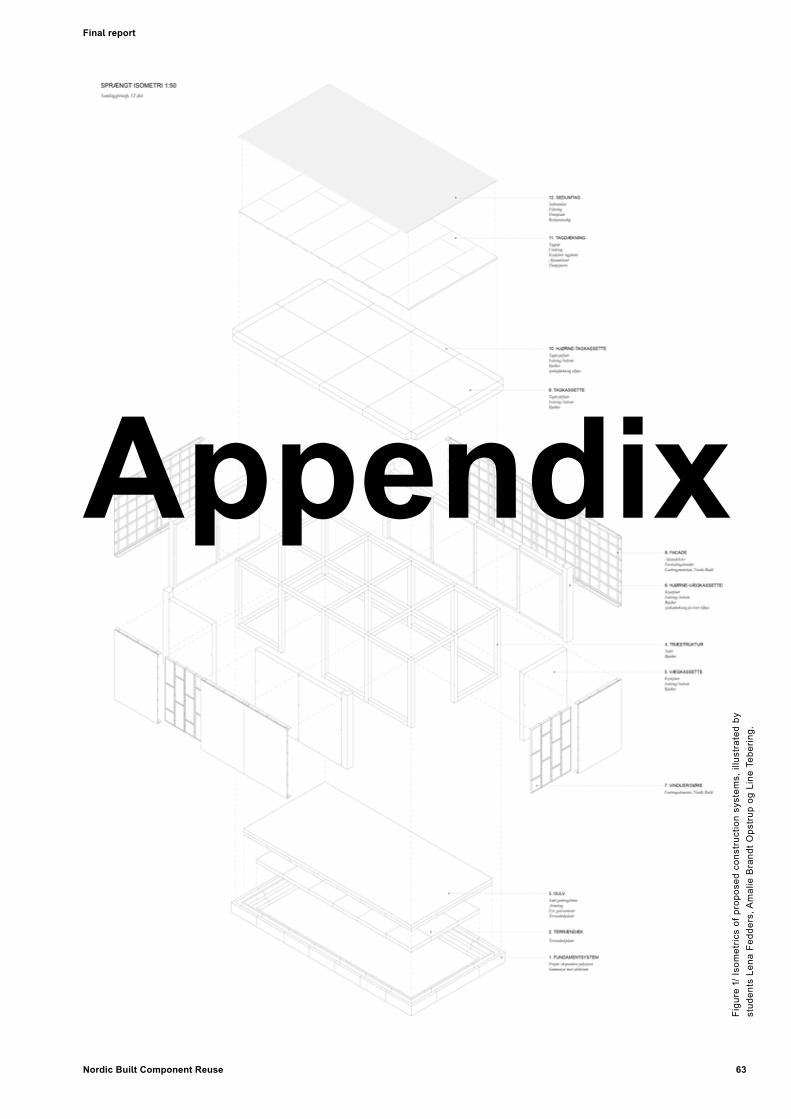
63Nordic Built Component Reuse
Final report
Figu
re 1
/ Iso
met
rics
of p
ropo
sed
cons
truc
tion
syst
ems,
illu
stra
ted
by
stud
ents
Len
a Fe
dder
s, A
mal
ie B
rand
t Ops
trup
og
Line
Teb
erin
g.
Appendix

64 Nordic Built Component Reuse
Appendix
InterviewsList of Industry experts/ dates for first round of interviews
Dissemination
Charts for material lifecyclesConcrete bricks/claddingCladding using roof tilesGlazed window facadeInterior wall from reused wooden floorsSpiro Wall / Facade cladding from metal ventilation ducts
61
61
62
73
Content in Appendix
Figure 2 > NBCR at LevVel exhibition DogA, Oslo November 2014. See the further list of dissemination on the following page.
Content

65Nordic Built Component Reuse
Appendix
Industry experts / dates for first round of interviews
o Tscherning A/S: Demolition contractor. Peter Hansen, Head of Department. 14.08.2014
o RGS 90 A/S: Waste handling and recycling company. Michael Christiansen, Sales Manager. 21.08.2014
o Genbyg A/S: Reseller of reused building materials and components. Jesper Holmberg, co-owner and not part of the project. 18.05.15
o HJ Hansen: Scrap Dealer, : Morten Widtfeldt, Manager.28/04/2015
o Glasfakta: Expertise and counselling on glass. www.glasfakta.dk. Carl Axel Lorentzen, Engineer and co-owner.17/04/2015
o Glarmester Aage Larsen. www.danmarkssydligsteglarmester.dk Morten Larsen, Owner 15/06/2015
o Diatool Aps Diamantværktøj. www.diatool.dk Kaj Andersen, Owner, Structural Engineer. June 2015
o Danish Waste Solutions. www.danws.dk/ Ole Hjelmar, Chemical Engineer, Co-owner. June 2015
o RoboCluster Innovationsnetværk, September 1, 2015
o Additional valuable feedback has been obtained during dissemination at seminars and conferences.
Dissemination Visions and results of the project have been exhibited and presented in lectures and magazines on numerous occasions.
Publications and articlesKleis, B., ”Forskningspraktik i detaljen”, BYG – Bæredygtigt Byggeri #2 2016 s26-29 (4pp), 26-29, Arkitektens Forlag, København
Larsen, M.S., ”Ny arkitektur af gamle bygningsdele”, BYG – Bæredygtigt Byggeri #2 2016 s30-32 (3pp), Arkitektens Forlag, København
Madsen, U.S et al (ed), Idekatalog over nye designstrategier for genanvendelse, KADK/Cinark – Center for Industriel Arkitektur, København, 2016 (40 pp)
Nordby, A.S. and Sørnes, K.; Fra skrap til skatter. Arkitektur N nr. 2-15
Nordby, A.S.; Ombruk - et bærekraftig førstevalg? Byggfakta, September 2016
Asplan Viak's Webzine the customer magazine "Kvartalet": www.asplanviak.no/aktuelt/2016/05/31/ombruk-byggematerialer/ www.asplanviak.no/temaer/kampanjer/kvartalet/kvartalet-nr-2-2016-vugge-til-vugge/baerekraftige-materialer/
ExhibitionsThree prototypes and a number of visualisations were exhibited at the exhibition Lev Vel in Oslo at Dog A, November 2014.
One prototype and a series of posters were exhibited at the Reuse Conference in Skive, Denmark, February 2015.
Prototypes were exhibited at the Trends & Traditions Fair at Lokomotivværkstedet in Copenhagen, March 2015.
Exhibition of mock-ups and lecture presentation at Building Green Fair, Copenhagen October 25-28 2015.
Lectures
Project ideas and work-in-progress results were presented at Nordic Built Kick-off meeting in Copenhagen November 20th 2014.
Project ideas and work-in-progress results were presented at research seminar at Royal Danish Academy of Fines Arts, Schools of Architecture, Design, and Conservation (KADK), Copenhagen, November 28th 2014.
Project ideas and work-in-progress results have been presented at internal seminar at Vandkunsten with professor David Leatherbarrow, Pennsylvania University and professor Ali Malkawi, Harvard University, December 1st 2014.
Presentation at Harvard Center for Green Buildings and Cities 2015 Fall Conference‘Sustainability in Scandinavia’, Boston, November 3-6 2015.
Presentation at ICSA-conference, Everyday Tectonics Session, Guymaraes Portugal July 27-29 2015.
Project ideas and work-in-progress results were presented in lecture at NTNU in Trondheim, October 2014.
Project ideas and work-in-progress results were presented at the Norwegian building waste seminar in Oslo, January 2016
Project ideas and work-in-progress results were presented in «Pecha Kucha» night at NTNU in Trondheim, March 2016
Project ideas and work-in-progress results were presented at Svartlamon-workshop in Trondheim, September 2016
Project ideas and work-in-progress results were presented in seminar on Circular Economy, arranged by OREEC in Oslo, September 2016.

66 Nordic Built Component Reuse
Appendix
Visualization of use in context
Visualizations of use of concrete brick cladding in context
Figu
re 4
/ V
isua
lizat
ion
of c
once
ptFi
gure
3 /
Vis
ualiz
atio
n by
stu
dent
s Le
na F
edde
rs, A
mal
ie B
rand
t Ops
trup
og
Line
Teb
erin
g.

67Nordic Built Component Reuse
Appendix Figure 6 / Flowchart for the prototype bricks made from concrete
— Figure 5Concrete bricks made from concrete slabs

68 Nordic Built Component Reuse
AppendixCO
MPL
ETE
CHA
RT O
F M
ATER
IAL
LIFE
CYCL
ECO
NCR
ETE
BRIC
K W
ALL
IND
SATS
FAKT
A
Som
e pa
ram
etre
s ha
ve b
een
used
from
the
rese
arch
pap
er b
y D
anis
h M
iljøs
tyre
lsen
“Udr
ed-
ning
af t
ekno
logi
ske
mul
ighe
der f
or a
t gen
brug
e og
gen
anve
nde
beto
n”. T
hese
val
ues
are
mar
ked
by (*
) sin
ce th
ey re
pres
ent t
he b
est e
stim
ate
whe
n no
oth
er s
ourc
e ha
s be
en a
vaila
ble.
Estim
ate
of s
tand
ard
prod
uctio
n of
con
cret
e el
emen
ts:
CO2-
foda
ftry
kket
ved
pro
dukt
ion
af e
t eur
opæ
isk
genn
emsn
itlig
t let
beto
nele
men
t med
en
dens
itet p
å 1,
95 to
n pe
r m3
og e
n ty
kkel
se p
å 15
cm
er e
stim
eret
til 5
2 kg
CO
2-æ
kviv
alen
ter
per m
2 (B
eton
elem
ent-
Fore
ning
en, 2
014)
.
2) D
rillin
g fo
r dis
man
tling
anc
hors
- 3
0 m
inut
esD
rillin
g 6
hole
s x
5 m
inut
es =
30
min
utes
with
ham
mer
Dril
l 850
W
Pow
er u
sage
= 4
25 W
att
3) C
uttin
g of
join
ts -
60 m
inut
es (c
uttin
g 2
met
res
at 3
0 cm
thic
k pa
nels
)Co
ncre
te w
ith d
iam
ond
tip b
lade
s fo
r cut
ting
out w
all p
anel
s: 1
9 kW
h, e
nerg
y us
age:
19k
Wh/
m2
+ us
age
of d
iam
ond
tip b
lade
s ha
s to
be
take
n in
to a
ccou
nt.
(it’s
all v
ery
expe
nsiv
e eq
uipm
ent,
the
port
able
saw
is a
bout
DK
200.
000)
4) C
rane
lift
- 15
min
utes
?Po
wer
usa
ge b
y lif
ting
977
kg o
f con
cret
eA
n es
timat
e of
15
min
s. fo
r lift
ing
1m2
of c
oncr
ete
pane
l of e
xist
ing
build
ing
is a
gen
eral
isat
ion
of th
e va
lue.
5) R
insi
ng, s
andb
last
ing
/ hig
h pr
essu
re w
ashi
ng -
15 m
inut
esRi
nsin
g sh
ould
be
done
at m
inim
um 3
000
PSI/2
07 b
ar14
kW
h en
gine
= 3
,5 k
Wh
Wat
er u
sage
is 1
9 lit
res/
min
ute
= 28
5 lit
res/
m2
(Dat
a in
put f
rom
Con
cret
e po
wer
was
hers
)
6) C
uttin
g on
flat
bed
benc
h, m
echa
nica
l - 1
20 m
inut
es
Cutt
ing
conc
rete
pan
els
into
blo
cks
of 2
0 cm
wid
th (4
cut
s of
1 m
)Fl
atbe
d co
ncre
te s
aw u
ses
40 k
Hw
= 8
0 kW
h
cutt
ing
time
is v
ery
depe
nden
t on
the
elem
ents
.6
m c
uttin
g (3
0 cm
thic
knes
s) w
ill b
e ab
out 3
hou
rs
(dat
a in
put f
rom
Dan
ish
conc
rete
cut
ting
com
pany
Dia
tool
). Is
ther
e a
gene
ric v
alue
for c
ost/
ener
gy g
oing
into
pro
duct
ion
of th
ese
blad
es?
7) S
tack
ing,
sto
ring
- 10
min
utes
/m2
Pow
er u
sage
for c
rane
lift
aft
er c
uttin
g/rin
sing
pro
cess
- is
this
a g
ener
ic v
alue
?
8) T
rans
port
atio
n - 5
min
utes
/m2
Onl
y 1
tran
spor
taio
n in
put,
sinc
e sc
enar
io is
pro
cess
ing
conc
rete
on-
site
Tr
ansp
orta
tion
is 1
del
iver
y to
new
bui
ldin
g si
te fr
om d
econ
stru
ctio
n si
te.
9) B
rickw
ork
/ tili
ng, n
ew m
orta
r, m
anua
l - 2
0 m
inut
es/m
25
met
res
of w
all e
dges
hav
e to
be
laid
with
new
mor
tar.
Est.
time
is to
tal f
or b
rickw
ork/
layi
ng m
orta
r/m
ount
ing
wal
l tie
s.
Diffi
cult
to e
stim
ate
at -
is th
is a
real
istic
am
ount
of t
ime
goin
g in
to e
rect
ing
this
type
of c
on-
cret
e br
ickw
ork
wal
l?
10) N
ew w
all t
ies,
stai
nles
s st
eel -
0 m
inut
es10
new
wal
l tie
s pr
. m2
Wei
ghin
g ab
out 5
0 g
x 10
= 5
00 g
ram
23
4
56
78
910
150
%10
%
Bas
is o
f cal
cula
tion
TOTA
L W
ORK
ING
HO
URS
INCL
UD
ED IN
PRO
DU
CTI
ON
OF
1 M
2
250
min
utes
of e
ffici
ent p
rodu
ctio
n tim
e +
5 m
inut
es o
f tra
nspo
rtat
ion
+ 20
min
utes
of m
ount
ing
= 27
5 m
inut
es e
mbo
died
wor
k ho
urs
pr. m
2
Pow
er u
sage
: 205
,85
kW (d
rillin
g, 2
x c
uttin
g, ri
nsin
g) To
this
sou
ld b
e ad
ded
pow
er c
omsu
mpt
ion
of:
2 x
cran
e lif
t + 1
tran
spor
tatio
n by
truc
k (g
ener
ic v
alue
s?)
Figure 7 / Complete chart of material lifecycle for Concrete brick wall
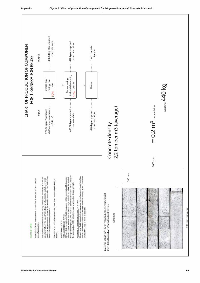
69Nordic Built Component Reuse
Appendix
CHA
RT O
F PR
OD
UC
TIO
N O
F CO
MPO
NEN
TFO
R 1.
GEN
ERAT
ION
REU
SE
Reve
rse
pro-
cesi
ng, o
n-si
te
Repr
oces
sing
, in
dust
rial s
cena
rio,
on-s
ite
Reus
e1
m2 c
oncr
ete
faca
de44
0 kg
repu
rpos
edco
ncre
te b
ricks
440
kg re
purp
osed
conc
rete
bric
ks48
8,88
kg
re-c
laim
edco
ncre
te s
labs
488,
88 k
g of
re-c
laim
edco
ncre
te s
labs
977,
77 k
g of
“raw
mat
e-ria
l”, c
oncr
ete
elem
ents
=
0,44
m3
outp
utin
put
Conc
rete
den
sity
2,2
ton
per m
3 (a
vera
ge)
Mat
eria
l usa
ge fo
r 1m
2 of r
ecyc
led
conc
rete
bric
k w
all
Calc
ulat
ed b
ased
on
a ‘fa
cade
udsn
it’ a
s th
is:
1000
mm
200
mm
200
mm
thic
knes
s
1000
mm
= 0,
2 m
3 co
ncre
te b
ricks
wei
ghin
g 44
0 kg
WO
RKIN
G H
OU
RS
We
have
dis
cuss
ed a
nd e
stim
ated
the
amou
nt o
f min
utes
of l
abor
for e
ach
step
of p
rodu
ctio
n.
Ass
umpt
ions
abo
ut w
aste
in re
clai
min
g pr
oces
s an
d pr
oces
sing
is b
ased
on
calc
ulat
ions
from
the
repo
rt “U
dred
ning
af t
ekno
logi
ske
mul
ighe
der f
or a
t ge
nbru
ge o
g ge
nanv
ende
bet
on” b
y Te
knol
ogis
k In
stitu
t for
the
Dan
ish
Gov
-er
nmen
tal d
epar
tmen
t Milj
østy
rels
en.
The
estim
ate
is s
till r
athe
r pes
sim
istic
abo
ut ti
me
cons
umpt
ion
to k
eep
it re
alis
tic.
WA
STE
PRO
DU
CTI
ON
1)
Re-
clai
min
g st
age
- 50%
(*)
50%
was
te is
the
estim
ate
that
the
conc
rete
will
be
un-r
ecla
imab
le b
ecua
se
of n
atur
al w
ear a
nd te
ar, i
rrep
arab
le d
amag
e an
d off
-cut
s w
hen
dism
antle
d,
tran
spor
t dam
agin
g et
c. T
his
valu
e w
ill b
e dr
astic
ally
low
ered
whe
n D
esig
n fo
r D
esco
nstr
uctio
n (D
fD) i
s im
plem
ente
d as
a s
tand
ard
desi
gn p
rinci
ple.
6) C
uttin
g to
sta
ndar
d di
men
sion
s - 1
0 %
was
te
We
estim
ate
that
the
recl
aim
ing
proc
ess
earli
er o
n ha
s so
rted
out
a lo
t of t
he
irrep
arab
le c
oncr
ete
slab
s an
d th
e re
gist
ratio
n/te
chno
logy
asp
ect m
inim
izes
w
aste
at t
his
step
as
muc
h as
pos
sibl
e.
10%
50%
Figure 8 / Chart of production of component for 1st generation reuse/ Concrete brick wall

70 Nordic Built Component Reuse
Appendix
Conceptual sketch
Conceptual sketch/ for glazed window facade
— Figure 9Visualization of the concept used in a project. Work from “Recycling Station – design strategies for material reuse” by architecture students Lena Fedders, Amalie Brandt Opstrup og Line Tebering, Royal Danish Academy of Fine Arts, School of Architecture, Settlement Ecology and Tectonics
— Figure 10Conceptual sketch

71Nordic Built Component Reuse
Appendix
Dire
ct re
use
pote
ntia
l
Min
ig, s
and,
m
iner
als
EOL,
mat
eria
lre
cove
ry
Floa
tgla
sspr
oduc
tion
Alum
iniu
m
Seal
ants
Repr
oces
sing
,Do
wnc
yclin
g 1
Reus
eRe
vers
epr
oces
sing
Recy
clin
g,al
tern
ate
scen
ario
s
Cutti
ng
Tran
spor
tatio
n
Was
teW
aste
Dism
antli
ng,
man
ual w
ith m
ech.
to
ols
Dism
antli
ng,
man
ual w
ith m
ech.
ha
nd to
ols
Built
-in
com
pone
nts
intr
ansl
ucen
t wal
ls
Tran
spor
tatio
n
Mou
ntin
g, m
anua
lw
ith m
ech.
han
d to
ols
Woo
d fr
ame
Stee
l bra
cket
s
Dism
antli
ng,
man
ual w
ith m
ech.
ha
nd to
ols
Rins
ing,
wat
er/
alco
hol
Sort
ing
dim
ensi
ons,
qu
ality
Refin
ing
of
win
dow
ele
men
t
Surf
ace
treat
men
t
Stac
king
, sto
ring
Tran
spor
tatio
n
Dire
ct re
use
scen
ario
Downcycling scenario
Cutti
ng e
dges
,se
mi a
utom
atic
Sepa
ratin
g co
mpo
nent
s
Cutti
ng to
fixe
dde
min
sion
s,
sem
i aut
omat
ic
Rins
ing,
wat
er/
alco
hol
Asse
mbl
ing
of
shee
ts b
y gl
uein
g
— Figure 12Glass facade made from used glazed windows
Figure 11 / Flowchart for the prototype glazed window facade

72 Nordic Built Component Reuse
Appendix Figure 13 / Complete chart of material lifecyclw for glazed window facade
Ref
inin
g of
w
indo
w e
lem
ent
Woo
d fr
ame
Ste
el b
rack
ets
Mou
ntin
g, m
anua
l
Sur
face
tr
eatm
ent
Sor
ting
dim
ensi
on, q
ualit
y
COM
PLET
E CH
ART
OF
MAT
ERIA
L LI
FECY
CLE
INSU
LATE
D W
IND
OW
SIN
DSA
TSFA
KTA
Calc
ulat
ion
base
d on
pro
cess
ing
of 4
win
dow
s (5
0x50
cm
) = 1
m2
of n
ew w
indo
w s
urfa
ce
1) D
ism
antli
ng w
indo
w e
lem
ents
- 5
min
utes
Dis
man
tling
fram
e4x
4 sc
rew
s =
sec.
s of
dril
ling
DeW
alt m
achi
ne 1
4,4
V25
0 W
att
Carr
ying
4 w
indo
ws
to c
ar
2)Tr
ansp
orta
tion
- 2 m
inut
esfx
. 25
km b
y lo
rry,
Mer
cede
s Sp
rinte
r 316
CD
I 163
HK
(typ
ical
in C
ph)
Max
. loa
d 1.
400
kgO
wn
wei
ght:
2214
kg
Die
sel c
onsu
mpt
ion
whe
n em
tpy:
12,
6 km
/l, w
hen
fully
load
ed, m
aybe
8 k
m/l
Ener
gycl
ass
F
4) S
ortin
g ac
cord
ing
to d
imen
sion
s an
d qu
ality
- 2
min
utes
i.e U
nloa
ding
from
truc
k, c
arry
ing
to s
tora
ge, c
atal
ogin
g
5) R
efini
ng o
f win
dow
ele
men
t - 4
x (3
x 1
min
utes
) = 1
2 m
inut
es o
f cut
ting
Win
dow
s ar
e cu
t on
12 s
ides
by
tabl
e sa
w to
cle
an u
p su
rfac
es a
nd re
-dim
ensi
on/r
e-sh
ape
the
elem
ent.
Tabl
e sa
w is
:Pa
olon
i P4
5M
ain
Mot
or P
ower
: 5,5
kW
h12
min
utes
of c
uttin
g =
1,1
kW
6) S
urfa
ce tr
eatm
ent -
4 x
(1 x
2 x
2) m
inut
es =
16
min
utes
The
fram
es c
an b
e tr
eate
d w
ith a
num
ber o
f oli,
pai
nts,
laqu
er o
r sta
ins
For t
he p
roto
type
we
used
sta
ins
(a w
alnu
t col
ored
pig
men
t), w
ater
base
d pr
oduc
tan
d se
aled
with
2 la
yers
of l
inse
ed o
il 7)
Sta
ckin
g an
d st
orin
g - 4
min
utes
W
e es
timat
e a
smal
l am
ount
of w
ork
effor
t goe
s in
to th
e lo
gist
ics
of th
e w
indo
ws,
cata
logi
ng, d
escr
ibin
g th
e (t
o w
ebsi
te) a
nd m
akin
g th
e sa
le w
ith c
usto
mer
s.
8) T
rans
port
atio
n - 6
min
utes
We
estim
ate
a hi
gher
ratio
of t
rans
port
atio
n tim
e at
this
poi
nt b
ecau
se th
e nu
mbe
r of s
alva
ged
com
pone
nts
will
be
low
er.
9) M
ount
ing
- 20
min
utes
The
prot
otyp
e so
lutio
n w
e pr
opos
e he
re is
a 1
m2
(4 w
indo
ws
50 x
50
cm)
Prep
arat
ion
of 4
x 1
m b
atte
ns (l
ægt
er) f
or n
ew fr
ame,
10
min
utes
10) W
ood
fram
e, s
teel
bra
cket
sA
re th
ere
gene
ric m
ater
ial v
alue
s fo
r the
se?
WA
STE
PRO
DU
CTI
ON
3) W
e es
timat
e th
at a
bout
20%
(1 o
ut o
f eve
ry 5
win
dow
s) a
re e
ither
pun
ctur
ed o
r th
e w
ood
is in
too
bad
cond
ition
to re
proc
ess.
TOTA
L W
ORK
ING
HO
URS
INCL
UD
ED IN
PRO
DU
CTI
ON
OF
1 M
2
49 m
inut
es o
f effi
cien
t pro
duct
ion
time
+ 8
min
utes
of t
rans
port
atio
n +
20 m
inut
es
of m
ount
ing
= 77
min
utes
em
bodi
ed w
ork
hour
s pr
. m2
Bas
is o
f cal
cula
tion
12
84
56
7
910
320
%

73Nordic Built Component Reuse
Appendix Figure 14 / Chart of production of component for 1st generation reuse/ glazed window facade
CHA
RT O
F PR
OD
UC
TIO
N O
F CO
MPO
NEN
TFO
R 1.
GEN
ERAT
ION
REU
SE
Reve
rse
pro-
cesi
ng, o
n-si
te
Repr
oces
sing
, in
dust
rial s
cena
rio,
on-s
ite
Reus
e1
m2 w
indo
w fa
cade
1m2 re
purp
osed
win
dow
fram
es
1 m
2 repu
rpos
edw
indo
w fr
ames
1 m
2 re-c
laim
edw
indo
ws
1 m
2 of r
e-cl
aim
edw
indo
ws
1,25
m2 o
f “ra
w m
ater
ial”,
us
ed in
sula
ted
win
dow
s
outp
utin
put
Win
dow
sM
ater
ial u
sage
for 1
m2 o
f rec
ycle
d w
indo
w fa
cade
i.e. 4
re-c
laim
ed in
sula
ted
win
dow
s, ge
neric
exa
mpl
e of
set
up
for c
alcu
latio
n pu
rpos
e, n
ot to
be
rega
rded
as
desi
gn p
ropo
sal
1000
mm
1000
mm
= 1m
2 w
indo
w fa
cade
WO
RKIN
G H
OU
RS
Base
d on
est
imat
es p
rett
y m
uch
the
sam
e w
ay a
s w
ith
the
New
Nor
dic
Wal
l.
0%20%

74 Nordic Built Component Reuse
Appendix Visualization of use of wood wall in context
Visualization of use in context— Figure 15Visualization of the concept ’New Nordic Wall’

75Nordic Built Component Reuse
Appendix Figire 16 / Flowchart for the prototype Indoor wall made from used interior wood
Recy
clin
g,
alte
rnat
e sc
enar
ios
EOL,
mat
eria
lre
cove
ry
Door
bla
des
(Use
, 1. G
ener
atio
n)
Palle
t boa
rds
Glu
eing
Dem
ount
ing
Sort
ing
Tran
spor
tatio
n
Was
teW
aste
Stee
l fitt
ing
Pain
t
Plas
tic la
min
ate
Tran
spor
tatio
n
Prep
arat
ion
by
dism
ount
ing
Cutti
ng u
p
Drilli
ng h
oles
Repl
acin
g br
oken
pie
ces
Rins
ing
Bund
ling,
sta
ckin
g
Mou
ntin
ggl
ue/s
crew
s
Grin
ding
Bund
elin
g,st
acki
ng, s
torin
g
Bund
elin
g,st
acki
ng, s
torin
g
Mou
ntin
g, m
anua
l, w
ith m
ech.
han
d to
ols
Dism
antli
ng,
man
ual,
with
m
ech.
han
d to
ols
Sort
ing,
man
ual
Tran
spor
tatio
n
Disc
ardi
ng s
cena
rio
Dire
ct re
use
loop
sce
nario
— Figure 17Indoor wall made from used interior wood

76 Nordic Built Component Reuse
Appendix Figure 18 / Complete chart of material lifecycle/ Wall element of old doors/ the ’New Nordic Wall’
Dem
ount
ing
Tran
spor
tatio
nB
unde
ling,
stac
king
, sto
ring
Mou
ntin
g, m
anua
l,w
ith m
ech.
han
dto
ols
COM
PLET
E CH
ART
OF
MAT
ERIA
L LI
FECY
CLE
WA
LL E
LEM
ENT
OF
OLD
DO
ORS
THE
“NEW
NO
RDIC
WA
LL”
IND
SATS
FAKT
A
The
inpu
t dat
a ha
s be
en s
tand
ariz
ed (a
ll 4
prot
otyp
es) f
or c
erta
in p
roce
ss s
teps
i.e
. tra
nspo
rtat
ion,
sam
e ca
r, dr
ivin
g di
stan
ce, u
nits
etc
.
2) D
emou
ntin
g w
oode
n flo
or b
oard
s, w
oode
n do
ors,
pane
ls e
tc. -
5 m
inut
esA
n es
timat
e fo
r rem
oval
of a
3) S
ortin
g an
d ha
ndlin
g -
2 m
inut
esLo
adin
g tr
uck
4) T
rans
port
atio
n - 2
min
utes
fx. 2
5 km
by
lorr
y, M
erce
des
Sprin
ter 3
16 C
DI 1
63 H
K (t
ypic
al in
Cph
)M
ax. l
oad
1.40
0 kg
Ow
n w
eigh
t: 22
14 k
gD
iese
l con
sum
ptio
n w
hen
emtp
y: 1
2,6
km/l,
whe
n fu
lly lo
aded
, may
be 8
km
/lEn
ergy
clas
s F
5) P
repa
ratio
n by
dis
mou
ntin
g (P
rodu
ktio
nsfo
rber
edel
se) -
2 m
inut
esU
nloa
ding
truc
k, s
ettin
g up
mac
hine
s fo
r cut
ting
6) C
uttin
g up
- 12
min
utes
Tabl
e sa
w is
:Pa
olon
i P4
5M
ain
Mot
or P
ower
: 5,5
kW
h12
min
utes
of c
uttin
g =
1,1
kW
7) D
rillin
g ho
les
- 2 m
inut
es
8) M
ount
ing
glue
/ sc
rew
s - 1
0 m
inut
es
9) G
rindi
ng &
sur
face
trea
tmen
t - 5
+ 2
min
utes
10) B
unde
ling/
stac
king
/sto
ring
- 1 m
inut
eIn
wor
ksho
p an
d st
orag
e, o
ff-si
te
11) T
rans
port
atio
n - 2
min
utes
12) B
unde
ling/
stac
king
/sto
ring
- 2 m
inut
esU
nloa
ding
truc
k, s
torin
g on
-site
13) M
ount
ing,
man
ual -
20
min
utes
pr.
1m2
of in
stal
ling
the
wal
l.W
ork
time
estim
ate
is a
n av
erag
e va
lue
of: l
iftin
g, m
ount
ing
elem
ents
toge
ther
(w
hich
is d
one
real
ly fa
st),
adju
stin
g to
doo
r fra
mes
, cei
ling,
out
er w
alls
etc
.
WA
STE
PRO
DU
CTI
ON
1) T
he N
ew N
ordi
c W
all c
an c
onsi
st o
f rec
ycle
d pa
rts
from
mos
t woo
d-ba
sed
prod
ucts
. The
aim
is to
gat
her u
p an
d re
use
all t
he o
dd b
its a
nd in
this
way
the
aim
is to
cre
ate
a ne
w a
esth
ic fr
om a
ll sc
ratc
h.
Sinc
e th
e so
urce
of t
his
mat
eria
l cou
ld c
ome
from
any
woo
d re
late
d pr
oduc
t, as
w
ell a
s gi
ven
the
natu
ral s
tate
of t
he m
ater
ial,
we
will
est
imat
e th
at 3
3% o
f the
co
llect
ed w
ood
will
go
to c
ut-o
ffs a
nd/o
r det
erio
rate
d w
aste
(rot
and
dam
age)
TOTA
L W
ORK
ING
HO
URS
INCL
UD
ED IN
PRO
DU
CTI
ON
OF
1 M
2
43 m
inut
es o
f effi
cien
t pro
duct
ion
time
+ 4
min
utes
of t
rans
port
atio
n +
20 m
in-
utes
of m
ount
ing
= 67
min
utes
em
bodi
ed w
ork
hour
s pr
. m2
1 10
2 5 11
3 620
%
12134 7
89
33%
Bas
is o
f cal
cula
tion

77Nordic Built Component Reuse
Appendix
CHA
RT O
F PR
OD
UC
TIO
N O
F CO
MPO
NEN
TFO
R 1.
GEN
ERAT
ION
REU
SE
Reve
rse
pro-
cesi
ng, o
n-si
te
Repr
oces
sing
, in
dust
rial s
cena
rio,
on-s
ite
Reus
e1
m2 in
terio
r wal
l45
kg
repu
rpos
edw
ood
prod
ucts
45 k
g re
purp
osed
woo
d pr
oduc
ts56
,25
kg re
-cla
imed
woo
d pr
oduc
ts
56,2
5 kg
of r
e-cl
aim
edw
ood
prod
ucts
84,3
8 kg
of “
raw
mat
eria
l”,
used
doo
rs, fl
oor b
oard
s, pa
nels
etc
.
outp
utin
put
New
Nor
dic
Wal
l - e
lem
ents
Mat
eria
l usa
ge fo
r 1m
2 of r
ecyc
led
inte
rior w
all
1000
mm
1000
mm
100
mm
400
mm
abou
t 6 b
lock
s
= 1m
2 in
terio
r wal
l
wei
ghin
g (a
bout
) 45
kg
WO
RKIN
G H
OU
RS
Tim
e us
age
in m
inut
es is
est
imat
ed fo
r pro
duct
ion
of
1 m
2 of
New
Nor
dic
inte
rior w
all m
ade
from
var
ious
so
urce
s of
scr
ap w
ood.
The
re a
re m
any
varia
bles
in th
e so
urce
s, w
here
wer
e do
es th
e do
ors/
floor
s co
me
from
, w
hat i
s th
e co
nditi
on (i
s th
ere
a lo
t of w
aste
initi
ally
in
the
harv
estin
g pr
oces
s?) w
hat a
re th
e qu
antit
ies?
Thi
s w
ill v
ary
each
tim
e yo
u ha
rves
t. M
aybe
in p
artic
ular
w
hen
it co
mes
to w
ood,
sin
ce it
’s a
We
have
dis
cuss
ed th
e pa
ram
etre
s an
d m
ade
assu
mp-
tions
abo
ut q
uant
ities
as
wel
l as
gene
ral s
tead
y w
ork
flow
in w
ood
woo
rkin
g. T
ime
cons
umpt
ion
may
be
dras
tical
ly re
duce
d w
hen
harv
estin
g is
bet
ter o
rgan
ised
, tr
ansp
orta
tion
and
stor
ing
is c
oord
inat
ed a
nd h
andl
ed
on a
larg
er s
cale
and
so
on.
We
have
des
crib
ed th
e fo
llow
ing
prod
uctio
n as
a g
en-
eral
est
imat
ed a
cces
s to
the
mat
eria
ls.
20%
33%
Figure 19 / Chart of production of component for 1st generation reuse/ Indoor wall made from used interior wood

78 Nordic Built Component Reuse
Appendix
Visualization of use in context
Illustrations of facade cladding made from rolled ventilation ducts / Visualization of use in context
Fgur
e 21
/ V
isua
lizat
ion
of c
once
pt il
lust
rate
d as
the
faca
de o
f an
old
Vand
kuns
ten
proj
ect
Fgur
e 20
/ V
isua
lizat
ion
by s
tude
nts
Lena
Fed
ders
, Am
alie
Bra
ndt O
pstr
up o
g Li
ne T
eber
ing.

79Nordic Built Component Reuse
Appendix
— Figure 23Facade cladding made from rolled ventilation ducts
Dire
ct re
use
pote
ntia
l
Stee
l, ge
neric
Recy
clin
g,
alte
rnat
e sc
enar
ios
EOL,
mat
eria
lre
cove
ry
Zinc
pla
ting,
ge
neric
Rollin
g, fo
ldin
g
Bund
ling,
sto
ring
Tran
spor
tatio
n
Dism
antli
ng,
man
ual w
ith m
ech.
to
ols
Sort
ing
Tran
spor
tatio
n
Rins
ing,
wat
er
high
-pre
ssur
e w
ashi
ng,
mec
hani
cal
Dryi
ng, n
atur
al
Rollin
g,
mec
hani
cal
Cutti
ng, m
echa
nica
l
Fold
ing
(end
s),
mec
hani
cal
Bund
ling,
sta
ckin
g,
stor
ing
Was
teW
aste
Was
te
Tran
spor
tatio
n
Mou
ntin
g, m
anua
l w
ith m
ech.
han
d to
ols
Dism
antli
ng,
man
ual w
ith
mec
h. h
and
tool
s
Sort
ing,
man
ual
Rins
ing,
wat
er
high
-pre
ssur
e w
ashi
ng,
mec
hani
cal
Dryi
ng, n
atur
al
Bund
ling,
sta
ckin
g
Disc
ardi
ng s
cena
rio
Dire
ct re
use
loop
sce
nario
Figure 22 / Flowchart for the prototype Facade cladding made from rolled ventilation ducts

80 Nordic Built Component Reuse
Appendix Figure 24 / Overview of material life cycle for Facade cladding made from rolled ventilation ductsIN
DSA
TSFA
KTA
Estim
ate
of 5
x 1
040
cm S
piro
duc
t (ne
eded
for 1
m2
faca
de) V
ario
us d
iam
eter
s
WEI
GH
T/LE
NG
HT
RATI
OFx
Duc
t dia
met
er: 1
2,5
cm
wei
ght p
r 100
cm
: 185
7,14
gra
m
2) D
ism
antli
ng/m
ount
ing
by m
ech.
tool
s - 1
0 m
inut
es2x
2 se
c. u
nfas
teni
ng o
f scr
ews,
DeW
alt m
achi
ne 1
4,4
V25
0 W
att
3) S
ortin
g is
don
e by
man
ual l
abor
- 2
min
utes
no e
nerg
y co
nsum
ptio
nw
hen
take
n do
ne, a
lot o
f the
rem
aini
ng p
artic
les
in th
e du
ct w
ill/c
an b
e sh
edm
aybe
obs
olet
ing
the
rinsi
ng p
roce
ss?
4) T
rans
port
atio
n - 2
min
utes
fx. 2
5 km
by
lorr
y, M
erce
des
Sprin
ter 3
16 C
DI 1
63 H
K (t
ypic
al in
Cph
)M
ax. l
oad
1.40
0 kg
Ow
n w
eigh
t: 22
14 k
gD
iese
l con
sum
ptio
n w
hen
emtp
y: 1
2,6
km/l,
whe
n fu
lly lo
aded
, may
be 8
km
/l En
er-
gycl
ass
F
5) N
ot s
ure
whe
ther
this
pro
cedu
re is
nes
cess
ary,
but
info
is: -
5 m
inut
esda
ta fr
om h
ttp:
//cl
ena.
dk/k
s-st
atio
n%C3
%A
6r
5 se
c. h
igh
pres
sure
rins
ing
5,5
kWh
3x40
0 V
50 h
z
if ch
emic
al is
nee
ded,
then
this
cou
ld d
o pe
rhap
s:
http
://w
ww
.rkim
iljo.
dk/m
edia
/file
s/D
atab
lad_
NY/
UD
EN/8
1600
1%20
-%20
2803
11.p
df
6) P
ress
ing/
flatt
enin
g - i
nfo
from
dan
vals
.dk
- 5 m
inut
esD
one
by h
ydra
lic p
ress
10 to
ns p
ress
,30
sec
. pre
ss
1,5
kWh
7) C
uttin
g to
sta
ndar
dize
d di
men
sion
s - 2
min
utes
Don
e by
ste
el s
heet
she
arin
g m
achi
ne/c
utte
r5
sec.
1,
5 kW
hCu
t-off
s w
ill b
e ab
out 2
0%
8) F
oldi
ng (e
nds)
- 8
min
utes
Don
e by
Hyd
raul
ic b
endi
ng m
achi
ne o
r pre
ss b
rake
s20
sec
. eac
h en
d of
eac
h du
ct.
3 kW
h
9) B
unde
ling/
stac
king
/sto
ring
- 1 m
inut
eIn
wor
ksho
p an
d st
orag
e, o
ff-si
te
10) M
ount
ing
man
ual w
ith m
ech.
han
d to
ols
- 15
min
utes
In w
orks
hop
and
stor
age,
off-
site
WA
STE
PRO
DU
CTI
ON
1) W
e es
timat
e 40
% w
aste
in th
e in
itial
recl
aim
ing
proc
ess
(tea
r fro
m a
ging
and
be
nded
duc
ts, c
orne
rs e
tc.)
TOTA
L W
ORK
ING
HO
URS
INCL
UD
ED IN
PRO
DU
CTI
ON
OF
1 M
2
33 m
inut
es o
f effi
cien
t pro
duct
ion
time
+ 4
min
utes
of t
rans
port
atio
n +
15 m
inut
es
23
4
3
3
56
10
5 &
7
78
9115
%
Bas
is o
f cal
cula
tion
20%
Pre
ssin
g
OVE
RVIE
W O
F M
ATER
IAL
LIFE
CYCL
ESP
IRO
WA
LL C
LAD
DIN
G
of m
ount
ing
= 52
min
utes
em
bodi
ed w
ork
hour
s pr
. m2

81Nordic Built Component Reuse
Appendix
WO
RKIN
G H
OU
RS
We
have
dis
cuss
ed a
nd e
stim
ated
the
amou
nt o
f min
-ut
es o
f lab
or fo
r eac
h st
ep o
f pro
duct
ion.
The
estim
ate
is b
ased
on
aver
age
valu
es b
etw
een
info
fr
om a
Dan
ish
man
ufac
tor o
f she
et m
etal
pro
duct
s an
d a
estim
ate
of in
crea
sed
prod
uctio
n effi
cien
cy b
y an
up-
scal
ed p
rodu
ctio
n flo
w w
hen
the
recl
aim
ing
stra
tegi
es
are
real
ised
.
Exam
ple:
7)
Fol
ding
(end
s) -
Don
e by
Hyd
raul
ic b
endi
ng m
achi
ne o
r pre
ss b
rake
s20
sec
. for
eac
h en
d of
eac
h du
ct =
360
sec
.3
kWh
1 pe
rson
wor
king
8 m
inut
es h
andl
ing
9 du
cts
(1m
2 ), op
erat
ing
the
mac
hine
and
pac
king
them
on
a pa
llet o
r si
mila
r ste
ps.
The
estim
ate
is s
till r
athe
r pes
sim
istic
abo
ut ti
me
con-
sum
ptio
n to
kee
p it
real
istic
.
CHA
RT O
F PR
OD
UC
TIO
N O
F CO
MPO
NEN
TFO
R 1.
GEN
ERAT
ION
REU
SE
150
200
70 c
m
0,10
5 m
2 flat
tend
duc
t wei
ghin
g 13
00 g
15 c
m
ove
rlapp
ing
40 m
m
Mat
eria
l usg
e fo
r 1m
2 of S
piro
duc
t fac
ade
clad
ding
Calc
ulat
ed b
ased
on
a ‘fa
cade
udsn
it’ a
s th
is:
= 1,
2688
m2
flatt
end
duct
s co
verin
g m
2 fa
cade
wei
ghin
g 15
,71
kg
Org
. duc
t dim
ensi
on:
Wid
th, fl
atte
nd d
uct:
Ø 1
25 m
m
150
mm
Ø 1
60 m
m
200
mm
Ø 2
00 m
m
250
mm
Ø 2
50 m
m
310
mm
310
310
1040
mm
1040
mm
250
Reve
rse
pro-
cesi
ng, o
n-si
te
Repr
oces
sing
, in
dust
rial s
cena
rio,
on-s
ite
Reus
e1
m2 S
piro
faca
de1,
2688
m2 fl
atte
nd
spiro
duc
ts 1
5,71
kg
15,7
1 kg
spi
ro
duct
s19
,64
kg s
piro
du
cts
19,6
4 kg
spi
ro
duct
s23
,11
kg
spiro
du
cts
outp
utin
tput
20%
15%
Figure 25 / Facade cladding made from rolled ventilation ducts / Chart of production of component for 1st generation reuse

82 Nordic Built Component Reuse
Appendix
Rendering of concept
Visualization of use of roof tile cladding
Figi
re 2
7 / V
isua
lizat
ion
of a
ver
sion
of t
he c
once
ptFi
gure
26
/ Vis
ualiz
atio
n by
stu
dent
s Le
na F
edde
rs, A
mal
ie B
rand
t Ops
trup
and
Lin
e Te
berin
g.

83Nordic Built Component Reuse
Appendix
— Figure 29Facade cladding made from roof tiles
Figure 28 / Flowchart for the prototype Facade cladding made from roof tiles
Dire
ct re
use
pote
ntia
l
Clay
qua
rry
Recy
clin
g,
alte
rnat
e sc
enar
ios
EOL,
mat
eria
lre
cove
ry
Mix
ing
clay
type
s,
sand
, saw
dust
Mou
ld s
hapi
ngw
ith p
ress
ure
Burn
ing
in k
iln
Qua
lity
test
ing,
st
acki
ngW
aste
Was
te
Dism
antli
ng,
man
ual b
y ha
nd
scaf
fold
ing/
ladd
er
Qua
lity
sort
ing,
m
anua
l
Stac
king
on
palle
ts
Tran
spor
tatio
nW
oode
n su
ppor
tco
nstr
uctio
n
Mou
ntin
g br
acke
ts
man
ual w
ith m
ech.
hand
tool
sBu
ndlin
g, s
torin
g
Plac
ing
tiles
in
brac
kets
, man
ual
Pant
ile ro
ofDi
sman
tling
, m
anua
l with
m
ech.
han
d to
ols
Stac
king
on
palle
ts
Grin
ding
Siev
ing
part
icle
si
zes
Terr
acot
ta g
rave
l
Was
te

84 Nordic Built Component Reuse
Appendix Figure 30 / Overview of material life cycle for Facade cladding made from roof tilesCO
MPL
ETE
CHA
RT O
F M
ATER
IAL
LIFE
CYCL
ERO
OF
TILE
WA
LL C
LAD
DIN
GIN
DSA
TSFA
KTA
LCA
-dat
a is
cal
cula
ted
for 1
m2
of ro
of ti
les
repu
rpos
ed a
s cl
addi
ng fo
r ext
erio
r wal
ls,
gard
en w
alls
, fen
cing
and
oth
er s
uch
surf
aces
. The
con
cept
is fo
r at e
asy-
to m
ount
, fa
irly
chea
p, a
esth
etic
ally
‘den
se’ w
all c
ladd
ing
whi
ch s
eals
off
mos
t rai
n an
d w
ind
if no
t all.
2) D
ism
antli
ng p
antil
es fr
om ro
of-
5 m
inut
esW
ork
is d
one
man
ually
- it’
s qu
ite e
asy
actu
ally
. The
tile
s ar
e m
ostly
laid
out
on
roof
ba
tten
s w
ith fe
w fa
sten
ing
poin
ts/s
crew
s.
We
estim
ate
that
qua
lity
sort
ing
coul
d be
don
e rig
ht a
t the
poi
nt w
hen
dism
antli
ng
the
tiles
.A
pal
let i
s pl
aced
for t
he w
hole
tile
s, an
d a
pipi
ng +
con
tain
er a
t gro
und
leve
l (or
so
met
hing
like
this
) is
set u
p fo
r the
bro
ken
ones
(abo
ut 1
0%)
3) S
tack
ing
on p
alle
ts -
1 m
inut
esTh
e til
es a
re a
lread
y ne
atly
/opt
imal
pla
ced
in p
alle
ts d
urin
g di
smou
ntin
g.
We
estim
ated
a s
mal
l am
ount
of t
ime
goes
into
han
dlin
g th
e pa
llets
on-
site
.
4) T
rans
port
atio
n (b
ack
and
fort
h) -
2 x
2 m
inut
es =
4 m
inut
esfx
. 25
km b
y lo
rry,
Mer
cede
s Sp
rinte
r 316
CD
I 163
HK
(typ
ical
in C
ph)
Max
. loa
d 1.
400
kgO
wn
wei
ght:
2214
kg
Die
sel c
onsu
mpt
ion
whe
n em
tpy:
12,
6 km
/l, w
hen
fully
load
ed, m
aybe
8 k
m/l
Ener
-gy
clas
s F
5) W
oode
n su
ppor
t con
stru
ctio
n - 5
min
utes
For m
ount
ing
the
tiles
we
expe
ct 2
row
s of
bat
tens
pr.
row
of t
iles
for h
angi
ng th
e til
es fr
om, i
.e. 1
0 pi
eces
of h
oris
onta
l bat
tens
(100
cm
) pr.
1m2.
Tim
e in
clud
es c
uttin
g ba
tten
s to
leng
ht.
5x2
sec.
fast
enin
g sc
rew
s pr
. bat
ten
x 10
bat
tens
pr.
m2,
D
eWal
t mac
hine
14,
4 V
250
Wat
tEn
ergy
con
sum
ptio
n: 6
,9 W
att p
r. m
2
6) B
rack
et p
rodu
ctio
n - n
o es
timat
e fo
r wor
k Is
ene
rgy
goin
g in
to p
rodu
ctio
n of
bra
cket
s a
gene
ric v
alue
?N
umbe
r of b
rack
ets
(sta
inle
ss s
teel
80x
15x1
,5 m
m):
36 b
rack
ets/
m2
Brac
kets
wei
gh a
bout
25
gram
= 9
00 g
sta
inle
ss s
teel
/m2
7) M
ount
ing
- 5 m
inut
es2x
2 se
c. fa
sten
ing
scre
ws
pr. t
ile x
18
tiles
pr m
2,
DeW
alt m
achi
ne 1
4,4
V25
0 W
att
Ener
gy c
onsu
mpt
ion:
5 W
att p
r. m
2
WA
STE
PRO
DU
CTI
ON
1)
Re-
clai
min
g st
age
- 50%
10%
was
te is
the
estim
ate
that
the
roof
tile
s w
ill b
e un
-rec
laim
able
bec
uase
of
natu
ral w
ear a
nd te
ar, i
rrep
arab
le d
amag
es to
cor
ners
etc
. whe
n di
sman
tled,
tran
s-po
rted
and
so
on. T
he c
once
pt w
e pr
opos
e, h
owev
er, d
oesn
’t ne
ed th
e til
es to
be
in 1
00%
per
fect
con
ditio
n w
hich
is w
hy w
e se
t a fa
rly lo
w e
stim
ate
on w
aste
in th
e in
itial
recl
aim
ing
scen
ario
.
23
24
5 7
6 7
110
%
Bas
is o
f cal
cula
tion
TOTA
L W
ORK
ING
HO
URS
INCL
UD
ED IN
PRO
DU
CTI
ON
OF
1 M
2
11 m
inut
es o
f effi
cien
t pro
duct
ion
time
+ 4
min
utes
of t
rans
port
atio
n +
5 m
inut
es o
f mou
ntin
g =
20 m
inut
es e
mbo
died
wor
k ho
urs
pr. m
2

85Nordic Built Component Reuse
Appendix
CHA
RT O
F PR
OD
UC
TIO
N O
F CO
MPO
NEN
TFO
R 1.
GEN
ERAT
ION
REU
SE
Reve
rse
pro-
cesi
ng, o
n-si
te
Repr
oces
sing
, in
dust
rial s
cena
rio,
on-s
ite
Reus
e1
m2 ro
of ti
le
wal
l cla
ddin
g43
.75
kg re
purp
osed
roof
tile
s
43.7
5 kg
repu
rpos
edro
of ti
les
43.
75 k
g re
-cla
imed
roof
tile
s
43.7
5 kg
of r
e-cl
aim
edro
of ti
les
48.6
1 kg
of “
raw
mat
eria
l”,
roof
tile
s
outp
utin
put
Mat
eria
l usa
ge ro
of ti
le w
all
5 ro
ws
of 3
.5 ti
les
= 17
.5 ti
les
each
tile
wei
ghin
g ab
out 2
500
g
1m2 o
f rec
ycle
d ro
of ti
le w
all
Calc
ulat
ed b
ased
on
a ‘fa
cade
udsn
it’ a
s th
is:
1000
mm
1000
mm
= 1
m2
roof
tile
wal
l cla
ddin
g
wei
ghin
g 43
.75
kg
WO
RKIN
G H
OU
RS
Sam
e m
ehod
of c
alcu
latio
n as
abo
ve m
entio
ned
0%10%
Figure 31 / Chart of production of component for 1st generation reuse/ Facade cladding made from roof tiles