Final Report No. 1894 by the Aircraft Accident ... · The report in the German language contains...
26
Büro für Flugunfalluntersuchungen Bureau d’enquête sur les accidents d’aviation Ufficio d’inchiesta sugli infortuni aeronautici Uffizi d'investigaziun per accidents d'aviatica Aircraft accident investigation bureau Final Report No. 1894 by the Aircraft Accident Investigation Bureau concerning the serious incident to aircraft AVRO 146-RJ100, HB-IYX operated by Crossair under flight number SWR 3513 on 13 July 2000 on the ground at Zurich-Kloten airport Bundeshaus Nord, CH-3003 Berne
-
Upload
truongkiet -
Category
Documents
-
view
212 -
download
0
Transcript of Final Report No. 1894 by the Aircraft Accident ... · The report in the German language contains...
Büro für Flugunfalluntersuchungen Bureau d’enquête sur les accidents d’aviation Ufficio d’inchiesta sugli infortuni aeronautici Uffizi d'investigaziun per accidents d'aviatica Aircraft accident investigation bureau
Final Report No. 1894
by the Aircraft Accident
Investigation Bureau
concerning the serious incident
to aircraft AVRO 146-RJ100, HB-IYX
operated by Crossair under flight number SWR 3513
on 13 July 2000
on the ground at Zurich-Kloten airport
Bundeshaus Nord, CH-3003 Berne

Final Report SWR 3513 HB-IYX
Aircraft Accident Investigation Bureau Page 1 of 25
Ursache
Der schwere Vorfall ist darauf zurückzuführen, dass das Bugfahrwerk der Maschine bei der Landung nicht parallel zur Flugzeuglängsachse ausgerichtet war. In der Folge brach das Flugzeug in der Ausrollphase nach rechts aus und verliess die Piste. Der Grund dafür konnte weder durch den Hersteller, das AAIB UK noch das BFU eindeutig ermittelt werden.

Final Report SWR 3513 HB-IYX
Aircraft Accident Investigation Bureau Page 2 of 25
Table of contents
General ____________________________________________________ 5
1 Factual Information ______________________________________ 6 1.1 History of the flight ________________________________________ 6
1.1.1 Prior history____________________________________________________________ 6 1.1.2 History of the flight ______________________________________________________ 6
1.2 Injuries to persons_________________________________________ 6 1.3 Damage to aircraft _________________________________________ 6 1.4 Other damage ____________________________________________ 6 1.5 Personnel information ______________________________________ 7
1.5.1 Commander____________________________________________________________ 7 1.5.2 Training Captain ________________________________________________________ 7 1.5.3 Copilot ________________________________________________________________ 8
1.6 Aircraft information ________________________________________ 8 1.6.1 Aircraft HB-IYX _________________________________________________________ 8 1.6.2 Landing gear ___________________________________________________________ 9
1.6.2.1 System description __________________________________________________ 9 1.6.2.2 Nose wheel steering_________________________________________________ 9
1.6.3 Mass and centre of gravity _______________________________________________ 11
1.7 Meteorological information _________________________________ 11 1.7.1 ATIS_________________________________________________________________ 11
1.8 Aids to navigation ________________________________________ 11 1.9 Communications _________________________________________ 11 1.10 Aerodrome information ____________________________________ 12 1.11 Flight recorders __________________________________________ 12
1.11.1 Cockpit voice recorder___________________________________________________ 12 1.11.2 Digital flight data recorder _______________________________________________ 12
1.12 Information on the location of the serious incident _______________ 12 1.13 Medical information _______________________________________ 12 1.14 Fire____________________________________________________ 12 1.15 Survival aspects __________________________________________ 12 1.16 Tests and research ________________________________________ 13
1.16.1 General ______________________________________________________________ 13 1.16.2 Conclusions of the UK Air Accidents Investigation Branch_______________________ 13 1.16.3 Conclusions of the aircraft manufacturer ____________________________________ 14 1.16.4 Conclusions of the nosewheel gear manufacturer _____________________________ 15
1.17 Organisational and management information ___________________ 15 1.17.1 The Crossair operator ___________________________________________________ 15
1.18 Additional information _____________________________________ 16 1.18.1 General ______________________________________________________________ 16 1.18.2 Investigation of the nosewheel tyres _______________________________________ 16 1.18.3 Investigation of the brakes _______________________________________________ 16
1.19 Useful or effective investigation techniques ____________________ 16
Final Report SWR 3513 HB-IYX
Aircraft Accident Investigation Bureau Page 3 of 25
2 Analysis _______________________________________________ 17 2.1 Technical aspects _________________________________________ 17
2.1.1 General ______________________________________________________________ 17 2.1.2 Veering of the aircraft to the left __________________________________________ 17 2.1.3 Veering of the aircraft to the right _________________________________________ 17 2.1.4 Summary _____________________________________________________________ 17
2.2 Human and operational aspects______________________________ 18 2.2.1 Analysis of flight history _________________________________________________ 18
3 Conclusions ____________________________________________ 19 3.1 Findings ________________________________________________ 19
3.1.1 Technical aspects ______________________________________________________ 19 3.1.2 Crew ________________________________________________________________ 19
3.2 Cause __________________________________________________ 19
4 Safety recommendations__________________________________ 20 4.1 Re-design of the the nosewheel gear steering valve ______________ 20
4.1.1 Safety deficit __________________________________________________________ 20 4.1.2 Safety recommendation no. 377___________________________________________ 20
4.2 Measures taken since the incident to improve air safety ___________ 21 4.2.1 Notice to Aircrew – NTA OP17 ____________________________________________ 21
5 Appendices ____________________________________________ 23 5.1 Drawings of nosewheel steering _____________________________ 23 5.2 Location of the serious incident ______________________________ 24 5.3 Pictures on the investigation of the nosewheel tyres______________ 25

Final Report SWR 3513 HB-IYX
Aircraft Accident Investigation Bureau Page 4 of 25
General information regarding this report
In accordance with the Convention on International Civil Aviation (ICAO Annexe 13), the sole purpose of the investigation of an aircraft accident or serious incident is to prevent future accidents or serious incidents. It is not the purpose of this investigation to determine blame or clarify questions of liability.
According to the Swiss Air Navigation Law, the legal assessment of aircraft accident/incident circumstances and causes is no concern of the incident investigation.
The masculine form is used in this report regardless of gender for reasons of data protection
All times in this report, unless otherwise indicated, are indicated in local time (LT) for Swit-zerland, corresponding at the time of the accident to Central European Summer Time (CEST). The relationship between LT, CEST and universal time coordinated (UTC) is as fol-lows: LT = CEST = UTC + 2 h.
The report in the German language contains the valid formulations.
The Aircraft Accident Investigation Bureau thanks the authorities and organisations for the support given to it in the course of the investigation.

Final Report SWR 3513 HB-IYX
Aircraft Accident Investigation Bureau Page 5 of 25
Final Report
Owner Kevin Limited, Mary Street, Georgetown
Operator Crossair AG, Postfach, 4002 Basel, Switzerland
Aircraft type AVRO 146-RJ 100
Country of manufacture United Kingdom of Great Britain and Northern Ireland (UK)
Registration HB-IYX
Location Zurich-Kloten Airport
Date and time 13 July 2000, 14:55 h
General
Brief description
On 13 July 2000, aircraft HB-IYX was flying under flight number SWR 3513 from Dusseldorf to Zurich. After landing on runway 14 at Zurich-Kloten airport, the crew lost control of the aircraft. It veered to the right, exited the runway and came to a stop on the grass after trav-elling approximately 250 m. No-one was injured.
Investigation
On the same day, the Swiss Aircraft Accident Investigation Bureau (AAIB) opened an investi-gation, in cooperation with the police of the canton Zurich and the airport authority.
The serious incident is attributable to the fact that the aircraft’s nosewheel was not parallel to the longitudinal axis of the aircraft. The aircraft subsequently veered to the right and ex-ited the runway. The reason for this could not be established by the manufacturer, the UK AAIB or the Swiss AAIB.

Final Report SWR 3513 HB-IYX
Aircraft Accident Investigation Bureau Page 6 of 25
1 Factual Information
1.1 History of the flight
1.1.1 Prior history
Between 1991 and 2001, according to a report by the Air Accidents Investigation Branch (AAIB), UK, there were a total of 29 serious incidents in connection with loss of control of the nosewheel gear on aircraft of the BAe 146/RJ type. There were five occurrences in the years 1991 and 1995. The other 24 incidents oc-curred between 2000 and 2001. In six incidents, aircraft of the operator involved in the present serious incident were involved.
In most of the 29 known incidents, the aircraft veered to the left. Aircraft veered to the right in four cases.
1.1.2 History of the flight
On 13 July 2000, aircraft HB-IYX was flying from Dusseldorf back to Zurich under flight number SWR 3513. On this scheduled flight, the commander was being monitored by one of the airline’s training captains for purposes of route introduc-tion. The latter was sitting on the jump seat in the cockpit. The pilot flying to Zu-rich was the copilot. Flight SWR 3513 was radar vectored by air traffic control and cleared for an ILS approach on runway 14. The aircraft was prepared for landing in accordance with the operator’s procedures. After the landing, accord-ing to his statements the commander took control of the aircraft, once the nose-wheel had touched down. Immediately afterwards, HB-IYX veered to the right and could not be brought under control despite all efforts. Flight SWR 3513 ex-ited runway 14 at a speed of approximately 80 knots and came to a stop on the grass after travelling some 250 m and about 20 m to the right of the runway and parallel to the runway centre line. In the process, one runway edge light was de-stroyed and one tyre on the left main landing gear burst. Immediately after the aircraft had stopped, the crew switched off the engines and had the occupants evacuate through the front passenger doors, using the aircraft’s integral stair.
1.2 Injuries to persons
Injuries Crew Passengers Others
Fatal --- --- ---
Serious --- --- ---
Minor/none 7 32
1.3 Damage to aircraft
One burst tyre on the left main landing gear, slight damage to the landing gear doors, soil deposits thrown onto the fuselage and engines.
1.4 Other damage
One runway edge light destroyed and damage to the terrain.

Final Report SWR 3513 HB-IYX
Aircraft Accident Investigation Bureau Page 7 of 25
1.5 Personnel information
1.5.1 Commander
Person South African citizen, born 1950
Licence Airline transport pilot licence ATPL (A), is-sued by the Federal Office for Civil Aviation, valid till 13.06.2005
Ratings Radiotelephony international RTI (VFR/IFR) Night flying NIT (A) Instrument flight rules IFR (A)
Class ratings Single engine piston aircraft SE piston Multi-engine piston aircraft ME piston
Type rating AVRO RJ/BAe 146 PIC
Medical certificate Class 1
Last medical examination 10 May 2000, findings: fit
Flight experience 7908:25 h total
on type AVRO 146-RJ of which, in the last 90 days
773:2529:55
h h
1.5.2 Training Captain
Person Swiss citizen, born 1960
Licence Airline transport pilot licence ATPL (A), is-sued by the Federal Office for Civil Aviation, valid till 26.10.2000
Ratings Radiotelephony international RTI (VFR/IFR) Night flying NIT (A) Instrument flight rules IFR (A) Cat I and Cat III
Type ratings Single engine piston aircraft SEL-SPA piston 25/57 (WSD/FLA, VAR, RET) Multi-engine piston aircraft MEL-SPA piston 25/57 (FLA, VAR, RET) BA 46/RJ PIC F 50 PIC SF 34 PIC
Medical certificate Class 1
Last medical examination Remark
08.10.1999, findings: fit Must wear glasses
Flight experience 7515:00 h total
on type AVRO 146-RJ of which, in the last 90 days
3435:00179:00
h h

Final Report SWR 3513 HB-IYX
Aircraft Accident Investigation Bureau Page 8 of 25
1.5.3 Copilot
Person Swiss citizen, born 1971
Licence Commercial pilot licence CPL (A), issued by the Federal Office for Civil Aviation, valid till 20.05.2005
Ratings Radiotelephony international RTI (VFR/IFR) Night flying NIT (A) Instrument flight rules IFR (A)
Class ratings Single engine piston aircraft SE piston Multi-engine piston aircraft ME piston
Type rating AVRO RJ/BAe 146 COPI
Medical certificate Class 1
Last medical examination 09.05.2000, findings: fit
Flight experience 856:42 h total
on type AVRO 146-RJ of which, in the last 90 days
637:48167:48
h h
1.6 Aircraft information
1.6.1 Aircraft HB-IYX
Aircraft type AVRO 146-RJ100
Manufacturer British Aerospace Ltd., Woodford, Cheshire, England
Registration HB-IYX
Serial number E3357
Year of construction 1999
Owner Kevin Limited, Mary Street, Georgetown
Operator Crossair AG, Postfach, 4002 Basel, Switzerland
Airworthiness certificate Dated 6 September 1999, issued by the Federal Of-fice for Civil Aviation, valid until revoked
Registration certificate Dated 6 September 1999, issued by the Federal Of-fice for Civil Aviation
Nosewheel gear S/N M-DG-0142, fitted on 5 September 1999
Number of landings (nosewheel gear)
1968
Engines 4 Allied Signal LF507-1F
Wingspan 26.34 m
Length 31.0 m
Height 8.59 m
Wing area 77 m2
Final Report SWR 3513 HB-IYX
Aircraft Accident Investigation Bureau Page 9 of 25
1.6.2 Landing gear
1.6.2.1 System description
In the manufacturer’s operations manual (MOM), November 1995 edition, the landing gear of the AVRO 146-RJ was described in section 8.1.13 as follows:
“GENERAL:
The landing gear comprises two main units, each retracting inboard into the fu-selage, and a steerable nose unit which retracts forwards into the fuselage, an oleo/pneumatic shock absorber is fitted to each unit. Fairing doors are linked mechanically to their respective units.
Tubeless high pressure tyres are fitted throughout and a fusible plug is embodied in each main wheel.
A CARBON multi-disc wheelbrake assembly is fitted for each main wheel.
Green system hydraulic power actuates the nose gear steering and the landing gear retraction and normal extension mechanism, emergency extension (Yellow system hydraulic power) may be selected if the normal extension system is inop-erative.
As the nose gear is retracted into the nose wheel gear bay, the wheels each con-tact a separate spring loaded “free fall assister” which causes them to stop rotat-ing.
Ground lock pins are provided for each unit of the landing gear.
NOSE WHEEL STEERING
The single leg nose gear unit has twin wheels and self centres with weight off wheels from 20 degrees either side, it is steerable through 70 degrees either side and during towing it can castor 180 degrees either way without manual discon-nection.
The supply of hydraulic fluid to the steering system is taken from the green land-ing gear “down” supply and is only available when the gear is selected down. A mechanical inter-lock immobilises the steering system when the leg is retracted and during its initial extension.
Steering is controlled by handwheels fitted at the Captain’s or First Officer’s sta-tion.”
1.6.2.2 Nose wheel steering
In connection with an investigation of the serious incidents described in section 1.1.1, the manufacturer of HB-IYX described on 12 February 2003 the nosewheel steering as follows:
“System Description:
The basic nosewheel steering system on the BAe146/RJ consists of either a sin-gle (left side Captain’s console only) or double tiller (both sides). The tiller drives a cable/chain circuit to the differential box at the rear of the noseleg. See Fig 1 (Appendix 5.1)
Nosewheel steering is achieved by the Captain (or First Officer if second tiller is fitted), turning the steering tiller mounted on the rear face of the left (or right) console. The maximum nosewheel angle of ± 70 degrees (nominal) is obtained
Final Report SWR 3513 HB-IYX
Aircraft Accident Investigation Bureau Page 10 of 25
when the tiller is turned ± 120 degrees. A sprocket on the tiller axis drives a chain loop to a shaft assembly below the floor, rotation of which operates a chain/cable circuit across the aircraft to a pulley. On another shaft installed paral-lel to the longitudinal axis approximately 10.5” to the right of the cable centre-line. Rotation of this shaft is transmitted via a sprocket and chain to a cable loop, which operates the input quadrant pass through the centreline of the leg pivot.
Movement of the input quadrant causes the spring centred steering valve to be displaced. This directs green system hydraulic pressure, from the landing gear down line through shimmy damping restrictors to the rack and pinion steering actuator.
The steering valve comprises a spool and sleeve. The spool is overlapped by 0.004” nominal therefore the crack position (i.e. the amount of spool movement required to port pressurised fluid to the steering cylinders) must be set between 0.0038” to 0.0055”.
The linear movement of the steering actuator is transferred, by pinion, to rotary movement of the steering collar which is transmitted via the torque links to the axle. Relief valves are provided to prevent excessive pressure being generated in the actuator due to sudden external loads on the axle. A friction damper assem-bly within the leg consisting of friction plates loaded by Bellville washers provides shimmy prevention. There is also an anti-shimmy compensator which prevents shimmy by porting steering pressure and return fluid through the compensator which maintains 250 to 300 psi within the motor cylinders via non return valves.
During leg rotation, a cam around the leg drives a spring loaded follower and so provides a follow up signal to the mechanism in the differential box. This backs off the steering valve spool, which cuts off hydraulic pressure when the re-quested angle is achieved. The spring centred steering valve is underlapped (i.e. there is a leak path around the ends of the spool) so that at times when the pilot is not handling the tiller the leg will free castor about the central position so per-mitting the use of differential braking for steering.
To prevent inadvertent steering inputs being applied when the gear has been se-lected down (aircraft in the air and the steering pressurised) but still in the bay, a mechanical baulk is provided at the input quadrant on the differential box. See fig 3 (Appendix 5.1).
The baulk comprises a stop plate, attached to the input quadrant, which engages with protruding tongue on a shaft, which passes through the starboard nosegear pivot. The shaft is located radially by serrations at its outer which engage in a fit-ting attached to the landing gear bay sidewall.
The baulk remains engaged until the leg has rotated 43 degrees from its re-tracted position. When engaged the operating clearances between the stop plate and tongue allow approximately ± 1 degree of steering to be applied.
A pair of centring cams, one attached to the sliding member, ensure that the wheels are maintained in a fore and aft direction when the oleo is extended. The cams will centralise the leg from steered angles up to ± 20 degrees.
When the gear is selected to retract, hydraulic pressure is removed from the steering system.
Attachment for towing is made directly to the axle fitting. Towing up to the maximum steer angle (70 degrees) will also move the steering input system. When towing beyond the maximum steer angles, the pinion will disengage from

Final Report SWR 3513 HB-IYX
Aircraft Accident Investigation Bureau Page 11 of 25
the rack, which will be held out of position by the baulk ring, thus permitting a completely independent movement of the steering collar up to a maximum angle of ± 180 degrees. To prevent damage to the baulk ring and rack teeth during towing the hydraulic pressure to steering is isolated by a shut off valve on the leg. This is located in the hydraulic system immediately upstream of the steering valve and is operated by a cam on the steering collar which cuts off the supply as the leg traverses through the 70 degree nominal angle. The design of the rack and pinion ensures automatically correct re-engagement as the steering collar castors back to centre.”
1.6.3 Mass and centre of gravity
The entries in the load sheet for the aircraft, drawn up in Dusseldorf for flight SWR 3513, were used as a basis for determining the mass and centre of gravity at the time of the accident.
The mass and centre of gravity were within permissible limits. At the time of the incident, HB-IYX had a mass of approximately 33.4 t and according to the calcu-lations during flight preparation there was still approximately 3800 kg of fuel on board.
1.7 Meteorological information
1.7.1 ATIS
At the time of the incident the ATIS information PAPA was valid:
INFO PAPA LANDING RUNWAY 14, DEPARTURE RUNWAY 16 QAM LSZH 1250 UTC 13.07.2000 230 DEG 6 KT VIS 35 KM FEW 4000 FT, BKN 10000 FT +18/+08 QNH 1017 ONE SEVEN NOSIG TRANSITION LEVEL 50 SPEED LIMITATION CAUTION. ALL TWY NEW INDICATOR
1.8 Aids to navigation
Flight SWR 3513 was radar vectored for the ILS approach on runway 14. For this approach, among other things, the following transmitters were in service and were available to the crew of flight SWR 3513.
Equipment Type and manufacturer Commissioned
LOC ILS 14 ZRH LOC 411 by Thales ATM 1999
GP ILS 14 ZRH GS 412 by Thales ATM 1999
DME ILS 14 ZRH FSD 40 by Thales ATM 1999
1.9 Communications
Radio communication between the air traffic control units concerned and the crew of flight SWR 3513 took place normally.
Final Report SWR 3513 HB-IYX
Aircraft Accident Investigation Bureau Page 12 of 25
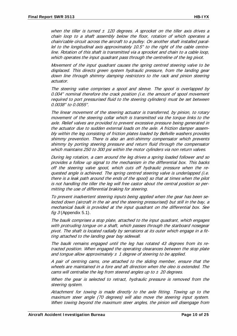
1.10 Aerodrome information
Zurich Airport is located in north-east Switzerland. The Zurich airport runways have the following characteristics:
Runway Dimensions Elevation of the runway thresholds
16/34 3700 x 60 m 1390/1386 ft AMSL
14/32 3300 x 60 m 1402/1402 ft AMSL
10/28 2500 x 60 m 1391/1416 ft AMSL
The airport’s reference elevation is 1416 ft AMSL and its reference temperature is 24.0 °C.
Zurich airport was equipped with Category 9 fire-fighting equipment. The air-port’s professional fire-fighting service was on permanent readiness during flight operations.
1.11 Flight recorders
1.11.1 Cockpit voice recorder
Aircraft HB-IYX was equipped with an Allied Signal solid state cockpit voice re-corder (SSCVR).
1.11.2 Digital flight data recorder
The digital flight data recorder (DFDR) was installed in the tail of the aircraft. It stores the prepared data in a memory unit. The DFDR begins to record as soon as one of the engines is running and the parking brake is released.
The DFDR was removed and analysed after the serious incident. Among other things, the rudder, elevator, brakes and heading parameters were of interest. It was possible to read out the values.
1.12 Information on the location of the serious incident
Zurich-Kloten airport, runway 14, approximately 700 m after the touchdown zone on the grass, approximately 20 m to the right of the runway. The aircraft came to a stop approximately parallel to the centre line of the runway (Appendix 5.2).
1.13 Medical information
Not involved.
1.14 Fire
There was no fire.
1.15 Survival aspects
Since HB-IYX came to a stop on the grass in an area free from obstacles, major structural damage to the aircraft could be avoided. As a result, none of the occu-pants was injured.

Final Report SWR 3513 HB-IYX
Aircraft Accident Investigation Bureau Page 13 of 25
1.16 Tests and research
1.16.1 General
The serious incidents described in section 1.1.1 were investigated independently of each other and on behalf of the Swiss AAIB by the UK Air Accidents Investiga-tion Branch (AAIB), by the aircraft manufacturer and by the nosewheel gear manufacturer.
1.16.2 Conclusions of the UK Air Accidents Investigation Branch
In a technical report dated 27 March 2003, the UK AAIB, after investigating the nosewheel gear of HB-IYX, concluded as follows, among other things:
AAIB Conclusions:
• The very narrow neutral band (0.0038“ – 0.0055“1) makes the system ex-tremely vulnerable to a range of factors which can potentially erode the mar-gins between the position adopted by the valve with the tiller free, and the positions where fluid starts to port to the actuating cylinders.
• Factors which can erode the valve’s effective neutral margin include:
a) Variations in the relative positions of the valve spool and sleeve aris-ing potentially from:
Valve rigging error (neutral point errors introduced during valve setting operations).
Differential thermal response.
Wear and/or bedding-in during service.
b) Spurious variation in the balance of forces acting on the valve spool, producing significant hysteresis and a lack of repeatability in the neu-tral position adopted by the valve under tiller-free conditions. Factors influencing the force-balance include:
Cable tensions.
Friction or sticking in the position-feedback mechanism (fol-low-up spring box).
Friction in the summing linkages (diff box).
Resistance arising from shaft misalignment (e.g. due to varia-tions in grub screw torque on the splined collar).
Friction and/or sticking tendencies in the valve assembly.
Variations in the differential axial forces acting on the valve stem arising from the effects of fluid pressure flow.
1 0.0038” to 0.0055” corresponds to 0.097 mm to 0.140 mm

Final Report SWR 3513 HB-IYX
Aircraft Accident Investigation Bureau Page 14 of 25
• The majority of the left-steer incidents appear to have been caused by a combination of the following factors:
a) A bias in the valve neutral point setting towards the left steer valve crack point
b) Differential thermal expansion, which effectively shifted the neutral point even further towards the left-steer crack-position at reduced temperatures.
• No specific cause of the right steer incidents has been identified. However, the range of factors detailed in conclusion two are potential contributory fac-tors.
• Testing of sample valves has shown significant force hysteresis within the valve itself (i.e. without any contribution from the positioning mechanisms ex-ternal to the valve), sufficient to seriously compromise the control margin.
• The two valves tested by the AAIB to date showed significant variation in the “forces vs displacement” characteristics. These variations remain unex-plained.
• There appears no valid reason for the unusually narrow neutral band em-ployed in the steering valve, and, to date, no technical justification has been offered by the manufacturers for its retention.
• The adoption of a wider neutral band would offer significant advantages by reducing the sensitivity of the valve to the adverse influences detailed previ-ously, whilst presenting no obvious disbenefit.
• The remedial measures proposed by [name of the nosewheel gear manufac-turer] will contribute to a reduction in the probability of future occurrences, particularly those involving steer-left malfunctions, but do not address the fundamental problems arising out of the valve’s inherent lack of centering precision, and its unnecessarily narrow neutral margin.
• The flight deck procedure introduced by [name of the aircraft manufacturer] to check for correct tiller alignment prior touchdown should be viewed as an additional safeguard, and not as a substitute for effective technical action to correct the problem.”
1.16.3 Conclusions of the aircraft manufacturer
In a report dated 12 February 2003, the aircraft manufacturer came to the fol-lowing conclusions:
“Conclusion
Left steering incidents: Caused by a maladjusted steering valve. All uncom-manded left veer incidents have been attributed to steering valve maladjust-ments being amplified by differential contraction brought about by the valve be-ing subject to low ambient temperatures. This problem is being controlled by clarifying the relevant steering valve assembly and test documentation to ensure that steering valve ‘crack position’ (spool movement required to port hydraulic fluid to the steering pistons) is correctly set within 0.0038” to 0.0055” and the actual dimensions recorded at there pressure points (1000, 2000 and 3000 psi) on manufacture/overhaul.

Final Report SWR 3513 HB-IYX
Aircraft Accident Investigation Bureau Page 15 of 25
Right steering incidents: Cause is not the same as the left steering incidents. Three incidents remain unexplained. Noselegs and aircraft involved in these inci-dents have been extensively tested and inspected and so far no problem has been highlighted. Two of the noselegs are quarantined the third was overhauled, in 1991 post incident, returned to service, and remained incident free for 11 years to date. Further discussions, with [manufacturer of the nosewheel gear], are taking place although no causal factors have been identified to date. Perma-nent amendments have been made to the operations manual and enhance op-erational safety by instructing the flight crew to check the tiller before landing and provide advice in the event of an offset tiller in flight.”
1.16.4 Conclusions of the nosewheel gear manufacturer
In a technical report dated 20 December 2002, the manufacturer of the nose-wheel gear came to the following conclusions:
“SUMMARY
This report covers the investigation carried out to ascertain the cause/s of sev-eral aircraft veering predominantly during landing. NLG (nose landing gear) and related NWS (nose wheel steering) have been studied to determine the probable reason/s for the left and right veer.
It is concluded that a mal-adjusted steering valve, at low temperature, is the trigger for the left steer. Recommendations are made to change the related CMM’s (component maintenance manual) and related documents to improve the “valve cracking” setting procedure to introduce the requirement for documented results. Further minor alterations, to the PAT (production acceptance test) and CMM’s of certain components, have been recommended as a result of this inves-tigation.
There has been NO FAULT FOUND on the two “right” incident gears subjected to thorough investigation and testing.
[The nosewheel gear manufacturer] recommended that [aircraft manufacturer] continue to investigate the causes of the right steer incidents especially the pos-sibility of contaminated hydraulic supply.”
1.17 Organisational and management information
1.17.1 The Crossair operator
The Crossair operator was founded in 1975 and in the first few years handled mainly charter traffic using two-engined aircraft for business trips. In 1979 the company purchased aircraft of the type SA 227 TC Metroliner II and commenced regular scheduled flights. In the following two decades the company grew into a large regional airline
Introduction of the aircraft type British Aerospace BAe 146 began in 1990. At the time of the incident, the company was operating among others a fleet of 16 AVRO 146-RJ100 and 4 AVRO 146-RJ85 aircraft.

Final Report SWR 3513 HB-IYX
Aircraft Accident Investigation Bureau Page 16 of 25
1.18 Additional information
1.18.1 General
As part of the investigation of this serious incident, other components were sub-jected to technical analysis. Among other things, the nosewheel tyres and com-ponents of the brake system were examined.
1.18.2 Investigation of the nosewheel tyres
The investigation of the nosewheel tyres by the tyre manufacturer came to the following conclusions (see also Appendix 5.3):
“(…) During the analysis we found scratches running under an angle of approxi-mately 5° and some other ones in an almost radial direction. We did not find any skid marks so the tire did not stop rotating during landing. Due to the rotation, the angle of none of the scratches found in the tread surface will match the an-gle between the wheel and the direction under which the aircraft was travelling. (…) Review of the tread shows an abnormal tread wear, confirming the presence of such angle. On one side of the each rib, the edge shows wear while there is a ridge on the other side of the ribs. Due to the angle between the wheel and the travelling direction, the leading edges of the ribs started to wear faster while the trailing side the edge was pushed down into the groove. (…)”
1.18.3 Investigation of the brakes
The investigation of the components of the brake system can be summarised as follows:
All four components of the braking system on the main landing gear were sub-jected to inspection. It was determined that the brakes on both the main and the auxiliary system were functioning correctly. Nor were any leaks discovered on any hydraulic connections.
1.19 Useful or effective investigation techniques
No new techniques applied.

Final Report SWR 3513 HB-IYX
Aircraft Accident Investigation Bureau Page 17 of 25
2 Analysis
2.1 Technical aspects
2.1.1 General
There is no indication that aircraft HB-IYX was not in an airworthy condition prior to the time of the serious incident.
On the basis of the investigation of the two nosewheel tyres, however, it can be assumed that the nosewheel was not parallel to the longitudinal axis of the air-craft during the landing. On the basis of the crew’s state of knowledge, there was no possibility at the time of the serious incident of detecting the problem at an early stage. A corresponding operational notice was issued by the manufac-turer one year later.
2.1.2 Veering of the aircraft to the left
According to the various reports, the possible reasons for veering to the left were known. Technical proposals for eliminating the problem are available to the manufacturers of the aircraft and of the nosewheel gear.
In an operational notice on 9 May 2001 the aircraft manufacturer issued a proce-dure for detecting the problem of a nosewheel which was not parallel to the air-craft’s longitudinal axis and for taking appropriate measures. It must be stated that an operational procedure cannot solve the known design problems.
2.1.3 Veering of the aircraft to the right
On the part of the aircraft manufacturer, more than 2 years after the incident, no technical explanation could be given of the reasons for the aircraft veering to the right.
In its technical report dated 27 March 2003, the AAIB reaches the same conclu-sions as the aircraft manufacturer, but does not exclude the possibility that indi-vidual factors which cause the veering to the left may also affect veering to the right.
2.1.4 Summary
The UK AAIB report finally comes to the following conclusions with regard to the general problematic with this nosewheel gear:
“It is strongly recommended that in addition to the proposed procedural changes, [the nosewheel gear manufacturer] reconsider the option of introducing the re-vised valve having a broader neutral band, which has already been satisfactorily flight tested, and which should reduce the probability of future occurrences to acceptable limits.”
The Swiss AAIB can comprehend these findings and is of the opinion that the AAIB’s recommendation includes an appropriate design solution for reducing the risk of serious incidents of this kind in the future.

Final Report SWR 3513 HB-IYX
Aircraft Accident Investigation Bureau Page 18 of 25
2.2 Human and operational aspects
2.2.1 Analysis of flight history
According to the crew statements, the aircraft was being operated in accordance with the standard operating procedures.
Taking over the control of the aircraft by the commander after touchdown on runway 14 corresponded to operating procedures. The commander’s reaction to the unexpected veering of the aircraft to the right, with the aid of the rudder and brakes, was appropriate but could not prevent the aircraft from exiting the run-way. The DFDR recordings also substantiate this.
When the aircraft had stopped, the crew assessed the situation as non-dangerous. They decided to evacuate the passengers via the aircraft’s integral stair at the front passenger doors. This decision can be considered as appropriate to the situation.

Final Report SWR 3513 HB-IYX
Aircraft Accident Investigation Bureau Page 19 of 25
3 Conclusions
3.1 Findings
3.1.1 Technical aspects
• There is no indication that aircraft HB-IYX was not in an airworthy condition at the time of the serious incident.
• The nosewheel gear of HB-IYX was not parallel to the longitudinal axis of the aircraft.
• The crew had no possibility of detecting the problem.
• In all, there had been 29 incidents involving the AVRO 146-RJ in which the aircraft veered predominantly to the left after landing.
• There are technical explanations for the veering to the left on landing.
• There are no clear technical explanations for the veering to the right on land-ing.
• The neutral zone of the nosewheel control valve is too small.
• Tests flights have been conducted successfully using a control valve with a broader neutral band.
3.1.2 Crew
• The crew were in possession of appropriate pilots’ licences.
• This flight was a route introduction flight for the commander.
• The assignment of tasks among the crew during landing corresponded to op-erating procedures.
• The commander’s attempts to keep the aircraft on the runway after landing were appropriate.
• The decision to evacuate the occupants via the aircraft’s integral stair at the front passenger doors can be considered as appropriate to the situation.
3.2 Cause
The serious incident is attributable to the fact that the aircraft’s nosewheel gear was not parallel to the longitudinal axis of the aircraft. Subsequently, in the roll-out phase, the aircraft veered to the right and exited the runway. The reason for this could not be established either by the manufacturer, the UK AAIB or the Swiss AAIB.
Final Report SWR 3513 HB-IYX
Aircraft Accident Investigation Bureau Page 20 of 25
4 Safety recommendations
4.1 Re-design of the nosewheel gear steering valve
4.1.1 Safety deficit
On 13 July 2000, aircraft HB-IYX was flying under flight number SWR 3513 from Dusseldorf to Zurich. After landing on runway 14 at Zurich-Kloten airport, the crew lost control of the aircraft. It veered to the right, exited the runway and came to a stop on the grass after travelling approximately 250 m. No-one was in-jured.
Between 1991 and 2001, according to a report by the Air Accidents Investigation Branch (AAIB), UK, there were a total of 29 serious incidents in connection with loss of control of the nosewheel gear on aircraft of the BAe 146/RJ type. There were five occurrences in the years 1991 and 1995. The other 24 incidents oc-curred between 2000 and 2001. In six incidents, aircraft of the operator involved in the present serious incident were involved.
In most of the 29 known incidents, the aircraft veered to the left. Aircraft veered to the right in four cases.
In a technical report dated 27 March 2003, the UK AAIB, after investigating the nosewheel gear of HB-IYX, concluded that a re-design of the steering valve be-came necessary. This re-design should lead to a wider neutral band of the steer-ing valve. Tests carried out by the AAIB came to the conclusion that the re-design proposal was appropriate.
4.1.2 Safety recommendation no. 377
The following safety recommendation was proposed by the AAIB:
„It is strongly recommended that in addition to the proposed procedural changes, Messier Dowty reconsider the option of introducing the revised valve having a broader neutral band, which has already been satisfactorily flight tested, and which should reduce the probability of future occurrences to acceptable limits.”

Final Report SWR 3513 HB-IYX
Aircraft Accident Investigation Bureau Page 21 of 25
4.2 Measures taken since the incident to improve air safety
4.2.1 Notice to Aircrew – NTA OP17
After a series of further similar incidents (cf. section 1.1.1), the Swiss AAIB in its letter of 12 January 2001 made the Federal Office for Civil Aviation (FOCA) aware of the technical problems with the nosewheel gear on aircraft type AVRO 146-RJ. An operational procedure was proposed as an immediate measure until the tech-nical problems are solved.
Subsequently, the aircraft manufacturer issued a procedure on 9 May 2001, in the form of an operational notice, for detecting the problem of a nosewheel gear which is not parallel to the aircraft’s longitudinal axis and for taking appropriate measures:
“NOSE WHEEL STEERING OFFSET
Introduction
Investigations into abnormal nose-wheel gear performance during landing have identified a risk that the nose-wheels may not be aligned centrally before touch down. The reason for any offset is being investigated. Any offset is probably due to a combination of events overcoming the safety design features. One contribu-tion may be low nose-leg oleo pressure; the importance of maintaining correct nose oleo pressure was identified to operators by AOM 01/007V.
A small number of aircraft have reported abnormal steering events during land-ing. The problem has not reoccurred on those aircraft where the nose-leg has been changed. Inspections of the removed nose-legs and of all aircraft have not identified any fault. [The aircraft manufacturer] and [the manufacturer of the nosewheel gear] are urgently undertaking detailed component inspections and ground tests on the nose-wheel steering system to determine the cause of the problem.
The position of the nose-wheel steering hand-wheel normally indicates the nose-leg position. The steering system is designed so that the nose-leg will move to the demanded hand-wheel angle. In normal operation where the nose-wheel moves due to asymmetric braking or when towing then the hand-wheel should match the nose-wheel angle. At extreme nose-wheel angles the hand-wheel is automatically disconnected to prevent damage.
Crew Actions
A check is required at an appropriate point just before landing (approximately 500 ft) that the position of the nose-wheel steering hand-wheel is central. The hand-wheel may move at any time after lowering the landing gear thus the check should be made on final approach just before landing and not immediately after lowering the landing gear. If the hand-wheel is offset it should be returned to the centre position. The hand-wheel may appear to be stiff with respect to normal operation.
If the hand-wheel does not remain in the centre then the crew should be alert to a landing where the nose-wheels may not initially be straight ahead. Where the hand-wheel remains offset its position may not indicate the direction of the nose-wheels. In such an event, the following considerations should be made:
Final Report SWR 3513 HB-IYX
Aircraft Accident Investigation Bureau Page 22 of 25
• A normal landing should be made but anticipating a sudden sideways movement as the nose wheels make ground contact. Rudder control should be used to maintain directional control of the aircraft. Evidence from in-service events indicates that up to full rudder input should maintain direc-tional control.
• Nose-wheel steering should not be used until it is normally required at ap-proximately 80 kts. However, if full rudder inputs become ineffective then the nose wheel steering and braking should be used to assist directional control of the aircraft.
• The nose-wheel steering should work in the normal sense although a small offset about the centre datum and increased stiffness may be felt. Large or rapid hand-wheel inputs should not be made, especially at high speed, to avoid over controlling and loss of steering effectiveness.
• Landings should be conducted on a runway with minimum crosswind com-ponent; tailwind landings should not be made. The widest suitable runway should be selected.
If an immediate landing is not essential, the preferred option with an offset hand-wheel is to perform a go-around to provide time to consider runway and weather conditions. [The aircraft manufacturer] advises that if the NWS hand-wheel is offset, during a subsequent go-around, the undercarriage should be left down (not retracted).
If the hand-wheel is felt to be excessively stiff or directional control is impaired during taxiing the aircraft should not take off.
Recommendation
It is recommended that all operators ensure that flight crews are informed of the possibility of an offset nose-wheel steering hand-wheel before landing.
Any instances of an offset nose-wheel steering hand-wheel in the air of unusual nose-wheel steering during landing or taxiing should be reported to [the aircraft manufacturer] (AOM 01/008V refers).”
Berne, 27 April 2006 Aircraft Accident Investigation Bureau
This report has been prepared solely for the purpose of accident/incident prevention. The legal as-sessment of accident/incident causes and circumstances is no concern of the incident investigation
(art. 24 of the Air Navigation Law).

Final Report SWR 3513 HB-IYX
Aircraft Accident Investigation Bureau Page 23 of 25
5 Appendices
5.1 Drawings of nosewheel steering
fig. 1
fig 3

Final Report SWR 3513 HB-IYX
Aircraft Accident Investigation Bureau Page 24 of 25
5.2 Location of the serious incident
Position of HB-IYX after the serious incident
Tyre traces of HB-IYX on runway 14

Final Report SWR 3513 HB-IYX
Aircraft Accident Investigation Bureau Page 25 of 25
5.3 Pictures on the investigation of the nosewheel tyres
Leading edge Trailing edge