Final Report-FMC-Hardfacing Report
61
1 A Project Report On Improvement of Hardfacing on the Gate Seat Arrangement from a Quality and Cost Perspective BY Sathvik Divi 2010A4PS317H Rahul Rochlani 2011A4PS289H Under the Supervision Of Prof. S.P.Regalla, Mr. Sriram Natarajan, Mr. Nidhin Thomas SUBMITTED IN FULLFILLMENT OF THE REQUIREMENTS OF ME F376: DESIGN ORIENTED PROJECT BIRLA INSTITUTE OF TECHNOLOGY AND SCIENCE PILANI (RAJASTHAN) HYDERABAD CAMPUS
-
Upload
rahul-rochlani -
Category
Documents
-
view
313 -
download
1
Transcript of Final Report-FMC-Hardfacing Report
1
A
Project Report
On
Improvement of Hardfacing on the Gate Seat
Arrangement from a Quality and Cost
Perspective
BY
Sathvik Divi 2010A4PS317H
Rahul Rochlani 2011A4PS289H
Under the Supervision
Of
Prof. S.P.Regalla,
Mr. Sriram Natarajan,
Mr. Nidhin Thomas
SUBMITTED IN FULLFILLMENT OF THE REQUIREMENTS OF
ME F376: DESIGN ORIENTED PROJECT
BIRLA INSTITUTE OF TECHNOLOGY AND SCIENCE PILANI (RAJASTHAN)
HYDERABAD CAMPUS
2
ACKNOWLEDGMENTS
I take this opportunity to express my profound gratitude and deep regard to my
guides Mr. Sriram Natarajan and Mr. Nidhin Thomas for their exemplary guidance,
monitoring, constant encouragement and their unwavering support throughout the
course of this project. I would also like to thank Prof. S.P.Regalla for giving us this
golden opportunity to work with FMC for this project apart from his guidance and
unwavering support throughout this project. I would also like to thank Ms. Aamani
Kanthala for coordinating this project from the Company’s side and ensuring a
cordial and conducive environment.
I would also like to thank the FMC authorities for letting us undertake this project.
Last but not the least; I would like to thank my team mate Sathvik Divi for making
this whole experience a fun-filled one and also for furthering my learning curve in a
big way.
All in all, this project has been an enriching experience and has taught me a lot.
3
Birla Institute of Technology and Science-Pilani,
Hyderabad Campus
Certificate
This is to certify that the project report entitled “Improvement of Hardfacing
in a Gate Seat Arrangement from a Quality and Cost Perspective” submitted
by Mr. Rahul Rochlani, ID No. 2011A4PS289H in fulfillment of the
requirements of the course ME F376, Design Oriented Project Course,
embodies the work done by him under my supervision and guidance.
Date: December ,2013 (Prof. S.P.Regalla)
BITS- Pilani, Hyderabad Campus
4
Contents
Title Page………………………………………………………………………01
Acknowledgements………………………………………………........02
Certificate…………………………………………………………….........03
Abstract……………………………………………………………………….....05
Introduction………………………………………….............................06
Binding Metals……………….………………………………………………...08
Mechanical Properties……………………………………………………...11
Thermal Properties............................................................16
Cemented Carbide…………………………………………………………….17
Chromium Carbide…………………………………………………………….18
Why Tungsten Carbide………………………………………………………19
Structure of Tungsten Carbide…………………………………………..21
Base Metal…………………………………………………………………………23
Hardfacing Techniques……………………………………………………….27
HVOF Thermal Spray Process...............................................35
Method Applying Tungsten Carbide to Inconel using Sintering
Process……………………………………………………………………………….46
Chromium Carbide: An Alternative......................................56
References………………………………………………………………………….61
5
ABSTRACT
Hardfacing is a low cost method of depositing wear resistant surfaces on metal
components to extend service life. It is used in the Slab Gate Valves designed
by FMC Technologies Ltd to be used as the Wellhead Annulus Outlet Valve or
as the Production master and Wing Valve. Although used primarily to restore
worn parts to usable condition, hardfacing is also applied to new components
like the above mentioned valves before being placed into service. In addition
to extending the life of new and worn components, hardfacing provides the
following benefits:
• Fewer replacement parts needed.
• Operating efficiency is increased by reducing downtime.
• Less expensive base metal can be used.
• Overall costs are reduced.
This project aims to understand the process of hardfacing, know why tungsten
carbide is used as the hard facing agent primarily and also the different kinds
of base metals that are used. This project also aims at understanding the
general techniques used in hardfacing. Apart from, it aims to improve the
hardfacing at the gate seat arrangement from a quality as well as a cost
perspective.
6
INTRODUCTION Hardfacing is a metalworking process where a harder and tougher metal is applied to a base
metal. Hardfacing is applied to the base metal to make it more wear resistant and also
durable. In addition to extending the life of new and worn components, hardfacing provides
the following benefits:
• Fewer replacement parts needed.
• Operating efficiency is increased by reducing downtime.
• Less expensive base metal can be used.
• Overall costs are reduced.
There are various ways in which hardfacing can be done. These Processes are:
Welding
Brazing
Sintering
Welding and Brazing processes are commonly used in the process of hardfacing equipments
used in drilling and other such processes. Sintering and other similar powder metallurgical
processes are also used occasionally to Hardface components used in processes like oil
drilling, cylinder body in piston-cylinder arrangements used in automobiles, actuators, etc.
There are various welding processes used in Hardfacing. They are:
Shield Metal Arc Welding
Gas Metal Arc Welding
Oxyfuel Welding
Submerged arc welding
Electroslag welding
Plasma Transferred arc welding
Thermal Spraying
Laser Cladding
Hardpaint
7
The harder and tougher metal that is applied to the base metal is carbide. Some possible
carbides are:
Tungsten Carbide
Chromium Carbide
Titanium Carbide
Tantalum Carbide ( Common name – RAMET)
Molybdenum Carbide
Vanadium Carbide
Hafnium Carbide
Metals like nickel, chromium, cobalt, iron and silver are added to the above mentioned
carbides to make them tougher. Carbides are one of the hardest compounds found. But, as
hard as they might be, they are also very brittle.
8
BINDING METALS
Of all the above mentioned carbides, Tungsten carbide has been extensively exploited in
tool industries because of its high hardness and abrasion resistance. However, processing of
tungsten carbide is difficult as it is a refractory material and cannot be densified by solid
state sintering at high temperatures. Hence, a binder phase is incorporated in the system to
facilitate the densification of the material at lower temperatures.
Binders that are commonly used in Hardfacing are:
Cobalt
Nickel
Chromium
Molybdenum
Iron
Apart from the above mentioned metals, their combinations are also used as binder phases.
The carbide when mixed with the binding phase forms a composite. The consolidation of the
composite is achieved by heating the powders above the melting point of the binder phase.
Pressure-assisted sintering is used to obtain fully-densified cemented carbides with high
volume fractions of tungsten carbide. The liquid formation temperature should be low
enough to avoid the dissolution of tungsten carbide. The use of the binder phase is not
limited to the densification process. The properties of the carbide can be tailored by on the
nature and composition of the binder phase. The binder phase affects the toughness,
ductility, and hardness. The binder phase also affects the abrasion resistance of the
composite. All of these properties shall be seen in the following sections of this report.
The suitability of the binder phase is dictated by the mechanical properties desired for the
final cemented carbide. Conventional cemented carbides often contain cobalt as the binder
phase because it satisfies the desired property requirements. The binder imparts the
necessary toughness and ductility, and facilitates the production of the cemented carbides
at temperatures much lower than the melting point of the carbides. However, cobalt is
strategic material, and is therefore expensive and comparatively rare. Despite early
9
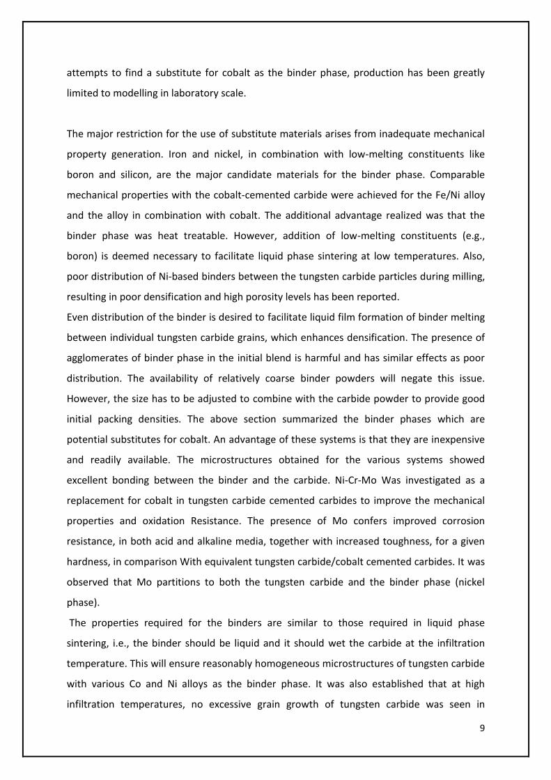
attempts to find a substitute for cobalt as the binder phase, production has been greatly
limited to modelling in laboratory scale.
The major restriction for the use of substitute materials arises from inadequate mechanical
property generation. Iron and nickel, in combination with low-melting constituents like
boron and silicon, are the major candidate materials for the binder phase. Comparable
mechanical properties with the cobalt-cemented carbide were achieved for the Fe/Ni alloy
and the alloy in combination with cobalt. The additional advantage realized was that the
binder phase was heat treatable. However, addition of low-melting constituents (e.g.,
boron) is deemed necessary to facilitate liquid phase sintering at low temperatures. Also,
poor distribution of Ni-based binders between the tungsten carbide particles during milling,
resulting in poor densification and high porosity levels has been reported.
Even distribution of the binder is desired to facilitate liquid film formation of binder melting
between individual tungsten carbide grains, which enhances densification. The presence of
agglomerates of binder phase in the initial blend is harmful and has similar effects as poor
distribution. The availability of relatively coarse binder powders will negate this issue.
However, the size has to be adjusted to combine with the carbide powder to provide good
initial packing densities. The above section summarized the binder phases which are
potential substitutes for cobalt. An advantage of these systems is that they are inexpensive
and readily available. The microstructures obtained for the various systems showed
excellent bonding between the binder and the carbide. Ni-Cr-Mo Was investigated as a
replacement for cobalt in tungsten carbide cemented carbides to improve the mechanical
properties and oxidation Resistance. The presence of Mo confers improved corrosion
resistance, in both acid and alkaline media, together with increased toughness, for a given
hardness, in comparison With equivalent tungsten carbide/cobalt cemented carbides. It was
observed that Mo partitions to both the tungsten carbide and the binder phase (nickel
phase).
The properties required for the binders are similar to those required in liquid phase
sintering, i.e., the binder should be liquid and it should wet the carbide at the infiltration
temperature. This will ensure reasonably homogeneous microstructures of tungsten carbide
with various Co and Ni alloys as the binder phase. It was also established that at high
infiltration temperatures, no excessive grain growth of tungsten carbide was seen in
10
samples with highly alloyed binder phases. This signifies that the alloying additions inhibit
grain growth, perhaps due to limited solubility of the WC ion in the binder.
Generally, Cr-Ni rich binder phases are often known for good corrosion properties. Nickel-
based alloys are used in powder form to enhance Wear and corrosion resistance and are
applied by various hard-facing techniques .These alloys typically contain Ni, Cr, B, Si, and
often small amounts of C and Fe. Both B and Si form low melting eutectics with nickel or
nickel-solid solution. The lower melting point of these alloys over conventional super alloys
is an advantage as it eases the processing. Boron and silicon act as deoxidizers and improve
the properties of the coating material and in bonding to the substrate, as Well as melting
temperature depressants for Ni and Cr via the formation of eutectic liquids. Both are
expected to diffuse into the substrate during the coating procedures.
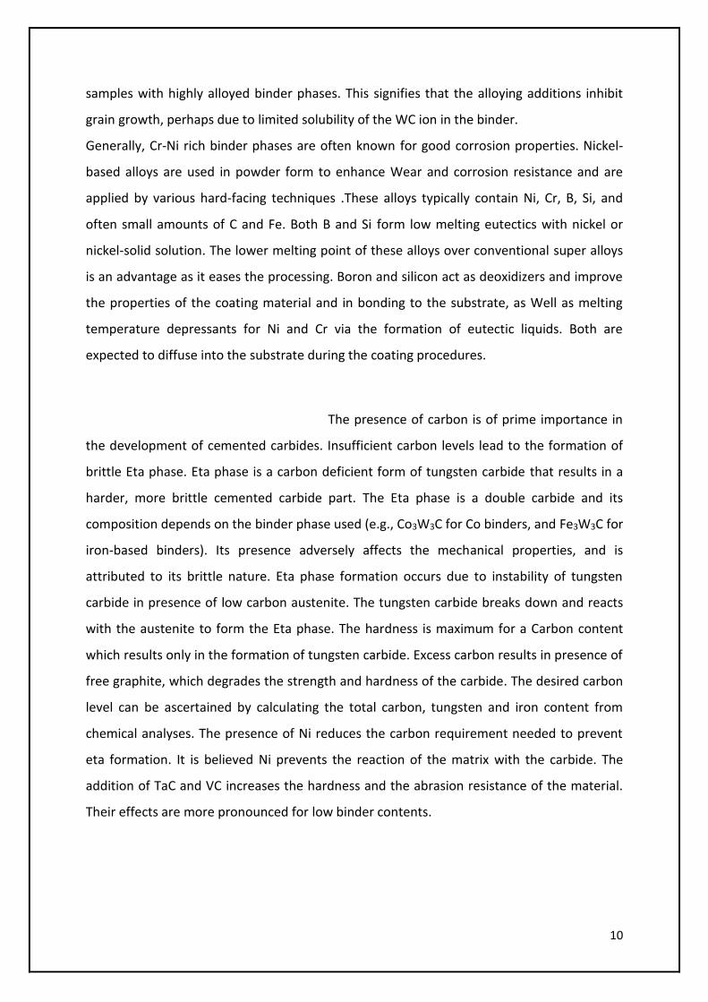
The presence of carbon is of prime importance in
the development of cemented carbides. Insufficient carbon levels lead to the formation of
brittle Eta phase. Eta phase is a carbon deficient form of tungsten carbide that results in a
harder, more brittle cemented carbide part. The Eta phase is a double carbide and its
composition depends on the binder phase used (e.g., Co3W3C for Co binders, and Fe3W3C for
iron-based binders). Its presence adversely affects the mechanical properties, and is
attributed to its brittle nature. Eta phase formation occurs due to instability of tungsten
carbide in presence of low carbon austenite. The tungsten carbide breaks down and reacts
with the austenite to form the Eta phase. The hardness is maximum for a Carbon content
which results only in the formation of tungsten carbide. Excess carbon results in presence of
free graphite, which degrades the strength and hardness of the carbide. The desired carbon
level can be ascertained by calculating the total carbon, tungsten and iron content from
chemical analyses. The presence of Ni reduces the carbon requirement needed to prevent
eta formation. It is believed Ni prevents the reaction of the matrix with the carbide. The
addition of TaC and VC increases the hardness and the abrasion resistance of the material.
Their effects are more pronounced for low binder contents.
11
Mechanical Properties
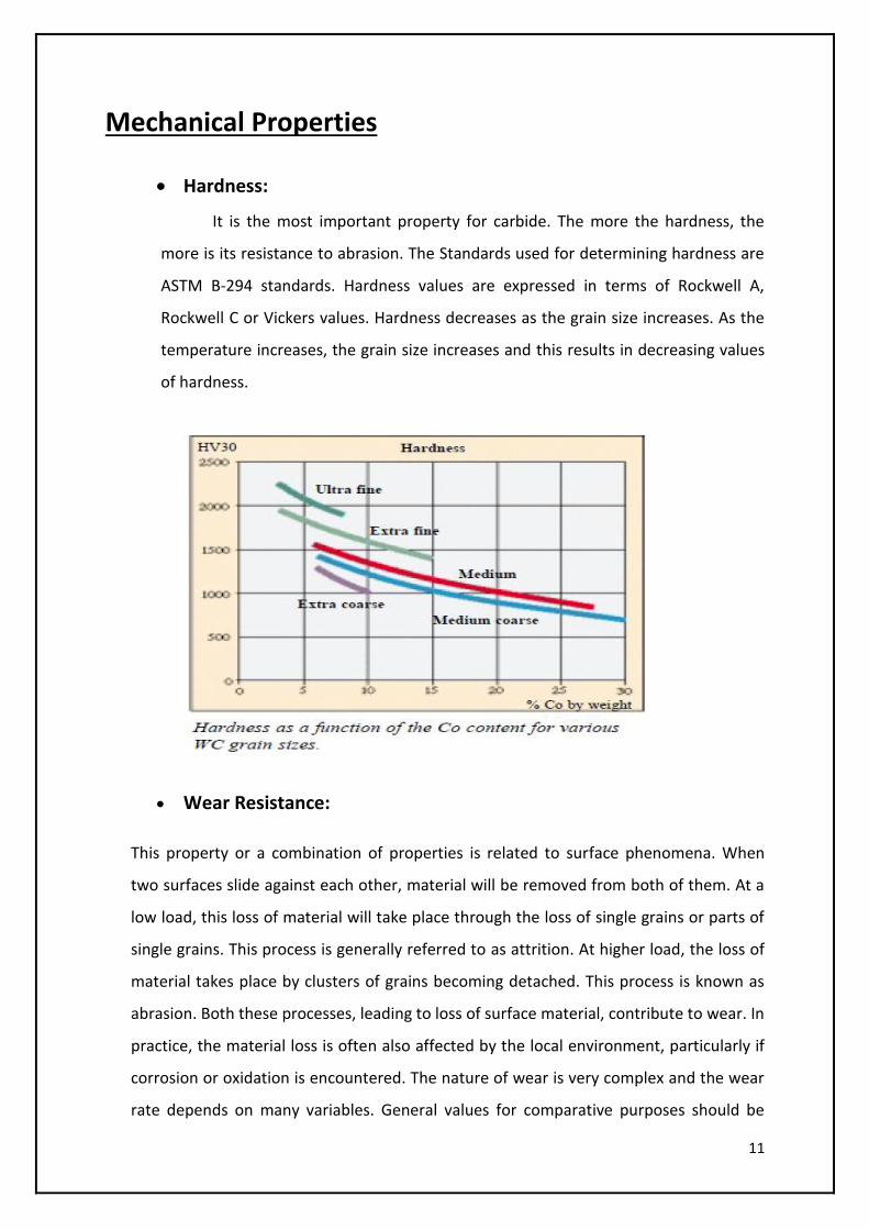
Hardness:
It is the most important property for carbide. The more the hardness, the
more is its resistance to abrasion. The Standards used for determining hardness are
ASTM B-294 standards. Hardness values are expressed in terms of Rockwell A,
Rockwell C or Vickers values. Hardness decreases as the grain size increases. As the
temperature increases, the grain size increases and this results in decreasing values
of hardness.
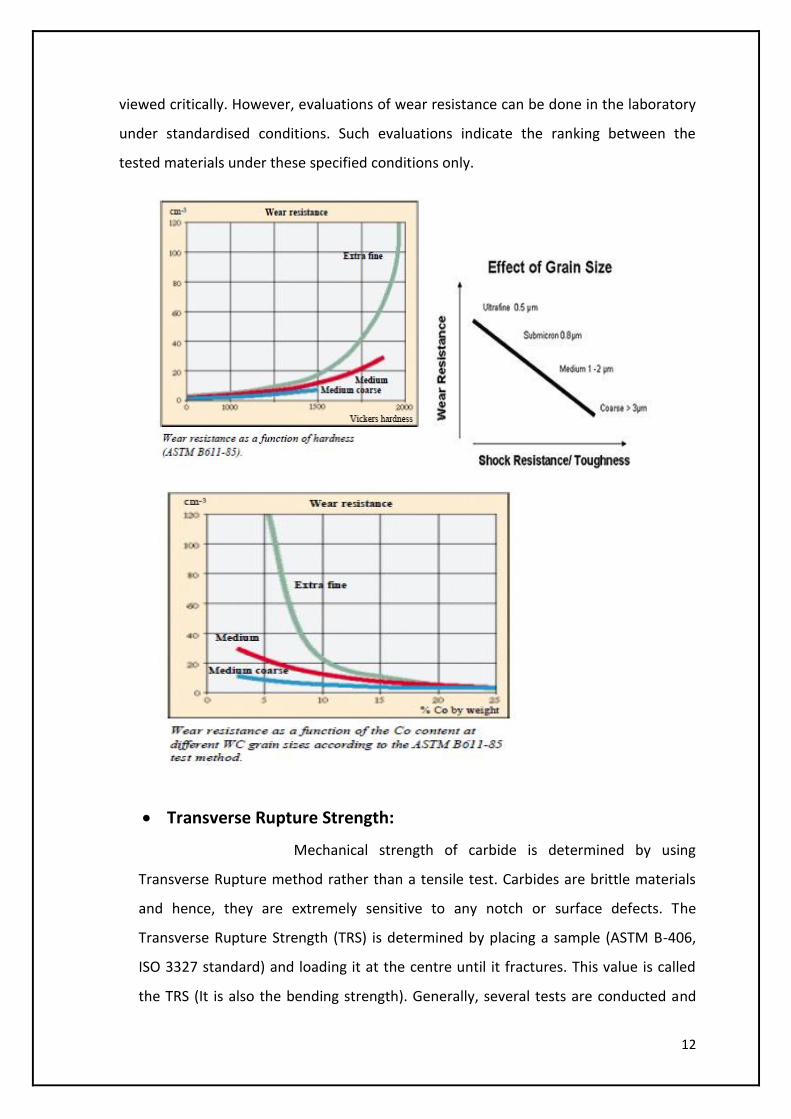
Wear Resistance:
This property or a combination of properties is related to surface phenomena. When
two surfaces slide against each other, material will be removed from both of them. At a
low load, this loss of material will take place through the loss of single grains or parts of
single grains. This process is generally referred to as attrition. At higher load, the loss of
material takes place by clusters of grains becoming detached. This process is known as
abrasion. Both these processes, leading to loss of surface material, contribute to wear. In
practice, the material loss is often also affected by the local environment, particularly if
corrosion or oxidation is encountered. The nature of wear is very complex and the wear
rate depends on many variables. General values for comparative purposes should be
12
viewed critically. However, evaluations of wear resistance can be done in the laboratory
under standardised conditions. Such evaluations indicate the ranking between the
tested materials under these specified conditions only.
Transverse Rupture Strength:
Mechanical strength of carbide is determined by using
Transverse Rupture method rather than a tensile test. Carbides are brittle materials
and hence, they are extremely sensitive to any notch or surface defects. The
Transverse Rupture Strength (TRS) is determined by placing a sample (ASTM B-406,
ISO 3327 standard) and loading it at the centre until it fractures. This value is called
the TRS (It is also the bending strength). Generally, several tests are conducted and
13
their mean value is taken as the final TRS because, carbides being brittle materials,
exhibit a range of fracture values caused by the existence of micro-voids, inherent in
all brittle materials.
TRS increases as the grain size increases. As the binder content increases, the TRS also
increases.
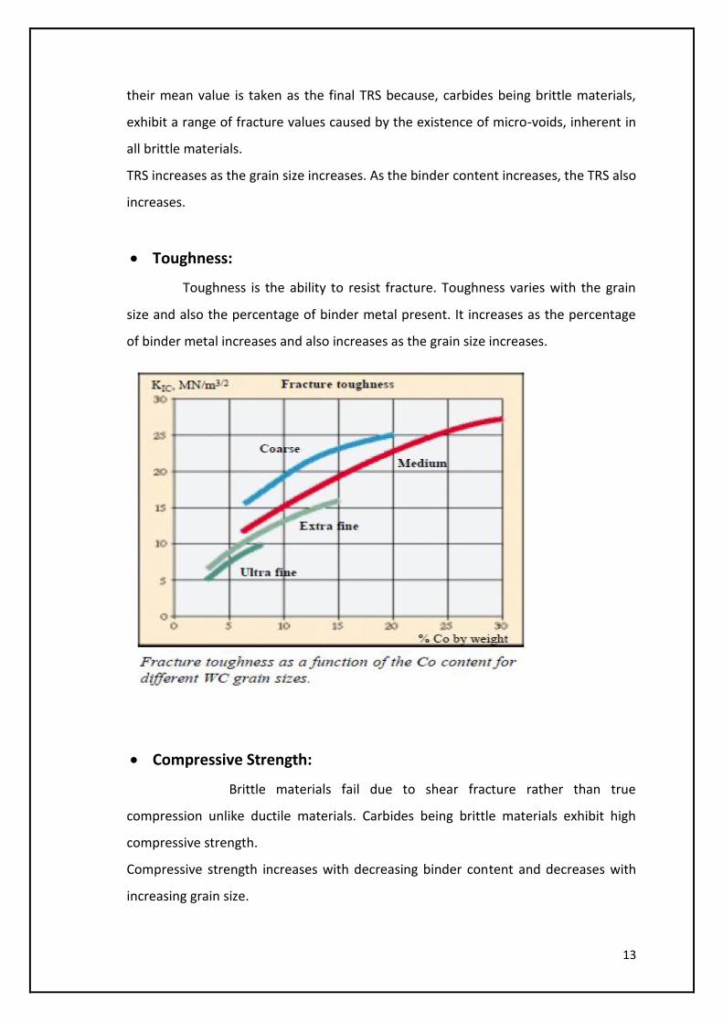
Toughness:
Toughness is the ability to resist fracture. Toughness varies with the grain
size and also the percentage of binder metal present. It increases as the percentage
of binder metal increases and also increases as the grain size increases.
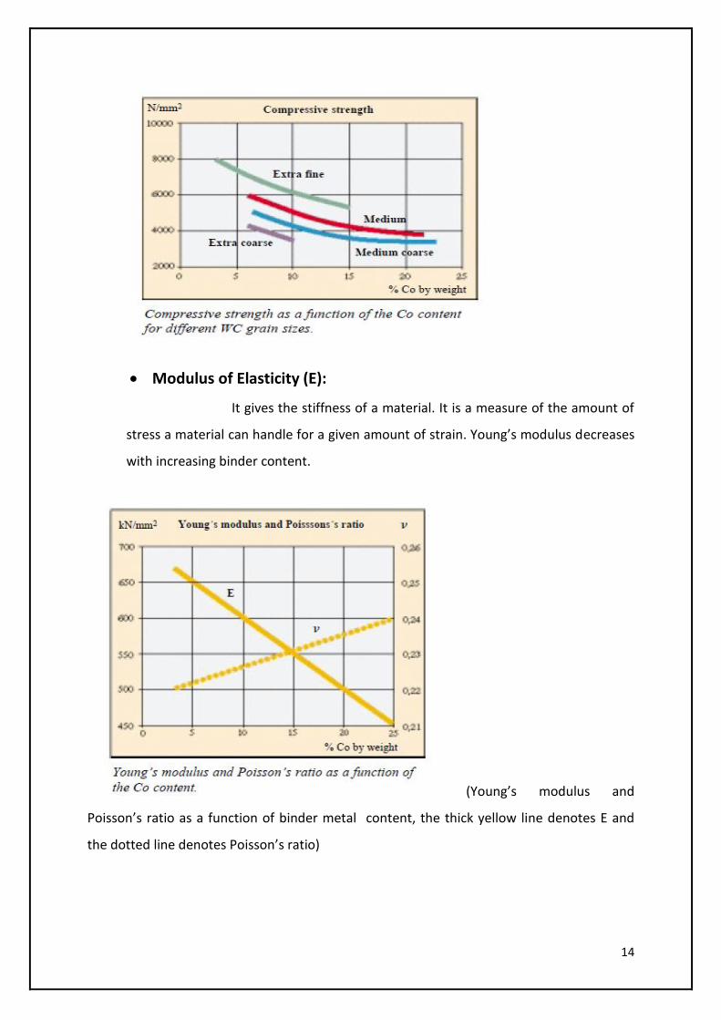
Compressive Strength:
Brittle materials fail due to shear fracture rather than true
compression unlike ductile materials. Carbides being brittle materials exhibit high
compressive strength.
Compressive strength increases with decreasing binder content and decreases with
increasing grain size.
14
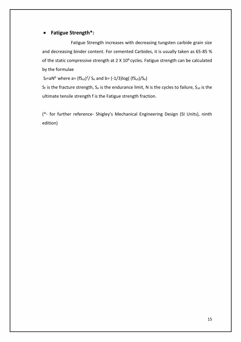
Modulus of Elasticity (E):
It gives the stiffness of a material. It is a measure of the amount of
stress a material can handle for a given amount of strain. Young’s modulus decreases
with increasing binder content.
(Young’s modulus and
Poisson’s ratio as a function of binder metal content, the thick yellow line denotes E and
the dotted line denotes Poisson’s ratio)
15
Fatigue Strength*:
Fatigue Strength increases with decreasing tungsten carbide grain size
and decreasing binder content. For cemented Carbides, it is usually taken as 65-85 %
of the static compressive strength at 2 X 10⁶ cycles. Fatigue strength can be calculated
by the formulae
Sf=aNb where a= (fSut)2/ Se and b= (-1/3)log( (fSut)/Se)
Sf is the fracture strength, Se is the endurance limit, N is the cycles to failure, Sut is the
ultimate tensile strength f is the Fatigue strength fraction.
(*- for further reference- Shigley’s Mechanical Engineering Design (SI Units), ninth
edition)
16
THERMAL PROPERTIES
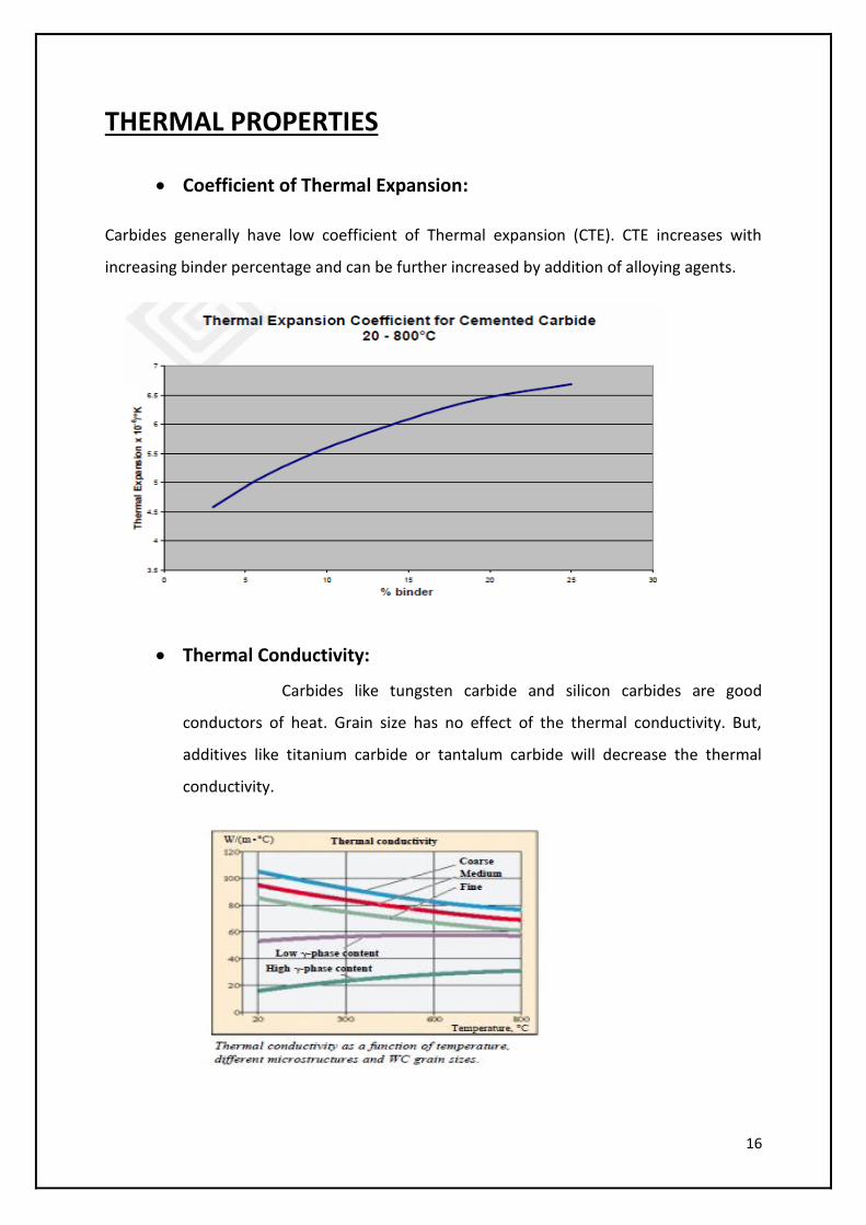
Coefficient of Thermal Expansion:
Carbides generally have low coefficient of Thermal expansion (CTE). CTE increases with
increasing binder percentage and can be further increased by addition of alloying agents.
Thermal Conductivity:
Carbides like tungsten carbide and silicon carbides are good
conductors of heat. Grain size has no effect of the thermal conductivity. But,
additives like titanium carbide or tantalum carbide will decrease the thermal
conductivity.
17
Cemented Carbide (Tungsten Carbide + Co/Ni)
Tungsten carbide is widely used today for the purpose of hardfacing. Binding metals like
Nickel or cobalt are added to it to make it tougher. WC+Ni/Co are also known as cemented
carbides. There are various grades of cemented carbides available based on the percentage
of binder materials and also the percentage of carbon present. Cemented Carbide is
preferred for parts that must withstand all forms of wear (abrasion, erosion, corrosion,
metal to metal galling) and exhibit a high degree of toughness.
Tungsten carbide with nickel/cobalt exhibits high degree of toughness and high compressive
strength, resists deflection ad retains its hardness values at high temperatures. Tungsten
Carbide is extensively used for hardfacing these days because of its unique combination of
toughness and hardness. But, Tungsten carbide has a density of around 14 g/cc. The
particles’ specific gravity is high (twice the value of the metal matrix). This makes them to
sink into the matrix thus exposing the outer layer of the base metal. This leads to a relatively
rapid wear. Also, the cost of hardfacing a base metal with tungsten carbide is costly. Apart
from that, it has been found that a brittle inter-metallic phase frequently forms at the inter-
phase between the particles and the base metal matrix. This too leads to premature wear.
WC is resistant to most corrosive media. Presence of binder material makes it susceptible to
leaching in the presence of a strong acid or alkali. The binder material is attacked by the
strong corrosive media leaving an unsupported carbide skeleton. The carbide particles then
abrade away quite readily exposing a new surface to be attacked.
WC-Co grades are corrosion resistant at neutral pH (7). Same holds true for grades that
contain additives like TiC, Tac, Nbc, etc. Certain Tic-Ni grades possess highest corrosion
resistance down to pH 1. But, these are inferior to WC-Co grades in thermal conductivity
and are more brittle.
When Corrosion resistance is the prime design criteria, specially alloyed WC-Ni grades are
used. These grades are resistant till pH 2 to 3. Also, at high temperatures WC decomposes
to tungsten and carbon. Oxidation starts at a temperature of 500-6000 C. WC reacts with
Fluorine at room temperature and chlorine at higher temperatures. WC dissolves readily in
H2O2 and is unreactive to H2 till its melting point.
18
Chromium Carbide + Nickel
According Patent No. 4173457 filed in 1978 by Thomas J Smith, Chromium Carbide with
Nickel as the binding metal can be used to hardface base metals like steels. The Specific
gravity of Chromium carbide is less than that of tungsten carbide. This results in a better
steel matrix. As the Chromium carbide particles have density approximating that of steel
(density of chromium carbide particles is around 6.8-7.0 g/cc), there is a more optimum
distribution of particles throughout the steel matrix when compared to the matrix in case of
cemented carbide, where the carbide particles tend to sink into the matrix due to their high
specific gravity. Also, no brittle inter-metallic phase exits at the interface of the particles and
the matrix.
Also, no additional techniques are required to enhance particle bonding. This kind of
hardfacing is also more economical than WC-Ni/Co.
The hardness of Chromium Carbides bound with Nickel is usually in the range of 87.8-88.8
Rockwell A. A typical Composition is 10% Ni and this gives a hardness of 88.1 on Rockwell A
scale at a density of 6.9 g/cc.
19
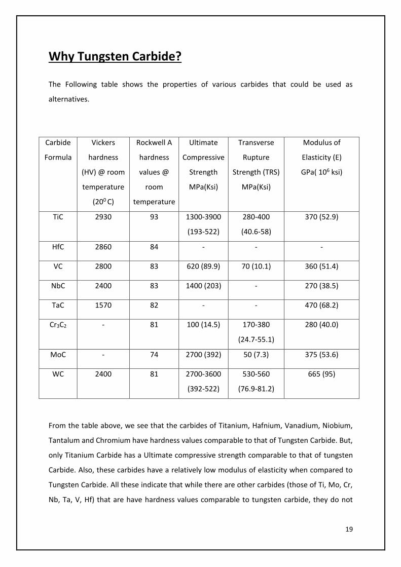
Why Tungsten Carbide?
The Following table shows the properties of various carbides that could be used as
alternatives.
Carbide
Formula
Vickers
hardness
(HV) @ room
temperature
(200 C)
Rockwell A
hardness
values @
room
temperature
Ultimate
Compressive
Strength
MPa(Ksi)
Transverse
Rupture
Strength (TRS)
MPa(Ksi)
Modulus of
Elasticity (E)
GPa( 106 ksi)
TiC 2930 93 1300-3900
(193-522)
280-400
(40.6-58)
370 (52.9)
HfC 2860 84 - - -
VC 2800 83 620 (89.9) 70 (10.1) 360 (51.4)
NbC 2400 83 1400 (203) - 270 (38.5)
TaC 1570 82 - - 470 (68.2)
Cr3C2 - 81 100 (14.5) 170-380
(24.7-55.1)
280 (40.0)
MoC - 74 2700 (392) 50 (7.3) 375 (53.6)
WC 2400 81 2700-3600
(392-522)
530-560
(76.9-81.2)
665 (95)
From the table above, we see that the carbides of Titanium, Hafnium, Vanadium, Niobium,
Tantalum and Chromium have hardness values comparable to that of Tungsten Carbide. But,
only Titanium Carbide has a Ultimate compressive strength comparable to that of tungsten
Carbide. Also, these carbides have a relatively low modulus of elasticity when compared to
Tungsten Carbide. All these indicate that while there are other carbides (those of Ti, Mo, Cr,
Nb, Ta, V, Hf) that are have hardness values comparable to tungsten carbide, they do not
20
offer the kind of toughness that tungsten carbide offers for the same hardness. An optimum
mix of hardness and Toughness is desired for Carbide that is to be used in Hardfacing. Also,
we can see from the young’s modulus values that Tungsten Carbide offers the maximum
resistance to deflection than other carbides.
Hence, Tungsten Carbide with suitable Binding metals such as Chromium, Nickel, Cobalt and
etc is used for hardfacing.
The preferable particle size is 14-30 mesh (US size standard). The average grain sizes
observed are usually in the range of 0.5 to 25 microns. The preferred range of grain size is
0.5 to 15 microns. The Binder percentages are also within the range 3 to 25 %.
For carbides that are produced by sintering, the particles undergo grain growth. For
example, in the case of chromium carbide, particles having an average size of 0.5 to 5.0
microns are used, the grains will normally grow in size to average within the range 5 to 25
microns. As we have seen earlier, that Grain growth increases the toughness and decreases
the hardness of a material, certain compounds are added to prevent or restrict the growth
of the grains. The compounds that are added to restrict the size of the grains are called as
growth inhibitors. Growth inhibitors like titanium carbide, molybdenum carbide, vanadium
carbide, tantalum carbide are added either in combination or alone. Some carbides like
Tantalum Carbide are also used as an anti-galling agent.
The base metal matrix can further be improved by adding certain bonding agents. These
bonding agents are fine powders that are used in minor amounts depending upon the
degree of additional alloying of the matrix which is desired. They enhance the boding of the
particles with the matrix, improve the welding characteristics of hardfacing materials and
assure a uniform distribution of particles in the matrix.
Some of the bonding agents that are used and their preferred ranges are given in the table
below.
21
Bonding Agent Preferred Range (%)
Ferrosilicon (50/50) 0.5-15
Ferromanganese (35/65) 0.2-5
Siliconmanganese (40/60) 0.2-5
Ferromolybdennum (40/60) 0.2-5
Ferroboron (80/20) 1.0-10
Carbon 0.01-2
Chromium Carbide 0.5-10
Nichrome (80/20) 0.5-15
Ferrochrome 0.2-5
Structure of Tungsten Carbide
Tungsten Carbide exhibits three structures. They are:
α-WC
β-WC
Gamma WC
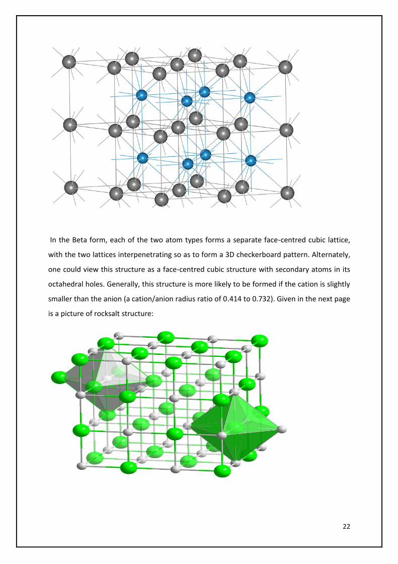
The alpha form has a hexagonal structure. It consists of only Tungsten and Carbon. When
Binding metals like Nickel and Cobalt are added, we get a Rock-salt like structure and this is
called the Beta form. When additional compounds are added (like TaC, TiC, nichrome as
growth inhibitors or bonding agents), we get a Gamma form.
A picture of the alpha form of tungsten carbide is given below. The Gray atoms are Carbon
and the blue atoms are tungsten.
22
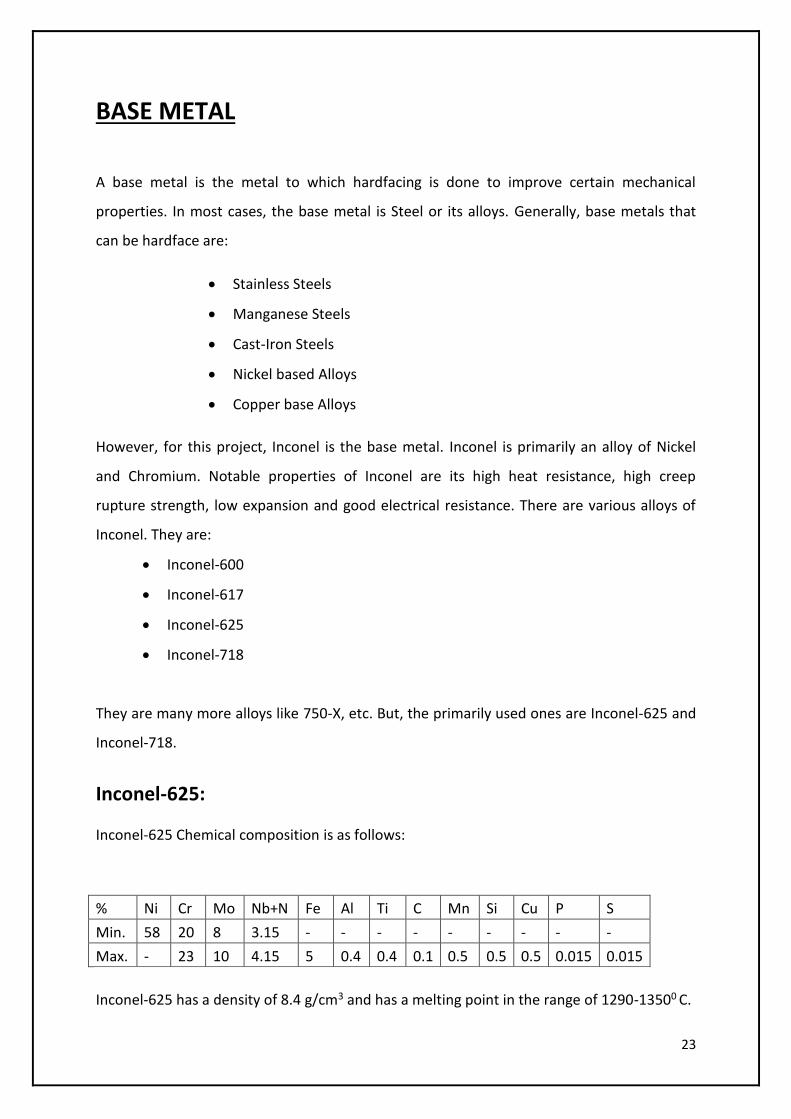
In the Beta form, each of the two atom types forms a separate face-centred cubic lattice,
with the two lattices interpenetrating so as to form a 3D checkerboard pattern. Alternately,
one could view this structure as a face-centred cubic structure with secondary atoms in its
octahedral holes. Generally, this structure is more likely to be formed if the cation is slightly
smaller than the anion (a cation/anion radius ratio of 0.414 to 0.732). Given in the next page
is a picture of rocksalt structure:
23
BASE METAL
A base metal is the metal to which hardfacing is done to improve certain mechanical
properties. In most cases, the base metal is Steel or its alloys. Generally, base metals that
can be hardface are:
Stainless Steels
Manganese Steels
Cast-Iron Steels
Nickel based Alloys
Copper base Alloys
However, for this project, Inconel is the base metal. Inconel is primarily an alloy of Nickel
and Chromium. Notable properties of Inconel are its high heat resistance, high creep
rupture strength, low expansion and good electrical resistance. There are various alloys of
Inconel. They are:
Inconel-600
Inconel-617
Inconel-625
Inconel-718
They are many more alloys like 750-X, etc. But, the primarily used ones are Inconel-625 and
Inconel-718.
Inconel-625:
Inconel-625 Chemical composition is as follows:
% Ni Cr Mo Nb+N Fe Al Ti C Mn Si Cu P S
Min. 58 20 8 3.15 - - - - - - - - -
Max. - 23 10 4.15 5 0.4 0.4 0.1 0.5 0.5 0.5 0.015 0.015
Inconel-625 has a density of 8.4 g/cm3 and has a melting point in the range of 1290-13500 C.
24
Properties of Inconel-625 are:
Excellent corrosion resistance of different kinds of media in both oxidation and
reduction environments
Excellent resistance of pitting and crevice corrosion, and won't happen stress
corrosion cracking because of chloride
Excellent resistance of the inorganic acid corrosion performance, such as nitric
acid, phosphoric acid, sulfuric acid, hydrochloric acid and the mixture of sulfuric
acid and hydrochloric acid
Excellent corrosion resistance of different kinds of inorganic acid mixture
performance
Good corrosion resistance of a variety of concentrations of hydrochloric acid
when the temperature up to 40℃
Good machining and welding, no weld cracking sensitivity
Have pressure vessel authentication for the wall temperature between -196 to
450℃
Apply for the highest standard lever VII of acidic environment
Inconel-625 has a face-centred cubic lattice structure. Dissolve out the carbon granule and
instability quaternary phase, then change it to stability Ni3 (Nb, Ti) trimetric lattice around
650℃ after a long time heat preservation. Nickel-chromium content will strength the
mechanical performance in the state solution while suppress the plasticity. Inconel-625 is
also known to have very good corrosion resistance in many media, especially with excellent
resistance to pitting, crevice corrosion, inter-crystalline corrosion, and erode in oxide, also
good resistance to inorganic acid corrosion, such as nitric acid, phosphoric acid, sulphuric
acid and hydrochloric acid. Inconel-625 can resist the alkali and organic acid corrosion in the
oxidation and reduction environment. Effect resists the chloride reduction stress corrosion
cracking. It exhibits high corrosion resistance to the sea-water and salting liquid, as well as
at high temperatures. Inconel-625 is also known for its resistance towards chlorine
corrosion.
Inconel-625 is typically used in the following fields:
25
The Organic chemical process parts containing chloride, especially in the use of
acid chloride catalyst
The digester and bleacher in the use of paper pulp and paper making industry
Absorption tower, re-heater, gas import board, fan, blender, fair water fin, flue
and so on for using in flue gas desulfurization system
The equipment and parts in the use of acidic gas environments
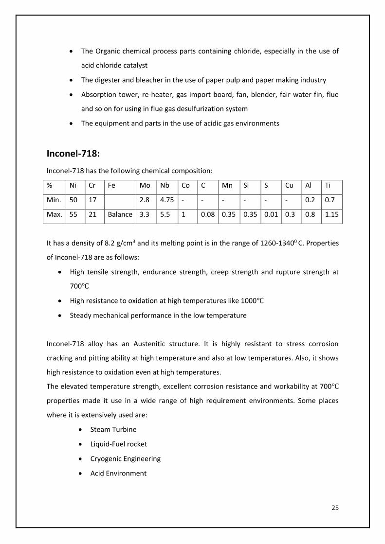
Inconel-718:
Inconel-718 has the following chemical composition:
% Ni Cr Fe Mo Nb Co C Mn Si S Cu Al Ti
Min. 50 17 2.8 4.75 - - - - - - 0.2 0.7
Max. 55 21 Balance 3.3 5.5 1 0.08 0.35 0.35 0.01 0.3 0.8 1.15
It has a density of 8.2 g/cm3 and its melting point is in the range of 1260-13400 C. Properties
of Inconel-718 are as follows:
High tensile strength, endurance strength, creep strength and rupture strength at
700℃
High resistance to oxidation at high temperatures like 1000℃
Steady mechanical performance in the low temperature
Inconel-718 alloy has an Austenitic structure. It is highly resistant to stress corrosion
cracking and pitting ability at high temperature and also at low temperatures. Also, it shows
high resistance to oxidation even at high temperatures.
The elevated temperature strength, excellent corrosion resistance and workability at 700℃
properties made it use in a wide range of high requirement environments. Some places
where it is extensively used are:
Steam Turbine
Liquid-Fuel rocket
Cryogenic Engineering
Acid Environment
26
Nuclear Engineering
To sum it up, Inconel and its alloys are oxidation and corrosion resistant materials well
suited for extreme environments subjected to high pressure and kinetic energy. When
heated, Inconel forms a thick, passive and a stable oxide layer. This protects the surface
from further attack. Inconel retains its strength at high temperatures. This makes it
attractive for high temperature applications where aluminium and steel would succumb to
creep as a result of thermally induced crystal vacancies. Inconel’s high temperature strength
is developed by solid solution strengthening or precipitation hardening (depends on the
alloy). In age hardening, small amounts of Niobium combine to form the inter-metallic
compound Ni3Nb (Gamma Prime). Gamma prime forms small cubic crystals that inhibit
creep and slip effectively at elevated temperatures.
It is difficult to machine Inconel using traditional techniques because of rapid work
hardening. Work Hardening causes the workpiece or the tool to deform plastically. The
majority of machining can be performed with the workpiece in a solution form.
Welding Inconel alloys is difficult due to cracking and microstructural segregation of alloying
elements in the heat affected zone.Inconel is often encountered in extreme environments.
It is commonly used in gas turbine blades, seals, combustors, turbocharger rotors and seals,
high temperature fasteners, chemical processing and pressure vessels, heat exchanger
tubing, natural gas processing with contaminants such as H2S and CO2.
Hence, Inconel alloys are generally subjected to heat treatment techniques. Inconel-718 has
good welding characteristics after it is subjected to age-hardening or annealing.
27
Hardfacing Techniques
Metal Parts often fail their intended use because of wear, which causes them to lose their
dimension and functionality. Hardfacing is the application of wear resistant weld metals to a
part’s surface. It can be one by:
Welding
Brazing
Sintering
Welding techniques to apply hardfacing to a base metal are:
Tungsten Inert gas Welding
Metal Arc Welding
Gas Metal Arc Welding
Submerged Arc Welding
Plasma Transferred Arc Welding
Laser Weld Deposition
Power Weld Deposition
High Velocity Oxy Fuel (HVOF) Spray Deposition
Plasma Spray Deposition
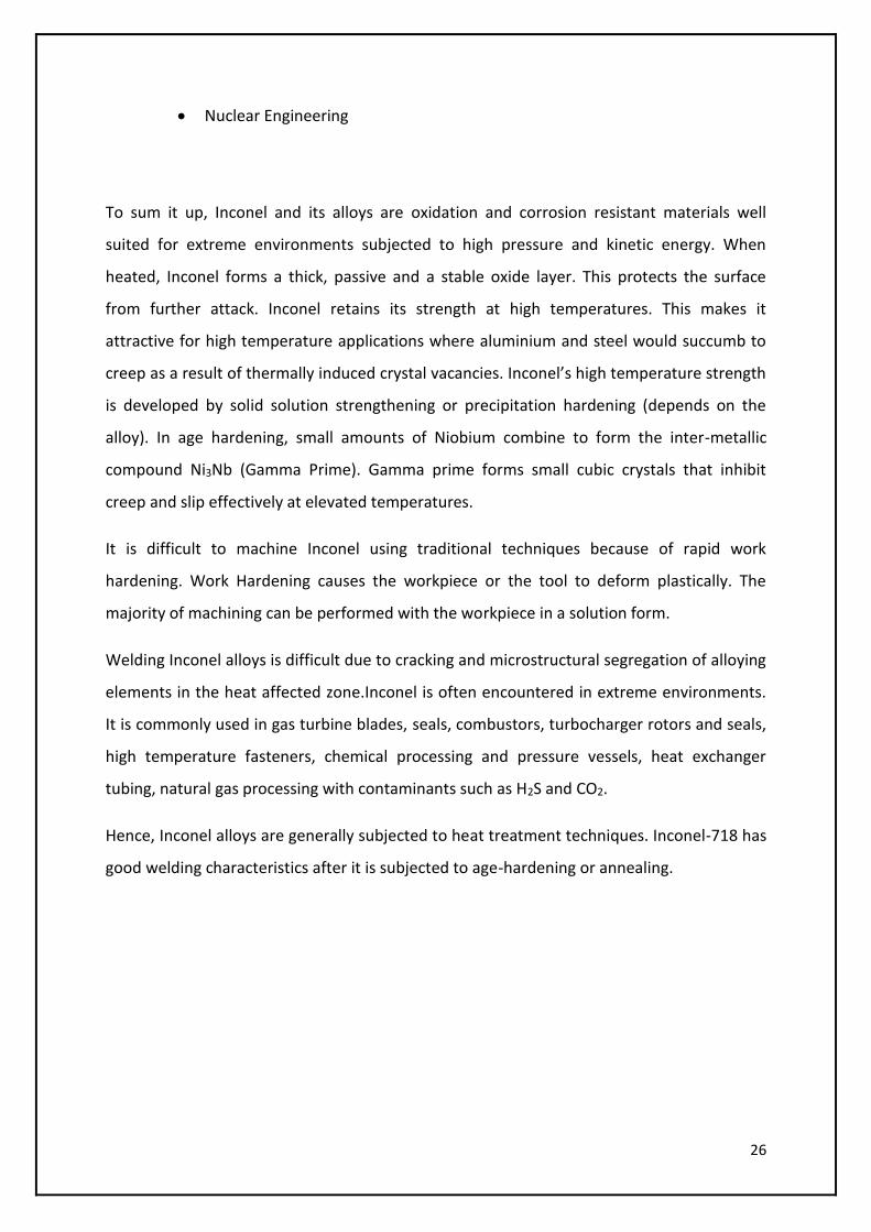
Tungsten Inert Gas Welding
In TIG (Tungsten Inert Gas) welding, an arc is drawn
between a non-consumable tungsten electrode and
the work piece. The electrode, the arc and the weld
pool are protected from the atmosphere with an
inert shielding gas. For manual welding, the
hardfacing material is in the form of a rod.
Advantages of the TIG process include simple
manual operation and good control of the welding
arc. The process can also be mechanized, in which
case a manipulator is used to move the work piece
28
in relation to the welding torch and the hardfacing rod or wire. Rods are also used for
hardfacing with the Oxy-Acetylene welding process. With the correct operation, a very low
level of iron dilution can be achieved in the overlay.
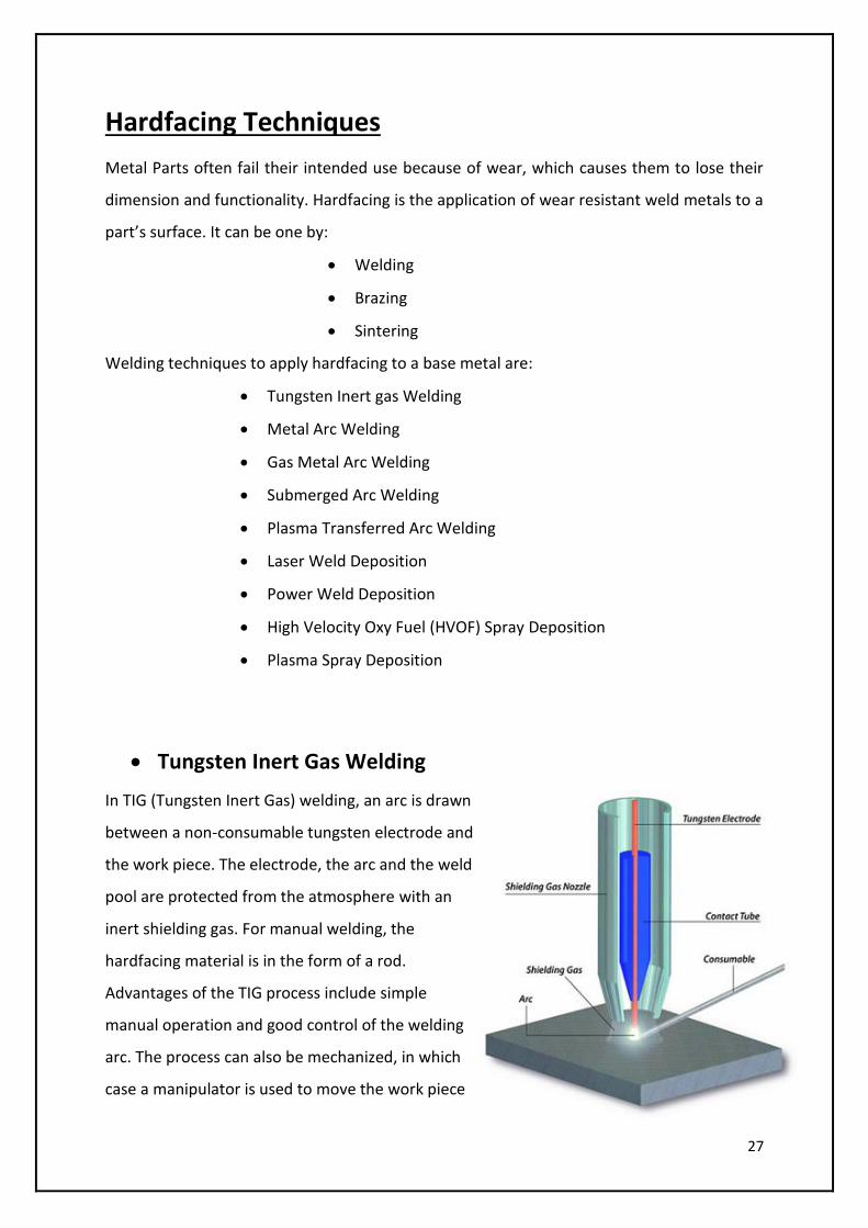
Metal Arc Welding:
In this process an arc is drawn between a coated
consumable electrode and the work piece. The
metallic core-wire is melted by the arc and is
transferred to the weld pool as molten drops. The
electrode coating also melts to form a gas shield
around the arc and the weld pool as well as slag on
the surface of the weld pool, thus protecting the
cooling weld pool from the atmosphere. The slag
must be removed after each layer.
Manual Metal Arc (MMA) welding is still a widely
used hardfacing process. Due to the low cost of
the equipment, the low operating costs of the
process and the ease of transporting the
equipment, this flexible process is ideally suited to
repair work. Benefits of MMA Welding are:
Flexible
Low Cost
Mobile
Ideal for Repairs
29
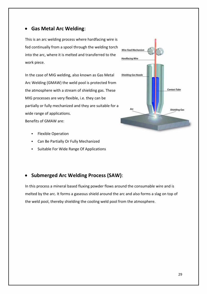
Gas Metal Arc Welding:
This is an arc welding process where hardfacing wire is
fed continually from a spool through the welding torch
into the arc, where it is melted and transferred to the
work piece.
In the case of MIG welding, also known as Gas Metal
Arc Welding (GMAW) the weld pool is protected from
the atmosphere with a stream of shielding gas. These
MIG processes are very flexible, i.e. they can be
partially or fully mechanized and they are suitable for a
wide range of applications.
Benefits of GMAW are:
Flexible Operation
Can Be Partially Or Fully Mechanized
Suitable For Wide Range Of Applications
Submerged Arc Welding Process (SAW):
In this process a mineral based fluxing powder flows around the consumable wire and is
melted by the arc. It forms a gaseous shield around the arc and also forms a slag on top of
the weld pool, thereby shielding the cooling weld pool from the atmosphere.
30
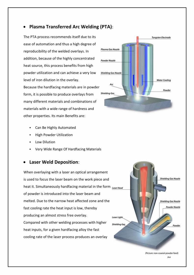
Plasma Transferred Arc Welding (PTA):
The PTA process recommends itself due to its
ease of automation and thus a high degree of
reproducibility of the welded overlays. In
addition, because of the highly concentrated
heat source, this process benefits from high
powder utilization and can achieve a very low
level of iron dilution in the overlay.
Because the hardfacing materials are in powder
form, it is possible to produce overlays from
many different materials and combinations of
materials with a wide range of hardness and
other properties. Its main Benefits are:
Can Be Highly Automated
High Powder Utilization
Low Dilution
Very Wide Range Of Hardfacing Materials
Laser Weld Deposition:
When overlaying with a laser an optical arrangement
is used to focus the laser beam on the work piece and
heat it. Simultaneously hardfacing material in the form
of powder is introduced into the laser beam and
melted. Due to the narrow heat affected zone and the
fast cooling rate the heat input is low, thereby
producing an almost stress free overlay.
Compared with other welding processes with higher
heat inputs, for a given hardfacing alloy the fast
cooling rate of the laser process produces an overlay

31
with a significantly higher hardness and finer microstructure.Benefits of Laser weld
deposition are:
Low Heat Input
Fast Cooling
Almost Stress Free Overlays
High Hardness
Fine Microstructure
Powder Weld Deposition:
A specially designed Oxy-Acetylene torch is used
for powder welding. The work piece is heated
with the torch. The powder is introduced into the
gas stream from the integral powder hopper and
then transferred to the work piece through a
flame.
This process is similar to the Oxy-Acetylene
process with the exception that the hardfacing
takes place at lower temperatures. This
minimizes oxidation and distortion of the work
piece ad enables easy surfacing of edges.
Benefits of Powder welding are:
Low Dilution
Easy Application
Low Distortion
Ideal for Edge Building
32
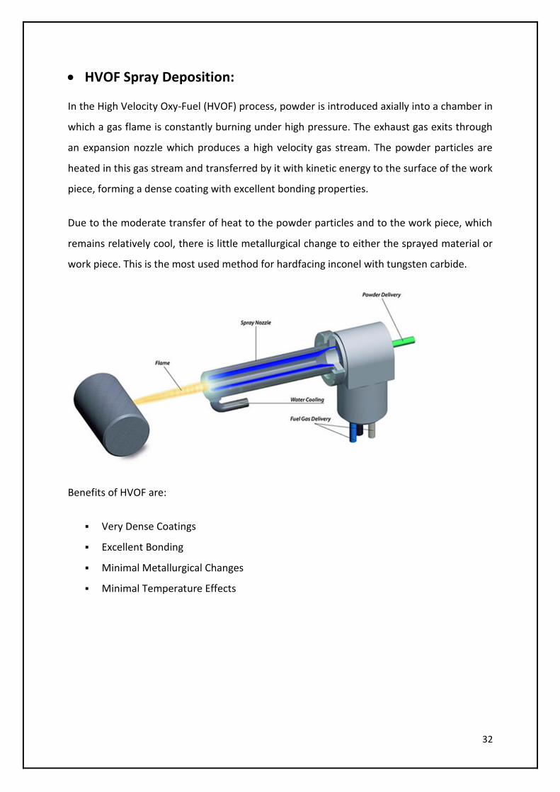
HVOF Spray Deposition:
In the High Velocity Oxy-Fuel (HVOF) process, powder is introduced axially into a chamber in
which a gas flame is constantly burning under high pressure. The exhaust gas exits through
an expansion nozzle which produces a high velocity gas stream. The powder particles are
heated in this gas stream and transferred by it with kinetic energy to the surface of the work
piece, forming a dense coating with excellent bonding properties.
Due to the moderate transfer of heat to the powder particles and to the work piece, which
remains relatively cool, there is little metallurgical change to either the sprayed material or
work piece. This is the most used method for hardfacing inconel with tungsten carbide.
Benefits of HVOF are:
Very Dense Coatings
Excellent Bonding
Minimal Metallurgical Changes
Minimal Temperature Effects
33
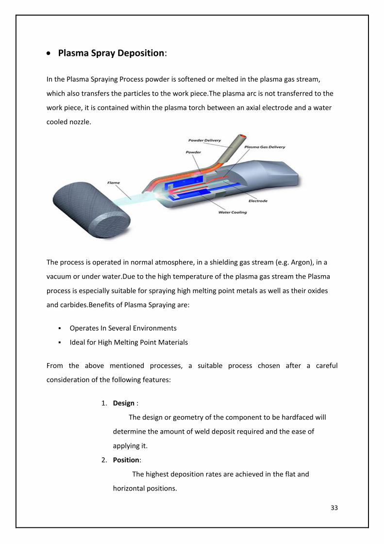
Plasma Spray Deposition:
In the Plasma Spraying Process powder is softened or melted in the plasma gas stream,
which also transfers the particles to the work piece.The plasma arc is not transferred to the
work piece, it is contained within the plasma torch between an axial electrode and a water
cooled nozzle.
The process is operated in normal atmosphere, in a shielding gas stream (e.g. Argon), in a
vacuum or under water.Due to the high temperature of the plasma gas stream the Plasma
process is especially suitable for spraying high melting point metals as well as their oxides
and carbides.Benefits of Plasma Spraying are:
Operates In Several Environments
Ideal for High Melting Point Materials
From the above mentioned processes, a suitable process chosen after a careful
consideration of the following features:
1. Design :
The design or geometry of the component to be hardfaced will
determine the amount of weld deposit required and the ease of
applying it.
2. Position:
The highest deposition rates are achieved in the flat and
horizontal positions.
34
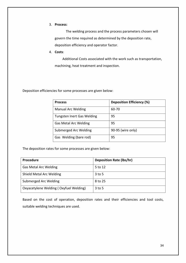
3. Process:
The welding process and the process parameters chosen will
govern the time required as determined by the deposition rate,
deposition efficiency and operator factor.
4. Costs:
Additional Costs associated with the work such as transportation,
machining, heat treatment and inspection.
Deposition efficiencies for some processes are given below:
Process Deposition Efficiency (%)
Manual Arc Welding 60-70
Tungsten Inert Gas Welding 95
Gas Metal Arc Welding 95
Submerged Arc Welding 90-95 (wire only)
Gas Welding (bare rod) 95
The deposition rates for some processes are given below:
Procedure Deposition Rate (lbs/hr)
Gas Metal Arc Welding 5 to 12
Shield Metal Arc Welding 3 to 5
Submerged Arc Welding 8 to 25
Oxyacetylene Welding ( Oxyfuel Welding) 3 to 5
Based on the cost of operation, deposition rates and their efficiencies and tool costs,
suitable welding techniques are used.
35
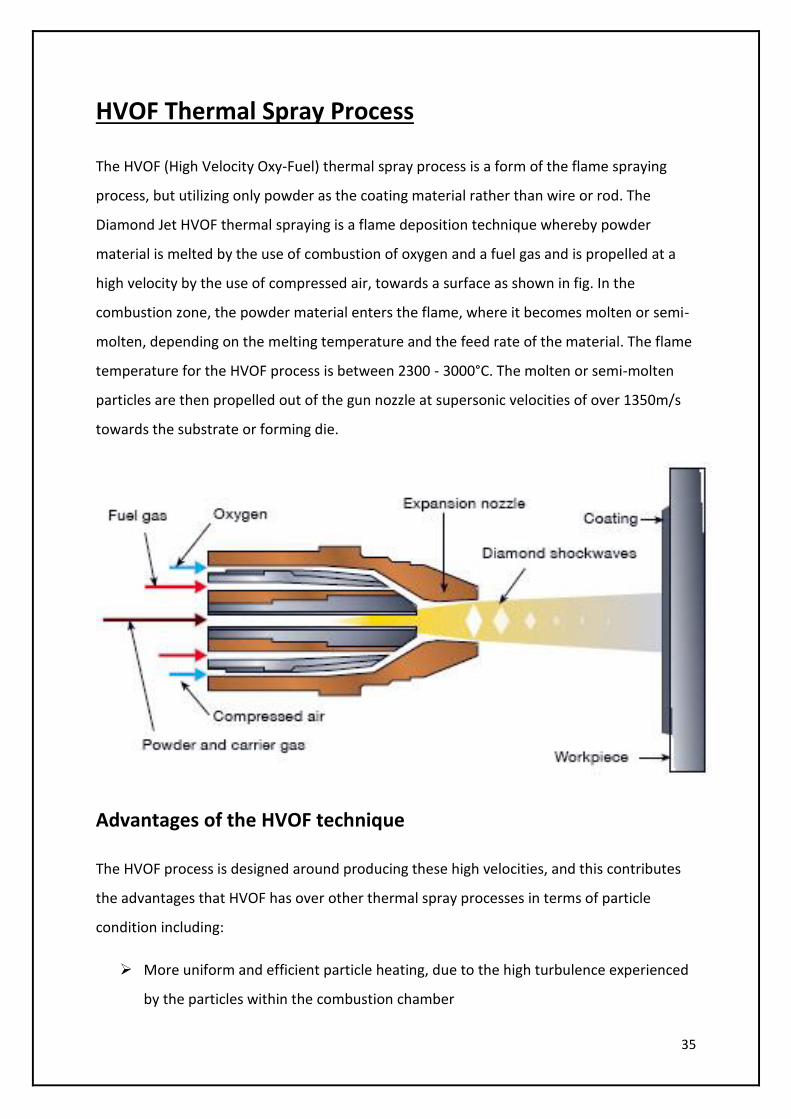
HVOF Thermal Spray Process
The HVOF (High Velocity Oxy-Fuel) thermal spray process is a form of the flame spraying
process, but utilizing only powder as the coating material rather than wire or rod. The
Diamond Jet HVOF thermal spraying is a flame deposition technique whereby powder
material is melted by the use of combustion of oxygen and a fuel gas and is propelled at a
high velocity by the use of compressed air, towards a surface as shown in fig. In the
combustion zone, the powder material enters the flame, where it becomes molten or semi-
molten, depending on the melting temperature and the feed rate of the material. The flame
temperature for the HVOF process is between 2300 - 3000°C. The molten or semi-molten
particles are then propelled out of the gun nozzle at supersonic velocities of over 1350m/s
towards the substrate or forming die.
Advantages of the HVOF technique
The HVOF process is designed around producing these high velocities, and this contributes
the advantages that HVOF has over other thermal spray processes in terms of particle
condition including:
More uniform and efficient particle heating, due to the high turbulence experienced
by the particles within the combustion chamber
36
Much shorter exposure time in flight due to the high particle velocities
Lower surface oxidation due to short particle exposure time compared to other
thermal spraying techniques
Reduced mixing with ambient air once jet and particles leave the gun
Lower ultimate particle temperatures compared to other processes such as plasma
or arc guns, as the these processes operate at temperatures of 16000 and 6000°C as
opposed to 3000°C in the HVOF (oxygen/propylene mixture) process
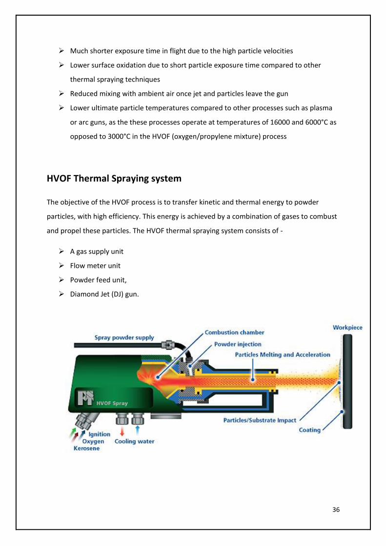
HVOF Thermal Spraying system
The objective of the HVOF process is to transfer kinetic and thermal energy to powder
particles, with high efficiency. This energy is achieved by a combination of gases to combust
and propel these particles. The HVOF thermal spraying system consists of -
A gas supply unit
Flow meter unit
Powder feed unit,
Diamond Jet (DJ) gun.
37
HVOF Spraying Procedure:
The procedure mainly consist of 4 steps:
Surface Preparation
Pre-Heat treatment
Spraying Process
Post heat treatment
Surface Preparation:
Cleaning is generally carried out by eroding the surface by a harder material, which is with
the grit (sand) blasting unit. Surface treatment has proved to provide sufficient bond
strengths between the deposit material and the receiving substrate. It increases residual
stress by very little amount but decreases thermal stress.
Pre-heat Treatment
Moisture build up on the substrate surface may be removed by exposing the surface to a
high temperature, a process known as pre-heat treating. Pre-heating the substrate may
reduce or elevate thermal stresses, dependent on the exposure temperature. The pre-heat
temperature for a steel substrate is usually within the range of 90 to 150°C, but a pre-heat
temperature of 450°C reduces greater amounts of residual stress built up m WC-Co
coatings, compared to temperatures below 150°C. Pre-heating is carried out by igniting the
gun (with a flint lighter), and heating the substrate with the guns’ flame, up to the desired
pre-heat temperature prior to deposition.
Spraying Process
First the WC-Co powder is fed in the hopper of powder feed assembly. The required nozzles
are cleaned and the gas pressures are set to get the required flow rates. Then the gun is
ignited and air flow rate is set to 325LPM. The spraying distance is controlled by a linear
motor, which also controls the deposition rate and thickness.

38
Tungsten Carbide-Cobalt Spray Parameters
Oxygen pressure (Bar) 10.3
Oxygen flow (LPM) 265
Propylene pressure (Bar) 6.9
Propylene flow (LPM) 73.0
Air pressure (Bar) 5.2
Air flow (LPM) 325
Nitrogen pressure (Bar) 12.1
Nitrogen Flow (LPM) 325
Spray distance (mm) 200
Powder feed rate (g/min) 38
Post heat Treatment
The post-heat treatment is carried out in the furnace under a nitrogen atmosphere. Post-
heat treatment of WC-Co components is used for to reduce the residual stress that had built
up during spraying. Post-heat treatment has been proved as an effective stress relief
process, where tungsten carbide-cobalt coatings or spray-formed components are elevated
to temperatures of 650°C.
In order to spray-form thick tungsten carbide cobalt (WC-Co) components, certain problems
have to be overcome More specifically these problems include minimizing residual stresses
(which cause shape distortion in the components), therefore maintaining the integrity of the
deposit on a microstructural scale. So residual stress variation with respect to different
parameters have been studied. For the measurement of residual stress we use Clyne’s
method.
39
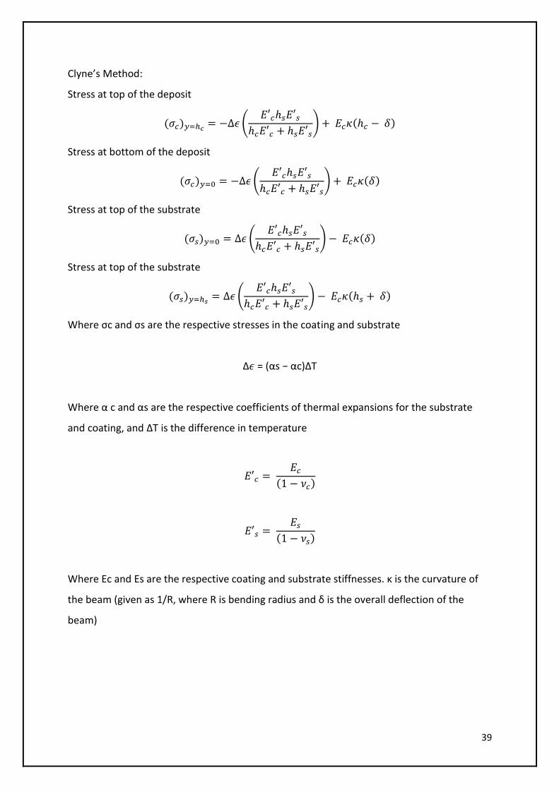
Clyne’s Method:
Stress at top of the deposit
(𝜎𝑐)𝑦=ℎ𝑐= −Δ𝜖 (
𝐸′𝑐ℎ𝑠𝐸′𝑠
ℎ𝑐𝐸′𝑐 + ℎ𝑠𝐸′𝑠) + 𝐸𝑐𝜅(ℎ𝑐 − 𝛿)
Stress at bottom of the deposit
(𝜎𝑐)𝑦=0 = −Δ𝜖 (𝐸′𝑐ℎ𝑠𝐸′𝑠
ℎ𝑐𝐸′𝑐 + ℎ𝑠𝐸′𝑠) + 𝐸𝑐𝜅(𝛿)
Stress at top of the substrate
(𝜎𝑠)𝑦=0 = Δ𝜖 (𝐸′𝑐ℎ𝑠𝐸′𝑠
ℎ𝑐𝐸′𝑐 + ℎ𝑠𝐸′𝑠) − 𝐸𝑐𝜅(𝛿)
Stress at top of the substrate
(𝜎𝑠)𝑦=ℎ𝑠= Δ𝜖 (
𝐸′𝑐ℎ𝑠𝐸′𝑠
ℎ𝑐𝐸′𝑐 + ℎ𝑠𝐸′𝑠) − 𝐸𝑐𝜅(ℎ𝑠 + 𝛿)
Where σc and σs are the respective stresses in the coating and substrate
Δ𝜖 = (αs − αc)ΔΤ
Where α c and αs are the respective coefficients of thermal expansions for the substrate
and coating, and ΔT is the difference in temperature
𝐸′𝑐 = 𝐸𝑐
(1 − 𝜈𝑐)
𝐸′𝑠 = 𝐸𝑠
(1 − 𝜈𝑠)
Where Ec and Es are the respective coating and substrate stiffnesses. κ is the curvature of
the beam (given as 1/R, where R is bending radius and δ is the overall deflection of the
beam)
40
41
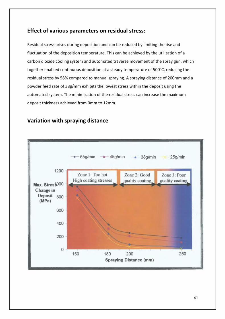
Effect of various parameters on residual stress:
Residual stress arises during deposition and can be reduced by limiting the rise and
fluctuation of the deposition temperature. This can be achieved by the utilization of a
carbon dioxide cooling system and automated traverse movement of the spray gun, which
together enabled continuous deposition at a steady temperature of 500°C, reducing the
residual stress by 58% compared to manual spraying. A spraying distance of 200mm and a
powder feed rate of 38g/mm exhibits the lowest stress within the deposit using the
automated system. The minimization of the residual stress can increase the maximum
deposit thickness achieved from 0mm to 12mm.
Variation with spraying distance
42
At smaller coating distances the residual stress is higher which gives rise to higher cooling
stresses. Also the variation is higher for low distance.
At higher distances the stresses are further reduced but the coating quality is poor due to
increased flight timings of the particles which results in cooling and poor adhesion of
particles to the substrate.
Stress values are significantly lower at distance 200mm and the deposition temperature
remains constant at 500°C
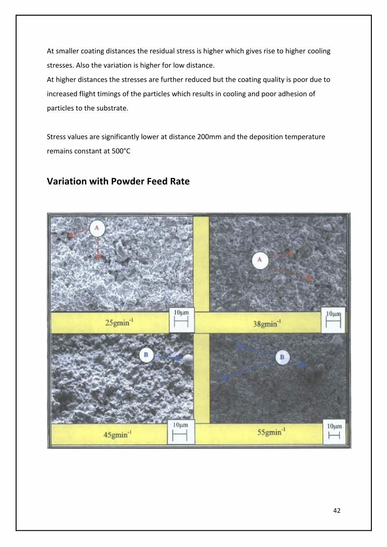
Variation with Powder Feed Rate
43
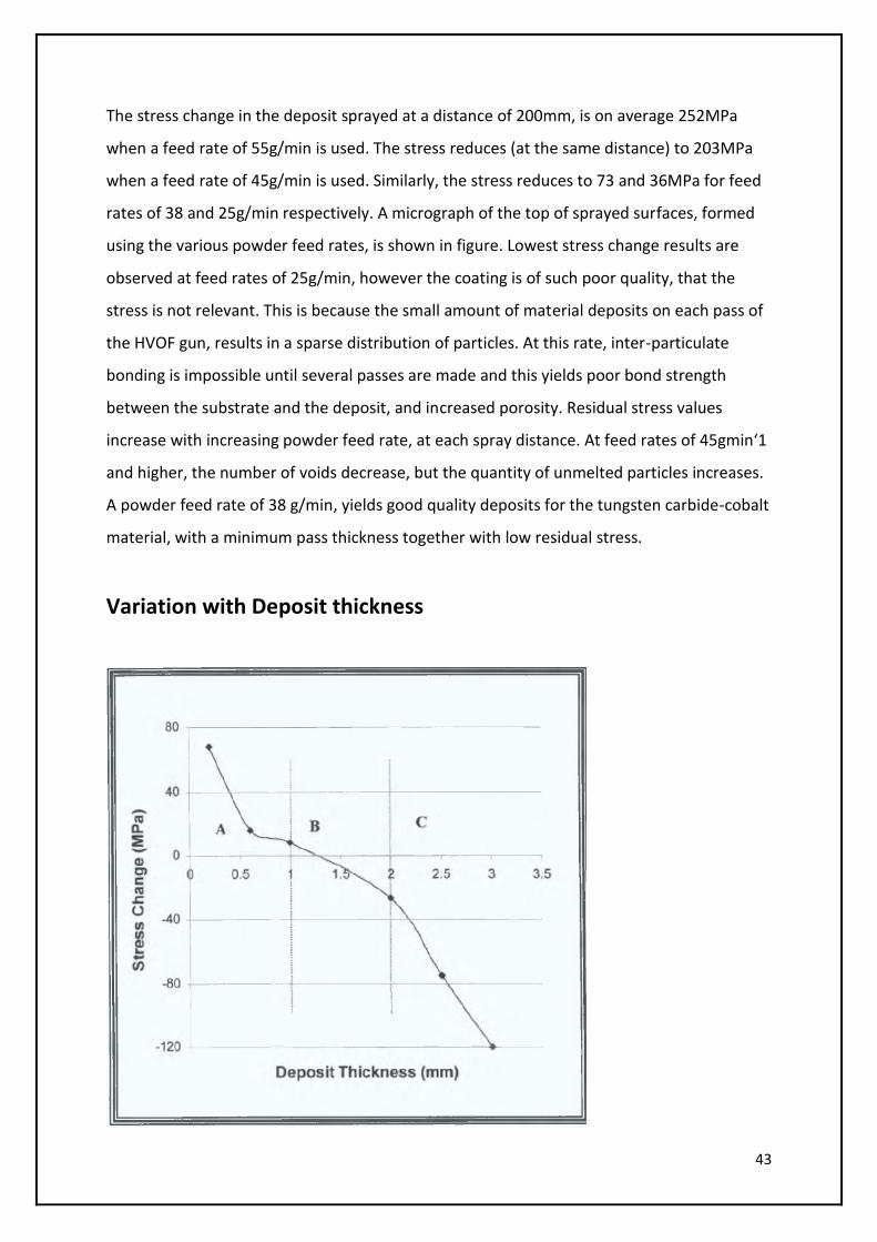
The stress change in the deposit sprayed at a distance of 200mm, is on average 252MPa
when a feed rate of 55g/min is used. The stress reduces (at the same distance) to 203MPa
when a feed rate of 45g/min is used. Similarly, the stress reduces to 73 and 36MPa for feed
rates of 38 and 25g/min respectively. A micrograph of the top of sprayed surfaces, formed
using the various powder feed rates, is shown in figure. Lowest stress change results are
observed at feed rates of 25g/min, however the coating is of such poor quality, that the
stress is not relevant. This is because the small amount of material deposits on each pass of
the HVOF gun, results in a sparse distribution of particles. At this rate, inter-particulate
bonding is impossible until several passes are made and this yields poor bond strength
between the substrate and the deposit, and increased porosity. Residual stress values
increase with increasing powder feed rate, at each spray distance. At feed rates of 45gmin‘1
and higher, the number of voids decrease, but the quantity of unmelted particles increases.
A powder feed rate of 38 g/min, yields good quality deposits for the tungsten carbide-cobalt
material, with a minimum pass thickness together with low residual stress.
Variation with Deposit thickness
44
The variation of stress with deposit thickness is non-linear. It can be divided into 3 zones – In
zone-A there is a sharp decrease with deposit thickness upto 1mm. the stress decreases at
lower rate at thickness 1mm to 2 mm. At greater thickness, the stress again decreases at
higher rate. A deposit thickness of 1.2mm produces a stress free deposit so it is used in the
process.
45
Brazing
Brazing of a ceramic or a carbide to a substrate using filler metal is often used for different
applications. In the brazing processes, the differential expansion and contraction between the
ceramic and the metal, and the resulting effect on the joint properties, becomes a major concern.
Brazing is the preferred method of joining the carbide and its supporting mass of steel. Further,
silver based alloys popular due to their low melting temperatures, excellent Wetting
characteristics and good mechanical properties. These alloys generally contain Cu, Zn, Cd, Ni and
Mn, and operate at temperatures in the range 640—840° C. Copper-based brazing alloys are also
used, considering the high price of silver. These alloys typically contain Cu, Ni, Mn, Si and Zn, and
operate at temperatures between 870—1100° C. One of the requirements of the braze filler is
that it is of sufficient thickness so that it can absorb the stresses introduced due to the difference
in the expansion coefficient of steel and tungstencarbide. A silver-base alloy, Ag71Cu27Ti2, is used
as the filler metal to brazeSi3N4 to an Inconel base metal. The bonding mechanism between the
two is attributed to the diffusion of Ag and Cu alloy into the grain boundaries of Inconel. This
diffusionresults in mechanical anchoring.
Sintering
Sintering process is used to create the coating composition (Hardfacing Material + Binder Phase)
apart from being used to apply the coating composition onto the substrate surface. Sintering is a
method for creating objects from powders, including metal and ceramic powders.It is based on
atomic diffusion. Diffusion occurs in any material above absolute zero, but it occurs much faster
at higher temperatures. In most sintering processes, the powdered material is held in a mould
and then heated to a temperature below the melting point. The atoms in the powder particles
diffuse across the boundaries of the particles, fusing the particles together and creating one
solid piece. Because the sintering temperature does not have to reach the melting point of the
material, sintering is often chosen as the shaping process for materials with extremely high
melting points such as tungsten and molybdenum.
Sintering is traditionally used for manufacturing ceramic objects but finds applications in
almost all fields of industry. The study of sintering and of powder-related processes is
known as powder metallurgy.
46
Hardfacing Inconel with Tungsten Carbide Using Sintering Process
A method of applying a particulate material to a substrate includes:
Removing impurities from the surface of the substrate
Forming a coating composition having particles of the bonding material and the
particulate material
Applying the coating composition to the substrate surface, thus creating a diffusion
bond between the substrate, bonding material and the particulate material.
This generates a continuous interface between the substrate surface and particulate
material such that the change in mechanical properties between the substrate and the
particulate material occurs in a direction normal to the plane of the substrate surface. This
minimizes the residual strain and coefficient of thermal expansion mismatch between the
substrate and particulate material. The surfaces of the particulate materials are chemically
wetted by the particles of the bonding material.
The impurities are removed from the substrate surface by thermal decomposition, chemical
decomposition, electrolytic decomposition, oblation by ions (using high energy beams),
ultrasonic spray fluxing. The coating composition is applied to the substrate surface by
Sintering Process.
The particulate material can be of a material like tungsten carbide, titanium carbide,
vanadium carbide, titanium diboride, hafnium carbide, molybdenum carbide, diamond
hafnium diboride, zirconium carbide, chrome carbide, tantalum carbide, etc or a
combination of the above. The substrate used is Inconel.
Good interfacial bonding is desired between tungsten carbide and the nickel brazes to avoid
tungsten carbide pull-outs during actual service of the material. As mentioned earlier, good
wettability is the key to the problem. Wettability can be tested by sintering a tungsten
carbide-nickel braze mixture compact above the liquid temperature of the braze alloy
(Where the nickel braze alloy is present as a liquid phase only). Poor Wettability results in
swelling of the compact and liquid exuding from the compact. The exuded liquid appears as
47
small spherical balls on the surface of the compact. This processing step helps in isolating
the suitable braze alloys for further processing.
A tungsten carbide-nickel braze composite can be developed in two different Ways. The first
method involves sintering a mixture of tungsten carbide-nickel base mixture above the
liquids temperature of the nickel braze to allow for densification of the material in presence
of a liquid phase. The limitation with this process is that the effect of relative size and
density of the nickel braze and the tungsten carbide becomes prominent during mixing and
infiltration. The nickel braze powders are generally available in the coarser size range, as
opposed to tungsten carbide which is preferred in finer sizes to enhance the mechanical
properties. This can lead to segregation during mixing. More critical are the sintering
problems associated with the powder size. On melting, nickel braze leaves behind a large
pore (site of its original occupation), and fill up smaller ones. This would lead to poor
densification on completion of the sintering process.
The other method involves fabrication of tungsten carbide-nickel braze composite by
selective infiltration of tungsten carbide porous forms by nickel braze liquid. Nickel brazes
and tungsten carbide, in the form of tape-cast sheets, are stacked one over the other and
sintered above the liquids temperature of the nickel brazes. Densification is achieved
through capillary action and gravity-induced infiltrations of nickel braze liquid into the
tungsten carbide sheet. This method is not limited by nickel braze particle size, as it is liquid
prior to infiltration. Another advantage with this
Design is that homogenous composite can be developed by controlling the pore size of the
tungsten carbide tape-cast sheet.
The bonding process requires the nickel braze alloy as a cementing agent between the
Inconel substrate and the tungsten carbide. The liquid should be minimized at the interfacial
joint between the braze alloy and the substrate to reduce the occurrence of Weak regions
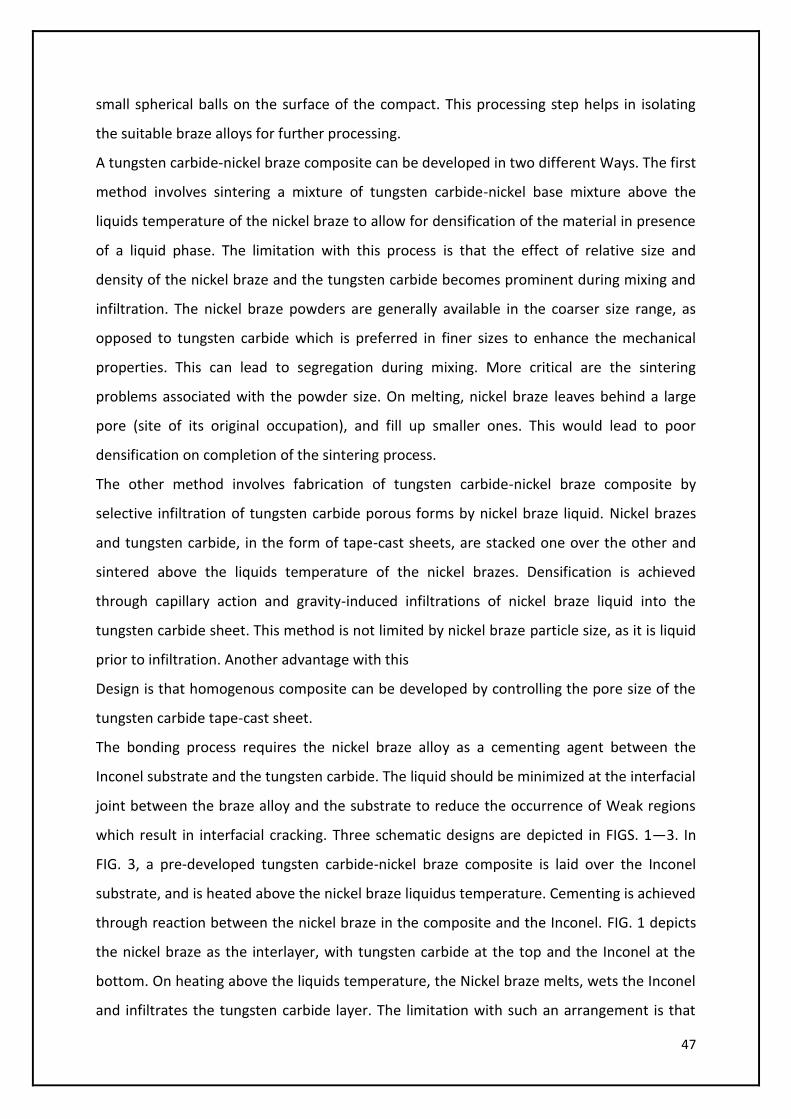
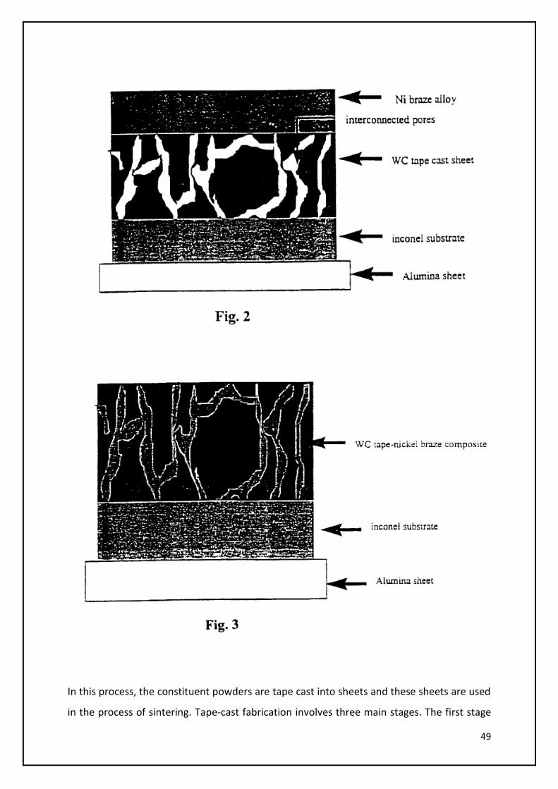
which result in interfacial cracking. Three schematic designs are depicted in FIGS. 1—3. In
FIG. 3, a pre-developed tungsten carbide-nickel braze composite is laid over the Inconel
substrate, and is heated above the nickel braze liquidus temperature. Cementing is achieved
through reaction between the nickel braze in the composite and the Inconel. FIG. 1 depicts
the nickel braze as the interlayer, with tungsten carbide at the top and the Inconel at the
bottom. On heating above the liquids temperature, the Nickel braze melts, wets the Inconel
and infiltrates the tungsten carbide layer. The limitation with such an arrangement is that
48
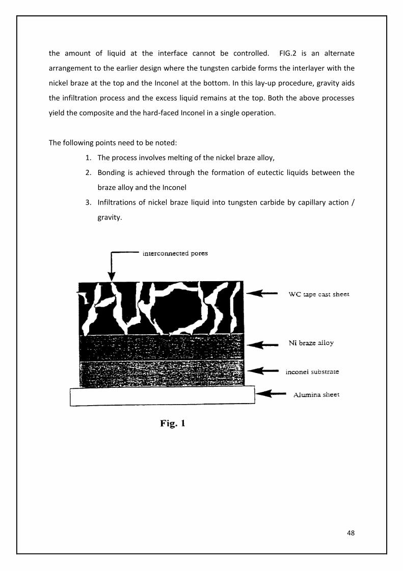
the amount of liquid at the interface cannot be controlled. FIG.2 is an alternate
arrangement to the earlier design where the tungsten carbide forms the interlayer with the
nickel braze at the top and the Inconel at the bottom. In this lay-up procedure, gravity aids
the infiltration process and the excess liquid remains at the top. Both the above processes
yield the composite and the hard-faced Inconel in a single operation.
The following points need to be noted:
1. The process involves melting of the nickel braze alloy,
2. Bonding is achieved through the formation of eutectic liquids between the
braze alloy and the Inconel
3. Infiltrations of nickel braze liquid into tungsten carbide by capillary action /
gravity.
49
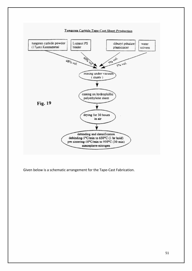
In this process, the constituent powders are tape cast into sheets and these sheets are used
in the process of sintering. Tape-cast fabrication involves three main stages. The first stage

50
involves the selection of a suitable binder system that is compatible with the powders and
yields a flexible homogenous sheet. In the second stage, the composition of the sheet and
fabrication routes should be considered to allow for maximum solids loading (i.e., volume
fraction of tungsten carbide) without sacrificing the flexibility and the uniformity of the
sheets. For generation of a tape-cast sheet, the additive system primarily comprises binder,
plasticizer, solvent, and a surfactant (if required). The binder provides the necessary
bonding between the powder particles which facilitates room temperature handling. The
plasticizer is used to induce flexibility in the sheet which allows it to conform to substrates
with a slight curvature. Surfactant is added to disperse agglomerates adherent due to Weak
van der Waal forces or presence of moisture. One important aspect of the additive system is
that its residual ash content needs to below. This is critical for systems like tungsten carbide
which require close carbon control.
The binder system employed needs to blend in with the tungsten carbide powder to provide
for homogenous tape-cast sheets. In this process, Lupasol PS is used as the binding agent.
The casting substrate is also of crucial importance as it defines the surface finish and the
thickness of the tape-cast sheet. This essentially dictates the surface smoothness of the final
composite. Desirable properties of the casting surface are:
Smooth glassy finish and Poor wettability so as to ensure easy release of the sheet on
drying
Porous surface as this decreases the drying time and higher volume fractions of the
tungsten carbide can be achieved
A Hydrophilic polythene sheet is used as it conforms to the above mentioned factors.
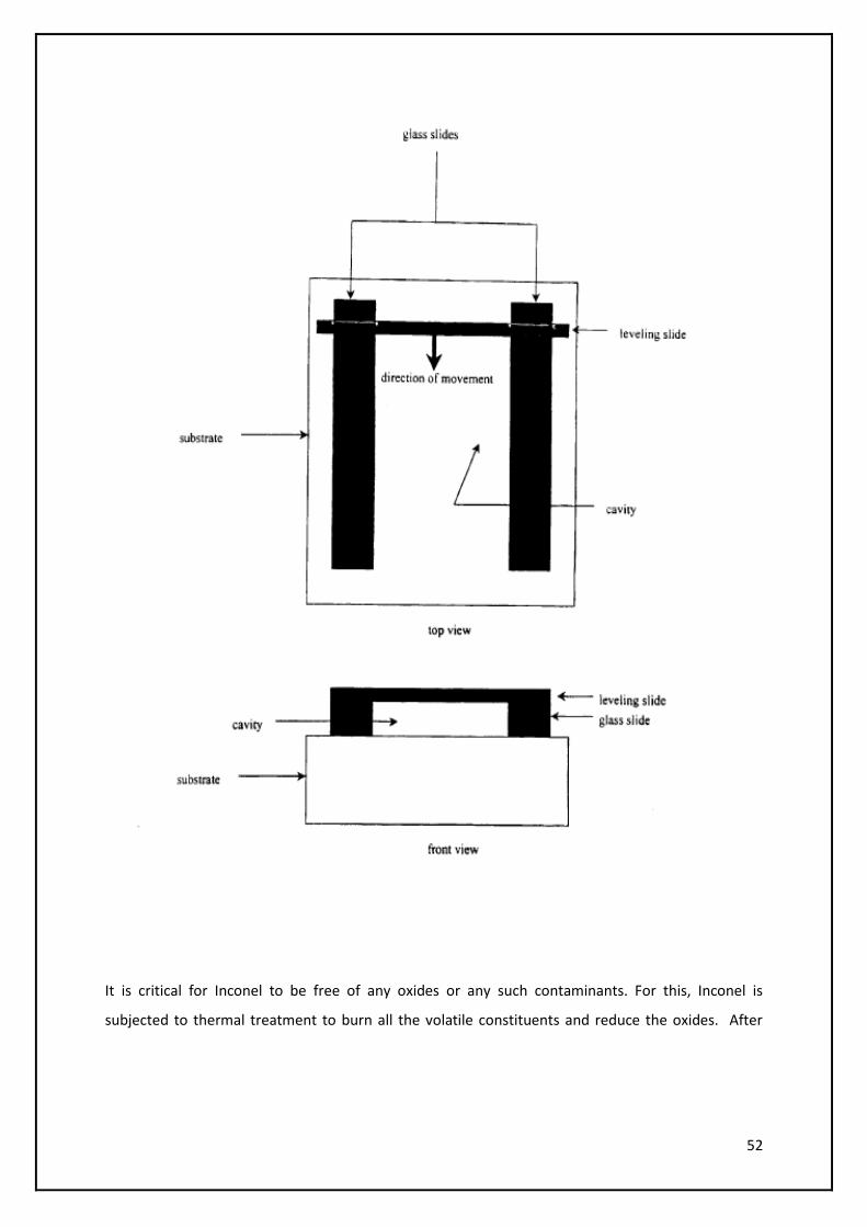
The thickness of the sheet can be controlled by two Plexiglass slides which are mounted on
the two ends along the width of the substrate and extended parallel along the length
direction. This forms a cavity which holds the slurry. The thickness of sheet can be
controlled by the thickness of the glass slides. The pores present in the casting substrate
remove water by capillary action and consequently increases the solids loading through
particle rearrangement.
51
Given below is a schematic arrangement for the Tape-Cast Fabrication.
52
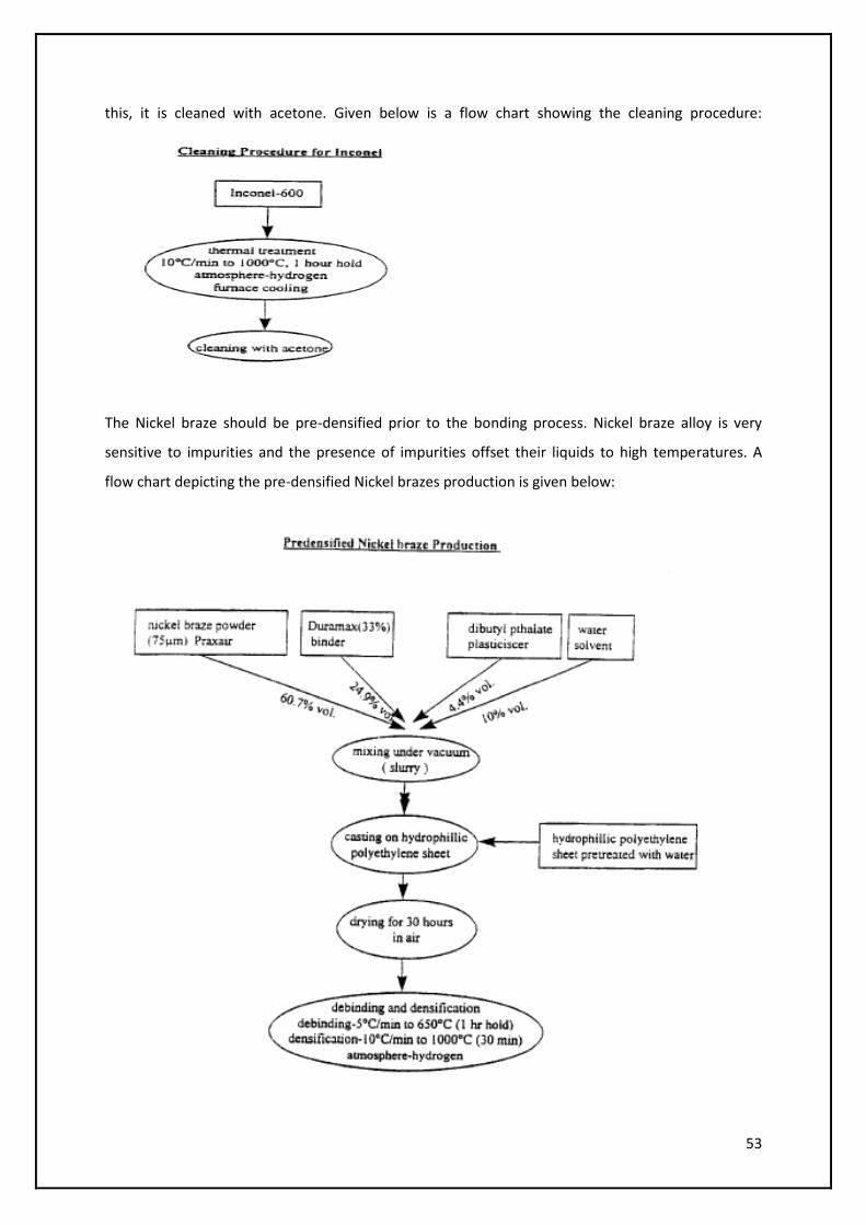
It is critical for Inconel to be free of any oxides or any such contaminants. For this, Inconel is
subjected to thermal treatment to burn all the volatile constituents and reduce the oxides. After
53
this, it is cleaned with acetone. Given below is a flow chart showing the cleaning procedure:
The Nickel braze should be pre-densified prior to the bonding process. Nickel braze alloy is very
sensitive to impurities and the presence of impurities offset their liquids to high temperatures. A
flow chart depicting the pre-densified Nickel brazes production is given below:

54
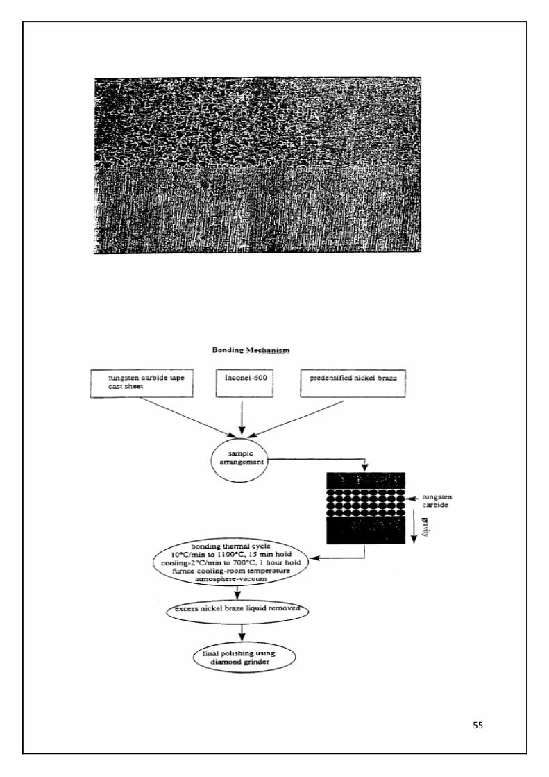
Using the arrangement as shown in Fig.1 gives the final micro-structure as show below:
Here, even though the sample is fully dense, a crack persists through the interface. Also, excess
liquid is present at the interface and this causes the delamination to occur during the cooling
operation. During cooing, the tungsten carbide-nickel braze composite, the excess liquid and Inconel
undergo shrinkage. The Shrinkage rate is slower for the coating as compared to the excess liquid due
to the presence of tungsten carbide. This results in a restrained shrinkage. This influences the crack
to occur at the composite coating and the excess nickel braze liquid interface and leads to
delamination.
Hence, an arrangement as shown in Fig. 2 is used. Here, any excess liquid which is present
subsequent to infiltration is left on top and can be removed and reused. The Nickel braze acts like a
liquid reservoir on melting. Moreover, the infiltration of nickel braze is aided by capillary forces and
gravity. Once the full infiltration is achieved, the nickel braze liquid reacts with the Inconel to provide
interfacial bonding. This controls the liquid at the interface and thus, minimizes the chances of
interfacial cracking. The resulting product from this arrangement is as follows:
55

56
Chromium Carbide: An Alternative
As discussed earlier even though Tungsten carbide has the best optimum mix of
toughness, hardness and other such mechanical properties, it still has some drawbacks.
Being a high density material, it tends to sink in to the base metal, especially the lower
density metals under the impact of continuous high loads. Apart from that, in a subsea
system, corrosion due to chlorine and fluorine is a major concern. Even though Tungsten
Carbide is corrosion resistant to most extremely corrosive alkaline and acidic media, it is
susceptible to chlorine corrosion at elevated temperatures and susceptible to fluorine
corrosion at room temperatures. Also, in cases where Tungsten Carbide has been used as
the hardfacing agent, formation of brittle intermetallic phases called Eta Carbides was
observed.
Eta phase is a carbon deficient form of tungsten carbide that results in
a harder, more brittle cemented carbide part. Insufficient carbon levels are generally the
result of improper formulation of the carbide powder, long term exposure of unsintered
parts to the atmosphere, or poor control of sintering conditions. Eta phase is generally
considered to be harmful to the performance of cemented carbide parts. Keeping these
factors in mind, a viable alternative to tungsten carbide which offers similar quality, less
costly and more corrosion resistance was explored.
Chromium carbide is one of the best known anti-corrosion materials. Chromium is
used as an additive in various cases where corrosion resistance is an important criterion.
The gate seat arrangement inside the valve is exposed to a corrosive environment where
chlorine, fluorine and hydrogen sulphide are the major players. Using chromium carbide in
these extremely corrosive places would enhance the corrosion resistance of the system.
Also, Chromium carbide has a density of 6.8-7.0 g/cc. As inconel has a density of 8 g/cc
and most base metals have a density less than 8, this ensures that Chromium Carbide does
not sink into the matrix at continuous high loads. Also, no brittle intermetallic phases (Eta
Carbides) were observed in the case of Chromium. From cost point of view, using Chromium
carbide is cheaper. Hence, in suitable conditions if not all, Chromium Carbide can be used as
an alternative to Tungsten Carbide.
57
58
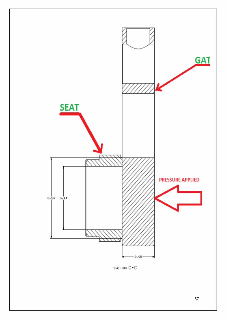
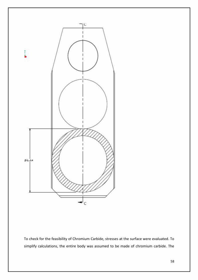
To check for the feasibility of Chromium Carbide, stresses at the surface were evaluated. To
simplify calculations, the entire body was assumed to be made of chromium carbide. The
59
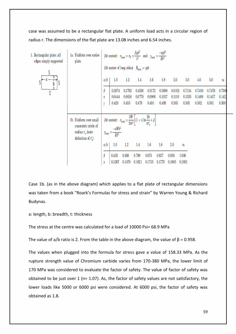
case was assumed to be a rectangular flat plate. A uniform load acts in a circular region of
radius r. The dimensions of the flat plate are 13.08 inches and 6.54 inches.
Case 1b. (as in the above diagram) which applies to a flat plate of rectangular dimensions
was taken from a book “Roark’s Formulas for stress and strain” by Warren Young & Richard
Budynas.
a: length, b: breadth, t: thickness
The stress at the centre was calculated for a load of 10000 Psi= 68.9 MPa
The value of a/b ratio is 2. From the table in the above diagram, the value of β = 0.958.
The values when plugged into the formula for stress gave a value of 158.33 MPa. As the
rupture strength value of Chromium carbide varies from 170-380 MPa, the lower limit of
170 MPa was considered to evaluate the factor of safety. The value of factor of safety was
obtained to be just over 1 (n= 1.07). As, the factor of safety values are not satisfactory, the
lower loads like 5000 or 6000 psi were considered. At 6000 psi, the factor of safety was
obtained as 1.8.
60
These values were obtained for the worst case of the entire slab of the gate valve being
made of chromium carbide. However, chromium carbide will be only at the surface and the
body of the slab is made of inconel.
Hence, it can be suggested that chromium carbide is a viable alternative to tungsten carbide
at lower loads of 6000 psi. FMC has a valve series of 120 plus which are rated to be operated
at 5000-6000 psi. Hence, chromium carbide can be used at much lower loads.
61
References
1. Sandvik Carbide Report- Understanding Cemented Carbide
2. Designer’s Guide to Tungsten carbide- General Carbide
3. Hardfacing Guide by Lincoln electrics
4. US Patent No. 4173457: Hardfacing Composition of Nickel bonded sintered
Chromium Carbide particles and tools Hardfaced thereof
5. US Patent No. 6436470 : Method of Applying a Hardfacing Material to a Substrate
6. Hardfacing by welding- M. Riddihough
7. Roark’s Formulas for Stress and Strain by Warren Young & Richard Budynas
8. General Carbide grade Specifications
9. www.superalloys.com
10. www.generalcarbide.com
11. www.specialmetals.com
12. Economics of Hardfacing- Postle Industries