FINAL REPORT EVALUATION OF ANODES FOR · PDF fileEVALUATION OF ANODES FOR GALVANIC CATHODIC...
36
FINAL REPORT EVALUATION OF ANODES FOR GALVANIC CATHODIC PREVENTION OF STEEL CORROSION IN PRESTRESSED CONCRETE PILES IN MARINE ENVIRONMENTS IN VIRGINIA Gerardo G. Clemeña, Ph.D. Principal Research Scientist Virginia Transportation Research Council Donald R. Jackson, P.E. Office of Technology Applications Federal Highway Administration (The opinions, findings, and conclusions expressed in this report are those of the authors and not necessarily those of the sponsoring agencies.) Virginia Transportation Research Council (A Cooperative Organization Sponsored Jointly by the Virginia Department of Transportation and the University of Virginia) In Cooperation with the U. S. Department of Transportation Federal Highway Administration Charlottesville, Virginia July 1999 VTRC 00-R3
Transcript of FINAL REPORT EVALUATION OF ANODES FOR · PDF fileEVALUATION OF ANODES FOR GALVANIC CATHODIC...

FINAL REPORT
EVALUATION OF ANODES FOR GALVANIC CATHODIC PREVENTION OF STEEL CORROSION IN PRESTRESSED CONCRETE PILES
IN MARINE ENVIRONMENTS IN VIRGINIA
Gerardo G. Clemeña, Ph.D. Principal Research Scientist
Virginia Transportation Research Council
Donald R. Jackson, P.E. Office of Technology Applications Federal Highway Administration
(The opinions, findings, and conclusions expressed in this report are those of the authors and not necessarily
those of the sponsoring agencies.)
Virginia Transportation Research Council (A Cooperative Organization Sponsored Jointly by the
Virginia Department of Transportation and the University of Virginia)
In Cooperation with the U. S. Department of Transportation
Federal Highway Administration
Charlottesville, Virginia
July 1999 VTRC 00-R3

ii
Copyright 1999 by the Commonwealth of Virginia.

iii
ABSTRACT Many of the major highway crossings over coastal waters in the Hampton area of Virginia are supported by prestressed concrete piles, some of which are showing signs of reinforcement corrosion. Grout jacketing alone is an inadequate protection against corrosion and should be supplemented with cathodic protection (CP). Recent advances in the development of anodes make it practical to use galvanic CP to protect these types of concrete bridge components.
Five anode systems were tested on several piles of the Willoughby Bay Bridge on I-64 in Norfolk, Virginia: (1) an aluminum-zinc-indium alloy applied by arc-spraying on the concrete, (2) a zinc foil with conductive adhesive backing, (3) a system of zinc mesh and grout jacket, (4) a system of zinc mesh and compression panels, and (5) a bulk zinc. During the first 14 months of operation, the protection current outputs of these anodes, the closed-circuit potentials of the steel at various elevations on the piles, and the extent of polarization imparted were measured. Attempts to project the life of these anodes and compare the costs of using them were also made. The authors conclude that the zinc mesh and grout jacket anode system is the best for applying CP at the tidal and splash zones and the aluminum-zinc-indium anode is the best for use at any elevation above the splash zone.
FINAL REPORT
EVALUATION OF ANODES FOR GALVANIC CATHODIC PREVENTION OF STEEL CORROSION IN PRESTRESSED CONCRETE PILES
IN MARINE ENVIRONMENTS IN VIRGINIA
Gerardo G. Clemeña, Ph.D. Principal Research Scientist
Virginia Transportation Research Council
Donald R. Jackson, P.E. Office of Technology Applications Federal Highway Administration
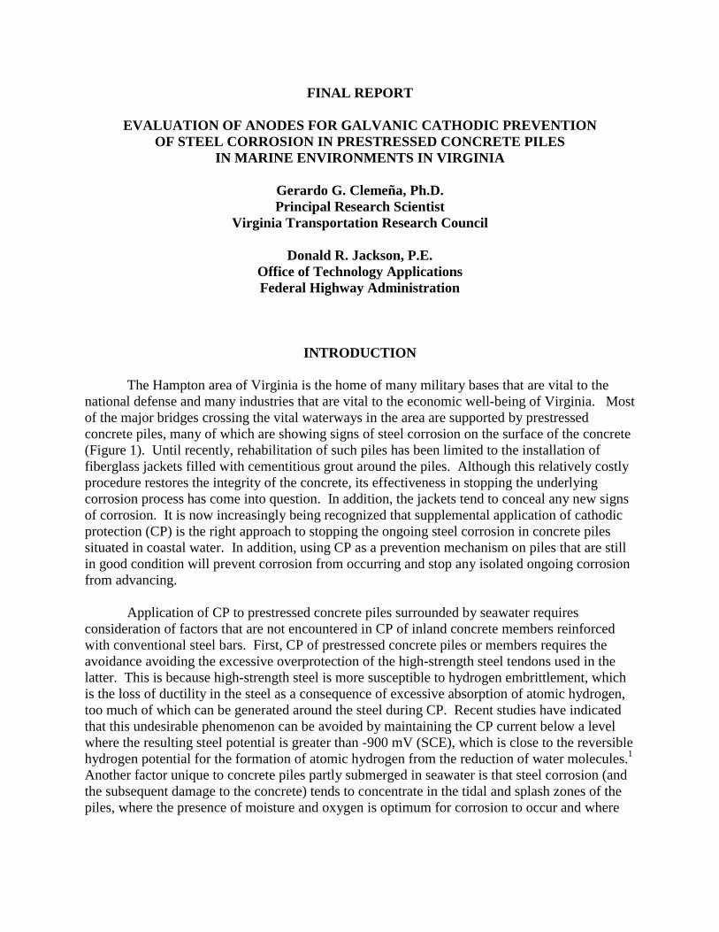
INTRODUCTION The Hampton area of Virginia is the home of many military bases that are vital to the national defense and many industries that are vital to the economic well-being of Virginia. Most of the major bridges crossing the vital waterways in the area are supported by prestressed concrete piles, many of which are showing signs of steel corrosion on the surface of the concrete (Figure 1). Until recently, rehabilitation of such piles has been limited to the installation of fiberglass jackets filled with cementitious grout around the piles. Although this relatively costly procedure restores the integrity of the concrete, its effectiveness in stopping the underlying corrosion process has come into question. In addition, the jackets tend to conceal any new signs of corrosion. It is now increasingly being recognized that supplemental application of cathodic protection (CP) is the right approach to stopping the ongoing steel corrosion in concrete piles situated in coastal water. In addition, using CP as a prevention mechanism on piles that are still in good condition will prevent corrosion from occurring and stop any isolated ongoing corrosion from advancing.
Application of CP to prestressed concrete piles surrounded by seawater requires consideration of factors that are not encountered in CP of inland concrete members reinforced with conventional steel bars. First, CP of prestressed concrete piles or members requires the avoidance avoiding the excessive overprotection of the high-strength steel tendons used in the latter. This is because high-strength steel is more susceptible to hydrogen embrittlement, which is the loss of ductility in the steel as a consequence of excessive absorption of atomic hydrogen, too much of which can be generated around the steel during CP. Recent studies have indicated that this undesirable phenomenon can be avoided by maintaining the CP current below a level where the resulting steel potential is greater than -900 mV (SCE), which is close to the reversible hydrogen potential for the formation of atomic hydrogen from the reduction of water molecules.1 Another factor unique to concrete piles partly submerged in seawater is that steel corrosion (and the subsequent damage to the concrete) tends to concentrate in the tidal and splash zones of the piles, where the presence of moisture and oxygen is optimum for corrosion to occur and where
2
Figure 1. Concrete Piles in the Hampton Area with Visible Signs of Steel Corrosion most of the CP current needs to be distributed. Fortuitously, these zones are relatively wetter and, therefore, more electrically conductive than the concrete at the remaining areas of a pile. Under these circumstances, the galvanic mode of CP is particularly suitable and more appropriate than the impressed-current mode of CP that is commonly used on inland concrete bridge decks and piers. In this latter mode, the protection current, a direct current (DC), flowing from the embedded steel to an anode is supplied by an external source, which must be inspected regularly by site visits or remote monitoring and maintained.
In contrast, galvanic CP relies on the difference in the natural electrical potentials of the steel and a relatively more active metal to provide the current needed to protect the reinforcing steel. The anodic metals typically used in galvanic CP of steel include magnesium (Mg), zinc (Zn), aluminum (Al), and alloys of these metals. These metals are more electronegative or active than steel and, therefore, act as anodes when electrically coupled to steel and immersed in an electrolyte.2,3 Magnesium is used more often in soil and fresh water, and zinc and aluminum are used more often in sea and brackish waters. When one of these metals is coupled to steel, the characteristic voltage difference between them causes a characteristic amount of electrons to flow from that anode to the steel, thereby protecting the latter from corrosion while sacrificing the former. Therefore, once the anode is properly selected, the CP current is, in essence, preset and will not exceed that level until the anode is consumed and needs to be replenished. In addition, the weight of the anode can be optimized to provide maximum service life. With only the electrical wiring between the anodes and the structural steel to be maintained and the anodes to be replaced, galvanic CP offers many advantages over impressed-current CP.
Recently, the use of a zinc coating, which is thermally sprayed on concrete, as a sacrificial anode for galvanic CP of atmospherically exposed concrete bridge piles in marine environments was tested on concrete piles in Florida. The zinc applied in the splash zone appeared to be performing well. However, above the splash zone, where the concrete is drier,

3
the protective current produced by the zinc coating appeared to decrease with time. Subsequent laboratory tests confirmed that when concrete is dry, the protective current produced by the zinc coating tends to decrease in a short time, even after just several days.4 Further, this current reduction was considerable; in fact, the current flow was reversed when the humidity was below 40 percent and the temperature was below 32oC. This also meant that the protective current could become insufficient during the cold months of the year.
Subsequently, an aluminum-zinc-indium (Al-Zn-In) alloy with a composition of (80:20:0.2) was developed as a better alternative in a study sponsored by the Federal Highway Administration.4,5 Laboratory comparisons with the zinc coating indicated that (1) the arc-sprayed coatings of this new alloy produced relatively higher and more stable (with time) CP current, and (2) this current did not degrade at low temperatures and low humidity to the extent the current from the zinc coating did.4,5
In addition to this new alloy, another new anode became available because of the recent development of an electrically conductive hydrogel. This material can function as a coupler, both mechanically and electrically, between sheets or foils of a suitable anode and the surface of a reinforced concrete pile.6 Early tests indicated that a combination of a zinc foil and the conductive hydrogel, the Zn/hydrogel anode system, could also be a good galvanic anode for the concrete area at and above the splash zone.
Recently, two other new anode systems became available for application in galvanic CP of reinforced concrete piles. One uses expanded zinc mesh, which is secured within a cement grout/fiberglass jacket system that wraps around the piles to be protected.7 In effect, this system is a combination of the conventional grout jacket, which would restore any loss in the cross section of a concrete pile and then some, and galvanic CP, which would prevent steel corrosion in the restored pile. Since the amount of the zinc mesh used can be designed to allow the anode to last a very long time, this anode may be the most suitable for protecting a pile in the tidal zone and above the splash zone. However, this system may be relatively more expensive to install. The second anode system also uses expanded zinc mesh, which is pressed against the concrete surface (at the tidal and splash zones) with compressed panels made of recycled non-conductive materials.8 Although this system does not provide the strong protection against impact that the Zn/grout jacket does, its zinc mesh would be easy to replenish when all the zinc is consumed.
Each of these anode systems has merit. Since tests of almost all of these systems in Florida were limited, it was uncertain which system (or combination of systems) might be the most effective. In addition, because what might be most suitable for one state or region might not be suitable for another, which system was most suitable for use in the coastal areas of Virginia needed to be identified. PURPOSE AND SCOPE
Since there will soon be a need to apply galvanic CP to the hundreds of prestressed concrete piles in the Hampton area of Virginia, this investigation involved a search for an anode

4
system that would be most suitable for the climate in Virginia’s coastal areas. The objective of this investigation was to determine whether any of the recently developed anode systems was suitable and, if none was suitable, to identify the improvements needed to develop a satisfactory galvanic anode system.
Five anode systems were tested on 10 concrete piles in Norfolk, Virginia.
METHODOLOGY A test installation was designed that incorporated the anode systems listed in Table 1. The anodes and accessories were installed on test piles, the systems were activated, and the parameters that indicate the performance of the anodes were observed.
Table 1. Pile Assignments for the Anode Systems
Concrete Area Bent
Pile
Anode System
Pile Elevation Treated (m2) (ft2)
1 1-2 Al-Zn-In Splash zone and above 8.9 96 1-3 Al-Zn-In Splash zone and above 8.9 96 1-4 Zn/Hydrogel Splash zone and above 8.9 96 1-5 Zn/Hydrogel Splash zone and above 8.9 96
2 2-1 Bulk Zn (Submerged) Tidal and splash zones Unknown Al-Zn-In Splash zone and above 8.9 96 2-2 Zn/Grout Jacket Tidal and splash zones 4.1 44 Zn/Hydrogel Splash zone and above 5.9 64 2-3 Zn/Grout Jacket Tidal and splash zones 4.1 44 2-4 Zn/Compressed Panel Tidal and splash zones 4.1 44 2-5 Zn/Compressed Panel Tidal and splash zones 4.1 44 Al-Zn-In Splash zone and above 5.9 64 2-6 Al-Zn-In Splash zone and above 8.9 96
Design of the Anode Test Installation
Since funding was limited, only 10 test piles were selected for this investigation. These square prestressed concrete piles are part of two of the hundreds of bents that support the I-64 bridge over the Willoughby Bay in Norfolk, Virginia. To facilitate understanding of the behavior of the different anodes, the anodes, either alone or in combination, were assigned as indicated in Table 1 and shown on the plans in Figures 2 and 3.

5
Figure 2. Placement of Anode and Test Electrode for Bent 1
Figure 3. Placement of Anode and Electrode for Bent 2 Bent 1 is at the western end of the bridge, and approximately 0.30 m (1 ft) of the bottom
portion of the pile is immersed during high tide. Bent 2 is approximately 12 m (40 ft) to the east of Bent 1. Each pile is 0.60 m (24 in) by 0.60 m (24 in) in cross section. The water surrounding the piles is generally calm, with little or no wave action, except during storms. During high tide, half of the jacket systems and the compressed panel systems would be immersed in water; during low tide, the jacket systems would be almost totally above water.

6
A 22.7-kg (50-lb) zinc bulk anode was added to determine how much of the concrete above the waterline can be protected by a bulk anode. As illustrated in Figure 3, this anode was immersed at 0.9 m (3 ft) below the level of the water at low tide and attached to the reinforcing steel of pile 2-1.
To facilitate measurement of the degree of polarization of the reinforcing steel as a result of the CP provided by the various anodes, one to three Ag/AgCl reference electrodes were embedded in each pile (Figures 2 and 3). Pile 2-1 has three reference electrodes: one at the mean high-water level, one at approximately 0.6 m (2 ft) above the mean high-water level (both to measure the polarization effect of the bulk anode on the steel at these locations), and one slightly above the splash zone for the Al-Zn-In anode. Each of the other piles has one or two reference electrodes, depending on the anode or combination anodes used on the pile. To facilitate measurement of the current output of each anode on each pile, a 0.10 Ω resistor was installed between the anode and the steel. The lead wires from the anodes, the ground connections to the steel, and the reference electrodes were to be routed in PVC conduits (fastened on the sides of the piles) to a main junction box located at the end of the bridge.
Construction and Activation of Test Installations
In general, construction of the test installation proceeded in the following sequence:
1. installation of reference electrodes 2. electrical bonding of the prestressing tendons and installation of system negative
connections 3. preparation and cleaning of the concrete surface prior to anode application
4. application of anode
5. application of an outer protective coating over the anodes on piles 1-4, 1-5, 2-1, 2-2,
2-5, and 2-6 6. installation of test wiring, junction boxes, conduits, and main terminal box
7. activation of the systems.
Installation of the reference electrodes involved drilling a hole into the column in such a manner that when the electrode was placed in the hole its tip was about 1.27 cm (0.5 in) from one of the prestressing tendons. Then, the hole was filled with a cement grout containing 5.9 kg/m3 (10 lb/yd3) of chloride. The procedures used for electrically bonding the prestressing tendons in each pile and establishing the negative connections to each pile were the same. A channel circling around the

7
pile was cut at the top of each pile to expose the tendons (Figure 4). Testing of the exposed tendons revealed that about 20 percent of the tendons in each pile were not electrically continuous, even though each pile had a spiral wire wrapped around each tendon. Therefore, all exposed tendons within the channel were arc-sprayed with the Al-Zn-In alloy to establish electrical continuity. Afterward, negative return and test wires were attached to the spiral wire by brazing and then run through PVC conduit to the main terminal box. The channel was then filled with sand-filled epoxy (Pilgrim EM-52Gel) flush with the surface of the pile.
Figure 4. Establishment of Contacts to Steel Tendons at Top of Each Pile. The entire channel was arc-sprayed with Al-Zn-In.
After the installation or application of the anodes, the lead wires from the reference
electrodes, the anodes, and the ground (steel tendons) were inspected to ensure they were properly labeled and connected to their designated terminals at the main terminal box. The terminal box allows all connections to the various components to be made conveniently at one central location, without the need to climb up the piles.
Immediately prior to application of the anodes, the concrete surface was prepared by brush blasting with a mineral abrasive (coal slag) to remove barnacles, loose material, and any possible contamination. Several of the piles had an epoxy coating on the concrete, which was removed prior to application of an anode. In the installation of the Al-Zn-In and the Zn/hydrogel anodes, the location of embedded reinforcement in the designated piles was ascertained with a Pachometer, so that caution could be taken during the installation to avoid contact of the anodes with steel embedded in the piles. Such contact would short the anodes, which would present no problem in normal operation but would prevent monitoring of the current flowing between an anode and the steel. No short circuit was encountered in this installation.
Installation of Anodes
The anodes were installed in accordance with specifications prepared in cooperation with the system developers and manufacturers.

8
Arc-Sprayed Al-Zn-In Anode This anode was applied to piles 1-2, 1-3, 2-1, 2-5, and 2-6 over the concrete areas designated in Figures 2 and 3. The material used was a cored wire, 3.18 mm (0.125 in) in diameter. The outer sheath of this wire was a relatively pure aluminum alloy, and the core contained aluminum, zinc, and indium powder of sufficient composition to yield a final anode composition of 80 percent Al, 20 percent Zn, and 0.2 percent In.4,5 The anode was applied to the cleaned and dry surface of the concrete piles using the arc-spray metallizing technique (Figure 5). This technique involved continuously feeding the wire through a hand-held arc gun. When the wire reached the tip of the gun, a high-voltage arc vaporized the wire, and the vapor was then instantaneously sprayed on the concrete with a jet of compressed air coming out of the tip. The vapor then condensed on the surface of the concrete to form a continuous metallic coating. Figure 6 shows a completed Al-Zn-In anode on two piles. The alloy anode was applied to a thickness of 300 microns (12 mils), which was determined by measuring the thickness of the coating applied to tapes that were attached to the pile at selected locations. Alloy consumption was about 0.537 kg/m2 (0.11 lb/ft2) at an application rate of 0.557 m2/min (6 ft2/min). The target adhesion was 1.0 MPa, with 0.3 MPa as minimum. The actual adhesion, as measured with an Elcometer adhesion tester, ranged from 0.7 to 2.4 MPa.
Figure 5. Arc Spraying of Al-Zn-In Anode on One Concrete Pile

9
Figure 6. Arc-Sprayed Al-Zn-In Anode in Piles 1-2 and 1-3. Notice the black lead wires or the reference electrodes extending out from the concrete at the splash zone and the top of each pile. Notice also the ground (negative) connection to the steel at the top of each pile.
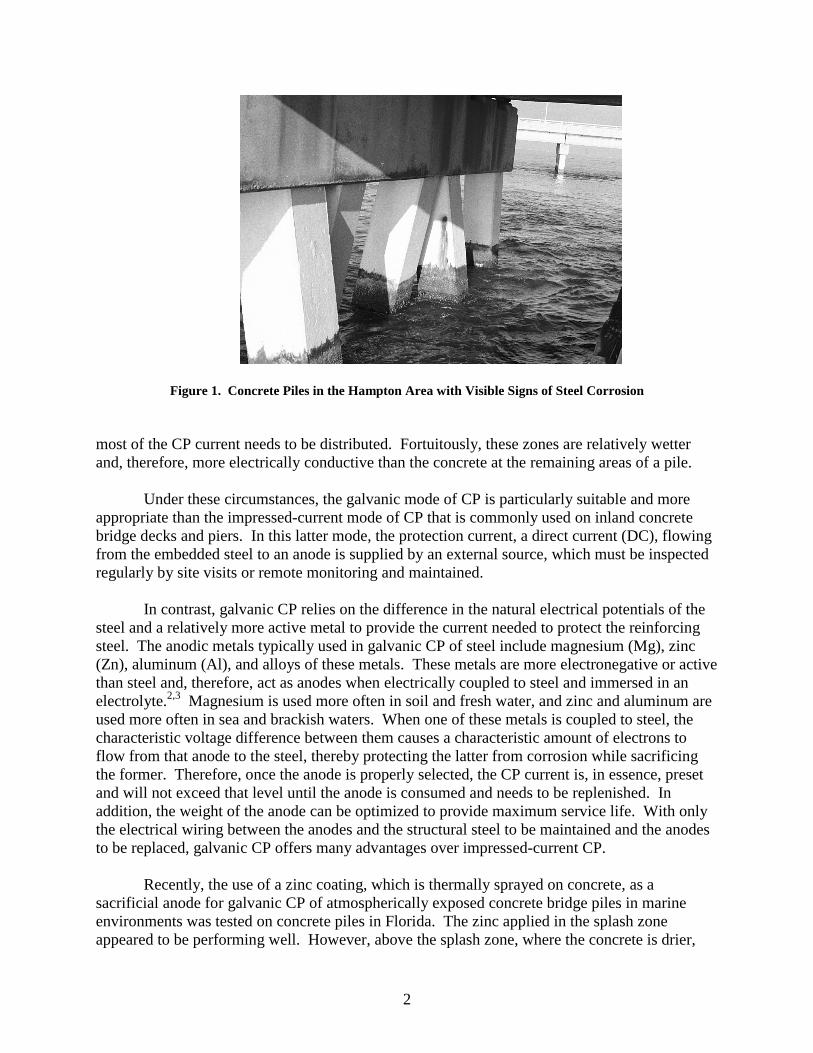
Zinc/Hydrogel Anode The zinc-hydrogel anode material was applied to piles 1-4, 1-5, and 2-2 on concrete at the splash zone and above. This anode consisted of a zinc foil, which measured 0.25 mm (0.010 in) thick by 0.25 m (10 in) wide by 33 m (30 yd) long, a conductive adhesive gel (3M Company’s Hydrogel™) bonded to one side of the foil, and a release paper sticking to the other side of the adhesive gel.6 As Figure 7 shows, the anode was applied to the prepared and dry surface of a concrete pile by first peeling off the release paper (in a portion at a time) and then pressing the bare adhesive hydrogel against the concrete and firmly smoothing the strip until the hydrogel was in firm contact with the concrete surface.
10
Figure 7. Installation of Zn/Hydrogel Anode, Starting From Top of Concrete Pile
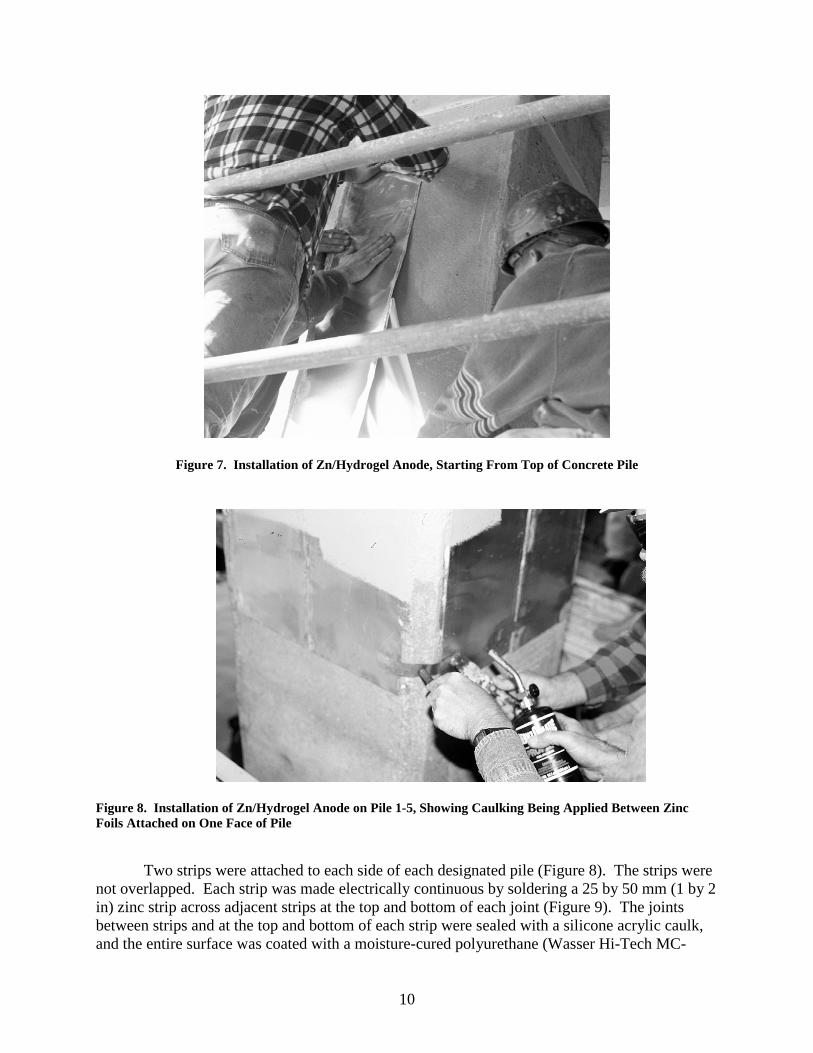
Figure 8. Installation of Zn/Hydrogel Anode on Pile 1-5, Showing Caulking Being Applied Between Zinc Foils Attached on One Face of Pile
Two strips were attached to each side of each designated pile (Figure 8). The strips were
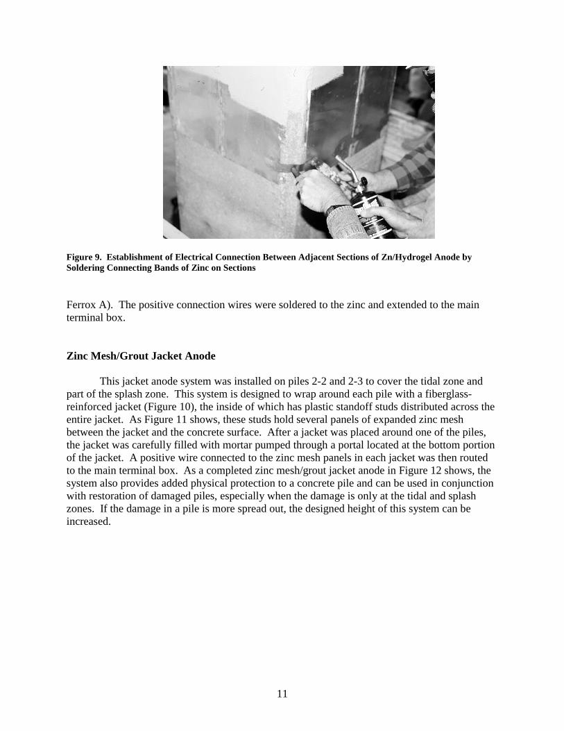
not overlapped. Each strip was made electrically continuous by soldering a 25 by 50 mm (1 by 2 in) zinc strip across adjacent strips at the top and bottom of each joint (Figure 9). The joints between strips and at the top and bottom of each strip were sealed with a silicone acrylic caulk, and the entire surface was coated with a moisture-cured polyurethane (Wasser Hi-Tech MC-
11
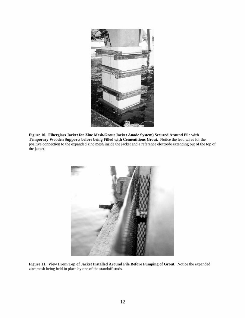
Figure 9. Establishment of Electrical Connection Between Adjacent Sections of Zn/Hydrogel Anode by Soldering Connecting Bands of Zinc on Sections Ferrox A). The positive connection wires were soldered to the zinc and extended to the main terminal box. Zinc Mesh/Grout Jacket Anode This jacket anode system was installed on piles 2-2 and 2-3 to cover the tidal zone and part of the splash zone. This system is designed to wrap around each pile with a fiberglass-reinforced jacket (Figure 10), the inside of which has plastic standoff studs distributed across the entire jacket. As Figure 11 shows, these studs hold several panels of expanded zinc mesh between the jacket and the concrete surface. After a jacket was placed around one of the piles, the jacket was carefully filled with mortar pumped through a portal located at the bottom portion of the jacket. A positive wire connected to the zinc mesh panels in each jacket was then routed to the main terminal box. As a completed zinc mesh/grout jacket anode in Figure 12 shows, the system also provides added physical protection to a concrete pile and can be used in conjunction with restoration of damaged piles, especially when the damage is only at the tidal and splash zones. If the damage in a pile is more spread out, the designed height of this system can be increased.
12
Figure 10. Fiberglass Jacket for Zinc Mesh/Grout Jacket Anode System) Secured Around Pile with Temporary Wooden Supports before being Filled with Cementitious Grout. Notice the lead wires for the positive connection to the expanded zinc mesh inside the jacket and a reference electrode extending out of the top of the jacket.
Figure 11. View From Top of Jacket Installed Around Pile Before Pumping of Grout. Notice the expanded zinc mesh being held in place by one of the standoff studs.

13
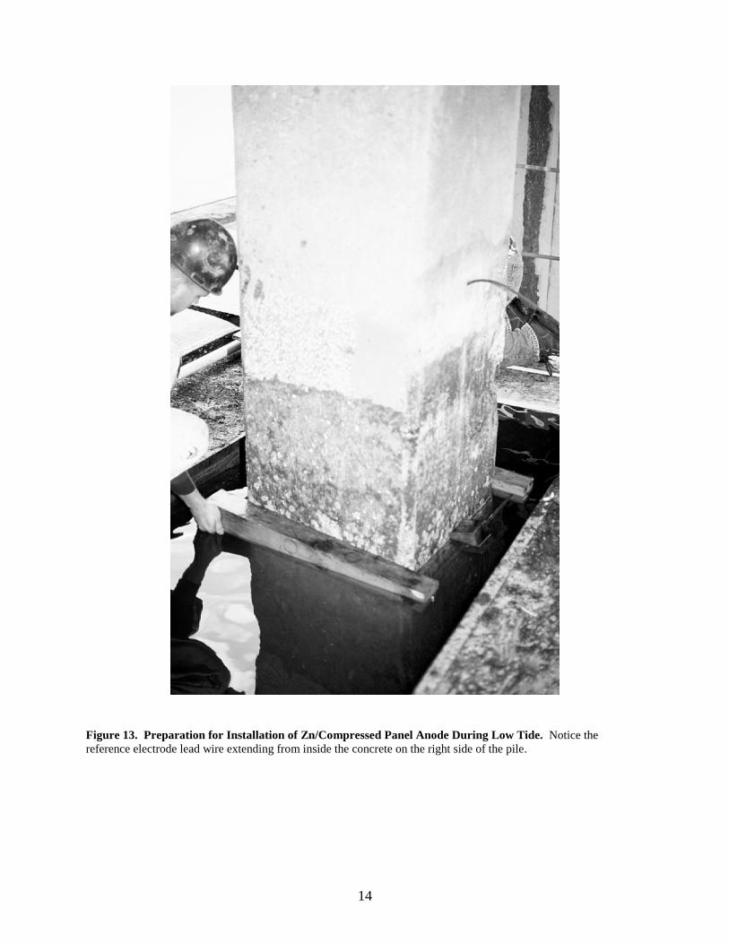
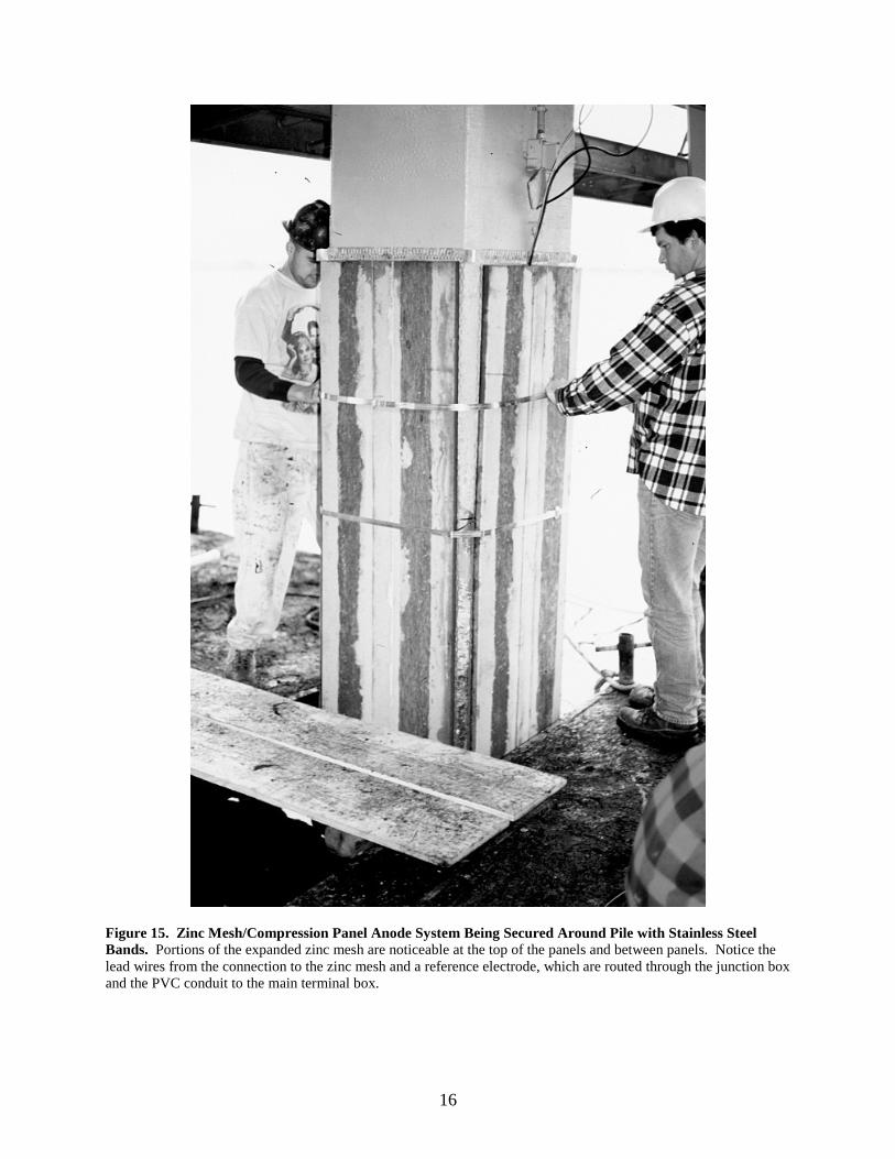
Figure 12. Completed Zn/Grout Jacket Anode. Notice that the grout was beveled at the top and that the filling portal at the bottom of the jacket is visible during low tide. Zinc Mesh/Compressed Panel Anode This anode covered the concrete at the tidal zone and part of the splash zone. The anode consists essentially of several panels of expanded zinc mesh, several stainless steel compression bands, and four formed non-metallic panels—one panel for each face of a pier.8 Each panel was prefabricated from recycled plastic and paper products and formed so that its cross section resembled a chord, with a flat surface and a curved surface. The flat surface has numerous grooves so that when it presses the zinc mesh against the concrete surface of a pile, the grooves permit water to flow between the mesh and concrete face of the pile. The back surface of each panel was curved in such a manner that the stainless steel bands can easily be pulled very tight to press all four panels and the expanded zinc mesh behind them firmly against the concrete pile. As with the other anodes, a positive wire from each mesh panel was routed to the main terminal box. Figures 13 to 15 show the installation of a zinc mesh/compressed panel system.
14
Figure 13. Preparation for Installation of Zn/Compressed Panel Anode During Low Tide. Notice the reference electrode lead wire extending from inside the concrete on the right side of the pile.

15
Figure 14. Workers Securing Four Panels of Expanded Zinc Mesh Around Pile for Zn/Compressed Panel Anode. Notice the long strip of zinc that connects all the panels at the top.
16
Figure 15. Zinc Mesh/Compression Panel Anode System Being Secured Around Pile with Stainless Steel Bands. Portions of the expanded zinc mesh are noticeable at the top of the panels and between panels. Notice the lead wires from the connection to the zinc mesh and a reference electrode, which are routed through the junction box and the PVC conduit to the main terminal box.

17
Observation of the Performance of the Anodes On October 28, 1997, all anode systems were activated simply by connecting the positive wire of each system to its corresponding negative or ground wire with a 0.10 Ω shunt connected between these wires. Immediately after the connection, the current output of each anode on each pile was indirectly measured by measuring the voltage drop across the shunt. This measurement was repeated during every visit to the installation. The responses of the steel to the polarizing current, as indicated by the potential of the steel (with respect to the Ag/AgCl reference electrodes embedded in the piles at various elevations) were also measured during the visits.
During some visits, a depolarization (polarization decay) test was also performed on the steel at different elevations of the piles where reference electrodes were embedded to determine whether the steel was being adequately protected from corrosion. In this widely used test, the current is interrupted (by disconnecting an anode from the steel) and the instant-off potential of the steel is measured; then, the potential is monitored or measured again, typically after 4 hours. The change in the potential during this period of interruption is referred to as the 4-hour polarization decay. The 4-hour period is chosen mainly for convenience, since the decay of polarization often lasted longer than that period. In this investigation, the polarization decay was conducted for approximately 24 hours, so that the tide level during the measurement of the instant-off potential and the last potential would be the same. This was to avoid any potential complication from the effect of changing tide on the potentials. All types of measurements were made with a six-digit 10-MΩ multimeter. During the first 14 months of operation, numerous visits to the test installation were made to inspect the installation and to make these various measurements.
Unfortunately, during the first 21 to 23 days of operation, the installation was vandalized.
The lower electrical junction boxes and conduits on piles 1-2 to 1-5 were ripped off, which severed the connecting wires to the reference electrodes embedded at the lower portions of these four piles. This meant that the potentials for these reference electrodes could not be measured conveniently by connecting the meter between the appropriate terminals at the main junction box. Fortunately, there was enough lead wire left extending out of the concrete for each electrode of these four electrodes so that temporary connection can be manually made to the wire during each measurement of steel potential and potential decay.
RESULTS AND DISCUSSION
Current Outputs of Various Anodes The effectiveness of an anode in providing galvanic CP to the reinforcing steel tendons depends on the amount of current it supplies to the steel. Therefore, the assessment of the effectiveness of the various anodes included measuring the current flowing between each anode and the steel in the piles. As Table 2 shows, there were significant differences between the current outputs of the various anodes. Expressed in current density, i.e., in terms of per unit concrete area underneath each anode, the Zn/compressed panel had the highest average current

18
Table 2. Current Outputs of Various Anodes (mA/m2)
Pile Anode 10/29/97 11/03/97 11/24/97 01/06/98 06/09/98 07/07/98 07/08/98 07/09/98 11/05/98 11/12/98 12/21/98 Mean SD 1-2 Al-Zn-In 12.4 12.0 6.7 5.5 2.2 5.3 9.2 11.0 0.6 4.3 17.8 7.9 64% 1-3 Al-Zn-In 13.8 16.1 6.7 4.8 2.4 6.2 10.2 12.3 0.7 3.8 15.3 8.4 64% 2-1 Al-Zn-In 4.0 3.4 4.5 0.5 1.2 1.9 3.2 0.2 1.9 7.0 2.8 74% 2-5 Al-Zn-In 3.5 3.4 6.7 0.7 0.4 1.2 1.2 2.1 0.1 1.0 1.9 2.0 95% 2-6 Al-Zn-In 8.0 9.8 4.5 1.5 1.1 2.4 5.5 4.9 0.4 2.5 4.9 4.1 71%
Mean 8.4 8.9 5.8 3.1 1.3 3.3 5.6 6.7 0.4 2.7 9.4 5.0 1-4 Zn/Hydrogel 31.7 38.3 30.3 30.0 36.2 44.4 38.9 48.3 15.7 29.0 13.3 32.4 33% 1-5 Zn/Hydrogel 46.5 51.0 43.7 22.0 24.2 26.0 24.3 31.4 13.2 24.8 10.4 28.9 46% 2-2 Zn/Hydrogel 30.5 43.7 35.9 34.7 51.1 42.5 39.3 68.1 14.0 31.7 15.9 37.0 41%
Mean 36.2 44.3 36.6 28.9 37.2 37.6 34.2 49.3 14.3 28.5 13.2 32.8 2-2 Zn/Grout Jacket 52.7 35.9 26.9 24.2 12.1 112.1 98.6 132.1 35.9 45.4 106.3 62.0 68% 2-3 Zn/Grout Jacket 67.3 38.8 29.1 77.6 42.1 60.1 56.7 94.1 45.3 75.5 40.9 57.0 35% 2-4 Zn/Comp. Panel 313.8 179.3 152.4 32.9 29.1 9.4 8.3 15.5 4.6 9.1 5.7 69.1 147% 2-5 Zn/Comp. Panel 313.8 210.7 156.9 42.2 33.6 116.6 103.6 140.1 41.7 64.9 109.7 121.3 69%
Mean 313.8 195.0 154.7 37.6 31.4 63.0 55.9 77.8 23.1 37.0 57.7 95.2 2-1 Bulk Zn 1.18 A 0.87 A 0.62 A 0.61 A 0.34 A 0.40 A 0.37 A 0.51 A 0.30 A 0.51 A 0.31A 0.55 A 48%
Tide Level mid mid high high low high high high low low mid
19
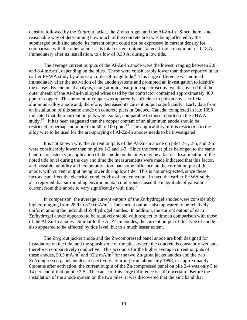
density, followed by the Zn/grout jacket, the Zn/hydrogel, and the Al-Zn-In. Since there is no reasonable way of determining how much of the concrete area was being affected by the submerged bulk zinc anode, its current output could not be expressed in current density for comparison with the other anodes. Its total current outputs ranged from a maximum of 1.18 A, immediately after its installation, to a low of 0.30 A, during a low tide. The average current outputs of the Al-Zn-In anode were the lowest, ranging between 2.0 and 8.4 mA/m2, depending on the piles. These were considerably lower than those reported in an earlier FHWA study by almost an order of magnitude.5 This large difference was noticed immediately after the activation of the anode systems and prompted an investigation to identify the cause. By chemical analysis, using atomic absorption spectroscopy, we discovered that the outer sheath of the Al-Zn-In alloyed wires used by the contractor contained approximately 400 ppm of copper. This amount of copper was apparently sufficient to poison any sacrificial aluminum-alloy anode and, therefore, decreased its current output significantly. Early data from an installation of this same anode on concrete piers in Quebec, Canada, completed in late 1998 indicated that their current outputs were, so far, comparable to those reported in the FHWA study.10 It has been suggested that the copper content of an aluminum anode should be restricted to perhaps no more than 50 to 100 ppm.11 The applicability of this restriction to the alloy wire to be used for the arc-spraying of Al-Zn-In anodes needs to be investigated.
It is not known why the current outputs of the Al-Zn-In anode on piles 2-1, 2-5, and 2-6 were considerably lower than on piles 1-2 and 1-3. Since the former piles belonged to the same bent, inconsistency in application of the anode on the piles may be a factor. Examination of the noted tide level during the day and time the measurements were made indicated that this factor, and possible humidity and temperature, too, had some influence on the current output of this anode, with current output being lower during low tide. This is not unexpected, since these factors can affect the electrical conductivity of any concrete. In fact, the earlier FHWA study also reported that surrounding environmental conditions caused the magnitude of galvanic current from this anode to vary significantly with time.9
In comparison, the average current outputs of the Zn/hydrogel anodes were considerably higher, ranging from 28.9 to 37.0 mA/m2. The current outputs also appeared to be relatively uniform among the individual Zn/hydrogel anodes. In addition, the current output of each Zn/hydrogel anode appeared to be relatively stable with respect to time in comparison with those of the Al-Zn-In anodes. Similar to the Al-Zn-In anodes, the current output of this type of anode also appeared to be affected by tide level, but to a much lesser extent.
The Zn/grout jacket anode and the Zn/compressed panel anode are both designed for
installation on the tidal and the splash zone of the piles, where the concrete is constantly wet and, therefore, comparatively conductive. This accounts for the higher average current outputs of these anodes, 59.5 mA/m2 and 95.2 mA/m2 for the two Zn/grout jacket anodes and the two Zn/compressed panel anodes, respectively. Starting from about July 1998, or approximately 8months after activation, the current output of the Zn/compressed panel on pile 2-4 was only 5 to 14 percent of that on pile 2-5. The cause of this large difference is still uncertain. Before the installation of the anode system on the two piles, it was discovered that the zinc band that

20
electrically links the four expanded zinc mesh panels at the top of one of these Zn/compressed panel systems had broken and was then repaired by solder. The repair may have become undone after the panel system was installed on either pile 2-4 or 2-5. Unfortunately, on which pile the panel system was installed was not noted at the time. Figures 16 to 20 illustrate the fluctuations in the average current outputs of the five anodes during the first 14 months of operation. It is clear that the current outputs of the
Figure 16. Current Outputs of Al-Zn-In Anode on Different Concrete Piles
Figure 17. Current Outputs of Zn-Hydrogel Anode on Three Piles
Zn/compressed panel and the bulk Zn anodes had decreased considerably within the first 30 to 60 days of operation. Of the three anodes used in the tidal and the splash zones, these two have
one commonality: their active element, the zinc, is the most exposed to the seawater. In the case of the bulk zinc anode, it was constantly submerged, whereas in the case of Zn/compressed panel, the exposed portion of the expanded zinc mesh comes into contact with the seawater

21
Figure 18. Current Outputs of Zn-Grout Jacket Anode System on Two Piles
Figure 19. Current Outputs of Zn-Compressed Panel Anode System on Two Piles
Figure 20. Current Output of Submerged Bulk Zn Anode on Pile 2-1

22
during high tide. When the zinc comes into contact with the seawater, it can discharge a high amount of current, much to the seawater, until sufficient oxide is built up over its exposed surface to hinder current flow in that area. This may explain the large drop in the current outputs of these two anodes in the first 30 to 60 days of operation. It appeared that the current outputs of the Zn/hydrogel anodes showed a similar decreasing trend, although to a lesser extent.
Steel Potential
As previous studies have indicated, as long as the steel potential is kept greater than -900
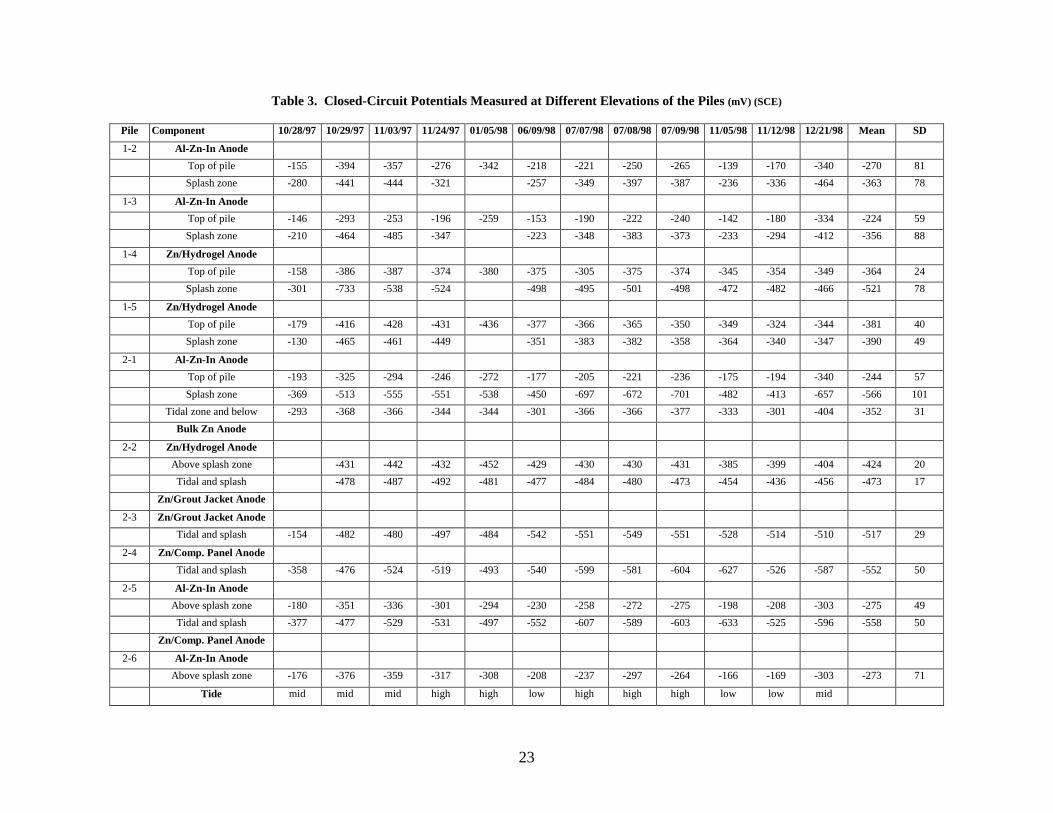
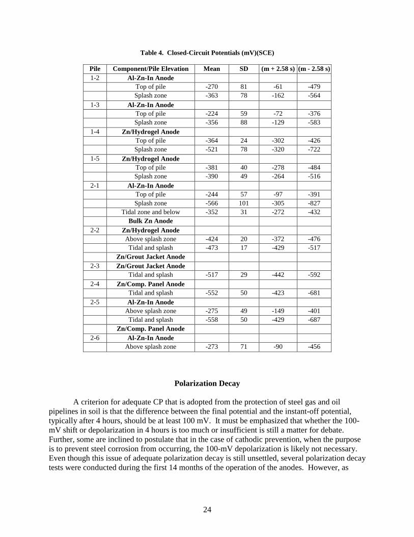
mV (SCE), which is approximately the reversible potential for the formation of atomic hydrogen from the reduction of water molecules, hydrogen embrittlement of the high-strength steel tendons will not occur.1 Table 3 presents the closed-circuit potentials of the steel tendons, as measured by the Ag/AgCl reference electrodes (embedded at different elevations of the piles) and converted to the standard calomel electrode (SCE). The potentials recorded on October 28, 1997, can be considered to approximate the open-circuit potentials of the steel. The potentials for the later dates provide some indication of the extent to which the galvanic currents produced by the different anodes were able to polarize and protect the steel tendons in the concrete. The potential of the steel tendons can vary in accordance with variations in the amount of water and oxygen in the concrete at different elevations of a pile, with moisture in the concrete decreasing with increased elevation or distance from the waterline and oxygen decreasing with decreased elevation. This influence of the amount of oxygen and moisture in the concrete is clearly reflected in the potentials found with the different piles, especially pile 2-1, which was instrumented with reference electrodes at three elevations. The potential was most negative at the splash zone, then at the tidal zone and below, and then at the top of the pile. This suggests that hydrogen embrittlement is more likely to occur at the splash zone than anywhere else in the pile, if at all. A statistical analysis of the potentials, as presented in Table 4, indicated that the most negative potential that could occur, at a 99 percent confidence level, is -827 mV at the splash zone of pile 2-1. This is greater than the -900 mV threshold, which means that even here hydrogen embrittlement is not likely to occur. The steel tendons at this zone of this pile were likely being polarized by current contributed by both the underwater bulk zinc anode and the sprayed Al-Zn-In anode applied on the top portion of the pile. The second most negative potential possible (-722 mV) is at the splash zone of pile 1-4, which was being polarized by current from the Zn/hydrogel anode only. Comparison with the neighboring pile 1-5, which also had a Zn/hydrogel anode, would indicate that the initial potential (measured on October 28, 1997, immediately after the installation of the systems) of a pile influenced the later potentials of a pile. Specifically, despite being polarized by comparable amounts of current from the same type of anodes, the initial and the mean potentials of pile 1-4 were significantly more negative than those of neighboring pile 1-5. Perhaps this suggests that the initial electrochemical status of the steel in a pile, i.e., before the application of any anode, may serve as an indicator for which pile should be closely monitored for hydrogen embrittlement. Based on the analysis in Table 4, it is valid to conclude that, at a 99 percent confidence level, none of the anodes tested would overpolarize the steel tendons to cause hydrogen embrittlement, at least not in the piles tested.
23
Table 3. Closed-Circuit Potentials Measured at Different Elevations of the Piles (mV) (SCE)
Pile Component 10/28/97 10/29/97 11/03/97 11/24/97 01/05/98 06/09/98 07/07/98 07/08/98 07/09/98 11/05/98 11/12/98 12/21/98 Mean SD
1-2 Al-Zn-In Anode Top of pile -155 -394 -357 -276 -342 -218 -221 -250 -265 -139 -170 -340 -270 81 Splash zone -280 -441 -444 -321 -257 -349 -397 -387 -236 -336 -464 -363 78
1-3 Al-Zn-In Anode Top of pile -146 -293 -253 -196 -259 -153 -190 -222 -240 -142 -180 -334 -224 59 Splash zone -210 -464 -485 -347 -223 -348 -383 -373 -233 -294 -412 -356 88
1-4 Zn/Hydrogel Anode Top of pile -158 -386 -387 -374 -380 -375 -305 -375 -374 -345 -354 -349 -364 24 Splash zone -301 -733 -538 -524 -498 -495 -501 -498 -472 -482 -466 -521 78
1-5 Zn/Hydrogel Anode Top of pile -179 -416 -428 -431 -436 -377 -366 -365 -350 -349 -324 -344 -381 40 Splash zone -130 -465 -461 -449 -351 -383 -382 -358 -364 -340 -347 -390 49
2-1 Al-Zn-In Anode Top of pile -193 -325 -294 -246 -272 -177 -205 -221 -236 -175 -194 -340 -244 57 Splash zone -369 -513 -555 -551 -538 -450 -697 -672 -701 -482 -413 -657 -566 101 Tidal zone and below -293 -368 -366 -344 -344 -301 -366 -366 -377 -333 -301 -404 -352 31 Bulk Zn Anode
2-2 Zn/Hydrogel Anode Above splash zone -431 -442 -432 -452 -429 -430 -430 -431 -385 -399 -404 -424 20 Tidal and splash -478 -487 -492 -481 -477 -484 -480 -473 -454 -436 -456 -473 17 Zn/Grout Jacket Anode
2-3 Zn/Grout Jacket Anode Tidal and splash -154 -482 -480 -497 -484 -542 -551 -549 -551 -528 -514 -510 -517 29
2-4 Zn/Comp. Panel Anode Tidal and splash -358 -476 -524 -519 -493 -540 -599 -581 -604 -627 -526 -587 -552 50
2-5 Al-Zn-In Anode Above splash zone -180 -351 -336 -301 -294 -230 -258 -272 -275 -198 -208 -303 -275 49 Tidal and splash -377 -477 -529 -531 -497 -552 -607 -589 -603 -633 -525 -596 -558 50 Zn/Comp. Panel Anode
2-6 Al-Zn-In Anode Above splash zone -176 -376 -359 -317 -308 -208 -237 -297 -264 -166 -169 -303 -273 71
Tide mid mid mid high high low high high high low low mid
24
Table 4. Closed-Circuit Potentials (mV)(SCE)
Pile Component/Pile Elevation Mean SD (m + 2.58 s) (m - 2.58 s) 1-2 Al-Zn-In Anode
Top of pile -270 81 -61 -479 Splash zone -363 78 -162 -564
1-3 Al-Zn-In Anode Top of pile -224 59 -72 -376 Splash zone -356 88 -129 -583
1-4 Zn/Hydrogel Anode Top of pile -364 24 -302 -426 Splash zone -521 78 -320 -722
1-5 Zn/Hydrogel Anode Top of pile -381 40 -278 -484 Splash zone -390 49 -264 -516
2-1 Al-Zn-In Anode Top of pile -244 57 -97 -391 Splash zone -566 101 -305 -827 Tidal zone and below -352 31 -272 -432 Bulk Zn Anode
2-2 Zn/Hydrogel Anode Above splash zone -424 20 -372 -476 Tidal and splash -473 17 -429 -517 Zn/Grout Jacket Anode
2-3 Zn/Grout Jacket Anode Tidal and splash -517 29 -442 -592
2-4 Zn/Comp. Panel Anode Tidal and splash -552 50 -423 -681
2-5 Al-Zn-In Anode Above splash zone -275 49 -149 -401 Tidal and splash -558 50 -429 -687 Zn/Comp. Panel Anode
2-6 Al-Zn-In Anode Above splash zone -273 71 -90 -456
Polarization Decay
A criterion for adequate CP that is adopted from the protection of steel gas and oil pipelines in soil is that the difference between the final potential and the instant-off potential, typically after 4 hours, should be at least 100 mV. It must be emphasized that whether the 100-mV shift or depolarization in 4 hours is too much or insufficient is still a matter for debate. Further, some are inclined to postulate that in the case of cathodic prevention, when the purpose is to prevent steel corrosion from occurring, the 100-mV depolarization is likely not necessary. Even though this issue of adequate polarization decay is still unsettled, several polarization decay tests were conducted during the first 14 months of the operation of the anodes. However, as
25
Table 5. Summary of Polarization Decay
Polarization Decay (mV) Anode System
Pile Elevation Mean SD
Top of pile 103 45 Al-Zn-In Splash zone 169 80 Top of pile 191 49 Zn/Hydrogel Splash zone 235 56
Zn/Grout Jacket Tidal and splash zones 88 31 Zn/Comp. Panel Tidal and splash zones 133 66
Tidal zone 63 24 Bulk Zn Splash zone 123 60
indicated earlier, to eliminate the effect of the changing tide on the potential, the final potentials were measured after approximately 24 hours, instead of just 4 hours.
Table 5 presents a summary of the extent of polarization decay at different elevations on
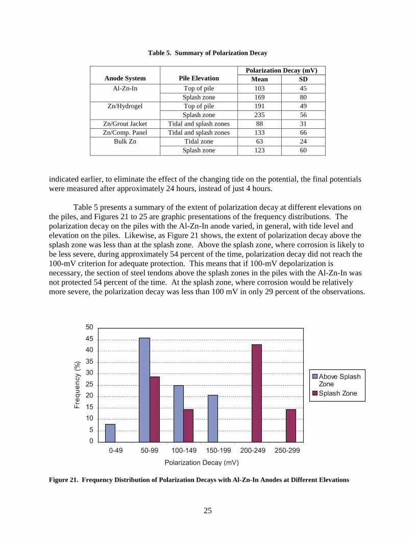
the piles, and Figures 21 to 25 are graphic presentations of the frequency distributions. The polarization decay on the piles with the Al-Zn-In anode varied, in general, with tide level and elevation on the piles. Likewise, as Figure 21 shows, the extent of polarization decay above the splash zone was less than at the splash zone. Above the splash zone, where corrosion is likely to be less severe, during approximately 54 percent of the time, polarization decay did not reach the 100-mV criterion for adequate protection. This means that if 100-mV depolarization is necessary, the section of steel tendons above the splash zones in the piles with the Al-Zn-In was not protected 54 percent of the time. At the splash zone, where corrosion would be relatively more severe, the polarization decay was less than 100 mV in only 29 percent of the observations.
Figure 21. Frequency Distribution of Polarization Decays with Al-Zn-In Anodes at Different Elevations

26
Figure 22. Frequency Distribution of Polarization Decays with Zn/Hydrogel Anodes at Different Elevations
Figure 23. Frequency Distribution of Polarization Decays with Zn-Grout Jacket Anodes at Tidal and Splash Zones
27
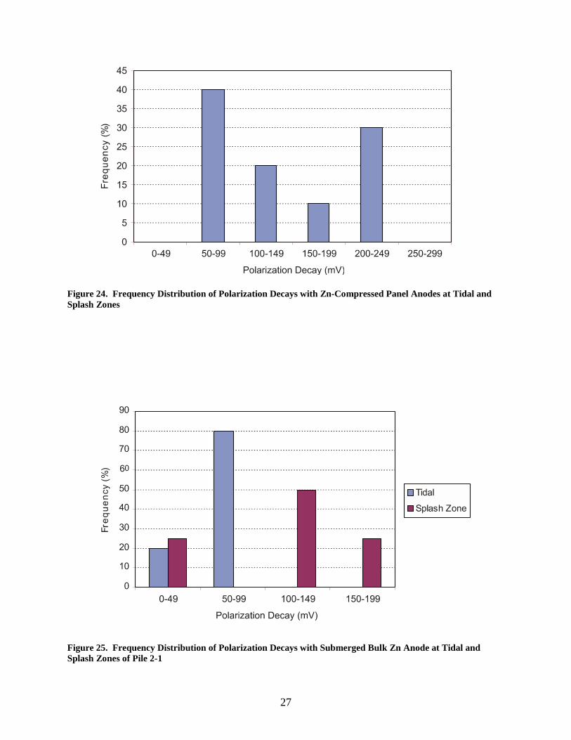
Figure 24. Frequency Distribution of Polarization Decays with Zn-Compressed Panel Anodes at Tidal and Splash Zones
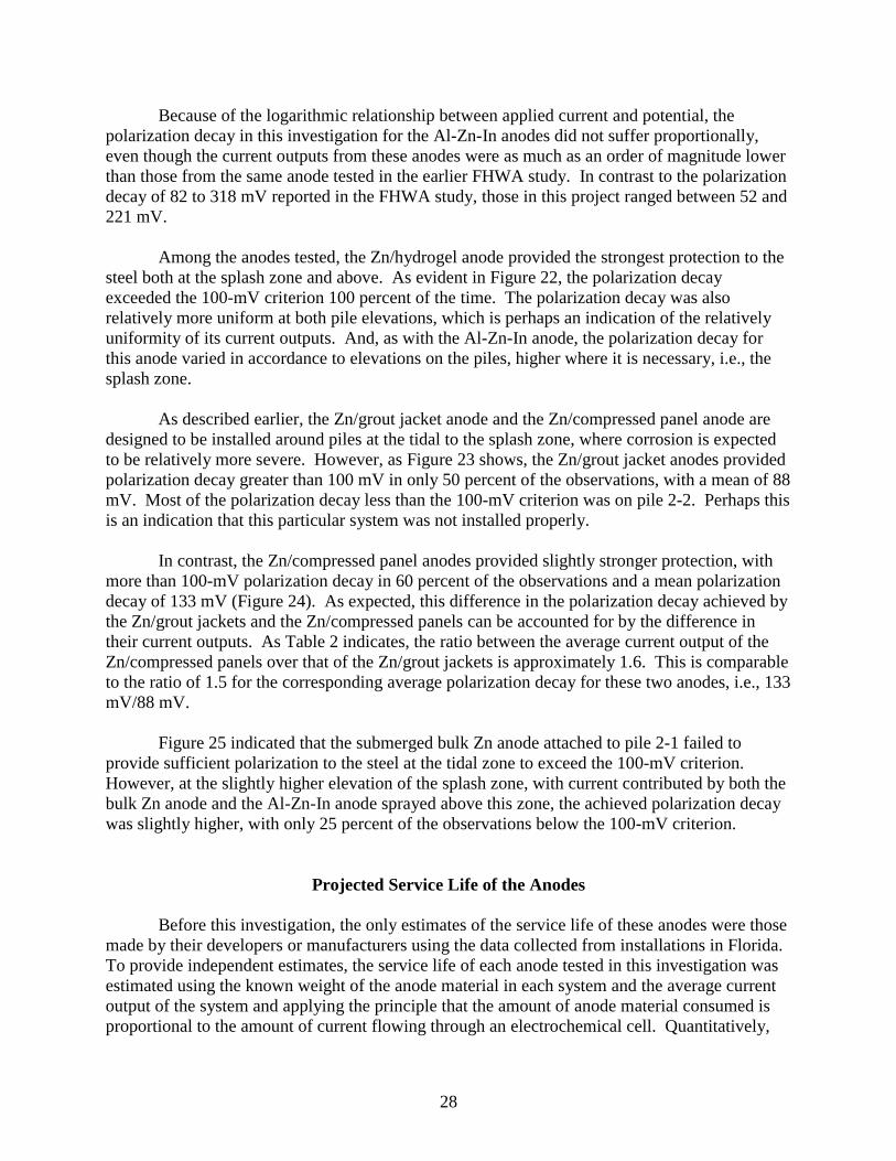
Figure 25. Frequency Distribution of Polarization Decays with Submerged Bulk Zn Anode at Tidal and Splash Zones of Pile 2-1
28
Because of the logarithmic relationship between applied current and potential, the polarization decay in this investigation for the Al-Zn-In anodes did not suffer proportionally, even though the current outputs from these anodes were as much as an order of magnitude lower than those from the same anode tested in the earlier FHWA study. In contrast to the polarization decay of 82 to 318 mV reported in the FHWA study, those in this project ranged between 52 and 221 mV. Among the anodes tested, the Zn/hydrogel anode provided the strongest protection to the steel both at the splash zone and above. As evident in Figure 22, the polarization decay exceeded the 100-mV criterion 100 percent of the time. The polarization decay was also relatively more uniform at both pile elevations, which is perhaps an indication of the relatively uniformity of its current outputs. And, as with the Al-Zn-In anode, the polarization decay for this anode varied in accordance to elevations on the piles, higher where it is necessary, i.e., the splash zone. As described earlier, the Zn/grout jacket anode and the Zn/compressed panel anode are designed to be installed around piles at the tidal to the splash zone, where corrosion is expected to be relatively more severe. However, as Figure 23 shows, the Zn/grout jacket anodes provided polarization decay greater than 100 mV in only 50 percent of the observations, with a mean of 88 mV. Most of the polarization decay less than the 100-mV criterion was on pile 2-2. Perhaps this is an indication that this particular system was not installed properly.
In contrast, the Zn/compressed panel anodes provided slightly stronger protection, with more than 100-mV polarization decay in 60 percent of the observations and a mean polarization decay of 133 mV (Figure 24). As expected, this difference in the polarization decay achieved by the Zn/grout jackets and the Zn/compressed panels can be accounted for by the difference in their current outputs. As Table 2 indicates, the ratio between the average current output of the Zn/compressed panels over that of the Zn/grout jackets is approximately 1.6. This is comparable to the ratio of 1.5 for the corresponding average polarization decay for these two anodes, i.e., 133 mV/88 mV. Figure 25 indicated that the submerged bulk Zn anode attached to pile 2-1 failed to provide sufficient polarization to the steel at the tidal zone to exceed the 100-mV criterion. However, at the slightly higher elevation of the splash zone, with current contributed by both the bulk Zn anode and the Al-Zn-In anode sprayed above this zone, the achieved polarization decay was slightly higher, with only 25 percent of the observations below the 100-mV criterion.
Projected Service Life of the Anodes Before this investigation, the only estimates of the service life of these anodes were those made by their developers or manufacturers using the data collected from installations in Florida. To provide independent estimates, the service life of each anode tested in this investigation was estimated using the known weight of the anode material in each system and the average current output of the system and applying the principle that the amount of anode material consumed is proportional to the amount of current flowing through an electrochemical cell. Quantitatively,

29
according to Faraday’s law, one gram-equivalent-weight of matter is chemically altered at each electrode for one faraday, or 96,501 coulombs, of electricity passing through the electrolyte: W kIt= where W is the weight of the metal reacting or being consumed, k is a constant called the electrochemical equivalent for the anode, t is time in seconds, and I is the current in amperes. For this application, this relationship can be rearranged as follow:
t cWkI
=
where W is the total weight of the anode in each system in gram or gram/square meters, I is the average current flowing through each system (i.e., between the anode and the steel) in amperes or amperes/square meters, t is the average life of the anode system in years, and c is a conversion factor (3.17 x 10⁻⁸). Table 6 presents the estimated average life of these anodes.
Table 6. Estimation of Anode Service Life
Factor Al-Zn-In Zn/Hydrogel Zn/Grout Jacket Zn/Comp. Panel Bulk Zn Equivalent weight (g) 10.519 32.685 32.685 32.685 32.685
K (g/coulomb) 1.09 x 10⁻⁴ 3.39 x 10⁻⁴ 3.39 x 10⁻⁴ 3.39 x 10⁻⁴ 3.39 x 10⁻⁴
Anode weight (g/m2 or g) 0.989 x 10³ 1.792 x 10³ 7.819 x 10³ 7.086 x 10³ 22.70 x 10³
Average current (A/m2 or A) 5.0 x 10⁻³ 32.8 x 10⁻³ 59.5 x 10⁻³ 95.2 x 10⁻³ 0.55 Average life (yr) 59* 5 13 7 4
*See discussion on estimates of service life.
An ideal anode should have the capacity to produce sufficient current to protect the steel and yet have a consumption rate just slow enough to yield a reasonably long service life or economically attractive life-cycle cost. However, as mentioned earlier, a high-current output leads to a high consumption rate and, therefore, a low current output results in a long service life. Consequently, the particular Al-Zn-In anode tested in this investigation, which supplied an unusually small amount of current that was insufficient to polarize the steel, especially at the top portion of the piles, would be projected to last 59 years, which is abnormally longer than the other anodes. Had the Al-Zn-In alloyed wires (used in this test installation) not been contaminated with too much copper, the resulting projected life of this anode would be more consistent with the average of 20 years projected for the earlier test installation.9
The Zn/hydrogel anode, which provided a relatively high amount of current, would last
for an average of only approximately 5 years. However, since this anode was apparently producing more current than necessary, as evidenced by the more than adequate protection to the steel (Figure 22), it is possible to lengthen its life by artificially suppressing the current from this anode. This can be achieved simply by introducing a series resistor into the circuit, which can be sized to effect a certain amount of increase in life. However, it is important to be aware that
30
there is a limit to which the current can be decreased without compromising the protection provided for the steel. Therefore, at most, the life of the Zn/hydrogel anode can be increased by approximately another 5 years by suppressing its current output by 50 percent. Another possible way to lengthen its life is to increase the weight of the zinc used by increasing the thickness of the zinc foil, if the hydrogel can support the added weight. Regarding the two anodes designed for installation around the tidal and splash zones of the piles, the Zn/grout jacket is projected to last longer than the Zn/compressed panel, with an average life of 13 and 7 years, respectively. Unlike the Zn/hydrogel anode, the weight of the zinc used in these systems can be doubled or more to increase the effective life of the systems because of their greater load-carrying capacity. This means that, if desirable, the life of the Zn/grout jacket and the Zn/compressed panel anodes can be doubled or more.
Since the submerged bulk Zn anode produced the largest amount of current, some unknown fraction of which probably dissipated into the surrounding seawater, it is not surprising that it is projected to last for only 4 years, perhaps even less.
All these estimates were based on the assumption that each anode was operating at 100 percent efficiency and will continue to produce current at the levels equivalent to those produced in the first 14 months. The true efficiency is likely to be lower than 100 percent, which would lower the effective life of an anode. This did not include any consideration of possible degradation of materials other than the anode materials themselves (Zn and the Al-Zn-In alloy) that may affect the performance of a particular anode. A case in point is the hydrogel used in the Zn/hydrogel anode system, which is a modified formulation of the conductive hydrogel used for providing good electrode contact with human skin during electrocardiogram examination. This new material is being used in an entirely new application and in a new environment; it has no long-term record yet. It is, therefore, possible that this material may degrade faster than the zinc foil.
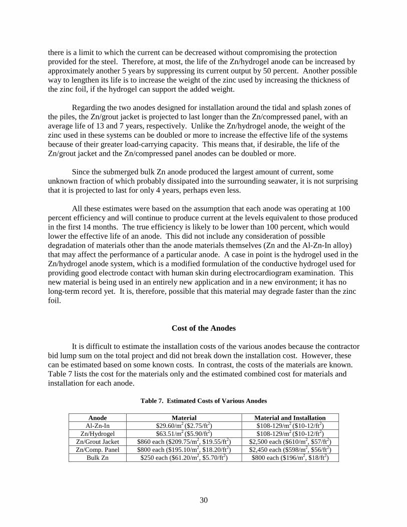
Cost of the Anodes It is difficult to estimate the installation costs of the various anodes because the contractor bid lump sum on the total project and did not break down the installation cost. However, these can be estimated based on some known costs. In contrast, the costs of the materials are known. Table 7 lists the cost for the materials only and the estimated combined cost for materials and installation for each anode.
Table 7. Estimated Costs of Various Anodes
Anode Material Material and Installation Al-Zn-In $29.60/m2 ($2.75/ft2) $108-129/m2 ($10-12/ft2)
Zn/Hydrogel $63.51/m2 ($5.90/ft2) $108-129/m2 ($10-12/ft2) Zn/Grout Jacket $860 each ($209.75/m2, $19.55/ft2) $2,500 each ($610/m2, $57/ft2) Zn/Comp. Panel $800 each ($195.10/m2, $18.20/ft2) $2,450 each ($598/m2, $56/ft2)
Bulk Zn $250 each ($61.20/m2, $5.70/ft2) $800 each ($196/m2, $18/ft2)
31
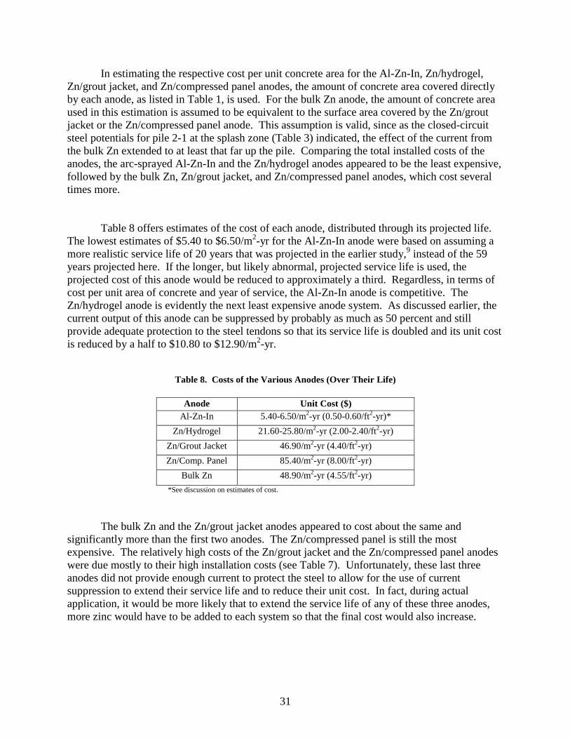
In estimating the respective cost per unit concrete area for the Al-Zn-In, Zn/hydrogel, Zn/grout jacket, and Zn/compressed panel anodes, the amount of concrete area covered directly by each anode, as listed in Table 1, is used. For the bulk Zn anode, the amount of concrete area used in this estimation is assumed to be equivalent to the surface area covered by the Zn/grout jacket or the Zn/compressed panel anode. This assumption is valid, since as the closed-circuit steel potentials for pile 2-1 at the splash zone (Table 3) indicated, the effect of the current from the bulk Zn extended to at least that far up the pile. Comparing the total installed costs of the anodes, the arc-sprayed Al-Zn-In and the Zn/hydrogel anodes appeared to be the least expensive, followed by the bulk Zn, Zn/grout jacket, and Zn/compressed panel anodes, which cost several times more. Table 8 offers estimates of the cost of each anode, distributed through its projected life. The lowest estimates of $5.40 to $6.50/m2-yr for the Al-Zn-In anode were based on assuming a more realistic service life of 20 years that was projected in the earlier study,9 instead of the 59 years projected here. If the longer, but likely abnormal, projected service life is used, the projected cost of this anode would be reduced to approximately a third. Regardless, in terms of cost per unit area of concrete and year of service, the Al-Zn-In anode is competitive. The Zn/hydrogel anode is evidently the next least expensive anode system. As discussed earlier, the current output of this anode can be suppressed by probably as much as 50 percent and still provide adequate protection to the steel tendons so that its service life is doubled and its unit cost is reduced by a half to $10.80 to $12.90/m2-yr.
Table 8. Costs of the Various Anodes (Over Their Life)
Anode Unit Cost ($)
Al-Zn-In 5.40-6.50/m2-yr (0.50-0.60/ft2-yr)* Zn/Hydrogel 21.60-25.80/m2-yr (2.00-2.40/ft2-yr)
Zn/Grout Jacket 46.90/m2-yr (4.40/ft2-yr) Zn/Comp. Panel 85.40/m2-yr (8.00/ft2-yr)
Bulk Zn 48.90/m2-yr (4.55/ft2-yr) *See discussion on estimates of cost.
The bulk Zn and the Zn/grout jacket anodes appeared to cost about the same and significantly more than the first two anodes. The Zn/compressed panel is still the most expensive. The relatively high costs of the Zn/grout jacket and the Zn/compressed panel anodes were due mostly to their high installation costs (see Table 7). Unfortunately, these last three anodes did not provide enough current to protect the steel to allow for the use of current suppression to extend their service life and to reduce their unit cost. In fact, during actual application, it would be more likely that to extend the service life of any of these three anodes, more zinc would have to be added to each system so that the final cost would also increase.

32
CONCLUSIONS • When galvanic CP is applied to the prestressed concrete piles using any of these anodes,
hydrogen embrittlement of the steel tendons is unlikely. This is because it is highly improbable that any of the five anodes tested would polarize the steel tendons in the concrete piles excessively.
• For applying CP at the tidal and splash zones, as a whole, the Zn/grout jacket is a better
anode than the Zn/compressed panel, especially when the concrete in these areas is already damaged. The grout jacket also provides restoration of the piles after removal of loose concrete.
• For applying CP at the splash zone and above, the Al-Zn-In anode is better since the
Zn/hydrogel costs more and will have a significantly shorter service life. In addition, the long-term durability of the hydrogel, which is a critical component in the Zn/hydrogel system, is still unknown. Further, there is a concern with the eventual buildup of a layer of zinc oxide, as a result of the consumption of the zinc, between the zinc foil and the hydrogel. This relatively resistive layer would increase the overall electrical resistance of the circuit, which would, in turn, reduce the effective current output of this anode. An additional advantage of the Al-Zn-In system is that it can be easily applied, if necessary, to the pile caps and the soffits.
• To ensure that the Al-Zn-In anode will produce the current it is capable of producing,
specifications for Al-Zn-In should include a maximum limit of 100 ppm on the copper content of the alloyed wire to be used for arc-spraying of the anode.11
RECOMMENDATIONS • Continue observing the anodes for a few more years. Except for the bulk anode, the anodes
investigated in this study are new and are designed especially for application in galvanic CP of marine concrete piles and piers. Long-term data are needed, especially for determining the durability of new materials such as the conductive hydrogel.
• Consider applying CP to the concrete piles in the Hampton area immediately in accordance
with the conclusions.
ACKNOWLEDGMENTS The authors express their gratitude to the Office of Technology Applications, especially to John M. Hooks, for the funding support, without which this investigation would not be possible. Appreciation is also extended to other colleagues at the Federal Highway Administration, particularly Y. Paul Virmani, of the Turner-Fairbank Highway Research Center, and Claude S. Napier, of the Virginia Division, for their valuable input. We also thank Malcolm

33
T. Kerley, State Bridge Engineer of the Commonwealth of Virginia, and Vince J. Roney, Suffolk District Bridge Engineer, for their valuable cooperation. The assistance provided by the Media Group at VTRC is also appreciated.
REFERENCES 1. Hartt, W. H., and Kumaria, C. C. Influence of Potential, Chloride, pH and Precharging Time
on Embrittlement of Cathodically Polarized Prestressed Steel. Corrosion, Vol. 49, No. 5, pp. 377-385, 1993.
2. LaQue, F. L. Marine Corrosion, Causes and Prevention. John Wiley & Sons, New York,
1975. 3. Brasunas, A., Ed. NACE Basic Corrosion Course, Chapter 3. National Association of
Corrosion Engineers, Houston, 1970. 4. Young, W. T., and Funahashi, M. Improved Anode for Galvanic Cathodic Protection of
Steel in Concrete. NACE International Conference on Corrosion and Infrastructure, Baltimore, November 1995.
5. Funahashi, M., and Young, W.T. Development of a New Sacrificial Cathodic Protection
System for Steel Embedded in Concrete. Report No. FHWA-RD-96-171. Federal Highway Administration, Washington, D.C., May 1997.
6. Bennett, J. E., and Shue, T. J. Galvanic Cathodic Protection of Reinforced Concrete Bridge
Members Using Sacrificial Anodes Attached by Conductive Adhesives. Report No. FHWA-RD-96-073. Federal Highway Administration, Washington, D.C., December 1996.
7. Kessler, R. J., Powers, R. G., and Lasa, I. R. Zinc Mesh Anodes Cast into Concrete Pile
Jackets. NACE Corrosion 96, Denver, 1996. 8. Kessler, R. J., Lasa, I. R., and Powers, R. G. Cathodic Protection Using Scrap and Recycled
Materials. Material Performance, Vol. 30, No. 6, pp. 29-31, June 1991. 9. Funahashi, M., and Young, W. T. Field Evaluation of a New Aluminum Alloy as a
Sacrificial Anode for Steel Embedded in Concrete. Report No. FHWA-RD-98-058. Federal Highway Administration, Washington, D.C., April 1998.
10. Funahashi, M. Personal Communication, February 1999. 11. Smith, S. N., and Goolsby, A. T. Consumer’s Perspective of Aluminum Anode Quality Test
Design. NACE Corrosion 96, Denver, 1996.


![UFGS 33 52 43 Aviation Fuel Distribution (Non-Hydrant) 33 52 43.pdf · cathodic protection system (sacrificial anode)] [section 26 42 13.00 20 cathodic protection by galvanic anodes]](https://static.fdocuments.in/doc/165x107/5ace76057f8b9a56098bd4c5/ufgs-33-52-43-aviation-fuel-distribution-non-hydrant-33-52-43pdfcathodic-protection.jpg)


![Development and testing of galvanic anodes for cathodic protection · 2017. 9. 14. · DNV, RP B401, Appendix A, [14] is mainly intended to serve 332 Joan Genescà and Julio Juárez.](https://static.fdocuments.in/doc/165x107/6114925eb6b0de7a1850f082/development-and-testing-of-galvanic-anodes-for-cathodic-protection-2017-9-14.jpg)


