Final Report -...
54
Final Report Team 2: Dwell Senior Design Project 5/10/18 Kyra Black Cameron Carley Kyle Sutton Nathaniel Veldboom
Transcript of Final Report -...

Final Report
Team 2: Dwell
Senior Design Project
5/10/18
Kyra Black
Cameron Carley
Kyle Sutton
Nathaniel Veldboom

Copyright © 2018, Calvin College, Kyra Black, Cameron Carley, Kyle Sutton, Nathaniel Veldboom

EXECUTIVE SUMMARY
This project will satisfy the capstone requirements of Calvin College's engineering program. The name of
the group is Team 2: Dwell. It is comprised of four Civil & Environmental engineering students: Kyra
Black, Cameron Carley, Kyle Sutton, and Nate Veldboom. This project report further outlines the project
goals, research conducted, design decisions, and final design choices to be used in the shelter prototype
and the base camp layout.
The Shelter Design Competition, hosted by John Brown University and sponsored by Samaritan's Purse,
established the set of guidelines and criteria for which the disaster shelter is designed. The competition's
scenario is in response to the 2015 earthquake in Nepal, which measured a 7.8 magnitude on the Moment
Magnitude Scale. The shelter is designed to be a transitional shelter (lasting 1 to 3 years) for victims of
natural disasters and is not intended to provide permanent residence.
The team's design decisions are based on the requirements set forth by the competition and the
environmental conditions of Nepal. The frame is largely made of 1" Schedule 80 and Schedule 40 PVC.
The shelter cover is constructed using a series of heavy-duty tarps and insulated with double bubble foil
insulation. The shelter has a footprint of 16x10ft (5x3meters) and is roughly 8 feet (2.4 meters) in height.
The shelter accommodates a family of four and is designed to withstand wind speeds of 50 mph (75
km/hour) and earthquake tremors/aftershocks. The shelter kit is required to be easily transported and
constructed with basic tools.
The camp layout is based on requirements set forth by the competition and follows the basic humanitarian
standards established by The Sphere Handbook. The camp layout accommodates 5000 people in 1250
shelters and is designed with an egalitarian view, that everyone should have equal access to resources.
The camp layout is set up in triangular and hexagonal units, each with access to facilities such as water
tanks, showers, toilets, refuse bins, and medical centers.
The disaster relief shelter is efficient. The total cost of the shelter is approximately $1275. Broken down
into components: the material cost is $1135.32, the manufacturing cost is $97.43, and the transportation
cost is approximately $42 per shelter kit. Per a standard 40x8x8.5 ft shipping container, approximately 60
shelters can be shipped at once.

1
TABLE OF CONTENTS EXECUTIVE SUMMARY ........................................................................................................................... i
Table of Figures and Tables .......................................................................................................................... 3
1. Project Management ............................................................................................................................. 4
1.1 Introduction ......................................................................................................................................... 4
1.2 Team Members ................................................................................................................................... 4
Kyra Black ............................................................................................................................................ 4
Cameron Carley .................................................................................................................................... 4
Kyle Sutton ........................................................................................................................................... 4
Nathaniel Veldboom ............................................................................................................................. 4
1.3 Team Organization .............................................................................................................................. 4
1.4 Schedule .............................................................................................................................................. 5
1.5 Budget ................................................................................................................................................. 5
2. Project Overview .................................................................................................................................. 6
2.1 Background ......................................................................................................................................... 6
2.2 Existing Shelters ................................................................................................................................. 7
2.3 Project Requirements .......................................................................................................................... 9
Emergency Design Shelter Prototype Requirements ............................................................................ 9
Base Camp Layout Requirements ....................................................................................................... 10
3. Design Decisions .................................................................................................................................... 11
3.1 Framing ............................................................................................................................................. 11
3.2 Cover ................................................................................................................................................. 12
3.3 Insulation........................................................................................................................................... 13
3.4 Structural Anchor .............................................................................................................................. 14
3.5 Bolt Design ....................................................................................................................................... 15
3.6 Floor Tiles ......................................................................................................................................... 16
3.7 Cross Bracing .................................................................................................................................... 17
4. Prototype Criteria .................................................................................................................................... 18
4.1 Physical Requirements ...................................................................................................................... 18
4.2 Strength requirements and Weather Resistance ................................................................................ 19
4.3 Heat Loss and Ventilation Requirements .......................................................................................... 20
4.4 Life Span Requirements .................................................................................................................... 20
4.5 Assembly Requirements ................................................................................................................... 20
4.6 Packability Requirements ................................................................................................................. 20
4.7 Reusability and Expandability .......................................................................................................... 20
4.8 Cost ................................................................................................................................................... 21

2
4.9 Cultural Appropriateness .................................................................................................................. 22
5. Camp Plan ............................................................................................................................................... 23
5.1 Description ........................................................................................................................................ 23
5.2 Cost Estimate .................................................................................................................................... 28
6. Modifications/ Improvements ................................................................................................................. 28
6.1 Bolted Connections ..................................................................................................................... 28
6.2 Insulation..................................................................................................................................... 29
6.3 Ventilation ................................................................................................................................... 29
6.4 Lighting ....................................................................................................................................... 30
6.5 Durability .................................................................................................................................... 30
7. Christian Perspective .............................................................................................................................. 31
8. Competition Results ................................................................................................................................ 32
9. Conclusion .............................................................................................................................................. 32
Acknowledgements: .................................................................................................................................... 33
References: .................................................................................................................................................. 34
Table of Appendices: .................................................................................................................................. 35
A. Calculations ..................................................................................................................................... 35
B. Camp Plan ....................................................................................................................................... 35
C. Competition Scoring Matrix ........................................................................................................... 35
D. Construction Directions .................................................................................................................. 35
Appendix A1: Wind Calculations ............................................................................................................... 36
Code: ASCE 7-10: 27.3.2 Velocity Pressure: ......................................................................................... 36
Total Loads on Each Wall When Resisting Wind: ................................................................................. 36
Appendix A2: Anchoring Calculations ....................................................................................................... 37
Appendix A3: Bolt Design Calculations ..................................................................................................... 38
Appendix B1: Idealized & Site-Specific Camp Plans................................................................................. 39
Appendix B2: Large Scale B-Unit with Encampment and Storage Areas .................................................. 41
Appendix B3: Camp Plan Component Dimensions .................................................................................... 42
Appendix B4: Encampment & Storage Area Dimensions .......................................................................... 45
Appendix B5: Encampment & Storage Area Spatial Distribution .............................................................. 47
Appendix C: Competition Scoring Matrix .................................................................................................. 48

3
TABLE OF FIGURES AND TABLES
Figure 1: Nepal’s Geographic Location ….................................................................................................. 6
Figure 2: Disaster relief tents in Nepal 1 month after 2015 earthquake …................................................. 7
Figure 3: Bamboo and metal sheet shelter ….............................................................................................. 8
Figure 4: Samaritan’s Purse corrugated iron shelter …............................................................................. 9
Table 1: Decision matrix for frame material …......................................................................................... 11
Figure 5: Aerial view of assembled frame …............................................................................................ 12
Table 2: Decision matrix for insulation material ....................................................................................... 14
Figure 6: Diagram of weighted bags resisting overturning …....................................................................15
Figure 7: Visual representation of bolted 3-way joint ............................................................................... 16
Table 3: Results of Design Calculations for ¼ inch diameter grade 5 steel bolts ..................................... 16
Figure 8: Visual representation of interlocking foam tiles ........................................................................ 17
Figure 9: Visual representation of cross bracing …................................................................................... 18
Table 4: Physical Requirements Summary …........................................................................................... 18
Figure 10: StaadPro model of final design …............................................................................................. 19
Table 5: Breakdown of Material Cost ....................................................................................................... 21
Table 6: Time and cost to drill and cut parts …......................................................................................... 22
Figure 11: Augustus B. Woodward’s Plan of Detroit & Fernando Romero’s Border City …................... 23
Figure 12: Modular units of camp plan …................................................................................................. 24
Figure 13: Idealized Camp Plan ................................................................................................................ 25
Figure 14: SU-30 Design Vehicle ............................................................................................................. 26
Figure 15: Site-specific camp plan variant …............................................................................................ 27
Table 7: Cost Estimate for Camp Plan ….................................................................................................. 28
Figure 16: Metal collar used to guide drill press for drilling joint connections ........................................ 29

4
1. PROJECT MANAGEMENT
1.1 INTRODUCTION
Calvin College is a Christian, liberal arts college in Grand Rapids, Michigan. Calvin has a four-year
ABET-accredited engineering program. Within this program, Senior Design is required of all senior
engineering students to connect the concepts learned in class to a “real-world” problem. The intention of
the senior design project is to transition students into a career as a practicing engineer, but also to offer
support, by means of advisors, to aid in the transition. The project scope included competing in a disaster
relief shelter competition sponsored by John Brown University and Samaritan’s Purse. This competition
included designing and building a shelter prototype and designing a camp plan, to meet the competition
requirements. The team, project, and criteria are outlined in the following report.
1.2 TEAM MEMBERS
KYRA BLACK
Kyra is a Senior Civil/Environmental Engineering Major. She enjoys tutoring Calculus and giving tours
in the Calvin College Ecosystem Preserve. This past summer she interned with RWG Engineering LLC
doing site design. Upon graduation, she hopes to work in site design and land development.
CAMERON CARLEY
Cameron is a Civil/Environmental Engineering major with a Geography minor from Livonia, Michigan.
He enjoys travel, photography, and urbanism. Last summer, he worked as a business intern at Central
Detroit Christian Community Development Corporation in Detroit, Michigan, and has interned at civil
engineering firms in the private and public sectors in the past. After graduation, he plans to attend the
University of Michigan to pursue a Master of Urban and Regional Planning.
KYLE SUTTON
Kyle is a Civil/Environmental Engineering major with a business minor from Aurora, Ohio. This past
summer he interned with Spectrum Health in their Real Estate and Facility Development division as an
architectural planner. Kyle plans on working in engineering or business/finance upon graduating in May
of 2018.
NATHANIEL VELDBOOM
Originally from the small Northern MI town of East Jordan, Nate is on track to graduate from Calvin
College as a Civil/Environmental Engineering major and with a minor in Mathematics in 2018. Nate has
worked several internships ranging from serving as on-site inspector to testing storm outfalls. Nate plans
on pursuing work in some field of civil engineering following graduation.
1.3 TEAM ORGANIZATION
Each of the team members had a specific role to play during the design process. Kyle Sutton and Nate
Veldboom modeled the proposed shelter and performed calculations to select parts needed, helped with
the writing of the report, and built the shelter prototype. Cameron Carley took on the responsibility of

5
designing the camp layout for the competition. He researched all the requirements listed in the Sphere
Handbook and designed the camp plan in AutoCAD. Kyra Black kept the team organized through
overseeing the schedule, budget, parts order forms, and required reports and presentation. Design
decisions were made by the team or by the person who was most experienced in that area of the project. If
disagreement arose, everyone’s perspective was made clear, and each member was expected to decide
based on what was best for the project.
Though the immediate team consists of four students, there are many other supporting members including
the team faculty advisor, Professor De Rooy, and the other senior design professors.
1.4 SCHEDULE
This project was on a tight schedule due to the competition deadlines. A project report was required by
April 2nd, and the final design and shelter required by April 18th. Therefore, the team divided the project
into sections to be completed to meet these deadlines. The first section was research. The team collected
information about Nepalese culture, its weather and terrain, materials that could be used for the shelter,
and necessary camp plan elements. A greater understanding of these components aided the team in
making decisions about the design of the shelter. This phase was finished by the end of January.
The next steps were to design and build. Using the information collected during the research phase, the
team brainstormed design alternatives for the shelter itself. After designing two or three shelter
alternatives, the team chose the best option to build. After the basic design was chosen, the team began to
order parts and build the prototype. After refining the final design, a final prototype was built to bring to
the competition. The design and build phase began at the end of January and was finalized with the final
design that was taken to the competition.
The final stage was presentation. The team brought the shelter to John Brown University on April 18th
for testing and presentation. Presentations were also given for the Engineering Department’s Senior
Design Night, and the American Society of Civil Engineers (ASCE) May luncheon.
1.5 BUDGET
The team’s budget primarily revolved around the constraints placed on the competition by John Brown
University, which helped compensated the team for their final shelter through a stipend of $1000. This
stipend was not effective until after the completion of the competition in April. The competition entrance
fee was $250, and the final shelter was required to cost no more than $1500. The team received the Eric
DeGroot Memorial Fund monies ($1200) to cover the competition entrance fee and the shelter prototype
material cost. Therefore, the team’s goal was to remain within a budget of $1200, not including the
expected stipend.

6
2. PROJECT OVERVIEW
2.1 BACKGROUND
Figure 1. Nepal’s Geographic Location1
The country of Nepal is the target country for this disaster relief shelter. Nepal is landlocked
between China and India (Figure 1). It is a very mountainous country, with a portion of the Himalayan
mountain range enclosed within its borders. Consequently, the country goes from 0 to 9000 meters in
elevation, of which 5000 meters and below are habitable. Nepal also experiences 5 seasons – spring,
summer, monsoon, fall, and winter. Nepal did not become a democratic republic until 2008 after a century
of isolation and conflict. As a result, Nepal is one of the least developed countries in the world.2 In April
2015, a 7.8 magnitude earthquake hit Kathmandu, the capital of Nepal. Thousands of buildings were
reduced to rubble and thousands of people lost their lives. The United Nations estimated that 6.6 million
people were affected by the earthquake in some way3. Samaritan’s Purse, an international relief
organization, began distributing relief items soon after. They also began teaching the local people about
earthquake-resistant construction and how to build their own temporary structures using provided shelter
kits4. As Nepal continues to rebuild, Samaritan’s Purse has sponsored the competition hosted by John
1 “Map of Nepal”. WELNepal. 2011. WELNepal. Web 20 Nov. 2017. <http://www.welnepal.org/homeMap.html>.
2 Proud, Richard, Zuberi, Matinuzzaman. “Nepal”. Encyclopǽdia Britannica. 24 March 2017. Encyclopǽdia
Britannica, Inc. Web. 7 Dec. 2017. <https://www.britannica.com/place/Nepal/The-people>.
3 “Nepal Earthquakes: Devastation in Maps an Images.” BBC News World. 15 May 2015. BBC. Web. 13 Nov.
2017. <http://www.bbc.com/news/world-asia-32479909>.
4 “Sheltering Nepal”. Samaritan’s Purse. 26 Nov. 2015. Samaritan’s Purse. Web. 13 Nov. 2017.
<https://www.samaritanspurse.org/article/sheltering-nepal/>.

7
Brown University to bring awareness to the struggles that face the Nepalese people as well as bring new
solutions to the problems of temporary housing and disaster relief.
2.2 EXISTING SHELTERS
The team researched disaster relief shelters currently used in Nepal to aid in the decision-making process.
Three shelters currently used are a tent, a bamboo and metal sheet construction, and a corrugated iron
shelter kit distributed by Samaritan’s Purse.
First, a tent-like structure was easy to construct after the earthquake struck Nepal in April 2015. Shown
below in Figure 2, the Nepalese people built shelters quickly out of salvaged materials. Tents in general
are easy to construct and portable, making them easy to move in a disaster situation, and are durable and
waterproof. Tents are also affordable: the United Nations High Commissioner for Refugees (UNHCR)
canvas tent design costs approximately $200 to manufacture5. For Nepal specifically, the framing system
must be strong enough to withstand an earthquake. The tent must also retain heat well to keep its
inhabitants warm in higher elevations.
Figure 2. Disaster relief tents in Nepal 1 month after 2015 earthquake.6
Second, the bamboo and metal sheet structure, shown in Figure 3, is currently being used in Nepal. The
materials are affordable as bamboo is readily available in Nepal. The framing would be able to withstand
an earthquake as bamboo is very strong. There are also specific instructions for assembling the shelter,
5 Laylin, Tafline. “10 refugee shelters I love, for the good and the bad”. Green Prophet. 14 March 2014. Green
Prophet. Web. 6 Dec. 2017. <https://www.greenprophet.com/2014/03/pros-and-cons-10-refugee-shelters/>.
6 Sokol, Brian. “Struggling amid the ruins a month after Nepal quake”. Al Jazeera. 25 May 2015. Al Jazeera media
Network. Web 26 March 2018. <https://www.aljazeera.com/indepth/inpictures/2015/05/struggling-ruins-month-
nepal-quake-150525062223409.html>.

8
but it takes 1 to 3 days to construct, which would not be conducive to quick assembly in a disaster
situation7. The continued concern is heat retention and adequate insulation.
Figure 3. Bamboo and metal sheet shelter
Third, Samaritan’s Purse has implemented a shelter kit in Nepal, shown in Figure 4. The kit consists of
corrugated, galvanized iron sheeting, plastic tarpaulin, rope or cord, and other non-food items such as
basic tools, blankets, and cookware. It is easy to construct as well as cost-effective. Samaritan’s Purse,
along with distributing supplies, implemented a program to instruct those receiving the shelters on how to
build it themselves. The shelter is strong and durable8. However, it is unclear whether more insulation
would be needed for temperatures at higher elevations.
7 Frearson, Amy. “Prototype shelter for Nepal earthquake victims could be built by unskilled workers in three days”.
Dezeen. 11 July 2015. Dezeen. Web. 6 Dec. 2017. <https://www.dezeen.com/2015/07/11/prototype-bamboo-shelter-
nepal-earthquake-victims-built-by-unskilled-workers-three-days/>.
8 “Sheltering Nepal”. Samaritan’s Purse. 26 Nov. 2015. Samaritan’s Purse. Web. 6 Dec. 2017.
<https://www.samaritanspurse.org/article/sheltering-nepal/>.

9
Figure 4. Samaritan’s Purse corrugated iron shelter
2.3 PROJECT REQUIREMENTS
The design competition at John Brown University imposed numerous constraints and requirements
concerning the emergency shelter prototype and base camp layout. As the competition was in response to
the 7.8 magnitude (Richter scale) earthquake that struck Nepal in 2015, requirements surrounding the
prototype and base camp layout were tailored for that specific environment and culture.
EMERGENCY DESIGN SHELTER PROTOTYPE REQUIREMENTS
Regarding the emergency shelter, the prototype had to accommodate a family of four with a minimum
allocation of 37.7 ft2 (3.5 m2) of floor space per person. The height within the structure had to allow a
head clearance of 6.6 ft (2 m) for at least 70% of the floor space, and the maximum footprint of the
structure allowed was 16’ x 20’ (5m x 6m). Additionally, the prototype had to demonstrate cultural
appropriateness for use in Nepal, so as not to inhibit any social, cultural, or religious requirements.
The physical performance of the structure was expected to withstand wind loads of 50 mph (75 km/hour)
and seismic earthquake loads similar in magnitude to what struck Nepal (7.8 Moment Magnitude scale) in
2015. The shelter had to be versatile and responsive to the scenario environmental conditions that vary
seasonally, geographically, and diurnally. Furthermore, the structure had to shield occupants from
substantial rainfall (4 inches per hour), promote adequate airflow ventilation in various temperatures, and
retain heat in temperature fluctuations due to day/night and summer/winter variations. It was also
expected that assembly of the structure be straightforward with simple hand tools, be upgradeable to a
more permanent structure, preferably with readily available local materials, and be reusable.
The expected life-span of the structure had to be a minimum of one year, and cost less than $1500 in
materials to construct. The structure’s overall weight had to not exceed 440 lbs. (200 kg), and the design
of the structure had to maximize efficiency of space when shipping and storing numerous structures in 8’
x 40’ shipping containers.

10
BASE CAMP LAYOUT REQUIREMENTS
The base camp layout was mandated to accommodate 5000 people in 1250 shelters. The main
considerations regarding the camp layout were road/walk ways, water and waste requirements, and
arrangement of shelters and support facilities. An estimate for the cost of construction of the camp was
required, and it was assumed that no site preparation costs were necessary.
11
3. DESIGN DECISIONS
3.1 FRAMING
The framing of a structure served two purposes; shape and support. The frame supported the weight of the
building, the internal and external loads applied, and provided a structure to inhabit. The framing also
formed the overall shape of a building, which influenced the use of the space as well as the loads it can
endure. The competition, as previously elaborated, tested external loads such as wind/rain and seismic
loads. The shelter had to withstand an earthquake simulation with no failure and little to no deformation.
Framing materials of the shelter were considered with respect to characteristics such as strength, cost,
weight, and ease of access in the areas the shelter may be employed. Material strength was given the
highest priority, so the structure would not fail under loading. Next, priority was given to material weight
and cost because these characteristics were the most constrained within the competition as the structure
had to be below 440 pounds and cost less than $1,500. The final, least vital design consideration was
given to ease of access, so the shelter could be easily replicated or repaired if necessary. The frame was
expected to be the sturdiest of the shelter kit materials and last the lifetime of the shelter, thus ease of
access was given lowest priority.
Materials considered included wood, bamboo, steel, aluminum, fiberglass, and polyvinyl chloride (PVC).
Table 1 shows the decision matrix for materials considered and different categories on which the
materials were judged. Each material factor was evaluated on a scale from 1 (the worst grade) to 4 (the
best grade and the material with the highest score was chosen as our frame material.
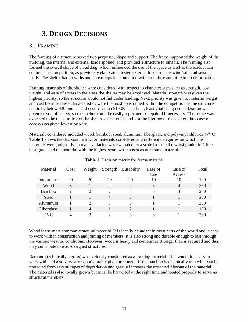
Table 1. Decision matrix for frame material
Material Cost Weight Strength Durability Ease of
Use
Ease of
Access
Total
Importance 20 20 20 20 10 10 100
Wood 3 1 2 2 3 4 230
Bamboo 2 2 2 3 3 4 250
Steel 1 1 4 3 1 1 200
Aluminum 1 2 3 3 1 1 200
Fiberglass 1 4 1 2 1 1 180
PVC 4 3 2 3 3 1 280
Wood is the most common structural material. It is locally abundant in most parts of the world and is easy
to work with in construction and joining of members. It is also strong and durable enough to last through
the various weather conditions. However, wood is heavy and sometimes stronger than is required and thus
may contribute to over-designed structures.
Bamboo (technically a grass) was seriously considered as a framing material. Like wood, it is easy to
work with and also very strong and durable given treatment. If the bamboo is chemically treated, it can be
protected from several types of degradation and greatly increases the expected lifespan of the material.
The material is also locally grown but must be harvested at the right time and treated properly to serve as
structural members.

12
Metal is another common structural material, though not as common for single-family dwellings. It is the
strongest of materials considered and, depending on the type of connection, can be easy to construct. The
type of metals examined are steel and aluminum. However, it is (depending on the type of metal) heavy
and expensive compared to the other materials considered.
Fiberglass rods were considered for their flexibility and strength. This material is commonly used in tents
because it is lightweight, flexible, and resists the bending stress of the structure. The material would not
be a candidate for the body of the shelter but would be ideal for the roof. A uniform material for the entire
frame is desired and thus fiberglass was not used in the shelter prototype.
Polyvinyl chloride (PVC) was the material chosen to construct the frame for the shelter prototypes. It is
strong and flexible enough to resist loads and absorb shock and not break. It is also the lightest of the
materials considered and the most cost effective. On top of all these aspects, it comes in a variety of sizes
with pre-fabricated joints for easy construction. PVC is very durable and does not rot or rust when
exposed to the elements over time. Since it is flexible over long spans, it does require more bracing and
more structure to support it.
Of all the materials considered, PVC was the material chosen to construct the frame. The frame itself was
composed of 178 ft of 1” Schedule 80 PVC, 58 ft of 1” Schedule 40 PVC, and 52 PVC joints. The
Schedule 80 PVC made up the body of the frame because it was thicker, hence stronger and not as
flexible, than Schedule 40 PVC. The body of the shelter sustained many of the loads, such as wind, rain,
snow, earthquake tremors, and the self-weight. The Schedule 40 PVC was used for the roof members
because it was more flexible than the Schedule 80 PVC and could form the curve of the roof. And to keep
the frame together, many of the members and joints were bolted (elaborated in section 3.5 Bolt Design) to
prevent members from slipping out of joints. The PVC frame was expected to withstand the conditions
applied. Refer to Figure 5 for an aerial photo of the frame when constructed.
Figure 5. Aerial view of assembled frame
3.2 COVER
The cover of the shelter formed the walls, ceiling, and floor, ultimately separating the occupants from the
outside environment. The cover had to be able to resist wind loads or transfer the load to the frame,
waterproof the shelter, insulate from temperature changes, block light, and provide adequate ventilation

13
for its inhabitants. Ultimately, two types of the cover were considered; a series of tarps or canvas material
or solid panels.
The series of tarps were layered over the frame forming a skin. Tarpaulin, also referred to as a tarp, is
canvas or polyester coated in polyurethane so it is flexible, strong, and waterproof. Tarps also come in
various thicknesses and coatings depending on the intended uses. The perimeter is lined with grommets to
secure it or tie it down. These characteristics made tarps an ideal choice because they could be
manipulated to cover many different shapes and sizes. The limitation of tarps was that, if it is not a single
piece, the seams where the tarp is layered are not waterproof and could expose the inhabitants to the
elements.
Solid panels could be joined together to form a structure or form the walls of a structure. The types of
panels considered include plain plywood, corrugated metal, and structural insulation panels (SIP).
Plywood is cheap, strong, and easily accessible. It does however need to be treated to prevent rot or
waterproofed with another material. Corrugated metal is a viable option and is used in current shelter kits.
It is strong and flexible, but it does not provide good insulation and is expensive and heavy, especially
considering the required size of the shelter. SIPs are an ideal form of panels because it is a sandwich of a
rigid insulation core between a layer of structural board. This board can be plywood, metal, or cement and
the core could be some sort of foam or honeycomb structure. All types of panels considered were not
chosen due to factors such as weight, cost, and packability (the panels are not compact and are large).
Tarpaulin was chosen to cover the shelter. The cover was composed of various sized tarps, each covering
a portion of the shelter prototype including the floor. The tarps ranged in size and were attached to the
shelter with the use of PVC clips that lock onto the frame. Heavy-duty tarps were chosen because the
shelter was expected to last 1-3 years and the diverse conditions observed in Nepal warranted the tougher,
albeit more expensive, version.
3.3 INSULATION
An integral portion of any habitable structure is insulation, particularly in areas plagued by extreme
temperatures. As Nepal can range in temperature from 36° to 100° Fahrenheit, proper insulation was a
crucial part of a successful and hospitable disaster shelter. Without proper insulation, the structure would
struggle to maintain comfortable temperatures during instances of extreme temperature differences
between the interior and exterior of the shelter. Choosing an insulation was essential to creating a shelter
prototype with little to no heat loss. The different types of insulation considered included Foamular, a
rigid foam insulation, mylar blankets, and double bubble insulation. Table 2 shows the decision matrix
for the three insulation options, including the categories in which they were judged. Each material factor
was evaluated on a scale from 1 (the worst grade) to 4 (the best grade) and the material with the highest
score was chosen as our insulation material.

14
Table 2. Decision matrix for insulation material
Material Cost Weight Packability Durability Effectiveness Ease of
Assembly
Total
Importance 20 20 10 20 20 10 100
Foamular 1 2 2 2 4 2 220
Mylar
blanket
4 4 4 2 1 3 290
Double
bubble
Insulation
3 3 3 4 3 3 320
Foamular is a commonly used rigid foam insulation. Because of its rigidity, Foamular would not be very
squishable and may be more likely to dent or break, hence lowering its rating in the packability and
durability categories. Its lack of flexibility would also make it hard to assemble or attach to the structure.
At 135 lb. and $468 for the necessary quantity, Foamular is the heaviest and most expensive option.
However, it is the most effective option with an R-value of 5.
Mylar blankets are commonly used by runners recovering after a marathon or by patients in shock. It
captures body heat by reflecting heat back to the user instead of releasing it. The blankets are very light,
packable, and affordable. The quantity needed would weigh approximately 4 lb. and cost $16. Its
flexibility would allow for easy assembly with the structure. However, because they are so thin, the
blankets would not be very durable or effective (with an R-value less than 1).
Double Bubble insulation is a step up from a mylar blanket. It is thicker with a bubble wrap-like layer
sandwiched between two layers of mylar or foil, giving it reflective, heat-capturing ability similar to a
mylar blanket. It would be more effective than a mylar blanket with an approximate R-value of 1.
Additionally, it reflects 96% of heat instead of letting it pass through. Its flexibility and thickness make
Double Bubble durable, packable, and easy to assemble with the structure. For the quantity needed,
Double Bubble reaches a median 30 lb. and $177. Hence the team decided that Double Bubble was the
best insulation option for the shelter prototype.
3.4 STRUCTURAL ANCHOR
The structural anchoring prevented the shelter from moving or tipping, especially during monsoon season
when there are high winds. The design wind velocity the structure was tested on is 75 km/hour. To anchor
the structure, three methods were considered; tie-down with a stake, stake as part of the frame, and
weighted bags.
Tie-down stakes are common in smaller structures like tents. This method relies on the tension of a cable
between two stakes placed on either side of the tent, effectively holding it in place. This method was not
chosen for a multitude of reasons; it increased the footprint of the shelter, it requires constantly tense
cords, and based on the size of the shelter, many tie-downs would be required. Additionally, the soil
conditions in Nepal vary greatly and due to changing conditions, such as saturated soils, the stakes would
not provide enough resisting force to keep the cord in tension.
Stakes that are part of the frame protrude down into the ground and hold the shelter in place. The stakes
are effective in preventing the shelter from sliding along the ground as well as from overturning caused
by high winds. This method can be limited depending on the ground/soil conditions. The stakes would not
be utilized if the ground surface is too solid to be penetrated such as rock or hard clay.

15
Weighted bags placed along the frame of the shelter is the simplest method of anchoring the structure.
The bags are sand bags, but the material filling the bags, providing the weight, could be anything locally
available such as soil, sand, or aggregate. These could be placed around the perimeter of the shelter on the
frame and/or the tarps to form a waterproof barrier. Since it could not always be assumed that stakes
could be implemented due to unpredictable soils, the design scenario for the weighted bags was to be
resisting to a wind into a 16-foot side. The loading due to wind calculations are outlined in Appendix A1.
Refer to Figure 6 for a diagram of this design situation.
Figure 6. Diagram of weighted bags resisting overturning
Assuming the weighted bags to be a uniform weight along the perimeter of the structure, the bags needed
to be approximately 9 lb/ft, including a factor of safety of 2. Refer to Appendix A2 for the development
of the associated calculations.
The preferred method to anchor the system was a combination of weighted bags and stakes attached to the
frame. The stakes were placed at the four corners and at the centers of the two long edges. The weighted
sand bags were placed around the perimeter of the shelter, laying both on the frame and tarp walls. The
combination of the two anchoring methods was expected to withstand the wind loads as well as the
earthquake simulations.
3.5 BOLT DESIGN
After initial testing and assembly of the PVC frame, the team quickly ascertained that a system fastening
all joints in place would need to be employed to prevent members from disconnecting from joints when
placed under stress. Candidates for this task included deliberations between manually gluing each joint or
using hex bolts as pins, which would be slipped through predrilled holes of the PVC members and their
corresponding joints. A system employing glue was quickly ruled out due to the irreversibility of
permanently attaching members to joints. Therefore, the team decided to employ a fastening system by
use of hex bolts. Refer to Figure 7 below for a visual representation of a bolted joint and member.

16
Figure 7. Visual representation of bolted 3-way joint
The design criteria for the hex bolts hinged mostly on the ability for the bolts to resist failure while in
double shear. Using data from the StaadPro model to find the maximum axial force for any member, the
team found the required bolt size and grade to avoid failure. Refer to Appendix A3 for a development of
those associated calculations. After completing the accompanying calculations, the team decided to use ¼
inch diameter, 2-inch-long hex bolts composed of Grade 5 steel plated with zinc. The bolts were found to
be more than sufficient to resist the require shear, and the zinc plating allowed the bolts to be resistant to
rust and corrosion. Nearly all members were bolted in their joints, with the exception of the arched
schedule 40 PVC members in their connections to the top of the walls on the longest sides of the shelter.
Table 3 shows the results of the calculations associated with the bolt design. As Table 3 shows, the
selected bolts were more than capable of resisting the forces they will be subjected to during maximum
loading. The team was comfortable with this overdesign of bolt strength, as the ¼ inch diameter bolts
were a standard size for use, and there was not a significant price difference for lessening diameter bolts.
Table 3. Results of Design Calculations for ¼ inch Diameter Grade 5 Steel Bolts
Area of Bolt
(in2)
Max Axial
Force (lbs)
Factor of
Safety
Max Shear
Stress
Calculated
(psi)
Ultimate
Tensile
Strength
Required (psi)
Actual Tensile
Strength of ¼
inch diameter
Grade 5 steel
bolts (psi)
.04909 32 3 977.8 1629.7 120,000
3.6 FLOOR TILES
A critical component of any living space is an effective and comfortable floor. Quality flooring is
especially significant regarding heat retention, as conductive heat loss can be problematic through the

17
contact of the living space and the ground. It is also important in stopping the spread of disease by
keeping things dry. When evaluating alternatives for flooring, the team came up with three main options.
The options consisted of simply a heavy-duty tarp, rubber floor tiling, or foam tiling. Heavy-duty tarp
alone was quickly ruled out due to the lack of comfort and thermal retention such a flooring system would
offer. While rubber tiles would provide considerable comfort, stability, and longevity, it too was decided
against due to its higher price and weight. Consequently, the team decided to select foam tiling as the
preferred flooring. Foam tiling would allow the occupants of the shelter to have a comfortable and
insulating floor without compromising the financial costs and weight of the flooring. The selected foam
flooring was an interlocking system of 2’ x 2’ and ½ inch thick mats. Refer to Figure 8 for a visual
representation of the foam tile mats while set-up.
Figure 8. Visual representation of interlocking foam tiles
3.7 CROSS BRACING
A key component of any structure, is providing efficient and effective cross bracing. Cross bracing gives
structural members much needed support, and provides more pathways for loads to reach the ground. To
find the best cross members, the team decided primarily between using steel rods, nylon string, and
ratchet straps. Steel rods were ruled out due to their excessive weight, cost, and difficulty to connect.
Nylon string also proved difficult to connect to the frame, and did not provide as much structural support
as the other options. Consequentially, the team decided on ratchet straps for use in cross bracing, as they
were reasonably priced, were relatively easy to use and connect, and provided an adequate amount of
support to the structure. The ratchet straps had a metal S-hook on both ends, and could be fastened to
various members along the frame. The proposed method is the attachment in an “X” like pattern on the
center two panels along the 16 ft long sides, and on the corner panels for both the front and back of the
frame. This arrangement provided great structural reinforcement to the framing. Refer to Figure 9 for a
visual representation of the cross bracing connecting to the proposed locations.

18
Figure 9. Visual representation of cross bracing
4. PROTOTYPE CRITERIA
The completed shelter met all criteria outlined in the Project Requirements. The following sections
outline that the criteria have been met in all areas.
4.1 PHYSICAL REQUIREMENTS
The shelter had to meet certain physical requirements. Below, Table 4 summarizes the met requirements.
First, the shelter had to fit on the 16 ft x 20 ft (5 m x 6 m) shake table and in the heat retention testing area
with a height of no more than 10 ft (3 m). The designed prototype was 16x10x8 ft (5 m x 3 m x 2.4 m).
Second, the shelter had to house 4 people comfortably, meaning that each person needed 37.7 ft2, totaling
approximately 151 ft2. The prototype was 161 ft2 total, giving each person 40.4 ft2. It also had to have 6.6
ft of head space for 70% of floor space. The designed prototype had 6.6 ft or more for 96.9 percent of the
floor space. Lastly, the full package housing the shelter had to not exceed 440 lb. (200 kg) in total. The
designed shelter weighed about 385 lb. (174.6 kg).
Table 4. Physical requirements summary
Item: Requirements: Actual:
Dimensions Less than 16ft x 20ft 16ft x 10ft
Space/person 37.7 ft2 40.4 ft2
Total Area 151 ft2 161.5 ft2
Head Space 6.6ft for 70% 6.6ft for 96.9%
Weight 440 lb. 384.7 lb.

19
4.2 STRENGTH REQUIREMENTS AND WEATHER RESISTANCE
To model the various components of this project, the team used two main programs to model the shelter
portion, and base camp layout portion. Regarding the modeling of the shelter, the program StaadPro was
employed as the program of choice. This program was chosen as all members of the team were familiar
with the program from class curriculum at Calvin and knew that it would suit the purposes of our design
well. Through the model, the team could test varied sizes of PVC piping in addition to the effects of
changing the wall thickness under design loads. The design loads for the shelter were based primarily off
the wind loads the shelter would be subjected to at the competition. According to the competition design
criteria, the shelter was expected to withstand a 50 mph (75 km/hour) wind. With that load as a baseline,
the structure was tested under that design criteria with varying members. Refer to Figure 10 below, for a
snapshot of the model showing performance against the simulated wind load. This model shows the
decided final members, which were 1” PVC schedule 80 piping. The cross-webbing portions modeled of
the structure were nylon ratchet straps which acted as cross bracing for the structure. These ratchet straps
functioned as valuable components of the structure, increasing resistance to wind loads. The wind load
was modeled as 7.5 lb/ft (10.2 N/m) load on the windward side for every member off the ground. This
instance rendered a maximum deflection of 5.2 inches (13.2 cm) which the team deemed acceptable for
use. Therefore, according to modeling and extra measures built into the structure, the shelter prototype
met the strength requirements and would remain upright and usable in high winds. In addition to high
winds, the shelter was designed with large quantities of rainfall in mind. The shelter was covered with
waterproof, heavy duty tarps. The floor also had a layer of tarp that created a lip on all sides to protect
from rain seeping into the structure. Therefore, the shelter was completely rain proof against possible 4
in/hr rainfall.
Figure 10. StaadPro model of final design

20
4.3 HEAT LOSS AND VENTILATION REQUIREMENTS
It was required that the shelter be capable not only of ventilation but also retaining heat. The zipper door
was designed to be folded up for added ventilation. The shelter was designed so that the tarps would be
customizable as well. They could be folded up to create a gap for air movement and folded back down to
retain heat. The insulation added was also detachable, but when attached, it prevented most heat loss by
reflecting heat back into the shelter. The foam floor tiles were also chosen to retain as much heat as
possible.
4.4 LIFE SPAN REQUIREMENTS
The shelter was required to last one to three years. The materials used to construct the shelter were
specifically chosen with longevity in mind. For example, bamboo was not chosen, in part, because it must
be treated properly to last a few years. However, all the materials chosen for the shelter prototype were
made of plastics and metal both of which were long lasting and durable. For example, the tarping used
was expected to last between 1 to 3 years. If for any reason the shelter is no longer needed or usable, most
of the materials used are also recyclable (if done properly). This prototype should easily last one to three
years, if not more, provided that it is able to withstand the weather and any other unforeseen
circumstances.
4.5 ASSEMBLY REQUIREMENTS
The designed shelter had to be easy and rapid to assemble without technical knowledge. The team’s
prototype took approximately 1 hour to construct with 4 people. It required no more than a hammer and
comes with a set of simple directions for assembly (see Appendix D).
4.6 PACKABILITY REQUIREMENTS
The shelter had to be easily stored, transported, and flat packed into a, 8x40-ft shipping container. The
designed shelter was easily packed into an 8x2.5x2-ft plywood box. The box was fitted with handles for
easy transportation to the disaster location. It also could be packed efficiently into a shipping container,
leaving limited space for shifting. Sixty kits would fit into one shipping container. There could be 3 boxes
wide, 5 boxes long, and 4 boxes high.
4.7 REUSABILITY AND EXPANDABILITY
The team had to design the shelter so that it was reusable in the event of another disaster and so that it
could be added upon using local materials and methods. The designed shelter was easily reusable because
of its durability and packability. There were also many ways for it to be expanded upon. The tarp used for
cover was specifically designed so that it could be attached and reattached in a different configuration. If
a larger structure is needed, two frames could be built side by side and tarps added as needed. Insulation
could also be attached and reattached if it is not needed in the summer time. If more insulation is needed,
local straw could be used as a supplement. The anchoring system could also be supplemented using the
extra sand bags included in the kit. If a more permanent structure is needed, corrugated sheet metal could
be added to the roof. The designed shelter could be modified and expanded in many ways.
21
4.8 COST
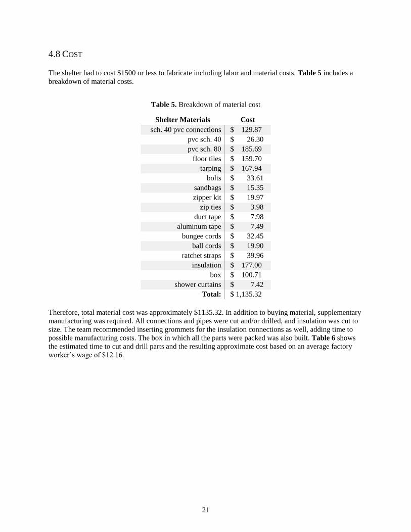
The shelter had to cost $1500 or less to fabricate including labor and material costs. Table 5 includes a
breakdown of material costs.
Table 5. Breakdown of material cost
Shelter Materials Cost
sch. 40 pvc connections $ 129.87
pvc sch. 40 $ 26.30
pvc sch. 80 $ 185.69
floor tiles $ 159.70
tarping $ 167.94
bolts $ 33.61
sandbags $ 15.35
zipper kit $ 19.97
zip ties $ 3.98
duct tape $ 7.98
aluminum tape $ 7.49
bungee cords $ 32.45
ball cords $ 19.90
ratchet straps $ 39.96
insulation $ 177.00
box $ 100.71
shower curtains $ 7.42
Total: $ 1,135.32
Therefore, total material cost was approximately $1135.32. In addition to buying material, supplementary
manufacturing was required. All connections and pipes were cut and/or drilled, and insulation was cut to
size. The team recommended inserting grommets for the insulation connections as well, adding time to
possible manufacturing costs. The box in which all the parts were packed was also built. Table 6 shows
the estimated time to cut and drill parts and the resulting approximate cost based on an average factory
worker’s wage of $12.16.

22
Table 6. Time and cost to manufacture
Time/action (s) Quantity Total time (hr) Total Cost
Drilling PVC
connectors and pipe 30 322 2.6833 $33.84
Cutting PVC pipe 36 166 1.6600 $20.93
Cutting Insulation 15 21 0.0875 $1.10
Insert grommets 30 100 0.833 $10.51
insert zippers 300 2 0.167 $2.10
box assembly
0.5 $6.31
packing
0.250 $3.15
25% overhead $19.49 Total: $97.43
In addition, using an average build time of 30 minutes for the box in which the parts would be
transported, manufacture costs are an additional $6.31. An additional 25% contingency for overhead costs
would bring the manufacture costs to $97.43.
Once the boxes would be packed, Samaritan’s purse would need them shipped to Nepal via a 8 ft x 40 ft
shipping container. This shipping cost would be between $2000 and $25009. If 72 kits fit into one
shipping container, the shipping cost for each box would be $42 at most.
Therefore, the total cost of one shelter, including shipping costs was approximately $1275, which met the
cost criteria.
4.9 CULTURAL APPROPRIATENESS
The designed shelter should accommodate the culture in which it is being used. To design for the culture
in Nepal, the prototype was designed to have three rooms. As per Nepalese custom, there was a common
room at the front and two small bedrooms – one for women and the other for men. These rooms were
separated using shower curtains or hanging tarps to provide privacy. The overall structure of the shelter, a
rectangular building with a peak, also followed standard residential architecture in Nepal.
9 “2018 International Container Shipping Rates and Costs.” MoverDB.com, MoverDB.com, 8 Jan 2018,
moverdb.com/container-shipping/.

23
5. CAMP PLAN
5.1 DESCRIPTION Architecture and urban planning go hand in hand. The design of a structure and the relationships between
structures and the rest of the built environment can have an impressive influence on the lives of those
within them. Therefore, the team took seriously its charge to design the shelter and the camp plan to
provide as dignified and pleasant an experience as possible in the disaster situation.
The inspiration behind this design was found partly in the street design of Downtown Detroit by Augustus
B. Woodward, and partly in Mexican architect Fernando Romero’s conceptual design of a binational
border city between the United States and Mexico:
Figure 11. Augustus B. Woodward’s Plan of Detroit10 & Fernando Romero’s Border City11
The guiding principles for the design came from the team’s deeply held beliefs in egalitarianism,
accessibility, and dignity for all, as well as adherence to the guidelines presented in the Sphere Handbook.
The belief that all ought to have equal access to goods and services was manifest in the plan’s triangle-
hexagon modular layout. The plan made use of the proportionality of triangles and spatial efficiency of
hexagonal packing to allow for relatively easy and direct access to resources in the camp.
The team designed two camp plans: one idealized, and one specialized for Nepalese geography. The
former assumed a relatively large swath of flat (slopes between 1-6%) land, which was only likely to exist
in the lowland portion of Nepal, near the border with India. The latter displayed perhaps the most superior
aspect of the team’s design: versatility. With the team’s modular approach, this camp plan could be
adjusted to almost any topography. The plan was built out of modular units, differing in size, which could
be arranged to twist around intrusive geographical features, such as mountains or valleys.
10 Unknown – Dickens, Asbury & Forney, John W., eds. (1832) “Plan of Detroit (Map). American State Papers.
Vol. 6: Public Lands. 1:6,000. Washington, DC: Gales &Seaton. P. 299. OCLC 2053058. OL7014594M. LCCN
</noinclude> 09033892 – via Archive.org.
11 Fernando Romero et al. Border City, www.fr-ee.org/project/73/Border+City. Accessed 1 Apr. 2018.

24
The main modular units are shown below, and are, left to right, the A-Unit, B-Unit, and C-Unit:
Figure 12. Modular units of camp plan
An A-Unit is roughly triangular and the most basic of the units, containing fifteen 10’ x 16’ (5 m x 3 m)
shelters along the periphery of the triangle, along with three outhouses and two 25-gal (100-L) trash cans
in the center. The shelters were spaced 9 ft (3 m) apart from each other, meeting the minimum separation
of 6 ft (2 m) specified by the Sphere Handbook. The three outhouses met the requirement of a maximum
of 20 people per toilet and were very close to living quarters (far less than 160 ft (50 m) from dwellings).
To accommodate human waste, pits would be dug in the initial stages of construction. The two 25-gal
(100-L) trash cans met the minimum of one per 10 households and would be emptied into nearby
communal dumpsters.
In additional storage areas (see Appendix B3), communal dumpsters, wash basins, and water tanks could
be located. The wash basins met the minimum of one wash basin per 100 people. For potable water,
inhabitants of the camp would get water from water tanks located near the shelters. All of these were
located well beneath the maximum distance to water of 1650 ft (500 m). The sizes of the water tanks were
1200-gal (4500-L) and 5000-gal (19000-L), which accommodated all inhabitants and would require
refilling weekly to give the minimum 4 gallons (15 liters) of water per person per day, according to
Sphere Handbook guidelines.
A B-Unit is simply three A-Units arranged in a semicircular fashion, with 12 ft (4 m) wide walking paths
separating the A-Units. Towards the top of the B-Unit in Figure 12 is a half-hexagon shaped area that
could be used for locating wash basins, potable water tanks, and communal dumpsters. The communal
dumpsters were sized to hold all the refuse accumulated in a week from 25-gal (100-L) trash cans in the
adjacent A-Units.
Finally, a C-Unit is simply two B-Units arranged opposite of each other. The spacing between them was a
minimum of 100 ft (30 m), easily meeting the Sphere requirement of 100 ft (30 m) of firebreak between
every 1000 ft (300) m of built-up area.
Arranging these modules into a whole, the team arrived at this triangular-hexagonal idealized camp plan,
sized approximately 2300 ft (700 m) across:

25
Figure 13. Idealized camp plan
At its essence, the idealized camp plan was 12 C-Units arranged in a fashion resembling a honeycomb or
snowflake. Between C-Units were 24 ft (7 m) wide roadways intended for an SU-30 design vehicle,
which are roughly the size of delivery trucks (Figure 14). With this design vehicle in mind, the curb
radius for 60° turns was 60 ft (20 m), for 90° turns was 50 ft (15 m), and for 120° or greater turns was 30
ft (9 m)12. This would allow delivery trucks to turn right without swerving into the opposing lane.
However, cars were not expected to constantly use these roads, and, in their presence and absence, were
intended for pedestrian traffic and right-of-way.
A larger version of the idealized camp plan, along with the site-specific camp plan, can be found in
Appendix B1. For a larger version of a B-Unit in the camp plan, with all components visible, see
Appendix B2. For dimensions of all the components listed in the legend, see Appendix B3. For the
dimensions of the encampment and storage areas in the idealized camp plan, see Appendix B4. Finally,
for the spatial arrangement of the encampment and storage areas in the idealized camp plan, see
Appendix B5.
12 Garber, Nicholas J. Traffic and Highway Engineering, 5th Edition. Cengage Learning, 2015. [Bookshelf Online]
F
FF
F
F F
MM M
MM M
U
+
SHELTER
OUTHOUSE
REFUSE CONTAINER (100 L)
WATER TANK (4,500 L)
WATER TANK (5,000 gal)
WASH BASIN (5 ct.)
COMMUNAL REFUSE CONTAINER
SHELTER AREA BOUNDARY
ROAD AREA BOUNDARY
MEDICAL FACILITY
BATHING/LAUNDRY FACILITY
+F/M/U

26
Figure 14. SU-30 Design Vehicle13
Also included in the roadway design were roundabouts at the confluence of six roadways. Multiple
options existed for filling these circular areas. Included in the team’s design were shower/laundry
facilities, segregated by gender: male, female, and unisex. The female facilities were located in
conspicuous locations to prevent the women from feeling isolated and endangered, and to deter potential
attackers from intruding into those facilities. The unisex facilities were intended for families and mita.
Mita are transgender individuals with legal “third-gender” status in Nepalese society, and out of the
team’s commitment to dignity for all people, designed a safe shower/laundry facility for their use. In the
center of the camp, a medical center was located to provide for immediate and preventative care for all
people in the camp, along with distributing necessary goods to occupants.
Finally, understanding the need to adapt to Nepal’s very site-specific topography, an example of one
modified site plan is shown below:
13 Urban Street Design Guide, National Association of City Transportation Officials,
https://nacto.org/publication/urban-street-design-guide/design-controls/design-vehicle/. Accessed 1 Apr. 2018.

27
Figure 15. Site-specific camp plan variant
This variant used a minimum modular size of B-Units, given the spaciousness between mountains.
However, if the terrain is even steeper, a minimum of an A-Unit could be used as well. This site-specific
variant was spacious enough to include all relevant features with adequate spacing, just like the idealized
camp plan, though was not as accessible for all by geography.
28
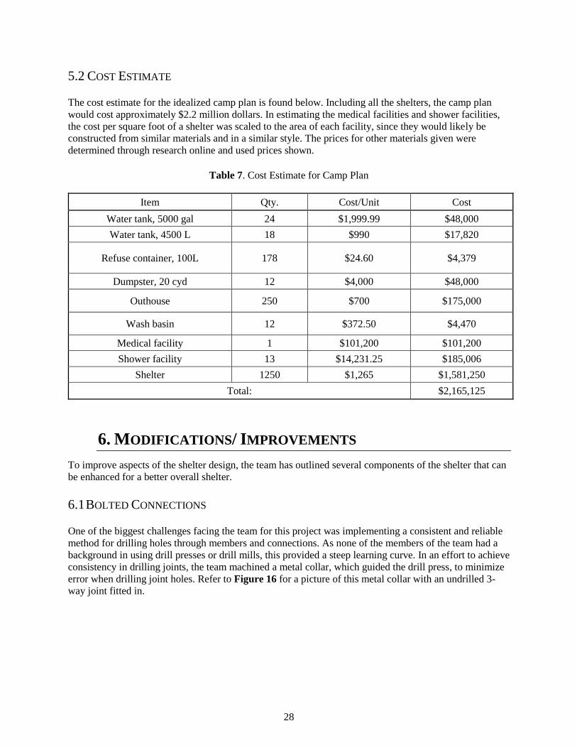
5.2 COST ESTIMATE
The cost estimate for the idealized camp plan is found below. Including all the shelters, the camp plan
would cost approximately $2.2 million dollars. In estimating the medical facilities and shower facilities,
the cost per square foot of a shelter was scaled to the area of each facility, since they would likely be
constructed from similar materials and in a similar style. The prices for other materials given were
determined through research online and used prices shown.
Table 7. Cost Estimate for Camp Plan
Item Qty. Cost/Unit Cost
Water tank, 5000 gal 24 $1,999.99 $48,000
Water tank, 4500 L 18 $990 $17,820
Refuse container, 100L 178 $24.60 $4,379
Dumpster, 20 cyd 12 $4,000 $48,000
Outhouse 250 $700 $175,000
Wash basin 12 $372.50 $4,470
Medical facility 1 $101,200 $101,200
Shower facility 13 $14,231.25 $185,006
Shelter 1250 $1,265 $1,581,250
Total: $2,165,125
6. MODIFICATIONS/ IMPROVEMENTS
To improve aspects of the shelter design, the team has outlined several components of the shelter that can
be enhanced for a better overall shelter.
6.1 BOLTED CONNECTIONS
One of the biggest challenges facing the team for this project was implementing a consistent and reliable
method for drilling holes through members and connections. As none of the members of the team had a
background in using drill presses or drill mills, this provided a steep learning curve. In an effort to achieve
consistency in drilling joints, the team machined a metal collar, which guided the drill press, to minimize
error when drilling joint holes. Refer to Figure 16 for a picture of this metal collar with an undrilled 3-
way joint fitted in.

29
Figure 16. Metal collar used to guide drill press for drilling joint connections
Manufacturing errors were still present despite precautions taken in to account for them. The joints and
members are still operational despite this, but more difficult to work as the assembly became more
challenging. For this reason, the team believes this could be an area that could be vastly improved should
the shelter ever be mass produced.
6.2 INSULATION
As previously outlined in the report, Nepal temperatures can vary drastically depending on the time of
year and elevation. To keep the shelters isolated from the extreme temperature variations inhabitants
could face, insulation was a key factor. The current insulation includes the double bubble foil insulation
which is effective in preventing heat from passing through it by reflecting approximately 96% of the
radiant heat it encounters14. However, this insulation does not perform well in slowing the way heat
passes through it. As a result, the team recommends that inhabitants improve this by implementing their
own form of insulation to help bolster the heat retention capability of the shelter. Such a material that
could be used, would be straw, which is readily available in areas of Nepal and is well known insulation.
6.3 VENTILATION
The shelter is efficient in the categories of heat retention and water-proofing, but the tradeoff is
ventilation. The only existing point for ventilation is the front door which may lead to poor air circulation.
The team recommends to mitigate this issue by rolling up the insulation and the outside tarp under
appropriate weather conditions so as to let the wind permeate the tarping exteriors. Or, if it is dry outside,
lower the bottom tarp to create more ventilation points. It is advised in future designs to implement
retractable flaps or openings to better facilitate air flow.
14 “Double Bubble Insulation - Foil/Foil - 4' x 75' (300 Sq Ft).” Ecofoil, www.ecofoil.com/Double-Bubble-Foil-
Insulation-Foil-Both-Sides-4-x-75-300-sq-ft.

30
6.4 LIGHTING
A short-coming of the shelter is the lack of lighting when inside the shelter. The lack of lighting can be
similarly attributed to the effective insulation and water-proofing. Besides the entry way, there are no
points in which light can enter the structure. The combination of tarping and insulation block nearly all
light from the outside and thus, during poor weather or night-time, the interior of the shelter can be very
dark. The team recommends using a non-flammable light source such as a lantern or a product such as the
gravity light to provide light to the interior. Future designs may be able to include such objects or
incorporate a simple light source into the structure’s frame.
6.5 DURABILITY
The shelter was meant to be a transitional shelter and not a permanent dwelling place. That being said, the
materials used in the shelter prototype are durable, but can be improved to have a longer lifespan and
implemented beyond the transitional phase. Attributes such as replacing the layered, taped holes on the
insulation with grommets for example would fit into this category. Additional recommendations to
increase the durability of the shelter materials would be to combine the insulation and tarp to reduce the
number of components. And similarly, create a single tarp to fit over the structure, minimizing the
number of components needed and the number of fasteners required. The bungie cords can be replaced
with paracord to fasten the tarp to the frame without concern of the bungie cords losing tension. The tarps
can also be upgraded to withstand UV exposure better over the lifespan of the structure so as to not lose
strength or performance. All of the listed above are options the team recognizes can impact the durability
of the structure.

31
7. CHRISTIAN PERSPECTIVE
The team’s Christian faith guided their participation in the competition as well as their design decisions.
The following design norms outline specific ways that the team applied their Christian perspective to the
design of their shelter and camp plan.
7.1 DESIGN NORMS
Cultural appropriateness was the first and most relevant of the design norms. Since the team was
designing something that will be used in a different culture, understanding the cultural context was
important so that the object met an actual need in a way that was natural and fitting for people in Nepal.
Designing without cultural appropriateness could be, at best, a waste of time, and at worst, an injurious
act to those whom the team sought to serve.
Transparency was another very important design norm. Transparency was essentially being open and
upfront about the capabilities of the design and whether or not it adequately met all the requirements and
fit the cultural situation. The team had no desire to deceive or mislead competition officials or the people
of Nepal. In order to best serve the team's clients, the team sought to be upfront with any concerns and
costs about the design.
Stewardship implies that the team produced a quality product given the budget allowed for each shelter,
and chose materials and methods required to erect these structures that have minimal impact on the local
and global environments. Stewardship required the team to answer questions relating to the life-cycle of
its product. What will happen to the materials after the product's useful life is over? Will the disposal of
the shelter lead to undue hardship among any people in Nepal?
Integrity is doing exactly what one says one will. This means that the team was obligated to follow
through on design promises and requirements. It also means that the team would not inflate expectations
or say that the design would be able to do things that it will not do. Integrity means not taking shortcuts or
the easy way out in design.
Justice was an enormous consideration in the team's design. As the team designed for a people who have
been afflicted by natural disaster. Justice in the team's design ensured that the team's product attempted to
rectify as many wrongs as possible that the Nepalese people have endured.
Caring goes above and beyond the concerns of justice. Not only was it important for the team to design in
terms of what met the needs of earthquake-survivors, but also what would provide them with the highest
quality of life. The team hoped to make living in the shelter as comfortable of an experience as possible,
given the disaster situation and constraints.
Trust was crucial for the team to be successful in this project. The team was entrusted to make a design
that thousands of people may live in for 1 to 3 years. The team designed their shelter in a way that future
inhabitants could trust that it would not collapse during inclement weather.
Humility was the understanding that the team was not always correct, and that seeking out wisdom from
others was crucial. For the team, this meant understanding and realizing that there was only so much that
a team with limited knowledge of the target area and people, could do on its own. This design norm
motivated the team to seek out knowledge from others who were more qualified in terms of Nepal-
related or disaster-relief-related knowledge.

32
8. COMPETITION RESULTS
The team competed over the days of April 19 to 21 of 2018 against nine other teams from various
universities. The team was judged over the following criteria; report, presentation, cost, physical
parameters such as height, weight, wind-loading, seismic-loading, heat-retention, rain resistance, aspects
of functionality such as ease of assembly, ventilation, privacy, durability, packaging, livability,
upgradability, and cultural appropriateness. To measure many of the criteria mentioned, the shelter
prototype underwent tests such as the shake table, heat retention booth, wind-loading machines, rain
machines, and judge examinations.
The team placed second overall and won several individual awards as scored by the panel of judges is
found in Appendix C. The individual awards include Best Camp Plan, Lightest Shelter, and Best
Report/Presentation.
9. CONCLUSION
The team has designed a shelter prototype and camp plan to provide Nepal with a usable and culturally
appropriate response to a disaster. The team’s efforts may contribute to the recovery period in Nepal, in
the event of another earthquake or natural disaster. The shelter provided enough living space for a family
of four. It was water-proof, could withstand high winds and earthquake tremors/aftershock, and provided
insulative cover in the cold temperatures. The prototype was lightweight, durable, packable, and cost
effective. Additionally, the camp plan was all inclusive and modular to fit a specific situation and terrain.
As a result of the above analysis, the team believed that all of the project constraints given by John Brown
University were met. The team has learned a great deal of the humanitarian relief efforts, of being a part
of a team, and are proud of the competition results achieved.

33
ACKNOWLEDGEMENTS:
The team would like to thank the Eric DeGroot Engineering Fund for their support to our project
and for the continuous support to Senior Design Teams.
The team would like to acknowledge the faculty advisor, Professor De Rooy, as well as the
Calvin College Engineering Program for the support and opportunity to pursue this competition.
The team would like to thank Jim and Marcia Vander Meulen for providing transportation to and
from the competition site.
The team would like to thank Rick Blauwkamp for providing a trailer to transport the shelter
prototype to and from the competition site.
The team would like to thank Michelle and Wyman Dobbs for hosting and feeding the team while
at the competition.
The team would like to thank Samaritan’s Purse and Intertek for sponsoring the competition as
well as John Brown University for hosting the competition on their campus.
The team would like to thank Bob DeKraker for ordering and managing shelter components.
The team would like to thank Phil Jasperse for his consultations and support in the manufacturing
of the shelter prototype and components.
34
REFERENCES:
“2018 International Container Shipping Rates and Costs.” MoverDB.com, MoverDB.com, 8 Jan 2018,
moverdb.com/container-shipping/.
“Double Bubble Insulation - Foil/Foil - 4' x 75' (300 Sq Ft).” Ecofoil, www.ecofoil.com/Double-Bubble-
Foil-Insulation-Foil-Both-Sides-4-x-75-300-sq-ft.
Fernando Romero et al. Border City, www.fr-ee.org/project/73/Border+City. Accessed 1 Apr. 2018.
Frearson, Amy. “Prototype shelter for Nepal earthquake victims could be built by unskilled workers in
three days”. Dezeen. 11 July 2015. Dezeen. Web. 6 Dec. 2017.
<https://www.dezeen.com/2015/07/11/prototype-bamboo-shelter-nepal-earthquake-victims-built-
by-unskilled-workers-three-days/>.
Garber, Nicholas J. Traffic and Highway Engineering, 5th Edition. Cengage Learning, 2015. [Bookshelf
Online]
Laylin, Tafline. “10 refugee shelters I love, for the good and the bad”. Green Prophet. 14 March 2014.
Green Prophet. Web. 6 Dec. 2017. <https://www.greenprophet.com/2014/03/pros-and-cons-10-
refugee-shelters/>.
“Map of Nepal”. WELNepal. 2011. WELNepal. Web 20 Nov. 2017.
<http://www.welnepal.org/homeMap.html>.
“Nepal Earthquakes: Devastation in Maps and Images.” BBC News World. 15 May 2015. BBC. Web. 13
Nov. 2017. <http://www.bbc.com/news/world-asia-32479909>.
Proud, Richard, Zuberi, Matinuzzaman. “Nepal”. Encyclopǽdia Britannica. 24 March 2017.
Encyclopǽdia Britannica, Inc. Web. 7 Dec. 2017. <https://www.britannica.com/place/Nepal/The-
people>.
“Sheltering Nepal”. Samaritan’s Purse. 26 Nov. 2015. Samaritan’s Purse. Web. 13 Nov. 2017
<https://www.samaritanspurse.org/article/sheltering-nepal/>.
Sokol, Brian. “Struggling amid the ruins a month after Nepal quake”. Al Jazeera. 25 May 2015. Al
Jazeera media Network. Web 26 March 2018.
<https://www.aljazeera.com/indepth/inpictures/2015/05/struggling-ruins-month-nepal-quake-
150525062223409.html>.
Unknown – Dickens, Asbury & Forney, John W., eds. (1832) “Plan of Detroit (Map). American State
Papers. Vol. 6: Public Lands. 1:6,000. Washington, DC: Gales &Seaton. P. 299. OCLC 2053058.
OL7014594M. LCCN </noinclude> 09033892 – via Archive.org.
Urban Street Design Guide, National Association of City Transportation Officials,
https://nacto.org/publication/urban-street-design-guide/design-controls/design-vehicle/. Accessed
1 Apr. 2018.

35
TABLE OF APPENDICES:
A. CALCULATIONS A1. Wind Calculations
A2. Anchoring Calculations
A3. Bolt Design Calculations
B. CAMP PLAN B1. Idealized & Site-Specific Camp Plans
B2. Large Scale B-Unit with Encampment and Storage Areas
B3. Camp Plan Component Dimensions
B4. Encampment & Storage Area Dimensions
B5. Encampment & Storage Area Spatial Distribution
C. COMPETITION SCORING MATRIX
D. CONSTRUCTION DIRECTIONS

36
APPENDIX A1: WIND CALCULATIONS
CODE: ASCE 7-10: 27.3.2 VELOCITY PRESSURE:
𝑞𝑧 = 0.00256𝐾𝑧𝐾𝑧𝑡𝐾𝑑𝑉2 (𝑙𝑏
𝑓𝑡2) (27.3-1)
𝑞𝑧 = Velocity Pressure
𝐾𝑧 = Velocity Pressure Exposure Coefficient
𝐾𝑧𝑡 = Topographic Factor Defined
V = Basic Wind Speed
𝐾𝑑 = Wind Directionality Factor
From Table 27.3-1: Height Above Ground Level is 0-15 feet, and has Exposure C. Therefore 𝐾𝑧 = 0.85
From Section: 26.8.2: All conditions not met. Therefore 𝐾𝑧𝑡 = 1.0
From John Brown University Design Guidelines: V = 46.6 mph (75 Km/Hour)
From Table 26.6-1: For Arched Roofs, 𝐾𝑑 = 0.85
𝑞𝑧 = 0.00256 𝑥 (0.85) 𝑥 (1.0) 𝑥 (0.85) 𝑥 (46.6)2 = 4.02 𝑙𝑏
𝑓𝑡2 (192.17 𝑁
𝑚2)
TOTAL LOADS ON EACH WALL WHEN RESISTING WIND:
Area of Side Wall: 16ft x 6ft = 96 ft2
Area of Front and Back Wall: 10ft x 6ft + 17.3 ft2 = 77.3 ft2
Total Load on a Side Wall: 4.02 lb/ft2 x 96 ft2 = 385.9 lb (1,716.7 N)
Total Load on Front and Back Wall: 4.02 lb/ft2 x 77.3 ft2 = 310.8 lb (1,382.3 N)

37
APPENDIX A2: ANCHORING CALCULATIONS
From Appendix A1: Load on Side Wall due to Wind = 385.9 lb
Factor of Safety = 2
Figure A2. Diagram of design scenario for overturning
Overturning Moment = 385.9 lb x 3ft = 1157.7 lb-ft
Factored Overturning Moment = 1,157.7 lb-ft x 2 = 2,315.4 lb-ft
Uniform Weight of Bags = Bw
Therefore,
Bw x (10ft x 5ft) x 2 + Bw x 16ft x 10ft = 2,315.4 lb-ft
Solving for Bw: Uniform Weight of Bags necessary to avoid over tipping is 8.9 lb/ft
Bw = 8.9 lb/ft
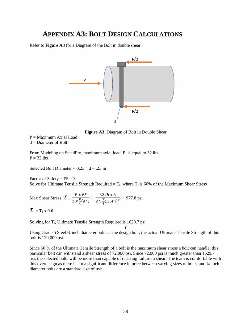
38
APPENDIX A3: BOLT DESIGN CALCULATIONS
Refer to Figure A3 for a Diagram of the Bolt in double shear.
Figure A3. Diagram of Bolt in Double Shear
P = Maximum Axial Load
d = Diameter of Bolt
From Modeling on StaadPro, maximum axial load, P, is equal to 32 lbs.
P = 32 lbs
Selected Bolt Diameter = 0.25”, d = .25 in
Factor of Safety = FS = 3
Solve for Ultimate Tensile Strength Required = Tr, where Tr is 60% of the Maximum Shear Stress
Max Shear Stress, 𝜏= 𝑃 𝑥 𝐹𝑆
2 𝑥 𝜋
4(𝑑2)
= 32 𝑙𝑏 𝑥 3
2 𝑥 𝜋
4(.25𝑖𝑛)2
= 977.8 psi
𝜏 = Tr x 0.6
Solving for Tr, Ultimate Tensile Strength Required is 1629.7 psi
𝜏
Using Grade 5 Steel ¼ inch diameter bolts as the design bolt, the actual Ultimate Tensile Strength of this
bolt is 120,000 psi.
Since 60 % of the Ultimate Tensile Strength of a bolt is the maximum shear stress a bolt can handle, this
particular bolt can withstand a shear stress of 72,000 psi. Since 72,000 psi is much greater than 1629.7
psi, the selected bolts will be more than capable of resisting failure in shear. The team is comfortable with
this overdesign as there is not a significant difference in price between varying sizes of bolts, and ¼-inch
diameter bolts are a standard size of use.

39
APPENDIX B1: IDEALIZED & SITE-SPECIFIC CAMP PLANS
For clarity, larger figures of the idealized and site-specific camp plans are included in this appendix.
Figure B1. Idealized Camp Plan
F
FF
F
F F
MM M
MM M
U
+

40
Figure B2. Site-Specific Camp Plan
+
F
F
F
F
F
F
MM M
MM M
U

41
Appendix B2: Large Scale B-Unit with Encampment
and Storage Areas
Smaller elements, like the 25-gal (100-L) trash bins, are difficult to see in the previous appendix, and thus
are shown in a larger form below. A B-Unit with several additional encampment and storage areas, along
with the boundaries with the roadway, are shown.
Figure B3. Large Scale B-Unit from Idealized Camp Plan

42
Appendix B3: Camp Plan Component Dimensions
The following figures depict the dimensions of individual components in both the idealized and site-
specific variant camp plan. All length units are in feet.
Figure B4. Shelter Dimensions
Figure B5. Outhouse Dimensions
Figure B6. 25-Gal (100-L) Trash Bin Dimensions
16'
10'
5'
3'
1.7'
1.7'

43
Figure B7. 1200-Gal (4500-L) Water Tank Dimensions
Figure B8. 5000-Gal (19000-L) Water Tank Dimensions
Figure B9. Wash Basin Dimensions
DIA 12.1'
DIA 19.8'
3.3'
2.0'

44
Figure B10. Medical Facility Dimensions
Figure B11. Shower/Laundry Facility Dimensions
+160'
80'
60'
30'

45
APPENDIX B4: ENCAMPMENT & STORAGE AREA
DIMENSIONS
The following figures depict the dimensions of the types of encampment and storage areas in the idealized
camp plan. All length units are in feet.
Figure B12. Encampment Area E1 Dimensions
Figure B13. Encampment Area E2 Dimensions
Figure B14. Encampment Area E3 Dimensions
130.91'
167.82'
21.31'
E1
167.8'
112.4'
55.4'E2
167.8'
105.4'
62.5'E3

46
Figure B15. Storage Area S1 Dimensions
Figure B16. Storage Area S2 Dimensions
Figure B17. Storage Area S3 Dimensions
70.6'
44.4'
40.8'
S1
100.4'
67.9'32.5'
S2
12'48.5'
55.4'
S3

47
APPENDIX B5: ENCAMPMENT & STORAGE AREA SPATIAL
DISTRIBUTION
The figure below shows the spatial distribution of encampment and storage areas in the idealized camp
plan. For site-specific variant camp plans, new encampment and storage areas may need to be created to
suit the specific geography and topography.
Figure B18. Chart of Encampment & Storage Areas in Idealized Camp Plan
E1
E1
E1
E1
E1
E1
E1
E1
E1
E1
E1
E1
E1
E1
E1
E1
E1
E1
E1
E1E1
E1
E1
E1
E1
E1
E1
E1
E1
E1
E1
E1
E1
E1
E1
E1
E1
E1
E1
E1
E1
E1
E1
E1
E1
E1
E1
E1
E1
E1
E1
E1
E1
E1
E1
E1
E1
E1
E1
E1
E1
E1
E1
E1
E1
E1
E1
E1
E1
E1
E1
E1
E3E3
E3E3E2
E2
E2
E2
E2
E2
E2
E2
E2
E2
E2
E2
E2
E2
E2
E2
E2
E2
E2
E2
E2
E2
E2
E2
E2
E2
E2
E2
E2
E2
S1
S1
S1
S1
S1
S1
S1
S1
S1
S1
S1
S1
S1
S1
S1
S1
S1
S1
S1
S1
S1
S1
S1
S1
S2
S2
S2
S2
S2
S2
S3
S3
S3
S3S3
S3
S3
S3
S3
S3 S3
S3

48
APPENDIX C: COMPETITION SCORING MATRIX

49
Appendix D: Construction Directions
A: Roof B: Floor
A1.) Assemble, connect, and bolt 5 arch sec-
tions as shown.
A2.) Connect 5 arch sections together in order
shown.
B2.) Drive stakes into ground and connect floor
frame to stakes.
B1.) Assemble, connect, and bolt floor mem-
bers together as shown.
B3.) Place the floor tarp on top of the bottom
frame with the holes aligned. Insert the columns
into the floor frame and tie the edges of the
floor tarp up onto the members as shown.

50
A4.) Place the front and back tarps, connecting them to
the frame using the bungee cords. Leaving the tarps on
top so that they do not hang down.
B4.) Lay the floor tiles in place A3.) Attach the insulation panels to the mem-
bers as shown.

51
C2.) Roll down the insulation and connect the remain-
ing panels. Connect the ratchet straps in a an “X” for-
mation, as shown below, on the 2 largest front and back
panels and 2 middle panels on each side.
C3.) Fold front and back tarps down to ground
and connect/tighten to frame with ball cords as
shown.
C6.) In the meantime, fill sand bags to 3/4s full and
place on floor frame, between the insulation and the floor
tarping.
C5.) Put the shower curtains in place to divide into
rooms
C1.) Lift the roof up and place onto the col-
umns.
C: Entire Structure
C4.) Put the roof tarp in place and secure the bottom to
the frame using ball cords. Secure the front and back with
ratchet straps and bungee cords.