FINAL REPORT APPLICATION OF CATHODIC … REPORT APPLICATION OF CATHODIC PREVENTION IN A NEW ......
38
FINAL REPORT APPLICATION OF CATHODIC PREVENTION IN A NEW CONCRETE BRIDGE DECK IN VIRGINIA Gerardo G. Clemeña, Ph.D. Research Scientist Virginia Transportation Research Council Milton B. Pritchett, P.E. Structures Engineer Supervisor Virginia Department of Transportation Claude S. Napier, P.E. Division Bridge Engineer Federal Highway Administration Virginia Transportation Research Council (A Cooperative Organization Sponsored Jointly by the Virginia Department of Transportation and the University of Virginia) In Cooperation with the U.S. Department of Transportation Federal Highway Administration Charlottesville, Virginia February 2003 VTRC 03-R11
-
Upload
nguyenphuc -
Category
Documents
-
view
216 -
download
0
Transcript of FINAL REPORT APPLICATION OF CATHODIC … REPORT APPLICATION OF CATHODIC PREVENTION IN A NEW ......

FINAL REPORT
APPLICATION OF CATHODIC PREVENTION IN A NEW CONCRETE BRIDGE DECK IN VIRGINIA
Gerardo G. Clemeña, Ph.D. Research Scientist
Virginia Transportation Research Council
Milton B. Pritchett, P.E. Structures Engineer Supervisor
Virginia Department of Transportation
Claude S. Napier, P.E. Division Bridge Engineer
Federal Highway Administration
Virginia Transportation Research Council (A Cooperative Organization Sponsored Jointly by the
Virginia Department of Transportation and the University of Virginia)
In Cooperation with the U.S. Department of Transportation
Federal Highway Administration
Charlottesville, Virginia
February 2003 VTRC 03-R11

ii
DISCLAIMER
The contents of this report reflect the views of the authors, who are responsible for the facts and the accuracy of the data presented herein. The contents do not necessarily reflect the official views or policies of the Virginia Department of Transportation, the Commonwealth Transportation Board, or the Federal Highway Administration. This report does not constitute a standard, specification, or regulation.
Copyright 2003 by the Commonwealth of Virginia.
ABSTRACT

iii
Corrosion of reinforcement in concrete bridges has been a major factor in limiting the service life of many structures. As part of a concerted effort to identify cost-effective options for preventing such corrosion, cathodic prevention was applied in a recently constructed concrete bridge deck.
The incorporation of an impressed-current cathodic prevention system in the bridge deck
while it was being constructed was made possible by the use of titanium mesh ribbon anodes coated with mixed-metal oxide. The anodes were spaced 32 cm (13 in) apart and transversely across the entire bridge deck to allow for the trouble-free placement of the concrete. The system has been operating for almost 2 years without any extraordinary problem. A comparison of the long-term cost of this option and those of other options, such as the use of corrosion-resistant clad bars or stainless steel bars, indicated that this option is not economically favorable.

FINAL REPORT
APPLICATION OF CATHODIC PREVENTION IN A NEW CONCRETE BRIDGE DECK IN VIRGINIA
Gerardo G. Clemeña, Ph.D.
Research Scientist Virginia Transportation Research Council
Milton B. Pritchett, P.E.
Structures Engineer Supervisor Virginia Department of Transportation
Claude S. Napier, P.E.
Division Bridge Engineer Federal Highway Administration
INTRODUCTION
Spreading deicing salts on heavily traveled roadways during snow or icy conditions has an unintended costly consequence: the intrusion of the salts into concrete bridges. In bridge decks, such intrusion of salts leads to chloride concentration gradients along the depth axis, with the concentration decreasing as depth increases. This in turn causes the top layer of reinforcing bars (rebars) to become electrochemically unstable (anodes) with respect to the bottom bars (cathode) and corrode (see Figure 1). Given time, the corroding steel causes the surrounding concrete to crack and the structure to deteriorate prematurely. To eliminate this costly problem in new bridges, transportation agencies in the snow belt states have adopted measures such as increasing the concrete cover over the rebars and using quality concrete, epoxy-coated rebars (ECR), and even corrosion inhibitors in concrete mixes. Of these measures, the benefits of the first two are obvious, provided the concrete does not crack while in service. In contrast, the true long-term benefits of using ECRs and corrosion inhibitors are still uncertain. Further, the epoxy coatings currently used on rebars are susceptible to damage from improper storage, mishandling, and abrasion by the aggregates in the concrete mixes and the vibrators used during concrete placement. This has created some reservation about the long-term life of ECRs. Prompted by uncertainties in the long-term benefits of these measures, the Virginia Department of Transportation (VDOT) and the Virginia Transportation Research Council (VTRC), with the cooperation of the Virginia Division of the Federal Highway Administration (FHWA), took the initiative to investigate other measures that could be applicable to future concrete bridges. These measures include (1) application of built-in heating systems in bridge decks to prevent icing and thereby eliminate the need to apply deicing salts during winter storms,1 and (2) application of built-in cathodic protection (CP) systems in new concrete bridge

2
Figure 1. Corrosion of Top-Mat Reinforcing Steel Bars in Concrete Bridge Decks Exposed to Deicing Salts
decks, which would cathodically polarized and prevent the rebars from corroding despite the presence of detrimental deicing salts.2,3 CP has been proven to prevent or halt corrosion on metals by providing a polarizing current in such a manner that a metal becomes the cathode of an electrochemical cell. In many industries, CP systems are built into new structures (such as ships, oil and gas pipelines, oil drilling platforms, etc.) and the protection from corrosion goes into effect as soon as the structure is put into service. However, for concrete bridges, CP has so far been applied exclusively as a rehabilitation method after corrosion has already set in. When the system is built into a new bridge and the corrosion prevention goes into effect immediately, this approach is more appropriately called cathodic prevention. Designing a cathodic prevention system into a new bridge offers three distinct advantages:
1. It is considerably cheaper to carry out many of the typical installation processes involved in the construction of a CP system (such as the establishment of electrical continuity throughout the rebar network, installation of anodes in the concrete, and embedment of monitoring reference electrodes in the concrete) before the concrete is placed. In comparison, for an existing deck, considerable concrete would have to be removed first.
2. It is predicted that the amount of direct current (DC) that will be necessary to prevent
the initiation of rebar corrosion in a new bridge deck would be only a fraction of that typically required (approximately 10 mA/m2) to stop corrosion when it has already progressed extensively on the surfaces of many of the rebars. This would require a smaller amount of anode per unit area of the deck, which means a relatively lower
3
cost for the entire CP system. In combination, these two advantages could lead to significant reductions in cost.
3. The presence of a negative electrical charge on the rebar network would repel any
chloride ions that managed to get into the concrete from getting close to the rebars.
PURPOSE AND SCOPE
To evaluate the application of built-in CP systems in new concrete bridge decks, VDOT’s Structure & Bridge Division asked VTRC to assist in getting a CP system built into the deck of a new bridge. This report describes the trial cathodic prevention system that was recently incorporated into a new concrete bridge deck in Virginia during construction.
Specifically, this report describes: 1. the design and construction of the system 2. the activation and observation of the system
3. a cost comparison of using the system and using corrosion-resistant rebars.
It must be noted that with the commercial production of bars clad with stainless steel in
just the last few years, another new option for controlling rebar corrosion is now available.4
DESIGN AND CONSTRUCTION OF THE SYSTEM The new bridge in which the CP system was built is part of Virginia’s Smart Road (see Table 1), which, when completed, will be a four-lane divided roadway that connects Route 460 in Blacksburg, Virginia, to I-81. Currently, the completed 2.0-mile two-lane section of the roadway is a test bed equipped with support infrastructure for research in intelligent transportation systems (ITS), vehicle dynamics, and human factors. This section of road has a fiber-optic communication system, a low-level power grid, and manhole access for data collection and transmission. This sophisticated data collection system is actually designed for the other research being conducted on the Smart Road and is not necessary for the CP system; there are simple and less expensive systems available for remote monitoring of the operation of CP systems.
Table 1. Concrete Bridge Deck with Cathodic Prevention System
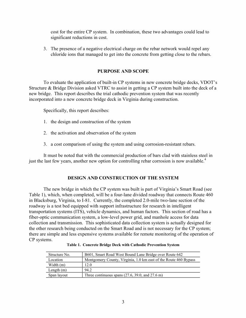
Structure No. B601, Smart Road West Bound Lane Bridge over Route 642 Location Montgomery County, Virginia, 1.0 km east of the Route 460 Bypass Width (m) 12.0 Length (m) 94.2 Span layout Three continuous spans (27.6, 39.0, and 27.6 m)

4
There are basically two methods of applying CP or cathodic prevention. One method, the galvanic method, involves embedding a suitable galvanic anode in the concrete. This anode must have a sufficient natural difference of potential with respect to the reinforcing carbon steel bars to be protected so that when connected, this material would sacrificially corrode and provide sufficient galvanic current to protect the steel bars. Materials such as magnesium, zinc, and some aluminum alloys are relatively more anodic than mild steel and have the potential for serving this purpose.5 However, the relatively high electrical resistivity of concrete has been a major hurdle in developing any of these materials to a stage where it is capable of providing adequate protection to steel bars in a concrete structure on a long-term basis.
The second method of CP, the impressed-current method, uses an external DC power source to energize a suitable anode. In this type of system, the anode and the reinforcing steel to be protected are connected to the positive terminal and the negative terminal, respectively, of the DC power source, which is typically a rectifier. The anode must be made of a material that can sustain current discharge with very little consumption. The anode found to be most suitable for existing concrete decks is an expanded titanium mesh coated with a precious metal-oxide catalyst.6 Although this method has its disadvantages, as shall be discussed later, it was chosen for this trial installation mainly because it can provide controlled and adequate prevention current to the reinforcing bars. From the standpoint of the design for impressed-current protection systems, the type and layout of the anodes are the major differences between a system to be retrofitted into an existing concrete deck, typically during its rehabilitation, and a system for a new deck. For existing concrete decks, an anode mesh is laid over the scarified surface of the entire existing concrete deck after all damaged concrete has been repaired and is then covered with a concrete overlay (Figure 2). The anode mesh typically measures 1.1 to 1.2 m (3.7 to 4.0 ft) wide and 2.4 to 81.0 m at intervals of 320 mm (12.6 in), as proposed by Corrpro Companies, Inc., was used (see Table 2). The titanium mesh ribbons were fastened with special plastic clips over the longitudinal bars once all the rebars for the new deck were in place, as illustrated in Figures 3 and 4. The plastic clips kept the mesh ribbon anodes at least 12 mm (0.5 in) off the longitudinal bars to prevent a short circuit. The spacing of the anode ribbon mesh was to allow for placement and consolidation of the fresh concrete and reasonable distribution of protection current over the entire deck once the system is energized. Figure 5 shows an area in the deck with some of the ribbon mesh already installed securely over the longitudinal bars and a common current distribution connector welded to each ribbon mesh. For redundancy, two common current distribution connectors, which ran longitudinally, were provided in each span to carry the current from a rectifier (see plan in Appendix A). The 94.2-m (309.0-ft) deck, including the parapets, was divided into five separately controlled cathodic prevention zones, which corresponded to the five sections into which the deck was divided for concrete placement (see Appendix A). Figure 6 shows the placement of the concrete after all the components of the cathodic prevention system were in place. The contractor’s personnel took special care to avoid stepping on the anode ribbon mesh or damaging it with the concrete vibrators during placement. Before and during placement, it was essential to make sure that none of the anode ribbon mesh was in contact with any the steel bar, which would

5
Figure 2. Typical Layout of Anode in Impressed-Current CP System for Rehabilitating Concrete Decks. The anode mesh is laid over the scarified surface of the deck and above both mats of reinforcing bars before a new riding surface is placed.
Table 2. Cathodic Prevention System for Smart Road Bridge
Total concrete area protected 1,335 m2 (14,370 ft2) Number of CP zones 5 (18.0, 17.2, 23.8, 17.2, and 18.0 m) Anode ribbon mesh Width 1.3 cm (0.5 in) Composition Titanium, Grade 1 (ASTM B265) Catalyst coating Mixed-metal oxide Current rating 3.5 mA/m (ElgardTM 100) Resistance (Lengthwise) 0.39 ohm/m Modulus of elasticity 105 GPa Tensile strength 245 MPa Yield strength 175 MPa Elongation 24% minimum Maximum spacing (transversely) 32.0 cm (13 in) Current distributor bars Composition Titanium, Grade 1 (ASTM B265) For ribbon mesh in the deck 2 per zone For ribbon mesh in the parapets 2 per zone Rectifier Number of independent circuits 5 Output DC capacity per circuit 5 Amp at 12 V

6
Figure 3. Anode Ribbon Mesh Secured on Longitudinal Bar With Plastic Rebar Clip and Tie (not to scale)
Figure 4. Layout of Anode Ribbon Mesh and Current Distributor Bars. Each distributor connector is welded to every crossing ribbon mesh.
7
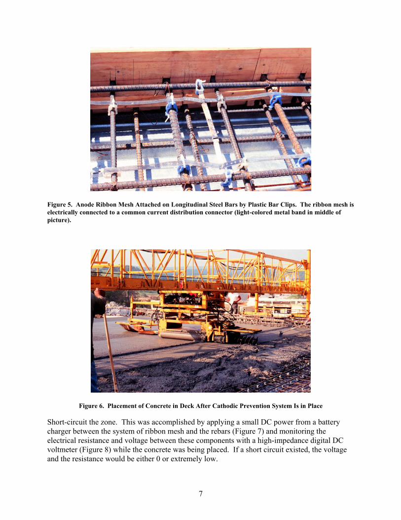
Figure 5. Anode Ribbon Mesh Attached on Longitudinal Steel Bars by Plastic Bar Clips. The ribbon mesh is electrically connected to a common current distribution connector (light-colored metal band in middle of picture).
Figure 6. Placement of Concrete in Deck After Cathodic Prevention System Is in Place
Short-circuit the zone. This was accomplished by applying a small DC power from a battery charger between the system of ribbon mesh and the rebars (Figure 7) and monitoring the electrical resistance and voltage between these components with a high-impedance digital DC voltmeter (Figure 8) while the concrete was being placed. If a short circuit existed, the voltage and the resistance would be either 0 or extremely low.

8
Figure 7. Applying Small DC Voltage Between System of Ribbon Mesh and Rebars at One End of Span or Zone While Concrete Is Placed, Starting From Other End of Span
Figure 8. DC Voltage and Resistance Between Ribbon Mesh and Rebars in Span Monitored With Digital Voltmeter While Concrete Is Placed
Table 3 shows the mean voltages and resistances between the system of ribbon mesh and the rebars in each zone from the beginning until the completion of concrete placement. The readings indicated there was no short circuit in any zone. Figure 9 shows the completed bridge deck.

9
Table 3. DC Voltage and Resistance Between Anode and Rebars in Each Zone During Placement of Concrete in Deck
Concrete Placement
Zone Areaa (m2)
Date From To
Mean Voltage (v)
Mean Resistance (Ω)
1 252 06/03/98 08:00 10:55 0.449 2.20 2 242 06/05/98 11:00 13:30 0.351 1.45 3 347 06/09/98 06:00 08:30 0.199 1.40 4 242 06/10/98 06:15 08:30 0.188 1.30 5 252 06/02/98 06:25 10:36 0.504 2.53
aIncluding parapet walls.
Figure 9. Completed WBL Smart Road Bridge With Built-In Cathodic System
To provide DC power to the system, a simple manual voltage-controlled tap-switch
rectifier with five independent circuits was used (Figure 10). The rectifier was interfaced with the fiber-optic system, through a fiber modem, to allow the DC voltage and current and the rebar potential in each zone to be read from the control center of the Smart Road. A corrosion rate probe was embedded in each zone to facilitate measurement of the response of the steel reinforcement. Other details are available in the special provisions used for the construction of the system, which are provided in Appendix B.

10
Figure 10. Rectifier That Provides Controlled DC to Polarize Steel Bars Cathodically. Notice the five identical sets of circuitry, one for each of the five zones in the bridge deck.
ACTIVATION AND OBSERVATION OF THE SYSTEM
Activation of the System Delays in the construction of the electrical system in the Smart Road prevented the CP system from being energized for more than 1 year after the new deck was completed. Prior to energizing the system, Corrpro Companies, Inc., made a visual inspection of the various wiring connections and the rectifier. In addition, a series of measurements were taken. These included the potentials and the AC resistances between various components, some of which (especially those between the Ag/AgCl reference cells and their ground) are useful indicators of the condition of these components and, for future reference, the initial corrosion rate of the rebars. As Tables 4 and 5 show, the potentials between the lead wires for the reference cells and their ground ranged from –54 to –78 mV, and the AC resistances ranged from 2,500 to 8,300 Ω. These readings were well within the normal potential range of –700 to +100 mV and an AC resistance of less than 10,000 expected from properly installed reference cells.7 For future reference, the corrosion rate of the rebar adjacent to each of the embedded probes was also measured, as shown in Table 6. These rates ranged from 0.001 to 0.026 mm/yr, which were indicative of passive state.

11
Table 4. Potentials Between Various Components Prior to System Being Energized
Potential (mV) Between Components in Pair of Components Zone 1 Zone 2 Zone 3 Zone 4 Zone 5
Reference cell and reference cell ground –77 –61 –58 –54 –78 Counter electrode and reference cell ground
183 207 202 200 184
Reference cell and counter electrode –237 –293 –300 –283 NR Reference cell ground and system ground 0.1 0.2 0.3 0.3 0.3 Anode and system ground 0.1 0.2 0.1 0.2 0.2
Table 5. AC Resistances Between Various Components Prior to System Being Energized
AC Resistance (Ω) Between Components in Pair of Components Zone 1 Zone 2 Zone 3 Zone 4 Zone 5
Reference cell and reference cell ground 2,500 8,000 6,400 8,300 6,200 Counter electrode and reference cell ground
1,500 5,800 2,500 5,300 5,500
Reference cell and counter electrode 3,500 12,000 15,000 12,000 15,000 Reference cell ground and system ground 0.6 1.6 1.5 2.5 2.4 Anode and system ground 0.6 0.6 0.6 0.8 0.7
Table 6. Initial Corrosion Rates of Rebars Adjacent to Embedded Probe in Each Zone
Zone Corrosion Rate (mm/yr) 1 0.001 2 0.026 3 0.024 4 0.006 5 0.003
Mean 0.012 Std. Dev. 0.012
With these normal readings and the visual inspection revealing nothing out of the
ordinary, the CP system was energized on January 6, 2000. The initial settings on the rectifier for the various zones are listed in Table 7. From the circuit voltages and the resulting current going into each zone, the effective circuit resistance for the zone can be estimated. Interestingly, the effective circuit resistances of the five zones, which are a function of the spacing of the anode ribbon mesh, rebar density, resistivity of the concrete, etc., were very low, ranging from only 0.52 to 0.91 ohm, or in terms of unit concrete area, 2.02 to 3.75 mΩ/m2 of concrete area.
Table 7. Initial Settings in Rectifier (January 5-6, 2000)
Setting Zone 1 Zone 2 Zone 3 Zone 4 Zone 5 Voltage (V) 1.38 1.38 1.40 2.38 1.72 Current (A) 1.77 2.67 2.00 2.62 2.36 (mA/m2) 7.02 11.03 5.76 10.83 9.37

12
Circuit resistance (Ω) 0.78 0.52 0.70 0.91 0.73 Circuit resistivity (mΩ/m2) 3.09 2.14 2.02 3.75 2.89
Observation of the System After approximately 16 months of operation, the system was revisited and readings were taken again. The readings, shown in Tables 8 and 9, indicated that (1) the circuit for Zone 1 might not be operating properly or adequately; (2) the AC resistance between the reference cell in Zone 2 and its corresponding ground was higher than the expected range, indicating that this reference cell would have to be watched; and (3) the extent of polarization of the steel bars achieved in the various zones may be insufficient. The corrosion rates of the rebars near the five embedded probes were also measured and were very, very low, ranging from 0.005 to 0.013 mm/yr, with a mean of 0.008 mm/yr (see Table 10). This represents a 33 percent reduction from the initial readings measured in January 2000.
Since it is desirable to have greater polarization of the rebars, the voltage settings on the rectifier were readjusted higher by adjustments of the coarse and fine tap settings. Table 11 lists the new power settings. These settings combined to be approximately 32.05 watts, which is slightly higher than the wattage of a 30-watt light bulb. This time, the estimated effective resistances of the various circuits ranged from 1.75 to 3.64 mΩ/m2 of concrete area, which were not very different from those (2.02 to 3.77 mΩ/m2) approximately 16 months earlier.
Table 8. Rectifier Readings Taken on May 17, 2001
Reading Zone 1 Zone 2 Zone 3 Zone 4 Zone 5
Voltage (V) 0.95 1.59 1.45 1.35 1.75 Current (A) 0.10 1.60 2.16 1.45 2.47 “On” potential (mV)a –149 –213 –167 –153 –141 4-hour depolarization (mV) 0 71 45 46 52
aThe potential of the steel bars while the power was on.
Table 9. AC Resistances Between Various Components AC Resistance (Ω) Between Components in
Pair of Components Zone 1 Zone 2 Zone 3 Zone 4 Zone 5 Reference cell and reference cell ground 10,100 12,400 3,200 2,600 3,000 Reference cell ground and system ground 0.4 1.5 1.4 2.4 2.3 Anode and system ground 0.2 0.6 0.5 0.7 0.6
Table 10. Corrosion Rates of Rebars Adjacent to Embedded Probe in Each Zone (May 2001)
Zone Corrosion Rate (mm/yr)
1 0.006 2 0.012 3 0.006 4 0.013 5 0.005
13
Mean 0.008 Std. Dev. 0.004
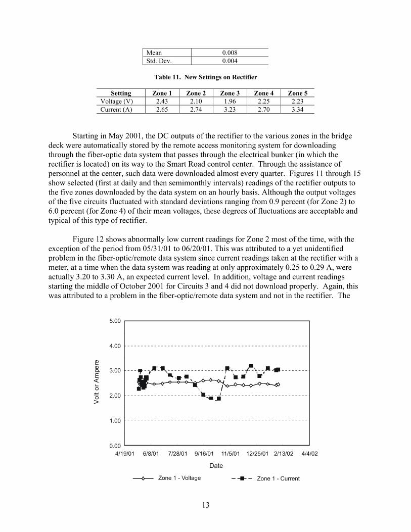
Table 11. New Settings on Rectifier
Setting Zone 1 Zone 2 Zone 3 Zone 4 Zone 5
Voltage (V) 2.43 2.10 1.96 2.25 2.23 Current (A) 2.65 2.74 3.23 2.70 3.34
Starting in May 2001, the DC outputs of the rectifier to the various zones in the bridge deck were automatically stored by the remote access monitoring system for downloading through the fiber-optic data system that passes through the electrical bunker (in which the rectifier is located) on its way to the Smart Road control center. Through the assistance of personnel at the center, such data were downloaded almost every quarter. Figures 11 through 15 show selected (first at daily and then semimonthly intervals) readings of the rectifier outputs to the five zones downloaded by the data system on an hourly basis. Although the output voltages of the five circuits fluctuated with standard deviations ranging from 0.9 percent (for Zone 2) to 6.0 percent (for Zone 4) of their mean voltages, these degrees of fluctuations are acceptable and typical of this type of rectifier.
Figure 12 shows abnormally low current readings for Zone 2 most of the time, with the exception of the period from 05/31/01 to 06/20/01. This was attributed to a yet unidentified problem in the fiber-optic/remote data system since current readings taken at the rectifier with a meter, at a time when the data system was reading at only approximately 0.25 to 0.29 A, were actually 3.20 to 3.30 A, an expected current level. In addition, voltage and current readings starting the middle of October 2001 for Circuits 3 and 4 did not download properly. Again, this was attributed to a problem in the fiber-optic/remote data system and not in the rectifier. The

14
Figure 11. Daily (05/17/01-05/31/01) and Semimonthly Readings of Voltage and Current Polarizing Zone 1 as Recorded by Fiber-Optic/Remote Data System.
Figure 12. Daily (05/17/01-05/31/01) and Semimonthly Readings of Voltage and Current Polarizing Zone 2. The irregularity in the readings was attributed to an improper reading by the fiber-optic/remote data system.

15
Figure 13. Daily (05/17/01-05/31/01) and Semimonthly Readings of Voltage and Current Polarizing Zone 3.
Figure 14. Daily (05/17/01-05/31/01) and Semimonthly Readings of Voltage and Current Polarizing Zone 4
Figure 15. Daily (05/17/01-05/31/01) and Semimonthly Readings of Voltage and Current Polarizing Zone 5

16
fiber-optic data communication system is not essential to any CP system and, as mentioned earlier, was not an intended part of this CP system. In fact, an unwritten valuable advice drawn from the collective experience of state departments of transportation that have tried CP systems is: “Stay Simple.”
COST COMPARISON OF USING A BUILT-IN CATHODIC PREVENTION SYSTEM AND USING CORROSION-RESISTANT REBARS
CP has been a highly effective means of preventing corrosion on a variety of above-ground, underground, and underwater steel structures, and there is no technical reason why it would not be as effective in preventing corrosion of reinforcing steel in new concrete bridges. However, another important issue that must be considered in controlling corrosion in concrete bridges is its cost. The costs of available corrosion control options (in this case, the use of a CP system built into a new concrete deck or the use of a corrosion-resistant rebar) are different. Currently, there are two types of highly corrosion-resistant rebars that can be used: (1) bars made entirely of a stainless steel, such as austenitic 304, 316, duplex 2205, etc., and (2) new bars made of a carbon steel core clad with a layer of a stainless steel, which can be 304, 316, etc.
Table 12 shows the initial costs of a built-in CP system, stainless steel– clad bars, and solid stainless steel bars. The cost of $7/ft2 for a CP system, which was actually the quoted price for the current project, can be considered representative. It is just slightly higher than the cost of using clad bars, which is the cheapest among the three options. The cost of a CP system is attributable to engineering, materials, and labor costs. The labor cost is buoyed by the time-consuming installation of the ribbon mesh, which has to be securely fastened to each bar (in this design, the longitudinal bars) it comes across and then spot-welded to two current distributor connectors. In contrast, the use of either the clad bar or one of the solid stainless steel bars entails only a higher material cost, with the same installation labor cost as with conventional carbon steel bars.
The life-cycle cost of a concrete deck with each of these three options can be estimated
from the initial construction costs of each system or material (Table 12) and the discounted future repair costs over an assumed life of 75 years for a hypothetical concrete bridge deck in an urban area with the “typical” salt exposure environment of Roanoke, Virginia. Table 13 shows the different parameters that can be used to estimate the life-cycle costs of the options. The operation and maintenance of a CP system require utility services (electricity and a telephone line, the latter for monitoring the system remotely), a monthly (at least) check of the rectifier readings, site visitations for replacement of minor electrical components, and replacement of the rectifier approximately every 20 years.
Table 12. Initial Costs Associated With New Options for Preventing Corrosion of Reinforcement in New Concrete Bridges
Initial Cost of Option
Option $/lb $/ft2 Use of carbon steel bars and CP NA 7.00a Use of clad carbon steel bars 1.20 6.24b Use of stainless steel 316 bars 2.25 11.70b

17
aExcluding the cost of installed carbon steel bars. bNot including installation cost.
18
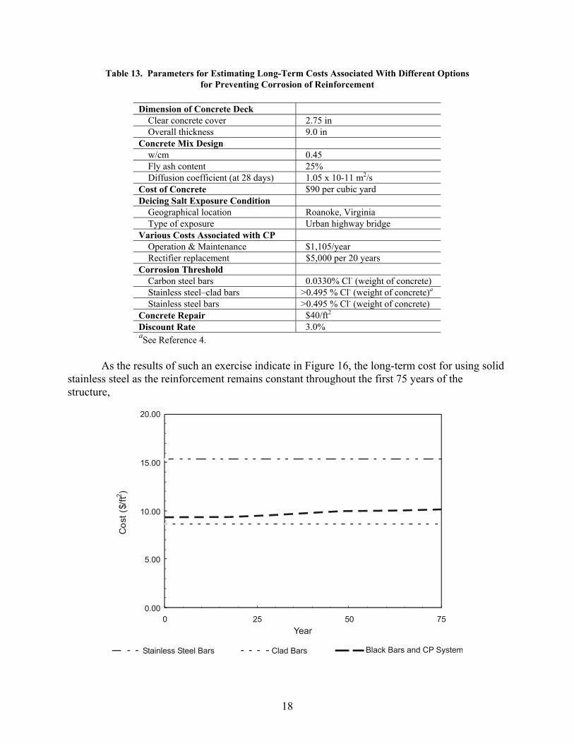
Table 13. Parameters for Estimating Long-Term Costs Associated With Different Options for Preventing Corrosion of Reinforcement
Dimension of Concrete Deck Clear concrete cover 2.75 in Overall thickness 9.0 in Concrete Mix Design w/cm 0.45 Fly ash content 25% Diffusion coefficient (at 28 days) 1.05 x 10⁻¹¹ m2/s Cost of Concrete $90 per cubic yard Deicing Salt Exposure Condition Geographical location Roanoke, Virginia Type of exposure Urban highway bridge Various Costs Associated with CP Operation & Maintenance $1,105/year Rectifier replacement $5,000 per 20 years Corrosion Threshold Carbon steel bars 0.0330% Cl- (weight of concrete) Stainless steel–clad bars >0.495 % Cl- (weight of concrete)a Stainless steel bars >0.495 % Cl- (weight of concrete) Concrete Repair $40/ft2 Discount Rate 3.0%
aSee Reference 4.
As the results of such an exercise indicate in Figure 16, the long-term cost for using solid stainless steel as the reinforcement remains constant throughout the first 75 years of the structure,

19
Figure 16. Present Value of Cumulative Costs of Concrete Bridge Deck Using Various Options to Prevent Corrosion of Reinforcement. Costs include materials, including concrete, and labor. at approximately 30 percent more than the cost for using a CP system or clad bars. The long-term cost for incorporating CP appears to be the middle among the three options: slightly higher than that associated with the use of clad bars. The use of clad bars appeared to cost the least, even from the very beginning of the life of the structure. As with the cost of using solid stainless steel bars, it remains constant throughout the first 75 years because of their high chloride resistances.4 Based on current market prices, using stainless steel 304 would cost as much as using stainless steel 316; however, using duplex stainless steel 2205 could cost 25 percent less than these options because the higher strength of this stainless steel would allow the use of correspondingly fewer bars.
Perhaps the most practical hurdle for the CP option is that it requires a commitment of resources, especially time, on the part of bridge personnel to inspect and maintain the systems regularly once constructed; each system is effective only if it is maintained. In time, electrical connections between different wirings and components can come loose, and fuses and diodes in the rectifier can become defective. Even though identifying and fixing such problems are simple, the time required to do them may be difficult to find. Some of these time requirements may be lessened with the use of a remote monitoring system to eliminate the need to visit the site until a problem arises; however, the more sophisticated a system becomes, the more chance that something will go bad. An option that could possibly help reduce the time burden significantly is the use of photovoltaic panels in place of a rectifier to supply the small amount of DC power needed to polarize the steel bars. Such an alternate power source is much simpler than a rectifier and would require less repair. It is even possible that rechargeable batteries would not be needed with such a solar system since some have theorized that polarization of the steel bars may not be necessary all the time to keep them passive. In contrast, once clad or stainless steel bars are in a deck, they will not need to be maintained because their chloride corrosion thresholds are much higher,4 so that reinforcement corrosion would become irrelevant, and perhaps other phenomena would be limiting factors regarding the service life of a concrete bridge within the first 75 or 100 years. For application in existing concrete bridges, the high cost of a CP system and the associated time demands for regular inspection and maintenance of the system may be acceptable, especially in a situation where the structure is heavily used and needs to be kept in operational condition for, say, only 15 to 20 additional years until funds for replacement become available. In such case, other factors such as the need to keep traffic flowing continuously may override the above-mentioned unfavorable aspects of using CP. For such structures, in particular for concrete piers, there are effective anodes available that allow the option of galvanic CP, which eliminates the need for rectifiers.8
CONCLUSION

20
• Even though using an impressed-current CP system in a new concrete bridge deck is a feasible option for preventing the initiation of corrosion on rebars, there are issues concerning its practicality and cost-effectiveness.
RECOMMENDATIONS 1. Unless there is a commitment on the part of bridge owners to maintain impressed-current CP
systems regularly, the use of cathodic prevention should not be considered for a new bridge deck.
2. Other options for preventing or eliminating corrosion in new concrete bridges that are
relatively trouble-free and cost-effective, such as the use of stainless steel–clad bars, should be considered.
ACKNOWLEDGMENTS The authors convey their appreciation to S. Stone of the Virginia Tech Transportation Institute for his valuable assistance in downloading readings from the remote access monitoring system incorporated into the rectifier; likewise to S. F. Daily, M. Funahashi, and M. Islam of Corrpro Companies, Inc., for their assistance. Finally, thanks go to many others, especially personnel from VDOT’s Salem District and the Virginia Transportation Research Council, who have helped in various ways.
REFERENCES 1. Hoppe, E.J., Clemeña, G.G., and Abouseid, O.S. Work Plan: Evaluation of a Heated Bridge
Deck in Virginia. Virginia Transportation Research Council, Charlottesville, 1995. 2. Bazzoni, A., Bazzoni, B., Lazzari, L., Bertolini, L., and Pedeferri, P. Field Application of a
Cathodic Prevention on Reinforced Concrete Structures. Corrosion 96, National Association of Corrosion Engineers International, Houston, Texas, 1996.
3. Daily, S.F., and Kendell, K. Cathodic Protection of New reinforced Concrete Structures in
Aggressive Environments. Materials Performance, Vol. 37, No. 10, pp.19-25, 1998. 4. Clemeña, G.G., and Virmani, Y.P. Testing of Selected Metallic Reinforcing Bars for
Extension of Service Life of Future Concrete Bridges: In Outdoor Concrete Blocks. VTRC-03-R7. Virginia Transportation Research Council, Charlottesville, 2002.
5. American Society for Testing and Materials, Committee G-1. ASTM G 82: Standard Guide
for Development and Use of a Galvanic Series for Predicting Galvanic Corrosion Performance. West Conshohocken, Pennsylvania, 2002.

21
6. Clemeña, G.G., and Jackson, D.R. Cathodic Protection of Concrete Bridge Decks Using Titanium-Mesh Anodes. FHWA/VTRC-00-R14. Virginia Transportation Research Council, Charlottesville, 2000.
7. Bennett, J.E., Bushman, J.B., Clear, K.C., Kamp, R.N., and Swiat, W.J. Cathodic Protection
of Concrete bridges: A Manual of Practice. SHRP-S-372. National Research Council, Washington, D.C., 1993.
8. Virmani, Y.P., and Clemeña, G.G. Corrosion Protection: Concrete Bridges. FHWA-RD-
98-088. Federal Highway Administration, Washington, D.C., 1998.

APPENDIX A
PLAN VIEW OF CATHODIC PREVENTION SYSTEM LAYOUT IN WBL SMART ROAD BRIDGE OVER RT. 642

22

23

24

25

APPENDIX B
SPECIAL PROVISIONS FOR BRIDGE DECK CATHODIC PREVENTION OF CORROSION
(Project: IVHS-060-101-B601)

28
29
I. DESCRIPTION This item involves the installation of a cathodic prevention system for a new concrete deck slab and parapet on the W.B.L. Smart Road over Route 642 in Montgomery County, Virginia. The cathodic prevention system consists of an anode system, rectifier, reference cells, data system, DC wiring, conduit, AC power supply to the rectifier, and all associated electrical connections. The purpose of the system is to prevent the reinforcing steel bars in the deck and the parapet walls from corroding, by passing a low-voltage direct current from the anode to the steel. II. GENERAL DESIGN REQUIREMENTS The bridge deck shall be subdivided into five (5) separately controlled cathodic prevention zones. The zone dimensions shall correspond with the deck slab concrete placement schedule on the plans. The anode ribbon mesh shall be placed in the transverse direction as shown in the plans. Maximum allowable anode current density shall be 110 mA/sq.m. Two current distributors shall run lengthwise for the full length of each zone. Design life of both the anode and the current distributors shall be at least 75 years. To assure uniform current distribution to the bridge deck, the anode IR drop shall not exceed 300 mV from the power feed point to the furthest point from the power feed. Each zone shall also contain one system negative and one reference cell, as shown in the plans. Any embedded steel besides the reinforcing bars (i.e., scuppers, conduits, piping, support bolts, etc.) must be made electrically continuous with, or completely isolated from the cathodic protection system, as determined by the Engineer. The power wiring cables for the anode system and the system ground shall be sized according to the National Electric Code. III. MATERIALS A. ANODE SYSTEM The anode system shall consist of catalyzed titanium ribbon mesh, current distributors, and plastic rebar clips. The specifications for each of these components is given below: Catalyzed Titanium Mesh Ribbon Anode The anode shall consist of Elgard 100 Anode Ribbon Mesh, as supplied by Corrpro Companies, Inc., Medina, Ohio or equivalent. The anode shall have the following properties:
Substrate composition………………….. Titanium, Grade 1 (ASTM B265) Anode coating………………………….. Mixed metal oxide catalyst Width…………………………………… 13 mm Length.………………………………….. 76 m per roll Thickness……………………………….. 0.6 mm Diamond-shaped openings……………… 2.5 mm x 4.6 mm Current rating…………………………… 3.5 mA/m Resistance (lengthwise)………………… 0.39 ohm/m Modulus elasticity………………………. 105 GPa Tensile strength…………………………. 245 MPa

30
Yield strength…………………………… 175 MPa Elongation………………………………. 24% min.
The anode ribbon mesh to be supplied in this project shall have at least two years of proven track record on a reinforced concrete structure in North America. Current Distributor This current distributor shall be a solid Grade 1, 12.7-mm wide uncoated titanium bar. Its thickness shall be 0.9 mm (min). Insulated Titanium Connector This connector shall consist of a titanium rod, 3.175 mm in diameter, 400 mm long, with a 300 mm section of current distributor factory welded to the rod. The current distributor shall overlap the rod by approximately 50 mm, and welded together with spot welds at three locations (min.). The spot welds shall be made at the factory using a high powered resistance welder. The exposed rod shall be insulated with heat shrink tubing for approximately 300 mm, leaving 50 mm uncovered. Plastic Rebar Clips Each rebar clip shall be injection-molded plastic clips suitable for clamping around both No. 5 and No. 4 reinforcing bars, and on which a anode ribbon can be securely attached with a plastic tie. Plastic Ties Plastic ties for securing the anode ribbon to the rebar clips shall be nylon locking cable ties 2.5 mm in width, 99 mm long, and 1.1 mm in thickness. B. RECTIFIER The rectifier shall be a manual voltage control tap-switch rectifier with filtered DC output and silicon diodes. The power supply shall have a non-conductive front panel with a digital panel meter for monitoring the rectifier DC voltage and current for each zone. The rectifier shall have an individual circuit for each anode zone, for a total of five. Each DC output circuit shall be rated at 12 volts at 5 amperes. Variation in the AC input from 5% below to 10% above rated line values shall not damage any components nor alter the rated DC outputs. The rectifier shall have a fuse in each positive output and a quick acting magnetic breaker rated at 120% of the circuit capacity. A relay shall be installed in the AC input to permit interruption of the rectifier by a remote monitoring system. The spare fuses of the same rating shall be provided and secured inside the rectifier enclosure. DC shunts shall be provided for each circuit. The shunts shall be mounted on the front panel of the rectifier. The unit shall be furnished with upgraded lightning arrestors (high joule MOVs) on both the AC and DC sides. Test jacks, suitable for connecting #18 AWG wires, shall be provided to terminate three instrumentation lead wires per zones. The rectifier enclosure shall be air-cooled, NEMA type 3R, 11 gauge, hot-dipped galvanized steel, with a hinged weatherproof door with gasket. All openings shall be screened. The housing door shall be lockable and shall have a bronze padlock and three keys. The front shall have double swing doors hinged in the front corners. The side panels shall also be hinged for easy access. The inside of the front door shall have a tray to hold the maintenance manual.

31
The rectifier shall be equipped with a 120 VAC, Grounded Fault Interrupter (GFI), grounded AC convenience outlet mounted on the panel face. The outlet shall be fused for 15 amperes and be attached to the line side of the circuit breaker. C. REMOTE MONITORING SYSTEM A remote monitoring system shall be provided to monitor the DC voltage and current for each rectifier circuit, including the potential of the reference cell in the corrosion rate probe for each zone. The system shall consist of a remote monitoring unit (RMU), complete with integral telephone modem and user-friendly operating software. The RMU shall be capable of monitoring all rectifier circuits simultaneously. The purpose of the remote monitoring system is to transfer rectifier operating data to a remote computer terminal, thus eliminating routine site inspections. The RMU enclosure shall have a NEMA 4 rating, with hinged cover and gasket. The RMU shall be mounted inside the rectifier enclosure, so that it is easily accessible for maintenance. A surge protector shall be provided. All wirings connecting the RMU with the rectifier shall be insulated #18 AWG communication wires. Cables providing AC power to the RMU shall be designed and installed in accordance with the NEC. Wiring shall be neatly installed within the enclosure using plastic wire ties. The remote monitoring system shall be supplied with an operating and maintenance manual. D. CORROSION RATE PROBE The corrosion rate probe shall be manufactured in accordance with the detail drawings. The probe shall consist of a silver-silver chloride reference cell and a counter electrode. The reference cell shall consist of a silver metal covered in silver chloride electrolyte and encased in a concrete-compatible jacket. The lead wire for the reference cell shall be No. 10 AWG wire with blue-colored HMWPE insulation. The counter electrode shall consist of a 3.175 mm diameter x 76 mm long titanium rod coated with mixed-metal-oxide catalysts. The lead wire for the counter electrode shall be a No. 10 AWG wire with red-colored HMWPE insulation. The reference cell and counter electrode shall be cast in a 100-mm diameter x 175-mm long concrete mortar cylinder with no chloride added. The cylinder shall have two fiberglass rods extending through the cylinder to support the assembly between reinforcing steel bars at the top mat of reinforcing steel. The fiberglass rods shall be 9.5-mm diameter x 300-mm long. E. ELECTRICAL The junction boxes shall be molded PVC and suitably weatherproofed for outdoor installation. The minimum size shall be 203 mm x 203 mm x 102 mm. Stainless steel bolts shall be provided to secure the junction boxes to the soffit of the deck. Anchors shall be encased in a nonmetallic expansion shield and the hole shall be filled with epoxy. A weep hole shall be provided in each junction box. The conduits for the DC circuitry shall be PVC Schedule 80. The conduit shall be sized in accordance with the latest revision of the National Electrical Code (NEC) for wire fill. Conduit shall be mounted securely using suitable nonmetallic hangers or straps, with support spacings of not greater than that indicated by Article 347(8) of NEC. Expansion joints shall be installed in accordance with the manufacturer’s recommendations for temperature change of 38oC (100oF). Weep holes shall be provided at all low points in the conduit run. Stainless steel bolts shall be provided to secure the conduit to the
32
soffit of the deck. Likewise, anchors for the conduit shall be encased in a nonmetallic expansion shield and the hole shall be filled with epoxy. F. WIRING Wiring to be encased in the concrete shall be No. 10 AWG with HMWPE insulation. Power wiring in conduit shall be at least No. 10 AWG with THHN insulation. Instrumentation wiring in conduit shall be No. 18 AWG shielded, twisted pair communication wires with PVC outer jacket. All wiring shall be labeled at the junction box and rectifier to identify its function and location.
G. CONNECTIONS The connections of the working electrode (for the corrosion rate probe) and the system negative to the reinforcing steel shall be made by thermite welding method. All thermite weld connections shall be coated with a 100%-solids, non-conductive epoxy. The connections of system negative and positive in the junction boxes shall require the use of mechanical crimp connection, which is subsequently sealed from the environment with a suitable insulating material. The mechanical and crimp connections shall be Lisco Part No. CT-8, or equivalent. The insulating material shall be heat-shrinkable material such as Alpha FIT-700 or 3M E-Z Seal.
IV. PROCEDURES
A. UTILITIES The Contractor shall install a complete electrical service and dedicated telephone line, with associated equipment and terminations, as indicated on the plans or as directed. AC input for the rectifier shall be 120 or 220 Volts, 60 Hertz, single phase. The service shall have a minimum 30-Amp rating. A fused disconnect switch shall be provided in a separate enclosure. The installation shall be in accordance with the VDOT standard drawings for direct burial cable, and local utility company standards.
B. ANODE SYSTEM The spacing between the titanium mesh ribbon anode and the reinforcing steel in the deck shall be a minimum of 12 mm. The anode shall be securely attached to the longitudinal reinforcing steel bars using plastic rebar clips and tie wires, so that the construction activity associated with the placement of concrete does not cause the anode to shift or come in contact with any part of the structural steel assembly. Sufficient number of 150-mm length sections of PVC pipe shall be provided in the deck for passing the insulated titanium connector, system negative, and instrumentation wiring to the junction box. These pipes shall be 38-mm diameter, schedule 80 PVC heavy wall conduit. The anodes and the current distributors shall be installed in accordance with the manufacturer’s instructions. A general procedure for installing the mesh ribbon anodes is given below: The mesh ribbon anodes and the current distributor bars shall be placed on the deck as shown on the plans. The ribbon anodes shall be cut into sections that match the width of the deck. The first length of ribbon anode shall be installed in the transverse direction at the edge of the anode zone. The ribbons shall be attached to the longitudinal bars in the top mat using plastic rebar clips and cable ties as shown on the drawings. Each longitudinal bar shall have a rebar clip where the mesh ribbon anode passes over. The

33
mesh ribbon anode and rebar clips shall be installed between the transverse bars and shall face upwards. The ribbon mesh shall be tensioned slightly during installation. Additional plastic cable ties may be used to secure the anode in place. Each successive width of mesh ribbon shall be placed adjacent to the last until the entire zone is covered. Care shall be taken to make sure that the anode does not come in contact with the reinforcing steel. The Contractor shall take special precautions to ensure that the anode is not damaged or pushed onto the steel during the concrete placement. During the pour, the concrete shall be directed away from the anode. Care shall be taken to ensure that vibrators do not come into contact with the anode. Non-metallic spacers shall be used to prevent the current distributor from contacting the reinforcing steel. After all of the ribbon anodes and the current distributors have been installed, additional clips shall be installed as directed by the Manufacturer’s technical representative. The ribbon mesh shall be fastened sufficiently to prevent significant movement during placement of the concrete. Two lengths of mesh ribbon anodes shall be installed in the longitudinal direction inside each parapet wall, as shown on the drawings. The ribbon anodes shall terminate at 160 mm before each zone boundary. The ribbon shall be connected to the main anode grid using two “T” extensions that are made of current distributor bars, as shown on the drawings. All titanium-to-titanium connections shall be metallurgical bonds made by resistance welding with equipment supplied by the anode manufacturer and used in accordance with the manufacturer’s instructions. Prior to commencing welding, the equipment settings shall be tested by welding current distributor test strips, to ensure that satisfactory welds will be obtained.
C. CORROSION RATE PROBE The corrosion rate probes shall be installed as indicated on the plans and as directed by the technical representatives of Cathodic Protection. One corrosion rate probe shall be installed in each anode zone. The probes shall be cradled on two fiberglass rods securely attached to two reinforcing bars in the top mat with plastic cable ties (see plans). The corrosion rate probe wires and working electrode cables shall pass through the PVC conduit access hole to the junction box.
D. REBAR GROUND CONNECTIONS The system negative and working electrode cables shall be connected to the reinforcing steel by the thermite welding method. Approximately 12 mm of insulation shall be removed from the end of the wire. The steel surface shall be wire brushed to remove any material that could interfere with the establishment of a good bond. The batting is placed over the cleaned area and the sleeved wire located in the hollow. The mold is placed over the hollow such that 3 mm of the wire is exposed. The thermite charge is located and ignited. The thermite charge used shall be an Erico CA-25 or equivalent. All thermite weld connections shall be coated with a 100% solids non-conductive epoxy. The system negative and working electrode cables shall pass through the PVC conduit access hole to the junction box.
E. CURRENT DISTRIBUTORS
34
The current distributors shall be installed below the transverse bars in the top mat using an inverted plastic rebar clips and cable ties. To obtain a desired length of current distributor, or to make splices between strips, the strips can be resistance welded together. Splicing shall be made by overlapping the ends of two strips by approximately 75 mm and then spot welding at every 12 mm. If the resulting length is longer than required, the current distributor can be cut to fit with tin snips. A factory fabricated anode connector with 3.175 mm diameter titanium rod may be installed on the deck to facilitate connection between the current distributor and positive anode cable in the junction box. Two anode connectors shall be installed in each zone as indicated on the plans. The anode lead connector is spot welded to the titanium rod in the factory, and then spot welded to the current distributor in the field. At least six spot welds shall be provided between the anode connector and the current distributor. Once the titanium rods, system negative and instrumentation wires are inserted through the PVC access hole conduit, the conduit shall be filled with a non-conductive, waterproofing material, such as acrylic latex caulking. The current distributor shall terminate approximately 160 mm before each zone boundary.
F. RECTIFIER The rectifier shall be installed at Junction Bunker Station #106+65. Galvanized steel anchor bolts, inserts and washers shall be used to secure the enclosure to the concrete floor inside the junction bunker. Grounding rods and cable shall be sized and installed such that the power supply to ground resistance is less than 25 ohms. Tests shall be conducted to verify this criterion.
V. TESTING REQUIREMENTS The following tests shall be performed by the technical representatives of Cathodic Protection:
A. ANODE STEEL ISOLATION CHECK After the anode has been installed in each zone, a check shall be made to ensure that the anode is discontinuous from the steel so that the cathodic protection system will function as intended. Isolation checks shall be made prior to, during, and after the concrete pour. Testing shall be conducted using a digital multimeter and an AC resistance meter. Suggested meters include a Fluke Model 85 multimeter and a Nilsson Model 400 AC resistance meter. Prior to taking the readings, the surface of the steel bar that is an intended contact point of the meter with the steel mat must be cleaned to a bright metal condition at each test location, or a rebar ground connection may be used in that zone. The connection to the anode may be made at any convenient location. Prior to the concrete pour, the millivolt drop between the anode and steel shall be measured. A wet sponge shall be used as an electrolyte between a portion of the anode and the reinforcing steel in each zone. Readings of 1 mV or less are indicative of a short circuit and the contact must be located and cleared. The millivolt drop between the anode and steel shall be measured continuously during the concrete pour for each zone. A log shall be maintained showing the millivolt readings as a function of time. If the voltage drops to zero immediately, then a short has occurred. Alternatively, a small DC power supply may be used to energize the anode during the pour. The potential of a portable reference cell placed in the wet concrete or the embedded cell in the corrosion rate probe may be used to monitor the steel potential with current “on” and current “off”. If the potential shifts more negative when the current is
35
turned “off”, then a short has occurred and the contact must be cleared before the concrete pour can proceed. After the concrete pour has been completed, the DC voltage and AC resistance shall be measured between the anode and steel. The results of this testing will be dependant on the size of the zone, as well as other variables.
B. ENERGIZATION TEST Initial measurements prior to energization shall consist of electrical continuity testing between all rebar ground connections at the rectifier, the static potential and AC resistance of the embedded reference cells, and the open circuit potential and AC resistance between the anode and steel. Additionally, the technical representatives of Cathodic Protection shall obtain corrosion rate probe measurements prior to energizing the cathodic protection system and immediately after the system is energized. The equipment necessary to perform the corrosion rate testing will be provided by the Virginia Transportation Research Council. After the initial system measurements are obtained, the system shall be energized. The potential of the steel is monitored by using the embedded reference cell in the corrosion rate probe. The criterion for adequate current shall be a depolarization of at least 100 mV after a minimum of 4 hours. This test shall be made by measuring the steel potential immediately after the current is turned off and monitoring the change in the potential with time. If the depolarization is less than 100 mV, then the voltage setting on the power supply must be increased. The results of the initial measurements and depolarization testing shall be submitted in writing. VI. DOCUMENTATION AND TRAINING An operating and maintenance manual shall be submitted for the entire system. The manual shall document the results of all tests performed on the project and shall include “as-built” drawings. Three manuals shall be provided. The technical representatives of Cathodic Protection shall provide training to the owner’s personnel regarding the operation and maintenance of the system.

![GAIL INDIA LIMITED CONSTRUCTION OF STEEL PIPELINE AND ... - CATHODIC PROTECTION_14.pdf · 3.1 Temporary Cathodic Protection [TCP]: Using sacrificial [Mg or Zn] anodes pre-packed in](https://static.fdocuments.in/doc/165x107/5dd12376d6be591ccb646812/gail-india-limited-construction-of-steel-pipeline-and-cathodic-protection14pdf.jpg)


![DNVGL-RP-F103 Cathodic protection of submarine … Final anode sizing and distribution of anodes (see [6.7]) ... Cathodic protection of pipelines can be achieved using galvanic (also](https://static.fdocuments.in/doc/165x107/5ae4bbc97f8b9a29048b496f/dnvgl-rp-f103-cathodic-protection-of-submarine-final-anode-sizing-and-distribution.jpg)