Final Remedy Work Plan Ft. Smith,...
28
Transcript of Final Remedy Work Plan Ft. Smith,...


Final Remedy Work Plan Ft. Smith, Arkansas
Prepared for: Whirlpool Corporation
Benton Harbor, MI
Prepared by: ENVIRON International Corporation
Little Rock, Arkansas
Date: February 24, 2014

Contents ii ENVIRON
Contents Page
1. Introduction 1 1.1 Background 1 1.1.1 General Site Description 1 1.1.2 Facility Operations 1 1.1.3 Previous Site Investigations 2 1.1.4 Historical Bench Scale and Pilot Studies 2 1.1.5 Conceptual Site Model 3 1.2 Human Health Risk Assessment Summary 4 1.3 Remedy Objectives 5 1.4 Remedy Technical Approach 5
2 Remedy Implementation 5 2.1 Institutional Controls 6 2.2 Impermeable Soil Cover 6 2.3 In-Situ Chemical Oxidation 6 2.3.1 Pre-Design 7 2.3.2 Bench Scale Testing 8 2.3.3 Adaptive Remedy Implementation 8 2.4 Monitored Natural Attenuation 9 2.5 Soil Vapor Monitoring 9 2.6 Groundwater Monitoring 10
3 Performance Monitoring 10 3.1.1 Quarterly Performance Monitoring 10 3.1.2 Annual Progress Reports 11 3.1.3 Two Year Review 11 3.1.4 Alternative Remedy Plan 11 3.1.5 Five Year Review 11 3.2 Contingency Plan 11
4 Schedule 12

Contents iii ENVIRON
List of Figures
Figure 1: Site Location Map Figure 2: Site Layout Map Figure 3: Groundwater Treatment Areas and Fall 2013 Groundwater Results Figure 4: Pre-Design Data Acquisition Membrane Interface Probe Locations Figure 5: Pre-Design Testing Locations – Area 1 Figure 6: Pre-Design Testing Locations – Areas 2 and 3 Figure 7: Soil Gas Locations Figure 8: Typical Nested Soil Gas Monitoring Point Construction Details Figure 9: Final Remedy Work Plan Schedule

Contents iv ENVIRON
Acronyms and Abbreviations ADEQ: Arkansas Department of Environmental Quality
cis-1,2-DCE: cis-1,2-dichloroethylene
COC: constituent of concern
CSM: conceptual site model
1,1-DCE: 1,1-dichloroethylene
EC: Electrical Conductivity
HHRA: human health risk assessment
HPT: hydraulic profiling tool
ISCO: in-situ chemical oxidation
ITMW: International Technology monitoring well
MCL: Maximum Contaminant Level
MIP: membrane interface probe
MNA: monitored natural attenuation
MW: monitoring well
PCE: tetrachloroethylene
RADD: Remedial Action Decision Document
RAL: remedial action level
RRMP: Revised Risk Management Plan
1,1,1 - TCA: 1,1,1,-Trichloroethane
TCE: trichloroethylene
trans-1,2-DCE: trans- 1,2-dichloroethylene
UST: underground storage tank
USEPA: United States Environmental Protection Agency
Work Plan Final Remedy Work Plan
Final Remedy Work Plan
1 ENVIRON
1. Introduction In accordance with the Remedial Action Decision Document (RADD) issued by Arkansas Department of Environmental Quality (ADEQ) on December 27, 2013, ENVIRON on behalf of Whirlpool Corporation is submitting this Revised Final Remedy Work Plan (Work Plan). The purpose of the Work Plan is to outline relevant elements to implement the final remedy defined by the RADD. This Work Plan provides details on the activities and schedule for implementation of the final remedy for the Whirlpool Site.
The RADD provides the basis for ADEQ’s final remedy selection, including a summary of activities already completed at the site. This Work Plan presents the plan to meet the requirements of the RADD, and is not intended to restate or summarize the RADD. The Work Plan is complimentary to the Revised Risk Management Plan dated May 21, 2013 and the Revised Risk Management Plan Addendum dated June 14, 2013 (hereinafter collectively referred to as the RRMP). The Work Plan will reference relevant sections of the RRMP where appropriate.
1.1 Background The following is a summary of the site background. For additional detail refer to Section 1.1 of the RRMP.
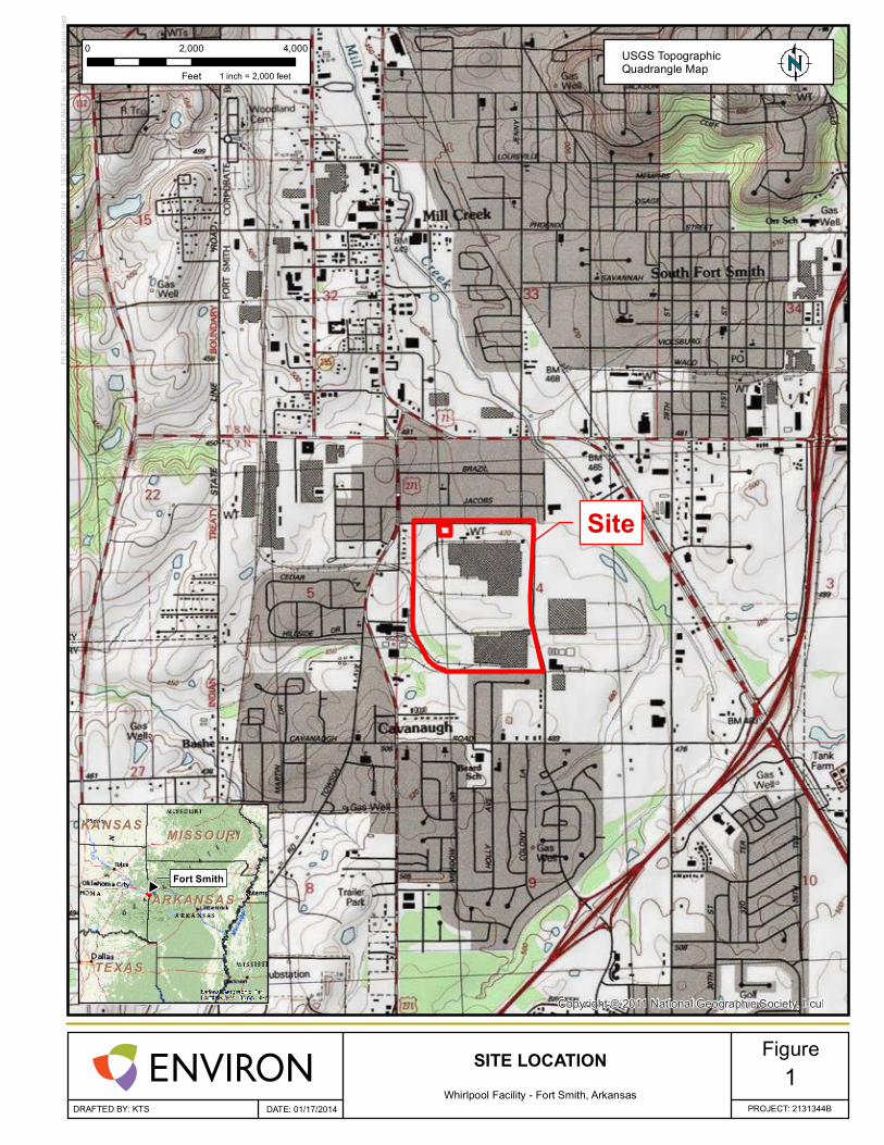
1.1.1 General Site Description The Whirlpool Fort Smith facility is located at 6400 Jenny Lind Road on the south side of Fort Smith, Arkansas (Figure 1) and is currently inactive. The entire facility is approximately 153 acres and includes the main manufacturing building (approximately 1.3 million square feet), separate warehouse and administrative offices, and approximately 21 acres of undeveloped land (Figure 2). Additional buildings located on the north side of the property include a water treatment plant and boiler house. The majority of the property surrounding the buildings is covered with concrete or asphalt service roads and parking. Some gravel parking areas are also present.
1.1.2 Facility Operations Historical manufacturing processes at the Whirlpool Fort Smith facility involved metal fabrication, plastic thermoforming and assembly operations. Constituents in the soil and groundwater identified during facility investigations are the result of historical practices.
Dating back to approximately 1967, equipment degreasing operations utilizing trichloroethylene (TCE) were performed in the former degreaser building located near the northwestern corner of the main manufacturing building and west of the boiler house (Figure 2). The degreasing equipment consisted of a tank and parts rack. The degreasing operations involved placing parts into the parts rack positioned over the tank. The TCE tank was then heated, creating a TCE vapor in the area where the parts were placed. Following degreasing activities, the vapor was condensed and returned to the tank below the parts rack.
The use of TCE in the degreasing operations ceased after TCE was classified as a hazardous waste and the TCE degreasing process was addressed in hazardous waste regulations

Final Remedy Work Plan
2 ENVIRON
promulgated in 1980. 1,1,1,-Trichloroethane (1,1,1-TCA) replaced the use of TCE until the degreaser operation stopped altogether in 1989. No historical records that document any TCE spills or release incidents from the degreaser building have been located.
1.1.3 Previous Site Investigations A series of soil and groundwater studies were initiated at the site as part of a project to remove one underground storage tank (UST) previously containing fuel. The UST closure certification analytical data indicated the presence of TCE and other solvents in the shallow groundwater. Subsequent investigations have been completed to refine soil and groundwater impacts above the maximum contaminant levels [MCLs] from United States Environmental Protection Agency [USEPA]) to the east, south or west of the Whirlpool facility property boundaries. Based on previous investigations it was determined the primary constituent of concern (COC) is TCE. Tetrachloroethylene (PCE) and TCE daughter products (including cis-1,2-dichloroethylene (cis-1,2-DCE), trans- 1,2-dichloroethylene (trans-1,2-DCE), 1,1-dichloroethylene (1,1-DCE), and vinyl chloride) have also been periodically detected in monitoring wells above drinking water criteria.
1.1.4 Historical Bench Scale and Pilot Studies In 2000, a bench scale treatability study was completed to investigate the effectiveness of permanganate for treating chlorinated compounds in site-specific soils. Soil samples were collected from groundwater monitoring well MW-25, and used for the study. In this study, TCE was detected at a concentration of 100,000 ug/L, which was representative of site conditions. Testing was then completed to determine the total permanganate demand as well as to verify that the permanganate oxidant could destroy the TCE in the site-specific sample. The bench scale study results indicated that permanganate was able to reduce TCE concentrations in the representative soil sample by almost 100%. A total potassium permanganate demand of 1 to 2.5 g/kg wet weight soils was identified; however, it was noted that the concentration of permanganate would most likely need to be increased in the field.
An on-site pilot scale test was conducted in 2002 to evaluate the use of permanganate for full scale treatment at the site based on the results of the bench scale evaluations. This test was conducted in the transmissive gravel zone on-site. The soil oxidant demand used for oxidant calculations during this test was less than the oxidant demand identified during the bench scale study, therefore, less than the suggested amount of oxidant was applied during the field scale test. The results indicated that in-situ chemical oxidation (ISCO) was effective in treating the COCs within the treatment zone and over 20 feet outside the treatment zone in the transmissive gravel portion. After the test was completed, COC concentrations rebounded to pre-test levels as a result of the placement of the test area being too far from the plume. Back diffusion occurred due to the flow direction from areas of higher TCE concentrations through the test location.
Permanganate was also evaluated in off-site interim measure activities in April and June of 2009. The objective of this interim measure was to evaluate the effectiveness of using ISCO to treat the core of the off-site plume. Permanganate was applied to eight injection wells and has been continually monitored. As evidence of either very slow movement of groundwater or variation in the transmissive layer underneath the residential properties in the area,

Final Remedy Work Plan
3 ENVIRON
permanganate was still present well after the initial event. This shows that previously injected permanganate was not being uniformly distributed throughout the subsurface to treat impacted groundwater throughout the plume. However, in the 2010 Interim Measure Status Report, the following was noted: “The analytical data suggest permanganate treatment is very effective within the radius of influence of the injection well”. As part of the interim measure, in late 2010 and early 2011, a groundwater extraction well was used to attempt movement of the permanganate through the subsurface; however, this effort was only marginally successful due to the tight clays making it impractical for consideration on a larger scale off-site. Therefore, although ISCO may not be effective for treating the entire off-site plume, the study indicated that it can be an effective tool for reducing higher TCE concentrations in targeted locations within the transmissive zone.
Based upon these completed bench scale and pilot scale studies, it is apparent that ISCO can treat TCE at portions of the site within the transmissive zone, however additional design information is required to determine an effective modified approach and/or other oxidant.
1.1.5 Conceptual Site Model The Conceptual Site Model (CSM) characterizes the site conditions and summarizes the basis for the hypothetical exposure pathways evaluated in the Human Health Risk Assessment (presented as Appendix A to the RRMP). Key components of the CSM provide a summary of site conditions and the distribution, concentration, and fate and transport of COCs. The CSM also includes actual and potential land use and exposure based on physical, release and risk management profiles on-site and off-site. A CSM is continually updated throughout the project life cycle as new data become available. A summary of the site conditions is provided below:
1.1.5.1 Onsite Current Conditions Whirlpool Corporation manufactured refrigerators and trash compactors at the site until June 2012. There are currently no active on-site manufacturing operations.
Future site activities will be restricted to nonresidential (commercial and/or industrial) uses through restrictive covenants to be recorded with the property deed(s). All future uses at the site will be nonresidential.
The known area of impacted soil as defined within the RADD is on-site within the property boundaries and surrounded by security fencing (see Figure 3 of the RRMP). The area which is 50 by 250-feet in size is localized to the area immediately to the west of the former degreaser building where elevated concentrations of TCE were detected in groundwater.
As a result of potential surface spills, TCE is thought to have migrated through fractures in the silt/clay soil onsite and eventually encountered the permeable sand/gravel soil above the shale bedrock, which served as a preferential migration pathway for TCE to the subsurface.
The highest concentration of TCE in groundwater on-site has been identified at groundwater monitoring well MW-25 near the northwestern corner of the building. Higher levels of impact (great than 10 mg/L of TCE) were also identified at ITMW-19. As discussed in Section 2.3.1,

Final Remedy Work Plan
4 ENVIRON
additional groundwater data has been collected and is undergoing validation and will be discussed in the 1st Quarter 2014 Progress Report which will be submitted by May 15, 2014.
Interpolation of current groundwater data indicates that the TCE plume extends approximately 1,000 feet to the south southwest from the source on-site and to the north across Ingersoll Avenue offsite (Figure 3). The southern boundary of affected groundwater remains on-site.
1.1.5.2 Offsite Current Conditions Land use down-gradient (north) of the site is residential. Residential properties to the north include both single-family and multifamily homes. A recreational facility is located over 500 feet northeast of the Whirlpool property boundary, adjacent to the residential area. No agricultural properties are located in the vicinity of the site. Discussion concerning properties to the east, south and west are not incorporated into this discussion since they have no impact from the site.
Groundwater with detected concentrations of TCE above MCLs extends into the residential neighborhood north of the site. There are no known groundwater impacts off-site to the east, west or south. The recreational facility to the northeast is located over 1,000 feet east of the impacted groundwater area. The extent of the off-site groundwater plume is shown on Figure 3. While the transmissive zone is mostly comprised of clayey material, the gravel-containing zone contains some gravel and sandy gravel that varies in thickness from about 6 to 7 feet near the source area on-site and thins until almost nonexistent immediately north of Jacobs Avenue as identified on existing boring logs. The higher TCE concentrations in groundwater are generally limited to a gravel-containing portion of the transmissive zone. Additional details on the site geology and hydrogeology are documented in multiple previous reports and work plans (see RRMP).
The current understanding of site lithology, contaminant concentration, and groundwater flow pathway suggest that groundwater from the source area is likely not flowing directly north/northeast into the residential area. However given the flat groundwater elevation of the area around Ingersoll Ave, groundwater may potentially be flowing from the dissolved phase plume (i.e., areas located within the groundwater plume not associated with the source area) northwest of MW-25, past Ingersoll Avenue, and into the residential neighborhood. High precipitation events have the potential to alter this flow path as well as the presence of the groundwater divide just south of Ingersoll Avenue.
All potable water used by the Whirlpool facility and the surrounding area's residents is provided by the municipal water system. There are currently no uses of groundwater within or near the impacted groundwater. However, there is no ordinance or restriction prohibiting groundwater use in the impacted area at this time.
1.2 Human Health Risk Assessment Summary The Human Health Risk Assessment (HHRA) included as Appendix A of the RRMP evaluated potential exposures to COCs detected in on-site soil and both on-site and off-site groundwater using data collected prior to 2013. The following is a summary of the conclusions from the HHRA in the RRMP.

Final Remedy Work Plan
5 ENVIRON
The HHRA did not identify potentially significant risks from exposure to on-site soil or off-site groundwater under the existing land and groundwater uses.
The HHRA identified potentially significant risks under existing on-site land and groundwater uses for certain onsite exposures to groundwater.
In a hypothetical scenario in which water use wells are installed in the area where groundwater concentrations are higher than drinking water criteria, potentially significant exposures could result from use of the groundwater.
1.3 Remedy Objectives The RADD states containment of soils, and ISCO/reduction coupled with monitored natural attenuation (MNA) for the groundwater are the most effective remedial approaches for the site to meet the remedial action levels (RALs) defined by the RADD.
x On-site soils – RALs defined by RADD will be met with a containment-based corrective measure coupled with institutional controls.
x On-site groundwater – RALs defined by RADD will be met with ISCO/reduction coupled with monitored natural attenuation and institutional controls to reduce concentrations in groundwater at the source and reduce or eliminate the source to the off-site groundwater plume which will facilitate the reduction in concentrations in off-site groundwater as well.
x Off-site groundwater – RALs defined by RADD will be met with ISCO/reduction coupled with monitored natural attenuation to reduce concentrations in groundwater. Institutional controls may also be considered to prevent the use of groundwater that has COC concentrations that exceed the RADD RALs until those concentrations decrease to levels that are at or below RALs.
1.4 Remedy Technical Approach To achieve the remedial objectives, the final remedy defined by the RADD includes the following actions to address surface and subsurface soils and groundwater. To address surface and subsurface soils an asphalt cover will be placed over the impacted soil surface area. To provide an additional line of evidence that potential groundwater volatilization and migration into indoor air is not significant, a soil gas monitoring program will be implemented. Groundwater will be treated on and off-site using ISCO to reduce or eliminate COCs along with continued MNA. Institutional controls (ICs) will also be implemented to further protect human health at the facility. Subsequent sections of this Work Plan provide discussion of the tasks required to complete the final remedy to prevent exposures, reduce COC concentrations, and monitor the progress of the remedy. A schedule for implementation of these tasks is also included as Figure 8.
2 Remedy Implementation The following sections of the Work Plan outline how the final remedy, as defined by the RADD, will be implemented to meet the RADD RALs and monitor progress. The elements are:
1. On-site ICs
Final Remedy Work Plan
6 ENVIRON
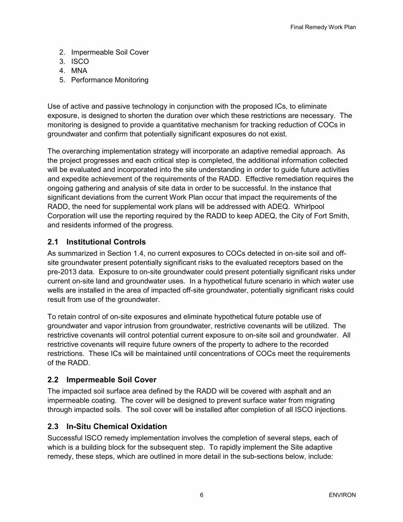
2. Impermeable Soil Cover 3. ISCO 4. MNA 5. Performance Monitoring
Use of active and passive technology in conjunction with the proposed ICs, to eliminate exposure, is designed to shorten the duration over which these restrictions are necessary. The monitoring is designed to provide a quantitative mechanism for tracking reduction of COCs in groundwater and confirm that potentially significant exposures do not exist.
The overarching implementation strategy will incorporate an adaptive remedial approach. As the project progresses and each critical step is completed, the additional information collected will be evaluated and incorporated into the site understanding in order to guide future activities and expedite achievement of the requirements of the RADD. Effective remediation requires the ongoing gathering and analysis of site data in order to be successful. In the instance that significant deviations from the current Work Plan occur that impact the requirements of the RADD, the need for supplemental work plans will be addressed with ADEQ. Whirlpool Corporation will use the reporting required by the RADD to keep ADEQ, the City of Fort Smith, and residents informed of the progress.
2.1 Institutional Controls As summarized in Section 1.4, no current exposures to COCs detected in on-site soil and off-site groundwater present potentially significant risks to the evaluated receptors based on the pre-2013 data. Exposure to on-site groundwater could present potentially significant risks under current on-site land and groundwater uses. In a hypothetical future scenario in which water use wells are installed in the area of impacted off-site groundwater, potentially significant risks could result from use of the groundwater.
To retain control of on-site exposures and eliminate hypothetical future potable use of groundwater and vapor intrusion from groundwater, restrictive covenants will be utilized. The restrictive covenants will control potential current exposure to on-site soil and groundwater. All restrictive covenants will require future owners of the property to adhere to the recorded restrictions. These ICs will be maintained until concentrations of COCs meet the requirements of the RADD.
2.2 Impermeable Soil Cover The impacted soil surface area defined by the RADD will be covered with asphalt and an impermeable coating. The cover will be designed to prevent surface water from migrating through impacted soils. The soil cover will be installed after completion of all ISCO injections.
2.3 In-Situ Chemical Oxidation Successful ISCO remedy implementation involves the completion of several steps, each of which is a building block for the subsequent step. To rapidly implement the Site adaptive remedy, these steps, which are outlined in more detail in the sub-sections below, include:

Final Remedy Work Plan
7 ENVIRON
1. Pre-Design 2. Bench Scale Testing 3. Adaptive Remedy Implementation
This remedial process incorporates a phased approach including a pre-design phase (for which the field work has been completed) followed by an adaptive remedy implementation that will include multiple phases that could include multiple rounds of chemical oxidant injections. The purpose of the pre-design phase was to gather additional information to ensure that the proper oxidant is being used and it is delivered in the correct quantity, as well as to further refine COC characterization. The adaptive remedy implementation involves multiple phases of work. Each phase will include rapid data collection and evaluation following the chemical oxidation injections. This data will then be used to guide subsequent phases of injections. While three areas have been predefined for treatment (Figure 3), these areas may be modified if future data or results indicate that treatment in other or additional areas would be more beneficial.
2.3.1 Pre-Design The first component of a successful ISCO treatment plan for the site is the completion of pre-design activities, which were initiated prior to the completion of the Final RADD with the approval of ADEQ. The field work element of this pre-design work has been completed. Building on current site data, the pre-design activities were conducted in order to fully develop COC characterization necessary for the final remedy design within the three proposed injection locations.
The effectiveness of previous ISCO applications was reduced due to back diffusion and a site characterization that was not thoroughly developed. Therefore, it is critically important to further understand the formation and location of the transmissive zones, the characterization of the COC mass, the hydraulic conductivity of all of the layers (or lenses) within the transmissive zone, the availability of an oxidant to oxidize COCs within site-specific soils, and amount of oxidant required to effectively oxidize COCs to below target levels.
Results from pre-design activities will also assist in determining correct oxidant delivery methods. If the zone of contamination is thicker (in depth) than previously identified, and if radius of influence tests produce smaller effective areas than the 10-foot radius of influence identified in previous pilot studies, then other oxidant delivery methods such as the Lang Tool in-situ mixing method may be evaluated in lieu of injection wells. The results of the pre-design work are currently under review and evaluation and will be incorporated during the adaptive remedy phase as necessary.
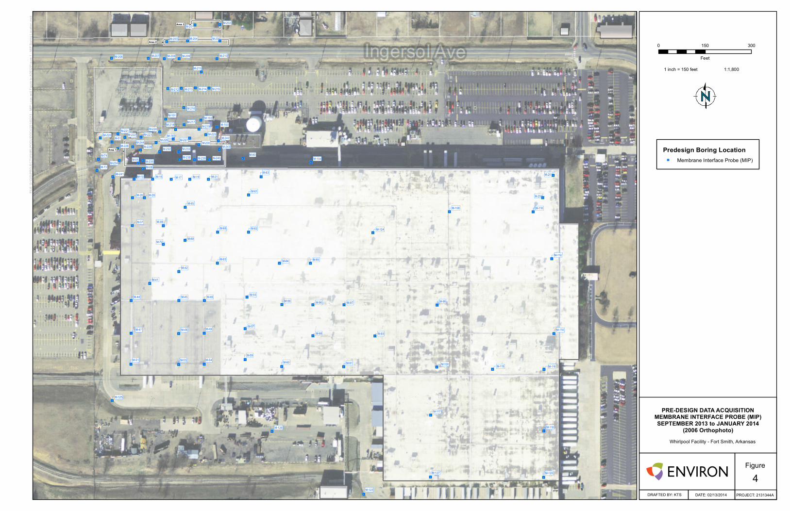
Areas 1, 2, and 3 are defined on Figures 4, 5, and 6. Field work associated with pre-design efforts was completed in September and December 2013 and January 2014. Completed field work includes:
x Geoprobe soil borings with continuous Membrane Interface Probe (MIP) profiling to generate screening data to refine and focus further Geoprobe efforts;
x Geoprobe soil borings and groundwater sampling to refine the extent of COCs;

Final Remedy Work Plan
8 ENVIRON
x Geoprobe soil borings to collect groundwater and saturated soil samples for bench testing for oxidant selection and oxidant demand;
x Geoprobe borings for continuous Hydraulic Profiling Tool (HPT) and Electrical Conductivity (EC) profiling to determine slug test intervals; and
x Geoprobe borings to complete discrete interval slug testing.
MIP logs were included in the 4th Quarter 2013 Progress Report submitted to ADEQ on February 14th, 2014, and an evaluation of the remaining predesign data will be included in the 1st Quarter 2014 Progress Report.
2.3.2 Bench Scale Testing The second step in the successful implementation of the ISCO treatment is the completion of bench scale testing. Bench scale testing is required in order to identify the appropriate oxidant to use in the implementation of the remedy. Bench scale testing began on January 9, 2014.
In order to complete the bench scale testing on impacted soils and groundwater from the site, samples were collected from Areas 1 through 3 as shown on Figures 5 and 6 (noted as SLUG-01, 02, and 06). These samples were submitted to a lab for bench scale testing and screening. During this bench scale testing, base activated sodium persulfate, modified Fenton’s reagent, and modified Fenton’s reagent activated sodium persulfate were reviewed for ability to oxidize COCs at the site. Initial results were received on February 18, 2014 and final results are expected in March 2014.
2.3.3 Adaptive Remedy Implementation The final step in the ISCO treatment is implementation of a chemical oxidant injection. In order to expedite the remediation schedule, while still ensuring that we follow the science based, step-by-step process required for successful ISCO treatment, we will employ an adaptive remedy implementation. This adaptive remedy employs a phased, flexible approach that allows for the fastest time to implementation of the chosen remedial approach. As required by the RADD, the first phase of ISCO treatment will begin on February 24, 2014 with the installation of the injection system components. Quickly thereafter a tracer will be injected followed by injection of an oxidant into select areas. The injected tracer and oxidant will be monitored real time to evaluate their distribution and ability to contact subsurface COCs. Data gathered in this first phase of the adaptive remedy will be used for subsequent phases to further refine the areas selected for injection, amount of oxidant injected (volume and concentration) and the methods used to deliver oxidant to the subsurface.
Permanent wells will be installed during the week of February 24, 2014 for use during the first phase of the adaptive remedy. Temporary points are also planned for use via Geoprobe to allow the greatest flexibility for continued oxidant delivery as required in later stages. Assuming injection points will be used as the sole delivery method, these injection points will be screened in the transmissive zone only. Injection points may be added or removed depending upon data gathered during each phase of the remedy.
Final Remedy Work Plan
9 ENVIRON
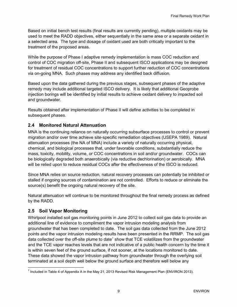
Based on initial bench test results (final results are currently pending), multiple oxidants may be used to meet the RADD objectives, either sequentially in the same area or a separate oxidant in a selected area. The type and dosage of oxidant used are both critically important to the treatment of the proposed areas.
While the purpose of Phase I adaptive remedy implementation is mass COC reduction and control of COC migration off-site, Phase II and subsequent ISCO applications may be designed for treatment of residual COC concentrations to support further reduction of COC concentrations via on-going MNA. Such phases may address any identified back diffusion.
Based upon the data gathered during the previous stages, subsequent phases of the adaptive remedy may include additional targeted ISCO delivery. It is likely that additional Geoprobe injection borings will be identified by initial results to achieve oxidant delivery to impacted soil and groundwater.
Results obtained after implementation of Phase II will define activities to be completed in subsequent phases.
2.4 Monitored Natural Attenuation MNA is the continuing reliance on naturally occurring subsurface processes to control or prevent migration and/or over time achieve site-specific remediation objectives (USEPA 1989). Natural attenuation processes (the NA of MNA) include a variety of naturally occurring physical, chemical, and biological processes that, under favorable conditions, substantially reduce the mass, toxicity, mobility, volume, or COC concentrations in soil and/or groundwater. COCs can be biologically degraded both anaerobically (via reductive dechlorination) or aerobically. MNA will be relied upon to reduce residual COCs after the effectiveness of the ISCO is reduced.
Since MNA relies on source reduction, natural recovery processes can potentially be inhibited or stalled if ongoing sources of contamination are not controlled. Efforts to reduce or eliminate the source(s) benefit the ongoing natural recovery of the site.
Natural attenuation will continue to be monitored throughout the final remedy process as defined by the RADD.
2.5 Soil Vapor Monitoring Whirlpool installed soil gas monitoring points in June 2012 to collect soil gas data to provide an additional line of evidence to compliment the vapor intrusion modeling analysis from groundwater that has been completed to date. The soil gas data collected from the June 2012 points and the vapor intrusion modeling results have been presented in the RRMP. The soil gas data collected over the off-site plume to date1 show that TCE volatilizes from the groundwater and the TCE vapor reaches levels that are not indicative of a public health concern by the time it is within seven feet of the ground surface, if not sooner, at the locations monitored to date. These data showed the vapor intrusion pathway from groundwater through the overlying soil terminated at a soil depth well below the ground surface and therefore well below any 1 Included in Table 4 of Appendix A in the May 21, 2013 Revised Risk Management Plan (ENVIRON 2013).

Final Remedy Work Plan
10 ENVIRON
residential structure. These findings corroborated the groundwater modeling results which indicate vapor intrusion is not occurring at levels that would present a public health concern.
Although the existing soil gas monitoring results provided data that corroborates the conclusion that there is no unacceptable vapor intrusion risk from the Site, Whirlpool concluded that additional soil gas monitoring points should be installed in order to enhance coverage of the off-site plume. As discussed in the RRMP and defined by the RADD, the performance monitoring activities for the site will include a soil gas monitoring plan. The objective of this soil gas monitoring component is to provide additional assurance that the off-site groundwater plume north of the Site does not present a concern for vapor intrusion into the indoor air of buildings overlying the plume. Whirlpool Corporation will evaluate the additional soil gas data following the approach used in the RRMP and as part of the overall evaluation of remedy performance.
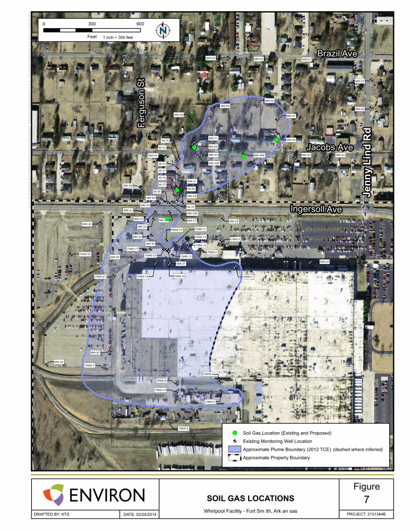
Soil gas monitoring points are being installed consistent with the RADD, where access has been granted. These points are shown on Figure 7. Soil gas samples will be collected using USEPA and industry standard methods and will be analyzed for TCE and breakdown components by an accredited analytical laboratory. Soil cuttings generated during the installation of these monitoring points will be containerized, characterized, and disposed of at a licensed disposal facility.
2.6 Groundwater Monitoring In addition to the enactment of ICs, an impermeable soil cover, ISCO applications, and vapor monitoring, groundwater will also be monitored. Groundwater monitoring will continue to be conducted to confirm that the chosen remedial elements continue to be protective of human health. Groundwater monitoring will be completed in accordance with the RADD.
3 Performance Monitoring As defined by the RADD, Whirlpool Corporation will complete the following performance monitoring and reviews and submit to ADEQ. Whirlpool Corporation will provide copies of all Performance Monitoring documents submitted to ADEQ to the City of Ft. Smith Directors and Administration and access for residents through the Whirlpool Corporation website www.whirlpoolftsmith.com.
3.1.1 Quarterly Performance Monitoring Whirlpool Corporation will prepare quarterly Corrective Action and Operation and Maintenance Status Reports as required in the RADD. The quarterly reports will be due on February 15, May 15, August 15 and November 15 for the previous quarter’s activity. Quarters are based on a calendar year. The quarterly status reports will contain the following:
x Introduction,
x Summaries of Findings in the Reporting Period,
x Review of Activities Completed,
x Data Available,
x Issues Encountered & Resolution, and

Final Remedy Work Plan
11 ENVIRON
x Schedule.
The Quarterly Status Reports will include the following appendix reports as required by the RADD:
x Soil Gas Monitoring Report
x Groundwater Monitoring Report
Included in the 4th Quarter Report, as an addendum, will be an impermeable soil cover assessment report.
3.1.2 Annual Progress Reports Whirlpool will prepare annual progress reports that summarize the results of the remedial activities. The Annual Progress Report will be submitted annually on January 15 to ADEQ, the City of Ft. Smith, and the residents in the two block area defined by Ingersoll, Brazil, Jacobs and Jenny Lind.
3.1.3 Two Year Review As required by the RADD a technical review of the remedial activities and status of the remediation at the site will be prepared and submitted to ADEQ by December 31, 2015. The two year technical review will document the significant reductions in the concentrations of TCE in the treatment area utilizing multiple lines of evidence including validation by comparison to pre-injection analytical and screening data. This technical review will assess the need for necessary further action beyond continued MNA.
3.1.4 Alternative Remedy Plan Based on the results and conclusions of the Two Year Review outlined in 3.1.3, ADEQ may require an alternative remedial plan be prepared by Whirlpool Corporation. The alternative remedial plan must be submitted within thirty (30) days of written notice by ADEQ that ISCO has not been effective in greatly reducing the COCs. The alternative remedy plan will address separate remedial alternatives to address the subsurface soils and on and off-site groundwater.
3.1.5 Five Year Review Consistent with the 2005 Arkansas Groundwater Remediation Level Interim Policy, five years after initiating the Final Remedy, Whirlpool Corporation will submit a comprehensive five-year technical review on December 27, 2018 to detail the status of the Whirlpool site final remedy and assess the need for further actions if necessary.
3.2 Contingency Plan If during the course of the final remedy implementation, progress in meeting remedial action criteria is not satisfactory to both ADEQ and Whirlpool Corporation, additional measures will be undertaken as presented in the RRMP to expedite meeting the remedial action criteria in concurrence with ADEQ participation and approval.

Final Remedy Work Plan
12 ENVIRON
4 Schedule The Work Plan implementation schedule is presented on Figure 9 and represents Whirlpool Corporation’s estimate of the timing for completion of each of the outlined tasks above. The schedule reinforces Whirlpool Corporation’s commitment to an efficient, expeditious implementation program to meet the requirements of the RADD. An overview of the schedule is listed below along with start dates for each task:
x Ongoing Quarterly Groundwater Monitoring, Monitored Natural Attenuation and Soil Vapor Monitoring (next event March 3, 2014)
x ISCO
o Pre-Design
� Field (September and December 2013, January 2014)
� Data Evaluation/Validation (February - March 2014)
o Bench Scale Testing (January - March 2014)
o Adaptive Remedy Implementation
x Phase I (February – April 2014)
x Phase II (May - June 2014)
x Subsequent Phases (Based on results of earlier phases)
x Impermeable Soil Cover (following completion of ISCO)
Various assumptions were made in drafting this schedule, specific assumptions are listed below:
x Vendor and subcontractor schedules/lead times can accommodate the project schedule as submitted.
x Property access issues can be resolved in a timely manner so as not to impact scheduled field work activities.
x Laboratory analytical data will be received within a two week turnaround time.
x Regulatory agencies will review and issue required permits in a timely manner.
The schedule will be reviewed on quarterly basis as part of the performance monitoring. Any schedule revisions will be addressed in the quarterly, two and five year review reports.

Final Remedy Work Plan
ENVIRON
Figures
£¤27 1
Jenn
y Li
nd R
d
Jenn
y Li
nd R
d
Pie
rce
Dr
Ge r e n St
Cy
pre
ss
Av
e
Ho
lly A
ve
Bo
ys C
lub
LnF
erg
uso
n S
t
M a gn o lia D r
Ja co b s Ave
Br az il A ve
In g er s ol Ave Site
Copyright:© 2011 National Geographic Society, i-cubed
0 2,000 4,000
Feet
DRAFTED BY: KTS DATE: 01/17/2014
Figure
PROJECT: 2131344B
FILE
: D:\G
IS\P
RO
JEC
T\W
HIR
LPO
OL\
DO
Cs\
2014
_01_
15_R
AD
D_W
OR
KP
LAN
\Fig
ure
1 - S
ite L
ocat
ion.
mxd
SITE LOCATION
Whirlpool Facility - Fort Smith, Arkansas1
1 inch = 2,000 feet
USGS TopographicQuadrangle Map
Fort Smith
ARKANSASARKANSAS
KANSASKANSASMISSOURIMISSOURI
TEXASTEXAS

£¤271
Jenn
y Li
nd R
d
Jenn
y Li
nd R
d
Pie
rce
Dr
Geren St
Cyp
ress
Ave
Hol
ly A
ve
Boy
s C
lub
Ln
Ferg
uson
St
Magnolia Dr
Jacobs Ave
Brazil Ave
Ingersoll Ave
DRAFTED BY: KTS DATE: 02/24/2014
Figure
PROJECT: 2131344B
FILE
: D:\G
IS\P
RO
JEC
T\W
HIR
LPO
OL\
DO
Cs\
2014
_02_
24_R
evis
ed_R
AD
D_W
OR
KP
LAN
\Fig
ure
2 - S
ite L
ayou
t.mxd
SITE LAYOUT
Whirlpool Facility - Fort Smith, Arkansas2
1 inch = 500 feet
0 500 1,000
FeetApproximate Property Boundary

Jenn
y Li
nd R
d
Jenn
y Li
nd R
d
Ferguson St
Jacobs Ave
Brazil Ave
Ingersol Ave
FILE
: K:\G
IS\PROJE
CT\WHIRLP
OOL\DOCs\20
14 - 20
13 GW Rep
ort\F
igure 2 - 4
th QUARTE
R 2013 TC
E Isoconcentration Map.mxd
DATE: 02/14/2014DRAFTED BY: KTS
Figure
0 200 400
Feet 1 inch = 200 feet
Whirlpool Facility - Fort Smith, Arkansas3
PROJECT: 2131344A
4th QUARTER 2013 TCE ISOCONCENTRATION MAP
TCE Concentration Fall 2013 (mg/L)≤ 0.005
0.005 to 0.10
0.10 to 1.00
1.00 to 10.0
≥ 10.0
TCE Isoconcentration Line (mg/L)0.005 mg/L (inferred)
0.005 mg/L
0.1 mg/L (inferred)
0.1 mg/L
1 mg/L (inferred)
1 mg/L
10 mg/L
Approximate Property Boundary
M-201M-202
M-205M-204
M-209
M-211
M-214M-212
M-216
M-223
M-234
M-243
M-213 M-215
M-206 M-207 M-208
M-203
M-221M-222
M-217
M-240M-239M-238M-235
M-232 M-233
M-230
M-219M-218
M-226
M-229
M-224
M-241
M-228
M-225M-220M-227
M-13 M-15 M-17 M-19 M-21
M-08
M-05
M-01
M-28
M-37
M-29
M-39
M-41
M-44
M-47
M-51
M-45
M-48
M-53
M-42
M-46
M-49
M-54
M-63
M-59
M-57
M-55
M-60
M-56
M-68
M-65
M-69M-72
M-86 M-87
M-91
M-88 M-93
M-125
M-126
M-122
M-81
M-82
M-84 M-85M-83
M-78
M-74
M-73
M-80M-104
M-103
M-102M-101
M-98
M-100
M-117
M-127 M-120
M-118
M-116M-115
M-114
M-112
M-110
M-124
M-108
M-242M-244
M-210
M-250
M-251
" "
""
"
"
""
"
"
"
"
" "
" " "
"
""
"
""""
" "
"
""
"
"
"
"
"
"" "
" " " " "
"
"
"
"
"
"
"
"
"
"
"
"
"
"
"
"
"
"
"
"
"
"
"
"
"
"
""
" "
"
" "
"
"
"
"
"
" ""
"
"
"
""
"
""
"
"
"
" "
"
""
"
"
"
"
"
"
"
"
"
"
6 6
66
6
6
66
6
6
6
6
6 6
6 6 6
6
66
6
6666
6 6
6
66
6
6
6
6
6
66 6
6 6 6 6 6
6
6
6
6
6
6
6
6
6
6
6
6
6
6
6
6
6
6
6
6
6
6
6
6
6
6
66
6 6
6
6 6
6
6
6
6
6
6 66
6
6
6
66
6
66
6
6
6
6 6
6
66
6
6
6
6
6
6
6
6
6
6
Area 1
Area 2
Area 3
FILE
: D:\G
IS\P
RO
JEC
T\W
HIR
LPO
OL\
DO
Cs\
2014
0213
- M
IP L
ogs
and
Figu
re to
AD
EQ
\Fig
ure
1 - M
IP B
orin
g Lo
catio
n.m
xd
Predesign Boring Location"6 Membrane Interface Probe (MIP)
DATE: 02/13/2014DRAFTED BY: KTS
Whirlpool Facility - Fort Smith, Arkansas
4
PRE-DESIGN DATA ACQUISITIONMEMBRANE INTERFACE PROBE (MIP)SEPTEMBER 2013 to JANUARY 2014
(2006 Orthophoto)
PROJECT: 2131344A
Figure
0 150 300
Feet
1 inch = 150 feet 1:1,800

Area 1
BT-03
HPT-07
HPT-06
HPT-05
HPT-08
SLUG-06
SLUG-07
SLUG-08
SLUG-05
M-214M-212
M-216
M-223
M-234
M-243
M-213 M-215
M-221
M-222
M-217
M-240M-239M-238
M-235
M-232 M-233
M-230
M-219M-218
M-226
M-229
M-224
M-241
M-228
M-225M-220
M-227
M-13 M-15 M-17 M-19 M-21
M-08
M-05
M-01
M-28
M-37
M-29
M-39
M-63
M-65
M-81
M-78
M-74
M-73
M-80
M-103
M-102
M-101
M-242
M-244
DP-11DP-09
DP-08
DP-06
DP-05
DP-07
DP-12
""
"
"
"
"
"
" "
"
"
"
""""
" "
"
""
"
"
"
"
"
"
" "
" " " " "
"
"
"
"
"
"
"
"
"
"
"
"
"
"
"
""
"
"
"
"
"
JJ
J
)
J
J
J
J J
J
J
J
JJJJ
J J
J
JJ
J
J
J
J
J
J
J J
J J J J J
J
J
J
J
J
J
J
J
J
J
J
J
J
J
J
JJ
J
J
)
)
)
"
"
"
"
)
)
)
)
C
C
C
C
C
C
C
B
B
B
B
B
B
B
kj
FILE
: D:\G
IS\P
RO
JEC
T\W
HIR
LPO
OL\
DO
Cs\
2014
_02_
24_R
evis
ed_R
AD
D_W
OR
KP
LAN
\Fig
ure
5 - P
re-D
esig
n Te
stin
g Lo
catio
ns -
Are
a 1.
mxd
DATE: 02/24/2014DRAFTED BY: KTS
0 60 120
Feet 1 inch = 60 feet
Whirlpool Facility - Fort Smith, Arkansas PROJECT: 2131344B
Proposed Pre-Design Locations
Boring Type
kj Soil and Groundwater for Bench TestsCB Soil and/or GW Profile/Samples
") Slug Test
") Hydraulic Profiling Tool (HPT)
"J Membrane Interface Probe (MIP)Proposed Treatment AreaApproximate Property Boundary
PRE-DESIGN TESTING LOCATIONS – AREA 1
Figure5

Area 2
Area 3
BT-02
BT-01SLUG-01
SLUG-02
M-201
M-202
M-205M-204
M-209
M-211
M-214M-212 M-213 M-215
M-206 M-207 M-208
M-203
DP-01
DP-02
DP-04DP-03
M-210
" "
""
"
"
"" " "
" "
"
"
J J
JJ
J
J
JJ J J
J J
J
J
"
"
)
)
C C
CC
B B
BB k
k
j
j
FILE
: D:\G
IS\P
RO
JEC
T\W
HIR
LPO
OL\
DO
Cs\
2014
_02_
24_R
evis
ed_R
AD
D_W
OR
KP
LAN
\Fig
ure
6 - P
re-D
esig
n Te
stin
g Lo
catio
ns -
Are
a 2
and
3.m
xd
DATE: 02/24/2014DRAFTED BY: KTS
0 50 100
Feet 1 inch = 50 feet
Whirlpool Facility - Fort Smith, Arkansas PROJECT: 2131344B
Proposed Pre-Design Locations
Boring Type
kj Soil and Groundwater for Bench TestsCB Soil and/or GW Profile/Samples
") Slug Test
"J Membrane Interface Probe (MIP)Proposed Treatment AreaApproximate Property Boundary
PRE-DESIGN TESTING LOCATIONS – AREA 2 AND 3
Figure6
MW-23
ITMW-4
ITMW-6
ITMW-7
ITMW-9
ITMW-10
MW-29
MW-30
ITMW-1
ITMW-3
ITMW-17
ITMW-20
MW-22
MW-24
MW-26MW-27 MW-28
MW-31
MW-33
MW-36
MW-40
MW-39
MW-41
MW-46RMW-43
MW-42B
ITMW-2
ITMW-13
ITMW-14
ITMW-16
ITMW-19
MW-25
ITMW-18ITMW-21
MW-50
MW-37
MW-55
MW-56
MW-57
MW-58
MW-60 MW-61
MW-62 MW-63
MW-38
MW-66
MW-67
MW-68
IW-72
IW-73
IW-77
IW-78
IW-75
ITMW-5
MW-34
MW-35R
ITMW-11
ITMW-12ITMW-15
MW-32
MW-65
MW-71
RW-69
IW-74
IW-76
IW-80
IW-79
@A
@A@A
@A
@A
@A@A
@A
@A
@A
@A
@A@A
@A
@A@A @A
@A @A
@A @A@A
@A
@A
@A
@A
@A@A@A
@A @A@A
@A
@A@A
@A
@A
@A
@A
@A
@A
@A
@A
@A @A
@A @A
@A
@A
@A
@A
@A
@A@A
@A
@A
@A
@A
@A@A@A@A
@A
@A
@A
@A@A
@A
!(
!(
!(
!(
!( Jenn
y Li
nd R
d
Jenn
y Li
nd R
d
Ferg
uson
St
Brazil Ave
Jacobs Ave
Ingersoll Ave
DRAFTED BY: KTS DATE: 02/24/2014
Figure
PROJECT: 2131344B
FILE
: D:\G
IS\P
RO
JEC
T\W
HIR
LPO
OL\
DO
Cs\
2013
0707
_Pre
Des
ignW
orkp
lan\
Figu
re 6
- P
ropo
sed
Add
ition
al S
oil G
as L
ocat
ions
.mxd
SOIL GAS LOCATIONSWhirlpool Facility - Fort Sm ith, Ark an sas
7
0 300 600
Feet 1 inch = 300 feet
!( Soil Gas Location (Existing and Proposed)
@A Existing Monitoring Well Location
Approximate Plume Boundary (2012 TCE) (dashed where inferred)
Approximate Property Boundary

PROTECTIVE COVER
1/4-INCH TEFLON ORNYLON TUBING
6-INCH STAINLESS STEEL SCREEN
1/4-INCH TEFLON ORNYLON TUBING
SAND PACK(TYPICALLY #5 QUARTZ SAND)
HYDRATEDBENTONITE
SAND PACK(TYPICALLY #5 QUARTZ SAND)
HYDRATEDBENTONITE
SURFACE
1/4-INCH SWAGELOKTUBING FITTING
AIR-TIGHT BRASS OR PLASTICCOMPRESSION VALVE
6-INCH STAINLESS STEEL SCREEN
DRAFTED BY: DATE:BJK\TSP 07/08/2013
TYPICAL NESTED SOIL GASMONITORING POINT CONSTRUCTION DETAILS
WHIRLPOOL CORPORATION6400 JENNY LIND ROAD
FORT SMITH, ARKANSAS
FIGURE
82131344B

ID Task�Name Duration Start Finish
1 ADEQ�Issues�Final�RADD 0�days Fri�12/27/13 Fri�12/27/13
2 Annual�Progress�Report 14�days Wed�1/8/14 Fri�1/24/14
3 OnͲSite�Institutional�Controls�Recorded�
40�days Wed�1/1/14 Mon�2/24/14
4 Final�Remedy�Work�Plan 42�days Mon�12/30/13Mon�2/24/14
5 Work�Plan 20�days Mon�12/30/13 Fri�1/24/14
6 Revised�Work�Plan 5�days Tue�2/18/14 Mon�2/24/14
7 Soil�Vapor�Sample�Points 82�days Mon�11/4/13 Mon�2/24/14
11 ISCO:�PreͲDesign 121�days Mon�11/4/13 Fri�4/18/14
16 Adaptive�Remedy�Full�Scale�Treatment�Program
395�days Mon�2/24/14 Fri�8/28/15
28 Two�Year�Technical�Review�Report 84�days Mon�9/7/15 Thu�12/31/15
30 Quarterly�Groundwater�&�Vapor�Sampling
1417�days Sun�3/2/14 Mon�8/5/19
53 1st�Quartely�Progress�Report 1305�days Sat�2/15/14 Fri�2/15/19
60 2nd�Quartely�Progress�Report 1305�days Thu�5/15/14 Wed�5/15/19
67 3rd�Quartely�Progress�Report 1305�days Fri�8/15/14 Thu�8/15/19
74 4th�Quartely�Progress�Report 1305�days Sat�11/15/14 Fri�11/15/19
81 Annual�Progress�Report 1566�days Wed�1/15/14 Wed�1/15/20
12/27
2/24
2/24
1/24
12/31
Qtr�3 Qtr�4 Qtr�1 Qtr�2 Qtr�3 Qtr�4 Qtr�1 Qtr�2 Qtr�3 Qtr�4 Qtr�1 Qtr�2 Qtr�3 Qtr�4 Qtr�12014 2015 2016 2017
Task
Split
Milestone
Summary
Project�Summary
External�Tasks
External�Milestone
Inactive�Task
Inactive�Milestone
Inactive�Summary
Manual�Task
DurationͲonly
Manual�Summary�Rollup
Manual�Summary
StartͲonly
FinishͲonly
Deadline
Progress
Whirlpool�Ft.�Smith�Ͳ�Final�Remedy�Work�Plan�Schedule
Page�1
Figure�9Date:�Mon�2/24/14