FINAL Purslow Weld Repair Mn Frogs for Enhanced … · Weld Repair of Manganese Frogs for Enhanced...
20
Weld Repair of Manganese Frogs for Enhanced Safety in Shared Service Marc A. Purslow, EWI, 1250 Arthur E. Adams Drive, Columbus, OH 43221 614 . 688 . 5150; [email protected] Cameron D. Stuart, Federal Railroad Administration, 1200 New Jersey Avenue S.E., Washington, D.C. 20590 202 . 493 . 6384; [email protected] Yim Har Tang, Volpe National Transportation Systems Center, Kendall Square, Cambridge, MA 02142-1092 617 . 494 . 2717; [email protected] Number of Words: 5,239; 11 figures and tables. ABSTRACT Current methods of repairing worn or damaged manganese steel turnout frogs typically cannot achieve original durability. Welding of austenitic manganese steels requires rapid cooling rates, low heat inputs, and minimal heating of the base material to produce desirable properties. The currently used processes are shielded metal arc welding (SMAW) and self-shielded flux cored arc welding (FCAW), with techniques designed to limit heat build- up. These practices effectively limit the interpass temperature of the base material; however, productivity may be significantly decreased. When track time is limited, repairs cannot be properly completed within the time allotted. In these cases, only a portion of the frog can be repaired and the height mismatch results in additional damage to the frog before the repair can be completed. EWI partnered with the Federal Railroad Administration (FRA) and Transportation Technology Center, Inc. (TTCI) to investigate methods of improving weld quality, increasing durability and productivity with automation and advanced arc welding processes. CSX Corporation provided additional industry input. Automated welding trials were conducted in standard CV (constant voltage) mode, with a specialized system capable of welding in short- circuit mode with reciprocating wire feed (RWF). Automation reduced the calculated heat input by as much as 65 percent compared to baseline manual SMAW and FCAW techniques, while increasing the overall deposition rate. Heat input was further reduced with RWF FCAW. Background Cast Austenitic Manganese Steels (AMS) frogs and crossing diamonds are among the shortest-lived track segments. A study conducted in 1997 reported that approximately 6,800 frogs were replaced each year at a cost of approximately $120 million USD. The same study reports that another $120 million USD was spent on frog maintenance each year.(1) The average life of these cast manganese components drops sharply after the first repair, with repaired frogs lasting approximately half as long as new frogs under similar service conditions. Studies show that the majority of repairs are of “breakouts” or cracks. Breakouts occur when the frog casting has not been sufficiently work-hardened and plastically deforms. This damaged material often acts as the initiation point for cracks and can lead to large pieces of rail breaking off when coming into contact with railroad wheels. A survey of railroad maintenance policies determined the ideal maintenance grinding interval for repaired frogs. Generally, frogs should be inspected and ground after one day, one week, one month, and then every 20 million gross tons (MGT). The report from which these data were taken indicates that welders are often too busy making welding repairs to keep up with these recommendations.(1) This statement was verified by a CSX Corporation welding supervisor. AMS has a high work-hardening capacity and high resistance to wear, making it an ideal material for frogs. Unlike high-carbon rail steel, the temperature of AMS must be kept as low as possible, and cooled quickly from welding temperatures to allow subsequent transformation of wear surfaces to a hard, tough structure through deformation twinning, particle precipitation and phase change. AWS D15.2 specifies that the temperature measured 1 in. (25 mm) from welding shall not exceed 500°F (260°C).(2) Exceeding this temperature will result in a degradation of material properties, particularly the toughness and cracking resistance of hardened layers. The currently used processes in repairing railroad manganese frogs are shielded metal arc welding (SMAW) and self-shielded flux cored arc welding (FCAW). SMAW uses an electrical arc between a consumable coated electrode © AREMA 2014 1
Transcript of FINAL Purslow Weld Repair Mn Frogs for Enhanced … · Weld Repair of Manganese Frogs for Enhanced...

Weld Repair of Manganese Frogs for Enhanced Safety in Shared Service
Marc A. Purslow, EWI, 1250 Arthur E. Adams Drive, Columbus, OH 43221 614.688.5150; [email protected]
Cameron D. Stuart, Federal Railroad Administration, 1200 New Jersey Avenue S.E., Washington, D.C. 20590
202.493.6384; [email protected]
Yim Har Tang, Volpe National Transportation Systems Center, Kendall Square, Cambridge, MA 02142-1092 617.494.2717; [email protected]
Number of Words: 5,239; 11 figures and tables. ABSTRACT
Current methods of repairing worn or damaged manganese steel turnout frogs typically cannot achieve original durability. Welding of austenitic manganese steels requires rapid cooling rates, low heat inputs, and minimal heating of the base material to produce desirable properties. The currently used processes are shielded metal arc welding (SMAW) and self-shielded flux cored arc welding (FCAW), with techniques designed to limit heat build-up. These practices effectively limit the interpass temperature of the base material; however, productivity may be significantly decreased. When track time is limited, repairs cannot be properly completed within the time allotted. In these cases, only a portion of the frog can be repaired and the height mismatch results in additional damage to the frog before the repair can be completed.
EWI partnered with the Federal Railroad Administration (FRA) and Transportation Technology Center, Inc. (TTCI) to investigate methods of improving weld quality, increasing durability and productivity with automation and advanced arc welding processes. CSX Corporation provided additional industry input. Automated welding trials were conducted in standard CV (constant voltage) mode, with a specialized system capable of welding in short-circuit mode with reciprocating wire feed (RWF). Automation reduced the calculated heat input by as much as 65 percent compared to baseline manual SMAW and FCAW techniques, while increasing the overall deposition rate. Heat input was further reduced with RWF FCAW.
Background Cast Austenitic Manganese Steels (AMS) frogs and crossing diamonds are among the shortest-lived track segments. A study conducted in 1997 reported that approximately 6,800 frogs were replaced each year at a cost of approximately $120 million USD. The same study reports that another $120 million USD was spent on frog maintenance each year.(1) The average life of these cast manganese components drops sharply after the first repair, with repaired frogs lasting approximately half as long as new frogs under similar service conditions. Studies show that the majority of repairs are of “breakouts” or cracks. Breakouts occur when the frog casting has not been sufficiently work-hardened and plastically deforms. This damaged material often acts as the initiation point for cracks and can lead to large pieces of rail breaking off when coming into contact with railroad wheels. A survey of railroad maintenance policies determined the ideal maintenance grinding interval for repaired frogs. Generally, frogs should be inspected and ground after one day, one week, one month, and then every 20 million gross tons (MGT). The report from which these data were taken indicates that welders are often too busy making welding repairs to keep up with these recommendations.(1) This statement was verified by a CSX Corporation welding supervisor. AMS has a high work-hardening capacity and high resistance to wear, making it an ideal material for frogs. Unlike high-carbon rail steel, the temperature of AMS must be kept as low as possible, and cooled quickly from welding temperatures to allow subsequent transformation of wear surfaces to a hard, tough structure through deformation twinning, particle precipitation and phase change. AWS D15.2 specifies that the temperature measured 1 in. (25 mm) from welding shall not exceed 500°F (260°C).(2) Exceeding this temperature will result in a degradation of material properties, particularly the toughness and cracking resistance of hardened layers. The currently used processes in repairing railroad manganese frogs are shielded metal arc welding (SMAW) and self-shielded flux cored arc welding (FCAW). SMAW uses an electrical arc between a consumable coated electrode
© AREMA 2014 1
and the base material. The molten pool is shielded by the gasses created when the electrode coating decomposes due to the heat of the arc and the slag covering that forms. Self-shielded FCAW uses an electrical arc between a continuously fed cored consumable electrode and the base material. Decomposition of the electrode core produces gasses and a coating to shield the weld pool. In both processes, the slag covering must be removed via chipping or brushing to avoid slag inclusions which detrimentally affect weld quality. Special welding techniques are used to limit heat build-up. These practices are effective in limiting the interpass temperature of AMS components; however, productivity is also limited. A common approach to increasing productivity and/or reducing heat input is to mechanize or automate the welding process using a solid electrode, which results in a more stable arc. This allows the use of higher currents, deposition rates and travel speeds compared to cored electrodes. Minimal interpass cleaning is required to avoid slag inclusions. Since solid electrodes depend on shielding gas, drafty or windy environments where the gas can be blown away may be problematic. This makes FCAW a common process of choice for outdoor work. Because of this, and since a solid electrode is not commercially available for welding high-AMS components, an FCAW electrode was used in all welding trials. A 75% argon/25% CO2 shielding gas blend was added to improve process stability and reduce welding fume. Welding trials were conducted in CV mode with a conventional power supply and a specialized power supply capable of welding in short circuiting mode with RWF to further reduce heat input, improve process stability, and minimize spatter.
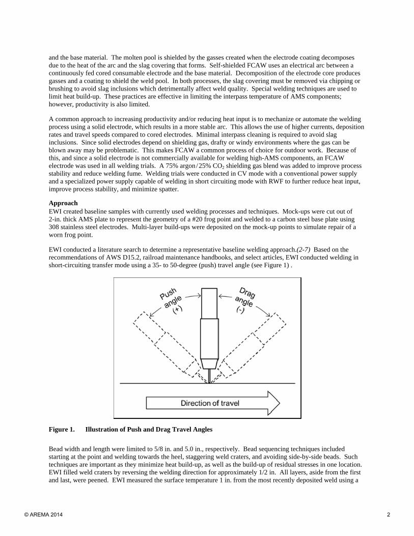
Approach EWI created baseline samples with currently used welding processes and techniques. Mock-ups were cut out of 2-in. thick AMS plate to represent the geometry of a #20 frog point and welded to a carbon steel base plate using 308 stainless steel electrodes. Multi-layer build-ups were deposited on the mock-up points to simulate repair of a worn frog point. EWI conducted a literature search to determine a representative baseline welding approach.(2-7) Based on the recommendations of AWS D15.2, railroad maintenance handbooks, and select articles, EWI conducted welding in short-circuiting transfer mode using a 35- to 50-degree (push) travel angle (see Figure 1) .
Figure 1. Illustration of Push and Drag Travel Angles
Bead width and length were limited to 5/8 in. and 5.0 in., respectively. Bead sequencing techniques included starting at the point and welding towards the heel, staggering weld craters, and avoiding side-by-side beads. Such techniques are important as they minimize heat build-up, as well as the build-up of residual stresses in one location. EWI filled weld craters by reversing the welding direction for approximately 1/2 in. All layers, aside from the first and last, were peened. EWI measured the surface temperature 1 in. from the most recently deposited weld using a
© AREMA 2014 2

contact temperature probe immediately after the termination of the welding arc to determine the maximum temperature. Baseline Welding Baseline welds created with SMAW and self-shielded FCAW were allowed to cool below 250°F between weld beads and 100°F between layers. Baseline SMAW parameters were as follows:
● Electrode diameter: 5/32 in.
● Current: 180 A
● Voltage: 24V
● Travel speed: 4 to 6 ipm
● Heat input: 45 to 65 kJ / in.
● Deposition rate: 3 lbs /hr.
● Thickness per layer: 0.045 in.
● Time per layer: 20 min. Baseline SMAW parameters were as follows:
● Electrode diameter: 1/16 in.
● Current: 200 A
● Voltage: 27V
● Travel speed: 6 ipm
● Heat input: 60 kJ / in.
● Deposition rate: 7 to 8 lbs /hr.
● Thickness per layer: 0.086 in.
● Time per layer: 6.1 min. Evaluation of Baseline Welds According to AWS D15.2, for the grade of AMS typically used for trackwork, hardness ranges from 185 to 210 Brinell in the as-cast condition, but can increase to a maximum of 550 Brinell after the work-hardening that occurs during normal operation. Baseline SMAW hardness mapping indicated a weld metal hardness range of 230 to 300 Brinell, while hardness mapping of the FCAW cross-section indicated weld metal hardness of 220 to 300 Brinell. Data from both samples indicated that the heat from welding resulted in hardening well below the visible heat affected zone (HAZ). The hardness of the unaffected base material was approximately 220 Brinell, which was slightly above the range of typical hardness provided by AWS D15.2. Radiographic testing (RT) revealed scattered porosity throughout both samples. EWI used all-weld-metal tensile specimens to determine yield strength and ultimate tensile strength. Sub-sized samples were used to ensure that no base material was included in the reduced section of the tensile specimen while limiting the number of passes required. AWS D15.2 lists a tensile strength range of 100 to 145 ksi and a yield strength range of 50 to 57 ksi for as-cast AMS components. The measured average ultimate tensile strength (UTS) was 116.57 ksi, and the average yield strength (YS) was 83.33 ksi for the SMAW mock build-up. While the UTS is within the range for the grade of AMS typically used for special track work according to AWS D15.2, the YS was significantly higher. The average UTS of the FCAW mock build-up is 95.97 ksi, which is below the range for the grade of AMS typically used for track work. The average YS was 73.87 ksi, which is above the range of typical values. Automated FCAW Trials EWI developed automated parameters on a 6-axis welding robot using a 0.045-in. self-shielded FCAW electrode. A shielding gas mix of 75% argon and 25% CO2 was used to improve arc stability, decrease fume generation, and improve visibility. In all weld trials to this point, EWI used a 15-degree push travel angle based on the recommendations of the literature search. While these recommendations called for a push angle of 35 to 50 degrees, large angles are not typically used in automated arc welding. EWI conducted automated weld trials with a 15-degree drag angle to evaluate whether slag inclusions could be further reduced or eliminated by directing the arc
© AREMA 2014 3

force and molten slag backwards. This technique avoids running over slag and trapping it at the bottom of the weld bead. EWI developed two sets of welding parameters. The lower heat-input parameter used a travel speed of 15 inches per minute, 140 amps and 21 volts, resulting in a heat input of 12 kJ/in. The goal of this parameter set was to allow weld beads to be deposited on a corner without drooping or rolling off and without the use of a carbon block. The higher heat-input parameter used the same travel speed of 15 inches per minute, 200 amps and 28 volts, resulting in an increased heat input of 23.5 kJ/in. The goals of this parameter set were to create a flat weld bead to allow for adequate tie-in when welding in the middle of the mock-up, and to provide adequate heat to reduce slag inclusions. The deposition rates of the low and high heat input parameters were 6 and 10 lbs /hour, respectively.
EWI created a build-up using the parameters described above and evaluated it using RT. Fewer slag inclusions were found than in previous automated FCAW build-ups and no porosity was observed. The hardness of the weld metal ranged from 250 to 320 Brinell, with hardening well below the visible HAZ. An area of higher hardness in the center may be an indication that the higher heat-input parameters used for center beads resulted in more heat build-up than the previously used FCAW parameters. The average UTS of 125 ksi is within the AWS-supplied range for as-cast AMS components, and were similar to the baseline SMAW data. The higher average YS of 83 ksi may reduce plastic “flow”, and has the potential to positively impact overall durability while reducing required grinding.
Reciprocating Wire Feed (RWF) FCAW Trials
RWF GMAW is a variation of the GMAW process in which the wire motion is synchronized with a current waveform. When the electrode is being fed towards the weld pool, the current is at its peak and a ball is formed at its end. When the electrode contacts the weld pool, the current is decreased, and the ball detaches due to the combination of surface tension forces and retraction of the wire. Since no electrical shorting occurs, minimal spatter is produced. Another advantage of RWF GMAW is that it can be operated at low voltages, resulting in low heat input levels. While RWF is traditionally used with solid electrodes, EWI has successfully used RWF with cored wires. EWI combined RWF with an FCAW consumable to evaluate it as a method of decreasing heat input, improving process consistency and productivity through automation.
EWI conducted parameter development trials using a 0.045-in. diameter electrode and 75% argon/25% CO2 shielding gas. A 15-degree drag angle was used to improve arc stability and decrease the risk of slag entrapment in the weld. As in FCAW development trials, EWI developed two welding parameter sets. The lower heat input parameter used a travel speed of 24 inches per minute, 150 amps and 17.5 volts, resulting in a heat input of 7 kJ/in. The goal of this parameter set was to allow weld beads to be deposited on a corner without drooping or rolling off and without the use of a carbon block. The higher heat input parameter used a travel speed of 13 inches per minute, 195 amps and 18.5 volts, resulting in heat input of 15.7 kJ/in. A weave was added to the higher-heat input parameters to promote improved wetting and tie-in. The goals of this parameter set were to create a flat weld bead to allow for adequate tie-in when welding in the middle of the mock-up and to reduce slag inclusions.
EWI created a build-up and evaluated it using RT. As in the automated FCAW build-up, EWI used the lower-heat input parameters on the corners and the higher-heat input parameters in the center. No porosity was found. However, more slag inclusions were found in the RWF FCAW build-up than in the automated FCAW build-up. Weld metal hardness ranged from 250 to 320 Brinell. Areas of peak hardness were spread throughout the cross section. The average UTS of 121 ksi was within the AWS-supplied range for as-cast AMS components and was similar to the baseline SMAW data. The higher average YS of 86 ksi may reduce plastic “flow”, and has the potential to positively impact overall durability while reducing required grinding. Table 1 provides an overview of tensile testing results for all build-ups from Task 1 and Task 2.
© AREMA 2014 4
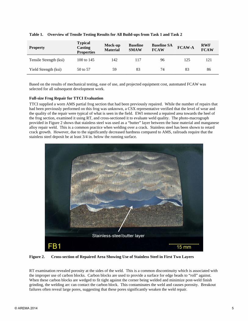
Table 1. Overview of Tensile Testing Results for All Build-ups from Task 1 and Task 2
Property Typical Casting Properties
Mock-up Material
Baseline SMAW
Baseline SA FCAW
FCAW-A RWF FCAW
Tensile Strength (ksi) 100 to 145 142 117 96 125 121
Yield Strength (ksi) 50 to 57 59 83 74 83 86
Based on the results of mechanical testing, ease of use, and projected equipment cost, automated FCAW was selected for all subsequent development work. Full-size Frog Repair for TTCI Evaluation
TTCI supplied a worn AMS partial frog section that had been previously repaired. While the number of repairs that had been previously performed on this frog was unknown, a CSX representative verified that the level of wear and the quality of the repair were typical of what is seen in the field. EWI removed a repaired area towards the heel of the frog section, examined it using RT, and cross-sectioned it to evaluate weld quality. The photo-macrograph provided in Figure 2 shows that stainless steel was used as a “butter” layer between the base material and manganese alloy repair weld. This is a common practice when welding over a crack. Stainless steel has been shown to retard crack growth. However, due to the significantly decreased hardness compared to AMS, railroads require that the stainless steel deposit be at least 3/4 in. below the running surface.
Figure 2. Cross-section of Repaired Area Showing Use of Stainless Steel in First Two Layers RT examination revealed porosity at the sides of the weld. This is a common discontinuity which is associated with the improper use of carbon blocks. Carbon blocks are used to provide a surface for edge beads to “roll” against. When these carbon blocks are wedged to fit tight against the corner being welded and minimize post-weld finish grinding, the welding arc can contact the carbon block. This contaminates the weld and causes porosity. Breakout failures often reveal large pores, suggesting that these pores significantly weaken the weld repair.
© AREMA 2014 5
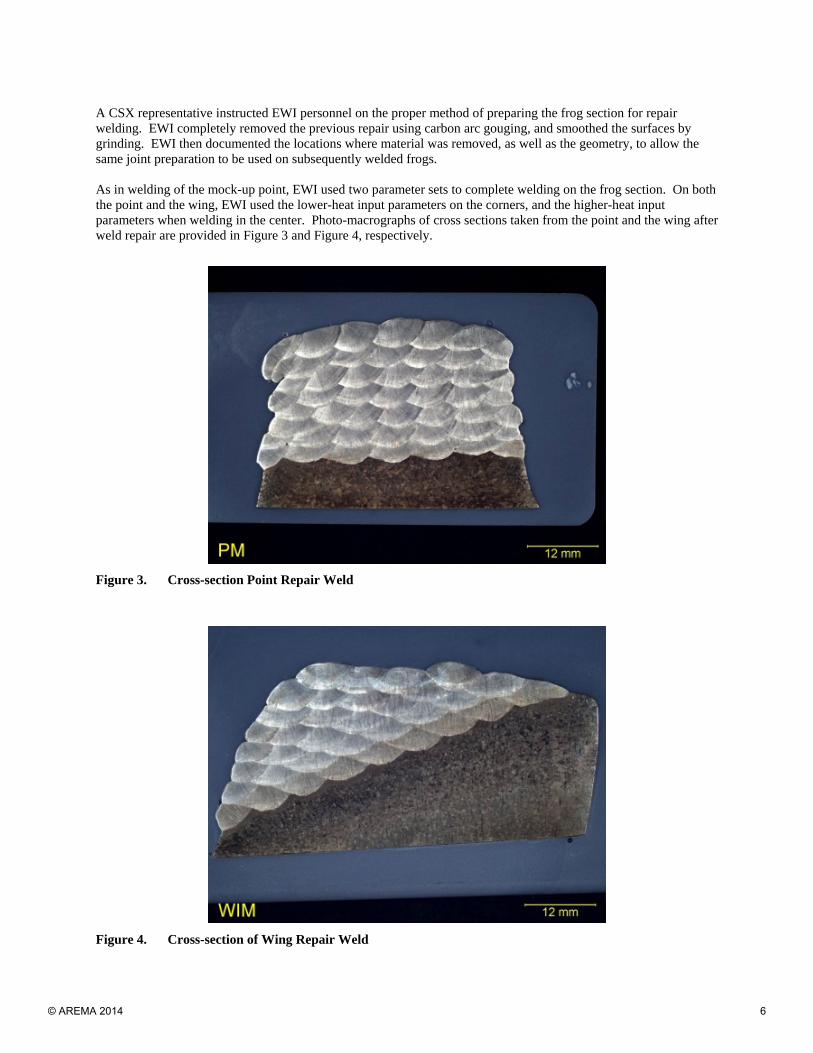
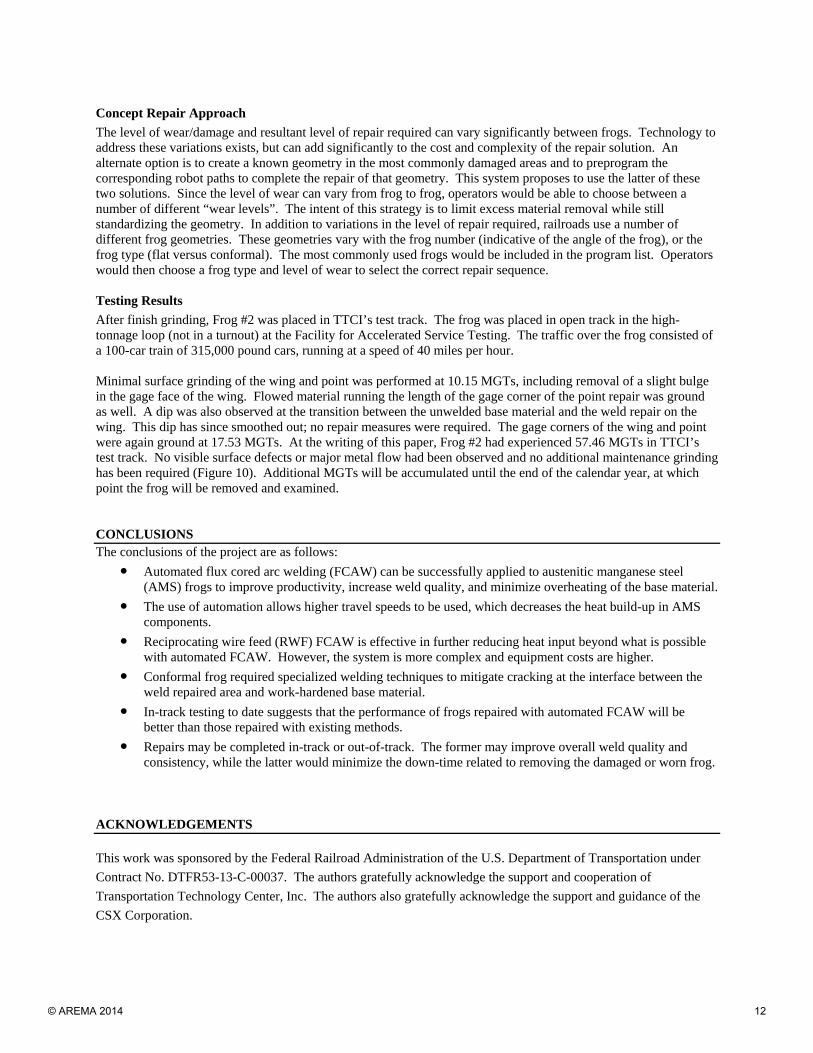
A CSX representative instructed EWI personnel on the proper method of preparing the frog section for repair welding. EWI completely removed the previous repair using carbon arc gouging, and smoothed the surfaces by grinding. EWI then documented the locations where material was removed, as well as the geometry, to allow the same joint preparation to be used on subsequently welded frogs. As in welding of the mock-up point, EWI used two parameter sets to complete welding on the frog section. On both the point and the wing, EWI used the lower-heat input parameters on the corners, and the higher-heat input parameters when welding in the center. Photo-macrographs of cross sections taken from the point and the wing after weld repair are provided in Figure 3 and Figure 4, respectively.
Figure 3. Cross-section Point Repair Weld
Figure 4. Cross-section of Wing Repair Weld
© AREMA 2014 6

TTCI also supplied EWI with two full-length frogs, herein referred to as “Frog #1” and “Frog #2”, for repair and subsequent placement in their test track for evaluation. Frog #1 was a conformal frog, and had more wear, namely “breakouts” on both wings. The cross-section profile of a conformal frog more closely matches the profile of the wheel to reduce material flow and wear rates. Frog #2 was a flat frog, and had minimal wear from 6.8 MGTs of traffic. EWI repaired the point, and the “point facing left” wing, of each frog. The “point facing right” wings were not repaired since TTCI’s plan was to test only one wing in-track. EWI removed sufficient material to mimic a field repair, based on the amount of material removed from the partial frog. The repaired point sections of both frogs were extended towards the heel to simulate repair of the area that was cut out for RT cross-sectioning as illustrated in Figure 5.
Figure 5. Material Removal Illustration
As with the partial frog, EWI used carbon arc gouging to complete the bulk of the required material removal. EWI then ground both frogs smooth to prepare for weld repair. The weld approach was based on welding of the partial frog. EWI used the lower-heat input parameters on the corners and the higher-heat input parameters in the center. Six layers were required to build-up the wing of Frog #1. The number of beads per layer decreased with successive weld layers. Throughout welding of the wing, the maximum interpass temperature reached 219°F when measurements were taken 1 in. from the weld.
Frog #1
The maximum interpass temperature reached 228°F during welding of the point when measurements were taken 1 in. from the weld. Seven layers were required to build the point up to the required height. Upon the recommendation of CSX welding supervisors, EWI deposited additional material at the heel of the frog to ensure a smooth transition between the weld repaired area and the unwelded area. Prior to depositing this material, EWI removed 0.125 in. of adjacent material to ensure that welds were not deposited on work-hardened material which would be more prone to cracking. Four layers of weld were required to build up this area to allow for a smooth transition. The maximum interpass temperature reached during the deposition of these layers was 235°F. EWI observed cracks oriented transverse to the welding direction in the base material during welding of the transition area as shown in Figure 6. EWI ground these cracks out and removed 0.125 in. of material from the adjacent area. EWI extended the grinding into the previously welded area to determine if cracks extended into the weld. However, none was found using dye penetrant testing. Since the cracks extended 0.25-in. deep, EWI filled these areas and ground the surface smooth before depositing subsequent layers. EWI reversed the welding direction of the first two layers, progressing from the heel towards the point. This technique was used because the end of an arc weld (referred to as the “crater”) is typically hotter than the start of the weld. This can result in higher residual stresses at the crater than at the weld
© AREMA 2014 7

start. Since cracking is often related to the build-up of residual stresses, EWI concluded that the likely cause of cracking was the combination of work-hardened base material and high residual stresses at the location of multiple adjacent weld craters. Since the start of the weld was “colder”, EWI reversed the welding direction of the first two layers to minimize heat and residual stresses at the transition from ground material to unground, work-hardened base material. EWI deposited the third layer in the original welding direction to even out the build-up and ensure the proper height.
Figure 6. Base Material Cracking in Frog #1
The repair sequence used on the point of Frog #1 is summarized below and illustrated in Figure 7.
(1) The original point geometry was documented.
(2) EWI removed material to simulate a worst-case-scenario field repair using carbon arc gouging and grinding.
(3) EWI deposited 7 layers to build-up the removed material. Layers were 9 to 10 beads wide.
(4) EWI removed additional material towards the heel of the point to create a smooth transition according to the recommendation of CSX personnel.
(5) EWI deposited four layers to build up the removed material in the transition area. Two cracks were found in the base material adjacent to the weld craters during dye penetrant testing.
(6) EWI removed the cracks by grinding, and removed 0.125 in. of material from the adjacent surface area.
(7) After filling the deep area where the cracks were removed and grinding the area flush, EWI deposited two layers in the opposite direction of all other welding passes to minimize heating the unground, work-hardened base material. An additional layer was deposited in the original direction to even out the height of the build-up.
© AREMA 2014 8

(8) TTCI ground the frog to final shape.
Figure 7. Illustration of Frog #1 Point Repair Sequence After grinding the frog to shape to prepare for in-track testing, TTCI found a crack in the point of Frog #1. As in the crack found in the heel of Frog #1, the crack was located in the base material adjacent to the weld-repaired area. Due to this defect, Frog #1 was not placed into TTCI’s test track for evaluation. At the time this paper was written, EWI was determining a path forward on the repair and subsequent testing of this frog. Frog #2
EWI applied the same approach used on Frog #1 to weld Frog #2. Throughout welding of the wing, the maximum interpass temperature reached 219F when measurements were taken 1 in. from the weld. Six layers were required to build up the wing to the required height. EWI deposited eight layers on the point to build up the removed material. The maximum interpass temperature measured 1 in. from the weld was 242°F. Upon the recommendation of CSX welding supervisors, EWI deposited additional material at the heel of the frog to ensure a smooth transition between the weld repaired area and the unwelded area. EWI ground the surface to a depth of 0.125 in. to ensure that welds were not deposited on work-hardened material which would be more prone to cracking. Two layers were required to build up this area to match the height of the previously welded section. The maximum interpass temperature of 220°F was reached during the deposition of these layers. Three additional layers spanning the full length of the original repair section, and the additional “transition” repair, were deposited to ensure there was sufficient material for grinding. The maximum interpass temperature reached during the deposition of these three layers was 239°F. The repair sequence used on the point of Frog #2 is summarized below and illustrated in Figure 8.
© AREMA 2014 9

Figure 8. Frog #2 Repair Sequence
(1) The original frog geometry was documented.
(2) EWI removed material from the point to simulate a worst-case scenario field repair using carbon arc gouging and grinding.
(3) EWI deposited 8 layers to build up the removed material. Layers were 9 to 10 beads wide.
(4) EWI removed additional material towards the heel of the point according to the recommendation of CSX personnel.
(5) EWI deposited two layers to build up the removed material.
(6) EWI deposited two additional layers that were nearly the full length of the repair to build up the height of the point to match the height of the wings. EWI also deposited one additional, shorter layer to build up a “dip” in the repaired area.
(7) TTCI ground the frog to final shape.
Automated Repair Concepts
The repair approach described above can be applied via two methods. In the first, the frog would be removed from the track and repaired in a facility using equipment similar to that used in EWI’s lab. This method would eliminate issues related to lack of track time to complete the repair. In addition, completing the repair in a more controlled environment by dedicated staff could increase the consistency and quality of repair welds. In-track Automated Repair Concept
EWI created an in-track automation concept, illustrated in Figure 9 and Figure 10. The automation concept includes two 6-axis robots housed in a box truck, along with the required robot power supplies, and a welding power supply. A water tank is mounted on the underside of the truck (not pictured). A supply of abrasive required for water-jet cutting is also stored in the box truck. Linkage allows the robot cart to be lowered onto the track. The robot cart is designed with a cutaway on either side to allow frog repair, regardless of the direction of the truck. A water-jet cutting robot is used to prepare the frog for welding by removing defective material. Welding is then completed by
© AREMA 2014 10

the arc welding robot. It may be possible to complete post-weld preparation using the water-jet cutting robot instead of grinding. If not, post-weld grinding will be completed using existing methods.
Figure 9. Automation Concept Showing Deployed Robot Cart
Figure 10. Frog #2 in TTCI Test Track
© AREMA 2014 11
Concept Repair Approach
The level of wear/damage and resultant level of repair required can vary significantly between frogs. Technology to address these variations exists, but can add significantly to the cost and complexity of the repair solution. An alternate option is to create a known geometry in the most commonly damaged areas and to preprogram the corresponding robot paths to complete the repair of that geometry. This system proposes to use the latter of these two solutions. Since the level of wear can vary from frog to frog, operators would be able to choose between a number of different “wear levels”. The intent of this strategy is to limit excess material removal while still standardizing the geometry. In addition to variations in the level of repair required, railroads use a number of different frog geometries. These geometries vary with the frog number (indicative of the angle of the frog), or the frog type (flat versus conformal). The most commonly used frogs would be included in the program list. Operators would then choose a frog type and level of wear to select the correct repair sequence. Testing Results
After finish grinding, Frog #2 was placed in TTCI’s test track. The frog was placed in open track in the high-tonnage loop (not in a turnout) at the Facility for Accelerated Service Testing. The traffic over the frog consisted of a 100-car train of 315,000 pound cars, running at a speed of 40 miles per hour. Minimal surface grinding of the wing and point was performed at 10.15 MGTs, including removal of a slight bulge in the gage face of the wing. Flowed material running the length of the gage corner of the point repair was ground as well. A dip was also observed at the transition between the unwelded base material and the weld repair on the wing. This dip has since smoothed out; no repair measures were required. The gage corners of the wing and point were again ground at 17.53 MGTs. At the writing of this paper, Frog #2 had experienced 57.46 MGTs in TTCI’s test track. No visible surface defects or major metal flow had been observed and no additional maintenance grinding has been required (Figure 10). Additional MGTs will be accumulated until the end of the calendar year, at which point the frog will be removed and examined. CONCLUSIONS The conclusions of the project are as follows:
● Automated flux cored arc welding (FCAW) can be successfully applied to austenitic manganese steel (AMS) frogs to improve productivity, increase weld quality, and minimize overheating of the base material.
● The use of automation allows higher travel speeds to be used, which decreases the heat build-up in AMS components.
● Reciprocating wire feed (RWF) FCAW is effective in further reducing heat input beyond what is possible with automated FCAW. However, the system is more complex and equipment costs are higher.
● Conformal frog required specialized welding techniques to mitigate cracking at the interface between the weld repaired area and work-hardened base material.
● In-track testing to date suggests that the performance of frogs repaired with automated FCAW will be better than those repaired with existing methods.
● Repairs may be completed in-track or out-of-track. The former may improve overall weld quality and consistency, while the latter would minimize the down-time related to removing the damaged or worn frog.
ACKNOWLEDGEMENTS
This work was sponsored by the Federal Railroad Administration of the U.S. Department of Transportation under
Contract No. DTFR53-13-C-00037. The authors gratefully acknowledge the support and cooperation of
Transportation Technology Center, Inc. The authors also gratefully acknowledge the support and guidance of the
CSX Corporation.
© AREMA 2014 12
REFERENCES
(1) Davis, D., Sun, J., Terrill, V., Hansen, B., “Industry Survey of Frog Weld Repair Best Practices,” Association of American Railroads Research and Test Department Technology Digest, 1997.
(2) Subramanyam, D. K., Swansiger, A. E., Avery, H. S., “Austenitic Manganese Steelss,” ASM Handbook Volume 1, Properties and Selection: Irons, Steels, and High-Performance Alloys, pp. 822-840, 1990.
(3) Handbook for Track Welders: MW&S Standard Procedure for Welding Repairs to Rail and Track Fixtures and Grinding,” Norfolk Southern Corporation, December 1992.
(4) “How to Repair AMS Castings,” Abex Corporation Amsco Division, Bulletin WB-873.
(5) “Instructions Governing the Inspection, Welding, Grinding and Heat Treatment of Track Components,” Union Pacific Railroad Company Engineering Services, November, 1990.
(6) “Recommended Practices for the Welding of Rails and Rail Related Components for Use By Rail Vehicles,” American Welding Society AWS D15.2, pp. 21-23, 2003.
(7) “Welding Alloys for Railroad Track Maintenance,” McKay Technical Report.
LIST OF TABLES AND FIGURES
Table 1. Overview of Tensile Testing Results for All Build-ups from Task 1 and Task 2 ...........................
Figure 1. Illustration of Push and Drag Travel Angles ..................................................................................
Figure 2. Cross-section of Repaired Area Showing Use of Stainless Steel in First Two Layers ...................
Figure 3. Cross-section Point Repair Weld ....................................................................................................
Figure 4. Cross-section of Wing Repair Weld ...............................................................................................
Figure 5. Material Removal Illustration .........................................................................................................
Figure 6. Base Material Cracking in Frog #1 .................................................................................................
Figure 7. Illustration of Frog #1 Point Repair Sequence ................................................................................
Figure 8. Frog #2 Repair Sequence ................................................................................................................
Figure 9. Automation Concept Showing Deployed Robot Cart .....................................................................
Figure 10. Frog #2 in TTCI Test Track ..........................................................................................................
© AREMA 2014 13
Wel
dR
epai
rofM
anga
nese
Wel
d R
epai
r of M
anga
nese
Fr
ogs
for E
nhan
ced
Safe
ty
in S
hare
d Se
rvic
eM
arc
AP
ursl
owM
arc
A. P
ursl
owA
pplic
atio
ns E
ngin
eer
mpu
rslo
w@
ewi.o
rg61
688
10
614.
688.
5150
Slid
e 1
© AREMA 2014 14
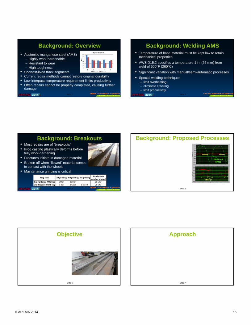
Background: Overview• Austenitic manganese steel (AMS)
– Highly work-hardenable – Resistant to wear– High toughness
Slide 2
High toughness• Shortest-lived track segments• Current repair methods cannot restore original durability • Low interpass temperature requirement limits productivity • Often repairs cannot be properly completed, causing further
damage
Background: Welding AMS• Temperature of base material must be kept low to retain
mechanical properties
• AWS D15.2 specifies a temperature 1 in. (25 mm) from weld of 500F (260C)
Slide 3
( )
• Significant variation with manual/semi-automatic processes
• Special welding techniques– limit overheating – eliminate cracking– limit productivity
Background: Breakouts• Most repairs are of “breakouts”
• Frog casting plastically deforms before fully work-hardening
• Fractures initiate in damaged material
• Broken off when “flowed” material comes
Slide 4
• Broken off when flowed material comes in contact with the wheels
• Maintenance grinding is critical
Frog Type 1st grinding 2nd grinding 3rd grindingSteady‐state
grinding interval
Pre‐hardened AMS frog 5 MGT 20 MGT ‐ 20 MGT
Weld repaired AMS frog 1 day 1 week 1 month 20 MGT
Background: Proposed Processes• Automated FCAW
– Higher travel speeds + wire feed speeds = higher productivity
– More consistent than manual /i t ti ldi
Slide 5
semi-automatic welding
• Reciprocating Wire Feed (RWF) • Wire Motion Synchronized with
Current Waveform– Minimal spatter – Low voltage/heat input RWF current, voltage, and WFS
Objective• Determine whether automating FCAW process
variations can: – Improve weld quality
Slide 6
– Provide quality control – Improve productivity – Increase repair life – Improve ride quality
Approach• Using #20 frog point “mock-ups”
– Evaluate current industry repair techniques
– Evaluate Automated FCAW and RWF FCAW
• Evaluate with mechanical and radiographic testing (RT)
Slide 7
Evaluate with mechanical and radiographic testing (RT)
• Select a single automated process
• Develop welding sequence on AMS frog
• Repair 2 AMS frogs
• Evaluate repaired frogs at TTCI
© AREMA 2014 15

Baseline Welding• Per AWS D15.2, Handbooks• Short-circuiting transfer mode • 35 to 50(push) travel angle• Bead width and length 5/8- and 5-in. • Bead sequencing
Point to heel
Slide 8
– Point to heel– Stagger craters – Avoid side-by-side beads
• Fill craters by reversing direction • Peen all but first and last layers• Maximum temperature of 500 to
600F measured 1 in. from weld
RT/Visual Inspection of Baseline Welds• SMAW
– Heat input: 60 kJ/in.– RT: Scattered porosity throughout– Cross section: 2 vertical cracks
Slide 9
• Semi-automatic FCAW – Heat input: 45 to 65 kJ/in.– RT: Scattered porosity– Improved quality over SMAW
Interpass Temperature Trials• SMAW
• #20 Point mock-ups
• No delay between passes
• Industry recommended vs
Industry Recommended
Slide 10
Industry recommended vs. two EWI sequences
• Staggered long weld beads resulted in lower heat and cycle time
EWI Sequence 1
EWI Sequence 2
Automated FCAW Trials• Solid Electrodes Not Commercially Available
– Self-shielded FCAW Electrode
– 75% Argon/25% CO2 Shielding Gas
• Two Parameter Sets – Corner Parameters
Slide 11
– Corner Parameters• TS: 15 ipm, A: 140, V: 21
• Heat Input: 12 kJ/in. • Corner beads without drooping
– High-deposition Parameters• TS: 15 ipm, A: 200, V: 28
• Heat Input: 23.5 kJ/in.
Reciprocating Wire Feed Trials• Solid Electrodes Not Available
– Self-shielded FCAW Electrode – 75% Argon/25% CO2 Shielding Gas
• Two Parameter Sets Developed– Corner parameters
Slide 12
p• Travel Speed: 24 ipm, A: 150, V: 17.5• Heat Input: 7 kJ/in.• Corner beads without drooping
– High-deposition Parameters• Travel Speed: 13 ipm, A: 195, V: 18.5• Heat Input: 15.7 kJ/in. • Weave added to promote wetting/tie-in
Tensile Testing of Mock-up Welds• All YS higher than D15.2
baseline
• All UTS except SA FCAW
Slide 13
phigher than D15.2 baseline
© AREMA 2014 16
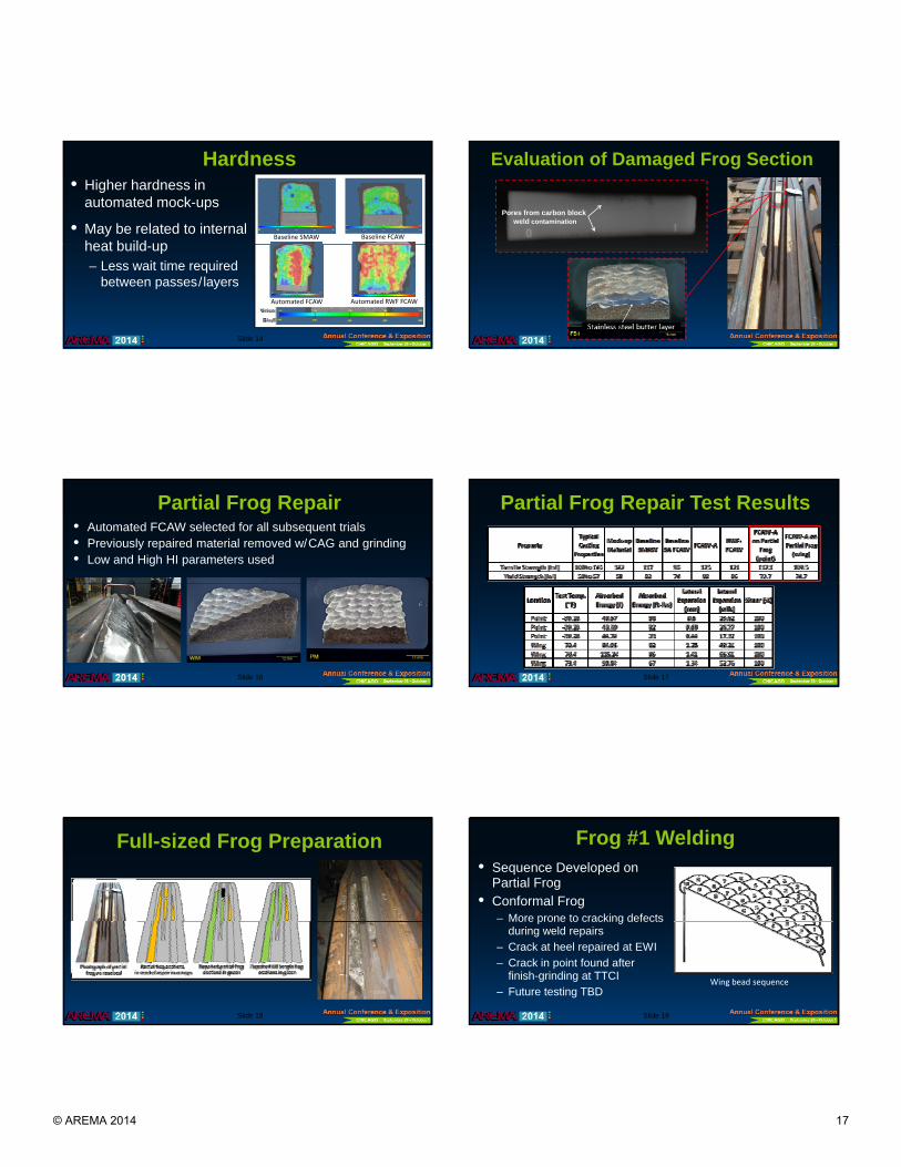
Hardness
Baseline SMAW Baseline FCAW
• Higher hardness in automated mock-ups
• May be related to internal heat build up
Slide 14
Automated FCAW Automated RWF FCAW
heat build-up– Less wait time required
between passes/layers
Evaluation of Damaged Frog Section
Pores from carbon block weld contamination
Slide 15
Partial Frog Repair• Automated FCAW selected for all subsequent trials• Previously repaired material removed w/CAG and grinding• Low and High HI parameters used
Slide 16
Partial Frog Repair Test Results
Slide 17
Full-sized Frog Preparation
Slide 18
Frog #1 Welding• Sequence Developed on
Partial Frog• Conformal Frog
– More prone to cracking defects
Slide 19
More prone to cracking defects during weld repairs
– Crack at heel repaired at EWI
– Crack in point found after finish-grinding at TTCI
– Future testing TBDWing bead sequence
© AREMA 2014 17

Frog #1 Welding
Slide 20
Point Welding Sequence
Heel Crack (EWI)
Point Crack (TTCI)
Frog #1 Heel Crack Repair
Slide 21
Frog #2 Welding• Sequence Developed on Partial Frog
• Flat Frog– Less prone to cracking defects
Slide 22
during weld repairs
– No cracks found during welding or finish grinding
• Currently in TTCI’s Test Track
Frog #2 Welding
Step 4: Grinding preparation for taper-fill layer
Slide 23
Step 5: Welding of taper-fill layer
Automation Concept• Retractable cart
• 6-axis arc welding robot
• 6 i t j t tti b t
Slide 24
• 6-axis water-jet cutting robot
• Need for adaptive fill TBD– Would require vision system
Frog #2 Testing Results• Placed in open track in high-
tonnage loop (HTL) at Facility for Accelerated Service Testing (FAST)
Slide 25
(FAST)– 100-car train
– 315,000 pound cars
– 40 miles per hour
© AREMA 2014 18

Frog #2 Testing Results• 57.46 MGTs to date
• Maintenance grinding at 10.15 MGTs– Bulge in gage face of wing– “Flow” length of point – HAZ dip in wing
Slide 26
HAZ dip in wing
• Maintenance grinding at 17.53 MGTs– Gage corners of wing and point
• No visible surface defects or major metal flow
• No additional maintenance grinding has been required
Frog #2 Testing Results: Hardness Data
Slide 27
Frog #2 Testing Results: Running Surface Wear
0.1
Running Surface WearWing @ 8 in. Past Frog Point
0.1
Running Surface WearFrog Point @ 32 in. Past Frog Point
Slide 28
0
0.02
0.04
0.06
0.08
0.0 10.0 20.0 30.0 40.0 50.0
Area Loss (In
2 )
Tonnage (MGT)
0
0.02
0.04
0.06
0.08
0.0 10.0 20.0 30.0 40.0 50.0
Area Loss (In
2 )
Tonnage (MGT)
Frog #2 Testing Results• Running surface height loss is relatively uniform• Deformation rates have stabilized well before
maintenance limits are reached
R i S f W
Slide 29
0
0.02
0.04
0.06
0.08
0.1
0.0 10.0 20.0 30.0 40.0 50.0
Area Loss (In
2 )
Tonnage (MGT)
Running Surface WearWing @ 8 in. Past Frog Point
Conclusions• Automated FCAW can be successfully applied
to AMS frogs for:– Improved productivity– Increased weld quality
Slide 30
q y– Lower interpass temperatures
• RWF FCAW – Further reduces heat input – Equipment is more complex
Conclusions• Conformal frog required specialized welding
techniques to mitigate cracking at interface between the weld repaired area and work-hardened base material
Slide 31
hardened base material.
• In-track testing to date suggests the performance of frogs repaired with automated FCAW is better than those repaired with existing methods.
© AREMA 2014 19

Acknowledgements • Work was sponsored by the Federal Railroad
Administration of the U.S. Department of Transportation under Contract No. DTFR53-13-C-00037.
• A th t f ll k l d th t d
Slide 32
• Authors gratefully acknowledge the support and cooperation of Transportation Technology Center, Inc.
• Authors also gratefully acknowledge the support and guidance of CSX Corporation.
References1) Davis, D., Sun, J., Terrill, V., Hansen, B., “Industry Survey of Frog Weld
Repair Best Practices,” Association of American Railroads Research and Test Department Technology Digest, 1997.
2) Subramanyam, D. K., Swansiger, A. E., Avery, H. S., “Austenitic AMSs,” ASM Handbook Volume 1, Properties and Selection: Irons, Steels, and
Slide 33
High-Performance Alloys, pp. 822-840, 1990.
3) Handbook for Track Welders: MW&S Standard Procedure for Welding Repairs to Rail and Track Fixtures and Grinding,” Norfolk Southern Corporation, December 1992.
4) “How to Repair AMS Castings,” Abex Corporation Amsco Division, Bulletin WB-873.
References5) Instructions Governing the Inspection, Welding, Grinding and Heat
Treatment of Track Components,” Union Pacific Railroad Company Engineering Services, November, 1990.
6) “Recommended Practices for the Welding of Rails and Rail Related
Slide 34
Components for Use By Rail Vehicles,” American Welding Society AWS D15.2, pp. 21-23, 2003.
7) “Welding Alloys for Railroad Track Maintenance,” McKay Technical Report.
© AREMA 2014 20