Hot water,Direct Fired single and double effect LiBr Absorption Chiller and Heater.pdf

207 TR to 1398 TR (725 kW to 4920 kW)
Hot WaterVapour Absorption Chiller

Vapor Absorption Technology from Thermax is at work for clients in more than 50 industries including Pharmaceuticals, Chemicals, Fertilizers, Steel, Textiles, Petrochemicals, Food & Beverages and Automobile industries as well as in Hotels, Commercial Complexes, Shopping Complexes, Office Buildings, Educational Institutes, Airports, Cinema halls and Medical Centers.
Manufacturing capabilities of Thermax’s Cooling SBU are confirmed by the fact that, over the years, Thermax has installed thousands of machines in more than 70 countries including USA, Brazil, Germany, Spain, UK, Italy, UAE, Saudi Arabia, India, China, Australia, Thailand, Philippines, Malaysia, Russia and Nigeria with the products conforming to the respective country standards like ETL, CE, TUV, DNV, ASME etc. Thermax has its fully owned subsidiaries namely Thermax Inc. in USA, Thermax Europe Limited in UK and Thermax (Zhejiang) Cooling and Heating Engg. Company Limited in China.
Thermax believes in efficient and responsive services to it's clients and exhibits in it's way of business, by giving optimal and quality solutions and achieving customer delight. Thermax has a worldwide sales, service and distribution network to fulfill the needs of it's valuable customers.
The Cooling SBU of THERMAX promotes Vapor Absorption Chillers as a cost effective and environment friendly alternative to electricity driven compression chillers.
It offers expert solutions in Process Chilling & Air Conditioning for industrial as well as commercial applications. Cooling SBU's strength lies in customized solutions as per the requirements of its customers.
Unlike electrical chillers, Absorption Chillers are powered by heat. These machines can run on a variety of heat sources, e.g. steam, hot water, liquid/gaseous fuels, exhaust gases and/or a combination of above.
Cooling & Heating Division - Cooling SBU
To be a globally respected high performance organization offering sustainable solutions in energy and environment.
Vision
From Cooling to Heating, from Power Generation to Air Purification, from Water and Sewage Treatment to Speciality Chemicals, THERMAX Solutions are improving life at work in many ways.
Every year THERMAX helps generate 6,000 MW of Power, produce 100,000 tons of steam, provide 4 billion tons of Cooling and treat 1,000 million litres/day of Water and Waste.
THERMAX today is a major Engineering and Environment company with revenues of USD 800 million and with market capitalization of over USD 1 billion.
THERMAX was one of 20 Indian companies in Forbes list of “Asia’s Best Under a Billion Companies” in 2005 and 2006 and was ranked “No. 1 among the top 21 wealth creators” in India over the last 5 years by a leading investment journal.
THERMAX brings to customers enriched experience of industrial applications, and expertise through technological partnerships and strategic alliances.
Operating from its Headquarters in Pune (Western India), Thermax has built an international sales & service network spread over South East Asia, Middle East, Africa, Russia, UK, US and China. It has full fledged ISO 9001:2000 and ISO 14000 accredited manufacturing setups.
Sustainable Solutions
Corporate office image
Thermax - Conserving Energy,Preserving the Environment
Thermax manufactures environment friendly and energy efficient vapor absorption chillers at its plant in Pune, India and China. Its state-of-the-art manufacturing facility is awarded with ISO 9001 and ISO 14001 certifications. Stringent quality control procedures along with a skilled workforce ensure that a highly reliable product leaves the factory, The equipment and manufacturing processes conform to International standards.
Manufacturing & TestingThermax Pressure part manufacturing has been approved by ASME and bears S, U, H, R stamps. The Vapor absorption chillers are CE certified for European Union and ETL listed for US and Canadian market. They confirm to the Kyoto Protocol & are in absolute tandem with Clean Development Mechanism Code (CDM). Thermax also confirms to Environmental Management System standard 14001 & OHSAS 18001.
CNC twin spindle drilling machine with high speed and direct feed technology ensures fine tube hole finish and accuracy, which is important for leak tight expansion and effective heat transfer.
A Helium leak detection test ensures there is noleak at welding joints.
Welding robot for high precision automatic welding.
CNC gas cutting machine for plate cutting ensures precision cutting of shell plates and profile cut
tube plates.
Press Brake Machine
Press Brake Machine


o39 F.

o39 F.

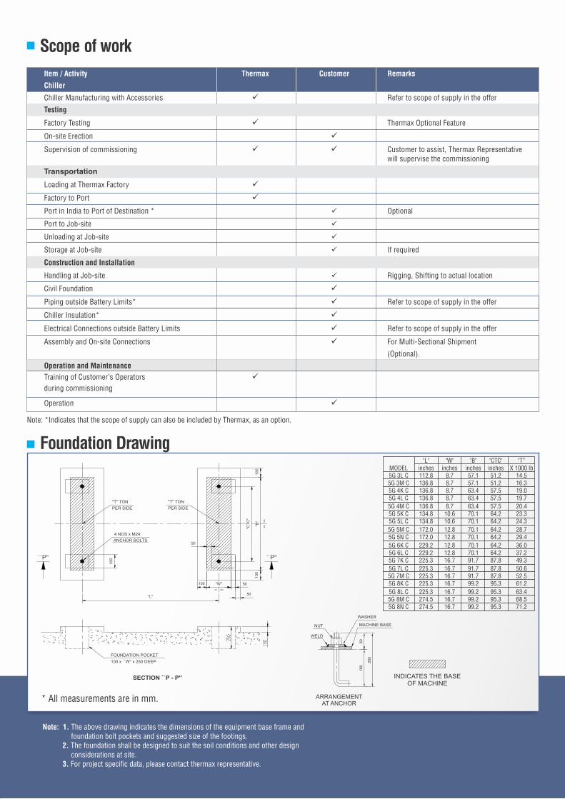
* All measurements are in mm.
"L" "W" "B" "CTC" "T” MODEL inches inches inches inches X 1000 lb 5G 3L C 112.8 8.7 57.1 51.2 14.5 5G 3M C 136.8 8.7 57.1 51.2 16.3 5G 4K C 136.8 8.7 63.4 57.5 19.0 5G 4L C 136.8 8.7 63.4 57.5 19.7
5G 4M C 136.8 8.7 63.4 57.5 20.4 5G 5K C 134.8 10.6 70.1 64.2 23.3 5G 5L C 134.8 10.6 70.1 64.2 24.3
5G 5M C 172.0 12.8 70.1 64.2 28.7 5G 5N C 172.0 12.8 70.1 64.2 29.4
5G 6K C 229.2 12.8 70.1 64.2 36.0 5G 6L C 229.2 12.8 70.1 64.2 37.2 5G 7K C 225.3 16.7 91.7 87.8 49.3
5G 7L C 225.3 16.7 91.7 87.8 50.6 5G 7M C 225.3 16.7 91.7 87.8 52.5 5G 8K C 225.3 16.7 99.2 95.3 61.2
5G 8L C 225.3 16.7 99.2 95.3 63.4 5G 8M C 274.5 16.7 99.2 95.3 68.5 5G 8N C 274.5 16.7 99.2 95.3 71.2
Specification 5G SERIES
NOTES: 1) Model Nos. : 5G XX - C Low Temperature Hot water fired Twin type Chiller
o 2) Chilled water inlet / outlet temperature = 53.6 / 44.6 Fo 3) Cooling water inlet temperature / Outlet temperature = 85 / 97.5 F
o 4) Hot water inlet / outlet temperature = 194 / 176 Fo 5) Minimum Chilled water outlet temperature is 38.5 F
o 6) Minimum Cooling water inlet temperature is 68 F
o 7) Ambient condition shall be between 41 to 113 F
8) Maximum Allowable pressure in chilled / cooling / hot water system = 115 Psig
9) Control panel Electric Input = 1kVA.
10) All Water Nozzle connections to suit ASME B16.5 Class 150.
11) Above Specifications are valid for insulated machine.
Model Number
UN
IT
Cooling Capacity TR 207 248 278 316 345 389 429 484 527
Flow Rate gpm 550 659 738 839 916 1033 1139 1286 1400
Chilled Water Circuit Pressure loss ft WC 7.2 11.8 11.8 12.1 13.1 11.5 11.5 21.7 22.6
Connection Diameter NPS 6 8
Flow Rate gpm 911 1092 1224 1391 1519 1713 1889 2131 2320
Cooling Water Circuit Pressure loss ft WC 16.1 24.9 26.6 27.9 29.9 25.6 26.6 22.6 23.0
Connection Diameter NPS 8 10
Flow Rate gpm 365 440 493 559 612 691 766 859 938
Hot Water Circuit Pressure loss ft WC 1.6 2.6 2.3 2.6 2.6 2.6 3.0 4.6 4.9
Connection Diameter NPS 6 8
Length (L) inches 182 183 187 233
Overall Dimensions Width (W) inches 76 82 90 92
Height (H) inches 108 120 126 132
Max Shipping weight x 1000 lb 24.3 28.0 28.9 29.8 33.5 34.4 40.8 42.1
Operating weight x 1000 lb 28.9 33.5 34.8 35.9 41.4 42.8 50.7 52.2
Clearance for Tube Removal inches 169 210
Absorbent Pump kW (A) 1.5 (5.0) 3.7 (11.0) 5.5 (14.0)
Refrigerant Pump kW (A) 0.3 (1.4)
Electrical data Purge Pump kW (A) 0.75 (1.8)
Total power consumption kVA 6.9 11.2 11.2 13.4
Power Supply 460 V( ±10%), 60 Hz (±5%), 3 Phase+N
5G 3
L C
5G 3
M C
5G 4
K C
5G 4
L C
5G 4
M C
5G 5
K C
5G 5
L C
5G 5
M C
5G 5
N C
158
76
108
21.8
26.0
138
12
Flow Rate gpm 1676 1830 2164 2334 2550 2863 3089 3440 3713
Chilled Water Circuit Pressure loss ft WC 16.4 17.4 15.1 15.4 16.1 15.1 15.7 25.3 26.2
Connection Diameter NPS 10 12 14
Flow Rate gpm 2778 3034 3588 3870 4227 4746 5121 5702 6155
Cooling Water Circuit Pressure loss ft WC 17.4 18.4 27.6 29.2 30.2 24.9 26.2 39.0 40.7
Connection Diameter NPS 12 14 16
Flow Rate gpm 1114 1220 1444 1559 1708 1911 2056 2285 2466
Hot Water Circuit Pressure loss ft WC 8.9 8.9 11.2 11.2 11.8 11.8 12.1 7.2 7.2
Connection Diameter NPS 10 12
Length (L) inches 290 291 296 345
Overall Dimensions Width (W) inches 95 112 124 124
Height (H) inches 138 152 161 161
Max Shipping weight x 1000 lb 52.0 53.6 70.1 71.7 73.9 85.8 88.2 96.3 99.4
Operating weight x 1000 lb 63.9 66.1 87.7 89.9 93.3 109.6 113.3 123.0 127.4
Clearance for Tube Removal inches 264 272 324
Absorbent Pump kW (A) 6.6 (17) 4.5 (13.0) 5.5 (17)
Refrigerant Pump kW (A) 1.5 (5.0)
Electrical data Purge Pump kW (A) 0.75 (1.8)
Total power consumption kVA 18.1 15.2 18.1
Power Supply 460 V( ±10%), 60 Hz (±5%), 3 Phase+N
Cooling Capacity TR 631 689 815 879 960 1078 1163 1295 1398
1.5 (5.0)
Model Number
UN
IT
5G 6
K C
5G 6
L C
5G 7
K C
5G 7
L C
5G 7
M C
5G 8
K C
5G 8
L C
5G 8
M C
5G 8
N C

NOZZLE SCHEDULE
NOZZLE
FT. RATINGNOZZLE DESCRIPTION
N1 ASA 150 CHILLED WATER INLET
N2 ASA 150 CHILLED WATER OUTLET
N3 - CHILLED WATER DRAIN PLUGGED
N4 ASA 150 COOLING WATER INLET
N5 ASA 150 COOLING WATER OUTLET
N6 - CHILLED WATER DRAIN PLUGGED
N7 ASA 150 HOT WATER INLET
N8 ASA 150 HOT WATER OUTLET
N9 ASA 150 RUPTURE DISK OUTLET
NOTES:1) INDICATES THE POSITION OF ANCHOR BOLTS.
INDICATES THE POSITION OF THE POWERSUPPLY CONNECTION ON CONTROL PANEL
2)
3) MINIMUM INSTALLATION CLEARANCE.CONTROL PANEL SIDE: 50”TOP: 10”OTHERS: 20”
4) RUPTURE DISK OUTLET TO BE PIPED OUTACCORDING TO THE LOCAL RULES ANDREGULATIONS. MAXIMUM PIPING ELEVATIONSHALL NOT EXCEED THE HEIGHT OF MACHINE.

5G/2015/U
SA