Final Goma Report2 - reports.aviation-safety.net · FINAL REPORT OF 9N-AKY LET 410 A ... Department...
55
GOVERNMENT OF NEPAL AIRCRAFT ACCIDENT INVESTIGATION COMMISSION FINAL REPORT OF 9N-AKY LET 410 AIRCRAFT ACCIDENT OPERATED BY GOMA AIR PVT LTD AT TENGING HILLARY AIRPORT, LUKLA, SOLUKHUMBU DISTRICT, NEPAL ON 27 MAY, 2017 SUBMITTED BY: ACCIDENT INVESTIGATION COMMISSION TO THE GOVERNMENT OF NEPAL MINISTRY OF CULTURE, TOURISM AND CIVIL AVIATION
Transcript of Final Goma Report2 - reports.aviation-safety.net · FINAL REPORT OF 9N-AKY LET 410 A ... Department...
GOVERNMENT OF NEPAL
AIRCRAFT ACCIDENT INVESTIGATION COMMISSION
FINAL REPORT OF
9N-AKY LET 410 AIRCRAFT ACCIDENT
OPERATED BY GOMA AIR PVT LTD
AT
TENGING HILLARY AIRPORT, LUKLA, SOLUKHUMBU DISTRICT, NEPAL
ON 27 MAY, 2017
SUBMITTED BY:
ACCIDENT INVESTIGATION COMMISSION
TO
THE GOVERNMENT OF NEPAL
MINISTRY OF CULTURE, TOURISM AND CIVIL AVIATION
Aircraft Accident Investigation Report of 9N-AKY
ii
FOREWORD This report on the accident of 9N-AKY, LET-410 owned by Goma Air Nepal is based on the
investigation carried out by the ‘Accident Investigation Commission’ constituted by the
Government of Nepal on 2074-02-14 B.S. The responsibility of the Commission is to find out
the cause of the accident and offer recommendations to prevent the recurrence of such kind of
accident in the future to ensure a safer sky for all forms of aviation activities.
The Commission has compiled all available details including technical information on the
aircraft, relevant documents, existing rules and regulations, crash site examination, meteorological
reports, and direct interviews with managers, pilots, engineers, ATC officers and other
personnel.
Composition of Commission:
1. Mr. Tri Ratna Manandhar (Former DG CAAN) -Chairman 2. Colonel (Capt.) Aashish Nar Singh Rana -Member 3. Er. Digambar Rajbhandari -Member 4. Capt. Bodh Raj Niraula -Member 5. Joint Secretary Suresh Acharya -Member Secretary
Experts to the Commission: 1. Dr. Rajiv Dev, Aviation Medical Expert, Birendra Hospital2. Dr. Jagadishwor Karmacharya, DHM3. Bhogendra Kathayat, Co-Pilot, NAC4. ATC Officer Subarna Raj Bhattarai, MoCTCA5. Er. Yogesh Aryal, MoCTCA

Aircraft Accident Investigation Report of 9N-AKY
3
Acknowledgements The Commission would like to thank to the Government of Nepal, Ministry of Culture, Tourism and Civil Aviation, Department of Hydrology and Metrology, Civil Aviation Authority of Nepal, Aircraft industries (Chez Republic), Weather news International, Goma Air Pvt. Ltd and all those who spared out their valuable time and suggestions in course of investigation to prepare this report.
Aircraft Accident Investigation Report of 9N-AKY
4
Table of Contents 1. Factual Information ................................................................................................................ 1
1.1 History of the Flight ........................................................................................................ 1
1.2 Injuries to Persons ........................................................................................................... 3
1.3 Damage to Aircraft .......................................................................................................... 3
1.3.1 Wing- LH:...................................................................................................................... 3
1.3.2 Wing- RH: ..................................................................................................................... 4
1.3.3 Nose landing Gear: ........................................................................................................ 4
1.3.4 Main Landing Gear:....................................................................................................... 4
1.3.5 Fuselage: ........................................................................................................................ 4
1.3.6 Cockpit........................................................................................................................... 4
1.3.7 Propellers: ...................................................................................................................... 4
1.3.8 Engines: ......................................................................................................................... 4
1.3.9 Elevator / Rudder:.......................................................................................................... 5
1.4 Other Damages: ............................................................................................................... 5
1.5 Personnel Information ..................................................................................................... 5
1.5.1 Pilot-in Command (PIC)................................................................................................ 5
1.5.2 First Officer ................................................................................................................... 6
1.6 Aircraft Information ........................................................................................................ 6
1.6.1 General........................................................................................................................... 6
1.6.2 Airframe Information .................................................................................................... 7
1.6.3 Engine Information ........................................................................................................ 9
1.6.4 Power Plant System ....................................................................................................... 9
1.6.5. Propeller Information ................................................................................................... 9
1.6.6 Landing Gear Information ......................................................................................... 10
1.6.7 Fuel System ................................................................................................................. 10
1.6.8 Oil System ................................................................................................................... 11
1.6.9 Hydraulic System ........................................................................................................ 11
1.6.10 Electrical System ....................................................................................................... 11
1.6.11 Fire Protection ........................................................................................................... 12
1.6.12 Instrument Panel ........................................................................................................ 12
1.6.13 Ice and Rain Protection.............................................................................................. 12
1.6.14 Engine Operating Limitation ..................................................................................... 13
Aircraft Accident Investigation Report of 9N-AKY
5
1.6.15. Maintenance History................................................................................................. 13
1.7 Meteorological Information .......................................................................................... 13
1.7.1 Departure Airport: ....................................................................................................... 13
1.7.2 Weather analysis provided by Department of Hydrology and Meteorology............... 14
1.7.3 Weather Analysis provided by Weather News International Japan ............................ 14
1.8 Aids to Navigation ........................................................................................................ 16
1.9 Communication ............................................................................................................. 16
1.10 Airport Information ....................................................................................................... 16
1.10.1. Origin Airport ........................................................................................................... 16
1.10.2. Destination Airport ................................................................................................... 17
1.10.3 Alternate Airport........................................................................................................ 18
1.11 Flight Recorder.............................................................................................................. 19
1.11.1 FDR Details ............................................................................................................... 19
1.11.2. CVR Details.............................................................................................................. 19
1.12 Wreckage impact information:...................................................................................... 19
1.13 Medical and Pathological information .......................................................................... 21
1.14 Fire ................................................................................................................................ 21
1.15 Survival Aspects............................................................................................................ 21
1.16 Test and Research.......................................................................................................... 21
1.16.1 Fuel Status ................................................................................................................. 21
1.17 Organization and Management Information ................................................................. 22
1.17.1. Goma Air Pvt. Ltd. ................................................................................................... 22
1.17.2. Oversight of flight Operations .................................................................................. 22
1.17.3 Incident Records ........................................................................................................ 23
1.17.4 Review of Goma Air's Flight Training Manual ........................................................ 23
1.18 Rescue and Emergency Evacuation .............................................................................. 23
2. Analysis ................................................................................................................................ 25
2.1. Introduction ....................................................................................................................... 25
2.2. Methodology ..................................................................................................................... 25
2.2.1 Analysis of CVR and FDR .......................................................................................... 25
2.2.2 Study and Analysis of Log Books, Records, Documents and Manuals ...................... 25
2.3.1 Analysis of CVR information:..................................................................................... 25
2.3.2. Analysis of FDR ......................................................................................................... 26
6
Aircraft Accident Investigation Report of 9N-AKY
2.3.3 Operational analysis of the final 4 minutes and 27 seconds ........................................ 31
2.3.4 Aerodynamics of aircraft Stall..................................................................................... 33
2.3.5 Relations between Angle of Attack and Stall .............................................................. 33
2.3.6. Human Factors and Latent unsafe conditions............................................................. 34
2.3.7. Weather (Environmental Factors) .............................................................................. 36
2.3.8. Air Traffic Congestion (Holdings and delays) ........................................................... 36
2.3.9. Company Procedure ................................................................................................... 36
2.3.10. Review Analysis ....................................................................................................... 36
3. Conclusion ............................................................................................................................... 39
3.1. Findings ............................................................................................................................. 39
3.2 Contributing Factors........................................................................................................... 40
3.3 Probable Cause ................................................................................................................... 40
4. Recommendations .................................................................................................................... 41
4.1 Civil Aviation Authority of Nepal and Airline Operators.................................................. 41
4.2 Goma Air Pvt. Ltd. ............................................................................................................. 41
4.3 Civil Aviation Authority of Nepal (CAAN) ...................................................................... 41
4.4 Ministry of Culture, Tourism and Civil Aviation .............................................................. 42
Aircraft Accident Investigation Report of 9N-AKY
vii
List of Tables
Table 1: Details of the fateful flight of 9N- AKY on 27th May, 2017. Table 2: Injuries to persons Table 3: Engine details Table 4: Engine Limitations LET 410 UVP Table 5: 9N-AKY estimated fuel on board Table 6: Approximate fuel requirements
Aircraft Accident Investigation Report of 9N-AKY
88
List of Figures
Figure 1: Geographical reference of the crash site Figure 2: Point of Ultimate Impact Figure 3: Weather 13 minutes before crash Figure 4: Weather 8 minutes before crash Figure 5: Weather 6 minutes before crash Figure 6: Weather 5 minutes before crash Figure 7: Weather 4 minutes before crash Figure 8: Weather 3 minutes before crash Figure 9: Weather 2 minutes before crash Figure 10: Weather 1 minutes before crash Figure 11: Weather during crash Figure 12: Weather 1 minutes after crash Figure 13: Picture of detached tree Figure 14: Photo of wreckage Figure 15: Last 3 minutes Data of 5th flight (crashed flight): at an interval of 15 seconds Figure 16: Last 3 minutes data of 4th Flight to Lukla: at an interval of 15 seconds Figure 17: Last 3 minutes Data of 3rd flight to Lukla: at an interval of 15 seconds Figure 18: Comparison of Pitch attitude among last three consecutive flights of 9N-AKY on
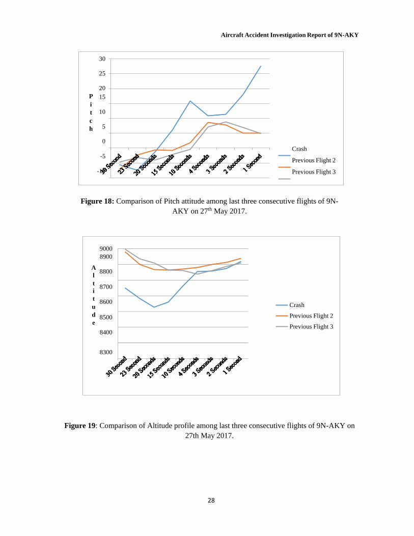
27th May 2017 Figure 19: Comparison of Altitude profile among last three consecutive flights of 9N-AKY
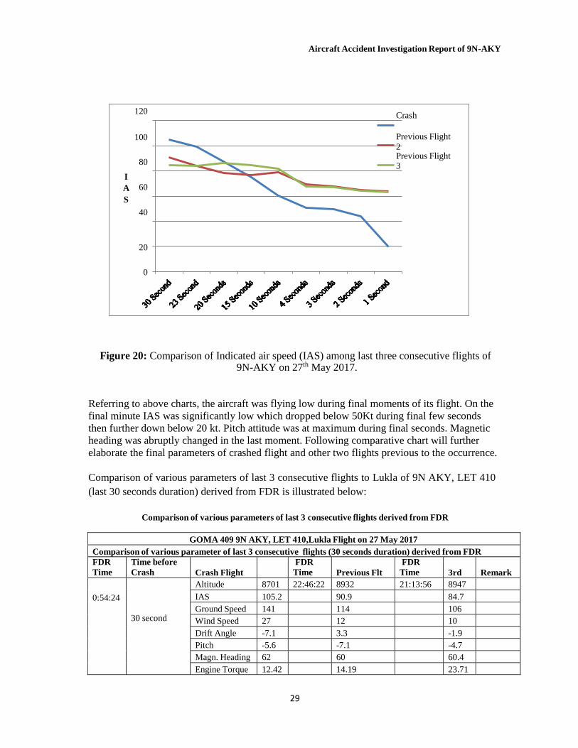
on 27th May 2017 Figure 20: Comparison of Indicated air speed (IAS) among last three consecutive flights of
9N-AKY on 27th May 2017 Figure 21: Power curve Figure 22: The track on the right-hand side was followed by ill-fated GOMA AIR aircraft
9N-AKY Figure 23: Final flight path of Goma Air 409 along with time stamp of critical CVR records
synchronized
Aircraft Accident Investigation Report of 9N-AKY
9
List of Appendix
Appendix I Kathmandu (VNKT) METAR from 0620 to 1220 on the day of accident. Appendix II Report on prevailing weather conditions over Eastern Nepal Appendix III ATC/Pilot VHF Transcript Appendix IV CVR Transcript Appendix V FDR Data Appendix VI Crash Site Photos
Aircraft Accident Investigation Report of 9N-AKY
1
Abbreviations and Definitions
ADF Aircraft Direction Finder AFIS Aerodrome Flight Information System AHRS Air Data Altitude Heading Reference System AIP Aeronautical Information Publication AMSL Above Mean Sea Level AOC Air Operator’s Certificate AOCR Air Operator’s Certificate Regulation PAPI Precision Approach Path Indicator ATC Air Traffic Controller ATS Air Traffic Service B.S. Bikram Sambat CAAN Civil Aviation Authority of Nepal CAM Cockpit Area Microphone CFIT Controlled Flight Into Terrian CG Center of Gravity CRM Crew Resource Management CSN Cycle Since New CVR Cockpit Voice Recorder CWD central warning display CWD central warning display DHM Department of Hydrology and Metrology DME Distance Measurement Equipment EFIS Electronic Flight Instrument System EGPWS Enhanced Ground Proximity Warning System ELU Engine Limiter Unit FDM Flight Data Monitoring Fig. Figure FO First Officer FOR Fight Operation Requirement Ft. Feet GPS Global Positioning System HF High Frequency IAS Indicated air speed IFR Instrument Flight Rule IOM. Institute of Medicine KTM Kathmandu KW Kilo-Watt LH Left Hand MADRAS Modular Airborne Data Recording Acquisition System MOU Memorandum of Understanding MRO Maintenance Repair Overhaul NAV Navigation NCAR National Civil Aviation Requirements PIC Pilot In Command Pvt. Ltd. Private Limited QNH Pressure Setting to Indicate Elevation above Mean Sea Level RH Right Hand RPM Revolution Per Minute
Aircraft Accident Investigation Report of 9N-AKY
1
RWY Run Way SALM Start and Limiter Module SATCOM Satellite Communication SMS Safety Management System SOP Standard Operation Procedure STOL Short Takeoff and Landing TCAS Traffic Alert and Collision Avoidance System TIA Tribhuvan International Airport TSN Time since New TSO Time since Overhaul UTC Coordinated Universal Time VAGS Visual Augmented Guidance System VFR Visual Flight Rule VHF Very High Frequency VMC Visual Meteorological Condition VOR VHF Omni-directional Radio Range WNI Weather News International
Aircraft Accident Investigation Report of 9N-AKY
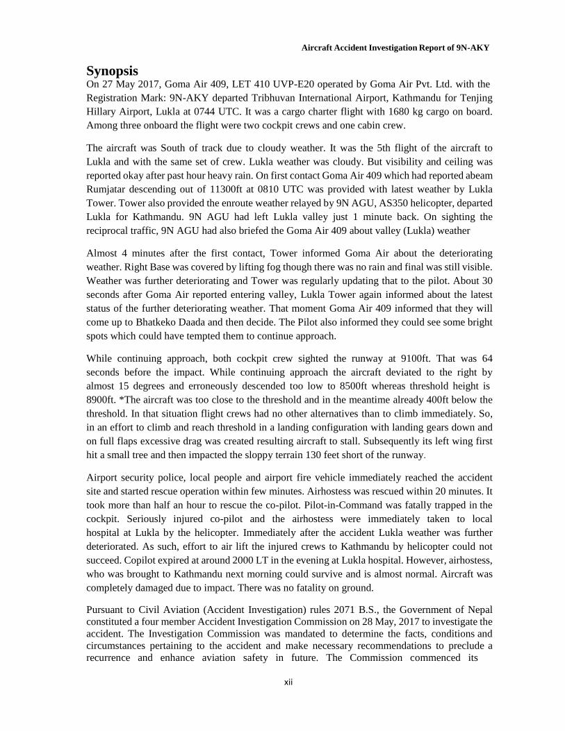
Synopsis On 27 May 2017, Goma Air 409, LET 410 UVP-E20 operated by Goma Air Pvt. Ltd. with the Registration Mark: 9N-AKY departed Tribhuvan International Airport, Kathmandu for Tenjing Hillary Airport, Lukla at 0744 UTC. It was a cargo charter flight with 1680 kg cargo on board. Among three onboard the flight were two cockpit crews and one cabin crew.
The aircraft was South of track due to cloudy weather. It was the 5th flight of the aircraft to Lukla and with the same set of crew. Lukla weather was cloudy. But visibility and ceiling was reported okay after past hour heavy rain. On first contact Goma Air 409 which had reported abeam Rumjatar descending out of 11300ft at 0810 UTC was provided with latest weather by Lukla Tower. Tower also provided the enroute weather relayed by 9N AGU, AS350 helicopter, departed Lukla for Kathmandu. 9N AGU had left Lukla valley just 1 minute back. On sighting the reciprocal traffic, 9N AGU had also briefed the Goma Air 409 about valley (Lukla) weather
Almost 4 minutes after the first contact, Tower informed Goma Air about the deteriorating weather. Right Base was covered by lifting fog though there was no rain and final was still visible. Weather was further deteriorating and Tower was regularly updating that to the pilot. About 30 seconds after Goma Air reported entering valley, Lukla Tower again informed about the latest status of the further deteriorating weather. That moment Goma Air 409 informed that they will come up to Bhatkeko Daada and then decide. The Pilot also informed they could see some bright spots which could have tempted them to continue approach.
While continuing approach, both cockpit crew sighted the runway at 9100ft. That was 64 seconds before the impact. While continuing approach the aircraft deviated to the right by almost 15 degrees and erroneously descended too low to 8500ft whereas threshold height is 8900ft. *The aircraft was too close to the threshold and in the meantime already 400ft below the threshold. In that situation flight crews had no other alternatives than to climb immediately. So, in an effort to climb and reach threshold in a landing configuration with landing gears down and on full flaps excessive drag was created resulting aircraft to stall. Subsequently its left wing first hit a small tree and then impacted the sloppy terrain 130 feet short of the runway.
Airport security police, local people and airport fire vehicle immediately reached the accident site and started rescue operation within few minutes. Airhostess was rescued within 20 minutes. It took more than half an hour to rescue the co-pilot. Pilot-in-Command was fatally trapped in the cockpit. Seriously injured co-pilot and the airhostess were immediately taken to local hospital at Lukla by the helicopter. Immediately after the accident Lukla weather was further deteriorated. As such, effort to air lift the injured crews to Kathmandu by helicopter could not succeed. Copilot expired at around 2000 LT in the evening at Lukla hospital. However, airhostess, who was brought to Kathmandu next morning could survive and is almost normal. Aircraft was completely damaged due to impact. There was no fatality on ground.
Pursuant to Civil Aviation (Accident Investigation) rules 2071 B.S., the Government of Nepal constituted a four member Accident Investigation Commission on 28 May, 2017 to investigate the accident. The Investigation Commission was mandated to determine the facts, conditions and circumstances pertaining to the accident and make necessary recommendations to preclude a recurrence and enhance aviation safety in future. The Commission commenced its
xii
Aircraft Accident Investigation Report of 9N-AKY
investigation task formally on 29 May, 2017. The Commission concludes that the probable cause of this accident was aircraft stall as a result of excessive drag created by sudden increase in angle of attack of the aircraft supplemented by low speed (below Vref) in an attempt to initiate immediate climb on a landing configuration (full flap and landing gear down) warranted by the critical situation of the final phase of flight.
The Commission has made twenty (20) safety recommendations for the further enhancement to aviation safety and to prevent such accidents in future.
*8900 ft is on Kathmandu QNH whereas as per AIP it is 9200
xiii
Aircraft Accident Investigation Report of 9N-AKY
14
1. Factual Information
1.1 History of the Flight
On May 27, 2017 9N-AKY, LET 410 UVP-E20 of Goma Air (now Summit Air), a domestic carrier of Nepal had a published program to operate 5 flights to Lukla from Kathmandu. The first flight departed Kathmandu at 0026 UTC. By the time 0647 UTC they had completed 4 flights. The fifth and the last flight departed Kathmandu at 0744 UTC for Lukla as call sign Goma Air 409. Goma Air 409 was the cargo flight carrying 1680 kg cargo for Lukla. There were two cockpit crews, one cabin crew and no passengers on board the flight. All 5 flights were operated by same set of crew. The details of the unfortunate flight were as follows:
Aerodrome of Departure: Tribhuvan International Airport, Kathmandu
EOBT: 0530UTC Destination Aerodrome: Lukla
En-route Altitude: 11500ft
Estimated Time of Arrival Lukla : 0821 UTC
1stAlternate Aerodrome: Ramechhap
2nd Alternate: Phaplu Endurance: 02:30 HRS
POB (Or, Crew): 03 Crew Members
Equipments: SD/N
Cargo: 1680 kg, Pax: Nil
Flight Rule: VFR
Table 1: Details of the ill-fated flight of 9N- AKY on 27th May, 2017.
It was pre-monsoon period. Lukla weather on that particular day was cloudy since morning. But ceiling and visibility were reported OK. However, CCTV footage shows rapidly deteriorating weather condition before and after the crash. Automatic VHF recorder of Lukla Tower and CVR recording showed Tower was regularly updating pilots of deteriorating weather.
All the pre-and post-departure procedure of the flight was completed in normal manner. Before departure from Kathmandu Pilots were found to have obtained latest weather of Lukla, Phaplu and Rumjatar. PIC decided to remain south of track to avoid the terrain and cloud. When Goma 409 was about 11 miles East from Kathmandu they were informed that Lukla was having heavy rain and airport closed. By that time air traffic congestion in TIA was slowly developing. Traffics were holding in the air and in the ground as well. So Goma 409 continued for Lukla. However, after crossing 26 miles from Kathmandu, they were again informed that the rain had ceased and airport was open.
An AS350 helicopter, 9N AGU which departed Lukla at 0803 UTC for Kathmandu had reported unstable wind on final Runway 06. Enroute weather reported by 9N AGU upon request of Lukla Tower was good beyond the Lukla valley. However, it was apprehended that for fixed wing, weather might be difficult to enter valley. Lukla Tower relayed all available information when Goma Air 409 had first established contact at time 0810 UTC. Later, Goma Air and 9N AGY, two reciprocal traffics were also in contact each other. 9N AGY relayed the actual weather status to GOMA AIR.
Lukla valley's ceiling and visibility was OK for VFR until 0812UTC ( 6 minutes before crash). Weather started to deteriorate very fast. Mountain Ridges were visible through thin layer of
Aircraft Accident Investigation Report of 9N-AKY
15
foggy cloud until 0814 UTC. After one minute (approx.) Right Base for Runway 06, was covered up and cloud from left base was moving towards final. Duty ATS Officer of Lukla Tower was regularly up dating pilots about deteriorating weather condition. However, Tower was found to be failed to close the runway as per SOP in spite of rapidly deteriorating weather. Pilots ventured to continue though the weather was marginal.
Aircraft reported entering valley at 0816. CVR record showed that First Officer sighted the runway at 0817 (64 seconds before the impact). Instantly PIC acknowledged he had also the runway in sight. Aircraft was at 9100 ft(approx.) when the cockpit crews sighted the runway. It maintained 9000 feet (approx.) for further 21 seconds. At time 0817:12i.e. 48 seconds before the impact Tower gave the latest wind as Westerly 04 knots and runway was clear. PIC was still in doubt and asked whether there was rain. Upon confirmation of having no rain from the Tower the aircraft started to descend further. The PIC, who was also the PF, found to have lost situational awareness deviated to the right with continued descend. At 0817:35 (25 seconds before impact) when the flight was descending through 8650ft First Officer warned PIC that they were too low. PIC did not respond the F/O's call-out and continued descend. On reaching 8500ft. F/O again warned PIC in panic. Then PIC asked in panic where the runway was. F/O directed towards the runway. But it was already too low and too late. There was initially two short stall warning sound. Then a continuous stall warning sounded till the impact, which lasted for 13 seconds. The last words in CVR records was "w]/ gtfg " (Do not pull too much).
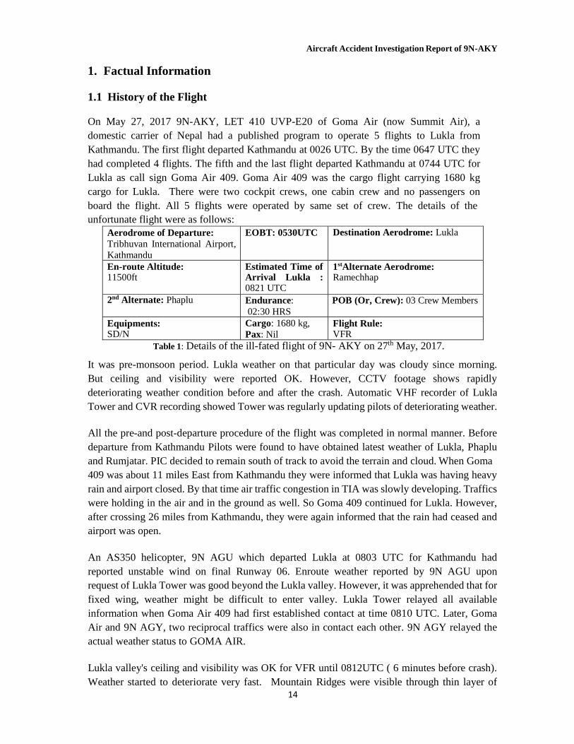
Abrupt change in aircraft attitude in an attempt to climb and reach threshold height at 8900ft. (on Kathmandu QNH) in a landing configuration, with landing gears down and on full flaps, created excessive drag resulting the aircraft to stall. Subsequently, its left wing first hit a small tree branch 180ft. short of the threshold. Then impacted the sloppy terrain 100ft. short of the runway.After the crash aircraft engine was reported to be running for about a minute. But there was no post-crash fire. Aircraft was totally damaged by the impact.
Crash site:
Figure 1 : Geographical reference of the crash site: 27416N, 864343 E Elevation: 8800 feet AMSL
Point of Ultimate Impact
Aircraft Accident Investigation Report of 9N-AKY
16
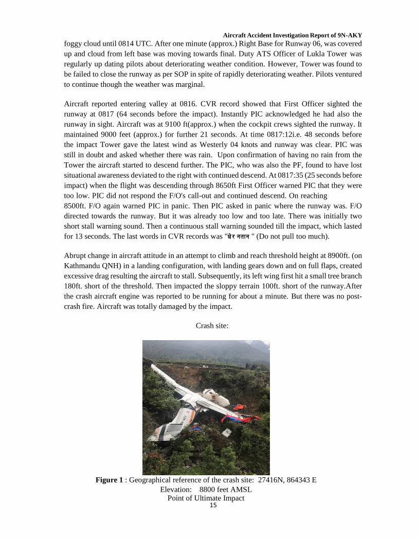
Figure 2 : Point of ultimate impact
1.2 Injuries to Persons Injuries to persons
Injuries Crew Passengers Others Fatal 2 NIL - Serious 1 - - Minor/None - - -
Table 2: Injuries to persons
The detailed descriptions of injuries of the individual bodies are given in Appendix. 1.3 Damage to Aircraft
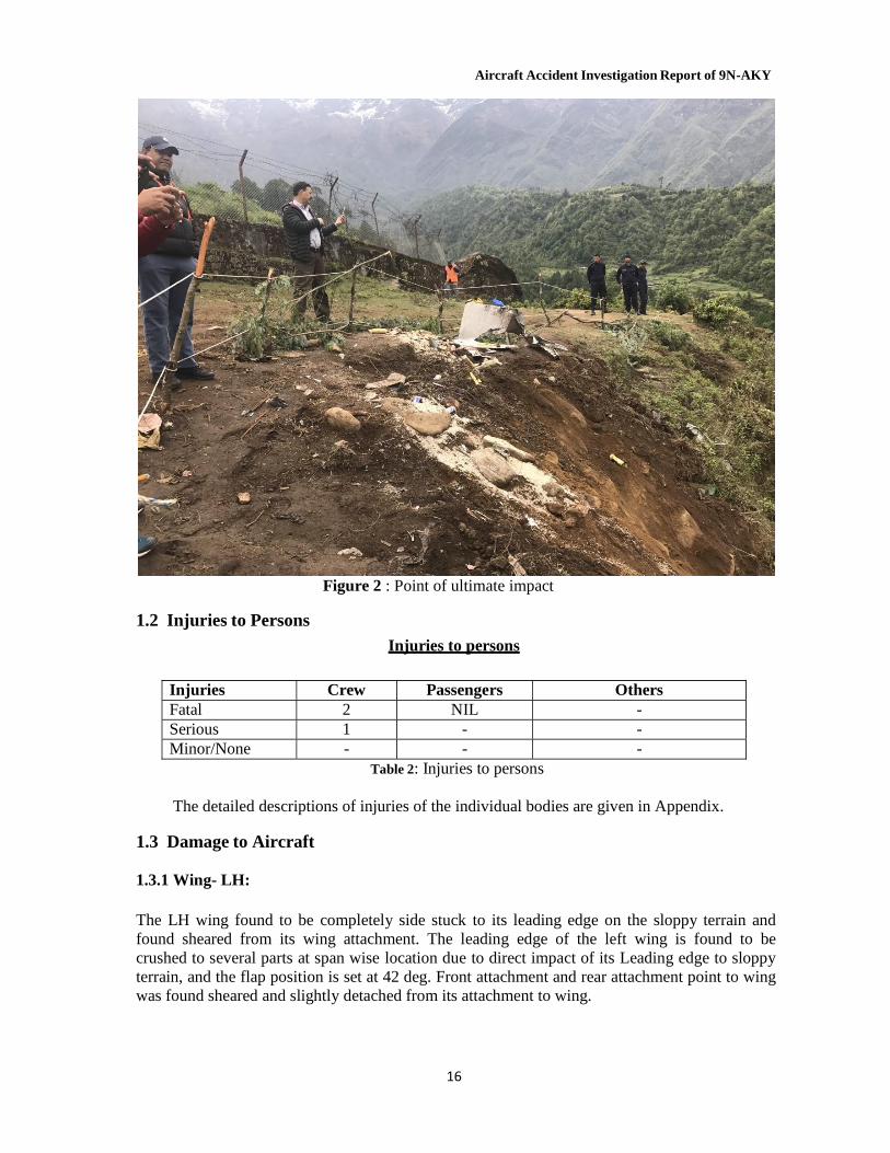
1.3.1 Wing- LH:
The LH wing found to be completely side stuck to its leading edge on the sloppy terrain and found sheared from its wing attachment. The leading edge of the left wing is found to be crushed to several parts at span wise location due to direct impact of its Leading edge to sloppy terrain, and the flap position is set at 42 deg. Front attachment and rear attachment point to wing was found sheared and slightly detached from its attachment to wing.
Aircraft Accident Investigation Report of 9N-AKY
17
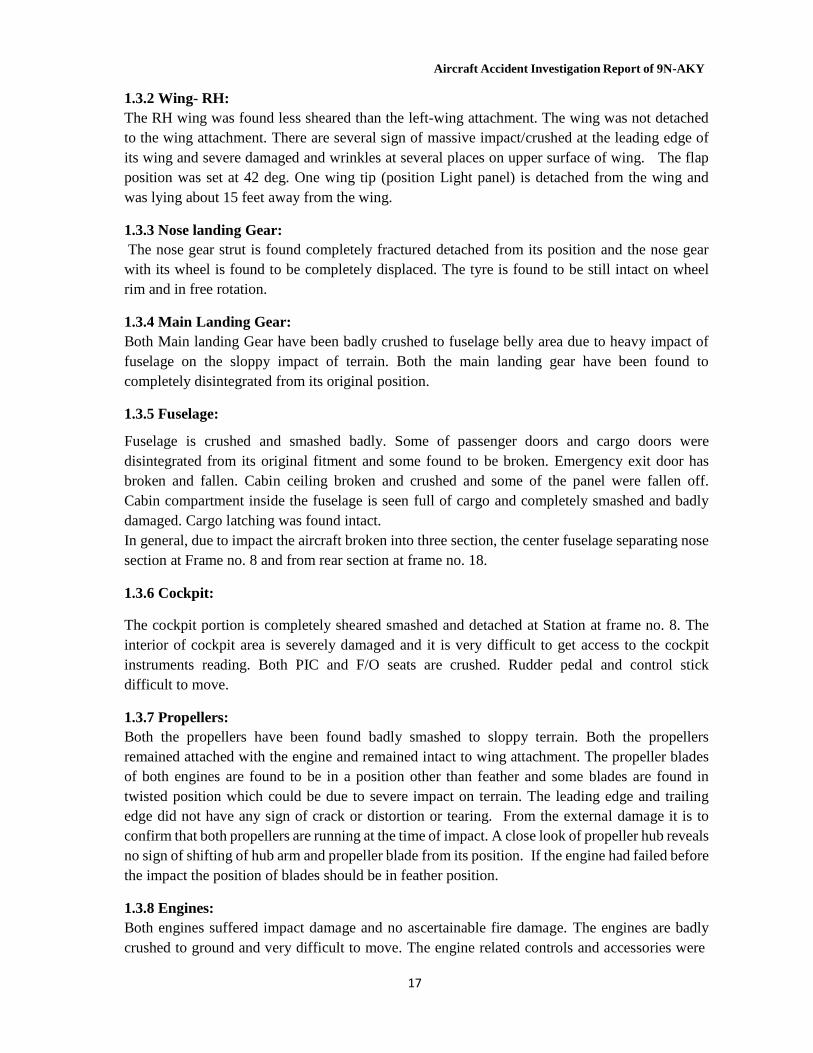
1.3.2 Wing- RH: The RH wing was found less sheared than the left-wing attachment. The wing was not detached to the wing attachment. There are several sign of massive impact/crushed at the leading edge of its wing and severe damaged and wrinkles at several places on upper surface of wing. The flap position was set at 42 deg. One wing tip (position Light panel) is detached from the wing and was lying about 15 feet away from the wing.
1.3.3 Nose landing Gear: The nose gear strut is found completely fractured detached from its position and the nose gear with its wheel is found to be completely displaced. The tyre is found to be still intact on wheel rim and in free rotation.
1.3.4 Main Landing Gear: Both Main landing Gear have been badly crushed to fuselage belly area due to heavy impact of fuselage on the sloppy impact of terrain. Both the main landing gear have been found to completely disintegrated from its original position.
1.3.5 Fuselage:
Fuselage is crushed and smashed badly. Some of passenger doors and cargo doors were disintegrated from its original fitment and some found to be broken. Emergency exit door has broken and fallen. Cabin ceiling broken and crushed and some of the panel were fallen off. Cabin compartment inside the fuselage is seen full of cargo and completely smashed and badly damaged. Cargo latching was found intact. In general, due to impact the aircraft broken into three section, the center fuselage separating nose section at Frame no. 8 and from rear section at frame no. 18.
1.3.6 Cockpit:
The cockpit portion is completely sheared smashed and detached at Station at frame no. 8. The interior of cockpit area is severely damaged and it is very difficult to get access to the cockpit instruments reading. Both PIC and F/O seats are crushed. Rudder pedal and control stick difficult to move.
1.3.7 Propellers: Both the propellers have been found badly smashed to sloppy terrain. Both the propellers remained attached with the engine and remained intact to wing attachment. The propeller blades of both engines are found to be in a position other than feather and some blades are found in twisted position which could be due to severe impact on terrain. The leading edge and trailing edge did not have any sign of crack or distortion or tearing. From the external damage it is to confirm that both propellers are running at the time of impact. A close look of propeller hub reveals no sign of shifting of hub arm and propeller blade from its position. If the engine had failed before the impact the position of blades should be in feather position.
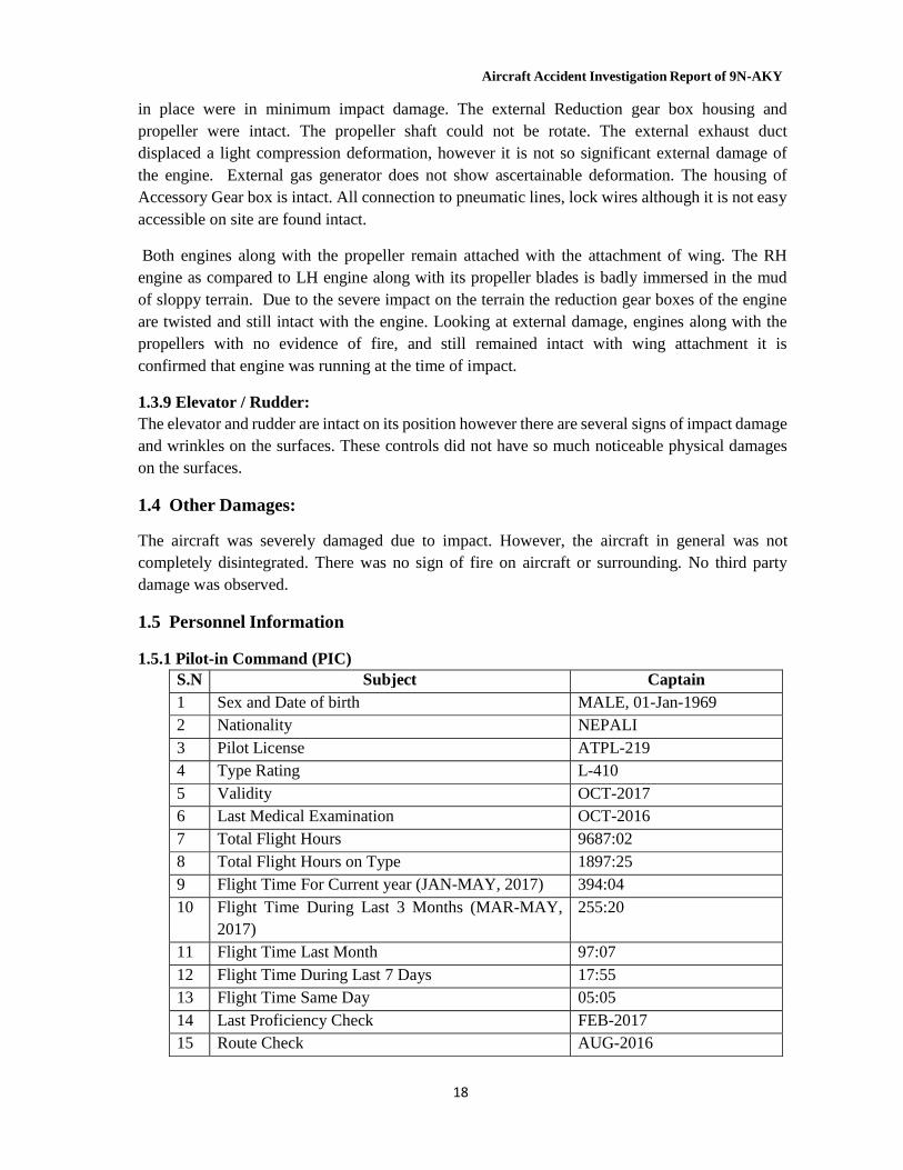
1.3.8 Engines: Both engines suffered impact damage and no ascertainable fire damage. The engines are badly crushed to ground and very difficult to move. The engine related controls and accessories were
Aircraft Accident Investigation Report of 9N-AKY
18
in place were in minimum impact damage. The external Reduction gear box housing and propeller were intact. The propeller shaft could not be rotate. The external exhaust duct displaced a light compression deformation, however it is not so significant external damage of the engine. External gas generator does not show ascertainable deformation. The housing of Accessory Gear box is intact. All connection to pneumatic lines, lock wires although it is not easy accessible on site are found intact.
Both engines along with the propeller remain attached with the attachment of wing. The RH engine as compared to LH engine along with its propeller blades is badly immersed in the mud of sloppy terrain. Due to the severe impact on the terrain the reduction gear boxes of the engine are twisted and still intact with the engine. Looking at external damage, engines along with the propellers with no evidence of fire, and still remained intact with wing attachment it is confirmed that engine was running at the time of impact.
1.3.9 Elevator / Rudder: The elevator and rudder are intact on its position however there are several signs of impact damage and wrinkles on the surfaces. These controls did not have so much noticeable physical damages on the surfaces.
1.4 Other Damages: The aircraft was severely damaged due to impact. However, the aircraft in general was not completely disintegrated. There was no sign of fire on aircraft or surrounding. No third party damage was observed.
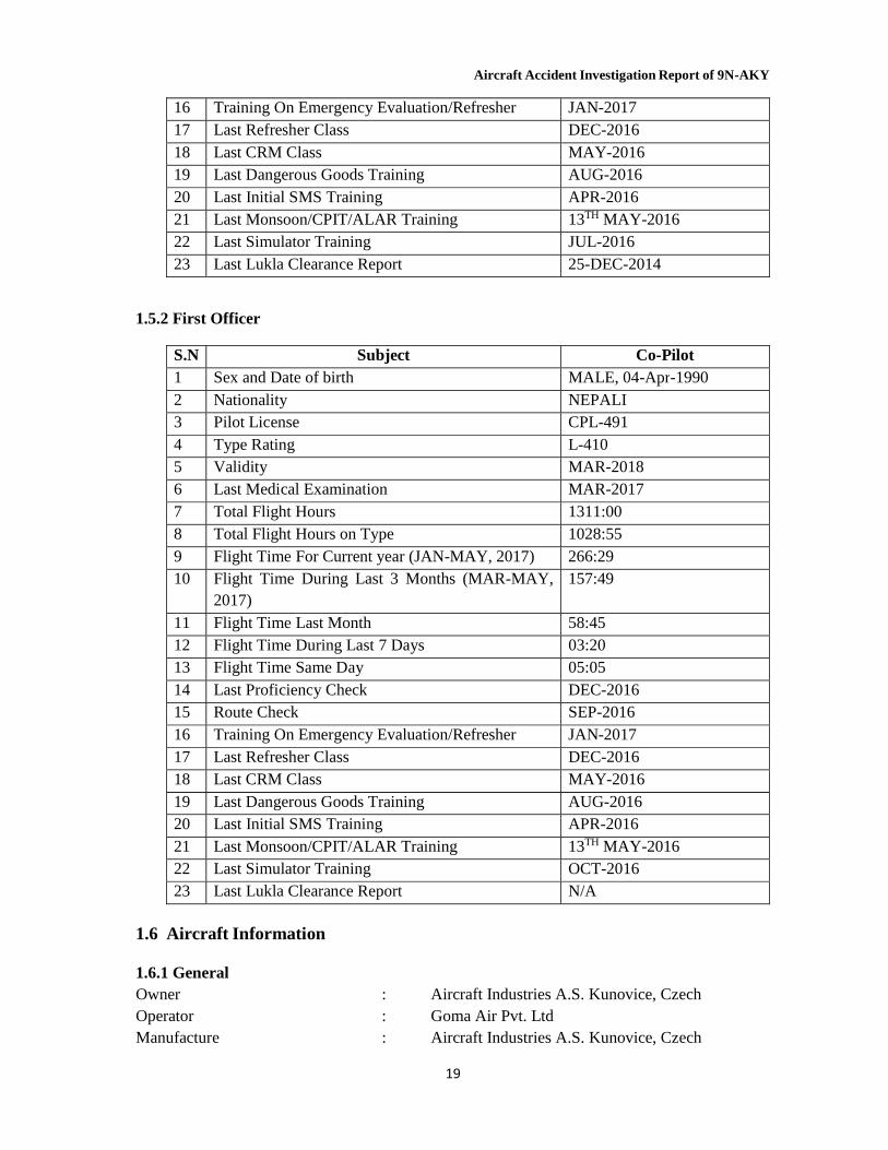
1.5 Personnel Information 1.5.1 Pilot-in Command (PIC)
S.N Subject Captain 1 Sex and Date of birth MALE, 01-Jan-1969 2 Nationality NEPALI 3 Pilot License ATPL-219 4 Type Rating L-410 5 Validity OCT-2017 6 Last Medical Examination OCT-2016 7 Total Flight Hours 9687:02 8 Total Flight Hours on Type 1897:25 9 Flight Time For Current year (JAN-MAY, 2017) 394:04 10 Flight Time During Last 3 Months (MAR-MAY,
2017) 255:20
11 Flight Time Last Month 97:07 12 Flight Time During Last 7 Days 17:55 13 Flight Time Same Day 05:05 14 Last Proficiency Check FEB-2017 15 Route Check AUG-2016
Aircraft Accident Investigation Report of 9N-AKY
19
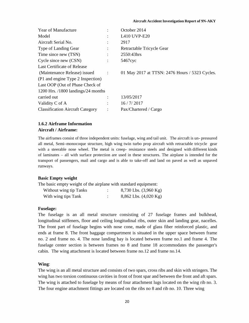
16 Training On Emergency Evaluation/Refresher JAN-2017 17 Last Refresher Class DEC-2016 18 Last CRM Class MAY-2016 19 Last Dangerous Goods Training AUG-2016 20 Last Initial SMS Training APR-2016 21 Last Monsoon/CPIT/ALAR Training 13TH MAY-2016 22 Last Simulator Training JUL-2016 23 Last Lukla Clearance Report 25-DEC-2014
1.5.2 First Officer
S.N Subject Co-Pilot 1 Sex and Date of birth MALE, 04-Apr-1990 2 Nationality NEPALI 3 Pilot License CPL-491 4 Type Rating L-410 5 Validity MAR-2018 6 Last Medical Examination MAR-2017 7 Total Flight Hours 1311:00 8 Total Flight Hours on Type 1028:55 9 Flight Time For Current year (JAN-MAY, 2017) 266:29 10 Flight Time During Last 3 Months (MAR-MAY,
2017) 157:49
11 Flight Time Last Month 58:45 12 Flight Time During Last 7 Days 03:20 13 Flight Time Same Day 05:05 14 Last Proficiency Check DEC-2016 15 Route Check SEP-2016 16 Training On Emergency Evaluation/Refresher JAN-2017 17 Last Refresher Class DEC-2016 18 Last CRM Class MAY-2016 19 Last Dangerous Goods Training AUG-2016 20 Last Initial SMS Training APR-2016 21 Last Monsoon/CPIT/ALAR Training 13TH MAY-2016 22 Last Simulator Training OCT-2016 23 Last Lukla Clearance Report N/A
1.6 Aircraft Information
1.6.1 General Owner : Aircraft Industries A.S. Kunovice, Czech Operator : Goma Air Pvt. Ltd Manufacture : Aircraft Industries A.S. Kunovice, Czech
Aircraft Accident Investigation Report of 9N-AKY
20
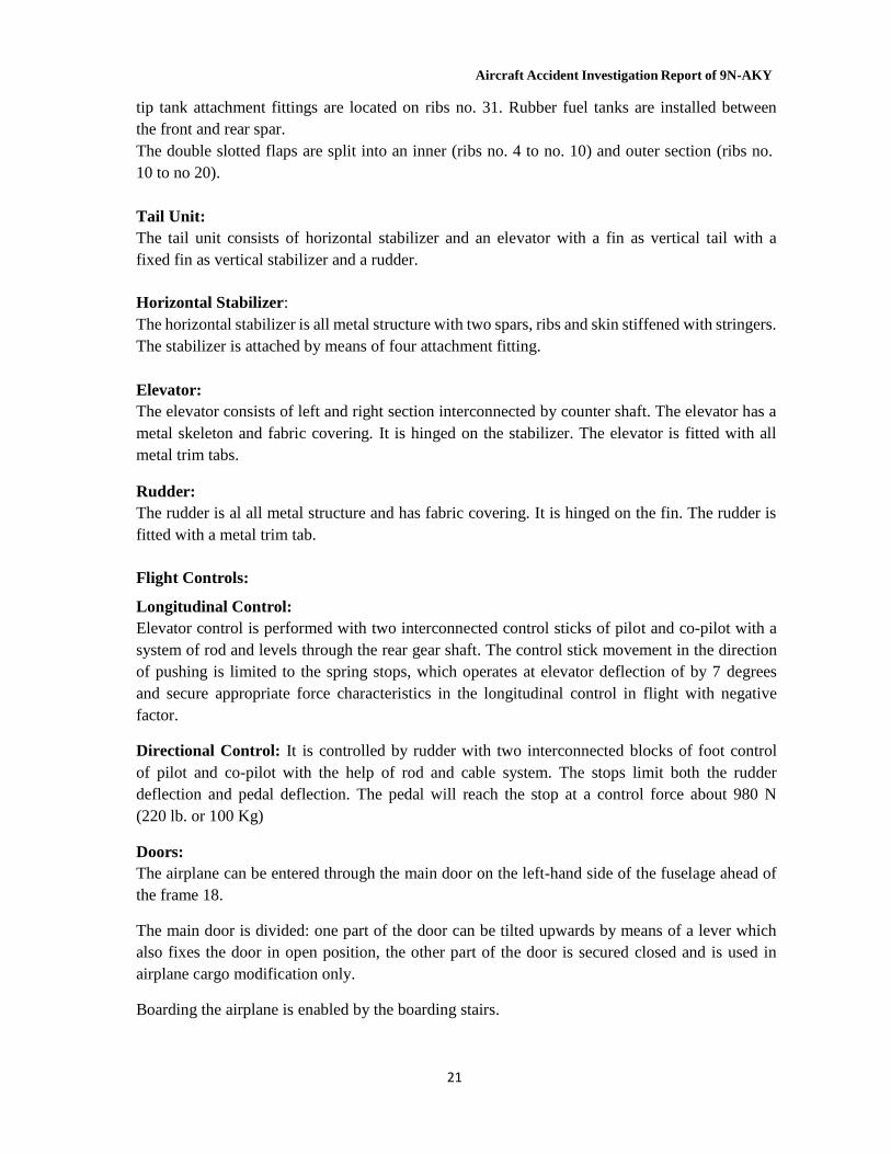
Year of Manufacture : October 2014 Model : L410 UVP-E20 Aircraft Serial No. : 2917 Type of Landing Gear : Retractable Tricycle Gear Time since new (TSN) : 2550:43hrs Cycle since new (CSN) : 5467cyc Last Certificate of Release (Maintenance Release) issued : 01 May 2017 at TTSN: 2476 Hours / 5323 Cycles. (P1 and engine Type 2 Inspection) Last OOP (Out of Phase Check of 1200 Hrs. /1800 landings/24 months carried out : 13/05/2017 Validity C of A : 16 / 7/ 2017 Classification Aircraft Category : Pax/Chartered / Cargo
1.6.2 Airframe Information Aircraft / Airframe:
The airframes consist of three independent units: fuselage, wing and tail unit. The aircraft is un- pressured all metal, Semi–monocoque structure, high wing twin turbo prop aircraft with retractable tricycle gear with a steerable nose wheel. The metal is creep- resistance steels and designed with different kinds of laminates – all with surface protection are used in these structures. The airplane is intended for the transport of passengers, mail and cargo and is able to take-off and land on paved as well as unpaved runways.
Basic Empty weight The basic empty weight of the airplane with standard equipment:
Without wing tip Tanks : 8,730 Lbs. (3,960 Kg) With wing tips Tank : 8,862 Lbs. (4,020 Kg)
Fuselage: The fuselage is an all metal structure consisting of 27 fuselage frames and bulkhead, longitudinal stiffeners, floor and ceiling longitudinal ribs, outer skin and landing gear, nacelles. The front part of fuselage begins with nose cone, made of glass fiber reinforced plastic, and ends at frame 8. The front baggage compartment is situated in the upper space between frame no. 2 and frame no. 4. The nose landing bay is located between frame no.1 and frame 4. The fuselage center section is between frames no 8 and frame 18 accommodates the passenger's cabin. The wing attachment is located between frame no.12 and frame no.14.
Wing: The wing is an all metal structure and consists of two spars, cross ribs and skin with stringers. The wing has two torsion continuous cavities in front of front spar and between the front and aft spars. The wing is attached to fuselage by means of four attachment lugs located on the wing rib no. 3. The four engine attachment fittings are located on the ribs no 8 and rib no. 10. Three wing
Aircraft Accident Investigation Report of 9N-AKY
21
tip tank attachment fittings are located on ribs no. 31. Rubber fuel tanks are installed between the front and rear spar. The double slotted flaps are split into an inner (ribs no. 4 to no. 10) and outer section (ribs no. 10 to no 20).
Tail Unit: The tail unit consists of horizontal stabilizer and an elevator with a fin as vertical tail with a fixed fin as vertical stabilizer and a rudder.
Horizontal Stabilizer: The horizontal stabilizer is all metal structure with two spars, ribs and skin stiffened with stringers. The stabilizer is attached by means of four attachment fitting.
Elevator: The elevator consists of left and right section interconnected by counter shaft. The elevator has a metal skeleton and fabric covering. It is hinged on the stabilizer. The elevator is fitted with all metal trim tabs.
Rudder: The rudder is al all metal structure and has fabric covering. It is hinged on the fin. The rudder is fitted with a metal trim tab.
Flight Controls:
Longitudinal Control: Elevator control is performed with two interconnected control sticks of pilot and co-pilot with a system of rod and levels through the rear gear shaft. The control stick movement in the direction of pushing is limited to the spring stops, which operates at elevator deflection of by 7 degrees and secure appropriate force characteristics in the longitudinal control in flight with negative factor.
Directional Control: It is controlled by rudder with two interconnected blocks of foot control of pilot and co-pilot with the help of rod and cable system. The stops limit both the rudder deflection and pedal deflection. The pedal will reach the stop at a control force about 980 N (220 lb. or 100 Kg)
Doors: The airplane can be entered through the main door on the left-hand side of the fuselage ahead of the frame 18.
The main door is divided: one part of the door can be tilted upwards by means of a lever which also fixes the door in open position, the other part of the door is secured closed and is used in airplane cargo modification only.
Boarding the airplane is enabled by the boarding stairs.
Aircraft Accident Investigation Report of 9N-AKY
22
Emergency exists in the passenger compartment are located on the LH and RH side of the passenger compartment between frame no. 13 and 14. An emergency exit door (between frame 6 and 8) is also located on the right-hand side of the nose section fuselage.
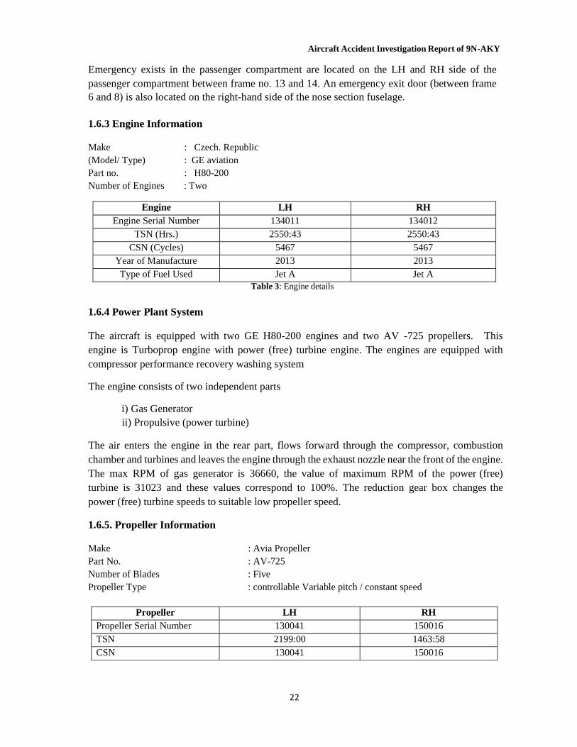
1.6.3 Engine Information
Make : Czech. Republic (Model/ Type) : GE aviation Part no. : H80-200 Number of Engines : Two
Engine LH RH
Engine Serial Number 134011 134012 TSN (Hrs.) 2550:43 2550:43
CSN (Cycles) 5467 5467 Year of Manufacture 2013 2013 Type of Fuel Used Jet A Jet A
Table 3: Engine details
1.6.4 Power Plant System
The aircraft is equipped with two GE H80-200 engines and two AV -725 propellers. This engine is Turboprop engine with power (free) turbine engine. The engines are equipped with compressor performance recovery washing system
The engine consists of two independent parts
i) Gas Generator ii) Propulsive (power turbine)
The air enters the engine in the rear part, flows forward through the compressor, combustion chamber and turbines and leaves the engine through the exhaust nozzle near the front of the engine. The max RPM of gas generator is 36660, the value of maximum RPM of the power (free) turbine is 31023 and these values correspond to 100%. The reduction gear box changes the power (free) turbine speeds to suitable low propeller speed.
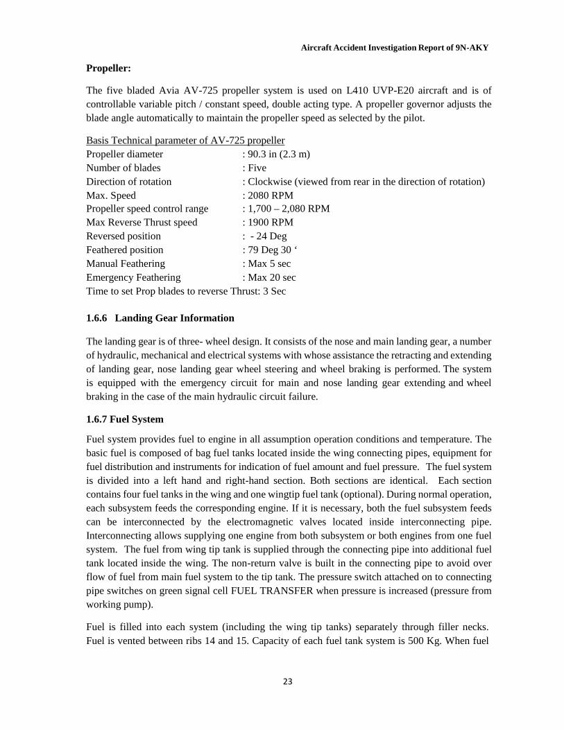
1.6.5. Propeller Information
Make : Avia Propeller Part No. : AV-725 Number of Blades : Five Propeller Type : controllable Variable pitch / constant speed
Propeller LH RH
Propeller Serial Number 130041 150016 TSN 2199:00 1463:58 CSN 130041 150016
Aircraft Accident Investigation Report of 9N-AKY
23
Propeller: The five bladed Avia AV-725 propeller system is used on L410 UVP-E20 aircraft and is of controllable variable pitch / constant speed, double acting type. A propeller governor adjusts the blade angle automatically to maintain the propeller speed as selected by the pilot.
Basis Technical parameter of AV-725 propeller Propeller diameter : 90.3 in (2.3 m) Number of blades : Five Direction of rotation : Clockwise (viewed from rear in the direction of rotation) Max. Speed : 2080 RPM Propeller speed control range : 1,700 – 2,080 RPM Max Reverse Thrust speed : 1900 RPM Reversed position : - 24 Deg Feathered position : 79 Deg 30 ‘ Manual Feathering : Max 5 sec Emergency Feathering : Max 20 sec Time to set Prop blades to reverse Thrust: 3 Sec
1.6.6 Landing Gear Information
The landing gear is of three- wheel design. It consists of the nose and main landing gear, a number of hydraulic, mechanical and electrical systems with whose assistance the retracting and extending of landing gear, nose landing gear wheel steering and wheel braking is performed. The system is equipped with the emergency circuit for main and nose landing gear extending and wheel braking in the case of the main hydraulic circuit failure.
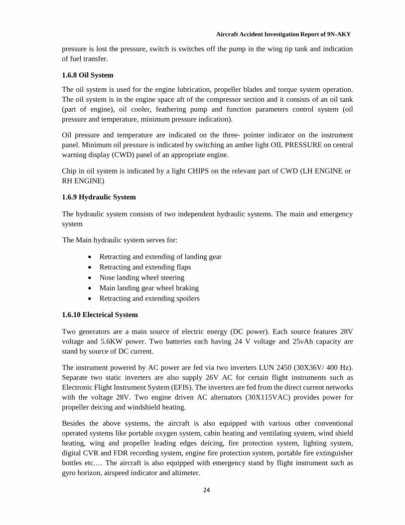
1.6.7 Fuel System
Fuel system provides fuel to engine in all assumption operation conditions and temperature. The basic fuel is composed of bag fuel tanks located inside the wing connecting pipes, equipment for fuel distribution and instruments for indication of fuel amount and fuel pressure. The fuel system is divided into a left hand and right-hand section. Both sections are identical. Each section contains four fuel tanks in the wing and one wingtip fuel tank (optional). During normal operation, each subsystem feeds the corresponding engine. If it is necessary, both the fuel subsystem feeds can be interconnected by the electromagnetic valves located inside interconnecting pipe. Interconnecting allows supplying one engine from both subsystem or both engines from one fuel system. The fuel from wing tip tank is supplied through the connecting pipe into additional fuel tank located inside the wing. The non-return valve is built in the connecting pipe to avoid over flow of fuel from main fuel system to the tip tank. The pressure switch attached on to connecting pipe switches on green signal cell FUEL TRANSFER when pressure is increased (pressure from working pump).
Fuel is filled into each system (including the wing tip tanks) separately through filler necks. Fuel is vented between ribs 14 and 15. Capacity of each fuel tank system is 500 Kg. When fuel
Aircraft Accident Investigation Report of 9N-AKY
24
pressure is lost the pressure, switch is switches off the pump in the wing tip tank and indication of fuel transfer.
1.6.8 Oil System
The oil system is used for the engine lubrication, propeller blades and torque system operation. The oil system is in the engine space aft of the compressor section and it consists of an oil tank (part of engine), oil cooler, feathering pump and function parameters control system (oil pressure and temperature, minimum pressure indication).
Oil pressure and temperature are indicated on the three- pointer indicator on the instrument panel. Minimum oil pressure is indicated by switching an amber light OIL PRESSURE on central warning display (CWD) panel of an appropriate engine.
Chip in oil system is indicated by a light CHIPS on the relevant part of CWD (LH ENGINE or RH ENGINE)
1.6.9 Hydraulic System
The hydraulic system consists of two independent hydraulic systems. The main and emergency system
The Main hydraulic system serves for:
Retracting and extending of landing gear
Retracting and extending flaps
Nose landing wheel steering
Main landing gear wheel braking
Retracting and extending spoilers 1.6.10 Electrical System
Two generators are a main source of electric energy (DC power). Each source features 28V voltage and 5.6KW power. Two batteries each having 24 V voltage and 25vAh capacity are stand by source of DC current.
The instrument powered by AC power are fed via two inverters LUN 2450 (30X36V/ 400 Hz). Separate two static inverters are also supply 26V AC for certain flight instruments such as Electronic Flight Instrument System (EFIS). The inverters are fed from the direct current networks with the voltage 28V. Two engine driven AC alternators (30X115VAC) provides power for propeller deicing and windshield heating.
Besides the above systems, the aircraft is also equipped with various other conventional operated systems like portable oxygen system, cabin heating and ventilating system, wind shield heating, wing and propeller leading edges deicing, fire protection system, lighting system, digital CVR and FDR recording system, engine fire protection system, portable fire extinguisher bottles etc.… The aircraft is also equipped with emergency stand by flight instrument such as gyro horizon, airspeed indicator and altimeter.
Aircraft Accident Investigation Report of 9N-AKY
25
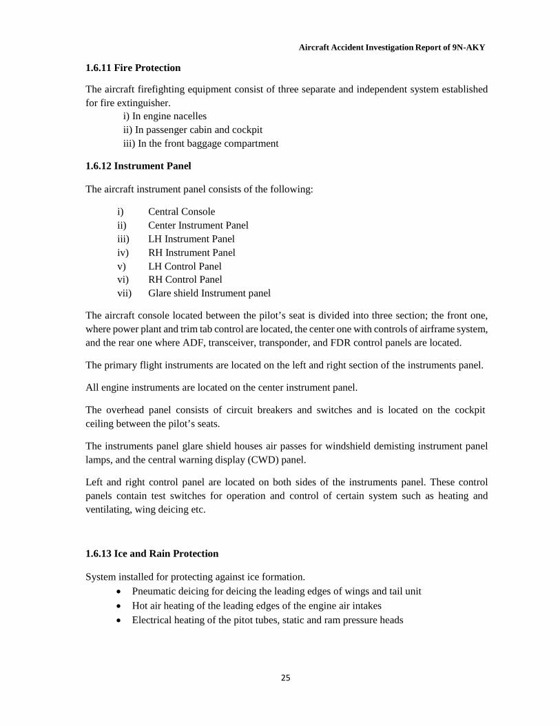
1.6.11 Fire Protection The aircraft firefighting equipment consist of three separate and independent system established for fire extinguisher.
i) In engine nacelles ii) In passenger cabin and cockpit iii) In the front baggage compartment
1.6.12 Instrument Panel
The aircraft instrument panel consists of the following:
i) Central Console ii) Center Instrument Panel iii) LH Instrument Panel iv) RH Instrument Panel v) LH Control Panel vi) RH Control Panel vii) Glare shield Instrument panel
The aircraft console located between the pilot’s seat is divided into three section; the front one, where power plant and trim tab control are located, the center one with controls of airframe system, and the rear one where ADF, transceiver, transponder, and FDR control panels are located.
The primary flight instruments are located on the left and right section of the instruments panel.
All engine instruments are located on the center instrument panel.
The overhead panel consists of circuit breakers and switches and is located on the cockpit ceiling between the pilot’s seats.
The instruments panel glare shield houses air passes for windshield demisting instrument panel lamps, and the central warning display (CWD) panel.
Left and right control panel are located on both sides of the instruments panel. These control panels contain test switches for operation and control of certain system such as heating and ventilating, wing deicing etc.
1.6.13 Ice and Rain Protection
System installed for protecting against ice formation.
Pneumatic deicing for deicing the leading edges of wings and tail unit
Hot air heating of the leading edges of the engine air intakes Electrical heating of the pitot tubes, static and ram pressure heads
Aircraft Accident Investigation Report of 9N-AKY
26
2
Electrical heating of windshield including the installation of the wiper unit for removal of the hoarfrost, snow, ice and dust from the pilots/ copilot’s windshields
Electrical heating of the propeller blades leading edges for deicing of the propeller
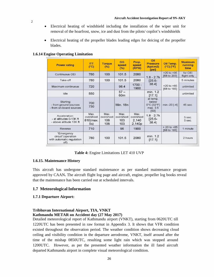
blades. 1.6.14 Engine Operating Limitation
Table 4: Engine Limitations LET 410 UVP 1.6.15. Maintenance History
This aircraft has undergone standard maintenance as per standard maintenance program approved by CAAN. The aircraft flight log page and aircraft, engine, propeller log books reveal that the maintenance has been carried out at scheduled intervals.
1.7 Meteorological Information 1.7.1 Departure Airport:
Tribhuvan International Airport, TIA, VNKT Kathmandu METAR on Accident day (27 May 2017) Detailed meteorological report of Kathmandu airport (VNKT), starting from 0620UTC till 1220UTC has been presented in raw format in Appendix 3. It shows that VFR condition existed throughout the observation period. The weather condition shows decreasing cloud ceiling and visibility condition in the departure aerodrome, VNKT, itself around after the time of the mishap 0850UTC, resulting some light rain which was stopped around 1200UTC. However, as per the presented weather information the ill fated aircraft departed Kathmandu airport in complete visual meteorological condition.
Aircraft Accident Investigation Report of 9N-AKY
27
1.7.2 Weather analysis provided by Department of Hydrology and Meteorology
1.7.2.1 Overview of the Synoptic Situation
On the 27th of May 2017 at 0600 UTC, a Northeast-Southwest low-pressure trough existed over central India with relatively higher pressure existing over eastern Nepal. The trough had Northwestwards movement and was moving closer to Nepal. By 0900 UTC, on the 27th of May, the effect of the low-pressure trough was seen over Nepal with the eastern region of Nepal showing a pressure drop of about 2 mb.
1.7.2.2 Weather Condition over eastern Nepal
Surface weather charts show that over eastern Nepal easterly wind prevailed on the morning and afternoon of the 27th of May 2017. However, central and western Nepal had westerly winds at the surface level.
Satellite Imagery shows dense low clouds over the Eastern region as seen in visible image (Appendix). Infrared imagery shows the presence of medium and high clouds as well over the Eastern region of the country with possibility of isolated CB clouds embedded within the cloud cover. (See Appendix)
1.7.3 Weather Analysis provided by Weather News International Japan
A weather camera was installed at Lukla Tower by WNI Japan through which on line weather can be accessed from Kathmandu and Japan and any other station provided the password is available. WNI analysis stated the existence of a strong warm and moist air stream over Nepal having a characteristic of active convective development. The moist air mass was moving all the way from Bay of Bengal to over Nepal and Southern Tibet. Precipitation were forecasted mainly towards Himalayan areas of Nepal. A nationwide moisture(saturated) air were forecasted at the altitude of 700hPa (about 10,000ft).A weather condition characterized by clouds, rainfall or snowfall as a result of upper trough in the mountainous areas of Nepal was forecasted at 15-18NST.
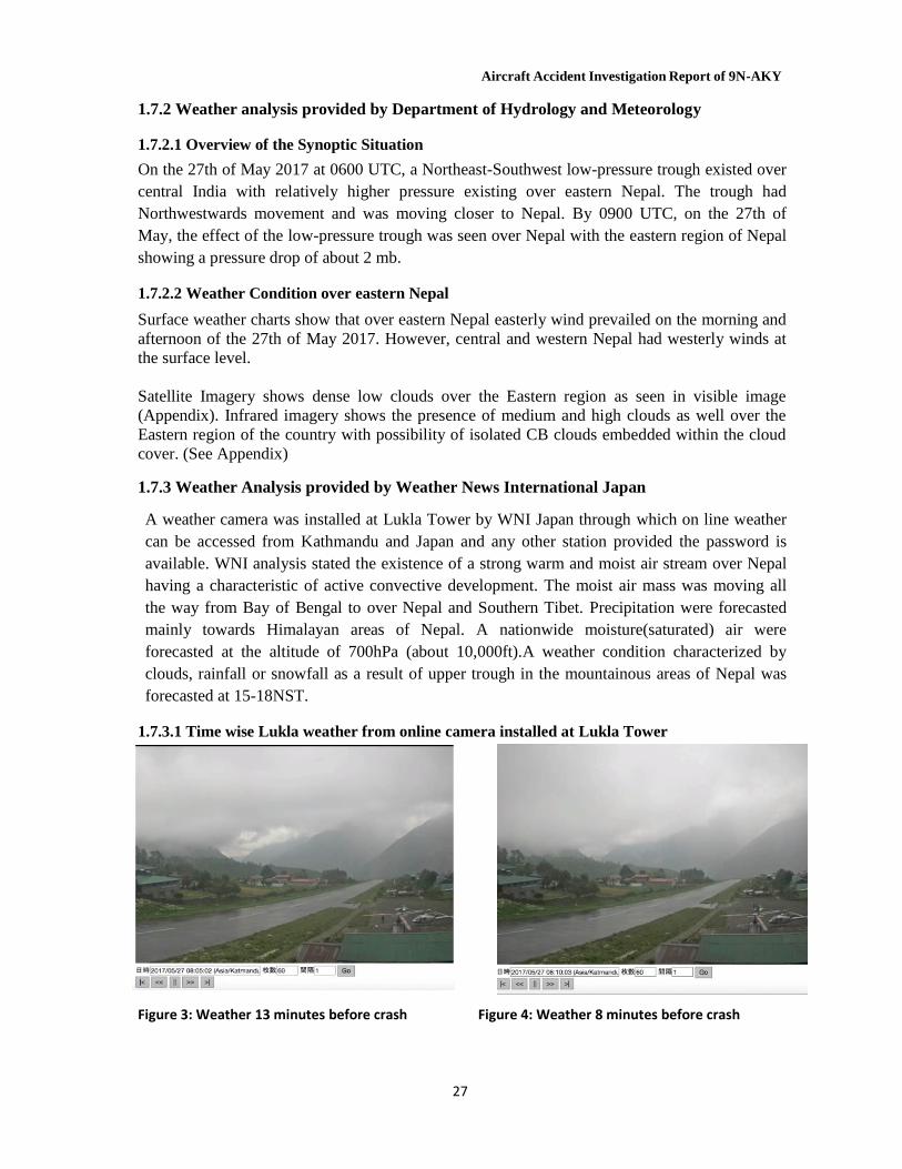
1.7.3.1 Time wise Lukla weather from online camera installed at Lukla Tower
Figure 3: Weather 13 minutes before crash Figure 4: Weather 8 minutes before crash
Aircraft Accident Investigation Report of 9N-AKY
28
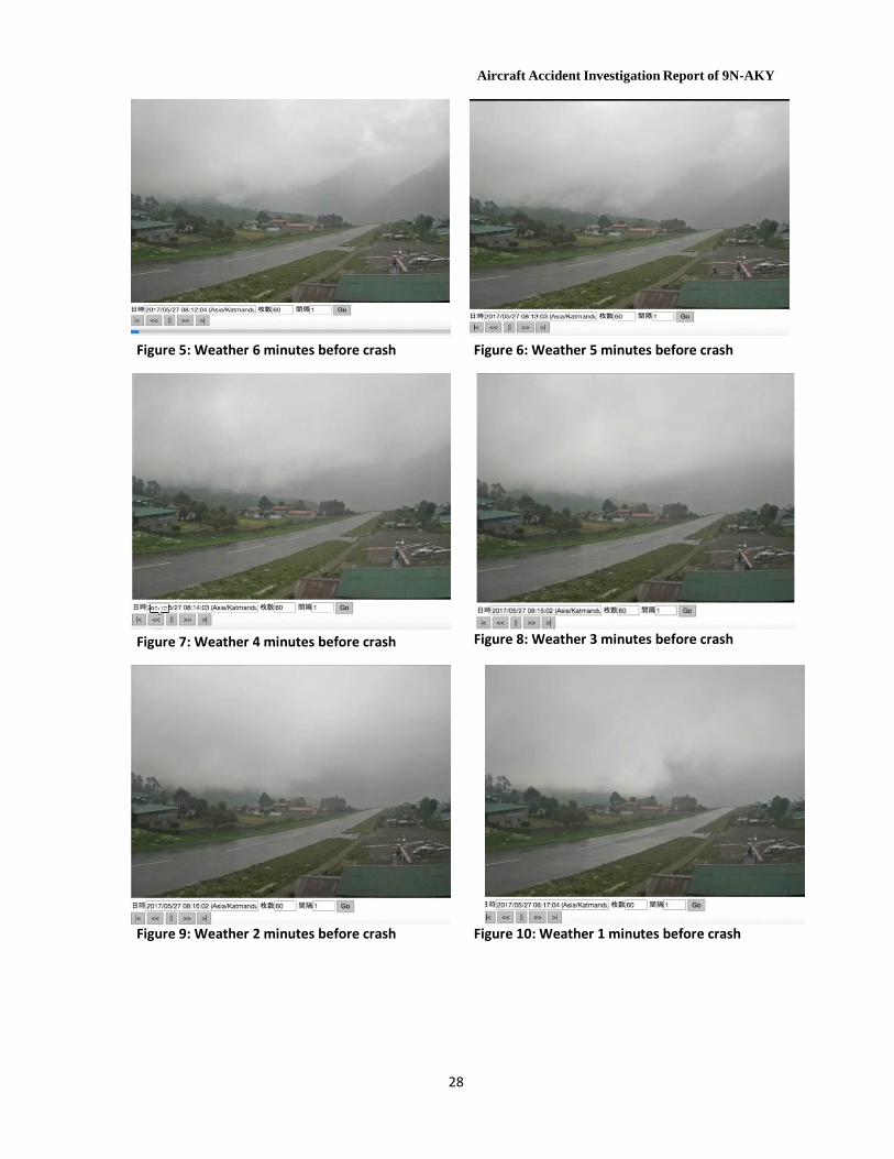
Figure 5: Weather 6 minutes before crash Figure 6: Weather 5 minutes before crash
Figure 7: Weather 4 minutes before crash Figure 8: Weather 3 minutes before crash
Figure 9: Weather 2 minutes before crash Figure 10: Weather 1 minutes before crash
Aircraft Accident Investigation Report of 9N-AKY
29
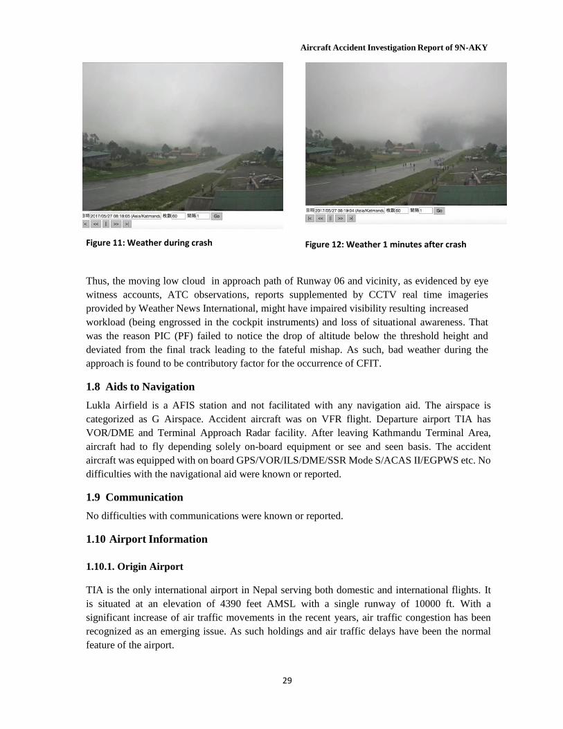
Figure 11: Weather during crash Figure 12: Weather 1 minutes after crash
Thus, the moving low cloud in approach path of Runway 06 and vicinity, as evidenced by eye witness accounts, ATC observations, reports supplemented by CCTV real time imageries provided by Weather News International, might have impaired visibility resulting increased workload (being engrossed in the cockpit instruments) and loss of situational awareness. That was the reason PIC (PF) failed to notice the drop of altitude below the threshold height and deviated from the final track leading to the fateful mishap. As such, bad weather during the approach is found to be contributory factor for the occurrence of CFIT.
1.8 Aids to Navigation
Lukla Airfield is a AFIS station and not facilitated with any navigation aid. The airspace is categorized as G Airspace. Accident aircraft was on VFR flight. Departure airport TIA has VOR/DME and Terminal Approach Radar facility. After leaving Kathmandu Terminal Area, aircraft had to fly depending solely on-board equipment or see and seen basis. The accident aircraft was equipped with on board GPS/VOR/ILS/DME/SSR Mode S/ACAS II/EGPWS etc. No difficulties with the navigational aid were known or reported.
1.9 Communication
No difficulties with communications were known or reported.
1.10 Airport Information
1.10.1. Origin Airport
TIA is the only international airport in Nepal serving both domestic and international flights. It is situated at an elevation of 4390 feet AMSL with a single runway of 10000 ft. With a significant increase of air traffic movements in the recent years, air traffic congestion has been recognized as an emerging issue. As such holdings and air traffic delays have been the normal feature of the airport.
Aircraft Accident Investigation Report of 9N-AKY
30
Aerodrome Location Indicator : VNKT Name : Tribhuvan International Airport, Kathmandu ARP Coordinates : 27°41'49.73'' N 085°21'28.53'' E Elevation : 1339.54 m (4394.76 ft) Runway Designation : 02/20 Runway Dimension : 3050*46 m* m Runway Surface : Bitumen Approach Lights & VASIS /PAPI : 02 Runway -High intensity consisting of extended center
line 870mt (29X30mt) 20 Runway- NIL, VASIS /PAPI- PAPI 3.000
Runway Lights : Centre - NIL Edge - High intensity, bi-directional raised white amber edge lights End - Red
Take off/ Landing : Both Runway Radio Navigation Aid : VOR, DME Types of Traffic Permitted : VFR, IFR ATS service : ATC service Meteorological Information Provided: METAR Refueling Facility : Available RFF : Category IX
1.10.2. Destination Airport
Lukla Airport Information: Lukla Airport is 77 NM east of Tribhuvan International Airport. The airfield is within a narrow valley surrounded by the precipitous terrain. It is a Short Takeoff and Landing (STOL) airfield having a527-meter-long and 20-meter-wide bitumen runway. Orientation of the runway is 24 and 06 with one way takeoff from RWY 24 and landing from RWY 06 only. Runway is up slope from 06 with a gradient 11.75%. There is a high terrain to the end of RWY 06 (towards North). Hence; once final approach is executed, go around is not possible. There are 4 parking lots for STOL aircraft and a separate helipad for 4 small helicopters.
Meteorological condition of Lukla is very unpredictable. No Meteorological Watch Office is established at Lukla Airport. Under the tri-party MOU among Department of Hydrology and Meteorology, CAAN and Weather News Japan, a meteorological observation camera is installed outside the Lukla Tower facing towards approach path and South of the valley. Weather information from the camera can be assessed on line from Kathmandu, Japan and from anywhere, provided password is available. But its information is not available at Lukla Tower. Lukla Tower console has the display facility of QNH altimeter and air temperature, but as the equipment is not calibrated those facilities are not available and instead Kathmandu QNH is provided for altimeter setting as per provision provided in AIP regarding altimeter setting in uncontrolled airspace in Nepal. Duty ATS Officer provide visual weather observation based on established procedure. Wind sock is provided at the end of the Runway 06 and at the middle of the runway close to helipad. Surface wind information from the windsock at the end of the runway is not available at the Console anemometer. In that situation duty officer has to provide surface wind information based on his judgment looking at the wind sock.

Aircraft Accident Investigation Report of 9N-AKY
31
a) Ramechhap: Aerodrome Location Indicator
: VNRC Name : Ramechhap ARP Coordinates
Elevation Runway Designation
: 272338 N *0860341E : 1620 ft 494 m : 03/21
Runway Dimension Runway Surface
: 1738 × 65 ft 530 × 20 m* m : Bitumen
Approach & Runway Lighting : NA Radio Navigation Aid : NA Types of Traffic Permitted : VFR ATS service : FIS
Refueling Facility
: NA RFF : NA
b)
Phaplu:
Aerodrome Location Indicator : VNPL Name : Phaplu ARP Coordinates
Elevation Runway Designation
: 273053 N *0863510 E : 8097 ft 2468 m : 02/20
Runway Dimension Runway Surface
: 2230 × 65 ft 680 × 20 m* m : Bitumen
Approach & Runway Lighting : NA Take off/ Landing : landing 20. takeoff 20, but sometimes 02 used as well for takeoff. Radio Navigation Aid : NA
Lukla is a AFIS Aerodrome. Aerodrome Flight Information Service (AFIS) is the term used to describe the provision of information useful for the safe and efficient conduct of aerodrome traffic. AFIS is not an ATC Unit, therefore pilots are responsible to maintain proper separation. AFIS airspace is Class G airspace where flight information and alerting service is provided to aerodrome traffic. Lukla being the AFIS Aerodrome IFR flights are not permitted. Civil Aviation Authority has established a Generic SOP at Lukla Airport for Fixed Wing Aircraft. Generic SOP provide necessary guidelines to duty ATS officer in determining required Visibility and Ceiling for VFR operation. SOP also authorizes a duty ATS Officer to declare airfield closed under the conditions: when visibility is less than 5000m, or ceiling height is less than 1500m or if the tail wind exceeds 10 kts or if there is light rain.
Tenjing Hilary Airport (Lukla) is the second busiest airport of the country after TIA in terms of flight movements. Though VAGS and A-PAPI was installed as landing aid, they were not in use because of calibration issues.
1.10.3 Alternate Airport
Meteorological Information Provided: NA
Aircraft Accident Investigation Report of 9N-AKY
32
Types of Traffic Permitted : VFR ATS service : FIS Meteorological Information Provided: NA Refueling Facility : NA RFF : NA
1.11 Flight Recorder
The aircraft was fitted with a 25-hour FDR and 2 hours CVR. As there was no post-crash fire both CVR and FDR were collected intact. FDR data was retrieved and analyzed successfully at the Manufacturer's facility of Let 410 i.e. Aircraft Industry, a.c., at Kunovice, Czech Republic.
1.11.1 FDR Details
MADRAS (Modular Airborne Data Recording Acquisition System) FDR FA 2200-2600-00. Model OK 129, P/N: 2202-200-00 S/N: 001044744 TSO-121, Manufacturer: DukaneSeacom, Inc., Sarasota FL, USA.
FDR recorded the basic parameters like – airspeed, altitude, magnetic heading, position of flaps, elevators, landing gears, rudders and engine torques etc. Comparative charts were prepared of the basic FDR data of last 3 minutes duration of the last three flights. Besides, a separate comparative table of last 30 seconds flying period of last 3 flights were also prepared so as to identify the changes in basic parameters.
1.11.2. CVR Details
The crashed aircraft was equipped with TSO C123a Cockpit Voice Recorder manufactured by Farechild Model FA2100. The CVR had last 2 hours of audio recording on separate channels for each pilot and the Cockpit Area Microphone (CAM).
1.12 Wreckage impact information:
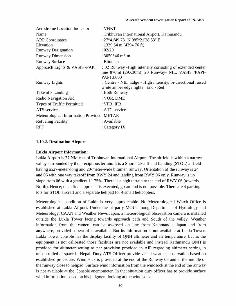
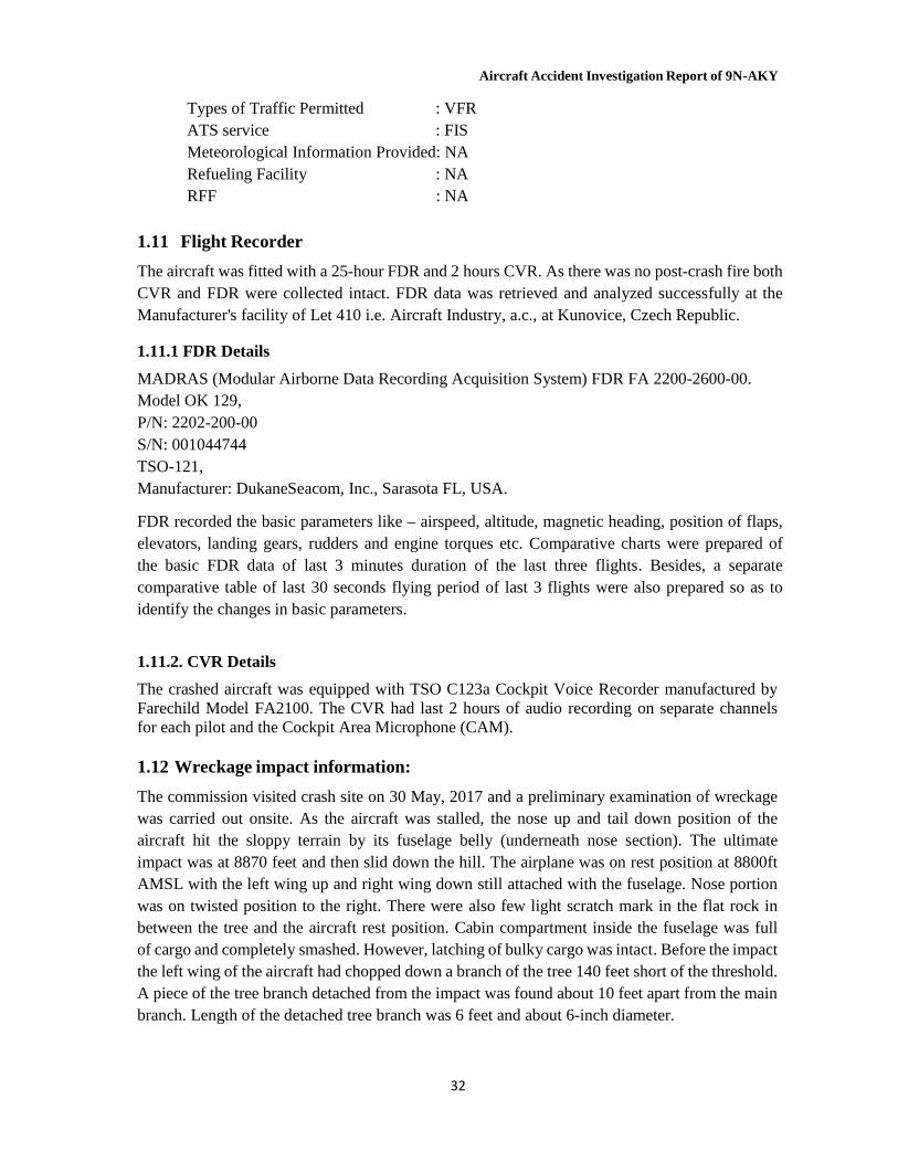
The commission visited crash site on 30 May, 2017 and a preliminary examination of wreckage was carried out onsite. As the aircraft was stalled, the nose up and tail down position of the aircraft hit the sloppy terrain by its fuselage belly (underneath nose section). The ultimate impact was at 8870 feet and then slid down the hill. The airplane was on rest position at 8800ft AMSL with the left wing up and right wing down still attached with the fuselage. Nose portion was on twisted position to the right. There were also few light scratch mark in the flat rock in between the tree and the aircraft rest position. Cabin compartment inside the fuselage was full of cargo and completely smashed. However, latching of bulky cargo was intact. Before the impact the left wing of the aircraft had chopped down a branch of the tree 140 feet short of the threshold. A piece of the tree branch detached from the impact was found about 10 feet apart from the main branch. Length of the detached tree branch was 6 feet and about 6-inch diameter.
Aircraft Accident Investigation Report of 9N-AKY
33
Figure 13: Picture of detached tree
Figure 14: Photo of wreckage
Aircraft Accident Investigation Report of 9N-AKY
21
1.13 Medical and Pathological information
Both pilots were in good health and did not have any disease or illness. They did not have any significant physical or psychological problems in the history. There was no obvious incident or event that could degrade their performance like stress, fatigue, lack of sleep or food, mishap, etc. Their regular medical examinations were normal and accordingly certified.
BLUNT FORCE INJURIES TO HEAD, CHEST AND ABDOMEN were likely cause of death of the both crew.
Both crew's Viscera from stomach, kidney and liver were tested for insecticides (organo- phosphorous, organo-chlorine, carbamate, pyrethroid), ethyl alcohol, methyl alcohol and phosphine gas. The sample was negative for all chemicals analyzed.
Blood samples were tested for ethyl alcohol by micro diffusion method, which was found negative for both crews.
Cabin crew sustained serious injuries during the crash. She was evacuated to Kathmandu the next day. She was under medical care and now almost normal.
1.14 Fire
After the crash aircraft engine was reported to be running for about a minute. But there was no post-crash fire.
1.15 Survival Aspects
Air Hostess who was on the rear seat was fully conscious and rescued within 20 minutes. PIC was fatally injured due to the impact. First Officer who was unconscious had to be rescued by cutting cockpit door which took almost 45 minutes. First Officer and Air Hostess were rushed to the local hospital at Lukla. Effort to air lift both of them to Kathmandu was not successful due to bad weather. The First Officer passed away in Lukla hospital. Air Hostess was air lifted to Grandy Hospital, Kathmandu next morning. She survived and now is almost normal.
1.16 Test and Research
CVR and FDR data was retrieved and analyzed in the Manufacturer's facility at Kunovice, Czech Republic. No further technical test or research was considered to be necessary.
1.16.1 Fuel Status
Fuel state of the aircraft up for the period leading up to time of accident was examined. Aircraft uplifted 440 ltr. of fuel from Kathmandu giving fuel endurance of 0200 hours. The normal fuel consumption rate of the aircraft was 300 kgs per hours. Estimated endurance remaining at time of accident was 0130 hrs. sufficient for the aircraft to fly to destination Lukla and back to Kathmandu or alternate airport Phaplu.
Aircraft Accident Investigation Report of 9N-AKY
22
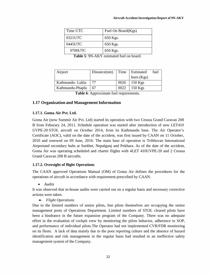
Time UTC Fuel On Board(Kgs)
0321UTC 650 Kgs.
0445UTC 650 Kgs.
0700UTC 650 Kgs.
Table 5: 9N-AKY estimated fuel on board.
Airport Distance(nm) Time Estimated fuel burn (Kgs)
Kathmandu- Lukla 77 0026 150 Kgs Kathmandu-Phaplu 67 0022 150 Kgs
Table 6: Approximate fuel requirements. 1.17 Organization and Management Information
1.17.1. Goma Air Pvt. Ltd.
Goma Air (now Summit Air Pvt. Ltd) started its operation with two Cessna Grand Caravan 208 B from Feburary 24, 2011. Schedule operation was started after introduction of new LET410 UVPE-20 STOL aircraft on October 2014, from its Kathmandu base. The Air Operator’s Certificate (AOC), valid on the date of the accident, was first issued by CAAN on 11 October, 2010 and renewed on 09 June, 2016. The main base of operation is Tribhuvan International Airportand secondary hubs at Surkhet, Nepalgunj and Pokhara. As of the date of the accident, Goma Air was operating scheduled and charter flights with 4LET 410UVPE-20 and 2 Cessna Grand Caravan 208 B aircrafts.
1.17.2. Oversight of flight Operations
The CAAN approved Operations Manual (OM) of Goma Air defines the procedures for the operations of aircraft in accordance with requirement prescribed by CAAN.
Audits It was observed that in-house audits were carried out on a regular basis and necessary corrective actions were taken.
Flight Operations Due to the limited numbers of senior pilots, line pilots themselves are occupying the senior management posts of Operations Department. Limited numbers of STOL cleared pilots have been a hindrance in the future expansion program of the Company. There was no adequate effort in the evaluation of cockpit crew by monitoring the pilots behavior, adherence to SOP, and performance of individual pilots.The Operator had not implemented CVR/FDR monitoring on its fleets. A lack of data mainly due to the poor reporting culture and the absence of hazard identification and risk management in the regular basis had resulted in an ineffective safety management system of the Company.
Aircraft Accident Investigation Report of 9N-AKY
23
Goma Air has not established Flight Following System to monitor the progress and whereabouts of their flight
1.17.3 Incident Records
The ill fated aircraft 9N-AKY had a nose wheel collapse incident at Pokhara Airport (VNPK) on 05 Jun 2015. (No Fatalities.)
1.17.4 Review of Goma Air's Flight Training Manual
Goma Air has developed and designed Training Manual as per the Flight Operations Requirements (FOR) of Civil Aviation Authority of Nepal incorporating it in the Operation Manual Part D. The Manual is developed to ensure each person involved with Goma Air operations are provided with the required training, as spelled out in FOR to perform their assigned duties. The training include required initial ground and flight training including training relating to abnormal and emergency procedures.
The Operation Department is responsible for training matters and also to ensure all flight crew, dispatcher and other operational personnel are current in all mandatory training, checks and tests as specified in Part D.
While reviewing Company's Stall and Stall Recovery training to the flight crew, it was found to be incorporated in the LET 410 UVP E-20 Type Simulator Check.
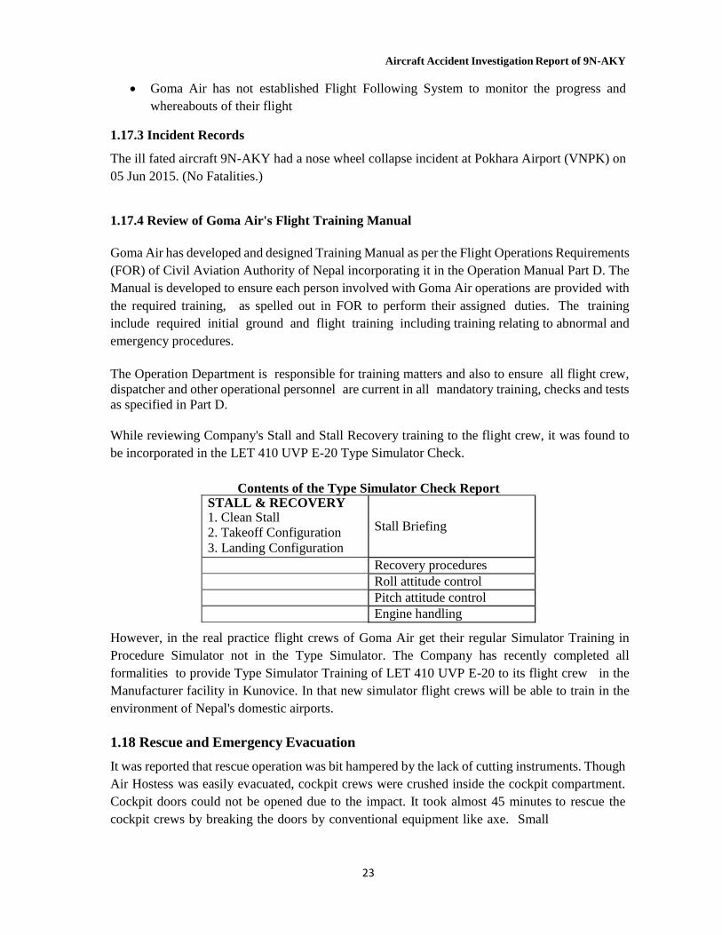
Contents of the Type Simulator Check Report
STALL & RECOVERY 1. Clean Stall 2. Takeoff Configuration 3. Landing Configuration
Stall Briefing
Recovery procedures Roll attitude control Pitch attitude control Engine handling
However, in the real practice flight crews of Goma Air get their regular Simulator Training in Procedure Simulator not in the Type Simulator. The Company has recently completed all formalities to provide Type Simulator Training of LET 410 UVP E-20 to its flight crew in the Manufacturer facility in Kunovice. In that new simulator flight crews will be able to train in the environment of Nepal's domestic airports.
1.18 Rescue and Emergency Evacuation
It was reported that rescue operation was bit hampered by the lack of cutting instruments. Though Air Hostess was easily evacuated, cockpit crews were crushed inside the cockpit compartment. Cockpit doors could not be opened due to the impact. It took almost 45 minutes to rescue the cockpit crews by breaking the doors by conventional equipment like axe. Small

Aircraft Accident Investigation Report of 9N-AKY
24
Fire Tender available at the airport lacked basic equipment like electric Hack saw blade, axe and adequate manpower.
Aircraft Accident Investigation Report of 9N-AKY
25
2. Analysis
2.1. Introduction
The analysis of the events which led to the accident began with the careful scrutiny of the factors such as technical defects, unlawful interference, explosions, pilot incapacitation, and lack of training/qualification/experience which could have contributed to the accident.
The primary cause and contributory factors to this accident derived from the analysis of the facts and evidences gathered in this context are narrated hereunder.
2.2. Methodology
In order to determine the situation and probable cause of the accident of 9N-AKY, the following methodology was employed:
2.2.1 Analysis of CVR and FDR The Commission had successfully retrieved the CVR and FDR data and analyzed them from different angles. The CVR record was found very helpful in analyzing the cockpit scenario before and during the last phase of accident. CVR data was complemented with FDR data to determine the cause of the accident.
2.2.2 Study and Analysis of Log Books, Records, Documents and Manuals
Airframe, engine and aircraft technical log books were reviewed and examined to assess any discrepancy and malfunctioning of the aircraft system. Operations Manual, Flight Safety Manual, Aircraft Flight Manual, Standard Operating Procedure, Pilot records were checked and reviewed. CAAN approved FOR, NCAR, AOCR, AIP were also reviewed. Similarly, the relevant documents were reviewed and discussed with concerned personnel.
2.3.1 Analysis of CVR information:
Following are summary of the crucial information extracted from inter and intra cockpit communication recorded in CVR which provide clear picture of actual flying environment of the fateful flight:
- As the weather towards direct track was not favorable, aircraft was flying south of track. - Though Lukla weather was good in the beginning, later that was rapidly deteriorated. - Lukla Tower was continuously updating the pilots about the deteriorating weather. - Aircraft was flying low in an attempt to maintain VMC. - Once the flight entered Lukla valley, weather was further deteriorated, crew had to struggle
in maintaining visual flight rules. - At times, there was apparent expression of frustration from PIC as a result of unfavorable
weather conditions. - PIC was repeatedly asking with Lukla Tower whether there was rain in the airfield. - 64 seconds before impact First Officer sighted the runway. Perhaps excited by sighting the
runway he repeated that 3 times. Instantly PIC also acknowledged, he also sighted the runway. - Aircraft landing gear was lowered down once the runway was sighted.

Aircraft Accident Investigation Report of 9N-AKY
26
- 35 seconds before the impact full flap was selected. - 25 seconds before the impact there was repeated call out from the First Officer warning that
they were low. Ultimately, the F/O said they reached 8500ft in panic whereas threshold height is at 8900 ft (Kathmandu QNH).
- PIC seemed to have lost runway in sight that might be because of illusion or loss of situational awareness because he was too much occupied with cockpit instrument. Aircraft deviated to the right and also went too low.
- There was continuous stall warning sound for 14 second. - Both pilots reacted quickly pulling the control panel to gain height whereby PIC said ‘do not
pull too much’. - In an attempt to climb abruptly from the landing configuration (with landing gears down and
on full flaps setting) together with the excessive increase in the angle of attack lead the aircraft to stall and ultimately impacted the ground.
2.3.2. Analysis of FDR
The aircraft was equipped with MADRAS (Modular Airborne Data Recording Acquisition System) FDR FA 2200-2600-00. It had no controls or switches and its operation was completely automatic upon power-up. It had the capability of recording 25 hours data on several parameters which can be retrieved and analyzed as and when required.
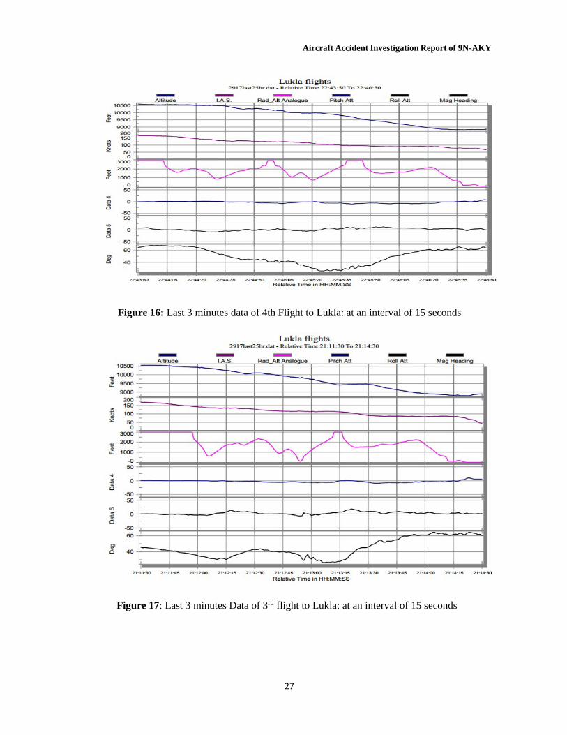
All parameters were found normal and within the limit. To get into the actual cause of accident, the Commission minutely analyzed the FDR data of crashed flight and two previous flights before crash of the same aircraft. Following Fig. ...Shows the comparative data of six different parameters.
Figure 15: Last 3 minutes Data of 5th flight (crashed flight) : at an interval of 15 seconds
Aircraft Accident Investigation Report of 9N-AKY
27
Figure 16: Last 3 minutes data of 4th Flight to Lukla: at an interval of 15 seconds
Figure 17: Last 3 minutes Data of 3rd flight to Lukla: at an interval of 15 seconds
Aircraft Accident Investigation Report of 9N-AKY
28
30
25
20 P 15 i t 10
c h 5
0
-5
-10
Crash
Previous Flight 2
Previous Flight 3
Figure 18: Comparison of Pitch attitude among last three consecutive flights of 9N- AKY on 27th May 2017.
9000 8900
A l
8800
t 8700
i t 8600 u d 8500 e
8400
Crash
Previous Flight 2
Previous Flight 3
8300
Figure 19: Comparison of Altitude profile among last three consecutive flights of 9N-AKY on
27th May 2017.
Aircraft Accident Investigation Report of 9N-AKY
29
120
Crash
100
80
I A 60
S
40
Previous Flight 2 Previous Flight 3
20
0
Figure 20: Comparison of Indicated air speed (IAS) among last three consecutive flights of 9N-AKY on 27th May 2017.
Referring to above charts, the aircraft was flying low during final moments of its flight. On the final minute IAS was significantly low which dropped below 50Kt during final few seconds then further down below 20 kt. Pitch attitude was at maximum during final seconds. Magnetic heading was abruptly changed in the last moment. Following comparative chart will further elaborate the final parameters of crashed flight and other two flights previous to the occurrence.
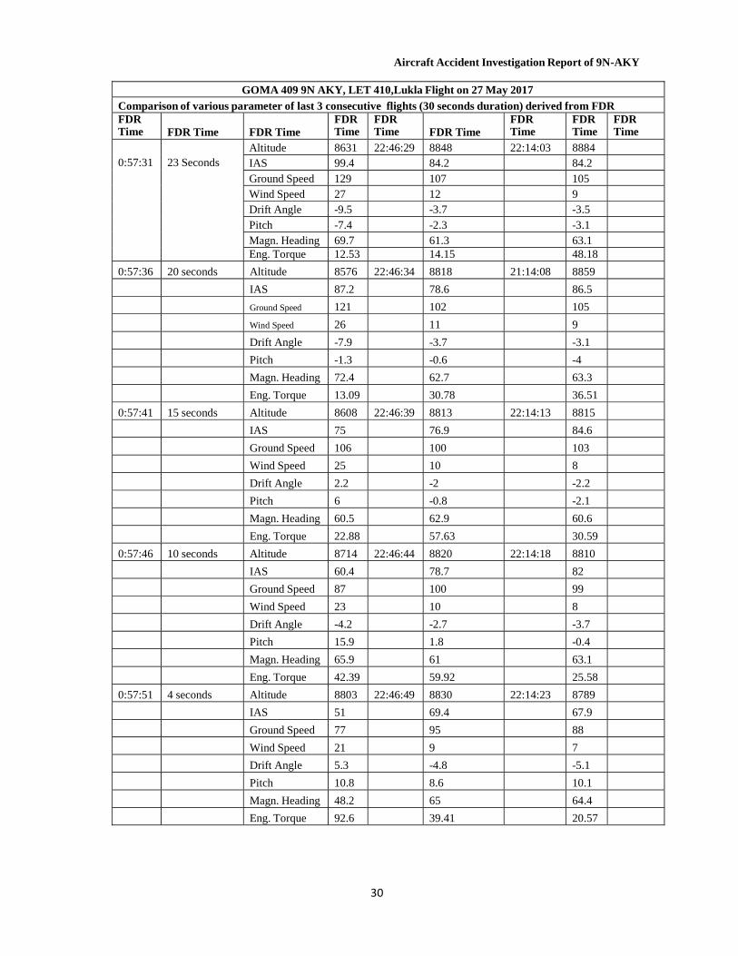
Comparison of various parameters of last 3 consecutive flights to Lukla of 9N AKY, LET 410 (last 30 seconds duration) derived from FDR is illustrated below:
Comparison of various parameters of last 3 consecutive flights derived from FDR
GOMA 409 9N AKY, LET 410,Lukla Flight on 27 May 2017
Comparison of various parameter of last 3 consecutive flights (30 seconds duration) derived from FDR FDR Time
Time before Crash
Crash Flight
FDR Time
Previous Flt
FDR Time
3rd
Remark
0:54:24
30 second
Altitude 8701 22:46:22 8932 21:13:56 8947
IAS 105.2 90.9 84.7
Ground Speed 141 114 106
Wind Speed 27 12 10
Drift Angle -7.1 3.3 -1.9
Pitch -5.6 -7.1 -4.7
Magn. Heading 62 60 60.4
Engine Torque 12.42 14.19 23.71
Aircraft Accident Investigation Report of 9N-AKY
GOMA 409 9N AKY, LET 410,Lukla Flight on 27 May 2017
Comparison of various parameter of last 3 consecutive flights (30 seconds duration) derived from FDR FDR Time
FDR Time
FDR Time
FDR Time
FDR Time
FDR Time
FDR Time
FDR Time
FDR Time
0:57:31
23 Seconds
Altitude 8631 22:46:29 8848 22:14:03 8884
IAS 99.4 84.2 84.2
Ground Speed 129 107 105
Wind Speed 27 12 9
Drift Angle -9.5 -3.7 -3.5
Pitch -7.4 -2.3 -3.1
Magn. Heading 69.7 61.3 63.1 Eng. Torque 12.53 14.15 48.18
0:57:36 20 seconds Altitude 8576 22:46:34 8818 21:14:08 8859
IAS 87.2 78.6 86.5
Ground Speed 121 102 105
Wind Speed 26 11 9
Drift Angle -7.9 -3.7 -3.1
Pitch -1.3 -0.6 -4
Magn. Heading 72.4 62.7 63.3
Eng. Torque 13.09 30.78 36.51
0:57:41 15 seconds Altitude 8608 22:46:39 8813 22:14:13 8815
IAS 75 76.9 84.6
Ground Speed 106 100 103
Wind Speed 25 10 8
Drift Angle 2.2 -2 -2.2
Pitch 6 -0.8 -2.1
Magn. Heading 60.5 62.9 60.6
Eng. Torque 22.88 57.63 30.59
0:57:46 10 seconds Altitude 8714 22:46:44 8820 22:14:18 8810
IAS 60.4 78.7 82
Ground Speed 87 100 99
Wind Speed 23 10 8
Drift Angle -4.2 -2.7 -3.7
Pitch 15.9 1.8 -0.4
Magn. Heading 65.9 61 63.1
Eng. Torque 42.39 59.92 25.58
0:57:51 4 seconds Altitude 8803 22:46:49 8830 22:14:23 8789
IAS 51 69.4 67.9
Ground Speed 77 95 88
Wind Speed 21 9 7
Drift Angle 5.3 -4.8 -5.1
Pitch 10.8 8.6 10.1
Magn. Heading 48.2 65 64.4
Eng. Torque 92.6 39.41 20.57
30
Aircraft Accident Investigation Report of 9N-AKY
31
2.3.3 Operational analysis of the final 4 minutes and 27 seconds The flight crews were aware of deteriorating weather at Lukla. They were asked to expedite arrival by Lukla Tower. Ceiling and visibility were rapidly deteriorating below the prescribed minima, and this was contrary to the approved SOP of Lukla Airport and also of the GOMA AIR SOP. Contrary to the basic requirement prescribed by the SOP, the airport was not declared closed. They had also received PIREPs reports about unstable approach on short final Lukla runway 06 from a helicopter, 9N-AGU, which had departed Lukla for Kathmandu. When they crossed BhatkekoDaada, which is 10 GPS NM south of Lukla airport, the crew mistook a layer of cloud for a terrain wall towards Lukla valley and were following DudhKoshi river with assistance from their GPS equipment.
They entered Lukla valley at 9,200 ft. which normally should be 10,500 ft. That counted as a violation of SOPs (both GOMA AIR as well as Lukla Airport SOP). The flight crew were not able to see the final glide path for landing to runway 06 and they were informed about the rapidly increasing thick fog towards the left as well as the right base of runway 06. The pilot monitoring had spotted the runway at exactly 64 second before impact and so did the Captain 2 seconds later.
The flight crew had configured the airplane with flaps fully extended and landing gear down for landing 35 seconds ahead of the impact. The Pilot monitoring did not lose sight of the runway till impact but the Captain (PF) could not maintain the runway in sight during the last 25 seconds due to several reasons. The reasons might be lack of situational awareness, high workload, low visibility, a fixed mind-set to land due to high severity of risk produced by surrounding terrain, aircraft being lower than the runway threshold and still not being able to sight the runway and Captain's intention to climb to reach threshold height of 8900 ft. from 8500ft. (using KTM, QNH). During the last 10 seconds, both pilots took cross control of the aircraft. In their attempt to climb the aircraft in landing configuration to 8900 ft. from 8500ft. the aircraft lost a substantial amount of speed from 75 knots to 19 knots within the time frame of 13 seconds with continuous stall warning. The stall recovery procedure is to apply maximum engine torque, lower the nose and reconfigure the aircraft stepwise but the Captain only partially applied engine torque to 22%, 42% and 92% in the interval of 4.33 seconds, respectively, and the pitch rose from +6 degrees to +27.6 degrees. The airplane fell “behind the power curve” and then proceeded to stall and impact on the sloppy terrain 130 ft. short of the runway threshold. It came to rest 100 ft. below the runway threshold 06.
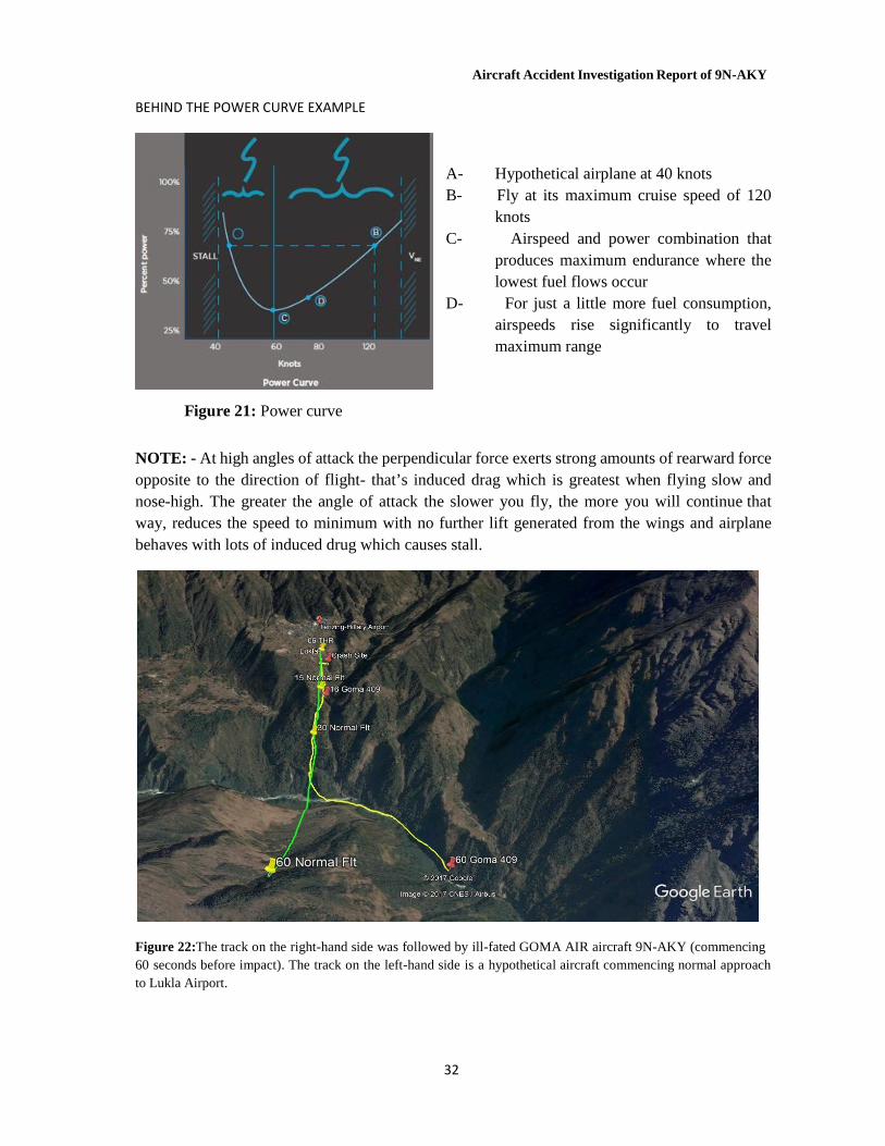
Aircraft Accident Investigation Report of 9N-AKY
32
BEHIND THE POWER CURVE EXAMPLE
Figure 21: Power curve
A- Hypothetical airplane at 40 knots B- Fly at its maximum cruise speed of 120
knots C- Airspeed and power combination that
produces maximum endurance where the lowest fuel flows occur
D- For just a little more fuel consumption, airspeeds rise significantly to travel maximum range
NOTE: - At high angles of attack the perpendicular force exerts strong amounts of rearward force opposite to the direction of flight- that’s induced drag which is greatest when flying slow and nose-high. The greater the angle of attack the slower you fly, the more you will continue that way, reduces the speed to minimum with no further lift generated from the wings and airplane behaves with lots of induced drug which causes stall.
Figure 22:The track on the right-hand side was followed by ill-fated GOMA AIR aircraft 9N-AKY (commencing 60 seconds before impact). The track on the left-hand side is a hypothetical aircraft commencing normal approach to Lukla Airport.
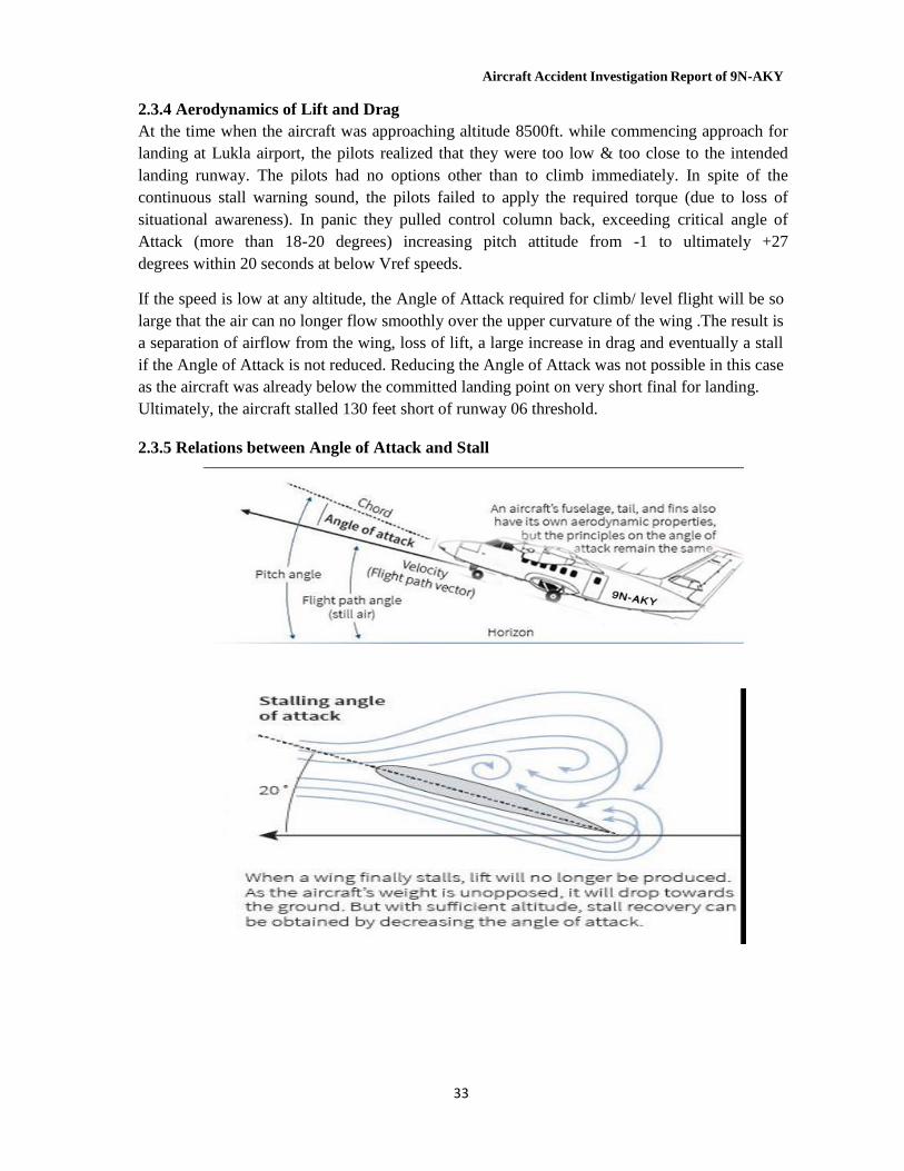
Aircraft Accident Investigation Report of 9N-AKY
33
2.3.4 Aerodynamics of Lift and Drag At the time when the aircraft was approaching altitude 8500ft. while commencing approach for landing at Lukla airport, the pilots realized that they were too low & too close to the intended landing runway. The pilots had no options other than to climb immediately. In spite of the continuous stall warning sound, the pilots failed to apply the required torque (due to loss of situational awareness). In panic they pulled control column back, exceeding critical angle of Attack (more than 18-20 degrees) increasing pitch attitude from -1 to ultimately +27 degrees within 20 seconds at below Vref speeds.
If the speed is low at any altitude, the Angle of Attack required for climb/ level flight will be so large that the air can no longer flow smoothly over the upper curvature of the wing .The result is a separation of airflow from the wing, loss of lift, a large increase in drag and eventually a stall if the Angle of Attack is not reduced. Reducing the Angle of Attack was not possible in this case as the aircraft was already below the committed landing point on very short final for landing. Ultimately, the aircraft stalled 130 feet short of runway 06 threshold.
2.3.5 Relations between Angle of Attack and Stall
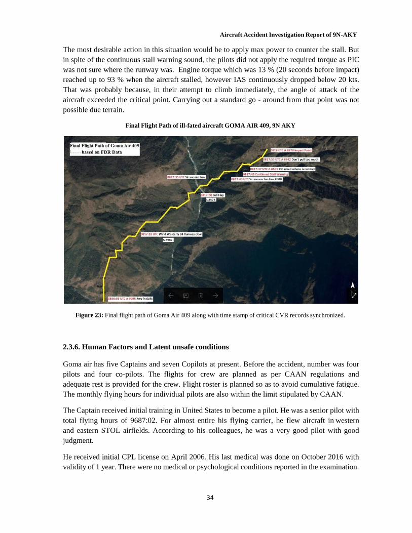
Aircraft Accident Investigation Report of 9N-AKY
34
The most desirable action in this situation would be to apply max power to counter the stall. But in spite of the continuous stall warning sound, the pilots did not apply the required torque as PIC was not sure where the runway was. Engine torque which was 13 % (20 seconds before impact) reached up to 93 % when the aircraft stalled, however IAS continuously dropped below 20 kts. That was probably because, in their attempt to climb immediately, the angle of attack of the aircraft exceeded the critical point. Carrying out a standard go - around from that point was not possible due terrain.
Final Flight Path of ill-fated aircraft GOMA AIR 409, 9N AKY
Figure 23: Final flight path of Goma Air 409 along with time stamp of critical CVR records synchronized. 2.3.6. Human Factors and Latent unsafe conditions
Goma air has five Captains and seven Copilots at present. Before the accident, number was four pilots and four co-pilots. The flights for crew are planned as per CAAN regulations and adequate rest is provided for the crew. Flight roster is planned so as to avoid cumulative fatigue. The monthly flying hours for individual pilots are also within the limit stipulated by CAAN.
The Captain received initial training in United States to become a pilot. He was a senior pilot with total flying hours of 9687:02. For almost entire his flying carrier, he flew aircraft in western and eastern STOL airfields. According to his colleagues, he was a very good pilot with good judgment.
He received initial CPL license on April 2006. His last medical was done on October 2016 with validity of 1 year. There were no medical or psychological conditions reported in the examination.
Aircraft Accident Investigation Report of 9N-AKY
35
He was helpful, optimistic and calm in nature. He would not take any decision in haste and would think about each aspect in detail and then only would come to a conclusion. He was not impulsive. In flying also, he was very calm personality and would do everything as per the guidelines.
He was fun loving person and would love making people laugh and used to tell funny jokes all the time. He got along well with everyone. He had a very routine life and would do most of his work as per schedule. He was fairly satisfied with his job and wanted to carry on with this job for a long time. He wanted to get into agriculture business, have own farm house and retire after 5-6 years. He was socially involved and has donated to charities. He loved helping people and also loved to spend time with his family. The Captain was a social drinker only and he didn’t smoke. He had no addictions to any kind of drugs. The blood samples were also negative for any substance abuse.
He had a very nice and comfortable environment at home. There were no family problems and he was fairly secured financially. He was married and had two children.
He had adequate rest at home prior to this flight. His daily routine on the evening before the fateful accident was normal with no specific events. His flight duties did not suggest any cumulative fatigue and work load was managed well by the company. There were no circumstances to suspect that crew had suffered hypoxia.
The First Officer attended aviation school, in The Philippines. He received his initial CPL license in March 2015. His last medical was done in March 2016 with validity of 1 year. There were no medical or psychological conditions reported in the examination.
The Co-Pilot had worked for Goma Air for the last two years (since 23rd August 2015). He had 1311:00 hours of flying experience. He had mostly flown similar aircraft as passenger or cargo operations with Goma Air.
The Co-pilot was very sincere, hardworking and calm person. He was very methodical in the way he would approach anything in life and so was the case during his flying as well. He would analyze all factors in great detail before committing to any decision. He was competent as a co- pilot according to his colleagues.
The First Officer had a dream to be an Air Transport Pilot. He was planning to begin training for flying an Airbus. He had planned to leave his current job to pursue his dreams in the time to come.
He was a social person and would easily mix with friends and colleagues. He did not drink or smoke. He did not have any addiction to any kind of drugs. The blood samples were also negative for any substance abuse.
He had a good night rest prior to the night of the flight. His flight routine did not suggest any cumulative fatigue. This was his 5th flight for the day. He did not seem to be fatigued and there was no evidence to suggest that he suffered from hypoxia.
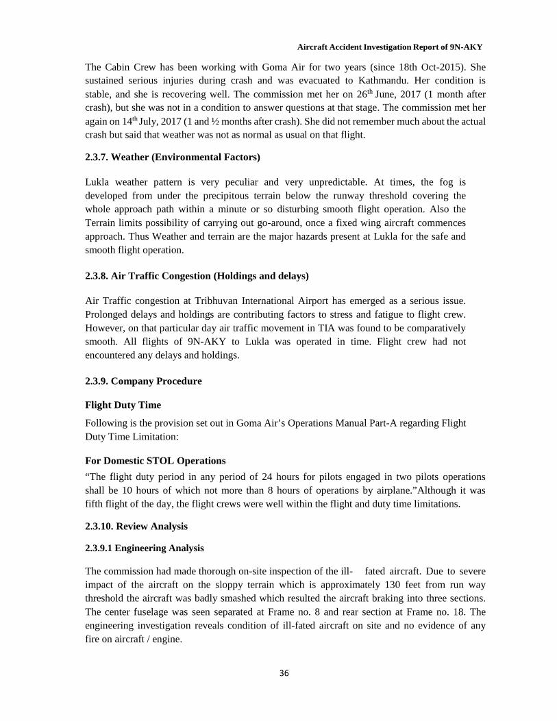
Aircraft Accident Investigation Report of 9N-AKY
36
The Cabin Crew has been working with Goma Air for two years (since 18th Oct-2015). She sustained serious injuries during crash and was evacuated to Kathmandu. Her condition is stable, and she is recovering well. The commission met her on 26th June, 2017 (1 month after crash), but she was not in a condition to answer questions at that stage. The commission met her again on 14th July, 2017 (1 and ½ months after crash). She did not remember much about the actual crash but said that weather was not as normal as usual on that flight.
2.3.7. Weather (Environmental Factors)
Lukla weather pattern is very peculiar and very unpredictable. At times, the fog is developed from under the precipitous terrain below the runway threshold covering the whole approach path within a minute or so disturbing smooth flight operation. Also the Terrain limits possibility of carrying out go-around, once a fixed wing aircraft commences approach. Thus Weather and terrain are the major hazards present at Lukla for the safe and smooth flight operation.
2.3.8. Air Traffic Congestion (Holdings and delays)
Air Traffic congestion at Tribhuvan International Airport has emerged as a serious issue. Prolonged delays and holdings are contributing factors to stress and fatigue to flight crew. However, on that particular day air traffic movement in TIA was found to be comparatively smooth. All flights of 9N-AKY to Lukla was operated in time. Flight crew had not encountered any delays and holdings.
2.3.9. Company Procedure
Flight Duty Time
Following is the provision set out in Goma Air’s Operations Manual Part-A regarding Flight Duty Time Limitation:
For Domestic STOL Operations
“The flight duty period in any period of 24 hours for pilots engaged in two pilots operations shall be 10 hours of which not more than 8 hours of operations by airplane.”Although it was fifth flight of the day, the flight crews were well within the flight and duty time limitations.
2.3.10. Review Analysis
2.3.9.1 Engineering Analysis
The commission had made thorough on-site inspection of the ill- fated aircraft. Due to severe impact of the aircraft on the sloppy terrain which is approximately 130 feet from run way threshold the aircraft was badly smashed which resulted the aircraft braking into three sections. The center fuselage was seen separated at Frame no. 8 and rear section at Frame no. 18. The engineering investigation reveals condition of ill-fated aircraft on site and no evidence of any fire on aircraft / engine.
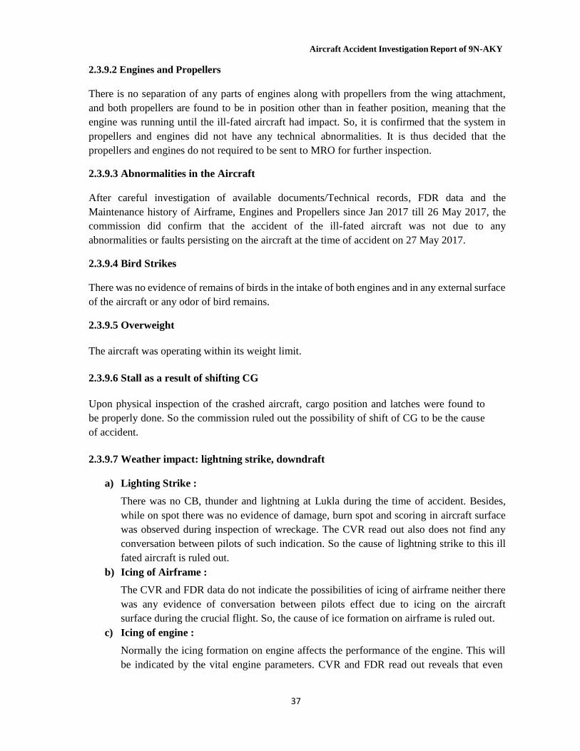
Aircraft Accident Investigation Report of 9N-AKY
37
2.3.9.2 Engines and Propellers There is no separation of any parts of engines along with propellers from the wing attachment, and both propellers are found to be in position other than in feather position, meaning that the engine was running until the ill-fated aircraft had impact. So, it is confirmed that the system in propellers and engines did not have any technical abnormalities. It is thus decided that the propellers and engines do not required to be sent to MRO for further inspection.
2.3.9.3 Abnormalities in the Aircraft
After careful investigation of available documents/Technical records, FDR data and the Maintenance history of Airframe, Engines and Propellers since Jan 2017 till 26 May 2017, the commission did confirm that the accident of the ill-fated aircraft was not due to any abnormalities or faults persisting on the aircraft at the time of accident on 27 May 2017.
2.3.9.4 Bird Strikes
There was no evidence of remains of birds in the intake of both engines and in any external surface of the aircraft or any odor of bird remains.
2.3.9.5 Overweight
The aircraft was operating within its weight limit.
2.3.9.6 Stall as a result of shifting CG
Upon physical inspection of the crashed aircraft, cargo position and latches were found to be properly done. So the commission ruled out the possibility of shift of CG to be the cause of accident.
2.3.9.7 Weather impact: lightning strike, downdraft
a) Lighting Strike :
There was no CB, thunder and lightning at Lukla during the time of accident. Besides, while on spot there was no evidence of damage, burn spot and scoring in aircraft surface was observed during inspection of wreckage. The CVR read out also does not find any conversation between pilots of such indication. So the cause of lightning strike to this ill fated aircraft is ruled out.
b) Icing of Airframe :
The CVR and FDR data do not indicate the possibilities of icing of airframe neither there was any evidence of conversation between pilots effect due to icing on the aircraft surface during the crucial flight. So, the cause of ice formation on airframe is ruled out.
c) Icing of engine :
Normally the icing formation on engine affects the performance of the engine. This will be indicated by the vital engine parameters. CVR and FDR read out reveals that even

Aircraft Accident Investigation Report of 9N-AKY
38
during the last flight the engine parameters fluctuation and power degradation was not noticed, neither any such conversation in CVR read out between pilots is noticed. The impact site also does not indicate the sign of engine failure, fall or sudden direction change as result of icing on engine. So, the icing on engine is ruled out.
2.3.9.8 Pilot incapacitation and cross control issue
No Signs of Pilot incapacitation were observed. However, CVR data indicates that on the last moment of the flight PIC told to the First Officer – "do not pull too much." That indicates that both the crew were operating the controls at the last minute.
2.3.9.9 Unlawful interference and explosives
No Signs of Unlawful Interference or Explosives were observed by the commission.
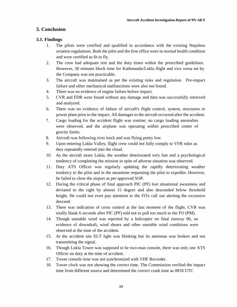
Aircraft Accident Investigation Report of 9N-AKY
39
3. Conclusion 3.1. Findings
1. The pilots were certified and qualified in accordance with the existing Nepalese aviation regulations. Both the pilot and the first office were in normal health condition and were certified as fit to fly.
2. The crew had adequate rest and the duty times within the prescribed guidelines. However, 30 minutes block time for Kathmandu/Lukla flight and vice versa set by the Company was not practicable.
3. The aircraft was maintained as per the existing rules and regulation. Pre-impact failure and other mechanical malfunctions were also not found.
4. There was no evidence of engine failure before impact. 5. CVR and FDR were found without any damage and data was successfully retrieved
and analyzed. 6. There was no evidence of failure of aircraft's flight control, system, structures or
power plant prior to the impact. All damages to the aircraft occurred after the accident. 7. Cargo loading for the accident flight was routine; no cargo loading anomalies
were observed, and the airplane was operating within prescribed center of gravity limits.
8. Aircraft was following river track and was flying pretty low. 9. Upon entering Lukla Valley, flight crew could not fully comply to VFR rules as
they repeatedly entered into the cloud. 10. As the aircraft nears Lukla, the weather deteriorated very fast and a psychological
tendency of completing the mission in spite of adverse situation was observed. 11. Duty ATS Officer was regularly updating the rapidly deteriorating weather
tendency to the pilot and in the meantime requesting the pilot to expedite. However, he failed to close the airport as per approved SOP.
12. During the critical phase of final approach PIC (PF) lost situational awareness and deviated to the right by almost 15 degree and also descended below threshold height. He could not even pay attention to the FO's call out alerting the excessive descend.
13. There was indication of cross control at the last moment of the flight. CVR was totally blank 6 seconds after PIC (PF) told not to pull too much to the FO (PM).
14. Though unstable wind was reported by a helicopter on final runway 06, no evidence of downdraft, wind shears and other unstable wind conditions were observed at the time of the accident.
15. At the accident site ELT light was blinking but its antennae was broken and not transmitting the signal.
16. Though Lukla Tower was supposed to be two-man console, there was only one ATS Officer on duty at the time of accident.
17. Tower console time was not synchronized with VHF Recorder. 18. Tower clock was not showing the correct time. The Commission verified the impact
time from different source and determined the correct crash time as 0818 UTC
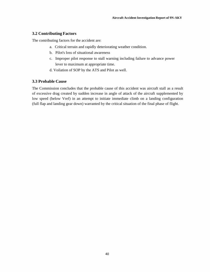
Aircraft Accident Investigation Report of 9N-AKY
40
3.2 Contributing Factors
The contributing factors for the accident are:
a. Critical terrain and rapidly deteriorating weather condition.
b. Pilot's loss of situational awareness
c. Improper pilot response to stall warning including failure to advance power
lever to maximum at appropriate time.
d. Voilation of SOP by the ATS and Pilot as well.
3.3 Probable Cause
The Commission concludes that the probable cause of this accident was aircraft stall as a result of excessive drag created by sudden increase in angle of attack of the aircraft supplemented by low speed (below Vref) in an attempt to initiate immediate climb on a landing configuration (full flap and landing gear down) warranted by the critical situation of the final phase of flight.
Aircraft Accident Investigation Report of 9N-AKY
41
4. Recommendations
4.1 Civil Aviation Authority of Nepal and Airline Operators
1. Launch Voluntary Reporting System as a part of the regular Aviation Safety Campaign
emphasizing a non-punitive environment so that unsafe behavior of all aviation personnel including pilots, ATS personnel and maintenance staffs are brought into notice in time.
2. Increased stress and fatigue as a result of present air traffic congestion in TIA and its direct
impact to the pilots’ proficiency also be taken into consideration while assigning flights
to the flight crews and remedial action be initiated as necessary.
4.2 Goma Air Pvt. Ltd. 1. Review and strengthen Company Training Policy and Training Program of the flight crews
emphasizing on airport based training incorporating unforeseen situations including effective response to the stall warning and pilot’s call out in simulator training.
2. Review the Airline's Operation Manual and SOP incorporating stabilized point and committed point in the approach procedure of the Category C stall airfield so that a clear-cut guidance is available to the flight crews whether to continue or divert the flight.
3. Develop a mechanism to monitor and ensure compliance to the provisions of VFR flights, SOP and other relevant safety directives by the flight crew.
4. Review the block time of each sector providing enough ground time for each flight. 5. GOMA air should enhance the flight dispatcher’s capability to enable them to fulfill
their responsibilities as per the provision of company SOP. 6. GOMA air should review and further strengthen the effective implementation of SMS
process more importantly based on reporting system by crews. 7. In view of available number of fleet, it is important that GOMA air should identify the
requirement of crew size to meet the flight requirement, so accordingly they should be trained to identify the hazard, changes in system, operational environment and consequential safety risk
4.3 Civil Aviation Authority of Nepal (CAAN) 1. Ensure that irrespective of the air traffic volume, assigned numbers of ATS personnel are
manned in each shift of an ATS Unit (AFIS Tower). 2. Depending upon the volume of air traffic, declare the minimum experience required for
an ATS personnel in each shift at a particular station. 3. In participation with the management of local hospital or health post close to the busy
airport like Lukla, CAAN should initiate to upgrade their essential emergency medical facilities such as readiness of oxygen and ventilators.
4. Rescue and Fire Service at Lukla Airport be strengthened with adequate manpower and equipment.
Aircraft Accident Investigation Report of 9N-AKY
42
5. Encourage on the spot inspection focusing on the critical safety areas including violation of SOP, proper CRM, CFIT, and ensure effective enforcement mechanism.
6. Immediate action be initiated to set up and maintain essential MET equipment at Lukla Tower including the display of the real-time surface wind information of the runway threshold.
7. Owing to the critical approach at Lukla immediate action be initiated for the possible extension of the runway threshold further to the South.
8. Recognizing the critical situation that might arise as a result of sudden and rapid lifting of fog or cloud during final approach, it is recommended to install an appropriate visual aid or lighting system at Lukla runway.
4.4 Ministry of Culture, Tourism and Civil Aviation 1. Continuous Coordination and monitoring with CAAN for the effective implementation
of the safety recommendations issued by investigation commissions. 2. Sufficient resources of finance, personnel and technical experts should be made
available so that the investigation of an airplane accident can be performed effectively and timely.
3. An independent and permanent body should be established for the aircraft accident and
incident investigation purpose. The proposed Body should also be given the responsibility
of monitoring the implementation of the Safety recommendations issued by Accident
Investigation Commissions in the past and also act as the research body for the safety
enhancement in the aviation sector.