FINAL FEASIBILITY REPORT FOR ETHYLENE DERIVATIVE...
147
FINAL FEASIBILITY REPORT FOR ETHYLENE DERIVATIVE PROJECT AT PARADIP CLIENT INDIAN OIL CORPORATION LIMITED PARADIP PREPARED BY ENGINEERS INDIA LIMITED NEW DELHI EIL JOB No: A360 Contract Dated 25-September-2012 REPORT No: A360-RP-0241-0001 JANUARY 2015
Transcript of FINAL FEASIBILITY REPORT FOR ETHYLENE DERIVATIVE...

FINAL FEASIBILITY REPORT FOR
ETHYLENE DERIVATIVE PROJECT AT PARADIP
CLIENT INDIAN OIL CORPORATION LIMITED
PARADIP
PREPARED BY ENGINEERS INDIA LIMITED
NEW DELHI
EIL JOB No: A360 Contract Dated 25-September-2012
REPORT No: A360-RP-0241-0001 JANUARY 2015

Feasibility Report for Ethylene
Derivative Project at Paradip
Document No.
A360-RP-0241-0001 Rev C
Page 2 of 147
Template No. 5-0000-0001-T2 Rev. C
Copyright EIL – All rights reserved
Copyright
This document is copyright protected by EIL and is produced for the client Indian Oil Corporation
Limited.
Neither this document nor any extract from it may be produced, stored or transmitted in any form
for any purpose by any party without prior written permission from EIL.
Request for additional copies or permission to reproduce any part of the document for any
commercial purpose should be addressed as shown below:
GM (PDD)
Engineers India Limited
Research and Development Complex
Gurgaon-122001
India
Telephone: 0124-3803701
EIL reserves the right to initiate appropriate legal action against any unauthorized use of its
Intellectual Property by any entity.
C

Feasibility Report for Ethylene
Derivative Project at Paradip
Document No.
A360-RP-0241-0001 Rev C
Page 3 of 147
Template No. 5-0000-0001-T2 Rev. C
Copyright EIL – All rights reserved
Table of Contents
Section Content Page No.
1.0 Executive Summary 9
2.0 Introduction 23
3.0 Scope 26
4.0 Design Basis 28
5.0 Market Study 37
6.0 Project Location 39
7.0 Project Description 42
7.1 Project Configuration 44
7.2 Technology Options 60
7.3 Process Description 63
7.4 Material Balance 78
7.5 Utilities Description 82
7.6 Offsite Description 99
7.7 Logistics 112
8.0 Environmental Considerations 117
9.0 Project Implementation and Schedule 137
10.0 Project Cost Estimate 139
11.0 Financial Analysis 141
12.0 Recommendations 143

Feasibility Report for Ethylene
Derivative Project at Paradip
Document No.
A360-RP-0241-0001 Rev C
Page 4 of 147
Template No. 5-0000-0001-T2 Rev. C
Copyright EIL – All rights reserved
Annexures
Annexure Content
I Signed Design Basis of the FR II Block Flow Diagram – Configuration-1 III Block Flow Diagram – Configuration-2 IV Block Flow Diagram – Configuration-3 V Block Flow Diagram – Configuration-4 VI Block Flow Diagram – Configuration-5A VII Block Flow Diagram – Configuration-5B VIII Block Flow Diagram – Configuration-5C/5E IX Block Flow Diagram – Configuration-5D X Block Flow Diagram – Configuration-5F XI Block Flow Diagram – Configuration-5G XII Block Flow Diagram – Configuration-6/6A/6B/6C XIII Capital cost estimate and financial analysis
XIV Preliminary Process Flow Diagram XV Overall Plot Plan Configuration-6C XVI Project Implementation and Schedule XVII Equipment List Configuration-6C XVIII List of Catalyst and Chemicals
C

Feasibility Report for Ethylene
Derivative Project at Paradip
Document No.
A360-RP-0241-0001 Rev C
Page 5 of 147
Template No. 5-0000-0001-T2 Rev. C
Copyright EIL – All rights reserved
XIX List of additional hardware –ERU
XX Configuration-4a & 4b summary XXI Ethylene Recovery Unit
Figures and Tables
Figures
Figure No. Description
7.5.1.1 Recirculating Cooling Water System
7.5.5.1 Condensate Polishing Unit
Tables Table no. Description
1.4.1 Original Project Configuration envisaged
1.4.2 Updated Project Configuration
1.5.1A/B Material balance
1.8.1 Basis of Financial Analysis
1.9.2.1 List of Sensitivity Cases
1.10.1 Product Prices
1.10.2 Feed Prices
1.10.3 Utility Prices
1.11.1 Product Sale Split
1.12.1 Economic Summary
1.12.2 Sensitivity Analysis
1.12.3 Sensitivity Analysis
4.24.1 Product Prices
4.24.2 Feed Prices
C

Feasibility Report for Ethylene
Derivative Project at Paradip
Document No.
A360-RP-0241-0001 Rev C
Page 6 of 147
Template No. 5-0000-0001-T2 Rev. C
Copyright EIL – All rights reserved
4.26.3 Utility Prices
4.27.2.1 Revised Feed, Product, Utility prices
Table no. Description
4.27.2.1 Revised Feed, Product, Utility prices
4.27.3.1 Updated Product prices
4.27.3.2 Updated Feed prices
4.27.3.3 Updated Utility prices
6.1.1 Estimated Plot Area
7.1.2.1 Ethylene Quality
7.1.2.2 Propylene Quality
7.1.2.3 Benzene Quality
7.1.2.4 Vinyl Acetate Quality
7.1.2.5 Ethylidene-Norbornene (ENB) Quality
7.1.2.6 Extender Oil Quality
7.1.2.7 Oxygen Quality
7.1.2.8 Oxygen Quality
7.1.2.9 Hydrogen Quality
7.1.2.10 Import Ethylene Dichloride Quality
7.1.2.11 Nitrogen Quality
7.1.3.1 Original Project Configuration envisaged
7.1.3.2 Updated Project Configuration
7.1. 4.1a EVA/LDPE Grades
7.1.4.2a EPDM Grades
7.1.4.3a PVC Grades
7.1.4.4a Styrene Monomer specifications
7.1.4.5a MEG specifications
Feasibility Report for Ethylene
Derivative Project at Paradip
Document No.
A360-RP-0241-0001 Rev C
Page 7 of 147
Template No. 5-0000-0001-T2 Rev. C
Copyright EIL – All rights reserved
7.2.1 Process Licensors
7.4.1 a/b/c Overall Material balance
Table no. Description
7.5.1.1a/b Cooling Water requirement
7.5.1.2a/b Cooling Water System Configuration
7.5.2.1 Complex Power requirement
7.5.2.2 Complex Steam requirement
7.5.2.3 Complex Steam generation
7.5.2.4 Complex Power generation
7.5.2.5 Complex CPP Configuration
7.5.2.6 Complex CPP Configuration
7.5.2.7 Complex CPP Configuration
7.5.2.8 Complex CPP Configuration
7.5.2.9 Complex CPP Configuration
7.5.3.1 Complex Treated Raw Water Consumption
7.5.3.2 Complex Treated Raw Water Consumption
7.5.4.1 RO-DM Water System Details
7.5.5.1 Condensate Polishing Unit Details
7.5.6.1 Compressed Air & Cryogenic Nitrogen
7.5.6.2 Compressed Air & Cryogenic Nitrogen
7.5.6.3 Compressed Air & Cryogenic Nitrogen
7.6.1.4.a Offsite facilities Config 1/1a
7.6.1.4.b Offsite facilities Config 2
7.6.1.4.c Offsite facilities Config 3
7.6.1.4.d Offsite facilities Config 4
7.6.1.4.e Offsite facilities Config 5a
7.6.1.4.f Offsite facilities Config 5b

Feasibility Report for Ethylene
Derivative Project at Paradip
Document No.
A360-RP-0241-0001 Rev C
Page 8 of 147
Template No. 5-0000-0001-T2 Rev. C
Copyright EIL – All rights reserved
7.6.1.4.g Offsite facilities Config 5c/5e
7.6.1.4.h Offsite facilities Config 5d
Table no. Description
7.6.1.4.i Offsite facilities Config 5f
7.6.1.4.j Offsite facilities Config 5g
7.6.1.4.k Offsite facilities Config 6
7.6.1.4.l Offsite facilities Config 6a
7.6.1.4.m Offsite facilities Config 6b
7.6.1.4.n Offsite facilities Config 6c
7.6.1.5a/b/c Interconnecting Pipelines summary
7.7.1 Despatch mode for Feed, Products and Internal streams
8.2.1 Effluent Summary 1/1a
8.2.2 Effluent Summary 2
8.2.3 Effluent Summary 3
8.2.4 Effluent Summary 4
8.2.5 Effluent Summary 5a
8.2.6 Effluent Summary 5b
8.2.7 Effluent Summary 5c/e
8.2.8 Effluent Summary 5d
8.2.9 Effluent Summary 5f
8.2.10 Effluent Summary 5g
8.2.11 Effluent Summary 6/6a/6b/6c
8.3.1 SO2 Emission
8.3.2 SO2 Emission
8.6.1.1 National Ambient Air Quality Standards 2009
8.6.2.1 Standards for atmospheric storage tanks for petrochemical products
C
C

Feasibility Report for Ethylene
Derivative Project at Paradip
Document No.
A360-RP-0241-0001 Rev C
Page 9 of 147
Template No. 5-0000-0001-T2 Rev. C
Copyright EIL – All rights reserved
8.6.3.1 Hazardous Air Pollutant (HAP) Concentrations 8.6.3.2 Frequency and Schedule of Monitoring 8.6.4.1 Method of Measurement of emissions 8.6.5.1 Gaseous effluent for ER & MEG BLock (For Configuration- 6C) 8.7.1 Ambient Air Quality Standards in respect of Noise 8.8.1.1 Liquid Effluent details for Configuration-6C 8.9.1.1 Solid Effluent for configuration-6C
C

Feasibility Report for Ethylene
Derivative Project at Paradip
Document No.
A360-RP-0241-0001 Rev C
Page 10 of 147
Template No. 5-0000-0001-T2 Rev. C
Copyright EIL – All rights reserved
SECTION 1.0
EXECUTIVE SUMMARY

Feasibility Report for Ethylene
Derivative Project at Paradip
Document No.
A360-RP-0241-0001 Rev C
Page 11 of 147
Template No. 5-0000-0001-T2 Rev. C
Copyright EIL – All rights reserved
1.1 INTRODUCTION
The growth plan for Indian Oil Corporation Limited (IOCL), envisages operating the grass root refinery at Paradip with a crude processing capacity of 15 MMTPA. The refinery configuration has a high severity FCCU (INDMAX) unit with a capacity of 4.2 MMTPA which is presently under implementation. The off gas generated in the high severity mode contains a significant potential of ethylene which can be recovered for value addition. Potential exists to explore the possibilities of setting up of an Ethylene derivative complex to produce high value polymers / petrochemicals such as EVA/LDPE, EPDM, PVC, Styrene, MEG etc by considering feed stocks available from the grass root refinery such as FCC off gas , Oxygen and Propylene. Balance of the feed stock is considered as merchant purchase.
Indian Oil Corporation Limited has engaged the services of Engineers India Limited (EIL) to prepare Feasibility report (+/- 30 % Cost Estimate Accuracy) for the proposed ethylene derivative complex for IOCL to ascertain the technical aspects and take investment decision based on its viability. This report pertains to investment study covering briefly project configuration, project description, execution schedule, cost estimate, financial analysis, to enable IOCL in taking investment decision
1.2 PROJECT LOCATION
The project is to be located as part of the existing refinery complex of IOCL at Town/City: Abhaychandrapur, Paradip, Distt: Jagatsinghpur, Orissa. The site is located at Latitude 20° 15’ 20” and Longitude 86° 36’ 00”. The site is at minimum 3.91 m above Indian mean sea level (IMSL) which corresponds to the site recorded flood level
The site for new facilities coming in Ethylene Derivative complex shall be located within the boundary wall of the existing refinery facilities at Paradip, Orissa.
Since the proposed FR for Ethylene derivative complex at Paradip is being considered as part of the existing refinery complex, available area within the complex boundary, as earmarked by IOCL, has been considered for the expansion.
1.3 FEED SPECIFICATION
It is proposed to utilize the feed streams available from the refinery as under.
1.3.1 FCC Off gas. 1.3.1.1 Ethylene is recovered from the FCC off gas in a Ethylene Recovery Unit (ERU),
licensed / designed by ABB Lummus. The ABB Lummus package of ERU is designed for 180 KTPA of 99.5 wt % Ethylene.
1.3.1.2 For the proposed Ethylene Derivative complex, 220 KTPA of Polymer grade Ethylene (99.9 mole % ethylene content) is to be made available.
1.3.1.3 The present ERU design needs to be revisited to make it suitable for generating 220 KTPA of Polymer grade ethylene. However, directional requirements in design corresponding to augmentation have been considered in the FR. List of additional hardware, as suggested by Licensor, for generating 180 KTPA of Polymer grade ethylene is attached as Annexure XIX.
B
C

Feasibility Report for Ethylene
Derivative Project at Paradip
Document No.
A360-RP-0241-0001 Rev C
Page 12 of 147
Template No. 5-0000-0001-T2 Rev. C
Copyright EIL – All rights reserved
1.3.1.4 For the purpose of the FR, it is considered that ERU will produce 220 KTPA of Polymer grade Ethylene.
1.3.1.5 Ethylene from the upstream ERU will be used as feed to the downstream units of the Ethylene Derivative Complex.
1.3.1.6 Ethylene Recovery Unit (ERU) is considered as a part of the ethylene derivative complex and is included in project cost estimate.
1.3.1.7 ERU is designed by M/S Lummus (CB&I) to process FCC off gas after DEA wash (Absorber within INDMAX unit, regenerator in Paradip Refinery). IOCL has replaced Off gas Amine Scrubber solvent from DEA to MDEA. Hence another standalone Absorber-Regenerator system with DEA as solvent, to be installed upstream of ERU within Ethylene Derivative Complex.
1.3.2 Propylene.
1.3.2.1 Propylene required for the downstream unit, as the case may be, will come from the upstream Propylene Recovery Unit (PRU) of the refinery, this PRU is excluded from the scope of FR. Propylene purity available from this PRU is 93 wt%.
1.3.2.2 The purity of this Propylene is further enhanced to 99.5 wt% in another PRU, which has been envisaged as part of the C2 derivative complex.
Balance of the feedstock such as Vinyl Acetate Monomer (VAM) , Benzene, Oxygen, Ethylidene-Norbornene (ENB), Brine, Ethylene Di Chloride (EDC), are considered as merchant purchase and same shall be made available at Ethylene derivative complex battery limit, by IOCL. Hydrogen would be sourced from Paradip refinery. With this feed stock, several configuration were explored for the Proposed Ethylene Derivative complex. The details of the various configuration along with the unit capacities, material balance, utility balance, product slate are covered in Section 7, Project Description, of the Feasibility report.
1.4 PROJECT CONFIGURATION: Following configurations were identified in the scope of work.
Table: 1.4.1: Original Project Configuration Envisaged
Conf Unit Capacity
1 ERU EVA / LDPE
230 KTPA of Ethylene 260 KTPA of Polymer Product (EVA=130 KTPA, LDPE=130 KTPA)
2 a ERU EVA / LDPE EPDM
230 KTPA of Ethylene 185 KTPA of Polymer Product (EVA=115 KTPA, LDPE=70 KTPA) 120 KTPA of EPDM
2 b ERU EVA / LDPE EPDM
230 KTPA of Ethylene 210 KTPA of Polymer Product (EVA=120 KTPA, LDPE=90 KTPA) 75 KTPA of EPDM
3 ERU PVC
230 KTPA of Ethylene 500 KTPA of PVC
4 ERU EB/SM EPDM
230 KTPA of Ethylene 600 KTPA of Styrene 100 KTPA of EPDM
However, in the course of the study and as an outcome of several meeting held between IOCL and EIL, additional thirteen number of configurations were examined with the intent of
C
Feasibility Report for Ethylene
Derivative Project at Paradip
Document No.
A360-RP-0241-0001 Rev C
Page 13 of 147
Template No. 5-0000-0001-T2 Rev. C
Copyright EIL – All rights reserved
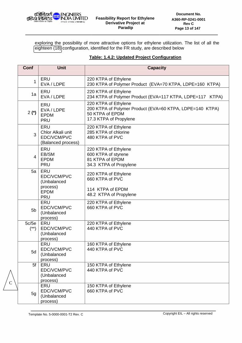
exploring the possibility of more attractive options for ethylene utilization. The list of all the eighteen (18) configuration, identified for the FR study, are described below
Table: 1.4.2: Updated Project Configuration
Conf
Unit Capacity
1 ERU EVA / LDPE
220 KTPA of Ethylene 230 KTPA of Polymer Product (EVA=70 KTPA, LDPE=160 KTPA)
1a ERU EVA / LDPE
220 KTPA of Ethylene 234 KTPA of Polymer Product (EVA=117 KTPA, LDPE=117 KTPA)
2 (*)
ERU EVA / LDPE EPDM PRU
220 KTPA of Ethylene 200 KTPA of Polymer Product (EVA=60 KTPA, LDPE=140 KTPA) 50 KTPA of EPDM 17.3 KTPA of Propylene
3
ERU Chlor Alkali unit EDC/VCM/PVC (Balanced process)
220 KTPA of Ethylene 285 KTPA of chlorine 480 KTPA of PVC
4
ERU EB/SM EPDM PRU
220 KTPA of Ethylene 600 KTPA of styrene 81 KTPA of EPDM 34.3 KTPA of Propylene
5a ERU EDC/VCM/PVC (Unbalanced process) EPDM PRU
220 KTPA of Ethylene 660 KTPA of PVC 114 KTPA of EPDM 48.2 KTPA of Propylene
5b
ERU EDC/VCM/PVC (Unbalanced process)
220 KTPA of Ethylene 660 KTPA of PVC
5c/5e (**)
ERU EDC/VCM/PVC (Unbalanced process)
220 KTPA of Ethylene 440 KTPA of PVC
5d
ERU EDC/VCM/PVC (Unbalanced process)
160 KTPA of Ethylene 440 KTPA of PVC
5f ERU EDC/VCM/PVC (Unbalanced process)
150 KTPA of Ethylene 440 KTPA of PVC
5g
ERU EDC/VCM/PVC (Unbalanced process)
150 KTPA of Ethylene 660 KTPA of PVC
C

Feasibility Report for Ethylene
Derivative Project at Paradip
Document No.
A360-RP-0241-0001 Rev C
Page 14 of 147
Template No. 5-0000-0001-T2 Rev. C
Copyright EIL – All rights reserved
6/6A / 6B(***)
ERU MEG
220 KTPA of Ethylene 372 KTPA of MEG
6C (****)
ERU MEG
220 KTPA of Ethylene 372 KTPA of MEG
4A/4B (*****)
ERU EB/SM
180 KTPA of Ethylene 600 KTPA of Styrene
(*) Based on the deliberation between EIL/IOCL and LYB/EMCTL Configuration 2a and 2b was rationalized to Configuration 2. (**) Configuration 5e is similar to 5c, except that plot provision for an additional future train of PVC (220 KTPA PVC product) has been considered in Configuration 5e. (***) Configuration 6, 6A, 6B differ with respect to the CPP configuration, utility block configuration and number of interconnecting pipelines. Material balance is same for all the four configurations. (****) Configuration-1,1a,2,3,4,5a,5b,5c/e,5f,5g,6,6a,6b were presented to IOCL, wherein Configuration-6B had emerged as the configuration with highest IRR, highest NPV, lowest total OPEX and minimum CAPEX and was therefore recommended by EIL for further pursue at DFR stage. IOCL reviewed and accepted the above finding and chose to further improve the same as Configuration-6C. Material Balance for 6C is the same as that of Configuration-6, 6A, 6B. (*****) Configuration 4A, 4B was additionally developed as standalone styrene project comprising of ERU, EB/SM as designed by CB&I Lummus. Configuration-4A has its independent Utility & Offsite facilities ,as was the basis adopted in Configurations 1,1A ,2,3,4, 5 A-G. Configuration-4B has integration with Paradip refinery w.r.t. Utilities comprising of HSFO, Treated Raw Water, DM, BFW, IA, PA, N2, VHP Steam and Power completely sourced from the refinery as adopted in Configuration-6C. Refer Annexure-XX wherein required comparison of 4A,4B vis a vis Configuration- 6C has been done.
1.5 MATERIAL BALANCE
The material balance for all the configuration of the proposed ethylene derivative complex is tabulated below:
Table 1.5.1a Material balance
Sl No Feed
Quantity (KTPA)
Config 3
1 OFF GAS FROM FCC 552.8
2 NaCl SALT 490.8
3 OXYGEN 64
4 CAUSTIC 1.9
Sl No Products
Quantity (KTPA)
Config 3
1 C2 PURGE 21.4
2 C3 PRODUCT 24.2
3 PVC 475.2
4 CAUSTIC 320.9
5 FUEL GAS 261.9
Sl No Feed Quantity (KTPA)
Conf-1 / 1a Conf-2
1 OFF GAS FROM FCC 552.8 / 552.8 552.8
2 VINYL ACETATE 10.7 / 18.2 9.09
3 PROPYLENE (93wt%) NA 18.5
4 ENB (DIENE) NA 2.5
5 EXTENDER OIL NA 4.1
6 HYDROGEN NA 0.002
Sl No Products Quantity (KTPA)
Conf-1 / 1a Conf-2
1 C2 PURGE 21.4 / 21.4 21.4
2 C3 PRODUCT 24.2 / 24.1 24.2
3 EVA 68.4 / 116.8 60
4 LDPE 159.1 / 116.9 140
5 FUEL GAS 261.9 / 261.9 261.1
6 EPDM NA 50
B
C

Feasibility Report for Ethylene
Derivative Project at Paradip
Document No.
A360-RP-0241-0001 Rev C
Page 15 of 147
Template No. 5-0000-0001-T2 Rev. C
Copyright EIL – All rights reserved
No Feed
Quantity (KTPA)
Conf-5b Conf-5c/e Conf-5d Conf-5f Conf-5g
1 OFF GAS FROM FCC 552.8 552.8 402.1 251.3 376.9
2 CHLORINE 1.3 0.9 0.9 0.9 1.3
3 OXYGEN 90.1 60 60 60 90.1
4 IMPORT EDC 539.9 359.9 359.9 359.9 539.9
Sl No Products Quantity (KTPA)
Conf-5b Conf-5c/e Conf-5d Conf-5f Conf-5g
1 C2 PURGE 21.4 21.4 15.6 9.7 14.6
2 C3 PRODUCT 24.2 24.2 17.6 11 16.5
3 PVC 660 440 440 440 660
4 ETHYLENE
(FOR SALE) 70.8 120.5 60.5 NA NA
5 FUEL GAS 261.9 261.9 188.9 116 176.8
Table 1.5.1b Material balance
NA: Not applicable
Sl No Feed Quantity (KTPA)
Config 4
1 OFF GAS FROM FCC 552.8
2 PROPYLENE (93wt%) 36.7
3 ENB (DIENE) 5.2
4 EXTENDER OIL 11.7
5 BENZENE 467.7
6 HYDROGEN 0.0032
Sl No Products Quantity (KTPA)
Config 4
1 C2 PURGE 21.4
2 C3 PRODUCT 24.2
3 EPDM 81
4 STYRENE 600
5 BT BY PRODUCT 14.72
6 FUEL GAS 261.07
7 COMPRESSED OFF
GAS 21.92
Sl No Feed Quantity (KTPA)
Config 5a
1 OFF GAS FROM FCC 552.8
2 PROPYLENE (93wt%) 51.5
3 ENB (DIENE) 7.3
4 EXTENDER OIL 16.4
5 CHLORINE 1.3
6 OXYGEN 90.1
7 IMPORT EDC 539.9
8 HYDROGEN 0.0046
Sl No Products Quantity (KTPA)
Config 5a
1 C2 PURGE 21.4
2 C3 PRODUCT 24.2
3 EPDM 114
4 PVC 660
5 FUEL GAS 261.1
Sl No Feed
Quantity (KTPA)
Config 6 / 6A / 6B/6C
1 FF GAS FROM FCC 552.8
2 NITROGEN 1.71
3 OXYGEN 229
Sl No Products
Quantity (KTPA)
Config 6/6A/6B/6C
1 C2 PURGE 21.4
2 C3 PRODUCT 24.2
3 MEG 371.7
4 DEG 26.4
5 TEG 1.18
6 FUEL GAS 261.9
C

Feasibility Report for Ethylene
Derivative Project at Paradip
Document No.
A360-RP-0241-0001 Rev C
Page 16 of 147
Template No. 5-0000-0001-T2 Rev. C
Copyright EIL – All rights reserved
1.6 UTILITY BALANCE
The utility requirement for all the configuration of the proposed ethylene derivative complex assuming 100% captive generation was prepared and discussed with IOCL. IOCL reviewed and informed that Ethylene Derivative complex will only receive HSFO and Treated Raw Water (TRW) from the Refinery for all the configurations. Additionally Ethylene derivative complex will also receive the following streams from Refinery: a) IA, PA and N2 for Configuration 6 b) IA, PA, N2 and DM water for Configuration 6A and c) IA, PA, N2, DM, BFW, VHP Steam and Power for Configuration 6B. An STG is still
configured into the complex. d) IA, PA, N2, DM, BFW, VHP Steam and Power for Configuration 6C. There is no CPP
in the complex.
RLNG is used as a fuel for ethylene derivative complex considering potential availability of natural gas at Paradip by the time ethylene derivative complex is implemented. For the purpose of this FR, RLNG is considered to be made available at the Ethylene derivative complex battery limit by IOCL. The following dedicated captive utility systems have been provided for the Configuration of the Ethylene derivative complex except as specifically excluded.
Captive Power Plant except in Configuration-6C.
Cooling water system
Demineralised Water system except in Configuration-6A, 6B, 6C.
Condensate Polishing unit except in Configuration-1,1a, 2, 3.
Compressed air and Cryogenic Nitrogen system except in Configuration-6A, 6B, 6C. As informed by IOCL, C2 derivative complex and PP complex will share a single flare system which shall be located within PP complex. Augmentation of PP flare system needs to be carried out to make it suitable for C2 derivative complex flare load as well. Hence, no plot or hardware has been allocated for the flare system of C2 derivative complex. However, cost of Flare system for Ethylene Derivative Complex have been developed for differential flare load (that is, differential of PP + C2 derivative flare load and only PP flare load) which would then be passed between Projects internally by IOCL.
1.7 OFFSITE FACILITY
Offsite storage facilities include storage vessels/tanks/sphere for feed, intermediates feed, Off spec intermediate feed & products, pumping facilities, loading/unloading facilities and auxiliary facilities like boil off gas compression system, emergency vaporization/heating system/vapor recovery system etc. Besides the above, interconnecting pipelines carrying FCC off gas, Oxygen, Propylene, TRW, HSFO, RLNG, Fuel gas, Compressed off gas, EDC, VHP steam, DM water, Boiler Feed water, to/from ethylene derivative complex to refinery are also envisaged in this complex. The offsite storage facilities for the complex will be designed to store the products based on upstream and downstream shutdown. In general finished solid products will have storage capacity adequate enough to store 30 days unit production at 100% throughput. In general intermediate products will have storage equivalent to 5 days unit production at 100% throughput. Feed and liquid products will normally have storage capacity adequate enough to store 15 days unit production at 100% through put.
C
Feasibility Report for Ethylene
Derivative Project at Paradip
Document No.
A360-RP-0241-0001 Rev C
Page 17 of 147
Template No. 5-0000-0001-T2 Rev. C
Copyright EIL – All rights reserved
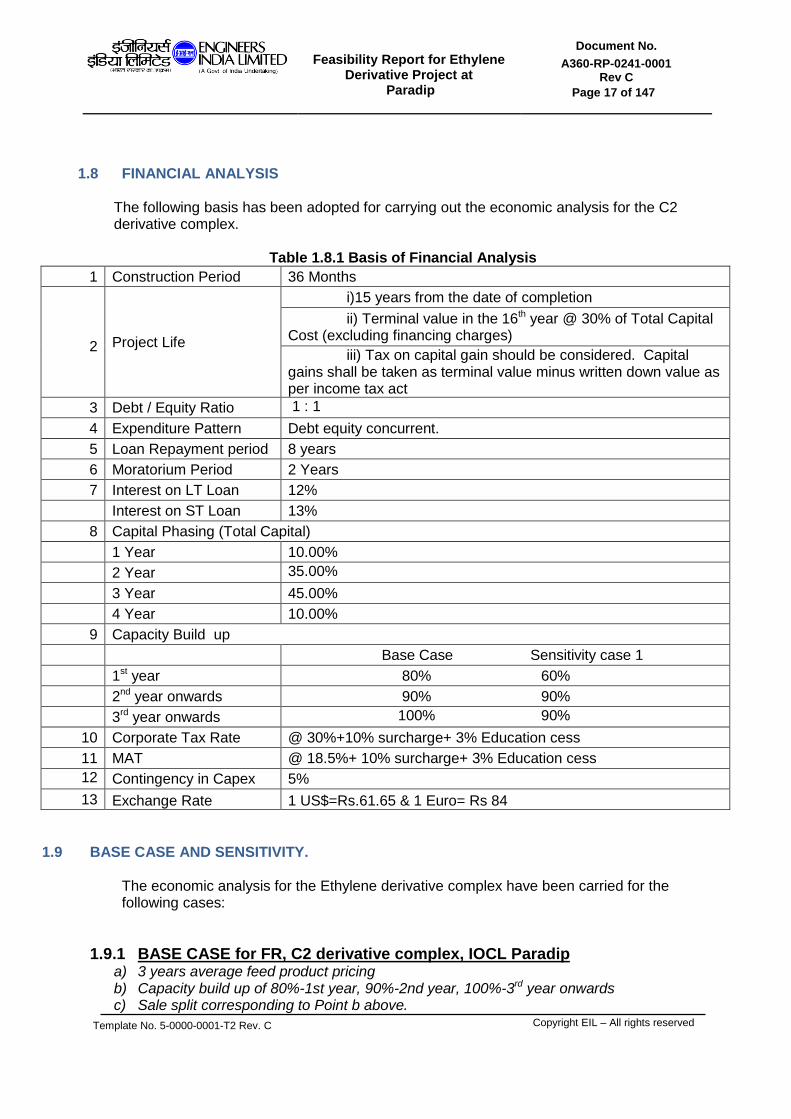
1.8 FINANCIAL ANALYSIS
The following basis has been adopted for carrying out the economic analysis for the C2 derivative complex.
Table 1.8.1 Basis of Financial Analysis
1 Construction Period 36 Months
2 Project Life
i)15 years from the date of completion
ii) Terminal value in the 16th year @ 30% of Total Capital Cost (excluding financing charges)
iii) Tax on capital gain should be considered. Capital gains shall be taken as terminal value minus written down value as per income tax act
3 Debt / Equity Ratio 1 : 1
4 Expenditure Pattern Debt equity concurrent.
5 Loan Repayment period 8 years
6 Moratorium Period 2 Years
7 Interest on LT Loan 12%
Interest on ST Loan 13%
8 Capital Phasing (Total Capital)
1 Year 10.00%
2 Year 35.00%
3 Year 45.00%
4 Year 10.00%
9 Capacity Build up
Base Case Sensitivity case 1
1st year 80% 60%
2nd year onwards 90% 90%
3rd year onwards 100% 90%
10 Corporate Tax Rate @ 30%+10% surcharge+ 3% Education cess
11 MAT @ 18.5%+ 10% surcharge+ 3% Education cess
12 Contingency in Capex 5%
13 Exchange Rate 1 US$=Rs.61.65 & 1 Euro= Rs 84
1.9 BASE CASE AND SENSITIVITY. The economic analysis for the Ethylene derivative complex have been carried for the following cases:
1.9.1 BASE CASE for FR, C2 derivative complex, IOCL Paradip a) 3 years average feed product pricing b) Capacity build up of 80%-1st year, 90%-2nd year, 100%-3rd year onwards c) Sale split corresponding to Point b above.
Feasibility Report for Ethylene
Derivative Project at Paradip
Document No.
A360-RP-0241-0001 Rev C
Page 18 of 147
Template No. 5-0000-0001-T2 Rev. C
Copyright EIL – All rights reserved
d) EPCM mode of execution.
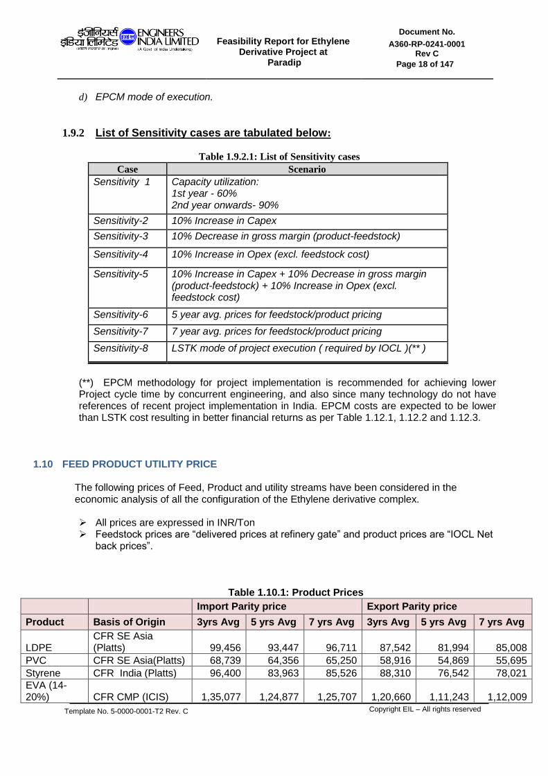
1.9.2 List of Sensitivity cases are tabulated below:
Table 1.9.2.1: List of Sensitivity cases
Case Scenario Sensitivity 1 Capacity utilization:
1st year - 60% 2nd year onwards- 90%
Sensitivity-2 10% Increase in Capex
Sensitivity-3 10% Decrease in gross margin (product-feedstock)
Sensitivity-4 10% Increase in Opex (excl. feedstock cost)
Sensitivity-5 10% Increase in Capex + 10% Decrease in gross margin (product-feedstock) + 10% Increase in Opex (excl. feedstock cost)
Sensitivity-6 5 year avg. prices for feedstock/product pricing
Sensitivity-7 7 year avg. prices for feedstock/product pricing
Sensitivity-8 LSTK mode of project execution ( required by IOCL )(** )
(**) EPCM methodology for project implementation is recommended for achieving lower Project cycle time by concurrent engineering, and also since many technology do not have references of recent project implementation in India. EPCM costs are expected to be lower than LSTK cost resulting in better financial returns as per Table 1.12.1, 1.12.2 and 1.12.3.
1.10 FEED PRODUCT UTILITY PRICE
The following prices of Feed, Product and utility streams have been considered in the economic analysis of all the configuration of the Ethylene derivative complex.
All prices are expressed in INR/Ton Feedstock prices are “delivered prices at refinery gate” and product prices are “IOCL Net
back prices”.
Table 1.10.1: Product Prices
Import Parity price Export Parity price
Product Basis of Origin 3yrs Avg 5 yrs Avg 7 yrs Avg 3yrs Avg 5 yrs Avg 7 yrs Avg
LDPE CFR SE Asia (Platts) 99,456 93,447 96,711 87,542 81,994 85,008
PVC CFR SE Asia(Platts) 68,739 64,356 65,250 58,916 54,869 55,695
Styrene CFR India (Platts) 96,400 83,963 85,526 88,310 76,542 78,021
EVA (14-20%) CFR CMP (ICIS) 1,35,077 1,24,877 1,25,707 1,20,660 1,11,243 1,12,009

Feasibility Report for Ethylene
Derivative Project at Paradip
Document No.
A360-RP-0241-0001 Rev C
Page 19 of 147
Template No. 5-0000-0001-T2 Rev. C
Copyright EIL – All rights reserved
EVA (22-30%) CFR Asia SW (ICIS) 1,45,877 1,34,588 1,34,588 1,30,655 1,20,231 1,20,231
Benzene FOB Korea 78,975 67,497 68,590
Toluene CFR India (Platts) 76,268 65,298 65,725
LPG N.E/Haldia RTP 54365 40839 38287 Ethylene CFR SE Asia 76,969 68,910 71,441 62,506 54,843 57,249
EPDM CFR China (IIPMR) & ICIS 2,10,712 1,88,086 1,81,022 1,91,229 1,70,338 1,63,815
Caustic lye CFR SE Asia 28,963 25,374 25,247
MEG CFR CMP (ICIS) 69,395 59,359 61,710 62,017 52,521 54,746
DEG CFR CMP (ICIS) 69,983 62,496 64,174 62,573 55,489 57,077
TEG FOB Indian Port 1,12,300 1,12,300 1,12,300 1,12,300 1,12,300 1,12,300
C3 product
Propylene content in the stream priced at propylene price, Balance components of the stream priced at LPG price 55,539 42,783 40,231
BT byproduct
The weighted average price of Benzene and toluene in the ratio they are present in the stream 75,550 64,649 65,262
Fuel Gas to OSBL
priced based on the HSFO price with LHV correction
29324.2 25401.8 22702.6
C2 Purge priced based on the HSFO price with LHV correction
37770.8 32718.6 29241.9
Compressed Off Gas
priced based on the HSFO price with LHV correction
57157.6 49512.2 44251.0
Table 1.10.2: Feed Prices
Feed Basis of Origin 3yrs Avg 5 yrs Avg 7 yrs Avg.
FCC Off Gas priced based on the HSFO price with LHV correction
32436.1 28097.4 25111.8
ENB 3.5 times Butadiene NW Europe contract price 4,82,074 4,00,135 3,65,224
93 wt% Propylene LPG RTP plus PRU Opex 55890 43364 40812
EDC CFR SE Asia (Platts) 24,207 24,415 25,549
VAM CFR SE Asia (Platts) 71,153 65,969 71,022
Salt NE Asia delivered (Contract) 4,042 3,936 3,611
Benzene FOB Korea 78,975 67,497 68,590
Oxygen IOCL data provided on 13.6.2013 2,472 2,472 2,472
Table 1.10.3: Utility Prices

Feasibility Report for Ethylene
Derivative Project at Paradip
Document No.
A360-RP-0241-0001 Rev C
Page 20 of 147
Template No. 5-0000-0001-T2 Rev. C
Copyright EIL – All rights reserved
Utility Basis 3yrs Avg 5 yrs Avg 7 yrs Avg.
RLNG IOCL data provided on 13.06.2013 (LHV=10500 kcal/kg)
24,660 24,660 24,660
Naphtha FOB AG 55,012 46,788 46,529
IFO HSD BS III 50,345 43,939 41,021
Fuel Oil FO Non-Fert RTP for N.E./haldia 35743 30962 27672
HSFO 90% of FO RTP 32168.7 27865.8 24904.8
Treated raw water
Clause 4.4 of PDRP-8820-SP-0001_Rev_F2
40.07 40.07 40.07
DM water Clause 4.4 of PDRP-8820-SP-0001_Rev_F2
67.82 67.82 67.82
Boiler Feed water
Price considered same as DM water 67.82 67.82 67.82
VHP steam IOCL data provided on 27th November 2013
1732.9 1732.9 1732.9
Power IOCL data provided on 27th November 2013
8 Rs/KWh 8 Rs/KWh 8 Rs/KWh
Instrument air
Clause 4.4 of PDRP-8820-SP-0001_Rev_F2
616.5 616.5 616.5
Plant air As informed by IOCL, Plant air price is considered same as IA price
616.5 616.5 616.5
Nitrogen IOCL data provided on 28th November 2013
5200 5200 5200
1.11 PRODUCT SALE SPLIT
The sale split for the various products of Ethylene derivative complex for the Base Case is provided in the table below:
Table 1.11.1: Product sale split
Configuration Description % Split 2018-
19 2019-
20 2020-
21 2021-
22 2022-
23 2023-
24 2024-33 (*)
Conf-1
EVA-70 KTA % domestic 100% 100% 100% 100% 100% 100% 100%
LDPE-160 KTA % exports 50% 40% 32% 23% 13% 3% 0%
% domestic 50% 60% 68% 77% 87% 97% 100%
Conf-2
EPDM-50 KTA % domestic 100% 100% 100% 100% 100% 100% 100%
EVA-60 KTA % domestic 100% 100% 100% 100% 100% 100% 100%
LDPE-140 KTA % exports 50% 39% 29% 19% 8% 0% 0%
% domestic 50% 61% 71% 81% 92% 100% 100%
Conf-3 PVC-480 KTA
grass root % domestic 100% 100% 100% 100% 100% 100% 100%
Conf-4 Styrene-600 KTA % domestic 100% 100% 100% 100% 100% 100% 100%
EPDM-80 KTA % domestic 100% 100% 100% 100% 100% 100% 100%
Conf-5a EDC based PVC- % domestic 100% 100% 100% 100% 100% 100% 100%

Feasibility Report for Ethylene
Derivative Project at Paradip
Document No.
A360-RP-0241-0001 Rev C
Page 21 of 147
Template No. 5-0000-0001-T2 Rev. C
Copyright EIL – All rights reserved
660 KTA
EPDM-120 KTA % exports 29% 31% 30% 23% 16% 7% 0%
% domestic 71% 69% 70% 78% 84% 93% 100%
Conf-5b,c,d,e
EDC based PVC-660 / 440 KTA % domestic 100% 100% 100% 100% 100% 100% 100%
Ethylene % exports 100% 100% 100% 100% 100% 100% 100%
Conf-5f,g EDC based PVC-660 / 440 KTA % domestic 100% 100% 100% 100% 100% 100% 100%
Conf-6/6A/6B/6C MEG-372 KTPA % domestic 100% 100% 100% 100% 100% 100% 100%
(*) Year on Year
1.12 ECONOMY SUMMARY (Note-1)
The economic summary for all the configuration of the ethylene derivative complex are tabulated below.
Table 1.12.1: Economic Summary (Note-1)
Co
nfi
gu
rati
on
CA
PE
X i
n C
rore
s
Fix
ed
OP
EX
in C
rore
s
Va
ria
ble
OP
EX
in C
rore
s
To
tal O
PE
X
in C
rore
s
SA
LE
S
in C
rore
s
Dif
fere
nti
al C
ost
in C
rore
s
IRR
(on
to
tal c
ap
ital)
befo
re T
ax
IRR
(on
to
tal c
ap
ital)
aft
er
Tax
NP
V o
n T
ota
l C
ap
ita
l
Be
fore
Tax
in C
rore
s
NP
V o
n T
ota
l C
ap
ita
l
Aft
er
Tax
in C
rore
s
1 5671.07 128.68 2330.01 2458.69 3429.4 970.71 13.71% 11.14% 444.11 -199.93
2 7677.65 159.22 2659.22 2818.44 4188.77 1370.33 14.35% 11.70% 833.3 -93.03
3 9061.69 183.11 2959.67 3142.78 5179.36 2036.58 18.24% 14.74% 2671.87 1030.64
4 9460.03 209.12 6946.45 7155.57 8708.35 1552.78 12.67% 10.37% 282.95 -614.13
5a 11203.17 231.27 4954.77 5186.04 7853.35 2667.31 18.90% 15.07% 3710.18 1437.71
5b 7446.14 170.13 3981.22 4151.35 5962.75 1811.4 19.80% 16.03% 2790.91 1262.81
5c-e 6147.51 144.58 3379.16 3523.74 4761.15 1237.41 16.24% 13.21% 1203.84 304.25
5d 5870.42 137.08 2839.72 2976.8 4113.42 1136.62 15.51% 12.62% 944.3 147.81
5f 5276.41 124.52 2255.98 2380.5 3462.57 1082.07 16.49% 13.39% 1098.87 300.81
5g 6603.96 153.26 3322.28 3475.54 5202.07 1726.53 21.10% 17.07% 2935.96 1424.96
6 4837.88 104.71 2353.82 2458.53 3761.13 1302.6 23.67% 19.64% 2805.73 1614.10
C
Feasibility Report for Ethylene
Derivative Project at Paradip
Document No.
A360-RP-0241-0001 Rev C
Page 22 of 147
Template No. 5-0000-0001-T2 Rev. C
Copyright EIL – All rights reserved
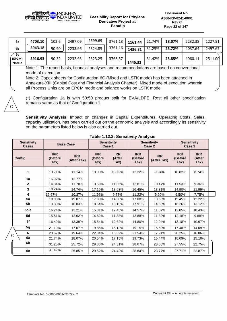
6a 4703.10 102.6 2497.09 2599.69 3761.13 1161.44 21.74% 18.07% 2232.38 1227.51
6b 3943.18 90.90 2233.96 2324.85 3761.16 1436.31 31.25% 25.72% 4037.64 2497.67
6c (EPCM) Note 2
3916.93 90.32 2232.93 2323.25 3768.57 1445.32
31.42% 25.85% 4060.11 2511.00
Note 1: The report basis, financial analyses and recommendations are based on conventional
mode of execution.
Note 2: Capex sheets for Configuration-6C (Mixed and LSTK mode) has been attached in
Annexure-XIII (Capital Cost and Financial Analysis Chapter). Mixed mode of execution wherein
all Process Units are on EPCM mode and balance works on LSTK mode.
(*) Configuration 1a is with 50:50 product split for EVA/LDPE. Rest all other specification remains same as that of Configuration 1 Sensitivity Analysis: Impact on changes in Capital Expenditures, Operating Costs, Sales, capacity utilization, has been carried out on the economic analysis and accordingly its sensitivity on the parameters listed below is also carried out.
Table 1.12.2: Sensitivity Analysis
Senstivity Cases
Base Case Sensitivity
Case 1 Sensitivity
Case 2 Sensitivity
Case 3
Config IRR
(Before Tax)
IRR (After Tax)
IRR (Before
Tax)
IRR (After Tax)
IRR (Before
Tax)
IRR (After Tax)
IRR (Before
Tax)
IRR (After Tax)
1 13.71% 11.14% 13.00% 10.52% 12.22% 9.94% 10.82% 8.74%
1a 16.92% 13.77%
2 14.34% 11.70% 13.58% 11.05% 12.81% 10.47% 11.53% 9.36%
3 18.24% 14.74% 17.19% 13.93% 16.45% 13.31% 14.90% 11.99%
4 12.67% 10.37% 11.95% 9.73% 11.22% 9.20% 9.50% 7.75%
5a 18.90% 15.07% 17.89% 14.30% 17.08% 13.63% 15.45% 12.22%
5b 19.80% 16.03% 18.64% 15.15% 17.91% 14.53% 16.26% 13.12%
5c/e 16.24% 13.21% 15.31% 12.45% 14.57% 11.87% 12.85% 10.43%
5d 15.51% 12.62% 14.62% 11.88% 13.88% 11.32% 12.18% 9.88%
5f 16.49% 13.39% 15.54% 12.62% 14.80% 12.04% 13.18% 10.67%
5g 21.10% 17.07% 19.86% 16.12% 19.15% 15.50% 17.48% 14.09%
6 23.67% 19.64% 22.34% 18.62% 21.54% 17.91% 20.25% 16.86%
6a 21.74% 18.07% 20.54% 17.15% 19.73% 16.44% 18.09% 15.10%
6b 31.25% 25.72% 29.36% 24.31% 28.67% 23.65% 27.55% 22.75%
6c 31.42% 25.85% 29.52% 24.42% 28.84% 23.77% 27.71% 22.87%
C
C

Feasibility Report for Ethylene
Derivative Project at Paradip
Document No.
A360-RP-0241-0001 Rev C
Page 23 of 147
Template No. 5-0000-0001-T2 Rev. C
Copyright EIL – All rights reserved
Table 1.12.3: Sensitivity Analysis
1.13 PROJECT FINANCING
The project financing is presently considered with 1:1 debt to equity ratio. The details of financing shall be detailed at DFR stage
1.14 PROJECT SCHEDULE
Zero date of the project is considered to be the date of investment approval completion by IOCL. The project schedule has been attached as Annexure XVI for Configuration-6C (EPCM). Following can be noted for the same-
Mechanical completion of the project is considered to be 37 months from the date of project management consultant selection.
Project management consultant is selected by IOCL one month after zero date.
Following to be noted regarding the project schedule of LSTK and Mixed mode implementation of Configuration-6C-
Mechanical completion of the project is considered to be 39.5 months from the date of project management consultant selection.
Project management consultant is selected by IOCL one month after zero date.
Job closure is considered to be 43.5 months from the date of project management consultant selection.
Senstivity Cases
Sensitivity Case 4
Sensitivity Case 5
Sensitivity Case 6
Sensitivity Case 7
Config IRR
(Before Tax) IRR
(After Tax) IRR
(Before Tax) IRR
(After Tax) IRR
(Before Tax) IRR
(After Tax) IRR
(Before Tax) IRR
(After Tax)
1 12.89% 10.46% 8.68% 7.01% 12.64% 10.25% 14.95% 12.16%
1a
2 13.60% 11.09% 9.41% 7.66% 12.92% 10.53% 14.29% 11.66%
3 17.26% 13.94% 12.32% 9.92% 15.96% 12.87% 17.39% 14.04%
4 11.55% 9.44% 7.09% 5.83% 10.95% 8.94% 12.48% 10.21%
5a 17.93% 14.27% 12.86% 10.14% 16.90% 13.41% 17.43% 13.86%
5b 18.75% 15.18% 13.53% 10.92% 17.12% 13.83% 18.63% 15.07%
5c/e 15.13% 12.30% 10.26% 8.32% 13.81% 11.22% 16.03% 13.04%
5d 14.42% 11.72% 9.64% 7.82% 13.27% 10.78% 15.00% 12.20%
5f 15.47% 12.55% 10.66% 8.63% 14.09% 11.42% 15.07% 12.23%
5g 20.06% 16.21% 14.69% 11.83% 18.83% 14.79% 19.30% 15.59%
6 22.79% 18.93% 17.45% 14.58% 18.96% 15.81% 22.52% 18.72%
6a 20.53% 17.09% 15.07% 12.65% 17.67% 14.76% 22.04% 18.32%
6b 30.52% 25.14% 24.46% 20.25% 25.44% 21.05% 28.92% 23.86%
6c 30.69% 25.26% 24.62% 20.36% 25.61% 21.17% 29.09% 23.98%
C
C

Feasibility Report for Ethylene
Derivative Project at Paradip
Document No.
A360-RP-0241-0001 Rev C
Page 24 of 147
Template No. 5-0000-0001-T2 Rev. C
Copyright EIL – All rights reserved
1.15 ENVIRONMENTAL CONSIDERATION The liquid, solid and gaseous effluent summary for all the configurations have been elaborated in Section 8 of this report.
For the liquid effluents, dedicated Effluent Treatment Plant has been provided in of the
ethylene derivative complex except for Configuration 6, 6A, 6B and 6C., for which IOCL confirmed that the Refinery ETP can accommodate the liquid effluents generated from these configuration.
For the gaseous effluent, Thermal Incinerator, RTO have been provided, wherever applicable.
Suitable destination for the solid waste has been described in Section 8 of the report.
1.16 RECOMMENDATION
With reference to the economic summary of all the configuration studied and tabulated in table 1.12.1 above; (i) Configuration 6C (EPCM) emerges to be the option with Highest IRR, highest NPV,
Lowest Total OPEX and minimum capex.
(ii) Configuration 4 emerges with the maximum Sales but with significantly low IRR , NPV vis a vis Configuration 6C (EPCM); this configuration also has the highest Total Opex and significantly high CAPEX as compared to Configuration 6C (EPCM)
(iii) The schedule will remain the same as informed above and the cash flows, CAPEX,
IRRs, Taxation etc can be reassessed at IOCL’s end based on their experience and choice of execution methodology.
With above as basis, Configuration 6C (EPCM) can be considered for pursuing further in detail feasibility report stage.
C
C

Feasibility Report for Ethylene
Derivative Project at Paradip
Document No.
A360-RP-0241-0001 Rev C
Page 25 of 147
Template No. 5-0000-0001-T2 Rev. C
Copyright EIL – All rights reserved
SECTION 2.0
INTRODUCTION
Feasibility Report for Ethylene
Derivative Project at Paradip
Document No.
A360-RP-0241-0001 Rev C
Page 26 of 147
Template No. 5-0000-0001-T2 Rev. C
Copyright EIL – All rights reserved
2.0 INTRODUCTION
The growth plan for Indian Oil Corporation Limited (IOCL), envisages operating the grass root refinery at Paradip with a crude processing capacity of 15 MMTPA. The refinery configuration has a high severity FCCU (INDMAX) unit with a capacity of 4.2 MMTPA which is presently under implementation. The off gas generated in the high severity mode contains a significant potential of ethylene which can be recovered for value addition. Potential exists to explore the possibilities of setting up of an Ethylene derivative complex to produce high value polymers / petrochemicals such as EVA/LDPE, EPDM, PVC, Styrene, MEG etc by considering feed stocks available from the grass root refinery such as FCC off gas, Oxygen and Propylene. Balance of the feed stock is considered as merchant purchase.
Indian Oil Corporation Limited has engaged the services of Engineers India Limited (EIL) to prepare Feasibility report (+/- 30 % Cost Estimate Accuracy) for the proposed ethylene derivative complex for IOCL to ascertain the technical aspects and take investment decision based on its viability. This report pertains to investment study covering briefly project configuration, project description, execution schedule, cost estimate, financial analysis, to enable IOCL in taking investment decision
It is proposed to utilize the feed streams available from the refinery as under.
2.1 FCC OFF GAS. 2.1.1 The off gas generated from FCC contains a significant potential of ethylene that can
be recovered for further value addition. Potential of ethylene is revised to 220 KTPA (from 230 KTPA defined in the Scope of Work) in the FR Design Basis document.
2.1.2 Ethylene is recovered from the FCC off gas in a Ethylene Recovery Unit (ERU), licensed / designed by ABB Lummus. The ABB Lummus package of ERU is designed for 180 KTPA of 99.5 wt % Ethylene.
2.1.3 For the proposed Ethylene Derivative complex, 220 KTPA of Polymer grade Ethylene (99.9 mole % ethylene content) to be made available.
2.1.4 The ERU design needs to be revisited to make it suitable for generating 220 KTPA of Polymer grade ethylene. However, directional requirements in design corresponding to augmentation have been considered in the FR. List of additional hardware, as suggested by Licensor, for generating 180 KTPA of Polymer grade ethylene is attached as Annexure XIX.
2.1.5 For the purpose of the FR, it is considered that ERU will produce 220 KTPA of Polymer grade Ethylene.
2.1.6 Ethylene from the upstream ERU will be used as feed to the downstream units of the Ethylene Derivative Complex.
2.1.7 Ethylene Recovery Unit (ERU) is considered as a part of the ethylene derivative complex and is included in project cost estimate.
2.1.8 ERU is designed by M/S Lummus (CB&I) to process FCC off gas after DEA wash (Absorber within INDMAX unit , regenerator in Paradip Refinery). IOCL has replaced Off gas Amine Scrubber solvent from DEA to MDEA. Hence another standalone Absorber-Regenerator system with DEA as solvent, to be installed upstream of ERU within Ethylene Derivative Complex.
C

Feasibility Report for Ethylene
Derivative Project at Paradip
Document No.
A360-RP-0241-0001 Rev C
Page 27 of 147
Template No. 5-0000-0001-T2 Rev. C
Copyright EIL – All rights reserved
2.2 PROPYLENE.
2.2.1 Propylene required for the downstream unit, as the case may be, will come from the
upstream Propylene Recovery Unit (PRU) of the refinery, this PRU is excluded from the scope of FR. Propylene purity available from this PRU is 93 wt%.
2.2.2 The purity of this Propylene is further enhanced to 99.5 wt% in another PRU, which has been envisaged as part of the C2 derivative complex.
With the above feed stock available from the refinery and balance feed stock considered as merchant purchase, several configuration were explored for the Proposed Ethylene Derivative complex. The details of the various configuration along with the unit capacities, material balance, utility balance, product slate are covered in Section 7, Project Description, of the Feasibility report.

Feasibility Report for Ethylene
Derivative Project at Paradip
Document No.
A360-RP-0241-0001 Rev C
Page 28 of 147
Template No. 5-0000-0001-T2 Rev. C
Copyright EIL – All rights reserved
SECTION 3.0
SCOPE

Feasibility Report for Ethylene
Derivative Project at Paradip
Document No.
A360-RP-0241-0001 Rev C
Page 29 of 147
Template No. 5-0000-0001-T2 Rev. C
Copyright EIL – All rights reserved
3.0 SCOPE
Scope of job is as per the Job Contract – “Contract for Consultancy Services for Preparation of Feasibility Report (FR) for Ethylene Derivative Project at Paradip. Dated 25th September 2012.” The Contract document is not a part of this report. Contract document is to be referred separately.

Feasibility Report for Ethylene
Derivative Project at Paradip
Document No.
A360-RP-0241-0001 Rev C
Page 30 of 147
Template No. 5-0000-0001-T2 Rev. C
Copyright EIL – All rights reserved
SECTION 4.0
DESIGN BASIS

Feasibility Report for Ethylene
Derivative Project at Paradip
Document No.
A360-RP-0241-0001 Rev C
Page 31 of 147
Template No. 5-0000-0001-T2 Rev. C
Copyright EIL – All rights reserved
4.0 DESIGN BASIS
Signed Design Basis of the FR (Document no: A360-PET1-0001, Rev D) is enclosed as Annexure-I. Design Basis was signed during the Meeting of the project during 30th October 2012 held at IOCL’ office, Yusuf Sarai, New Delhi. However during the course of the project, certain points of the basis were updated based on the discussion and agreement between IOCL/EIL. Updation /modification of signed design basis is noted below. These points supersede the data/information provided in signed design basis.
Updation / modification to Signed Design basis. 4.1 IOCL informed that green belt is not to be considered for the Ethylene derivative
complex plot area estimation as required green belt has already been provided (refer Paradip Refinery Project Overall Site Plan, Drawing no: PDRP4200-8230-01-600-0001 Sh 1 of 1, Rev S1) within the present refinery plot plan. Thus, (IOCL vide email dated 5th April 2013) both pink highlight lateral hatched area and green highlight cross hatched area are available as plant area for the C2 derivative complex.
4.2 IOCL informed, for Capex estimation, Land cost to be considered is NIL, However, suitable site development charge, based on the plot area estimated, is to be included in the Capex of the C2 derivative complex.
4.3 The utility requirement for all the configuration of the proposed ethylene derivative complex assuming 100% captive generation was prepared and discussed with IOCL. IOCL reviewed and informed that Ethylene Derivative complex will only receive HSFO and Treated Raw Water (TRW) from the Refinery for all the configurations. Additionally Ethylene derivative complex will also receive the following streams from Refinery: a) IA, PA and N2 for Configuration 6 b) IA, PA, N2 and DM water for Configuration 6A and c) IA, PA, N2, DM, BFW, Steam and Power for Configuration 6B and 6C. RLNG is used as a fuel for Ethylene Derivative complex considering potential availability of natural gas at Paradip by the time Ethylene Derivative Complex is implemented. For the purpose of this FR, RLNG is considered to be made available at the C2 derivative complex battery limit by IOCL.Hence, all the utility block, except for Raw water treatment plant ,have been considered as 100% Captive generation within the Ethylene derivative complex, unless otherwise mentioned.
4.4 As informed by IOCL, C2 derivative complex and PP complex will share a single flare system which shall be located within PP complex. Augmentation of PP flare system will be carried out by IOCL to make it suitable for C2 derivative complex flare load as well. Hence, no plot or hardware have been allocated for the flare system of C2 derivative complex. However, cost of Flare system for Ethylene Derivative Complex have been developed for differential flare load (that is, differential of PP + C2 derivative flare load and only PP flare load) which would then be passed between Projects internally by IOCL.
4.5 Dedicated fire training ground has not been considered for the C2 derivative complex. It is assumed that the fire training ground of the existing Paradip complex will be shared by C2 derivative complex.
4.6 As required by IOCL, prices for EB and VCM (these being intermediate product) have not been considered in the Working capital margin calculation.
4.7 IOCL informed, post operation of refinery FCC in Petrochemical mode and subsequent to implementation of Polypropylene Unit, FCC off gas generated is to be completely consumed as fuel gas in the refinery (with a major quantity being routed to Utility
C
Feasibility Report for Ethylene
Derivative Project at Paradip
Document No.
A360-RP-0241-0001 Rev C
Page 32 of 147
Template No. 5-0000-0001-T2 Rev. C
Copyright EIL – All rights reserved
Boilers ) . Therefore, when FCC off gas is utilized as feed to ethylene derivative complex instead of being consumed as fuel gas in the refinery, refinery would be required to use incremental liquid fuel. IOCL informed that this incremental liquid fuel required by Refinery, is to be considered as HSFO
4.8 With the above philosophy, EIL worked out the material balance and assessed the quantity of incremental liquid fuel , required by Refinery, after accounting for the by product streams from ERU Unit sent back to refinery as fuel gas.
4.9 The cost of incremental liquid fuel (net of revenue realized in refinery off gas sales to ethylene derivatives unit) required for Paradip refinery, as determined above, have been included in the economics of Ethylene Derivative Complex.
4.10 IOCL informed, Oxygen required for PVC or MEG unit will be supplied to the C2 derivative complex over the fence, hence ASU has been removed from C2 derivative complex. To meet the Nitrogen demand of the complex, Cryogenic Nitrogen plant has been provided in the complex.
4.11 IOCL informed the following Fuel type to be used in the Ethylene Derivative complex. 4.11.1 RLNG to be used for Process unit heaters 4.11.2 High Sulfur Fuel oil (HSFO) to be used for Utility Boilers 4.11.3 RLNG to be used as the fuel for GT-HRSG 4.11.4 Fuel gas generated from ERU is to be used as fuel for flare purging in the C2
derivative complex. Balance fuel gas will be routed back to the refinery complex.
4.12 IOCL informed that presently the SOX emission from refinery almost completely utilizes the limit allowed by Pollution control Norms .Thus negligible margin is available for the Ethylene derivative complex.
4.13 In view of above and due to high sulfur content in the HSFO (Maximum Sulfur content=4.9 wt%), Flue Gas Desulphurization is considered for the Ethylene derivative complex. Existing refinery is implementing amine based FGD, accordingly the same technology was used as basis for FR purpose.
4.14 Flue gas absorber shall be installed in Ethylene Derivative Complex and Amine regenerator of Refinery CPP FGD shall be used for Ethylene derivative FGD as well. Rich amine from C2 derivative complex shall be sent back to refinery CPP FGD regenerator. Lean Amine to Ethylene Derivative complex shall be supplied from the refinery CPP FGD regenerator. IOCL informed that Refinery facilities like FGD regenerator, Sulphur Block etc. are adequate to cater to the load contributed from the C2 Derivative complex.
4.15 As IOCL informed that the stand by Boiler and GT-HRSG of the Refinery is to be used as a common spare for both the Refinery and Ethylene derivative complex, No sparing has been considered for UB, GT-HRSG and STG in the Ethylene derivative complex. This philosophy has been followed for all the configuration of the C2 derivative complex.
4.16 Dedicated Effluent Treatment Plant has been considered for the C2 derivative complex except for Configuration 6, 6A, 6B and 6C for which IOCL confirmed that the Refinery ETP can accommodate the extra load contributed by C2 derivative complex. Hence no new ETP has been considered for Configuration 6, 6A, 6B and 6C.
4.17 As required by IOCL, for Configuration 5b, c, d and 5e, excess ethylene is to be sold as merchant sale. Ethylene tankers being refrigerated type, refrigerated offsite storage has been provided for Product ethylene for the above cases.
4.18 As informed by IOCL, the following points have been duly incorporated in the capex estimation and financial analysis for all the configuration of the C2 derivative complex FR.
4.18.1 Contingency in CAPEX estimation is considered as 5%
C

Feasibility Report for Ethylene
Derivative Project at Paradip
Document No.
A360-RP-0241-0001 Rev C
Page 33 of 147
Template No. 5-0000-0001-T2 Rev. C
Copyright EIL – All rights reserved
4.18.2 CENVAT credit has been considered 4.18.3 Long term interest rate has been considered as 12.0 % 4.18.4 10% payment spill over has been considered in the first year of operation. 4.18.5 Capital phasing percentage to be as follows: 10,35,45,10 for Year 1,2,3,4
respectively. 4.18.6 Debt : Equity = 1:1 4.18.7 Expenditure Pattern: Debt Equity concurrent. 4.18.8 Construction site requirement has been considered @ 0.2% of the project cost
excluding margin money & financing cost 4.18.9 Construction Period expenses has been considered @ 0.5% of the project cost
excluding margin money & financing cost 4.18.10 First charge of fixed bed catalysts & 3 months consumption of
additives/chemicals/makeup catalyst has been capitalized 4.18.11 Lumpsum provision of Rs 15 Crore has been considered for Lab
equipment. 4.18.12 Intermediate product storage has been considered for 5 days instead of 8
days considered in the draft FR
4.19 Working Capital Margin has been calculated considering the following inventory 4.19.1 Internal stream = 3 days 4.19.2 Imported Feed = 15 days 4.19.3 Warehouse solid = 15 days 4.19.4 Liquid product = 7 days
4.20 However, for Capex estimation, storage philosophy considered for designing the offsite tanks /warehouse used for storing raw material / intermediate product / Product will be as per the signed Design basis (Doc no : A360-PET1-0001 , Rev D), except for intermediate product storage for which storage days has been considered as 5 days instead of 8 days considered in the Design Basis.
4.21 As informed by IOCL, the following facilities have not been considered as part of the C2 derivative complex.
4.21.1 Fire training ground 4.21.2 Fire protection system that is Fire water tank, Fire water pump house. 4.21.3 Workshop 4.21.4 Maintenance shop and warehouse 4.21.5 Central store 4.21.6 Product development 4.21.7 Technology building 4.21.8 Project office Facilities, as tabulated above, have been considered common for both refinery and C2 derivative complex, and same will be build within the Refinery complex. Hence, space and cost provision for the above facilities has not been kept in the c2 derivative complex..
4.22 Only Lab and Control room have been considered as new facility within C2 derivative complex.
4.23 As informed by IOCL, Instrument air, Plant air and Nitrogen required for Configuration 6, 6A, 6B and 6C will be supplied from the Refinery Compressed air plant and Nitrogen Plant. Thus, no new facility generating compressed air and nitrogen have been envisaged as part of the C2 derivative complex for these three configurations
4.24 DM water required for Configuration 6A, 6B and 6C will be supplied from the Refinery DM water plant. Hence, DM plant have not been considered in the C2 derivative
C

Feasibility Report for Ethylene
Derivative Project at Paradip
Document No.
A360-RP-0241-0001 Rev C
Page 34 of 147
Template No. 5-0000-0001-T2 Rev. C
Copyright EIL – All rights reserved
complex for these three configuration 4.25 The drive type of Binary Refrigerant Compressor of ERU in ABB Lummus BDEP is
VHP-MP type. Drive type has been selected between VHP-MP and VHP-Condensing in the ERU for individual configuration based on the usage of steam at various levels and accordingly optimized the boiler configuration and fuel consumption.
4.26 Complete Steam, Power, DM Water, BFW, Compressed Air and Nitrogen will be met from refinery facility. Hence, Configuration- 6C will only have dedicated CW System and CPU in C2 derivative complex.
4.27 Recycle Compressor of MEG Unit is considered to be driven by steam (VHP to HP/Condensing). LP Steam, as required by the complex shall be generated by letting down HP Steam via PRDS located in MEG Unit.
4.28 Configuration-4A, 4B is standalone styrene project comprising of ERU, EB/SM as
designed by CB&I Lummus. Configuration-4A will have its independent Utility & Offsite facilities ,as was the basis adopted in Configurations 1,1A ,2,3,4, 5 A-G and 6. Configuration-4B will have integration with Paradip refinery w.r.t. Utilities comprising of HSFO, Treated Raw Water, DM, BFW, IA, PA, N2, VHP Steam and Power completely sourced from the refinery. Refer Annexure-XX wherein required comparison of 4A, 4B vis a vis Configuration- 6C has been done.
4.29 FEED PRODUCT UTILITY PRICE
The following prices of Feed, Product and utility streams have been provided by IOCL vide email dated 28/29/30th May 2013 and on 26th June 2013. All prices are expressed in INR/Ton Feedstock prices are “delivered prices at refinery gate” and product prices are “IOCL Net
back prices”. Table 4.26.1: Product Prices
Import Parity price Export Parity price
Product Basis of Origin 3yrs Avg 5 yrs Avg 7 yrs Avg.
3yrs Avg 5 yrs Avg 7 yrs Avg.
LDPE CFR SE Asia (Platts) 85,707 83,279 84,465 75,205 72,962 74,058
PVC CFR SE Asia(Platts) 60,267 57,565 57,316 51,451 48,956 48,726
Styrene CFR India (Platts) 79,370 72,070 73,066 73,496 66,518 67,470
EVA (14-20%) CFR CMP (ICIS) 119804 112121 109323 108043 100877 98,268
Toluene CFR India (Platts) 64,833 57,491 57,616
Ethylene CFR SE Asia 66,616 48,488 50,424
EPDM CFR China (IIPMR) & ICIS
188448 166979 160082 172804 152781 146348
Caustic lye CFR SE Asia 24,923 23,160 22,170
Hydrogen 179,615 158,851 153,626
LPG 45,319 39,817 36,726
MEG IOCL data provided on 26.6.2013 59,132 51,963 53,962
DEG IOCL data provided on 26.6.2013 61,604 54,747 55,849
TEG IOCL data provided 86,936 86,936 86,936
C

Feasibility Report for Ethylene
Derivative Project at Paradip
Document No.
A360-RP-0241-0001 Rev C
Page 35 of 147
Template No. 5-0000-0001-T2 Rev. C
Copyright EIL – All rights reserved
on 26.6.2013
Table 4.26.2: Feed Prices
Feed Basis of Origin 3yrs Avg 5 yrs Avg 7 yrs Avg.
FCC Off gas FO RTP adjusted for calorific value 39669 (*) 34436 (*) 30669 (*)
Benzene FOB Korea 66,757 59,437 60,062
ENB 3.5 times butadiene NW Europe contract price
4,14,260 3,38,380 3,18,290
EDC CFR SE Asia (Platts) 22,118 22,188 22,755
VAM CFR SE Asia (Platts) 61,873 59,883 62,826
Salt NE Asia delivered (Contract) 3,585 3,461 3,161
Oxygen IOCL data provided on 13.6.2013 2,472 2,472 2,472
Propylene LPG RTP plus PRU Opex 47844 42342 39251
Table 4.26.3: Utility Prices
Utility Basis 3yrs Avg 5 yrs Avg 7 yrs Avg.
RLNG IOCL data provided on 13.06.2013 (LHV=10500 kcal/kg)
21,609 21,609 21,609
Treated raw water
Clause 4.4 of PDRP-8820-SP-0001_Rev_F2
35.1 35.1 35.1
HSFO N.E/Haldia RTP 33,905 (*) 29,432 (*) 26,213 (*)
Naphtha EPP Barauni 44,985 39,521 38,147
RFO/IFO HSD BS III N.E/Haldia RTP 47,632 42,054 39,282
(*) Refer final prices from Table: 4.27.2.2
However, during the course of the project, few price basis were updated. Updation /modification to the above price basis is noted below. These points supersede the data/information provided in the price table above.
4.27.1 Propylene price as provided by IOCL corresponds to 93 wt% Propylene. FCC off gas
price as provided by IOCL corresponds to the off gas upstream of the DEA scrubber of FCC..
4.27.2 Following was informed by IOCL: (i) The price of HSFO, which will be used as fuel for C2 derivative complex and as
incremental fuel for Paradip refinery, is to be considered as 90% of the FO Refinery Transfer Price. The FO RTP (INR = 33905 / MT, 3 years average) has been provided by IOCL to EIL vide email dated 27th May 2013 Thus HSFO price to be adopted is INR 30514.5/ MT (3 year average).
(ii) The HSFO price, which is 90% of the FO RTP, is to be considered as the benchmark price for the C2 derivative complex and FCC off gas, C2 purge and Fuel gas, from C2 complex to refinery, have been priced based on the HSFO price with LHV correction.
(iii) Oxygen will be supplied to the C2 derivative complex over the fence, hence ASU has been removed. To meet the Nitrogen demand of the complex, Cryogenic Nitrogen plant has been provided in the complex.
(iv) Price of EDC , which will be used as feed for Configuration 5a,b,c,d,e,f,g of C2 derivative complex, is to be considered as 90% of the EDC price provided by

Feasibility Report for Ethylene
Derivative Project at Paradip
Document No.
A360-RP-0241-0001 Rev C
Page 36 of 147
Template No. 5-0000-0001-T2 Rev. C
Copyright EIL – All rights reserved
IOCL to EIL vide email dated 29th May 2013 ( INR 22118 / MT, 3 year average) Thus EDC price to be adopted is INR 19906.2 / MT, 3 year average .
(v) Price of C3 product to be calculated as follows: Propylene content in the stream priced at propylene price, Balance components of the stream priced at LPG price
(vi) BT byproduct to be priced as follows: The weighted average price of Benzene and toluene in the ratio they are present in the stream
With the above modification in the price basis, the revised feed, product, utility prices are provided in the table below:
Table 4.27.2.1: Revised Feed, Product, Utility Prices
Stream 3yrs Avg. 5 yrs Avg. 7 yrs Avg.
EDC 19,906 19,969 20,479.5
C3 Product 47202 41700 38609
BT Byproduct 64113 56923 57191
Considering HSFO price as the benchmark, FCC off gas, Fuel gas, Compressed off gas and C2 purge stream have been priced based on HSFO price with corrected LHV.
Table 4.27.2.2: Revised Feed, Product, Utility Prices
Stream LHV Calculated (Kcal/kg)
3yrs Avg. 5 yrs Avg. 7 yrs Avg.
HSFO 9624 30514.5 26488.8 23591.7
FCC Off Gas 9551 30283 26287.9 23412.8
Fuel Gas to OSBL 8773 27816.3 24146.5 21505.6
C2 Purge 11300 35828.5 31101.8 27700.1
Compressed Off Gas 17100 54218.4 47065.5 41917.9
4.27.3 Post submission of Draft FR report, updated price sets for Feed, Products and Utilities
considering USD/INR conversion of 61.65 (one month average) were provided by IOCL vide Email dated 30th /31st October 2013 and on 27th November 2013.
All prices are expressed in INR/Ton Feedstock prices are “delivered prices at refinery gate” and product prices are “IOCL Net
back prices”.
Table 4.27.3.1: Updated Product Prices
Import Parity price Export Parity price
Product Basis of Origin 3yrs Avg 5 yrs Avg 7 yrs Avg 3yrs Avg 5 yrs Avg 7 yrs Avg
LDPE CFR SE Asia (Platts) 99,456 93,447 96,711 87,542 81,994 85,008
PVC CFR SE Asia(Platts) 68,739 64,356 65,250 58,916 54,869 55,695
Styrene CFR India (Platts) 96,400 83,963 85,526 88,310 76,542 78,021
EVA (14-20%) CFR CMP (ICIS) 1,35,077 1,24,877 1,25,707 1,20,660 1,11,243 1,12,009
EVA (22-30%) CFR Asia SW (ICIS) 1,45,877 1,34,588 1,34,588 1,30,655 1,20,231 1,20,231
Benzene FOB Korea 78,975 67,497 68,590

Feasibility Report for Ethylene
Derivative Project at Paradip
Document No.
A360-RP-0241-0001 Rev C
Page 37 of 147
Template No. 5-0000-0001-T2 Rev. C
Copyright EIL – All rights reserved
Toluene CFR India (Platts) 76,268 65,298 65,725
LPG N.E/Haldia RTP 54365 40839 38287 Ethylene CFR SE Asia 76,969 68,910 71,441 62,506 54,843 57,249
EPDM CFR China (IIPMR) & ICIS 2,10,712 1,88,086 1,81,022 1,91,229 1,70,338 1,63,815
Caustic lye CFR SE Asia 28,963 25,374 25,247
MEG CFR CMP (ICIS) 69,395 59,359 61,710 62,017 52,521 54,746
DEG CFR CMP (ICIS) 69,983 62,496 64,174 62,573 55,489 57,077
TEG FOB Indian Port 1,12,300 1,12,300 1,12,300 1,12,300 1,12,300 1,12,300
Table 4.27.3.2: Updated Feed Prices
Feed Basis of Origin 3yrs Avg 5 yrs Avg 7 yrs Avg.
ENB 3.5 times Butadiene NW Europe contract price 4,82,074 4,00,135 3,65,224
93 wt% Propylene LPG RTP plus PRU Opex 55890 43364 40812
EDC CFR SE Asia (Platts) 24,207 24,415 25,549
VAM CFR SE Asia (Platts) 71,153 65,969 71,022
Salt NE Asia delivered (Contract) 4,042 3,936 3,611
Benzene FOB Korea 78,975 67,497 68,590
Oxygen IOCL data provided on 13.6.2013 2,472 2,472 2,472
Table 4.27.3.3: Updated Utility Prices
Utility Basis 3yrs Avg 5 yrs Avg 7 yrs Avg.
RLNG IOCL data provided on 13.06.2013 (LHV=10500 kcal/kg)
24,660 24,660 24,660
Naphtha FOB AG 55,012 46,788 46,529
IFO HSD BS III 50,345 43,939 41,021
Fuel Oil FO Non-Fert RTP for N.E./haldia 35743 30962 27672
HSFO 90% of FO RTP 32168.7 27865.8 24904.8
Treated raw water
Clause 4.4 of PDRP-8820-SP-0001_Rev_F2
40.07 40.07 40.07
DM water Clause 4.4 of PDRP-8820-SP-0001_Rev_F2
67.82 67.82 67.82
Boiler Feed water
Price considered same as DM water 67.82 67.82 67.82
VHP steam IOCL data provided on 27th November 2013
1732.9 1732.9 1732.9
Power IOCL data provided on 27th November 2013
8 Rs/KWh 8 Rs/KWh 8 Rs/KWh
Instrument air
Clause 4.4 of PDRP-8820-SP-0001_Rev_F2
616.5 616.5 616.5
Plant air As informed by IOCL, Plant air price is considered same as IA price
616.5 616.5 616.5
Nitrogen IOCL data provided on 28th November 2013
5200 5200 5200

Feasibility Report for Ethylene
Derivative Project at Paradip
Document No.
A360-RP-0241-0001 Rev C
Page 38 of 147
Template No. 5-0000-0001-T2 Rev. C
Copyright EIL – All rights reserved
In line with Clause 4.24.2.v and vi) above the C3 product and BT byproduct prices have been worked out and same is tabulated below:
Product Basis of Origin 3yrs Avg 5 yrs Avg 7 yrs Avg.
C3 product
Propylene content in the stream priced at propylene price, Balance components of the stream priced at LPG price 55,539 42,783 40,231
BT byproduct
The weighted average price of Benzene and toluene in the ratio they are present in the stream 75,550 64,649 65,262
In line with Clause 4.24.2.i) the HSFO price, which is 90% of the FO RTP, is considered as
the benchmark price for the C2 derivative complex and FCC off gas, C2 purge and Fuel gas, from C2 complex to refinery, have been priced based on the HSFO price with LHV correction, and same is tabulated below.
Stream LHV Calculated (Kcal/kg)
3yrs Avg. 5 yrs Avg. 7 yrs Avg.
HSFO 9624 32168.7 27865.8 24904.8
FCC Off Gas 9704 32436.1 28097.4 25111.8
Fuel Gas to OSBL 8773 29324.2 25401.8 22702.6
C2 Purge 11300 37770.8 32718.6 29241.9
Compressed Off Gas 17100 57157.6 49512.2 44251.0

Feasibility Report for Ethylene
Derivative Project at Paradip
Document No.
A360-RP-0241-0001 Rev C
Page 39 of 147
Template No. 5-0000-0001-T2 Rev. C
Copyright EIL – All rights reserved
SECTION 5.0
MARKET SURVEY

Feasibility Report for Ethylene
Derivative Project at Paradip
Document No.
A360-RP-0241-0001 Rev C
Page 40 of 147
Template No. 5-0000-0001-T2 Rev. C
Copyright EIL – All rights reserved
5.0 MARKET SURVEY
The market survey study for the proposed Ethylene derivative complex is out side the scope of the Feasibility Report and thus same is not included in this Feasibility Report. IOCL has separately conducted the Market Survey study for the products from the proposed Ethylene Derivative Complex by Industrial Development Services (IDS)
Feasibility Report for Ethylene
Derivative Project at Paradip
Document No.
A360-RP-0241-0001 Rev C
Page 41 of 147
Template No. 5-0000-0001-T2 Rev. C
Copyright EIL – All rights reserved
SECTION 6.0
PROJECT LOCATION

Feasibility Report for Ethylene
Derivative Project at Paradip
Document No.
A360-RP-0241-0001 Rev C
Page 42 of 147
Template No. 5-0000-0001-T2 Rev. C
Copyright EIL – All rights reserved
6.0 PROJECT LOCATION
The project is to be located as part of the existing refinery complex of IOCL at Town/City: Abhaychandrapur, Paradip, Distt: Jagatsinghpur, Orissa. The site is located at Latitude 20° 15’ 20” and Longitude 86° 36’ 00”. The site is at minimum 3.91 m above Indian mean sea level (IMSL) which corresponds to the site recorded flood level The site for new facilities coming in Ethylene Derivative complex shall be located within the boundary wall of the existing refinery facilities at Paradip, Orissa. Since the proposed FR for Ethylene derivative complex at Paradip is being considered as part of the existing refinery complex, available area within the complex boundary, as earmarked by IOCL, has been considered for the expansion.
6.1 PLOT PLAN CONSIDERATION 6.1.1 IOCL informed that additional green belt is not to be considered for the Ethylene
derivative complex plot area estimation ; since required green belt has already been provided (refer Paradip Refinery Project Overall Site Plan, Drawing no: PDRP4200-8230-01-600-0001 Sh 1 of 1, Rev S1) within the present refinery plot plan.
6.1.2 Since Ethylene derivative complex will receive TRW from refinery, hence, no raw water reservoir / RWTP / treated raw water reservoir are considered in the plot. However, treated raw water pump, pumping Treated raw water from refinery to Ethylene derivative complex are considered for the Ethylene derivative complex.
6.1.3 C2 derivative complex and PP complex will share a single flare system which shall be located within PP complex. Hence, no plot space has been considered for flare system within C2 derivative complex.
6.1.4 As informed by IOCL, the following facilities have not been considered as part of the C2 derivative complex.
Fire training ground
Fire protection system that is Fire water tank, Fire water pump house.
Workshop
Maintenance shop and warehouse
Central store
Product development
Technology building
Project office Facilities, as tabulated above, have been considered common for both refinery and C2 derivative complex, and same will be build within the Refinery complex. Hence, cost provision or plot provision for the above facilities has not been kept in the C2 derivative complex. Only Lab and Control room have been considered as new facility within C2 derivative complex
6.1.5 IOCL informed that the effluent generated in Configuration 6, 6A, 6B and 6C can be treated in the Refinery ETP, hence dedicated Effluent Treatment Plant have not been envisaged in the Ethylene derivative complex for these four configurations.
6.1.6 Also as informed by IOCL, Instrument air, Plant air and Nitrogen required for Configuration 6, 6A, 6B and 6C will be supplied from the Refinery Compressed air plant and Nitrogen Plant. Thus, no new facility generating compressed air and nitrogen have been envisaged as part of the C2 derivative complex for these four configurations.
C

Feasibility Report for Ethylene
Derivative Project at Paradip
Document No.
A360-RP-0241-0001 Rev C
Page 43 of 147
Template No. 5-0000-0001-T2 Rev. C
Copyright EIL – All rights reserved
6.1.7 DM water required for Configuration 6A, 6B and 6C will be supplied from the Refinery DM water plant. Hence, DM plant has not been considered in the C2 derivative complex for these three configurations.
With the above consideration, the plot area (excluding green belt) for all the configuration of the C2 derivative complex have been estimated out and is presented in the table below.
Table: 6.1.1: Estimated Plot Area
Configuration Estimated Plot Area in Hectares
Conf-1 48.8
Conf-2 74.1
Conf-3 63.8
Conf-4 86.3
Conf-5a 115.3
Conf -5b 77.4
Conf -5c 67.8
Conf -5d 65.8
Conf -5e 77.4
Case-5f 64.5
Case-5g 69.58
Case-6 48
Case-6A 46
Case-6B 33
Case-6C 31
Plot Plan Drawing for Configuration 6C is attached as Annexure XV
C
C

Feasibility Report for Ethylene
Derivative Project at Paradip
Document No.
A360-RP-0241-0001 Rev C
Page 44 of 147
Template No. 5-0000-0001-T2 Rev. C
Copyright EIL – All rights reserved
SECTION 7.0
PROJECT DESCRIPTION
Feasibility Report for Ethylene
Derivative Project at Paradip
Document No.
A360-RP-0241-0001 Rev C
Page 45 of 147
Template No. 5-0000-0001-T2 Rev. C
Copyright EIL – All rights reserved
7.0 PROJECT DESCRIPTION The growth plan for Indian Oil Corporation Limited (IOCL), envisages operating the grass root refinery at Paradip with a crude processing capacity of 15 MMTPA. The refinery configuration has a high severity FCCU (INDMAX) unit with a capacity of 4.2 MMTPA which is presently under implementation. The off gas generated in the high severity mode contains a significant potential of ethylene which can be recovered for value addition. Potential exists to explore the possibilities of setting up of an Ethylene derivative complex to produce high value polymers / petrochemicals such as EVA/LDPE, EPDM, PVC, Styrene, MEG etc by considering feed stocks available from the grass root refinery such as FCC off gas, Oxygen and Propylene. Balance of the feed stock is considered as merchant purchase.
Indian Oil Corporation Limited has engaged the services of Engineers India Limited (EIL) to prepare Feasibility report (+/- 30 % Cost Estimate Accuracy) for the proposed ethylene derivative complex for IOCL to ascertain the technical aspects and take investment decision based on its viability. This report pertains to investment study covering briefly project configuration, project description, execution schedule, cost estimate, financial analysis, to enable IOCL in taking investment decision
It is proposed to utilize the FCC off gas and Propylene feed streams available from the refinery.
With the above feed stock available from the refinery and considering the balance feed stock available as merchant purchase, several configurations were explored for the Proposed Ethylene Derivative complex. The details of the various configurations along with the unit capacities, material balance, utility balance, product slate are covered in the next section, of the Feasibility report.

Feasibility Report for Ethylene
Derivative Project at Paradip
Document No.
A360-RP-0241-0001 Rev C
Page 46 of 147
Template No. 5-0000-0001-T2 Rev. C
Copyright EIL – All rights reserved
SECTION 7.1
PROJECT CONFIGURATION

Feasibility Report for Ethylene
Derivative Project at Paradip
Document No.
A360-RP-0241-0001 Rev C
Page 47 of 147
Template No. 5-0000-0001-T2 Rev. C
Copyright EIL – All rights reserved
7.1.1 FEED SPECIFICATION
The following methodologies were adopted for fixing the feed definition for the proposed Ethylene derivative complex.
7.1.1.1 The off gas generated from FCC contains a significant potential of ethylene that can be recovered for further value addition. Potential of ethylene is revised to 220 KTPA (from 230 KTPA defined in the Scope of Work) in the FR Design Basis document.
7.1.1.2 Ethylene is recovered from the FCC off gas in a Ethylene Recovery Unit (ERU), licensed / designed by ABB Lummus. The ABB Lummus package of ERU is designed for 180 KTPA of 99.5 wt % Ethylene.
7.1.1.3 For the proposed Ethylene Derivative complex, 220 KTPA of Polymer grade Ethylene (99.9 mole % ethylene content) is to be made available.
7.1.1.4 ERU design needs to be revisited to make it suitable for generating 220 KTPA of Polymer grade ethylene. However, directional requirements in design corresponding to augmentation have been considered in the FR. List of additional hardware, as suggested by Licensor, for generating 180 KTPA of Polymer grade ethylene is attached as Annexure XIX.
7.1.1.5 For the purpose of the FR, it is considered that ERU will produce 220 KTPA of Polymer grade Ethylene.
7.1.1.6 Ethylene from the upstream ERU will be used as feed to the downstream units of the Ethylene Derivative Complex.
7.1.1.7 Ethylene Recovery Unit (ERU) is considered as a part of the ethylene derivative complex and is included in project cost estimate.
7.1.1.8 ERU is designed by M/S Lummus (CB&I) to process FCC off gas after DEA wash (Absorber within INDMAX unit, regenerator in Paradip Refinery). IOCL has replaced Off gas Amine Scrubber solvent from DEA to MDEA. Hence another stand alone Absorber-Regenerator system with DEA as solvent, to be installed upstream of ERU within Ethylene Derivative Complex.
7.1.1.9 Propylene required for the downstream unit, as the case may be, will come from the upstream Propylene Recovery Unit (PRU) of the refinery, this PRU is excluded from the scope of FR. Propylene purity available from this PRU is 93 wt%.
7.1.1.10 The purity of this Propylene is further enhanced to 99.5 wt% in another PRU, which has been envisaged as part of the C2 derivative complex.
7.1.2 FEED STOCK AVAILABILITY AND CHARACTERISTICS:
The following are the major potential feed stocks for the various configuration of the Ethylene derivative complex.
a) Ethylene
Ethylene generated from ERU shall be stored in Horton sphere, unless otherwise mentioned, and will be used as feed for the downstream unit. For Configuration 5b, 5c and 5d excess of the Ethylene, after meeting the unit requirement, shall be sold as merchant sale. Product ethylene for merchant sale will be stored in Refrigerated storage. Offsite storage facility for Ethylene is considered as part of the C2 complex. Ethylene will be used as feed stock for EVA/LDPE unit, EPDM unit, EDC/VCM unit, EB unit and MEG unit, that is in all of the Configuration of the Ethylene derivative complex.
C
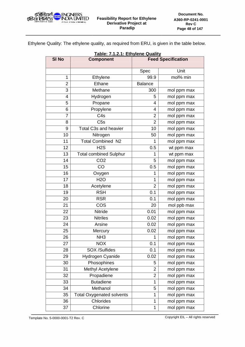
Feasibility Report for Ethylene
Derivative Project at Paradip
Document No.
A360-RP-0241-0001 Rev C
Page 48 of 147
Template No. 5-0000-0001-T2 Rev. C
Copyright EIL – All rights reserved
Ethylene Quality: The ethylene quality, as required from ERU, is given in the table below.
Table: 7.1.2.1: Ethylene Quality
Sl No Component Feed Specification
Spec Unit
1 Ethylene 99.9 mol% min
2 Ethane Balance
3 Methane 300 mol ppm max
4 Hydrogen 5 mol ppm max
5 Propane 4 mol ppm max
6 Propylene 4 mol ppm max
7 C4s 2 mol ppm max
8 C5s 2 mol ppm max
9 Total C3s and heavier 10 mol ppm max
10 Nitrogen 50 mol ppm max
11 Total Combined N2 1 mol ppm max
12 H2S 0.5 wt ppm max
13 Total combined Sulphur 1 wt ppm max
14 CO2 5 mol ppm max
15 CO 0.5 mol ppm max
16 Oxygen 1 mol ppm max
17 H2O 1 mol ppm max
18 Acetylene 2 mol ppm max
19 RSH 0.1 mol ppm max
20 RSR 0.1 mol ppm max
21 COS 20 mol ppb max
22 Nitride 0.01 mol ppm max
23 Nitriles 0.02 mol ppm max
24 Arsine 0.02 mol ppm max
25 Mercury 0.02 mol ppm max
26 NH3 1 mol ppm max
27 NOX 0.1 mol ppm max
28 SOX /Sulfides 0.1 mol ppm max
29 Hydrogen Cyanide 0.02 mol ppm max
30 Phosophines 5 mol ppm max
31 Methyl Acetylene 2 mol ppm max
32 Propadiene 2 mol ppm max
33 Butadiene 1 mol ppm max
34 Methanol 5 mol ppm max
35 Total Oxygenated solvents 1 mol ppm max
36 Chlorides 1 mol ppm max
37 Chlorine 1 mol ppm max
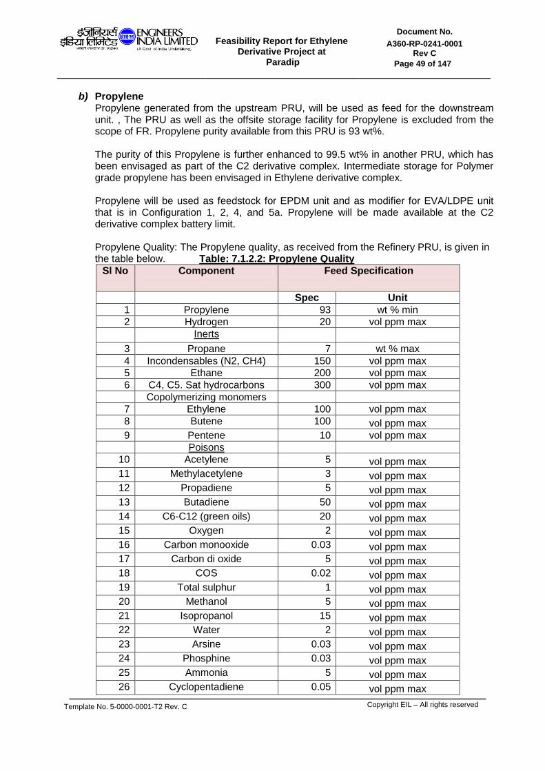
Feasibility Report for Ethylene
Derivative Project at Paradip
Document No.
A360-RP-0241-0001 Rev C
Page 49 of 147
Template No. 5-0000-0001-T2 Rev. C
Copyright EIL – All rights reserved
b) Propylene Propylene generated from the upstream PRU, will be used as feed for the downstream unit. , The PRU as well as the offsite storage facility for Propylene is excluded from the scope of FR. Propylene purity available from this PRU is 93 wt%. The purity of this Propylene is further enhanced to 99.5 wt% in another PRU, which has been envisaged as part of the C2 derivative complex. Intermediate storage for Polymer grade propylene has been envisaged in Ethylene derivative complex. Propylene will be used as feedstock for EPDM unit and as modifier for EVA/LDPE unit that is in Configuration 1, 2, 4, and 5a. Propylene will be made available at the C2 derivative complex battery limit. Propylene Quality: The Propylene quality, as received from the Refinery PRU, is given in the table below. Table: 7.1.2.2: Propylene Quality
Sl No Component Feed Specification
Spec Unit
1 Propylene 93 wt % min
2 Hydrogen 20 vol ppm max
Inerts
3 Propane 7 wt % max
4 Incondensables (N2, CH4) 150 vol ppm max
5 Ethane 200 vol ppm max
6 C4, C5. Sat hydrocarbons 300 vol ppm max
Copolymerizing monomers 7 Ethylene 100 vol ppm max
8 Butene 100 vol ppm max
9 Pentene 10 vol ppm max
Poisons 10 Acetylene 5 vol ppm max
11 Methylacetylene 3 vol ppm max
12 Propadiene 5 vol ppm max
13 Butadiene 50 vol ppm max
14 C6-C12 (green oils) 20 vol ppm max
15 Oxygen 2 vol ppm max
16 Carbon monooxide 0.03 vol ppm max
17 Carbon di oxide 5 vol ppm max
18 COS 0.02 vol ppm max
19 Total sulphur 1 vol ppm max
20 Methanol 5 vol ppm max
21 Isopropanol 15 vol ppm max
22 Water 2 vol ppm max
23 Arsine 0.03 vol ppm max
24 Phosphine 0.03 vol ppm max
25 Ammonia 5 vol ppm max
26 Cyclopentadiene 0.05 vol ppm max

Feasibility Report for Ethylene
Derivative Project at Paradip
Document No.
A360-RP-0241-0001 Rev C
Page 50 of 147
Template No. 5-0000-0001-T2 Rev. C
Copyright EIL – All rights reserved
c) Benzene Benzene is required as feed for the Ethyl Benzene unit (Configuration 4). Benzene is considered as a merchant purchase and same will be made available at the ethylene derivative complex battery limit. The benzene feed quality, as has been considered in the designing of EB unit, shall conform to the specification provided in the table below.
Table: 7.1.2.3: Benzene Quality
Sl No Parameter Specification UOM
1 Purity 99.80 wt% min
2 Toluene 1000 ppmw max
3 Non-aromatics 1000 ppmw max
4 Total Chlorides 1.0 ppmw max
5 Thiophene 1.0 ppmw max
6 Total Sulfur 1.0 ppmw max
7 Total Nitrogen Compounds
(ASTM-D6069 method) 1.0 ppmw max
8 Water (no free water) Saturated max
9 Carbon Disulphide 1.0 mg/L max
10 Copper Strip Corrosion Pass (1a or1b)
11 Bromine Index 0.2 mg/g max
12 Color 20 Pt-Co Scale max
13 Acid wash Color Pass with 1.0 max
14 Acidity None detected
15 Specific Gravity @ 15.56 deg C 0.882 – 0.886
16 Solidification Point 5.45 deg C min
17 Distillation range @ 760 mm Hg 1.0 (including 80.1 deg C) deg C max
d) Vinyl acetate.
For the production of ethylene-vinyl acetate copolymers (EVA’s), high purity vinyl acetate is required according to the following specification. VA will be used in Configuration 1 and 2 respectively. VA is considered as a merchant purchase and same will be made available at the ethylene derivative complex battery limit.
Table: 7.1.2.4: Vinyl Acetate Quality
Sl No Component Test method Requirement
1 Specific gravity at 20/20 degree celcius
ASTM 1298 0.9335-0.9345
2 Vinyl acetate content GC 99.9 wt% min
3 Acetaldehyde GC 100 wt ppm max
4 Acidity as Acetic acid ASTM D2086 50 wt ppm max
5 Hydroquinone ASTM D2193-84
Range 10-20 wt ppm
Water Water ASTM E203-75 300 wt ppm max (1)
Appearance Appearance Visual Colourless to light yellow. Free from foreign material
Colour APHA max
5
(1) Continuously maximum concentration of water is 100 wt ppm.

Feasibility Report for Ethylene
Derivative Project at Paradip
Document No.
A360-RP-0241-0001 Rev C
Page 51 of 147
Template No. 5-0000-0001-T2 Rev. C
Copyright EIL – All rights reserved
e) Ethylidene-Norbornene (ENB) ENB is used as a termonomer for the EPDM unit, in Configuration 2, 4 and 5a.respectively. ENB is considered as a merchant purchase and same will be made available at the ethylene derivative complex battery limit.
Table: 7.1.2.5: Ethylidene-Norborene (ENB) Quality
Sl no Composition Specification Unit
1 ENB % wt 98.5 min
2 Terminal vinyl anular compounds % wt 0.4 max
3 Other non-anular diolefins % wt 0.4 max
4 Cyclopentadiene % wt 0.1 max
5 Peroxides ppm wt 10 max
6 Water ppm wt 50 max
7 Inhibitor ppm wt 100 max
8 APHA colour 100 x
f) Extender oil Extender oil is used in the EPDM unit, in Configuration 2, 4 and 5a.respectively and is considered as a merchant purchase and will be made available at the ethylene derivative complex battery limit. The quality of Extender oil is provided below in the table.
Table: 7.1.2.6: Extender oil Quality
Sl no Composition Specification Unit
1 Type Paraffinic
2 Molecular weight 550 – 600
3 Density Kg/dm3 0.880 – 0.895
4 ASTM colour 4 max
5 Refractive index at 20 °C 1.48 – 1.49
6 Cinematic viscosity at 50 °C cSt 80 – 95
7 SUS viscosity at 210 °F cSt 13 – 17
8 Viscosity index 95 min.
9 Neutralization number Mg KOH/gr
0.1 max
10 Flash point °C 250 min.
11 Pour point °C -6 max
12 Aniline point °C 110 min.
13 Conradson residue % wt 0.3 max.
14 Polar compounds % wt 2 max.
15 Paraffinic C % wt 65 min.
16 Aromatic C % wt 8 max.
17 Distillation at 10 mmHg, 5% °C 270 min
g) Oxygen
Oxygen shall be used as feed for the Oxychlorination section of the EDC unit (Configuration 3, 5a,5b,5c,5d,5f,5g) and also as feed for the MEG unit (Configuration 6,

Feasibility Report for Ethylene
Derivative Project at Paradip
Document No.
A360-RP-0241-0001 Rev C
Page 52 of 147
Template No. 5-0000-0001-T2 Rev. C
Copyright EIL – All rights reserved
6A, 6B, 6C). As confirmed by IOCL, Oxygen required for the complex will be supplied over the fence, and will be made available the complex battery limit. The Oxygen quality, as required by EDC unit is provided in the table below.
Table: 7.1.2.7: Oxygen Quality
Sl no Composition Specification Unit
1 Oxygen 99.5 Vol % min
2 Nitrogen and Argon 0.5 Vol % max
The Oxygen quality, as required by MEG unit is provided in the table below.
Table: 7.1.2.8: Oxygen Quality
Sl no Composition Specification Unit
1 Oxygen 99.8 Vol % min
IOCL to ensure the availability of Oxygen conforming to the above quality from the Refinery ASU.
h) Hydrogen Hydrogen shall be used as molecular weight modifier for EVA/LDPE unit (Configuration 1,2 ), EPDM unit (Configuration 2,4,5a) and as reducing agent in EDC unit (Configuration 3). Hydrogen would be sourced from Paradip refinery and same will be made available at the ethylene derivative complex battery limit. . The Hydrogen quality, as required, is provided in the table below
Table: 7.1.2.9: Hydrogen Quality
Sl no Composition Specification Unit
1 Hydrogen 99.9 vol% min
2 CO + CO2 10 ppm vol max
3 N2 + CH4 0.05 vol% max
4 Water 5 Mg/Nm3 max
i) Import Ethylene Di Chloride
EDC shall be used as feed for the VCM unit (Configuration 5a, 5b, 5c, 5d, 5e, 5f, 5g) and will be supplied to the complex as merchant purchase. The quality of fed EDC, as required by the unit, is provided in the table below.
Table: 7.1.2.10: Import Ethylene Di Chloride Quality
Sl no Composition Specification Unit
1 State Liquid
2 Appearance Clear and Free of suspended Soild
3 Colour Colorless
C

Feasibility Report for Ethylene
Derivative Project at Paradip
Document No.
A360-RP-0241-0001 Rev C
Page 53 of 147
Template No. 5-0000-0001-T2 Rev. C
Copyright EIL – All rights reserved
4 Purity 99.90 Wt % min
5
Chlorohydrocarbons Low Boiling High Boiling
450 450
ppm Max ppm Max
6 Acidity(as Hcl) 5 ppm Max
7 Iron 0.5 ppm Max
8 Water 200 ppm Max
9 Non Volatile Residue 50 ppm Max
j) Nitrogen Nitrogen shall be used as Ballast gas in MEG unit, (Configuration 6). Nitrogen would be sourced from Paradip refinery and same will be made available at C2 derivative complex battery limit. The nitrogen quality, as available from the refinery is provided in the table below.
Table: 7.1.2.11: Nitrogen Quality
Sl no Composition Specification Unit
1 Nitrogen purity 99.99% vol (min)
% vol min
2 Dew point @ Atm press -80 °C o C
3 Carbon Monoxide 5 vol pp max
4 Carbon Dioxide 5 vol pp max
5 Oxygen content 10 vol pp max
6 Oil content Nil
k) Sodium Chloride
Sodium chloride shall be used as feed for the Electrolyser in Chlor alkali plant, Configuration 3. Sodium chloride is considered as a merchant purchase and shall be made available at C2 derivative complex battery limit, and its quality shall conform to that required by the Chlor alkali unit
7.1.3 PROJECT CONFIGURATION:
Following configurations were identified in the scope of work.
Table: 7.1.3.1: Original Project Configuration Envisaged
Conf Unit Capacity
1 ERU EVA / LDPE
230 KTPA of Ethylene 260 KTPA of Polymer Product with a split of EVA=130 KTPA, LDPE=130 KTPA
2 a
ERU EVA / LDPE
230 KTPA of Ethylene 185 KTPA of Polymer Product with a split of EVA=115 KTPA, LDPE=70 KTPA

Feasibility Report for Ethylene
Derivative Project at Paradip
Document No.
A360-RP-0241-0001 Rev C
Page 54 of 147
Template No. 5-0000-0001-T2 Rev. C
Copyright EIL – All rights reserved
EPDM 120 KTPA of Polymer product
2 b
ERU EVA / LDPE EPDM
230 KTPA of Ethylene 210 KTPA of Polymer Product with a split of EVA=120 KTPA, LDPE=90 KTPA 75 KTPA of Polymer product
3 ERU PVC
230 KTPA of Ethylene 500 KTPA of PVC
4 ERU EB/SM EPDM
230 KTPA of Ethylene 600 KTPA of styrene 100 KTPA of EPDM
However, in the course of the study and as an outcome of several meeting held between IOCL and EIL, additional thirteen number of configurations were examined with the intent of exploring the possibility of more attractive options for ethylene utilization. The list of all the eighteen (18) configuration, identified for the FR study, are described below
Table: 7.1.3.2: Updated Project Configuration
Conf Unit Feed Product
Capacity Remarks
1 (#)
ERU FCC off gas Ethylene ,C3 Product, C2 purge, Fuel gas
220 KTPA of Ethylene
EVA / LDPE Ethylene, VAM
EVA LDPE
230 KTPA of Polymer Product (EVA=70 KTPA, LDPE=130 KTPA)
2 (*)
ERU FCC off gas Ethylene ,C3 Product, C2 purge, Fuel gas
220 KTPA of Ethylene
(Note 9)
EVA / LDPE Ethylene, VAM EVA LDPE
200 KTPA of Polymer Product (EVA=60 KTPA, LDPE=140 KTPA)
EPDM Ethylene, Propylene, Hydrogen, ENB
EPDM 50 KTPA of EPDM
PRU 93 wt% Propylene from Refinery
99.5 wt% Propylene 17.3 KTPA of Propylene
3
ERU FCC off gas Ethylene ,C3 Product, C2 purge, Fuel gas
220 KTPA of Ethylene
(Note 1) Chlor Alkali Brine
Chlorine, Caustic, Hydrogen
285 KTPA of chlorine
EDC/VCM/PVC (Balanced process)
Ethylene, Oxygen, Chlorine
PVC 480 KTPA of PVC
4
ERU FCC off gas Ethylene ,C3 Product, C2 purge, Fuel gas
220 KTPA of Ethylene
(Note 2) EB/SM Ethylene, Benzene
Styrene’, BT by product Compressed off gas
600 KTPA of styrene
EPDM Ethylene, 81 KTPA of EPDM
C

Feasibility Report for Ethylene
Derivative Project at Paradip
Document No.
A360-RP-0241-0001 Rev C
Page 55 of 147
Template No. 5-0000-0001-T2 Rev. C
Copyright EIL – All rights reserved
Propylene, Hydrogen, ENB
EPDM
PRU 93 wt% Propylene from Refinery
99.5 wt% Propylene 34.3 KTPA of Propylene
5a
ERU FCC off gas Ethylene ,C3 Product, C2 purge, Fuel gas
220 KTPA of Ethylene
(Note 2)
EDC/VCM/PVC (**)
Ethylene, EDC, Oxygen, Chlorine
PVC 660 KTPA of PVC
EPDM Ethylene, Propylene, Hydrogen, ENB
EPDM
114 KTPA of EPDM
PRU 93 wt% Propylene from Refinery
99.5 wt% Propylene 48.2 KTPA of Propylene
5b
ERU FCC off gas Ethylene ,C3 Product, C2 purge, Fuel gas
220 KTPA of Ethylene
(Note 3) EDC/VCM/PVC (**)
Ethylene, EDC, Oxygen, Chlorine
PVC 660 KTPA of PVC
5c/5e
ERU FCC off gas Ethylene ,C3 Product, C2 purge, Fuel gas
220 KTPA of Ethylene
(Note 4,5) EDC/VCM/PVC (**)
Ethylene, EDC, Oxygen, Chlorine
PVC 440 KTPA of PVC
5d
ERU FCC off gas Ethylene ,C3 Product, C2 purge, Fuel gas
160 KTPA of Ethylene
(Note 6,7) EDC/VCM/PVC (**)
Ethylene, EDC, Oxygen, Chlorine
PVC 440 KTPA of PVC
5f
ERU FCC off gas Ethylene ,C3 Product, C2 purge, Fuel gas
150 KTPA of Ethylene
(Note 6,8) EDC/VCM/PVC (**)
Ethylene, EDC, Oxygen, Chlorine
PVC 440 KTPA of PVC
5g ERU FCC off gas
Ethylene ,C3 Product, C2 purge, Fuel gas
150 KTPA of Ethylene
(Note 6) EDC/VCM/PVC (**)
Ethylene, EDC, Oxygen, Chlorine
PVC 660 KTPA of PVC
6/6A /6B/6C
ERU FCC off gas Ethylene ,C3 Product, C2 purge, Fuel gas
220 KTPA of Ethylene
MEG Ethylene, Methane Oxygen
MEG, DEG, TEG 372 KTPA of MEG
4A/4B
ERU FCC off gas Ethylene ,C3 Product, C2 purge, Fuel gas
180 KTPA of Ethylene
EB/SM Ethylene, Benzene Styrene, BT by product Compressed off gas
600 KTPA of Styrene
(*) Based on the deliberation between EIL/IOCL and LYB/EMCTL Configuration 2a and 2b was rationalized to Configuration 2. (**) Unbalanced process (#) Base case for EVA: LDPE = 50:50 split has also been carried out. Note 1: PVC unit capacity brought down vis a vis scope of work, so as to match the ethylene generation capacity.
C

Feasibility Report for Ethylene
Derivative Project at Paradip
Document No.
A360-RP-0241-0001 Rev C
Page 56 of 147
Template No. 5-0000-0001-T2 Rev. C
Copyright EIL – All rights reserved
Note 2: EPDM unit capacity brought down vis a vis scope of work, so as to match the ethylene generation capacity. However, EPDM unit Capex is for 100 KTPA and 125 KTPA of EPDM in Configuration 4 and 5a respectively. Note 3: Of the total generated Ethylene, 150 KTPA will be consumed in the downstream EDC/VCM plant. 70 KTPA Ethylene will be routed to merchant sale. Note 4: Of the total generated Ethylene, 100 KTPA will be consumed in the downstream EDC/VCM plant. 120 KTPA Ethylene will be routed to merchant sale. Note 5: Configuration 5e is similar to 5c, except that plot provision for an additional future train of PVC (220 KTPA PVC product) has been considered in Configuration 5e. Note 6: In view of reduced ERU capacity, incoming FCC off gas to C2 derivative complex will be limited corresponding to the Ethylene product specified from ERU. Note 7: Of the total generated Ethylene, 100 KTPA will be consumed in the downstream EDC/VCM plant. 60 KTPA Ethylene will be routed to merchant sale Note 8: 440 KTPA VCM-PVC, with future provision (only land, no site development) for expansion to 660 KTPA. Ethylene required for 440 KTPA VCM-PVC and 660 KTPA VCM-PVC unit is 100 KTPA and 150 KTPA respectively. For FR purpose, CAPEX/OPEX for Utilities & Offsite shall be corresponding to 100 KTPA ERU / 440 KTPA VCM-PVC unit However Process unit Capex shall be based on 150 KTPA ERU and 440 KTAPA VCM-PVC. No Ethylene is produced for merchant Sale 7.1.3.1 Preliminary Block flow diagram for the above configurations are in Annexures as listed
below.
Annexure II : Block Flow diagram Configuration-1 Annexure III : Block Flow diagram Configuration -2 Annexure IV : Block Flow diagram Configuration -3 Annexure V : Block Flow diagram Configuration -4 Annexure VI : Block Flow diagram Configuration -5a Annexure VII : Block Flow diagram Configuration -5b Annexure VIII : Block Flow diagram Configuration -5c/5e Annexure IX : Block Flow diagram Configuration -5d Annexure X : Block Flow diagram Configuration -5f Annexure XI : Block Flow diagram Configuration -5g Annexure XII : Block Flow diagram Configuration -6 / 6A / 6B/ 6C 7.1.4 PRODUCT SLATE
The product slate for the various products of the Ethylene derivative complex is provided below:
7.1.4.1 EVA/LDPE
The following grades of LDPE & EVA were targeted for production at Paradip in line with the scope of work document.
C

Feasibility Report for Ethylene
Derivative Project at Paradip
Document No.
A360-RP-0241-0001 Rev C
Page 57 of 147
Template No. 5-0000-0001-T2 Rev. C
Copyright EIL – All rights reserved
Table: 7.1.4.1.a: EVA/LDPE Grades
Product Grades Percentage of total product
Application
EVA
Up to 20% VA Content 77 Footwear, sheet and packaging
20-25% VA Content 2 Hot Melt Adhesives
25-30% VA Content 13 Wires & cables, Hot Melt Adhesives
30-35% VA Content 3 Printing ink, Hot Melt Adhesives, solar cell encapsulation
more than 35% VA Content 6 Printing ink, Hot Melt Adhesives
LDPE
Edible grade (Film grade) 45
Non Edible grade (Film grade)
46
Injection Moulding Grades 5
Wire & Cables Grade 4
The Licensors Lyondell Basell (LYB) and Exxon Mobil (EMCTL) were contacted and Short NIT’s were sent to both the Licensors. Subsequently, teleconference and meeting were held by EIL/ IOCL with both LYB and EMCTL. During the course of discussion with the Licensors, following salient points emerged.
i) EVA resins up to 20% VA content cover about 80% of the total market volume.
ii) Major market in Asia for EVA (VA content: 18-22%) is shoe soles (28% of global market). The sheet and film market is also increasing, but it is limited. Sometimes EVA with 26-28% VA is used for shoe soles, but it is limited. Elastomers are blended with EVA for footwear. In India, around 100 KTA EVA is 2012 demand for shoe soles. Considering the Western Europe and American markets, the demand for EVA is in film sheets and lamination grades. EVA with 18 wt % VA content can be used for various purposes besides shoe soles, depending on the end use and the features required. For e.g. flexible hoses can be made with EVA ranging from 6-22% VA content.
iii) Market demand for the high % VA EVA is relatively small. EVA with high VA (>26 wt %) is mainly used in photovoltaic cell, adhesives and compounds.
iv) For above 22wt% VA content EVA, the challenge is producing the sticky product and
handling them especially in warm climate of Paradip. ISBL / OSBL cost as well as the transportation cost will increase. The capability to produce and handle high EVA resins requires expensive process modifications including additional capacity for chilled water, increased number of degassing silos,

Feasibility Report for Ethylene
Derivative Project at Paradip
Document No.
A360-RP-0241-0001 Rev C
Page 58 of 147
Template No. 5-0000-0001-T2 Rev. C
Copyright EIL – All rights reserved
facilities/measure for antiblocking pellet treatment, thermal insulation of conveying and product storage etc. For high VA EVA, pelletization is difficult as also high amount of cost is associated with finishing section. So, high VA requires more extruder investment and higher refrigeration load and is more operationally difficult on large capacity lines.
High (>22 wt% VA) products do not have that good premium when seen against the operational challenges.
v) The LDPE grade slate targeted is aimed for tubular reactor products, autoclaves are not cost competitive for most film grades. Autoclave reactors are not as competitive for film grade LDPE products (tubular reactors have better operating costs for film grade LDPE)
vi) Autoclaves are particularly well suited for LDPE extrusion coating; however, there is no extrusion coating in the requested grade slate.
vii) Autoclave reactor is of smaller capacity as compared to tubular reactor. Autoclave reactor size is typically limited to 140 KTPA.
viii) Capex for tubular reactor with capacities 155 KTPA and 180 KTPA will be only marginally less than 200 KTPA tubular reactor.
Based on the discussion with Licensors, EIL/IOCL decided that following will be adopted for FR purpose.
A) Grades targeted for EVA to be restricted to EVA with 22 % VA content. B) 30%:70% EVA: LDPE production split. C) Tubular reactor will be considered. D) Configuration 2a and 2b was revised to Configuration 2.
7.1.4.2 EPDM
Based on inputs received from IOCL, the following grades of EPDM were targeted for production at Paradip
Table: 7.1.4.2.a: EPDM Grades
Product Grades Percentage of total product
Application
EPDM
Automobiles 51.7 Tyre & tubes, Various body and chassis parts, radiator & heater hoses, window weather stripping, weather seals etc
Building & Construction 27.6 Roofing foils, seals, curtain wall glazing, expansion joints, Architectural gaskets, single ply roof membranes etc
Wire & cables 6.9
Mechanical Rubber goods 6.9 Diaphragm, valve, insulator, seals etc

Feasibility Report for Ethylene
Derivative Project at Paradip
Document No.
A360-RP-0241-0001 Rev C
Page 59 of 147
Template No. 5-0000-0001-T2 Rev. C
Copyright EIL – All rights reserved
Miscelleneous Applications 6.9 Solar pool panels, lubricant additives, plastic modifications etc
The Licensors Sumitomo (SC) and Fastech were contacted for EPDM unit and Short NIT’s were sent to both the Licensors. Subsequently, teleconference and meeting were held with both Sumitomo and Fastech. During the course of discussion with the Licensors, the following points emerged,
A) Fastech can offer all of the EPDM grade as listed above.
B) Sumitomo will offer all of the above EPDM grades except Wire and Cable grade EPDM.
Thus, for the FR study all of the above EPDM grades have been considered.
7.1.4.3 PVC
Based on inputs received from IOCL, the following grades of PVC were targeted for production at Paradip
Table: 7.1.4.3.a: PVC Grades
Product Grades Percentage of total product
Application
PVC
Suspension Grade 91.0 Pipes and conduits, wires and cables, Films and sheet, profiles, footwear etc
Paste Grade 5.7 Synthetic leather, tarpaulin, flooring, wall covering, conveyor belts, balls, toys, protective gloves etc
Battery Separator Grade 2.0
Co-polymer Grade 1.2 Vinyl printing Inks & solvent cements, Floor tiling, Vinyl asbestos tiles.
The Licensors Ineos and JNC were contacted for PVC unit (of Configuration 3) and Short NIT’s were sent to both the Licensors. Subsequently, teleconference, meeting were held with both Ineos and JNC. The outcomes of the meeting are summarized below:
A) Ineos can offer only suspension grade PVC.
B) JNC can offer Suspension grade and Co Polymer grade PVC.
C) However none of the Licensor will offer Paste Grade and Battery Separator grade
Product.
As informed by IOCL, Licensor Hanwha Chemical (HCC) shall be the single point contact of IOCL for obtaining the licensed technology of EDC/VCM/PVC unit corresponding to Configuration 5a, b, c, d, f, and g. The targeted grade slate for PVC from the Ethylene derivative complex was communicated to HCC.

Feasibility Report for Ethylene
Derivative Project at Paradip
Document No.
A360-RP-0241-0001 Rev C
Page 60 of 147
Template No. 5-0000-0001-T2 Rev. C
Copyright EIL – All rights reserved
HCC clarified that technically HCC can offer all the four grades required tabulated above. However for FR purpose, HCC has considered only “Suspension Grade” because for the other three types of grades, Indian market share is not sufficient to justify the additional capex/opex required. Hence, in view of the above, only suspension grade PVC was considered for FR.
7.1.4.4 Styrene monomer The Styrene monomer product will meet the following guaranteed specification.
Table: 7.1.4.4a: Styrene monomer specification
Sl No Composition Performance guarantee specification
Minimum guarantee specification
Unit
1 Purity(dry basis) 99.97 99.95 wt% min
2 Ethylbenzene 50 50 ppmw max
3 AlphaMethyl Styrene 150 150 ppmw max
4 C8/C9 Aromatics 300 300 ppmw max
5 Non-aromatics 100 100 ppmw max
6 Phenyl Acetylene 50 ppmw max
7 Aldehydes (as Benzaldehyde) 50 ppmw max
8 Peroxides (as H2O2) 15 ppmw max
9 Total Sulphur 1 ppmw max
10 Inhibitor (TBC) 15 ppmw max
11 Chlorides (as Cl) 2 ppmw max
12 Benzene 1 ppmw max
13 Moisture 100 ppmw max
14 Xylene 65 65 ppmw max
15 Polymer 5 ppmw max
16 Color 10 APHA max
17 Density @ 15oC 0.909-0.911 g/ml
7.1.4.5 MEG The SD process based MEG plant shall be able to meet the following product specification of MEG.
Table: 7.1.4.5a: MEG specification
Sl no Characteristics Specification
1 Appearance Clear, colorless
2 Odour Characteristic
3 MEG content, wt% min 99.9
4 DEG content, wt% max 0.04
5 Specific gravity @ 20/20 deg C 1.1151-1.1156

Feasibility Report for Ethylene
Derivative Project at Paradip
Document No.
A360-RP-0241-0001 Rev C
Page 61 of 147
Template No. 5-0000-0001-T2 Rev. C
Copyright EIL – All rights reserved
6
Distillation range @ 760 mmHG
IBP deg C min 196
EP deg C 199
5-95 vol% range deg C max 1
7 Refractive index @ 20 deg C 1.4310-1.4320
8 Water, wt% max 0.04
9
Color, Pt-Co units
Before heating, max 5
After 4 hours boiling, max 10
10 Acidity (as Acetic acid), wt ppm
max 10
11 Chlorides (as Cl), wt ppm max 0.1
12 Sulphates Nil
13 Miscibility in water Fully Miscible
14 Iron wt ppm max 0.05
15 Ash, wt ppm max 10
16 Aldehydes (as Formaldehyde) wt
ppm max 8
17
Transmission in ultraviolet wave length (nm)
220 Transmission %, min 90
275 Transmission %, min 95
350 Transmission %, min 99

Feasibility Report for Ethylene
Derivative Project at Paradip
Document No.
A360-RP-0241-0001 Rev C
Page 62 of 147
Template No. 5-0000-0001-T2 Rev. C
Copyright EIL – All rights reserved
SECTION 7.2
TECHNOLOGY OPTIONS

Feasibility Report for Ethylene
Derivative Project at Paradip
Document No.
A360-RP-0241-0001 Rev C
Page 63 of 147
Template No. 5-0000-0001-T2 Rev. C
Copyright EIL – All rights reserved
7.2 TECHNOLOGY OPTIONS The list of process licensors for all the units of the Ethylene derivative complex are as given below. All the listed process licensors are of international repute and have wide proven experience in design, construction and operation of similar plants worldwide.
Table: 7.2.1: Process Licensors
Serial No
Unit Licensors Remarks
1 ERU ABB Lummus
Note 1
2 EB/SM ABB Lummus
Note 1
3 EVA/LDPE Lyondell Basell
Exxon Mobil Note 2
4 EPDM Sumitomo Fastech
Note 3
5 EDC/VCM (Balanced)
Ineos Note 4
6 PVC Ineos JNC
Note 5
7 EDC/VCM/PVC (Unbalanced)
Hanhwa chemical
Note 6
8 MEG Scientific Design
Note 7
Note 1 Both ERU and EB/SM units have been licensed by M/S ABB Lummus. As per the scope of work, the plant and machinery cost and operating cost for ERU and EB/SM units have been carried out based on the available design data with IOCL. The necessary data required for costing of these two units have been provided by IOCL. Hence, no other Licensors have been contacted for these two units.
The present BDEP for ERU is to be augmented for producing polymer grade ethylene. Data corresponding to augmentation is incorporated in the FR.
Note 2 The Licensors M/S Lyondell Basell (LYB) and M/S Exxon Mobil (EMCTL) were contacted
and Short NIT’s were sent to both the Licensors. Subsequent to this, several tele conversations were held followed by exchanges of data. The following points emerged as an outcome of several discussions with both the Licensors.
a) Specific consumption of raw material and utility for both the Licensors are similar. b) Equipment level data have been provided by both the Licensor. However, EMCTL
equipment level data as compared to LYB data is more complete.
Thus in view of the above, the Capex ,Opex ,Revenue and other calculation have been carried out with M/S EMCTL data for the Feasibility study.
Note 3 The Licensors M/S Sumitomo and M/S Fastech were contacted and Short NIT’s were sent to both the Licensors. Subsequent to this, several tele conversation was held followed by exchanges of data. The following points emerged as an outcome of several discussion held with both the Licensors.

Feasibility Report for Ethylene
Derivative Project at Paradip
Document No.
A360-RP-0241-0001 Rev C
Page 64 of 147
Template No. 5-0000-0001-T2 Rev. C
Copyright EIL – All rights reserved
a) Equipment level data suitable for costing, have been provided only by Fastech. Sumitomo has provided Total installed Cost for the unit. Sumitomo refused to provide equipment level cost data without signing License agreement. Thus equipment level costing for EPDM unit has been carried out with Fastech data.
b) Configuration required by IOCL is: 75 KTPA, 100 KTPA and 120 KTPA EPDM plant. Sumitomo has offered 1X75 KTPA, 2X50 KTPA and 2X60 KTPA EPDM train respectively. It may be noted that Sumitomo is having PTR for a maximum of 25 KTPA EPDM train.
c) Fastech is having PTR for a maximum of 25 KTPA EPDM train, and is offering trains in multiple of 25 KTPA for the various configuration of the Ethylene derivative complex.
Thus in view of the above points, the Capex ,Opex ,Revenue and other calculation have been carried out with M/S Fastech data and M/S Fastech configuration for the Feasibility study.
Note 4 For the balanced EDC/VCM unit, adequate data required for equipment level costing,
material balance, utility numbers have been provided by M/S Ineos. Thus, Capex ,Opex ,Revenue and other calculation have been carried out with M/S Ineos data for the Feasibility study
Note 5 The Licensors M/S Ineos and M/S JNC were contacted and Short NIT’s were sent to
both the Licensors. Subsequent to this, several tele conversation was held followed by exchanges of data. The following points emerged as an outcome of several discussions with both the Licensors.
a) Specific consumption of raw material and utility for both the Licensors are similar. b) Equipment level data suitable for costing have been provided by both the Licensor.
Capex, Opex, Revenue and other calculation have been carried out with M/S Ineos data for the Feasibility study
Note 6 Data required for capex opex estimation have been carried out with the data obtained
from M/S HCC. Note 7 Data of M/S Scientific Design for MEG unit, provided by IOCL , has been considered
for capex opex estimation of the unit.

Feasibility Report for Ethylene
Derivative Project at Paradip
Document No.
A360-RP-0241-0001 Rev C
Page 65 of 147
Template No. 5-0000-0001-T2 Rev. C
Copyright EIL – All rights reserved
SECTION 7.3
PROCESS DESCRIPTION
Feasibility Report for Ethylene
Derivative Project at Paradip
Document No.
A360-RP-0241-0001 Rev C
Page 66 of 147
Template No. 5-0000-0001-T2 Rev. C
Copyright EIL – All rights reserved
7.3.1 ETHYLENE RECOVERY UNIT 7.3.1.1 Process Chemistry
The purpose of the Low Pressure Ethylene Recovery (ER) Unit is to remove impurities found in the FCC off gas and to recover the ethylene for use in the downstream units to make value added polymers..
7.3.1.2 Process Description
The ER Unit is divided into the following areas:
Feed Treatment Area
The contaminants in the FCC offgas will be removed before the feed is processed in the downstream distillation area. The feed is first sent to the lower bed of the Caustic/Water Wash Tower where the H2S in the feed is removed and the amount of CO2 is reduced. Next the feed goes through a Chloride Treater to remove chlorides. After the Caustic Tower and Chloride Treater and adsorber the feed goes to the Oxygen Converter where the following reactions take place: Oxygen + Hydrogen Water Nitrogen Oxides + Hydrogen Ammonia + Water Acetylene + Hydrogen Ethylene + Ethane MAPD + Hydrogen Propylene + Propane Butadiene + Hydrogen Butene + Butane Undesired Side Reactions: Ethylene + Hydrogen Ethane Propylene + Hydrogen Propane The ethylene losses in the converter will be less than or equal to 1% of the ethylene in the feed stream. The offgas from the Oxygen Converter is routed to the upper bed of the Caustic/Water Wash Tower to remove any remaining acid gases. The offgas is then chilled before being sent to the Dryer/Treater to remove the water, mercaptans, ammonia, and amines. Finally, the feed goes through a Mercury Adsorber where the mercury is removed.
Distillation Area The feed is then sent to the FCC Offgas Chiller, located in the Cold Box, where a binary refrigerant is used to chill the feed. After being chilled it is then sent to the Demethanizer. The Demethanizer is provided with an intercooler using binary refrigerant to minimize the ethylene losses. In the Demethanizer the FCC offgas fed into the lower part of the tower is contacted against a side draw stream from the Deethylenizer, which enters at the top of the tower. The overhead stream from the Demethanizer is used as regeneration gas for the Dryer/Treaters and then sent to OSBL to be used as refinery fuel gas. The Demethanizer bottoms stream is sent to the Deethylenizer. The Deethylenizer overhead is fully condensed using binary refrigerant and produces 99.5 wt % ethylene. The liquid ethylene product is then sent to the Offsite. A small ethylene product stream is
C
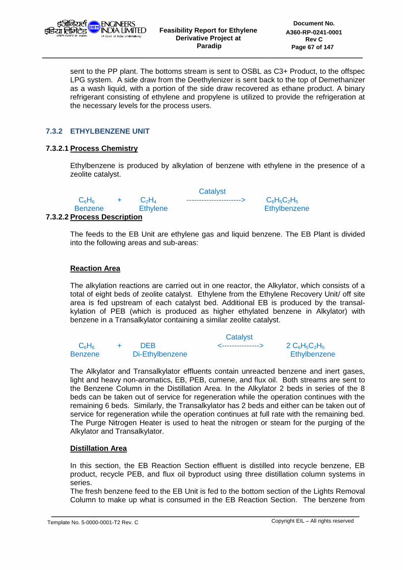
Feasibility Report for Ethylene
Derivative Project at Paradip
Document No.
A360-RP-0241-0001 Rev C
Page 67 of 147
Template No. 5-0000-0001-T2 Rev. C
Copyright EIL – All rights reserved
sent to the PP plant. The bottoms stream is sent to OSBL as C3+ Product, to the offspec LPG system. A side draw from the Deethylenizer is sent back to the top of Demethanizer as a wash liquid, with a portion of the side draw recovered as ethane product. A binary refrigerant consisting of ethylene and propylene is utilized to provide the refrigeration at the necessary levels for the process users.
7.3.2 ETHYLBENZENE UNIT 7.3.2.1 Process Chemistry
Ethylbenzene is produced by alkylation of benzene with ethylene in the presence of a zeolite catalyst. Catalyst C6H6 + C2H4 ----------------------> C6H5C2H5 Benzene Ethylene Ethylbenzene
7.3.2.2 Process Description
The feeds to the EB Unit are ethylene gas and liquid benzene. The EB Plant is divided into the following areas and sub-areas:
Reaction Area The alkylation reactions are carried out in one reactor, the Alkylator, which consists of a total of eight beds of zeolite catalyst. Ethylene from the Ethylene Recovery Unit/ off site area is fed upstream of each catalyst bed. Additional EB is produced by the transal-kylation of PEB (which is produced as higher ethylated benzene in Alkylator) with benzene in a Transalkylator containing a similar zeolite catalyst. Catalyst C6H6 + DEB <---------------> 2 C6H5C2H5 Benzene Di-Ethylbenzene Ethylbenzene The Alkylator and Transalkylator effluents contain unreacted benzene and inert gases, light and heavy non-aromatics, EB, PEB, cumene, and flux oil. Both streams are sent to the Benzene Column in the Distillation Area. In the Alkylator 2 beds in series of the 8 beds can be taken out of service for regeneration while the operation continues with the remaining 6 beds. Similarly, the Transalkylator has 2 beds and either can be taken out of service for regeneration while the operation continues at full rate with the remaining bed. The Purge Nitrogen Heater is used to heat the nitrogen or steam for the purging of the Alkylator and Transalkylator.
Distillation Area
In this section, the EB Reaction Section effluent is distilled into recycle benzene, EB product, recycle PEB, and flux oil byproduct using three distillation column systems in series. The fresh benzene feed to the EB Unit is fed to the bottom section of the Lights Removal Column to make up what is consumed in the EB Reaction Section. The benzene from

Feasibility Report for Ethylene
Derivative Project at Paradip
Document No.
A360-RP-0241-0001 Rev C
Page 68 of 147
Template No. 5-0000-0001-T2 Rev. C
Copyright EIL – All rights reserved
the Lights Removal Column bottoms is preheated by the Benzene Column bottoms in the Benzene Feed Heater. EB Reaction Section effluents from Alkylator and Transalkylator are fed to Benzene Column. A fired heater is used to reboil the Benzene Column. The column bottoms liquid is circulated like a heat transfer oil for reboiling in EB Column and PEB Column and for heating Lights Removal Column bottoms. Fresh benzene is fed to the Lights Removal Column. Vapor streams taken from the Benzene Column Drum are sent to the Lights Removal Column system. The Lights Removal Column removes from the process the non-condensable impurities from the ethylene feed. These are vented to fuel gas as the Lights Removal Column vapor vent. The EB Column system consists of the EB Column and associated reboiler and condenser. The EB product is recovered as the overhead product from the column. Diethylbenzene concentration in the product EB is kept to less than 5 wppm. The EB product is sent to the SM Unit or to OSBL storage. The EB column bottoms are fed to the PEB Column. The PEB recycle to the EB Reaction Section is recovered as the overhead product from the column. The high-boiling bottoms are cooled in the Flux Oil Cooler and sent to Flux Oil Scrubber and Wiped Film Evaporator in the SM Unit. The reboiler uses Benzene Column bottoms liquid as a heating medium and the column overhead vapor is condensed by preheating benzene feed from the OSBL and then in an air cooler. The EB Slop Cooler is used to cool off-spec streams and drains from process equipment that are sent to EB Slop Drum and then pumped out.
7.3.3. STYRENE MONOMER UNIT
The SM Plant is divided into the following areas-
7.3.3.1 Dehydrogenation Area In the Dehydrogenation Section, ethylbenzene (EB) is catalytically dehydrogenated to styrene (SM) in the presence of steam in a two-stage adiabatic reactor system. This endothermic (heat absorbing) reaction is equilibrium limited as: C6H5C2H5 C6H5C2H3 + H2 Ethylbenzene Styrene Hydrogen The reaction section is comprised of the EB/Water Vaporizing, Feed Superheater, and the Dehydrogenators. Liquid EB from the EB Unit plus Recycle EB from the Distillation Section and process condensate are fed to the EB Separator Drum. Some flashing of the feed occurs and the two liquid phases (EB and water) separate. The majority of each phase is pumped separately to the EB/SM Splitter Condenser in the SM Distillation Area, which serves as a vaporizer. The balance of the liquids is vaporized in the EB/Water Vaporizer, for trim control. Liquid and vapor return to the EB Separator Drum from the aforementioned condenser. A small blowdown of EB from the drum is taken to remove non-volatiles such as styrene polymer. The EB/steam vapor mixture is superheated by interchange with the Second Stage Dehydrogenator effluent in the EB Superheater and fed to the First Stage Dehydrogenator inlet, where it mixes with the superheated main steam feed. The EB/steam mixture enters the first stage catalyst bed in radial outward flow where a portion of the EB converts to SM. Most of the EB is converted to SM (limited by equilibrium) and to side products. The reaction system effluent is cooled by

Feasibility Report for Ethylene
Derivative Project at Paradip
Document No.
A360-RP-0241-0001 Rev C
Page 69 of 147
Template No. 5-0000-0001-T2 Rev. C
Copyright EIL – All rights reserved
superheating EB/Water vapor feed and generating LP steam in the Low Pressure Waste Heat Exchanger and LLP steam in the Low Low Pressure Waste Heat Exchanger. Liquid condensed in the Main Condenser, Trim Cooler, Stripper Overhead/Feed Interchanger, Offgas Cooler and PSA Feed Compressor interstage coolers flows to the DM/Water Separator. In the DM/Water Separator, the aromatics and process condensate form two liquid phases. The aromatic phase (Dehydrogenation Mixture or DM) overflows into an organics compartment and is pumped to the phenylacetylene removal (PAR) system. In this section, phenylacetylene, present in the dehydrogenated mixture (DM), is partially saturated to styrene. This reaction occurs in a liquid phase over a solid catalyst at modest temperatures and pressures. Some side reactions occur, notably the hydrogenation of styrene to ethylbenzene. Catalyst C6H5C2H1 + H2 C6H5C2H3 Phenylacetylene + Hydrogen Styrene The PAR system is included to achieve the SM purity of 99.97 wt%. The DM is then sent to the SM Distillation section. The aqueous phase (process condensate) separates by gravity in the main compartment of the DM/Water Separator and is pumped through the Skimming Tank to the Process Condensate Stripper system to remove entrained organics.
7.3.3.2 DM Distillation Area
The purpose of the DM Distillation Area is to fractionate the liquid mixture of aromatic compounds (DM) from the Dehydrogenation Area into: (a) a high-purity styrene product (b) an EB stream for recycles to the Dehydrogenation Area, (c) a styrene tar stream and (d) a benzene-toluene byproduct stream. The water-saturated DM is fed to the EB/SM Splitter. The overhead product stream from the Splitter (containing benzene, toluene, and almost all of the EB entering with the feed is fed to the EB Recovery Column. The EB Recovery Column bottoms product is recycled to the Dehydrogenation Area. The overhead product from the EB Recovery Column, a benzene-toluene mixture is cooled and sent to OSBL as a by-product. The bottoms stream from the EB/SM Splitter, containing almost all of the styrene from the column feed, the compounds boiling higher than SM, the polymerization inhibitors, a small amount of EB, and any styrene polymer made in the Stripper is fed to the SM Column. The SM Column bottoms stream, containing about 50 wt% volatiles, is sent to the Wiped Film Evaporator. The evaporator vaporizes the volatiles and returns them to the bottom of the SM Column.
7.3.4 EVA/LDPE UNIT
Polymerization grade ethylene is supplied to the battery limit and is boosted to 30 MPag by the primary compressor and cooled and divided into two streams. One stream is fed to the secondary compressor suction, while the other is added to the ethylene-polymer mixture downstream of the reactor pressure control valve (also known as the high pressure letdown valve) at the end of the reactor as "low pressure cold quench". In the suction manifold of the secondary compressor, the gas from the high pressure recycle system, chain transfer agent/ modifier and/or co-monomer (such as VA monomer) are combined with the ethylene from the primary compressor. The secondary compressor will then boost the pressure to the reactor operating pressure i.e. 250-310 MPag for the tubular reactor. The ethylene mixture then flows to the reactor system (tubular) where mixtures of organic peroxides diluted in hydrocarbon solvent are injected

Feasibility Report for Ethylene
Derivative Project at Paradip
Document No.
A360-RP-0241-0001 Rev C
Page 70 of 147
Template No. 5-0000-0001-T2 Rev. C
Copyright EIL – All rights reserved
to initiate the exothermic polymerization reaction. For tubular reactors, the discharge flow of the secondary compressor is divided in the number of streams required for the front and side streams of the reactor. The side stream flows are then fed to injection points along the length of the tubular reactor. In essence, the tubular reactor is a plug flow reactor. The peroxides initiate the free radical, exothermic polymerization reaction. The conversion of ethylene to polymer is maximized by the use of reactor jacket water at cooling water temperatures. After polymerization, the reaction fluid is decompressed through the reactor pressure control valve to about 30 MPag and cooled with the low pressure cold quench from the primary compressor discharge. The mixture is then fed to the high pressure separator where polymer is separated from un-reacted ethylene. The molten polymer and a small amount of entrained ethylene are again decompressed to approx. 0.07 MPag through the low pressure letdown valve and fed to the low pressure separator. At this point most of the remaining entrained ethylene is separated from the LDPE and is sent to the purge gas compression system. The purge gas compressor boosts the low pressure separator off-gas to the suction pressure of the primary compressor. The polymer melt from the low pressure separator is fed to the hot melt extruder. In the hot melt extruder additives are mixed in. The polymer strands leaving the die of the extruder are underwater cut into pellets. The pellets are cooled, dried and pneumatically transferred to weigh bins or blenders, in which the pellets are purged to reduce the residual ethylene concentration to a safe to store/package concentration (<15 ppm). After blending the pellets are conveyed to bulk loading or bagging facilities.
7.3.5 ETHYLENE PROPYLENE DIENE MONOMER UNIT
7.3.5.1 Process Chemistry
Polymerization of olefins and diene with solvent as reaction medium, the catalyst system consist of catalyst, activator, co-catalyst and M-W regulator under 15kg/cm2G pressure and temperature 40-60deg.C.
7.3.5.2 Process Description
Polymerization Section Ethylene, propylene, diene, hydrogen, solvent and catalyst component are continuously fed to reactors, which are equipped with a special stirrer for agitating high-viscosity reactants effectively.
Degassing The solution is continuously discharged into a degasser where the unreacted light monomers are removed. Evaporated monomers are then compressed and recycled to the reactor, while the unreacted ENB goes on together with the polymer solution.
Washing The solution, with polymer and unreacted ENB, is sent to the washing section; here polymer is washed, in two stages, by water and chemicals, in order to minimize the catalyst residual on polymer.
Stripping After the washing section, purified polymer solution is sent to the steam-stripping section to separate hexane and unreacted monomers from the polymer. The vapors leaving the strippers are partially condensed (hexane, steam and ENB) while the incondensable gas (ethylene, propylene etc.) are compressed and then sent to distillation and recovery section.
Finishing

Feasibility Report for Ethylene
Derivative Project at Paradip
Document No.
A360-RP-0241-0001 Rev C
Page 71 of 147
Template No. 5-0000-0001-T2 Rev. C
Copyright EIL – All rights reserved
The aqueous slurry coming from the last stripper is fed to a vibrating screen for the first water separation, subsequently to an expeller, to further separate water by mechanical squeezing action and then to an expander-dryer provided with a cut device. The obtained polymer granules are dried and cooled in cold box and spiral elevator and then conveyed to the packaging section, where they are compressed in bales.
Recovery The condensate coming from the strippers, after water separation by decanting, is fed to the distillation to separate and recover heavy fraction (ENB and hexane). After distillation, both ENB and hexane, undergo a drying process through molecular sieves columns.
7.3.6 POLY VINYL CHLORIDE UNIT
7.3.6.1 Process Chemistry
Vinyl Chloride Monomer (VCM), which boils at -13.4 C at atmospheric pressure, is polymerised in a batch process by dispersing the monomer in water under its own pressure in a stirred reactor. The reactor contents are heated to the required temperature (typically 56.5°C): the initiator then starts to decompose to give free radicals and the monomer in the droplets starts to polymerise. The reaction is exothermic, and the heat passes into the water and is removed by two methods: circulated cooling water in the jacket and cooling water in a condenser on the reactor top. PVC is insoluble in its monomer and once formed, precipitates out in the monomer droplets as submicron
particles.
7.3.6.2 Process Description
Polymerisation A specified amount of cooled demineralised water being sealed with nitrogen gas in the tank is charged along with the suspending agent into Reactor through a batch meter. The catalysts solution is fed into Reactor. The specified amount of VCM is also fed into Reactor through a batch meter. The reactor contents are violently stirred in Reactor, keeping the good suspension condition. After charging of VCM, a specified amount of hot demineralised water is charged into Reactor so that temperature of the Reactor contents could reach the set polymerization temperature. Then, cooling water is supplied into Reactor jacket, baffles and Reflux Condenser at high rate. The temperature of the reactor contents is so automatically controlled as to be constant at the set polymerization temperature by adjusting the flow rate of the cooling water. The PVC slurry in Reactor is blown down through Slurry Discharge Pump into Blow Down Tank, while recovering the un-reacted VCM gas from Reactor and Blow Down Tank into VCM Gas Holder. The slurry in Blow down Tank is fed to the Slurry Stripping section through Stripping Slurry Feed Pump. Slurry Degassing The PVC slurry in Reactor is blown down through Slurry Discharge Pump, into Blow Down Tank, while recovering the un-reacted VCM gas from Reactor and Blow Down Tank into VCM Gas Holder. The slurry in Blow Down Tank is fed to the Slurry Stripping section through Stripping Slurry Feed Pump. Slurry Stripping After degassing in the Stripper Feed Vessel, the slurry contains 2-3 % of the original VCM charge. In Stripping Column, the slurry passes over a series of trays where it is stripped with a counter current flow of steam from a 4-6 barg supply. VCM passes to the LP Recovery Compressors for recovery. From the base of the column the slurry is pumped through the Spiral Heat Exchanger to preheat the feed and cool the slurry

Feasibility Report for Ethylene
Derivative Project at Paradip
Document No.
A360-RP-0241-0001 Rev C
Page 72 of 147
Template No. 5-0000-0001-T2 Rev. C
Copyright EIL – All rights reserved
before it goes to the slurry tank. The slurry from the stripping column then passes to the slurry storage tank. Dryer Slurry from the Slurry Tank is circulated via a ring main to the centrifuges where it is dewatered to produce a moist PVC powder. The moist PVC powder then passes to the Dryer. There are two options for the Drying Technology to be used: either a two stage Flash/Fluid Bed Dryer, or a Contact Fluid Bed Dryer. The polymer then overflows to the vibrating screens for removal of any oversize material. VCM Recovery In this section, the unreacted VCM is recovered and treated for reuse. The unreacted VCM recovered from Polymerization section and Slurry Stripping section into VCM Gas Holder is compressed by VCM Compressors. VCM dissolved in waste water is stripped out by means of steam-stripping by steam fed to the bottom of Column during falling down from top to bottom. Water vapour and VCM leaves from the top of column and water vapour is condensed in Waste Water Condenser and uncondensed VCM is recovered and returned to Gas Holder. VCM stripped waste water is sent from the bottom of Column to Battery Limit by Waste Water Discharge Pump after being cooled through Waste Water Heat Exchanger. Product Handling Screened material from the screens is conveyed to the bagging hoppers. A medium phase blowing system is used, and two bagging hoppers. The filled bags are transferred from Bagging Machine to Palletizer through the conveyor, piled automatically up on the pallet and stored in existing product warehouse.
7.3.7 EDC/VCM UNIT (UNBALANCED UNIT)
7.3.7.1 Process Chemistry EDC is thermally dehydrochlorinated (cracked) to VCM and Hydrogen Chloride (HCl). VCM is recovered as high purity monomer suitable for storage or shipment in carbon steel vessels and suitable for polymerization to all grades of Polyvinyl Chloride (PVC) without further purification. The coproduct HCl is recovered as gaseous, high purity, anhydrous HCl at a pressure suitable for direct feed to the Oxychlorination process.
7.3.7.2 Process Description
Oxyhydrochlorination The Oxychlorination (OHCl) process combines HCl with ethylene and oxygen to produce ethylene dichloride (EDC). Ethylene and hydrogen chloride feeds flow upward through the Reactor and in the presence of the fluidized catalyst react to produce EDC according to the following reaction: C2H4+ 2HCl + 1/2 O2 C2H4Cl2 + H2O Ethylene + HCl + Oxygen EDC + Water + Heat The HCL received from the VCM recovery and purification section contains a small amount of acetylene that is reacted with hydrogen to form ethylene and a small amount of ethane in the HCl hydrogenation reactor. This oxy chlorination reaction is highly exothermic and takes place at a temperature of 220 to 240oC in a fluid bed of catalyst impregnated with cupric chloride. To ensure maximum conversion and high purity product EDC, the reaction temperature is closely controlled by the use of the fluid bed reactor. The reaction products are recovered by condensation in the recovery unit. The gases leaving the reactor pass through a quench column where un-reacted HCl is
Feasibility Report for Ethylene
Derivative Project at Paradip
Document No.
A360-RP-0241-0001 Rev C
Page 73 of 147
Template No. 5-0000-0001-T2 Rev. C
Copyright EIL – All rights reserved
scrubbed out with a recycle water stream. The scrubbed gases emerging from the top of the quench column pass through a crude EDC condenser where they are cooled and the bulk of the EDC and water is condensed. The EDC and water phases are stripped with a small amount of nitrogen in the CO2 Stripper to remove dissolved carbon dioxide, and then separated in the crude EDC decanter. EDC Recovery A small portion of the cooled vent gas stream then passes through a chiller where additional EDC and water are condensed. The vapor/liquid mixture from the chiller flows to a separator. The liquid from the separator flows by gravity to the crude EDC decanter. The gaseous phase is discharged to the vent gas incinerator. The portion of the cooled gases which does not go to the chiller is directed to the recycle gas compressor (PC-112) for compression prior to recycle back to the Oxychlorination reactor. EDC Manufacturing and Purification The EDC purification unit consists of three distillation columns which separate water, light ends, and heavy ends from the crude EDC in order to supply purified EDC to the EDC cracking furnaces.
EDC Cracking Purified EDC is fed to the EDC pyrolysis (cracking) furnaces where it is thermally cracked to vinyl chloride and hydrogen chloride by the following equation: C2H4Cl2 C2H3Cl + HCl Ethylene Dichloride Vinyl Chloride + Hydrogen Chloride The pyrolysis reaction takes place at a temperature of 480 - 510oC and pressure of 0.9 – 1.2 MPag in a gas fired cabin-type furnace. VCM Purification The VCM Purification unit consists of three distillation columns for fractionation of HCl, VCM, and EDC. The HCl recovered in the overhead of the HCl column flows to the Oxychlorination process for conversion to EDC. The bottom from the HCl column flows to the VCM column where VCM is separated from the un-reacted EDC. The VCM product overhead from the VCM column is stripped of residual HCl in the VCM Stripper column before being sent to storage. The VCM column bottoms are recycled to the EDC purification and manufacturing unit.
7.3.8 EDC/VCM UNIT (BALANCED UNIT)
7.3.8.1 Process Description
EDC Purification Light Ends Column
EDC coming from the caustic wash system that has been produced in the oxychlorination reactor is saturated with water and has to be dried by azeotropic distillation. Here in the Light Ends column removal of water is combined with removal of the light
Feasibility Report for Ethylene
Derivative Project at Paradip
Document No.
A360-RP-0241-0001 Rev C
Page 74 of 147
Template No. 5-0000-0001-T2 Rev. C
Copyright EIL – All rights reserved
components so the top product from this column consists of a lights stream saturated with water which is taken into a light ends storage tank and disposed. Recycle EDC treatment The EDC that was fed to the cracking furnaces but not converted to VCM and HCl is obtained as the bottoms product from the VCM Column. It contains almost all of the by-products from the pyrolysis reactions plus the unconverted components that were in the EDC feed stream. These impurities must be purged out of the EDC before it can be re-used. One major impurity is chloroprene (both isomers) which is a light component and should therefore eventually leave in the lights stream. However it has a tendency to polymerize and form rubber-like compounds that plug the top of the Light Ends column and condenser. Therefore in the Recycle EDC Treatment section the chloroprene isomers are chlorinated to C4 heavy compounds which are easily removed in the Recycle EDC Column. No catalyst is required for the chlorination of chloroprene other than a small amount of corrosion- derived iron chloride picked up from the steel packing in the Recycle Chlorination Reactor. Since chlorine is not available as a feedstock it must be supplied from large (one ton) cylinders. After chlorination the EDC passes to the HTC column together with the bottoms product from the Light Ends column.
Quench Recovery Column It is important to minimize the amount of EDC in the heavy ends but if the concentration of EDC falls too low in the Recycle EDC Column base the temperature increases and rapid fouling ensues. This is resolved by means of a larger purge flow to a separate EDC Recovery Column operating and a scraped surface kettle (‘tars still’) as the reboiler for the column. The purge from the Recycle EDC column contains typically 70% of EDC and this is reduced to 10-15% in the final Heavy Ends stream. The bottoms product from the Quench Column and from EDC Vaporizers pass to Quench Column directly, and from Quench Column pass to the Quench Tar Still and Quench Recovery Column where components less volatile than EDC are fractionated out into the heavy ends stream from the bottom of the column. This passes to a separate heavy ends storage tank. Purified EDC is sent back to Quench Column.
VCM Production
EDC Vaporization Purified liquid EDC is preheated first by passing through two interchanger in series to exchange heat with the quench column overhead system. After the interchangers, the EDC is split and passes through liquid preheat coils in the convection section of each of the two furnaces to recover energy from the flue gas. Preheated EDC is then fed to the kettle type reboilers where it is vaporized. This vaporization accomplished with the high pressure steam that is produced in the oxychlorination system. EDC Cracking Furnace The vaporized EDC is superheated in the convection section of the furnace and flows into the shock and radiant sections where cracking occurs at temperatures above 400 C. The chemistry of the process is represented by the equation:

Feasibility Report for Ethylene
Derivative Project at Paradip
Document No.
A360-RP-0241-0001 Rev C
Page 75 of 147
Template No. 5-0000-0001-T2 Rev. C
Copyright EIL – All rights reserved
C2 H4 Cl + heat ---------> C2 H3 Cl + HCl
C = 17,400 kcal/kg mole
Quench Column Upon leaving the reaction coil, the gaseous mixture of vinyl chloride, HCl and unreacted EDC, is quenched at the furnace outlet by a stream of liquid from the bottom of the quench column using natural circulation. The cooled stream of vapor and excess liquid then passes to the quench column. The quench column has some trays in the upper part to allow cracking furnace exit gases and quench liquor to be fractionated. High boiling by-products, small amounts of tar, and some coke produced are removed by means of a small draw-off to the quench tar still recovery column system, where the tars are concentrated. Coke is removed from the bottoms of the quench column by circulating the quench bottoms through a coke filter. Condensation Vapor streams from the quench columns are utilized for heat recovery purposes. The saturated vapor leaving the top of the quench column is partially condensed by interchanging with the furnace feed EDC, reboiling the HCl column and HTC Column. Condensate from these exchangers is collected in the primary accumulator. The combined vapor and liquid streams from the primary accumulator are cooled in a water cooled condenser prior to being collected in the secondary accumulator. A portion of the condensate from the primary accumulator is pumped to the quench columns as reflux and to maintain its liquid level. Condensate from the secondary accumulator is pumped to the HCl column.
VCM purification In this section the principal products from the cracking furnaces (HCl, VCM and EDC) are separated into the constituent parts. The HCl passes to the oxychlorination section, the VCM becomes the finished product and the EDC stream, which also contains most of the chlorinated hydrocarbon by-products, is returned to the EDC Purification section. In the VCM purification section there are two main columns – the HCl and VCM columns together with a smaller VCM Stripping Column to remove the small amount of HCl still dissolved in the VCM Column tops stream. Oxychlorination The oxychlorination reaction takes place in a single train with two fixed catalytic bed reactors in series which operate for maximum safety and efficiency. Oxy Reactor System The total stream from the first oxygen mixer consists of the combined ethylene stream (make-up plus recycle gas) and a fraction of the HCl and oxygen feed streams. The stream flows into the first reactor where reaction takes place to form EDC and water vapor. Due to the use of multiple layers of catalyst with different activity and selectivity characteristics the reactor is capable of giving a high conversion of both HCl and oxygen. At the outlet of the first reactor the rest of the HCl is added and in the second oxygen mixer the
Feasibility Report for Ethylene
Derivative Project at Paradip
Document No.
A360-RP-0241-0001 Rev C
Page 76 of 147
Template No. 5-0000-0001-T2 Rev. C
Copyright EIL – All rights reserved
remaining oxygen is introduced. The gas mixture enters the second reactor stage which is essentially identical to the first.
Ethylene Recycle Compressor System The unreacted ethylene exiting the separator vessel flows through the recycle compressor feed preheater to the ethylene recycle compressor.Oxygen is analyzed at the outlet from the machine. A high oxygen concentration at this point will lead to a shutdown of the oxychlorination reactor section The ethylene recycle compressor is a centrifugal machine. It has an anti- surge system which is used primarily when Oxy shuts down and the compressor is operated on total recycle. The anti-surge re-circulation also prevents the compressor from surging at low rates.
Ethylene Stripping System Liquid EDC and water from the separator is pumped through interchanger and then to the ethylene stripping column for the removal ethylene dissolved in the EDC. After the feed to the stripper has been heated by the bottoms of the stripper, steam is injected into the feed to further heat the feed to the column. Steam is also injected into the bottom of the column as the stripping medium. The ethylene rich overhead from the stripper is returned to the main product condensers. The bottom product from the stripper is cooled by the feed, then cooling water and is transferred to the wash system.
Direct Chlorination (HTC-LTC)
Ethylene dichloride (EDC) is produced by the addition chlorination of ethylene in a liquid mixture of the reaction product, primarily ethylene dichloride plus small amounts of the reaction by-products such as 1,1,2 trichloroethane. The reaction is catalyzed by ferric chloride
7.3.9 MEG UNIT
EO REACTION, EO AND CO SCRUBBING SECTION Ethylene, oxygen, and methane ballast gas enter from battery limits and are mixed with lean cycle gas before entering a preheating unit (the Gas-Gas Exchanger). The gas mixture flows from the Gas-Gas Exchangers to the EO Reactor/Gas Coolers where about 9.6% of the ethylene is converted per pass. The ethylene to ethylene oxide selectivity is 83.4% at start-of-run (SOR). The reactors produce ethylene oxide.The ethylene oxide is scrubbed from the EO Reactor/Gas Coolers exit gas using lean cycle water and the rich cycle water is sent to the EO Stripping Section. The (scrubbed) cycle gas is sent through the CO2 Contactor Section of the Wash Tower to remove carbon dioxide made in the EO
Reactor/Gas Coolers. The CO2 -lean gas is then recompressed back to the EO reactor/Gas Coolers. Boiling water on the shellside of the multi-tubular reactors removes the heat of reaction. Water circulation through the shellside of the reactors is by thermosyphon action. The steam-water mixture from the reactors shellside is sent to steam drums where make-up boiler feed water is preheated and steam is separated from water and sent to the 21 kg/cm g steam header.

Feasibility Report for Ethylene
Derivative Project at Paradip
Document No.
A360-RP-0241-0001 Rev C
Page 77 of 147
Template No. 5-0000-0001-T2 Rev. C
Copyright EIL – All rights reserved
CO2 REMOVAL SYSTEM SECTION
The rich carbonate solution from the Carbonate Solution Exchanger (EO and CO2 Scrubbing Section) is regenerated at essentially atmospheric pressure using stripping steam. The regenerated lean carbonate solution is returned to the CO2 Contactor Section of the Wash Tower (EO and CO2 Scrubbing Section) for CO2 absorption. EO STRIPPING AND EO REABSORPTION SECTION
Rich cycle water containing ethylene oxide in solution is preheated before entering the Stripping Column where ethylene oxide is stripped out. The lean cycle water is then pumped through a series of heat exchangers where the water is cooled prior to being returned to the Scrubber Section of the Wash Tower (EO and CO2 Scrubbing Section). A bleed stream is taken and sent to the glycol unit to purge the glycol made in the cycle water
loop. The ethylene oxide in the overhead vapor from the Stripping Column is reabsorbed by contact with cooled process water in the Reabsorber. The overhead from the Reabsorber is compressed back into the cycle gas system by the Reclaim Compressor while the bottoms are sent to the Glycol Feed Stripper (Glycol Reaction Section).
GLYCOL REACTION AND GLYCOL EVAPORATION SECTION
Ethylene oxide solution from the Reabsorber is sent to the Glycol Feed Stripper for removal of CO2 .The CO2 -free stream is then preheated and fed to the Glycol Reactor. The reactor effluent is fed into the first stage of a Seven Effect Evaporator System. The cycle water bleed from the cycle water and the MEG Column Condenser blowdown are treated in a Cycle Water Treating Unit and then used in the evaporator system as reflux. The condensate from the reboilers of the evaporators is used to preheat the feed to the Glycol Reactor, and is then sent to the Recycle Water Tank. The overhead from the Fifth Effect Evaporator (extraction steam) is used in the Regenerator Extraction Reboiler. The overhead vapor from the Sixth Effect Evaporator is used as stripping steam for both the Stripping Column and Glycol Feed Stripper and also is used to reboil the Sixth Effect Evaporator bottoms and to preheat the feed to the Glycol Reactor. The overhead from the Vacuum Effect Evaporator is condensed with a portion returning to the column as reflux, another portion is used as reflux for the Drying Column (Glycol Drying Section) and the remainder is sent to the Recycle Water Tank. The concentrated glycol from the Vacuum Effect Evaporator is pumped to the Drying Column (Glycol Drying Section) for removal of the remaining water. GLYCOL DRYING AND GLYCOL PURIFICATION SECTION
The crude wet glycol is dried by vacuum distillation in the Drying Column.The Drying Column bottoms are fed to the MEG Column where fibergrade monoethylene glycol product is taken as a sidestream product near the top of the column. The product is cooled and stored in the MEG Rundown Tanks for subsequent pumping to OSBL storage.
The MEG Column bottoms are sent to the MEG Splitter where the remaining MEG is removed from the heavier glycols and recycled back to the Vacuum Effect Evaporator. The MEG Splitter bottoms are sent to the DEG Column (DEG and TEG Purification Section) for DEG and TEG separation.
DEG AND TEG PURIFICATION SECTION

Feasibility Report for Ethylene
Derivative Project at Paradip
Document No.
A360-RP-0241-0001 Rev C
Page 78 of 147
Template No. 5-0000-0001-T2 Rev. C
Copyright EIL – All rights reserved
Heavy glycols from the MEG Splitter bottoms are distilled in the DEG Column where the diethylene glycol (DEG) product is taken overhead. The DEG product is cooled and stored in the DEG Rundown Tanks for subsequent pumping to OSBL storage.The DEG Column bottoms are then sent to the TEG Column for further distillation where the triethylene glycol (TEG) product is taken overhead. The TEG product is cooled and stored in the TEG Rundown Drums for subsequent pumping to OSBL storage. The TEG Column bottoms, containing the polyglycols, are stored in the PEG Drum.
7.3.10 DEA UNIT
Sour Gas Receiving and Absorption Section
The FCC off gas is routed to the Feed Gas KOD followed by Feed Gas Filter Coalescer. Bulk HC liquid present in the feed gas is removed in Feed Gas KOD to flare and residual HC liquid is removed in the Coalescer to prevent its carryover and resultant foaming in downsteam absorbers. From the Feed Filter Coalescer the off gas is fed to the bottom of DEA Absorbers. The off gas is counter currently contacted with DEA solution fed at the top of the absorber. is counter currently contacted with DEA solution fed at the top of the absorber. The top tray of the absorber is dry trays which minimizes solvent carryover in the treated gas thus reducing solvent losses in the system. Treated gas from absorber overhead is further routed to Water Wash Column to wash the sweet gas from solvent residuals and therefore minimize the DEA losses and carryover. The sweetened gas saturated with water is cooled in Sweet Gas Cooler and flows to Ethylene Recovery Unit for the recovery of Ethylene, to be used for in the down steam unit.
Rich Amine Flashing Section The CO2 rich amine coming from the bottom of the Absorbers is flashed in Rich Amine Flash Drum in order to increase hydrocarbon recovery by desorption from circulating amine stream. Flash gas containing mainly hydrocarbons and traces of some CO2 in normal operation is sent to fuel gas network.
Regeneration Section
The CO2 rich amine solution coming from Flash Drum is routed to Regenerator Column through Lean/Rich Amine Exchanger. The purpose of this exchanger is to preheat the rich amine before sending the stream to Regenerator Column feed section and to recover heat from hot lean amine from Regenerator Column bottom. The CO2 is stripped by counter current contact with vapor generated using the heat input in reboilers. The heat necessary for regeneration is supplied by reboilers which are fed from the column bottom chimney tray. Heat for regenerator reboilers is supplied by LP Steam. Steam condensate under level control of respective LP Condensate Pots flows to Atmospheric Condensate Flash Drum. Flashed steam at atmospheric pressure in Atmospheric Condensate Flash Drum is cooled in Atm Vent Condenser and recovered as Atmospheric Condensate in the Flash Drum. The total pure atmospheric condensate is pumped to deaerators in Offsites for steam generation. Slip stream of Atm condensate is cooled in Atm Condensate Make Up Cooler for compensating make up water requirements of the unit, preparation of amine, antifoam and cellulose solution. The Column overhead gas stream passes through Regenerator Overhead Condenser and Regenerator Overhead Trim Condenser in order to cool and recover water in Regenerator Reflux Drum. Recovered water is returned back to the Regenerator Column under flow control (level/flow cascade) above top tray as reflux through Regenerator Reflux
Feasibility Report for Ethylene
Derivative Project at Paradip
Document No.
A360-RP-0241-0001 Rev C
Page 79 of 147
Template No. 5-0000-0001-T2 Rev. C
Copyright EIL – All rights reserved
Pump. Total or part of water makeup to the unit can be made in the Regenerator Overhead section. The CO2 gas from top of Regenerator Reflux Drum is vented to atmosphere at safe location. Lean Amine cooling and Storage Section The amine solution leaves the bottom of the Regenerator as lean solution. The lean amine solution is pumped through Lean/Rich Amine Exchangers, where it is cooled against rich amine. It is further cooled in Lean Amine Air Coolerand Lean Amine Water Cooler before sending to Amine Solution Storage Tank. The lean amine temperature at the outlet of lean amine water cooler is maintained by means of split range temp control bypassing the water cooler to achieve the desired temperature. Amine Solution Tank serves to recover the total amount of solvent inventory of the unit when required for maintenance, smoothens fluctuation caused by level control valve actions on rich and lean amine flow rate and control of lean amine lean amine solution concentration by pure solvent/ water make up. The tank is blanketed with nitrogen to avoid solvent degradation by oxygen.
Filtration Package A fraction (about 15% wt) of circulating lean amine is fed to the amine filtration system. The amine solvent requires a continuous filtration to avoid any accumulation of heavier hydrocarbons and amine degradation products which are the primary causes of foaming inside the Absorber and Regenerator section. The precoat filtration package includes a precoat type filter followed by filtration charcoal(activated carbon) filters and cartridge filters to remove any degradation particles from circulating amine solution. The aim of this filtration sequence is to avoid plugging of the carbon filters by solids and to prevent carbon fines from getting washed out of the carbon bed into the solvent circuit. Amine Drain Recovery All the solvent drains can be recovered and collected in a closed and buried Amine Sump Drum blanketed by nitrogen. The amine sump drum operates during maintenance periods and recovers all drainages.The amine sump drum is equipped with Amine Sump Pump that can send back the collected amine either to amine solution tank via the filtration system or send to the Rich Amine Flash Drumin case collected amine is found to be contaminated with impurities.

Feasibility Report for Ethylene
Derivative Project at Paradip
Document No.
A360-RP-0241-0001 Rev C
Page 80 of 147
Template No. 5-0000-0001-T2 Rev. C
Copyright EIL – All rights reserved
SECTION 7.4
MATERIAL BALANCE

Feasibility Report for Ethylene
Derivative Project at Paradip
Document No.
A360-RP-0241-0001 Rev C
Page 81 of 147
Template No. 5-0000-0001-T2 Rev. C
Copyright EIL – All rights reserved
7.4.1.A : OVERALL MATERIAL BALANCE : RAW MATERIALS, PRODUCTS AND UTILITIES
Sl No Feed Quantity (KTPA)
Conf-1 / 1a (*) Conf-2 Conf-3 Conf-4
1 OFF GAS FROM FCC 552.8 / 552.8 552.8 552.8 552.8
2 VINYL ACETATE 10.7 / 18.2 9.09 NA NA
3 PROPYLENE NA 18.5 NA 36.7
4 ENB (DIENE) NA 2.5 NA 5.2
5 EXTENDER OIL NA 4.1 NA 11.7
6 NaCl SALT NA NA 490.8 NA
7 OXYGEN NA NA 64 NA
8 CAUSTIC NA NA 1.9 NA
9 BENZENE NA NA NA 467.7
10 HYDROGEN NA 0.002 NA 0.0032
Sl No Products Quantity (KTPA)
Conf-1 / 1a (*) Conf-2 Conf-3 Conf-4
1 C2 PURGE 21.4 / 21.4 21.4 21.4 21.4
2 C3 PRODUCT 24.2 / 24.1 24.2 24.2 24.2
3 EVA 68.4 / 116.8 60 NA NA
4 LDPE 159.1 / 116.9 140 NA NA
5 EPDM NA 50 NA 81
6 PVC NA NA 475.2 NA
7 CAUSTIC NA NA 320.9 NA
8 STYRENE NA NA NA 600
9 BENZENE TOLUENE
BY PRODUCT NA NA NA
14.72
10 FUEL GAS 261.9 / 261.9 261.1 261.9 261.07
11 COMPRESSED OFF
GAS NA NA NA
21.92
Sl No Utilities Quantity
Conf-1 / 1a (*) Conf-2 Conf-3 Conf-4
1 TREATED RAW WATER
(M3/HR) 600 / 600 750 1120 1110
2 RLNG (TPH) 22.5 / 22.5 28.2 46.4 20.9
3 HSFO (TPH) 0 0 0 21.8
(*) Configuration 1a is with 50:50 product split for EVA/LDPE. Rest all other specification remains same as that of Configuration 1. NA: Not Applicable

Feasibility Report for Ethylene
Derivative Project at Paradip
Document No.
A360-RP-0241-0001 Rev C
Page 82 of 147
Template No. 5-0000-0001-T2 Rev. C
Copyright EIL – All rights reserved
7.4.1.B : OVERALL MATERIAL BALANCE : RAW MATERIALS, PRODUCTS AND UTILITIES
Sl No Feed Quantity (KTPA)
Conf-5a Conf-5b Conf-5c/e Conf-5d
1 OFF GAS FROM FCC 552.8 552.8 552.8 402.1
2 PROPYLENE 51.5 NA NA NA
3 ENB (DIENE) 7.3 NA NA NA
4 EXTENDER OIL 16.4 NA NA NA
5 CHLORINE 1.3 1.3 0.9 0.9
6 OXYGEN 90.1 90.1 60 60
7 IMPORT EDC 539.9 539.9 359.9 359.9
8 HYDROGEN 0.0046 NA NA NA
Sl No Products Quantity (KTPA)
Conf-5a Conf-5b Conf-5c/e Conf-5d
1 C2 PURGE 21.4 21.4 21.4 15.6
2 C3 PRODUCT 24.2 24.2 24.2 17.6
3 EPDM 114 NA NA NA
4 PVC 660 660 440 440
5 ETHYLENE
(FOR SALE) NA 70.8 120.5 60.5
6 FUEL GAS 261.1 261.9 261.9 188.9
Sl No Utilities Quantity
Conf-5a Conf-5b Conf-5c/e Conf-5d
1 TREATED RAW WATER
(M3/HR) 1790 1430 1090 1040
2 RLNG (TPH) 33.4 27.2 17.7 15.4
3 HSFO (TPH) 18.8 10.9 12.4 12.3
NA: Not Applicable
7.4.1.C : OVERALL MATERIAL BALANCE : RAW MATERIALS, PRODUCTS AND UTILITIES
Sl No Feed Quantity (KTPA)
Conf-5f Conf-5g Conf-6 / 6A / 6B / 6C
1 OFF GAS FROM FCC 251.3 376.9 552.8
2 CHLORINE 0.9 1.3 NA
3 OXYGEN 60 90.1 NA
4 IMPORT EDC 359.9 539.9 NA
5 NITROGEN NA NA 1.71
6 OXYGEN NA NA 229
Sl No Products Quantity (KTPA)
Conf-5f Conf-5g Conf-6 / 6A / 6B / 6C
1 C2 PURGE 9.7 14.6 21.4
2 C3 PRODUCT 11 16.5 24.2
3 MEG NA NA 371.7
4 DEG NA NA 26.4
C

Feasibility Report for Ethylene
Derivative Project at Paradip
Document No.
A360-RP-0241-0001 Rev C
Page 83 of 147
Template No. 5-0000-0001-T2 Rev. C
Copyright EIL – All rights reserved
5 TEG NA NA 1.18
6 PVC 440 660 NA
7 FUEL GAS 116 176.8 261.9
Sl No Utilities Quantity
Conf-5f Conf-5g Conf-6 / 6A / 6B /6C
1 TREATED RAW WATER
(M3/HR) 970 1370
820 / 870 / 650/ 670
2 RLNG (TPH) 17.6 27.8 11.5 / 0 / 0/ 0
3 HSFO (TPH) 7 7.5 9.55 / 23.5 /0/ 0
4 INSTRUMENT AIR
(NM3/HR) NA NA 1540 / 1540 / 1040/ 1040
5 PLANT AIR (NM3/HR) NA NA 1500 / 1500 / 1160/ 1160
6 NITROGEN (NM3/HR) NA NA 990 / 990 / 650/ 651
7 DM WATER (TPH) NA NA NA / 123 / 13/ 13
8 BOILER FEED WATER
(TPH) NA NA NA / NA / 10/ 12
9 VHP STEAM (TPH) NA NA NA / NA / 174/ 174
POWER (MW) NA NA NA / NA / 18/ 17.7
NOTE 1: UNITS OF MEASUREMENTS OF RAW MATERIALS AND PRODUCTS ARE “KTPA” UNLESS OTHERWISE SPECIFIED. NA: Not Applicable
7.4.2 BLOCK FLOW DIAGRAM:
Preliminary Block flow diagram for the above configurations is given in drawing no. as annexures: Annexure II : Block Flow diagram Configuration-1/1a Annexure III : Block Flow diagram Configuration -2 Annexure IV : Block Flow diagram Configuration -3 Annexure V : Block Flow diagram Configuration -4 Annexure VI : Block Flow diagram Configuration -5a Annexure VII : Block Flow diagram Configuration -5b Annexure VIII : Block Flow diagram Configuration -5c/5e Annexure IX : Block Flow diagram Configuration -5d Annexure X : Block Flow diagram Configuration -5f Annexure XI : Block Flow diagram Configuration -5g Annexure XII : Block Flow diagram Configuration -6/6A/6B/6C
C
C
C
C

Feasibility Report for Ethylene
Derivative Project at Paradip
Document No.
A360-RP-0241-0001 Rev C
Page 84 of 147
Template No. 5-0000-0001-T2 Rev. C
Copyright EIL – All rights reserved
SECTION 7.5
UTILITIES DESCRIPTION

Feasibility Report for Ethylene
Derivative Project at Paradip
Document No.
A360-RP-0241-0001 Rev C
Page 85 of 147
Template No. 5-0000-0001-T2 Rev. C
Copyright EIL – All rights reserved
UTILITY SYSTEM FACILITIES This section gives the Utility System Specifications required to meet the new facilities envisaged in this FR.
Facilities in utility systems are enlisted below:
a) Cooling water system b) Steam, Power and boiler feed water system c) Treated Raw water system d) DM Water plant e) Condensate polishing systems f) Compressed Air & Nitrogen system g) Effluent treatment Plant h) Spent caustic treatment plant i) Flare system
The requirement of utilities for the various process plants has been identified and presented in the following sections. All utilities required for the start-up, operation and shut-down of the complex shall also be produced by the complex itself. The utility requirement for all the configuration of the proposed ethylene derivative complex assuming 100% captive generation was prepared and discussed with IOCL. IOCL reviewed and informed that Ethylene Derivative complex will only receive HSFO and Treated Raw Water (TRW) from the Refinery for all the configurations. Additionally Ethylene derivative complex will also receive the following streams from Refinery:
a) IA, PA and N2 for Configuration 6 b) IA, PA, N2 and DM water for Configuration 6A and c) IA, PA, N2, DM, BFW, Steam and Power for Configuration 6B and 6C.
RLNG is used as a fuel for Ethylene Derivative complex considering potential availability of natural gas at Paradip by the time Ethylene Derivation complex is implemented. For the purpose of this Feasibility Report RLNG is considered to be made available at the Ethylene derivative complex battery limit by IOCL. Hence, all the utility block, except for Raw water treatment plant, have been considered as 100% Captive generation within the Ethylene derivative complex, unless otherwise mentioned.
As informed by IOCL, C2 derivative complex and PP complex will share a single flare system which shall be located within PP complex. Augmentation of PP flare system will be carried out by IOCL to make it suitable for C2 derivative complex flare load as well. Hence, no plot or hardware have been allocated for the flare system of C2 derivative complex. However, cost of Flare system for Ethylene Derivative Complex have been developed for differential flare load (that is, differential of PP + C2 derivative flare load and only PP flare load) which would then be passed between Projects internally by IOCL.
The broad details of the utility systems for the complex are identified in this section. 10 % design margin has been considered on the Licensor utility data for arriving at Utility facility specifications and it’s CAPEX . However, Opex estimation for all Case have been done based on the normal utility requirement by Licensor and with NIL margin. Brief break-up for each utilities are given in this section.
C

Feasibility Report for Ethylene
Derivative Project at Paradip
Document No.
A360-RP-0241-0001 Rev C
Page 86 of 147
Template No. 5-0000-0001-T2 Rev. C
Copyright EIL – All rights reserved
7.5.1 RECIRCULATING COOLING WATER SYSTEM
Cooling water, an essential utility in process and power plants, is required to remove heat from process fluids for cooling or for condensing the exhaust steam. A typical scheme of re-circulating cooling water system is shown in figure below
The cooling water requirements of the complex will be met through re-circulating cooling water systems operating with treated raw water as makeup. Cooling water requirement for all the new facilities in the complex will be entirely met through new cooling water system. This section provides the basis for the design of the cooling water system of both the plots. The following operating conditions have been considered for the design of the cooling towers coming up in the two complex: - Cycles of concentration: 3 - Cooling water temperature leaving the cooling towers: 35 deg C - Cooling water temperature entering the cooling towers: 44 deg C
The cooling water system includes cooling towers, cooling water circulating pumps, cooling water treatment facilities viz. chemical dosing for quality control, Sulphuric acid for pH control etc. and other auxiliary items. Treated raw water required as make up water for Cooling water system shall be made available at the required pressure at Ethylene derivative complex battery limit by IOCL. The blow down from the cooling water system will be routed to RO-DM plant , from where
PROCESS UNITS
PROCESS UNITS
Cooling Tower
Re-circulating CW pumps
Figure: 7.5.1.1: Recirculating Cooling Water System

Feasibility Report for Ethylene
Derivative Project at Paradip
Document No.
A360-RP-0241-0001 Rev C
Page 87 of 147
Template No. 5-0000-0001-T2 Rev. C
Copyright EIL – All rights reserved
it will be recovered and used as treated raw water for CW makeup or as DM feed or as service water to the complex. Cooling water requirement
The normal consumption of cooling water in the complex is as follows:
Table: 7.5.1.1a: Cooling water requirement
Table: 7.5.1.1b: Cooling water requirement
To meet the CW requirement of the complex, quantity as tabulated above, the following set of equipments have been envisaged as part of the CW system design.
Conf 1/1A
Conf 2 Conf 3 Conf 4 Conf 5a Conf 5b Conf 5c/e
Normal requirement, m3/hr
20140 26820 38375 40464 64404 51384 38032
Total with over design margin, m3/hr
22154 29503 42213 43903 70844 55751 41835
Total installed capacity, m3/hr
24000 32000 44000 44000 72000 56000 44000
Conf 5d
Conf 5f Conf 5g Conf 6
Conf 6A
Conf 6B
Conf 6C
Normal requirement, m3/hr
36885 32774 48306 29890 34912 28789 29676
Total with over design margin, m3/hr
39836 35724 51687 32879 37803 31668 32000
Total installed capacity, m3/hr
40000 36000 52000 38000 32000 32000
C

Feasibility Report for Ethylene
Derivative Project at Paradip
Document No.
A360-RP-0241-0001 Rev C
Page 88 of 147
Template No. 5-0000-0001-T2 Rev. C
Copyright EIL – All rights reserved
Table: 7.5.1.2a: Cooling Water System Configuration
Table: 7.5.1.2b: Cooling Water System Configuration
Additionally, suitably sized auxiliaries like formulation dosing system, biocide dosing system, sulphuric acid dosing system, chlorinator, Polymeric Dispersant dosing system, side stream filter, etc. will be provided.
Sl no.
Equipment description
Capacity of each item
Quantity required
Conf
1/1A
Conf 2
Conf 3
Conf 4
Conf 5a
Conf 5b
Conf 5c/e
Conf 5d
Conf 5f
Conf 5g
Conf 6
1
Process Cooling Tower Cell
4000 m3/hr
6w
+ 1
s
8w
+ 1
s
10w
+ 1
s
11w
+ 1
s
18w
+ 1
s
14w
+ 1
s
11w
+ 1
s
10w
+ 1
s
9w
+ 1
s
13w
+ 1
s
8w
+ 1
s
2
Process Cooling water Pump
6700 m3/hr
4w
+ 2
s
5w
+ 2
s
6w
+ 2
s
7w
+ 2
s
11w
+ 2
s
9w
+ 2
s
7w
+ 2
s
6w
+ 2
s
6w
+ 2
s
8w
+ 2
s
5w
+ 2
s
3
CPP Cooling Tower Cell
4000 m3/hr
NA
NA
1w
+ 1
s
NA
NA
NA
NA
NA
NA
NA
1w
+
1s@
100
0
m3
/hr
4
CPP Cooling water Pump
6700 m3/hr
NA
NA
1w
+ 1
s
NA
NA
NA
NA
NA
NA
NA
1w
+
1s@
100
0
m3
/hr
Sl no.
Equipment description
Capacity of each
item
Quantity required
Conf 6A Conf 6B Conf 6C
1
Process Cooling Tower Cell
4000 m3/hr
8w
+ 1
s
8w
+ 1
s
8w
+ 1
s
2
Process Cooling water Pump
6700 m3/hr
5w
+ 2
s
5w
+ 2
s
5w
+ 2
s
3
CPP Cooling Tower Cell
4000 m3/hr
2w
+ 1
s
@3
00
0
m3
/hr
NA
NA
4
CPP Cooling water Pump
6700 m3/hr
1w
+ 1
s
NA
NA
C

Feasibility Report for Ethylene
Derivative Project at Paradip
Document No.
A360-RP-0241-0001 Rev C
Page 89 of 147
Template No. 5-0000-0001-T2 Rev. C
Copyright EIL – All rights reserved
7.5.2 STEAM, POWER AND BFW SYSTEM
In order to meet the steam, power and boiler feed water demands of the facilities installed at the Ethylene Derivative complex, dedicated steam, power and BFW system will be installed as part of the captive power plant (CPP). This system shall be sized to meet the complex’s normal and intermittent steam/power demands only. The fuel available for steam and power generation is HSFO and RLNG respectively.
To maximize the efficiency of power generation, utility boilers along with GT-HRSGs generating steam at VHP level (i.e. 104 Kg/cm2g and 504 degC) followed by letdown through condensing type steam turbine generators (STG’s) is considered, wherever applicable. Equipment selection in the CPP will consider the case of meeting the complex’s normal and intermittent loads. To meet the complex’s emergency requirements during Power failure (Emergency lighting, DCS UPS, etc.) an appropriately sized DG set will be provided. As IOCL informed that the stand by Boiler and GT-HRSG of the Refinery is to be used as a common spare for both the Refinery and Ethylene derivative complex, No sparing has been considered for UB, GT-HRSG and STG in the Ethylene derivative complex. This philosophy has been followed for all the configuration of the C2 derivative complex. BFW generated in the power blocks will be pumped to the respective complex to meet the BFW demand. BFW is required for generating / desuperheating steam in the complex. The normal steam tentative conditions considered for the purpose of this FR are kept as follows:
VHP Steam: 101 Kg/cm2g and 499 degC HP Steam: 40 Kg/cm2g and 390 degC MP Steam: 14 Kg/cm2g and 290 degC LP Steam: 4.0 Kg/cm2g and 175 degC
Surface Condensate from the surface condenser shall be recycled directly to CPP deaerator. This will not be sent to the CPU suspect condensate tanks for checking and treatment, as necessary. For the purpose of calculating the water balance of the CPP, it is assumed that all the condensate produced in the surface condenser is recycled back to the Deaerator with no losses.

Feasibility Report for Ethylene
Derivative Project at Paradip
Document No.
A360-RP-0241-0001 Rev C
Page 90 of 147
Template No. 5-0000-0001-T2 Rev. C
Copyright EIL – All rights reserved
Power & Steam requirements for the complex:
The consumption of power in the ethylene derivative complex is as follows:
Table: 7.5.2.1: Complex power requirement
COMPLEX POWER REQUIREMENT (MW)
Conf 1/1A
Conf 2
Conf 3
Conf 4
Conf 5a
Conf 5b
Conf 5c/e
Conf 5d
Conf 5f
Conf 5g
Conf 6
Conf 6A
Conf 6B
Conf 6C
Normal 66.7 76.1 142 48.1 77.1 52.5 40.4 38.4 37.6 50.7 27.5 29 24.5 17.7
Total with over design margin
73 83.7 156 52 85 58 44 42 41.5 57 30 32 27
19.5
The consumption of steam in the complex is as follows:
Table: 7.5.2.2: Complex Steam Requirement
ETHYLENE DERIVATIVE COMPLEX STEAM REQUIREMENT (TPH)
Conf 1/1A
Conf 2
Conf 3
Conf 4
Conf 5a
Conf 5b
Conf 5c/e
Conf 5d
Conf 5f
Conf 5g
Conf 6
Conf 6A
Conf 6B
Conf 6C
Normal 169.2 240 280.5
338.9
419 297 244.4 219 182.
4 257.5 200 287 174 174
Total with over design margin
170 270 285 365 450 320 275 260 200 270 210 316 192 192
The generation of steam and Power in the power block of the complex is as follows:
Table: 7.5.2.3: Complex Steam Generation
COMPLEX STEAM GENERATION (TPH)
Conf 1/1A
Conf 2
Conf 3
Conf 4
Conf 5a
Conf 5b
Conf 5c/e
Conf 5d
Conf 5f
Conf 5g
Conf 6
Conf 6A
Conf 6B
Conf 6C
Power Block 170 270 285 365 450 320 275 260 200 270 210 300 NIL NIL
C
C

Feasibility Report for Ethylene
Derivative Project at Paradip
Document No.
A360-RP-0241-0001 Rev C
Page 91 of 147
Template No. 5-0000-0001-T2 Rev. C
Copyright EIL – All rights reserved
Table: 7.5.2.4: Complex Power Generation
COMPLEX POWER GENERATION (MW)
Conf 1/1A
Conf 2
Conf 3
Conf 4
Conf 5a
Conf 5b
Conf 5c/e
Conf 5d
Conf 5f
Conf 5g
Conf 6
Conf 6A
Conf 6B
Conf 6C
Power Block
73 83.7 156 52 85 58 44 42 41.5 57 30 30 7 NIL
To cater to the above steam and power requirement of the ethylene derivative complex, the CPP has been configured as follows:
Table: 7.5.2.5: Complex CPP Configuration
CPP CONFIGURATION OF ETHYLENE DERIVATIVE COMPLEX ,
capacity indicated are rated capacity of each item
Conf 1/1A Conf 2 Conf 3
Utility Boiler
NIL (1w+0s), Capacity: 70TPH of VHP steam
NIL
GT-HRSG 2 Fr VI GT: 31 MW each, HRSG: 85 TPH of VHP steam each with auxiliary firing
2 Fr VI GT: 31.4 MW each, HRSG: 100 TPH of VHP steam each with auxiliary firing
1 no of Fr IX GT with 1 HRSG: GT generating 100 MW power and HRSG producing 200 TPH of VHP steam with aux firing. 1 no of Fr VI GT with 1 HRSG: GT generating 30 MW power and HRSG producing 85 TPH of VHP steam with aux firing.
STG with all
associated auxiliaries
1 no of STG, type HP & LP Extraction and condensing, generating 11 MW power.
1 no of STG, type HP & LP Extraction and condensing, generating 21 MW power.
1 no of STG, type HP & LP Extraction and condensing, generating 26 MW power.
Fuel type UB: NA GT: RLNG HRSG: RLNG
UB: HSFO GT: RLNG HRSG: RLNG
UB: NA GT: RLNG HRSG: RLNG
Table: 7.5.2.6: Complex CPP Configuration
CPP CONFIGURATION OF ETHYLENE XDERIVATIVE COMPLEX ,
capacity indicated are rated capacity of each item
Conf 4 Conf 5a Conf 5b
Utility Boiler
(1w+0s), Capacity: 280TPH of VHP steam
(1w+0s), Capacity: 250TPH of VHP steam
(1w+0s), Capacity: 150TPH of VHP steam
GT-HRSG 1 Fr V GT: 20 MW, HRSG: 85 TPH of VHP steam with auxiliary firing
2 Fr VI GT: 31 MW each, HRSG: 100 TPH of VHP steam each
2 Nos. Fr V GT: 20.5 MW each, HRSG: 85 TPH of VHP steam each with auxiliary
C

Feasibility Report for Ethylene
Derivative Project at Paradip
Document No.
A360-RP-0241-0001 Rev C
Page 92 of 147
Template No. 5-0000-0001-T2 Rev. C
Copyright EIL – All rights reserved
with auxiliary firing firing
STG with all
associated auxiliaries
1 no of STG, type HP & LP Extraction and condensing, generating 32 MW power.
1 no of STG, type HP, MP & LP Extraction generating 23 MW power.
1 no of STG, type HP & MP Extraction generating 17 MW power.
Fuel type UB: HSFO GT: RLNG HRSG: RLNG
UB: HSFO GT: RLNG HRSG: RLNG
UB: HSFO GT: RLNG HRSG: RLNG
Table: 7.5.2.7: Complex CPP Configuration
CPP CONFIGURATION OF ETHYLENE XDERIVATIVE COMPLEX ,
capacity indicated are rated capacity of each item
Conf 5c/e Conf 5d Conf 5f
Utility Boiler
(1w+0s), Capacity: 175TPH of VHP steam
(1w+0s), Capacity: 175TPH of VHP steam
(1w+0s), Capacity: 100TPH of VHP steam
GT-HRSG 1 Fr VI GT: 31 MW, HRSG: 100 TPH of VHP steam with auxiliary firing
1 Fr V GT: 20 MW, HRSG: 85 TPH of VHP steam with auxiliary firing
1 Fr VI GT: 31.5 MW, HRSG: 100 TPH of VHP steam with auxiliary firing
STG with all
associated auxiliaries
1 no of STG, type HP & MP Extraction generating 13 MW power.
1 no of STG, type HP, MP & LP Extraction generating 22 MW power.
1 no of STG, type HP & MP Extraction generating 10 MW power.
Fuel type UB: HSFO GT: RLNG HRSG: RLNG
UB: HSFO GT: RLNG HRSG: RLNG
UB: HSFO GT: RLNG HRSG: RLNG
Table: 7.5.2.8: Complex CPP Configuration
CPP CONFIGURATION OF ETHYLENE XDERIVATIVE COMPLEX ,
capacity indicated are rated capacity of each item
Conf 5g Conf 6
Utility Boiler
(1w+0s), Capacity: 100TPH of VHP steam
(1w+0s), Capacity: 125TPH of VHP steam
GT-HRSG 2 Nos. Fr V GT: 20 MW each, HRSG: 85 TPH of VHP steam each with auxiliary firing
1 Fr V GT: 22 MW, HRSG: 85 TPH of VHP steam with auxiliary firing
STG with all associated auxiliaries
1 no of STG, type MP to condensing, generating 17 MW power.
1 no of STG, type HP & LP Extraction and condensing generating 10 MW power.
Fuel type UB: HSFO GT: RLNG HRSG: RLNG
UB: HSFO GT: RLNG HRSG: RLNG
Table: 7.5.2.9: Complex CPP Configuration
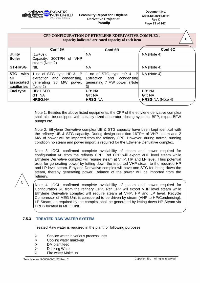
Feasibility Report for Ethylene
Derivative Project at Paradip
Document No.
A360-RP-0241-0001 Rev C
Page 93 of 147
Template No. 5-0000-0001-T2 Rev. C
Copyright EIL – All rights reserved
CPP CONFIGURATION OF ETHYLENE XDERIVATIVE COMPLEX ,
capacity indicated are rated capacity of each item
Conf 6A Conf 6B Conf 6C
Utility Boiler
(1w+0s), Capacity: 300TPH of VHP steam (Note 2)
NA NA (Note 4)
GT-HRSG NIL NA NA (Note 4)
STG with all associated auxiliaries
1 no of STG, type HP & LP extraction and condensing, generating 30 MW power. (Note 2)
1 no of STG, type HP & LP Extraction and condensing generating 7 MW power. (Note 3)
NA (Note 4)
Fuel type UB: HSFO GT: NA HRSG:NA
UB: NA GT: NA HRSG:NA
UB: NA GT: NA HRSG:NA (Note 4)
Note 1: Besides the above listed equipments, the CPP of the ethylene derivative complex shall also be equipped with suitably sized deaerator, dosing systems, BFP, export BFW pumps etc.
Note 2: Ethylene Derivative complex UB & STG capacity have been kept identical with the refinery UB & STG capacity. During design condition 16TPH of VHP steam and 2 MW of power will be imported from the refinery CPP. However, during normal running condition no steam and power import is required for the Ethylene Derivative complex. Note 3: IOCL confirmed complete availability of steam and power required for configuration 6B from the refinery CPP. Ref CPP will export VHP level steam while Ethylene Derivative complex will require steam at VHP, HP and LP level. Thus potential exist for generating power by letting down the imported VHP steam to the required HP and LP level steam. Ethylene Derivative complex will have one STG for letting down the steam, thereby generating power. Balance of the power will be imported from the refinery. Note 4: IOCL confirmed complete availability of steam and power required for Configuration 6C from the refinery CPP. Ref CPP will export VHP level steam while Ethylene Derivative complex will require steam at VHP, HP and LP level. Recycle Compressor of MEG Unit is considered to be driven by steam (VHP to HP/Condensing). LP Steam, as required by the complex shall be generated by letting down HP Steam via PRDS located in MEG Unit.
7.5.3 TREATED RAW WATER SYSTEM
Treated Raw water is required in the plant for following purposes: Service water in various process units Cooling water make-up DM plant feed Drinking Water Fire water Make up
C
C

Feasibility Report for Ethylene
Derivative Project at Paradip
Document No.
A360-RP-0241-0001 Rev C
Page 94 of 147
Template No. 5-0000-0001-T2 Rev. C
Copyright EIL – All rights reserved
Treated raw water will be received at the ethylene derivative complex battery limit at the required pressure. Raw water intake/filtering/treatment/pumping/storage facilities from source to the complex are excluded from the scope of FR.
The treated raw water shall be used for cooling water make up, DM water feed, Service water, and Drinking water and Fire water requirements through their respective pumps, located outside the ethylene derivative complex.
Treated Raw water Consumption:
The break up of the consumption of Treated raw water in the complex is as follows:
Table: 7.5.3.1: Complex Treated Raw Water requirement
Treated Raw water consumption detail
Unit
Conf 1/1A
Conf 2
Conf 3
Conf 4
Conf 5a
Conf 5b
Normal treated raw water (TRW) demand
M3/hr 600 750 1120 1110 1790 1430
Design treated raw water (TRW) demand
M3/hr 740 970 1260 1240 2010
1570
Table: 7.5.3.2: Complex Treated Raw Water requirement
Treated Raw water consumption detail
Unit
Conf 5c/e
Conf 5d
Conf 5f Conf 5g
Conf 6
Conf 6A
Conf 6B
Conf 6C
Normal treated raw water (TRW) demand
M3/hr 1090 1040 970 1370 820 870 650 670
Design treated raw water (TRW) demand
M3/hr 1220 1150 1070 1480 900 960 715 737
The treated raw water requirement has been estimated with the following assumptions: 1) Design Treated raw water numbers indicated in the table above is inclusive of 10%
Design margin considered in the individual utility systems. However Opex estimation has been carried out with normal TRW numbers.
2) RO-DM plant is envisaged. CT blow down, DM reject, boiler blow down and process effluent will be routed to RO-DM. Recovered water will be used as treated raw water. 70% recovery has been considered in RO.
3) No treated raw water reservoir has been considered inside the complex
7.5.4 DM WATER SYSTEM
DM water for the complex is required for the following purposes: - As boiler feed water make-up for the generation of steam - As process water for dilution, reaction and washing
C

Feasibility Report for Ethylene
Derivative Project at Paradip
Document No.
A360-RP-0241-0001 Rev C
Page 95 of 147
Template No. 5-0000-0001-T2 Rev. C
Copyright EIL – All rights reserved
The DM Chain shall consist of: - High rate solid contact filter (HRSC) - Dual media filter (DMF) - Activated carbon filter (ACF) - Ultra filtration (UF) - Reverse Osmosis (RO) - Mixed Bed Exchanger (MB)
The above configuration is based on the following assumptions: i) DM plant feed water quality is identical to the treated raw water quality of Paradip
Refinery.
Location of DM/CPU plant is together. The treated raw water, as supplied by IOCL, shall be used as feed for the DM plant..
Intermittent or emergency requirements of DM water will be met from the DM water storage Tank. DM water tanks shall be epoxy coated on the inside and provided with nitrogen blanketing to minimize its contact with air. The DM plant shall also consist of separate set of DM water supply pump to process units and power blocks.
The specification for the DM Water plant for different configurations are as follows:
Table: 7.5.4.1 RO-DM Water System Details
Note 1: IOCL confirmed the availability of required DM water for configuration 6A, 6B & 6C from the Paradip refinery DM plant. In view of this dedicated DM water plant has not been envisaged for these configurations in Ethylene derivative complex.
RO-DM Water System Details
Configurations Capacity of each
chain Units Number of Chains
Configuration-1/1A 180 M3/hr 1w + 1s
Configuration-2 150 M3/hr 2w + 1s
Configuration-3 225 M3/hr 2w + 1s
Configuration-4 190 M3/hr 2w + 1s
Configuration-5a 250 M3/hr 3w + 1s
Configuration-5b 230 M3/hr 2w + 1s
Configuration-5c/e 180 M3/hr 2w + 1s
Configuration-5d 160 M3/hr 2w + 1s
Configuration-5f 160 M3/hr 2w + 1s
Configuration-5g 230 M3/hr 2w + 1s
Configuration-6 170 M3/hr 1w + 1s
Configuration-6A Not required Note 1
Configuration-6B Not required Note 1
Configuration-6C Not required Note 1 C

Feasibility Report for Ethylene
Derivative Project at Paradip
Document No.
A360-RP-0241-0001 Rev C
Page 96 of 147
Template No. 5-0000-0001-T2 Rev. C
Copyright EIL – All rights reserved
7.5.5 CONDENSATE SYSTEM Condensate polishing Unit (CPU) is a centralised facility for treating suspect condensate generated in various process units. Provision to treat surface condensate and pure condensate in case of contamination is also provided. Polished condensate from CPU shall be sent to CPP de-aerator. Most of steam after getting used in turbine drives, exchangers etc gets converted to condensate, which is recovered. The pressure level of condensate generation depends on the level of steam used and the type of application. Recovered condensate after polishing for appropriate purity is sent back to CPP. Condensates of different purity are generated in process units and utility systems depending upon the application of steam. Based on possibility of contamination and type of use, condensate is classified into following: A) Pure Condensate This is condensate produced by a source where the possibility of contamination by leakage across the heat transfer surface is minimal. This is ascertained by comparing the process and steam side operating pressures for the exchanger. If the process side operating pressure is lower than the steam side operating pressure, possibility of contamination of condensate by process fluid is minimal and the condensate produced from such a source is deemed ‘pure condensate’. B) Suspect Condensate This is condensate produced by a source where the possibility of contamination by leakage across the heat transfer surface exists. This is ascertained by comparing the process and steam side operating pressures for the exchanger. If the process side operating pressure is higher than the steam side operating pressure, possibility of contamination of condensate by process fluid exists and the condensate produced from such a source is deemed ‘suspect condensate’. C) Surface Condenser Condensate This is condensate produced by the surface condenser of a condensing type steam turbine is normally considered as pure. D) Tracer/ trap Condensate Condensate produced by the tracing is suspect condensate. Condensates from following users are recoverable:
- From Steam used in heat exchangers
- From steam used in equipment heating
- From Steam tracing in unit area (ISBL). The steam used in following is unrecoverable:
- Processes like stripping, decocking, snuffing & purging
- In equipment such as Flare & Steam Ejectors
- Offsite tracing, Blow down, Deaerator vents & Evaporation losses

Feasibility Report for Ethylene
Derivative Project at Paradip
Document No.
A360-RP-0241-0001 Rev C
Page 97 of 147
Template No. 5-0000-0001-T2 Rev. C
Copyright EIL – All rights reserved
Condensate polishing unit (CPU)
The condensate polishing unit shall consist of the following:
- Feed Condensate / polished condensate exchanger
- Feed condensate trim cooler
- De-oiling unit (activated carbon filter)
- Mixed Bed exchanger Polishing unit
- Unpolished condensate storage tanks
- Unpolished condensate transfer pumps
- Polished condensate storage tanks
- Polished condensate transfer pumps
Two storage tanks for storing unpolished condensate (upstream of polisher) each equivalent to 12 hours storage shall be provided. This shall be based on total maximum suspect condensate generated from the Complex. A typical scheme of condensate polishing unit is shown below:
CPU chain CPU chain
Polished conden Storage tanks
Polished cond Transfer pump
Un Polished cond. storage tanks
Storage tanks
Feed cond. Cooler & trim cooler
Unpolished cond. pump pump

Feasibility Report for Ethylene
Derivative Project at Paradip
Document No.
A360-RP-0241-0001 Rev C
Page 98 of 147
Template No. 5-0000-0001-T2 Rev. C
Copyright EIL – All rights reserved
The specification for the Condensate Polishing Unit for different Configurations is as follows:
Table: 7.5.5.1:Condensate Polishing Unit Details
7.5.6 COMPRESSED AIR AND NITROGEN SYSTEM Compressed air is required in the complex for the following main requirements:
- As Instrument Air to operate various instruments in the facility and also for the purging of some control panels
- As Plant Air for hose stations, for regeneration of catalysts, decoking of furnaces etc.
Nitrogen is required in the complex for the following main requirements:
- Blanketing of surge drums and storage tanks - Purging of compressor seals, header purging etc. - Purging of systems during start-ups and shut-downs - Catalyst Regeneration
N2/IA/PA requirement for the complex will be met from the Compressed air and Cryogenic Nitrogen plant of the complex. Common compressors are being provided to meet both Nitrogen air requirement and Compressed air (Plant air and Instrument air) requirement of the complex. To meet the intermittent peak demands of the users, steam heated water bath vaporizer will be provided which will vaporize liquid nitrogen to meet the intermittent demands of the complex. Liquid nitrogen thus consumed will be made up from the cryogenic nitrogen plant. For storing the liquid nitrogen, atmospheric as well as pressurized storage tanks have been envisaged under the scope of this FR. The compressed air plant of the complex will comprise of the following:
Condensate Polishing Unit Details
Confs Capacity of each
chain Units Number of Chains
Conf -1/1A Not Applicable
Conf -2 Not Applicable
Conf -3 Not Applicable
Conf -4 130 M3/hr 1w + 1s
Conf -5a 100 M3/hr 2w + 1s
Conf -5b 100 M3/hr 2w + 1s
Conf -5c/e 130 M3/hr 1w + 1s
Conf -5d 130 M3/hr 1w + 1s
Conf -5f 120 M3/hr 1w + 1s
Conf -5g 100 M3/hr 2w + 1s
Conf -6 50 M3/hr 1w + 1s
Conf -6A 50 M3/hr 1w + 1s
Conf -6B 50 M3/hr 1w + 1s
Conf -6C 50 M3/hr 1w + 1s
C

Feasibility Report for Ethylene
Derivative Project at Paradip
Document No.
A360-RP-0241-0001 Rev C
Page 99 of 147
Template No. 5-0000-0001-T2 Rev. C
Copyright EIL – All rights reserved
i) LP air compressor ii) HP air compressor iii) LP and HP air receiver iv) Instrument air dryer v) Associated piping and instrumentation.
The cryogenic nitrogen plant of the complex will comprise of the following: i) Liquid nitrogen tank (atmospheric) ii) Liquid nitrogen tank (pressurized) iii) Steam heated water bath vaporizer iv) Associated piping and instrumentation.
The details of the Compressed Air & Cryogenic Nitrogen Plant for different configurations are as follows:
Table: 7.5.6.1: Compressed Air & Cryogenic Nitrogen Plant Equipment
Details Conf -1/1A Conf -2 Conf -3 Conf -4
LP Air Compressor
Capacity: 4000 Nm3/hr Quantity: 3 (2w + 1s)
Capacity: 4000 Nm3/hr Quantity: 4 (3w + 1s)
Capacity: 6000 Nm3/hr Quantity: 4 (3w + 1s)
Capacity: 5000 Nm3/hr Quantity: 3 (2w + 1s)
HP Air Compressor
Capacity: 250 Nm3/hr Quantity: 1 (1w + 0s)
Capacity: 250 Nm3/hr Quantity: 1 (1w + 0s)
Capacity: 250 Nm3/hr Quantity: 1 (1w + 0s)
Capacity: 250 Nm3/hr Quantity: 1 (1w + 0s)
Instrument Air Dryer
Capacity: 2600 Nm3/hr Quantity: 2 (1w + 1s)
Capacity: 3500 Nm3/hr Quantity: 2 (1w + 1s)
Capacity: 6000 Nm3/hr Quantity: 2 (1w + 1s)
Capacity: 3500 Nm3/hr Quantity: 2 (1w + 1s)
Cryogenic Nitrogen
Plant
Capacity: 1330 Nm3/hr
Capacity: 2000 Nm3/hr
Capacity: 4210 Nm3/hr
Capacity: 2400 Nm3/hr
Table: 7.5.6.2: Compressed Air & Cryogenic Nitrogen Plant
Equipment
Details Conf -5a Conf -5b Conf -5c/e Conf -5d
LP Air Compressor
Capacity: 8000 Nm3/hr Quantity: 4 (3w + 1s)
Capacity: 6000 Nm3/hr Quantity: 4 (3w + 1s)
Capacity: 5000 Nm3/hr Quantity: 4 (3w + 1s)
Capacity: 7000 Nm3/hr Quantity: 3 (2w + 1s)
HP Air Compressor
Capacity: 250 Nm3/hr Quantity: 1 (1w + 0s)
Capacity: 250 Nm3/hr Quantity: 1 (1w + 0s)
Capacity: 250 Nm3/hr Quantity: 1 (1w + 0s)
Capacity: 250 Nm3/hr Quantity: 1 (1w + 0s)
Instrument Air Dryer
Capacity: 4500 Nm3/hr Quantity: 3 (2w + 1s)
Capacity: 3250 Nm3/hr Quantity: 3 (2w + 1s)
Capacity: 2500 Nm3/hr Quantity: 3 (2w + 1s)
Capacity: 2500 Nm3/hr Quantity: 3 (2w + 1s)
Cryogenic Nitrogen
Plant
Capacity: 5900 Nm3/hr
Capacity: 4500 Nm3/hr
Capacity: 3300 Nm3/hr
Capacity: 3300 Nm3/hr
Table: 7.5.6.3: Compressed Air & Cryogenic Nitrogen Plant
Equipment Details
Conf -5f Conf -5g Conf -6 Conf -6A Conf -6B Conf-
6C
LP Air Compressor
Capacity: 7000 Nm3/hr Quantity: 3
(2w + 1s)
Capacity: 6000 Nm3/hr Quantity: 4
(3w + 1s)
Not required (Note1 )
Not required (Note1 )
Not required (Note1 )
HP Air Compressor
Capacity: 250 Nm3/hr Quantity: 1
(1w + 0s)
Capacity: 250 Nm3/hr Quantity: 1
(1w + 0s)
Not required (Note1)
Instrument Air Dryer
Capacity: 2500 Nm3/hr Quantity: 3
(2w + 1s)
Capacity: 3000 Nm3/hr Quantity: 3
(2w + 1s)

Feasibility Report for Ethylene
Derivative Project at Paradip
Document No.
A360-RP-0241-0001 Rev C
Page 100 of 147
Template No. 5-0000-0001-T2 Rev. C
Copyright EIL – All rights reserved
Cryogenic Nitrogen
Plant
Capacity: 3200 Nm3/hr
Capacity: 4400 Nm3/hr
Note 1: IOCL confirmed the availability of IA, PA & Nitrogen for configuration 6, 6A, 6B & 6C from the Paradip refinery compressed air and Nitrogen plant. In view of this dedicated compressed air plant and cryogenic nitrogen plant have not been envisaged for these configurations in the Ethylene Derivative complex.
7.5.7 EFFLUENT TREATMENT PLANT:
The effluent generated from the various units in various configurations, under the purview of the feasibility study, will be treated in the Effluent Treatment plant, located inside the Ethylene Derivative complex of Paradip. The effluent mainly consists of the following streams:
a) Oily water b) Waste water c) Spent DM water, etc.
7.5.8 SPENT CAUSTIC TREATMENT PLANT: A standalone Spent Caustic Treatment Plant is envisaged for the Ethylene Derivative complex of IOCL, Paradip. The spent caustic generated from the Ethylene Recovery Unit shall be treated in the Spent Caustic Treatment plant. It will be located near the Effluent treatment plant of the complex.
7.5.9 FLARE SYSTEM:
The flare system is required for safe disposal of combustible, toxic gases which, are relieved from various process plants and off sites during start-up, shutdown, normal operation or in case of an emergency such as: * Cooling water failure * Power failure * Combined cooling water and power failure * External fire * Blocked discharge * Any other operational failure
As informed by IOCL, C2 derivative complex and PP complex will share a single flare system which shall be located within PP complex. Augmentation of PP flare system will be carried out by IOCL to make it suitable for C2 derivative complex flare load as well. Hence, no plot or hardware have been allocated for the flare system of C2 derivative complex. However, cost of Flare system for Ethylene Derivative Complex have been developed for differential flare load (that is, differential of PP + C2 derivative flare load and only PP flare load) which would then be passed between Projects internally by IOCL.
C

Feasibility Report for Ethylene
Derivative Project at Paradip
Document No.
A360-RP-0241-0001 Rev C
Page 101 of 147
Template No. 5-0000-0001-T2 Rev. C
Copyright EIL – All rights reserved
SECTION 7.6
OFFSITES DESCRIPTION

Feasibility Report for Ethylene
Derivative Project at Paradip
Document No.
A360-RP-0241-0001 Rev C
Page 102 of 147
Template No. 5-0000-0001-T2 Rev. C
Copyright EIL – All rights reserved
7.6.1 OFFSITE SYSTEM FACILITIES This section gives the details of offsite system facilities required to meet the new facilities envisaged in the FR study.
The units considered under the purview of the FR are included in Section 7.1 Offsite storage facilities will include storage vessels/tanks/sphere for feed, intermediates feed, Off spec intermediate feed & products, pumping facilities, loading/unloading facilities and auxiliary facilities like boil off gas compression system, emergency vaporization/heating system/vapor recovery system etc. Besides the above, interconnecting pipelines carrying FCC off gas, Oxygen, Propylene, TRW, HSFO, RLNG, Fuel gas, Compressed off gas, EDC, VHP steam, DM water, Boiler Feed water, to/from ethylene derivative complex to refinery are also envisaged in this complex.
7.6.1.1 PRODUCT STORAGE PHILOSOPHY
The offsite storage facilities for the complex will be designed to store the products based on upstream and downstream shutdown. In general finished solid products will have storage capacity adequate enough to store 30 days unit production at 100% throughput. In general intermediate products will have storage equivalent to 5 days unit production at 100% throughput. Feed and liquid products will normally have storage capacity adequate enough to store 15 days unit production at 100% through put.
7.6.1.2 CRYOGENIC STORAGE FACILITY ETHYLENE STORAGE
7 days storage has been considered for the feed Ethylene for all the configuration other than Configuration 1 and 2. For Configuration 1 and 2 , the number of ethylene spheres has been estimated assuming 100% of the annual EVA production first followed by 100% of the annual LDPE production. For storage of ethylene for merchant sale, Double Wall Storage Tanks (DWST) shall be provided. The operating temperature and pressure of DWST are -103.6 oC and 300-700 mm WCg respectively.
For keeping the cryogenic storage, in-tank pump and feed pumps in chilled condition, during normal operation, usually a slip stream of ethylene produced (~10% of total production ) in Ethylene Recovery unit shall be run down to the storage tanks after chilling to -98°. The liquid ethylene of corresponding flow will be pumped from the DWST and pumped back to Ethylene Recovery unit to keep the line in chilled and re-circulating condition with controlled rate. In addition, the BOG generated from the tank also will be compressed and routed through the ethylene chilling train. Each tank shall have one submersible in-tank pump and a standby pump column. One pump shall be common warehouse spare. The boil off gas (BOG) generated in the storage shall be compressed and routed back to Ethylene Recovery unit for recovery.

Feasibility Report for Ethylene
Derivative Project at Paradip
Document No.
A360-RP-0241-0001 Rev C
Page 103 of 147
Template No. 5-0000-0001-T2 Rev. C
Copyright EIL – All rights reserved
For BOG estimation, one in-tank pumps, one ethylene pump have been considered to be in operation and one ethylene pump shall be under chilling. BOG generation rate shall vary depending on various factors with major contribution from run down rate. BOG load shall be maximum when run down rate is maximum. Two BOG compressors (1 operating + 1 standby) shall be considered. PROPYLENE STORAGE Liquid propylene is feed to the EPDM Unit. Liquid propylene produced in the refinery is of 93 wt% purity. Suitable offsite storage for this 93 wt% Propylene has been considered in the Refinery area. This 93 wt% propylene will then be further purified to 99.5 wt% in a PRU envisaged in the Ethylene Derivative complex. Intermediate storage for Polymer Grade Propylene has been considered in the Ethylene Derivative complex. .
7.6.1.3 PRODUCT WARE HOUSE:
The product warehouse in the Ethylene Derivative complex has been sized based on three layer basis, and for 30 days production of polymers.
7.6.1.4 OFFSITE FACILITIES SUMMARY
Following are the list of offsite facilities and their types considered for offsites storage facilities for different configurations:
Table: 7.6.1.4a: Offsite Facilities
Configuration -1
SERVICE NOMINAL
CAPACITY, M3 NUMBER OF TANKS
TYPE OF TANKS
Ethylene 2800 13 SPHERE (Note-1)
C3 product 2800 1 SPHERE
Vinyl Acetate 3200 3 CONE ROOF WITH N2
BLANKETING
Table: 7.6.1.4b: Offsite Facilities
Configuration -2
SERVICE NOMINAL
CAPACITY, M3 NUMBER OF TANKS
TYPE OF TANKS
Ethylene 2800 13 SPHERE (Note-1)
C3 product 2800 1 SPHERE
Vinyl Acetate 3200 3 CONE ROOF WITH N2
BLANKETING
ENB 170 1 IFR N2 BLANKETED
Extender oil 680 1 IFR N2 BLANKETED
Hexane 140 1 IFR N2 BLANKETED
HSFO 900 1 CONE ROOF
Propylene 950 1 SPHERE(Note-1)

Feasibility Report for Ethylene
Derivative Project at Paradip
Document No.
A360-RP-0241-0001 Rev C
Page 104 of 147
Template No. 5-0000-0001-T2 Rev. C
Copyright EIL – All rights reserved
Table: 7.6.1.4c: Offsite Facilities
Configuration -3
SERVICE NOMINAL
CAPACITY, M3 NUMBER OF TANKS
TYPE OF TANKS
Ethylene 2800 5 SPHERE (Note-1)
C3 product 2800 1 SPHERE
VCM 2800 4 SPHERE
Off Spec VCM 2800 1 SPHERE
EDC 3780
3 CONE ROOF WITH N2
BLANKETING
HSFO DELETED
Table: 7.6.1.4d: Offsite Facilities
Configuration -4
SERVICE NOMINAL
CAPACITY, M3 NUMBER OF TANKS
TYPE OF TANKS
Ethylene 2800 5 SPHERE (Note-1)
C3 product 2800 1 SPHERE
ENB 310 2 IFR N2 BLANKETED
Extender oil 1250 2 IFR N2 BLANKETED
Hexane 340 2 IFR N2 BLANKETED
Benzene feed 5780 5 IFR N2 BLANKETED
EB product 5140 3 IFR N2 BLANKETED
BT product 920 1 IFR N2 BLANKETED
Styrene Monomer
5950 6 DOME ROOF N2 BLANKETED
HSFO 1800 2 CONE ROOF
Propylene 2800 1 SPHERE(Note-1)
Table: 7.6.1.4e: Offsite Facilities
Configuration -5a
SERVICE NOMINAL
CAPACITY, M3 NUMBER
OF TANKS TYPE OF TANKS
Ethylene 2800 5 SPHERE (Note 1)
ENB 750 1 IFR N2 BLANKETED
Extender oil 1250 2 IFR N2 BLANKETED
Hexane 670 1 IFR N2 BLANKETED
C3 product 2800 1 SPHERE
Import EDC 3040 8
CONE ROOF WITH N2 BLANKETING
Intermediate EDC
3900
2 CONE ROOF WITH N2
BLANKETING
VCM 2800 5 SPHERE
Off Spec 2800 1 SPHERE

Feasibility Report for Ethylene
Derivative Project at Paradip
Document No.
A360-RP-0241-0001 Rev C
Page 105 of 147
Template No. 5-0000-0001-T2 Rev. C
Copyright EIL – All rights reserved
VCM
HSFO 1500 2 CONE ROOF
Propylene 2800 1 SPHERE(Note-1)
Table: 7.6.1.4f: Offsite Facilities
Configuration -5b
SERVICE NOMINAL
CAPACITY, M3
NUMBER OF TANKS
TYPE OF TANKS
Ethylene 2800 4 SPHERE (Note 1)
C3 product 2800 1 SPHERE
Import EDC 3040
8 CONE ROOF WITH N2
BLANKETING
Intermediate EDC 3900 2 CONE ROOF WITH N2
BLANKETING
VCM 2800 5 SPHERE
Off Spec VCM 2800 1 SPHERE
HSFO 1750 1 CONE ROOF
Ethylene 21600 1 DOUBLE WALL STORAGE
TANK (Note 2)
Table: 7.6.1.4g: Offsite Facilities
Configuration -5c/e
SERVICE NOMINAL CAPACITY,
M3
NUMBER OF TANKS
TYPE OF TANKS
Ethylene 2800 3 SPHERE (Note-1)
C3 product 2800 1 SPHERE
Import EDC 2700 6 CONE ROOF WITH N2
BLANKETING
Intermediate EDC 2630
2 CONE ROOF WITH N2
BLANKETING
VCM 2800 4 SPHERE
Off Spec VCM 2800 1 SPHERE
HSFO 1000 2 CONE ROOF
Ethylene 21600 1 DOUBLE WALL STORAGE
TANK (Note 2)
Table: 7.6.1.4h: Offsite Facilities
Configuration -5d
SERVICE NOMINAL
CAPACITY, M3
NUMBER OF TANKS
TYPE OF TANKS
Ethylene 2800 3 SPHERE (Note-1)
C3 product 2800 1 SPHERE
Import EDC 2700 6 CONE ROOF WITH N2

Feasibility Report for Ethylene
Derivative Project at Paradip
Document No.
A360-RP-0241-0001 Rev C
Page 106 of 147
Template No. 5-0000-0001-T2 Rev. C
Copyright EIL – All rights reserved
BLANKETING
Intermediate EDC
2630
2 CONE ROOF WITH N2
BLANKETING
VCM 2800 4 SPHERE
Off Spec VCM 2800 1 SPHERE
HSFO 1000 2 CONE ROOF
Ethylene 21600 1 DOUBLE WALL STORAGE
TANK (Note 2)
Table: 7.6.1.4i: Offsite Facilities
Configuration -5f
SERVICE NOMINAL CAPACITY,
M3
NUMBER OF TANKS
TYPE OF TANKS
Ethylene 2800 3 SPHERE (Note-1)
C3 product 2800 1 SPHERE
Import EDC 2700 6 CONE ROOF WITH N2
BLANKETING
Intermediate EDC 2630
2 CONE ROOF WITH N2
BLANKETING
VCM 2800 4 SPHERE
Off Spec VCM 2800 1 SPHERE
HSFO 1150 1 CONE ROOF
Table: 7.6.1.4j: Offsite Facilities
Configuration -5g
SERVICE NOMINAL CAPACITY,
M3
NUMBER OF TANKS
TYPE OF TANKS
Ethylene 2800 4 SPHERE (Note 1)
C3 product 2800 1 SPHERE
Import EDC 3040 8 CONE ROOF WITH N2
BLANKETING
Intermediate EDC
3900 2 CONE ROOF WITH N2
BLANKETING
VCM 2800 5 SPHERE
Off Spec VCM 2800 1 SPHERE
HSFO 1200 1 CONE ROOF
Table: 7.6.1.4k: Offsite Facilities
Configuration -6
SERVICE NOMINAL
CAPACITY, M3
NUMBER OF TANKS
TYPE OF TANKS
Ethylene 2800 5 SPHERE (Note-1)
C3 product 2800 1 SPHERE
MEG 4800 4 FIXED ROOF WITH N2

Feasibility Report for Ethylene
Derivative Project at Paradip
Document No.
A360-RP-0241-0001 Rev C
Page 107 of 147
Template No. 5-0000-0001-T2 Rev. C
Copyright EIL – All rights reserved
BLANKETING
DEG 1350 1 FIXED ROOF WITH N2
BLANKETING
TEG 70 1 FIXED ROOF WITH N2
BLANKETING
HSFO 1500 1 CONE ROOF
Table: 7.6.1.4l: Offsite Facilities Configuration -6A
SERVICE NOMINAL
CAPACITY, M3
NUMBER OF TANKS
TYPE OF TANKS
Ethylene 2800 5 SPHERE (Note-1)
C3 product 2800 1 SPHERE
MEG 4800 4 FIXED ROOF WITH N2
BLANKETING
DEG 1350 1 FIXED ROOF WITH N2
BLANKETING
TEG 70 1 FIXED ROOF WITH N2
BLANKETING
HSFO 1800 2 CONE ROOF
Table: 7.6.1.4m: Offsite Facilities
Configuration -6B
SERVICE NOMINAL
CAPACITY, M3
NUMBER OF TANKS
TYPE OF TANKS
Ethylene 2800 5 SPHERE (Note-1)
C3 product 2800 1 SPHERE
MEG 4800 4 FIXED ROOF WITH N2
BLANKETING
DEG 1350 1 FIXED ROOF WITH N2
BLANKETING
TEG 70 1 FIXED ROOF WITH N2
BLANKETING

Feasibility Report for Ethylene
Derivative Project at Paradip
Document No.
A360-RP-0241-0001 Rev C
Page 108 of 147
Template No. 5-0000-0001-T2 Rev. C
Copyright EIL – All rights reserved
Table: 7.6.1.4 n: Offsite Facilities Configuration -6C
SERVICE NOMINAL
CAPACITY, M3
NUMBER OF TANKS
TYPE OF TANKS
Ethylene 2800 5 SPHERE (Note-1)
C3 product 2800 1 SPHERE
MEG 4800 4 FIXED ROOF WITH N2
BLANKETING
DEG 1350 1 FIXED ROOF WITH N2
BLANKETING
TEG 70 1 FIXED ROOF WITH N2
BLANKETING
Note 1: Ethylene / Propylene spheres to be provided with liquid ethylene / liquid propylene vaporiser. Note 2: Ethylene DWST is to be provided with other accessories as listed below:
a) Ethylene in-tank pump (1+1), b) MP ethylene pumps (1+1), c) MP ethylene emergency vaporiser with MP ethylene desuperheater, d) Ethylene BOG compressor suction KOD, e) Ethylene BOG compressors (1+1).
7.6.1.5 INTERCONNECTING PIPELINES SUMMARY Following are the list of interconnecting pipelines and their specification considered for all the configuration of the Ethylene Derivative complex.
Table: 7.6.1.5a: Interconnecting Pipelines Summary
Service Configuration
1 Configuration
2 Configuration
3 Configuration
4 Configuration
5a
FCC off gas
Size=28", MOC=CS,
CA=1.5 mm, Rating=150#, St
length=6 KM
Size=28", MOC=CS,
CA=1.5 mm, Rating=150#, St
length=6 KM
Size=28", MOC=CS,
CA=1.5 mm, Rating=150#, St
length=6 KM
Size=28", MOC=CS,
CA=1.5 mm, Rating=150#, St
length=6 KM
Size=28", MOC=CS,
CA=1.5 mm, Rating=150#, St
length=6 KM
Propylene NA
Size=3", MOC=CS,
CA=1.5 mm, Rating=300#, St length=5.3 KM NA
Size=4", MOC=CS,
CA=1.5 mm, Rating=300#, St length=5.3 KM
Size=6", MOC=CS,
CA=1.5 mm, Rating=300#, St length=5.3 KM
C

Feasibility Report for Ethylene
Derivative Project at Paradip
Document No.
A360-RP-0241-0001 Rev C
Page 109 of 147
Template No. 5-0000-0001-T2 Rev. C
Copyright EIL – All rights reserved
Oxygen NA NA
Size=10", MOC=SS 304L,
CA=0 mm, Rating=150#, St
length=6 KM NA
Size=12", MOC=SS 304L,
CA=0 mm, Rating=150#, St
length=6 KM
HSFO NA
Size=6", MOC=CS,
CA=1.5 mm, Rating=300#, St length=7.5 KM NA
Size=6", MOC=CS,
CA=1.5 mm, Rating=300#, St length=7.5 KM
Size=6", MOC=CS,
CA=1.5 mm, Rating=300#, St length=7.5 KM
RLNG
Size=6", MOC=CS,
CA=1.5 mm, Rating=300#, St
length=6 KM
Size=6", MOC=CS,
CA=1.5 mm, Rating=300#, St
length=6 KM
Size=8", MOC=CS,
CA=1.5 mm, Rating=300#, St
length=6 KM
Size=6", MOC=CS,
CA=1.5 mm, Rating=300#, St
length=6 KM
Size=6", MOC=CS,
CA=1.5 mm, Rating=300#, St
length=6 KM
Treated Raw water
Size=26", MOC=CS,
CA=1.5 mm, Rating=150#, St length=7.5 KM
Size=26", MOC=CS,
CA=1.5 mm, Rating=150#, St length=7.5 KM
Size=30", MOC=CS,
CA=1.5 mm, Rating=150#, St length=7.5 KM
Size=30", MOC=CS,
CA=1.5 mm, Rating=150#, St length=7.5 KM
Size=36", MOC=CS,
CA=1.5 mm, Rating=150#, St length=7.5 KM
Fuel gas Size=24", MOC=CS,
CA=1.5 mm, Rating=150#, St
length=6 KM
Size=24", MOC=CS,
CA=1.5 mm, Rating=150#, St
length=6 KM
Size=24", MOC=CS,
CA=1.5 mm, Rating=150#, St
length=6 KM
Size=24", MOC=CS,
CA=1.5 mm, Rating=150#, St
length=6 KM
Size=24", MOC=CS,
CA=1.5 mm, Rating=150#, St
length=6 KM
Compressed off gas NA NA NA
Size=8", MOC=CS (H2
service), CA=1.5 mm,
Rating=300#, St length=6 KM NA
VHP steam (Note 3)
Size=24", MOC=2.25 Cr +
1.0 Mo, CA=1.5 mm,
Rating=2500#, IBR service , St length=4.5
KM
Size=24", MOC=2.25 Cr +
1.0 Mo, CA=1.5 mm,
Rating=2500#, IBR service , St length=4.5
KM
Size=24", MOC=2.25 Cr +
1.0 Mo, CA=1.5 mm,
Rating=2500#, IBR service,
St length=4.5 KM
Size=24", MOC=2.25 Cr +
1.0 Mo, CA=1.5 mm,
Rating=2500#, IBR service , St length=4.5
KM
Size=24", MOC=2.25 Cr +
1.0 Mo, CA=1.5 mm,
Rating=2500#, IBR service , St length=4.5
KM
EDC NA NA NA NA
Size=12", MOC=CS,
CA=1.5 mm, Rating=150#,
St length=20.0 KM
Also include EDC unloading arms at Jetty
B

Feasibility Report for Ethylene
Derivative Project at Paradip
Document No.
A360-RP-0241-0001 Rev C
Page 110 of 147
Template No. 5-0000-0001-T2 Rev. C
Copyright EIL – All rights reserved
Table: 7.6.1.5b: Interconnecting Pipelines Summary
Service Configuration
5b Configuration
5c/5e Configuration
5d Configuration
5f
FCC off gas
Size=28", MOC=CS,
CA=1.5 mm, Rating=150#, St
length=6 KM
Size=28", MOC=CS,
CA=1.5 mm, Rating=150#, St
length=6 KM
Size=26", MOC=CS,
CA=1.5 mm, Rating=150#, St
length=6 KM
Size=24", MOC=CS,
CA=1.5 mm, Rating=150#, St
length=6 KM
Oxygen
Size=12", MOC=SS 304L,
CA=0 mm, Rating=150#, St
length=6 KM
Size=10", MOC=SS 304L,
CA=0 mm, Rating=150#, St
length=6 KM
Size=10", MOC=SS 304L,
CA=0 mm, Rating=150#, St
length=6 KM
Size=10", MOC=SS 304L,
CA=0 mm, Rating=150#, St
length=6 KM
HSFO
Size=6", MOC=CS,
CA=1.5 mm, Rating=300#, St length=7.5 KM
Size=6", MOC=CS,
CA=1.5 mm, Rating=300#, St length=7.5 KM
Size=6", MOC=CS,
CA=1.5 mm, Rating=300#, St length=7.5 KM
Size=6", MOC=CS,
CA=1.5 mm, Rating=300#, St length=7.5 KM
RLNG
Size=6", MOC=CS,
CA=1.5 mm, Rating=300#, St
length=6 KM
Size=6", MOC=CS,
CA=1.5 mm, Rating=300#, St
length=6 KM
Size=6", MOC=CS,
CA=1.5 mm, Rating=300#, St
length=6 KM
Size=6", MOC=CS,
CA=1.5 mm, Rating=300#, St
length=6 KM
Treated Raw water
Size=32", MOC=CS,
CA=1.5 mm, Rating=150#, St length=7.5 KM
Size=30", MOC=CS,
CA=1.5 mm, Rating=150#, St length=7.5 KM
Size=30", MOC=CS,
CA=1.5 mm, Rating=150#, St length=7.5 KM
Size=30", MOC=CS,
CA=1.5 mm, Rating=150#, St length=7.5 KM
Fuel gas
Size=24", MOC=CS,
CA=1.5 mm, Rating=150#, St
length=6 KM
Size=24", MOC=CS,
CA=1.5 mm, Rating=150#, St
length=6 KM
Size=24", MOC=CS,
CA=1.5 mm, Rating=150#, St
length=6 KM
Size=18", MOC=CS,
CA=1.5 mm, Rating=150#, St
length=6 KM
VHP steam (Note 3)
Size=24", MOC=2.25 Cr +
1.0 Mo, CA=1.5 mm,
Rating=2500#, IBR service , St length=4.5
KM
Size=24", MOC=2.25 Cr +
1.0 Mo, CA=1.5 mm,
Rating=2500#, IBR service , St length=4.5
KM
Size=24", MOC=2.25 Cr +
1.0 Mo, CA=1.5 mm,
Rating=2500#, IBR service , St length=4.5
KM
Size=24", MOC=2.25 Cr +
1.0 Mo, CA=1.5 mm,
Rating=2500#, IBR service , St length=4.5
KM
EDC Size=12", MOC=CS,
CA=1.5 mm, Rating=150#,
St length=20.0 KM
Also include
Size=12", MOC=CS,
CA=1.5 mm, Rating=150#,
St length=20.0 KM
Also include
Size=12", MOC=CS,
CA=1.5 mm, Rating=150#,
St length=20.0 KM
Also include
Size=12", MOC=CS,
CA=1.5 mm, Rating=150#,
St length=20.0 KM
Also include
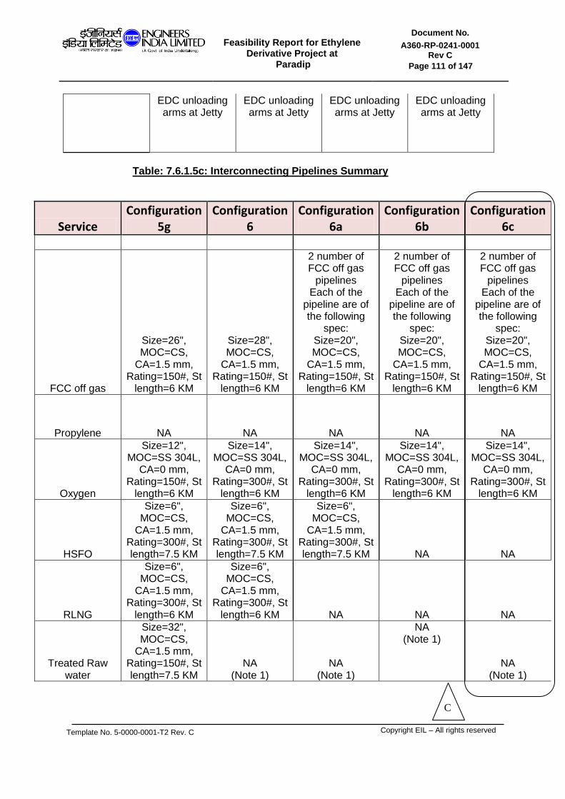
Feasibility Report for Ethylene
Derivative Project at Paradip
Document No.
A360-RP-0241-0001 Rev C
Page 111 of 147
Template No. 5-0000-0001-T2 Rev. C
Copyright EIL – All rights reserved
EDC unloading arms at Jetty
EDC unloading arms at Jetty
EDC unloading arms at Jetty
EDC unloading arms at Jetty
Table: 7.6.1.5c: Interconnecting Pipelines Summary
Service Configuration
5g Configuration
6 Configuration
6a Configuration
6b Configuration
6c
FCC off gas
Size=26", MOC=CS,
CA=1.5 mm, Rating=150#, St
length=6 KM
Size=28", MOC=CS,
CA=1.5 mm, Rating=150#, St
length=6 KM
2 number of FCC off gas
pipelines Each of the
pipeline are of the following
spec: Size=20", MOC=CS,
CA=1.5 mm, Rating=150#, St
length=6 KM
2 number of FCC off gas
pipelines Each of the
pipeline are of the following
spec: Size=20", MOC=CS,
CA=1.5 mm, Rating=150#, St
length=6 KM
2 number of FCC off gas
pipelines Each of the
pipeline are of the following
spec: Size=20", MOC=CS,
CA=1.5 mm, Rating=150#, St
length=6 KM
Propylene NA NA NA NA NA
Oxygen
Size=12", MOC=SS 304L,
CA=0 mm, Rating=150#, St
length=6 KM
Size=14", MOC=SS 304L,
CA=0 mm, Rating=300#, St
length=6 KM
Size=14", MOC=SS 304L,
CA=0 mm, Rating=300#, St
length=6 KM
Size=14", MOC=SS 304L,
CA=0 mm, Rating=300#, St
length=6 KM
Size=14", MOC=SS 304L,
CA=0 mm, Rating=300#, St
length=6 KM
HSFO
Size=6", MOC=CS,
CA=1.5 mm, Rating=300#, St length=7.5 KM
Size=6", MOC=CS,
CA=1.5 mm, Rating=300#, St length=7.5 KM
Size=6", MOC=CS,
CA=1.5 mm, Rating=300#, St length=7.5 KM NA NA
RLNG
Size=6", MOC=CS,
CA=1.5 mm, Rating=300#, St
length=6 KM
Size=6", MOC=CS,
CA=1.5 mm, Rating=300#, St
length=6 KM NA NA NA
Treated Raw water
Size=32", MOC=CS,
CA=1.5 mm, Rating=150#, St length=7.5 KM
NA (Note 1)
NA (Note 1)
NA (Note 1)
NA (Note 1)
C

Feasibility Report for Ethylene
Derivative Project at Paradip
Document No.
A360-RP-0241-0001 Rev C
Page 112 of 147
Template No. 5-0000-0001-T2 Rev. C
Copyright EIL – All rights reserved
Fuel gas
Size=24", MOC=CS,
CA=1.5 mm, Rating=150#, St
length=6 KM NA
(Note 2) NA
(Note 2) NA
(Note 2)
NA (Note 2)
VHP steam (Note 3)
Size=24", MOC=2.25 Cr +
1.0 Mo, CA=1.5 mm,
Rating=2500#, IBR service , St length=4.5
KM
Size=24", MOC=2.25 Cr +
1.0 Mo, CA=1.5 mm,
Rating=2500#, IBR service , St length=4.5
KM
Size=24", MOC=2.25 Cr +
1.0 Mo, CA=1.5 mm,
Rating=2500#, IBR service , St length=4.5
KM
Size=24", MOC=2.25 Cr +
1.0 Mo, CA=1.5 mm,
Rating=2500#, IBR service , St length=4.5
KM
Size=24", MOC=2.25 Cr +
1.0 Mo, CA=1.5 mm,
Rating=2500#, IBR service , St length=4.5
KM
EDC
Size=12", MOC=CS,
CA=1.5 mm, Rating=150#,
St length=20.0 KM
Also include EDC unloading arms at Jetty NA NA NA NA
DM water line NA NA
Size=12", MOC=SS 304,
CA=0 mm, Rating=150#, St length=4.5
KM
Size=10", MOC=SS 304,
CA=0 mm, Rating=150#, St length=4.5
KM
Size=10", MOC=SS 304,
CA=0 mm, Rating=150#, St length=4.5
KM
Boiler Feed Water NA NA NA
Size=4", MOC=Carbon
steel, IBR service
CA=1.5 mm, Rating=300#, St length=4.5
KM
Size=4", MOC=Carbon
steel, IBR service
CA=1.5 mm, Rating=300#, St length=4.5
KM
Power cable NA NA
Power import=30 MW, Voltage level of
power transmission=
66 KV Run length of power cable=
4.5 Km
Power import=30 MW, Voltage level of
power transmission=
66 KV Run length of power cable=
4.5 Km
Power import=20 MW, Voltage level of
power transmission=
66 KV Run length of power cable=
4.5 Km
Note 1: IOCL confirmed that no separate pipeline to be considered for TRW for Configuration 6/6A/6B/6C as the TRW pipeline envisaged for the PP complex can accommodate the additional TRW requirement for the ethylene derivative complex.
C

Feasibility Report for Ethylene
Derivative Project at Paradip
Document No.
A360-RP-0241-0001 Rev C
Page 113 of 147
Template No. 5-0000-0001-T2 Rev. C
Copyright EIL – All rights reserved
Note 2: IOCL also confirmed that no separate pipeline to be considered for Fuel gas for Configuration 6/6A/6B/6C as the Fuel gas pipeline envisaged for the PP complex can accommodate the additional Fuel gas generation for the ethylene derivative complex. Note 3: VHP steam flow is zero for all the configuration except for Configuration 6B.

Feasibility Report for Ethylene
Derivative Project at Paradip
Document No.
A360-RP-0241-0001 Rev C
Page 114 of 147
Template No. 5-0000-0001-T2 Rev. C
Copyright EIL – All rights reserved
SECTION 7.7
LOGISTICS

Feasibility Report for Ethylene
Derivative Project at Paradip
Document No.
A360-RP-0241-0001 Rev C
Page 115 of 147
Template No. 5-0000-0001-T2 Rev. C
Copyright EIL – All rights reserved
Mode of transport for various feed, products and internal streams of the ethylene derivative complex are as listed below in Table 7.7.1.
Table: 7.7.1: Despatch mode for Feeds, Products and internal streams.
Sl No.
Item Phase Mode of transfer Outside C2 complex B/L
Point of termination / Point of Pickup
Product
1 EVA / LDPE Solid ROAD C2 complex B/L
2 EPDM- Solid ROAD C2 complex B/L
3 PVC Solid ROAD C2 complex B/L
4 Caustic Liquid ROAD C2 complex B/L
5 SM Liquid ROAD C2 complex B/L
6 BT By product
Liquid ROAD C2 complex B/L
7 MEG/ DEG/ TEG
Liquid ROAD C2 complex B/L
8 Ethylene Liquid SHIP C2 complex B/L (Note 1,3)
Feed
1 EDC Liquid SHIP C2 complex B/L (Note 1,2)
2 Benzene Liquid ROAD C2 complex B/L
3 VAM Liquid ROAD C2 complex B/L
4 Salt Solid ROAD C2 complex B/L
5 Chlorine Liquid ROAD C2 complex B/L
5 Cat / chem. / additives ( e.g ENB , extender oil )
Solid / Liquid
ROAD C2 complex B/L
Streams to / from Refinery
1 Propylene Liquid Pipeline transfer between Paradip Refinery and C2 derivative complex has been considered up to Battery Limit of the C2 Derivative Complex
2 FCC gas Gas
3 Oxygen Gas
4 TRW Liquid
5 HSFO , RLNG ,
Liquid , Gas
6 Fuel Gas export , C2 purge export
Gas
Note 1 As confirmed by IOCL, new chemical jetty cost is not to be considered for Ethylene export and EDC import. Note 2 As confirmed by IOCL , for EDC import, unloading arms and unloading line from Jetty to Paradip Refinery is not to be considered. Also shore tanks is not to be considered. EDC storage is to be considered within C2 Derivative Complex. Note 3 As confirmed by IOCL , for ethylene export, additional loading arms & loading lines from Paradip refinery to Jetty is not to be considered. There would be spare propylene loading arms & loading lines available which would be modified by IOCL for ethylene use. Ethylene storage is

Feasibility Report for Ethylene
Derivative Project at Paradip
Document No.
A360-RP-0241-0001 Rev C
Page 116 of 147
Template No. 5-0000-0001-T2 Rev. C
Copyright EIL – All rights reserved
not to be considered at the port. All ethylene storage are to be considered within C2 Derivative Complex.
7.7.1 There is a creek separating the refinery and petrochemical complex. A road cum Pipe Bridge is under construction for laying the necessary pipelines for crossing the creek. The new Ethylene derivative complex will be located in the north side of the creek. Adequacy check of the upcoming bridge for laying the feed, Product lines and utility lines across the creek to be undertaken for the chosen configuration. However as confirmed by IOCL, for chosen configuration., it can be assumed that enough empty sleeves are available in the pipe bridge and thus no separate cost towards new pipe bridge is to be considered in this FR study.
7.7.2 The following section deals with the movement of raw material, utilities and finished products for Configuration 6C of the Ethylene derivative complex.
7.7.2.1 RAW MATERIAL
1. Ethylene FCC off gas from Refinery FCC will be routed via pipeline to Ethylene Recovery Unit, located in the Ethylene Derivative Complex. Polymer grade ethylene will be recovered in ERU. This PG Ethylene will then be used as feed for the MEG unit. For the proposed Ethylene Derivative complex, 220 KTPA of Polymer grade Ethylene (99.9 mole % ethylene content) is to be made available. Five no. of sphere of capacity 2800 m3 each have been considered for storing PG ethylene for Configuration 6C of the C2 derivative complex.
2. Propylene
Propylene is required as Binary Refrigerant in ERU. As confirmed by ERU Licensor, 93 wt% Propylene, as available from the Refinery PRU, is suitable for use in ERU. Suitable offsite storage for this 93 wt% Propylene has been considered in the Refinery area. Hence no additional propylene storage has been envisaged for Configuration 6C in the Ethylene derivative complex.
3. Oxygen Oxygen is used as feed for the MEG unit of Configuration 6C. 229 KTPA of Oxygen is required by MEG unit for generating 372 KTPA of MEG product. Oxygen will be made available at Ethylene derivative battery limit from the refinery area and will reach the C2 complex via pipeline. No separate oxygen storage has been considered in the Ethylene derivative complex.
7.7.2.2 UTILITIES
As confirmed by IOCL, following utilities as required for Conf 6C will be made available from the existing Refinery: a) VHP steam (Refinery to C2 complex) b) Power (Refinery to C2 complex)
C

Feasibility Report for Ethylene
Derivative Project at Paradip
Document No.
A360-RP-0241-0001 Rev C
Page 117 of 147
Template No. 5-0000-0001-T2 Rev. C
Copyright EIL – All rights reserved
c) DM water (Refinery to C2 complex) d) Boiler Feed Water (Refinery to C2 complex) e) Treated Raw Water (Refinery to C2 complex) f) Condensate (C2 complex to Refinery) g) Effluent (C2 complex to Refinery)
Separate pipeline, crossing the creek, have been considered for transporting VHP steam, DM water and Boiler feed water from Refinery to C2 complex. Balance of utility, as confirmed by IOCL, will be transported through pipelines already envisaged for the PP project.
7.7.2.3 FINISHED PRODUCTS
1. MEG It is the final finished product from the MEG unit and shall be dispatched through road containers. 372000 TPA production of MEG is expected from the plant. Dedicated loading facility along with product tankages has been considered in offsite area. Four no. of Fixed Roof with N2 blanketing type tanks of capacity 4800 m3 each for MEG storage is considered for Configuration 6C of the Ethylene derivative complex.
2. DEG
DEG is also one of the final finished products from the MEG unit and shall be dispatched through road containers. 27000 TPA production of DEG is expected from the plant. Dedicated loading facility along with product tankages has been considered in offsite area. One no of Fixed Roof with N2 blanketing type tank of capacity 1350 m3 each for DEG storage is considered for Configuration 6C of the Ethylene derivative complex.
3. TEG
TEG is also one of the final finished products from the MEG unit and shall be dispatched through road containers. 2000 TPA production of TEG is expected from the plant. Dedicated loading facility along with product tankages has been considered in offsite area. One Fixed Roof with N2 blanketing type tank of capacity 70 m3 each for TEG storage is considered for Configuration 6C of the Ethylene derivative complex.
7.7.3 ROAD LOADING AND UNLOADING GANTRY AT TANK FARM Gantries will be used for road loading of finished liquid products. Top loading of the tanker is considered for non pressurized filling and bottom loading is considered for pressurized filling. One shift of eight hours is considered for loading and unloading operation in a day. Effective loading time for non- pressurized filling of one tanker is 30 minutes and connection/disconnection time is 45 minutes. However, loading operations in each shift has been considered for maximum of 4 hrs to calculate the number of bays. Maximum loading rate considered for non pressurized filling is 48 m3/hr. Capacity of the road tanker is considered as 20 m3 for arriving at number of bays. Number of bays is decided considering dedicated bay for individual products.
C

Feasibility Report for Ethylene
Derivative Project at Paradip
Document No.
A360-RP-0241-0001 Rev C
Page 118 of 147
Template No. 5-0000-0001-T2 Rev. C
Copyright EIL – All rights reserved
Tanker loading shall be considered for the finished products only. Loading bays for Configuration-6C have been listed below:
Service Volume handled per day, m3
Maximum filling time available per
day, hr
No of loading bays
Capacity of each bay
MEG 1024 4 8 + 1 48 m3/hr
DEG 74 4 1 + 1 48 m3/hr
TEG 6 4 1 + 1 48 m3/hr
In the Storage, Handling and transfer facilities, liquid effluent is generated from tank / pump draining and cleaning during maintenance periods and from thermal safety valve discharges. The disposal system shall be as follows:
Effluent generated from the tankages, pump station and loading area will be routed to Refinery ETP for treatment.
C
Feasibility Report for Ethylene
Derivative Project at Paradip
Document No.
A360-RP-0241-0001 Rev C
Page 119 of 147
Template No. 5-0000-0001-T2 Rev. C
Copyright EIL – All rights reserved
SECTION 8.0
ENVIRONMENTAL CONSIDERATION

Feasibility Report for Ethylene
Derivative Project at Paradip
Document No.
A360-RP-0241-0001 Rev C
Page 120 of 147
Template No. 5-0000-0001-T2 Rev. C
Copyright EIL – All rights reserved
8.1 INTRODUCTION
Industrial development is essential for growth and betterment of the living conditions of the society. Industrial development, however, is endemic with its effect on the environment. It is essential that even while the industrial development is spurred for growth, the environment is conserved and protected. The proposed Expansion of Petrochemical Complex Project is a step in the direction of spurring industrial activity. Notwithstanding this fact, it has been considered essential to adopt environmental protection measures and adhere to legislations such that the ecology and the habitat of the area are not disturbed.
Various pollution control measures required to meet the prevailing environmental standards are planned at the different stages of execution of the project, viz., design, construction and operational phases.
8.2 EFFLUENT SUMMARY
Effluent in the form of Liquid, Gas and solid phases will be generated from process units and other associated areas in this project. The liquid, solid, gaseous emission from the various configuration of the proposed ethylene derivative complex is tabulated below. This effluent summary does not include flue gas from utility boilers/HRSGs.
Table 8.2.1: Effluent Summary
Configuration 1 / 1a
Unit Liquid effluent Rate UOM Destination Stream
specification
ERU Spent caustic 710.1 kg/hr WWTP
90 wt% water, 1.3 wt% NaOH, 5.4 wt% Na2CO3, 3.3 % of Na2S, pH 12-14.
Oily water 2147.4 kg/hr WWTP
Phenols <1 mg/kg , BOD <0.03 mg/l,
COD <0.05 mg/l , Ph 7-9
EVA LDPE
Oily water sewer 0-30 m3/h WWTP HC phase to be
incinerated and water to be sent to WWTP
Pellet water sewer 2 to 36 m3/h WWTP
Slop oil 20 to 100 kg/h WWTP
Initiator waste 6.0 m3/month WWTP
Unit Solid effluent Rate UOM Destination Stream
specification
EPDM waste crumb 0.2 TPH INCINERATOR / SALE
activated alumina 42.7 TPA

Feasibility Report for Ethylene
Derivative Project at Paradip
Document No.
A360-RP-0241-0001 Rev C
Page 121 of 147
Template No. 5-0000-0001-T2 Rev. C
Copyright EIL – All rights reserved
Table 8.2.2 Effluent Summary
Configuration 2
Unit Liquid effluent Rate UOM Destination Stream
specification
ERU Spent caustic 710.1 kg/hr WWTP
90 wt% water, 1.3 wt% NaOH, 5.4 wt% Na2CO3, 3.3 % of Na2S, pH 12-14.
Oily water 2147.4 kg/hr WWTP
Phenols <1 mg/kg , BOD <0.03 mg/l, COD
<0.05 mg/l , Ph 7-9
EVA LDPE
Oily water sewer 0-30 m3/h WWTP HC phase to be incinerated and water to be sent to WWTP
Pellet water sewer 2 to 36 m3/h WWTP
Slop oil 20 to 100 kg/h WWTP
Initiator waste 6.0 m3/month WWTP
EPDM Waste water 93.3 TPH WWTP
COD=120 (nor) mg/l, 200 (max) mg/l, pH=7
Unit Solid effluent Rate UOM Destination Stream
specification
EPDM waste crumb 0.2 TPH INCINERATOR /
SALE
activated alumina 42.7 TPA
Table 8.2.3 Effluent Summary
Configuration 3
Unit Liquid effluent Rate UOM Destination Stream specification
ERU Spent caustic 710.1 kg/hr WWTP
90 wt% water, 1.3 wt% NaOH, 5.4 wt%
Na2CO3, 3.3 % of Na2S, pH 12-14.
Oily water 2147.4 kg/hr WWTP
Phenols <1 mg/kg , BOD <0.03 mg/l, COD <0.05
mg/l , Ph 7-9
EDC/VCM Waste water 20737.5 kg/hr WWTP H20 with 800 PPM BOD
and 1100 PPM COD
PVC Waste water 141800.0 kg/hr WWTP
PH=7, BOD=max 100 mg/l, COD=max 600
mg/l, VCM=max 1 ppm, PVC=max 350 mg/l
Unit Solid effluent Rate UOM Destination Stream specification
PVC Waste PVC 87.5 kg/hr SALE
Unit Gaseous effluent Rate UOM Destination Stream specification
EDC/VCM
Vent 3337.5 kg/hr Incinerator
80.6% N2, 5.5% O2, 5.6% HCl, 2.3% NCH,
2.7% CO/CO2, 3.3% CH
Light ends 862.5 kg/hr Incinerator 72.6% Chlorine, 24.2 % Carbon, 3.1 % Hydrogen
Heavy ends 1237.5 kg/hr Incinerator 72.6% Chlorine, 24.2 % Carbon, 3.1 % Hydrogen

Feasibility Report for Ethylene
Derivative Project at Paradip
Document No.
A360-RP-0241-0001 Rev C
Page 122 of 147
Template No. 5-0000-0001-T2 Rev. C
Copyright EIL – All rights reserved
PVC Vent to VCM plant 375.0 kg/hr Incinerator
Nitrogen with 20 ppm VCM max on volume
basis
Table 8.2.4 Effluent Summary
Configuration 4
Unit Liquid effluent Rate UOM Destination Stream specification
ERU Spent caustic 710.1 kg/hr WWTP
90 wt% water, 1.3 wt% NaOH, 5.4 wt% Na2CO3, 3.3 % of Na2S, pH 12-14.
Oily water 2147.4 kg/hr WWTP
Phenols <1 mg/kg , BOD <0.03 mg/l, COD <0.05
mg/l , Ph 7-9
EB/SM Storm water 3114.1 kg/hr WWTP COD=120 (nor) mg/l, 200
(max) mg/l, pH=7
EPDM Waste water 151.2 TPH WWTP
PH=7, BOD=max 100 mg/l, COD=max 600 mg/l,
VCM=max 1 ppm, PVC=max 350 mg/l
Unit Solid effluent Rate UOM Destination Stream specification
EPDM waste crumb 0.2 TPH Incinerator / Sale
activated alumina 69.1 TPA
Table 8.2.5 Effluent Summary
Configuration 5a
Unit Liquid effluent Rate UOM Destination Stream specification
ERU Spent caustic 710.1 kg/hr WWTP
90 wt% water, 1.3 wt% NaOH, 5.4 wt%
Na2CO3, 3.3 % of Na2S, pH 12-14.
Oily water 2147.4 kg/hr WWTP
Phenols <1 mg/kg , BOD <0.03 mg/l, COD
<0.05 mg/l , Ph 7-9
EDC/VCM Waste water 0.0 kg/hr WWTP
PVC Waste water 189.0 m3/hr WWTP
PH=7 to 8.5, BOD=max 200 mg/l, COD=max
200 mg/l, VCM=max 1 ppm, PVC=approx 200
mg/l
Spent DM water 210.0 m3/hr WWTP (max spent DM
water=375 m3/hr)
EPDM Waste water 212.8 t/h WWTP
Unit Solid effluent Rate UOM Destination Stream specification
PVC Waste PVC minimal kg/hr SALE
EPDM activated alumina 97.3 t/y Landfill
Unit Gaseous effluent Rate UOM Destination Stream specification
PVC Vent to VCM plant 57.0 Nm3/hr Incinerator (VCM approx 35%, inert
gas 65%)
EPDM exhaust Air 169600.0 nm3/h RTO

Feasibility Report for Ethylene
Derivative Project at Paradip
Document No.
A360-RP-0241-0001 Rev C
Page 123 of 147
Template No. 5-0000-0001-T2 Rev. C
Copyright EIL – All rights reserved
Table 8.2.6 Effluent Summary
Configuration 5b
Unit Liquid effluent Rate UOM Destination Stream specification
ERU Spent caustic 710.1 kg/hr WWTP
90 wt% water, 1.3 wt% NaOH, 5.4 wt%
Na2CO3, 3.3 % of Na2S, pH 12-14.
Oily water 2147.4 kg/hr WWTP
Phenols <1 mg/kg , BOD <0.03 mg/l, COD <0.05
mg/l , Ph 7-9
EDC/VCM Waste water 0.0 kg/hr WWTP
PVC Waste water 189.0 m3/hr WWTP
PH=7 to 8.5, BOD=max 200 mg/l, COD=max 200 mg/l, VCM=max 1 ppm, PVC=approx 200 mg/l
Spent DM water 210.0 m3/hr WWTP (max spent DM
water=375 m3/hr)
Unit Solid effluent Rate UOM Destination Stream specification
PVC Waste PVC minimal kg/hr Sale
Unit Gaseous effluent Rate UOM Destination Stream specification
PVC Vent to VCM plant 57.0 Nm3/hr Incinerator (VCM approx 35%, inert
gas 65%)
Table 8.2.7 Effluent Summary
Configuration 5c/e
Unit Liquid effluent Rate UOM Destination Stream specification
ERU Spent caustic 710.1 kg/hr WWTP
90 wt% water, 1.3 wt% NaOH, 5.4 wt%
Na2CO3, 3.3 % of Na2S, pH 12-14.
Oily water 2147.4 kg/hr WWTP
Phenols <1 mg/kg , BOD <0.03 mg/l, COD <0.05
mg/l , Ph 7-9
EDC/VCM Waste water 0.0 kg/hr WWTP
PVC Waste water 126.0 m3/hr WWTP
PH=7 to 8.5, BOD=max 200 mg/l, COD=max 200 mg/l, VCM=max 1 ppm, PVC=approx 200 mg/l
Spent DM water 140.0 m3/hr WWTP (max spent DM
water=250 m3/hr)
Unit Solid effluent Rate UOM Destination Stream specification
PVC Waste PVC minimal kg/hr SALE
Unit Gaseous effluent Rate UOM Destination Stream specification
PVC Vent to VCM plant 38.0 Nm3/hr Incinerator (VCM approx 35%, inert
gas 65%)

Feasibility Report for Ethylene
Derivative Project at Paradip
Document No.
A360-RP-0241-0001 Rev C
Page 124 of 147
Template No. 5-0000-0001-T2 Rev. C
Copyright EIL – All rights reserved
Table 8.2.8 Effluent Summary
Configuration 5d
Unit Liquid effluent Rate UOM Destination Stream specification
ERU Spent caustic 516.4 kg/hr WWTP
90 wt% water, 1.3 wt% NaOH, 5.4 wt%
Na2CO3, 3.3 % of Na2S, pH 12-14.
Oily water 1561.8 kg/hr WWTP
Phenols <1 mg/kg , BOD <0.03 mg/l, COD <0.05
mg/l , Ph 7-9
EDC/VCM Waste water 0.0 kg/hr WWTP
PVC Waste water 126.0 m3/hr WWTP
PH=7 to 8.5, BOD=max 200 mg/l, COD=max 200 mg/l, VCM=max 1 ppm, PVC=approx 200 mg/l
Spent DM water 140.0 m3/hr WWTP (max spent DM
water=250 m3/hr)
Unit Solid effluent Rate UOM Destination Stream specification
PVC Waste PVC minimal kg/hr SALE
Unit Gaseous effluent Rate UOM Destination Stream specification
PVC Vent to VCM plant 38.0 Nm3/hr Incinerator (VCM approx 35%, inert
gas 65%)
Table 8.2.9 Effluent Summary
Configuration 5f
Unit Liquid effluent Rate UOM Destination Stream specification
ERU Spent caustic 322.8 kg/hr WWTP
90 wt% water, 1.3 wt% NaOH, 5.4 wt%
Na2CO3, 3.3 % of Na2S, pH 12-14.
Oily water 976.1 kg/hr WWTP
Phenols <1 mg/kg , BOD <0.03 mg/l, COD <0.05
mg/l , Ph 7-9
EDC/VCM Waste water 0.0 kg/hr WWTP
PVC Waste water 126.0 m3/hr WWTP
PH=7 to 8.5, BOD=max 200 mg/l, COD=max 200 mg/l, VCM=max 1 ppm, PVC=approx 200 mg/l
Spent DM water 140.0 m3/hr WWTP (max spent DM
water=250 m3/hr)
Unit Solid effluent Rate UOM Destination Stream specification
PVC Waste PVC minimal kg/hr SALE
Unit Gaseous effluent Rate UOM Destination Stream specification
PVC Vent to VCM plant 38.0 Nm3/hr Incinerator (VCM approx 35%, inert
gas 65%)

Feasibility Report for Ethylene
Derivative Project at Paradip
Document No.
A360-RP-0241-0001 Rev C
Page 125 of 147
Template No. 5-0000-0001-T2 Rev. C
Copyright EIL – All rights reserved
Table 8.2.10 Effluent Summary
Configuration 5g
Unit Liquid effluent Rate UOM Destination Stream specification
ERU Spent caustic 484.2 kg/hr WWTP
90 wt% water, 1.3 wt% NaOH, 5.4 wt% Na2CO3, 3.3 % of Na2S, pH 12-14.
Oily water 1464.2 kg/hr WWTP
Phenols <1 mg/kg , BOD <0.03 mg/l, COD <0.05
mg/l , Ph 7-9
EDC/VCM Waste water 0.0 kg/hr WWTP
PVC Waste water 189.0 m3/hr WWTP
PH=7 to 8.5, BOD=max 200 mg/l, COD=max 200 mg/l, VCM=max 1 ppm, PVC=approx 200 mg/l
Spent DM water 210.0 m3/hr WWTP (max spent DM
water=375 m3/hr)
Unit Solid effluent Rate UOM Destination Stream specification
PVC Waste PVC minimal kg/hr SALE
Unit Gaseous effluent Rate UOM Destination Stream specification
PVC Vent to VCM plant 57.0 Nm3/hr Incinerator (VCM approx 35%, inert
gas 65%)
Table 8.2.11 Effluent Summary
Configuration 6 / 6A / 6B / 6C
Unit Liquid effluent Rate UOM Destination Stream
specification
ERU Spent caustic 710.1 kg/hr WWTP
90 wt% water, 1.3 wt% NaOH, 5.4 wt% Na2CO3, 3.3 % of Na2S, pH 12-14.
Oily water 2147.4 kg/hr WWTP
Phenols <1 mg/kg , BOD <0.03 mg/l, COD <0.05 mg/l , Ph 7-9
MEG
nor, continuous 25.3 m3/hr WWTP
BOD=460 mg/lit, COD=490 mg/lit, TDS=3312 mg/lit, Sulphates=2110 mg/lit, Sodiuamates=2760 mg/lit
peak, intt 101.6 m3/hr WWTP
Unit Gaseous effluent Rate UOM Destination Stream
specification
MEG Regen condenser
vapor 20190.8 kg/hr Vent to atmosphere 80.2 vol % CO2, 19.7 vol% H2O
For the liquid effluents, dedicated Effluent Treatment Plant has been provided for each of
the configuration of the ethylene derivative complex other than Configuration 6, 6A, 6B
C

Feasibility Report for Ethylene
Derivative Project at Paradip
Document No.
A360-RP-0241-0001 Rev C
Page 126 of 147
Template No. 5-0000-0001-T2 Rev. C
Copyright EIL – All rights reserved
and 6C., for which IOCL confirmed that the Refinery ETP can accommodate the liquid effluents generated from these configuration and hence no Separate Effluent Treatment Plant has been envisaged for Conf 6, 6A, 6B and 6C in the Ethylene Derivative complex..
For the gaseous effluent, Thermal Incinerator, RTO have been provided, wherever applicable.
Suitable destination for the solid waste has been described in Section 8 of the report.
8.3 As confirmed by IOCL, the following Fuel type are used in the Ethylene Derivative complex.
a) RLNG to be used for Process unit heaters b) High Sulfur Fuel oil (HSFO) to be used for Utility Boilers c) RLNG to be used as the fuel for GT-HRSG d) Fuel gas generated from ERU is to be used as fuel for flare purging.
Balance fuel gas will be routed back to the refinery complex.
In view of High Sulfur content in HSFO and due to limitation in emission rate from the IOCL Paradip complex, Flue Gas Desulphurization (FGD) has been considered as a part of C2derivative complex. FGD absorber shall be located in the new complex while refinery FGD regenerator shall be used as common for both refinery and C2 complex. Matching FGD capacity has been considered for the several configuration of the Ethylene derivative complex. The SO2 emission details from the various configuration of the Ethylene Derivative complex post FGD are tabulated below.
Table 8.3.1: SO2 Emission
Sr No
SO2 emission , Kg/hr Conf-1 Conf-2 Conf-3 Conf-4 Conf-5a Conf-5b
1 UB (HSFO=4.9 wt% S) 0 21.0 0.00 116.7 101.2 57.9
2 GT-HRSG (RLNG) 0.705 0.8 1.19 NA 0.8 0.6
3 Process heater (RLNG) NA NA 0.10 0.3 0.2 0.16
4 Total SO2 emmission 0.705 21.8 1.29 116.9 102.2
58.7
Table 8.3.2: SO2 Emission
Sr No
SO2 emission , Kg/hr Conf-5c/e
Conf-5d Conf-5f Conf-5g Conf-6 Conf-
6A Conf-
6B Conf-
6C
1 UB (HSFO=4.9 wt% S) 66.62 65.09 37.25 40.19 50.4 121.8 0 0
2 GT-HRSG (RLNG) 0.39 0.32 0.39 0.61 0.27 0 0 0
3 Process heater (RLNG) 0.11 0.11 0.11 0.16 0.00
0 0 0
4 Total SO2 emission 67.12 65.52 37.75 40.96 50.8 121.8 0 0
C
C
Feasibility Report for Ethylene
Derivative Project at Paradip
Document No.
A360-RP-0241-0001 Rev C
Page 127 of 147
Template No. 5-0000-0001-T2 Rev. C
Copyright EIL – All rights reserved
The following section includes the environmental considerations for Configuration 6C. 8.4 INDIAN ENVIRONMENTAL LEGISLATION Government of India has made many legislations/rules for the protection and improvement of environment in India. Various environmental legislations/rules applicable to the proposed project facilities are as follows.
- The Environment (Protection) Act, 1986, amended up to 1991 - The Environment (Protection) Rules, 1986, amended upto 2008, schedule 1,
s.no.3 - Environment (Protection) Third Amendment Rules, 2002 - Environment (Protection) fifth Amendment Rules, 2009, schedule VI, part D, Item
III, s.no.6 - Environment (Protection) Amendment Rules, 2012 - Coastal Regulation Zone-Notification dated Jan 06, 2011 - The Public Liability Insurance Act, 1991, amended 1992 - The Public Liability Insurance Rules, 1991, amended 1993 - The Water (Prevention and Control of Pollution) Act, 1974, as amended up to
1988. - No. 19 of 2003, [17/3/2003] - The Water (Prevention and Control of Pollution)
Cess (Amendment) Act, 2003. - The Water (Prevention and Control of Pollution) Rules, 1975 - The Water (Prevention and Control of Pollution) Cess Rules 1977 as amended up
to 1992 - The Water (Prevention and Control of Pollution) Cess Rules 1978 as amended up
to 1992. - The Water (Prevention and Control of Pollution) Amendment Rules, 2011. - The Air (Prevention and Control of Pollution) Act 1981, as amended up to 1987. - The Air (Prevention and Control of Pollution) (Union Territories) Rules, 1983 - Hazardous Wastes (Management and Handling) Rules, 2008, amended up to
2009. - Manufacture, Storage and Import of Hazardous Chemical Rules, 1989
(Amendment) Rules, 2000. - Noise Pollution (Regulation and Control) Rules, 2000, amended up to 2010. - Common Hazardous waste Incinerator rules, The Environment (Protection) Rules,
1986, amended up to 2008, schedule 1, s.no.100 Ethylene derivative complex shall be designed taking into account the above-referred legislations/rules and as per the directives of Environmental Clearance documents. Besides this the proposed effluent and emission standards will also be complied for this Project. A brief description of the environmental protection measures proposed to be adopted in the project with respect to the various components of the environment like air, water, noise, land, ecology etc., are given in the subsequent sections.
C

Feasibility Report for Ethylene
Derivative Project at Paradip
Document No.
A360-RP-0241-0001 Rev C
Page 128 of 147
Template No. 5-0000-0001-T2 Rev. C
Copyright EIL – All rights reserved
8.5 POLLUTION CONTROL MEASURES In order to minimize the impact of the project on the environment, due attention is being given for implementing effective pollution control measures. The design stage target is to mitigate the problems related to health, safety and environment at the process technology/source level itself. The design basis for the process unit lays special emphasis on measures to minimize the effluent generation at source. During the operation of the Ethylene Complex, the major areas of concern will be stack emissions and fugitive emissions of hydrocarbons from the process units and storage tanks along with disposal of treated effluent. Handling, treatment and disposal of hazardous wastes will also be an area of concern. The specific control measures related to gaseous emissions, liquid effluent treatment/discharges, noise generation, solid waste disposal, etc., along with relevant stipulated standards are described below. 8.6 AIR ENVIRONMENT The gaseous emissions from the proposed project will be controlled to meet all the relevant standards stipulated by the regulatory authorities. Standards applicable to this project are classified into three categories:
Ambient Air Standards
Standards For Storage And Transfer Point (Loading And Unloading)
Guidelines for LDAR and Monitoring Protocol 8.6.1 Ambient Air Standards The ambient air quality around the premises will be limited to those limits as per National Ambient Air Quality Standards, which are given below in the table.
Table 8.6.1.1: National Ambient Air Quality Standards 2009
S.No.
Pollutants
Time Weighted
Average
Concentration in Ambient Air
Industrial, Residential, Rural
and Other Area
Ecologically Sensitive
Areas (Notified by Central
Government)
1 Sulphur Dioxide (SO2), µg/m3
Annual Average* 50 20
24 hours** 80 80
2 Oxides of Nitrogen as NO2, µg/m3
Annual Average* 40 30
24 hours** 80 80
3 Particulate Matter (size less than 10 µm) or PM10 µg/m3
Annual Average* 60 60
24 hours** 100 100
4 Particulate Matter (size less than 2.5 µm) or PM2.5 µg/m3
Annual Average* 40 40
24 hours** 60 60
5 Ozone (O3), µg/m3 8 hours** 100 100
1 hour** 180 180
6 Lead (Pb), µg/m3 Annual Average* 0.5 0.5
C
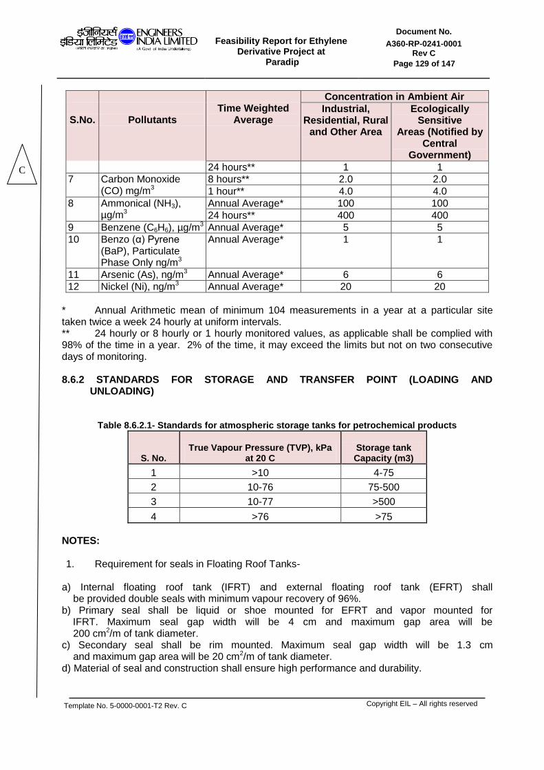
Feasibility Report for Ethylene
Derivative Project at Paradip
Document No.
A360-RP-0241-0001 Rev C
Page 129 of 147
Template No. 5-0000-0001-T2 Rev. C
Copyright EIL – All rights reserved
S.No.
Pollutants
Time Weighted
Average
Concentration in Ambient Air
Industrial, Residential, Rural
and Other Area
Ecologically Sensitive
Areas (Notified by Central
Government)
24 hours** 1 1
7 Carbon Monoxide (CO) mg/m3
8 hours** 2.0 2.0
1 hour** 4.0 4.0
8 Ammonical (NH3), µg/m3
Annual Average* 100 100
24 hours** 400 400
9 Benzene (C6H6), µg/m3 Annual Average* 5 5
10 Benzo (α) Pyrene (BaP), Particulate Phase Only ng/m3
Annual Average* 1 1
11 Arsenic (As), ng/m3 Annual Average* 6 6
12 Nickel (Ni), ng/m3 Annual Average* 20 20
* Annual Arithmetic mean of minimum 104 measurements in a year at a particular site taken twice a week 24 hourly at uniform intervals. ** 24 hourly or 8 hourly or 1 hourly monitored values, as applicable shall be complied with 98% of the time in a year. 2% of the time, it may exceed the limits but not on two consecutive days of monitoring. 8.6.2 STANDARDS FOR STORAGE AND TRANSFER POINT (LOADING AND UNLOADING)
Table 8.6.2.1- Standards for atmospheric storage tanks for petrochemical products
S. No. True Vapour Pressure (TVP), kPa
at 20 C Storage tank Capacity (m3)
1 >10 4-75
2 10-76 75-500
3 10-77 >500
4 >76 >75
NOTES: 1. Requirement for seals in Floating Roof Tanks-
a) Internal floating roof tank (IFRT) and external floating roof tank (EFRT) shall be provided double seals with minimum vapour recovery of 96%. b) Primary seal shall be liquid or shoe mounted for EFRT and vapor mounted for IFRT. Maximum seal gap width will be 4 cm and maximum gap area will be 200 cm2/m of tank diameter. c) Secondary seal shall be rim mounted. Maximum seal gap width will be 1.3 cm and maximum gap area will be 20 cm2/m of tank diameter. d) Material of seal and construction shall ensure high performance and durability.
C

Feasibility Report for Ethylene
Derivative Project at Paradip
Document No.
A360-RP-0241-0001 Rev C
Page 130 of 147
Template No. 5-0000-0001-T2 Rev. C
Copyright EIL – All rights reserved
2. Fixed roof tanks shall have vapor control efficiency of 95% and vapor balancing efficiency of 90%.
3. Inspection and maintenance of storage tanks shall be carried out under strict control. For the inspection, API RP 575 may be adopted. In-service inspection with regard seal gap should carry out once in every six months and repair to be implemented in short time; and the possibility of on-stream repair of both shall be examined.
4. Storage tanks shall be painted with white color shade, except for derogation of visually sensitive area.
8.6.3 Guidelines for LDAR and Monitoring Protocol
Leak detection and repair (LDAR) programme include (i) Block valves; (ii) Control valves; (iii) Pump seals; (iv) Compressor seals; (v) Pressure relief valves; (vi) Flanges – Heat Exchangers; (vii) Flanges – Piping; (viii) Connectors – Piping; (ix) Open ended lines; and (x) Sampling connections. Equipment and line sizes more than 2.54 cm are to be covered. LDAR programme would be applicable to components (given at 2 above) for following products/compounds: (i) hydrocarbon gases; (ii) Light liquid with vapour pressure @ 20°C > 1.0 kPa; and (iii) Heavy liquid with vapour pressure @ 20°C between 0.3 to 1.0 kPa. LDAR programme would not be applicable for (i) heavy liquids with vapour pressure < 0.3 kPa, it will be desirable to check for liquid dripping as indication of leak (ii) Equipment and line sizes less than 2.54 cm, less than 300 h service and in vacuum service. (iii) Equipments and piping during start up and shut down.(iv)Pumps (Canned, diaphragm, magnetic), Valves (Diaphragm, bellow) and close loop Sampling points and (v) Non-access able points to the extent of 5% of total plant. A leak is defined as the detection of VOC concentration more than the values (in ppm) specified below at the emission source using a hydrocarbon analyser according to measurement protocol (US EPA – 40 CFR part 60 Appendix-A, method 21 for determination of VOC leaks may be referred):
Table 8.6.3.1: Hazardous Air Pollutant (HAP) Concentrations
S. No.
Component HAP (General)
(in ppm)
w.e.f. 1.1.07
w.e.f. 1.1.10
1 Pump/ Compressor 10000 5000
2 Valves / Flanges 10000 3000
3 Other components 10000 3000
In addition, any component observed to be leaking by sight, sound or smell, regardless of concentration (liquid dripping, visible vapor leak) or presence of bubbles using soap solution should be considered as leak. Following frequency of monitoring of leaks and schedule for repair of leaks shall be followed:
C

Feasibility Report for Ethylene
Derivative Project at Paradip
Document No.
A360-RP-0241-0001 Rev C
Page 131 of 147
Template No. 5-0000-0001-T2 Rev. C
Copyright EIL – All rights reserved
Table 8.6.3.2: Frequency and Schedule of Monitoring
S. No.
Component Frequency of monitoring Repair schedule
1
Valves/ Flanges
Quarterly (semi-annual after two consecutive periods with < 2% leaks and annual after 5 periods with < 2% leaks)
Repair will be started within 5 working days and shall be completed within 15 working days after detection of leak for general hydrocarbons. In case of benzene, the leak shall be attended immediately for repair.
2 Pump seals Quarterly
3 Compressor seals
Quarterly
4 Pressure relief devices
Quarterly
5 Pressure relief devices (after venting)
Within 24 hours
6 Heat Exchangers Quarterly
7 Process drains Annually
8 Components that are difficult to monitor
Annually
9 Pump seals with visible liquid dripping
Weekly Immediately
10 Any component with visible leaks
Weekly Immediately
11 Any component after repair/ replacement
Within a week -
Following types of monitoring methods may be judiciously employed for detection of leaks: (i) Photo ionisation detector (PID) or flame ionisation detector (FID) Instrumental method of measurement of leaks; (ii) Audio, visual and olfactory (AVO) leak detection; and (iii) Soap bubble method. Data on time of measurement & concentration value for leak detection; time of repair of leak; and time of measurement & concentration value after repair of leak should be documented for all the components. Pressure relief and blow down systems should discharge to a vapour collection and recovery system or to flare. Open-ended lines should be closed by a blind flange or plugged.
C

Feasibility Report for Ethylene
Derivative Project at Paradip
Document No.
A360-RP-0241-0001 Rev C
Page 132 of 147
Template No. 5-0000-0001-T2 Rev. C
Copyright EIL – All rights reserved
Totally closed-loop should be used in all routine samples. Low emission packing should be used for valves. High integrity sealing materials should be used for flanges. 8.6.4 GENERAL NOTES
1. Emission monitoring shall be carried out as per the Emission Regulations – Part III,
published by Central Pollution Control Board. 2. Following methods may be used for measurement of pollutant concentrations in the
emissions: Table 8.6.4.1 : Method of Measurement of emissions
S. No. Parameter Method of measurement
1 Sulphur Dioxide (SO
2)
USEPA CFR – 40 Part 60 Appendix A Method 6
2 Oxides of Nitrogen (NO
x)
USEPA CFR – 40 Part 60 Appendix A Method 7
3 Particulate Matter (PM)
USEPA CFR – 40 Part 60 Appendix A Method 5
4 Carbon Monoxide (CO)
USEPA CFR – 40 Part 60 Appendix A Method IOA / Combustion analyzer with electro chemical detect or / NDIR detector
8.6.5 GASEOUS EMMISION Gaseous emissions for Configuration-6C as provided by respective unit licensors are given below:
Table 8.6.5.1: Gaseous effluent for ER & MEG BLock (For Configuration-6C)
UNIT GASEOUS EFFLUENT
DESCRIPTION FREQUENCY QUALITY QUANTITY DESTINATION
ERU
BLANKETING GAS FROM GENERAL BLANKETING INTERMITTENT Nitrogen
0 ATMOSPHERE
LEAKAGE FROM BINARY REFRIGERANT COMPRESSOR CONTINOUS
Nitrogen, Ethylene, Propylene
Normal = 10 kg/hr Max= By DEC ATMOSPHERE
MEG REGENERATOR CONDENSER VAPOR CONTINOUS
CO2, Water, Ethylene 20191 kg/hr ATMOSPHERE
C

Feasibility Report for Ethylene
Derivative Project at Paradip
Document No.
A360-RP-0241-0001 Rev C
Page 133 of 147
Template No. 5-0000-0001-T2 Rev. C
Copyright EIL – All rights reserved
8.7 NOISE ENVIRONMENT Ambient Standard for Noise, specified by CPCB is given below in Table-8.7.1.
Table 8.7.1: Ambient Air Quality Standards in respect of Noise
S. No. Area Code Category of Area Limit in dB (a) Leg
Day Time Night Time
1 A Industrial area 75 70
2 B Commercial area 65 55
3 C Residential area 55 45
4 D Silence zone 50 40
Notes : 1.Daytime is reckoned in between 6 am and 9 pm 2. Nighttime is reckoned in between 9 pm and 6 am
3. Silence zone is defined as areas upto 100 meters around such Premises as hospitals, educational institutions and courts. The Silence zones are to be declared by the competent authority.
4. Mixed categories of areas should be as "one of the four above Mentioned categories" by the competent authority and the Corresponding standard shall apply.
Comprehensive measures for noise control will be followed at the design stage in terms of:
- Noise level specification of various rotating equipment as per Occupational Safety and Health Association (OSHA) standards.
- Equipment layout considering segregation of high noise generating sources.
- Erecting suitable enclosures, if required, to minimize the impact of high noise generating sources.
8.8 WATER ENVIRONMENT Several measures are proposed to be incorporated at the designs stage towards minimizing the generation of wastewater and treatment of the generated effluent. Some of these measures are described below:
Closed blow down system will be incorporated for hydrocarbon liquid discharges in all the process units, which will reduce the wastewater load to ETP both in terms of quantum load and quality. This is another of the in-plant control measures.
Appropriate segregation and collection philosophy (separate sewers for process waste, contaminated rainwater, spent caustic, cooling tower blow down, boiler blow down, etc.) will be incorporated for various effluents depending on individual stream characteristics.
A comprehensive wastewater management system to comply with treated effluent quality for disposal as specified by CPCB shall be established.
Process area will be paved to avoid contamination of soil/sub-soil/ground water in configuration of accidental spill/leakage of hydrocarbon liquids.
8.8.1 LIQUID EFFLUENT Liquid effluent for Configuration-6C of Ethylene Derivative Complex as provided by respective unit licensors is provided below:
C

Feasibility Report for Ethylene
Derivative Project at Paradip
Document No.
A360-RP-0241-0001 Rev C
Page 134 of 147
Template No. 5-0000-0001-T2 Rev. C
Copyright EIL – All rights reserved
Table 8.8.1.1: Liquid Effluent details for Configuration-6C
UNIT LIQUID EFFLUENT
DESCRIPTION FREQUENCY QUALITY QUANTITY DESTINATION
ERU
SPENT CAUSTIC
CONTINUOUS Water, Sodium Hydroxide,
Sodium Carbonate, Sodium Sulphide
Normal = 617 kg/hr Max= 710 kg/hr
Refinery Spent Caustic
Treatment Plant
OILY WASTE WATER
CONTINUOUS Phenols, BOD, COD, TSS Normal = 1868 kg/hr
Max= 2148 kg/hr Refinery ETP
MEG CONTINOUS Water containing Sodium salts, glycols and traces of
aldehydes, BOD, COD, TDS 25070 kg/hr Refinery ETP
UTILITY
BLOW DOWN FROM
COOLING TOWER CONTINOUS
205 m3/hr Refinery ETP
NON-PROCESS
CRWS INTERMITTENT TSS, OIL, BOD, COD 25 m
3/day Refinery ETP
UNIT FLOOR WASH
INTERMITTENT (ONCE IN 2
DAYS FOR 2 HOURS) TSS, OIL, BOD, COD 10 m
3/day
Refinery ETP
SANITARY WASTE
CONTINUOUS TSS, BOD, COD 1 m
3/hr
Refinery ETP
Liquid effluent from Ethylene Derivative Complex for Configuration-6C is treated in the existing Refinery Effluent Treatment Plant. Hence, no new ETP is envisaged for the Ethylene Derivative Complex. 8.9 LAND ENVIRONMENT During the design stage itself due care will be taken to select the process technologies generating minimum solid wastes so that their handling, treatment and disposal do not cause any serious impact on the existing land environment. Also, efforts will be made to recycle some of the spent catalysts & resins by way of returning to the original supplier for reprocessing. The solid wastes management plan proposed is briefly described below. The provisions of Hazardous Waste (Management & Handling) Rules, 1989 and its subsequent Amendments will be complied with. There are primarily four types of solid wastes generated in a Petrochemical industry: 1. Spent Catalysts 2. Spent resins 3. ETP Sludges 4. General Solid Wastes 5. Tank Bottom Sludge
C

Feasibility Report for Ethylene
Derivative Project at Paradip
Document No.
A360-RP-0241-0001 Rev C
Page 135 of 147
Template No. 5-0000-0001-T2 Rev. C
Copyright EIL – All rights reserved
8.9.1 SOLID EFFLUENT Solid effluent as provided by respective unit licensors for Configuration-6C has been tabulated below:
Table 8.9.1.1: Solid Effluent for configuration-6C
UNIT SOLID EFFLUENT
DESCRIPTION COMPOSITION FREQUENCY QUANTITY CLASSIFICATION
ERU
SPENT CATALYST FROM CHLORIDE
TREATER (NOTE-1)
SUD-CHEMIE ACTISORB CL2
CATALYST
ONCE/ 2.5 YEARS
34.2 m³ catalyst 3 m³ ceramic balls
NON HAZARDOUS
SPENT CATALYST FROM OXYGEN
CONVERTER (NOTE-2)
SULFIDED COPPER
CATALYST (BASF
PURISTAR R3-81)
ONCE/4 YEARS
2 x 96617 kg catalyst 2 x 5 m³ ceramic balls
NON HAZARDOUS
SPENT ADSORBENT FROM DRYER
TREATER (NOTE-3)
BASF SELEXSORB CD
ADSORBENT
ONCE/2 YEARS
88489 kg adsorbent 6.4 m³ ceramic balls
NON HAZARDOUS
SPENT ADSORBENT FROM MERCURY
ADSORBER (NOTE-4)
PROMOTED CARBON (ASM
CATALYSTS ESM 300)
ONCE/ 3 YEARS
17723 kg adsorbent 4.2 m³ ceramic balls
NON HAZARDOUS
MEG
SULFUR GUARD BED CATALYST
90 % Zinc ONCE/4 YEARS
15663 kg NON
HAZARDOUS
EO Reactor Catalyst Silver on Alumina ONCE/4 YEARS
165,932 kg NON
HAZARDOUS
Cycle Water Treating Unit Cation Resin
Polystyrene chain ONCE/4 YEARS
13835 kg NON
HAZARDOUS
Cycle Water Treating Unit Anion Resin
Polystyrene chain ONCE/4 YEARS
20558 kg NON
HAZARDOUS
MEG Post Treatment Resin
ONCE/4 YEARS
6486 kg NON
HAZARDOUS
NOTES: 1. ActiSorb Cl2 (G-92C) is an alkylized alumina oxide catalyst, containing 84 - 96% Al2O3. The catalyst is stripped to remove hydrocarbons prior to removal from vessel. The stripped catalyst should be transferred to a regeneration facility, or disposed of, in accordance with local environmental regulations. 2. Puristar R3-81 is a sulfided copper catalyst consisting of tablets of CuO, also containing magnesium oxide, graphite, talc and barium oxide. The catalyst is stripped to remove hydrocarbons prior to removal from vessel. The stripped catalyst should be transferred to a regeneration facility, or disposed of, in accordance with local environmental regulations. 3. Selexsorb CD is a promoted alumina-based adsorbent consisting of 95.1wt% of Al2O3 (+ modifier), 0.02wt% SiO2, 0.02wt% Fe2O3, 0.3wt% Na2O and 4.5wt% LOI (250-1100°C). The adsorbent is stripped to remove hydrocarbons prior to removal from vessel. The stripped adsorbent should be transferred to a regeneration facility, or disposed of, in accordance with local environmental regulations.
C

Feasibility Report for Ethylene
Derivative Project at Paradip
Document No.
A360-RP-0241-0001 Rev C
Page 136 of 147
Template No. 5-0000-0001-T2 Rev. C
Copyright EIL – All rights reserved
4. ESM 300 is an adsorbent consisting of pellets of activated coal-based carbon, which have been impregnated with inorganic salts. ESM 300 contains 80 - 90 wt% activated carbon and 10 - 20 wt% sulfur. The adsorbent is stripped to remove hydrocarbons prior to removal from vessel. Adsorbent can be landfilled after chemical and physical treatment, when in compliance with local regulations.
8.10 POLLUTION CONTROL MEASURE IN CONSTRUCTION PHASE The overall impact of the pollution on the environment during construction phase is localised in nature, reversible and is for a short period. Air The suspended particulate pollution generated during transportation will be mitigated by covering the vehicles so as to ensure no spillage. Hosing down the wheels of the vehicles with water and providing washing troughs for them would further mitigate the amount of dust generated. In addition, emission of other pollutants from construction machinery using diesel driven prime movers, will be controlled by proper maintenance. Noise Noise emissions from construction equipment will be kept to a minimum by regular maintenance. Heavy and noisy construction work will be avoided during night time. Water Drinking and sanitation facilities at the Petrochemical complex will be provided to the construction workforce. This is necessary to reduce pollution of any receiving water body and also to prevent hazards due to water borne vectors. Potable water shall be provided to the workers. Socio Economic R & R plan as approved by District Collector will be strictly adhered and compensation will be provided. 8.11 POLLUTION CONTROL MEASURE IN OPERATION PHASE It is envisaged that with strict adherence to the pollution prevention and control measures during the design stage, the environmental impacts could be moderated to the minimum possible level during the operation phase. Air (A) In-plant Control Measures Some of the important operational measures, which can reduce the impact on air environment, are as follows: -Ensuring the operations of various process units as per specified operating guidelines/operating manuals.
C

Feasibility Report for Ethylene
Derivative Project at Paradip
Document No.
A360-RP-0241-0001 Rev C
Page 137 of 147
Template No. 5-0000-0001-T2 Rev. C
Copyright EIL – All rights reserved
-Strict adherence to maintenance schedule for various machinery/equipment. -Good house keeping practices (B)Stack and Ambient Air Monitoring In order to keep a check on the emissions of SO2, NOx, SPM and CO from reactor/regenerator, boiler and furnace stacks shall be monitored as per statutory regulations. Continuous monitors for emissions shall be installed on all major stacks. Ambient Air Monitoring Stations shall continuously monitor quality of the air in the vicinity of the Petrochemical complex premises. Laser based instruments for measuring Sulfur Dioxide, NOx, Particulate matters, Ozone, Lead, Ammonia, Benzene, Benzo(a)Pyrene, Arsenic, Nickel, Carbon Monoxide, Hydrocarbons shall be used in these Monitoring Stations. Noise As the plant is going to be operational on a 24-hour basis, noise considerations are very important. All equipments will be specified to meet 85 dB (A) at 1 m distance. The exposure of employees working in the noisy area shall be monitored regularly to ensure compliance with the OSHA requirements. A green belt of appropriate width around the Petrochemical complex will be developed. Treated Sewage will be used for irrigating this belt. This green belt will help to reduce the noise and visual impact upon the surrounding population as much as possible. Water (A) In-plant Control Measures Some of the measures, which can be taken up during operational phase of the complex are: -Reducing the actual process water consumption by way of improvement in operation of processing units. -Looking into more options of reusing the treated effluent besides fire water make up or for horticulture development. - Ensuring proper monitoring and maintenance schedule for the effluent treatment plant. -Providing reuse and recycle of the treated effluent and water. (B) Water Quality Monitoring The monitoring of raw influent, treated effluent and the ground water quality in the surrounding areas will be carried out regularly. For regular monitoring of the operation of various pollution control facilities, a laboratory with sophisticated instruments and well-trained manpower shall be established. A separate Pollution Control Cell with qualified Chemical Engineers/Scientists also form part of the facility, which will ensure that all pollution control measures are effectively operating and to carry out day-to-day checks, trouble shooting and further improvements wherever necessary. Land To improve the environmental quality following measures are recommended.
C
Feasibility Report for Ethylene
Derivative Project at Paradip
Document No.
A360-RP-0241-0001 Rev C
Page 138 of 147
Template No. 5-0000-0001-T2 Rev. C
Copyright EIL – All rights reserved
(A) In-plant Control Measures -The solid waste generated in the form of packaging material etc. shall be sold off for making it suitable for reuse by reprocessing. -The solids wastes identified to be sent to nearby authorized landfill agency for further disposal. -In order to improve the aesthetics in the plant surrounding, further plantation shall be carried out the around the plant boundary. Socio-Economic Since the project is big in nature it will affect the socio-economic status of the region due to high intensive investment, development of infrastructure such as road, railways communication, education and other common facilities. There will be cascading effects on economic status and avenues in the area as well as in the buffer zone where in there will be growth in employment scenario. However there will be adverse impact in terms of usage of common resources as well as rise in the price of commodities and environmental pollution However, JV shall take part actively in the overall development of the area. 8.12 ENVIRONMENT CELL A Plant Safety & Environment Department under its technical services department, which consists of well-qualified and experienced technical personnel from the relevant fields, will be in place to look after Environment cell.
C
Feasibility Report for Ethylene
Derivative Project at Paradip
Document No.
A360-RP-0241-0001 Rev C
Page 139 of 147
Template No. 5-0000-0001-T2 Rev. C
Copyright EIL – All rights reserved
SECTION 9.0
PROJECT IMPLEMENTATION
AND SCHDULE

Feasibility Report for Ethylene
Derivative Project at Paradip
Document No.
A360-RP-0241-0001 Rev C
Page 140 of 147
Template No. 5-0000-0001-T2 Rev. C
Copyright EIL – All rights reserved
9.0 PROJECT IMPLEMENTATION AND SCHEDULE Zero date of the project is considered to be the date of investment approval completion by IOCL. The project schedule has been attached as Annexure XVI for Configuration-6C (EPCM). Following can be noted for the same-
Mechanical completion of the project is considered to be 37 months from the date of project management consultant selection.
Project management consultant is selected by IOCL one month after zero date.
Following to be noted regarding the project schedule of LSTK and Mixed mode implementation of Configuration-6C-
Mechanical completion of the project is considered to be 39.5 months from the date of project management consultant selection.
Project management consultant is selected by IOCL one month after zero date.
Job closure is considered to be 43.5 months from the date of project management consultant selection.
C

Feasibility Report for Ethylene
Derivative Project at Paradip
Document No.
A360-RP-0241-0001 Rev C
Page 141 of 147
Template No. 5-0000-0001-T2 Rev. C
Copyright EIL – All rights reserved
SECTION 10.0
PROJECT COST ESTIMATE
Feasibility Report for Ethylene
Derivative Project at Paradip
Document No.
A360-RP-0241-0001 Rev C
Page 142 of 147
Template No. 5-0000-0001-T2 Rev. C
Copyright EIL – All rights reserved
10.0 PROJECT COST ESTIMATE
A write up on Project cost estimate along with project cost sheets and financial analysis for all the configuration of the proposed Ethylene derivative complex are enclosed in Annexure XIII.

Feasibility Report for Ethylene
Derivative Project at Paradip
Document No.
A360-RP-0241-0001 Rev C
Page 143 of 147
Template No. 5-0000-0001-T2 Rev. C
Copyright EIL – All rights reserved
SECTION 11.0
FINANCIAL ANALYSIS

Feasibility Report for Ethylene
Derivative Project at Paradip
Document No.
A360-RP-0241-0001 Rev C
Page 144 of 147
Template No. 5-0000-0001-T2 Rev. C
Copyright EIL – All rights reserved
11.0 FINANCIAL ANALYSIS
A write up on Project cost estimate along with project cost sheets and financial analysis for all the configuration of the proposed Ethylene derivative complex are enclosed in Annexure XIII.

Feasibility Report for Ethylene
Derivative Project at Paradip
Document No.
A360-RP-0241-0001 Rev C
Page 145 of 147
Template No. 5-0000-0001-T2 Rev. C
Copyright EIL – All rights reserved
SECTION 12.0
RECOMMENDATION

Feasibility Report for Ethylene
Derivative Project at Paradip
Document No.
A360-RP-0241-0001 Rev C
Page 146 of 147
Template No. 5-0000-0001-T2 Rev. C
Copyright EIL – All rights reserved
12.0 RECOMMENDATION
Configuration 6C has been worked out with the following considerations-
a. IOCL confirmed that the Steam and Power for Configuration 6C will be supplied from the Refinery. Thus, Ethylene Derivative Complex will not have any CPP/STG.
b. IOCL confirmed that the Refinery ETP can accommodate the extra load contributed by C2 derivative complex. Hence no new ETP has been considered for Configuration 6C.
c. As informed by IOCL, Instrument air, Plant air and Nitrogen required for Configuration 6C will be supplied from the Refinery Compressed air plant and Nitrogen Plant. Thus, no new facility generating compressed air and nitrogen have been envisaged as part of the C2 derivative complex for Configuration 6C.
d. DM water required for Configuration 6C will be supplied from the Refinery DM water plant. Hence, DM plant has not been considered in the Ethylene Derivative Complex.
e. Recycle Compressor of MEG Unit is considered to be driven by steam (VHP to HP/Condensing). LP Steam, as required by the complex shall be generated by letting down HP Steam via PRDS located in MEG Unit.
With reference to the economic summary of all the configuration studied and tabulated in table 1.12.1 above; (iv) Configuration 6C (EPCM) emerges to be the option with Highest IRR, highest NPV,
Lowest Total OPEX and minimum capex.
(v) Configuration 4 emerges with the maximum Sales but with significantly low IRR , NPV vis a vis Configuration 6C (EPCM); this configuration also has the highest Total Opex and significantly high CAPEX as compared to Configuration 6C (EPCM)
(vi) The schedule will remain the same as informed above and the cash flows, CAPEX,
IRRs, Taxation etc can be reassessed at IOCL’s end based on their experience and choice of execution methodology.
With above as basis, Configuration 6C (EPCM) can be considered for pursuing further in detail feasibility report stage.
C