Final Exam Fall 201 v6-with-solution - WeeklyJoys 20100 – Fall 2016 Final Exam ... Answer (7)...
22
1 ECE 20100 – Fall 2016 Final Exam December 12, 2016 Sections (include on scantron) Hosseini (9:30) – 0002 Peleato-Inarrea (3:30) – 0004 Michelusi (1:30) – 0005 Qi (10:30) – 0011 Cui (8:30) – 0012 Peroulis (11:30) – 0013 Kildishev (1:30) – 0014 Name ____________________________ PUID____________ Instructions 1. DO NOT START UNTIL TOLD TO DO SO. 2. Write your name, section, professor, and student ID# on your Scantron sheet. We may check PUIDs. 3. This is a CLOSED BOOKS and CLOSED NOTES exam. 4. The use of a TI-30X IIS calculator is allowed, but not necessary. 5. If extra paper is needed, use the back of test pages. 6. Cheating will not be tolerated and will be dealt with according to the policy in your section. In particular, continuing to write after the exam time is up is regarded as cheating. 7. If you cannot solve a question, be sure to look at the other ones, and come back to it if time permits. By signing the scantron sheet, you affirm you have not received or provided assistance on this exam.
Transcript of Final Exam Fall 201 v6-with-solution - WeeklyJoys 20100 – Fall 2016 Final Exam ... Answer (7)...

1
ECE 20100 – Fall 2016
Final Exam
December 12, 2016
Sections (include on scantron)
Hosseini (9:30) – 0002 Peleato-Inarrea (3:30) – 0004 Michelusi (1:30) – 0005
Qi (10:30) – 0011 Cui (8:30) – 0012
Peroulis (11:30) – 0013 Kildishev (1:30) – 0014
Name ____________________________ PUID____________
Instructions
1. DO NOT START UNTIL TOLD TO DO SO.
2. Write your name, section, professor, and student ID# on your Scantron sheet. We may check PUIDs.
3. This is a CLOSED BOOKS and CLOSED NOTES exam.
4. The use of a TI-30X IIS calculator is allowed, but not necessary.
5. If extra paper is needed, use the back of test pages.
6. Cheating will not be tolerated and will be dealt with according to the policy in your section. In particular, continuing to write after the exam time is up is regarded as cheating.
7. If you cannot solve a question, be sure to look at the other ones, and come back to it if time permits.
By signing the scantron sheet, you affirm you have not received or provided assistance on this exam.

2
Question 1 A resistor of unknown resistance has a 4 A current passing through it, as shown. The power absorbed by the resistor is 12 W. Find the voltage (in V) across the resistor for these conditions.
(1) 1 V
(2) 2 V
(3) 3 V
(4) 4 V
(5) -1 V
(6) -2 V
(7) -3 V
(8) -4 V
(9) None of the above
Answer (7) Solution: We can write that I = - 4 A to follow passive sign convention. As P = V ´ I, then for given ± signs, V = 12 W/ (-4 A) = - 3V.

3
Question 2 For the circuit below, find the voltage, VBC (in V):
(1) 2
(2) 8
(3) 10
(4) 12
(5) 20
(6) -2
(7) -8
(8) -10
(9) -12
(10) None of the above
Answer (8) Solution I1 = 5 V /(3 + 2)W = 1 A; VB = 1 A ´ 2W = 2 V; VC = 4 A ´ (2 + 1) W = 12 V; VBC = VB – VC = 2 – 12 = – 10 V.

4
Question 3 Find the node voltage, VA (in V).
(1) 1.2
(2) 2.4
(3) 3.6
(4) 4.0
(5) 5.0
(6) 6.8
(7) 7.2
(8) 8.0
(9) None of the above
Answer (7) Solution
Using nodal analysis for node A:210
3 , 2 1
10where
2102
10 2Therefore 3 2 102 1
10 6 4 2036
So = =7.2 5
A xA
Ax
AA
AA
A A
A
V iV
Vi
VVV
V
V V
V
--+ =
-=
-æ ö- ç ÷- è ø+ = = -
- + = -

5
Question 4 Using source transformations or any other analysis technique, find the value of the Norton Equivalent current source (in A) for the circuit below.
(1) 1
(2) 2
(3) 3
(4) 4
(5) 5
(6) 6
(7) 7
(8) 8
(9) 9
(10) None of the above
Answer (4) SOLUTION Transform 6A || 4 W into 24V connected in series with 4 W+4 W then add two current sources (3A+1A) with 8 W || 8 W to obtain (4A). Alternatively, one can short the two terminals, then the 8 W resistor is shorted, and the 6A current source is split even (3 A each) for the two 4 W resistors. This 3 A plus the other current source (1 A) is the current flowing through the shorted terminals. So the short circuit current is 4 A.

6
Question 5 The linear circuit below consists of resistors and sources only. Experiments were performed to evaluate circuit parameters. Two current/voltage relationships were found to be:
v = 10 V, iL = 0 A v = -10 V, iL = 2 A
Find the value of the Thevenin equivalent resistance, RTH, for the linear circuit (in W).
(1) 10
(2) 2
(3) 30
(4) 4
(5) 5
(6) 20
(7) 40
(8) 8
(9) None of the above
Answer (1) SOLUTION v = voc - Rth iL. At iL = 0 voc = 10; and for iL = 2 A, -20 = - 2 Rth; Rth = 10 [W].

7
Question 6
The current through an inductor when connected to a resistor, R, in a zero-input (undriven), first-order RL circuit is:
iL(t) = 2 e-3t A t ³ 0
The instantaneous stored energy in the inductor at t = 0 is known to be 400 mJ. Find the value of the resistance to which the inductor is connected (in W).
1) 0.1
2) 0.2
3) 0.3
4) 0.4
5) 0.5
6) 0.6
7) 0.7
8) 0.8
9) 0.9
10) none of the above
Answer (6) SOLUTION As 400 mJ = 0.5LiL
2 and t = L/R = 1/3 s-1; iL (0) = 2 A; à L = 0.2 H and R = 0.6 W.

8
Question 7 The capacitor voltage in a driven, first-order RC circuit with a constant voltage source is:
vC(t) = 5 - 8 e-4t V t ³ 0
Find the value of vC(0-) (in V).
1) 1
2) 2
3) 3
4) 4
5) 5
6) -1
7) -2
8) -3
9) There is insufficient information
10) none of the above
Answer (8) SOLUTION vC(t) = 5 - 8 e-4t V vC(0-) = vC(∞) – (vC(to
+) - vC(∞)) V and since vC(∞) = 5 V; vC(0-) = – 3 V.

9
Question 8 In the circuit below, the switch has been closed for a long time. At t = 0 sec, the switch opens. Assuming a solution for the capacitor voltage of the form,
vC(t) = A cos(wt) + B sin(wt) V find the closest value for the constant B.
(1) -0.1
(2) -0.2
(3) -0.3
(4) -0.4
(5) -0.5
(6) -0.6
(7) -0.7
(8) -0.8
(9) None of the above
Answer (3) SOLUTION Since (the inductor is a short) vC(0+) = A cos(0) = 0 V; then constant A = 0. So at t = 0, iC = C dvC(t)/dt = C ´ B ´ (1/√LC) = – iL = – 0.5 ´ 0.2 A; and finally B = – 0.3 .

10
Question 9
The switch in the circuit below has been opened for a long time. It closes at t = 0 s. Find dtdv c at
t = 0+ (in V/s).
(1) 1
(2) 2
(3) 3
(4) 4
(5) 5
(6) 6
(7) 7
(8) 8
(9) None of the above
Answer (6) Solution: ( ) ( ) ( ) ( )
( ) ( )( ) ( ) ( ) ( )
0
1Since , 0
At 0 , all energy stored in the capacitor and inductor has been dissipated,
So 0 0, 0 0.
Due to the continuity, 0 0 0, 0 0 0
After the switch is cl
C CC C
t
C L
C C L L
dv t dv tC i t i
dt dt C
t
v i
v v i i
+
+
=
-
- -
+ - + -
= =
=
= =
= = = =
osed, at the moment of 0 , the capacitor can be viewed asa voltage source of 0 (short circuit), and the inductor can be viewed as a current sourceof 0 (open circuit). Therefore the 1 resistor is
t +=
W
( )( ) ( )
0
shorted by the capacitor, and12 V
0 3 A4
1 3and 0 6 V/sec.
0.5
C
CC
t
i
dv ti
dt C+
+
+
=
= =W
= = =

11
Question 10 Find the characteristic equation for the circuit below for t > 0.
(1) s2 + 0.1s + 0.2 = 0
(2) s2 + 4s + 0.2 = 0
(3) s2 + 8.33s + 0.833 = 0
(4) s2 + 2s + 0.2 = 0
(5) s2 + 16.67s + 0.833 = 0
(6) s2 + 0.2s + 0.833 = 0
(7) s2 + 5s + 1 = 0
(8) None of the above
Answer (4) SOLUTION: Introduce node A shown below.
( )
2
2
Choose as the variable, we have
8KCL at node A: 2 3 ; therefore: 2 10 3
0.1
5 10 0 So the characteristic equation i
I IL A
L L
A A A LL L
L LL
di dii V Ldt dt
di did dd V V dV didt dti idt dt dt dt dt
d i di idt dt
= =
æ ö æ öç ÷ ç ÷- è ø è ø= + + - = + +
+ + = 2 2s: 5 10 1 0, or 2 0.5 0s s s s+ + = + + =
A
12
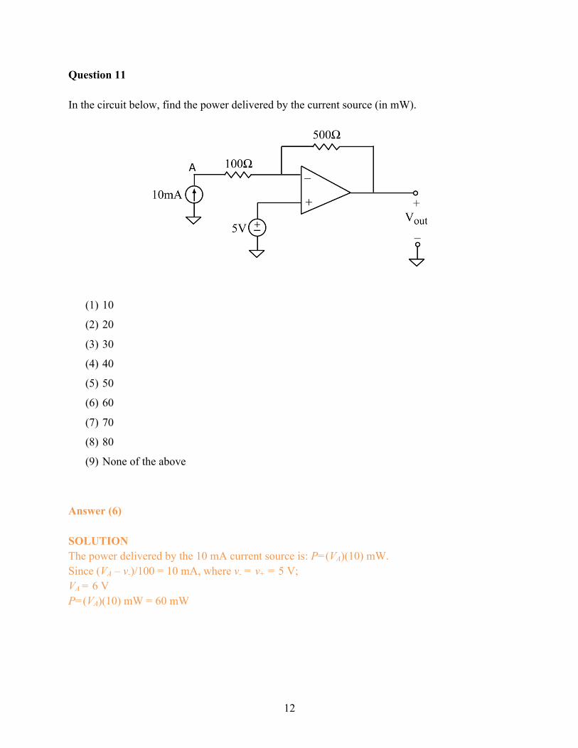
Question 11 In the circuit below, find the power delivered by the current source (in mW).
(1) 10
(2) 20
(3) 30
(4) 40
(5) 50
(6) 60
(7) 70
(8) 80
(9) None of the above
Answer (6) SOLUTION The power delivered by the 10 mA current source is: P=(VA)(10) mW. Since (VA – v-)/100 = 10 mA, where v- = v+ = 5 V; VA = 6 V P=(VA)(10) mW = 60 mW

13
Question 12 Given the phasor currents shown below, determine the phasor current (in A) through the capacitor.
(1) j
(2) 2j
(3) 3j
(4) 4j
(5) 5j
(6) 3 + 4j
(7) 3 + 2j
(8) 3 + 5j
(9) None of the above
Answer (2) SOLUTION Is = IC + IL + IR; IC = 2j;

14
Question 13 The input impedance in the circuit below is 1 Ð -60o W. Find the instantaneous power generated by the source (in W).
(1) 100 + 50 cos(10t - 60°)
(2) 100 + 25 cos(10t - 120°)
(3) 25 + 25 cos(10t - 60°)
(4) 25 + 50 cos(10t - 120°)
(5) 50 + 25 cos(10t - 60°)
(6) 50 + 50 cos(10t - 60°)
(7) 75 + 50 cos(10t - 120°)
(8) 75 + 25 cos(10t - 60°)
(9) 100
(10) None of the above
Answer (4) SOLUTION iIN = 10 Ð -90o / 1 Ð -60o = 10 Ð -30o = 10cos(5t - 30°) => pIN (t) = 10cos(5t - 90°)10cos(5t - 30°) = 0.5´[100cos(60°) + 100cos(10t - 120°)] = 25 + 50 cos(10t - 120°);

15
Question 14 Find the average power (in W) absorbed by the 6 W resistor in the circuit shown below.
(1) 1
(2) 2
(3) 3
(4) 0.5
(5) 0.33
(6) 6
(7) 12
(8) 1.5
(9) None of the above
Answer (1) SOLUTION is(t) = t , 0 < t < 1 s; 0, is(t) = t, 1 < t < 2 s; Pave = !
"#"$%# =!
(!)1+6 =1W

16
Question 15 Find the effective (rms) voltage for the waveform shown below (in V).
(1) 1
(2) 2
(3) √3
(4) 4
(5) √2
(6) 6
(7) 2√2
(8) (2/3)√3
(9) None of the above
Answer (5) SOLUTION
VRMS = -(/)12
3+
= "45+= 2

17
Question 16 Find the reactive power (in VAR) for the capacitor (rms) voltage given a source voltage of v(t) = 50√2 sin(10 t) V.
(1) 25
(2) -25
(3) 50
(4) -50
(5) 100
(6) -100
(7) 50√2
(8) -50√2
(9) None of the above
Answer (2) SOLUTION v(t) = 50√2 sin(10 t) V 7 # = 50 2 cos 10# − 90° ; ABCC = −D50V; FBCC =
(GHI(J)GH!((K
= 0.5A;NO[ABCCFBCC∗ ] =-25 VAR.

18
Information for next 2 problems A voltage source supplies power to four machines. The complex power absorbed by each machine is: S1 = 75 + 60 j S2 = 110 + 80 j S3 = 125 + 100 j S4 = 90 + 60 j Question 17 Find the apparent power (in VA) delivered by the source (i.e. │SS│).
(1) 100
(2) 200
(3) 300
(4) 400
(5) 500
(6) 600
(7) 700
(8) 800
(9) None of the above
Answer (5) SOLUTION │SS│ = | 75 + 110 + 125 + 90 + 60 j + 60 j + 80 j + 100 j | = | 400 + j300| = 500 VA Question 18 Find the power factor for the source.
(1) 0.70 leading
(2) 0.75 leading
(3) 0.80 leading
(4) 0.85 leading
(5) 0.70 lagging
(6) 0.75 lagging
(7) 0.80 lagging
(8) 0.85 lagging
(9) None of the above

19
Answer (7) SOLUTION: pf = 400/500 = 0.8 lagging, since Q = Im[Ss] > 0.
Question 19
In the circuit below, the complex power absorbed by loads ‘1’ and ‘2’ are,
S1 = 12 kW – j16 kVAR S2 = 8 kW + j 6 kVAR
If a capacitor or an inductor is added to the circuit (as shown in dashed line), what is proper selection below that gives a power factor of 0.95 leading:
(1) Capacitor: C = 0.116 F
(2) Capacitor: C = 0.584 F
(3) Capacitor: C = 1.713 F
(4) Capacitor: C = 2.919 F
(5) Inductor: L = 0.116 H
(6) Inductor: L = 0.584 H
(7) Inductor: L = 1.713 H
(8) Inductor: L = 2.919 H
(9) None of the above
Answer (6) SOLUTION
Ss = 20 kW – j10 kVA; S = −T !UV1
− 1; SWXY = −20 !(.ZI1
− 1 = −6.5737kVAR → ΔQ =
3.4263 = !(c2´!((´!((Id
; L = 0.5837.
100Ö2 cos(5t) V
+ _ 1 2 C or L

20
Question 20
In the circuit below, ������ the load impedance for maximum power transfer to the load resistor Rload.
(1) 1 + j
(2) 1 – j
(3) 1 + 2j
(4) 1 – 2j
(5) 2 + 4j
(6) 2 – 4j
(7) 2 + 2j
(8) 2 – 2j
(9) None of the above
Answer (5) SOLUTION VOC = -40j V; isc = 10 (1/2)/(1/2 - 1/j4) = 20(2 - j) = 4(2 - j); Zth = -40j/4(2 - j) = -2j(2 - j) = (2 - 4j) -> ZL = (2 - 4j)* = (2 + 4j)

21
Potentially Useful Formulas
First order circuit: ( )ot t /ox(t) x( ) x(t ) x( ) e
+- - t+é ù= ¥ + - ¥ë û , t = L/R or t = RC
Series RLC: 2 R 1s s 0L LC
+ + =
Parallel RLC: 2 1 1s s 0RC LC
+ + =
( ) td dx(t) x( ) Acos t Bsin t e-s= ¥ + w + w
( ) tx(t) x( ) A Bt e-s= ¥ + +
( )1 2s t s tx(t) x( ) Ae Be= ¥ + +
2
21 2
b b 4cs ,s for s bs c 0
2- ± -
= + + = , where ( ) 1c LC -=
R / 2L (series)
b12 (parallel)2RC
ìïs = = íïî
o 1LC
w =
2 2
1,2 os = -s± s -w
22 2
d o4c b2-
w = = w -s
24
Potentially Useful Formulas (2nd Midterm)
00
( )/( ) ( ) ( ) ( )� � � Wª º f � � f¬ ¼t tx t x x t x e , where THR CW or
TH
LR
W
� � � �
00
2 20 1 1 0
( )( )
1( ) ( ) ( )
( , ) ( ) ( )2
LL
t
L L Lt
L L L
di tv t Ldt
i t i t v t dtL
LW t t i t i t
c c �
ª º �¬ ¼
³
� � � �
00
2 20 1 1 0
( )( )
1( ) ( ) ( )
( , ) ( ) ( )2
CC
t
C C Ct
C C C
dv ti t Cdt
v t v t i t dtC
CW t t v t v t
c c �
ª º �¬ ¼
³
1ln lnx
x�
Elapsed time formula: t2 - t1 = W ln[(X1 - x(∞))/(X2 - x(∞))]

22
cos g cos h =
12 cos g − h + cos g + h
sin g sin h =12 cos g − h − cos g + h
sin g cos h =12 sin g − h + sin g + h
26
Potentially Useful Formulas (since Exam 3)
0
1( ) cos( ) cos( ) cos( )
2
Tm m
ave V I eff eff V I rms rms V IV IP p t dt V I V I
T T �T T �T T �T³
* * *1
2 m m eff eff rms rms P jQ �S = V I V I V I = VA
2 2cos( )V I
P PpfP Q
T �T�S
, ( )V Ipfa T �T