Final Draft of I&C BOP Report
54
1 I&C (BOP) Area Report Submitted by: SARMAD RIAZ (Trainee Engineer) Submitted to: Mr. ALI NAWAZ (Team Leader E&I)
Transcript of Final Draft of I&C BOP Report

1
I&C (BOP) Area Report
Submitted by: S ARMAD RIAZ (Trainee Engineer) Submitted to: Mr. ALI NAWAZ (Team Leader E&I)

2
TABLE OF CONTENTS
Topics Page 1 . Ba lance of Plant 06
1.1. Raw W ater Intake 06 1.1.1 .1.1. Contro l System of Screen System 07
1.1.1.2. Ins trumen t Ai r 07 1.1.1.3. Fi re Fight ing System 07
1.2. PRETREATMENT 08 1.2.1 . Sett l ing Basin 08 1.2.2 . Clarif ier 08
1.2.2.1. Chemical Dos ing i n Clarif ier 08 1.2.3 . Clear We ll 08 1.2.4 . Fi l te r W ater Basin 09 1.2.5 . Dual Media Fil ters 09
1.3. WATER TREATMENT 1.3.1 . Mul t imedia Fil te rs 09 1.3.2 . Reverse Osmosis System 09
1.3.2.1. Chemical Dos ing i n RO System 09 1.3.2 .1.1. Sodium bi sulphate 09 1.3.2 .1.2. Sulphuric ac id (4%) 09 1.3.2 .1.3. Ant i -scalant 09
1.3.3 . Demineral izat ion Trains 09
1.3.3.1. Process Description 10 1.3.3.2. Regenerat ion of Demineralize r T ra ins 10
1.4. COOLING TOW ERS 12 1.4.1 . Technical Specif ica tion 12 1.4.2 . Cooling Tower 12 1.4.3 . Fans 13 1.4.4 . Chemical Dos ing i n the Ci rcu lat ing W ater 13
1.4.4.1. NALCO 23212 13 1.4.4.2. Sulphuric Ac id 13 1.4.4.3. Dispersant 13 1.4.4.4. Chlorine (Hypo Chlorite ) 13 1.4.4.5. TRASAR system of NALCO 14
1.5. Ci rculating Water Pumps 14 1.5.1.1. Pre-checks & Starting procedure fo r Ci rc Water Pump 14 1.5.1.2. Start ing of Ci rc W ater Pump 14 1.5.1.3. Verif ication 14 1.5.1.4. Stopping Circ Water Pump 15 1.5.1.5. Cri t ical Instruments 15
1.5.1.5.1. Cooling Tower Bas in Level Transmit te rs 15 1.5.1.5.2. Cooling Tower Bas in Makeup Flow Contro l Valve
(FCV) 15 1.5.1.5.3. CW Pumps Winding Tempera ture Sensors 15 1.5.1.5.4. Lube Water Flow indicator and Swi tch for CWP 15 1.5.1 .5.5. CW Pumps Lube W ate r Pumps Common Discharge
Pressure Swi tch 15 1.6. HYDROGEN GENERATION SYSTEM 15
1.6.1 . Rect i f ier 15 1.6.1.1. Technical Specif ica tions 16

3
1.6.2 . E lec tro lyt ic Ce lls 16 1.6.3 . Feed Water 16 1.6.4 . Hydrogen mist el imina tor 16 1.6.5 . Hydrogen Gas Holder 16 1.6.6 . Hydrogen Compressor System 17 1.6.7 . Hydrogen Purif ication System 17 1.6.8 . Cata lyt ic pu ri f ier 17 1.6.9 . Af tercooler 17 1.6.10. Storage Room 18 1.6.11. Safety Precauti ons fo r work ing in the Hydrogen
Build ing 18 2. INSTRUMENTATION in the BOP Area 19
2.1. PRESSURE MEASUREMENT 19 2.1.1 . Mechanical Pressure Sensing Element 19 2.1.2 . PRESSURE GAUGES 20
2.1.2.1. Pressure Gauges in the BOP Area 21 2.1.2.2. PM and Calibra tion 21
2.1.3 . E lec trica l Pressure Sensing Elements 21 2.1.4 . P iezoresis tive (Strain Gauge) Sensors 21 2.1.5 . PRESSURE TRANSMITTERS 22
2.1.5.1. Pressure t ransmi t ters in the BOP Area 22 2.1.5.2. PM and Calibra tion 22
2.1.6 . PRESSURE SWITCH 23 2.1.6 .1.1. Pressure Swi tches in the BOP Area 23 2.1.6 .1.2. H2 Compressor In let Pressure Swi tch 23 2.1.6 .1.3. CWP Lube Water Pumps Common Discharge
Pressure Swi tch 23 2.1.6 .1.4. PM and Calibra tion 23
2.2. DIFERENTIAL PRESSURE INSTRUMENTS 24 2.2.1.1. Valve Manifold fo r Dif fe rent ia l Pressure Instruments 24 2.2.1.2. DP Gauges in the BOP Area 24 2.2.1.3. DP Swi tches in the BOP Area 24 2.2.1.4. PM and Calibra tion 25
2.3. LEVEL MEASUREMENT 25 2.3.1 . LEVEL GAUGES 25 2.3.2 . LEVEL SWITCHES 25
2.3.2 .1.1. Magnet ic Reed Swi tches 26 2.3.2 .1.2. Diesel Tank Level Swi tch 26 2.3.2 .1.3. Storage Tank Gauge and Leve l Swi tch 26 2.3.2 .1.4. Maintenance 27
2.3.2.2. PM o f Leve l Swi tches 27 2.3.3 . LEVEL TRANSMITTERS 27
2.3.3.1. Hydrostat ic Pressure 28 2.3.3.2. Bubbler Systems 28 2.3.3.3. Level Transmit te rs in BOP Area 29 2.3.3.4. PM and Calibra tion of Level T ransmit ters 29
2.3.4 . Ul t rasonic Level Detectors 30 2.3.4.1. Operat ing Princip le 30 2.3.4.2. Ul t rasonic Waves 30 2.3.4.3. Ul t rasonic Level Instruments 31 2.3.4.4. Ul t rasonic Level Dev ices at BOP 31 2.3.4.5. Ul t rasonic Level Swi tch 32 2.3.4.6. Ul t rasonic Level Transmit ters 32

4
2.3.4.7. Programming (Cal ibrat ing ) a Siemens Ul t rasonic Leve l Dev ice 32
2.3.4.8. Programming (Cal ibrat ing ) a Prosonic FMU 860 Level Transmit ter 32
2.3.4.9. Note 32 2.3.4.10 . Mount ing Instruc t ions 32 2.3.4.11 . Troubleshooting 32
2.4. FLOW MEASUREMENT 33 2.4.1 . FLOW SWITCHES 33 2.4.2 . FLOW TRANSMITTERS 33
2.4.2.1. Turbine Type Flow Transmit ters 33 2.4.2.2. PM o f a Turbine Type Flow Mete r 34 2.4.2.3. DP Type Flow Mete rs 35 2.4.2.4. PM and Calibra tion of DP Type Flow Transmit ters 35
2.5. TEMPERATURE MEASUREMENT 36 2.5.1 . RTD 36 2.5.2. Wheatstone Bridge Circuits 37 2.5.3. PM and Calibration of Temperature Sensors 37
2.6. ANALYTICAL MEASUREMENT 37
2.6.1 . pH & ORP 37 2.6.1.1. pH 37 2.6.1.2. ORP (Oxida t ion-Reduction Po tential ) 39 2.6.1.3. Temperature and pH 39 2.6.1.4. Measuring pH and ORP 39 2.6.1.5. pH and ORP Reference Elec trodes 38 2.6.1.6. pH Measurement E lectrodes 39 2.6.1.7. ORP Measurement E lectrode 39 2.6.1.8. pH Analyze rs at BOP 39
2.6.1 .8.1. Preventive Main tenance 40 2.6.1 .8.2. Cal ibra t ion Procedure 40
2.7. Conduct iv i ty 41 2.7.1.1. Conductiv i ty Measurement 41 2.7.1.2. Conductiv i ty Probes 42 2.7.1.3. E lec trode probe 42 2.7.1.4. Cel l Constant 42 2.7.1.5. Inductive probes 43 2.7.1.6. Conductiv i ty Meters in the BOP Area 43
2.8. HYDROGEN GAS MONITOR 43 2.8.1 . Beacon 410 Gas Moni tor 44
3. FINAL CONTROL ELEMENTS 45
3.1. CONTROL VALVES 45 3.1.1 . I /P Converte rs 46 3.1.2 . Valve Posi t ioner 46 3.1.3 . Contro l Valves at BOP 46 3.1.4 . PM o f Control Valve 47
3.2. ON-OFF VALVES 47 3.2.1 . On-Off Valves in the BOP Area 48 3.2.2 . PM o f the On-Off Valves 48
3.3. SOLENOID VALVES (SOVs) 48 3.4. STROKE CONTROLLERS 48
3.4.1 . Neptune Stroke Con tro ller 49 3.4.2 . PM o f Stroke Contro ll ers 49 3.4.3 . Safety No te 49

5
4. CONTROL SYSTEM 51
4.1.1. DCS 51 4.1.2. W ATER TREATMENT PLC 51
4.1.2.1. Manufacturer 51 4.1.2.2. Processors 51 4.1.2.3. Processor Specif icat ions 51 4.1.2.4. Power Supply 51
4.1.2.5. Specif ica tion 52 4.1.2.6. Backup Communicat ion Module 52 4.1.2.7. Remote I/O Adapter Module 52 4.1.2.8. Communicat ion with Operator Stat ion 52 4.1.2.9. Operator Stat ions 52 4.1.2.10. Troubleshooting 52
4.1.3. Hydrogen Generat ion PLC System 53 4.1.3.1. Note 54 4.1.3.2. Commiss ioning of the H2 Generat ion PLC 54
System 54 4.1.3.3. System Spec if icat ions 54 4.1.3.4. I/Os 54 4.1.3.5. Processor 54 4.1.3.6. Digital Input Module 54 4.1.3.7. Analog Input Module 54

6
Chapter 1: BALANCE OF PLANT
The BOP Area prov ides many se rv ices to the power p lant , some of which are Ø Demineral ized Wate r for Steam Genera tion Ø Chemical ly Treated Water for Cool ing (Condenser) Ø Waste Wate r Disposa l (Neutra lizat ion and Blowdown Basin) Ø Hydrogen Generat ion (for cool ing of Generator)
From operat ional pe rspective the BOP area is d ivided into the fol lowing sect ions:
• Raw W ater Intake (Canal Intake ) • Pre-Treatment • Wate r Treatmen t
o Reverse Osmosis o Demineral izat ion
• Cooling Tower • Hydrogen Generat ion System
RAW WATER INTAKE A t AES LalPi r Thermal Power Stat ion there a re two sources of raw water.
1 . Canal W ater 2. Wel l Water
Canal water i s the primary source & W ell wate r is the secondary source. Canal Water is used when the re is suf f icient water during summer (Apri l to October). W hen Canal W ater is not available the ra w water requi rement is fulf i l led f rom sub-surface Well Water. There a re two (2 ) Canal Water Pumps insta l l ed at each uni t, one se rv ice and the o ther standby. There are si x (6) Well Water Pumps ins ta l led at each uni t , f ive serv ice and one s tandby. Canal Water f rom Canal suct ion p i t passes through Bar Screen whose primary purpose is to remove the large so lid f ragments that can choke f low. Then the canal water passes through the Traveling Band Screen(TBS) , hav ing 22 baskets which continuous ly revolve in such way that wa ter has to pass through thei r cen tre , the t ravel ing band screen has the mesh size of 1 mm and i t can block much smaller impuri ties as compared to the Bar Screen. The Screen is washed wi th sp ray wa ter f rom the Spray W ater Pump. The so lid debris is collected in the waste col lect ing p i t and i s pumped back to the canal . The raw wate r is then pumped to the Settl ing Basin wi th the help of canal water pump. System Specifications: Canal W ater Pump Capaci ty 1200m3/hr (110 kW ) Canal W ater Pump Lube Water Pump 1.5 kW Canal W ater Pump Lube Water Tank 2 m3 Wel l Water Pump Capac ity 240 m3/h r (30 kW ) Bar Screen 1500mmx1000mm (1200 m3/h r)

7
Travel ing Band Screen 1200mmx3500 (1200 m3/h r) Spray W ater Pump 10 m3/hr (3.7 kW ) Sett l ing Basin 1000 m3 Control System of Screen System: The Bar Screen, Travel ing Band Screen and the Spray W ater Pump are contro l led by Relay Logic Control . The con tro l panels are instal led on site. Instrument Air: Two Ai r Compressors are ins tal led at the Canal Intake to supply cooled, dry a i r to d if ferent ins truments. Fire Fighting System: A local Fi re Panel is present at the Cana l Intake Area. A F i re A larm Transmission sys tem is insta l led at the Canal Intake Area. In case of a Fi re A larm at the Canal in take Area, the SEABOARD Radio Fi re Alarm Transmit ter wi l l t ransmi t an Alarm signal that wi l l be received and decoded by a SEABOARD Receiver/Decoder placed in the CCR. The Receiver wi l l then ra i se the a larm over the Fi re Ala rm Annunciat ion Panel ins tal led in the LalPi r CCR. Note: A unique problem arose wi th the SEABOARD Radio Fi re Alarm Transmission sys tem. The problem was tha t the Transmit ter was transmi t t ing an ala rm to the CCR al though there was no f i re alarm in the Canal Intake MCC loca l f i re panel . Af ter exhaust ive faul t f inding and troubleshoot ing, the problem was resolved when we applied insulati on tape on the screws wi th which the board was at tached to the panel .
PRETREATMENT
Wate r f rom cana l pumps through thei r respect ive l ine [PakGen/Lalpi r) comes
to the three (3) set t l ing basins having common header wi th the provis ion of
f i l l i ng any set t l i ng basin, and by pass l ine to cool ing tower.
Settl ing Basin:
Sett l ing basins prov ide primary set t l ing zone for l arge suspended part icl es,
sand and si l t i n canal water hence reducing the cost of coagulat ion in
cl ar if ier, load on f i l ters and prov id ing p roper suct ion for clar if i er supply
pump. From the set tl ing basins, the raw canal water is fed to an in let
d is tr ibution box by clar if ier supply pumps.
Note:

8
During W el l season Pre -treatmen t sys tem is bypassed.
Clarif ier: From In le t Distr ibution Box raw wate r is d is tributed to Clarif iers (A, B, C). The pu rpose of water t reatment in the Clarif ier is to remove the suspended so lids f rom wate r. Each clarif ie r operates a t no rmal f low rate of 1023 m3/hr and maximum f low rate of 1250 m3/hr. The ef f luent f rom c larif ier goes to clear wel l (100m3 s torage capaci ties).
Suspended sol ids i n canal or wel l wa ter requi re ini t ia l treatmen t wi th a
chemical hav ing strong ionic propert ies, such as acid, l ime, alum, or ferr ic
su lfate. The lat ter two wi l l precip itate at neutra l pH and produce a
gelat inous, f loccu lent structu re which further helps coll ect extremely smal l
part icles. This phenomenon is known as Coagula tion.
Chemical Dosing in Clarifie r: Coagulant Dosing: Ferric sulfate is used as coagulant in the Clarif ier. I t is injected at the rate of
20-30 ppm.
Polymer Dosing:
Polymer is a lso dosed in the Clarif i er to enhance the coagulation and help
the suspended part icles set tl e down. Polymer dosage is carr ied out at a rate
of 1-2 ppm.
Clear Well: Eff luen t f rom the clar if ie rs comes to the Clear Wel l .
Dual Media Fi l ters: The Dual Med ia Fi l ters o r DMF use Sand and Anthraci te as the Fi l t rat ion Media. The Dual Media Fil te rs remove ca rryover suspended materia ls and turb id i ty. Each f i l ter is design to t reat 256 m3/hr of wa ter. Tota l four Centr ifugal type pumps are used f rom wh ich two a re used for service , 3rd is for backwash and fourth one is uti l ized as a s tandby spa re. The c lar if ied and f i l tered water is d i rec ted to f i l ter water basin , and cool ing tower bas in. Note: During Well Season the wel l water is sent di rect ly to the Fil ter W ater Bas in and Cooling Tower Basin.
Functiona l Specifications:

9
Sett l ing bas ins 1000m3 Sett l ing bas in wash pump 50 m3/hr (30 kW ) Sett l ing bas in sludge pump 50 m3/hr (3.7 kW ) Clarif ier supply pump 1100m3/hr (90 kW ) In let distr ibu t ion box 3048 × 1828 mm (1023 m3/hr) Clarif ier 2400 m3 Clarif ier Underf low pumps 23 m3/hr Clear wel l 165 m3 Clear wel l 6 .3mD 6.45m H Coagulant Tank 15 m3 Polymer Tank 10m3 DMF Pumps 567 m3/h r (56 kW ) DMF Blowers 1360 m3/hr (30 kW ) Filter Water Basin: Pre-treated wate r is sent to the Fi l ter W ater Basin & Coo ling Tower. Serv i ce water pumps & Fi l ter water pumps takes suct ion f rom the Fil ter Wate r Basin & supply to plant serv ices & Deminerali zat ion wa ter s ys tem respect ively. A i r Heater wash ing pumps, Fi re Pumps and FGD pumps a lso take suction f rom Fi l te r wate r Basin.
WATER TREATMENT
The demineralizat ion sys tem is des igned to produce deminera lized, t reated water wi th a conductiv i ty of less than 0.1 mmhos/cm and s i l ica con tent of less than 0.01 mg/L . Mult imedia Filters: Pre-treated water f rom the f i l tered water bas in is d i rected to two (2) Mul t i -Media Fil te rs which remove residua l turbid i ty and suspended solids f rom the water. Fol l owing mul timedia f i l tra t ion, the wa ter is in jected wi th sodium bisulphate to remove trace quanti ties of f ree chlorine. Mu l t i -Med ia f i l ter backwash and r inse water is d i rected to the in let di str ibution box. A portion of the mul t i -media f i l te red wate r is d i rec ted to the potable water tank. Wate r af ter Mul t i Med ia Fi lter is sen t to the Bag Filter . Bag Fi l ter removes suspended pa rt icles to micron levels . The mul t i -media f i l te red wate r is di rected to the reverse osmosis sys tem. Each mu l ti -media f i l ter is designed to treat max imum of 97m3/hr of pre-treated water. W i th one (I ) f i l te r in servi ce and the other in backwash, a second f i l ter feed pump wi l l be act ivated. Treated water is fed to the reverse osmosis system when a h igh total dissolved sol ids ra w wate r is ut i l i zed. Reverse Osmosis System:

10
Reverse Osmosis is a process where water is demineralized using a semi permeable membrane at high pressure. Externa l p ressure around 15 kg/cm2 is exerted to move water f rom higher concentrat ion to lo wer concen tra t ion area. RO system at AES La lP i r consis ts o f two RO banks. W ater f rom 5 micron f i l ters enters the f i rs t bank. Reject f rom the f i rst bank enters the second bank. R.O. system product water is collected in the R.O. permeate tank. The f low of water f rom the mul timedia f i l ters to the R.O. pe rmeate tank is control led by the tank level control ler. Note: I f the source of wa ter is Canal then RO System is not used and ins tead water f rom the Mu l t imedia Fi l ters is d i rected to the RO Permeate Tank. Chemical Dosing in RO System: The fo l lowing th ree types of chemicals are dosed in the RO system Sodium bisulphate: I t i s injec ted into the mul timedia f i l ter ef f luent at a constan t, manual ly set rate to remove chlorine t races f rom the RO feed. In case chlorine is not injected in Se tt l ing Basin Sodium Bisulpha te is not added to the sys tem. Presence of Chlorine in RO Feed Water damages the membranes of the system. A f low swi tch wi l l control the start /stop operation of the b isulphate pumps. Sulphuric acid (4%): H2SO 4 is in jec ted into the reverse osmosis feed wate r to lower the pH. The ac id tank fi l l ing is automatical ly in i tia ted based on the level in the acid tank. Ref i l l is accompl ished wi th the activation of a di lu t ion water pump, an ac id pump and the open ing of the mixed bed d ilution wate r valve and the R.O. ac id tank inlet va lve. The f i l l ing of R.O. acid tank can a lso be done manually. The R.O. ac id tank ref i l l sequence is in terlocked wi th the Cation and mixed bed regenerat ion sequences to prevent ref i l l ing the tank during regenera tion of ei ther primary or mixed bed tra ins . Anti-scalant: The An ti -sca lant so lution is a lso injected into the reverse osmosis feed water at a constant rate. In the au tomatic mode , the acid and an ti -sca lant feed pumps a re started and stopped automati cally wi th the reverse osmosis booster pumps. Ref i l l of the anti -scalant tank is done manual ly. Note: The dosing rate of a l l these chemicals is contro l led by Stroke Contro ll ers. To increase or decrease the chemical dosing rate we increase or decrease the stroke length f rom the Contro l Room. A ll the chemical dosing pumps have redundancy i .e. one pump is always availab le as a standby. Demineralization Trains: Two Deminera liza t ion t ra ins each comprising a Cat ion uni t , Anion uni t and Mixed Bed uni t , produce treated wa ter that is fed to the demineralized water sto rage tanks. A Decarbona tor tower/c learwel l and Decarbonator Water
11
Forwarding Pumps are common to both t ra ins. A level t ransmi t ter instal led in the decarbona tor clearwel l contro ls the operation of the decarbonator in let modulat ing contro l valve . Level controls in the demineral ized wate r s torage tank contro l the operation of the Demineralizer t ra ins . Process Description: Wate r f lows through the ion exchanger ’s water in let and in to the di f fuser. The d if fuse r spreads the wate r over the resin bed. As the water f lows through the resin bed, ions are removed f rom the water and exchanged wi th the hydrogen ions (Ca tion uni t ) or hydroxyl ions (Anion uni t ) occupying the si tes on the res in beads. The ef f luent of a Cati on exchanger is genera lly ac idic, because the hydrogen ions present in the water form acids. However, af ter the ef f luent f rom a Cation exchanger f lows through anion exchanger, i t is a lmost pure wate r. The anion ef f luent is then di rec ted to mixed bed polishing uni ts . The mixed bed uni ts con tain both anion and ca tion res ins which exchange residual ca t ionic and anionic i ons for the hydrogen and hydroxyl ions. The mixed bed ef f luent wi l l have a conductivi ty of less than 0 .1 mmhos/cm and si l i ca content of less than 0.01 mg/l . Each mixed bed uni t is designed to produce 65 m3/hr of t reated water. Mixed bed treated wate r is d i rected to the deminera lized water sto rage tanks. The cat ion , anion and mixed bed waste regenerant solu tions are di rec ted to the neutral izat ion p i t , neutra l ized wi th e i ther sulfur ic acid or sod ium hyd roxide , and then d ischarged to the p lant dra in sys tem. Regeneration of Demineralizer Trains The resin beads used fo r ion exchanger have thousands of s i tes available for exchanging ions. However, once the hydrogen or hydroxyl ions have been depleted, the beads are no longer useful for i on exchange. In the exhausted sta te, the resin bed cannot remove ions from the incoming water. There are two parameters to moni tor resin exhaust ion, si l ica monitor ing & Conduct iv i ty moni toring . Demineralizat ion t ra ins are exhausted af te r cleaning particu lar amount of water. They are regenerated wi th in jecting f resh ions of Hydrogen & hydroxyl . Regenerat ion is in i tia ted manually. In i tia tion of a primary t ra in regenera tion sequence wi l l automatical ly regenera te a Cat ion uni t and i ts corresponding anion unit concurrently. Fol lowing regenerat ion of a primary t ra in and/o r a mixed bed uni t , the uni ts are placed in standby and return to serv ice is pushbutton in i tia ted. The s tandby regenerated t rain may be placed in servi ce during the regenera t ion procedure when in the semi-au to mode . Both t rains may be p laced in se rv ice togethe r only in the semi-auto mode. During normal opera tion, one train wi l l be in serv ice and one tra in in standby. During the regeneration of a Demineralizer t ra in, the other t rain wi l l be in s tandby. Regenerat ion of the Demineral ize r system is normal ly performed on a “ t ra in ” bas is by regenerating the Cation and anion uni ts of the same train concurren tl y or a mixed bed uni t. In terlocks are prov ided to ensure that only one train or a mixed bed uni t can be regenerated at any g iven t ime. The Cat ion and anion uni ts are regenerated in a spli t f low counter current manner and the refore wi l l not be given a fu l l backwash every regenerat ion. W hen these units a re backwashed (approximately every 20 regenerat ions), a

12
double chemical in jection wi l l be automat ically prov ided to recondi tion the resin at the bottom of the bed. Provis ions have been made to ove rr ide the regeneration if necessary; however, under normal operating condi t ions the regeneration cycles should be all owed to time out and sequence through to comple tion. Di lution water for the acid and caustic regenerate solu tions is demineral ized water del ivered by the d i luen ts water pumps. Inte rlocks are prov ided to ensure that the ac id and caustic regenerate solu tions are del ivered at the correct f low rates and chemical s trength. A heat exchanger is p rovided to hea t the d ilu tion water during prehea t caustic inject ion and displacement steps of the anion and mixed bed regeneration procedure. Inte rlocks are p rovided to ensure that the minimum anion d ilu t ion water temperatu re is at 35 oC and the mixed bed d ilut ion water is at 49oC. Di lution wate r f low is contro l led by rate set valves provided fo r Cat ion acid d i lu tion, mixed bed acid di lu t ion, anion caust ic d i lut ion and mixed bed caust ic d i lu tion .
COOLING TOWERS
At LalPir/PakGen Cool ing Towers are mainly used to condense s team coming f rom the low pressure turbine to create vacuum and hence act as dr iving force for steam. Cool ing Tower is designed to prov ide 692 Hg of Vacuum in the condenser. In i t ia l ly i t was a seven cel l Induced draf t Cool ing Tower but now after modif icat ion in 2008, eighth cell has been added. Technical Specification Cooling Tower Type Mechanical Induced Draft Counter F low Circ Water F low 35,000 m³/hr for two pumps Hot (Inle t) water Temp 41.0 °C Cold (Outlet) W ater Temp 30.0 °C Drif t Loss % of Circ water f low 0.10% max. Number of Cel ls 8 cells per unit Fan per cell 1 Total no. of fans 8 sets per unit Nomina l ce ll d imension (LxW ) 15.8m x 19.2m Fan stack height 3.8m Overa ll tower height 14.8m Fans Type & Model Ax ial F low Prope ller Fan (Pitch- -adjustable) Manufacturer Hudson Products Corpora tion Diameter 9.76m Number of Blades 10 Blades/fan Fan Speed RPM 114 RPM

13
Tip speed 58.2 m/sec Air Deliv ery/fan 754.0 m³/Sec Fan stat ic Eff ic iency 64% Chemical Dosing in the Circulating Water: To control the chemistry of cooling wate r, d if ferent chemicals are dosed in the cooling water. The s torage tanks for these chemicals are si tuated in the CW Chemical Skid. The fo l lowing chemicals are dosed in the cool ing tower NALCO 23212: Nalco 23212 is used as a scale inhibi to r in the Coo ling Tower. I t is commonly known as phosphate t reatment. As the pH of the ci rculating wa ter is kept low so there are less chances of corros ion format ion in the system. The value of phospha te in c i rcula ting water is main tained at 1.5-2.2 ppm Sulphuric Acid: Sulphuric ac id is added to reduce the ph of the ci rculating wate r & to reduce M.Alkal in i ty. The ph of the Cooling Tower is maintained at about 8.2 . Dispersant: The scale formed tends to s tay suspended long enough to be removed by e i ther the b lowdown or a f i l t ra t ion system. Dispersant is added to remove the scale f rom the Cool ing Tower Bas in. I t does not a l low the scale to set tle down to the bottom of the cooling Tower. Chlorine (Hypo Chlorite ): Chlorine is dosed in the cooli ng water as a biocide to control b io logical ac t ivi ty and fouling. Chlorine is usuall y added as a shock dose, usually at n ight . I t can be added as Cl2 o r as hypochlori te depending upon the si ze of the sys tem. The hypochlori te should be sodium as opposed to calcium (HTH) as the ca lcium would add to the system's scal ing poten tial . A t LalPi r Chlo ri ne Dosing has been replaced by Sodium Hypo Chlori te due to sa fety prior i ty. At PakGen Chlorine is st i l l being used & is to be replaced t i l l December 2009 . Chlo rine is main tained in the Ci rcula ting water s ys tem on residual basis. The amount of chlo rine present in Ci rcula t ing water is maintained at maximum of 0.5 ppm. TRASAR system of NALCO: NALCO is one of the major supplie rs of chemicals to AES LalPir. NALCO has installed its online moni tor ing sys tem named TRASAR for moni toring the che mistry of cooling water. The TRASAR system moni tors the chemistry of cooling water.

14
Note: TRASAR system is a NALCO product and it is operated and maintained by NALCO. The I&C department does not operate or maintain TRASAR.
Circulating Water Pumps Pre-checks & Starting procedure for Circ Water Pump
• Ma in breaker should be in close posit ion and metering modu le showing 11 KV.
• Pump d ischarge MOV breaker shou ld be in c lose posit ion. • Pump d ischarge MOV should be close with g reen LED l i t up. • Discharge l ine vent valve should be open. • MOV selector switch should be on remote. • Bearing cool ing water f low should be normal 30~40m 3/h and
di f ferentia l pressure across the st rainers of cool ing pumps should be be low than 0.2 bar.
• Cool ing tower level should be greater than 400mm and maximum when start ing after outage.
• Bearing lube oi l should be normal. • Space heaters breaker should be open.
Start ing of Circ Water Pump
• BCW pumps for cool ing of circ. Water pumps start . • I f the lube water f low is 15m3/h than the circ. Water pump wi l l start • Discharge valve wi l l start open up to 40 % with in f i rst 40 second. • Discharge valve wi l l open f rom 40% to 100%.
Verif ication
• Discharge valve intermediate posit ion LED is l i t up and valve opens
in gradual even ly spaced percentage increments , halts momentari ly at 40% and then completes the rest of the t ravel. The red LED is then l i t up.
• Discharge valve must start opening after 30 sec. • Observe for any abnormal sound and vib ra tion. • Discharge pressure should be close to 1 bar. • The bearing temperature should be close to 500C. • Check motor phase currents are approximately equal i.e. 76~80
Amps. This f igure should be below 88 Amps. • See that there should be no alarm on the motor opera t ion
management re lay ad jacent to the mult i lane-meter ing module. Stopping Circ Water Pump The MOV begins to close and at a p reset minimum flow the pump stops and MOV completes i t t ravel.

15
Crit ical Instruments: The CW P is a ve ry cr i t ica l system. If a CWP tr ips and the s tandby CWP does not cut in the uni t wi l l s tart reducing load (runback). The fol lowing ins trumen ts ins ta l led on the CW Pumps are very cr i t ica l in na ture and extreme care should be taken during thei r ma intenance. Cooling Tower Basin Leve l Transmitte rs: If the level t ransmit te rs d isplay inaccura te level reading o r i f the re i s a sudden drop in current output of the t ransmi t ter i t can be very cost ly. Cooling Tower Bas in Makeup Flow Control Valve (FCV): I f the makeup FCV ge ts s tuck or does no t opera te and b locks the f low, the level of the cooling tower basins wi l l go down. As a resul t the re would be a chance that a CWP might t r ip . CW Pumps Winding Temperature Sensors: These sensors measure and transmi t the winding tempera ture data of the CW P motors. They are very cr i t ical and there is no room for error in the i r main tenance. Lube Water Flow indicator and Switch for CWP: This dev ice indicates that the l ube (and cool ing) water for the CW Pumps is availab le. If th is swi tch does not i ndicate f low we wi l l not get permiss ion to s tart the CWP. CW Pumps Lube Water Pumps Common Discharge Pressure Switch: This swi tch indi cates that the d ischarge p ressure of the pumps supplying Lube water to the CW Pumps is no rmal .
HYDROGEN GENERATION SYSTEM Hydrogen gas is used as a coo lant for the cooling of Generato r. Hydrogen generation sys tem is des igned to produce 5 no rmal cubic meters of hydrogen (when measured at 0 degree centigrade and 760 mm of Hg). I t can compress and purif y 5 normal cubic me ters of hydrogen to a pressure of 175 kg/cm2. Rectifier Hydrogen Gas Genera t ing System cons ists of A i r Cooled Sil icon Rectif ier, Transformer, and Six Stua rt Electrolyt ic Cells connected in Series . Technical Specifica tions Rated Power 30 KW Rated AC Vol tage 380 +/- 10 Vol ts Rated AC Current 58 Amps Rated Frequency 50 + /- 5% Hz Number of Phases 3 Rated DC Vol tage 15 Vol ts

16
Rated DC Current 0 – 2000 A Percent Ripple 5 % Percent Regula tion 1 % Amb ient Temperatu re 50 0C AC po wer at 380 vol ts , 3 phase, and 50 hertz is suppl ied f rom the power feeder pane l through ci rcu i t breaker to rect i f ier and transformer. Ci rcui t breaker is prov ided for sho rt c i rcui t protec t ion. In rect i f ier, vol tage is reduced by a rec t if ier t ransformer and converted to a Di rec t Current at Vol tage up to 14 vol ts. DC power f rom Rect i f ier is suppl ied to e lectro lyt ic ce lls through copper bus bar. Electrolytic Cells: The Stua rt e lectrolyt ic cells a re of the uni -polar tank type. The cell is known as a 3-plate ce ll , having one nickel -plated i ron anode plates and two i ron ca thode plate. The anodes are surrounded by clo th diaphragms wh ich prevent mix ing of the hydrogen and oxygen gases formed in the cel l. The electrolyte is a 25% solut ion of potassium hydrox ide (a l so refe rred to as ‘caustic potash ” or “KOH ”) in water. Feed Water: When opera ting at fu l l capaci ty each of the gas generat ing system wi l l consume approx ima tely 7.5 l i t te r of water per hour. Feed water to the ce l ls must be high puri ty demineralized or dis t i l led wate r. Specif ic conductance of the water shou ld be less than 5 micro ohm/cm. Feed wa ter for the cel ls is sto red in a 50 l i t ter pol yethylene tank f rom which i t f lows by gravi ty to each of the gas generating sys tem. The tank is f i t ted wi th a f loat valve to automatical ly mainta in and desi red water level and level swi tch to s top the rect i f ier i f the level in the tank is too low. Hydrogen mist el iminator: The hydrogen gas leav ing the cel ls ca rr ies of f some of the KOH e lectrolyte in the fo rm of an entra ined mis t . Most of this entra inment i s removed in the cel l gas cooler and i s returned to the cells . Some is removed a t wa ter seal . The remainder is removed in the mist el imina tor. Hydrogen Gas Holder: The hydrogen gas af ter passing through the water seal enters the gas holder. The hydrogen gasho lder is a wet-sea l type gasholder wi th a nominal volume of 30m3. The operating pressure wi l l be approximatel y 125mm water co lumn. The gasholder is f i tted wi th four level swi tches for contro l of the H2 compressors . Hydrogen Compressor System: When any of the compressors is s tarted ei ther on au to or manual mode it wi l l cont inue running for 30 minutes (prov ided l imi t swi tch not touched min) and then i t wi l l stop regardless of the level of gas holder. The compressors are used to compress the Hydrogen gas to a pressure of 175 kg/cm2.

17
Hydrogen Purification System: The hydrogen at the discharge of the oil lubrica ted compressors conta in the
fol lowing impuri t ies
• Oxygen gas, approx 0.2 percent by vo lume
• Wate r vapour, 100 pe rcent rela tive humid ity at operat ing condi tions.
• Oi l Vapour and oi l droplets picked up in the oi l lub ri cated compressors
• Moisture condensed out of the hyd rogen gas as a resul t of the
increase in pressure
The mois ture, oi l d roplets and oi l vapour are removed in a series of f i l ter.
Two banks o f these f i l ters a re supp lied so that one bank can be in serv ice
whi le the other bank is being standby. The purif ier is f i tted wi th in let and
out let tempera ture gauges, as wel l as h igh and coa lesc ing high h igh
temperature swi tches.
Catalytic purifier:-
The cata lyt ic purif ier is used to remove oxygen impuri ty f rom the hydrogen
gas by causing the oxygen to ca ta lyt ical ly combine wi th hydrogen to form
water vapor. When operating properly the pu ri f ier should remove oxygen to a
residual impuri ty of less than ten parts per mi l l ion
Aftercooler:-
The af ter cooler is suppli ed to cool the hot hydrogen l eav ing the catalyt ic
purif i er, before i t ente rs the desiccan t dryer. I f the hydrogen is not
su f f icien tly cooled the desi ccant drye r could be overloaded , wi th harmful
ef fec ts on the exi t dew poin t .
The Af tercooler is a she ll and tube type heat exchanger, wi th hydrogen
f lowing on the tube side and cooling wate r f lowing on the shel l side.
Temperature Gauge a t the Af te rcoole r outlet indicates hyd rogen
temperature.
From a f ter coole r the hydrogen gas goes to Hydrogen sto rage bottl es
through coalescing f i l ters.

18
Storage Room:
In Hydrogen Storage Bui ld ing , there are a total of six sto rage bottl es
arranged in two banks.
Safety Precautions for w orking in the Hydrogen Building:
Hydrogen gas is a very dangerous gas as i t can form an explos ive mixture
and the re is a lways an explos ive hazard present in the Hydrogen Build ing.
The fo l lowing precau t ions are necessary whi le wo rk ing in the Hydrogen
bui lding :
• Radio and cel l phones must be powered of f .
• Spark-l ess Tools must be used.
• Care must be taken that no such activ i ty is performed that might resul t
in a spark .
• Leave the bui ld ing immed iately af ter comple ting your work.

19
Chapter 2: INSTRUMENT ATION in the BOP Area Measurement instruments have been ins ta lled in the BOP area to measure the fo llowing process parameters Pressure Level F low Temperature pH Conductiv ity The following f inal control elements are being used in the BOP area Contro l Valves On-Off Valv es Solenoid Operated Va lves (SOVs) Stroke Controllers
PRESSURE MEASUREMENT Mechanical Pressure Sensing Elements: Mechanical p ressure -sensing e lemen ts inc lude the be llows , the diaphragm, and the bourdon tube . Each of these dev ices converts a f luid p ressure into a force. I f unrestra ined, the natural e las t ic p roperties of the e lemen t wi l l produce a motion proportional to the appl ied pressure. These elements a re most ly used in Pressure Gauges as the pressure sensing element.
The work ing of a pressure gauge incorporat ing a C-Type Bourdon Tube is i l lustrated below

20
A ll these elemen ts can a lso be used to sense the di f ferent ia l pressure.
PRESSURE GAUGES Pressure gauges are used for continuous f lu id pressure measurement. Gauges display the i nstan taneous pressure of the f lu id in a process and are used to take local readings from the f i eld.
21
Pressure Gauge
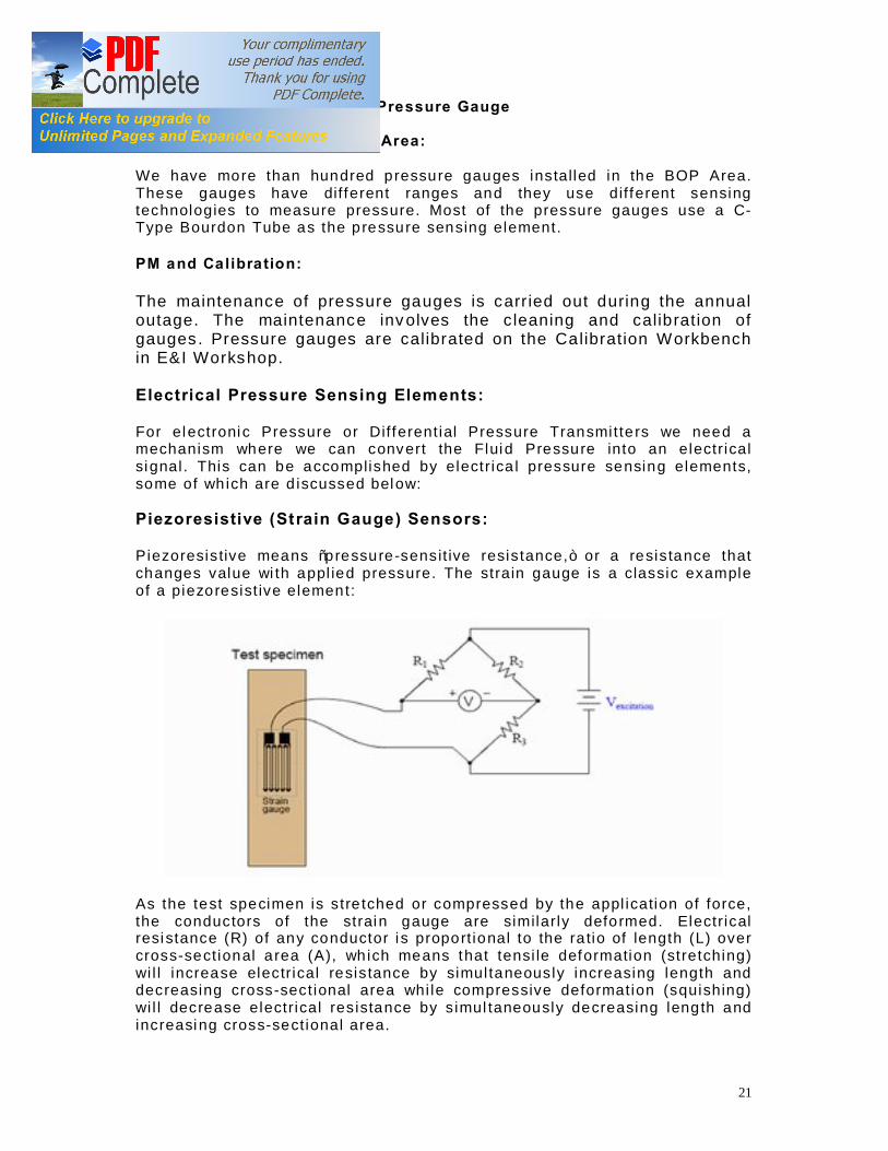
Pressure Gauges in the BOP Area: We have more than hundred p ressure gauges ins ta l led in the BOP Area. These gauges have dif ferent ranges and they use d if ferent sensing technologies to measure pressure. Most of the pressure gauges use a C-Type Bourdon Tube as the p ressure sensing e lement. PM and Ca libra tion: The maintenance of pressure gauges is carr ied out during the annual outage. The maintenance inv olves the c leaning and calib rat ion of gauges . Pressure gauges are calibrated on the Ca librat ion W orkbench in E&I Workshop. Electrical Pressure Sensing Elements: For e lectroni c Pressure or Dif ferent ial Pressure Transmit te rs we need a mechanism where we can convert the Fluid Pressure into an e lectr ica l si gnal . This can be accomplished by e lectr ica l pressure sensing e lements, some of wh ich are d iscussed below: Piezoresistive (St rain Gauge) Sensors: Piezoresis tive means “pressure -sens it ive resis tance,” or a resis tance that changes value wi th appl ied pressure. The stra in gauge is a classic example of a p iezo resist ive e lemen t:
As the test specimen is s tre tched or compressed by the appl ication of force, the conductors of the strain gauge are similar ly defo rmed. Electr ical resi stance (R) of any conductor i s proport ional to the ra tio of length (L) over cross-sect ional a rea (A), wh ich means that tensi le deformation (stretching) wi l l increase elec tr ica l resis tance by simul taneous ly increasing length and decreasing cross-sect ional area whi le compressive deformat ion (squishing) wi l l decrease electr ica l res istance by s imul taneously decreasing leng th and increasing cross-sect ional area.

22
Attaching a s tra in gauge to a diaphragm, resul ts in a device that changes resi stance wi th appl ied p ressure. Pressure forces the diaphragm to deform, which in turn causes the s tra in gauge to change resi stance. By measuring th is change in resistance, we can infer the amount of pressure applied to the d iaphragm. Other common and widely used electric pressure sensing elements are
• Di f ferentia l Capac itance Sensors • Resonant Element Sensor
PRESSURE TRANSMITTERS
Pressure t ransmi t ters are devices designed to measure f lu id pressure and transmi t that informat ion via e lectr ica l signals such as the 4-20 mA ana log standard, or in digi ta l form such as HART. Pressure transmitters in the BOP Area: The p ressure t ransmi t ters i nstal led in the BOP Area a re of the fo l lowing type Manufacturer: Honeywe l l Model : STG94L Sensing Technology: Piezores istive Strain Gauge PM and Ca libra tion: The PM of pressure t ransmi t te rs is carri ed out du ring the annual outage . The fol lowing tools are requi red for the PM and Cal ibrat ion of pressure t ransmi t ters :
• S tandard Toolki t • Dig i ta l Mul t imeter • Dig i ta l Test Pressure Gauge • Honeywel l Smart F ield Communicato r (SFC)
The PM of the p ressure t ransmi t ter involves the fo l lowing s teps
• Obta in a work permi t for the PM of Pressure Transmit ter. • Inform the area operation engineer about the j ob. • Connect the p ressure source to the pressure sensing port of the
pressure t ransmi t ter. • Connect the d ig i ta l mul timeter to the Transmit ter outputs. • A t a 0% pressure inpu t of the current output should me 4 mA. • A t a 100% pressure input the current output should be 20mA. • The p ressure and current values should be checked wi th reference to
the fo l lowing table.
Input Pressure (%) Output Current (mA) 0 04
25 08 50 12 75 16
100 20

23
I f there is any d iscrepancy in the measured values then connect the Honeywel l SFC to the Pressure Transmitte r and enter the Low Range Value (LRV) and Upper Range Value (URV).
PRESSURE SWITCH
Pressure Swi tches a re used for automat ic operat ion and protec tion of equipment. The swi tch actuates when the f lu id pressure reaches the predef ined set-point . Pressure swi tches use Diaphragms, Bel lows and C-Type Bourdon Tube as pressure sensing e lemen ts. Pressure Sw itches in the BOP Area: Many d if ferent types of pressure swi tches are instal led in the BOP Area. Two of the most important pressure swi tches a re d iscussed below: H2 Compressor Inlet Pressure Sw itch (CIP Sw itch): A pressure swi tch is insta l led at the inlet o f the Hydrogen Compressors. I t ac tuates and tr ips the H2 Compressors when the inle t gas p ressure is low. The CIP swi tch uses a bourdon tube as the pressure -sens ing e lement, and a g lass bulb pa rti al ly f i l led wi th mercury as the e lec tri cal swi tch ing element. When appl ied pressure causes the bourdon tube to f lex suff iciently, the g lass bulb ti l ts fa r enough to cause the mercu ry to fa l l agains t a pai r of e lectrodes, thus completi ng an e lectr ical ci rcui t . Advantages o f mercury ti l t swi tches include immuni ty to swi tch con tact degradat ion f rom harmful atmospheres (o i l mist , d i r t , dust , corrosion ) as wel l as safety in explosive atmospheres (since a spark conta ined wi th in a hermet ically sea led g lass bulb cannot touch of f an explosion in the su rrounding atmosphere ). Disadvantages inc lude the possib i l i ty of in termi t tent e lec tr ical con tact resu l ting f rom mechanical v ibrat ion, as well as sensi tivi ty to mounting angle Note: The CIP swi tch has been causing problems for some t ime. When one compressor is running and the othe r starts, the CIP swi tch actuates due to excessive mechan ical vib ra tion of i ts mounting stand . The issue is be ing reso lved and ei ther the mounti ng stand or the swi tch wi l l be replaced. CWP Lube Water Pumps Common Discharge Pressure Sw itch: This is a very cr i t ical swi tch because i ts actua t ion can resul t in the t r ipping of CW P. PM and Ca libra tion: The i r PM is carr ied ou t during the outage and they a re calib rated when requi red. The i r cal ib ra t ion procedure involves the fo l lowing steps
• Apply a pressure source to the sensing port of the pressure swi tch.

24
• Using a dig i tal mu lt ime ter, check whether the swi tch contacts are open or cl ose.
• Gradual l y increase the pressure and mark the po ints where the swi tch ac tuates and where i t resets .
• I f the actuation and deactivation poin ts are d if ferent f rom the des ign se t t ings, use the adjus tment screws to adjust the swi tch.
• Again apply pressure and ask the control room engineer to verif y whethe r the swi tch is behav ing as i t should or no t .
DIFERENTIAL PRESSURE INSTRUMENTS
One of the mos t common, and most useful, pressure measur ing instruments in industry is the dif ferential pressure transmitter . This dev ice senses the d if ference in pressure between two ports and outputs a s ignal representing that pressure in relat ion to a calibrated range. DP instruments use the same sensing elements to measure the dif ference in pressure as the pressure instruments.
Valve Manifold for Differential Pressure Instruments: An important accessory to the dif ferential p ressure transmitter is the three-valve manifo ld. Th is dev ice incorporates three manual valves to isolate and equalize pressure from the process to the transmitter , for maintenance and cal ibra tion purposes.
DP Gauges in the BOP Area: DP gauges are installed on f i l te rs and stra iners to measure the extent of their c logging and choking. The ir PM and calibrat ion procedure is s imilar to tha t of Pressure gauges. DP Switches in the BOP Area: DP Switches are instal led on the following equipment Mixed Bed Pol isher Unit

25
MMF CWP Lube Water Strainer CWP Suction Strainer DMF PM and Calibration: Their PM is done annually dur ing the outage. Their cal ibra tion procedure is s imilar to the Pressure Switch.
LEVEL MEASUREMENT A wide variety o f technologies exist to measure the level of substances in a vessel , each exploi t ing a dif ferent pr incip le of phys ics.
LEVEL GAUGES The level gauge or sigh t-g lass is a very s imple and ef fec tive technology for d i rec t visual ind icati on of process level . In i ts simplest form, a leve l gauge is noth ing more than a c lear tube th rough which process l iquid may be seen. A funct iona l d iagram of a sight-g lass shows how i t v isual ly rep resents the level of l iquid inside a vessel such as a s torage tank:
Level Gauges are instal led on many tanks to prov ide a v isual reading to complement the elec tronic level measurement devices.
LEVEL SWITCHES

26
A level swi tch is used to de tect the f lu id (or sol id) level in a vessel or tank. Level swi tches actuate at p redef ined se t-points to perform some control ac t ion. Many d i f feren t types of Level Swi tches a re be ing used i n the BOP Area . A few of the level swi tches are d iscussed below:
Magnetic Reed Sw itches:
Special types of swi tches a re used i f the l iquid to be measured is a hazardous chemical or i f i t is a t h igh temperature or high pressure. The f igu re below shows a method of swi tching in such cases. Each reed swi tch is normally open. W hen the f loat ing magnet outside the tube comes near the swi tch, i t at t rac ts the magnetic pole piece in the swi tch . Th is action closes the swi tch unt i l the f loa ting magne t moves away. No fo l lower magne t is needed inside the tube .
Magnet ic reed swi tches can be serv iced f rom the top of the tube. These swi tches are no t sealed in the tube, and they never come into contact wi th the l iquid in the tank. Diesel Tank Level Switch: The level swi tches instal led on the Diesel Tank (Fi re Figh ting Pump House) are Magnet ic Reed Swi tches, hav ing a single swi tching point ( low level ). These swi tches do not have the option of adjust ing thei r swi tch ing point . They are ve ry re l iab le and have long operat ional l ives.
Storage Tank Gauge and Level Switch:
The system shown in the f igure is called a s torage-tank gauge. I t has a f loat that rises and fal l s wi th the surface of the l iquid . A perforated tape connected to the f loat passes through the tank top and into the gauge head. A spring moto r keeps the tape taut and exerts a constant tension at the f loat . A sprocket wheel dr ives a shaf t , wh ich in turn drives a coun ter mechanism. The coun ter can be calib ra ted to show the vo lume of water in the tank ins tead of the depth . The s ize and shape of the tank dete rmine how many

27
gal lons (or l i ters, o r cubic feet) of water a re in the tank for every uni t of dep th.
Maintenance:
The most common maintenance problems wi th f loat-ac tuated level gauges of ten occur where the process l iquid contacts the f loa t . The guide cables somet imes b reak or become co rroded, and the tape at tached to the f loat can break or become twisted. A lso, corros ion can cause holes in the f loat . Opening the swi tch and rewinding the reel and tape is a very tedious and t ime consuming activ ity.
Flexible tape and p lumb-bob
This type of Level Swi tch is instal led on the Blowdown Basin and Fi lter Wate r Basin. Capac i tance (Conductiv ity Type Level Swi tch) PM of Level Switches: The PM of Level Swi tches is pe rfo rmed during the annual outage. The PM involves disman tl ing and thorough cleaning of the swi tch. The swi tch is then opera ted and i ts ac tuation and reset po ints a re verif ied .
LEVEL TRANSMITTERS
Level Transmitters are used for continuous measure of the level of a vessel or tank. Level Transmitters operate on many dif ferent pr inc ip les. Two of the most commonly used types are discussed below:

28
Hydrostatic Pressure: A vert ical column of f lu id exerts a pressure due to the column ’s weight . The relat ionship between column he ight and f luid pressure at the bottom of the column is constant for any part icular f lu id (density) regardless of vessel width or shape. This pr inc iple makes it poss ib le to infer the height of l iqu id in a vessel by measur ing the pressure generated at the bottom. Dif ferential pressure transmitters are the most common pressure-sens ing device used in this capacity to infer l iquid leve l within a vessel. In the hypothetica l case of an oi l vessel, the transmitter wou ld connect to the vesse l in this manner (with the high s ide toward the process and the low s ide vented to atmosphere):
Connected as such, the dif ferential pressure transmitter funct ions as a gauge pressure transmitter , responding to hydrostat ic pressure exceeding ambient (atmospher ic) pressure. As l iquid level increases, the hydrostat ic pressure applied to the “high” s ide of the dif ferential pressure transmitter also increases , dr iv ing the transmitter ’s output s igna l higher. In this way the DP Transmitte r can be calib rated to act as a level transmitter by calculat ing the pressure exerted by d if fe rent height of l iquid column. Bubbler Systems: An interest ing variat ion on this theme of d i rect hydrostat ic pressure measurement, d iscussed above, is the use of a purge gas to measure hydrostat i c pressure in a l i quid-contain ing vessel . This e l iminates the need for d i rec t contact of the process l iquid against the pressure-sensing e lement, which can be advantageous if the process l iquid is corrosive. Such systems

29
are of ten call ed bubble tube or d ip tube systems, the former name being appropriately descri pt ive for the way purge gas bubbles out the end of the tube as i t is submerged in process l iquid. A key deta i l of a bubble tube system i s to provide a means of l imi t ing gas f low through the tube, so the purge gas backpressure properly ref lec ts hydrostat ic pressure at the end of the tube wi th no addi tional pressure due to f r ic tional losses of purge f low through the length of the tube. Most bubble tube systems, therefo re , are prov ided wi th some means of moni tor ing purge gas f low, typica l ly wi th a rotameter or wi th a s ightfeed bubbler:
I f the purge gas f low is not too g reat, gas pressure measured anywhere in the tube system downstream of the needle valve wi l l be equal to the hydrostat i c p ressure of the process l iquid at the bottom of the tube where the gas escapes. In o ther words, the purge gas acts to t ransmi t the l iquid ’s hydrostat i c p ressure to some remote poin t where a pressure -sens ing ins trumen t is located . A general ru le-of -thumb is to l imi t purge gas f lo w to the point where you can eas i ly count ind iv idual bubbles exi ting the bubble tube (o r inside the sightfeed bubbler i f one is prov ided on the sys tem).
I t may be noted that in bo th the cases, Bubbler system and Hydrostat ic type Level t ransmi t ters, we a re ac tually measuring the p ressure exerted due to the f l uid he ight and using i t to infer the level of the f lu id. Level Transmitters in BOP Area: Both Bubbler Type and Hydrosta t ic type of level t ransmi t te rs are ins ta l led in the BOP area. In addi tion to these othe r types of Level t ransmi t ters are also ins tal led in the BOP area that are
• Floa t Type Level Transmit ter • Diaphragm Type Level Transmit ter
Make: Honeywel l Model : STD 924 Type: Bubbler PM and Ca libra tion of Level Transmitte rs :

30
The PM of Level Transmit ters is carr ied ou t during the annual ou tage. The PM of pressure t ransmi t te rs is carri ed out du ring the annual outage . The fol lowing tools are requi red for the PM and Cal ibrat ion of pressure t ransmi t ters :
• S tandard Toolki t • Dig i ta l Mul t imeter • Dig i ta l Test Pressure Gauge • Honeywel l Smart F ield Communicato r (SFC)
The PM of the l evel transmi t ter involves the fol lowing s teps
• Obta in a work permi t for the PM of Leve l Transmit ter. • Inform the area operation engineer about the j ob. • Connect the p ressure source to the hydrostat ic p ressure sensing port
of the leve l t ransmi t ter. • Connect the d ig i ta l mul timeter to the t ransmi t ter outputs. • A t a 0% pressure inpu t of the current output should me 4 mA. • A t a 100% pressure input the current output should be 20mA. • The p ressure and current values should be checked wi th reference to
the fo l lowing table.
Input Pressure (%) Output Current (mA) 0 04
25 08 50 12 75 16
100 20 I f there is any d iscrepancy in the measured values then connect the Honeywel l SFC to the Level Transmit ter and enter the Low Range Value (LRV) and Upper Range Value (URV) of hydrosta t ic pressure. Note: The person do ing the calibration must have the data that shows the re la tion between level and pressure for that specif ic device .
Ult rasonic Level Detectors
Operating Princ iple: Another way of measuring l iquid level in vessels is to bounce a t ravel ing wave of f the surface of the l i quid – typ ical ly f rom a loca tion at the top of the vessel – using the t ime-of-f l ight for the waves as an indicator of d istance, and therefo re an ind icato r of l iquid height inside the vessel . This form of measurement i s cal led Time Domain Ref lec tometry .
Ultrasonic Waves:

31
Ultrasonic sound waves wi th f requenc ies of 1 to 5 megahertz (MHz) can be used to detect l iquid or solid levels. Basically, u l t rasoni c waves are sound waves, but are at h igher f requencies than can be detected by the human ear (usually up to 20 ki lohertz maximum).
The most common kind of u l t rasonic t ransducer cons ists of a piezoelec tr ic crysta l (such as quartz). W hen a vol tage i s applied to the p lates , the p iezoelectr ic c rysta l expands or con tracts. I f the vol tage is al ternating at an u l t rasonic f requency, the crysta l expands and contracts a t the same ul t rasonic f requency. The crys ta l vibrates, and these v ibrations can be t ransferred to a d iaphragm to produce ul t rasonic sound waves.
Ultrasonic Level Instruments: Ul t rasonic level ins truments measure the dis tance from the t ransmi t ter ( located at some high point) to the surface of a process materia l located further below. The t ime-o f-f l i ght fo r a sound pulse indicates th i s d istance, and is in terpreted by the t ransmi t ter e lec tronics as process level . These transmi t ters may ou tput a s ignal corresponding e i ther to the fu l lness of the vessel (f i l lage ) or the amoun t of empty space remaining at the top of a vessel (ullage ) .
Ul lage is the “na tural ” mode of measurement fo r th is so rt of level instrument, because the sound wave ’s time-of -f l ight is a d i rec t function of how much empty space exis ts between the l i quid surface and the top of the vessel . Tota l tank height wi l l always be the sum of f i l lage and ul lage, though. If the u l t rasonic level t ransmit ter is programmed wi th the vessel ’s to tal heigh t, i t may calcula te f i l lage via simple subtracti on:
Fi l lage = Total height − Ul lage
Ultrasonic Level Devices at BOP: Two types of u l t rasonic level devices are being used a t the BOP a rea
1. Ul t rasonic Level Swi tch 2. Ul t rasonic Level Transmit ter

32
Ultrasonic Level Switch: Manufacturer: S iemens Mi l i t roni cs Model : POINTEK ULS200 This swi tch is to be insta l led on the ne w Sodium Hypochlori te Tank. Thi s swi tch is p rogrammed using the Siemens Infrared Hand Programmer . Ultrasonic Level Transmitters: Manufacturer: S iemens Mi l i t roni cs Model : SITRANS Probe LU Manufacturer: Endress & Hauser Model : Prosonic FMU 860 Programming (Calibrating) a Siemens Ultrasonic Level Device: The Mi l i t ron ics u l t rasonic level t ransmi tter or swi tch is programmed by the Siemens Hand Programmer. To calibrate the level t ransmi t te r we need to enter the exact values of d if fe rent parameters such as Tank Heigh t and Maximum Liquid Height in the dev ice . Programming (Calibrating) a Prosonic FMU 860 Level Transmitter: The Prosonic FMU 860 ul t rasonic level t ransmi t ter is prog rammed by using the buttons and d isplay g iven on the t ransmi t ter body. To calib ra te the level t ransmi t ter we need to enter the exact values of d if fe rent parameters such as Tank Height and Maximum Liquid He ight in the dev ice. Note: When we insta lled SITRANS Probe LU at RO 4% Acid Tank (PAKGEN) the opera tion pe rsonnel complained that the response of the Level Transmit ter was very s low. To increase the response t ime, we changed the value of parameter P003 [Response Time], f rom slow to medium. This rect if ied the problem. Mounting Instructions:
1 . I t should be ensured that the sound pa th rema ins pe rpendicular to the material being sensed.
2. Ideal ly, mount SITRANS Probe LU so that the face of the t ransducer is
at least 300 mm (1 f t ) above the highest ant ici pated l evel .
Troubleshooting:
I f proper communication is no t being estab lished wi th the device
33
1. Check the fol lowing : • There is power at the uni t • The LCD shows the re levan t data • The device can be programmed us ing the hand p rogrammer
2. Verif y that the wi r ing connecti ons a re correc t .
In case of any o ther error or faul t , note the faul t code and consul t the dev ice ins truction manual for furthe r action .
FLOW MEASUREMENT The measurement of f lu id f low is very important in process contro l . Flow meters te l l us about the tota l f lu id being consumed in the system and at d if fe rent poin ts.
FLOW SWITCHES
A f low switch is detec ts the f low o f some f luid through a p ipe. Flow switches often use “paddles ” as the f low-sensing element, the motion o f wh ich actuates one or more swi tch contacts . F low switches are used main ly for the pro tect ion of pumps. The y indicate the f low of Lube (and coo ling) water. If there is not suff ic ient f low of lube water the pump (e.g. CW P) wi l l not s tar t . The PM of f low swi tches is done annually.
FLOW TRANSMITTERS
Flow Transmitters are installed at var ious points in the BOP area to prov ide a continuous data regarding the f low ra te and tota l f low (volume) of the process f luid. These transmitters prov ide the f low data to the DCS or PLC depending on the control loop o f which they are a part. There are two types of F low measurement dev ices being currently used in the BOP area
• Turbine Type Flow Transmitters • DP Type Flow Transmitters
Turbine Type Flow Transmitters: Turbine type f low meters are volumetr ic-f low measurement devices. They infe r the f low rate of the f luid f rom the f lu id ve loci ty. The f igure below shows a turb ine type f low meter. I ts opera t ion is described below

34
Cutaw ay Image of a Turbine Type Flow Meter
Fluid enters the meter f rom lef t , pass ing through the f low straightener . The stra ightener dampens the tu rbulence in the f lu id. The f lu id then str ikes the rotor smoothly, causing i t to spin. The rate at which the rotor spins, somet imes referred to as rotat ional ve loci ty , i s d i rectly proport ional to the veloci ty of the f lui d pass ing through the meter. As the roto r spins , i ts blades cause a pulsa t ing elec tri cal signal to be produced in the pickup uni t . The pickup uni t is mounted in l ine wi th the rotor. Each t ime a blade passes the head of the p ickup uni t , i ts presence is sensed and a vol tage is produced . As the b lade moves past the pickup head, the vo l tage decreases unt i l another blade moves in to posi tion.
• The veloc ity o f f luid f lowing through the meter is p roport ional to volumetri c f low rate.
• The ro tationa l velocity of the rotor is proport ional to f lu id veloci ty. • The frequency of the e lec tr ical signa l produced by the magne t ic pickup
uni t is proportional to the rotor ’s speed (rpm). In thi s way by comput ing the f requency of the electrical s ignal p roduced by the magnetic p ickup uni t we can infe r the volumetri c f low rate of the f lu id . PM of a T urbine Type Flow Meter: The PM of Turbine Type f low transmi t ters is done during the annual outage. The PM of the tu rb ine type transmi tter involves the fo l lowing steps:
• Apply for Live work Permi t • Iso late the pipe on which FT is ins tal led • Note the posi tion of the turbine meter before tak ing i t ou t of the p ipe • Open the connector connecting the Turbine Flow Meter to the p ipe and
take out the turbine e lement f rom the pipe and immediately close the isolating valve.
• Clean the Turbine Element • Rotate the element and see whether the Flow Mete r shows accura te
reading; the f l ow mete r should show zero when the turbine element stops rotati ng
• Insert the turb ine e lement in the pipe in the same pos it ion as befo re . • Screw the Flow Mete r i n to proper p lace

35
Note: The angle of the e lement should not be changed or i t wi l l resul t in inaccura te reading. DP Type Flow Meters: The relat ionsh ip between the Delta P and Flow is non l inear. F low is direct ly proport iona l to the square root of the dif ference in pressure.
Q = k√ ((P1-P 2)/ρ)
PM and Calibration of DP Type Flow Transmitters: The PM of Flow transmi t te rs is carr ied ou t during the annual ou tage. The fo l lowing tools a re requi red for the cal ibrat ion of DP Type f low transmi t ters Standard Toolki t Pressure Source Mul t ime ter Fol low the fol lo wing steps to calibrate a DP Type F low Transmit ter.
• Obta in a work permi t for the PM of Flow Meter. • Inform the area operation engineer about the j ob. • Close both the High Pressure Side and Low Pressure s ide valves. • Open the equa lizing valve. • Close the equalizing valve af ter some time and connect the p ressure
source to the high pressure side. • Connect the d ig i ta l mul timeter to the Transmit ter outputs.

36
• A t a minimum pressure i nput of 0mm H20 the current outpu t should me 4 mA.
• A t a maximum pressure input of 3000mm H2O the current ou tput should be 20mA.
• The p ressure and current values should be checked wi th reference to the fo l lowing table.
Percentage
% DP
(mmH20) Current
(mA) 0 0 4 25 750 12 50 1500 15.314 75 2250 17.86 100 3000 20
I f there i s a d iscrepancy between the table values and the measured values then :
• Readjust the Upper Range Value (URV) and Low Range Value (LRV) of the t ransmi t ter by us ing the Honeyw ell SFC or HART Communicator .
• Close the cover of the t ransmi t ter af ter reconnecting the supply and signal wi res .
The values g iven above have been calculated by us ing the formula that re lates Flow Rate to Dif fe rent ia l Pressure.
Q = k√ ( (P1-P2) /ρ) Note: The 0-3000 mm H20 pressure range has been taken as an example, the actual range of the Flow Transmit te r may be d if feren t.
TEMNPERATURE MEASUREMENT The measurement of temperature of d if ferent equipments and processes is essenti al for process control . There are rela tively few temperature t ransmi t ters and sensors insta l led in the BOP Area. However RTDs have been ins tal led to de tect the winding temperature of the moto rs of CW P. RTDs are a l so used to measure the tempera ture of Cooling Tower Fans. RTD: The elec tr ical resis tance of certa in metals changes as the ambient temperature changes. This characteristic is the basis fo r a temperature-measuring i nstrument called an RTD, o r Resis tance-Temperature De tector. The RTD is a kind of t ransducer. RTDs convert temperatu re changes to vol tage signa ls (usual ly mi l l vol ts, or mV) by measuring resistance. The materials used in the RTD must be extremely pure, of uniform qual i ty, stable wi th in a specif ic temperature range, and able to give rep roducible resi stance-temperature readings. Only a few metals have these propert i es—for example, p latinum, copper, and nickel . The re lat ionship between resi stance and tempera ture is l i near for a certa in range of temperatures. The

37
rate at which the resi stance increases as temperature increases depends on the spec if ic characte ristics of the metal . Wheatstone Bridge Circuits: The e lectr ical ci rcui t commonly used wi th a p lat inum RTD is referred to as a Wheatstone bridge . The bridge converts the RTD ’s change in resis tance to a vol tage outpu t. This ci rcui t uses four separa te e lectr ica l res istors , one of which is the RTD. The bridge is ini t ia l ly balanced , wi th vol tage output equal to zero , because al l four resistors are equal . As the resistance of the RTD changes, due to a temperature change, the bridge becomes unbalanced, resu l ting in a vol tage output othe r than zero.
Resistance of RTD changin g due to Tempe rature
PM and Ca libra tion of Temperature Sensors:
The PM of RTDs is carr ied out during the annual ou tage. A Temperatu re Cal ibra tor (S imulato r) is used to ca librate the RTDs.
Note:
The wir ing str ips of the RTDs insta lled on the CWP (Uni t 2) were changed during PakGen outage. The RTDs were ca librated and the i r readings were ve ri f ied f rom the Control Room.
ANALYTICAL MEASUREMENT
pH & ORP Sensors
pH: A measure of the ac idity of a process liquid as determined by the number of hydrogen ions; the negative common logar ithm of the hydrogen ion concentrat ion in an aqueous solu tion. The pH value of an aqueous (water containing) l iquid is an indicat ion of pos it ive hydrogen ion (H+) act iv ity. Read ings of pH in non-aqueous l iquids are not measures of hydrogen ion act iv ity, but are useful in specif ic s ituat ions. The molecules that ma ke up a l iquid,

38
whether water alone or water with another chemical dissolved in it , can be part ial ly b roken down into smal ler part ic les referred to as ions . Some of the molecules in water (H2O break down into two dif ferent kinds of ions, H+ (hydrogen) and OH- (hydroxyl) . ORP (Oxidation-Reduction Potential) ORP is a measure o f the rat io of ions that ox idize to those that reduce other chemicals ; the value (on a logarithmic scale) in mil l volts (mV) of a l iquid ’s ox idat ion or reduction potential. Temperature and pH: Temperature has a s ignif icant effect on pH. Pure water has a pH of 7 only at 25°C (77°F), wh ich is referred to as the s tandard temperature. The dissociat ion constant changes with changes in temperature. This causes the rat io of H+ to OH- ions, and thus the pH value, to change as we ll. pH Analyzers normal ly inc lude a tempera ture detector and are capable of calculat ing the pH, by means of a temperature correct ion factor, as if the temperature actual ly were 25°C.
Effect of Temperature on pH value
Temperature, 0C Neutral pH 0 7.47
25 7.00 50 6.63 75 6.35
100 6.13
Measuring pH and ORP
pH and ORP Reference Elect rodes
A pH probe is made up of two separate electrodes, as is an ORP probe. The reference e lectrode i s the same for both pH and ORP probes, but the measure ment e lectrodes are di f fe rent. The re ference e lectrode i s designed to provide a constant vol tage potent ial despi te changes in pH or temperature. This elec trode is used to moni to r any change in the tota l l iquid potent ia l .
39
The lead wire is in an inner tube that conta ins si lver metal and si lver ch loride paste. This paste is in contact wi th a sa turated solut ion of potassium chloride (KCI), which ac ts as an electr ica l br idge to the solu t ion being measured. The potentia l of the refe rence electrode depends on temperature and on the KCI concentrat ion.
The KCl slowly migrates f rom the refe rence electrode to the solution being measured by means of a l iquid junct ion cons isting of a porous ceramic material near the bottom of the e lectrode. Crysta ls of sol id KCI i n the bottom of the electrode ensure that the solu tion stays saturated. A porta l is prov ided for repleni shment of the KCI, and a rubber sleeve protec ts the portal f rom contamination .
pH Measurement Electrodes
The pH measurement e lec trode produces a potent ia l , which re la tes d i rec tly to the solut ion in wh ich i t is submerged. Measurement of the poten tia l requi res a current through a very h igh impedance ampl if ier and back to the process l iquid. E lec tr ical connection of the measuring ci rcui t to the l iquid is through a l iquid junction that is part of the re fe rence elec trode.
The pH measurement elec trode has a th in-wa l led glass bulb f i l led wi th a l iquid of known PH, usuall y potassium chloride (KCl ) . A silver-si lver chloride e lectrode is immersed in the l iquid. The hydrogen ions on the inside of the e lectrode are of a dif ferent concentrat ion than the hydrogen ions on the outside. These ions want to reach equil ibr ium by mig ra t ing through the g lass wa l l of the e lectrode unt i l the concen tra t ions are the same.
This migra tion is p reven ted by the glass, and thus a po tential i s established. A potent ia l di ffe rence across the th in bulb wi l l occu r when the H+ act iv ity inside the e lec trode i s dif fe rent f rom the H+ act iv i ty in the l iquid to be measured. Because glass is an insulator, the bulb wal l must be ve ry th in to permi t accurate vol tage readings.
The pH measurement electrode (which is usual ly at tached to a high-impedance vol tme ter) reacts to any change in vol tage and reports i t as a pH reading. The pH measurement elec trode has a watert igh t seal at the top to keep out any l iquid or moisture that could af fect the p robe ’s operat ion.
ORP Measurement Electrode
The ORP measurement electrode i s s imp ly a p latinum wire exposed at i ts bot tom end to the process l iquid. The ORP refe rence electrode is identical to the pH reference electrode. The ORP measurement elec trode reacts to va riations i n vol tage. Vol tage va riations caused by va riations i n the activ i ty of the oxidi zing and reducing ions in the process l iquid are ampl i f ied and d isplayed as the ORP of the l iquid.
pH Analyzers at BOP: At AES LalPir we have the fol lowing pH & ORP Sensors installed in the BOP Area.
40
Manufacturer: Yokogawa Model: EXA PH202 Input: 24V DC Output: 4~20 mA Manufacturer: DKK Model: HDM -135 Input: 24V DC Output: 4~20 mA
Preventive Maintenance:
The PM of pH meters is carr ied out on a for tnight ly bas is . The pH probe is c leaned and the pH meter is calib rated as part of the PM activ ity. The calibrat ion process requires the following solut ions and tools
• pH 4.01 solut ion • pH 10.01 solut ion • pH 7.01 solut ion • KCL solut ion • Clean (Demineralized) W ater bottle • Tissue Paper
Calibration Procedure:
1. Obta in a Live work permit for the PM of pH meter.
2. Inform the area operat ion engineer,
3. Put the pH meter on Standby. [The pH reading in CCR wi l l remain
f ixed]
4. Isolate the pH meter.
5. Care fu lly take out the pH probe from the pipe.
6. Check whether the KCL solu tion is present in the top of electrode
or not.
7. If KCL solut ion is not present or dimin ished, ref i l l i t .
8. Check whether the pH meter is configured for a 2-po int
calibrat ion (pH 4 & pH 10).
9. Rinse the t ip of electrode with Demineralized water.
10. Clean the t ip of the electrode with a t issue paper.
11. Press the Calibrat ion Button on the pH meter.

41
12. Dip the pH electrode in a pH 4.0 buffer solut ion and gently
s t ir the solut ion with the elec trode.
13. When the disp lay shows NEXT, press the Calibrat ion button
again.
14. Qu ickly r inse the electrode wi th Demineralized water and
dry it with a t issue.
15. Dip the electrode in a pH 10.01 buffer solut ion and gently
s t ir the solut ion t i l l the display becomes normal again.
16. Again r inse the elec trode with Demineralized water and dry
it .
17. Put the probe back into the pipe.
18. Remove the isolat ion and open the valve to allow the pH
meter to read the actual pH value.
19. When the pH value has s tabil ized, put the pH meter on
normal mode.
Conductivity
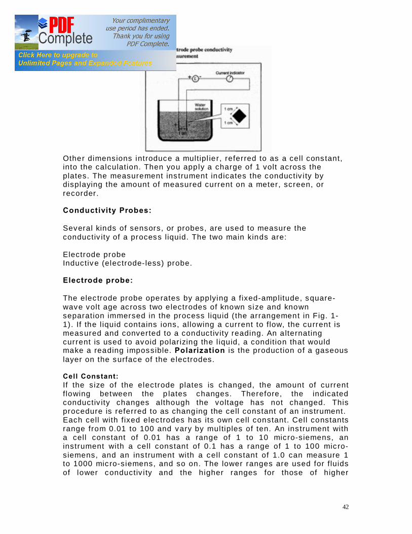
The conduc tiv ity of a substance is the measure of its ab il i ty to conduct electr ic current. The conductiv i ty o f a substance is the conductance of a unit length and un it c ross-sect ional area of tha t substance. The abil i ty to measure a process l iquid ’s conductiv ity is essentia l in controll ing a process system. Conductivity Measurement: To measure conductiv ity in a l iquid, you insert two plates in the l iquid. As shown in the Figure, these plates (called electrodes) are each 1 cm square. The p lates must be parallel to each other and separa ted from each other by 1 cm for conductiv ity to be equal to res is t iv ity.
42
Other dimensions introduce a mult ipl ie r , referred to as a cell cons tant, into the calculat ion. Then you app ly a charge of 1 volt across the plates. The measurement ins trument indicates the conductiv i ty by displaying the amount of measured current on a meter, screen, or recorder. Conductivity Probes: Several kinds of sensors, or probes, are used to measure the conductiv ity of a process l iquid. The two main kinds are: Electrode probe Inductiv e (electrode- less) probe. Electrode probe: The elec trode probe operates by applying a f ixed-amplitude, square-wave volt age ac ross two e lectrodes of known s ize and known separat ion immersed in the process l iquid ( the arrangement in F ig. 1-1) . If the l iquid contains ions, allowing a current to f low, the current is measured and converted to a conductiv ity reading. An a lternating current is used to avoid polar izing the l iquid, a condit ion that would make a reading impossible. Polarization is the production o f a gaseous layer on the surface of the e lectrodes. Cell Constant: If the s ize of the electrode plates is changed, the amount of current f lowing between the p lates changes. Therefore, the indicated conductiv ity changes although the voltage has not changed. This procedure is referred to as chang ing the cell constant of an instrument. Each cell with f ixed elec trodes has its own cell constant. Cell constants range from 0.01 to 100 and vary by mul tiples of ten. An ins trument with a cell constant of 0.01 has a range of 1 to 10 micro-s iemens, an instrument with a cell constant of 0.1 has a range of 1 to 100 mic ro-s iemens, and an ins trument with a cell constant of 1.0 can measure 1 to 1000 mic ro-s iemens, and so on. The lower ranges are used for f lu ids of lower conductiv i ty and the higher ranges for those of higher

43
conductiv ity. By changing the cell cons tant, you can adapt an instrument fo r the range of conductiv ity of the l iqu id you are measur ing. A conductiv ity probe must be mounted so that it is in direct contact with the process l iquid at all t imes. Each probe is connected to an indicator or transmitter by a 3 to 4 wire cable . The ex tra wire(s) are used for temperature compensation. Inductive probes: The inductive magnetic f ie ld probe, also referred to as an electrode-less probe, operates on a dif ferent pr inc iple from the elec trode probe. The inductive probe is made up of two completely enc losed e lectr ical coils . Dur ing operat ion , the probe is ent irely immersed in the process l iquid . The probe is enc losed in a corros ion- res is tant coating. The instrument sends an alternating current through the pr imary coil. This current creates an alternating magnetic f ie ld that induces an alternating cur rent in the pickup coil. The conductiv ity of the process l iquid affects the magnetic coupling between the coi ls . The induced current in the pickup coil is d irec t ly proport ional to the conduc tiv ity of the l iquid . No d irec t contact is necessary between the coi ls and the solut ion, thus reducing potentia l maintenance problems. This system normally transmits a 4 to 20 mA dc s ignal that is proport ional to the measured conductiv ity. To change the cell cons tant, you change the probe. Each probe is connected to an indicator- transmitter by a cable with at least s ix wires. Two pairs of wires are connected to the coils . The remaining wires are used for temperature compensation. The indicator- transmitter sends a current to the inductive probe. It then reads the pickup coil current, converts that current to conduc tiv ity, and disp lays a reading of the measurement. The elec trode-less probe is corros ion and eros ion res is tant, bu t requires higher conduc tiv it ies and is more complex and cos t ly. Conductivity Meters in the BOP Area: We are us ing the Conductiv ity Meters from Yokogawa and DKK. The PM of the conductiv ity meters is done annually and they are calibrated when required.
HYDROGEN GAS MONITOR
The Hydrogen generat ion p lant is a very cr it ical area of the plant. H 2 gas can form explos ive mixture and there always a hazard of exp los ion in case of H2 gas leakage. To detect the leakage of Hydrogen in the Hydrogen Build ing we have installed H2 gas detect ion system tha t cons is ts of the following parts :

44
Hydrogen Gas Leak Detector (Sensor) Beacon 410 Gas Moni tor Beacon 410 Gas Monitor: The Beacon 410 is a h ighly conf i gurable , microprocessor-based, f lexible and easy to use 4 channel gas monito r. I t simul taneous ly d isplays the gas type, readings, and s tatus for 4 channels of gas detection . I t is connected to the H2 sensor and i t converts thei r 4~20 mA ana log signal in to a ppm reading that i s shown on the d isplay. Each channel has 3 ful ly conf igurable a larm po ints. A buil t - in audible a larm ale rts you to a la rm condi tions. Each channel also has 2 dedicated fu l ly conf igurable re lays and the re is a bank of common re lays as wel l . The common re lays can opt ional ly be conf igured as addi tional channel re lays a llowing up to 3 alarm re lays per channe l .

45
Chapter 3: FINAL CONTROL ELEMENTS
CONTROL VALVES
Control valves a re valves used to control condi tions such as f low, pressure, temperature, and l iquid level by fu l ly o r part ial ly opening or c losing in response to signals received f rom contro l lers. The control va lve manipu lates a f l owing f luid , such as gas, s team, wate r, or chemical compounds, to compensate for the load dis turbance and keep the regulated process variable as close as possib le to the desi red set point . Contro l valves are comprised of two major pa rts : the valve body , wh ich contains al l the mechanical components necessary to inf luence f luid f low; and the valve ac tuator, which p rovides the mechanical power necessary to move the components wi th in the valve body.
Control Va lve w ith a Positioner & I /P Converter
The purpose of a con tro l va lve actuator is to provide the motive force to opera te a valve mechanism. Both sl id ing-stem and rotary contro l valves enjoy the same selec tion of actuators: pneumatic , hyd raul ic , e lectr ic motor, and hand (manual ). Pneumatic actua tors use a i r p ressure pushing against ei ther a f lexib le d iaphragm or a p is ton to move a valve mechanism. The ai r pressure requi red

46
to motivate a pneumatic actuator may come di rec t ly f rom the ou tput of a pneumatic process con tro l ler, or f rom a s ignal transducer (or converte r) t rans lating an electr ical signal in to an ai r pressure signal . Such transducers are commonly kno wn as I /P or “ I to P” converte rs, since they typica l ly t rans late an e lectr ic current signal ( I ) of 4 to 20 mA DC in to an ai r pressure signal (P) of 3 to 15 PSI. I /P Converters: I /P Converters a re a lso known as Elec tro -Pneumatic Transducers. The transducer receives a 4 to 20 mA DC input signal and transmi ts a proport ional 0.2 to 1 .0 bar (3 to 15 psig) pneumatic output p ressure to a f inal contro l element (Contro l Valve). Valve Positioner: A Posi t ioner is a mo t ion-control dev ice designed to actively compare stem pos i tion agains t the control signal , adjusting pressure to the ac tuator d iaphragm or pis ton unt i l the correc t stem posi tion is reached. In other words, a pos i tion is a secondary con tro l sys tem13 un to i tself , act ing wi th in i ts l imi ts to main tain valve stem posi tion in close correspondence to the contro l signal ’s command:
Pos i tioners essential ly act as contro l sys tems wi th in themselves: the valve ’s stem pos i tion is the p rocess va riable (PV), the command signal to the pos i tioner is the setpoint (SP), and the posi tioner ’s signal to the valve ac tuator is the manipula ted variab le (MV) or output. Thus, when a process contro l ler sends a command signal to a valve equipped wi th a posi tioner, the pos i tioner receives that command signal and does i ts best to ensure the valve s tem posi t ion fo l lows a long . Control Va lves at BOP: At AES LalPir the I&C Departmen t is responsible for the maintenance of the va lve actuator and the MMD Department is responsible fo r the main tenance of valve body . Nearly a l l the Control Valves (Throt tl ing Action) in the BOP area pneumatically actuated wi th a Hand-Jack fo r manual actuation . The control valves in the BOP a rea have been prov ided by the fol lowing manufacturers:

47
• FISHER • COPES VULCAN
o Series 9500 , Mode l 9501 o Pneumatic , Diaphragm Actuated o Di rect o r Reverse Acting
The PM of control va lves is carr ied out during outage. The fol lowing spare parts must be readi ly avai lable
• Diaphragm • Valve Posi t ioner (Spare Parts ) • I /P Converte r (Spare) • Ins trumen t Ai r Tubing • Proper Fi t ti ngs • Nuts and Bol ts
PM of Control Valve: The fo l lowing tools a re requi red for the maintenance of Control Valves
• Comp lete Toolkit • Mi l l iampere Current Source • Dig i ta l Test Pressure Gauge
The Prevent ive Maintenance of the Contro l Va lve involves the fol lowing steps:
• Obta in the work permi t • Ask the Contro l Room operator to operate the Va lve and observe i ts
opera tion • I f the valve is no t operating properl y, realign the valve stem and
ca librate the I /P converter and Valve Posit ioner • To calibrate the I /P converter give a 4 mA cu rren t signal at i ts input
and observe i ts output p ressure wi th the Dig i ta l Test Pressure Gauge; the p ressure should be 3 psig
• Adjus t the current to 20mA; the p ressure should now be 15 ps ig • Repea t the fo l lowing steps un ti l the device meets the accuracy
requi rements • I f the I /P converte r is ok and the valve is s t i l l no t working p roperly
open the casing of the Valve Pos i tione r • Clean the Valve Posi ti oner • Adjus t the zero and span set t ings of the valve posi t ione r • Operate and observe the con tro l valve • In case the problem is not resolved by calibration, check to see
whethe r any part requi res replacement; and replace i t • Clean the control va lve
ON-OFF VALVES
48
On-Off Valves are s imil ar to control va lves but they are not used for modulat ing contro l , they a re only used for on -o f f contro l i .e . an On-Of f valve wi l l ei ther be open or close. On-Off Valves in the BOP Area: The On-Of f va lves in the BOP area have been p rov ided by the fo l lowing two manufacturers
• Keystone • ITT
PM of the On-Off Valves: The PM of these valves is done on an annual basis . The fol lowing parts are requi red for the maintenance of these va lves
• S tandard Toolki t • Valve Sealing Ki t • Rubber seali ng O-rings of d if ferent s tandard s izes
The actuators of these valves a re opened and cleaned. The damaged seals are replaced and the valve is c leaned and grease is appli ed to the mov ing parts .
SOLENOID VALVES (SOVs)
A solenoid valve is an e lectromechanical va lve fo r use wi th l iquid or gas. The valve is contro l led by an electr ic current through a solenoid coil . Solenoid valves may have two o r more ports: in the case of a two-port va lve the f low is swi tched on or of f ; in the case of a three-port va lve, the outf low is swi tched between the two out let po rts. Mu l t iple solenoid valves can be placed together on a manifold.
In the BOP area SOVs are most l y used to control the f low of a i r to On-Of f va lves. The PM of these valves i s ca rr ied out du ri ng the annual outage.
STROKE CONTROLLERS
Stroke Control lers a re dev ices that are used to control the f low rate of metering pumps. Stroke Contro llers are used wi th Posi tive Displacement pumps that are used for chemical dosing . Stroke control le rs con tro l the strokes and hence the dosing rate of the Chemical Dos ing Pump. At AES LalPi r we have four d if ferent types o f Stroke Contro ll ers ins tal led in the BOP area.
• NEPTUNE Stroke Control lers • PULSAMATIC Stroke Con tro llers • PULSAFEEDER Stroke Controllers

49
• OBL Stroke Contro l lers Neptune Stroke Controller: The Nep tune EC 5000 & EC 6000 Electroni c Stroke Con tro ller are bi -d i rec tiona l , AC powered, d ig i ta l elec tronic l i near ac tuators wi th buil t - in servo amplif ie rs . The Stroke Con tro ller is mounted on a Neptune 500 series or 600 se ri es hyd raul ic diaphragm type chemical me tering pump. Pump capaci ty is contro l led by the contro l ler 's brushless stepper motor which is di rec t ly connected to the pump con tro l rod. OBL are the l atest s troke contro l le rs that have been instal led on RO Acid Feed pumps in LalPi r and PakGen. PM of Stroke Controllers: The PM of stroke control lers is ca rried out on an annual basis during the annual ou tage. The fo l lowing tools and spare parts must be on hand fo r the maintenance of stroke control lers
• S tandard Toolki t • Cotton Cloth • Mi l l i -Ampere Current Source • Ins truct ion Manual • E lec tronic Card (Spare )
The fo l lowing steps are fol lowed during the maintenance of Stroke Contro ll ers
• Work Permi t is obtained. • Operat ion engineer is i nformed abou t the job . • The cover of the stroke control ler is opened. • The electr ica l connect ions of the s troke contro l le r a re removed and the
wi res a re properly tagged. • The s troke contro l ler is separated f rom the pump and b rought to the
workshop for overhaul ing. • The s troke contro l ler is di sassembled. • The s troke contro l ler is di l igentl y cleaned and i ts mov ing parts are
properly lub ri cated . • The s troke contro l ler is reassembled and i ts elec tr ic wi res a re
reconnected. • The s troke contro l ler is cal ibrated . • For cal ibrat ion fo l low the procedure g iven in the ins truction manual . • A f ter ca libration connect the stroke contro l ler to the metering pump
and test the stroke contro l ler by g iving a simulated 4~20 mA cu rren t si gnal a t i ts input.
• I f the s troke control ler is operating as per design then rejo in the s troke contro l ler to the pump and remake the e lectr ica l connect ions.
Safety Note:

50
I f we have to go and work on a stroke contro l ler whi le the plant is running the fo l lowing must be kept in mind:
• S troke control lers are chemical dosing pumps. • We should read the MSDS of the chemical before working on the
stroke control ler. • I f possib le, the s troke control le r should be taken ou t of serv ice fo r
maintenance. • We must be wearing face shie ld and al l o ther requi red PPEs.

51
Chapter 4: CONTROL SYSTEM
DCS
All the majo r pumps and drives in the BOP area a re being contro l led by the DCS. For instance
• CWP • Canal W ater Pumps • Clarif ier Supply Pumps • S torm W ater Pumps • Demineral ized Wate r Pumps Service Water Pumps
In addi tion to th is the Fi re system indi cations and tank level indications are a lso avai lable in the CCR.
WATER TREATMENT PLC
The Demineralizat ion system and the RO System are controlled by the Water Treatment PLC system. The PLC is located in the W ater Treatment MCC. Manufacturer: The PLC system has been prov ided by ALLEN-BRADLEY. Processors: The processor instal led in the Water Treatment PLC is PLC 5/30 Cat # 1785 L30 B/E. The sys tem cons is ts of redundant CPUs. One of the CPU is serv ice and the other is s tandby. Both the processors are mounted in a 4 s lot chassis . Processor Specif ications: Model: PLC 5/30 Cat # 1785 L30 B/E User Memory W ords Max: 32K Memory Types: Battery-backed s ta tic RAM, EEPROM program backup Total I/O Max:1024 Analog I/O Max: 1024 I/O Scan Time per Rack: 10 ms @ 57.6 kbi t /s Power Supply:

52
Each CPU has its own independent Power Supp ly module. The power supply module is prov ided external AC power by a transformer mounted ins ide the PLC Cabinet. Specif ication: Input Voltage: 220 V AC Input Voltage Range: 194-264 V AC Real Input Power Max : 56W Apparent Input Power Max : 89 VA Transformer Load Max : 140 VA Backup Communication Module: Also mounted in the chassis is a Backup Communicat ion Module (BCM) Cat # 1785-BCM C. The BCMs of both the processors communicate with each other; in case the serv ice processor goes off l ine due to any reason the sys tem wi l l not be disrupted and the s tandby processor wil l take ov er. Remote I/O Adapter Module: The I/O Modules are installed in a 16 s lot chassis that also has a Remote I/O Adapter Module. The I/Os from the f ield are connected to a fused wir ing arm. The fused wir ing arm prov ides pro tect ion to the I/O modules in case of short c ircui ting in the f ield. The Remote I/O Adapter Modules communicate direct ly with the CPUs. Communication with Operator Station: The process data is sent from the CPUs to the d isplay s tat ions on a DH+ communica tion l ink at a speed of 57.6Kbps . The DH+ l ink is instal led in the form of a r ing and all the CPUs are communica ting with the r ing i .e . the data from any PLC processor can be disp layed on any computer in the BOP Control Room (LalPir or PakGen). Operator Stations: The process parameters are displayed on two computers (on each unit) placed in the BOP Contro l room. The software used for superv isory control is RSVIEW 32 . The software al lows operat ion engineers to v iew the process parameters in real t ime, change any set points or control (s tar t or s top) any equipment. The operator s tat ions are password protected and only the relevant operat ion engineers can access it . Troubleshooting: I&C main tenance engineers can troubleshoot the PLC system by us ing RSLogix 5. The troubleshooting act iv it ies may inc lude but are not l imi ted to :

53
• Programming ( to incorporate changes in process )
o To add a new process loop. To change the logic of a process etc
• Forc ing (an input) dur ing main tenance or test ing
• P ID Loop Tun ing
o To manipu late the parameters of a PID control loop to obtain the optimum results
Hydrogen Generation PLC System
The Hydrogen Generat ion Plant is controlled by a PLC system. The PLC system basically controls the Rectif ier and the two H2 Compressors, and it is a SLC-500 sys tem. The PLC at the H2 Generat ion P lant was recently upgraded dur ing the PakGen Outage.
• Hot Work Permit Obta ined • L ive W ork Permit Obta ined • F ire Man arranged (along with F ire Extinguisher) • H2 Generat ion Plant was isolated . • Connection drawing of the OMRON PLC v erif ied in the f ield. • Each and ev ery I/O and power supply wire was compared with the
drawing and found ok. • The power supply wires connected to the OMRON PLC were
removed, proper ly tagged and their t ips covered with insulat ion tape.
• The input and output wires were removed and their t ips covered with insulat ion tape.
• The unnecessary cab le trays were removed. • The OMRON PLC and its I/O Module were dismantled from the
PLC panel. • New dr i l l holes were dr i l led for the SLC 5/03 10-Slot chassis . • The SLC 5/03 chassis was installed in the PLC panel. • The input and output cables were rerouted within the cab inet for
easy and aesthetic wir ing. • The I/O modules were installed in the chassis and the input and
output wires were connected in their I/O s lo ts corresponding to the new system.
• Loop Tes ting: All the I/O connections given in the drawing were ver if ied phys ically.
• The processor card was inserted in its spec if ied s lot. • The supp ly wires were connec ted. • The I/O addresses in the logic were modi fied as the phys ical
arrangement of the I/O modules had been a ltered .

54
• The Laptop was connected to the CPU. • Communicat ion init iated us ing RSLinx 2 . • Program downloaded. • After tes t ing and troubleshooting the operat ion engineers were
called and told about the complet ion of job. • It was agreed that the new PLC system would be properly
commiss ioned. Note: A Tr iac Output Card was giv ing some output voltage even in the OFF state, due to wh ich annunciat ion LEDs were always glowing. Problem was solved by replac ing the TRIAC output card by a Relay Output Card. The SLC 5/03 is programmed us ing Ladder Logic in the so ftware RSLogix 500 (vers ion 8.1) . The communicat ion between Laptop and SLC was carr ied out us ing the software RSLinx ov er a RS-232 Serial l ink. Commissioning of the H2 Generation PLC System: All the protect ions and interlocks were ver if ied and found to be ok and the PLC was working as it should. System Specifications: I /Os: Digital Inputs: 02 (1 Digital Input Module 24V DC) Analog Inputs: 46 (3 Analog Input Modules 110V AC) Analog Outputs: 34 (3 Analog Output Modules 110V AC) Processor: SLC 5/03 Digital Input Module: 8 Digital Inputs (24V) 1746 IV-8 Analog Input Module: 16 Analog Inputs 1746 OW-16